US8079731B2 - Lighting apparatus - Google Patents
Lighting apparatusDownload PDFInfo
- Publication number
- US8079731B2 US8079731B2US11/836,057US83605707AUS8079731B2US 8079731 B2US8079731 B2US 8079731B2US 83605707 AUS83605707 AUS 83605707AUS 8079731 B2US8079731 B2US 8079731B2
- Authority
- US
- United States
- Prior art keywords
- base
- housing
- power module
- terminus
- led
- Prior art date
- Legal status (The legal status is an assumption and is not a legal conclusion. Google has not performed a legal analysis and makes no representation as to the accuracy of the status listed.)
- Expired - Fee Related
Links
Images


Classifications
- F—MECHANICAL ENGINEERING; LIGHTING; HEATING; WEAPONS; BLASTING
- F21—LIGHTING
- F21V—FUNCTIONAL FEATURES OR DETAILS OF LIGHTING DEVICES OR SYSTEMS THEREOF; STRUCTURAL COMBINATIONS OF LIGHTING DEVICES WITH OTHER ARTICLES, NOT OTHERWISE PROVIDED FOR
- F21V29/00—Protecting lighting devices from thermal damage; Cooling or heating arrangements specially adapted for lighting devices or systems
- F21V29/50—Cooling arrangements
- F21V29/70—Cooling arrangements characterised by passive heat-dissipating elements, e.g. heat-sinks
- F21V29/74—Cooling arrangements characterised by passive heat-dissipating elements, e.g. heat-sinks with fins or blades
- F21V29/76—Cooling arrangements characterised by passive heat-dissipating elements, e.g. heat-sinks with fins or blades with essentially identical parallel planar fins or blades, e.g. with comb-like cross-section
- F—MECHANICAL ENGINEERING; LIGHTING; HEATING; WEAPONS; BLASTING
- F21—LIGHTING
- F21S—NON-PORTABLE LIGHTING DEVICES; SYSTEMS THEREOF; VEHICLE LIGHTING DEVICES SPECIALLY ADAPTED FOR VEHICLE EXTERIORS
- F21S4/00—Lighting devices or systems using a string or strip of light sources
- F21S4/10—Lighting devices or systems using a string or strip of light sources with light sources attached to loose electric cables, e.g. Christmas tree lights
- F—MECHANICAL ENGINEERING; LIGHTING; HEATING; WEAPONS; BLASTING
- F21—LIGHTING
- F21S—NON-PORTABLE LIGHTING DEVICES; SYSTEMS THEREOF; VEHICLE LIGHTING DEVICES SPECIALLY ADAPTED FOR VEHICLE EXTERIORS
- F21S4/00—Lighting devices or systems using a string or strip of light sources
- F21S4/20—Lighting devices or systems using a string or strip of light sources with light sources held by or within elongate supports
- F21S4/28—Lighting devices or systems using a string or strip of light sources with light sources held by or within elongate supports rigid, e.g. LED bars
- F—MECHANICAL ENGINEERING; LIGHTING; HEATING; WEAPONS; BLASTING
- F21—LIGHTING
- F21V—FUNCTIONAL FEATURES OR DETAILS OF LIGHTING DEVICES OR SYSTEMS THEREOF; STRUCTURAL COMBINATIONS OF LIGHTING DEVICES WITH OTHER ARTICLES, NOT OTHERWISE PROVIDED FOR
- F21V15/00—Protecting lighting devices from damage
- F21V15/01—Housings, e.g. material or assembling of housing parts
- F—MECHANICAL ENGINEERING; LIGHTING; HEATING; WEAPONS; BLASTING
- F21—LIGHTING
- F21V—FUNCTIONAL FEATURES OR DETAILS OF LIGHTING DEVICES OR SYSTEMS THEREOF; STRUCTURAL COMBINATIONS OF LIGHTING DEVICES WITH OTHER ARTICLES, NOT OTHERWISE PROVIDED FOR
- F21V23/00—Arrangement of electric circuit elements in or on lighting devices
- F—MECHANICAL ENGINEERING; LIGHTING; HEATING; WEAPONS; BLASTING
- F21—LIGHTING
- F21V—FUNCTIONAL FEATURES OR DETAILS OF LIGHTING DEVICES OR SYSTEMS THEREOF; STRUCTURAL COMBINATIONS OF LIGHTING DEVICES WITH OTHER ARTICLES, NOT OTHERWISE PROVIDED FOR
- F21V25/00—Safety devices structurally associated with lighting devices
- F21V25/02—Safety devices structurally associated with lighting devices coming into action when lighting device is disturbed, dismounted, or broken
- F21V25/04—Safety devices structurally associated with lighting devices coming into action when lighting device is disturbed, dismounted, or broken breaking the electric circuit
- F—MECHANICAL ENGINEERING; LIGHTING; HEATING; WEAPONS; BLASTING
- F21—LIGHTING
- F21V—FUNCTIONAL FEATURES OR DETAILS OF LIGHTING DEVICES OR SYSTEMS THEREOF; STRUCTURAL COMBINATIONS OF LIGHTING DEVICES WITH OTHER ARTICLES, NOT OTHERWISE PROVIDED FOR
- F21V29/00—Protecting lighting devices from thermal damage; Cooling or heating arrangements specially adapted for lighting devices or systems
- F21V29/50—Cooling arrangements
- F21V29/70—Cooling arrangements characterised by passive heat-dissipating elements, e.g. heat-sinks
- F21V29/74—Cooling arrangements characterised by passive heat-dissipating elements, e.g. heat-sinks with fins or blades
- F21V29/745—Cooling arrangements characterised by passive heat-dissipating elements, e.g. heat-sinks with fins or blades the fins or blades being planar and inclined with respect to the joining surface from which the fins or blades extend
- F—MECHANICAL ENGINEERING; LIGHTING; HEATING; WEAPONS; BLASTING
- F21—LIGHTING
- F21V—FUNCTIONAL FEATURES OR DETAILS OF LIGHTING DEVICES OR SYSTEMS THEREOF; STRUCTURAL COMBINATIONS OF LIGHTING DEVICES WITH OTHER ARTICLES, NOT OTHERWISE PROVIDED FOR
- F21V3/00—Globes; Bowls; Cover glasses
- F21V3/04—Globes; Bowls; Cover glasses characterised by materials, surface treatments or coatings
- F—MECHANICAL ENGINEERING; LIGHTING; HEATING; WEAPONS; BLASTING
- F21—LIGHTING
- F21V—FUNCTIONAL FEATURES OR DETAILS OF LIGHTING DEVICES OR SYSTEMS THEREOF; STRUCTURAL COMBINATIONS OF LIGHTING DEVICES WITH OTHER ARTICLES, NOT OTHERWISE PROVIDED FOR
- F21V31/00—Gas-tight or water-tight arrangements
- F21V31/04—Provision of filling media
- F—MECHANICAL ENGINEERING; LIGHTING; HEATING; WEAPONS; BLASTING
- F21—LIGHTING
- F21S—NON-PORTABLE LIGHTING DEVICES; SYSTEMS THEREOF; VEHICLE LIGHTING DEVICES SPECIALLY ADAPTED FOR VEHICLE EXTERIORS
- F21S2/00—Systems of lighting devices, not provided for in main groups F21S4/00 - F21S10/00 or F21S19/00, e.g. of modular construction
- F21S2/005—Systems of lighting devices, not provided for in main groups F21S4/00 - F21S10/00 or F21S19/00, e.g. of modular construction of modular construction
- F—MECHANICAL ENGINEERING; LIGHTING; HEATING; WEAPONS; BLASTING
- F21—LIGHTING
- F21V—FUNCTIONAL FEATURES OR DETAILS OF LIGHTING DEVICES OR SYSTEMS THEREOF; STRUCTURAL COMBINATIONS OF LIGHTING DEVICES WITH OTHER ARTICLES, NOT OTHERWISE PROVIDED FOR
- F21V17/00—Fastening of component parts of lighting devices, e.g. shades, globes, refractors, reflectors, filters, screens, grids or protective cages
- F21V17/10—Fastening of component parts of lighting devices, e.g. shades, globes, refractors, reflectors, filters, screens, grids or protective cages characterised by specific fastening means or way of fastening
- F21V17/12—Fastening of component parts of lighting devices, e.g. shades, globes, refractors, reflectors, filters, screens, grids or protective cages characterised by specific fastening means or way of fastening by screwing
- F—MECHANICAL ENGINEERING; LIGHTING; HEATING; WEAPONS; BLASTING
- F21—LIGHTING
- F21V—FUNCTIONAL FEATURES OR DETAILS OF LIGHTING DEVICES OR SYSTEMS THEREOF; STRUCTURAL COMBINATIONS OF LIGHTING DEVICES WITH OTHER ARTICLES, NOT OTHERWISE PROVIDED FOR
- F21V21/00—Supporting, suspending, or attaching arrangements for lighting devices; Hand grips
- F21V21/02—Wall, ceiling, or floor bases; Fixing pendants or arms to the bases
- F—MECHANICAL ENGINEERING; LIGHTING; HEATING; WEAPONS; BLASTING
- F21—LIGHTING
- F21V—FUNCTIONAL FEATURES OR DETAILS OF LIGHTING DEVICES OR SYSTEMS THEREOF; STRUCTURAL COMBINATIONS OF LIGHTING DEVICES WITH OTHER ARTICLES, NOT OTHERWISE PROVIDED FOR
- F21V23/00—Arrangement of electric circuit elements in or on lighting devices
- F21V23/06—Arrangement of electric circuit elements in or on lighting devices the elements being coupling devices, e.g. connectors
- F—MECHANICAL ENGINEERING; LIGHTING; HEATING; WEAPONS; BLASTING
- F21—LIGHTING
- F21Y—INDEXING SCHEME ASSOCIATED WITH SUBCLASSES F21K, F21L, F21S and F21V, RELATING TO THE FORM OR THE KIND OF THE LIGHT SOURCES OR OF THE COLOUR OF THE LIGHT EMITTED
- F21Y2103/00—Elongate light sources, e.g. fluorescent tubes
- F21Y2103/10—Elongate light sources, e.g. fluorescent tubes comprising a linear array of point-like light-generating elements
- F—MECHANICAL ENGINEERING; LIGHTING; HEATING; WEAPONS; BLASTING
- F21—LIGHTING
- F21Y—INDEXING SCHEME ASSOCIATED WITH SUBCLASSES F21K, F21L, F21S and F21V, RELATING TO THE FORM OR THE KIND OF THE LIGHT SOURCES OR OF THE COLOUR OF THE LIGHT EMITTED
- F21Y2115/00—Light-generating elements of semiconductor light sources
- F21Y2115/10—Light-emitting diodes [LED]
Definitions
- the present inventionrelates to light emitting diode (LED) lighting devices and more particularly to LED lighting modules having heat transfer properties that improve the efficiency and performance of LEDs.
- LEDlight emitting diode
- LEDslight emitting diodes
- LEDsare relatively inexpensive, operate at low voltage, and have long operating lifetimes. Additionally, LEDs consume relatively little power and are relatively compact. These attributes make LEDs particularly desirable and well suited for many applications.
- the brightness of the light emitted by an LEDcan be increased by increasing the electrical current supplied to the LED, increased current also increases the junction temperature of the LED. Increased junction temperature may reduce the efficiency and the lifetime of the LED. For example, it has been noted that for every 10° C. increase in temperature above a specified temperature, the operating lifetime of silicone and gallium arsenide drops by a factor of 2.5-3. LEDs are often constructed of semiconductor materials that share many similar properties with silicone and gallium arsenide.
- a lighting apparatuscomprising a base comprised of an electrically conductive material and a layer of oxide on the material.
- An array of LEDsis mounted on the base.
- the LEDsare electrically insulated from the conductive material by the oxide.
- the baseincludes electrically conductive traces disposed on the oxide, which traces interconnect the LEDs in the array.
- a lighting apparatuscomprising a base, an array of LEDs mounted to the base, and a cover configured to cover the array. Power is supplied to the LEDs via an electrical pathway.
- the coveris mechanically coupled to the base such that attachment of the cover completes the electrical pathway to permit power to flow to the LEDs, and removal of the cover opens the electrical pathway to prevent flow of power.
- the lighting apparatusadditionally comprises a power supply having first and second power supply nodes.
- the base and coverare attachable to the power supply so that the first and second nodes electrically communicate with the cover to complete the electrical pathway.
- a lighting apparatuscomprising a base, an array of LEDs mounted on the base, and a cover comprising a sheet that covers the array of LEDs and receives light from the LEDs.
- the sheetis comprised of a phosphor which emits light in response to optical pumping by the LEDs.
- the basecomprises a cavity
- the array of LEDsis arranged in the cavity
- the coveris configured to completely enclose the cavity when the cover is in place so that substantially no light emitted by the LEDs exits the cavity without first contacting the cover.
- the sheetcomprises more than one layer.
- the covercomprises glass, and the phosphor is mixed with the glass.
- the sheetconsists of inorganic material, and the LEDs emit ultraviolet light.
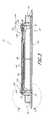
- FIG. 1is a perspective view of a lighting apparatus having features in accordance with an embodiment of the present invention.
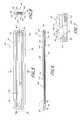
- FIG. 2is an exploded view of the lighting apparatus of FIG. 1 .
- FIG. 3is a cross-sectional view showing the apparatus of FIG. 1 taken along lines 3 - 3 .
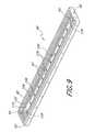
- FIG. 4is a perspective view of an embodiment of a base portion.
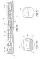
- FIG. 5is a top view of the base portion of FIG. 4 .
- FIG. 6is a cross-sectional view taken along lines 6 - 6 of FIG. 5 .
- FIG. 7is a close-up view taken along lines 7 - 7 of FIG. 6 .
- FIG. 8is a cross-sectional view taken along lines 8 - 8 of FIG. 5 .
- FIG. 9shows an embodiment of a base portion having circuit traces disposed thereon.
- FIG. 10is a top view of the base portion of FIG. 9 showing the circuit traces.
- FIG. 10Ais a close up view of a portion of FIG. 10 taken along lines 10 A- 10 A.
- FIG. 11shows an embodiment of a member.
- FIG. 12is a close-up of a portion of a lighting apparatus taken along lines 12 - 12 of FIG. 3 .
- FIG. 13shows a perspective view of a cover sheet.
- FIG. 14is an end view of the cover sheet of FIG. 13 , showing layers.
- FIG. 15Ais a perspective view of a cover frame.
- FIG. 15Bis a side view of the cover frame of FIG. 15A .
- FIG. 15Cis a top view of the cover frame of FIG. 15A .
- FIG. 16Ais a perspective view of a contact sleeve.
- FIG. 16Bis a side view of the contact sleeve of FIG. 16A .
- FIG. 16Cis a top view of the contact sleeve of FIG. 16A .
- FIG. 17shows an arrangement in which several lighting apparatuses are electrically connected to a power supply and to one another.
- FIG. 18shows a plurality of lighting apparatuses being fit into an embodiment of a housing.
- FIG. 19is a close-up view of a lighting apparatus being fit into an embodiment of a housing.
- the lighting apparatus 30preferably comprises a power module 32 and a light emitting diode (LED) module 34 that are connected to one another.
- the LED module 34comprises a heat conductive base 40 upon which a plurality of electrically conductive traces 42 are disposed.
- An array of LEDs 44is mounted on the base 40 and electrically connected to the traces 42 .
- Transmissive material 46is disposed in and around the LEDs 44 , and a cover 50 is placed thereover.
- the cover 50preferably comprises a phosphor.
- the power module 32comprises an elongate body 52 having a first end 54 and a second end 56 .
- Each of the first and second ends 54 , 56include positive and negative connectors 58 , 60 that are adapted to connect to flexible conductors such as electrical wire.
- the first and second ends 54 , 56each include a mounting flange 62 adapted to receive a fastener in order to secure the lighting apparatus 30 to a mount surface.
- other mounting structures and methodscan be employed.
- two-sided tapecan be disposed on a bottom surface 64 of the power module 32 in order to secure the apparatus to a mount surface.
- the power module 32preferably is configured to be powered by an external power supply and receives constant input voltage of about 12 or 24 volts DC.
- the power module 32converts the constant input voltage into a constant current for electrically driving the LEDs 44 of the LED module 34 .
- the currentpreferably is pulsed with a frequency in excess of about 300 Hz.
- a power module 32 exhibiting such electrical behaviorcan be obtained from Advance Transformer/Phillips.
- the illustrated power module 32has a generally flat mount surface 66 configured to engage and support the LED module 34 .
- First and second mount holes 68 , 70facilitate mounting of the LED module 34 to the power module 32 .
- Poweris supplied from the power module 32 to the LED module 34 between an input node 72 and an output node 74 .
- the input and output nodes 72 , 74are disposed at or in the first and second mount holes 68 , 70 .
- the base 40preferably has a bottom surface 80 , a top surface 82 , first and second sides 84 , 86 , and first and second ends 90 , 92 .
- Mount holes 94 , 96are disposed adjacent the first and second ends 90 , 92 , respectively, and are configured to align with the mount holes 68 , 70 in the power module 32 .
- the top surface 82preferably has a cavity 100 formed therein.
- An upper wall 102extends from the top surface 82 to a step 104 .
- a lower wall 106extends from the step 104 to a cavity surface 110 .
- the portion of the cavity 100 defined within the upper wall 102 and step 104is referred to as an upper cavity 112 ; the portion of the cavity 100 defined within the lower wall 106 between the step 104 and the cavity surface 110 is referred to as a lower cavity 114 .
- the base 40comprises a first portion 120 and a second portion 122 .
- the majority of the volume of the base 40comprises the first portion 120 , which preferably is constructed of a heat conductive material, such as a metal or metal alloy.
- the first portion 120comprises an aluminum silicon carbon (AlSiC) material. It is to be understood that, in other embodiments, the first portion can be made of other heat conductive materials, and even a combination of two or more different heat conductive materials.
- the second portion 122 of the base 40preferably comprises a relatively thin sheet of another heat conductive material.
- the sheetis referred to as a heat conductive insert.
- a coefficient of thermal conductivity of the second portion 122is greater than a coefficient of thermal conductivity of any part of the first portion 120 .
- the second portion 122is centered just below the cavity 100 and is enclosed within the base 40 . Heat from within the lower cavity 114 is drawn into the first portion 120 and flows readily to the second portion 122 .
- the second portion 122distributes heat received from the lower cavity away from the lower cavity and to other locations within the first portion 120 , specifically to the first and second sides 84 , 86 which, in the illustrated embodiment, are part of the first portion 120 . From the sides 84 , 86 , the heat is radiated away from the base 40 to the atmosphere or an adjacent heat sink.
- the second portion 122preferably comprises a relatively thin generally planar sheet comprising a material having not only high thermal conductivity, but also having directional thermal conductivity properties.
- the flat sheet of the second portion 122conducts heat in a plane generally parallel to a center plane of the flat sheet of material.
- the second portion 122comprises strands of material that preferentially conduct heat along the length of the strand.
- the strandspreferably are oriented to direct heat toward the first and second sides 84 , 86 of the second portion.
- the second portion 122comprises carbon strands and, more specifically, highly-oriented pyrolytic graphite.
- the second portionhas a very high thermal conductivity, such as greater than about 1,000 W/(m*K) or, in another embodiment, at least about 1,350-1,450 W/(m*K).
- a base member having properties as discussed above in connection with the illustrated embodimentcan be obtained from Ceramics Process Systems Corporation of Chartly, Mass.
- the second portioncomprises a relatively thin sheet that is made of a material having a high thermal conductivity but which does not necessarily preferentially conduct heat in a plane generally parallel to a center plane of the second portion.
- the second portionmay vary in size, shape and layout.
- the second portionhas a pyramid-shaped cross-section and is disposed beneath the cavity surface 110 .
- the second portion 122is disposed generally in the center of the base 40 , and is substantially enclosed within the first portion 120 . It is to be understood that, in other embodiments, the second portion can extend further from the center into the first and second sides, and can even extend out of at least one of the sides of the base. In yet further embodiments, the first portion may include fins to radiate heat to the atmosphere surrounding the first portion.
- the base 40preferably is made of a heat conductive material.
- the basecomprises AlSiC, which is also electrically conductive.
- the electrically conductive basecomprises a layer of oxide disposed thereon.
- the oxideis a native oxide of the electrically conductive material of which the base is made.
- the oxide layerpreferably has a thickness of about 2 mils or less.
- a native oxide layeris grown on the conductive base 40 via an anodization process. More particularly, the base preferably is anodized in an electrochemical bath in order to grow the native oxide thereon. It is to be understood that, in other embodiments, other methods and apparatus can be used to deposit a non-conductive layer on the base. For example, powder coating or plating with any non-electrically-conductive electroless metal can be acceptable.
- the native oxide grown through anodizationfunctions as a dielectric to electrically insulate the base 40 .
- electrically conductive circuit traces 42preferably are disposed on the cavity surface 110 of the base 40 , and are attached to the oxide layer. As such, the electrical traces 42 are electrically insulated from the base 40 by the oxide layer. The electrically conductive traces 42 are arranged to provide an electrical pathway to power a plurality of LEDs 44 attached to the traces. Contact pads 126 of the traces 42 are configured to accept LEDs mounted thereon. In the illustrated embodiment, the contact pads 126 are thicker than other portions of the traces 42 .
- the electrical circuit traces 42are configured to mount ten LEDs 44 in an electrically parallel fashion. It is to be understood that, in other embodiments, any desired number of LEDs can be used, and different electrical arrangements can be employed. For example, the LEDs can be arranged electrically in series. Also, more than one set of serially-connected LEDs can be arranged so that the sets are electrically in parallel relative to one another within the cavity 100 . Further, the LEDs can be disposed in different mechanical arrangements. For example, in the illustrated embodiment, the ten LEDs 44 are equally spaced and arranged in a serial array. It is to be understood that other spacings and arrangements can be accomplished as desired.
- the circuit traces 42comprise an electrically conductive material such as aluminum or another metal laid upon the oxide layer of the base 40 .
- the base 40is electrically insulated from the power traces 42 by the non-conductive oxide layer.
- the power traces 42are laid on the oxide layer by any suitable method, including methods currently employed by vendors such as Kyocera and IJ Research.
- the power traces 42have terminus portions 128 disposed adjacent the mount holes 94 , 96 at either end of the base 40 .
- a conductive contact member 130preferably is electrically connected at each terminus 128 and extends upwardly from the power traces 42 .
- the contact member 130extends upwardly up to or beyond the level of the step 104 between the upper and lower walls 102 , 106 in the cavity 100 .
- the contact member 130is bonded, co-formed, or otherwise attached to the respective terminus portion 128 .
- the contact member 130is soldered in place on the terminus portion 128 .
- the contact member 130comprises a cylindrical pin. It is to be understood that, in other embodiments, other shapes and sizes of contact members can be employed.
- the lower cavity 114preferably is filled with a transmissive material 46 .
- the transmissive material 46comprises a mixture of silicone and glass.
- the transmissive material 46is chosen from materials known as sol-gels.
- the transmissive material 46comprises a mixture of silicone and glass available under the trademark SogelTM, which can be obtained from WaveGuide.
- the cover 50is configured to be disposed over the cavity 100 of the base 40 so as to cover the array of LEDs 44 and receive light from the LEDs.
- the cover 50preferably comprises a multi-layer sheet 132 .
- the sheet 132comprises first and second layers 134 , 136 of glass that sandwich a layer of phosphor 138 .
- the glass and phosphor layers 134 , 136 , 138preferably are connected by a layer of adhesive 139 .
- the phosphor 138is sandwiched between two layers of glass 134 , 136 .
- the phosphoris mixed, embedded and/or suspended in the glass so that the sheet comprises only a single layer of phosphor-including glass.
- the sheetcomprises inorganic material that will not degrade when exposed to ultraviolet light.
- the LEDsare configured to emit ultraviolet light.
- the cover 50 sheetcan be colored or include one or more colored layers, and may or may not include a phosphor.
- each cover frame 140preferably includes a body 142 having a mount hole 144 formed therethrough, which mount hole 144 is configured to align with the mount holes 144 of the base 40 and power module 32 .
- a gripping portion 146 of the frame body 142comprises opposing jaws 148 that are configured to hold the sheet 132 .
- the cover 50When the cover 50 and base 40 are assembled, as shown in FIGS. 3 and 12 , the cover 50 is configured to fit at least partially within the upper wall 102 in the upper portion 112 of the base cavity 100 . Preferably, the cover 50 fits generally snugly in the upper portion 112 so that substantially no light emitted by the LEDs 44 exits the cavity 100 without first contacting the cover 50 . In another embodiment, the cover 50 generally engages the step 104 so as to substantially enclose the lower portion 114 of the cavity 100 .
- the transmissive material 46is deposited in the cavity 100 so as to surround the LEDs 44 .
- excess transmissive material 46will squeeze past the cover 50 and can be removed from the device.
- the sheet 132preferably abuts the transmissive material 46 and/or the LEDs 44 so that there is very little or substantially no air between the LEDs 44 and the cover sheet 132 .
- the transmissive material 46 , LEDs 44 , and sheet 132comprise a graduated refractive index. More specifically, in the illustrated embodiment the LEDs 44 each preferably have a refractive index of between about 2.1 to 2.8.
- the transmissive material 46preferably has a refractive index between about 1.5 to 1.8.
- a first layer of glass 134 in the sheetpreferably has a refractive index between about 1.45 to 1.5.
- a second layer of glass 136 in the sheetpreferably has a refractive index of about 1.40 to 1.45.
- the several different layers of materialscollectively comprise a graduated refractive index, and the refractive indices of the layers are relatively closely matched so as to maximize light output from the apparatus 30 .
- the cover 50comprises a phosphor 138
- light from the LEDs 44is absorbed by the phosphor, which emits light in response to such optical pumping by the LEDs.
- a contact sleeve 150preferably is disposed in each cover frame hole 144 .
- the contact sleeve 150preferably is made of a conductive material such as a metal.
- the contact sleeve 150comprises an elongate body portion 152 that is configured to fit through the cover frame hole 144 , and a flange portion 154 that extends radially outwardly from the body portion 152 .
- the contact sleeve 150is fit within the cover frame 140 and the cover 50 is placed on the base 40 so that the flange portion 154 of the contact sleeve 150 contacts and engages the corresponding contact member 130 .
- a threaded mount bolt 160extends through each contact sleeve 150 , through the base 40 , and into the corresponding mount holes 68 or 70 of the power module 32 . Threads within the power module mount holes 68 , 70 engage the respective mount bolts 160 so that the assembly is securely held together.
- the first and second mount holes 68 , 70 of the power module 32comprise first and second electrical nodes 72 , 74 . As such, when engaged in the threaded mount holes 68 , 70 , the mount bolts 160 are electrically energized.
- the mechanical connection used to complete the electrical pathwaymay be any mechanical or other connection known in the art.
- other connectionsmay include clamps, pins, screws, detents, solder, conductive adhesives, etc.
- other configurations of the power supply nodesmay appropriately be used.
- the contact sleeves and power node connectionsmay be threaded so as to enhance the mechanical and electrical connection between the mount bolts 160 , sleeve 150 and power module nodes 72 , 74 .
- each cover frame 140comprises an engagement portion shaped and configured to engage the contact member 130 when the cover 50 is secured in place on the base 40 .
- the power supply nodespreferably are configured to electrically engage the respective cover frame when the cover is in place so that an electrical pathway is established between the nodes and the contact members through the cover frames.
- one of the circuit terminus portionsis electrically connected to a respective power supply node through a trace configured to electrically engage the bolt without electrically contacting the cover.
- the other terminus portionpreferably electrically engages the cover. As such, the electrical pathway between power module nodes flows through only one end of the cover.
- multiple coversmay be provided for a single lighting apparatus 30 , each cover having different color and/or phosphor properties. As such, lighting properties of each lighting apparatus 30 can be modified by simply changing the cover 50 .
- each lighting apparatus 30is configured to be connected to other such lighting apparatus 30 by flexible conductors 164 .
- a common power supply 166is configured to supply power to the respective apparatus 30 . It is to be understood that several such lighting apparatus 30 can be joined end-to-end in a daisy-chain arrangement and used for various applications.
- the power supply modules 32are configured so that the lighting apparatus 30 are connected electrically in parallel. In another embodiment, the modules 32 may be configured so that such a daisy-chain arrangement is electrically in series.
- a housing 170preferably comprises a channel 172 that is configured to slidably accept a plurality of lighting apparatus 30 therewithin.
- a spacer 174preferably is fit between adjacent lighting apparatus 30 within the channel 172 .
- the housing 170comprises a thermally conductive material such as aluminum or another metal.
- upper and side walls 176 , 178 of the housing channel 172are configured to engage top and side surfaces 82 , 84 , 86 of the base 40 so that heat that is drawn from the LEDs 44 and directed to the sides 84 , 86 of the base 40 is further conducted from the sides 84 , 86 to the housing 170 .
- the power supply mount surface 66is heat conductive to further facilitate conduction of heat away from the base 40 .
- the side walls 178 of the housing 172preferably have a plurality of fins 180 so as to aid in convection and thus speed dissipation of heat.
- heatis drawn quickly from the LEDs 44 through the base 40 and into the housing 170 , from which it is radiated to the environment.
- the second portion 122 of the base 40facilitates such a heat pathway by quickly communicating heat generated by the LEDs 44 within the lower cavity 114 toward the sides 84 , 86 of the base 40 and to the fins 180 , which are adjacent the sides 84 , 86 .
- the convective fins 180 in the housing 170are enclosed within a cover 182 so as not to be seen from outside the housing 170 . It is to be understood that, in other embodiments, the convective fins 180 may be readily viewed from outside the housing 170 .
Landscapes
- Engineering & Computer Science (AREA)
- General Engineering & Computer Science (AREA)
- Non-Portable Lighting Devices Or Systems Thereof (AREA)
Abstract
Description
Claims (13)
Priority Applications (1)
| Application Number | Priority Date | Filing Date | Title |
|---|---|---|---|
| US11/836,057US8079731B2 (en) | 2003-09-22 | 2007-08-08 | Lighting apparatus |
Applications Claiming Priority (4)
| Application Number | Priority Date | Filing Date | Title |
|---|---|---|---|
| US50526703P | 2003-09-22 | 2003-09-22 | |
| US54627304P | 2004-02-20 | 2004-02-20 | |
| US10/945,069US7329024B2 (en) | 2003-09-22 | 2004-09-20 | Lighting apparatus |
| US11/836,057US8079731B2 (en) | 2003-09-22 | 2007-08-08 | Lighting apparatus |
Related Parent Applications (1)
| Application Number | Title | Priority Date | Filing Date |
|---|---|---|---|
| US10/945,069ContinuationUS7329024B2 (en) | 2003-09-22 | 2004-09-20 | Lighting apparatus |
Publications (2)
| Publication Number | Publication Date |
|---|---|
| US20080055915A1 US20080055915A1 (en) | 2008-03-06 |
| US8079731B2true US8079731B2 (en) | 2011-12-20 |
Family
ID=34891118
Family Applications (2)
| Application Number | Title | Priority Date | Filing Date |
|---|---|---|---|
| US10/945,069Expired - Fee RelatedUS7329024B2 (en) | 2003-09-22 | 2004-09-20 | Lighting apparatus |
| US11/836,057Expired - Fee RelatedUS8079731B2 (en) | 2003-09-22 | 2007-08-08 | Lighting apparatus |
Family Applications Before (1)
| Application Number | Title | Priority Date | Filing Date |
|---|---|---|---|
| US10/945,069Expired - Fee RelatedUS7329024B2 (en) | 2003-09-22 | 2004-09-20 | Lighting apparatus |
Country Status (1)
| Country | Link |
|---|---|
| US (2) | US7329024B2 (en) |
Cited By (23)
| Publication number | Priority date | Publication date | Assignee | Title |
|---|---|---|---|---|
| US20120002415A1 (en)* | 2010-06-30 | 2012-01-05 | Nelson Peter K | Ventilation for led lighting |
| USD662653S1 (en)* | 2011-11-29 | 2012-06-26 | Full Throttle Films, Inc. | Linear lighting track mount |
| USD663068S1 (en)* | 2011-11-29 | 2012-07-03 | Full Throttle Films, Inc. | Linear lighting track |
| USD671251S1 (en) | 2011-04-27 | 2012-11-20 | Digital Lumens, Inc. | Lighting fixture |
| USD676185S1 (en)* | 2011-04-27 | 2013-02-12 | Digital Lumens, Inc. | Lighting apparatus |
| US8610376B2 (en) | 2008-04-14 | 2013-12-17 | Digital Lumens Incorporated | LED lighting methods, apparatus, and systems including historic sensor data logging |
| US8729833B2 (en) | 2012-03-19 | 2014-05-20 | Digital Lumens Incorporated | Methods, systems, and apparatus for providing variable illumination |
| US8754589B2 (en) | 2008-04-14 | 2014-06-17 | Digtial Lumens Incorporated | Power management unit with temperature protection |
| US8805550B2 (en) | 2008-04-14 | 2014-08-12 | Digital Lumens Incorporated | Power management unit with power source arbitration |
| US8823277B2 (en) | 2008-04-14 | 2014-09-02 | Digital Lumens Incorporated | Methods, systems, and apparatus for mapping a network of lighting fixtures with light module identification |
| US8841859B2 (en) | 2008-04-14 | 2014-09-23 | Digital Lumens Incorporated | LED lighting methods, apparatus, and systems including rules-based sensor data logging |
| US8866408B2 (en) | 2008-04-14 | 2014-10-21 | Digital Lumens Incorporated | Methods, apparatus, and systems for automatic power adjustment based on energy demand information |
| US8926145B2 (en) | 2008-12-05 | 2015-01-06 | Permlight Products, Inc. | LED-based light engine having thermally insulated zones |
| US8939634B2 (en) | 2010-06-30 | 2015-01-27 | Abl Ip Holding Llc | Egress lighting for two module luminaires |
| US8954170B2 (en) | 2009-04-14 | 2015-02-10 | Digital Lumens Incorporated | Power management unit with multi-input arbitration |
| US9014829B2 (en) | 2010-11-04 | 2015-04-21 | Digital Lumens, Inc. | Method, apparatus, and system for occupancy sensing |
| US9072133B2 (en) | 2008-04-14 | 2015-06-30 | Digital Lumens, Inc. | Lighting fixtures and methods of commissioning lighting fixtures |
| US9510426B2 (en) | 2011-11-03 | 2016-11-29 | Digital Lumens, Inc. | Methods, systems, and apparatus for intelligent lighting |
| USD774686S1 (en)* | 2015-02-27 | 2016-12-20 | Star Headlight & Lantern Co., Inc. | Optical lens for projecting light from LED light emitters |
| US9924576B2 (en) | 2013-04-30 | 2018-03-20 | Digital Lumens, Inc. | Methods, apparatuses, and systems for operating light emitting diodes at low temperature |
| US10264652B2 (en) | 2013-10-10 | 2019-04-16 | Digital Lumens, Inc. | Methods, systems, and apparatus for intelligent lighting |
| US10451226B2 (en) | 2015-09-14 | 2019-10-22 | ProPhotonix Limited | Modular LED line light |
| US10485068B2 (en) | 2008-04-14 | 2019-11-19 | Digital Lumens, Inc. | Methods, apparatus, and systems for providing occupancy-based variable lighting |
Families Citing this family (166)
| Publication number | Priority date | Publication date | Assignee | Title |
|---|---|---|---|---|
| US7005679B2 (en)* | 2003-05-01 | 2006-02-28 | Cree, Inc. | Multiple component solid state white light |
| US7145125B2 (en) | 2003-06-23 | 2006-12-05 | Advanced Optical Technologies, Llc | Integrating chamber cone light using LED sources |
| US7521667B2 (en) | 2003-06-23 | 2009-04-21 | Advanced Optical Technologies, Llc | Intelligent solid state lighting |
| US7329024B2 (en) | 2003-09-22 | 2008-02-12 | Permlight Products, Inc. | Lighting apparatus |
| US7102172B2 (en)* | 2003-10-09 | 2006-09-05 | Permlight Products, Inc. | LED luminaire |
| US8188503B2 (en)* | 2004-05-10 | 2012-05-29 | Permlight Products, Inc. | Cuttable illuminated panel |
| US8125137B2 (en) | 2005-01-10 | 2012-02-28 | Cree, Inc. | Multi-chip light emitting device lamps for providing high-CRI warm white light and light fixtures including the same |
| US7564180B2 (en) | 2005-01-10 | 2009-07-21 | Cree, Inc. | Light emission device and method utilizing multiple emitters and multiple phosphors |
| US7758223B2 (en) | 2005-04-08 | 2010-07-20 | Toshiba Lighting & Technology Corporation | Lamp having outer shell to radiate heat of light source |
| JP4241658B2 (en)* | 2005-04-14 | 2009-03-18 | シチズン電子株式会社 | Light emitting diode light source unit and light emitting diode light source formed using the same |
| US7918591B2 (en)* | 2005-05-13 | 2011-04-05 | Permlight Products, Inc. | LED-based luminaire |
| US7872430B2 (en) | 2005-11-18 | 2011-01-18 | Cree, Inc. | Solid state lighting panels with variable voltage boost current sources |
| EP1963740A4 (en) | 2005-12-21 | 2009-04-29 | Cree Led Lighting Solutions | Lighting device and lighting method |
| WO2007075742A2 (en)* | 2005-12-21 | 2007-07-05 | Cree Led Lighting Solutions, Inc. | Lighting device |
| CN101351891B (en) | 2005-12-22 | 2014-11-19 | 科锐公司 | lighting device |
| US7852009B2 (en)* | 2006-01-25 | 2010-12-14 | Cree, Inc. | Lighting device circuit with series-connected solid state light emitters and current regulator |
| US9179513B2 (en) | 2006-02-09 | 2015-11-03 | Xinxin Shan | LED lighting system |
| US8791650B2 (en) | 2006-02-09 | 2014-07-29 | Led Smart Inc. | LED lighting system |
| US7307391B2 (en)* | 2006-02-09 | 2007-12-11 | Led Smart Inc. | LED lighting system |
| US10285225B2 (en) | 2006-02-09 | 2019-05-07 | Led Smart Inc. | LED lighting system |
| US8115411B2 (en)* | 2006-02-09 | 2012-02-14 | Led Smart, Inc. | LED lighting system |
| US9516706B2 (en) | 2006-02-09 | 2016-12-06 | Led Smart Inc. | LED lighting system |
| US10887956B2 (en) | 2006-02-09 | 2021-01-05 | Led Smart Inc. | LED lighting system |
| US7828460B2 (en) | 2006-04-18 | 2010-11-09 | Cree, Inc. | Lighting device and lighting method |
| US8513875B2 (en) | 2006-04-18 | 2013-08-20 | Cree, Inc. | Lighting device and lighting method |
| US9084328B2 (en) | 2006-12-01 | 2015-07-14 | Cree, Inc. | Lighting device and lighting method |
| WO2007124036A2 (en) | 2006-04-20 | 2007-11-01 | Cree Led Lighting Solutions, Inc. | Lighting device and lighting method |
| US7625103B2 (en)* | 2006-04-21 | 2009-12-01 | Cree, Inc. | Multiple thermal path packaging for solid state light emitting apparatus and associated assembling methods |
| US7648257B2 (en) | 2006-04-21 | 2010-01-19 | Cree, Inc. | Light emitting diode packages |
| EP2021688B1 (en)* | 2006-05-05 | 2016-04-27 | Cree, Inc. | Lighting device |
| WO2007142946A2 (en) | 2006-05-31 | 2007-12-13 | Cree Led Lighting Solutions, Inc. | Lighting device and method of lighting |
| US7794114B2 (en)* | 2006-10-11 | 2010-09-14 | Cree, Inc. | Methods and apparatus for improved heat spreading in solid state lighting systems |
| US8029155B2 (en) | 2006-11-07 | 2011-10-04 | Cree, Inc. | Lighting device and lighting method |
| KR101408613B1 (en)* | 2006-11-30 | 2014-06-20 | 크리, 인코포레이티드 | Self-ballasted solid state lighting devices |
| US9441793B2 (en) | 2006-12-01 | 2016-09-13 | Cree, Inc. | High efficiency lighting device including one or more solid state light emitters, and method of lighting |
| US7918581B2 (en) | 2006-12-07 | 2011-04-05 | Cree, Inc. | Lighting device and lighting method |
| KR101184455B1 (en)* | 2006-12-22 | 2012-09-20 | 삼성전자주식회사 | A vessel holder and A dish washing machine including thereof |
| US7815341B2 (en)* | 2007-02-14 | 2010-10-19 | Permlight Products, Inc. | Strip illumination device |
| TWI560405B (en) | 2007-02-22 | 2016-12-01 | Cree Inc | Lighting devices, methods of lighting, light filters and methods of filtering light |
| US8207678B1 (en)* | 2007-03-09 | 2012-06-26 | Barco, Inc. | LED lighting fixture |
| US8703492B2 (en)* | 2007-04-06 | 2014-04-22 | Qiagen Gaithersburg, Inc. | Open platform hybrid manual-automated sample processing system |
| JP2010527510A (en) | 2007-05-08 | 2010-08-12 | クリー エル イー ディー ライティング ソリューションズ インコーポレイテッド | Lighting device and lighting method |
| US7744243B2 (en) | 2007-05-08 | 2010-06-29 | Cree Led Lighting Solutions, Inc. | Lighting device and lighting method |
| EP2156090B1 (en) | 2007-05-08 | 2016-07-06 | Cree, Inc. | Lighting device and lighting method |
| US10030824B2 (en) | 2007-05-08 | 2018-07-24 | Cree, Inc. | Lighting device and lighting method |
| US7863635B2 (en)* | 2007-08-07 | 2011-01-04 | Cree, Inc. | Semiconductor light emitting devices with applied wavelength conversion materials |
| US20090039375A1 (en)* | 2007-08-07 | 2009-02-12 | Cree, Inc. | Semiconductor light emitting devices with separated wavelength conversion materials and methods of forming the same |
| CN101868815B (en)* | 2007-09-17 | 2014-08-20 | 照明有限责任公司 | LED lighting system for a cabinet sign |
| JP2011501417A (en) | 2007-10-10 | 2011-01-06 | クリー エル イー ディー ライティング ソリューションズ インコーポレイテッド | Lighting device and manufacturing method |
| CA2640913C (en)* | 2007-10-12 | 2017-05-09 | The L.D. Kichler Co. | Positionable lighting systems and methods |
| JP4569683B2 (en) | 2007-10-16 | 2010-10-27 | 東芝ライテック株式会社 | Light emitting element lamp and lighting apparatus |
| USD602196S1 (en)* | 2007-10-25 | 2009-10-13 | Feelux Co., Ltd. | Socket for fluorescent lamp |
| US10655837B1 (en) | 2007-11-13 | 2020-05-19 | Silescent Lighting Corporation | Light fixture assembly having a heat conductive cover with sufficiently large surface area for improved heat dissipation |
| US8789980B1 (en) | 2007-11-13 | 2014-07-29 | Silescent Lighting Corporation | Light fixture assembly |
| US8360614B1 (en)* | 2007-11-13 | 2013-01-29 | Inteltech Corporation | Light fixture assembly having improved heat dissipation capabilities |
| US7810960B1 (en)* | 2007-11-13 | 2010-10-12 | Inteltech Corporation | Light fixture assembly having improved heat dissipation capabilities |
| US8534873B1 (en) | 2007-11-13 | 2013-09-17 | Inteltech Corporation | Light fixture assembly |
| US9080760B1 (en) | 2007-11-13 | 2015-07-14 | Daryl Soderman | Light fixture assembly |
| US8118447B2 (en) | 2007-12-20 | 2012-02-21 | Altair Engineering, Inc. | LED lighting apparatus with swivel connection |
| JP5353216B2 (en)* | 2008-01-07 | 2013-11-27 | 東芝ライテック株式会社 | LED bulb and lighting fixture |
| US7726840B2 (en)* | 2008-03-04 | 2010-06-01 | Tempo Industries, Inc. | Modular LED lighting fixtures |
| US20090244884A1 (en)* | 2008-03-31 | 2009-10-01 | True Manufacturing Co. Inc. | Glass door merchandiser having led lights and mounting assembly therefor |
| USD584180S1 (en)* | 2008-04-10 | 2009-01-06 | Whelen Engineering Company, Inc. | Lens and frame for warning lights |
| KR100874609B1 (en)* | 2008-04-22 | 2008-12-17 | 이위재 | LED fluorescent lamp type |
| US8360599B2 (en) | 2008-05-23 | 2013-01-29 | Ilumisys, Inc. | Electric shock resistant L.E.D. based light |
| USD600584S1 (en)* | 2008-06-23 | 2009-09-22 | Whelen Engineering Company, Inc | Warning light assembly and flange |
| US20090316405A1 (en)* | 2008-06-23 | 2009-12-24 | Chen-Hui Lai | Configurable LED lighting device |
| US8240875B2 (en) | 2008-06-25 | 2012-08-14 | Cree, Inc. | Solid state linear array modules for general illumination |
| CN103470983A (en)* | 2008-06-27 | 2013-12-25 | 东芝照明技术株式会社 | Light-emitting element lamp and lighting equipment |
| US20100046221A1 (en)* | 2008-08-19 | 2010-02-25 | Jason Loomis Posselt | LED Source Adapted for Light Bulbs and the Like |
| US8653984B2 (en) | 2008-10-24 | 2014-02-18 | Ilumisys, Inc. | Integration of LED lighting control with emergency notification systems |
| US8901823B2 (en) | 2008-10-24 | 2014-12-02 | Ilumisys, Inc. | Light and light sensor |
| US7938562B2 (en) | 2008-10-24 | 2011-05-10 | Altair Engineering, Inc. | Lighting including integral communication apparatus |
| US8214084B2 (en) | 2008-10-24 | 2012-07-03 | Ilumisys, Inc. | Integration of LED lighting with building controls |
| US8324817B2 (en) | 2008-10-24 | 2012-12-04 | Ilumisys, Inc. | Light and light sensor |
| US7740380B2 (en)* | 2008-10-29 | 2010-06-22 | Thrailkill John E | Solid state lighting apparatus utilizing axial thermal dissipation |
| WO2011109006A1 (en)* | 2010-03-04 | 2011-09-09 | Thrailkill John E | Thermal dissipator utilizing laminar thermal transfer member |
| US8651711B2 (en) | 2009-02-02 | 2014-02-18 | Apex Technologies, Inc. | Modular lighting system and method employing loosely constrained magnetic structures |
| US8231245B2 (en)* | 2009-02-13 | 2012-07-31 | Dialight Corporation | LED lighting fixture |
| JP5333758B2 (en) | 2009-02-27 | 2013-11-06 | 東芝ライテック株式会社 | Lighting device and lighting fixture |
| US8921876B2 (en)* | 2009-06-02 | 2014-12-30 | Cree, Inc. | Lighting devices with discrete lumiphor-bearing regions within or on a surface of remote elements |
| JP5348410B2 (en)* | 2009-06-30 | 2013-11-20 | 東芝ライテック株式会社 | Lamp with lamp and lighting equipment |
| JP5354191B2 (en)* | 2009-06-30 | 2013-11-27 | 東芝ライテック株式会社 | Light bulb shaped lamp and lighting equipment |
| JP2011049527A (en)* | 2009-07-29 | 2011-03-10 | Toshiba Lighting & Technology Corp | Led lighting equipment |
| US8860314B2 (en) | 2009-09-03 | 2014-10-14 | Koninklijke Philips N.V. | LED lamp |
| JP2011071242A (en)* | 2009-09-24 | 2011-04-07 | Toshiba Lighting & Technology Corp | Light emitting device and illuminating device |
| CN102630288B (en) | 2009-09-25 | 2015-09-09 | 科锐公司 | Lighting fixtures with low glare and high brightness level uniformity |
| JP2011091033A (en)* | 2009-09-25 | 2011-05-06 | Toshiba Lighting & Technology Corp | Light-emitting module, bulb-shaped lamp and lighting equipment |
| US8678618B2 (en) | 2009-09-25 | 2014-03-25 | Toshiba Lighting & Technology Corporation | Self-ballasted lamp having a light-transmissive member in contact with light emitting elements and lighting equipment incorporating the same |
| CN102032481B (en)* | 2009-09-25 | 2014-01-08 | 东芝照明技术株式会社 | Lighting lamps and lighting fixtures with sockets |
| US8324789B2 (en)* | 2009-09-25 | 2012-12-04 | Toshiba Lighting & Technology Corporation | Self-ballasted lamp and lighting equipment |
| BR112012010040A2 (en)* | 2009-10-27 | 2020-08-18 | GE Lighting Solutions, LLC | refractive optics to provide uniform lighting in a showcase |
| USD627672S1 (en) | 2009-12-18 | 2010-11-23 | David D Shin | Warning light lens |
| USD614062S1 (en) | 2009-12-18 | 2010-04-20 | David D Shin | Warning light lens |
| USD618572S1 (en) | 2009-12-18 | 2010-06-29 | David D Shin | Warning light lens |
| USD614522S1 (en) | 2009-12-18 | 2010-04-27 | David D Shin | Warning light lens |
| USD614063S1 (en) | 2009-12-18 | 2010-04-20 | David D Shin | Warning light lens |
| DE102010002228A1 (en)* | 2010-02-23 | 2011-08-25 | Osram Gesellschaft mit beschränkter Haftung, 81543 | lighting device |
| JP5257622B2 (en)* | 2010-02-26 | 2013-08-07 | 東芝ライテック株式会社 | Light bulb shaped lamp and lighting equipment |
| US9275979B2 (en) | 2010-03-03 | 2016-03-01 | Cree, Inc. | Enhanced color rendering index emitter through phosphor separation |
| CN102200226A (en)* | 2010-03-23 | 2011-09-28 | 欧司朗有限公司 | Self-ballasting light emitting diode (LED) lamp tube and lamp with same |
| CA2792940A1 (en) | 2010-03-26 | 2011-09-19 | Ilumisys, Inc. | Led light with thermoelectric generator |
| US8540401B2 (en) | 2010-03-26 | 2013-09-24 | Ilumisys, Inc. | LED bulb with internal heat dissipating structures |
| US8668361B2 (en) | 2010-09-22 | 2014-03-11 | Bridgelux, Inc. | LED-based replacement for fluorescent light source |
| EP2633227B1 (en) | 2010-10-29 | 2018-08-29 | iLumisys, Inc. | Mechanisms for reducing risk of shock during installation of light tube |
| KR20120067543A (en)* | 2010-12-16 | 2012-06-26 | 삼성엘이디 주식회사 | Light emitting module and backlight unit using the same |
| US11251164B2 (en) | 2011-02-16 | 2022-02-15 | Creeled, Inc. | Multi-layer conversion material for down conversion in solid state lighting |
| US9506628B1 (en)* | 2011-05-28 | 2016-11-29 | Deepsea Power & Lighting, Inc. | Semiconductor lighting devices and methods |
| US8545045B2 (en)* | 2011-07-12 | 2013-10-01 | Rev-A-Shelf Company, Llc | Modular LED lighting systems and kits |
| US9055630B1 (en) | 2011-07-21 | 2015-06-09 | Dale B. Stepps | Power control system and method for providing an optimal power level to a designated light assembly |
| US8643300B1 (en) | 2011-07-21 | 2014-02-04 | Dale B. Stepps | Power control system and method for providing an optimal power level to a designated light fixture |
| US9109775B2 (en)* | 2011-12-16 | 2015-08-18 | Fortress Iron, Lp | Accent lighting system for decks, patios and indoor/outdoor spaces |
| KR20130080259A (en)* | 2012-01-04 | 2013-07-12 | 삼성전자주식회사 | Light emitting device |
| USD692597S1 (en) | 2012-01-18 | 2013-10-29 | Ilumisys, Inc. | LED light tube |
| EP2820351B1 (en)* | 2012-03-01 | 2017-02-01 | Philips Lighting Holding B.V. | Led lighting arrangement |
| US9184518B2 (en) | 2012-03-02 | 2015-11-10 | Ilumisys, Inc. | Electrical connector header for an LED-based light |
| DE102012205806B4 (en)* | 2012-04-10 | 2017-02-02 | Osram Gmbh | Mounting arrangement for mounting a housing of an LED module |
| US9163794B2 (en) | 2012-07-06 | 2015-10-20 | Ilumisys, Inc. | Power supply assembly for LED-based light tube |
| US9271367B2 (en) | 2012-07-09 | 2016-02-23 | Ilumisys, Inc. | System and method for controlling operation of an LED-based light |
| USD681866S1 (en)* | 2012-07-23 | 2013-05-07 | Foxsemicon Integrated Technology, Inc. | LED lamp cover |
| US9416925B2 (en) | 2012-11-16 | 2016-08-16 | Permlight Products, Inc. | Light emitting apparatus |
| DE102012222814B4 (en)* | 2012-12-11 | 2016-05-04 | Sgl Carbon Se | Lighting system for surface components such as ceilings or walls |
| TWI548834B (en) | 2012-12-12 | 2016-09-11 | 財團法人工業技術研究院 | Assembly structure and lighting device having the same |
| DE102013103673A1 (en)* | 2012-12-14 | 2014-06-18 | Weidmüller Interface GmbH & Co. KG | Lighting device and lighting arrangement for illuminating the interior of a tower or tunnel |
| EP2921764B1 (en)* | 2012-12-20 | 2017-10-11 | CCS Inc. | Line light irradiation device |
| US9313849B2 (en) | 2013-01-23 | 2016-04-12 | Silescent Lighting Corporation | Dimming control system for solid state illumination source |
| US20140241006A1 (en)* | 2013-02-28 | 2014-08-28 | Dakkota Lighting Technologies Llc | Light plate assembly |
| EP2778518B1 (en) | 2013-03-11 | 2016-04-20 | OSRAM GmbH | Lighting device |
| US9285084B2 (en) | 2013-03-14 | 2016-03-15 | Ilumisys, Inc. | Diffusers for LED-based lights |
| US9192001B2 (en) | 2013-03-15 | 2015-11-17 | Ambionce Systems Llc. | Reactive power balancing current limited power supply for driving floating DC loads |
| KR20140124509A (en)* | 2013-04-17 | 2014-10-27 | 주식회사 포스코엘이디 | Rectangle led luminaire |
| US9028105B2 (en) | 2013-05-02 | 2015-05-12 | Lunera Lighting, Inc. | Retrofit LED lighting system for replacement of fluorescent lamp |
| US9243757B2 (en) | 2013-05-02 | 2016-01-26 | Lunera Lighting, Inc. | Retrofit LED lighting system for replacement of fluorescent lamp |
| CN104241262B (en) | 2013-06-14 | 2020-11-06 | 惠州科锐半导体照明有限公司 | Light emitting device and display device |
| USD770317S1 (en)* | 2013-07-19 | 2016-11-01 | Weidmueller Interface Gmbh & Co. Kg | LED lights |
| US9267650B2 (en) | 2013-10-09 | 2016-02-23 | Ilumisys, Inc. | Lens for an LED-based light |
| CN106063381A (en) | 2014-01-22 | 2016-10-26 | 伊卢米斯公司 | LED-based light with addressed LEDs |
| EP2942561B1 (en)* | 2014-04-15 | 2017-07-19 | OSRAM GmbH | A lens for lighting devices, corresponding lighting device and method |
| US9410688B1 (en) | 2014-05-09 | 2016-08-09 | Mark Sutherland | Heat dissipating assembly |
| US9510400B2 (en) | 2014-05-13 | 2016-11-29 | Ilumisys, Inc. | User input systems for an LED-based light |
| US9380653B1 (en) | 2014-10-31 | 2016-06-28 | Dale Stepps | Driver assembly for solid state lighting |
| US10161568B2 (en) | 2015-06-01 | 2018-12-25 | Ilumisys, Inc. | LED-based light with canted outer walls |
| USD780348S1 (en) | 2015-06-01 | 2017-02-28 | Ilumisys, Inc. | LED-based light tube |
| USD815763S1 (en) | 2015-07-07 | 2018-04-17 | Ilumisys, Inc. | LED-based light tube |
| USD781469S1 (en) | 2015-07-07 | 2017-03-14 | Ilumisys, Inc. | LED light tube |
| AU201612646S (en)* | 2015-11-25 | 2016-06-06 | Tridonic Gmbh & Co Kg | Housing for luminaire |
| FR3055949B1 (en)* | 2016-09-15 | 2019-11-29 | Valeo Vision | THERMAL CONNECTION FOR LUMINOUS MODULE |
| US10514138B2 (en)* | 2016-10-13 | 2019-12-24 | American Woodmark Corporation | Lighting placements system |
| DE102017100165A1 (en) | 2017-01-05 | 2018-07-05 | Jabil Optics Germany GmbH | Light-emitting device and light-emitting system |
| WO2018166292A1 (en)* | 2017-03-17 | 2018-09-20 | 欧普照明股份有限公司 | Illumination device |
| US10871275B2 (en)* | 2018-05-08 | 2020-12-22 | Nicor, Inc. | Lighting system family with modular parts and standardized extruded elements |
| FR3082281B1 (en)* | 2018-06-12 | 2020-07-10 | Stmicroelectronics (Grenoble 2) Sas | PROTECTIVE MECHANISM FOR LIGHT SOURCE |
| FR3085465B1 (en) | 2018-08-31 | 2021-05-21 | St Microelectronics Grenoble 2 | LIGHT SOURCE PROTECTION MECHANISM |
| US10865962B2 (en) | 2018-06-12 | 2020-12-15 | Stmicroelectronics (Grenoble 2) Sas | Protection mechanism for light source |
| CN210118715U (en) | 2018-06-12 | 2020-02-28 | 意法半导体(格勒诺布尔2)公司 | Housing for light source mounted on substrate and electronic apparatus |
| CN210153731U (en) | 2018-06-12 | 2020-03-17 | 意法半导体(格勒诺布尔2)公司 | Housing of light source mounted on substrate and electronic device |
| US10738985B2 (en) | 2018-06-12 | 2020-08-11 | Stmicroelectronics (Research & Development) Limited | Housing for light source |
| FR3082280B1 (en)* | 2018-06-12 | 2021-05-14 | St Microelectronics Grenoble 2 | LIGHT SOURCE PROTECTION MECHANISM |
| FR3082282B1 (en)* | 2018-06-12 | 2021-04-23 | St Microelectronics Grenoble 2 | LIGHT SOURCE PROTECTION MECHANISM |
| NL2022300B1 (en)* | 2018-12-24 | 2020-07-23 | Schreder Sa | Luminaire system with improved fastening means |
| CN111780069B (en)* | 2019-04-02 | 2022-12-13 | 台达电子工业股份有限公司 | LED driver |
| USD950826S1 (en)* | 2019-05-02 | 2022-05-03 | Signify Holding B.V. | Lighting fixture |
| USD943135S1 (en)* | 2019-10-29 | 2022-02-08 | Signify Holding B.V. | Lighting fixture |
| USD956295S1 (en)* | 2020-06-26 | 2022-06-28 | Dangxun Liu | Grill LED light |
| USD984702S1 (en)* | 2021-08-31 | 2023-04-25 | Shenzhen Chilong Industrial Co., Ltd. | Fill light |
| CN220911259U (en)* | 2023-08-29 | 2024-05-07 | 漳州立达信光电子科技有限公司 | Industrial and mining lamp capable of conveniently replacing lens |
Citations (106)
| Publication number | Priority date | Publication date | Assignee | Title |
|---|---|---|---|---|
| US4729076A (en) | 1984-11-15 | 1988-03-01 | Tsuzawa Masami | Signal light unit having heat dissipating function |
| US4855882A (en) | 1988-03-29 | 1989-08-08 | Lightgraphix Limited | Lighting apparatus |
| EP0331224A2 (en) | 1988-02-18 | 1989-09-06 | Chainlight International S.A. | Lighting string, parts for said lighting string and display device provided with said lighting string, as well as methods for producing mounting blocks and therewith a lighting string |
| US5103382A (en) | 1990-08-07 | 1992-04-07 | Stanley Electric Company | Auxiliary stop lamps |
| US5278432A (en) | 1992-08-27 | 1994-01-11 | Quantam Devices, Inc. | Apparatus for providing radiant energy |
| US5296310A (en) | 1992-02-14 | 1994-03-22 | Materials Science Corporation | High conductivity hydrid material for thermal management |
| US5410112A (en) | 1994-02-08 | 1995-04-25 | Minnesota Mining And Manufacturing Company | Safety interlock for overhead projector |
| US5430627A (en) | 1993-06-16 | 1995-07-04 | Tivoli Lighting, Inc. | Step lighting apparatus |
| US5499170A (en) | 1994-10-18 | 1996-03-12 | Gagne; Bertrand | Lighting system |
| US5607227A (en) | 1993-08-27 | 1997-03-04 | Sanyo Electric Co., Ltd. | Linear light source |
| US5635814A (en) | 1995-02-16 | 1997-06-03 | International Components Corporation | Modular battery system having a pluggable charging module |
| US5697175A (en) | 1993-10-12 | 1997-12-16 | Spectralight, Inc. | Low power drain illuminated sign |
| US5746497A (en) | 1995-06-09 | 1998-05-05 | Koito Manufacturing Co., Ltd. | Automotive signal lamps |
| US5785411A (en) | 1996-10-29 | 1998-07-28 | Tivoli Industries, Inc. | Track lighting system |
| DE29803105U1 (en) | 1998-02-21 | 1998-07-30 | Austria Haustechnik Ag, Rottenmann | Infrared-free and ultraviolet-free lighting of unpackaged baked goods |
| US5857767A (en) | 1996-09-23 | 1999-01-12 | Relume Corporation | Thermal management system for L.E.D. arrays |
| US5863467A (en) | 1996-05-03 | 1999-01-26 | Advanced Ceramics Corporation | High thermal conductivity composite and method |
| EP0921568A2 (en) | 1997-11-25 | 1999-06-09 | Matsushita Electric Works, Ltd. | LED Luminaire |
| US5953469A (en) | 1996-10-29 | 1999-09-14 | Xeotron Corporation | Optical device utilizing optical waveguides and mechanical light-switches |
| US5958572A (en) | 1997-09-30 | 1999-09-28 | Motorola, Inc. | Hybrid substrate for cooling an electronic component |
| US6017241A (en) | 1998-01-26 | 2000-01-25 | Tivoli Industries, Inc. | Aisle lighting lampholder |
| US6045240A (en) | 1996-06-27 | 2000-04-04 | Relume Corporation | LED lamp assembly with means to conduct heat away from the LEDS |
| US6056420A (en) | 1998-08-13 | 2000-05-02 | Oxygen Enterprises, Ltd. | Illuminator |
| US6075701A (en) | 1999-05-14 | 2000-06-13 | Hughes Electronics Corporation | Electronic structure having an embedded pyrolytic graphite heat sink material |
| US6131651A (en) | 1998-09-16 | 2000-10-17 | Advanced Ceramics Corporation | Flexible heat transfer device and method |
| US6249267B1 (en) | 1996-02-19 | 2001-06-19 | Rohm Co., Ltd | Display apparatus having heat dissipation |
| US6250774B1 (en) | 1997-01-23 | 2001-06-26 | U.S. Philips Corp. | Luminaire |
| US6283612B1 (en) | 2000-03-13 | 2001-09-04 | Mark A. Hunter | Light emitting diode light strip |
| US20010051450A1 (en)* | 2000-06-05 | 2001-12-13 | Ross Stanton W. | Multiple function high current interconnect with integrated bus bar |
| US6335548B1 (en) | 1999-03-15 | 2002-01-01 | Gentex Corporation | Semiconductor radiation emitter package |
| US6350039B1 (en) | 2000-10-06 | 2002-02-26 | Lee Chien-Yu | Wall switch and lamp assembly |
| US6356448B1 (en) | 1999-11-02 | 2002-03-12 | Inceptechnologies, Inc. | Inter-circuit encapsulated packaging for power delivery |
| US6367949B1 (en) | 1999-08-04 | 2002-04-09 | 911 Emergency Products, Inc. | Par 36 LED utility lamp |
| US6394626B1 (en) | 2000-04-11 | 2002-05-28 | Lumileds Lighting, U.S., Llc | Flexible light track for signage |
| US6396466B1 (en) | 1998-12-03 | 2002-05-28 | Agilent Technologies | Optical vehicle display |
| US6428189B1 (en) | 2000-03-31 | 2002-08-06 | Relume Corporation | L.E.D. thermal management |
| US20020114155A1 (en) | 2000-11-24 | 2002-08-22 | Masayuki Katogi | Illumination system and illumination unit |
| US6455930B1 (en) | 1999-12-13 | 2002-09-24 | Lamina Ceramics, Inc. | Integrated heat sinking packages using low temperature co-fired ceramic metal circuit board technology |
| US6460598B1 (en) | 2000-11-27 | 2002-10-08 | Ceramic Process Systems Corporation | Heat exchanger cast in metal matrix composite and method of making the same |
| US6480389B1 (en)* | 2002-01-04 | 2002-11-12 | Opto Tech Corporation | Heat dissipation structure for solid-state light emitting device package |
| US6483254B2 (en)* | 2000-12-20 | 2002-11-19 | Honeywell International Inc. | Led strobe light |
| US6481874B2 (en) | 2001-03-29 | 2002-11-19 | Gelcore Llc | Heat dissipation system for high power LED lighting system |
| US6485160B1 (en) | 2001-06-25 | 2002-11-26 | Gelcore Llc | Led flashlight with lens |
| USD468035S1 (en) | 2001-03-14 | 2002-12-31 | Color Kinetics, Inc. | Lighting fixture |
| US6502968B1 (en) | 1998-12-22 | 2003-01-07 | Mannesmann Vdo Ag | Printed circuit board having a light source |
| US6503626B1 (en) | 2000-02-25 | 2003-01-07 | Graftech Inc. | Graphite-based heat sink |
| US6505956B1 (en) | 2000-12-22 | 2003-01-14 | Lektron Industrial Supply, Inc. | Reeled L.E.D. assembly |
| US6509840B2 (en) | 2001-01-10 | 2003-01-21 | Gelcore Llc | Sun phantom led traffic signal |
| US6514616B1 (en) | 1998-07-08 | 2003-02-04 | Queen Mary And Westfield College, University Of London | Thermal management device and method of making such a device |
| US6517218B2 (en) | 2000-03-31 | 2003-02-11 | Relume Corporation | LED integrated heat sink |
| US6518502B2 (en) | 2001-05-10 | 2003-02-11 | Lamina Ceramics, In | Ceramic multilayer circuit boards mounted on a patterned metal support substrate |
| US6528954B1 (en) | 1997-08-26 | 2003-03-04 | Color Kinetics Incorporated | Smart light bulb |
| US6536913B1 (en)* | 1999-05-24 | 2003-03-25 | Sony Corporation | Flat display apparatus |
| US20030063463A1 (en) | 2001-10-01 | 2003-04-03 | Sloanled, Inc. | Channel letter lighting using light emitting diodes |
| US6548967B1 (en) | 1997-08-26 | 2003-04-15 | Color Kinetics, Inc. | Universal lighting network methods and systems |
| US20030072117A1 (en)* | 2001-10-12 | 2003-04-17 | Mitsubishi Denki Kabushiki Kaisha | Electric power conversion apparatus |
| US6566824B2 (en) | 2001-10-16 | 2003-05-20 | Teledyne Lighting And Display Products, Inc. | Flexible lighting segment |
| US6573536B1 (en) | 2002-05-29 | 2003-06-03 | Optolum, Inc. | Light emitting diode light source |
| US6578986B2 (en) | 2001-06-29 | 2003-06-17 | Permlight Products, Inc. | Modular mounting arrangement and method for light emitting diodes |
| US20030112627A1 (en) | 2000-09-28 | 2003-06-19 | Deese Raymond E. | Flexible sign illumination apparatus, system and method |
| US6582100B1 (en) | 2000-08-09 | 2003-06-24 | Relume Corporation | LED mounting system |
| US6616299B2 (en) | 2001-02-02 | 2003-09-09 | Gelcore Llc | Single optical element LED signal |
| US20030174517A1 (en) | 2002-03-18 | 2003-09-18 | Chris Kiraly | Extensible linear light emitting diode illumination source |
| US20030184988A1 (en) | 2002-04-01 | 2003-10-02 | Boyd Kenneth S. | Fuse relay box apparatus, methods and articles of manufacture |
| US20030189830A1 (en)* | 2001-04-12 | 2003-10-09 | Masaru Sugimoto | Light source device using led, and method of producing same |
| US6642666B1 (en) | 2000-10-20 | 2003-11-04 | Gelcore Company | Method and device to emulate a railway searchlight signal with light emitting diodes |
| US20030218417A1 (en) | 2002-05-22 | 2003-11-27 | Unity Opto Technology Co., Ltd. | Light emitting diode lamp with light emitting diode module having improved heat dissipation |
| US20030223235A1 (en) | 2002-06-03 | 2003-12-04 | Ferenc Mohacsi | LED accent lighting units |
| US6659623B2 (en)* | 2000-05-05 | 2003-12-09 | Thales Optronics (Taunton) Ltd. | Illumination system |
| JP2004002008A (en) | 2002-03-29 | 2004-01-08 | Toshiba Elevator Co Ltd | Operation button device of elevator |
| US20040041757A1 (en) | 2002-09-04 | 2004-03-04 | Ming-Hsiang Yang | Light emitting diode display module with high heat-dispersion and the substrate thereof |
| US20040042212A1 (en) | 2002-08-30 | 2004-03-04 | Gelcore, Llc | Led planar light source and low-profile headlight constructed therewith |
| WO2004021461A2 (en) | 2002-08-30 | 2004-03-11 | Gelcore Llc | Phosphor-coated led with improved efficiency |
| US6712486B1 (en) | 1999-10-19 | 2004-03-30 | Permlight Products, Inc. | Mounting arrangement for light emitting diodes |
| US20040066142A1 (en) | 2002-10-03 | 2004-04-08 | Gelcore, Llc | LED-based modular lamp |
| US6720859B2 (en) | 2002-01-10 | 2004-04-13 | Lamina Ceramics, Inc. | Temperature compensating device with embedded columnar thermistors |
| US6758573B1 (en) | 2000-06-27 | 2004-07-06 | General Electric Company | Undercabinet lighting with light emitting diode source |
| US6765237B1 (en) | 2003-01-15 | 2004-07-20 | Gelcore, Llc | White light emitting device based on UV LED and phosphor blend |
| US20040150954A1 (en) | 2003-01-31 | 2004-08-05 | Belady Christian L. | Power module for multi-chip printed circuit boards |
| US6796698B2 (en) | 2002-04-01 | 2004-09-28 | Gelcore, Llc | Light emitting diode-based signal light |
| US20040190305A1 (en) | 2003-03-31 | 2004-09-30 | General Electric Company | LED light with active cooling |
| US6799864B2 (en) | 2001-05-26 | 2004-10-05 | Gelcore Llc | High power LED power pack for spot module illumination |
| EP1479286A1 (en) | 2003-05-23 | 2004-11-24 | Gelcore LLC | Method and apparatus for irradiation of plants using light emitting diodes |
| US20040233671A1 (en)* | 2001-09-13 | 2004-11-25 | Gerhard Staufert | Led-luminous panel and carrier plate |
| WO2005004202A2 (en) | 2003-06-24 | 2005-01-13 | Gelcore Llc | Full spectrum phosphor blends for white light generation with led chips |
| US6871983B2 (en) | 2001-10-25 | 2005-03-29 | Tir Systems Ltd. | Solid state continuous sealed clean room light fixture |
| US20050077525A1 (en) | 2003-10-09 | 2005-04-14 | Manuel Lynch | LED luminaire |
| US20050128751A1 (en) | 2003-05-05 | 2005-06-16 | Color Kinetics, Incorporated | Lighting methods and systems |
| US6936857B2 (en)* | 2003-02-18 | 2005-08-30 | Gelcore, Llc | White light LED device |
| US20050243552A1 (en) | 2004-04-30 | 2005-11-03 | Lighting Science Group Corporation | Light bulb having surfaces for reflecting light produced by electronic light generating sources |
| US6966677B2 (en) | 2001-12-10 | 2005-11-22 | Galli Robert D | LED lighting assembly with improved heat management |
| US20060006405A1 (en) | 2003-05-05 | 2006-01-12 | Lamina Ceramics, Inc. | Surface mountable light emitting diode assemblies packaged for high temperature operation |
| US7081645B2 (en) | 2004-10-08 | 2006-07-25 | Bright Led Electronics Corp. | SMD(surface mount device)-type light emitting diode with high heat dissipation efficiency and high power |
| US20060221609A1 (en) | 2003-06-12 | 2006-10-05 | Ryan Patrick H Jr | Lighting strip |
| US7165863B1 (en) | 2004-09-23 | 2007-01-23 | Pricilla G. Thomas | Illumination system |
| US20070041220A1 (en) | 2005-05-13 | 2007-02-22 | Manuel Lynch | LED-based luminaire |
| US7187010B2 (en) | 2003-03-27 | 2007-03-06 | Sanken Electric Co., Ltd. | Semiconductor light emitting device |
| US7213940B1 (en) | 2005-12-21 | 2007-05-08 | Led Lighting Fixtures, Inc. | Lighting device and lighting method |
| US7267461B2 (en) | 2004-01-28 | 2007-09-11 | Tir Systems, Ltd. | Directly viewable luminaire |
| US20070285949A1 (en) | 2006-06-08 | 2007-12-13 | Ledtronics Inc. | LED track lighting system |
| US7329024B2 (en) | 2003-09-22 | 2008-02-12 | Permlight Products, Inc. | Lighting apparatus |
| US20080192462A1 (en) | 2007-02-14 | 2008-08-14 | James Steedly | Strip illumination device |
| US7497596B2 (en) | 2001-12-29 | 2009-03-03 | Mane Lou | LED and LED lamp |
| US7513639B2 (en) | 2006-09-29 | 2009-04-07 | Pyroswift Holding Co., Limited | LED illumination apparatus |
| US7635203B2 (en) | 2003-05-05 | 2009-12-22 | Lumination Llc | Method and apparatus for LED panel lamp systems |
| US7679096B1 (en) | 2003-08-21 | 2010-03-16 | Opto Technology, Inc. | Integrated LED heat sink |
Family Cites Families (7)
| Publication number | Priority date | Publication date | Assignee | Title |
|---|---|---|---|---|
| US751639A (en)* | 1904-02-09 | John tv | ||
| US5936353A (en) | 1996-04-03 | 1999-08-10 | Pressco Technology Inc. | High-density solid-state lighting array for machine vision applications |
| US6428198B1 (en)* | 1998-07-07 | 2002-08-06 | Alliedsignal Inc. | Display system having a light source separate from a display device |
| US6267592B1 (en)* | 1999-12-22 | 2001-07-31 | Pro Post, Inc. | Highly flexible instrument for dental applications |
| US6503526B1 (en)* | 2000-10-20 | 2003-01-07 | Kimberly-Clark Worldwide, Inc. | Absorbent articles enhancing skin barrier function |
| JP4876349B2 (en)* | 2001-08-29 | 2012-02-15 | 東亞合成株式会社 | Method for producing (meth) acrylate having biphenyl skeleton |
| US6964507B2 (en)* | 2003-04-25 | 2005-11-15 | Everbrite, Llc | Sign illumination system |
- 2004
- 2004-09-20USUS10/945,069patent/US7329024B2/ennot_activeExpired - Fee Related
- 2007
- 2007-08-08USUS11/836,057patent/US8079731B2/ennot_activeExpired - Fee Related
Patent Citations (124)
| Publication number | Priority date | Publication date | Assignee | Title |
|---|---|---|---|---|
| US4729076A (en) | 1984-11-15 | 1988-03-01 | Tsuzawa Masami | Signal light unit having heat dissipating function |
| EP0331224A2 (en) | 1988-02-18 | 1989-09-06 | Chainlight International S.A. | Lighting string, parts for said lighting string and display device provided with said lighting string, as well as methods for producing mounting blocks and therewith a lighting string |
| US4855882A (en) | 1988-03-29 | 1989-08-08 | Lightgraphix Limited | Lighting apparatus |
| US5103382A (en) | 1990-08-07 | 1992-04-07 | Stanley Electric Company | Auxiliary stop lamps |
| US5296310A (en) | 1992-02-14 | 1994-03-22 | Materials Science Corporation | High conductivity hydrid material for thermal management |
| US5278432A (en) | 1992-08-27 | 1994-01-11 | Quantam Devices, Inc. | Apparatus for providing radiant energy |
| US5430627A (en) | 1993-06-16 | 1995-07-04 | Tivoli Lighting, Inc. | Step lighting apparatus |
| US5607227A (en) | 1993-08-27 | 1997-03-04 | Sanyo Electric Co., Ltd. | Linear light source |
| US5697175A (en) | 1993-10-12 | 1997-12-16 | Spectralight, Inc. | Low power drain illuminated sign |
| US5410112A (en) | 1994-02-08 | 1995-04-25 | Minnesota Mining And Manufacturing Company | Safety interlock for overhead projector |
| US5499170A (en) | 1994-10-18 | 1996-03-12 | Gagne; Bertrand | Lighting system |
| US5635814A (en) | 1995-02-16 | 1997-06-03 | International Components Corporation | Modular battery system having a pluggable charging module |
| US5746497A (en) | 1995-06-09 | 1998-05-05 | Koito Manufacturing Co., Ltd. | Automotive signal lamps |
| US6249267B1 (en) | 1996-02-19 | 2001-06-19 | Rohm Co., Ltd | Display apparatus having heat dissipation |
| US5863467A (en) | 1996-05-03 | 1999-01-26 | Advanced Ceramics Corporation | High thermal conductivity composite and method |
| US6045240A (en) | 1996-06-27 | 2000-04-04 | Relume Corporation | LED lamp assembly with means to conduct heat away from the LEDS |
| US5857767A (en) | 1996-09-23 | 1999-01-12 | Relume Corporation | Thermal management system for L.E.D. arrays |
| US5953469A (en) | 1996-10-29 | 1999-09-14 | Xeotron Corporation | Optical device utilizing optical waveguides and mechanical light-switches |
| US5785411A (en) | 1996-10-29 | 1998-07-28 | Tivoli Industries, Inc. | Track lighting system |
| US6250774B1 (en) | 1997-01-23 | 2001-06-26 | U.S. Philips Corp. | Luminaire |
| US6528954B1 (en) | 1997-08-26 | 2003-03-04 | Color Kinetics Incorporated | Smart light bulb |
| US6548967B1 (en) | 1997-08-26 | 2003-04-15 | Color Kinetics, Inc. | Universal lighting network methods and systems |
| US5958572A (en) | 1997-09-30 | 1999-09-28 | Motorola, Inc. | Hybrid substrate for cooling an electronic component |
| EP0921568A2 (en) | 1997-11-25 | 1999-06-09 | Matsushita Electric Works, Ltd. | LED Luminaire |
| US6017241A (en) | 1998-01-26 | 2000-01-25 | Tivoli Industries, Inc. | Aisle lighting lampholder |
| DE29803105U1 (en) | 1998-02-21 | 1998-07-30 | Austria Haustechnik Ag, Rottenmann | Infrared-free and ultraviolet-free lighting of unpackaged baked goods |
| US6514616B1 (en) | 1998-07-08 | 2003-02-04 | Queen Mary And Westfield College, University Of London | Thermal management device and method of making such a device |
| US6056420A (en) | 1998-08-13 | 2000-05-02 | Oxygen Enterprises, Ltd. | Illuminator |
| US6131651A (en) | 1998-09-16 | 2000-10-17 | Advanced Ceramics Corporation | Flexible heat transfer device and method |
| US6396466B1 (en) | 1998-12-03 | 2002-05-28 | Agilent Technologies | Optical vehicle display |
| US6502968B1 (en) | 1998-12-22 | 2003-01-07 | Mannesmann Vdo Ag | Printed circuit board having a light source |
| US7253448B2 (en) | 1999-03-15 | 2007-08-07 | Gentex Corporation | Semiconductor radiation emitter package |
| US6335548B1 (en) | 1999-03-15 | 2002-01-01 | Gentex Corporation | Semiconductor radiation emitter package |
| US6075701A (en) | 1999-05-14 | 2000-06-13 | Hughes Electronics Corporation | Electronic structure having an embedded pyrolytic graphite heat sink material |
| US6536913B1 (en)* | 1999-05-24 | 2003-03-25 | Sony Corporation | Flat display apparatus |
| US6367949B1 (en) | 1999-08-04 | 2002-04-09 | 911 Emergency Products, Inc. | Par 36 LED utility lamp |
| US6712486B1 (en) | 1999-10-19 | 2004-03-30 | Permlight Products, Inc. | Mounting arrangement for light emitting diodes |
| US7114831B2 (en) | 1999-10-19 | 2006-10-03 | Permlight Products, Inc. | Mounting arrangement for light emitting diodes |
| US7306353B2 (en) | 1999-10-19 | 2007-12-11 | Permlight Products, Inc. | Mounting arrangement for light emitting diodes |
| US6356448B1 (en) | 1999-11-02 | 2002-03-12 | Inceptechnologies, Inc. | Inter-circuit encapsulated packaging for power delivery |
| US6713862B2 (en) | 1999-12-13 | 2004-03-30 | Lamina Ceramics | Low temperature co-fired ceramic-metal packaging technology |
| US6455930B1 (en) | 1999-12-13 | 2002-09-24 | Lamina Ceramics, Inc. | Integrated heat sinking packages using low temperature co-fired ceramic metal circuit board technology |
| US6503626B1 (en) | 2000-02-25 | 2003-01-07 | Graftech Inc. | Graphite-based heat sink |
| US6283612B1 (en) | 2000-03-13 | 2001-09-04 | Mark A. Hunter | Light emitting diode light strip |
| US6428189B1 (en) | 2000-03-31 | 2002-08-06 | Relume Corporation | L.E.D. thermal management |
| US6517218B2 (en) | 2000-03-31 | 2003-02-11 | Relume Corporation | LED integrated heat sink |
| US6394626B1 (en) | 2000-04-11 | 2002-05-28 | Lumileds Lighting, U.S., Llc | Flexible light track for signage |
| US6659623B2 (en)* | 2000-05-05 | 2003-12-09 | Thales Optronics (Taunton) Ltd. | Illumination system |
| US20010051450A1 (en)* | 2000-06-05 | 2001-12-13 | Ross Stanton W. | Multiple function high current interconnect with integrated bus bar |
| US6758573B1 (en) | 2000-06-27 | 2004-07-06 | General Electric Company | Undercabinet lighting with light emitting diode source |
| US6582100B1 (en) | 2000-08-09 | 2003-06-24 | Relume Corporation | LED mounting system |
| US20030112627A1 (en) | 2000-09-28 | 2003-06-19 | Deese Raymond E. | Flexible sign illumination apparatus, system and method |
| US6350039B1 (en) | 2000-10-06 | 2002-02-26 | Lee Chien-Yu | Wall switch and lamp assembly |
| US6642666B1 (en) | 2000-10-20 | 2003-11-04 | Gelcore Company | Method and device to emulate a railway searchlight signal with light emitting diodes |
| US20020114155A1 (en) | 2000-11-24 | 2002-08-22 | Masayuki Katogi | Illumination system and illumination unit |
| US6659622B2 (en) | 2000-11-24 | 2003-12-09 | Moriyama Sangyo Kabushiki Kaisha | Illumination system and illumination unit |
| US6460598B1 (en) | 2000-11-27 | 2002-10-08 | Ceramic Process Systems Corporation | Heat exchanger cast in metal matrix composite and method of making the same |
| US20030024120A1 (en) | 2000-11-27 | 2003-02-06 | Richard Adams | Heat exchanger cast in metal matrix composite and method of making the same |
| US6483254B2 (en)* | 2000-12-20 | 2002-11-19 | Honeywell International Inc. | Led strobe light |
| US6505956B1 (en) | 2000-12-22 | 2003-01-14 | Lektron Industrial Supply, Inc. | Reeled L.E.D. assembly |
| US6509840B2 (en) | 2001-01-10 | 2003-01-21 | Gelcore Llc | Sun phantom led traffic signal |
| US6731222B2 (en) | 2001-01-10 | 2004-05-04 | Gelcore Llc | Sun phantom LED traffic signal |
| US6616299B2 (en) | 2001-02-02 | 2003-09-09 | Gelcore Llc | Single optical element LED signal |
| USD468035S1 (en) | 2001-03-14 | 2002-12-31 | Color Kinetics, Inc. | Lighting fixture |
| US6481874B2 (en) | 2001-03-29 | 2002-11-19 | Gelcore Llc | Heat dissipation system for high power LED lighting system |
| US20030189830A1 (en)* | 2001-04-12 | 2003-10-09 | Masaru Sugimoto | Light source device using led, and method of producing same |
| US6739047B2 (en) | 2001-05-10 | 2004-05-25 | Lamina Ceramics, Inc. | Method of making ceramic multilayer circuit boards mounted in a patterned metal support substrate |
| US6518502B2 (en) | 2001-05-10 | 2003-02-11 | Lamina Ceramics, In | Ceramic multilayer circuit boards mounted on a patterned metal support substrate |
| US6799864B2 (en) | 2001-05-26 | 2004-10-05 | Gelcore Llc | High power LED power pack for spot module illumination |
| US6485160B1 (en) | 2001-06-25 | 2002-11-26 | Gelcore Llc | Led flashlight with lens |
| US7108396B2 (en) | 2001-06-29 | 2006-09-19 | Permlight Products, Inc. | Modular mounting arrangement and method for light emitting diodes |
| US7387406B2 (en) | 2001-06-29 | 2008-06-17 | Permlight Products, Inc. | Modular mounting arrangement and method for light emitting diodes |
| US6846093B2 (en) | 2001-06-29 | 2005-01-25 | Permlight Products, Inc. | Modular mounting arrangement and method for light emitting diodes |
| US6578986B2 (en) | 2001-06-29 | 2003-06-17 | Permlight Products, Inc. | Modular mounting arrangement and method for light emitting diodes |
| US20040233671A1 (en)* | 2001-09-13 | 2004-11-25 | Gerhard Staufert | Led-luminous panel and carrier plate |
| US20030063463A1 (en) | 2001-10-01 | 2003-04-03 | Sloanled, Inc. | Channel letter lighting using light emitting diodes |
| US20030072117A1 (en)* | 2001-10-12 | 2003-04-17 | Mitsubishi Denki Kabushiki Kaisha | Electric power conversion apparatus |
| US6566824B2 (en) | 2001-10-16 | 2003-05-20 | Teledyne Lighting And Display Products, Inc. | Flexible lighting segment |
| US6871983B2 (en) | 2001-10-25 | 2005-03-29 | Tir Systems Ltd. | Solid state continuous sealed clean room light fixture |
| US6966677B2 (en) | 2001-12-10 | 2005-11-22 | Galli Robert D | LED lighting assembly with improved heat management |
| US7497596B2 (en) | 2001-12-29 | 2009-03-03 | Mane Lou | LED and LED lamp |
| US20090059595A1 (en) | 2001-12-29 | 2009-03-05 | Mane Lou | Led and led lamp |
| US6480389B1 (en)* | 2002-01-04 | 2002-11-12 | Opto Tech Corporation | Heat dissipation structure for solid-state light emitting device package |
| US6720859B2 (en) | 2002-01-10 | 2004-04-13 | Lamina Ceramics, Inc. | Temperature compensating device with embedded columnar thermistors |
| US20030174517A1 (en) | 2002-03-18 | 2003-09-18 | Chris Kiraly | Extensible linear light emitting diode illumination source |
| US6880952B2 (en)* | 2002-03-18 | 2005-04-19 | Wintriss Engineering Corporation | Extensible linear light emitting diode illumination source |
| JP2004002008A (en) | 2002-03-29 | 2004-01-08 | Toshiba Elevator Co Ltd | Operation button device of elevator |
| US6796698B2 (en) | 2002-04-01 | 2004-09-28 | Gelcore, Llc | Light emitting diode-based signal light |
| US20030184988A1 (en) | 2002-04-01 | 2003-10-02 | Boyd Kenneth S. | Fuse relay box apparatus, methods and articles of manufacture |
| US20030218417A1 (en) | 2002-05-22 | 2003-11-27 | Unity Opto Technology Co., Ltd. | Light emitting diode lamp with light emitting diode module having improved heat dissipation |
| US6573536B1 (en) | 2002-05-29 | 2003-06-03 | Optolum, Inc. | Light emitting diode light source |
| US6815724B2 (en) | 2002-05-29 | 2004-11-09 | Optolum, Inc. | Light emitting diode light source |
| US20030223235A1 (en) | 2002-06-03 | 2003-12-04 | Ferenc Mohacsi | LED accent lighting units |
| WO2004021461A2 (en) | 2002-08-30 | 2004-03-11 | Gelcore Llc | Phosphor-coated led with improved efficiency |
| US20040042212A1 (en) | 2002-08-30 | 2004-03-04 | Gelcore, Llc | Led planar light source and low-profile headlight constructed therewith |
| US20040041757A1 (en) | 2002-09-04 | 2004-03-04 | Ming-Hsiang Yang | Light emitting diode display module with high heat-dispersion and the substrate thereof |
| US6787999B2 (en) | 2002-10-03 | 2004-09-07 | Gelcore, Llc | LED-based modular lamp |
| US20040066142A1 (en) | 2002-10-03 | 2004-04-08 | Gelcore, Llc | LED-based modular lamp |
| US6765237B1 (en) | 2003-01-15 | 2004-07-20 | Gelcore, Llc | White light emitting device based on UV LED and phosphor blend |
| US20040150954A1 (en) | 2003-01-31 | 2004-08-05 | Belady Christian L. | Power module for multi-chip printed circuit boards |
| US6936857B2 (en)* | 2003-02-18 | 2005-08-30 | Gelcore, Llc | White light LED device |
| US7187010B2 (en) | 2003-03-27 | 2007-03-06 | Sanken Electric Co., Ltd. | Semiconductor light emitting device |
| US20040190305A1 (en) | 2003-03-31 | 2004-09-30 | General Electric Company | LED light with active cooling |
| US7635203B2 (en) | 2003-05-05 | 2009-12-22 | Lumination Llc | Method and apparatus for LED panel lamp systems |
| US20060006405A1 (en) | 2003-05-05 | 2006-01-12 | Lamina Ceramics, Inc. | Surface mountable light emitting diode assemblies packaged for high temperature operation |
| US20050128751A1 (en) | 2003-05-05 | 2005-06-16 | Color Kinetics, Incorporated | Lighting methods and systems |
| EP1479286A1 (en) | 2003-05-23 | 2004-11-24 | Gelcore LLC | Method and apparatus for irradiation of plants using light emitting diodes |
| US20060221609A1 (en) | 2003-06-12 | 2006-10-05 | Ryan Patrick H Jr | Lighting strip |
| WO2005004202A2 (en) | 2003-06-24 | 2005-01-13 | Gelcore Llc | Full spectrum phosphor blends for white light generation with led chips |
| US7679096B1 (en) | 2003-08-21 | 2010-03-16 | Opto Technology, Inc. | Integrated LED heat sink |
| US7329024B2 (en) | 2003-09-22 | 2008-02-12 | Permlight Products, Inc. | Lighting apparatus |
| US20090086488A1 (en) | 2003-10-09 | 2009-04-02 | Permlight Products, Inc. | LED luminaire |
| US20050077525A1 (en) | 2003-10-09 | 2005-04-14 | Manuel Lynch | LED luminaire |
| US7102172B2 (en) | 2003-10-09 | 2006-09-05 | Permlight Products, Inc. | LED luminaire |
| US7654703B2 (en) | 2004-01-28 | 2010-02-02 | Koninklijke Philips Electronics, N.V. | Directly viewable luminaire |
| US7267461B2 (en) | 2004-01-28 | 2007-09-11 | Tir Systems, Ltd. | Directly viewable luminaire |
| US20050243552A1 (en) | 2004-04-30 | 2005-11-03 | Lighting Science Group Corporation | Light bulb having surfaces for reflecting light produced by electronic light generating sources |
| US7165863B1 (en) | 2004-09-23 | 2007-01-23 | Pricilla G. Thomas | Illumination system |
| US7081645B2 (en) | 2004-10-08 | 2006-07-25 | Bright Led Electronics Corp. | SMD(surface mount device)-type light emitting diode with high heat dissipation efficiency and high power |
| US20070041220A1 (en) | 2005-05-13 | 2007-02-22 | Manuel Lynch | LED-based luminaire |
| US7213940B1 (en) | 2005-12-21 | 2007-05-08 | Led Lighting Fixtures, Inc. | Lighting device and lighting method |
| US20070285949A1 (en) | 2006-06-08 | 2007-12-13 | Ledtronics Inc. | LED track lighting system |
| US7513639B2 (en) | 2006-09-29 | 2009-04-07 | Pyroswift Holding Co., Limited | LED illumination apparatus |
| US20080192462A1 (en) | 2007-02-14 | 2008-08-14 | James Steedly | Strip illumination device |
Non-Patent Citations (9)
| Title |
|---|
| Bergquist Company, Power Systems Design Europe, Thermal Management Made Simple, Dec. 2005, 6 pages. |
| Bergquist Company, Thermal Management for LED Applications Solutions Guide, no date-obtained Nov./Dec. 2007, 6 pages. |
| LumiLeds Lighting Publication No. DS17, LED Rail System Data Sheet, HLCR-SS99-X1X00, 6 pages. |
| Osram Opto Semiconductors, GmbH, Rainer Huber, "Thermal Management of Golden Dragon LED", Application Note, Aug. 7, 2002, 11 pages. |
| Osram Opto Semiconductors, GmbH, Timothy Dunn, "Driving the Golden Dragon LED", Application Note, Feb. 2, 2005, 28 pages. |
| Petroski, James, Thermal Challenges Facing New Generation LEDs for Lighting Applications, in Solid State Lighting II, Proceedings of SPIE vol. 4776 (2002), 8 pages. |
| SloanLED: ChanneLED3 LED Lighting Solutions for Channel Letters, obtained Jan. 2003, 2 pages. |
| Thermagon Catalog, The T-Lam System for Making Thermally Conductive Printed Circuit Boards, Thermagon, Inc., 6 pages. |
| Thermal Management Considerations for Super Flux LEDs, Hewlett Packard, pp. 1-11. |
Cited By (34)
| Publication number | Priority date | Publication date | Assignee | Title |
|---|---|---|---|---|
| US9860961B2 (en) | 2008-04-14 | 2018-01-02 | Digital Lumens Incorporated | Lighting fixtures and methods via a wireless network having a mesh network topology |
| US8841859B2 (en) | 2008-04-14 | 2014-09-23 | Digital Lumens Incorporated | LED lighting methods, apparatus, and systems including rules-based sensor data logging |
| US10539311B2 (en) | 2008-04-14 | 2020-01-21 | Digital Lumens Incorporated | Sensor-based lighting methods, apparatus, and systems |
| US10485068B2 (en) | 2008-04-14 | 2019-11-19 | Digital Lumens, Inc. | Methods, apparatus, and systems for providing occupancy-based variable lighting |
| US10362658B2 (en) | 2008-04-14 | 2019-07-23 | Digital Lumens Incorporated | Lighting fixtures and methods for automated operation of lighting fixtures via a wireless network having a mesh network topology |
| US8610376B2 (en) | 2008-04-14 | 2013-12-17 | Digital Lumens Incorporated | LED lighting methods, apparatus, and systems including historic sensor data logging |
| US9072133B2 (en) | 2008-04-14 | 2015-06-30 | Digital Lumens, Inc. | Lighting fixtures and methods of commissioning lighting fixtures |
| US8866408B2 (en) | 2008-04-14 | 2014-10-21 | Digital Lumens Incorporated | Methods, apparatus, and systems for automatic power adjustment based on energy demand information |
| US11193652B2 (en) | 2008-04-14 | 2021-12-07 | Digital Lumens Incorporated | Lighting fixtures and methods of commissioning light fixtures |
| US8754589B2 (en) | 2008-04-14 | 2014-06-17 | Digtial Lumens Incorporated | Power management unit with temperature protection |
| US8805550B2 (en) | 2008-04-14 | 2014-08-12 | Digital Lumens Incorporated | Power management unit with power source arbitration |
| US8823277B2 (en) | 2008-04-14 | 2014-09-02 | Digital Lumens Incorporated | Methods, systems, and apparatus for mapping a network of lighting fixtures with light module identification |
| US9125254B2 (en) | 2008-04-14 | 2015-09-01 | Digital Lumens, Inc. | Lighting fixtures and methods of commissioning lighting fixtures |
| US8926145B2 (en) | 2008-12-05 | 2015-01-06 | Permlight Products, Inc. | LED-based light engine having thermally insulated zones |
| US8954170B2 (en) | 2009-04-14 | 2015-02-10 | Digital Lumens Incorporated | Power management unit with multi-input arbitration |
| US20120002415A1 (en)* | 2010-06-30 | 2012-01-05 | Nelson Peter K | Ventilation for led lighting |
| US8668362B2 (en)* | 2010-06-30 | 2014-03-11 | Abl Ip Holding Llc | Ventilation for LED lighting |
| US8939634B2 (en) | 2010-06-30 | 2015-01-27 | Abl Ip Holding Llc | Egress lighting for two module luminaires |
| US8616757B2 (en) | 2010-06-30 | 2013-12-31 | Abl Ip Holding Llc | Slidable luminaire connectors |
| US9014829B2 (en) | 2010-11-04 | 2015-04-21 | Digital Lumens, Inc. | Method, apparatus, and system for occupancy sensing |
| US9915416B2 (en) | 2010-11-04 | 2018-03-13 | Digital Lumens Inc. | Method, apparatus, and system for occupancy sensing |
| USD671251S1 (en) | 2011-04-27 | 2012-11-20 | Digital Lumens, Inc. | Lighting fixture |
| USD676185S1 (en)* | 2011-04-27 | 2013-02-12 | Digital Lumens, Inc. | Lighting apparatus |
| US10306733B2 (en) | 2011-11-03 | 2019-05-28 | Digital Lumens, Inc. | Methods, systems, and apparatus for intelligent lighting |
| US9510426B2 (en) | 2011-11-03 | 2016-11-29 | Digital Lumens, Inc. | Methods, systems, and apparatus for intelligent lighting |
| USD662653S1 (en)* | 2011-11-29 | 2012-06-26 | Full Throttle Films, Inc. | Linear lighting track mount |
| USD663068S1 (en)* | 2011-11-29 | 2012-07-03 | Full Throttle Films, Inc. | Linear lighting track |
| US9832832B2 (en) | 2012-03-19 | 2017-11-28 | Digital Lumens, Inc. | Methods, systems, and apparatus for providing variable illumination |
| US9241392B2 (en) | 2012-03-19 | 2016-01-19 | Digital Lumens, Inc. | Methods, systems, and apparatus for providing variable illumination |
| US8729833B2 (en) | 2012-03-19 | 2014-05-20 | Digital Lumens Incorporated | Methods, systems, and apparatus for providing variable illumination |
| US9924576B2 (en) | 2013-04-30 | 2018-03-20 | Digital Lumens, Inc. | Methods, apparatuses, and systems for operating light emitting diodes at low temperature |
| US10264652B2 (en) | 2013-10-10 | 2019-04-16 | Digital Lumens, Inc. | Methods, systems, and apparatus for intelligent lighting |
| USD774686S1 (en)* | 2015-02-27 | 2016-12-20 | Star Headlight & Lantern Co., Inc. | Optical lens for projecting light from LED light emitters |
| US10451226B2 (en) | 2015-09-14 | 2019-10-22 | ProPhotonix Limited | Modular LED line light |
Also Published As
| Publication number | Publication date |
|---|---|
| US20080055915A1 (en) | 2008-03-06 |
| US7329024B2 (en) | 2008-02-12 |
| US20050190553A1 (en) | 2005-09-01 |
Similar Documents
| Publication | Publication Date | Title |
|---|---|---|
| US8079731B2 (en) | Lighting apparatus | |
| US7145179B2 (en) | Magnetic attachment method for LED light engines | |
| US10107456B2 (en) | Solid state lamp using modular light emitting elements | |
| KR101261096B1 (en) | A lamp, a luminaire, and a system comprising a lamp and a luminaire | |
| US20100271834A1 (en) | Led lighting system | |
| US9618162B2 (en) | LED lamp | |
| US6573536B1 (en) | Light emitting diode light source | |
| EP2261550A2 (en) | Knock-down led lighting fixtures | |
| US20100219734A1 (en) | Apparatus for cooling leds in a bulb | |
| US20090290334A1 (en) | Electric shock resistant l.e.d. based light | |
| US20130153938A1 (en) | Light Emitting System | |
| CN101356858A (en) | LED lighting system | |
| US20150330580A1 (en) | Led lamp with base electrical interconnect | |
| US20050269581A1 (en) | Light emitting diode light source | |
| US7762689B2 (en) | LED lamp | |
| US8430533B1 (en) | Devices and methods for replacing LED light sources for LED-based luminaires | |
| EP2184790A1 (en) | Light emitting diode and llght source module having same | |
| US20050258440A1 (en) | Light emitting diode light source | |
| CN1766406A (en) | LED light set | |
| JP4812828B2 (en) | LED lighting device | |
| US20110115373A1 (en) | Modular led lighting device | |
| KR100981683B1 (en) | LED lighting equipment | |
| US11181260B2 (en) | LED lamp | |
| TWI273858B (en) | Light-emitting diode cluster lamp | |
| KR200457085Y1 (en) | LED lighting assembly |
Legal Events
| Date | Code | Title | Description |
|---|---|---|---|
| AS | Assignment | Owner name:DIAMOND CREEK CAPITAL, LLC,CALIFORNIA Free format text:ASSIGNMENT OF ASSIGNORS INTEREST;ASSIGNOR:PERMLIGHT PRODUCTS, INC.;REEL/FRAME:024523/0831 Effective date:20100528 Owner name:DIAMOND CREEK CAPITAL, LLC, CALIFORNIA Free format text:ASSIGNMENT OF ASSIGNORS INTEREST;ASSIGNOR:PERMLIGHT PRODUCTS, INC.;REEL/FRAME:024523/0831 Effective date:20100528 | |
| AS | Assignment | Owner name:AUSTIN FINANCIAL SERVICES, INC., CALIFORNIA Free format text:SECURITY AGREEMENT;ASSIGNOR:PERMLIGHT PRODUCTS, INC.;REEL/FRAME:024990/0242 Effective date:20100825 | |
| STCF | Information on status: patent grant | Free format text:PATENTED CASE | |
| CC | Certificate of correction | ||
| FEPP | Fee payment procedure | Free format text:PAYOR NUMBER ASSIGNED (ORIGINAL EVENT CODE: ASPN); ENTITY STATUS OF PATENT OWNER: SMALL ENTITY | |
| AS | Assignment | Owner name:PERMLIGHT PRODUCTS, INC., CALIFORNIA Free format text:TERMINATION OF SECURITY INTEREST;ASSIGNOR:AUSTIN FINANCIAL SERVICES, INC.;REEL/FRAME:031476/0072 Effective date:20130909 Owner name:BFI BUSINESS FINANCE, CALIFORNIA Free format text:SECURITY AGREEMENT;ASSIGNOR:PERMLIGHT PRODUCTS, INC.;REEL/FRAME:031476/0037 Effective date:20130819 | |
| AS | Assignment | Owner name:PERMLIGHT PRODUCTS, INC, CALIFORNIA Free format text:TERMINATION OF INTEREST IN PATENTS;ASSIGNOR:DIAMOND CREEK CAPITAL, LLC;REEL/FRAME:032603/0807 Effective date:20131030 | |
| AS | Assignment | Owner name:FREY, JR., TRUSTEE OF THE FREY LIVING TRUST, PHILI Free format text:SECURITY INTEREST;ASSIGNOR:PERMLIGHT PRODUCTS, INC.;REEL/FRAME:034716/0235 Effective date:20141224 | |
| FPAY | Fee payment | Year of fee payment:4 | |
| FEPP | Fee payment procedure | Free format text:MAINTENANCE FEE REMINDER MAILED (ORIGINAL EVENT CODE: REM.); ENTITY STATUS OF PATENT OWNER: SMALL ENTITY | |
| AS | Assignment | Owner name:FPT ACQUISITION CORP. AKA PERMLIGHT PRODUCTS, INC. Free format text:RELEASE BY SECURED PARTY;ASSIGNOR:PACIFIC WESTERN BANK FKA BFI BUSINESS FINANCE;REEL/FRAME:050934/0508 Effective date:20191105 | |
| LAPS | Lapse for failure to pay maintenance fees | Free format text:PATENT EXPIRED FOR FAILURE TO PAY MAINTENANCE FEES (ORIGINAL EVENT CODE: EXP.); ENTITY STATUS OF PATENT OWNER: SMALL ENTITY | |
| STCH | Information on status: patent discontinuation | Free format text:PATENT EXPIRED DUE TO NONPAYMENT OF MAINTENANCE FEES UNDER 37 CFR 1.362 | |
| FP | Lapsed due to failure to pay maintenance fee | Effective date:20191220 |