US8079523B2 - Imaging of non-barcoded documents - Google Patents
Imaging of non-barcoded documentsDownload PDFInfo
- Publication number
- US8079523B2 US8079523B2US12/334,830US33483008AUS8079523B2US 8079523 B2US8079523 B2US 8079523B2US 33483008 AUS33483008 AUS 33483008AUS 8079523 B2US8079523 B2US 8079523B2
- Authority
- US
- United States
- Prior art keywords
- bar code
- document
- reader
- view
- window
- Prior art date
- Legal status (The legal status is an assumption and is not a legal conclusion. Google has not performed a legal analysis and makes no representation as to the accuracy of the status listed.)
- Active, expires
Links
Images


Classifications
- G—PHYSICS
- G06—COMPUTING OR CALCULATING; COUNTING
- G06K—GRAPHICAL DATA READING; PRESENTATION OF DATA; RECORD CARRIERS; HANDLING RECORD CARRIERS
- G06K7/00—Methods or arrangements for sensing record carriers, e.g. for reading patterns
- G06K7/10—Methods or arrangements for sensing record carriers, e.g. for reading patterns by electromagnetic radiation, e.g. optical sensing; by corpuscular radiation
- G06K7/14—Methods or arrangements for sensing record carriers, e.g. for reading patterns by electromagnetic radiation, e.g. optical sensing; by corpuscular radiation using light without selection of wavelength, e.g. sensing reflected white light
- G—PHYSICS
- G06—COMPUTING OR CALCULATING; COUNTING
- G06K—GRAPHICAL DATA READING; PRESENTATION OF DATA; RECORD CARRIERS; HANDLING RECORD CARRIERS
- G06K7/00—Methods or arrangements for sensing record carriers, e.g. for reading patterns
- G06K7/10—Methods or arrangements for sensing record carriers, e.g. for reading patterns by electromagnetic radiation, e.g. optical sensing; by corpuscular radiation
- G06K7/10544—Methods or arrangements for sensing record carriers, e.g. for reading patterns by electromagnetic radiation, e.g. optical sensing; by corpuscular radiation by scanning of the records by radiation in the optical part of the electromagnetic spectrum
- G06K7/10554—Moving beam scanning
- G06K7/10594—Beam path
- G06K7/10683—Arrangement of fixed elements
- G06K7/10693—Arrangement of fixed elements for omnidirectional scanning
- G—PHYSICS
- G06—COMPUTING OR CALCULATING; COUNTING
- G06K—GRAPHICAL DATA READING; PRESENTATION OF DATA; RECORD CARRIERS; HANDLING RECORD CARRIERS
- G06K7/00—Methods or arrangements for sensing record carriers, e.g. for reading patterns
- G06K7/10—Methods or arrangements for sensing record carriers, e.g. for reading patterns by electromagnetic radiation, e.g. optical sensing; by corpuscular radiation
- G06K7/10544—Methods or arrangements for sensing record carriers, e.g. for reading patterns by electromagnetic radiation, e.g. optical sensing; by corpuscular radiation by scanning of the records by radiation in the optical part of the electromagnetic spectrum
- G06K7/10712—Fixed beam scanning
- G06K7/10722—Photodetector array or CCD scanning
- A—HUMAN NECESSITIES
- A47—FURNITURE; DOMESTIC ARTICLES OR APPLIANCES; COFFEE MILLS; SPICE MILLS; SUCTION CLEANERS IN GENERAL
- A47F—SPECIAL FURNITURE, FITTINGS, OR ACCESSORIES FOR SHOPS, STOREHOUSES, BARS, RESTAURANTS OR THE LIKE; PAYING COUNTERS
- A47F9/00—Shop, bar, bank or like counters
- A47F9/02—Paying counters
- A47F9/04—Check-out counters, e.g. for self-service stores
- A47F9/046—Arrangement of recording means in or on check-out counters
Definitions
- the present inventionrelates to an imaging-based bar code reader for imaging non-barcoded objects such as documents.
- a bar codeis a coded pattern of graphical indicia comprised of a series of bars and spaces of varying widths, the bars and spaces having differing light reflecting characteristics.
- the pattern of the bars and spacesencode information.
- Bar codemay be one dimensional (e.g., UPC bar code) or two dimensional (e.g., DataMatrix bar code).
- Systems that read, that is, image and decode bar codes employing imaging camera systemsare typically referred to as imaging-based bar code readers or bar code scanners.
- a typical example where a stationary imaging-based bar code reader would be utilizedincludes a point of sale counter/cash register where customers pay for their purchases.
- the readeris typically enclosed in a housing that is installed in the counter and normally includes a vertically oriented transparent window and/or a horizontally oriented transparent window, either of which may be used for reading the target bar code affixed to the target object, i.e., the product or product packaging for the product having the target bar code imprinted or affixed to it.
- the sales person(or customer in the case of self-service check out) sequentially presents or swipes each target object's bar code with respect to the vertically oriented window or the horizontally oriented window, whichever is more convenient given the specific size and shape of the target object and the position of the bar code on the target object.
- a recent government sponsored initiave, known as Check 21makes it possible for retailers who accept checks to capture images of both sides of the check, and to use that image to process the check, eliminating the need to handle the paper check, and speeding up transactions.
- retailersemploy a dedicated image scanner that is installed at the point of sale station to scan the checks that have been tendered by consumers. The store employee feeds the check into the scanner, which scans both sides of the check, and ejects the check, whereupon it is returned to the consumer since the store no longer needs the paper check.
- a dedicated check scannermust be installed in a place where it doesn't impede the normal barcode scanning process. It must also be wired into the store POS computer system.
- the check scanner and the associated installationadd cost to the overall point of sale (POS) installation, and since most of these scanners include mechanical mechanisms to feed the check through the scanning device, they can jam causing checks to be destroyed, possibly before the image has been captured, or they can experience other forms of mechanical failure causing customer dissatisfaction and requiring a service call. Retailers will often buy service contracts for these scanners to assure that they will be serviced promptly.
- This inventioneliminates the need for a dedicated check scanner, along with the need to install the scanner and the need for a service contract for the scanner and the possibility of the check acceptance process being out of service while waiting for a failed scanner to be repaired.
- the need to clutter point of sales space with the scanneris also eliminated, allowing retailers to use that space for income generating activities.
- a bar code readerthat images both objects that have bar codes and documents not having a bar code.
- the readerimages the front and rear surfaces of the document and saves the images.
- the exemplary bar code readerincludes a housing having a housing interior.
- the housingincludes a transparent window which defines a reader field of view sized to image a document or a bar code containing object that is swiped or presented within the reader field of view.
- One exemplary systemincludes first and second camera systems that have an associated image capture sensor for capturing images within the reader field of view near the transparent window.
- One camera systemcaptures images of a front of a document within the reader field of view and a second camera system captures images from a back of said document within the reader field of view.
- An image processing systemhas a processor that can decode a bar code carried by a target object. In the absence of a bar code, the image processing system stores images of the front and back of the document.
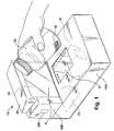
- FIG. 1is a perspective view of a bar code reader having a vertical and a horizontal window through which bar codes are viewed by multiple cameras within the reader constructed in accordance with one example embodiment of the present disclosure
- FIG. 2is a perspective view of the reader of FIG. 1 with a portion of the reader housing removed to illustrate a plurality of cameras located on a printed circuit board;
- FIG. 3is a perspective view of the reader of FIG. 1 showing additional cameras located on the printed circuit board shown in FIG. 2 ;
- FIG. 4is a plan view of a horizontal transparent window of an exemplary bar code reader
- FIG. 5is a schematic block diagram of selected systems and electrical circuitry of the bar code reader of FIG. 1 ;
- FIG. 6is a top plan view of the FIG. 1 exemplary bar code reader showing a portion of the reader field of view for viewing a top surface of a document that has been placed on a horizontal window;
- FIG. 7is a side elevation view of the FIG. 1 bar code reader illustrating a field of view for viewing a top surface of a document on a horizontal window;
- FIG. 8is a top plan view of the FIG. 1 exemplary bar code reader showing a portion of the reader field of view for viewing a bottom surface of a document placed on a horizontal window;
- FIG. 9is a side elevation view of the FIG. 1 bar code reader illustrating a field of view for viewing a bottom surface of a document on a horizontal window.
- FIG. 1depicts a stationary bar code reader 10 having an image and decoder system supported within an interior region 18 of a housing 20 .
- the housing 20may be integrated into a sales counter of a point of sales system that includes, for example, a cash register, a touch screen visual display or other type user interface and a printer for generating sales receipts.
- the housing 20 depicted in FIG. 1includes two transparent windows H, V so that objects moved or positioned outside the housing can be imaged.
- the housing 10 shown in FIG. 1has a boxlike base portion 10 A which supports the horizontal window and an upright portion 10 B which supports the vertical window V. The base and upright portions are attached to form a generally L shaped housing as seen from a side of the housing.
- multiple cameras C 1 -C 6are mounted to a printed circuit board 22 located inside the housing at a rear of the base portion 10 A.
- Each cameradefines a field-of-view FV 1 , FV 2 , FV 3 , FV 4 , FV 5 , FV 6 .
- Positioned behind and adjacent to the windows H, Vare reflective mirrors that define a given camera field-of-view such that the respective fields-of-view FV 1 -FV 6 pass from the housing 20 through the windows to create an effective total field-of-view (TFV) for the reader 10 in a region of the windows H, V, outside the housing 20 .
- each camera C 1 -C 6has an effective working range WR (shown schematically in FIG. 5 ) over which a target bar code 30 may be successfully imaged and decoded, there is an effective target area in front of the windows H, V within which an object 32 having a target bar code 30 can be presented or swiped for imaging and decoding.
- WRshown schematically
- either a sales person or a customerwill present or swipe a product or target object 32 selected for purchase in front of the windows.
- a target bar code 30 imprinted or affixed to the target object 32will be presented in or swiped through a region near the windows H, V for reading, that is, imaging and decoding of the coded indicia of the target bar code.
- the reader 10captures front and back images of the document.
- each camera assembly C 1 -C 6 of the imaging system 12captures a series of image frames of its respective field-of-view FV 1 -FV 6 .
- the series of image frames for each camera assembly C 1 -C 6is shown schematically as IF 1 , IF 2 , IF 3 , IF 4 , IF 5 , IF 6 in FIG. 5 .
- Each series of image frames IF 1 -IF 6comprises a sequence of individual image frames generated by the respective cameras C 1 -C 6 .
- the designation IF 1for example, represents multiple successive images obtained from the camera C 1 .
- the image frames IF 1 -IF 6are in the form of respective digital signals representative of raw gray scale values generated by each camera assembly C 1 -C 6 .
- Digital signals 35 that make up the framesare coupled to a bus interface 42 , where the signals are multiplexed by a multiplexer 43 and then communicated to a memory 44 in an organized fashion so that the processor knows which image representation belong to a given camera.
- the image processors 15access the image frames IF 1 -IF 6 from memory 44 and search for image frames that include an imaged target bar code 30 ′. If the imaged target bar code 30 ′ is present and decodable in one or more image frames, the decoder 16 attempts to decode the imaged target bar code 30 ′ using one or more of the image frames having the imaged target bar code 30 ′ or a portion thereof. If no bar code is present, the image processors look for documents within the image.
- Each cameraincludes a charged coupled device (CCD), a complementary metal oxide semiconductor (CMOS), or other imaging pixel array, operating under the control of the imaging processing system 14 .
- the sensor arraycomprises a two-dimensional (2D) CMOS array with a typical size of the pixel array being on the order of 752 ⁇ 480 pixels.
- the illumination-receiving pixels of the sensor arraydefine a sensor array surface secured to a printed circuit board for stability.
- the sensor array surfaceis substantially perpendicular to an optical axis of an imaging lens assembly, that is, a z axis that is perpendicular to the sensor array surface would be substantially parallel to the optical axis of a focusing lens.
- the pixels of the sensor array surfaceare disposed in an orthogonal arrangement of rows and columns of pixels.
- the reader circuitry 11includes imaging system 12 , the memory 44 and a power supply 11 a .
- the power supply 11 ais electrically coupled to and provides power to the circuitry 11 of the reader.
- the reader 10may include an illumination system 60 (shown schematically in FIG. 5 ) which provides illumination to illuminate the effective total field-of-view to facilitate obtaining an image 30 ′ of a target bar code 30 that has sufficient resolution and clarity for decoding.
- An exemplary systemhas light emitting diodes closely spaced from an associated charge coupled device for each of the cameras C 1 -C 6 . These LEDs are selectively activated to emit light under control of the processors 15 .
- the digital signals 35are received by the bus interface 42 of the image processing system 40 , which may include the multiplexer 43 , operating under the control of an application specific integrated circuit (ASIC) 46 , to serialize the image data contained in the digital signals 35 .
- the digitized values of the digitized signal 35are stored in the memory 44 .
- the digital values GSVconstitute a digitized version of the series of image frames IF 1 -IF 6 , which for each camera assembly C 1 -C 6 and for each image frame is representative of the image projected by the imaging lens assembly onto the pixel array during an exposure period. If the field-of-view of the imaging lens assembly includes the target bar code 30 , then a digital image 30 ′ of the target bar code 30 is obtained.
- the decoding circuitry 14operates in one or two modes controlled by a switch SW on the housing.
- the reader 10captures a series of images from the six camera assemblies and then retrieving an image from memory and determines if the image has a bar code. If so the processor 15 attempts to decode any decodable image within the image frame, e.g., the imaged target bar code 30 ′. If the decoding is successful, decoded data 56 , representative of the data/information coded in the target bar code 30 is then output 126 via a data output port 58 and/or displayed to a user of the reader 10 via a display output 59 .
- a speaker 34 b and/or an indicator LED 34 ais activated by the bar code reader circuitry 11 to indicate to the user that the target bar code 30 has been successfully read.
- the userIn document capture mode, the user will place a document to be imaged on the horizontal window H of the reader 10 and then actuates the switch SW to initiate document capture by the processor or processors 15 .
- the switch SWBy pressing a button switch SW on the reader of on a cash register (not shown) front and back document images are captured and stored until the check-cashing system to which the reader is connected, is ready to receive the image.
- the userplaces a check 100 onto the horizontal window with its long dimension aligned with the long dimension of the reader field of view.
- a typical check lengthis nearly as long as the long dimensions of the window H and marks M help the user properly align the check.
- Imaging the document after the user has placed it on the window and pressed the switch SWhelps assure that the check is static and properly positioned within the field of view of the imagers when the image is captured, so only a single, high quality image will be transmitted to a host computer.
- the reader 10may have an ability to read the MICR characters on the check using Optical Character Recognition (OCR).
- OCROptical Character Recognition
- OCROptical Character Recognition
- the readercan perform other image processing functions. For example, the reader can compare a signature to a signature in a database (typically stored in a remote computer). In other cases it may simply transmit the image to another computer.
- the processorhas already stored the front and back images of that document in memory. These image may be stored within the reader for batch transfer or may be immediately transmitted to a point of sale computer by means of the data output 58 .
- FIGS. 8 and 9show an imaging camera assembly C 2 ′ that captures images from objects from an angle from below the horizontal window H of the reader 10 . This allows the sensor array of the camera assembly C 2 ′ to see whatever is on the bottom of anything that rests on or is passed over the horizontal window.
- the imager field of view FV 2 ′is reflected off a mirror MB 2 to allow the optical system to fit in a housing that is not too deep for installation in a POS station.
- FIGS. 6 and 7show another imaging camera assembly C 5 looking downwards at the upper surface of the horizontal window H after reflecting off a mirror M 5 A.
- These two camera assembliesare positioned to enable scanning barcodes on the top and bottom of packages that are moved over the horizontal window. They also capturing images of a document, such as a check 100 ( FIG. 4 ), that is placed on the window H.
- the two camera assemblies working togethercan capture images of both sides of a check that is placed on the window H, as required by Check 21.
- An optical axis of these two camera assembliesis slanted with respect to the window, so any images that they might capture will show a slanted document, as opposed to s straight-on view as would be desirable.
- the angles at which the two imagers are positioned with respect to the windoware known, however, so the images can be de-tilted by processing of the images after they are captured.
- the reader 10then transmits undistorted images to the check processing system, just as the existing dedicated check scanners do.
- the imagers used in a scanner like this for barcode readingcan perform adequately with sensor arrays as small as around 752 ⁇ 480 pixels. This is known as a wide VGA sensor. This kind of sensor has the advantage of relatively high frame rates (60 frames per second), which facilitates the scanning of fast-moving barcodes. The relatively small array size also minimizes how much data must be processed to read a barcode, allowing for faster response from the barcode scanner and/or minimizing the cost of the image processing system. This relatively low resolution sensor, however, may not provide adequate resolution for a clear image of a check.
- the cameras C 2 ′, C 5are higher resolution sensors such as sensors with 1.2 to 1.3 megapixels. When barcodes are being scanned, these two cameras will also be used to perform that function. The increased resolution can be used to improve performance on barcodes with very narrow bars or spaces.
- a reduced resolution mode of image capturein which data from a subset of the pixels are read-out and processed. This low resolution mode has the advantage in this application of reducing image processing requirements and allowing higher frame rates.
- a 1.3 megapixel sensorcan operate at a frame rate of 30 frames/second at full resolution or at 60 frames/second at reduced resolution. A scanner that uses such a sensor can therefore operate the cameras at reduced resolution when reading barcodes that may be moving rapidly, or at full resolution to capture images of checks that are stationary on the window.
- Switching between these two modescan also be controlled by a host POS system or controller, which can signal via the input port 59 to the bar code reader 10 when to be in barcode reading mode and when to operate in document image capture mode. It may be desirable to alter the level of illumination supplied by the illumination system (made up of one or more LED per image system) in the scanner housing, depending on which mode is activated.
- the fields of view of cameras that capture the front and back sides of a documentmay not entirely cover the horizontal window. Markings M near the periphery of the window, or on the window itself indicate where the document 100 should be placed.
- the windows on barcode readers used in supermarkets and the likeoften become dirty or scuffed. This can interfere with the quality of the captured image.
- This dirtis stationary in every frame so the location of dirt in the image can be stored in the scanners memory allowing it to be subtracted from the image of the captured document.
- the scannercan recognize when dirt has accumulated and signal the operator to clean the window before capturing the image of a document.
- FIGS. 2 and 3depict an exemplary dual window bar code reader having a printed circuit board 22 that supports six imaging cameras assemblies. Additional details of this bar code reader are contained in pending U.S. patent application Ser. No. 12/266,642 having a filing date of Nov. 7, 2008 and which is incorporated herein by reference.
- Camera or imager C 1 and its associated opticsfaces generally vertically upward toward an inclined folding mirror MIA substantially directly overhead at a left side of the horizontal window H.
- the folding mirror M 1 Afaces another inclined narrow folding mirror M 1 B located at a right side of the horizontal window H.
- the folding mirror M 1 Bfaces still another inclined wide folding mirror M 1 C adjacent the mirror M 1 A.
- the folding mirror M 1 Cfaces out through the generally horizontal window H toward the right side of the dual window scanner such to form an imaging field-of-view.
- the camera or imager C 3 and its associated opticsare symmetrical with respect to a center line of the reader to imager C 1 .
- Camera C 3faces generally vertically upward toward an incline folding mirror M 3 A substantially directly overhead at a right side of the horizontal window H.
- the folding mirror M 3 Afaces another inclined narrow folding mirror M 3 B located at a left side of the horizontal window H.
- the folding mirror M 3 Bfaces still another inclined wide folding mirror M 3 C adjacent the mirror M 3 A.
- the folding mirror M 3 Cfaces out through the generally horizontal window H toward the left side of the dual window reader.
- Imager or camera C 2 and its associated opticsare located between imagers C 1 and C 3 and their associated optics.
- Imager C 2faces generally vertically upward toward an inclined folding mirror M 2 A substantially directly overhead generally centrally of the horizontal window H at one end thereof.
- the folding mirror M 2 Afaces another inclined folding mirror M 2 B located at the opposite end of the horizontal window H.
- the folding mirror M 2 Bfaces out through the window H in an upward direction toward the vertical window V in the housing 20 and as such can image a bottom side of a document such as the check 100 resting on the window H.
- the dual window readerhas a camera or imager C 4 and its associated optics faces generally vertically upward toward an incline folding mirror M 4 A substantially directly overhead at a left side of the vertical window V.
- the folding mirror M 4 Afaces another inclined narrow folding mirror M 4 B located at a right side of the vertical window V.
- the folding mirror M 4 Bfaces still another inclined wide folding mirror M 4 C adjacent the mirror M 4 A.
- the folding mirror M 4 Cfaces out through the generally vertical window V toward the right side of the dual window reader.
- camera or imager C 6 and its associated mirrorsare symmetrical to imager C 4 about a line extending through the center of the base portion 10 A of the reader housing 10 .
- the fold mirrors that define the field of view for this camera assembly C 6are deleted from this Figure for clarity.
- imager or camera C 5 and its associated opticsare located generally centrally between imagers C 4 and C 6 and their associated optics.
- Imager C 5faces generally vertically upward toward an inclined folding mirror M 5 A substantially directly overhead generally centrally of the vertical window V at one end thereof.
- the folding mirror M 5 Afaces out through the window V in a downward direction toward the horizontal window H in the housing 20 and captures images of a top surface of a document such as the check 100 resting on the top surface of the horizontal window H.
- the mirrorclips extraneous or unneeded light from a source such as a light emitting diode, it is commonly referred to as baffling.
- a sourcesuch as a light emitting diode
- three fold mirrorsare used to define a given field of view. Other numbers of mirrors, however, could be used to direct light to a field of view outside the housing.
Landscapes
- Physics & Mathematics (AREA)
- Engineering & Computer Science (AREA)
- Electromagnetism (AREA)
- Health & Medical Sciences (AREA)
- General Health & Medical Sciences (AREA)
- Toxicology (AREA)
- Artificial Intelligence (AREA)
- Computer Vision & Pattern Recognition (AREA)
- General Physics & Mathematics (AREA)
- Theoretical Computer Science (AREA)
- Facsimile Scanning Arrangements (AREA)
- Image Input (AREA)
Abstract
Description
Claims (23)
Priority Applications (2)
| Application Number | Priority Date | Filing Date | Title |
|---|---|---|---|
| US12/334,830US8079523B2 (en) | 2008-12-15 | 2008-12-15 | Imaging of non-barcoded documents |
| PCT/US2009/067816WO2010075016A1 (en) | 2008-12-15 | 2009-12-14 | Imaging of non-barcoded documents |
Applications Claiming Priority (1)
| Application Number | Priority Date | Filing Date | Title |
|---|---|---|---|
| US12/334,830US8079523B2 (en) | 2008-12-15 | 2008-12-15 | Imaging of non-barcoded documents |
Publications (2)
| Publication Number | Publication Date |
|---|---|
| US20100147953A1 US20100147953A1 (en) | 2010-06-17 |
| US8079523B2true US8079523B2 (en) | 2011-12-20 |
Family
ID=41786285
Family Applications (1)
| Application Number | Title | Priority Date | Filing Date |
|---|---|---|---|
| US12/334,830Active2030-03-06US8079523B2 (en) | 2008-12-15 | 2008-12-15 | Imaging of non-barcoded documents |
Country Status (2)
| Country | Link |
|---|---|
| US (1) | US8079523B2 (en) |
| WO (1) | WO2010075016A1 (en) |
Cited By (7)
| Publication number | Priority date | Publication date | Assignee | Title |
|---|---|---|---|---|
| US20090084854A1 (en)* | 2007-09-27 | 2009-04-02 | Symbol Technologies, Inc. | Multiple Camera Imaging-Based Bar Code Reader |
| US20100102129A1 (en)* | 2008-10-29 | 2010-04-29 | Symbol Technologies, Inc. | Bar code reader with split field of view |
| US20100116887A1 (en)* | 2008-11-07 | 2010-05-13 | Symbol Technologies, Inc. | Identification of non-barcoded products |
| US8389945B1 (en)* | 2011-08-25 | 2013-03-05 | Symbol Technologies, Inc. | Object detecting system in imaging-based barcode readers |
| USD709888S1 (en)* | 2012-07-02 | 2014-07-29 | Symbol Technologies, Inc. | Bi-optic imaging scanner module |
| USD723560S1 (en)* | 2013-07-03 | 2015-03-03 | Hand Held Products, Inc. | Scanner |
| EP4325626A4 (en)* | 2022-04-15 | 2024-10-16 | LG Energy Solution, Ltd. | BATTERY CELL TRACKING DEVICE |
Families Citing this family (42)
| Publication number | Priority date | Publication date | Assignee | Title |
|---|---|---|---|---|
| US8353457B2 (en)* | 2008-02-12 | 2013-01-15 | Datalogic ADC, Inc. | Systems and methods for forming a composite image of multiple portions of an object from multiple perspectives |
| EP2248069B1 (en) | 2008-02-12 | 2013-08-28 | Datalogic ADC, Inc. | Systems and methods for forming a composite image of multiple portions of an object from multiple perspectives |
| US8608076B2 (en)* | 2008-02-12 | 2013-12-17 | Datalogic ADC, Inc. | Monolithic mirror structure for use in a multi-perspective optical code reader |
| US8678287B2 (en)* | 2008-02-12 | 2014-03-25 | Datalogic ADC, Inc. | Two-plane optical code reader for acquisition of multiple views of an object |
| EP2335337B1 (en) | 2008-10-02 | 2020-03-11 | ecoATM, LLC | Secondary market and vending system for devices |
| US10853873B2 (en) | 2008-10-02 | 2020-12-01 | Ecoatm, Llc | Kiosks for evaluating and purchasing used electronic devices and related technology |
| US9881284B2 (en) | 2008-10-02 | 2018-01-30 | ecoATM, Inc. | Mini-kiosk for recycling electronic devices |
| US7881965B2 (en) | 2008-10-02 | 2011-02-01 | ecoATM, Inc. | Secondary market and vending system for devices |
| US11010841B2 (en) | 2008-10-02 | 2021-05-18 | Ecoatm, Llc | Kiosk for recycling electronic devices |
| US8322621B2 (en)* | 2008-12-26 | 2012-12-04 | Datalogic ADC, Inc. | Image-based code reader for acquisition of multiple views of an object and methods for employing same |
| US8261990B2 (en)* | 2008-12-26 | 2012-09-11 | Datalogic ADC, Inc. | Data reader having compact arrangement for acquisition of multiple views of an object |
| US8146821B2 (en)* | 2009-04-02 | 2012-04-03 | Symbol Technologies, Inc. | Auto-exposure for multi-imager barcode reader |
| US8464951B2 (en)* | 2009-10-29 | 2013-06-18 | Symbol Technologies, Inc. | Method and apparatus for monitoring an exit window of a scanner |
| DE202012013245U1 (en)* | 2011-04-06 | 2015-09-14 | ecoATM, Inc. | Automat for recycling electronic devices |
| US8939371B2 (en) | 2011-06-30 | 2015-01-27 | Symbol Technologies, Inc. | Individual exposure control over individually illuminated subfields of view split from an imager in a point-of-transaction workstation |
| JP5724771B2 (en)* | 2011-09-07 | 2015-05-27 | 株式会社デンソーウェーブ | Optical information reader |
| US8479995B2 (en)* | 2011-09-29 | 2013-07-09 | Ncr Corporation | Hybrid optical code scanner and system |
| US20150347798A1 (en)* | 2014-05-29 | 2015-12-03 | Symbol Technologies, Inc. | Point-of-transaction workstation for, and method of, imaging sheet-like targets |
| USD730901S1 (en)* | 2014-06-24 | 2015-06-02 | Hand Held Products, Inc. | In-counter barcode scanner |
| US9298957B2 (en)* | 2014-07-31 | 2016-03-29 | Symbol Technologies, Llc | Detecting window deterioration on barcode scanning workstation |
| US10401411B2 (en) | 2014-09-29 | 2019-09-03 | Ecoatm, Llc | Maintaining sets of cable components used for wired analysis, charging, or other interaction with portable electronic devices |
| ES2870629T3 (en) | 2014-10-02 | 2021-10-27 | Ecoatm Llc | App for device evaluation and other processes associated with device recycling |
| EP4446968A3 (en) | 2014-10-02 | 2024-12-25 | ecoATM, LLC | Wireless-enabled kiosk for recycling consumer devices |
| US10445708B2 (en) | 2014-10-03 | 2019-10-15 | Ecoatm, Llc | System for electrically testing mobile devices at a consumer-operated kiosk, and associated devices and methods |
| CA3056457A1 (en) | 2014-10-31 | 2016-05-06 | Mark Vincent Bowles | Systems and methods for recycling consumer electronic devices |
| US11080672B2 (en) | 2014-12-12 | 2021-08-03 | Ecoatm, Llc | Systems and methods for recycling consumer electronic devices |
| US10572946B2 (en) | 2014-10-31 | 2020-02-25 | Ecoatm, Llc | Methods and systems for facilitating processes associated with insurance services and/or other services for electronic devices |
| EP3215988A1 (en) | 2014-11-06 | 2017-09-13 | Ecoatm Inc. | Methods and systems for evaluating and recycling electronic devices |
| WO2016196175A1 (en)* | 2015-06-01 | 2016-12-08 | ecoATM, Inc. | Methods and systems for visually evaluating electronic devices |
| US10127647B2 (en) | 2016-04-15 | 2018-11-13 | Ecoatm, Llc | Methods and systems for detecting cracks in electronic devices |
| US9885672B2 (en) | 2016-06-08 | 2018-02-06 | ecoATM, Inc. | Methods and systems for detecting screen covers on electronic devices |
| US10269110B2 (en) | 2016-06-28 | 2019-04-23 | Ecoatm, Llc | Methods and systems for detecting cracks in illuminated electronic device screens |
| US12322259B2 (en) | 2018-12-19 | 2025-06-03 | Ecoatm, Llc | Systems and methods for vending and/or purchasing mobile phones and other electronic devices |
| EP3884475A1 (en) | 2018-12-19 | 2021-09-29 | ecoATM, LLC | Systems and methods for vending and/or purchasing mobile phones and other electronic devices |
| KR20210125526A (en) | 2019-02-12 | 2021-10-18 | 에코에이티엠, 엘엘씨 | Connector Carrier for Electronic Device Kiosk |
| EP3924918A1 (en) | 2019-02-12 | 2021-12-22 | ecoATM, LLC | Kiosk for evaluating and purchasing used electronic devices |
| CN111738402A (en) | 2019-02-18 | 2020-10-02 | 埃科亚特姆公司 | Neural network-based physical condition assessment of electronic equipment and related systems and methods |
| WO2021127291A2 (en) | 2019-12-18 | 2021-06-24 | Ecoatm, Llc | Systems and methods for vending and/or purchasing mobile phones and other electronic devices |
| US12271929B2 (en) | 2020-08-17 | 2025-04-08 | Ecoatm Llc | Evaluating an electronic device using a wireless charger |
| WO2022040668A1 (en) | 2020-08-17 | 2022-02-24 | Ecoatm, Llc | Evaluating an electronic device using optical character recognition |
| US11922467B2 (en) | 2020-08-17 | 2024-03-05 | ecoATM, Inc. | Evaluating an electronic device using optical character recognition |
| WO2022047473A1 (en) | 2020-08-25 | 2022-03-03 | Ecoatm, Llc | Evaluating and recycling electronic devices |
Citations (31)
| Publication number | Priority date | Publication date | Assignee | Title |
|---|---|---|---|---|
| US4613895A (en) | 1977-03-24 | 1986-09-23 | Eastman Kodak Company | Color responsive imaging device employing wavelength dependent semiconductor optical absorption |
| US4794239A (en) | 1987-10-13 | 1988-12-27 | Intermec Corporation | Multitrack bar code and associated decoding method |
| US5059779A (en) | 1989-06-16 | 1991-10-22 | Symbol Technologies, Inc. | Scan pattern generators for bar code symbol readers |
| US5124539A (en) | 1989-06-16 | 1992-06-23 | Symbol Technologies, Inc. | Scan pattern generators for bar code symbol readers |
| US5200599A (en) | 1989-06-16 | 1993-04-06 | Symbol Technologies, Inc | Symbol readers with changeable scan direction |
| US5304786A (en) | 1990-01-05 | 1994-04-19 | Symbol Technologies, Inc. | High density two-dimensional bar code symbol |
| US5559562A (en) | 1994-11-01 | 1996-09-24 | Ferster; William | MPEG editor method and apparatus |
| US5703349A (en) | 1995-06-26 | 1997-12-30 | Metanetics Corporation | Portable data collection device with two dimensional imaging assembly |
| US5717195A (en) | 1996-03-05 | 1998-02-10 | Metanetics Corporation | Imaging based slot dataform reader |
| EP1006475A2 (en) | 1998-11-19 | 2000-06-07 | Ncr International Inc. | Produce recognition system including a produce shape data collector |
| US6141062A (en) | 1998-06-01 | 2000-10-31 | Ati Technologies, Inc. | Method and apparatus for combining video streams |
| WO2001082214A1 (en) | 2000-02-28 | 2001-11-01 | Psc Scanning, Inc. | Multi-format bar code reader |
| US20030029915A1 (en) | 2001-06-15 | 2003-02-13 | Edward Barkan | Omnidirectional linear sensor-based code reading engines |
| US20030213841A1 (en)* | 2002-05-14 | 2003-11-20 | Josephson Stanley M. | Method for verifying and authenticating initially named payee of negotiable instruments |
| US20040146211A1 (en) | 2003-01-29 | 2004-07-29 | Knapp Verna E. | Encoder and method for encoding |
| US20050098633A1 (en) | 2000-09-06 | 2005-05-12 | Paul Poloniewicz | Zero-footprint camera-based point-of-sale bar code presentation scanning system |
| US6899272B2 (en)* | 2000-05-17 | 2005-05-31 | Symbol Technologies, Inc | Bioptics bar code reader |
| US6924807B2 (en) | 2000-03-23 | 2005-08-02 | Sony Computer Entertainment Inc. | Image processing apparatus and method |
| US20050259746A1 (en) | 2004-05-21 | 2005-11-24 | Texas Instruments Incorporated | Clocked output of multiple data streams from a common data port |
| US6991169B2 (en)* | 1992-07-14 | 2006-01-31 | Psc Scanning, Inc. | Multiple plane scanning system for data reading applications |
| US20060022051A1 (en) | 2004-07-29 | 2006-02-02 | Patel Mehul M | Point-of-transaction workstation for electro-optically reading one-dimensional and two-dimensional indicia by image capture |
| US20060043193A1 (en) | 2004-08-30 | 2006-03-02 | Brock Christopher W | Combination barcode imaging/decoding and real-time video capture system |
| US7076097B2 (en) | 2000-05-29 | 2006-07-11 | Sony Corporation | Image processing apparatus and method, communication apparatus, communication system and method, and recorded medium |
| US7116353B2 (en) | 1999-07-17 | 2006-10-03 | Esco Corporation | Digital video recording system |
| US7191947B2 (en) | 2004-07-23 | 2007-03-20 | Symbol Technologies, Inc. | Point-of-transaction workstation for electro-optical reading one-dimensional indicia, including image capture of two-dimensional targets |
| US20070079029A1 (en) | 2005-09-30 | 2007-04-05 | Symbol Technologies, Inc. | Processing image data from multiple sources |
| US7219831B2 (en)* | 2004-05-12 | 2007-05-22 | Seiko Epson Corporation | Check processing method, check processing program medium, and check processing apparatus |
| US7280124B2 (en) | 2004-08-11 | 2007-10-09 | Magna Donnelly Gmbh & Co. Kg | Vehicle with image processing system and method for operating an image processing system |
| US20080296382A1 (en) | 2007-05-31 | 2008-12-04 | Connell Ii Jonathan H | Smart scanning system |
| US7543747B2 (en)* | 2001-05-15 | 2009-06-09 | Hand Held Products, Inc. | Image capture apparatus and method |
| US7619527B2 (en)* | 2005-02-08 | 2009-11-17 | Datalogic Scanning, Inc. | Integrated data reader and electronic article surveillance (EAS) system |
- 2008
- 2008-12-15USUS12/334,830patent/US8079523B2/enactiveActive
- 2009
- 2009-12-14WOPCT/US2009/067816patent/WO2010075016A1/enactiveApplication Filing
Patent Citations (32)
| Publication number | Priority date | Publication date | Assignee | Title |
|---|---|---|---|---|
| US4613895A (en) | 1977-03-24 | 1986-09-23 | Eastman Kodak Company | Color responsive imaging device employing wavelength dependent semiconductor optical absorption |
| US4794239A (en) | 1987-10-13 | 1988-12-27 | Intermec Corporation | Multitrack bar code and associated decoding method |
| US5059779A (en) | 1989-06-16 | 1991-10-22 | Symbol Technologies, Inc. | Scan pattern generators for bar code symbol readers |
| US5124539A (en) | 1989-06-16 | 1992-06-23 | Symbol Technologies, Inc. | Scan pattern generators for bar code symbol readers |
| US5200599A (en) | 1989-06-16 | 1993-04-06 | Symbol Technologies, Inc | Symbol readers with changeable scan direction |
| US5304786A (en) | 1990-01-05 | 1994-04-19 | Symbol Technologies, Inc. | High density two-dimensional bar code symbol |
| US6991169B2 (en)* | 1992-07-14 | 2006-01-31 | Psc Scanning, Inc. | Multiple plane scanning system for data reading applications |
| US5559562A (en) | 1994-11-01 | 1996-09-24 | Ferster; William | MPEG editor method and apparatus |
| US5703349A (en) | 1995-06-26 | 1997-12-30 | Metanetics Corporation | Portable data collection device with two dimensional imaging assembly |
| US5717195A (en) | 1996-03-05 | 1998-02-10 | Metanetics Corporation | Imaging based slot dataform reader |
| US6141062A (en) | 1998-06-01 | 2000-10-31 | Ati Technologies, Inc. | Method and apparatus for combining video streams |
| EP1006475A2 (en) | 1998-11-19 | 2000-06-07 | Ncr International Inc. | Produce recognition system including a produce shape data collector |
| US7116353B2 (en) | 1999-07-17 | 2006-10-03 | Esco Corporation | Digital video recording system |
| WO2001082214A1 (en) | 2000-02-28 | 2001-11-01 | Psc Scanning, Inc. | Multi-format bar code reader |
| US6924807B2 (en) | 2000-03-23 | 2005-08-02 | Sony Computer Entertainment Inc. | Image processing apparatus and method |
| US6899272B2 (en)* | 2000-05-17 | 2005-05-31 | Symbol Technologies, Inc | Bioptics bar code reader |
| US7076097B2 (en) | 2000-05-29 | 2006-07-11 | Sony Corporation | Image processing apparatus and method, communication apparatus, communication system and method, and recorded medium |
| US20050098633A1 (en) | 2000-09-06 | 2005-05-12 | Paul Poloniewicz | Zero-footprint camera-based point-of-sale bar code presentation scanning system |
| US7543747B2 (en)* | 2001-05-15 | 2009-06-09 | Hand Held Products, Inc. | Image capture apparatus and method |
| US20030029915A1 (en) | 2001-06-15 | 2003-02-13 | Edward Barkan | Omnidirectional linear sensor-based code reading engines |
| US20030213841A1 (en)* | 2002-05-14 | 2003-11-20 | Josephson Stanley M. | Method for verifying and authenticating initially named payee of negotiable instruments |
| US20040146211A1 (en) | 2003-01-29 | 2004-07-29 | Knapp Verna E. | Encoder and method for encoding |
| US7219831B2 (en)* | 2004-05-12 | 2007-05-22 | Seiko Epson Corporation | Check processing method, check processing program medium, and check processing apparatus |
| US20050259746A1 (en) | 2004-05-21 | 2005-11-24 | Texas Instruments Incorporated | Clocked output of multiple data streams from a common data port |
| US7191947B2 (en) | 2004-07-23 | 2007-03-20 | Symbol Technologies, Inc. | Point-of-transaction workstation for electro-optical reading one-dimensional indicia, including image capture of two-dimensional targets |
| US20060022051A1 (en) | 2004-07-29 | 2006-02-02 | Patel Mehul M | Point-of-transaction workstation for electro-optically reading one-dimensional and two-dimensional indicia by image capture |
| US7280124B2 (en) | 2004-08-11 | 2007-10-09 | Magna Donnelly Gmbh & Co. Kg | Vehicle with image processing system and method for operating an image processing system |
| US20060043193A1 (en) | 2004-08-30 | 2006-03-02 | Brock Christopher W | Combination barcode imaging/decoding and real-time video capture system |
| US7619527B2 (en)* | 2005-02-08 | 2009-11-17 | Datalogic Scanning, Inc. | Integrated data reader and electronic article surveillance (EAS) system |
| US20070079029A1 (en) | 2005-09-30 | 2007-04-05 | Symbol Technologies, Inc. | Processing image data from multiple sources |
| US7430682B2 (en) | 2005-09-30 | 2008-09-30 | Symbol Technologies, Inc. | Processing image data from multiple sources |
| US20080296382A1 (en) | 2007-05-31 | 2008-12-04 | Connell Ii Jonathan H | Smart scanning system |
Non-Patent Citations (1)
| Title |
|---|
| International Search Report and Written Opinion dated Mar. 26, 2010 in related case PCT/US2009/067816. |
Cited By (12)
| Publication number | Priority date | Publication date | Assignee | Title |
|---|---|---|---|---|
| US20090084854A1 (en)* | 2007-09-27 | 2009-04-02 | Symbol Technologies, Inc. | Multiple Camera Imaging-Based Bar Code Reader |
| US8662397B2 (en) | 2007-09-27 | 2014-03-04 | Symbol Technologies, Inc. | Multiple camera imaging-based bar code reader |
| US20100102129A1 (en)* | 2008-10-29 | 2010-04-29 | Symbol Technologies, Inc. | Bar code reader with split field of view |
| US20100116887A1 (en)* | 2008-11-07 | 2010-05-13 | Symbol Technologies, Inc. | Identification of non-barcoded products |
| US8479996B2 (en) | 2008-11-07 | 2013-07-09 | Symbol Technologies, Inc. | Identification of non-barcoded products |
| US8389945B1 (en)* | 2011-08-25 | 2013-03-05 | Symbol Technologies, Inc. | Object detecting system in imaging-based barcode readers |
| USD709888S1 (en)* | 2012-07-02 | 2014-07-29 | Symbol Technologies, Inc. | Bi-optic imaging scanner module |
| USD723560S1 (en)* | 2013-07-03 | 2015-03-03 | Hand Held Products, Inc. | Scanner |
| USD766244S1 (en) | 2013-07-03 | 2016-09-13 | Hand Held Products, Inc. | Scanner |
| USD826233S1 (en) | 2013-07-03 | 2018-08-21 | Hand Held Products, Inc. | Scanner |
| EP4325626A4 (en)* | 2022-04-15 | 2024-10-16 | LG Energy Solution, Ltd. | BATTERY CELL TRACKING DEVICE |
| US12321816B2 (en) | 2022-04-15 | 2025-06-03 | Lg Energy Solution, Ltd. | Battery cell tracking device |
Also Published As
| Publication number | Publication date |
|---|---|
| US20100147953A1 (en) | 2010-06-17 |
| WO2010075016A1 (en) | 2010-07-01 |
Similar Documents
| Publication | Publication Date | Title |
|---|---|---|
| US8079523B2 (en) | Imaging of non-barcoded documents | |
| US8479997B2 (en) | Optical scanner with customer interface | |
| US20100001075A1 (en) | Multi-imaging scanner for reading images | |
| US8118227B2 (en) | Multiple camera imaging-based bar code reader with optimized imaging field | |
| US7757955B2 (en) | Bar code reader having multiple cameras | |
| US8622305B2 (en) | Efficient multi-image bar code reader | |
| JP4672725B2 (en) | Trading point workstation for electro-optic reading of one-dimensional marks, including image capture of two-dimensional targets | |
| US8146822B2 (en) | Exposure control for multi-imaging scanner | |
| US8479996B2 (en) | Identification of non-barcoded products | |
| US9129176B2 (en) | Method and apparatus for assembling an image of a document | |
| US20090020612A1 (en) | Imaging dual window scanner with presentation scanning | |
| US8613393B2 (en) | Optical scanner with customer interface | |
| US20100102129A1 (en) | Bar code reader with split field of view | |
| US8740075B2 (en) | Apparatus for and method of reading targets arbitrarily oriented in imaging workstations | |
| US8939371B2 (en) | Individual exposure control over individually illuminated subfields of view split from an imager in a point-of-transaction workstation | |
| US20080035732A1 (en) | Uniform illumination without specular reflection in imaging reader | |
| US8678274B1 (en) | Point-of-transaction checkout system for and method of processing targets electro-optically readable by a clerk-operated workstation and by a customer-operated accessory reader | |
| US20080296387A1 (en) | Point-of transaction workstation for electro-optically reading one-dimensional indicia, including image capture of two-dimensional targets | |
| US20090084856A1 (en) | Imaging reader with asymmetrical magnification | |
| US20120273572A1 (en) | Point-of-transaction workstation for and method of imaging indicia over full coverage scan zone occupied by unskewed subfields of view | |
| US8727218B1 (en) | Symmetric customer side scanner for bioptic rear tower | |
| US20080296388A1 (en) | Compact, ergonomic imaging reader and method | |
| US9038903B2 (en) | Method and apparatus for controlling illumination | |
| US9367721B2 (en) | Imaging optical code scanner with camera regions |
Legal Events
| Date | Code | Title | Description |
|---|---|---|---|
| AS | Assignment | Owner name:SYMBOL TECHNOLOGIES, INC.,NEW YORK Free format text:ASSIGNMENT OF ASSIGNORS INTEREST;ASSIGNOR:BARKAN, EDWARD D., MR.;REEL/FRAME:021982/0340 Effective date:20081212 Owner name:SYMBOL TECHNOLOGIES, INC., NEW YORK Free format text:ASSIGNMENT OF ASSIGNORS INTEREST;ASSIGNOR:BARKAN, EDWARD D., MR.;REEL/FRAME:021982/0340 Effective date:20081212 | |
| STCF | Information on status: patent grant | Free format text:PATENTED CASE | |
| AS | Assignment | Owner name:MORGAN STANLEY SENIOR FUNDING, INC. AS THE COLLATERAL AGENT, MARYLAND Free format text:SECURITY AGREEMENT;ASSIGNORS:ZIH CORP.;LASER BAND, LLC;ZEBRA ENTERPRISE SOLUTIONS CORP.;AND OTHERS;REEL/FRAME:034114/0270 Effective date:20141027 Owner name:MORGAN STANLEY SENIOR FUNDING, INC. AS THE COLLATE Free format text:SECURITY AGREEMENT;ASSIGNORS:ZIH CORP.;LASER BAND, LLC;ZEBRA ENTERPRISE SOLUTIONS CORP.;AND OTHERS;REEL/FRAME:034114/0270 Effective date:20141027 | |
| FPAY | Fee payment | Year of fee payment:4 | |
| AS | Assignment | Owner name:SYMBOL TECHNOLOGIES, LLC, NEW YORK Free format text:CHANGE OF NAME;ASSIGNOR:SYMBOL TECHNOLOGIES, INC.;REEL/FRAME:036083/0640 Effective date:20150410 | |
| AS | Assignment | Owner name:SYMBOL TECHNOLOGIES, INC., NEW YORK Free format text:RELEASE BY SECURED PARTY;ASSIGNOR:MORGAN STANLEY SENIOR FUNDING, INC.;REEL/FRAME:036371/0738 Effective date:20150721 | |
| MAFP | Maintenance fee payment | Free format text:PAYMENT OF MAINTENANCE FEE, 8TH YEAR, LARGE ENTITY (ORIGINAL EVENT CODE: M1552); ENTITY STATUS OF PATENT OWNER: LARGE ENTITY Year of fee payment:8 | |
| MAFP | Maintenance fee payment | Free format text:PAYMENT OF MAINTENANCE FEE, 12TH YEAR, LARGE ENTITY (ORIGINAL EVENT CODE: M1553); ENTITY STATUS OF PATENT OWNER: LARGE ENTITY Year of fee payment:12 |