US8079292B2 - Detection system for power equipment - Google Patents
Detection system for power equipmentDownload PDFInfo
- Publication number
- US8079292B2 US8079292B2US11/796,819US79681907AUS8079292B2US 8079292 B2US8079292 B2US 8079292B2US 79681907 AUS79681907 AUS 79681907AUS 8079292 B2US8079292 B2US 8079292B2
- Authority
- US
- United States
- Prior art keywords
- contact
- sensor
- signal
- machine
- blade
- Prior art date
- Legal status (The legal status is an assumption and is not a legal conclusion. Google has not performed a legal analysis and makes no representation as to the accuracy of the status listed.)
- Expired - Fee Related, expires
Links
- 238000001514detection methodMethods0.000titleclaimsabstractdescription54
- 230000008859changeEffects0.000claimsdescription11
- 238000000034methodMethods0.000claimsdescription3
- 238000006243chemical reactionMethods0.000abstractdescription30
- 230000009471actionEffects0.000abstractdescription4
- 239000003990capacitorSubstances0.000description49
- 238000010304firingMethods0.000description23
- 238000012544monitoring processMethods0.000description21
- 230000005284excitationEffects0.000description20
- 230000007246mechanismEffects0.000description20
- 239000002023woodSubstances0.000description17
- 230000006870functionEffects0.000description11
- 238000010586diagramMethods0.000description7
- 208000014674injuryDiseases0.000description7
- 208000027418Wounds and injuryDiseases0.000description6
- 230000006378damageEffects0.000description6
- 239000000463materialSubstances0.000description6
- 230000004913activationEffects0.000description5
- 229910052751metalInorganic materials0.000description5
- 239000002184metalSubstances0.000description5
- 230000004044responseEffects0.000description5
- 230000005355Hall effectEffects0.000description4
- 230000008901benefitEffects0.000description4
- 230000000452restraining effectEffects0.000description4
- 230000008878couplingEffects0.000description3
- 238000010168coupling processMethods0.000description3
- 238000005859coupling reactionMethods0.000description3
- 238000007599dischargingMethods0.000description3
- 230000000670limiting effectEffects0.000description3
- 238000012545processingMethods0.000description3
- 230000001360synchronised effectEffects0.000description3
- 230000001960triggered effectEffects0.000description3
- 239000004606Fillers/ExtendersSubstances0.000description2
- 239000004699Ultra-high molecular weight polyethyleneSubstances0.000description2
- 230000004888barrier functionEffects0.000description2
- 238000002955isolationMethods0.000description2
- 239000000155meltSubstances0.000description2
- 238000012986modificationMethods0.000description2
- 230000004048modificationEffects0.000description2
- 230000000737periodic effectEffects0.000description2
- 230000001105regulatory effectEffects0.000description2
- 230000007723transport mechanismEffects0.000description2
- 229920000785ultra high molecular weight polyethylenePolymers0.000description2
- 208000012260Accidental injuryDiseases0.000description1
- 239000004676acrylonitrile butadiene styreneSubstances0.000description1
- 230000003213activating effectEffects0.000description1
- 229910052782aluminiumInorganic materials0.000description1
- XAGFODPZIPBFFR-UHFFFAOYSA-NaluminiumChemical compound[Al]XAGFODPZIPBFFR-UHFFFAOYSA-N0.000description1
- 230000003321amplificationEffects0.000description1
- 230000002238attenuated effectEffects0.000description1
- 238000010276constructionMethods0.000description1
- 238000013016dampingMethods0.000description1
- 230000007423decreaseEffects0.000description1
- 230000001419dependent effectEffects0.000description1
- -1etc.Substances0.000description1
- 230000003203everyday effectEffects0.000description1
- 230000036039immunityEffects0.000description1
- 238000010348incorporationMethods0.000description1
- 238000002844meltingMethods0.000description1
- 230000008018meltingEffects0.000description1
- 229910001120nichromeInorganic materials0.000description1
- 238000003199nucleic acid amplification methodMethods0.000description1
- 239000004417polycarbonateSubstances0.000description1
- 229920000515polycarbonatePolymers0.000description1
- 230000005855radiationEffects0.000description1
- 230000002829reductive effectEffects0.000description1
- 230000002441reversible effectEffects0.000description1
- 230000035945sensitivityEffects0.000description1
- 238000009987spinningMethods0.000description1
- 229910001220stainless steelInorganic materials0.000description1
- 239000000758substrateSubstances0.000description1
- 238000012360testing methodMethods0.000description1
- 239000012815thermoplastic materialSubstances0.000description1
- 230000036346tooth eruptionEffects0.000description1
- 238000012546transferMethods0.000description1
- 230000001052transient effectEffects0.000description1
- 238000004804windingMethods0.000description1
Images


Classifications
- B—PERFORMING OPERATIONS; TRANSPORTING
- B26—HAND CUTTING TOOLS; CUTTING; SEVERING
- B26D—CUTTING; DETAILS COMMON TO MACHINES FOR PERFORATING, PUNCHING, CUTTING-OUT, STAMPING-OUT OR SEVERING
- B26D7/00—Details of apparatus for cutting, cutting-out, stamping-out, punching, perforating, or severing by means other than cutting
- B26D7/22—Safety devices specially adapted for cutting machines
- B26D7/24—Safety devices specially adapted for cutting machines arranged to disable the operating means for the cutting member
- B—PERFORMING OPERATIONS; TRANSPORTING
- B23—MACHINE TOOLS; METAL-WORKING NOT OTHERWISE PROVIDED FOR
- B23D—PLANING; SLOTTING; SHEARING; BROACHING; SAWING; FILING; SCRAPING; LIKE OPERATIONS FOR WORKING METAL BY REMOVING MATERIAL, NOT OTHERWISE PROVIDED FOR
- B23D47/00—Sawing machines or sawing devices working with circular saw blades, characterised only by constructional features of particular parts
- B23D47/02—Sawing machines or sawing devices working with circular saw blades, characterised only by constructional features of particular parts of frames; of guiding arrangements for work-table or saw-carrier
- B23D47/025—Sawing machines or sawing devices working with circular saw blades, characterised only by constructional features of particular parts of frames; of guiding arrangements for work-table or saw-carrier of tables
- B—PERFORMING OPERATIONS; TRANSPORTING
- B23—MACHINE TOOLS; METAL-WORKING NOT OTHERWISE PROVIDED FOR
- B23D—PLANING; SLOTTING; SHEARING; BROACHING; SAWING; FILING; SCRAPING; LIKE OPERATIONS FOR WORKING METAL BY REMOVING MATERIAL, NOT OTHERWISE PROVIDED FOR
- B23D47/00—Sawing machines or sawing devices working with circular saw blades, characterised only by constructional features of particular parts
- B23D47/08—Sawing machines or sawing devices working with circular saw blades, characterised only by constructional features of particular parts of devices for bringing the circular saw blade to the workpiece or removing same therefrom
- B—PERFORMING OPERATIONS; TRANSPORTING
- B23—MACHINE TOOLS; METAL-WORKING NOT OTHERWISE PROVIDED FOR
- B23D—PLANING; SLOTTING; SHEARING; BROACHING; SAWING; FILING; SCRAPING; LIKE OPERATIONS FOR WORKING METAL BY REMOVING MATERIAL, NOT OTHERWISE PROVIDED FOR
- B23D59/00—Accessories specially designed for sawing machines or sawing devices
- B23D59/001—Measuring or control devices, e.g. for automatic control of work feed pressure on band saw blade
- B—PERFORMING OPERATIONS; TRANSPORTING
- B27—WORKING OR PRESERVING WOOD OR SIMILAR MATERIAL; NAILING OR STAPLING MACHINES IN GENERAL
- B27B—SAWS FOR WOOD OR SIMILAR MATERIAL; COMPONENTS OR ACCESSORIES THEREFOR
- B27B13/00—Band or strap sawing machines; Components or equipment therefor
- B27B13/14—Braking devices specially designed for band sawing machines, e.g. acting after damage of the band saw blade
- B—PERFORMING OPERATIONS; TRANSPORTING
- B27—WORKING OR PRESERVING WOOD OR SIMILAR MATERIAL; NAILING OR STAPLING MACHINES IN GENERAL
- B27B—SAWS FOR WOOD OR SIMILAR MATERIAL; COMPONENTS OR ACCESSORIES THEREFOR
- B27B5/00—Sawing machines working with circular or cylindrical saw blades; Components or equipment therefor
- B27B5/29—Details; Component parts; Accessories
- B27B5/38—Devices for braking the circular saw blade or the saw spindle; Devices for damping vibrations of the circular saw blade, e.g. silencing
- B—PERFORMING OPERATIONS; TRANSPORTING
- B27—WORKING OR PRESERVING WOOD OR SIMILAR MATERIAL; NAILING OR STAPLING MACHINES IN GENERAL
- B27G—ACCESSORY MACHINES OR APPARATUS FOR WORKING WOOD OR SIMILAR MATERIALS; TOOLS FOR WORKING WOOD OR SIMILAR MATERIALS; SAFETY DEVICES FOR WOOD WORKING MACHINES OR TOOLS
- B27G19/00—Safety guards or devices specially adapted for wood saws; Auxiliary devices facilitating proper operation of wood saws
- B27G19/02—Safety guards or devices specially adapted for wood saws; Auxiliary devices facilitating proper operation of wood saws for circular saws
- B—PERFORMING OPERATIONS; TRANSPORTING
- B27—WORKING OR PRESERVING WOOD OR SIMILAR MATERIAL; NAILING OR STAPLING MACHINES IN GENERAL
- B27G—ACCESSORY MACHINES OR APPARATUS FOR WORKING WOOD OR SIMILAR MATERIALS; TOOLS FOR WORKING WOOD OR SIMILAR MATERIALS; SAFETY DEVICES FOR WOOD WORKING MACHINES OR TOOLS
- B27G19/00—Safety guards or devices specially adapted for wood saws; Auxiliary devices facilitating proper operation of wood saws
- B27G19/06—Safety guards or devices specially adapted for wood saws; Auxiliary devices facilitating proper operation of wood saws for band or strap saws
- F—MECHANICAL ENGINEERING; LIGHTING; HEATING; WEAPONS; BLASTING
- F16—ENGINEERING ELEMENTS AND UNITS; GENERAL MEASURES FOR PRODUCING AND MAINTAINING EFFECTIVE FUNCTIONING OF MACHINES OR INSTALLATIONS; THERMAL INSULATION IN GENERAL
- F16P—SAFETY DEVICES IN GENERAL; SAFETY DEVICES FOR PRESSES
- F16P3/00—Safety devices acting in conjunction with the control or operation of a machine; Control arrangements requiring the simultaneous use of two or more parts of the body
- F16P3/12—Safety devices acting in conjunction with the control or operation of a machine; Control arrangements requiring the simultaneous use of two or more parts of the body with means, e.g. feelers, which in case of the presence of a body part of a person in or near the danger zone influence the control or operation of the machine
- F16P3/14—Safety devices acting in conjunction with the control or operation of a machine; Control arrangements requiring the simultaneous use of two or more parts of the body with means, e.g. feelers, which in case of the presence of a body part of a person in or near the danger zone influence the control or operation of the machine the means being photocells or other devices sensitive without mechanical contact
- F16P3/148—Safety devices acting in conjunction with the control or operation of a machine; Control arrangements requiring the simultaneous use of two or more parts of the body with means, e.g. feelers, which in case of the presence of a body part of a person in or near the danger zone influence the control or operation of the machine the means being photocells or other devices sensitive without mechanical contact using capacitive technology
- G—PHYSICS
- G05—CONTROLLING; REGULATING
- G05B—CONTROL OR REGULATING SYSTEMS IN GENERAL; FUNCTIONAL ELEMENTS OF SUCH SYSTEMS; MONITORING OR TESTING ARRANGEMENTS FOR SUCH SYSTEMS OR ELEMENTS
- G05B9/00—Safety arrangements
- G05B9/02—Safety arrangements electric
- Y—GENERAL TAGGING OF NEW TECHNOLOGICAL DEVELOPMENTS; GENERAL TAGGING OF CROSS-SECTIONAL TECHNOLOGIES SPANNING OVER SEVERAL SECTIONS OF THE IPC; TECHNICAL SUBJECTS COVERED BY FORMER USPC CROSS-REFERENCE ART COLLECTIONS [XRACs] AND DIGESTS
- Y10—TECHNICAL SUBJECTS COVERED BY FORMER USPC
- Y10S—TECHNICAL SUBJECTS COVERED BY FORMER USPC CROSS-REFERENCE ART COLLECTIONS [XRACs] AND DIGESTS
- Y10S83/00—Cutting
- Y10S83/01—Safety devices
- Y—GENERAL TAGGING OF NEW TECHNOLOGICAL DEVELOPMENTS; GENERAL TAGGING OF CROSS-SECTIONAL TECHNOLOGIES SPANNING OVER SEVERAL SECTIONS OF THE IPC; TECHNICAL SUBJECTS COVERED BY FORMER USPC CROSS-REFERENCE ART COLLECTIONS [XRACs] AND DIGESTS
- Y10—TECHNICAL SUBJECTS COVERED BY FORMER USPC
- Y10T—TECHNICAL SUBJECTS COVERED BY FORMER US CLASSIFICATION
- Y10T83/00—Cutting
- Y10T83/04—Processes
- Y—GENERAL TAGGING OF NEW TECHNOLOGICAL DEVELOPMENTS; GENERAL TAGGING OF CROSS-SECTIONAL TECHNOLOGIES SPANNING OVER SEVERAL SECTIONS OF THE IPC; TECHNICAL SUBJECTS COVERED BY FORMER USPC CROSS-REFERENCE ART COLLECTIONS [XRACs] AND DIGESTS
- Y10—TECHNICAL SUBJECTS COVERED BY FORMER USPC
- Y10T—TECHNICAL SUBJECTS COVERED BY FORMER US CLASSIFICATION
- Y10T83/00—Cutting
- Y10T83/081—With randomly actuated stopping means
- Y10T83/088—Responsive to tool detector or work-feed-means detector
- Y10T83/089—Responsive to tool characteristic
- Y—GENERAL TAGGING OF NEW TECHNOLOGICAL DEVELOPMENTS; GENERAL TAGGING OF CROSS-SECTIONAL TECHNOLOGIES SPANNING OVER SEVERAL SECTIONS OF THE IPC; TECHNICAL SUBJECTS COVERED BY FORMER USPC CROSS-REFERENCE ART COLLECTIONS [XRACs] AND DIGESTS
- Y10—TECHNICAL SUBJECTS COVERED BY FORMER USPC
- Y10T—TECHNICAL SUBJECTS COVERED BY FORMER US CLASSIFICATION
- Y10T83/00—Cutting
- Y10T83/081—With randomly actuated stopping means
- Y10T83/091—Responsive to work sensing means
- Y—GENERAL TAGGING OF NEW TECHNOLOGICAL DEVELOPMENTS; GENERAL TAGGING OF CROSS-SECTIONAL TECHNOLOGIES SPANNING OVER SEVERAL SECTIONS OF THE IPC; TECHNICAL SUBJECTS COVERED BY FORMER USPC CROSS-REFERENCE ART COLLECTIONS [XRACs] AND DIGESTS
- Y10—TECHNICAL SUBJECTS COVERED BY FORMER USPC
- Y10T—TECHNICAL SUBJECTS COVERED BY FORMER US CLASSIFICATION
- Y10T83/00—Cutting
- Y10T83/141—With means to monitor and control operation [e.g., self-regulating means]
- Y—GENERAL TAGGING OF NEW TECHNOLOGICAL DEVELOPMENTS; GENERAL TAGGING OF CROSS-SECTIONAL TECHNOLOGIES SPANNING OVER SEVERAL SECTIONS OF THE IPC; TECHNICAL SUBJECTS COVERED BY FORMER USPC CROSS-REFERENCE ART COLLECTIONS [XRACs] AND DIGESTS
- Y10—TECHNICAL SUBJECTS COVERED BY FORMER USPC
- Y10T—TECHNICAL SUBJECTS COVERED BY FORMER US CLASSIFICATION
- Y10T83/00—Cutting
- Y10T83/162—With control means responsive to replaceable or selectable information program
- Y10T83/173—Arithmetically determined program
- Y10T83/175—With condition sensor
- Y10T83/178—Responsive to work
- Y—GENERAL TAGGING OF NEW TECHNOLOGICAL DEVELOPMENTS; GENERAL TAGGING OF CROSS-SECTIONAL TECHNOLOGIES SPANNING OVER SEVERAL SECTIONS OF THE IPC; TECHNICAL SUBJECTS COVERED BY FORMER USPC CROSS-REFERENCE ART COLLECTIONS [XRACs] AND DIGESTS
- Y10—TECHNICAL SUBJECTS COVERED BY FORMER USPC
- Y10T—TECHNICAL SUBJECTS COVERED BY FORMER US CLASSIFICATION
- Y10T83/00—Cutting
- Y10T83/525—Operation controlled by detector means responsive to work
- Y10T83/541—Actuation of tool controlled in response to work-sensing means
- Y—GENERAL TAGGING OF NEW TECHNOLOGICAL DEVELOPMENTS; GENERAL TAGGING OF CROSS-SECTIONAL TECHNOLOGIES SPANNING OVER SEVERAL SECTIONS OF THE IPC; TECHNICAL SUBJECTS COVERED BY FORMER USPC CROSS-REFERENCE ART COLLECTIONS [XRACs] AND DIGESTS
- Y10—TECHNICAL SUBJECTS COVERED BY FORMER USPC
- Y10T—TECHNICAL SUBJECTS COVERED BY FORMER US CLASSIFICATION
- Y10T83/00—Cutting
- Y10T83/606—Interrelated tool actuating means and guard means
- Y10T83/613—Work guard
- Y—GENERAL TAGGING OF NEW TECHNOLOGICAL DEVELOPMENTS; GENERAL TAGGING OF CROSS-SECTIONAL TECHNOLOGIES SPANNING OVER SEVERAL SECTIONS OF THE IPC; TECHNICAL SUBJECTS COVERED BY FORMER USPC CROSS-REFERENCE ART COLLECTIONS [XRACs] AND DIGESTS
- Y10—TECHNICAL SUBJECTS COVERED BY FORMER USPC
- Y10T—TECHNICAL SUBJECTS COVERED BY FORMER US CLASSIFICATION
- Y10T83/00—Cutting
- Y10T83/768—Rotatable disc tool pair or tool and carrier
- Y10T83/7684—With means to support work relative to tool[s]
- Y10T83/7693—Tool moved relative to work-support during cutting
- Y10T83/7697—Tool angularly adjustable relative to work-support
- Y—GENERAL TAGGING OF NEW TECHNOLOGICAL DEVELOPMENTS; GENERAL TAGGING OF CROSS-SECTIONAL TECHNOLOGIES SPANNING OVER SEVERAL SECTIONS OF THE IPC; TECHNICAL SUBJECTS COVERED BY FORMER USPC CROSS-REFERENCE ART COLLECTIONS [XRACs] AND DIGESTS
- Y10—TECHNICAL SUBJECTS COVERED BY FORMER USPC
- Y10T—TECHNICAL SUBJECTS COVERED BY FORMER US CLASSIFICATION
- Y10T83/00—Cutting
- Y10T83/768—Rotatable disc tool pair or tool and carrier
- Y10T83/7684—With means to support work relative to tool[s]
- Y10T83/7722—Support and tool relatively adjustable
- Y10T83/7726—By movement of the tool
- Y—GENERAL TAGGING OF NEW TECHNOLOGICAL DEVELOPMENTS; GENERAL TAGGING OF CROSS-SECTIONAL TECHNOLOGIES SPANNING OVER SEVERAL SECTIONS OF THE IPC; TECHNICAL SUBJECTS COVERED BY FORMER USPC CROSS-REFERENCE ART COLLECTIONS [XRACs] AND DIGESTS
- Y10—TECHNICAL SUBJECTS COVERED BY FORMER USPC
- Y10T—TECHNICAL SUBJECTS COVERED BY FORMER US CLASSIFICATION
- Y10T83/00—Cutting
- Y10T83/768—Rotatable disc tool pair or tool and carrier
- Y10T83/7734—With guard for tool
- Y—GENERAL TAGGING OF NEW TECHNOLOGICAL DEVELOPMENTS; GENERAL TAGGING OF CROSS-SECTIONAL TECHNOLOGIES SPANNING OVER SEVERAL SECTIONS OF THE IPC; TECHNICAL SUBJECTS COVERED BY FORMER USPC CROSS-REFERENCE ART COLLECTIONS [XRACs] AND DIGESTS
- Y10—TECHNICAL SUBJECTS COVERED BY FORMER USPC
- Y10T—TECHNICAL SUBJECTS COVERED BY FORMER US CLASSIFICATION
- Y10T83/00—Cutting
- Y10T83/768—Rotatable disc tool pair or tool and carrier
- Y10T83/7755—Carrier for rotatable tool movable during cutting
- Y10T83/7788—Tool carrier oscillated or rotated
- Y—GENERAL TAGGING OF NEW TECHNOLOGICAL DEVELOPMENTS; GENERAL TAGGING OF CROSS-SECTIONAL TECHNOLOGIES SPANNING OVER SEVERAL SECTIONS OF THE IPC; TECHNICAL SUBJECTS COVERED BY FORMER USPC CROSS-REFERENCE ART COLLECTIONS [XRACs] AND DIGESTS
- Y10—TECHNICAL SUBJECTS COVERED BY FORMER USPC
- Y10T—TECHNICAL SUBJECTS COVERED BY FORMER US CLASSIFICATION
- Y10T83/00—Cutting
- Y10T83/849—With signal, scale, or indicator
- Y10T83/85—Signal; e.g., alarm
- Y—GENERAL TAGGING OF NEW TECHNOLOGICAL DEVELOPMENTS; GENERAL TAGGING OF CROSS-SECTIONAL TECHNOLOGIES SPANNING OVER SEVERAL SECTIONS OF THE IPC; TECHNICAL SUBJECTS COVERED BY FORMER USPC CROSS-REFERENCE ART COLLECTIONS [XRACs] AND DIGESTS
- Y10—TECHNICAL SUBJECTS COVERED BY FORMER USPC
- Y10T—TECHNICAL SUBJECTS COVERED BY FORMER US CLASSIFICATION
- Y10T83/00—Cutting
- Y10T83/869—Means to drive or to guide tool
- Y10T83/8773—Bevel or miter cut
Definitions
- the present inventionrelates to detection of human contact and more particularly to a system for detecting human contact with a portion of a piece of power equipment.
- machinesTo protect the user against accidental injury in operational zones machines have been equipped with various systems to detect the presence of a user, or a user's extremity, in a dangerous area and take some precautionary action. For instance, some systems require a user to place each hand on a switch remote from the danger zone before the machine will operate. With proper placement of the switches, the user cannot have their hands in the danger zone and still actuate the machine. Unfortunately, users often bypass the switches and are injured as a result. Other systems utilize a radio frequency field to detect the proximity of a user to the operation area and inhibit operation if a human presence is detected. Still other systems utilize a conductive glove worn by a user. When the glove comes into contact with a dangerous element of the machine, the machine is stopped to minimize or eliminate injury.
- FIG. 1is a schematic block diagram of a machine with a fast-acting safety system according to the present invention.
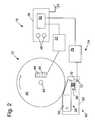
- FIG. 2is a schematic diagram of an exemplary safety system in the context of a machine having a circular blade.
- FIG. 3is a schematic circuit diagram of an electronic subsystem for the safety system of FIG. 1 , including an excitation system, a contact sense system and a firing system.
- FIG. 4is a schematic circuit diagram of a first alternative electronic subsystem for the safety system of FIG. 1 , including an excitation system, a contact sense system and a firing system.
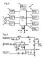
- FIG. 5is a block diagram illustrating the arrangement of a second alternative electronic subsystem.
- FIG. 6is a schematic diagram of an excitation system of the subsystem of FIG. 5 .
- FIG. 7shows an exemplary attenuation in signal that occurs when the finger of a user contacts a blade.
- FIG. 8is a schematic of a contact sense portion of the subsystem of FIG. 5 .
- FIG. 9is a schematic of a power supply of the subsystem of FIG. 5 .
- FIG. 10is a schematic of a boost regulator portion and a firing portion of the subsystem of FIG. 5 .
- FIG. 11is a schematic of a motor control portion of the subsystem of FIG. 5 .
- FIG. 12is a schematic of a rotation sensor portion of the subsystem of FIG. 5 .
- FIG. 13is a schematic of a user interface portion of the subsystem of FIG. 5 .
- FIG. 14is a block diagram of second and third alternative electronic subsystems.
- FIG. 15is a schematic of an excitation system portion of the subsystems of FIG. 14 .
- FIG. 16is a schematic of a contact sense portion of the second alternative subsystem of FIG. 14 .
- FIG. 17is a schematic of a contact sense portion of the third alternative subsystem of FIG. 14 .
- FIG. 18is a schematic of a power supply and firing system portion of the subsystems of FIG. 14 .
- Machine 10may be any of a variety of different machines adapted for cutting workpieces, such as wood, including a table saw, miter saw (chop saw), radial arm saw, circular saw, band saw, jointer, planer, etc.
- Machine 10includes an operative structure 12 having a cutting tool 14 and a motor assembly 16 adapted to drive the cutting tool.
- Machine 10also includes a safety system 18 configured to minimize the potential of a serious injury to a person using machine 10 .
- Safety system 18is adapted to detect the occurrence of one or more dangerous conditions during use of machine 10 . If such a dangerous condition is detected, safety system 18 is adapted to engage operative structure 12 to limit any injury to the user caused by the dangerous condition.
- Machine 10also includes a suitable power source 20 to provide power to operative structure 12 and safety system 18 .
- Power source 20may be an external power source such as line current, or an internal power source such as a battery.
- power source 20may include a combination of both external and internal power sources.
- power source 20may include two or more separate power sources, each adapted to power different portions of machine 10 .
- operative structure 12may take any one of many different forms, depending on the type of machine 10 .
- operative structure 12may include a stationary housing configured to support motor assembly 16 in driving engagement with cutting tool 14 .
- operative structure 12may include a movable structure configured to carry cutting tool 14 between multiple operating positions.
- operative structure 12may include one or more transport mechanisms adapted to convey a workpiece toward and/or away from cutting tool 14 .
- Motor assembly 16includes one or more motors adapted to drive cutting tool 14 .
- the motorsmay be either directly or indirectly coupled to the cutting tool, and may also be adapted to drive workpiece transport mechanisms.
- Cutting tool 14typically includes one or more blades or other suitable cutting implements that are adapted to cut or remove portions from the workpieces.
- the particular form of cutting tool 14will vary depending upon the various embodiments of machine 10 .
- cutting tool 14will typically include one or more circular rotating blades having a plurality of teeth disposed along the perimetrical edge of the blade.
- the cutting tooltypically includes a plurality of radially spaced-apart blades.
- the cutting toolincludes an elongate, circuitous tooth-edged band.
- Safety system 18includes a detection subsystem 22 , a reaction subsystem 24 and a control subsystem 26 .
- Control subsystem 26may be adapted to receive inputs from a variety of sources including detection subsystem 22 , reaction subsystem 24 , operative structure 12 and motor assembly 16 .
- the control subsystemmay also include one or more sensors adapted to monitor selected parameters of machine 10 .
- control subsystem 26typically includes one or more instruments operable by a user to control the machine.
- the control subsystemis configured to control machine 10 in response to the inputs it receives.
- Detection subsystem 22is configured to detect one or more dangerous, or triggering, conditions during use of machine 10 .
- the detection subsystemmay be configured to detect that a portion of the user's body is dangerously close to, or in contact with, a portion of cutting tool 14 .
- the detection subsystemmay be configured to detect the rapid movement of a workpiece due to kickback by the cutting tool, as is described in U.S. Provisional Patent Application Ser. No. 60/182,866, filed Feb. 16, 2000, the disclosure of which is herein incorporated by reference.
- detection subsystem 22may inform control subsystem 26 of the dangerous condition, which then activates reaction subsystem 24 .
- the detection subsystemmay be adapted to activate the reaction subsystem directly.
- reaction subsystem 24is configured to engage operative structure 12 quickly to prevent serious injury to the user. It will be appreciated that the particular action to be taken by reaction subsystem 24 will vary depending on the type of machine 10 and/or the dangerous condition that is detected. For example, reaction subsystem 24 may be configured to do one or more of the following: stop the movement of cutting tool 14 , disconnect motor assembly 16 from power source 20 , place a barrier between the cutting tool and the user, or retract the cutting tool from its operating position, etc. The reaction subsystem may be configured to take a combination of steps to protect the user from serious injury. Placement of a barrier between the cutting tool and teeth is described in more detail in U.S. Provisional Patent Application Ser. No. 60/225,206, filed Aug.
- reaction subsystem 24typically will vary depending on which action(s) are taken.
- reaction subsystem 24is configured to stop the movement of cutting tool 14 and includes a brake mechanism 28 , a biasing mechanism 30 , a restraining mechanism 32 , and a release mechanism 34 .
- Brake mechanism 28is adapted to engage operative structure 12 under the urging of biasing mechanism 30 .
- restraining mechanism 32holds the brake mechanism out of engagement with the operative structure.
- the brake mechanismupon receipt of an activation signal by reaction subsystem 24 , the brake mechanism is released from the restraining mechanism by release mechanism 34 , whereupon, the brake mechanism quickly engages at least a portion of the operative structure to bring the cutting tool to a stop.
- FIG. 2one example of the many possible implementations of safety system 18 is shown.
- System 18is configured to engage an operative structure having a cutting tool in the form of a circular blade 40 mounted on a rotating shaft or arbor 42 .
- Blade 40includes a plurality of cutting teeth (not shown) disposed around the outer edge of the blade.
- brake mechanism 28is adapted to engage the teeth of blade 40 and stop the rotation of the blade.
- detection subsystem 22is adapted to detect the dangerous condition of the user coming into contact with blade 40 .
- the detection subsystemincludes a sensor assembly, such as contact detection plates 44 and 46 , capacitively coupled to blade 40 to detect any contact between the user's body and the blade.
- the blade, or some larger portion of cutting tool 14is electrically isolated from the remainder of machine 10 .
- detection subsystem 22may include a different sensor assembly configured to detect contact in other ways, such as optically, resistively, etc.
- the detection subsystemis adapted to transmit a signal to control subsystem 26 . When contact between the user and the blade is detected.
- Various exemplary embodiments and implementations of detection subsystem 22are described in more detail below, and in U.S. Provisional Patent Application Ser. No. 60/225,211, filed Aug. 14, 2000, the disclosure of which is herein incorporated by reference.
- Control subsystem 26includes one or more instruments 48 that are operable by a user to control the motion of blade 40 .
- Instruments 48may include start/stop switches, speed controls, direction controls, etc.
- Control subsystem 26also includes a logic controller 50 connected to receive the user's inputs via instruments 48 .
- Logic controller 50is also connected to receive a contact detection signal from detection subsystem 22 . Further, the logic controller may be configured to receive inputs from other sources (not shown) such as blade motion sensors, workpiece sensors, etc. In any event, the logic controller is configured to control operative structure 12 in response to the user's inputs through instruments 48 .
- control subsystem 26upon receipt of a contact detection signal from detection subsystem 22 , the logic controller overrides the control inputs from the user and activates reaction subsystem 24 to stop the motion of the blade.
- control subsystem 26Various exemplary embodiments and implementations of control subsystem 26 are described in more detail in U.S. Provisional Patent Application Ser. No. 60/225,059, filed Aug. 14, 2000, and U.S. Provisional Patent Application Ser. No. 60/225,094, filed Aug. 14, 2000, the disclosures of which are herein incorporated by reference.
- brake mechanism 28includes a pawl 60 mounted adjacent the edge of blade 40 and selectively moveable to engage and grip the teeth of the blade.
- Pawl 60may be constructed of any suitable material adapted to engage and stop the blade.
- the pawlmay be constructed of a relatively high strength thermoplastic material such as polycarbonate, ultrahigh molecular weight polyethylene (UHMW) or Acrylonitrile Butadiene Styrene (ABS), etc., or a metal such as aluminum, etc. It will be appreciated that the construction of pawl 60 will vary depending on the configuration of blade 40 . In any event, the pawl is urged into the blade by a biasing mechanism in the form of a spring 66 .
- pawl 60is pivoted into the teeth of blade 40 . It should be understood that sliding or rotary movement of pawl 60 might also be used.
- the springis adapted to urge pawl 60 into the teeth of the blade with sufficient force to grip the blade and quickly bring it to a stop.
- the pawlis held away from the edge of the blade by a restraining mechanism in the form of a fusible member 70 .
- the fusible memberis constructed of a suitable material adapted to restrain the pawl against the bias of spring 66 , and also adapted to melt under a determined electrical current density. Examples of suitable materials for fusible member 70 include NiChrome wire, stainless steel wire, etc.
- the fusible memberis connected between the pawl and a contact mount 72 .
- fusible member 70holds the pawl relatively close to the edge of the blade to reduce the distance the pawl must travel to engage the blade. Positioning the pawl relatively close to the edge of the blade reduces the time required for the pawl to engage and stop the blade.
- the pawlis held approximately 1/32-inch to 1 ⁇ 4-inch from the edge of the blade by fusible member 70 , however other pawl-to-blade spacings may also be used within the scope of the invention.
- Pawl 60is released from its unactuated, or cocked, position to engage blade 40 by a release mechanism in the form of a firing subsystem 76 .
- the firing subsystemis coupled to contact mount 72 , and is configured to melt fusible member 70 by passing a surge of electrical current through the fusible member.
- Firing subsystem 76is coupled to logic controller 50 and activated by a signal from the logic controller. When the logic controller receives a contact detection signal from detection subsystem 22 , the logic controller sends an activation signal to firing subsystem 76 , which melts fusible member 70 , thereby releasing the pawl to stop the blade.
- reaction subsystem 24are described in more detail in U.S. Provisional Patent Application Ser. No.
- safety system 18includes a replaceable cartridge 80 having a housing 82 .
- Pawl 60 , spring 66 , fusible member 70 and contact mount 72are all mounted within housing 82 .
- other portions of safety system 18may be mounted within the housing.
- safety system 18may be replaced separately or reused as appropriate.
- Various exemplary embodiments and implementations of a safety system using a replaceable cartridgeare described in more detail in U.S. Provisional Patent Application Ser. No. 60/225,201, filed Aug. 14, 2000, and U.S. Provisional Patent Application Ser. No. 60/225,212, filed Aug. 14, 2000, the disclosures of which are herein incorporated by reference.
- safety system 18While one particular implementation of safety system 18 has been described, it will be appreciated that many variations and modifications are possible within the scope of the invention. Many such variations and modifications are described in U.S. Provisional Patent Application Ser. No. 60/182,866, filed Feb. 16, 2000 and U.S. Provisional Patent Application Ser. No. 60/157,340, filed Oct. 1, 1999, the disclosures of which are herein incorporated by reference.
- Electronic subsystem 100is adapted to work with the two-plate capacitive coupling system described in U.S. Provisional Patent Application Ser. No. 60/225,211, filed Aug. 14, 2000.
- Electronic subsystem 100includes an excitation system 101 and a monitoring or contact sensing system 102 .
- the exemplary configuration of electronic subsystem 100 illustrated in FIG. 3is just one of many configurations which may be used. Thus, it will be understood that any suitable embodiment or configuration could be used within the scope of the invention.
- excitation system 101includes an oscillator circuit that generates a wave input signal, such as a square wave signal, at a frequency of approximately 200 khz and voltage amplitude of 12 volts.
- excitation system 101may be configured to generate a signal of a different frequency and/or a different amplitude and/or different waveform.
- the oscillatoris formed by a pair of inverters 103 , 104 from a CD4040 configured as a bistable oscillator.
- the output of inverter 103is connected to a 100 pF capacitor 105 , which is connected through a 100 k ⁇ resistor 106 to the input of inverter 104 .
- a 10 k ⁇ resistor 107is connected between the output of inverter 104 and the junction between capacitor 105 and resistor 106 .
- the output of inverter 104is connected to the input of inverter 103 .
- a 10 k ⁇ resistor 108connects the output of inverter 103 to the input of another inverter 109 , which serves as an output buffer to drive the input wave signal onto the blade.
- a 2 k ⁇ series resistor 110functions to reduce any ringing in the input signal by damping the high frequency components of the signal.
- the particular form of the oscillator signalmay vary and there are many suitable waveforms and frequencies that may be utilized.
- the waveformmay be chosen to maximize the signal-to-noise ratio, for example, by selecting a frequency at which the human body has the lowest resistance or highest capacitance relative to the workpiece being cut.
- the signalcan be made asymmetric to take advantage of potentially larger distinctions between the electrical properties of human bodies and green wood at high frequency without substantially increasing the radio-frequency power radiated. For instance, utilizing a square wave with a 250 khz frequency, but a duty cycle of five percent, results in a signal with ten times higher frequency behavior than the base frequency, without increasing the radio-frequency energy radiation.
- there are many different oscillator circuitsthat are well known in the art and which would also be suitable for generating the excitation signal.
- the input signal generated by the oscillatoris fed through a shielded cable 111 onto charge plate 44 .
- Shielded cable 111functions to insulate the input signal from any electrical noise present in the operating environment, insuring that a “clean” input signal is transmitted onto charge plate 44 .
- the shielded cablereduces cross talk between the drive signal and the detected signal that might otherwise occur should the cables run close together.
- monitoring system 102may include a filter to remove any noise in the input signal or other electrical noise detected by charge plate 46 .
- Shielded cable 111also reduces radio-frequency emissions relative to an unshielded cable.
- the input signalis coupled from charge plate 44 to charge plate 46 via blade 40 .
- the signal received on charge plate 46is then fed via shielded cable 112 to monitoring system 102 .
- the monitoring systemis configured to detect a change in the signal due to contact between the user's body and the blade.
- monitoring system 102may be implemented in any of a wide variety of designs and configurations.
- monitoring system 102compares the amplitude of the input signal received at charge plate 46 to a determined reference voltage. In the event that the input signal received at charge plate 46 falls below the reference voltage for a determined time, the monitoring system produces an output signal to reaction subsystem 24 .
- the reaction subsystemis configured to receive the output signal and immediately act to stop the blade.
- shielded cable 112is connected between charge plate 46 and a voltage divider 113 .
- Voltage divider 113is formed by two 1 M ⁇ resistors 114 , 115 connected in series between the supply voltage (typically about 12 volts) and ground. The voltage divider functions to bias the output signal from charge plate 46 to an average level of half of the supply voltage. The biased signal is fed to the positive input of an op-amp 116 .
- Op-amp 116may be any one of many suitable op-amps that are well known in the art.
- op-ampis a TL082 op-amp.
- the negative input of the op-ampis fed by a reference voltage source 117 .
- the reference voltage sourceis formed by a 10 k ⁇ potentiometer 118 coupled in series between two 10 k ⁇ resistors 119 , 120 , which are connected to ground and the supply voltage, respectively.
- a 0.47 ⁇ F capacitor 121stabilizes the output of the reference voltage.
- op-amp 116functions as a comparator of the input signal and the reference voltage.
- the voltage referenceis adjusted so that its value is slightly less than the maximum input signal voltage from charge plate 46 .
- the output of the op-ampis low when the signal voltage from the charge plate is less than the reference voltage and high when the signal voltage from the charge plate is greater than the reference voltage.
- the input signalis a periodic signal such as the square wave generated by excitation system 101
- the output of op-amp 116will be a similar periodic signal.
- the maximum input signal voltagedecreases below the reference voltage and the op-amp output no longer goes high.
- the output of op-amp 116is coupled to a charging circuit 122 .
- Charging circuit 122includes a 240 ppF capacitor 123 that is connected between the output of op-amp 116 and ground.
- a 100 k ⁇ discharge resistor 124is connected in parallel to capacitor 123 .
- capacitor 123When the output of op-amp 116 is high, capacitor 123 is charged. Conversely, when the output of op-amp 116 is low, the charge from capacitor 123 discharges through resistor 124 with a time constant of approximately 24 ⁇ s. Thus, the voltage on capacitor 123 will discharge to less than half the supply voltage in approximately 25-50 ⁇ s unless the capacitor is recharged by pulses from the op-amp.
- a diode 125prevents the capacitor from discharging into op-amp 116 .
- Diode 125may be any one of many suitable diodes that are well known in the art, such as a 1N914 diode. It will be appreciated that the time required for capacitor 123 to discharge may be adjusted by selecting a different value capacitor or a different value resistor 124 .
- charging circuit 122will be recharged repeatedly and the voltage across capacitor 123 will remain high so long as the detected signal is received substantially unattenuated from its reference voltage at op-amp 116 .
- the voltage from capacitor 123is applied to the negative input of an op-amp 126 .
- Op-amp 126may be any one of many suitable op-amps, which are well known in the art, such as a TL082 op-amp.
- the positive input of op-amp 126is tied to a reference voltage, which is approximately equal to one-half of the supply voltage. In the exemplary embodiment depicted in FIG. 3 , the reference voltage is provided by reference voltage source 117 .
- the output of op-amp 126will be low. However, if the output of op-amp 116 does not go high for a period of 25-50 ⁇ s, the voltage across capacitor 123 will decay to less than the reference voltage, and op-amp 126 will output a high signal indicating contact between the user's body and the blade.
- the output signal from op-amp 126is coupled to actuate reaction subsystem 24 and stop the blade. The time between contact and activation of the reaction system can be adjusted by selecting the time constant of capacitor 123 and resistor 124 .
- the electrical contact between the operator and bladewill often be intermittent.
- the length of the contact and non-contact periodswill depend on such factors as the number of teeth on the blade and the speed of rotation of the blade.
- the charging circuitis configured to decay within approximately 25-50 ⁇ s to ensure that monitoring system 102 responds to even momentary contact between the user's body and the blade.
- the oscillatoris configured to create a 200 khz signal with pulses approximately every 5 ⁇ s. As a result, several pulses of the input signal occur during each period of contact, thereby increasing the reliability of contact detection.
- the oscillator and charging circuitmay be configured to cause the detection system to respond more quickly or more slowly. Generally, it is desirable to maximize the reliability of the contact detection, while minimizing the likelihood of erroneous detections.
- monitoring system 102typically is configured to detect contact periods as short as 25-50 ⁇ s, once the first tooth of the blade passes by the user's body, the contact signal received by the second electrical circuit may return to normal until the next tooth contacts the user's body. As a result, while the output signal at op-amp 126 will go high as a result of the first contact, the output signal may return low once the first contact ends. As a result, the output signal may not remain high long enough to activate the reaction system. For instance, if the output signal does not remain high long enough to actuate firing subsystem 76 , fusible member 70 may not melt.
- monitoring system 102may include a pulse extender in the form of charging circuit 127 on the output of op-amp 126 , similar to charging circuit 122 .
- charging circuit 127functions to ensure that the output signal remains high long enough to sufficiently discharge the charge storage devices to melt the fusible member.
- charging circuit 127includes a 0.47 ⁇ F capacitor 128 connected between the output of op-amp 126 and ground. When the output of op-amp 126 goes high, capacitor 128 charges to the output signal level. If the output of op-amp 126 returns low, the voltage across capacitor 128 discharges through 10 k resistor 129 with a time constant of approximately 4.7 ms.
- a diode 130such as an 1N914 diode, prevents capacitor 128 from discharging through op-amp 126 .
- the pulse extenderinsures that even a short contact with a single tooth will result in activation of the reaction system.
- a brakecan be released in approximately less than 100 ⁇ s and as little as 20 ⁇ s.
- the brakecontacts the blade in approximately one to approximately three milliseconds.
- the bladewill normally come to rest within not more than 2-10 ms of brake engagement. As a result, injury to the operator is minimized in the event of accidental contact with the cutting tool. With appropriate selection of components, it may be possible to stop the blade within 2 ms, or less.
- excitation system 101 and monitoring system 102have been described above with specific components having specific values and arranged in a specific configuration, it will be appreciated that these systems may be constructed with many different configurations, components, and values as necessary or desired for a particular application.
- the above configurations, components, and valuesare presented only to describe one particular embodiment that has proven effective, and should be viewed as illustrating, rather than limiting, the invention.
- FIG. 4shows alternative embodiments of excitation system 101 and monitoring system 102 , as well as firing system 76 , which is described in more detail in U.S. Provisional Patent Application Ser. No. 60/225,056, filed Aug. 14, 2000.
- Alternative excitation system 101is configured to generate a square wave signal using only a single comparator 133 such as an LM393 comparator.
- a 1M resistor 134is connected between the high input terminal of comparator 133 and ground.
- Another 1M resistor 135is connected between the high input terminal of comparator 133 and a low voltage supply V.
- a 1M resistor 136is connected between the high input terminal of the comparator and the output of the comparator.
- a 100 pF capacitor 137is connected between the low input terminal of the comparator and ground.
- a 27 k resistor 138is connected between the low input terminal of the comparator and the output of the comparator.
- a 3.3 k resistor 139is connected between the low voltage supply V and the output of the comparator.
- the alternative oscillator circuit illustrated in FIG. 6produces a square wave having a frequency of approximately 3-500 khz.
- a 1 k resistor 140is connected between the output of the comparator and shielded cable 111 to reduce ringing. It will be appreciated that the values of one or more elements of alternative excitation system 101 may be varied to produce a signal having a different frequency, waveform, etc.
- the signal generated by alternative excitation system 101is fed through shielded cable 111 to charge plate 44 .
- the signalis capacitively coupled to charge plate 46 via blade 40 .
- Alternative monitoring system 102receives the signal from charge plate 46 via shielded cable 112 and compares the signal to a reference voltage. If the signal falls below the reference voltage for approximately 25 ⁇ s, an output signal is generated indicating contact between the blade and the user's body.
- Alternative monitoring system 102includes a voltage divider 113 , which is formed of 22 k resistors 141 and 142 .
- the voltage dividerbiases the signal received via cable 112 to half the low voltage supply V.
- the lower resistance of resistors 141 , 142 relative to resistors 114 , 115serves to reduce 60 hz noise because low-frequency signals are attenuated.
- the biased signalis fed to the negative input terminal of a second comparator 143 , such as an LM393 comparator.
- the positive terminal of comparator 143is connected to reference voltage source 144 .
- the reference voltage sourceis formed by a 10 k ⁇ potentiometer 145 coupled in series between two 100 k ⁇ resistors 146 , 147 connected to the low voltage supply V and ground, respectively.
- a 0.1 ⁇ F capacitor 148stabilizes the output of the reference voltage.
- the reference voltageis used to adjust the trigger point.
- the output of second comparator 143is connected to the base terminal of an NPN bipolar junction transistor 149 , such as a 2N3904 transistor.
- the base terminal of transistor 149is also connected to low voltage supply V through a 100 k resistor 150 , and to ground through a 220 pF capacitor 151 .
- Potentiometer 145is adjusted so that the voltage at the positive terminal of comparator 143 is slightly lower than the high peak of the signal received at the negative terminal of the second comparator when there is no contact between the blade and the user's body. Thus, each high cycle of the signal causes the second comparator output to go low, discharging capacitor 151 .
- the output of the second comparatorcontinues to go low, preventing capacitor 151 from charging up through resistor 150 and switching transistor 149 on.
- the signal received at the negative terminal of the second comparatorremains below the reference voltage at the positive terminal and the output of the second comparator remains high.
- capacitor 151is able to charge up through resistor 150 and switch transistor 149 on.
- the collector terminal of transistor 149is connected to low voltage supply V, while the emitter terminal is connected to 680 ⁇ resistor 152 .
- transistor 149When transistor 149 is switched on, it supplies an output signal through resistor 152 of approximately 40 mA, which is fed to alternative firing system 76 .
- the alternative firing circuitincludes fusible member 70 connected between a high voltage supply HV and an SCR 613 , such as an NTE 5552 SCR. The gate terminal of the SCR is connected to resistor 152 .
- FIG. 4also illustrates an exemplary electrical supply system 154 configured to provide both low voltage supply V and high voltage supply HV from standard 120 VAC line voltage.
- Electrical supply system 154is connected to provide low voltage supply V and high voltage supply HV to alternative excitation system 101 , alternative monitoring system 102 , and alternative firing system 76 .
- the line voltageis connected through a 100 ⁇ resistor 155 and a diode 156 , such as a 1N4002 diode, to a 1000 ⁇ F charge storage capacitor 157 .
- the diodepasses only the positive portion of the line voltage, thereby charging capacitor 157 to approximately 160 V relative to ground.
- the positive terminal of capacitor 157serves as the high voltage supply HV connected to fusible link 70 .
- capacitor 157When SCR 613 is switched on upon detection of contact between the blade and the user's body, the charge stored in capacitor 157 is discharged through the fusible link until it melts. It will be appreciated that the size of capacitor 157 may be varied as required to supply the necessary current to melt fusible member 70 . As described in U.S. Provisional Patent Application Ser. No. 60/225,056, filed Aug. 14, 2000, use of a HV capacitor leads to a much higher current surge, and therefore a faster melting of the fusible member than is the case with a low voltage system.
- the positive terminal of capacitor 157also provides a transformer-less source of voltage for low voltage supply V, which includes a 12 k resistor 158 connected between the positive terminal of capacitor 157 and a reverse 40 V Zener diode 159 .
- Diode 159functions to maintain a relatively constant 40 V potential at the junction between the diode and resistor 158 . It can be seen that the current through the 12 k resistor will be about 10 mA. Most of this current is used by the low voltage circuit, which has a relatively constant current demand of about 8 mA. Note that while resistor 158 and diode 159 discharge some current from capacitor 157 , the line voltage supply continuously recharges the capacitor to maintain the HV supply.
- a 0.1 ⁇ F capacitor 160is connected in parallel with diode 159 to buffer the 40 V potential of the diode, which is then connected to the input terminal of an adjustable voltage regulator 161 , such as an LM317 voltage regulator.
- an adjustable voltage regulator 161such as an LM317 voltage regulator.
- a 50 ⁇ F capacitor 164is connected to the output terminal of regulator 161 to buffer sufficient charge to ensure that low voltage supply V can provide the brief 40 mA pulse necessary to switch on SCR 613 .
- the described low voltage sourceis advantageous because of its low cost and low complexity.
- excitation system 101monitoring system 102 , firing system 76 , and electrical supply system 154 may be implemented on a single substrate and/or in a single package. Additionally, the particular values for the various electrical circuit elements described above may be varied depending on the application.
- FIGS. 3 and 4One limitation of the monitoring systems of FIGS. 3 and 4 is that they actuate the reaction system whenever the incoming amplitude from charge plate 46 drops below a preset threshold. Under most circumstances this represents a reliable triggering mechanism.
- a substantial additional capacitive and resistive loadis coupled to the blade. The moisture in green wood gives it a very high dielectric constant, and an increased conductivity relative to dry wood.
- the amplitude of the signal on charge plate 46can drop to a level equivalent to what is seen when a user contacts the blade.
- the systems of FIGS. 3 and 4are limited in their ability to offer protection while processing green wood.
- system 100includes an excitation system 101 in the form of a class-C amplifier connected to a micro-controller 171 .
- System 100also includes a monitoring system 102 in the form of a contact sense circuit connected to controller 171 .
- a power supply 173supplies power to the various elements of system 100 .
- a motor controller 174is adapted to turn a motor off and on based on signals from the controller.
- a boost regulator 175operates to charge a firing system 176 .
- a rotation sense circuit 177detects rotation of the cutting tool.
- a user interface 178is provided to allow a user to control operation of the saw and provide feedback on the status of the system.
- FIG. 6illustrates the circuitry of the class-C amplifier in more detail.
- the amplifierincludes a drive output that is coupled to plate 44 as shown in FIG. 5 .
- the drive outputis sinusoidal at about 500 khz and the amplitude is adjustable between about 3 volts and 25 volts.
- a 24-volt input supply line from the power supplyprovides power for the amplifier.
- the base frequencyis provided by a 500 khz square wave input from the controller.
- the amplitudeis controlled by pulse width modulation from the controller.
- the controlleris programmed to adjust the drive voltage output from the amplifier to maintain a predetermined amplitude at plate 46 under varying capacitive loads. Thus, when cutting green wood, the controller ramps up the drive voltage to maintain the desired voltage on plate 46 .
- the controlleris preferably capable of skewing the drive voltage between about 1 and 50% per millisecond, and more preferably between 1 and 10%. This allows the system to maintain a constant output level under the varying load created while sawing green wood, or such as might be created by placing a conductive member such as a fence near the blade.
- the controllershould preferably not skew the drive voltage by much more than 50% per millisecond, or it may counteract the drop in signal created by a user contact event.
- FIG. 7illustrates the change in signal amplitude seen at plate 46 as the teeth of a 10-inch, 36-tooth saw blade spinning at 4000 rpm contacts a user's finger.
- Each of the drops in the signal amplitudeis from a single tooth moving through the skin of the finger. It can be seen, for instance, that the signal amplitude drops by about 30% over about 50 ⁇ S as the second tooth strikes the finger.
- the signal attenuation upon contact with a userwill be more like 15%, but will occur over the same 50 ⁇ S. Therefore, as long as the system can detect a contact event of a 5-25% or greater drop in less than 100 ⁇ S, providing a skew rate of around 10% per millisecond should not override an actual event. It will be understood that the skew rate and trigger thresholds can be adjusted as desired. The primary limiting factor is that the trigger threshold should not be so small that noise creates false triggers, unless false triggers are acceptable.
- FIG. 8shows the details of the contact sense circuit.
- the contact sense circuitreceives input from plate 46 .
- the preferred capacitive coupling between the blade and the platesis about 30 pF for the drive plate and about 10 pF for plate 46 .
- the larger drive plate sizeprovides improved signal transfer for a given total capacitance of both plates.
- the actual valuesare not critical, and equal values could be used as well.
- the capacitance of the drive plateshould be comparable to the human body capacitance to be detected, i.e. 10-200 pF.
- the input from plate 46is fed through a high-pass filter 179 to attenuate any low frequency noise, such as 60 hz noise, picked up by plate 46 .
- Filter 179can also provide amplification of the signal to a desired level as necessary.
- the output of the filteris fed into a set of comparators 180 , 181 .
- Comparator 180pulses high briefly if the maximum signal amplitude from the filter exceeds the value at its positive input set by voltage divider 182 .
- the output pulses from the comparatorare fed to the controller.
- the controllersamples over a 200 ⁇ S window and modulates the drive amplitude to attempt to maintain the sensed voltage at a level so that 50% of the waveform cycles generate a pulse through comparator 180 .
- the controllerraises the drive voltage by a set amount. Likewise, if more than 50% generate pulses, the drive voltage is lowered.
- the systemcan be configured to step by larger or smaller amounts depending on the deviation from 50% observed during a particular window. For instance, if 45 pulses are observed, the system may step up the drive amplitude by 1%. However, if only 35 pulses are observed, the system may step by 5%. The system will continually “hunt” to maintain the proper drive level. By selecting the window duration and adjustment amount, it is possible to control the skew rate to the desired level as described above.
- Comparator 181pulses every cycle of the waveform so long as the sensed voltage exceeds a lower trigger threshold set by voltage divider 182 . Therefore, under normal circumstances, this is a 500 khz pulse.
- the pulse output from comparator 181is fed through a divide-by-four circuit formed by two D-flip flops to reduce the frequency to 125 khz—or an 8 ⁇ S period.
- the output of the divideris fed to the controller.
- the controllermonitors this line to insure that a pulse occurs at least every 18 ⁇ S. Therefore, if more than about half of the pulses are missing in over an 18 ⁇ S period, the controller will trigger the reaction system.
- the particular periodcan be selected as desired to maximize reliability of contact detection and minimize false triggers.
- a benefit of the described arrangementis that a single pulse or even two may be missing, such as due to noise, without triggering the system. However, if more pulses are missing, the system will still be triggered reliably.
- the particular trigger level for missing pulsesis set by the voltage divider. This level will typically be between 5 and 40% for the described system.
- FIG. 9illustrates the circuit of power supply 173 .
- the power supplyincludes an unregulated 34-volt output and regulated 5, 15 and 24-volt outputs.
- the 24-volt outputis used to power the excitation signal, which has a relatively large voltage, and the 34-volt output powers a capacitor charging circuit described below.
- the 5-volt outputpowers the controller and other logic circuitry, while the 15-volt output operates most of the analog electronics. A low-voltage output is monitored by the controller to insure that adequate voltage is present to operate the system.
- Boost regulator 175 and firing system 176are shown in FIG. 10 .
- Boost regulator 175includes a buck-boost charger 183 that steps up the 34-volt supply input to 180 volts for charging the firing circuit.
- the controllerprovides a 125 khz input to modulate the buck-boost cycle of the charger.
- a regulator circuit 184monitors the voltage from the firing circuit and turns the charger on or off as necessary to maintain the charge near 180 volts.
- the regulator circuitis constructed with a predetermined amount of hysteresis so that the charger will turn on when the firing circuit voltage falls below 177 volts and turn off when the voltage reaches 180 volts, as set by the voltage divider inputs and feedback to comparator 185 .
- the output of comparator 185is fed to the controller.
- the controllercan verify that the capacitor in the firing circuit is operating properly and storing adequate charge.
- An overvoltage circuituses a 220 V transient suppressor to signal the controller if the voltage on the capacitor exceeds about 220 V. This testing is described in more detail in U.S. Provisional Patent Application Ser. No. 60/225,059, filed Aug. 14, 2000.
- the firing circuitis described in more detail in U.S. Provisional Patent Application Ser. No. 60/225,056, filed Aug. 14, 2000.
- FIG. 11illustrates the circuitry of motor control 174 .
- the motor controlreceives a logic level control signal from the controller to turn the motor on and off based on input from the user interface, described in more detail below.
- the motor controlalso turns off the motor when a trigger event occurs.
- the logic signalis electrically isolated from the motor voltage by an optoisolated triac driver. This isolates the ground of the detection system from the ground of the motor power. A mechanical relay or similar device can also be used and will provide the same isolation.
- the optoisolated triac drivereceives a signal from the controller, it turns on Q6040K7 triac to provide power to the machine.
- the rotation sense circuitis shown in FIG. 12 .
- the purpose of the rotation sense circuitis to insure that the contact detection system is not turned off until the cutter or blade as stopped.
- the rotation sense circuitutilizes a hall-effect sensor that is located adjacent a rotating portion of the machine. A small magnet is inserted in the rotating portion to signal the hall-effect sensor. Output of the hall-effect sensor is fed to the controller.
- the controllermonitors the output of the hall-effect sensor to determine when the cutter has coasted to a stop. Once the cutter stops, any sensed contact will no longer trigger the reaction system. It should be noted that rotation of the cutter could be detected by other arrangements as well.
- Various suitable mechanismsare described in U.S. Provisional Patent Application Ser. No. 60/225,094, filed Aug. 14, 2000.
- a small eccentricitycan be placed on the cutter or some other isolated structure that rotates with the cutter, such as the arbor. This eccentricity can be placed to pass by sense plate 46 or by a separate sensing plate. The eccentricity will modulate the detected signal amplitude so long as the cutter is rotating. This modulation can be monitored to detect rotation. If the eccentricity is sensed by sense plate 46 , it should be small enough that the signal modulation generated will not register as a contact event. As another alternative, rotation can be sensed by electromagnetic feedback from the motor.
- Controller 171may also be designed to monitor line voltage to insure that adequate voltage is present to operate the system. For instance, during motor start up, the AC voltage available to the safety system may drop nearly in half depending on the cabling to the saw. If the voltage drops below a safe level, the controller can shut off the saw motor. Alternatively, the controller may include a capacitor of sufficient capacity to operate the system for several seconds without power input while the saw is starting.
- User interface 178is shown in FIG. 13 .
- the user interfaceincludes start, stop and bypass buttons that are used to control the operation of the saw.
- the bypass buttonallows the user to disable the contact detection system for a single on/off cycle of the saw so as to be able to saw metal or other materials that would otherwise trigger the reaction system.
- the user interfacealso includes red and green LED's that are used to report the status of the system to a user. More details on the operation of suitable user interfaces are described in U.S. Provisional Patent Application Ser. No. 60/225,059, filed Aug. 14, 2000.
- FIGS. 14-18Two additional electronic configurations for detection subsystem 22 are shown in FIGS. 14-18 .
- the alternative detection systemsutilize a micro-controller 171 to manage and monitor various functions.
- An excitation systemdelivers a 350 khz sine wave drive signal through plate 44 to the blade.
- the circuit for generating the drive signalis illustrated in FIG. 15 .
- the excitation circuituses a 700 khz oscillator with an output fed into a doubler to generate a 1.4 Mhz signal.
- the output of the doubleris fed into a set of S-R flip-flops to extract phase signals at 90-degree intervals.
- the phase signalsare used to drive a synchronous detection system that forms one of the two embodiments of FIGS. 14-18 and is shown in more detail in FIG. 17 .
- the output of the band pass filteris a 350 khz sine wave that is fed through another buffer amplifier to a sense amplifier 190 shown in FIG. 16 .
- the output of the sense amplifieris fed to plate 44 and the input from plate 46 is fed back to the negative input.
- the feedback on the sense amplifieris reduced, thereby causing the output amplitude to go up.
- the drive amplitude on the bladeis small during normal use and rises only when a user touches the blade or green wood is cut.
- the preferred capacitive coupling of the plates to the bladeis about 90 pF each, although other values could be used.
- the output of the sense amplifieris fed through a buffer and into a 350 khz band pass filter to filter out any noise that may have been picked up from the blade or plates.
- the output of the band pass filteris fed through a buffer and into a level detector.
- the level detectorgenerates a DC output proportional to the amplitude of the sense amplifier.
- the output of the level detectoris smoothed by an RC circuit to reduce ripple and fed into a differentiator.
- the differentiatorgenerates an output proportional to the rate of change of the sense amplifier output amplitude.
- the sense amplifier outputonly changes when a user touches the blade or green wood is cut.
- the change when cutting green woodis slow relative to what happens when a user touches the blade. Therefore, the differentiator is tuned to respond to a user contact, while generating minimal response to green wood.
- the output of the differentiatoris then fed to a comparator that acts as threshold detector to determine if the output of the differentiator has reached a predetermined level set by the a voltage divider network.
- the output of the threshold detectoris fed through a Schmitt-trigger that signals the controller that a contact event has occurred.
- An RC networkacts as a pulse stretcher to insure that the signal lasts long enough to be detected by the controller.
- the output from the level detectoris also fed to an analog-to-digital input on the controller. It may be that the under some circumstances, such as while cutting extremely green wood, the response of the sense amplifier will be near saturation. If this happens, the amplifier may no longer be capable of responding to a contact event. In order to provide a warning of this situation, the controller monitors this line to make sure that the detected level stays low enough to allow a subsequent contact to be detected. If an excess impedance load is detected, the controller can shut down the saw without triggering the reaction system to provide the user with a warning. If the user wants to continue, they can initiate the bypass mode as described above.
- the second of the two alternative detection systems of FIGS. 14-18is a synchronous detector that uses the phase information generated by the flip-flops in FIG. 15 .
- This systemdrives plate 44 through the ALT DRIVE circuit shown in FIG. 15 .
- This ALT DRIVE circuit and the detection circuit of FIG. 17are substituted for the circuit of FIG. 16 .
- the signal from plate 46is fed through a pair of buffer/amplifiers into a set of analog switches. The switches are controlled by the phase information from the flip-flops.
- This arrangementgenerates an output signal that is proportional to the amplitude of the signal detected from plate 46 with improved noise immunity because of the synchronous detection.
- the output signalis fed into a differentiator and threshold detector circuit as previously described. These circuits send a trigger signal to the controller when the detected signal amplitude drops at a rate sufficient for the differentiator to have an output exceeding the threshold level.
- FIG. 18illustrates a power supply and firing system suited for use in these two alternative arrangements.
- the power supplygenerates plus and minus 15-volt levels, as well as a 5-volts level.
- the capacitor in the firing circuitis charged by a secondary input winding on the power transformer. This arrangement provides for isolation of the system ground from the machine ground and avoids the need to step up power supply voltage to the capacitor voltage as accomplished by boost regulator 175 . However, the capacitor charge voltage becomes dependent on the line voltage, which is somewhat less predictable.
- the charging circuit for the capacitoris regulated by an enable line from the controller. By deactivating the charging circuit, the controller can monitor the capacitor voltage through an output to an A/D line on the controller. When the capacitor is not being charged, it should discharge at a relatively known rate through the various paths to ground. By monitoring the discharge rate, the controller can insure that the capacitance of the capacitor is sufficient to burn the fusible member.
- the trigger control from the controlleris used to fire the SCR to burn the fusible member.
- the controller or threshold detection circuitrycan be configured to look for amplitude change of somewhat less than 100%, but more than 10% as a trigger event, to eliminate triggering on metal or other conductive work pieces which would normally substantially completely ground the signal.
- all of the described embodimentsoperate at a relatively high frequency—above 100 khz.
- This high frequencyis believed to be advantageous for two reasons. First, with a high frequency, it is possible to detect contact more quickly and sample many cycles of the waveform within a short period of time. This allows the detection system to look for multiple missed pulses rather than just one missed pulse, such as might occur due to noise, to trigger the reaction system. In addition, the higher frequency is believed to provide a better signal to noise ratio when cutting green wood, which has a lower impedance at lower frequencies.
- the present inventionis applicable to power equipment, and specifically to safety systems for power equipment.
Landscapes
- Engineering & Computer Science (AREA)
- Mechanical Engineering (AREA)
- Life Sciences & Earth Sciences (AREA)
- Forests & Forestry (AREA)
- Wood Science & Technology (AREA)
- General Engineering & Computer Science (AREA)
- Automation & Control Theory (AREA)
- General Physics & Mathematics (AREA)
- Physics & Mathematics (AREA)
- Dicing (AREA)
- Pharmaceuticals Containing Other Organic And Inorganic Compounds (AREA)
- Auxiliary Devices For Machine Tools (AREA)
- Sawing (AREA)
- Semiconductor Lasers (AREA)
- Medicines Containing Antibodies Or Antigens For Use As Internal Diagnostic Agents (AREA)
- Crushing And Pulverization Processes (AREA)
- Nitrogen And Oxygen Or Sulfur-Condensed Heterocyclic Ring Systems (AREA)
- Solid-Sorbent Or Filter-Aiding Compositions (AREA)
Abstract
Description
Claims (8)
Priority Applications (13)
| Application Number | Priority Date | Filing Date | Title |
|---|---|---|---|
| US11/796,819US8079292B2 (en) | 2000-08-14 | 2007-04-30 | Detection system for power equipment |
| US12/800,607US7895927B2 (en) | 1999-10-01 | 2010-05-19 | Power equipment with detection and reaction systems |
| US12/806,830US8191450B2 (en) | 2000-08-14 | 2010-08-20 | Power equipment with detection and reaction systems |
| US12/806,829US9522476B2 (en) | 1999-10-01 | 2010-08-20 | Power equipment with detection and reaction systems |
| US12/806,836US8196499B2 (en) | 1999-10-01 | 2010-08-20 | Power equipment with detection and reaction systems |
| US12/807,147US8402869B2 (en) | 1999-10-01 | 2010-08-27 | Brake mechanism for power equipment |
| US12/807,146US8291797B2 (en) | 1999-10-01 | 2010-08-27 | Table saw with improved safety system |
| US13/374,290US8438958B2 (en) | 2000-08-14 | 2011-12-19 | Detection system for power equipment |
| US13/442,290US8408106B2 (en) | 1999-10-01 | 2012-04-09 | Method of operating power equipment with detection and reaction systems |
| US13/854,270US20170190012A9 (en) | 1999-10-01 | 2013-04-01 | Power equipment with detection and reaction systems |
| US14/720,552US20150273725A1 (en) | 1999-10-01 | 2015-05-22 | Table saws with detection and reaction systems |
| US15/357,928US9969014B2 (en) | 1999-10-01 | 2016-11-21 | Power equipment with detection and reaction systems |
| US15/362,388US9878380B2 (en) | 1999-10-01 | 2016-11-28 | Table saw throat plates and table saws including the same |
Applications Claiming Priority (16)
| Application Number | Priority Date | Filing Date | Title |
|---|---|---|---|
| US22521100P | 2000-08-14 | 2000-08-14 | |
| US22520000P | 2000-08-14 | 2000-08-14 | |
| US22505700P | 2000-08-14 | 2000-08-14 | |
| US22508900P | 2000-08-14 | 2000-08-14 | |
| US22521000P | 2000-08-14 | 2000-08-14 | |
| US22521200P | 2000-08-14 | 2000-08-14 | |
| US22509400P | 2000-08-14 | 2000-08-14 | |
| US22505600P | 2000-08-14 | 2000-08-14 | |
| US22517000P | 2000-08-14 | 2000-08-14 | |
| US22520600P | 2000-08-14 | 2000-08-14 | |
| US22505800P | 2000-08-14 | 2000-08-14 | |
| US22505900P | 2000-08-14 | 2000-08-14 | |
| US22516900P | 2000-08-14 | 2000-08-14 | |
| US22520100P | 2000-08-14 | 2000-08-14 | |
| US09/929,426US7210383B2 (en) | 2000-08-14 | 2001-08-13 | Detection system for power equipment |
| US11/796,819US8079292B2 (en) | 2000-08-14 | 2007-04-30 | Detection system for power equipment |
Related Parent Applications (9)
| Application Number | Title | Priority Date | Filing Date |
|---|---|---|---|
| US09/929,426ContinuationUS7210383B2 (en) | 1999-10-01 | 2001-08-13 | Detection system for power equipment |
| US09/929,426DivisionUS7210383B2 (en) | 1999-10-01 | 2001-08-13 | Detection system for power equipment |
| US12/800,607ContinuationUS7895927B2 (en) | 1999-10-01 | 2010-05-19 | Power equipment with detection and reaction systems |
| US12/806,829ContinuationUS9522476B2 (en) | 1999-10-01 | 2010-08-20 | Power equipment with detection and reaction systems |
| US12/806,830ContinuationUS8191450B2 (en) | 1999-10-01 | 2010-08-20 | Power equipment with detection and reaction systems |
| US12/806,836ContinuationUS8196499B2 (en) | 1999-10-01 | 2010-08-20 | Power equipment with detection and reaction systems |
| US12/807,146ContinuationUS8291797B2 (en) | 1999-10-01 | 2010-08-27 | Table saw with improved safety system |
| US12/807,147ContinuationUS8402869B2 (en) | 1999-10-01 | 2010-08-27 | Brake mechanism for power equipment |
| US13/442,290ContinuationUS8408106B2 (en) | 1999-10-01 | 2012-04-09 | Method of operating power equipment with detection and reaction systems |
Related Child Applications (8)
| Application Number | Title | Priority Date | Filing Date |
|---|---|---|---|
| US12/800,607ContinuationUS7895927B2 (en) | 1999-10-01 | 2010-05-19 | Power equipment with detection and reaction systems |
| US12/806,829ContinuationUS9522476B2 (en) | 1999-10-01 | 2010-08-20 | Power equipment with detection and reaction systems |
| US12/806,830ContinuationUS8191450B2 (en) | 1999-10-01 | 2010-08-20 | Power equipment with detection and reaction systems |
| US12/806,836ContinuationUS8196499B2 (en) | 1999-10-01 | 2010-08-20 | Power equipment with detection and reaction systems |
| US12/807,146ContinuationUS8291797B2 (en) | 1999-10-01 | 2010-08-27 | Table saw with improved safety system |
| US12/807,147ContinuationUS8402869B2 (en) | 1999-10-01 | 2010-08-27 | Brake mechanism for power equipment |
| US13/374,290ContinuationUS8438958B2 (en) | 1999-10-01 | 2011-12-19 | Detection system for power equipment |
| US13/374,288ContinuationUS8498732B2 (en) | 1999-10-01 | 2011-12-19 | Detection systems for power equipment |
Publications (2)
| Publication Number | Publication Date |
|---|---|
| US20070199622A1 US20070199622A1 (en) | 2007-08-30 |
| US8079292B2true US8079292B2 (en) | 2011-12-20 |
Family
ID=27585540
Family Applications (16)
| Application Number | Title | Priority Date | Filing Date |
|---|---|---|---|
| US09/929,426Expired - LifetimeUS7210383B2 (en) | 1999-10-01 | 2001-08-13 | Detection system for power equipment |
| US11/445,548Expired - LifetimeUS7347131B2 (en) | 1999-10-01 | 2006-06-02 | Miter saw with improved safety system |
| US11/542,938AbandonedUS20070028733A1 (en) | 1999-10-01 | 2006-10-02 | Safety methods for use in power equipment |
| US11/796,819Expired - Fee RelatedUS8079292B2 (en) | 1999-10-01 | 2007-04-30 | Detection system for power equipment |
| US12/800,607Expired - Fee RelatedUS7895927B2 (en) | 1999-10-01 | 2010-05-19 | Power equipment with detection and reaction systems |
| US12/806,830Expired - Fee RelatedUS8191450B2 (en) | 1999-10-01 | 2010-08-20 | Power equipment with detection and reaction systems |
| US12/806,829Expired - Fee RelatedUS9522476B2 (en) | 1999-10-01 | 2010-08-20 | Power equipment with detection and reaction systems |
| US12/806,836Expired - Fee RelatedUS8196499B2 (en) | 1999-10-01 | 2010-08-20 | Power equipment with detection and reaction systems |
| US12/807,147Expired - Fee RelatedUS8402869B2 (en) | 1999-10-01 | 2010-08-27 | Brake mechanism for power equipment |
| US12/807,146Expired - Fee RelatedUS8291797B2 (en) | 1999-10-01 | 2010-08-27 | Table saw with improved safety system |
| US13/374,290Expired - Fee RelatedUS8438958B2 (en) | 1999-10-01 | 2011-12-19 | Detection system for power equipment |
| US13/442,290Expired - Fee RelatedUS8408106B2 (en) | 1999-10-01 | 2012-04-09 | Method of operating power equipment with detection and reaction systems |
| US14/862,571Expired - Fee RelatedUS9925683B2 (en) | 1999-10-01 | 2015-09-23 | Table saws |
| US15/357,928Expired - Fee RelatedUS9969014B2 (en) | 1999-10-01 | 2016-11-21 | Power equipment with detection and reaction systems |
| US15/362,388Expired - Fee RelatedUS9878380B2 (en) | 1999-10-01 | 2016-11-28 | Table saw throat plates and table saws including the same |
| US15/935,395Expired - Fee RelatedUS10335972B2 (en) | 1999-10-01 | 2018-03-26 | Table Saws |
Family Applications Before (3)
| Application Number | Title | Priority Date | Filing Date |
|---|---|---|---|
| US09/929,426Expired - LifetimeUS7210383B2 (en) | 1999-10-01 | 2001-08-13 | Detection system for power equipment |
| US11/445,548Expired - LifetimeUS7347131B2 (en) | 1999-10-01 | 2006-06-02 | Miter saw with improved safety system |
| US11/542,938AbandonedUS20070028733A1 (en) | 1999-10-01 | 2006-10-02 | Safety methods for use in power equipment |
Family Applications After (12)
| Application Number | Title | Priority Date | Filing Date |
|---|---|---|---|
| US12/800,607Expired - Fee RelatedUS7895927B2 (en) | 1999-10-01 | 2010-05-19 | Power equipment with detection and reaction systems |
| US12/806,830Expired - Fee RelatedUS8191450B2 (en) | 1999-10-01 | 2010-08-20 | Power equipment with detection and reaction systems |
| US12/806,829Expired - Fee RelatedUS9522476B2 (en) | 1999-10-01 | 2010-08-20 | Power equipment with detection and reaction systems |
| US12/806,836Expired - Fee RelatedUS8196499B2 (en) | 1999-10-01 | 2010-08-20 | Power equipment with detection and reaction systems |
| US12/807,147Expired - Fee RelatedUS8402869B2 (en) | 1999-10-01 | 2010-08-27 | Brake mechanism for power equipment |
| US12/807,146Expired - Fee RelatedUS8291797B2 (en) | 1999-10-01 | 2010-08-27 | Table saw with improved safety system |
| US13/374,290Expired - Fee RelatedUS8438958B2 (en) | 1999-10-01 | 2011-12-19 | Detection system for power equipment |
| US13/442,290Expired - Fee RelatedUS8408106B2 (en) | 1999-10-01 | 2012-04-09 | Method of operating power equipment with detection and reaction systems |
| US14/862,571Expired - Fee RelatedUS9925683B2 (en) | 1999-10-01 | 2015-09-23 | Table saws |
| US15/357,928Expired - Fee RelatedUS9969014B2 (en) | 1999-10-01 | 2016-11-21 | Power equipment with detection and reaction systems |
| US15/362,388Expired - Fee RelatedUS9878380B2 (en) | 1999-10-01 | 2016-11-28 | Table saw throat plates and table saws including the same |
| US15/935,395Expired - Fee RelatedUS10335972B2 (en) | 1999-10-01 | 2018-03-26 | Table Saws |
Country Status (1)
| Country | Link |
|---|---|
| US (16) | US7210383B2 (en) |
Cited By (9)
| Publication number | Priority date | Publication date | Assignee | Title |
|---|---|---|---|---|
| US20110005537A1 (en)* | 2009-01-13 | 2011-01-13 | Wei Hsu | Nail Clipping Device with a Warning Module |
| US20110022188A1 (en)* | 2008-01-11 | 2011-01-27 | Reiner Krapf | Device, particularly protective sensor system, for a machine tool |
| US20110023673A1 (en)* | 1999-10-01 | 2011-02-03 | Gass Stephen F | Power equipment with detection and reaction systems |
| US20120260785A1 (en)* | 2001-07-11 | 2012-10-18 | Black & Decker Inc. | Power tool safety mechanisms |
| US20140331833A1 (en)* | 2013-05-13 | 2014-11-13 | Stephen F. Gass | Detection system for power equipment |
| US9724840B2 (en) | 1999-10-01 | 2017-08-08 | Sd3, Llc | Safety systems for power equipment |
| US9927796B2 (en) | 2001-05-17 | 2018-03-27 | Sawstop Holding Llc | Band saw with improved safety system |
| US10632642B2 (en) | 2008-11-19 | 2020-04-28 | Power Tool Institute | Table saw with table sensor for sensing characteristic of workpiece |
| US11085582B2 (en) | 2017-08-30 | 2021-08-10 | Milwaukee Electric Tool Corporation | Power tool having object detection |
Families Citing this family (139)
| Publication number | Priority date | Publication date | Assignee | Title |
|---|---|---|---|---|
| US7077039B2 (en) | 2001-11-13 | 2006-07-18 | Sd3, Llc | Detection system for power equipment |
| US7055417B1 (en)* | 1999-10-01 | 2006-06-06 | Sd3, Llc | Safety system for power equipment |
| US7024975B2 (en)* | 2000-08-14 | 2006-04-11 | Sd3, Llc | Brake mechanism for power equipment |
| US8065943B2 (en) | 2000-09-18 | 2011-11-29 | Sd3, Llc | Translation stop for use in power equipment |
| US7171879B2 (en)* | 2001-07-02 | 2007-02-06 | Sd3, Llc | Discrete proximity detection system |
| US7350445B2 (en) | 2003-08-20 | 2008-04-01 | Sd3, Llc | Brake cartridge for power equipment |
| US8061245B2 (en) | 2000-09-29 | 2011-11-22 | Sd3, Llc | Safety methods for use in power equipment |
| US20030037651A1 (en) | 2001-08-13 | 2003-02-27 | Gass Stephen F. | Safety systems for power equipment |
| US6877410B2 (en) | 2000-09-29 | 2005-04-12 | Sd3, Llc | Miter saw with improved safety system |
| US6994004B2 (en) | 2000-09-29 | 2006-02-07 | Sd3, Llc | Table saw with improved safety system |
| US7353737B2 (en) | 2001-08-13 | 2008-04-08 | Sd3, Llc | Miter saw with improved safety system |
| US6945149B2 (en) | 2001-07-25 | 2005-09-20 | Sd3, Llc | Actuators for use in fast-acting safety systems |
| US7707920B2 (en)* | 2003-12-31 | 2010-05-04 | Sd3, Llc | Table saws with safety systems |
| US6880440B2 (en) | 2000-09-29 | 2005-04-19 | Sd3, Llc | Miter saw with improved safety system |
| US20170190012A9 (en)* | 1999-10-01 | 2017-07-06 | Stephen F. Gass | Power equipment with detection and reaction systems |
| US7197969B2 (en) | 2001-09-24 | 2007-04-03 | Sd3, Llc | Logic control with test mode for fast-acting safety system |
| US8459157B2 (en) | 2003-12-31 | 2013-06-11 | Sd3, Llc | Brake cartridges and mounting systems for brake cartridges |
| US7610836B2 (en)* | 2000-08-14 | 2009-11-03 | Sd3, Llc | Replaceable brake mechanism for power equipment |
| US7509899B2 (en)* | 2000-08-14 | 2009-03-31 | Sd3, Llc | Retraction system for use in power equipment |
| US7290472B2 (en) | 2002-01-14 | 2007-11-06 | Sd3, Llc | Miter saw with improved safety system |
| US7481140B2 (en) | 2005-04-15 | 2009-01-27 | Sd3, Llc | Detection systems for power equipment |
| US20050139056A1 (en)* | 2003-12-31 | 2005-06-30 | Gass Stephen F. | Fences for table saws |
| US6857345B2 (en) | 2000-08-14 | 2005-02-22 | Sd3, Llc | Brake positioning system |
| US20050041359A1 (en)* | 2003-08-20 | 2005-02-24 | Gass Stephen F. | Motion detecting system for use in a safety system for power equipment |
| US7827890B2 (en)* | 2004-01-29 | 2010-11-09 | Sd3, Llc | Table saws with safety systems and systems to mount and index attachments |
| US7350444B2 (en)* | 2000-08-14 | 2008-04-01 | Sd3, Llc | Table saw with improved safety system |
| US7231856B2 (en)* | 2001-06-13 | 2007-06-19 | Sd3, Llc | Apparatus and method for detecting dangerous conditions in power equipment |
| US6945148B2 (en) | 2000-09-29 | 2005-09-20 | Sd3, Llc | Miter saw with improved safety system |
| US6957601B2 (en) | 2000-08-14 | 2005-10-25 | Sd3, Llc | Translation stop for use in power equipment |
| US7000514B2 (en) | 2001-07-27 | 2006-02-21 | Sd3, Llc | Safety systems for band saws |
| US7536238B2 (en) | 2003-12-31 | 2009-05-19 | Sd3, Llc | Detection systems for power equipment |
| US7472634B2 (en)* | 2003-08-20 | 2009-01-06 | Sd3, Llc | Woodworking machines with overmolded arbors |
| US7836804B2 (en)* | 2003-08-20 | 2010-11-23 | Sd3, Llc | Woodworking machines with overmolded arbors |
| US7377199B2 (en) | 2000-09-29 | 2008-05-27 | Sd3, Llc | Contact detection system for power equipment |
| US20030056853A1 (en) | 2001-09-21 | 2003-03-27 | Gass Stephen F. | Router with improved safety system |
| US20020017179A1 (en)* | 2000-08-14 | 2002-02-14 | Gass Stephen F. | Miter saw with improved safety system |
| US7712403B2 (en) | 2001-07-03 | 2010-05-11 | Sd3, Llc | Actuators for use in fast-acting safety systems |
| US6826988B2 (en) | 2000-09-29 | 2004-12-07 | Sd3, Llc | Miter saw with improved safety system |
| US6813983B2 (en) | 2000-09-29 | 2004-11-09 | Sd3, Llc | Power saw with improved safety system |
| US6900728B2 (en)* | 2002-07-29 | 2005-05-31 | Home Depot U.S.A., Inc. | System to detect user entry into a defined danger zone |
| US20040060404A1 (en)* | 2002-09-30 | 2004-04-01 | Emerson Electric Co. | Breakaway hub for saw |
| CA2448479C (en)* | 2002-11-12 | 2009-05-05 | Makita Corporation | Power tools |
| US20040123709A1 (en)* | 2002-12-30 | 2004-07-01 | Emerson Electric Co. | System for sensing user contact with a saw blade |
| US20040194594A1 (en)* | 2003-01-31 | 2004-10-07 | Dils Jeffrey M. | Machine safety protection system |
| US6922153B2 (en) | 2003-05-13 | 2005-07-26 | Credo Technology Corporation | Safety detection and protection system for power tools |
| JP2005088248A (en)* | 2003-09-12 | 2005-04-07 | Makita Corp | Power tool |
| US7311276B2 (en)* | 2004-09-10 | 2007-12-25 | Fellowes Inc. | Shredder with proximity sensing system |
| US7661614B2 (en)* | 2004-09-10 | 2010-02-16 | Fellowes Inc. | Shredder throat safety system |
| US7631822B2 (en) | 2004-09-10 | 2009-12-15 | Fellowes Inc. | Shredder with thickness detector |
| US7628101B1 (en) | 2006-03-13 | 2009-12-08 | Power Tool Institute | Pyrotechnic drop mechanism for power tools |
| US7421932B1 (en) | 2005-05-19 | 2008-09-09 | Power Tool Institute | Power cutting tool comprising a radar sensing system |
| US7804204B1 (en) | 2005-05-19 | 2010-09-28 | Power Tool Institute | Capacitive sensing system for power cutting tool |
| US20100037739A1 (en)* | 2005-06-01 | 2010-02-18 | Anderson Will H | Power cutting tool with overhead sensing system |
| WO2007009172A1 (en)* | 2005-07-18 | 2007-01-25 | Bladestop Pty Limited | Electric saw with operator protection system |
| GB2437594B (en)* | 2006-04-24 | 2010-08-11 | Acco Uk Ltd | A shredding machine |
| CN2915259Y (en) | 2006-07-14 | 2007-06-27 | 上海震旦办公设备有限公司 | Paper shredder touch safety device |
| US8008812B2 (en) | 2006-07-14 | 2011-08-30 | Aurora Office Equipment Co., Ltd. | Paper shredder control system responsive to touch-sensitive element |
| US20080053994A1 (en)* | 2006-08-30 | 2008-03-06 | Aurora Office Equipment Co., Ltd. Shanghai | Paper-Breaker Wastebin Structure |
| US7757982B2 (en)* | 2006-09-28 | 2010-07-20 | Fellowes, Inc. | Shredder with intelligent activation switch |
| US8844696B2 (en)* | 2007-02-20 | 2014-09-30 | Robert Bosch Gmbh | Clutch for injury mitigation system for power tools |
| GB2451513B (en) | 2007-08-02 | 2012-04-18 | Acco Uk Ltd | A shredding machine |
| DE102007044800A1 (en)* | 2007-09-20 | 2009-04-02 | Robert Bosch Gmbh | machine tool |
| CN201239643Y (en) | 2008-08-06 | 2009-05-20 | 上海震旦办公设备有限公司 | Full automatic paper crusher without selecting paper |
| CN201244502Y (en) | 2008-08-19 | 2009-05-27 | 上海震旦办公设备有限公司 | Structure capable of removing nail of automatic paper crusher |
| US7739934B2 (en) | 2008-09-08 | 2010-06-22 | Power Tool Institute | Detection system for power tool |
| US8122798B1 (en) | 2008-11-19 | 2012-02-28 | Power Tool Institute | Power cutting tool with proximity sensing system |
| US20120128439A1 (en)* | 2009-04-28 | 2012-05-24 | Georgia Tech Research Corporation | Smart Conductive Tool-Part Registration System |
| CN101543799B (en)* | 2009-04-28 | 2012-10-10 | 上海震旦办公设备有限公司 | Novel protector for paper crusher |
| CN101543800A (en)* | 2009-05-07 | 2009-09-30 | 上海震旦办公设备有限公司 | Paper jamming prevention protective device of paper shredder |
| US8082825B2 (en) | 2009-06-09 | 2011-12-27 | Butler David J | Health and safety system for a table saw |
| US8316748B2 (en)* | 2009-08-26 | 2012-11-27 | Robert Bosch Gmbh | Table saw with alignment plate |
| US10076796B2 (en)* | 2009-08-26 | 2018-09-18 | Robert Bosch Tool Corporation | Table saw with dust shield |
| US8297159B2 (en)* | 2009-08-26 | 2012-10-30 | Robert Bosch Gmbh | Table saw with dropping blade |
| US8327744B2 (en) | 2009-08-26 | 2012-12-11 | Robert Bosch Gmbh | Table saw with reset mechanism |
| US9969013B2 (en)* | 2009-08-26 | 2018-05-15 | Robert Bosch Tool Corporation | Table saw with actuator module |
| US8245612B2 (en)* | 2009-08-26 | 2012-08-21 | Robert Bosch Gmbh | Table saw with swing arm support |
| US8291801B2 (en)* | 2009-08-26 | 2012-10-23 | Robert Bosch Gmbh | Table saw with ratchet mechanism |
| US8210076B2 (en) | 2009-08-26 | 2012-07-03 | Robert Bosch Gmbh | Table saw with mechanical fuse |
| US9079258B2 (en)* | 2009-08-26 | 2015-07-14 | Robert Bosch Gmbh | Table saw with belt stop |
| US8186258B2 (en)* | 2009-08-26 | 2012-05-29 | Robert Bosch Gmbh | Table saw with actuator reset mechanism |
| US10029386B2 (en)* | 2009-08-26 | 2018-07-24 | Robert Bosch Tool Corporation | Table saw with positive locking mechanism |
| US8250957B2 (en)* | 2009-08-26 | 2012-08-28 | Robert Bosch Gmbh | Table saw with linkage drop system |
| US8286537B2 (en)* | 2009-08-26 | 2012-10-16 | Robert Bosch Gmbh | Table saw with pressure operated actuator |
| US10384281B2 (en)* | 2012-03-02 | 2019-08-20 | Sawstop Holding Llc | Actuators for power tool safety systems |
| ES2709072T3 (en) | 2009-10-02 | 2019-04-15 | Sawstop Holding Llc | Electrical tool comprising a safety actuator |
| US9919369B2 (en)* | 2013-10-17 | 2018-03-20 | Sawstop Holding Llc | Inserts for table saws |
| DE102010034299A1 (en) | 2010-08-13 | 2012-02-16 | Bizerba Gmbh & Co. Kg | cutting machine |
| US8534174B2 (en) | 2010-09-27 | 2013-09-17 | Power Tool Institute | Pyrotechnic actuator and power cutting tool with safety reaction system having such pyrotechnic actuator |
| US8723468B2 (en) | 2011-04-28 | 2014-05-13 | Aurora Office Equipment Co., Ltd. | Cooled motor |
| US9815193B2 (en)* | 2011-06-27 | 2017-11-14 | Delaware Capital Formation, Inc. | Electric motor based holding control systems and methods |
| US8708260B2 (en) | 2011-08-08 | 2014-04-29 | Aurora Office Equipment Co., Ltd. | Depowered standby paper shredder and method |
| US8950305B1 (en)* | 2011-08-09 | 2015-02-10 | Innovative Engineering Solutions, Inc. | Saw brake |
| JP2013071194A (en)* | 2011-09-27 | 2013-04-22 | Hitachi Koki Co Ltd | Cutting machine, and emergency stop method of motor |
| US10684601B2 (en)* | 2011-12-26 | 2020-06-16 | David J Butler | Machine control and data logging station |
| US9517516B2 (en) | 2013-03-14 | 2016-12-13 | Robert Bosch Tool Corporation | Blade drop power tool with dust management |
| US9511429B2 (en) | 2013-03-15 | 2016-12-06 | Robert BoschTool Corporation | Blade drop for power device and method of manufacturing thereof |
| JP6181450B2 (en)* | 2013-07-24 | 2017-08-16 | 株式会社マキタ | Reciprocating power tool |
| US10118308B2 (en) | 2013-10-17 | 2018-11-06 | Sawstop Holding Llc | Systems to mount and index riving knives and spreaders in table saws |
| JP6149684B2 (en)* | 2013-10-21 | 2017-06-21 | ブラザー工業株式会社 | Portable terminal, image processing apparatus, and program |
| WO2015088963A1 (en)* | 2013-12-11 | 2015-06-18 | Robert Bosch Gmbh | Miter saw including a chain drive |
| US11097393B2 (en)* | 2014-05-02 | 2021-08-24 | Chih-Hui Chiu | Protective apparatus for a machine tool |
| DE102014210362A1 (en)* | 2014-06-02 | 2015-12-03 | Kuka Systems Gmbh | MRK workstation with a jig |
| US10799964B2 (en) | 2015-03-12 | 2020-10-13 | Robert Bosch Tool Corporation | Table saw with pulley alignment mechanism |
| US10786854B2 (en) | 2015-03-12 | 2020-09-29 | Robert Bosch Tool Corporation | Table saw with electrically isolated arbor shaft |
| US10071432B2 (en) | 2015-03-12 | 2018-09-11 | Robert Bosch Tool Corporation | Power tool with arbor lock |
| US10213853B2 (en) | 2015-03-12 | 2019-02-26 | Robert Bosch Tool Corporation | Power tool drop arm with offset ribbing |
| US10099399B2 (en) | 2015-03-12 | 2018-10-16 | Robert Bosch Tool Corporation | Object proximity detection in a saw |
| US10821529B2 (en) | 2015-03-12 | 2020-11-03 | Robert Bosch Tool Corporation | Power tool with improved belt tensioning |
| US9849527B2 (en) | 2015-03-12 | 2017-12-26 | Robert Bosch Tool Corporation | Power tool with lightweight actuator housing |
| US9687922B2 (en) | 2015-03-12 | 2017-06-27 | Robert Bosch Tool Corporation | Power tool with cammed throat plate |
| US9914239B2 (en) | 2015-03-12 | 2018-03-13 | Robert Bosch Tool Corporation | User interface system in a table saw |
| US10105863B2 (en) | 2015-03-12 | 2018-10-23 | Robert Bosch Tool Corporation | System and method for object and operator profiling in an object detection system in a saw |
| US10493543B2 (en) | 2015-03-12 | 2019-12-03 | Robert Bosch Tool Corporation | Power tool motor with reduced electrical noise |
| US9868167B2 (en) | 2015-03-12 | 2018-01-16 | Robert Bosch Tool Corporation | Power tool with drop arm orbit bracket |
| US10369642B2 (en) | 2015-03-12 | 2019-08-06 | Robert Bosch Tool Corporation | Power tool with protected circuit board orientation |
| US10322522B2 (en) | 2015-03-12 | 2019-06-18 | Robert Bosch Tool Corporation | Electrical configuration for object detection system in a saw |
| US9969015B2 (en) | 2015-03-12 | 2018-05-15 | Robert Bosch Tool Corporation | Power tool with protected coupling plate |
| US9868166B2 (en) | 2015-03-12 | 2018-01-16 | Robert Bosch Tool Corporation | Power tool with pyrotechnic lockout |
| US10189098B2 (en) | 2015-03-12 | 2019-01-29 | Robert Bosch Tool Corporation | Diagnostic and maintenance operation for a saw |
| US10427227B2 (en) | 2015-03-12 | 2019-10-01 | Robert Bosch Tool Corporation | Drop arm reset method |
| US10758989B2 (en) | 2015-03-12 | 2020-09-01 | Robert Bosch Tool Corporation | System and method for sensing cable fault detection in a saw |
| US10352955B2 (en) | 2016-04-20 | 2019-07-16 | Hamilton Sundstrand Corporation | Rotary speed sensors |
| ES2896892T5 (en) | 2016-04-28 | 2025-02-12 | Felder Kg | Method for detecting a substance |
| WO2017210091A1 (en) | 2016-05-31 | 2017-12-07 | Sd3, Llc | Detection systems for power tools with active injury mitigation technology |
| DE102017210244A1 (en)* | 2016-06-24 | 2017-12-28 | Robert Bosch Engineering And Business Solutions Private Limited | DEVICE AND METHOD FOR IMPROVING SAFETY IN A SNOW SAWING DEVICE |
| US20180036906A1 (en) | 2016-08-05 | 2018-02-08 | Robert Bosch Tool Corporation | Blade Guard Having a Safety Feature |
| CA3034346A1 (en)* | 2016-08-18 | 2018-02-22 | Safety Cut Ltd | Electric bandsaw device |
| USD826671S1 (en)* | 2017-01-03 | 2018-08-28 | Kreg Enterprises, Inc. | Track for use with a guided circular saw |
| US10565964B2 (en)* | 2017-04-24 | 2020-02-18 | Intel Corporation | Display bandwidth reduction with multiple resolutions |
| FR3073773B1 (en)* | 2017-11-23 | 2019-10-25 | Pellenc | ELECTRIC CUTTING TOOL WITH AUTOMATIC EMERGENCY STOP |
| US10993859B2 (en)* | 2017-12-14 | 2021-05-04 | Matthew Aaron Halanski | Cast saw protective system |
| US10837599B2 (en)* | 2018-02-08 | 2020-11-17 | Alken Inc. | Safety system for machinery |
| DE102018216572A1 (en)* | 2018-09-27 | 2020-04-02 | Robert Bosch Gmbh | Safety brake device |
| US10865941B2 (en)* | 2018-11-20 | 2020-12-15 | Dennis E. Lewis | Safety system and method for power tools |
| US11383401B2 (en)* | 2019-06-13 | 2022-07-12 | Techtronic Cordless Gp | Table saw |
| TWI736951B (en)* | 2019-08-14 | 2021-08-21 | 飛虹高科股份有限公司 | Buck integrated circuit |
| CN116897101A (en)* | 2021-02-19 | 2023-10-17 | 费斯托工具有限责任公司 | Circular saw having a blade that moves relative to a fixed base structure during operational use of the circular saw to cut a workpiece and method of detecting a backlash condition of such a circular saw |
| US20230166343A1 (en)* | 2021-11-30 | 2023-06-01 | Nanjing Chervon Industry Co., Ltd. | Table tool and control method therefor |
| US11731306B1 (en)* | 2022-11-08 | 2023-08-22 | Henry Wang | Push block safe index scale |
Citations (54)
| Publication number | Priority date | Publication date | Assignee | Title |
|---|---|---|---|---|
| DE76186C (en) | H. BROCK-LEHURST in London, 24 Cheyne Court Mansions, Chelsea, und H. CONSTIEN in London, Queen Victoria Street | Bang signal device | ||
| US1551900A (en) | 1924-12-05 | 1925-09-01 | Robert L Morrow | Safety device |
| US2554124A (en) | 1946-03-05 | 1951-05-22 | Zita Wallace Salmont | Means for automatic control of machinery or other devices |
| US3547232A (en)* | 1968-07-10 | 1970-12-15 | Eaton Yale & Towne | Explosive actuated brake |
| US3785230A (en) | 1972-11-08 | 1974-01-15 | Lokey Tool Inc | Automatic safety brake for rotary blade equipment |
| US3829850A (en) | 1971-12-17 | 1974-08-13 | Tyco Laboratories Inc | Proximity detector |
| US3858095A (en) | 1973-08-28 | 1974-12-31 | Riedl Ohg Adolf | Protective circuit arrangement for band cutter machines |
| US3953770A (en) | 1974-07-11 | 1976-04-27 | Jinnosuke Hayashi | Safety equipment for machinery used in processing plates, etc. |
| US4048886A (en) | 1976-09-16 | 1977-09-20 | Xenex Corporation | Brake monitor with self-checking |
| US4117752A (en) | 1976-05-25 | 1978-10-03 | Kichi Yoneda | Emergency system for stopping a band blade of a cutting apparatus |
| US4190000A (en) | 1962-10-23 | 1980-02-26 | The United States Of America As Represented By The Secretary Of The Army | Mine proximity fuse |
| US4453112A (en) | 1981-03-25 | 1984-06-05 | Saint-Gobain Vitrage | Electronic safety device for controlling the drive motor attached to a sliding window |
| US4589047A (en) | 1982-03-06 | 1986-05-13 | Gaues Harry | Protective mechanism in electrically operated devices |
| US4722021A (en)* | 1982-09-23 | 1988-01-26 | Robert Bosch Gmbh | Safety circuit for hand tools, and method for safe operation thereof |
| US4792965A (en) | 1987-01-29 | 1988-12-20 | Morgan Harvey L | Oscillator system for detecting a selected one of a plurality of tuned circuits |
| EP0362937A2 (en) | 1988-10-04 | 1990-04-11 | Giorgio Grasselli | Safety control system for power operated equipment |
| US4965909A (en) | 1988-10-04 | 1990-10-30 | Mccullough Timothy J | Safety control for power operated equipment |
| US5081406A (en) | 1990-06-26 | 1992-01-14 | Saf-T-Margin, Inc. | Proximity responsive capacitance sensitive method, system, and associated electrical circuitry for use in controlling mechanical and electro-mechanical equipment |
| US5198702A (en) | 1990-03-07 | 1993-03-30 | Mccullough Timothy J | Control and safety system for electrically operated devices |
| DE4235161A1 (en) | 1991-11-25 | 1993-05-27 | Intecma Konstruktions Und Hand | DEVICE FOR SECURING A LIMITED WORKING AREA |
| US5231359A (en) | 1989-05-19 | 1993-07-27 | Murata Mfg. Co., Ltd. | Ceramic resonance type electrostatic sensor apparatus |
| US5272946A (en) | 1992-03-20 | 1993-12-28 | Food Industry Equipment International, Inc. | Safety control system for power operated equipment |
| US5341133A (en) | 1991-05-09 | 1994-08-23 | The Rowland Institute For Science, Inc. | Keyboard having touch sensor keys for conveying information electronically |
| DE4326313A1 (en) | 1993-08-05 | 1995-02-09 | Rolf Neusel | Method and arrangement for the electrical release of mechanically stored power for unlocking |
| US5602734A (en) | 1994-09-23 | 1997-02-11 | Advanced Safety Concepts, Inc. | Automobile air bag systems |
| US5730165A (en) | 1995-12-26 | 1998-03-24 | Philipp; Harald | Time domain capacitive field detector |
| DE19609771A1 (en) | 1996-03-13 | 1998-06-04 | Jan Nieberle | Active safety device for table-mounted circular saws |
| US5880954A (en) | 1995-12-04 | 1999-03-09 | Thomson; Robert | Continous real time safety-related control system |
| US5921367A (en) | 1996-03-01 | 1999-07-13 | Mitsubishi Cable Industries, Ltd. | Safety device for a kneading machine using rolls |
| US5942975A (en) | 1995-09-25 | 1999-08-24 | Soerensen; Joern | Method and a device for sensing the distance between a first object and a second object |
| US6064629A (en) | 1989-09-01 | 2000-05-16 | Quantronix, Inc. | Object detection apparatus and method |
| US6095092A (en) | 1999-02-18 | 2000-08-01 | Chou; Wayne W. | Apparatus and method for confining an animal within a boundary |
| US6150826A (en) | 1997-12-26 | 2000-11-21 | Mitsubishi Denki Kabushiki Kaisha | Distance detector for focus control in laser beam machine |
| WO2001026064A2 (en)* | 1999-10-01 | 2001-04-12 | Sd3, Llc | Safety systems for power equipment |
| US6257061B1 (en) | 1998-06-30 | 2001-07-10 | Denso Corporation | Capacitive physical-quantity detection apparatus |
| US6366099B1 (en) | 1999-12-21 | 2002-04-02 | Conrad Technologies, Inc. | Differential capacitance sampler |
| US6376939B1 (en) | 1999-04-02 | 2002-04-23 | Sumitomo Chemical Company, Limited | Sensor apparatus and safety apparatus for protecting approach to machines |
| US6492802B1 (en) | 2000-07-14 | 2002-12-10 | Ge Medical Technology Services, Inc. | Apparatus and method for detecting defects in a multi-channel scan driver |
| US20030090224A1 (en)* | 2001-11-13 | 2003-05-15 | Gass Stephen F. | Detection system for power equipment |
| US6757602B2 (en) | 1997-02-06 | 2004-06-29 | Automotive Technologies International, Inc. | System for determining the occupancy state of a seat in a vehicle and controlling a component based thereon |
| US6857345B2 (en)* | 2000-08-14 | 2005-02-22 | Sd3, Llc | Brake positioning system |
| US6922153B2 (en)* | 2003-05-13 | 2005-07-26 | Credo Technology Corporation | Safety detection and protection system for power tools |
| US7055417B1 (en)* | 1999-10-01 | 2006-06-06 | Sd3, Llc | Safety system for power equipment |
| US7171879B2 (en)* | 2001-07-02 | 2007-02-06 | Sd3, Llc | Discrete proximity detection system |
| US7173537B2 (en) | 2002-12-23 | 2007-02-06 | Robert Bosch Gmbh | Device for protecting against accidental contact and method for protecting against accidental contact of a displaceable part |
| US7197969B2 (en)* | 2001-09-24 | 2007-04-03 | Sd3, Llc | Logic control with test mode for fast-acting safety system |
| US7210383B2 (en)* | 2000-08-14 | 2007-05-01 | Sd3, Llc | Detection system for power equipment |
| US7377199B2 (en)* | 2000-09-29 | 2008-05-27 | Sd3, Llc | Contact detection system for power equipment |
| US7421932B1 (en) | 2005-05-19 | 2008-09-09 | Power Tool Institute | Power cutting tool comprising a radar sensing system |
| US7481140B2 (en)* | 2005-04-15 | 2009-01-27 | Sd3, Llc | Detection systems for power equipment |
| US7536238B2 (en)* | 2003-12-31 | 2009-05-19 | Sd3, Llc | Detection systems for power equipment |
| US7827889B2 (en)* | 2001-07-11 | 2010-11-09 | Black & Decker, Inc. | Power tool safety mechanisms |
| US20110061769A1 (en)* | 2003-12-31 | 2011-03-17 | Gass Stephen F | Detection systems for power equipment |
| US7971613B2 (en)* | 2007-12-31 | 2011-07-05 | Sd3, Llc | Detection systems for power equipment |
Family Cites Families (694)
| Publication number | Priority date | Publication date | Assignee | Title |
|---|---|---|---|---|
| US299480A (en) | 1884-05-27 | Saw-guard | ||
| US261090A (en) | 1882-07-11 | Circular-saw guard | ||
| USRE15262E (en) | 1922-01-10 | Sawdust-conveying attachment | ||
| US15262A (en) | 1856-07-01 | wa ward | ||
| US302041A (en) | 1884-07-15 | Saw-guard | ||
| US2675707A (en) | 1954-04-20 | brown | ||
| US509253A (en) | 1893-11-21 | Safety-guard for rip-saws | ||
| USRE20687E (en) | 1938-04-05 | For cutting paper and other fibrous materials | ||
| US545504A (en) | 1895-09-03 | Saw-guard | ||
| US307112A (en) | 1884-10-28 | Saw-guard | ||
| US264412A (en) | 1882-09-12 | Half to john h | ||
| US162814A (en)* | 1875-05-04 | Improvement in saw-guards | ||
| US1311508A (en) | 1919-07-29 | Planooraph co | ||
| US146886A (en)* | 1874-01-27 | Improvement in sawing-machines | ||
| US1896924A (en)* | 1933-02-07 | Table fob saws ob the like | ||
| US1324136A (en) | 1919-12-09 | Tool-operating machine | ||
| US869513A (en) | 1907-06-17 | 1907-10-29 | Frederick C Pfeil | Saw-guard. |
| US941726A (en)* | 1907-10-15 | 1909-11-30 | Charles F Pfalzgraf | Safety trip device for power-operated machines. |
| FR12487E (en) | 1909-08-07 | 1910-09-23 | Othon Troupenat | Safety device for circular saws |
| US982312A (en)* | 1910-02-04 | 1911-01-24 | Edmond O Swafford | Wood-sawing machine. |
| US1050649A (en) | 1910-05-28 | 1913-01-14 | Crescent Machine Company | Saw-guard. |
| US1037843A (en) | 1911-10-30 | 1912-09-10 | David S Ackley | Saw-guard |
| US1054558A (en) | 1912-07-29 | 1913-02-25 | Nye Company | Self-adjusting support for circular-saw and shaper guards. |
| US1082870A (en) | 1912-11-20 | 1913-12-30 | John W Humason | Saw-guard. |
| US1148169A (en) | 1913-01-06 | 1915-07-27 | Andrew F Howe | Saw-guard. |
| US1126970A (en) | 1913-02-10 | 1915-02-02 | Eastman Kodak Co | Saw-guard. |
| US1074198A (en) | 1913-03-21 | 1913-09-30 | Francis Vosburgh Phillips | Saw-guard. |
| US1101515A (en) | 1913-06-27 | 1914-06-30 | George H Adam | Safety saw-guard. |
| US1205246A (en) | 1913-10-27 | 1916-11-21 | Int Harvester Canada | Shipping-package. |
| US1132129A (en) | 1914-06-15 | 1915-03-16 | Fred M Stevens | Safety-grip for circular saws. |
| US1154209A (en) | 1914-08-11 | 1915-09-21 | John L Rushton | Saw-guard. |
| US1255886A (en) | 1915-11-23 | 1918-02-12 | Emerald E Jones | Saw-guard. |
| US1258961A (en) | 1916-03-09 | 1918-03-12 | James G Tattersall | Saw-guard and splitter. |
| US1240430A (en) | 1916-07-22 | 1917-09-18 | Peter Erickson | Cutter-guard. |
| US1228047A (en) | 1916-12-18 | 1917-05-29 | Darwin O Reinhold | Self-adjusting spreader for saws. |
| US1244187A (en) | 1917-02-17 | 1917-10-23 | Warren M Frisbie | Circular-saw guard. |
| US1397606A (en) | 1918-07-29 | 1921-11-22 | Christian N Smith | Safety-shield for circular saws |
| US1450906A (en) | 1919-07-28 | 1923-04-10 | Charles W Anderson | Power control for saw tables and the like |
| US1381612A (en) | 1919-10-24 | 1921-06-14 | George A Anderson | Saw-guard |
| US1427005A (en) | 1919-12-26 | 1922-08-22 | James D Mcmichael | Saw guard |
| US1465224A (en) | 1921-07-22 | 1923-08-14 | Lantz Joseph Edward | Automatic shield for circular saws |
| US1430983A (en) | 1921-10-05 | 1922-10-03 | Granberg Wilhelm | Guard for sawing machines |
| US1464924A (en) | 1922-06-20 | 1923-08-14 | William D Drummond | Saw guard |
| US1584086A (en) | 1922-12-11 | 1926-05-11 | Lester T Fonda | Sawing machine |
| US1492145A (en) | 1922-12-29 | 1924-04-29 | Randal E Talley | Composite gear wheel |
| US1496212A (en) | 1923-02-06 | 1924-06-03 | James F Sullivan | Circular-saw guard |
| US1552665A (en) | 1923-07-13 | 1925-09-08 | Authenrieth Herschel | Chip box |
| US1526128A (en) | 1923-10-20 | 1925-02-10 | Flohr Andrew | Saw guard |
| US1527587A (en) | 1923-12-07 | 1925-02-24 | Hutchinson Frank | Saw guard |
| US1511797A (en) | 1924-02-15 | 1924-10-14 | Frank E Berghold | Saw guard |
| US1640517A (en) | 1924-04-17 | 1927-08-30 | Paine Lumber Company Ltd | Saw guard |
| US1553996A (en) | 1924-04-19 | 1925-09-15 | Federer Joseph | Safety saw guard |
| US1590988A (en) | 1924-09-24 | 1926-06-29 | Wheland Company | Combined setwork and recede for sawmill carriages |
| US1582483A (en) | 1925-01-13 | 1926-04-27 | Geniah B Runyan | Meat cutter |
| US1701948A (en) | 1925-04-02 | 1929-02-12 | Crowe Mfg Corp | Portable saw |
| US1616478A (en) | 1926-01-19 | 1927-02-08 | Julius C Reiche | Guard for circular saws |
| US1600604A (en) | 1926-03-06 | 1926-09-21 | Sorlien Andrew | Board holder for sawing machines |
| US1662372A (en) | 1926-04-26 | 1928-03-13 | Abraham D Ward | Saw guard |
| US1668061A (en) | 1926-08-11 | 1928-05-01 | Fred B Falkins | Universal woodworking machine |
| US1712828A (en) | 1927-02-14 | 1929-05-14 | Henry J Klehm | Saw guard |
| US1711490A (en) | 1927-09-12 | 1929-05-07 | William D Drummond | Saw guard |
| US1774521A (en) | 1928-10-31 | 1930-09-02 | Wilbur S Neighbour | Saw guard |
| US1816069A (en) | 1928-11-02 | 1931-07-28 | Ernest W Bennett | Woodworking machine |
| US1811066A (en) | 1929-02-23 | 1931-06-23 | Carl E Tannewitz | Sawing machine |
| US1807120A (en) | 1929-03-11 | 1931-05-26 | Hall & Brown Wood Working Mach | Saw |
| US1879280A (en) | 1930-08-30 | 1932-09-27 | George V James | Guard for circular saws |
| US1904005A (en) | 1932-02-03 | 1933-04-18 | Masset Edward | Saw guard |
| US1988102A (en) | 1932-04-02 | 1935-01-15 | William H Woodward | Circular saw machine |
| US1902270A (en)* | 1932-06-02 | 1933-03-21 | Delta Mfg Co | Miter gauge |
| US1910651A (en)* | 1932-12-05 | 1933-05-23 | Delta Mfg Co | Trunnion table mounting |
| US1938548A (en)* | 1933-02-04 | 1933-12-05 | Delts Mfg Company | Machine table extension |
| US1963688A (en)* | 1933-02-15 | 1934-06-19 | Delta Mfg Co | Hollow fence bar and process of making the same |
| US1993219A (en) | 1933-07-12 | 1935-03-05 | Herberts Machinery Company Ltd | Circular saw |
| US1938549A (en)* | 1933-07-22 | 1933-12-05 | Delta Mfg Co | Machine table |
| US2007887A (en)* | 1933-09-20 | 1935-07-09 | Delta Mfg Co | Saw guard |
| US2008673A (en) | 1934-03-07 | 1935-07-23 | Walker Turner Company Inc | Power-driven tool |
| US2010851A (en) | 1934-07-02 | 1935-08-13 | William D Drummond | Automatic hood guard |
| US2038810A (en)* | 1934-09-06 | 1936-04-28 | Delta Mfg Co | Circular-saw machine |
| US2106288A (en)* | 1934-09-27 | 1938-01-25 | Herbert E Tautz | Circular saw apparatus |
| US2044481A (en) | 1934-12-08 | 1936-06-16 | Western Electric Co | Material working machine |
| US2054932A (en) | 1935-04-03 | 1936-09-22 | Fleming Isaac | Dust collecting apparatus |
| US2020222A (en)* | 1935-04-08 | 1935-11-05 | Delta Mfg Co | Machine table insert |
| US2075282A (en) | 1935-05-27 | 1937-03-30 | Duro Metal Prod Co | Bench saw |
| US2095330A (en) | 1936-07-25 | 1937-10-12 | Duro Metal Prod Co | Bench saw |
| US2131492A (en) | 1936-11-28 | 1938-09-27 | Walker Turner Company Inc | Tilting arbor table saw |
| US2168282A (en) | 1936-12-18 | 1939-08-01 | Delta Mfg Co | Circular saw |
| US2106321A (en) | 1937-02-16 | 1938-01-25 | Guertin Gilles | Saw guard |
| US2163320A (en) | 1937-05-01 | 1939-06-20 | William P Morgan | Sawing appliance |
| US2121069A (en) | 1937-06-14 | 1938-06-21 | Atlas Press Company | Circular saw |
| US2241556A (en) | 1938-06-20 | 1941-05-13 | Hydraulic Dev Corp Inc | Photoelectrically controlled press |
| US2236232A (en) | 1938-09-03 | 1941-03-25 | Western Electric Co | Exhausting apparatus |
| US2265407A (en) | 1939-01-25 | 1941-12-09 | Delta Mfg Co | Tilting arbor saw |
| US2261696A (en) | 1939-03-15 | 1941-11-04 | Walker Turner Co Inc | Tilting saw |
| US2299262A (en) | 1940-04-29 | 1942-10-20 | Uremovich Mark | Power-driven bench saw |
| US2292872A (en) | 1940-07-10 | 1942-08-11 | Elwyn A Eastman | Double hinge tilting arbor saw |
| US2312118A (en) | 1940-07-31 | 1943-02-23 | Ray H Neisewander | Adjustable woodworking machine |
| US2286589A (en) | 1940-10-28 | 1942-06-16 | Carl E Tannewitz | Blade grabber for band saws |
| US2328244A (en) | 1941-02-24 | 1943-08-31 | William H Woodward | Circular saw machine |
| US2313686A (en) | 1941-03-17 | 1943-03-09 | Uremovich Mark | Saw guard |
| US2352235A (en) | 1941-09-10 | 1944-06-27 | Delta Mfg Co | Saw guard |
| US2377265A (en) | 1942-01-09 | 1945-05-29 | Gen Motors Corp | Sealed-in regulator |
| US2402232A (en) | 1942-04-20 | 1946-06-18 | Automatic Elect Lab | Automatic telephone system |
| US2452589A (en) | 1943-01-22 | 1948-11-02 | Standard Telephones Cables Ltd | Electric remote control and indication system |
| GB598204A (en) | 1943-03-25 | 1948-02-12 | Citroen Sa Andre | Improvements in the protective control of the operations of machine tools |
| US2392486A (en) | 1943-10-20 | 1946-01-08 | Melvin J Larsen | Machine tool |
| US2496613A (en) | 1944-05-30 | 1950-02-07 | William H Woodward | Guard for rotary disks |
| US2434174A (en) | 1944-06-19 | 1948-01-06 | Joseph P Morgan | Safety brake for band-saw blades |
| US2501134A (en) | 1944-07-20 | 1950-03-21 | Meckoski | Universal machine tool |
| US2466325A (en) | 1945-07-18 | 1949-04-05 | Kearney & Trecker Corp | Saw guard for adjustable-saw saw tables |
| US2425331A (en) | 1945-12-13 | 1947-08-12 | Linzie F Kramer | Guard device for circular-saw table sawing machines |
| US2601878A (en) | 1946-03-08 | 1952-07-01 | St Paul Foundry & Mfg Co | Table saw with part of the table swingably and laterally adjustable |
| US2530290A (en) | 1946-12-12 | 1950-11-14 | Atlas Press Company | Table saw with tiltable and vertically adjustable arbor |
| US2562396A (en) | 1947-03-15 | 1951-07-31 | Walt Inc De | Safety device for saws |
| US2590035A (en) | 1947-09-10 | 1952-03-18 | Pollak Abraham | Tilting-arbor saw and cradle suspension therefor |
| US2509813A (en) | 1947-09-29 | 1950-05-30 | Stratos Corp | Emergency disconnect means for auxiliaries |
| US2572326A (en) | 1948-07-12 | 1951-10-23 | Evans Mervyn Camille | Circular saw guard |
| US2623555A (en) | 1948-07-14 | 1952-12-30 | Rockwell Mfg Co | Saw guard |
| US2695638A (en) | 1949-02-17 | 1954-11-30 | King Seeley Corp | Tilting arbor circular wood saw |
| US2593596A (en) | 1949-03-24 | 1952-04-22 | George V Olson | Circular saw guard |
| US2517649A (en) | 1949-04-09 | 1950-08-08 | Frechtmann Jean | Blade guard |
| US2518684A (en) | 1949-04-21 | 1950-08-15 | Hyman M Harris | Duplex bench saw |
| US2737213A (en) | 1950-02-02 | 1956-03-06 | Syntron Co | Belt-driven hand saw with increased belt friction |
| CH297525A (en) | 1950-05-02 | 1954-03-31 | Gardette Gabriel | Working machine provided with a safety device. |
| US2690084A (en) | 1950-08-01 | 1954-09-28 | Atlas Press Company | Spring belt tension equalizer for machine tools |
| US2661780A (en) | 1950-08-02 | 1953-12-08 | Harry Crisci | Automatic magnetic brake for band saws |
| US2626639A (en) | 1950-11-04 | 1953-01-27 | Duro Metal Products Co | Belt and pulley drive means for tiltable saws and the like |
| US2625966A (en) | 1951-06-01 | 1953-01-20 | Callender Foundry & Mfg Compan | Motor and belt drive for tilt arbor saws |
| US2711762A (en) | 1951-12-08 | 1955-06-28 | King Seeley Corp | Arbor saw |
| US2719547A (en)* | 1952-03-01 | 1955-10-04 | Gjerde Arne | Universally adjustable underbench saw |
| US2661777A (en) | 1952-09-15 | 1953-12-08 | Edgar J Hitchcock | Self-adjusting motor mounting for vertically adjusted saws |
| US2678071A (en) | 1953-02-06 | 1954-05-11 | Duro Metal Products Co | Motor mounting and drive means for power tools |
| US2704560A (en) | 1953-02-12 | 1955-03-22 | Gibraltar Mfg Co Inc | Tilt arbor bench saw |
| US2722246A (en) | 1953-05-22 | 1955-11-01 | Arnoldy Leo | Safety guards for power saws |
| US2913581A (en) | 1953-09-25 | 1959-11-17 | Bernard R Katshen | Method and apparatus for controlling production machines |
| US2883486A (en) | 1954-03-09 | 1959-04-21 | Bell Telephone Labor Inc | Piezoelectric switching device |
| US2758615A (en) | 1954-03-11 | 1956-08-14 | Hampden Brass And Aluminum Com | Mounting for tilting arbor rotary miter saws |
| US2736348A (en) | 1954-04-23 | 1956-02-28 | Kropp Forge Company | Band saw blade trap |
| US2785710A (en) | 1954-05-03 | 1957-03-19 | Walt Inc De | Automatic brake for power tools |
| US2839943A (en) | 1954-05-28 | 1958-06-24 | Westinghouse Electric Corp | Molded article of manufacture and method of making the same |
| US2731049A (en) | 1954-06-10 | 1956-01-17 | Orville C Akin | Saw guard assembly for rotary table saws |
| US2810408A (en) | 1954-06-11 | 1957-10-22 | Boice Crane Company | Adjustable mounting and drive mechanism for table saws |
| US2873773A (en) | 1954-06-14 | 1959-02-17 | King Seeley Corp | Shiftable motor drive for tilting arbor saw |
| US3085602A (en) | 1954-06-14 | 1963-04-16 | King Seeley Thermos Co | Tilting arbor saw |
| US2711061A (en) | 1954-07-29 | 1955-06-21 | Gallagher Kaiser Corp | Dust collector |
| US2844173A (en) | 1954-09-13 | 1958-07-22 | King Seely Corp | Arbor saw with single handle control of tilt and elevation |
| US2839942A (en) | 1955-05-25 | 1958-06-24 | American Machine & Metals | Instruments |
| US2804890A (en) | 1955-09-26 | 1957-09-03 | Elijah C Fink | Adjustable power saw mounting |
| US2894546A (en) | 1955-11-23 | 1959-07-14 | Yates American Machine Co | Combination saw, jointer, and sander tool |
| US2786496A (en) | 1955-12-06 | 1957-03-26 | Yates American Machine Co | Safety guard for circular saw |
| US2852047A (en) | 1956-04-16 | 1958-09-16 | Duro Metal Products Co | Tilting and elevating mechanism for a disc type table saw |
| US2876809A (en) | 1956-06-29 | 1959-03-10 | Rentsch Walter | Low blade-tension band saw constructions |
| US2850054A (en) | 1956-07-09 | 1958-09-02 | Yates American Machine Co | Tilting arbor saw |
| US2957166A (en) | 1956-12-28 | 1960-10-18 | Burroughs Corp | Signal pulse converter |
| US3021881A (en) | 1956-12-31 | 1962-02-20 | Yuba Cons Ind Inc | Power saw |
| US2945516A (en) | 1956-12-31 | 1960-07-19 | Yuba Cons Ind Inc | Tilting arbor table saw with coaxial control of elevation and tilt |
| US2937672A (en) | 1957-10-17 | 1960-05-24 | Gjerde Arne | Adjustable motor-driven saw |
| US3005477A (en) | 1957-12-23 | 1961-10-24 | Horstmann & Sherwen Ltd | Rotary tool wood working machines |
| US2954118A (en) | 1958-06-23 | 1960-09-27 | Doall Co | Guard for protecting the cutting edges of saw blades |
| US2984268A (en) | 1958-07-07 | 1961-05-16 | George E Vuichard | Manually-actuated saw brake |
| US3035995A (en) | 1958-08-11 | 1962-05-22 | North American Aviation Inc | Electronic reactor safety control device |
| US3047116A (en)* | 1958-08-27 | 1962-07-31 | Rockwell Standard Co | Safety device for power presses |
| US2978084A (en)* | 1958-10-21 | 1961-04-04 | Safeguard Mfg Company | Safety interlock |
| US3013592A (en) | 1959-03-23 | 1961-12-19 | Theodore G Ambrosio | Tilting table saw |
| US3007501A (en) | 1959-06-11 | 1961-11-07 | Handman Inc | Combination woodworking machine |
| US2991593A (en) | 1959-08-17 | 1961-07-11 | Cohen Murray | Abrading and cutting tool |
| US3011529A (en) | 1959-09-08 | 1961-12-05 | Rockwell Mfg Co | Tilt and elevating mechanism for tilting arbor saws |
| US3011610A (en)* | 1959-10-09 | 1961-12-05 | Rockwell Standard Co | Safety device for power presses |
| US3129731A (en) | 1960-10-17 | 1964-04-21 | Mc Culloch Corp | Chain saw protector |
| US3105530A (en) | 1961-10-23 | 1963-10-01 | Russell E Peterson | Guard for a circular table saw |
| US3356111A (en) | 1961-10-31 | 1967-12-05 | Rockwell Mfg Co | Power tool improvements |
| US3163732A (en) | 1961-11-20 | 1964-12-29 | Gray & Huleguard Inc | Electrically fused spring package |
| US3246205A (en) | 1962-07-19 | 1966-04-12 | Imrich M Miller | Capacitor protective device |
| US3207273A (en) | 1962-07-20 | 1965-09-21 | Garcy Corp | Closure release device |
| US3184001A (en) | 1962-08-16 | 1965-05-18 | Gen Motors Corp | Brake drum and lining |
| US3232326A (en) | 1962-10-04 | 1966-02-01 | Rockwell Mfg Co | Blade guard and splitter assembly for table saws |
| US3313185A (en) | 1962-10-29 | 1967-04-11 | Drake Corp | Automatic grinders |
| DE1252403B (en) | 1963-05-31 | 1900-01-01 | ||
| US3186256A (en) | 1963-07-22 | 1965-06-01 | Reznick Louis | Safety guards for brakes, punch presses and similar machines |
| US3274876A (en) | 1963-10-15 | 1966-09-27 | Linotype Gmbh | Apparatus for symmetrically cutting a cast line |
| AT252488B (en) | 1964-01-25 | 1967-02-27 | Paul Kg Alfred | Switching device for kitchen machines |
| US3249134A (en) | 1964-01-30 | 1966-05-03 | Wilton Corp | Saw and dado guard |
| US3306149A (en) | 1964-02-12 | 1967-02-28 | Dienes Werke | Rotary cutter |
| US3337008A (en) | 1964-05-02 | 1967-08-22 | Daimler Benz Ag | Disk brake construction |
| US3213731A (en) | 1964-08-04 | 1965-10-26 | John J Renard | Paper log cutting apparatus |
| US3289713A (en) | 1964-10-26 | 1966-12-06 | Emerson Electric Co | Machinery table insert |
| US3224474A (en) | 1964-12-17 | 1965-12-21 | Black & Decker Mfg Co | Automatically-applied friction braking means for a portable electric tool |
| US3323814A (en) | 1964-12-24 | 1967-06-06 | Gray & Huleguard Inc | Electromechanical actuator package |
| US3315715A (en) | 1965-05-17 | 1967-04-25 | Moak Machine And Foundry Compa | Tilting arbor saw |
| US3444670A (en) | 1965-06-21 | 1969-05-20 | Ernest C Hungate | Apparatus for treating gas |
| US3368596A (en)* | 1965-07-09 | 1968-02-13 | John A. Comer | Multi-purpose table saw |
| GB1132708A (en) | 1965-10-15 | 1968-11-06 | Wilmot Breeden Ltd | Improvements in or relating to object detection systems |
| US3445835A (en) | 1965-11-09 | 1969-05-20 | R F Controls Inc | Capacitive proximity sensor |
| US3439183A (en) | 1966-03-16 | 1969-04-15 | Intern Electric Fence Co Inc | Solid state fence controller |
| US3386322A (en) | 1966-03-21 | 1968-06-04 | Stone Machinery Company Inc | Cut-off machine |
| US3456696A (en) | 1966-07-13 | 1969-07-22 | Rockwell Mfg Co | Portable circular saw |
| CH440865A (en) | 1966-11-15 | 1967-07-31 | Frydmann Eduard | Braking device for the load-dependent braking of a driven, rotating organ |
| US3454286A (en)* | 1967-03-01 | 1969-07-08 | Us Navy | Thermally operated release mechanism |
| US3538964A (en) | 1967-11-20 | 1970-11-10 | Rockwell Mfg Co | Motor driven table saw |
| US3566934A (en) | 1968-10-28 | 1971-03-02 | Masonite Corp | Saw guided splitter |
| CH471921A (en) | 1968-11-05 | 1969-04-30 | Saurer Ag Adolph | Shuttle box for weaving machine, with shuttle braking device |
| US3540338A (en) | 1968-11-21 | 1970-11-17 | James Mcewan Inc | Cutoff machine |
| US3580376A (en) | 1969-01-02 | 1971-05-25 | Reliance Electric Co | Escalator system having fault indicator |
| US3554067A (en) | 1969-02-26 | 1971-01-12 | Joseph Scutella | Fail-safe double-action safety guard |
| US3566996A (en) | 1969-03-21 | 1971-03-02 | Richard L Crossman | Automatic brake adjuster |
| US3613748A (en) | 1969-09-11 | 1971-10-19 | Dolen A De Pue | Safety guard arrangement for circular saw |
| US3593266A (en) | 1969-10-16 | 1971-07-13 | Gen Motors Corp | Disc brake wear monitor system |
| US3621894A (en) | 1969-10-30 | 1971-11-23 | Us Plywood Champ Papers Inc | Spiral band saw |
| US3716113A (en) | 1969-11-01 | 1973-02-13 | Aisin Seiki | Warning device for indicating wear of friction pads in disk brake |
| US3581784A (en)* | 1969-11-21 | 1971-06-01 | Rockwell Mfg Co | Saw table insert |
| US3670788A (en) | 1970-05-22 | 1972-06-20 | Henry M Pollak | Arbor saw |
| US3695116A (en)* | 1970-09-30 | 1972-10-03 | Bunker Ramo | Non-explosive electrically initiated heat-ignitable actuator |
| DE2048094C3 (en) | 1970-09-30 | 1980-10-23 | Agfa-Gevaert Ag, 5090 Leverkusen | Device for cutting films |
| US3675444A (en) | 1970-11-03 | 1972-07-11 | Gen Electric | High speed shaft disconnect utilizing a fusible element |
| US3648126A (en) | 1970-12-28 | 1972-03-07 | Standard Oil Co Ohio | Electrical capacitor employing paste electrodes |
| US3680609A (en) | 1970-12-28 | 1972-08-01 | Troy Steel Corp | Cutting apparatus |
| US3688815A (en) | 1971-04-30 | 1972-09-05 | Charles A Ridenour | Radial arm saw depth gauge |
| US3745546A (en) | 1971-06-07 | 1973-07-10 | Allen Bradley Co | Controller output circuit |
| US3889567A (en) | 1971-07-06 | 1975-06-17 | Amada Co Ltd | Horizontal band saw machine |
| US3740000A (en) | 1971-07-12 | 1973-06-19 | Takata Kojyo Co | Safety belt mechanism |
| US3719103A (en) | 1971-10-07 | 1973-03-06 | Design Systems | Laminated gear construction |
| US3739475A (en)* | 1971-10-19 | 1973-06-19 | Mc Culloch Corp | Chain saw safety method and apparatus |
| US3749933A (en) | 1971-12-02 | 1973-07-31 | W Davidson | Underwater release device |
| US3754493A (en) | 1971-12-10 | 1973-08-28 | Rockwell Mfg Co | Circular saw blade guard |
| US3865493A (en)* | 1972-02-09 | 1975-02-11 | Bausch & Lomb | Apparatus for direct electronic measurement of images |
| US3772590A (en) | 1972-05-24 | 1973-11-13 | Mc Graw Edison Co | Method of production testing fuses and circuit for accomplishing such testing |
| US3967161A (en)* | 1972-06-14 | 1976-06-29 | Lichtblau G J | A multi-frequency resonant tag circuit for use with an electronic security system having improved noise discrimination |
| US3805658A (en) | 1972-07-24 | 1974-04-23 | Whitney Corp W | Punch press with safety door |
| US3793727A (en)* | 1972-10-04 | 1974-02-26 | Mcculloch Corp | Chain saw safety method and apparatus |
| US3805639A (en) | 1972-11-21 | 1974-04-23 | Best & Donovan | Safety guard for a breaking saw |
| US3886413A (en) | 1973-01-29 | 1975-05-27 | Xenex Corp | Presence sensing and self-checking control system |
| US3863208A (en) | 1973-02-14 | 1975-01-28 | Eaton Corp | Vehicle safety system control circuit having a malfunction indicator |
| US3808932A (en) | 1973-02-23 | 1974-05-07 | Stanley Fixture Mfg Co Inc | Saw guard |
| US3880032A (en) | 1973-08-22 | 1975-04-29 | Dwight C Green | Feeler operated saw guard |
| US3882744A (en) | 1973-08-24 | 1975-05-13 | Xerox Corp | Electrostatographic web feeding apparatus |
| US3970178A (en) | 1973-09-04 | 1976-07-20 | Outboard Marine Corporation | Chain saw clutch with engaging and releasing centrifugal weights |
| US3829970A (en) | 1973-09-20 | 1974-08-20 | Milwaukee Electric Tool Corp | Compression spring tensioner for the blade of portable electric band saw |
| US3874747A (en) | 1973-10-03 | 1975-04-01 | Walter Case | Fluid actuated brake locking mechanism |
| JPS5078998A (en) | 1973-11-15 | 1975-06-27 | ||
| US3861016A (en) | 1973-11-19 | 1975-01-21 | Usm Corp | Electric safety control mechanism |
| US3946631A (en) | 1974-03-04 | 1976-03-30 | Malm John A | Undercut saw |
| US3924688A (en) | 1974-04-05 | 1975-12-09 | G & H Technology | Fire fighting system |
| DE2422940B2 (en) | 1974-05-11 | 1976-06-10 | Werkzeugmaschinenfabrik Adolf Waldrich Coburg, 8630 Coburg | DEVICE FOR CONTROLLING THE INFEED MOVEMENT OF A ROTATING TOOL CARRIED BY A TOOL SPINDLE, IN PARTICULAR A GRINDING WHEEL |
| US3960310A (en) | 1974-05-20 | 1976-06-01 | Lucian Nussbaum | Apparatus for brazing hardened tips to surfaces |
| US4029159A (en) | 1974-06-05 | 1977-06-14 | Svend Nymann | Brake control for rotary electric tools |
| US3935777A (en) | 1974-06-13 | 1976-02-03 | Alvin Lee Bassett | Portable cutting device |
| DE7420476U (en) | 1974-06-14 | 1974-09-12 | Eisele Ch Maschinenfabrik | Circular saw machine |
| US3905263A (en) | 1974-08-09 | 1975-09-16 | Roger W Smith | Table mounting for portable power saw |
| US3942607A (en) | 1974-09-06 | 1976-03-09 | Dane Sobat | Elevator safety brake |
| US3947734A (en)* | 1974-09-06 | 1976-03-30 | The Stanley Works | Electronic personnel safety sensor |
| US3931727A (en) | 1974-09-09 | 1976-01-13 | Verson Allsteel Press Company | Method and system for detecting brake wear in a metal forming machine |
| US3945286A (en) | 1974-11-08 | 1976-03-23 | Smith Roger W | Portable radial arm saw |
| ES208471Y (en) | 1974-12-18 | 1976-08-01 | Vidaller Fierro | PROTECTIVE DEVICE FOR DISC SAWS. |
| DE2460057B2 (en) | 1974-12-19 | 1977-02-10 | Robert Bosch Gmbh, 7000 Stuttgart | SWITCH ARRANGEMENT WITH A STRIKE FIELD CAPACITOR |
| US3974565A (en) | 1975-02-07 | 1976-08-17 | Simplex Cutting Machine Company, Inc. | Adjustable cutting machine |
| US3949636A (en) | 1975-02-21 | 1976-04-13 | Armstrong Cork Company | Saw guard |
| JPS51124230A (en)* | 1975-04-19 | 1976-10-29 | Takata Kk | Seat belting device |
| US3975600A (en) | 1975-06-06 | 1976-08-17 | Marston Harvey J | Telephone line splicing apparatus |
| US4091698A (en) | 1975-09-08 | 1978-05-30 | Western Gear Corporation | Rotary cutting blade control system |
| US4007679A (en)* | 1975-09-22 | 1977-02-15 | Cincinnati Milacron, Inc. | Press and safety latch therefor |
| US4060160A (en)* | 1975-11-17 | 1977-11-29 | Raymond Stanley Lieber | Safety guard for power operated machine |
| US4085303A (en)* | 1976-03-08 | 1978-04-18 | Ametek, Inc. | Safety double protection device for machines having plural circuit breaker assemblies associated with doffer roller and hand guard |
| US4090345A (en) | 1976-03-17 | 1978-05-23 | Briggs & Stratton Corporation | Brake safety system for a power driven rotary mower |
| US4175452A (en) | 1976-03-30 | 1979-11-27 | Mukachevsky Stankostroitelny Zavod Imeni S.M. Kirova | Machine for the mechanical working of band saws |
| US4047156A (en)* | 1976-04-12 | 1977-09-06 | Wagner Electric Corporation | Reactively decoupled dual channel keying circuit for wide-band frequency modulated keyable control circuit |
| US4075961A (en)* | 1976-05-07 | 1978-02-28 | Burlington Industries, Inc. | Injury protection device for machinery |
| US4033218A (en)* | 1976-06-04 | 1977-07-05 | Spanjer Brothers, Inc. | Table-saw guard |
| US4026177A (en)* | 1976-07-21 | 1977-05-31 | Lokey Tool, Inc. | Rotary insulated saw blade |
| US4077161A (en) | 1976-07-23 | 1978-03-07 | Wyle Laboratories | Cut-off machine |
| JPS5853249Y2 (en) | 1976-07-28 | 1983-12-03 | 日産自動車株式会社 | Automobile parking lock device |
| US4119864A (en)* | 1976-08-23 | 1978-10-10 | Rca Corporation | Touch switch circuits |
| DE2641465C3 (en) | 1976-09-15 | 1980-11-27 | Gustav Wagner Maschinenfabrik, 7410 Reutlingen | Device for freeing up play in the gear unit of a cold circular saw for steel and non-ferrous metals |
| US4063478A (en) | 1976-10-20 | 1977-12-20 | Diebold Incorporated | Saw enclosure construction |
| JPS592653B2 (en)* | 1977-01-25 | 1984-01-19 | トヨタ自動車株式会社 | Parking brake operating device |
| US4070940A (en)* | 1977-02-01 | 1978-01-31 | Caterpillar Tractor Co. | Machine tool with protective light curtain and work stock holding mechanism |
| NO139405C (en)* | 1977-04-01 | 1979-03-07 | Arne Gjerde | MOTOR-DRIVEN CASE WITH CIRCLE BLADE. |
| US4152833A (en)* | 1977-06-22 | 1979-05-08 | Crow, Lytle, Gilwee, Donoghue, Adler And Weineger | Chain saw braking mechanism |
| US4161649A (en) | 1977-12-21 | 1979-07-17 | American Motors Corporation | Multimode electronic brake monitor system |
| DE2800403A1 (en) | 1978-01-05 | 1979-07-19 | Bosch Gmbh Robert | Operator protection on press or drilling machine tool - has probe which, on operator contact, causes tool feed to reverse |
| US4199930A (en) | 1978-01-19 | 1980-04-29 | The Gillette Company | Alarm switch for an alarm circuit in a horological device |
| US4145940A (en) | 1978-01-26 | 1979-03-27 | Woloveke Eugene L | Brake apparatus for a motor driven saw blade |
| US4195722A (en)* | 1978-04-19 | 1980-04-01 | Outboard Marine Corporation | Circuit for a power operated machine |
| US4206910A (en) | 1978-06-28 | 1980-06-10 | Biesemeyer William M | Table saw fence system |
| US4302879A (en) | 1978-09-18 | 1981-12-01 | Beaird-Poulan Division Emerson Electric Co. | Safety braking apparatus for portable chain saw |
| US4206666A (en) | 1978-11-16 | 1980-06-10 | James Joseph Morrison Management Ltd. | Press control system |
| AT359307B (en)* | 1979-03-06 | 1980-11-10 | Philips Nv | CASSETTE |
| US4305442A (en) | 1979-03-29 | 1981-12-15 | Bruce Currie | Saw including resiliently mounted flexible guard means |
| US4276799A (en)* | 1979-04-18 | 1981-07-07 | Black & Decker Inc. | Power tool apparatus |
| US4267914A (en)* | 1979-04-26 | 1981-05-19 | Black & Decker Inc. | Anti-kickback power tool control |
| DE2917497A1 (en) | 1979-04-30 | 1980-11-13 | Eduard Righi | Brake for circular saw blade - is mounted on saw guide wedge to protect it from sawdust |
| US4249117A (en)* | 1979-05-01 | 1981-02-03 | Black And Decker, Inc. | Anti-kickback power tool control |
| US4241505A (en) | 1979-05-21 | 1980-12-30 | Johns-Manville Corporation | Dust shroud for portable circular saw |
| DE2922573A1 (en) | 1979-06-02 | 1980-12-11 | Stihl Maschf Andreas | PORTABLE MOTOR CHAINSAW |
| IT7915215U1 (en) | 1979-06-20 | 1980-12-20 | Giben Impianti Spa | New tool carriage, particularly suitable for panel saws |
| US4374552A (en)* | 1979-06-29 | 1983-02-22 | Horton Manufacturing Co., Inc. | Pivoted lever caliper brake |
| US4249442A (en)* | 1979-07-25 | 1981-02-10 | Black & Decker Inc. | Elevation setting mechanism for a table saw and the like |
| US4466170A (en) | 1979-08-06 | 1984-08-21 | Davis Harry C | Adjustable circular insulation saw system |
| US4251599A (en)* | 1979-08-23 | 1981-02-17 | Ramsey Corporation | Ferrous metal body coated with an alloy formed by an iron/silicon extended molybdenum plasma spray powder |
| FR2465923A1 (en)* | 1979-09-21 | 1981-03-27 | Ferodo Sa | EMERGENCY BRAKE |
| AU531563B2 (en) | 1979-10-10 | 1983-08-25 | Bendix Corp., The | Warning circuit suitable for brake system |
| US4291794A (en) | 1979-10-10 | 1981-09-29 | The B. F. Goodrich Company | Power transmission and energy absorbing systems |
| FR2469616A1 (en) | 1979-11-14 | 1981-05-22 | Ferodo Sa | METHOD FOR THE PROGRESSIVE AND LIMITING RELEASE OF A BRAKE, PARTICULARLY AN EMERGENCY BRAKE, AND CORRESPONDING BRAKE |
| US4560033A (en) | 1980-01-21 | 1985-12-24 | Julian C. Renfro | Multifunction wheelchair handbrake especially adapted for ramp climbing |
| US4255995A (en) | 1980-01-24 | 1981-03-17 | Connor J Franklin | Dust confining and collection housing for power table saws and the like |
| US4270427A (en)* | 1980-02-04 | 1981-06-02 | Black & Decker Inc. | Bevel angle setting means for a power tool apparatus |
| US4321841A (en)* | 1980-04-10 | 1982-03-30 | Steelcase Inc. | Press safety device |
| US4319146A (en) | 1980-05-23 | 1982-03-09 | The Will-Burt Company | Power driven equipment safety device |
| US4276459A (en) | 1980-06-16 | 1981-06-30 | Ingersoll-Rand Company | Paddle switch safety button |
| US4326864A (en) | 1980-08-08 | 1982-04-27 | Sittler Werner G | Apparatus for and method of collecting sawdust particles |
| US4391358A (en)* | 1980-11-05 | 1983-07-05 | Haeger Virgil J | Hardware press and punch apparatus |
| US4372202A (en)* | 1980-11-20 | 1983-02-08 | Ross Operating Valve Company | Emergency brake for presses |
| US4367665A (en) | 1980-12-19 | 1983-01-11 | Emerson Electric Co. | Sawdust collection system |
| FR2500098B1 (en)* | 1981-02-13 | 1985-12-06 | Commissariat Energie Atomique | DAMPING DEVICE AGAINST SHOCK CAUSED BY HEAVY OBJECTS |
| GB2096844A (en) | 1981-04-10 | 1982-10-20 | Beswick Kenneth E Ltd | Electrical fuse |
| US4427042A (en) | 1981-05-13 | 1984-01-24 | Emerson Electric Co. | Power tool |
| US4385539A (en) | 1981-08-14 | 1983-05-31 | Black & Decker Inc. | Articulated dust cover means for table saw or other power-driven apparatus |
| DE3219901A1 (en)* | 1981-10-07 | 1983-04-21 | Rolf 6380 Bad Homburg Susemihl | SAFETY DRIVE FOR AN ELECTRICALLY OPERATED WORKING MACHINE WITH DANGEROUS, MOVING TOOL |
| US4576072A (en) | 1981-10-16 | 1986-03-18 | Emerson Electric Co. | Sawdust collection apparatus for a table saw |
| US4418597A (en) | 1982-01-18 | 1983-12-06 | Emerson Electric Co. | Anti-kickback device |
| US4503739A (en) | 1982-01-22 | 1985-03-12 | Konieczka Edmund T | Table saw with multiple blade turret |
| US4532501A (en)* | 1982-02-02 | 1985-07-30 | E. I. Du Pont De Nemours And Company | Capacitively coupled machine tool safety system |
| US4470046A (en)* | 1982-02-02 | 1984-09-04 | E. I. Du Pont De Nemours And Company | Capacitively coupled machine tool safety system having a digital quantizer |
| DE3209162A1 (en) | 1982-03-13 | 1983-09-15 | Fa. Andreas Stihl, 7050 Waiblingen | BRAKE DEVICE |
| JPS58171216A (en) | 1982-03-30 | 1983-10-07 | Amada Co Ltd | Method and apparatus for detecting cutting back component force in band saw |
| US4512224A (en) | 1982-04-01 | 1985-04-23 | Kabushiki Kaisha Kindai | Slitter device |
| US4510489A (en)* | 1982-04-29 | 1985-04-09 | Allied Corporation | Surveillance system having magnetomechanical marker |
| US4518043A (en) | 1982-08-09 | 1985-05-21 | Jack F. Anderson | Tool apparatus with control to move tool when object approached |
| JPS5942676A (en)* | 1982-09-02 | 1984-03-09 | Fuji Photo Film Co Ltd | Magnetic tape cassette |
| US4466233A (en) | 1982-09-30 | 1984-08-21 | Thesman Industries, Inc. | Mower drive assembly |
| US4559858A (en) | 1982-12-20 | 1985-12-24 | Laskowski Enterprises, Incorporated | Portable band saw saw mill apparatus |
| SE436713B (en)* | 1983-05-20 | 1985-01-21 | Electrolux Ab | SENSORS FOR DISPLACING AUTOMATIC PROTECTIVE STOP DEVICES IN HAND MANOVERED, MOTOR POWER TOOLS |
| DE3322907A1 (en) | 1983-06-25 | 1985-01-03 | Skf Kugellagerfabriken Gmbh, 8720 Schweinfurt | GEAR AND METHOD FOR THE PRODUCTION THEREOF |
| DK149179C (en) | 1983-06-27 | 1986-08-25 | Herluf Kallesoee | CIRCUIT WITH LOCKABLE DRIVE CLUTCH |
| US4576073A (en) | 1983-07-01 | 1986-03-18 | Stinson Robert J | Saw blade guard |
| FR2551928B1 (en) | 1983-09-14 | 1986-05-23 | Sames Sa | PROTECTION DEVICE FOR LOW-VOLTAGE CIRCUITS OF ELECTROSTATIC PROJECTION EQUIPMENT, AND PROJECTION EQUIPMENT INCORPORATING THIS DEVICE |
| US4532844A (en)* | 1983-09-16 | 1985-08-06 | Chang Jen W | Device for supporting a circular saw of sawing machine |
| DE3472855D1 (en) | 1983-10-20 | 1988-08-25 | Cehess Technologies | Fuse devices particularly suitable for being mounted on printed-circuit cards |
| US4572556A (en)* | 1983-10-24 | 1986-02-25 | Best Lock Corporation | Mortise lock |
| US4675664A (en) | 1983-10-26 | 1987-06-23 | Hydro-Quebec | Alarm system and method for detecting proximity of an object to electrical power lines |
| FR2556074B1 (en) | 1983-12-06 | 1987-03-06 | Ereis Exploit | METHOD AND DEVICE FOR PROTECTING, BY MEANS OF A LASER BEAM, A MACHINE FOR WORKING A SHEET |
| FR2570017A2 (en) | 1983-12-20 | 1986-03-14 | Tony Stempniakowski | Electronic safety contact detector |
| FR2556643A1 (en) | 1983-12-20 | 1985-06-21 | Stempniakowski Tonny | Safety electronic contact detector |
| DE3409957A1 (en) | 1984-03-17 | 1985-09-19 | Felten & Guilleaume Energietechnik GmbH, 5000 Köln | HIGH VOLTAGE HIGH PERFORMANCE FUSE |
| JPS60152406U (en) | 1984-03-21 | 1985-10-11 | 株式会社 マキタ電機製作所 | Safety devices on chainsaws |
| ATE43277T1 (en) | 1984-04-09 | 1989-06-15 | Elektroniktechnologie Get | ELECTRONIC WARNING AND MONITORING DEVICE FOR HANDLING EQUIPMENT. |
| SE454858B (en) | 1984-06-19 | 1988-06-06 | Electrolux Ab | DEVICE FOR DISCHARGING CHAIN BRAKE ON MOTOR CHAIN SAW |
| US4621300A (en)* | 1984-07-05 | 1986-11-04 | Summerer Ray E | Safety monitoring system for punch press operators |
| DE3427733A1 (en) | 1984-07-27 | 1986-01-30 | Karl M. Reich Maschinenfabrik GmbH, 7440 Nürtingen | Circular saw with a run-down brake |
| DE3430840A1 (en) | 1984-08-22 | 1986-03-06 | Fa. Andreas Stihl, 7050 Waiblingen | MOTOR CHAIN SAW |
| US4637289A (en)* | 1984-11-02 | 1987-01-20 | Whirlwind, Inc. | Work presence controller |
| US4566512A (en) | 1985-03-11 | 1986-01-28 | Wilson Basil L R | Router attachment |
| US4644832A (en) | 1985-03-21 | 1987-02-24 | Smith H Reid | Method for monitoring saw blade stability and controlling work feed rate on circular saw and bandsaw machines |
| US4599927A (en)* | 1985-05-08 | 1986-07-15 | Emerson Electric Co. | Tool elevation and bevel adjustment for direct drive power tool |
| DK215385D0 (en)* | 1985-05-15 | 1985-05-15 | Northern Food Line Machines K | SAFETY SYSTEM FOR USE IN WORKING MACHINES |
| SE457627B (en)* | 1985-05-31 | 1989-01-16 | Electrolux Ab | MOTORSAAGSBROMS |
| US4625604A (en) | 1985-06-10 | 1986-12-02 | Hirsh Company | Splitter and blade guard assembly |
| US4606251A (en) | 1985-07-31 | 1986-08-19 | Cae Machinery Ltd. | Adjustable sawdust shear for bandmills |
| US4657428A (en) | 1985-09-10 | 1987-04-14 | Wiley Edward R | Quick change mechanism for circular saw blades and other spinning disc devices |
| US4615247A (en) | 1985-09-13 | 1986-10-07 | Shopsmith, Inc. | Anti-kickback system |
| GB8526726D0 (en)* | 1985-10-30 | 1985-12-04 | Rolls Royce | Failsafe electronic control system |
| CN86107973B (en)* | 1985-12-03 | 1988-08-03 | 三菱电机株式会社 | Control device for sewing machine |
| US4756220A (en) | 1985-12-18 | 1988-07-12 | Engineering Consulting Services | Safety mechanism for saws |
| US4679719A (en) | 1985-12-27 | 1987-07-14 | Senco Products, Inc. | Electronic control for a pneumatic fastener driving tool |
| US4637188A (en) | 1986-02-28 | 1987-01-20 | Owens-Corning Fiberglas Corporation | Splicing means for faced insulation batts |
| US4694721A (en) | 1986-04-08 | 1987-09-22 | Delta International Machinery Corp. | Motor pack for circular saw |
| US4888869A (en) | 1986-04-17 | 1989-12-26 | Leatherman Tool Group, Inc. | Lock-bar foldable tool |
| US4742743A (en) | 1986-04-24 | 1988-05-10 | Scarpone William J | Radial saw accessory for preventing sawdust buildup |
| US4721023A (en)* | 1986-06-20 | 1988-01-26 | Shopsmith, Inc. | Saw guard system |
| US4751603A (en)* | 1986-07-07 | 1988-06-14 | Simatelex Manufactory Company Limited | Safety devices |
| US5201110A (en) | 1986-08-22 | 1993-04-13 | Bane Marvin L | Pallet dismantler |
| US4831279A (en) | 1986-09-29 | 1989-05-16 | Nartron Corporation | Capacity responsive control circuit |
| DK552186A (en) | 1986-11-19 | 1988-05-20 | Smidth & Co As F L | METHOD AND APPARATUS FOR DETECTING RETURN RADIATION IN AN ELECTROFILTER WITH GENERAL OR INTERMITTING POWER SUPPLY |
| FR2608781B1 (en) | 1986-12-17 | 1989-03-03 | Thomas Jean | PROXIMITY DETECTOR BETWEEN A METAL GROUND AND AN ELECTRICALLY VOLTAGE ELEMENT |
| JP2717534B2 (en) | 1986-12-29 | 1998-02-18 | 株式会社マキタ | Safety cover device for circular saw machine |
| JPH0634897Y2 (en) | 1987-01-12 | 1994-09-14 | リョービ株式会社 | Lower saw device for table saw |
| US4896607A (en) | 1987-10-01 | 1990-01-30 | Hall James C | Boosted kinetic energy penetrator fuze |
| US4875398A (en) | 1988-01-15 | 1989-10-24 | Atlantic Richfield Company | Retractable dust control hood and guard for rotary table saw |
| US4864455A (en) | 1988-02-16 | 1989-09-05 | Mitsubishi Denki Kabushiki Kaisha | Arrester disconnecting device |
| US4805505A (en)* | 1988-03-02 | 1989-02-21 | John Cantlin | Multi-stop |
| CH677077A5 (en) | 1988-03-09 | 1991-04-15 | Lueber Werner | |
| US4819501A (en)* | 1988-04-12 | 1989-04-11 | Handy & Harman Automotive Group, Inc. | Self-adjusting brake mechanism |
| US4934233B1 (en) | 1988-06-29 | 1994-08-23 | Emerson Electric Co | Compound miter saw |
| US5119555A (en) | 1988-09-19 | 1992-06-09 | Tini Alloy Company | Non-explosive separation device |
| US4962685A (en) | 1988-10-27 | 1990-10-16 | Hagstrom Oscar E | Production table saw |
| US4964450A (en) | 1989-12-15 | 1990-10-23 | Hughes James D | Extension for table saw |
| US5116249A (en) | 1989-08-11 | 1992-05-26 | Ryobi Limited | Table saw |
| US5230269A (en) | 1988-12-30 | 1993-07-27 | Ryobi Limited | Table saw |
| US4906962A (en)* | 1989-01-05 | 1990-03-06 | Babcock, Inc. | Fuse wire switch |
| US4907679A (en) | 1989-01-10 | 1990-03-13 | Wilhelm Menke | Catch device for a roll-up door, grate, grill or the like |
| JP2573057B2 (en) | 1989-07-07 | 1997-01-16 | 株式会社マキタ | Tabletop circular saw machine |
| FR2646485B1 (en)* | 1989-04-28 | 1991-08-23 | Sime Ind | SELF-ADJUSTABLE OPENING BRAKE AND WEAR COMPENSATOR |
| US4969063A (en) | 1989-05-16 | 1990-11-06 | Square D Company | Circuit breaker with status indicating lights |
| US4937554A (en) | 1989-05-22 | 1990-06-26 | Paccar Inc. | Electronic brake monitoring system and method |
| US5052255A (en)* | 1989-06-12 | 1991-10-01 | Gaines Robert C | Speed brake |
| DE3921778A1 (en) | 1989-07-01 | 1991-01-10 | Hilti Ag | HAND DEVICE WITH CUTTING OR GRINDING DISC |
| IT1233066B (en)* | 1989-07-28 | 1992-03-14 | Fiat Auto Spa | SERVO-ASSISTED CONTROL DEVICE FOR A VEHICLE PARKING BRAKE |
| US5149176A (en) | 1989-08-07 | 1992-09-22 | Tekonsha Engineering Company | Controller for electric braking systems |
| US5293802A (en) | 1989-08-11 | 1994-03-15 | Ryobi Limited | Table saw |
| US4975798A (en) | 1989-09-05 | 1990-12-04 | Motorola Inc. | Voltage-clamped integrated circuit |
| DE3930980A1 (en)* | 1989-09-16 | 1991-03-28 | Autoflug Gmbh | RELEASE DEVICE FOR A MECHANICAL ENERGY STORAGE |
| US5148053A (en)* | 1989-10-10 | 1992-09-15 | Townsend Engineering Company | Safety device for powered machinery |
| US5201684A (en)* | 1989-10-10 | 1993-04-13 | Townsend Engineering Company | Safety means for powered machinery |
| US5025175A (en)* | 1989-10-10 | 1991-06-18 | Townsend Engineering Company | Safety means for powered machinery |
| US5083973A (en) | 1989-10-26 | 1992-01-28 | Townsend Engineering Company | Safety method and means for stopping meat skinning machines |
| US5046426A (en)* | 1989-10-31 | 1991-09-10 | The Boeing Company | Sequential structural separation system |
| US5082316A (en) | 1989-12-01 | 1992-01-21 | The Cookson Company | Release mechanism and method with alarm circuit |
| US5156508A (en) | 1989-12-27 | 1992-10-20 | Grisley Kenneth M | Cam action clamp |
| IT1239090B (en) | 1990-01-17 | 1993-09-21 | Alfa Costr Mecc Spa | BOTTLE SOCKET AND SUPPORT DEVICE FOR A READING SYSTEM FOR CENTRALIZING BOTTLES, IN A LABELING MACHINE. |
| DE4007030A1 (en) | 1990-03-02 | 1991-09-05 | Black & Decker Inc | POWER-DRIVEN MACHINE TOOL WITH A ROTATING DRIVE |
| US5086890A (en) | 1990-03-14 | 1992-02-11 | Briggs & Stratton Corporation | Engine braking system |
| US5212621A (en)* | 1990-04-26 | 1993-05-18 | Cnc Retrofits, Inc. | Proximity switched machine control method and apparatus |
| US5239879A (en) | 1990-05-24 | 1993-08-31 | Economou Demitri G | Simple stepless variables transmission |
| US5331875A (en)* | 1990-06-28 | 1994-07-26 | Ryobi America Corporation | Anti-kick forward device for power driven saws |
| US5257570A (en) | 1990-07-16 | 1993-11-02 | Ryobi Limited | Circular saw unit |
| US5074047A (en) | 1990-09-10 | 1991-12-24 | Tuscarora Designs, Inc. | Anti-pinch device for chain saw |
| US5122091A (en)* | 1990-09-20 | 1992-06-16 | Townsend Engineering Company | Safety mechanism for meat skinning machines |
| JPH0811327B2 (en) | 1990-11-16 | 1996-02-07 | 三星電子株式会社 | Drive safety device for tabletop cutting machine |
| DE4107110C2 (en) | 1991-03-06 | 1999-06-02 | Stihl Maschf Andreas | Chain saw with a lubricating oil pump |
| US5123317A (en) | 1991-03-20 | 1992-06-23 | Ryobi Motor Products Corp. | Support structure for a table saw blade assembly |
| US5181447A (en) | 1991-03-25 | 1993-01-26 | Timothy Hewitt | Adjustable protecting guard apparatus for a blade of a table saw |
| US5125160A (en) | 1991-05-15 | 1992-06-30 | Textron Inc. | Power tool inertia brake |
| US5320382A (en) | 1991-05-31 | 1994-06-14 | Gt-Devices | Pulsed pressure source particularly adapted for vehicle occupant air bag restraint systems |
| US5206625A (en) | 1991-06-27 | 1993-04-27 | Davis William E | Brake wear indicator |
| US5537748A (en) | 1991-07-09 | 1996-07-23 | Ryobi Limited | Cover structure for electric circular saw |
| US5158001A (en) | 1991-08-09 | 1992-10-27 | Skil Corporation | Power table tool assemblies with dust collection system |
| US5174349A (en) | 1991-08-09 | 1992-12-29 | Skil Corporation | Power table saw assemblies having integral spare part storage |
| US5218189A (en)* | 1991-09-09 | 1993-06-08 | Checkpoint Systems, Inc. | Binary encoded multiple frequency rf indentification tag |
| US5159864A (en)* | 1991-09-23 | 1992-11-03 | Wedemeyer Arlan B | Insert for a table saw |
| US5205069A (en)* | 1991-10-02 | 1993-04-27 | The United States Of America As Represented By The United States Department Of Energy | High speed door assembly |
| US5819619A (en) | 1991-10-09 | 1998-10-13 | Black & Decker Inc. | Dust collection system for compound miter saw |
| US5199343A (en) | 1991-10-09 | 1993-04-06 | Black & Decker Inc. | Power saw with louvered blade guard |
| US6427570B1 (en) | 1991-10-09 | 2002-08-06 | Black & Decker Inc. | Dust collection system for compound miter saw |
| US5377544A (en)* | 1991-12-19 | 1995-01-03 | Motorola, Inc. | Rotational vibration gyroscope |
| US5265510A (en) | 1992-01-13 | 1993-11-30 | Hoyer Ellefsen Sigurd | Material working and tool control system |
| KR940005058B1 (en) | 1992-02-14 | 1994-06-10 | 삼성전자 주식회사 | Output stabilization circuit of microwave oven and its method |
| DE4205965C1 (en) | 1992-02-27 | 1993-07-08 | Fried Kunststofftechnik Gmbh, 7068 Urbach, De | Protective hood for circular saw or combined circular cross-cut saw - has guide walls forming flow channels, which extend over top end of splitting wedge above table |
| US5201863A (en) | 1992-03-02 | 1993-04-13 | Ryobi Motor Products Corporation | Miter table assembly for a table saw |
| US5207253A (en) | 1992-03-20 | 1993-05-04 | Ryobi Motor Products, Corp | Plunge router |
| US5276431A (en)* | 1992-04-29 | 1994-01-04 | Checkpoint Systems, Inc. | Security tag for use with article having inherent capacitance |
| US5245879A (en) | 1992-05-07 | 1993-09-21 | Mckeon Rolling Steel Door Co., Inc. | Fail-safe fire door release mechanism having automatic reset |
| US5285708A (en) | 1992-05-18 | 1994-02-15 | Porter-Cable Corporation | Miter saw alignment system |
| JP2613156B2 (en) | 1992-08-27 | 1997-05-21 | 株式会社マキタ | Tabletop circular saw machine |
| US5231906A (en) | 1992-09-30 | 1993-08-03 | Julien Kogej | Table saw guard |
| US5239978A (en) | 1992-09-30 | 1993-08-31 | The United States Of America As Represented By The Secretary Of The Navy | Oscillatory abrasive cable power saw |
| US5353670A (en) | 1993-03-15 | 1994-10-11 | Emerson Electric Co. | Independently and jointly operable radial saw guards |
| US5587618A (en) | 1993-04-15 | 1996-12-24 | Hathaway; George D. | Direct current homopolar machine |
| CA2095398C (en) | 1993-05-03 | 2001-06-12 | Kalyan Ghosh | System for detecting human presence in hazardous situations |
| JPH06328359A (en) | 1993-05-21 | 1994-11-29 | Hitachi Koki Co Ltd | Wheel axis of portable grinder |
| US5411221A (en) | 1993-05-24 | 1995-05-02 | Allied-Signal Inc. | Seat belt retractor with tension relief mechanism |
| US5321230A (en) | 1993-06-02 | 1994-06-14 | Shanklin Corporation | Seal wire heat control system |
| US5401928A (en) | 1993-06-07 | 1995-03-28 | Kelley; William J. | Safety control for power tool |
| GB9314163D0 (en) | 1993-07-08 | 1993-08-18 | Black & Decker Inc | Chop/table saw arrangement |
| GB9314165D0 (en) | 1993-07-08 | 1993-08-18 | Black & Decker Inc | Chop/table saw with parallelogram arrangement |
| IT231035Y1 (en)* | 1993-07-29 | 1999-07-12 | Giorgio Grasselli | SAFETY SYSTEM FOR THE SAFETY OF THE OPERATOR FOR MACHINES WITH ELECTRIC MOTOR. |
| US5453903A (en) | 1993-08-18 | 1995-09-26 | Abb Power T&D Company, Inc. | Sub-cycle digital distance relay |
| DE4330850A1 (en) | 1993-09-11 | 1995-03-16 | Stihl Maschf Andreas | Mechanical two-circuit braking system |
| ATE175946T1 (en) | 1993-10-18 | 1999-02-15 | Inventio Ag | BRAKE SAFETY DEVICE FOR AN ELEVATOR CABIN |
| US5377571A (en) | 1993-10-19 | 1995-01-03 | Josephs; Harold | Safety guard system for band saws and similar equipment |
| US5423232A (en) | 1993-10-22 | 1995-06-13 | Imo Industries Inc., Boston Gear Division | Self-lubricating gear system |
| US5398740A (en) | 1993-11-12 | 1995-03-21 | Miller; Manford B. | Power tool table with adjustable tool mounting plate insert and related method |
| US5531147A (en) | 1993-11-23 | 1996-07-02 | Alpine Engineered Products, Inc. | Saw guard |
| FR2713372B1 (en) | 1993-12-01 | 1996-03-01 | Neopost Ind | Thermal protection device for secure electronic device, in particular postage meter. |
| US5392568A (en) | 1993-12-22 | 1995-02-28 | Black & Decker Inc. | Random orbit sander having braking member |
| US5447085A (en) | 1994-03-10 | 1995-09-05 | Gochnauer; Marshall | Table saw accessories for improved operability |
| CA2140991A1 (en) | 1994-03-22 | 1995-09-23 | Eberhard Kirbach | Apparatus for predicting the cutting performance of saws |
| US5791224A (en) | 1994-03-24 | 1998-08-11 | Ryobi Limited | Circular sawing machine |
| US5647258A (en) | 1994-03-30 | 1997-07-15 | Ryobi Outdoor Products | Fence adjustment mechanism |
| US5471888A (en) | 1994-04-12 | 1995-12-05 | G & H Technology, Inc. | Motion initiator |
| JP3272535B2 (en) | 1994-04-18 | 2002-04-08 | 富士通株式会社 | Power supply circuit |
| US6418829B1 (en) | 1994-05-06 | 2002-07-16 | Thomas Stanley Pilchowski | Power tool safety device |
| DE4424615B4 (en) | 1994-07-13 | 2008-03-20 | Elumatec Gmbh & Co. Kg | Under-table miter saw |
| US5852951A (en) | 1994-10-04 | 1998-12-29 | Briggs & Stratton Corporation | Composite gear and method of making same |
| US5510587A (en) | 1994-10-19 | 1996-04-23 | Reitech Corporation | Electric circuit actuating mechanism |
| US5572916A (en) | 1994-10-20 | 1996-11-12 | Hitachi Koki Haramachi Co., Ltd. | Desk-top cutting machine |
| EP0735936A1 (en) | 1994-10-21 | 1996-10-09 | Senco Products, Inc | Pneumatic fastener driving tool and an electronic control system therefor |
| US5534836A (en)* | 1994-11-28 | 1996-07-09 | Sensormatic Electronics Corporation | Deactivator for theft-deterrent markers |
| GB9425390D0 (en) | 1994-12-12 | 1995-02-15 | Black & Decker Inc | A double bevel table saw |
| GB9425391D0 (en)* | 1994-12-12 | 1995-02-15 | Black & Decker Inc | Bevel table saw adjustment |
| US5623860A (en) | 1994-12-15 | 1997-04-29 | Emerson Electric Co. | Adjustable/bypassable bevel stop for compound miter saw |
| US5503059A (en) | 1995-01-03 | 1996-04-02 | Pacholok; David R. | Vehicle disabling device and method |
| US6479958B1 (en) | 1995-01-06 | 2002-11-12 | Black & Decker Inc. | Anti-kickback and breakthrough torque control for power tool |
| US5588213A (en) | 1995-03-07 | 1996-12-31 | Swanberg; Alan M. | Circular saw with dust trapper |
| WO1996035540A1 (en) | 1995-05-12 | 1996-11-14 | Reich Spezialmaschinen Gmbh | Vertical panel saw |
| JP3214295B2 (en) | 1995-05-12 | 2001-10-02 | 日立工機株式会社 | Portable dust collection circular saw |
| US5667152A (en)* | 1995-05-30 | 1997-09-16 | Mooring; Jonathan E. | Safety system for a wood chipper |
| DE19523021A1 (en) | 1995-06-24 | 1997-01-02 | Teves Gmbh Alfred | Vacuum brake booster for motor vehicles |
| US5619896A (en) | 1995-06-27 | 1997-04-15 | Chen; Ruey Z. | Base of a sawing machine |
| US5755148A (en) | 1995-07-07 | 1998-05-26 | Black & Decker Inc. | Adjustable fence for a compound miter saw |
| DE19525197A1 (en)* | 1995-07-11 | 1997-01-16 | Hoechst Ag | Granular detergent builder |
| US5791223A (en) | 1995-07-13 | 1998-08-11 | Midwest Rail Inc. | Angled power saw for railroad rails |
| US5937720A (en) | 1995-08-10 | 1999-08-17 | Milwaukee Electric Tool Corporation | Lower blade guard actuating mechanism for a slide compound miter saw |
| JP3263284B2 (en) | 1995-09-04 | 2002-03-04 | 株式会社マキタ | Electric chainsaw |
| US5771742A (en)* | 1995-09-11 | 1998-06-30 | Tini Alloy Company | Release device for retaining pin |
| US5606889A (en)* | 1995-09-19 | 1997-03-04 | G & H Technology, Inc. | Reusable initiator for use in triggering high-load actuators |
| US5724875A (en)* | 1995-10-10 | 1998-03-10 | Black & Decker Inc. | Guard and control apparatuses for sliding compound miter saw |
| US5722308A (en) | 1995-10-10 | 1998-03-03 | Black & Decker Inc. | Movable fence for a machine tool |
| US5700165A (en) | 1995-12-11 | 1997-12-23 | General Motors Corporation | Fused high ampacity electrical quick disconnect |
| US5671633A (en)* | 1996-02-12 | 1997-09-30 | Wagner Electronic Products, Inc. | Plate array for moisture sensor with reduced sensitivity to loading effects |
| USD445119S1 (en) | 1998-11-20 | 2001-07-17 | Black & Decker Inc. | Table saw with telescoping rails |
| WO1997035145A1 (en) | 1996-03-19 | 1997-09-25 | Doherty Steven G | Machine safety guard |
| US5695306A (en)* | 1996-05-08 | 1997-12-09 | Lockheed Martin Corp. | Fusible member connection apparatus and method |
| US5875698A (en)* | 1996-06-17 | 1999-03-02 | Black & Decker Inc. | Blade and motor carrier with height/angle adjustment mechanism |
| US20010032534A1 (en) | 1996-06-17 | 2001-10-25 | Warren A. Ceroll | Table saw with switched reluctance motor |
| JP2963053B2 (en) | 1996-07-12 | 1999-10-12 | 津根精機株式会社 | Circular saw cutting machine |
| US5782001A (en) | 1996-08-27 | 1998-07-21 | Gray; John W. | Circular saw guard hold and release device |
| US5857507A (en)* | 1996-09-20 | 1999-01-12 | Black & Decker Inc. | Table saw |
| US5791441A (en) | 1996-11-25 | 1998-08-11 | Matos; Anthony | Brake failure monitoring system |
| DE19649514A1 (en) | 1996-11-29 | 1998-06-04 | Bosch Gmbh Robert | Hand tool |
| US5797307A (en) | 1996-12-10 | 1998-08-25 | Horton; Edward H. | Portable combination table, cross-cut, rip-cut, and miter saw |
| US6148504A (en) | 1996-12-23 | 2000-11-21 | Eastlex Machine Corporation | Operator safety device for attaching apparatus |
| JP3616223B2 (en)* | 1996-12-27 | 2005-02-02 | 株式会社ボッシュオートモーティブシステム | Solenoid valve drive |
| US6037729A (en) | 1997-02-06 | 2000-03-14 | Black & Decker Inc. | Apparatus and method for braking electric motors |
| US5950514A (en) | 1997-02-28 | 1999-09-14 | Benedict Engineering Company | Miter saw blade guards |
| US5768786A (en) | 1997-03-10 | 1998-06-23 | Kane; Steven F. | Hand-held motor or engine powered rigid blade brush cutting device having fail-safe design |
| NO304822B1 (en)* | 1997-03-20 | 1999-02-22 | Ernex As | Liner for a saw blade |
| JP3439317B2 (en) | 1997-04-03 | 2003-08-25 | 株式会社エンプラス | Molded plastic gear |
| CA2234576C (en) | 1997-05-09 | 2002-07-09 | James Hilliard | Table saw |
| KR100256609B1 (en) | 1997-06-03 | 2000-05-15 | 윤종용 | Overvoltage and surge protection circuit in a hard disk drive |
| EP0988126B1 (en) | 1997-06-09 | 2002-01-09 | Elektra Beckum Aktiengesellschaft | Transportable bench circular saw |
| JP3404517B2 (en)* | 1997-06-19 | 2003-05-12 | 株式会社マキタ | Table saw |
| SE509533C2 (en) | 1997-06-25 | 1999-02-08 | Electrolux Ab | Device at cutting machine |
| US6052884A (en) | 1997-06-30 | 2000-04-25 | National Railroad Passenger Corporation | Conveyorized system for rebuilding tread and disc brake actuator units for use in railway cars |
| US5861809A (en)* | 1997-09-22 | 1999-01-19 | Checkpoint Systems, Inc. | Deactivateable resonant circuit |
| US5933308A (en) | 1997-11-19 | 1999-08-03 | Square D Company | Arcing fault protection system for a switchgear enclosure |
| US5963173A (en)* | 1997-12-05 | 1999-10-05 | Sensormatic Electronics Corporation | Antenna and transmitter arrangement for EAS system |
| US5989116A (en) | 1998-02-03 | 1999-11-23 | Swift & Company, Inc. | High-speed bone-in loin slicer |
| TW467783B (en) | 1998-02-13 | 2001-12-11 | Black & Amp Decker Inc | Table saw |
| US6139411A (en) | 1998-03-03 | 2000-10-31 | Ryobi North America, Inc. | Disc sander |
| WO1999052197A1 (en) | 1998-04-08 | 1999-10-14 | Thermo Black Clawson Inc. | Integrated paper pulp and process machinery having integrated drive and control and methods of use thereof |
| US6470778B1 (en) | 1998-05-20 | 2002-10-29 | Black & Decker Inc. | Dust collector for a power tool |
| US6330848B1 (en) | 1998-05-30 | 2001-12-18 | Kanefusa Kabushiki Kaisha | Circular saw cutting machine |
| US6405624B2 (en) | 1998-07-08 | 2002-06-18 | Delta International Machinery Corp. | Splitter and cutting member guard assembly |
| FR2781921B1 (en)* | 1998-07-29 | 2000-09-15 | Schneider Electric Ind Sa | CIRCUIT BREAKER WITH ELECTRODYNAMIC HOLD AND HIGH BREAKING POWER |
| US6899004B1 (en) | 1998-08-14 | 2005-05-31 | Delta International Machinery Corp. | Sawing apparatus and saw fence system |
| CA2276499C (en) | 1998-08-19 | 2004-10-26 | Sommerville Design & Manufacturing Inc. | Circular saw splitter device with integral anti-kick back |
| US5970835A (en) | 1998-09-10 | 1999-10-26 | Black & Decker Inc. | Throat plate for a tool |
| US6734581B1 (en) | 1998-10-28 | 2004-05-11 | Eigenpoint Company | Programmable emergency-stop circuit with testing |
| US6216575B1 (en) | 1999-02-12 | 2001-04-17 | One World Technologies Inc. | Table saw throat plate with blade height scale |
| US6796208B1 (en) | 1999-02-19 | 2004-09-28 | Matthew Roy Jorgensen | Sawdust collection hood for table saw |
| PL350459A1 (en) | 1999-03-02 | 2002-12-16 | Textron Inc | Golf cart having disk brakes and single point latching parking brake |
| USD422290S (en) | 1999-04-13 | 2000-04-04 | Black & Decker Inc. | Table saw |
| JP3613066B2 (en) | 1999-04-15 | 2005-01-26 | ソニー株式会社 | Drive device using shape memory alloy |
| ES2152184B1 (en) | 1999-04-26 | 2001-08-16 | Sanchez Jose Maria Martinez | PREVENTIVE APPLIANCE FOR LABOR, HOME AND CIRCULATION ACCIDENTS. |
| CA2280378C (en)* | 1999-04-29 | 2009-05-26 | S&C Electric Company | Arrangements to detect and respond to disturbances in electrical power systems |
| US6536536B1 (en) | 1999-04-29 | 2003-03-25 | Stephen F. Gass | Power tools |
| US6227563B1 (en)* | 1999-04-30 | 2001-05-08 | Rueben Talisman | Airbag responsive seat release safety system |
| DK1052423T3 (en) | 1999-05-14 | 2004-06-14 | I C P Srl | Wear detector for a brake part on a vehicle |
| US6420814B1 (en) | 1999-05-18 | 2002-07-16 | Stephen M. Bobbio | Spiral wound transducer |
| TW494057B (en) | 1999-06-09 | 2002-07-11 | Sb Power Tool Co | Table saw and rip fence for use with a table saw |
| US6109157A (en) | 1999-06-09 | 2000-08-29 | S-B Power Tool Company | Arbor locking mechanism |
| US6530303B1 (en) | 1999-06-10 | 2003-03-11 | Black & Decker Inc. | Table saw |
| US6430007B1 (en) | 1999-07-15 | 2002-08-06 | International Business Machines Corporation | Air-activated spindle/disk pack locking system |
| US6119984A (en)* | 1999-07-16 | 2000-09-19 | Swales Aerospace | Low shock anti-friction release device |
| CA2285638A1 (en) | 1999-07-26 | 2001-01-26 | Louis C. Brickner, Jr. | Improved dust collection system |
| US6133818A (en)* | 1999-08-11 | 2000-10-17 | Space Systems/Loral, Inc. | Redundant fuse wire release device |
| US6295910B1 (en) | 1999-08-13 | 2001-10-02 | S-B Power Tool Company | Clutch assembly for use with a circular saw |
| US7114494B2 (en) | 1999-09-17 | 2006-10-03 | Husqvarna Professional Outdoor Products Inc. | Fluid pickup assembly and blade guard for a pavement treatment apparatus |
| US20050139056A1 (en) | 2003-12-31 | 2005-06-30 | Gass Stephen F. | Fences for table saws |
| US6880440B2 (en) | 2000-09-29 | 2005-04-19 | Sd3, Llc | Miter saw with improved safety system |
| US7098800B2 (en) | 2003-03-05 | 2006-08-29 | Sd3, Llc | Retraction system and motor position for use with safety systems for power equipment |
| US7836804B2 (en)* | 2003-08-20 | 2010-11-23 | Sd3, Llc | Woodworking machines with overmolded arbors |
| US8646369B2 (en)* | 2007-10-01 | 2014-02-11 | Sd3, Llc | Table saw guards, splitter assemblies, accessories, and table saws including the same |
| US7284467B2 (en)* | 2000-08-14 | 2007-10-23 | Sd3, Llc | Apparatus and method for detecting dangerous conditions in power equipment |
| US9927796B2 (en) | 2001-05-17 | 2018-03-27 | Sawstop Holding Llc | Band saw with improved safety system |
| US7290472B2 (en) | 2002-01-14 | 2007-11-06 | Sd3, Llc | Miter saw with improved safety system |
| US7509899B2 (en)* | 2000-08-14 | 2009-03-31 | Sd3, Llc | Retraction system for use in power equipment |
| US7827890B2 (en)* | 2004-01-29 | 2010-11-09 | Sd3, Llc | Table saws with safety systems and systems to mount and index attachments |
| US6945148B2 (en) | 2000-09-29 | 2005-09-20 | Sd3, Llc | Miter saw with improved safety system |
| US7137326B2 (en)* | 2000-08-14 | 2006-11-21 | Sd3, Llc | Translation stop for use in power equipment |
| US8459157B2 (en) | 2003-12-31 | 2013-06-11 | Sd3, Llc | Brake cartridges and mounting systems for brake cartridges |
| US7350444B2 (en)* | 2000-08-14 | 2008-04-01 | Sd3, Llc | Table saw with improved safety system |
| US20050139459A1 (en) | 2003-12-31 | 2005-06-30 | Gass Stephen F. | Switch box for power tools with safety systems |
| US7024975B2 (en) | 2000-08-14 | 2006-04-11 | Sd3, Llc | Brake mechanism for power equipment |
| US20150283630A1 (en)* | 2003-12-31 | 2015-10-08 | Sd3, Llc | Table saws with elevation mechanisms |
| US20040040426A1 (en)* | 2002-08-27 | 2004-03-04 | Gass Stephen F. | Miter saw with improved safety system |
| US9586335B2 (en) | 2010-01-27 | 2017-03-07 | Sd3, Llc | Blade guard with dust collection |
| US7100483B2 (en)* | 2000-08-14 | 2006-09-05 | Sd3, Llc | Firing subsystem for use in a fast-acting safety system |
| US20030015253A1 (en)* | 2001-07-18 | 2003-01-23 | Gass Stephen F. | Router with improved safety system |
| US8065943B2 (en) | 2000-09-18 | 2011-11-29 | Sd3, Llc | Translation stop for use in power equipment |
| US20030131703A1 (en) | 2002-01-16 | 2003-07-17 | Gass Stephen F. | Apparatus and method for detecting dangerous conditions in power equipment |
| US7000514B2 (en) | 2001-07-27 | 2006-02-21 | Sd3, Llc | Safety systems for band saws |
| US20030037651A1 (en)* | 2001-08-13 | 2003-02-27 | Gass Stephen F. | Safety systems for power equipment |
| US7472634B2 (en)* | 2003-08-20 | 2009-01-06 | Sd3, Llc | Woodworking machines with overmolded arbors |
| US20020056349A1 (en) | 2000-09-29 | 2002-05-16 | Gass Stephen F. | Miter saw with improved safety system |
| US20050041359A1 (en) | 2003-08-20 | 2005-02-24 | Gass Stephen F. | Motion detecting system for use in a safety system for power equipment |
| US7225712B2 (en)* | 2000-08-14 | 2007-06-05 | Sd3, Llc | Motion detecting system for use in a safety system for power equipment |
| US6945149B2 (en) | 2001-07-25 | 2005-09-20 | Sd3, Llc | Actuators for use in fast-acting safety systems |
| US6920814B2 (en) | 2000-08-14 | 2005-07-26 | Sd3, Llc | Cutting tool safety system |
| US9724840B2 (en) | 1999-10-01 | 2017-08-08 | Sd3, Llc | Safety systems for power equipment |
| US7353737B2 (en) | 2001-08-13 | 2008-04-08 | Sd3, Llc | Miter saw with improved safety system |
| US7610836B2 (en)* | 2000-08-14 | 2009-11-03 | Sd3, Llc | Replaceable brake mechanism for power equipment |
| US20030140749A1 (en) | 2002-01-25 | 2003-07-31 | Gass Stephen F. | Brake Pawls for power equipment |
| US7600455B2 (en)* | 2000-08-14 | 2009-10-13 | Sd3, Llc | Logic control for fast-acting safety system |
| US20060219076A1 (en) | 2005-03-31 | 2006-10-05 | Gass Stephen F | Table saw throat plates and table saws including the same |
| US20030056853A1 (en) | 2001-09-21 | 2003-03-27 | Gass Stephen F. | Router with improved safety system |
| US7231856B2 (en) | 2001-06-13 | 2007-06-19 | Sd3, Llc | Apparatus and method for detecting dangerous conditions in power equipment |
| US9981326B2 (en)* | 2008-08-18 | 2018-05-29 | Sawstop Holding Llc | Table saw |
| US8061245B2 (en) | 2000-09-29 | 2011-11-22 | Sd3, Llc | Safety methods for use in power equipment |
| US7789002B2 (en)* | 2000-09-29 | 2010-09-07 | Sd3, Llc | Table saw with improved safety system |
| US7308843B2 (en)* | 2000-08-14 | 2007-12-18 | Sd3, Llc | Spring-biased brake mechanism for power equipment |
| US7712403B2 (en)* | 2001-07-03 | 2010-05-11 | Sd3, Llc | Actuators for use in fast-acting safety systems |
| US6957601B2 (en) | 2000-08-14 | 2005-10-25 | Sd3, Llc | Translation stop for use in power equipment |
| US20020017179A1 (en)* | 2000-08-14 | 2002-02-14 | Gass Stephen F. | Miter saw with improved safety system |
| US6994004B2 (en) | 2000-09-29 | 2006-02-07 | Sd3, Llc | Table saw with improved safety system |
| US6877410B2 (en) | 2000-09-29 | 2005-04-12 | Sd3, Llc | Miter saw with improved safety system |
| US6112785A (en) | 1999-10-12 | 2000-09-05 | Yu; Ben | Work table having auxiliary sliding table |
| US6312028B1 (en) | 1999-12-04 | 2001-11-06 | Ford Global Technologies, Inc. | Motor vehicle energy absorbing member |
| US6889585B1 (en) | 2000-01-04 | 2005-05-10 | International Business Machines Corporation | Cutter blade position detection mechanism and method of reporting cutter malfunction |
| US6578856B2 (en) | 2000-01-10 | 2003-06-17 | W. Scott Kahle | Collapsible portable saw stand |
| US6283002B1 (en) | 2000-01-28 | 2001-09-04 | Pei-Lieh Chiang | Table saw apparatus |
| US6986370B1 (en)* | 2000-02-01 | 2006-01-17 | Home Depot U.S.A., Inc. | Table saw |
| US6352137B1 (en) | 2000-03-22 | 2002-03-05 | Indian Head Industries, Inc. | Brake monitoring system |
| JP2001348014A (en)* | 2000-06-02 | 2001-12-18 | Sankyo Seiki Mfg Co Ltd | Original display preparing apparatus, and hot stamp unit |
| JP2002021978A (en) | 2000-07-06 | 2002-01-23 | Enplas Corp | Resin-made gear and metal molding structure |
| US7168502B2 (en) | 2000-08-17 | 2007-01-30 | Hilti Aktiengesellschaft | Electric power tool with locking mechanism |
| US7856724B2 (en) | 2000-08-17 | 2010-12-28 | Hilti Aktiengesellschaft | Electrical power tool with a rotatable working tool |
| US6813983B2 (en) | 2000-09-29 | 2004-11-09 | Sd3, Llc | Power saw with improved safety system |
| US6826988B2 (en) | 2000-09-29 | 2004-12-07 | Sd3, Llc | Miter saw with improved safety system |
| US6601493B1 (en) | 2000-10-19 | 2003-08-05 | Grizzly Industrial, Inc. | Band saw fence systems and methods |
| US6361092B1 (en) | 2000-11-13 | 2002-03-26 | Daimlerchrysler Corporation | Automotive frame bumper interface for discriminated deceleration response |
| US6578460B2 (en) | 2000-12-26 | 2003-06-17 | James A. Sartori | Blade guard assembly |
| JP4521798B2 (en) | 2001-01-22 | 2010-08-11 | タカタ株式会社 | Seat belt retractor |
| US6546835B2 (en) | 2001-01-25 | 2003-04-15 | Tian Wang Wang | Saw blade adjusting device for table saw |
| US6592067B2 (en)* | 2001-02-09 | 2003-07-15 | Georgia-Pacific Corporation | Minimizing paper waste carousel-style dispenser apparatus, sensor, method and system with proximity sensor |
| WO2002066191A1 (en) | 2001-02-15 | 2002-08-29 | Htc Products, Inc. | Fence with a fine adjustment mechanism |
| DE20102704U1 (en) | 2001-02-16 | 2001-06-28 | Feldmann, Christian, 33604 Bielefeld | Circular saw with sensor protection |
| US6736042B2 (en) | 2001-03-01 | 2004-05-18 | Porter-Cable Corporation | Work piece guiding system for a table saw |
| US6484614B1 (en) | 2001-05-08 | 2002-11-26 | Durq Machinery Corp. | Worktable of workpiece processing machine |
| US6581655B2 (en) | 2001-06-25 | 2003-06-24 | Duro Machinery Corp. | Work bench of process machinery |
| US6502493B1 (en) | 2001-06-27 | 2003-01-07 | Emerson Electric Co. | Table saw blade heel adjuster |
| JP3937765B2 (en)* | 2001-07-25 | 2007-06-27 | ティアック株式会社 | Switch device with indicator |
| US20030037655A1 (en) | 2001-08-21 | 2003-02-27 | Chang Chin-Chin | Catch structure of rotary cover plate of circular sawing machine |
| US6832466B2 (en) | 2001-09-19 | 2004-12-21 | Cross Tech Manufacturing, Inc. | Brush cutter emergency stop system |
| US6644157B2 (en) | 2001-10-11 | 2003-11-11 | Durq Machinery Corp. | Table saw having adjustable worktable |
| US6640683B2 (en) | 2001-10-25 | 2003-11-04 | P&F Brother Industrial Corporation | Apparatus for clamping a workpiece-blocking plate of a table saw |
| US6471106B1 (en) | 2001-11-15 | 2002-10-29 | Intellectual Property Llc | Apparatus and method for restricting the discharge of fasteners from a tool |
| US20020043776A1 (en) | 2001-11-21 | 2002-04-18 | Chuang Bor Yann | Mobile machinary base |
| US6659233B2 (en) | 2001-12-04 | 2003-12-09 | Hydro-Aire, Inc. | System and method for aircraft braking system usage monitoring |
| US6722242B2 (en) | 2001-12-05 | 2004-04-20 | Bor Yann Chuang | Transmission device of a table saw |
| US6856125B2 (en)* | 2001-12-12 | 2005-02-15 | Lifescan, Inc. | Biosensor apparatus and method with sample type and volume detection |
| USD469354S1 (en) | 2001-12-14 | 2003-01-28 | Black & Decker Inc. | Shrink ring protector for circular saw blades |
| US6619348B2 (en) | 2002-01-25 | 2003-09-16 | Tian Wang Wang | Adjustable and extendible platform for working table |
| US6742430B2 (en) | 2002-03-18 | 2004-06-01 | Rexon Co., Ltd. | Circular sawing machine having a hidden-type infrared guide device |
| US6684750B2 (en)* | 2002-04-29 | 2004-02-03 | Shi-Hui Yu | Structure of a connection seat and a suspension seat of the connection seat for a suspension round saw |
| US6607015B1 (en) | 2002-05-09 | 2003-08-19 | Rexon Industrial Corp., Ltd. | Foldable worktable |
| US20030213349A1 (en) | 2002-05-16 | 2003-11-20 | Chin-Chin Chang | Table saw having a workpiece positioning and push cutting device |
| JP3732463B2 (en) | 2002-06-07 | 2006-01-05 | 日本航空電子工業株式会社 | Switch unit with click feeling |
| US6840144B2 (en) | 2002-07-17 | 2005-01-11 | Durq Machinery Corp. | Quick-detachable blade guard mounting structure |
| US6874399B2 (en) | 2002-09-18 | 2005-04-05 | Wy Peron Lee | Cutting machine with built-in miter cutting feature |
| US6966350B1 (en) | 2002-09-25 | 2005-11-22 | Delta International Machinery Corp. | Power tool supporting cabinet with a detachable dust bin |
| US20040060404A1 (en) | 2002-09-30 | 2004-04-01 | Emerson Electric Co. | Breakaway hub for saw |
| US7137327B2 (en) | 2002-10-31 | 2006-11-21 | Black & Decker Inc. | Riving knife assembly for a dual bevel table saw |
| AU2003286805A1 (en) | 2002-10-31 | 2004-06-07 | Delta International Machinery Corp. | Dual bevel table saw |
| CA2448479C (en) | 2002-11-12 | 2009-05-05 | Makita Corporation | Power tools |
| AU2003277738A1 (en) | 2002-11-18 | 2004-06-15 | Young-Suok Lee | Apparatus for cutting lumber |
| US6854371B2 (en) | 2002-12-09 | 2005-02-15 | Shi-Whi Yu | Device for smooth sliding of a positioning rod of a sawing device platform |
| US20040194594A1 (en) | 2003-01-31 | 2004-10-07 | Dils Jeffrey M. | Machine safety protection system |
| US7698975B2 (en) | 2003-01-31 | 2010-04-20 | Techtronic Power Tools Technology Limited | Table saw with cutting tool retraction system |
| US7249549B2 (en) | 2003-02-18 | 2007-07-31 | Thomas Stoffel | Zero-clearance table saw insert |
| US7290474B2 (en) | 2003-04-29 | 2007-11-06 | Black & Decker Inc. | System for rapidly stopping a spinning table saw blade |
| US6874397B2 (en) | 2003-05-08 | 2005-04-05 | P&F Brother Industrial Corporation | Circular cutter with a friction-provided plate |
| US20040255745A1 (en) | 2003-06-23 | 2004-12-23 | One World Technologies Limited | Table saw guard assembly |
| US6968767B2 (en) | 2003-08-20 | 2005-11-29 | Hsi Hui Yu | Saw machine having two saw blades |
| JP2005088248A (en) | 2003-09-12 | 2005-04-07 | Makita Corp | Power tool |
| US6826992B1 (en) | 2003-10-21 | 2004-12-07 | Durq Machinery Corp. | Detachable saw blade guard mounting structure for bench saw |
| US6942229B2 (en) | 2003-10-31 | 2005-09-13 | One World Technologies Limited | Collapsible stand for a bench-top power tool |
| US7134373B1 (en)* | 2004-02-23 | 2006-11-14 | James Perry Vice | Throat insert for a table saw |
| US7540223B2 (en) | 2004-03-12 | 2009-06-02 | Makita Corporation | Mountings for riving knives of table saws |
| DE202004004463U1 (en) | 2004-03-22 | 2004-08-12 | Durq Machinery Corp., Shen Kang | Saw bench with circular saw unit, has dust guard with tubular extension movable along curved opening in table side wall |
| TWM251667U (en) | 2004-03-22 | 2004-12-01 | Durq Machinery Corp | Table saw |
| US7665393B2 (en) | 2004-04-22 | 2010-02-23 | Black & Decker Inc. | Table saw guard |
| JP2006026283A (en)* | 2004-07-21 | 2006-02-02 | Konica Minolta Medical & Graphic Inc | Radiography system |
| US7400239B2 (en)* | 2004-09-03 | 2008-07-15 | Simply Automated, Incorporated | Universal control apparatus and methods |
| US7210386B1 (en) | 2005-11-02 | 2007-05-01 | Kingsand Machinery Ltd. | Quickly detachable protective cover unit of a table sawing machine |
| US20080055836A1 (en)* | 2006-08-25 | 2008-03-06 | The Boeing Company | System and method for compartment control |
| US7721633B2 (en) | 2006-10-24 | 2010-05-25 | Gaw Stanley E | Dual bevel table and slide miter saw |
| DE102006058749A1 (en)* | 2006-12-12 | 2008-06-19 | Robert Bosch Gmbh | Hand tool protective device |
| DE602008001000D1 (en)* | 2007-02-20 | 2010-06-02 | Bosch Gmbh Robert | Decoupling mechanism for power tools |
| US8844696B2 (en)* | 2007-02-20 | 2014-09-30 | Robert Bosch Gmbh | Clutch for injury mitigation system for power tools |
| US8082826B2 (en) | 2008-03-25 | 2011-12-27 | Power Tool Institute | Saw accessories and clamp for use therewith |
| US7980163B2 (en) | 2008-05-20 | 2011-07-19 | Black & Decker Inc. | Air deflector assemblies for miter saws |
| US8274233B2 (en)* | 2008-11-25 | 2012-09-25 | Lutron Electronics Co., Inc. | Load control device having a visual indication of energy savings and usage information |
| DE102008054698A1 (en)* | 2008-12-16 | 2010-06-17 | Robert Bosch Gmbh | machine tool |
| US20100307308A1 (en) | 2009-06-09 | 2010-12-09 | Butler David J | Blade enclosure for a table saw |
| US8418591B2 (en) | 2009-07-24 | 2013-04-16 | Robert Bosch Gmbh | Power table saw with extension table |
| US20110057374A1 (en) | 2009-09-10 | 2011-03-10 | James Liu | Worktable and Its Mounting Structure |
| US8752462B2 (en) | 2010-08-13 | 2014-06-17 | Robert Bosch Gmbh | Dust management system in a table saw |
| US8726773B2 (en) | 2010-10-19 | 2014-05-20 | Robert Bosch Gmbh | Table saw having airflow apparatus |
| US20130299325A1 (en)* | 2011-06-06 | 2013-11-14 | Andrew (Andrzej) Lewicki | "On - on master switch" |
| US8587147B2 (en)* | 2012-02-17 | 2013-11-19 | Johnson Industries, Inc. | Safety system |
| US9261234B2 (en)* | 2012-02-17 | 2016-02-16 | Johnson Industries, Inc. | Safety system |
| CA2905853A1 (en)* | 2013-03-12 | 2014-10-09 | Robotica, Inc. | Automated container cutting apparatus and method |
| EP2969433B1 (en)* | 2013-03-12 | 2018-11-28 | Robert Bosch GmbH | Power tool comprising a workpiece material detector |
| US10092968B2 (en)* | 2013-11-01 | 2018-10-09 | Sawstop Holding Llc | Table saws |
| US20150277431A1 (en)* | 2014-04-01 | 2015-10-01 | The M. K. Morse Company | Saw data acquisition system and method of operating a saw |
- 2001
- 2001-08-13USUS09/929,426patent/US7210383B2/ennot_activeExpired - Lifetime
- 2006
- 2006-06-02USUS11/445,548patent/US7347131B2/ennot_activeExpired - Lifetime
- 2006-10-02USUS11/542,938patent/US20070028733A1/ennot_activeAbandoned
- 2007
- 2007-04-30USUS11/796,819patent/US8079292B2/ennot_activeExpired - Fee Related
- 2010
- 2010-05-19USUS12/800,607patent/US7895927B2/ennot_activeExpired - Fee Related
- 2010-08-20USUS12/806,830patent/US8191450B2/ennot_activeExpired - Fee Related
- 2010-08-20USUS12/806,829patent/US9522476B2/ennot_activeExpired - Fee Related
- 2010-08-20USUS12/806,836patent/US8196499B2/ennot_activeExpired - Fee Related
- 2010-08-27USUS12/807,147patent/US8402869B2/ennot_activeExpired - Fee Related
- 2010-08-27USUS12/807,146patent/US8291797B2/ennot_activeExpired - Fee Related
- 2011
- 2011-12-19USUS13/374,290patent/US8438958B2/ennot_activeExpired - Fee Related
- 2012
- 2012-04-09USUS13/442,290patent/US8408106B2/ennot_activeExpired - Fee Related
- 2015
- 2015-09-23USUS14/862,571patent/US9925683B2/ennot_activeExpired - Fee Related
- 2016
- 2016-11-21USUS15/357,928patent/US9969014B2/ennot_activeExpired - Fee Related
- 2016-11-28USUS15/362,388patent/US9878380B2/ennot_activeExpired - Fee Related
- 2018
- 2018-03-26USUS15/935,395patent/US10335972B2/ennot_activeExpired - Fee Related
Patent Citations (68)
| Publication number | Priority date | Publication date | Assignee | Title |
|---|---|---|---|---|
| DE76186C (en) | H. BROCK-LEHURST in London, 24 Cheyne Court Mansions, Chelsea, und H. CONSTIEN in London, Queen Victoria Street | Bang signal device | ||
| US1551900A (en) | 1924-12-05 | 1925-09-01 | Robert L Morrow | Safety device |
| US2554124A (en) | 1946-03-05 | 1951-05-22 | Zita Wallace Salmont | Means for automatic control of machinery or other devices |
| US4190000A (en) | 1962-10-23 | 1980-02-26 | The United States Of America As Represented By The Secretary Of The Army | Mine proximity fuse |
| US3547232A (en)* | 1968-07-10 | 1970-12-15 | Eaton Yale & Towne | Explosive actuated brake |
| US3829850A (en) | 1971-12-17 | 1974-08-13 | Tyco Laboratories Inc | Proximity detector |
| US3785230A (en) | 1972-11-08 | 1974-01-15 | Lokey Tool Inc | Automatic safety brake for rotary blade equipment |
| US3858095A (en) | 1973-08-28 | 1974-12-31 | Riedl Ohg Adolf | Protective circuit arrangement for band cutter machines |
| US3953770A (en) | 1974-07-11 | 1976-04-27 | Jinnosuke Hayashi | Safety equipment for machinery used in processing plates, etc. |
| US4117752A (en) | 1976-05-25 | 1978-10-03 | Kichi Yoneda | Emergency system for stopping a band blade of a cutting apparatus |
| US4048886A (en) | 1976-09-16 | 1977-09-20 | Xenex Corporation | Brake monitor with self-checking |
| US4453112A (en) | 1981-03-25 | 1984-06-05 | Saint-Gobain Vitrage | Electronic safety device for controlling the drive motor attached to a sliding window |
| US4589047A (en) | 1982-03-06 | 1986-05-13 | Gaues Harry | Protective mechanism in electrically operated devices |
| US4722021A (en)* | 1982-09-23 | 1988-01-26 | Robert Bosch Gmbh | Safety circuit for hand tools, and method for safe operation thereof |
| US4792965A (en) | 1987-01-29 | 1988-12-20 | Morgan Harvey L | Oscillator system for detecting a selected one of a plurality of tuned circuits |
| EP0362937A2 (en) | 1988-10-04 | 1990-04-11 | Giorgio Grasselli | Safety control system for power operated equipment |
| US4965909A (en) | 1988-10-04 | 1990-10-30 | Mccullough Timothy J | Safety control for power operated equipment |
| US5231359A (en) | 1989-05-19 | 1993-07-27 | Murata Mfg. Co., Ltd. | Ceramic resonance type electrostatic sensor apparatus |
| US6064629A (en) | 1989-09-01 | 2000-05-16 | Quantronix, Inc. | Object detection apparatus and method |
| US5198702A (en) | 1990-03-07 | 1993-03-30 | Mccullough Timothy J | Control and safety system for electrically operated devices |
| US5081406A (en) | 1990-06-26 | 1992-01-14 | Saf-T-Margin, Inc. | Proximity responsive capacitance sensitive method, system, and associated electrical circuitry for use in controlling mechanical and electro-mechanical equipment |
| US5341133A (en) | 1991-05-09 | 1994-08-23 | The Rowland Institute For Science, Inc. | Keyboard having touch sensor keys for conveying information electronically |
| DE4235161A1 (en) | 1991-11-25 | 1993-05-27 | Intecma Konstruktions Und Hand | DEVICE FOR SECURING A LIMITED WORKING AREA |
| US5272946A (en) | 1992-03-20 | 1993-12-28 | Food Industry Equipment International, Inc. | Safety control system for power operated equipment |
| DE4326313A1 (en) | 1993-08-05 | 1995-02-09 | Rolf Neusel | Method and arrangement for the electrical release of mechanically stored power for unlocking |
| US5602734A (en) | 1994-09-23 | 1997-02-11 | Advanced Safety Concepts, Inc. | Automobile air bag systems |
| US5942975A (en) | 1995-09-25 | 1999-08-24 | Soerensen; Joern | Method and a device for sensing the distance between a first object and a second object |
| US5880954A (en) | 1995-12-04 | 1999-03-09 | Thomson; Robert | Continous real time safety-related control system |
| US5730165A (en) | 1995-12-26 | 1998-03-24 | Philipp; Harald | Time domain capacitive field detector |
| US5921367A (en) | 1996-03-01 | 1999-07-13 | Mitsubishi Cable Industries, Ltd. | Safety device for a kneading machine using rolls |
| DE19609771A1 (en) | 1996-03-13 | 1998-06-04 | Jan Nieberle | Active safety device for table-mounted circular saws |
| US6757602B2 (en) | 1997-02-06 | 2004-06-29 | Automotive Technologies International, Inc. | System for determining the occupancy state of a seat in a vehicle and controlling a component based thereon |
| US6150826A (en) | 1997-12-26 | 2000-11-21 | Mitsubishi Denki Kabushiki Kaisha | Distance detector for focus control in laser beam machine |
| US6257061B1 (en) | 1998-06-30 | 2001-07-10 | Denso Corporation | Capacitive physical-quantity detection apparatus |
| US6095092A (en) | 1999-02-18 | 2000-08-01 | Chou; Wayne W. | Apparatus and method for confining an animal within a boundary |
| US6376939B1 (en) | 1999-04-02 | 2002-04-23 | Sumitomo Chemical Company, Limited | Sensor apparatus and safety apparatus for protecting approach to machines |
| WO2001026064A2 (en)* | 1999-10-01 | 2001-04-12 | Sd3, Llc | Safety systems for power equipment |
| US20110072942A1 (en)* | 1999-10-01 | 2011-03-31 | Gass Stephen F | Power equipment with detection and reaction systems |
| US7895927B2 (en)* | 1999-10-01 | 2011-03-01 | Sd3, Llc | Power equipment with detection and reaction systems |
| US7055417B1 (en)* | 1999-10-01 | 2006-06-06 | Sd3, Llc | Safety system for power equipment |
| US20110023673A1 (en)* | 1999-10-01 | 2011-02-03 | Gass Stephen F | Power equipment with detection and reaction systems |
| US6366099B1 (en) | 1999-12-21 | 2002-04-02 | Conrad Technologies, Inc. | Differential capacitance sampler |
| US6492802B1 (en) | 2000-07-14 | 2002-12-10 | Ge Medical Technology Services, Inc. | Apparatus and method for detecting defects in a multi-channel scan driver |
| US6857345B2 (en)* | 2000-08-14 | 2005-02-22 | Sd3, Llc | Brake positioning system |
| US20110023670A1 (en)* | 2000-08-14 | 2011-02-03 | Gass Stephen F | Power equipment with detection and reaction systems |
| US7210383B2 (en)* | 2000-08-14 | 2007-05-01 | Sd3, Llc | Detection system for power equipment |
| US7617752B2 (en)* | 2000-09-29 | 2009-11-17 | Sd3, Llc | Contact detection system for power equipment |
| US20100132524A1 (en)* | 2000-09-29 | 2010-06-03 | Gass Stephen F | Contact detection system for power equipment |
| US7377199B2 (en)* | 2000-09-29 | 2008-05-27 | Sd3, Llc | Contact detection system for power equipment |
| US7171879B2 (en)* | 2001-07-02 | 2007-02-06 | Sd3, Llc | Discrete proximity detection system |
| US20100083804A1 (en)* | 2001-07-02 | 2010-04-08 | Gass Stephen F | Discrete proximity detection system |
| US7591210B2 (en)* | 2001-07-02 | 2009-09-22 | Sd3, Llc | Discrete proximity detection system |
| US20110079124A1 (en)* | 2001-07-11 | 2011-04-07 | Black & Decker Inc. | Power tool safety mechanisms |
| US7827889B2 (en)* | 2001-07-11 | 2010-11-09 | Black & Decker, Inc. | Power tool safety mechanisms |
| US7197969B2 (en)* | 2001-09-24 | 2007-04-03 | Sd3, Llc | Logic control with test mode for fast-acting safety system |
| US7421315B2 (en)* | 2001-11-13 | 2008-09-02 | Sd3, Llc | Detection system for power equipment |
| US7077039B2 (en)* | 2001-11-13 | 2006-07-18 | Sd3, Llc | Detection system for power equipment |
| US7900541B2 (en)* | 2001-11-13 | 2011-03-08 | Sd3, Llc | Detection system for power equipment |
| US20030090224A1 (en)* | 2001-11-13 | 2003-05-15 | Gass Stephen F. | Detection system for power equipment |
| US7173537B2 (en) | 2002-12-23 | 2007-02-06 | Robert Bosch Gmbh | Device for protecting against accidental contact and method for protecting against accidental contact of a displaceable part |
| US6922153B2 (en)* | 2003-05-13 | 2005-07-26 | Credo Technology Corporation | Safety detection and protection system for power tools |
| US20100023137A1 (en)* | 2003-12-31 | 2010-01-28 | Gass Stephen F | Detection systems for power equipment |
| US7536238B2 (en)* | 2003-12-31 | 2009-05-19 | Sd3, Llc | Detection systems for power equipment |
| US20110061769A1 (en)* | 2003-12-31 | 2011-03-17 | Gass Stephen F | Detection systems for power equipment |
| US7707918B2 (en)* | 2005-04-15 | 2010-05-04 | Sd3, Llc | Detection systems for power equipment |
| US7481140B2 (en)* | 2005-04-15 | 2009-01-27 | Sd3, Llc | Detection systems for power equipment |
| US7421932B1 (en) | 2005-05-19 | 2008-09-09 | Power Tool Institute | Power cutting tool comprising a radar sensing system |
| US7971613B2 (en)* | 2007-12-31 | 2011-07-05 | Sd3, Llc | Detection systems for power equipment |
Non-Patent Citations (5)
| Title |
|---|
| Analog Devices, Inc., 3-Axis Capacitive Sensor-Preliminary Technical Data AD7103, pp. 1-40, © 1998. |
| Analog Devices, Inc., 3-Axis Capacitive Sensor—Preliminary Technical Data AD7103, pp. 1-40, © 1998. |
| Gordon Engineering Corp., Product Catalog, pp. cover, 1, 3 and back, Brookfield, Connecticut, US, Oct. 1997. |
| Microelectronic Circuits, Sedra et al., pp. 995-997, 1998. |
| You Should Have Invented It, French television show DVD/video. |
Cited By (16)
| Publication number | Priority date | Publication date | Assignee | Title |
|---|---|---|---|---|
| US9724840B2 (en) | 1999-10-01 | 2017-08-08 | Sd3, Llc | Safety systems for power equipment |
| US20110023673A1 (en)* | 1999-10-01 | 2011-02-03 | Gass Stephen F | Power equipment with detection and reaction systems |
| US8196499B2 (en)* | 1999-10-01 | 2012-06-12 | Sd3, Llc | Power equipment with detection and reaction systems |
| US20120167732A1 (en)* | 2000-08-14 | 2012-07-05 | Gass Stephen F | Detection system for power equipment |
| US8438958B2 (en)* | 2000-08-14 | 2013-05-14 | Sd3, Llc | Detection system for power equipment |
| US9927796B2 (en) | 2001-05-17 | 2018-03-27 | Sawstop Holding Llc | Band saw with improved safety system |
| US20120260785A1 (en)* | 2001-07-11 | 2012-10-18 | Black & Decker Inc. | Power tool safety mechanisms |
| US8408107B2 (en)* | 2001-07-11 | 2013-04-02 | Black & Decker Inc. | Power tool safety mechanisms |
| US8670844B2 (en)* | 2008-01-11 | 2014-03-11 | Robert Bosch Gmbh | Device, particularly protective sensor system, for a machine tool |
| US20110022188A1 (en)* | 2008-01-11 | 2011-01-27 | Reiner Krapf | Device, particularly protective sensor system, for a machine tool |
| US10632642B2 (en) | 2008-11-19 | 2020-04-28 | Power Tool Institute | Table saw with table sensor for sensing characteristic of workpiece |
| US20110005537A1 (en)* | 2009-01-13 | 2011-01-13 | Wei Hsu | Nail Clipping Device with a Warning Module |
| US20140331833A1 (en)* | 2013-05-13 | 2014-11-13 | Stephen F. Gass | Detection system for power equipment |
| US11085582B2 (en) | 2017-08-30 | 2021-08-10 | Milwaukee Electric Tool Corporation | Power tool having object detection |
| US11674642B2 (en) | 2017-08-30 | 2023-06-13 | Milwaukee Electric Tool Corporation | Power tool having object detection |
| US12025271B2 (en) | 2017-08-30 | 2024-07-02 | Milwaukee Electric Tool Corporation | Power tool having object detection |
Also Published As
| Publication number | Publication date |
|---|---|
| US9925683B2 (en) | 2018-03-27 |
| US10335972B2 (en) | 2019-07-02 |
| US8291797B2 (en) | 2012-10-23 |
| US20100236663A1 (en) | 2010-09-23 |
| US9969014B2 (en) | 2018-05-15 |
| US7210383B2 (en) | 2007-05-01 |
| US20020017176A1 (en) | 2002-02-14 |
| US8196499B2 (en) | 2012-06-12 |
| US9878380B2 (en) | 2018-01-30 |
| US9522476B2 (en) | 2016-12-20 |
| US8408106B2 (en) | 2013-04-02 |
| US8438958B2 (en) | 2013-05-14 |
| US20170072582A1 (en) | 2017-03-16 |
| US20180215064A1 (en) | 2018-08-02 |
| US20070028733A1 (en) | 2007-02-08 |
| US20110023670A1 (en) | 2011-02-03 |
| US20120167732A1 (en) | 2012-07-05 |
| US8191450B2 (en) | 2012-06-05 |
| US20120260782A1 (en) | 2012-10-18 |
| US20110061768A1 (en) | 2011-03-17 |
| US7347131B2 (en) | 2008-03-25 |
| US8402869B2 (en) | 2013-03-26 |
| US20110023673A1 (en) | 2011-02-03 |
| US20160008997A1 (en) | 2016-01-14 |
| US20070199622A1 (en) | 2007-08-30 |
| US20170072481A1 (en) | 2017-03-16 |
| US20110072942A1 (en) | 2011-03-31 |
| US7895927B2 (en) | 2011-03-01 |
| US20060230896A1 (en) | 2006-10-19 |
| US20110056351A1 (en) | 2011-03-10 |
Similar Documents
| Publication | Publication Date | Title |
|---|---|---|
| US8079292B2 (en) | Detection system for power equipment | |
| US20140331833A1 (en) | Detection system for power equipment | |
| US20180210419A1 (en) | Band saw with improved safety system | |
| US10071499B2 (en) | Safety systems for power equipment | |
| US9623498B2 (en) | Table saws | |
| US9724840B2 (en) | Safety systems for power equipment | |
| EP1234285B1 (en) | Table saw safety system | |
| US7421315B2 (en) | Detection system for power equipment | |
| US7055417B1 (en) | Safety system for power equipment | |
| US7359174B2 (en) | Motion detecting system for use in a safety system for power equipment | |
| AU2011236043B2 (en) | Safety systems for power equipment | |
| AU2007201914B2 (en) | Safety systems for power equipment | |
| CA2762156C (en) | Safety systems for power equipment |
Legal Events
| Date | Code | Title | Description |
|---|---|---|---|
| AS | Assignment | Owner name:SD3, LLC, OREGON Free format text:ASSIGNMENT OF ASSIGNORS INTEREST;ASSIGNOR:CHAMBERLAIN, ROBERT L.;REEL/FRAME:020600/0180 Effective date:20001205 Owner name:SD3, LLC, OREGON Free format text:ASSIGNMENT OF ASSIGNORS INTEREST;ASSIGNOR:GASS, STEPHEN F.;REEL/FRAME:020600/0152 Effective date:20080304 Owner name:SD3, LLC, OREGON Free format text:ASSIGNMENT OF ASSIGNORS INTEREST;ASSIGNOR:SCHRAMM, BENJAMIN B.;REEL/FRAME:020600/0154 Effective date:20010112 Owner name:SD3, LLC, OREGON Free format text:ASSIGNMENT OF ASSIGNORS INTEREST;ASSIGNOR:BETTS-LACROIX, JONATHAN N.;REEL/FRAME:020600/0160 Effective date:20010120 Owner name:SD3, LLC, OREGON Free format text:ASSIGNMENT OF ASSIGNORS INTEREST;ASSIGNOR:JENSEN, JOEL F.;REEL/FRAME:020600/0157 Effective date:20001221 | |
| ZAAA | Notice of allowance and fees due | Free format text:ORIGINAL CODE: NOA | |
| ZAAB | Notice of allowance mailed | Free format text:ORIGINAL CODE: MN/=. | |
| STCF | Information on status: patent grant | Free format text:PATENTED CASE | |
| FPAY | Fee payment | Year of fee payment:4 | |
| AS | Assignment | Owner name:SAWSTOP HOLDING LLC, OREGON Free format text:CHANGE OF NAME;ASSIGNOR:SD3, LLC;REEL/FRAME:044367/0140 Effective date:20170703 | |
| FEPP | Fee payment procedure | Free format text:ENTITY STATUS SET TO UNDISCOUNTED (ORIGINAL EVENT CODE: BIG.); ENTITY STATUS OF PATENT OWNER: LARGE ENTITY | |
| MAFP | Maintenance fee payment | Free format text:PAYMENT OF MAINTENANCE FEE, 8TH YEAR, LARGE ENTITY (ORIGINAL EVENT CODE: M1552); ENTITY STATUS OF PATENT OWNER: LARGE ENTITY Year of fee payment:8 | |
| FEPP | Fee payment procedure | Free format text:MAINTENANCE FEE REMINDER MAILED (ORIGINAL EVENT CODE: REM.); ENTITY STATUS OF PATENT OWNER: LARGE ENTITY | |
| LAPS | Lapse for failure to pay maintenance fees | Free format text:PATENT EXPIRED FOR FAILURE TO PAY MAINTENANCE FEES (ORIGINAL EVENT CODE: EXP.); ENTITY STATUS OF PATENT OWNER: LARGE ENTITY | |
| STCH | Information on status: patent discontinuation | Free format text:PATENT EXPIRED DUE TO NONPAYMENT OF MAINTENANCE FEES UNDER 37 CFR 1.362 | |
| FP | Lapsed due to failure to pay maintenance fee | Effective date:20231220 |