US8079159B1 - Footwear - Google Patents
FootwearDownload PDFInfo
- Publication number
- US8079159B1 US8079159B1US12/041,958US4195808AUS8079159B1US 8079159 B1US8079159 B1US 8079159B1US 4195808 AUS4195808 AUS 4195808AUS 8079159 B1US8079159 B1US 8079159B1
- Authority
- US
- United States
- Prior art keywords
- heel
- pedestal
- wearer
- shoe
- stabilizer
- Prior art date
- Legal status (The legal status is an assumption and is not a legal conclusion. Google has not performed a legal analysis and makes no representation as to the accuracy of the status listed.)
- Expired - Fee Related, expires
Links
Images


Classifications
- A—HUMAN NECESSITIES
- A43—FOOTWEAR
- A43B—CHARACTERISTIC FEATURES OF FOOTWEAR; PARTS OF FOOTWEAR
- A43B7/00—Footwear with health or hygienic arrangements
- A43B7/14—Footwear with health or hygienic arrangements with foot-supporting parts
- A43B7/1405—Footwear with health or hygienic arrangements with foot-supporting parts with pads or holes on one or more locations, or having an anatomical or curved form
- A43B7/1415—Footwear with health or hygienic arrangements with foot-supporting parts with pads or holes on one or more locations, or having an anatomical or curved form characterised by the location under the foot
- A43B7/142—Footwear with health or hygienic arrangements with foot-supporting parts with pads or holes on one or more locations, or having an anatomical or curved form characterised by the location under the foot situated under the medial arch, i.e. under the navicular or cuneiform bones
- A—HUMAN NECESSITIES
- A43—FOOTWEAR
- A43B—CHARACTERISTIC FEATURES OF FOOTWEAR; PARTS OF FOOTWEAR
- A43B13/00—Soles; Sole-and-heel integral units
- A43B13/02—Soles; Sole-and-heel integral units characterised by the material
- A43B13/12—Soles with several layers of different materials
- A—HUMAN NECESSITIES
- A43—FOOTWEAR
- A43B—CHARACTERISTIC FEATURES OF FOOTWEAR; PARTS OF FOOTWEAR
- A43B13/00—Soles; Sole-and-heel integral units
- A43B13/14—Soles; Sole-and-heel integral units characterised by the constructive form
- A43B13/143—Soles; Sole-and-heel integral units characterised by the constructive form provided with wedged, concave or convex end portions, e.g. for improving roll-off of the foot
- A—HUMAN NECESSITIES
- A43—FOOTWEAR
- A43B—CHARACTERISTIC FEATURES OF FOOTWEAR; PARTS OF FOOTWEAR
- A43B13/00—Soles; Sole-and-heel integral units
- A43B13/14—Soles; Sole-and-heel integral units characterised by the constructive form
- A43B13/18—Resilient soles
- A43B13/181—Resiliency achieved by the structure of the sole
- A43B13/186—Differential cushioning region, e.g. cushioning located under the ball of the foot
- A—HUMAN NECESSITIES
- A43—FOOTWEAR
- A43B—CHARACTERISTIC FEATURES OF FOOTWEAR; PARTS OF FOOTWEAR
- A43B23/00—Uppers; Boot legs; Stiffeners; Other single parts of footwear
- A43B23/08—Heel stiffeners; Toe stiffeners
- A43B23/081—Toe stiffeners
- A—HUMAN NECESSITIES
- A43—FOOTWEAR
- A43B—CHARACTERISTIC FEATURES OF FOOTWEAR; PARTS OF FOOTWEAR
- A43B7/00—Footwear with health or hygienic arrangements
- A43B7/14—Footwear with health or hygienic arrangements with foot-supporting parts
- A43B7/1405—Footwear with health or hygienic arrangements with foot-supporting parts with pads or holes on one or more locations, or having an anatomical or curved form
- A43B7/1415—Footwear with health or hygienic arrangements with foot-supporting parts with pads or holes on one or more locations, or having an anatomical or curved form characterised by the location under the foot
- A43B7/1425—Footwear with health or hygienic arrangements with foot-supporting parts with pads or holes on one or more locations, or having an anatomical or curved form characterised by the location under the foot situated under the ball of the foot, i.e. the joint between the first metatarsal and first phalange
- A—HUMAN NECESSITIES
- A43—FOOTWEAR
- A43B—CHARACTERISTIC FEATURES OF FOOTWEAR; PARTS OF FOOTWEAR
- A43B7/00—Footwear with health or hygienic arrangements
- A43B7/14—Footwear with health or hygienic arrangements with foot-supporting parts
- A43B7/1405—Footwear with health or hygienic arrangements with foot-supporting parts with pads or holes on one or more locations, or having an anatomical or curved form
- A43B7/1415—Footwear with health or hygienic arrangements with foot-supporting parts with pads or holes on one or more locations, or having an anatomical or curved form characterised by the location under the foot
- A43B7/143—Footwear with health or hygienic arrangements with foot-supporting parts with pads or holes on one or more locations, or having an anatomical or curved form characterised by the location under the foot situated under the lateral arch, i.e. the cuboid bone
- A—HUMAN NECESSITIES
- A43—FOOTWEAR
- A43B—CHARACTERISTIC FEATURES OF FOOTWEAR; PARTS OF FOOTWEAR
- A43B7/00—Footwear with health or hygienic arrangements
- A43B7/14—Footwear with health or hygienic arrangements with foot-supporting parts
- A43B7/1405—Footwear with health or hygienic arrangements with foot-supporting parts with pads or holes on one or more locations, or having an anatomical or curved form
- A43B7/1415—Footwear with health or hygienic arrangements with foot-supporting parts with pads or holes on one or more locations, or having an anatomical or curved form characterised by the location under the foot
- A43B7/1435—Footwear with health or hygienic arrangements with foot-supporting parts with pads or holes on one or more locations, or having an anatomical or curved form characterised by the location under the foot situated under the joint between the fifth phalange and the fifth metatarsal bone
- A—HUMAN NECESSITIES
- A43—FOOTWEAR
- A43B—CHARACTERISTIC FEATURES OF FOOTWEAR; PARTS OF FOOTWEAR
- A43B7/00—Footwear with health or hygienic arrangements
- A43B7/14—Footwear with health or hygienic arrangements with foot-supporting parts
- A43B7/1405—Footwear with health or hygienic arrangements with foot-supporting parts with pads or holes on one or more locations, or having an anatomical or curved form
- A43B7/1415—Footwear with health or hygienic arrangements with foot-supporting parts with pads or holes on one or more locations, or having an anatomical or curved form characterised by the location under the foot
- A43B7/144—Footwear with health or hygienic arrangements with foot-supporting parts with pads or holes on one or more locations, or having an anatomical or curved form characterised by the location under the foot situated under the heel, i.e. the calcaneus bone
- A—HUMAN NECESSITIES
- A43—FOOTWEAR
- A43B—CHARACTERISTIC FEATURES OF FOOTWEAR; PARTS OF FOOTWEAR
- A43B7/00—Footwear with health or hygienic arrangements
- A43B7/14—Footwear with health or hygienic arrangements with foot-supporting parts
- A43B7/16—Footwear with health or hygienic arrangements with foot-supporting parts with elevated heel parts inside
Definitions
- the inventionrelates generally to footwear, and specifically to footwear adapted to adjust posture and gait associated with different foot physiologies.
- a significant number of peoplerequire some type of insert or other orthotic device to address anomalies in foot physiology and gait.
- addressing such anomaliesconsists of no more than a static adjustment of the arch support, or stabilization of the heel, or both. Little if any attention is paid to the forefoot, or the person's gait, when addressing foot anomalies.
- Merely adjusting the arch supportmay affect a small component of a person's gait, but it cannot properly address the component of gait associated with the forefoot, i.e. supporting full body weight on the plantar portion of the foot, and pushing off to transfer the body weight to the other foot.
- An arch supportdoes little to properly control the transfer of weight from the heel to the midfoot and thence to the forefoot that occurs while taking a step.
- Gaitof course, is not static. Thus, adjustments to gait must take into account the entire process of bipedal locomotion (e.g. walking, running, etc.) from the heel first hitting the ground to the toes pushing off.
- Known shoesespecially athletic shoes, utilize a flat heel and a square heel cup wherein the Achilles portion of the heel cup defines a generally right angle with the sole. While this configuration may center the heel with respect to the heel cup, it does not properly position the heel relative to a person's weight, and does not control the transfer of weight from the heel through the mid-foot to the forefoot.
- a shoehas a sole including a platform for supporting a wearer's foot upon a surface.
- the shoeincludes a heel pedestal extending from the platform beneath a wearer's heel, a lateral stabilizer pedestal extending from the platform at least partially beneath a wearer's cuboid bone, and a medial stabilizer pedestal extending from the platform at least partially beneath a wearer's navicular bone.
- the heel pedestal, the lateral stabilizer pedestal, and the medial stabilizer pedestalinclude an outsole for contacting the surface, a compressible middle layer between the outsole and the wearer's foot, and a base layer between the middle layer and the wearer's foot having a compressibility that is lower than the compressibility of the middle layer.
- a shoe for supporting a wearer's foot upon a surfaceincludes a sole, a lateral stabilizer pedestal, a medial stabilizer pedestal, a heel pedestal, and an array of forefoot support pads.
- the soleincludes a forefoot portion associated with a plantar region of a wearer's foot, a midfoot portion associated with a wearer's arch, and a heel portion associated with a wearer's heel.
- the lateral stabilizer pedestalextends from the midfoot portion at least partially beneath a wearer's cuboid bone.
- the medial stabilizer pedestalextends from the midfoot portion at least partially beneath a wearer's navicular bone.
- the heel pedestalextends from the heel portion beneath a wearer's heel.
- the array of forefoot support padsincludes at least a first forefoot support pad adjacent the lateral stabilizer pedestal and the medial stabilizer pedestal, and a second forefoot support pad adjacent the front of the shoe.
- the array of forefoot support padsis integrated into and extends from the forefoot portion.
- a third heightis defined by a distance between the reference surface and the center of a ground contacting surface of the heel pedestal.
- the third heightis less than the second height.
- the first, second, and third heightsdefine a longitudinal profile characterizing a forefoot rocker and a heel rocker.
- the heel pedestal, the medial stabilizer pedestal, and the lateral stabilizer pedestaldefine an integral, 3 -point structure for supporting a wearer's foot.
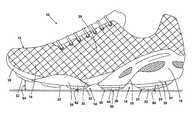
- FIG. 1is a side elevational view of an embodiment of a shoe according to the invention.
- FIG. 2is a view from the underside of the shoe illustrated in FIG. 1 .
- FIG. 3is a side elevational view of the shoe illustrated in FIG. 1 showing the degree of rocker associated with the shoe.
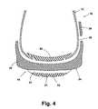
- FIG. 4is a schematic sectional view taken along view line 4 - 4 of FIG. 1 .
- FIG. 5is a perspective view of a stability shell forming part of the shoe illustrated in FIG. 1 .
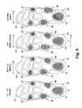
- FIG. 6Ais a plan view from the underside of the shoe illustrated in FIG. 1 providing a neutral degree of correction.
- FIG. 6Bis a view is similar to FIG. 6A of a shoe providing correction for a slight degree of late pronation.
- FIG. 6Cis a view similar to FIG. 6A of a shoe providing correction for an extensive degree of pronation.
- FIG. 6Dis a view similar to FIG. 6A of a shoe providing correction for supination.
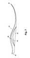
- FIG. 7is a side elevational view of an arch adjustment support for utilization in the shoe illustrated in FIG. 1 showing 3 progressively effective configurations.
- FIG. 1an embodiment of the invention is illustrated comprising a shoe 10 having a generally known upper portion 12 .
- the shoe 10has a forefoot portion 16 , such as a toe box, a midfoot portion 26 associated with a wearer's arch, and a heel portion 18 , such as a heel cradle.
- the shoe 10is illustrated as an athletic, lace-up style. However, the shoe 10 can be of any selected style.
- the shoe 10has a sole 14 comprising a platform 20 .
- the forefoot portion of the sole 14comprises an array of forefoot support pads 32 integrated therein and extending away from the platform 20 for cushioning the forefoot, and providing fraction and lateral stability.
- FIG. 2illustrates an exemplary distribution and configuration of the support pads 32 .
- the configuration and distribution of the support pads 32can be selected based upon factors such as shoe flexibility, weight distribution in the forefoot portion, degree of cushioning, and the like.
- the heel portion of the sole 14comprises a heel pedestal 21 extending away from the platform 20 and centered generally beneath the heel bone.
- the heel pedestal 21is illustrated as somewhat egg-shaped in plan view, although the heel pedestal 21 can be configured with other shapes, such as circular, triangular, oval, and the like.
- Extending generally arcuately along the perimeter of the heel portion 18 from the medial area to the lateral area of the heel portion 18is a heel stabilizer 24 extending away from the platform 20 .
- the heel pedestal 21extends below the heel stabilizer 24 as illustrated in FIG. 1 .
- a medial stabilizer pedestal 28 and a lateral stabilizer pedestal 30are positioned foreword of the heel stabilizer 24 .
- the medial stabilizer pedestal 28is positioned beneath the navicular bone (not shown) in order to provide support and control for the joints associated with the navicular.
- the lateral stabilizer pedestal 30is positioned below the cuboid bone (not shown) in order to provide support and control for the joints associated with the cuboid.
- the medial stabilizer pedestal 28is generally positioned somewhat forward of the lateral stabilizer pedestal 30 .
- both pedestals 28 , 30are positioned to extend laterally beyond the perimeter of the sole 14 . This provides an enhanced degree of lateral stability compared to a conventional sole.
- a rigid bridge 36couples the heel pedestal 21 with the medial stabilizer pedestal 28 and the lateral stabilizer pedestal 30 to provide an integral, 3-point support structure.
- the shoe 10is also configured to provide a selected degree of longitudinal forefoot rocker and heel rocker when the shoe is resting unworn on a horizontal surface.
- Rockeris defined in terms of the distance of selected reference points above a supporting surface with only the medial stabilizer pedestal 28 and the lateral stabilizer pedestal 30 in contact with the supporting surface.
- the intermediate height of the center of the adjacent forefoot support pad 32will be between 2 and 4 millimeters.
- the forward height 84 of the center of the most distal forefoot support pad 32will be between 2 and 3 centimeters, and the heel height 86 of the center of the heel pedestal 21 will be between 3 and 5 millimeters.
- the shoe 10is supported on the heel pedestal 21 , the medial stabilizer pedestal 28 , and the lateral stabilizer pedestal 30 .
- Thisprovides a 3-point support base for the user's foot which is highly stable and resistant to foot roll. While a wearer's weight may compress the pedestals 21 , 28 , 30 so that the forefoot portion 16 contacts the supporting surface, the pedestals 21 , 28 , 30 will play a significant role in supporting and controlling the wearer's weight during standing and bipedal locomotion.
- the forefoot rockeris defined in part by a stability shell 40 as illustrated in FIG. 5 .
- the stability shell 40is a thin, semi-rigid, generally foot-shaped body having a plantar portion 72 and a heel cup 74 .
- the plantar portion 72can be flat, or can optionally have a somewhat longitudinally upwardly-curved profile. Any curvature of the plantar portion 72 may be adapted to be complementary to the longitudinal forefoot rocker of the shoe 10 .
- the stability shell 40can be integrated into the shoe 10 between the insole and the outsole. In addition to contributing to a selected degree of forefoot rocker, the stability shell 40 controls foot roll or twisting during bipedal locomotion. This control is provided because the stability shell 40 extends beneath the wearer's entire foot, encompassing the heel and extending to the ends of the toes.
- FIG. 4is a somewhat schematic sectional view through the heel portion of the shoe 10 illustrating a construction of the shoe 10 .
- the heel pedestal 21comprises a heel outsole 22 , a highly compressible middle layer 25 , and a relatively moderately compressible base layer 39 .
- the heel outsole 22comprises a tough, wear-resistant material, such as a rubber or other materials commonly used for shoe soles.
- the heel outsole 22overlies the middle layer 25 , which is fabricated of a compressible material, such as ethylene vinyl acetate (EVA).
- EVAethylene vinyl acetate
- the middle layer 25extends from the base layer 39 , which is also fabricated of an EVA, but with a higher density and lower compressibility than the middle layer 25 .
- To the inside of the base layer 39is the stability shell 40 .
- the stability shell 40can be fabricated of a tough, moderately flexible material, such as a thermoplastic polyurethane (TPU).
- TPUthermoplastic polyurethane
- the stability shell 40can be configured with a cut-out adapted to receive a cushioning pad fabricated of a suitable cushioning material, such as EVA having a selected density and compressibility, to provide additional cushioning to the heel.
- the base layer 39can also be extended along the sides of the shoe 10 in a selected configuration to provide abrasion resistance and enhanced support, particularly the of heel.
- the medial stabilizer pedestal 28 and the lateral stabilizer pedestal 30are similarly fabricated with a stabilizer pedestal outsole 46 , 44 , respectively, and a compressible middle layer 38 interposed between the outsole 44 , 46 and the base layer 39 .
- the heelIn use, as a person takes a step, the heel is the first part of the foot to make contact with the walking or running surface.
- the rear portion of the heel stabilizer 24will be brought into initial contact with the surface, and will compress moderately due to the moderately compressible properties of the heel stabilizer EVA.
- the compressibility of the heel stabilizer EVAwill also contribute to lateral stability of the foot while the heel is supporting much of the wearer's weight. This lateral stability will facilitate a selected transfer of weight from the heel through the midfoot to the forefoot.
- the heel pedestal 21will contact the surface, and at least a portion of the wearer's weight will be transferred from the heel stabilizer 24 to the heel pedestal 21 .
- the highly compressible midlayer 25will compress, along with the less compressible base layer 39 .
- the portions of the heel stabilizer 24 along the lateral and medial areas of the heel portion 18will continue to carry some portion of the wearer's weight to provide lateral stability.
- the heel pedestal 21will tend to maintain the selected lateral positioning of the heel to align the weight properly with respect to the heel bone.
- the heel cup 74will also contribute to the selected positioning of the wearer's heel relative to the heel pedestal 21 .
- the wearer's weightwill be transferred, first to the lateral stabilizer pedestal 30 , then to the medial stabilizer pedestal 28 .
- the pedestal 30will compress somewhat, but will control undesirable supination.
- the relative positioning of the heel pedestal 21 and the lateral stabilizer pedestal 30will control the early transfer of weight from the heel to the midfoot.
- FIG. 2illustrates one configuration and positioning of the stabilizer pedestals 28 , 30 .
- the anticipated use of the shoee.g. athletics, casual wear, etc., may dictate variations in size, configuration, and placement of the stabilizer pedestals 28 , 30 beyond that illustrated in FIG. 2 .
- the wearer's weightwill be supported entirely on the 3-point support base consisting of the heel pedestal 21 the medial stabilizer pedestal 28 , and the lateral stabilizer pedestal 30 . This will properly orient the wearer's foot for transfer of the wearer's weight to the forefoot, thereby maintaining a selected gait without excessive pronation or supination.
- the forefoot support pads 32will provide selected support to the individual bones in the plantar region of the foot, further controlling pronation or supination and facilitating maintenance of a selected gait.
- FIGS. 6A-Dillustrate 4 general conditions relating to foot orientation and gait in the context of the shoe described herein.
- the Figuresillustrate 4 plan views of the sole of the shoe 10 for addressing the 4 conditions.
- Each conditionis defined by the results of a calcaneal eversion measurement, such as taken with a subtalar joint goniometer (not shown) as described in Applicant's U.S. Pat. No. 7,069,665.
- FIG. 6Arelates to a calcaneal eversion measurement of 6-10°
- FIG. 6Brelates to a calcaneal eversion measurement of 10-13°
- FIG. 6Crelates to a calcaneal eversion measurement of 14° or greater
- 6Drelates to a calcaneal eversion measurement of 5° or less. These are also referred to, respectively, as “neutral,” “stability,” “motion control,” and “cavus.” After determining whether a patient's foot presents as “neutral,” “stability,” “motion control,” or “cavus,” the shoe 10 can be further adjusted to accommodate each condition.
- the shoecan be adjusted by raising the medial edge of the forefoot portion approximately 2° by a wedge or similar structure extending along the medial region of the forefoot portion from the forward end of the shoe to just forward of the medial stabilizer pedestal 28 .
- the lateral edgeis not raised. This will provide a lateral inclination of the forefoot portion ranging from zero to 2° across the forefoot portion toward the medial edge.
- the shoeis adjusted by raising the medial edge of the forefoot portion approximately 2°, and the medial edge of the heel portion approximately 1°, by one or more wedges or similar structures.
- a single wedgecan extend along the medial portion of the sole from the forefoot portion 16 to the heel portion 18 to provide a selected adjustment.
- the lateral edgesare not raised.
- the wedgewill provide a lateral inclination of the forefoot portion ranging from zero to 2° toward the medial edge, and a lateral inclination of the heel portion ranging from zero to 1° across the heel portion toward the medial edge.
- the medial stabilizer pedestal 28 ′can be appropriately enlarged.
- the shoecan be adjusted by raising the lateral edge of the forefoot portion approximately 2° by a wedge or similar structure extending along the lateral region of the forefoot portion from the forward end of the shoe to just forward of the lateral stabilizer pedestal 30 . Additionally, the lateral stabilizer pedestal 30 ′ can be appropriately enlarged. The medial edge of the forefoot portion is not raised. Adjustments to address the “cavus” condition will tend to control supination.
- the wedgewill provide a lateral inclination of the forefoot portion ranging from zero to 2° toward the lateral edge.
- the shoe 10can also be fitted with an arch support insert 56 comprising a forward end 58 extending to the ends of the toes, and a heel end 60 beneath the heel.
- the insert 56can be provided with a low arch profile 62 , a medium arch profile 64 , or a high arch profile 66 , based upon a selected arch profile appropriate for the person to whom the shoe 10 is being fitted.
- the stability shell 40can be modified to include a selected arch profile. The insert 56 or stability shell 40 can thereby provide further support to the foot and control of the wearer's gait.
Landscapes
- Health & Medical Sciences (AREA)
- Epidemiology (AREA)
- General Health & Medical Sciences (AREA)
- Public Health (AREA)
- Chemical & Material Sciences (AREA)
- Engineering & Computer Science (AREA)
- Materials Engineering (AREA)
- Footwear And Its Accessory, Manufacturing Method And Apparatuses (AREA)
Abstract
Description
Claims (10)
Priority Applications (2)
| Application Number | Priority Date | Filing Date | Title |
|---|---|---|---|
| US12/041,958US8079159B1 (en) | 2007-03-06 | 2008-03-04 | Footwear |
| US13/330,845US8938889B2 (en) | 2007-03-06 | 2011-12-20 | Footwear |
Applications Claiming Priority (2)
| Application Number | Priority Date | Filing Date | Title |
|---|---|---|---|
| US89327307P | 2007-03-06 | 2007-03-06 | |
| US12/041,958US8079159B1 (en) | 2007-03-06 | 2008-03-04 | Footwear |
Related Child Applications (1)
| Application Number | Title | Priority Date | Filing Date |
|---|---|---|---|
| US13/330,845Continuation-In-PartUS8938889B2 (en) | 2007-03-06 | 2011-12-20 | Footwear |
Publications (1)
| Publication Number | Publication Date |
|---|---|
| US8079159B1true US8079159B1 (en) | 2011-12-20 |
Family
ID=45219116
Family Applications (1)
| Application Number | Title | Priority Date | Filing Date |
|---|---|---|---|
| US12/041,958Expired - Fee RelatedUS8079159B1 (en) | 2007-03-06 | 2008-03-04 | Footwear |
Country Status (1)
| Country | Link |
|---|---|
| US (1) | US8079159B1 (en) |
Cited By (44)
| Publication number | Priority date | Publication date | Assignee | Title |
|---|---|---|---|---|
| US20100325919A1 (en)* | 2002-08-19 | 2010-12-30 | Avi Elbaz | Proprioceptive/kinesthetic apparatus and method |
| US20120137544A1 (en)* | 2007-03-06 | 2012-06-07 | Adriano Rosa | Footwear |
| USD677869S1 (en) | 2011-12-20 | 2013-03-19 | Deckers Outdoor Corporation | Footwear sole |
| US8463657B1 (en)* | 2010-04-01 | 2013-06-11 | Joe Bentvelzen | Self-help system and method for selling footwear |
| USD707431S1 (en)* | 2012-06-11 | 2014-06-24 | Taylor Made Golf Company, Inc. | Golf shoe outsole |
| WO2014056687A3 (en)* | 2012-10-09 | 2014-07-17 | Bs Sweedspeed Ab | Sole structure for biomechanical control |
| US9357812B2 (en) | 2002-08-19 | 2016-06-07 | APOS—Medical and Sports Technologies Ltd. | Proprioceptive/kinesthetic apparatus and method |
| US20170208898A1 (en)* | 2015-09-23 | 2017-07-27 | Hyman Kramer | Footwear devices |
| USD801015S1 (en)* | 2016-11-12 | 2017-10-31 | Nike, Inc. | Shoe outsole |
| WO2018014132A1 (en)* | 2016-07-20 | 2018-01-25 | Rudan Michael | Material for enhancing the effects of exercise |
| AT519205A1 (en)* | 2016-09-23 | 2018-04-15 | Robert Schloegl | sole |
| USD817618S1 (en)* | 2016-11-16 | 2018-05-15 | Nike, Inc. | Shoe sole |
| US10004614B1 (en) | 2016-11-02 | 2018-06-26 | Joe Johnson | Disarticulated compression socket |
| US20180368509A1 (en)* | 2017-06-26 | 2018-12-27 | Nike, Inc. | Article of footwear with a pronation feedback system |
| USD850769S1 (en)* | 2018-02-12 | 2019-06-11 | Nike, Inc. | Shoe |
| FR3074651A1 (en)* | 2017-12-13 | 2019-06-14 | Jet Green | SPORT SHOE HAVING A HULL INTERPOSED BETWEEN THE ROD AND A SOLE OF COMFORT |
| US10327504B2 (en) | 2015-04-24 | 2019-06-25 | Nike, Inc. | Footwear sole structure having bladder with integrated outsole |
| USD854294S1 (en)* | 2018-03-01 | 2019-07-23 | Nike, Inc. | Shoe |
| IT201800002726A1 (en)* | 2018-02-15 | 2019-08-15 | Health And Fashion Shoes Italia S P A | Sole structure for footwear. |
| USD871732S1 (en)* | 2019-02-22 | 2020-01-07 | Nike, Inc. | Shoe |
| FR3087096A1 (en) | 2018-10-15 | 2020-04-17 | Jet Green | FOOTWEAR FOR THE PRACTICE OF PHYSICAL ACTIVITIES |
| US10736379B2 (en) | 2017-06-02 | 2020-08-11 | Nike, Inc. | Article of footwear with internal feedback elements |
| US10744368B2 (en) | 2010-07-02 | 2020-08-18 | Apos Medical And Sports Technologies Ltd. | Device and methods for tuning a skeletal muscle |
| USD907344S1 (en) | 2017-09-14 | 2021-01-12 | Puma SE | Shoe |
| USD910290S1 (en) | 2017-09-14 | 2021-02-16 | Puma SE | Shoe |
| USD911683S1 (en) | 2017-09-14 | 2021-03-02 | Puma SE | Shoe |
| USD911682S1 (en) | 2017-09-14 | 2021-03-02 | Puma SE | Shoe |
| US20210267306A1 (en)* | 2018-12-28 | 2021-09-02 | Asics Corporation | Shoe sole and shoe |
| US11134748B2 (en) | 2018-10-15 | 2021-10-05 | The North Face Apparel Corp. | Footwear with a shell |
| US20220015499A1 (en)* | 2020-07-14 | 2022-01-20 | Asics Corporation | Shoe sole and shoe |
| USD944504S1 (en) | 2020-04-27 | 2022-03-01 | Puma SE | Shoe |
| US11291273B2 (en) | 2017-08-11 | 2022-04-05 | Puma SE | Method for producing a shoe |
| USD953709S1 (en) | 1985-08-29 | 2022-06-07 | Puma SE | Shoe |
| USD960541S1 (en) | 2017-01-17 | 2022-08-16 | Puma SE | Shoe |
| US11503875B2 (en)* | 2019-07-19 | 2022-11-22 | Nike, Inc. | Sole structures including polyolefin plates and articles of footwear formed therefrom |
| USD975417S1 (en) | 2017-09-14 | 2023-01-17 | Puma SE | Shoe |
| US11638461B2 (en)* | 2019-04-10 | 2023-05-02 | Salomon S.A.S. | Sports shoe |
| US11678718B2 (en) | 2018-01-24 | 2023-06-20 | Nike, Inc. | Sole structures including polyolefin plates and articles of footwear formed therefrom |
| US11696620B2 (en) | 2019-07-19 | 2023-07-11 | Nike, Inc. | Articles of footwear including sole structures and rand |
| US11832684B2 (en) | 2018-04-27 | 2023-12-05 | Puma SE | Shoe, in particular a sports shoe |
| US11844667B2 (en) | 2016-11-02 | 2023-12-19 | Joe Johnson | Disarticulated compression socket |
| US12022909B2 (en) | 2021-08-30 | 2024-07-02 | Nike, Inc. | Polyolefin-based resins, sole structures, and articles of footwear and sporting equipment formed therefrom |
| US12042001B2 (en) | 2018-12-18 | 2024-07-23 | Puma SE | Shoe, in particular sports shoe, and method for producing same |
| JP7708468B1 (en)* | 2024-06-19 | 2025-07-15 | 株式会社M.Lab | Sole attachment |
Citations (11)
| Publication number | Priority date | Publication date | Assignee | Title |
|---|---|---|---|---|
| US6119373A (en)* | 1996-08-20 | 2000-09-19 | Adidas International B.V. | Shoe having an external chassis |
| US6237251B1 (en)* | 1991-08-21 | 2001-05-29 | Reebok International Ltd. | Athletic shoe construction |
| US6516540B2 (en)* | 1994-10-21 | 2003-02-11 | Adidas Ag | Ground contacting systems having 3D deformation elements for use in footwear |
| US6591519B1 (en)* | 1989-08-30 | 2003-07-15 | Anatomic Research, Inc. | Shoe sole structures |
| US6658766B2 (en)* | 1996-08-20 | 2003-12-09 | Adidas A.G. | Shoe having an internal chassis |
| US6662470B2 (en)* | 1989-08-30 | 2003-12-16 | Anatomic Research, Inc. | Shoes sole structures |
| US20050210705A1 (en)* | 2003-01-21 | 2005-09-29 | Nike, Inc. | Footwear with separable upper and sole structure |
| US20050217142A1 (en)* | 1999-04-26 | 2005-10-06 | Ellis Frampton E Iii | Shoe sole orthotic structures and computer controlled compartments |
| US7069665B1 (en) | 2002-07-19 | 2006-07-04 | Biocorrect L.L.C. | Correcting foot alignment |
| US20070240331A1 (en)* | 2006-04-14 | 2007-10-18 | Salomon S.A. | Shock-absorbing system for an article of footwear |
| US20080052965A1 (en)* | 2006-08-30 | 2008-03-06 | Mizuno Corporation | Midfoot structure of a sole assembly for a shoe |
- 2008
- 2008-03-04USUS12/041,958patent/US8079159B1/ennot_activeExpired - Fee Related
Patent Citations (13)
| Publication number | Priority date | Publication date | Assignee | Title |
|---|---|---|---|---|
| US6591519B1 (en)* | 1989-08-30 | 2003-07-15 | Anatomic Research, Inc. | Shoe sole structures |
| US6662470B2 (en)* | 1989-08-30 | 2003-12-16 | Anatomic Research, Inc. | Shoes sole structures |
| US6237251B1 (en)* | 1991-08-21 | 2001-05-29 | Reebok International Ltd. | Athletic shoe construction |
| US6516540B2 (en)* | 1994-10-21 | 2003-02-11 | Adidas Ag | Ground contacting systems having 3D deformation elements for use in footwear |
| US6119373A (en)* | 1996-08-20 | 2000-09-19 | Adidas International B.V. | Shoe having an external chassis |
| US6658766B2 (en)* | 1996-08-20 | 2003-12-09 | Adidas A.G. | Shoe having an internal chassis |
| US6438873B1 (en)* | 1996-08-20 | 2002-08-27 | Adidas International B.V. | Shoe having an external chassis |
| US20050217142A1 (en)* | 1999-04-26 | 2005-10-06 | Ellis Frampton E Iii | Shoe sole orthotic structures and computer controlled compartments |
| US7069665B1 (en) | 2002-07-19 | 2006-07-04 | Biocorrect L.L.C. | Correcting foot alignment |
| US20050210705A1 (en)* | 2003-01-21 | 2005-09-29 | Nike, Inc. | Footwear with separable upper and sole structure |
| US20060213088A1 (en)* | 2003-01-21 | 2006-09-28 | Nike, Inc. | Footwear with separable upper and sole structure |
| US20070240331A1 (en)* | 2006-04-14 | 2007-10-18 | Salomon S.A. | Shock-absorbing system for an article of footwear |
| US20080052965A1 (en)* | 2006-08-30 | 2008-03-06 | Mizuno Corporation | Midfoot structure of a sole assembly for a shoe |
Cited By (65)
| Publication number | Priority date | Publication date | Assignee | Title |
|---|---|---|---|---|
| USD953709S1 (en) | 1985-08-29 | 2022-06-07 | Puma SE | Shoe |
| US9788597B2 (en) | 2002-08-19 | 2017-10-17 | APOS—Medical and Sports Technologies Ltd. | Proprioceptive/kinesthetic apparatus and method |
| US8758207B2 (en)* | 2002-08-19 | 2014-06-24 | APOS—Medical and Sports Technologies Ltd. | Proprioceptive/kinesthetic apparatus and method |
| US9055788B2 (en) | 2002-08-19 | 2015-06-16 | APOS—Medical and Sports Technologies Ltd. | Proprioceptive/kinesthetic apparatus and method |
| US20100325919A1 (en)* | 2002-08-19 | 2010-12-30 | Avi Elbaz | Proprioceptive/kinesthetic apparatus and method |
| US9357812B2 (en) | 2002-08-19 | 2016-06-07 | APOS—Medical and Sports Technologies Ltd. | Proprioceptive/kinesthetic apparatus and method |
| US20120137544A1 (en)* | 2007-03-06 | 2012-06-07 | Adriano Rosa | Footwear |
| US8938889B2 (en)* | 2007-03-06 | 2015-01-27 | Deckers Outdoor Corporation | Footwear |
| US8463657B1 (en)* | 2010-04-01 | 2013-06-11 | Joe Bentvelzen | Self-help system and method for selling footwear |
| US10744368B2 (en) | 2010-07-02 | 2020-08-18 | Apos Medical And Sports Technologies Ltd. | Device and methods for tuning a skeletal muscle |
| USD677869S1 (en) | 2011-12-20 | 2013-03-19 | Deckers Outdoor Corporation | Footwear sole |
| USD707431S1 (en)* | 2012-06-11 | 2014-06-24 | Taylor Made Golf Company, Inc. | Golf shoe outsole |
| WO2014056687A3 (en)* | 2012-10-09 | 2014-07-17 | Bs Sweedspeed Ab | Sole structure for biomechanical control |
| US20150264998A1 (en)* | 2012-10-09 | 2015-09-24 | Bs Sweedspeed Ab | Sole structure for biomechanical control |
| US10327504B2 (en) | 2015-04-24 | 2019-06-25 | Nike, Inc. | Footwear sole structure having bladder with integrated outsole |
| US20170208898A1 (en)* | 2015-09-23 | 2017-07-27 | Hyman Kramer | Footwear devices |
| WO2018014132A1 (en)* | 2016-07-20 | 2018-01-25 | Rudan Michael | Material for enhancing the effects of exercise |
| AT16641U1 (en)* | 2016-09-23 | 2020-03-15 | Robert Schloegl | Shoe sole |
| AT519205A1 (en)* | 2016-09-23 | 2018-04-15 | Robert Schloegl | sole |
| US10004614B1 (en) | 2016-11-02 | 2018-06-26 | Joe Johnson | Disarticulated compression socket |
| US11844667B2 (en) | 2016-11-02 | 2023-12-19 | Joe Johnson | Disarticulated compression socket |
| US10406003B2 (en) | 2016-11-02 | 2019-09-10 | Joe Johnson | Disarticulated compression socket |
| USD801015S1 (en)* | 2016-11-12 | 2017-10-31 | Nike, Inc. | Shoe outsole |
| USD817618S1 (en)* | 2016-11-16 | 2018-05-15 | Nike, Inc. | Shoe sole |
| USD1054656S1 (en) | 2017-01-17 | 2024-12-24 | Puma SE | Shoe |
| USD960541S1 (en) | 2017-01-17 | 2022-08-16 | Puma SE | Shoe |
| US10736379B2 (en) | 2017-06-02 | 2020-08-11 | Nike, Inc. | Article of footwear with internal feedback elements |
| US20180368509A1 (en)* | 2017-06-26 | 2018-12-27 | Nike, Inc. | Article of footwear with a pronation feedback system |
| US11291273B2 (en) | 2017-08-11 | 2022-04-05 | Puma SE | Method for producing a shoe |
| USD907344S1 (en) | 2017-09-14 | 2021-01-12 | Puma SE | Shoe |
| USD911682S1 (en) | 2017-09-14 | 2021-03-02 | Puma SE | Shoe |
| USD953710S1 (en) | 2017-09-14 | 2022-06-07 | Puma SE | Shoe |
| USD975417S1 (en) | 2017-09-14 | 2023-01-17 | Puma SE | Shoe |
| USD909723S1 (en) | 2017-09-14 | 2021-02-09 | Puma SE | Shoe |
| USD910290S1 (en) | 2017-09-14 | 2021-02-16 | Puma SE | Shoe |
| USD911683S1 (en) | 2017-09-14 | 2021-03-02 | Puma SE | Shoe |
| USD922042S1 (en) | 2017-09-14 | 2021-06-15 | Puma SE | Shoe |
| USD921342S1 (en) | 2017-09-14 | 2021-06-08 | Puma SE | Shoe |
| FR3074651A1 (en)* | 2017-12-13 | 2019-06-14 | Jet Green | SPORT SHOE HAVING A HULL INTERPOSED BETWEEN THE ROD AND A SOLE OF COMFORT |
| US11930881B2 (en) | 2018-01-24 | 2024-03-19 | Nike, Inc. | Sole structures including polyolefin plates and articles of footwear formed therefrom |
| US11678718B2 (en) | 2018-01-24 | 2023-06-20 | Nike, Inc. | Sole structures including polyolefin plates and articles of footwear formed therefrom |
| US12290132B2 (en) | 2018-01-24 | 2025-05-06 | Nike, Inc. | Sole structures including polyolefin plates and articles of footwear formed therefrom |
| USD850769S1 (en)* | 2018-02-12 | 2019-06-11 | Nike, Inc. | Shoe |
| IT201800002726A1 (en)* | 2018-02-15 | 2019-08-15 | Health And Fashion Shoes Italia S P A | Sole structure for footwear. |
| USD854294S1 (en)* | 2018-03-01 | 2019-07-23 | Nike, Inc. | Shoe |
| US11832684B2 (en) | 2018-04-27 | 2023-12-05 | Puma SE | Shoe, in particular a sports shoe |
| WO2020081560A1 (en) | 2018-10-15 | 2020-04-23 | The North Face Apparel Corp. | Shoe designed to enhance the practice of physical activities |
| FR3087096A1 (en) | 2018-10-15 | 2020-04-17 | Jet Green | FOOTWEAR FOR THE PRACTICE OF PHYSICAL ACTIVITIES |
| US11700910B2 (en) | 2018-10-15 | 2023-07-18 | The North Face Apparel Corp. | Footwear with a shell |
| WO2020081566A1 (en) | 2018-10-15 | 2020-04-23 | The North Face Apparel Corp. | Footwear with a shell |
| US11134748B2 (en) | 2018-10-15 | 2021-10-05 | The North Face Apparel Corp. | Footwear with a shell |
| US12042001B2 (en) | 2018-12-18 | 2024-07-23 | Puma SE | Shoe, in particular sports shoe, and method for producing same |
| US11825903B2 (en)* | 2018-12-28 | 2023-11-28 | Asics Corporation | Shoe sole and shoe |
| US20210267306A1 (en)* | 2018-12-28 | 2021-09-02 | Asics Corporation | Shoe sole and shoe |
| USD871732S1 (en)* | 2019-02-22 | 2020-01-07 | Nike, Inc. | Shoe |
| US11638461B2 (en)* | 2019-04-10 | 2023-05-02 | Salomon S.A.S. | Sports shoe |
| US11503875B2 (en)* | 2019-07-19 | 2022-11-22 | Nike, Inc. | Sole structures including polyolefin plates and articles of footwear formed therefrom |
| US11696620B2 (en) | 2019-07-19 | 2023-07-11 | Nike, Inc. | Articles of footwear including sole structures and rand |
| US11944152B2 (en) | 2019-07-19 | 2024-04-02 | Nike, Inc. | Sole structures including polyolefin plates and articles of footwear formed therefrom |
| USD1040491S1 (en) | 2020-04-27 | 2024-09-03 | Puma SE | Shoe |
| USD944504S1 (en) | 2020-04-27 | 2022-03-01 | Puma SE | Shoe |
| US20220015499A1 (en)* | 2020-07-14 | 2022-01-20 | Asics Corporation | Shoe sole and shoe |
| US12383026B2 (en)* | 2020-07-14 | 2025-08-12 | Asics Corporation | Shoe sole and shoe |
| US12022909B2 (en) | 2021-08-30 | 2024-07-02 | Nike, Inc. | Polyolefin-based resins, sole structures, and articles of footwear and sporting equipment formed therefrom |
| JP7708468B1 (en)* | 2024-06-19 | 2025-07-15 | 株式会社M.Lab | Sole attachment |
Similar Documents
| Publication | Publication Date | Title |
|---|---|---|
| US8079159B1 (en) | Footwear | |
| US8938889B2 (en) | Footwear | |
| US10702008B2 (en) | Device and method of constructing shoes | |
| US8387278B2 (en) | Sole for footwear | |
| US4620376A (en) | Forefoot valgus compensated footwear | |
| US8756836B2 (en) | Foot support | |
| US4453322A (en) | Sandal having side wall for preventing pronation | |
| US20130291398A1 (en) | Footwear insole for high heel shoes | |
| US20100269371A1 (en) | Orthotic shoe insert for high-heeled shoes | |
| US5327663A (en) | Supination control sole and shoe | |
| US4272899A (en) | Footwear | |
| US20110314699A1 (en) | Footwear With Rocker Sole | |
| JP2023505321A (en) | Shoes with a sole that achieves dynamic plantar arch support | |
| JPH09140405A (en) | Hallux valgus footwear and insoles | |
| US20140338220A1 (en) | Footwear/insole for footwear | |
| US7360326B1 (en) | Flexible footwear sole | |
| KR20100121692A (en) | Device for high-heeled shoes and method of constructing a high-heeled shoe | |
| CN114765944A (en) | Shoe with dynamic heel support sole | |
| US20110289802A1 (en) | Shoe appliance with an orthopedic device | |
| US20240381974A1 (en) | Sole contact body | |
| JP2014233563A (en) | Sole pad | |
| US20250176660A1 (en) | Padded shoe for body balance adjustment by body type | |
| US11540588B1 (en) | Footwear insole | |
| KR102311104B1 (en) | Footwear midsole and insole for rheumatism gout | |
| US20220312892A1 (en) | Footwear sole with a midfoot lateral extension to increase lateral stability |
Legal Events
| Date | Code | Title | Description |
|---|---|---|---|
| ZAAA | Notice of allowance and fees due | Free format text:ORIGINAL CODE: NOA | |
| ZAAB | Notice of allowance mailed | Free format text:ORIGINAL CODE: MN/=. | |
| STCF | Information on status: patent grant | Free format text:PATENTED CASE | |
| REMI | Maintenance fee reminder mailed | ||
| FPAY | Fee payment | Year of fee payment:4 | |
| SULP | Surcharge for late payment | ||
| FEPP | Fee payment procedure | Free format text:ENTITY STATUS SET TO SMALL (ORIGINAL EVENT CODE: SMAL); ENTITY STATUS OF PATENT OWNER: SMALL ENTITY | |
| FEPP | Fee payment procedure | Free format text:MAINTENANCE FEE REMINDER MAILED (ORIGINAL EVENT CODE: REM.); ENTITY STATUS OF PATENT OWNER: SMALL ENTITY | |
| FEPP | Fee payment procedure | Free format text:7.5 YR SURCHARGE - LATE PMT W/IN 6 MO, SMALL ENTITY (ORIGINAL EVENT CODE: M2555); ENTITY STATUS OF PATENT OWNER: SMALL ENTITY | |
| MAFP | Maintenance fee payment | Free format text:PAYMENT OF MAINTENANCE FEE, 8TH YR, SMALL ENTITY (ORIGINAL EVENT CODE: M2552); ENTITY STATUS OF PATENT OWNER: SMALL ENTITY Year of fee payment:8 | |
| FEPP | Fee payment procedure | Free format text:MAINTENANCE FEE REMINDER MAILED (ORIGINAL EVENT CODE: REM.); ENTITY STATUS OF PATENT OWNER: SMALL ENTITY | |
| LAPS | Lapse for failure to pay maintenance fees | Free format text:PATENT EXPIRED FOR FAILURE TO PAY MAINTENANCE FEES (ORIGINAL EVENT CODE: EXP.); ENTITY STATUS OF PATENT OWNER: SMALL ENTITY | |
| STCH | Information on status: patent discontinuation | Free format text:PATENT EXPIRED DUE TO NONPAYMENT OF MAINTENANCE FEES UNDER 37 CFR 1.362 | |
| FP | Lapsed due to failure to pay maintenance fee | Effective date:20231220 |