US8078274B2 - Device, system and method for measuring cross-sectional areas in luminal organs - Google Patents
Device, system and method for measuring cross-sectional areas in luminal organsDownload PDFInfo
- Publication number
- US8078274B2 US8078274B2US12/098,242US9824208AUS8078274B2US 8078274 B2US8078274 B2US 8078274B2US 9824208 AUS9824208 AUS 9824208AUS 8078274 B2US8078274 B2US 8078274B2
- Authority
- US
- United States
- Prior art keywords
- treatment site
- conductance
- cross
- solution
- conductivity
- Prior art date
- Legal status (The legal status is an assumption and is not a legal conclusion. Google has not performed a legal analysis and makes no representation as to the accuracy of the status listed.)
- Active, expires
Links
- 238000000034methodMethods0.000titleclaimsabstractdescription196
- 210000000056organAnatomy0.000titleabstractdescription50
- 238000011282treatmentMethods0.000claimsabstractdescription289
- 238000005259measurementMethods0.000claimsabstractdescription86
- 239000000243solutionSubstances0.000claimsdescription123
- FAPWRFPIFSIZLT-UHFFFAOYSA-MSodium chlorideChemical compound[Na+].[Cl-]FAPWRFPIFSIZLT-UHFFFAOYSA-M0.000claimsdescription93
- 238000002347injectionMethods0.000claimsdescription84
- 239000007924injectionSubstances0.000claimsdescription84
- 239000012530fluidSubstances0.000claimsdescription49
- 239000011780sodium chlorideSubstances0.000claimsdescription47
- 238000001514detection methodMethods0.000claimsdescription45
- 208000031481Pathologic ConstrictionDiseases0.000claimsdescription29
- 210000004369bloodAnatomy0.000claimsdescription27
- 239000008280bloodSubstances0.000claimsdescription27
- 230000005284excitationEffects0.000claimsdescription27
- 208000037804stenosisDiseases0.000claimsdescription27
- 230000036262stenosisEffects0.000claimsdescription26
- 238000004458analytical methodMethods0.000claimsdescription21
- 238000001802infusionMethods0.000claimsdescription20
- 239000000463materialSubstances0.000claimsdescription12
- 238000004364calculation methodMethods0.000claimsdescription11
- 210000003238esophagusAnatomy0.000claimsdescription8
- 238000012545processingMethods0.000claimsdescription8
- 230000005684electric fieldEffects0.000claimsdescription7
- 230000036760body temperatureEffects0.000claimsdescription5
- 210000003445biliary tractAnatomy0.000claimsdescription3
- 238000004891communicationMethods0.000claimsdescription2
- 210000004204blood vesselAnatomy0.000abstractdescription4
- 210000003709heart valveAnatomy0.000abstractdescription3
- 230000009278visceral effectEffects0.000abstractdescription3
- 238000013459approachMethods0.000description42
- 206010002906aortic stenosisDiseases0.000description28
- 230000000747cardiac effectEffects0.000description14
- 210000001519tissueAnatomy0.000description14
- 238000002604ultrasonographyMethods0.000description13
- 210000004351coronary vesselAnatomy0.000description12
- 210000001765aortic valveAnatomy0.000description10
- 238000002608intravascular ultrasoundMethods0.000description8
- 238000002399angioplastyMethods0.000description7
- 238000004422calculation algorithmMethods0.000description7
- 210000001715carotid arteryAnatomy0.000description7
- 208000024891symptomDiseases0.000description7
- 210000001105femoral arteryAnatomy0.000description6
- 208000009378Low Cardiac OutputDiseases0.000description5
- 230000008859changeEffects0.000description5
- 238000001727in vivoMethods0.000description5
- 238000010200validation analysisMethods0.000description5
- 206010002383Angina PectorisDiseases0.000description4
- 208000029078coronary artery diseaseDiseases0.000description4
- 238000012937correctionMethods0.000description4
- 230000006870functionEffects0.000description4
- 230000008569processEffects0.000description4
- 239000000523sampleSubstances0.000description4
- 210000000626ureterAnatomy0.000description4
- 210000001835visceraAnatomy0.000description4
- 241000282898Sus scrofaSpecies0.000description3
- 238000002583angiographyMethods0.000description3
- 210000001367arteryAnatomy0.000description3
- 210000001124body fluidAnatomy0.000description3
- 238000013461designMethods0.000description3
- 201000010099diseaseDiseases0.000description3
- 208000037265diseases, disorders, signs and symptomsDiseases0.000description3
- 238000009826distributionMethods0.000description3
- -1for exampleSubstances0.000description3
- 210000001035gastrointestinal tractAnatomy0.000description3
- 238000010438heat treatmentMethods0.000description3
- 230000000004hemodynamic effectEffects0.000description3
- 238000003384imaging methodMethods0.000description3
- 238000003780insertionMethods0.000description3
- 230000037431insertionEffects0.000description3
- 238000000386microscopyMethods0.000description3
- 238000012986modificationMethods0.000description3
- 230000004048modificationEffects0.000description3
- 230000002966stenotic effectEffects0.000description3
- 238000001356surgical procedureMethods0.000description3
- 230000032258transportEffects0.000description3
- 210000003708urethraAnatomy0.000description3
- 0*c1c(C=CC2=CC(C=C3C=CC=C3)=C*C2)cccc1Chemical compound*c1c(C=CC2=CC(C=C3C=CC=C3)=C*C2)cccc10.000description2
- 206010002915Aortic valve incompetenceDiseases0.000description2
- 208000027205Congenital diseaseDiseases0.000description2
- JRWZLRBJNMZMFE-UHFFFAOYSA-NDobutamineChemical compoundC=1C=C(O)C(O)=CC=1CCNC(C)CCC1=CC=C(O)C=C1JRWZLRBJNMZMFE-UHFFFAOYSA-N0.000description2
- 239000004698PolyethyleneSubstances0.000description2
- 230000001154acute effectEffects0.000description2
- 210000000709aortaAnatomy0.000description2
- 201000002064aortic valve insufficiencyDiseases0.000description2
- 239000004020conductorSubstances0.000description2
- 238000007887coronary angioplastyMethods0.000description2
- 230000034994deathEffects0.000description2
- 231100000517deathToxicity0.000description2
- 238000011161developmentMethods0.000description2
- 238000003745diagnosisMethods0.000description2
- 229960001089dobutamineDrugs0.000description2
- 238000011156evaluationMethods0.000description2
- 210000002216heartAnatomy0.000description2
- 210000003090iliac arteryAnatomy0.000description2
- 238000012544monitoring processMethods0.000description2
- 208000010125myocardial infarctionDiseases0.000description2
- 238000005457optimizationMethods0.000description2
- 239000002504physiological saline solutionSubstances0.000description2
- 229920000573polyethylenePolymers0.000description2
- 238000004088simulationMethods0.000description2
- 238000004513sizingMethods0.000description2
- 238000001228spectrumMethods0.000description2
- 239000000126substanceSubstances0.000description2
- 206010042772syncopeDiseases0.000description2
- 210000003932urinary bladderAnatomy0.000description2
- 210000001635urinary tractAnatomy0.000description2
- 210000002700urineAnatomy0.000description2
- 102000009027AlbuminsHuman genes0.000description1
- 108010088751AlbuminsProteins0.000description1
- 102000008186CollagenHuman genes0.000description1
- 108010035532CollagenProteins0.000description1
- 206010050701Congenital pulmonary hypertensionDiseases0.000description1
- 229920002307DextranPolymers0.000description1
- 208000000059DyspneaDiseases0.000description1
- 206010013975DyspnoeasDiseases0.000description1
- 102000009123FibrinHuman genes0.000description1
- 108010073385FibrinProteins0.000description1
- BWGVNKXGVNDBDI-UHFFFAOYSA-NFibrin monomerChemical compoundCNC(=O)CNC(=O)CNBWGVNKXGVNDBDI-UHFFFAOYSA-N0.000description1
- 206010016654FibrosisDiseases0.000description1
- 208000010496Heart ArrestDiseases0.000description1
- 206010019280Heart failuresDiseases0.000description1
- DGAQECJNVWCQMB-PUAWFVPOSA-MIlexoside XXIXChemical compoundC[C@@H]1CC[C@@]2(CC[C@@]3(C(=CC[C@H]4[C@]3(CC[C@@H]5[C@@]4(CC[C@@H](C5(C)C)OS(=O)(=O)[O-])C)C)[C@@H]2[C@]1(C)O)C)C(=O)O[C@H]6[C@@H]([C@H]([C@@H]([C@H](O6)CO)O)O)O.[Na+]DGAQECJNVWCQMB-PUAWFVPOSA-M0.000description1
- 206010027727Mitral valve incompetenceDiseases0.000description1
- 208000007101Muscle CrampDiseases0.000description1
- 206010030113OedemaDiseases0.000description1
- ZLMJMSJWJFRBEC-UHFFFAOYSA-NPotassiumChemical compound[K]ZLMJMSJWJFRBEC-UHFFFAOYSA-N0.000description1
- 208000025747Rheumatic diseaseDiseases0.000description1
- 208000005392SpasmDiseases0.000description1
- 206010042434Sudden deathDiseases0.000description1
- 201000001943Tricuspid Valve InsufficiencyDiseases0.000description1
- 206010044640Tricuspid valve incompetenceDiseases0.000description1
- 238000010521absorption reactionMethods0.000description1
- 230000009692acute damageEffects0.000description1
- 239000000556agonistSubstances0.000description1
- 230000004075alterationEffects0.000description1
- 239000005557antagonistSubstances0.000description1
- 210000000436anusAnatomy0.000description1
- 230000003143atherosclerotic effectEffects0.000description1
- 230000008901benefitEffects0.000description1
- 210000000601blood cellAnatomy0.000description1
- 230000017531blood circulationEffects0.000description1
- 210000005242cardiac chamberAnatomy0.000description1
- 210000000748cardiovascular systemAnatomy0.000description1
- 230000004087circulationEffects0.000description1
- 238000003759clinical diagnosisMethods0.000description1
- 229920001436collagenPolymers0.000description1
- 230000002016colloidosmotic effectEffects0.000description1
- 230000003750conditioning effectEffects0.000description1
- 230000008602contractionEffects0.000description1
- 239000002872contrast mediaSubstances0.000description1
- 238000002586coronary angiographyMethods0.000description1
- 230000003247decreasing effectEffects0.000description1
- 230000007850degenerationEffects0.000description1
- 230000003412degenerative effectEffects0.000description1
- 230000001419dependent effectEffects0.000description1
- 230000000994depressogenic effectEffects0.000description1
- 210000002249digestive systemAnatomy0.000description1
- 238000002592echocardiographyMethods0.000description1
- 230000002526effect on cardiovascular systemEffects0.000description1
- 230000000694effectsEffects0.000description1
- 238000002474experimental methodMethods0.000description1
- 229950003499fibrinDrugs0.000description1
- 230000004761fibrosisEffects0.000description1
- 238000001914filtrationMethods0.000description1
- 238000002594fluoroscopyMethods0.000description1
- 230000036541healthEffects0.000description1
- 238000005534hematocritMethods0.000description1
- 230000003284homeostatic effectEffects0.000description1
- 230000002706hydrostatic effectEffects0.000description1
- 238000000338in vitroMethods0.000description1
- 238000011221initial treatmentMethods0.000description1
- 239000012212insulatorSubstances0.000description1
- 238000013152interventional procedureMethods0.000description1
- 210000000936intestineAnatomy0.000description1
- 238000005342ion exchangeMethods0.000description1
- 150000002500ionsChemical class0.000description1
- 229920000126latexPolymers0.000description1
- 239000004816latexSubstances0.000description1
- 230000003902lesionEffects0.000description1
- 238000012886linear functionMethods0.000description1
- 238000012417linear regressionMethods0.000description1
- 238000004519manufacturing processMethods0.000description1
- 210000004115mitral valveAnatomy0.000description1
- 238000002156mixingMethods0.000description1
- 210000003205muscleAnatomy0.000description1
- 230000010412perfusionEffects0.000description1
- 230000008855peristalsisEffects0.000description1
- 230000000144pharmacologic effectEffects0.000description1
- 210000003800pharynxAnatomy0.000description1
- HWLDNSXPUQTBOD-UHFFFAOYSA-Nplatinum-iridium alloyChemical compound[Ir].[Pt]HWLDNSXPUQTBOD-UHFFFAOYSA-N0.000description1
- 229910052700potassiumInorganic materials0.000description1
- 239000011591potassiumSubstances0.000description1
- 208000037821progressive diseaseDiseases0.000description1
- 230000002035prolonged effectEffects0.000description1
- 230000001737promoting effectEffects0.000description1
- 210000001147pulmonary arteryAnatomy0.000description1
- 210000003102pulmonary valveAnatomy0.000description1
- 230000010349pulsationEffects0.000description1
- 230000008707rearrangementEffects0.000description1
- 230000000306recurrent effectEffects0.000description1
- 210000002254renal arteryAnatomy0.000description1
- 210000004994reproductive systemAnatomy0.000description1
- 238000011160researchMethods0.000description1
- 210000002345respiratory systemAnatomy0.000description1
- 230000004044responseEffects0.000description1
- 208000037803restenosisDiseases0.000description1
- 238000005070samplingMethods0.000description1
- 238000004904shorteningMethods0.000description1
- 229920000260silasticPolymers0.000description1
- 210000002460smooth muscleAnatomy0.000description1
- 229910052708sodiumInorganic materials0.000description1
- 239000011734sodiumSubstances0.000description1
- 239000007787solidSubstances0.000description1
- 210000002784stomachAnatomy0.000description1
- 238000003860storageMethods0.000description1
- 230000004083survival effectEffects0.000description1
- 230000009747swallowingEffects0.000description1
- 230000001360synchronised effectEffects0.000description1
- 230000009897systematic effectEffects0.000description1
- 230000035488systolic blood pressureEffects0.000description1
- 230000002123temporal effectEffects0.000description1
- 230000001225therapeutic effectEffects0.000description1
- 210000000591tricuspid valveAnatomy0.000description1
- 230000002792vascularEffects0.000description1
- 208000003663ventricular fibrillationDiseases0.000description1
- 238000012800visualizationMethods0.000description1
Images


Classifications
- A—HUMAN NECESSITIES
- A61—MEDICAL OR VETERINARY SCIENCE; HYGIENE
- A61B—DIAGNOSIS; SURGERY; IDENTIFICATION
- A61B5/00—Measuring for diagnostic purposes; Identification of persons
- A61B5/05—Detecting, measuring or recording for diagnosis by means of electric currents or magnetic fields; Measuring using microwaves or radio waves
- A61B5/053—Measuring electrical impedance or conductance of a portion of the body
- A61B5/0538—Measuring electrical impedance or conductance of a portion of the body invasively, e.g. using a catheter
- A—HUMAN NECESSITIES
- A61—MEDICAL OR VETERINARY SCIENCE; HYGIENE
- A61B—DIAGNOSIS; SURGERY; IDENTIFICATION
- A61B5/00—Measuring for diagnostic purposes; Identification of persons
- A61B5/02—Detecting, measuring or recording for evaluating the cardiovascular system, e.g. pulse, heart rate, blood pressure or blood flow
- A61B5/02007—Evaluating blood vessel condition, e.g. elasticity, compliance
- A—HUMAN NECESSITIES
- A61—MEDICAL OR VETERINARY SCIENCE; HYGIENE
- A61B—DIAGNOSIS; SURGERY; IDENTIFICATION
- A61B5/00—Measuring for diagnostic purposes; Identification of persons
- A61B5/02—Detecting, measuring or recording for evaluating the cardiovascular system, e.g. pulse, heart rate, blood pressure or blood flow
- A61B5/026—Measuring blood flow
- A—HUMAN NECESSITIES
- A61—MEDICAL OR VETERINARY SCIENCE; HYGIENE
- A61B—DIAGNOSIS; SURGERY; IDENTIFICATION
- A61B5/00—Measuring for diagnostic purposes; Identification of persons
- A61B5/05—Detecting, measuring or recording for diagnosis by means of electric currents or magnetic fields; Measuring using microwaves or radio waves
- A61B5/053—Measuring electrical impedance or conductance of a portion of the body
- A—HUMAN NECESSITIES
- A61—MEDICAL OR VETERINARY SCIENCE; HYGIENE
- A61B—DIAGNOSIS; SURGERY; IDENTIFICATION
- A61B5/00—Measuring for diagnostic purposes; Identification of persons
- A61B5/103—Measuring devices for testing the shape, pattern, colour, size or movement of the body or parts thereof, for diagnostic purposes
- A61B5/107—Measuring physical dimensions, e.g. size of the entire body or parts thereof
- A61B5/1076—Measuring physical dimensions, e.g. size of the entire body or parts thereof for measuring dimensions inside body cavities, e.g. using catheters
- A—HUMAN NECESSITIES
- A61—MEDICAL OR VETERINARY SCIENCE; HYGIENE
- A61B—DIAGNOSIS; SURGERY; IDENTIFICATION
- A61B5/00—Measuring for diagnostic purposes; Identification of persons
- A61B5/68—Arrangements of detecting, measuring or recording means, e.g. sensors, in relation to patient
- A61B5/6846—Arrangements of detecting, measuring or recording means, e.g. sensors, in relation to patient specially adapted to be brought in contact with an internal body part, i.e. invasive
- A61B5/6847—Arrangements of detecting, measuring or recording means, e.g. sensors, in relation to patient specially adapted to be brought in contact with an internal body part, i.e. invasive mounted on an invasive device
- A61B5/6852—Catheters
- A61B5/6853—Catheters with a balloon
- A—HUMAN NECESSITIES
- A61—MEDICAL OR VETERINARY SCIENCE; HYGIENE
- A61B—DIAGNOSIS; SURGERY; IDENTIFICATION
- A61B17/00—Surgical instruments, devices or methods
- A61B2017/00017—Electrical control of surgical instruments
- A61B2017/00022—Sensing or detecting at the treatment site
- A61B2017/00026—Conductivity or impedance, e.g. of tissue
- A—HUMAN NECESSITIES
- A61—MEDICAL OR VETERINARY SCIENCE; HYGIENE
- A61F—FILTERS IMPLANTABLE INTO BLOOD VESSELS; PROSTHESES; DEVICES PROVIDING PATENCY TO, OR PREVENTING COLLAPSING OF, TUBULAR STRUCTURES OF THE BODY, e.g. STENTS; ORTHOPAEDIC, NURSING OR CONTRACEPTIVE DEVICES; FOMENTATION; TREATMENT OR PROTECTION OF EYES OR EARS; BANDAGES, DRESSINGS OR ABSORBENT PADS; FIRST-AID KITS
- A61F2/00—Filters implantable into blood vessels; Prostheses, i.e. artificial substitutes or replacements for parts of the body; Appliances for connecting them with the body; Devices providing patency to, or preventing collapsing of, tubular structures of the body, e.g. stents
- A61F2/95—Instruments specially adapted for placement or removal of stents or stent-grafts
- A61F2/958—Inflatable balloons for placing stents or stent-grafts
- A—HUMAN NECESSITIES
- A61—MEDICAL OR VETERINARY SCIENCE; HYGIENE
- A61M—DEVICES FOR INTRODUCING MEDIA INTO, OR ONTO, THE BODY; DEVICES FOR TRANSDUCING BODY MEDIA OR FOR TAKING MEDIA FROM THE BODY; DEVICES FOR PRODUCING OR ENDING SLEEP OR STUPOR
- A61M25/00—Catheters; Hollow probes
- A61M25/10—Balloon catheters
- A61M2025/1043—Balloon catheters with special features or adapted for special applications
- A61M2025/109—Balloon catheters with special features or adapted for special applications having balloons for removing solid matters, e.g. by grasping or scraping plaque, thrombus or other matters that obstruct the flow
- A—HUMAN NECESSITIES
- A61—MEDICAL OR VETERINARY SCIENCE; HYGIENE
- A61M—DEVICES FOR INTRODUCING MEDIA INTO, OR ONTO, THE BODY; DEVICES FOR TRANSDUCING BODY MEDIA OR FOR TAKING MEDIA FROM THE BODY; DEVICES FOR PRODUCING OR ENDING SLEEP OR STUPOR
- A61M25/00—Catheters; Hollow probes
- A61M25/10—Balloon catheters
- A61M25/104—Balloon catheters used for angioplasty
Definitions
- Coronary heart diseaseis caused by atherosclerotic narrowing of the coronary arteries. It is likely to produce angina pectoris, heart attack or both. Coronary heart disease caused 466,101 deaths in USA in 1997 and is the single leading cause of death in America today. Approximately, 12 million people alive today have a history of heart attack, angina pectoris or both. The break down for males and females is 49% and 51%, respectively. This year, an estimated 1.1 million Americans will have a new or recurrent coronary attack, and more than 40% of the people experiencing these attacks will die as a result. About 225,000 people a year die of coronary attack without being hospitalized. These are sudden deaths caused by cardiac arrest, usually resulting from ventricular fibrillation. More than 400,000 Americans and 800,000 patients world-wide undergo a non-surgical coronary artery interventional procedure each year. Although only introduced in the 1990s, in some laboratories intra-coronary stents are used in 90% of these patients.
- Stentsincrease minimal coronary lumen diameter to a greater degree than percutaneous transluminal coronary angioplasty (PTCA) alone according to the results of two randomized trials using the Palmaz-Schatz stent. These trials compared two initial treatment strategies: stenting alone and PTCA with “stent backup” if needed. In the Stent Restenosis Study (STRESS) trial, there was a significant difference in successful angiographic outcome in favor of stenting (96.1% vs. 89.6%).
- STRESSStent Restenosis Study
- the pressure gradient across a stenotic valveis related to the valve orifice area and transvalvular flow through Bernoulli's principle.
- relatively low pressure gradientsare frequently obtained in patients with severe AS.
- systolic gradientscan be measured in minimally stenotic valves.
- complete assessment of ASrequires (1) measurement of transvalvular flow, (2) determination of the transvalvular pressure gradient, and (3) calculation of the effective valve area. Careful attention to detail with accurate measurements of pressure and flow is important, especially in patients with low cardiac output or a low transvalvular pressure gradient.
- Visceral organssuch as the gastrointestinal tract and the urinary tract serve to transport luminal contents (fluids) from one end of the organ to the other end or to an absorption site.
- the esophagusfor example, transports swallowed material from the pharynx to the stomach.
- Diseasesmay affect the transport function of the organs by changing the luminal cross-sectional area, the peristalsis generated by muscle, or by changing the tissue components.
- strictures in the esophagus and urethraconstitute a narrowing of the organ where fibrosis of the wall may occur. Strictures and narrowing can be treated with distension, much like the treatment of plaques in the coronary arteries.
- the disclosure of the present applicationprovides for a system for measuring cross-sectional areas and pressure gradients in luminal organs.
- the disclosure of the present applicationalso provides a method and apparatus for measuring cross-sectional areas and pressure gradients in luminal organs, such as, for example, blood vessels, heart valves, and other visceral hollow organs.
- a method for measuring a cross-sectional area of a targeted treatment sitecomprises the steps of introducing a device into a treatment site; injecting a known volume of a first solution having a first concentration and a first conductivity and injecting a known volume of a second solution having a second concentration and a second conductivity at a first position of the treatment site; measuring a first treatment site conductance at the first position of the treatment site; moving the device to a second position of the treatment site at a first speed; injecting a known volume of a first solution having a first concentration and a first conductivity and injecting a known volume of a second solution having a second concentration and a second conductivity at the second position of the treatment site; measuring a second treatment site conductance at the second position of the treatment site; and calculating cross-sectional areas of the first position and the second position of the treatment site.
- the treatment sitecomprises a site selected from the group consisting of a body lumen, a body vessel, a biliary tract, and an esophagus.
- the treatment sitecomprises an esophagus, and wherein the step of injecting a known volume of a first solution having a first concentration and a first conductivity comprises the step of administering said first solution to a patient orally.
- the first solutionis NaCl.
- the methodfurther comprises the step of providing electrical current flow for a period of time to the treatment site through the device.
- the first concentration of the first solutiondoes not equal the second concentration of the second solution.
- the first conductivity of the first solutiondoes not equal the second conductivity of the second solution.
- the methodfurther comprises the step of calculating a first nodal voltage and a first electrical field based upon the first treatment site conductance value and a first current density.
- the methodfurther comprises the step of applying finite element analysis to the first nodal voltage and the first electrical field, wherein the step of finite element analysis is performed using a finite element software package.
- the devicecomprises a catheter.
- the cathetercomprises an impedance catheter.
- the cathetercomprises a guide catheter.
- the devicecomprises a wire.
- the wirecomprises an impedance wire.
- the wirecomprises a wire selected from the group consisting of a guide wire, a pressure wire, and a flow wire.
- the wirecomprises a flow wire, and wherein the flow wire is operable to measure a velocity of fluid flow.
- the devicecomprises an inflatable balloon positioned along a longitudinal axis of the device.
- the methodfurther comprises the step of inflating the balloon to breakup materials causing stenosis at the treatment site.
- the devicefurther comprises a stent located over the balloon, the stent capable of being distended to a desired size and implanted into the treatment site.
- the methodfurther comprises the steps of distending the stent by inflating the underlying balloon; and releasing and implanting the stent into the treatment site.
- the balloonis inflated using a fluid
- the methodfurther comprises the steps of providing electrical current into the fluid filling the balloon at various degrees of balloon distension; measuring a conductance of the fluid inside the balloon; and calculating a cross-sectional area of the balloon lumen.
- a method for measuring a cross-sectional area of a targeted treatment sitefurther comprises the steps of selecting an appropriately-sized stent based on a cross-sectional area of the treatment site; and implanting the stent into the treatment site.
- the devicecomprises a pressure transducer.
- the methodfurther comprising the steps of measuring a first pressure gradient from the pressure transducer near the treatment site; and calculating the cross-sectional area of the treatment site based in part on the first pressure gradient.
- the step of injecting a known volume of a first solution having a first concentration and a first conductivitytemporarily substantially displaces blood present at the treatment site.
- the first solutionis heated to an internal body temperature of a body surrounding the treatment site prior to injection.
- the first solution and the second solutionare heated to a common temperature prior to injection.
- the first volume of the first solutionis equal to the second volume of the second solution.
- the step of measuring a first treatment site conductancefurther comprises the step of measuring a first cross-sectional area
- the step of measuring a second treatment site conductancefurther comprises the step of measuring a second cross-sectional area.
- the methodfurther comprises the step of constructing a profile of the treatment site based in part on the measurements of the first cross-sectional area and the second cross-sectional area.
- the step of moving the devicecomprises pulling back the device to a second position of the treatment site.
- the step of moving the devicecomprises pushing the device forward to a second position of the treatment site.
- the calculation of the cross-sectional areas of the first position and the second position of the treatment siteis based in part upon the first treatment site conductance, the second treatment site conductance, the first conductivity of the first solution, and the second conductivity of the second solution.
- the methodfurther comprises the step of calculating two Coeff ratios based in part upon the first treatment site conductance, the second treatment site conductance, and the cross-sectional areas of the first position and the second position of the treatment site.
- the step of moving the device to a second position of the treatment sitefurther comprises the steps of obtaining one or more additional conductance measurements between the first position and the second position of the treatment site; and calculating one or more additional cross-sectional areas based upon the one or more additional conductance measurements.
- the methodfurther comprises the step of determining one or more diameters based in part upon the cross-sectional areas of the first position and the second position of the treatment site and the one or more additional cross-sectional areas based upon the additional conductance measurements.
- the devicecomprises a stent positioned along a longitudinal axis of the device, the stent capable of being distended to a desired size and implanted into the treatment site.
- the methodfurther comprises the steps of positioning the stent at or near the treatment site; distending the stent; and releasing and implanting the stent into the treatment site.
- the methodfurther comprises the step of introducing a stent at or near the treatment site, the stent having a length, a collapsed diameter, and a distended diameter.
- the treatment sitehas a relative longitudinal axis
- the methodfurther comprises the step of constructing a profile along the relative longitudinal axis of the treatment site based in part on the first and second cross-sectional area measurements.
- the treatment sitehas a relative longitudinal axis
- the step of moving the device to a second position of the treatment sitefurther comprises the steps of obtaining one or more additional conductance measurements between the first position and the second position of the treatment site; and calculating one or more additional cross-sectional areas based upon the one or more additional conductance measurements.
- a method for measuring a cross-sectional area of a targeted treatment sitecomprises the steps of calculating a total conductance based upon individual conductance values taken at a proximal end and a distal end of a segment; calculating two Coeff ratios based upon the total conductance and the cross-sectional areas of the proximal and the distal end of the segment; linearly interpolating along a length of pull back of a device for the Coeff so that the proximal and the distal end of the segment have the same Coeffs as calculated herein; calculating a total conductance for the length of the pull back; multiplying the total conductance for the length of the pull back by its respective Coeff for at least one point calculated during pull back to obtain a cross-sectional area for the at least one point calculated during pull back; and determining the diameter for the at least one point calculated during pull back from the cross-sectional area for the at least one point calculated during pull back.
- FIG. 1Eillustrates a guide catheter with wire and impedance electrodes
- FIG. 4Bshows the peak-to-peak envelope of the detected voltage shown in FIG. 4A ;
- FIG. 5Ashow the detected filtered voltage drop as measured in the blood stream before and after injection of 0.5% NaCl solution
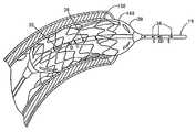
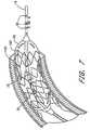
- FIG. 7illustrates balloon distension of a stent into the lumen of the coronary artery
- FIG. 8Billustrates the voltage recorded by a conductance catheter with a radius of 0.55 mm for various size vessels (vessel radii of 3.1, 2.7, 2.3, 1.9, 1.5 and 0.55 mm for the six curves, respectively) when a 1.5% NaCl bolus is injected into the treatment site;
- FIG. 9shows a photograph of a segment of swine carotid artery used for performing ex-vivo validation of the algorithm of the present disclosure
- FIG. 10shows ex-vivo data using a two-injection method of the present disclosure
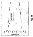
- FIG. 12shows in-vivo data using a two-injection method of the present disclosure as compared to the IVUS method.
- the disclosure of the present applicationprovides devices, systems, and methods to obtain accurate measures of the luminal cross-sectional area of organ stenosis within acceptable limits to enable accurate and scientific stent sizing and placement in order to improve clinical outcomes by avoiding under or over deployment and under or over sizing of a stent which can cause acute closure or in-stent re-stenosis.
- valve stenosismakes diagnosis of valve stenosis more accurate and more scientific by providing a direct accurate measurement of cross-sectional area of the valve annulus, independent of the flow conditions through the valve.
- Other embodimentsimprove evaluation of cross-sectional area and flow in organs like the gastrointestinal tract and the urinary tract.
- Embodiments of the disclosure of the present applicationovercome the problems associated with determination of the size (cross-sectional area) of luminal organs, such as, for example, in the coronary arteries, carotid, femoral, renal and iliac arteries, aorta, gastrointestinal tract, urethra and ureter.
- Embodimentsalso provide methods for registration of acute changes in wall conductance, such as, for example, due to edema or acute damage to the tissue, and for detection of muscle spasms/contractions.
- This catheterincludes electrodes for accurate detection of organ luminal cross-sectional area and ports for pressure gradient measurements. Hence, it is not necessary to change catheters such as with the current use of intravascular ultrasound.
- the catheterprovides direct measurement of the non-stenosed area, thereby allowing the selection of an appropriately sized stent.
- additional impedance electrodesmay be incorporated in the center of the balloon on the catheter in order to deploy the stent to the desired cross-sectional area. The procedures described herein substantially improve the accuracy of stenting and improve the cost and outcome as well.
- the impedance electrodesare embedded within a catheter to measure the valve area directly and independent of cardiac output or pressure drop and therefore minimize errors in the measurement of valve area. Hence, measurements of area are direct and not based on calculations with underlying assumptions.
- pressure sensorscan be mounted proximal and distal to the impedance electrodes to provide simultaneous pressure gradient recording.
- FIGS. 1A-1FExemplary impedance or conductance catheters for use within the disclosure of the present application are illustrated in FIGS. 1A-1F .
- electrodes 26 and 28are spaced 1 mm apart and form the inner (detection) electrodes.
- Electrodes 25 and 27are spaced 4-5 mm from either side of the inner electrodes and form the outer (excitation) electrodes. It can be appreciated that catheters of various sizes and including electrodes positioned in various locations may be useful in accordance with the present disclosure.
- dimensions of a catheter to be used for any given applicationdepend on the optimization of the potential field using finite element analysis described below.
- the diameter of the cathetermay be as small as 0.3 mm. In large organs the diameter may be significantly larger depending on the results of the optimization based on finite element analysis.
- the balloon sizewill typically be sized according to the preferred dimension of the organ after the distension.
- the balloonmay be made of materials, such as, for example, polyethylene, latex, polyestherurethane, or combinations thereof.
- the thickness of the balloonwill typically be on the order of a few microns.
- the catheterwill typically be made of PVC or polyethylene, though other materials may equally well be used.
- the excitation and detection electrodestypically surround the catheter as ring electrodes but they may also be point electrodes or have other suitable configurations. These electrodes may be made of any conductive material, preferably of platinum iridium or a carbon-coasted surface to avoid fibrin deposits. In a preferred embodiment, the detection electrodes are spaced with 0.5-1 mm between them and with a distance between 4-7 mm to the excitation electrodes on small catheters.
- the dimensions of the catheter selected for a treatmentdepend on the size of the vessel and are preferably determined in part on the results of finite element analysis, described below. On large catheters, for use in larger vessels and other visceral hollow organs, the electrode distances may be larger.
- FIGS. 1A , 1 B, 1 C, and 1 Dseveral embodiments of the catheters are illustrated.
- the catheters showncontain to a varying degree different electrodes, number and optional balloon(s).
- an impedance catheter 20with 4 electrodes 25 , 26 , 27 , and 28 placed close to the tip 19 of the catheter. Proximal to these electrodes is an angiography or stenting balloon 30 capable of being used for treating stenosis.
- Electrodes 25 and 27are excitation electrodes, while electrodes 26 and 28 are detection electrodes, which allow measurement of cross-sectional area during advancement of the catheter, as described in further detail below.
- the portion of the catheter 20 within balloon 30includes an infusion port 35 and a pressure port 36 .
- the catheter 20may also advantageously include several miniature pressure transducers (not shown) carried by the catheter or pressure ports for determining the pressure gradient proximal at the site where the cross-sectional area is measured.
- the pressureis preferably measured inside the balloon and proximal, distal to and at the location of the cross-sectional area measurement, and locations proximal and distal thereto, thereby enabling the measurement of pressure recordings at the site of stenosis and also the measurement of pressure-difference along or near the stenosis.
- catheter 20advantageously includes pressure port 90 and pressure port 91 proximal to or at the site of the cross-sectional measurement for evaluation of pressure gradients. As described below with reference to FIGS.
- the pressure portsare connected by respective conduits in the catheter 20 to pressure sensors in the data acquisition system 100 .
- pressure sensorsare well known in the art and include, for example, fiber-optic systems, miniature strain gauges, and perfused low-compliance manometry.
- a fluid-filled silastic pressure-monitoring catheteris connected to a pressure transducer.
- Luminal pressurecan be monitored by a low compliance external pressure transducer coupled to the infusion channel of the catheter.
- Pressure transducer calibrationwas carried out by applying 0 and 100 mmHg of pressure by means of a hydrostatic column.
- the catheter 39includes another set of excitation electrodes 40 , 41 and detection electrodes 42 , 43 located inside the angioplastic or stenting balloon 30 for accurate determination of the balloon cross-sectional area during angioplasty or stent deployment. These electrodes are in addition to electrodes 25 , 26 , 27 , and 28 .
- the cross-sectional areamay be measured using a two-electrode system.
- several cross-sectional areascan be measured using an array of 5 or more electrodes.
- the excitation electrodes 51 , 52are used to generate the current while detection electrodes 53 , 54 , 55 , 56 , and 57 are used to detect the current at their respective sites.
- the tip of the cathetercan be straight, curved or with an angle to facilitate insertion into the coronary arteries or other lumens, such as, for example, the biliary tract.
- the distance between the balloon and the electrodesis usually small, in the 0.5-2 cm range but can be closer or further away, depending on the particular application or treatment involved.
- the catheter 21has one or more imaging or recording devices, such as, for example, ultrasound transducers 50 for cross-sectional area and wall thickness measurements. As shown in this embodiment, the transducers 50 are located near the distal tip 19 of the catheter 21 .
- FIG. 1Dillustrates an embodiment of impedance catheter 22 without an angioplastic or stenting balloon.
- the catheter in this exemplary embodimentalso possesses an infusion or injection port 35 located proximal relative to the excitation electrode 25 and pressure port 36 .
- the electrodes 25 , 26 , 27 , and 28can also be built onto a wire 18 , such as, for example, a pressure wire, and inserted through a guide catheter 23 where the infusion of bolus can be made through the lumen of the guide catheter 37 .
- a wire 18such as, for example, a pressure wire
- the impedance catheteradvantageously includes optional ports 35 , 36 , and 37 for suction of contents of the organ or infusion of fluid.
- the suction/infusion ports 35 , 36 , and 37can be placed as shown with the balloon or elsewhere both proximal or distal to the balloon on the catheter.
- the fluid inside the ballooncan be any biologically compatible conducting fluid.
- the fluid to inject through the infusion port or portscan be any biologically compatible fluid but the conductivity of the fluid is selected to be different from that of blood (e.g., NaCl).
- the operation of the impedance catheter 20is as follows: With reference to the embodiment shown in FIG. 1A for electrodes 25 , 26 , 27 , and 28 , conductance of current flow through the organ lumen and organ wall and surrounding tissue is parallel; i.e.,
- G ⁇ ( z , t )CSA ⁇ ( z , t ) ⁇ C b L + G p ⁇ ( z , t ) [ 1 ⁇ a ]
- G p (z,t)is the effective conductance of the structure outside the bodily fluid (organ wall and surrounding tissue) at a given position, z, along the long axis of the organ at a given time
- C bis the electrical conductivity of the bodily fluid which for blood generally depends on the temperature, hematocrit and orientation and deformation of blood cells
- Lis the distance between the detection electrodes. Equation [1a] can be rearranged to solve for cross sectional area CSA(t), with a correction factor, ⁇ , if the electric field is non-homogeneous, as
- CSA ⁇ ( z , t )L ⁇ ⁇ ⁇ C b ⁇ [ G ⁇ ( z , t ) - G p ⁇ ( z , t ) ] [ 1 ⁇ b ]
- awould be equal to 1 if the field were completely homogeneous.
- the parallel conductance, G pis an offset error that results from current leakage.
- G pwould equal 0 if all of the current were confined to the blood (e.g., insulated) and hence would correspond to the cylindrical model given by Equation [10].
- finite element analysisis used to properly design the spacing between detection and excitation electrodes relative to the dimensions of the vessel to provide a nearly homogenous field such that a can be considered equal to 1.
- Simulationsshow that a homogenous or substantially homogenous field is provided by (1) the placement of detection electrodes substantially equidistant from the excitation electrodes and (2) maintaining the distance between the detection and excitation electrodes substantially comparable to the vessel diameter.
- a homogeneous fieldis achieved by taking steps (1) and/or (2) described above so that a equals 1 in the foregoing analysis.
- C kFor each injection k, C k gives rise to G k which is measured as the ratio of the root mean square of the current divided by the root mean square of the voltage.
- the C kis typically determined through in vitro calibration for the various NaCl concentrations and/or conductivities.
- concentration of NaCl usedis typically on the order of 0.45 to 1.8%.
- the volume of NaCl solutionis typically about 5 ml, but sufficient to displace the entire local vascular blood volume momentarily.
- the values of CSA(t) and G p (t)can be determined at end-diastole or end-systole (i.e., the minimum and maximum values) or the mean thereof.
- Equation [1a]allows the calculation of the electrical conductivity of blood in the presence of blood blow as
- Equation [1b]can be used to calculate the CSA continuously (temporal variation as for example through the cardiac cycle) in the presence of blood.
- Equation [1b]can be expressed as
- CSA 1 ⁇ ( U ⁇ T 1 , t )L C 1 ⁇ [ G 1 ⁇ ( U ⁇ T 1 , t ) - G p ⁇ ⁇ 1 ⁇ ( U ⁇ T 1 , t ) ] [ 8 ⁇ a ]
- CSA 1 ⁇ ( U ⁇ T 1 , t )L C 2 ⁇ [ G 2 ⁇ ( U ⁇ T 1 , t ) - G p ⁇ ⁇ 1 ⁇ ( U ⁇ T 1 , t ) ] ⁇ ⁇ and [ 8 ⁇ b ]
- CSA 2 ⁇ ( U ⁇ T 2 , t )L C 1 ⁇ [ G 1 ⁇ ( U ⁇ T 2 , t ) - G p ⁇ ⁇ 2 ⁇ ( U ⁇ T 2 , t ) ] [ 9 ⁇ a ]
- CSA 2 ⁇ ( U ⁇ T 2 , t )L C 2 ⁇ [ G
- each set of equations [8a], [8b] and [9a], [9b], etc.can be solved for CSA 1 , G p1 , and CSA 2 , G p2 , respectively.
- the CSA at various time intervalsmay be measured and hence of different positions along the vessel to reconstruct the length of the vessel.
- the data on the CSA and parallel conductance as a function of longitudinal position along the vesselcan be exported from an electronic spreadsheet, such as, for example, an Excel file, to AutoCAD where the software uses the coordinates to render a profile on the monitor.
- the excitation and detection electrodesare electrically connected to electrically conductive leads in the catheter for connecting the electrodes to the data acquisition system 100 .
- FIGS. 2A and 2Billustrate two embodiments 20 A and 20 B of the catheter in cross-section.
- Each embodimenthas a lumen 60 for inflating and deflating the balloon and a lumen 61 for suction and infusion.
- the sizes of these lumenscan vary in size.
- the impedance electrode electrical leads 70 Aare embedded in the material of the catheter in the embodiment in FIG. 2A , whereas the electrode electrical leads 70 B are tunneled through a lumen 71 formed within the body of catheter 70 B in FIG. 2B .
- Pressure conduits for perfusion manometryconnect the pressure ports 90 , 91 to transducers included in the data acquisition system 100 .
- pressure conduits 95 Amay be formed in 20 A.
- pressure conduits 95 Bconstitute individual conduits within a tunnel 96 formed in catheter 20 B. In the embodiment described above where miniature pressure transducers are carried by the catheter, electrical conductors will be substituted for these pressure conduits.
- the catheter 20connects to a data acquisition system 100 , to a manual or automatic system 105 for distension of the balloon and to a system 106 for infusion of fluid or suction of blood.
- the fluidwill be heated to 37-39° or equivalent to body temperature with heating unit 107 .
- the impedance planimetry systemtypically includes a constant current unit, amplifiers and signal conditioners.
- the pressure systemtypically includes amplifiers and signal conditioners.
- the systemcan optionally contain signal conditioning equipment for recording of fluid flow in the organ.
- the systemis pre-calibrated and the probe is available in a package.
- the packagealso preferably contains sterile syringes with the fluids to be injected.
- the syringesare attached to the machine and after heating of the fluid by the machine and placement of the probe in the organ of interest, the user presses a button that initiates the injection with subsequent computation of the desired parameters.
- the cross-sectional area, CSA, and parallel conductance, G p , and other relevant measures such as distensibility, tension, etc.will typically appear on the display panel in the PC module 160 .
- the usercan then remove the stenosis by distension or by placement of a stent.
- the systemcan contain a multiplexer unit or a switch between CSA channels.
- each CSA measurementwill be through separate amplifier units. The same may account for the pressure channels.
- the impedance and pressure dataare analog signals which are converted by analog-to-digital converters 150 and transmitted to a computer 160 for on-line display, on-line analysis and storage. In another embodiment, all data handling is done on an entirely analog basis.
- the analysisadvantageously includes software programs for reducing the error due to conductance of current in the organ wall and surrounding tissue and for displaying profile of the CSA distribution along the length of the vessel along with the pressure gradient.
- a finite element approach or a finite difference approachis used to derive the CSA of the organ stenosis taking parameters such as conductivities of the fluid in the organ and of the organ wall and surrounding tissue into consideration.
- the softwarecontains the code for reducing the error in luminal CSA measurement by analyzing signals during interventions such as infusion of a fluid into the organ or by changing the amplitude or frequency of the current from the constant current amplifier.
- the software chosen for a particular applicationpreferably allows computation of the CSA with only a small error instantly or within acceptable time during the medical procedure.
- the wall thicknessis determined from the parallel conductance for those organs that are surrounded by air or non-conducting tissue. In such cases, the parallel conductance is equal to
- the compliancee.g., ⁇ CSA/ ⁇ P
- tensione.g., P ⁇ r, where P and r are the intraluminal pressure and radius of a cylindrical organ
- stresse.g., P ⁇ r/h where h is the wall thickness of the cylindrical organ
- straine.g., (C ⁇ C d /C d where C is the inner circumference and C d is the circumference in diastole
- wall shear stresse.g., 4 ⁇ Q/r 3 where ⁇ , Q and r are the fluid viscosity, flow rate and radius of the cylindrical organ, respectively, for a fully developed flow.
- luminal cross-sectional areais measured by introducing a catheter from an exteriorly accessible opening (e.g., mouth, nose, or anus for GI applications; or e.g., mouth or nose for airway applications) into the hollow system or targeted luminal organ.
- an exteriorly accessible openinge.g., mouth, nose, or anus for GI applications; or e.g., mouth or nose for airway applications
- the cathetercan be inserted into the organs in various ways; e.g., similar to conventional angioplasty.
- an 18 gauge needleis inserted into the femoral artery followed by an introducer.
- a guide wireis then inserted into the introducer and advanced into the lumen of the femoral artery.
- a 4 or 5 Fr conductance catheteris then inserted into the femoral artery via wire and the wire is subsequently retracted.
- the catheter tip containing the conductance electrodescan then be advanced to the region of interest by use of x-ray (i.e., fluoroscopy).
- x-rayi.e., fluoroscopy
- this methodologyis used on small to medium size vessels (e.g., femoral, coronary, carotid, iliac arteries, etc.).
- a minimum of two injectionsare required to solve for the two unknowns, CSA and G p .
- three injectionswill yield three set of values for CSA and G p (although not necessarily linearly independent), while four injections would yield six set of values.
- at least two solutionse.g., 0.5% and 1.5% NaCl solutions
- Our studiesindicate that an infusion rate of approximately 1 ml/s for a five second interval is sufficient to displace the blood volume and results in a local pressure increase of less than 10 mmHg in the coronary artery. This pressure change depends on the injection rate which should be comparable to the organ flow rate.
- the vesselis under identical or very similar conditions during the two injections.
- variablessuch as, for example, the infusion rate, bolus temperature, etc.
- a short time intervalis to be allowed (1-2 minute period) between the two injections to permit the vessel to return to homeostatic state. This can be determined from the baseline conductance as shown in FIG. 4 or 5 .
- the parallel conductanceis preferably the same or very similar during the two injections.
- dextran, albumin or another large molecular weight moleculecan be added to the NaCl solutions to maintain the colloid osmotic pressure of the solution to reduce or prevent fluid or ion exchange through the vessel wall.
- the NaCl solutionis heated to body temperature prior to injection since the conductivity of current is temperature dependent.
- the injected bolusis at room temperature, but a temperature correction is made since the conductivity is related to temperature in a linear fashion.
- a sheathis inserted either through the femoral or carotid artery in the direction of flow.
- the sheathis inserted through the ascending aorta.
- a catheter having a diameter of 1.9 mmcan be used, as determined from finite element analysis, discussed further below.
- the femoral and coronary arterieswhere the diameter is typically in the range from 3.5-4 mm, so a catheter of about 0.8 mm diameter would be appropriate.
- the cathetercan be inserted into the femoral, carotid or LAD artery through a sheath appropriate for the particular treatment. Measurements for all three vessels can be made similarly.
- the conductance catheterwas inserted through the sheath for a particular vessel of interest.
- a baseline reading of voltagewas continuously recorded.
- Two containers containing 0.5% and 1.5% NaClwere placed in temperature bath and maintained at 37°.
- a 5-10 ml injection of 1.5% NaClwas made over a 5 second interval.
- the detection voltagewas continuously recorded over a 10 second interval during the 5 second injection.
- a similar volume of 1.5% NaCl solutionwas injected at a similar rate.
- Matlabwas used to analyze the data including filtering with high pass and with low cut off frequency (1200 Hz).
- FIGS. 4A , 4 B, 5 A and 5 Billustrate voltage measurements in the blood stream in the left carotid artery.
- the data acquisitionhad a the sampling frequency of 75 KHz, with two channels—the current injected and the detected voltage, respectively.
- the current injectedhas a frequency of 5 KHz, so the voltage detected, modulated in amplitude by the impedance changing through the bolus injection will have a spectrum in the vicinity of 5 KHz.
- FIG. 4Athere is shown a signal processed with a high pass filter with low cut off frequency (1200 Hz).
- the top and bottom portions 200 , 202show the peak-to-peak envelope detected voltage which is displayed in FIG. 4B (bottom).
- the initial 7 secondscorrespond to the baseline; i.e., electrodes in the blood stream.
- the next 7 secondscorrespond to an injection of hyper-osmotic NaCl solution (1.5% NaCl). It can be seen that the voltage is decreased implying increase conductance (since the injected current is constant).
- the baselineis recovered as can be seen in the last portion of the FIGS. 4A and 4B .
- FIGS. 5A and 5Bshows similar data corresponding to 0.5% NaCl solutions.
- the voltage signalsare ideal since the difference between the baseline and the injected solution is apparent and systematic. Furthermore, the pulsation of vessel diameter can be seen in the 0.5% and 1.5% NaCl injections ( FIGS. 4 and 5 , respectively). This allows determination of the variation of CSA throughout the cardiac cycle as outline above.
- the NaCl solutioncan be injected by hand or by using a mechanical injector to momentarily displace the entire volume of blood or bodily fluid in the vessel segment of interest.
- the pressure generated by the injectionwill not only displace the blood in the antegrade direction (in the direction of blood flow) but also in the retrograde direction (momentarily push the blood backwards).
- the NaCl solutionwill not displace blood as in the vessels but will merely open the organs and create a flow of the fluid.
- sensorsmonitor and confirm baseline of conductance prior to injection of a second solution into the treatment site.
- the injections described aboveare preferably repeated at least once to reduce errors associated with the administration of the injections, such as, for example, where the injection does not completely displace the blood or where there is significant mixing with blood.
- any bifurcation(s)(with branching angle near 90 degrees) near the targeted luminal organ can cause an overestimation of the calculated CSA.
- the cathetershould be slightly retracted or advanced and the measurement repeated.
- An additional application with multiple detection electrodes or a pull back or push forward during injectionwill accomplish the same goal.
- an array of detection electrodescan be used to minimize or eliminate errors that would result from bifurcations or branching in the measurement or treatment site.
- error due to the eccentric position of the electrode or other imaging devicecan be reduced by inflation of a balloon on the catheter.
- the inflation of balloon during measurementwill place the electrodes or other imaging device in the center of the vessel away from the wall.
- the inflation of ballooncan be synchronized with the injection of bolus where the balloon inflation would immediately precede the bolus injection.
- the CSA predicted by Equation [4]corresponds to the area of the vessel or organ external to the catheter (i.e., CSA of vessel minus CSA of catheter). If the conductivity of the NaCl solutions is determined by calibration from Equation [10] with various tubes of known CSA, then the calibration accounts for the dimension of the catheter and the calculated CSA corresponds to that of the total vessel lumen as desired. In one embodiment, the calibration of the CSA measurement system will be performed at 37° C. by applying 100 mmHg in a solid polyphenolenoxide block with holes of known CSA ranging from 7.065 mm 2 (3 mm in diameter) to 1017 mm 2 (36 mm in diameter). If the conductivity of the solutions is obtained from a conductivity meter independent of the catheter, however, then the CSA of the catheter is generally added to the CSA computed from Equation [4] to give the desired total CSA of the vessel.
- the signalsare generally non-stationary, nonlinear and stochastic.
- Spectrogramthe Wavelet's analysis, the Wigner-Ville distribution, the Evolutionary Spectrum, Modal analysis, or preferably the intrinsic model function (IMF) method.
- IMFintrinsic model function
- the mean or peak-to-peak valuescan be systematically determined by the aforementioned signal analysis and used in Equation [4] to compute the CSA.
- a four-injection approachis provided. As previously disclosed herein, two injections provide the cross-sectional area, CSA, and parallel conductance, G p , at a particular point.
- four injectionsare provided to determine parallel conductance at multiple points.
- four injectionsmay be performed to determine a segment of 2-3 cm long or longer.
- two injectionsmay be performed at the distal end of the segment, and two injections may be performed at the proximal end of the segment.
- the two injectionsmay deliver, for example, a volume of 1.5% NaCl and a volume of 0.5% NaCl, at each end of the segment, noting that any number of solutions, volumes, and concentrations thereof suitable for such a study, or for the other studies contemplated by the disclosure of the present application, could be utilized.
- solutions having different salinitiescan be introduced in various physiological saline solutions (PSS) or in a Kreb solution containing other ions such as potassium, sodium, etc.
- PSSphysiological saline solutions
- Kreb solution containing other ionssuch as potassium, sodium, etc.
- the first two injections(1.5% NaCl and 0.5% NaCl) may be made at the distal point of the segment, and the catheter system would then be pulled back to the proximal point of the segment, whereby two more injections (1.5% NaCl and 0.5% NaCl) may be made, with conductance values taken at the distal end and the proximal end of the segment used to determine the entire profile of the segment.
- conductancemay be calculated taking into account cross-sectional area, electrical conductivity of a fluid, and effective conductance of a structure.
- the two end pointsproximal and distal ends of a segment
- an intermediate profile between those two pointscan be derived based upon the analysis provided herein.
- the cross-sectional area, CSA, and parallel conductance at a point, G pare known at each of the two ends of a segment, the corresponding blood conductivity may be calculated:
- G TotalCSA ⁇ C b L + G p [ 13 ⁇ a ]
- G Totalis the total conductance (current divided by voltage)
- CSAis the cross-sectional area
- C bis the blood conductivity
- Lis the detection electrode spacing on the catheter
- G pis the parallel conductance at a point. The mean of the two values may then be calculated based upon the foregoing.
- a procedure as described abovemay be accomplished, for example, by performing the following steps:
- G Totalis the total conductance
- Iis the current
- Vis the voltage
- CSAis the cross-sectional area
- ⁇is the conductivity of the fluid
- Lis the detection electrode spacing on the catheter
- G pis the parallel conductance at a point.
- G totalis the total conductance
- Iis the current
- Vis the voltage
- CSAis the cross-sectional area
- ⁇is the conductivity of the fluid
- Lis the detection electrode spacing on the catheter
- mis the slope
- bis the intercept as can be determined for a linear least square fit. This may be rearranged as follows:
- Diameter4 * CSA ⁇ [ 19 ] to determine a diameter.
- a three-injection approach to determine a profile as outlined above with respect to the four-injection approachis also provided.
- three injectionsare provided, with two injections at the distal end of a segment, simultaneous withdrawal of one of the injection sources, and one injection at the proximal end of the segment.
- the first two injections at the distal endmay deliver, for example, a volume of 1.5% NaCl and a volume of 0.5% NaCl, noting that any number of solutions, volumes, and concentrations thereof suitable for such a study could be utilized.
- the first two injections (1.5% NaCl and 0.5% NaCl)may be made at the distal point of the segment, wherein the catheter system is simultaneously withdrawn with the injection of the 0.5% NaCl so that the 0.5% NaCl may also be used for the proximal end. These injections would then be followed by a 1.5% NaCl injection at the proximal end of the segment.
- the conductivitywould be simplified as that of 0.5% rather than blood, and (2) there are only three injections required instead of four.
- the three-injection methodalso requires that a physician using a catheter system to perform such a procedure would be required to inject and pull back simultaneously. A physician comfortable with simultaneous injection and pull back may prefer the three-injection approach, while a physician not comfortable with simultaneous injection and pull back may prefer the four-injection approach. Either approach is possible using the algorithm provided herein.
- the LumenRecon systemwas calibrated using the 0.45% and 1.5% saline concentrations.
- a two-injection method according to the present disclosurewas used to make single diameter measurements at the six locations along the length of the vessel. “Pull back” measurements were also made along the length of the vessel to create a continuous profile of the vessel diameter.
- a cast mold of the vesselwas created.
- the diameter of the cast mold of the vesselwas determined using microscopy.
- the cast measurementswere taken at the six locations marked by the black indicator and at intermediate locations along the vessel.
- FIG. 10shows the data for the six locations using a two-injection method of the present disclosure, comparing the diameters calculated by the LumenRecon system to those measured from the cast mold of the vessel using microscopy.
- FIG. 11shows a profile of data points (diameters) using a pull back method of the present disclosure, comparing the diameters calculated by the LumenRecon system to those measured from the cast mold of the vessel using microscopy.
- the LumenRecon systemwas used to make measurements in the left anterior descending (LAD) coronary artery in an anesthesized swine.
- a two-injection method of the present disclosurewas used to construct a profile which was compared to IVUS at four different locations along the profile.
- FIG. 12shows the LumenRecon measurements plotted against the IVUS measurements, showing the measurements before and after the temperature correction.
- the temperature correctionwas incorporated into the calibration of the catheter. It was determined that a NaCl solution injected at room temperature (25° C.) reaches 30° C. when at the body site of measurement (39° C.). Hence, calibrations of fluid were made at 30° C. to account for the heating of the fluid during injection.
- the angioplasty balloon 30is shown distended within the coronary artery 150 for the treatment of stenosis. As described above with reference to FIG. 1B , a set of excitation electrodes 40 , 41 and detection electrodes 42 , 43 are located within the angioplasty balloon 30 . In another embodiment, shown in FIG. 7 , the angioplasty balloon 30 is used to distend the stent 160 within blood vessel 150 .
- the two pressure sensors 36are advantageously placed immediately proximal and distal to the detection electrodes (1-2 mm above and below, respectively) or several sets of detection electrodes (see, e.g., FIGS. 1D and 1F ).
- the pressure readingswill then indicate the position of the detection electrode relative to the desired site of measurement (aortic valve: aortic-ventricular pressure; mitral valve: left ventricular-atrial pressure; tricuspid valve: right atrial-ventricular pressure; pulmonary valve: right ventricular-pulmonary pressure).
- aortic valveaortic-ventricular pressure
- mitral valveleft ventricular-atrial pressure
- tricuspid valveright atrial-ventricular pressure
- pulmonary valveright ventricular-pulmonary pressure
- the parallel conductance at the site of annulusis generally expected to be small since the annulus consists primarily of collagen which has low electrical conductivity.
- a pull back or push forward through the heart chamberwill show different conductance due to the change in geometry and parallel conductance. This can be established for normal patients which can then be used to diagnose valvular stensosis.
- the procedurescan conveniently be done by swallowing fluids of known conductances into the esophagus and infusion of fluids of known conductances into the urinary bladder followed by voiding the volume.
- fluidscan be swallowed or urine voided followed by measurement of the fluid conductances from samples of the fluid.
- the latter methodcan be applied to the ureter where a catheter can be advanced up into the ureter and fluids can either be injected from a proximal port on the probe (will also be applicable in the intestines) or urine production can be increased and samples taken distal in the ureter during passage of the bolus or from the urinary bladder.
- concomitant with measuring the cross-sectional area and or pressure gradient at the treatment or measurement sitea mechanical stimulus is introduced by way of inflating the balloon or by releasing a stent from the catheter, thereby facilitating flow through the stenosed part of the organ.
- one or more pharmaceutical substances for diagnosis or treatment of stenosisis injected into the treatment site.
- the injected substancecan be smooth muscle agonist or antagonist.
- concomitant with measuring the cross-sectional area and or pressure gradient at the treatment sitean inflating fluid is released into the treatment site for release of any stenosis or materials causing stenosis in the organ or treatment site.
- the methods, systems, and devices described hereincan be applied to any body lumen or treatment site.
- the methods, systems, and devices described hereincan be applied to any one of the following exemplary bodily hollow systems: the cardiovascular system including the heart; the digestive system; the respiratory system; the reproductive system; and the urogential tract.
- Finite Element AnalysisIn one preferred approach, finite element analysis (FEA) is used to verify the validity of Equations [4] and [5]. There are two major considerations for the model definition: geometry and electrical properties.
- Poisson's equation for the potential fieldwas solved, taking into account the magnitude of the applied current, the location of the current driving and detection electrodes, and the conductivities and geometrical shapes in the model including the vessel wall and surrounding tissue.
- This analysissuggest that the following conditions are optimal for the cylindrical model: (1) the placement of detection electrodes equidistant from the excitation electrodes; (2) the distance between the current driving electrodes should be much greater than the distance between the voltage sensing electrodes; and (3) the distance between the detection and excitation electrodes is comparable to the vessel diameter or the diameter of the vessel is small relative to the distance between the driving electrodes.
- the equipotential contoursmore closely resemble straight lines perpendicular to the axis of the catheter and the voltage drop measured at the wall will be nearly identical to that at the center. Since the curvature of the equipotential contours is inversely related to the homogeneity of the electric field, it is possible to optimize the design to minimize the curvature of the field lines. Consequently, in one preferred approach, one or more of conditions (1)-(3) described above are met to increase the accuracy of the cylindrical model.
- the isopotential lineis not constant as one moves out radially along the vessel as stipulated by the cylindrical model.
- a catheter with a radius of 0.55 mmis considered whose detected voltage is shown in FIGS. 8A and 8B for two different NaCl solutions (0.5% and 1.5%, respectively).
- the origincorresponds to the center of the catheter.
- the first vertical line 220represents the inner part of the electrode which is wrapped around the catheter and the second vertical line 221 is the outer part of the electrode in contact with the solution (diameter of electrode is approximately 0.25 mm).
- the six different curves, top to bottom,correspond to six different vessels with radii of 3.1, 2.7, 2.3, 1.9, 1.5, and 0.55 mm, respectively. It can be seen that a “hill” occurs at the detection electrode 220 , 221 followed by a fairly uniform plateau in the vessel lumen followed by an exponential decay into the surrounding tissue. Since the potential difference is measured at the detection electrode 220 , 221 , the simulation generates the “hill” whose value corresponds to the equivalent potential in the vessel as used in Eq. [4]. Hence, for each catheter size, the dimension of the vessel was varied such that equation [4] is exactly satisfied.
- different diameter cathetersare prepackaged and labeled for optimal use in certain size vessel.
- vessel dimensionin the range of 4-5 mm, 5-7 mm or 7-10 mm
- analysis in accordance with the disclosure of the present applicationshows that the optimum diameter catheters will be in the range of 0.9-1.4, 1.4-2.0 or 2.04.6 mm, respectively.
- a cliniciancan select the appropriate diameter catheter based on the estimated vessel diameter of interest. This decision will be made prior to the procedure and will serve to minimize the error in the determination of lumen CSA.
- cathetersincluding, but not limited to, impedance and/or guide catheters, and wires, including, but not limited to, impedance wires, guide wires, pressure wires, and flow wires, may be used as appropriate as devices, systems, and/or portions of systems of the present disclosure, and may be used as appropriate to perform one or more methods, or steps thereof, of the present disclosure.
- the disclosuremay have presented a method and/or process as a particular sequence of steps.
- the method or processshould not be limited to the particular sequence of steps described.
- other sequences of stepsmay be possible. Therefore, the particular order of the steps disclosed herein should not be construed as limitations on the claims.
- the claims directed to a method and/or processshould not be limited to the performance of their steps in the order written, and one skilled in the art can readily appreciate that the sequences may be varied and still remain within the spirit and scope of the present disclosure.
Landscapes
- Health & Medical Sciences (AREA)
- Life Sciences & Earth Sciences (AREA)
- Molecular Biology (AREA)
- Surgery (AREA)
- Physics & Mathematics (AREA)
- Veterinary Medicine (AREA)
- Biophysics (AREA)
- Pathology (AREA)
- Engineering & Computer Science (AREA)
- Biomedical Technology (AREA)
- Heart & Thoracic Surgery (AREA)
- Animal Behavior & Ethology (AREA)
- Public Health (AREA)
- General Health & Medical Sciences (AREA)
- Medical Informatics (AREA)
- Nuclear Medicine, Radiotherapy & Molecular Imaging (AREA)
- Radiology & Medical Imaging (AREA)
- Physiology (AREA)
- Cardiology (AREA)
- Dentistry (AREA)
- Oral & Maxillofacial Surgery (AREA)
- Vascular Medicine (AREA)
- Hematology (AREA)
- Media Introduction/Drainage Providing Device (AREA)
Abstract
Description
where Gp(z,t) is the effective conductance of the structure outside the bodily fluid (organ wall and surrounding tissue) at a given position, z, along the long axis of the organ at a given time, t, and Cbis the electrical conductivity of the bodily fluid which for blood generally depends on the temperature, hematocrit and orientation and deformation of blood cells, and L is the distance between the detection electrodes. Equation [1a] can be rearranged to solve for cross sectional area CSA(t), with a correction factor, α, if the electric field is non-homogeneous, as
where a would be equal to 1 if the field were completely homogeneous. The parallel conductance, Gp, is an offset error that results from current leakage. Gpwould equal 0 if all of the current were confined to the blood (e.g., insulated) and hence would correspond to the cylindrical model given by Equation [10]. In one approach, finite element analysis is used to properly design the spacing between detection and excitation electrodes relative to the dimensions of the vessel to provide a nearly homogenous field such that a can be considered equal to 1. Simulations show that a homogenous or substantially homogenous field is provided by (1) the placement of detection electrodes substantially equidistant from the excitation electrodes and (2) maintaining the distance between the detection and excitation electrodes substantially comparable to the vessel diameter. In one approach, a homogeneous field is achieved by taking steps (1) and/or (2) described above so that a equals 1 in the foregoing analysis.
C1·CSA(z,t)+L·Gp(z,t)=L·G1(z,t) [2]
and
C2·CSA(z,t)+L·Gp(z,t)=L·G2(z,t) [3]
which can be solved simultaneously for CSA and Gpas
where subscript “1” and subscript “2” designate any two injections of different NaCl concentrations and/or conductivities. For each injection k, Ckgives rise to Gkwhich is measured as the ratio of the root mean square of the current divided by the root mean square of the voltage. The Ckis typically determined through in vitro calibration for the various NaCl concentrations and/or conductivities. The concentration of NaCl used is typically on the order of 0.45 to 1.8%. The volume of NaCl solution is typically about 5 ml, but sufficient to displace the entire local vascular blood volume momentarily. The values of CSA(t) and Gp(t) can be determined at end-diastole or end-systole (i.e., the minimum and maximum values) or the mean thereof.
In this way, Equation [1b] can be used to calculate the CSA continuously (temporal variation as for example through the cardiac cycle) in the presence of blood.
where the axial position, z, is the product of catheter velocity, U, and time, t; i.e., z=U·t.
and so on. Each set of equations [8a], [8b] and [9a], [9b], etc. can be solved for CSA1, Gp1, and CSA2, Gp2, respectively. Hence, the CSA at various time intervals may be measured and hence of different positions along the vessel to reconstruct the length of the vessel. In one embodiment, the data on the CSA and parallel conductance as a function of longitudinal position along the vessel can be exported from an electronic spreadsheet, such as, for example, an Excel file, to AutoCAD where the software uses the coordinates to render a profile on the monitor.
where G is conductance expressed as the ratio of current to voltage, I/ΔV. Equation [10] is identical to Equation [1b] if the parallel conductance through the vessel wall is neglected and surrounding tissue because the balloon material acts as an insulator. This is the cylindrical model on which the conductance method is used.
where CSAwis the wall area of the organ and Cwis the electrical conductivity through the wall. This equation can be solved for the wall CSAwas
For a cylindrical organ, the wall thickness, h, can be expressed as
where D is the diameter of the vessel which can be determined from the circular CSA (D=[4CSA/π]1/2).
where GTotalis the total conductance (current divided by voltage), CSA is the cross-sectional area, Cbis the blood conductivity, L is the detection electrode spacing on the catheter, and Gpis the parallel conductance at a point. The mean of the two values may then be calculated based upon the foregoing.
- Step 1: Calculate total conductance (GTotal, current divided by voltage, or I/V, where I is the current injected and V is the voltage recorded) for two ends (proximal and distal) of a segment.
- Step 2: Calculate the Coeff ratio (cross-sectional area divided by total conductance, or CSA/GTotal) at the two ends of the segment.
- Step 3: Linearly interpolate along the length of the pull back for the Coeff, so that the two ends of the segment have the same Coeffs calculated from
Step 2 above. - Step 4: Calculate total conductance (GTotal) for the entire length of the pull back (distance between the two ends of the segment).
- Step 5: At each point calculated in the pull back, multiply the total conductance (GTotal) times its respective Coeff. The product of this calculation is the cross-sectional area (CSA).
- Step 6: Determine the diameter from the cross-sectional area (CSA) along the entire profile.
where GTotalis the total conductance, I is the current, V is the voltage, CSA is the cross-sectional area, σ is the conductivity of the fluid, L is the detection electrode spacing on the catheter, and Gpis the parallel conductance at a point.
where Gtotalis the total conductance, I is the current, V is the voltage, CSA is the cross-sectional area, σ is the conductivity of the fluid, L is the detection electrode spacing on the catheter, m is the slope, and b is the intercept as can be determined for a linear least square fit. This may be rearranged as follows:
CSA=Coeff*GTotal [18]
and
to determine a diameter.
Exemplary Three-Injection Approach
∇·(C∇V)=−I [13]
where C, I, and ∇ are the conductivity, the driving current density, and the del operator, respectively. Femlab or any standard finite element packages can be used to compute the nodal voltages using equation [13]. Once V has been determined, the electric field can be obtained from as E=−∇V.
Claims (81)
Priority Applications (15)
| Application Number | Priority Date | Filing Date | Title |
|---|---|---|---|
| US12/098,242US8078274B2 (en) | 2003-02-21 | 2008-04-04 | Device, system and method for measuring cross-sectional areas in luminal organs |
| PCT/US2009/038598WO2009123930A1 (en) | 2008-04-04 | 2009-03-27 | Device, system and method for measuring cross-sectional areas in luminal organs |
| US12/426,033US8185194B2 (en) | 2003-02-21 | 2009-04-17 | Systems and methods for determining phasic cardiac cycle measurements |
| US12/426,225US8099161B2 (en) | 2003-02-21 | 2009-04-18 | Systems and methods for determining vessel compliance |
| US12/428,656US8465452B2 (en) | 2003-02-21 | 2009-04-23 | Devices, systems, and methods for removing stenotic lesions from vessels |
| US12/748,166US9603545B2 (en) | 2003-02-21 | 2010-03-26 | Devices, systems, and methods for removing targeted lesions from vessels |
| US13/324,222US9066708B2 (en) | 2003-02-21 | 2011-12-13 | Methods to generate luminal organ profiles using impedance |
| US13/920,833US9289229B2 (en) | 2003-02-21 | 2013-06-18 | Devices and methods for removing stenotic lesions from vessels |
| US14/010,139US9445743B2 (en) | 2003-02-21 | 2013-08-26 | Methods for generating luminal organ profiles using impedance |
| US14/215,012US9462960B2 (en) | 2003-02-21 | 2014-03-16 | Impedance devices and methods of using the same to obtain luminal organ measurements |
| US14/755,096US20150297111A1 (en) | 2008-04-04 | 2015-06-30 | Methods for generating luminal organ profiles using impedance |
| US15/269,767US10524685B2 (en) | 2003-02-21 | 2016-09-19 | Methods for generating luminal organ profiles using impedance |
| US15/290,919US11103152B2 (en) | 2003-02-21 | 2016-10-11 | Impedance devices and methods of using the same to obtain luminal organ measurements |
| US15/470,958US10779750B2 (en) | 2003-02-21 | 2017-03-28 | Devices, systems, and methods for removing targeted lesions from vessels |
| US17/463,480US20220054038A1 (en) | 2003-02-21 | 2021-08-31 | Impedance devices and methods of using the same to obtain luminal organ measurements |
Applications Claiming Priority (6)
| Application Number | Priority Date | Filing Date | Title |
|---|---|---|---|
| US44926603P | 2003-02-21 | 2003-02-21 | |
| US49314503P | 2003-08-07 | 2003-08-07 | |
| US50213903P | 2003-09-11 | 2003-09-11 | |
| US10/782,149US7454244B2 (en) | 2003-02-21 | 2004-02-19 | System and method for measuring cross-sectional areas and pressure gradients in luminal organs |
| US11/891,981US8114143B2 (en) | 2003-02-21 | 2007-08-14 | System and method for measuring cross-sectional areas and pressure gradients in luminal organs |
| US12/098,242US8078274B2 (en) | 2003-02-21 | 2008-04-04 | Device, system and method for measuring cross-sectional areas in luminal organs |
Related Parent Applications (1)
| Application Number | Title | Priority Date | Filing Date |
|---|---|---|---|
| US11/891,981Continuation-In-PartUS8114143B2 (en) | 2003-02-21 | 2007-08-14 | System and method for measuring cross-sectional areas and pressure gradients in luminal organs |
Related Child Applications (3)
| Application Number | Title | Priority Date | Filing Date |
|---|---|---|---|
| US12/426,033Continuation-In-PartUS8185194B2 (en) | 2003-02-21 | 2009-04-17 | Systems and methods for determining phasic cardiac cycle measurements |
| US12/428,656Continuation-In-PartUS8465452B2 (en) | 2003-02-21 | 2009-04-23 | Devices, systems, and methods for removing stenotic lesions from vessels |
| US13/324,222ContinuationUS9066708B2 (en) | 2003-02-21 | 2011-12-13 | Methods to generate luminal organ profiles using impedance |
Publications (2)
| Publication Number | Publication Date |
|---|---|
| US20080194996A1 US20080194996A1 (en) | 2008-08-14 |
| US8078274B2true US8078274B2 (en) | 2011-12-13 |
Family
ID=41135909
Family Applications (5)
| Application Number | Title | Priority Date | Filing Date |
|---|---|---|---|
| US12/098,242Active2026-04-19US8078274B2 (en) | 2003-02-21 | 2008-04-04 | Device, system and method for measuring cross-sectional areas in luminal organs |
| US13/324,222Expired - LifetimeUS9066708B2 (en) | 2003-02-21 | 2011-12-13 | Methods to generate luminal organ profiles using impedance |
| US14/010,139Expired - LifetimeUS9445743B2 (en) | 2003-02-21 | 2013-08-26 | Methods for generating luminal organ profiles using impedance |
| US14/755,096AbandonedUS20150297111A1 (en) | 2003-02-21 | 2015-06-30 | Methods for generating luminal organ profiles using impedance |
| US15/269,767Expired - LifetimeUS10524685B2 (en) | 2003-02-21 | 2016-09-19 | Methods for generating luminal organ profiles using impedance |
Family Applications After (4)
| Application Number | Title | Priority Date | Filing Date |
|---|---|---|---|
| US13/324,222Expired - LifetimeUS9066708B2 (en) | 2003-02-21 | 2011-12-13 | Methods to generate luminal organ profiles using impedance |
| US14/010,139Expired - LifetimeUS9445743B2 (en) | 2003-02-21 | 2013-08-26 | Methods for generating luminal organ profiles using impedance |
| US14/755,096AbandonedUS20150297111A1 (en) | 2003-02-21 | 2015-06-30 | Methods for generating luminal organ profiles using impedance |
| US15/269,767Expired - LifetimeUS10524685B2 (en) | 2003-02-21 | 2016-09-19 | Methods for generating luminal organ profiles using impedance |
Country Status (2)
| Country | Link |
|---|---|
| US (5) | US8078274B2 (en) |
| WO (1) | WO2009123930A1 (en) |
Cited By (54)
| Publication number | Priority date | Publication date | Assignee | Title |
|---|---|---|---|---|
| US20090204134A1 (en)* | 2003-02-21 | 2009-08-13 | Kassab Ghassan S | Devices, systems, and methods for removing stenotic lesions from vessels |
| US20100168836A1 (en)* | 2003-02-21 | 2010-07-01 | Kassab Ghassan S | Balloon sizing of valve annulus for percutaneous valves |
| US20120035642A1 (en)* | 2009-03-09 | 2012-02-09 | Flip Technologies Limited | Catheter, a balloon catheter and a method and apparatus for monitoring the transverse cross-section of a stoma |
| US20120041453A1 (en)* | 2010-08-13 | 2012-02-16 | Klaus Klingenbeck | Fastening Device for a Mitral Valve and Method |
| US20120172746A1 (en)* | 2003-02-21 | 2012-07-05 | Kassab Ghassan S | Methods to Generate Luminal Organ Profiles Using Impedance |
| US8801693B2 (en) | 2010-10-29 | 2014-08-12 | C. R. Bard, Inc. | Bioimpedance-assisted placement of a medical device |
| US9265443B2 (en) | 2006-10-23 | 2016-02-23 | Bard Access Systems, Inc. | Method of locating the tip of a central venous catheter |
| US9339206B2 (en) | 2009-06-12 | 2016-05-17 | Bard Access Systems, Inc. | Adaptor for endovascular electrocardiography |
| US9345422B2 (en) | 2006-10-23 | 2016-05-24 | Bard Acess Systems, Inc. | Method of locating the tip of a central venous catheter |
| US9445734B2 (en) | 2009-06-12 | 2016-09-20 | Bard Access Systems, Inc. | Devices and methods for endovascular electrography |
| US9456766B2 (en) | 2007-11-26 | 2016-10-04 | C. R. Bard, Inc. | Apparatus for use with needle insertion guidance system |
| US9492097B2 (en) | 2007-11-26 | 2016-11-15 | C. R. Bard, Inc. | Needle length determination and calibration for insertion guidance system |
| US9521961B2 (en) | 2007-11-26 | 2016-12-20 | C. R. Bard, Inc. | Systems and methods for guiding a medical instrument |
| US9526440B2 (en) | 2007-11-26 | 2016-12-27 | C.R. Bard, Inc. | System for placement of a catheter including a signal-generating stylet |
| US9532724B2 (en) | 2009-06-12 | 2017-01-03 | Bard Access Systems, Inc. | Apparatus and method for catheter navigation using endovascular energy mapping |
| US9549679B2 (en) | 2012-05-14 | 2017-01-24 | Acist Medical Systems, Inc. | Multiple transducer delivery device and method |
| US9549685B2 (en) | 2007-11-26 | 2017-01-24 | C. R. Bard, Inc. | Apparatus and display methods relating to intravascular placement of a catheter |
| US9554716B2 (en) | 2007-11-26 | 2017-01-31 | C. R. Bard, Inc. | Insertion guidance system for needles and medical components |
| US9636031B2 (en) | 2007-11-26 | 2017-05-02 | C.R. Bard, Inc. | Stylets for use with apparatus for intravascular placement of a catheter |
| US9649048B2 (en) | 2007-11-26 | 2017-05-16 | C. R. Bard, Inc. | Systems and methods for breaching a sterile field for intravascular placement of a catheter |
| US9681823B2 (en) | 2007-11-26 | 2017-06-20 | C. R. Bard, Inc. | Integrated system for intravascular placement of a catheter |
| US9839372B2 (en) | 2014-02-06 | 2017-12-12 | C. R. Bard, Inc. | Systems and methods for guidance and placement of an intravascular device |
| US9854981B2 (en) | 2011-10-14 | 2018-01-02 | Acist Medical Systems, Inc. | Device and methods for measuring and treating an anatomical structure |
| US9901714B2 (en) | 2008-08-22 | 2018-02-27 | C. R. Bard, Inc. | Catheter assembly including ECG sensor and magnetic assemblies |
| US9907513B2 (en) | 2008-10-07 | 2018-03-06 | Bard Access Systems, Inc. | Percutaneous magnetic gastrostomy |
| US10004875B2 (en) | 2005-08-24 | 2018-06-26 | C. R. Bard, Inc. | Stylet apparatuses and methods of manufacture |
| US10034623B2 (en) | 2014-04-16 | 2018-07-31 | 3Dt Holdings, Llc | Devices, systems, and methods for determining vein geometric and compliance profiles for venous stenting |
| US10046139B2 (en) | 2010-08-20 | 2018-08-14 | C. R. Bard, Inc. | Reconfirmation of ECG-assisted catheter tip placement |
| US10159531B2 (en) | 2012-04-05 | 2018-12-25 | C. R. Bard, Inc. | Apparatus and methods relating to intravascular positioning of distal end of catheter |
| US10172538B2 (en) | 2003-02-21 | 2019-01-08 | 3Dt Holdings, Llc | Body lumen junction localization |
| US10231643B2 (en) | 2009-06-12 | 2019-03-19 | Bard Access Systems, Inc. | Apparatus and method for catheter navigation and tip location |
| US10322000B2 (en) | 2017-04-05 | 2019-06-18 | Medtronic Vascular, Inc. | Sizing catheters, methods of sizing complex anatomies and methods of selecting a prosthesis for implantation |
| US10349890B2 (en) | 2015-06-26 | 2019-07-16 | C. R. Bard, Inc. | Connector interface for ECG-based catheter positioning system |
| US10413211B2 (en) | 2003-02-21 | 2019-09-17 | 3Dt Holdings, Llc | Systems, devices, and methods for mapping organ profiles |
| US10449330B2 (en) | 2007-11-26 | 2019-10-22 | C. R. Bard, Inc. | Magnetic element-equipped needle assemblies |
| US10456060B2 (en) | 2012-02-22 | 2019-10-29 | Ghassan S. Kassab | Devices for detecting organ contents using impedance and methods of using the same to provide various therapies |
| US10524691B2 (en) | 2007-11-26 | 2020-01-07 | C. R. Bard, Inc. | Needle assembly including an aligned magnetic element |
| US10542961B2 (en) | 2015-06-15 | 2020-01-28 | The Research Foundation For The State University Of New York | System and method for infrasonic cardiac monitoring |
| US10568546B2 (en) | 2003-02-21 | 2020-02-25 | 3Dt Holdings, Llc | Devices and methods for sizing valve apertures and luminal organs |
| US10751509B2 (en) | 2007-11-26 | 2020-08-25 | C. R. Bard, Inc. | Iconic representations for guidance of an indwelling medical device |
| US10806428B2 (en) | 2015-02-12 | 2020-10-20 | Foundry Innovation & Research 1, Ltd. | Implantable devices and related methods for heart failure monitoring |
| US10806352B2 (en) | 2016-11-29 | 2020-10-20 | Foundry Innovation & Research 1, Ltd. | Wireless vascular monitoring implants |
| US10973584B2 (en) | 2015-01-19 | 2021-04-13 | Bard Access Systems, Inc. | Device and method for vascular access |
| US10992079B2 (en) | 2018-10-16 | 2021-04-27 | Bard Access Systems, Inc. | Safety-equipped connection systems and methods thereof for establishing electrical connections |
| US11000205B2 (en) | 2012-04-05 | 2021-05-11 | Bard Access Systems, Inc. | Devices and systems for navigation and positioning a central venous catheter within a patient |
| US11000207B2 (en) | 2016-01-29 | 2021-05-11 | C. R. Bard, Inc. | Multiple coil system for tracking a medical device |
| US11039813B2 (en) | 2015-08-03 | 2021-06-22 | Foundry Innovation & Research 1, Ltd. | Devices and methods for measurement of Vena Cava dimensions, pressure and oxygen saturation |
| US11206992B2 (en) | 2016-08-11 | 2021-12-28 | Foundry Innovation & Research 1, Ltd. | Wireless resonant circuit and variable inductance vascular monitoring implants and anchoring structures therefore |
| US11564596B2 (en) | 2016-08-11 | 2023-01-31 | Foundry Innovation & Research 1, Ltd. | Systems and methods for patient fluid management |
| US11701018B2 (en) | 2016-08-11 | 2023-07-18 | Foundry Innovation & Research 1, Ltd. | Wireless resonant circuit and variable inductance vascular monitoring implants and anchoring structures therefore |
| US11759268B2 (en) | 2012-04-05 | 2023-09-19 | C. R. Bard, Inc. | Apparatus and methods relating to intravascular positioning of distal end of catheter |
| US11779238B2 (en) | 2017-05-31 | 2023-10-10 | Foundry Innovation & Research 1, Ltd. | Implantable sensors for vascular monitoring |
| US11944495B2 (en) | 2017-05-31 | 2024-04-02 | Foundry Innovation & Research 1, Ltd. | Implantable ultrasonic vascular sensor |
| US12029539B2 (en) | 2003-02-21 | 2024-07-09 | 3Dt Holdings, Llc | Systems, devices, and methods for mapping organ profiles |
Families Citing this family (46)
| Publication number | Priority date | Publication date | Assignee | Title |
|---|---|---|---|---|
| US8185194B2 (en)* | 2003-02-21 | 2012-05-22 | Dtherapeutics, Llc | Systems and methods for determining phasic cardiac cycle measurements |
| US8886301B2 (en) | 2003-02-21 | 2014-11-11 | 3Dt Holdings, Llc | Impedance devices for obtaining conductance measurements within luminal organs |
| US20100152607A1 (en)* | 2003-02-21 | 2010-06-17 | Kassab Ghassan S | Devices, systems, and methods for measuring parallel tissue conductance, luminal cross-sectional areas, fluid velocity, and/or determining plaque vulnerability using temperature |
| US8388604B2 (en)* | 2003-02-21 | 2013-03-05 | Dtherapeutics, Llc | Devices, systems, and methods for removing contrast from luminal organs |
| AU2004216229B2 (en) | 2003-02-21 | 2010-12-09 | Electro-Cat, Llc | System and method for measuring cross-sectional areas and pressure gradients in luminal organs |
| US9462960B2 (en) | 2003-02-21 | 2016-10-11 | 3Dt Holdings, Llc | Impedance devices and methods of using the same to obtain luminal organ measurements |
| US9603545B2 (en)* | 2003-02-21 | 2017-03-28 | 3Dt Holdings, Llc | Devices, systems, and methods for removing targeted lesions from vessels |
| WO2009001328A2 (en)* | 2007-06-27 | 2008-12-31 | Flip Technologies Limited | A system, device and a method for dilating a stricture in a lumen and for determining the transverse cross-sectional area of a lumen or cavity |
| US8538535B2 (en)* | 2010-08-05 | 2013-09-17 | Rainbow Medical Ltd. | Enhancing perfusion by contraction |
| DE102008062018A1 (en)* | 2008-12-12 | 2010-06-17 | Up Management Gmbh | Device and method for detecting electrical potentials on the human or animal body |
| US8394037B2 (en)* | 2009-11-11 | 2013-03-12 | Minerva Surgical, Inc. | Systems and devices for evaluating the integrity of a uterine cavity |
| US8529562B2 (en) | 2009-11-13 | 2013-09-10 | Minerva Surgical, Inc | Systems and methods for endometrial ablation |
| US8706209B2 (en) | 2010-02-05 | 2014-04-22 | 3Dt Holdings, Llc | Devices, systems, and methods for measuring parallel tissue conductance, luminal cross-sectional areas, fluid velocity, and/or determining plaque vulnerability using temperature |
| US9421059B2 (en) | 2010-04-27 | 2016-08-23 | Minerva Surgical, Inc. | Device for endometrial ablation having an expandable seal for a cervical canal |
| EP2593029A4 (en)* | 2010-07-13 | 2015-03-04 | Sandhill Scient Inc | APPARATUS AND METHOD FOR DETECTING AND MEASURING THE STATUS OF THE OESOPHAGIAN MUCOUS AND INDICATIONS OF PATHOLOGICAL GASTROESOPHAGEAL REFLUX |
| US8992540B2 (en)* | 2010-07-22 | 2015-03-31 | Kyphon Sarl | Adjustable surgical instruments and methods of use and fabrication |
| US8979863B2 (en)* | 2010-07-22 | 2015-03-17 | Kyphon Sarl | Expandable surgical instruments and methods of use and fabrication |
| EP2741659A1 (en)* | 2011-08-10 | 2014-06-18 | Cardiac Pacemakers, Inc. | Determining physiological parameters using cervical impedance |
| US11373780B2 (en) | 2011-10-06 | 2022-06-28 | 3Dt Holdings, Llc | Methods to generate elongated wires having a metallic substrate thereon and devices comprising the same |
| US9734938B2 (en) | 2011-10-06 | 2017-08-15 | 3Dt Holdings, Llc | Devices and systems for obtaining conductance data and methods of manufacturing and using the same |
| US9066672B2 (en) | 2011-10-27 | 2015-06-30 | 3Dt Holdings, Llc | Single injection methods for obtaining conductance measurements within luminal organs using impedance devices |
| CN104853680B (en)* | 2012-12-11 | 2018-04-10 | 皇家飞利浦有限公司 | The Spatial Dimension of Spatial Dimension for determining the object component in object determines equipment |
| US9675257B2 (en) | 2013-03-15 | 2017-06-13 | 3Dt Holdings, Llc | Impedance devices and methods to use the same to obtain luminal organ measurements |
| US11213281B2 (en)* | 2013-10-22 | 2022-01-04 | 3Dt Holdings, Llc | Arterial system navigation methods and devices and systems to perform the same |
| US10499813B2 (en)* | 2014-09-12 | 2019-12-10 | Lightlab Imaging, Inc. | Methods, systems and apparatus for temporal calibration of an intravascular imaging system |
| US10265460B2 (en) | 2015-11-04 | 2019-04-23 | Asia Pacific Medical Technology Development Company, Ltd. | Systems and methods for providing zones of selective thermal therapy |
| WO2017087615A1 (en)* | 2015-11-17 | 2017-05-26 | Northwestern University | Dilation and measurement apparatus and methods for promoting and assessing cervical ripening during induction of labor |
| WO2018026720A1 (en)* | 2016-07-31 | 2018-02-08 | Hans Gregersen | Autoexpandable devices for obtaining impedance, pressure, and other measurements in the gastrointestinal tract and other organs |
| WO2019060445A1 (en)* | 2017-09-19 | 2019-03-28 | Lifenet Health | Aortoiliac implant and processing and uses thereof |
| US11291382B2 (en) | 2018-06-01 | 2022-04-05 | Diversatek Healthcare, Inc. | System and method for detecting and measuring the condition of intraluminal esophageal mucosa |
| WO2020028386A1 (en)* | 2018-07-30 | 2020-02-06 | Boards Of Regents Of The University Of Texas System | Systems and methods for hemodynamically evaluating peripheral artery stenoses |
| US12433597B2 (en) | 2019-06-04 | 2025-10-07 | Trisalus Life Sciences, Inc. | Atraumatic occlusive system with compartment for measurement of vascular pressure change |
| US11759235B2 (en) | 2019-09-27 | 2023-09-19 | Bard Access Systems, Inc. | Constant-torque intraosseous access devices and methods thereof |
| CN212879457U (en) | 2019-09-27 | 2021-04-06 | 巴德阿克塞斯系统股份有限公司 | Self-advancing intraosseous access device and intraosseous access device |
| CN212879505U (en) | 2019-09-27 | 2021-04-06 | 巴德阿克塞斯系统股份有限公司 | Intraosseous access device |
| US20210128869A1 (en) | 2019-10-30 | 2021-05-06 | Bard Access Systems, Inc. | Catheter Patency Device |
| WO2021216521A1 (en) | 2020-04-21 | 2021-10-28 | Bard Access Systems , Inc. | Reusable push-activated intraosseous access device |
| CN113749724A (en) | 2020-06-03 | 2021-12-07 | 巴德阿克塞斯系统股份有限公司 | Intraosseous device including sensing obturator |
| CN216628654U (en) | 2020-08-25 | 2022-05-31 | 巴德阿克塞斯系统股份有限公司 | Angled intraosseous access system |
| CN215839325U (en) | 2020-09-09 | 2022-02-18 | 巴德阿克塞斯系统股份有限公司 | Suction device for an intraosseous access system |
| EP4216804B1 (en) | 2020-09-30 | 2024-10-30 | Bard Access Systems, Inc. | Rfid enabled medical devices and associated systems |
| EP4231909A1 (en) | 2020-11-06 | 2023-08-30 | Bard Access Systems, Inc. | Medical devices with a quick release drive connector |
| CN217960227U (en) | 2021-02-08 | 2022-12-06 | 巴德阿克塞斯系统股份有限公司 | Intraosseous access system |
| CN113237860A (en)* | 2021-05-17 | 2021-08-10 | 丹望医疗科技(上海)有限公司 | Method for detecting maximum sectional area of organoid and application thereof |
| CN114795156A (en)* | 2022-06-27 | 2022-07-29 | 杭州思康新医疗科技有限公司 | A measuring device for in vivo |
| US20240008948A1 (en)* | 2022-07-08 | 2024-01-11 | Mirus Llc | System for performing real-time aortic valve diameter measurement |
Citations (41)
| Publication number | Priority date | Publication date | Assignee | Title |
|---|---|---|---|---|
| US3896373A (en) | 1972-11-30 | 1975-07-22 | Stein Paul D | Method and apparatus for determining cross-sectional area of a blood conduit and volumetric flow therethrough |
| US4587975A (en) | 1984-07-02 | 1986-05-13 | Cardiac Pacemakers, Inc. | Dimension sensitive angioplasty catheter |
| US4840182A (en) | 1988-04-04 | 1989-06-20 | Rhode Island Hospital | Conductance catheter |
| US4957110A (en) | 1989-03-17 | 1990-09-18 | C. R. Bard, Inc. | Steerable guidewire having electrodes for measuring vessel cross-section and blood flow |
| US5058583A (en) | 1990-07-13 | 1991-10-22 | Geddes Leslie A | Multiple monopolar system and method of measuring stroke volume of the heart |
| US5125410A (en) | 1989-10-13 | 1992-06-30 | Olympus Optical Co., Ltd. | Integrated ultrasonic diagnosis device utilizing intra-blood-vessel probe |
| US5233994A (en) | 1991-05-13 | 1993-08-10 | Advanced Technology Laboratories, Inc. | Detection of tissue abnormality through blood perfusion differentiation |
| US5366443A (en) | 1992-01-07 | 1994-11-22 | Thapliyal And Eggers Partners | Method and apparatus for advancing catheters through occluded body lumens |
| US5453576A (en) | 1994-10-24 | 1995-09-26 | Transonic Systems Inc. | Cardiovascular measurements by sound velocity dilution |
| US5665103A (en) | 1996-03-07 | 1997-09-09 | Scimed Life Systems, Inc. | Stent locating device |
| WO1998035611A1 (en) | 1997-02-16 | 1998-08-20 | Technion Research And Development Foundation Ltd. | Blood vessel cross-sectional area detector and compliance measurement device and method |
| US5971933A (en) | 1996-09-17 | 1999-10-26 | Cleveland Clinic Foundation | Method and apparatus to correct for electric field non-uniformity in conductance catheter volumetry |
| EP1025805A1 (en) | 1999-02-02 | 2000-08-09 | Transonic Systems, Inc. | Apparatus for determining a blood flow during treatment of vascular occlusions |
| US6112115A (en) | 1999-03-09 | 2000-08-29 | Feldman; Marc D. | Method and apparatus for determining cardiac performance in a patient |
| US6165977A (en) | 1996-10-18 | 2000-12-26 | Board Of Trustees Of The Leland Stanford Junior University | Isozyme-specific activators of protein kinase C methods and compositions |
| US6187744B1 (en) | 1992-03-11 | 2001-02-13 | Michael W. Rooney | Methods and compositions for regulating the intravascular flow and oxygenating activity of hemoglobin in a human or animal subject |
| US6191136B1 (en) | 1997-11-07 | 2001-02-20 | Johns Hopkins University | Methods for treatment of disorders of cardiac contractility |
| US6270493B1 (en) | 1999-07-19 | 2001-08-07 | Cryocath Technologies, Inc. | Cryoablation structure |
| US6325762B1 (en) | 1996-12-09 | 2001-12-04 | Swee Chuan Tjin | Method and apparatus for continuous cardiac output monitoring |
| US6354999B1 (en) | 2000-01-14 | 2002-03-12 | Florence Medical Ltd. | System and method for detecting, localizing, and characterizing occlusions and aneurysms in a vessel |
| WO2002019905A1 (en) | 2000-09-07 | 2002-03-14 | Jozef Reinier Cornelis Jansen | Method and device for determining the segmental volume and electrical parallel conductance of a cardiac chamber or blood vessel |
| US6360123B1 (en) | 1999-08-24 | 2002-03-19 | Impulse Dynamics N.V. | Apparatus and method for determining a mechanical property of an organ or body cavity by impedance determination |
| US20020049488A1 (en)* | 1989-08-24 | 2002-04-25 | Boneau Michael D. | Endovascular support device and Method |
| US6398738B1 (en) | 2000-09-25 | 2002-06-04 | Millar Instruments, Inc. | Method and apparatus for reconstructing a high fidelity pressure waveform with a balloon catheter |
| US6406422B1 (en) | 2000-03-02 | 2002-06-18 | Levram Medical Devices, Ltd. | Ventricular-assist method and apparatus |
| US6471656B1 (en) | 1999-06-25 | 2002-10-29 | Florence Medical Ltd | Method and system for pressure based measurements of CFR and additional clinical hemodynamic parameters |
| WO2002085442A1 (en) | 2001-04-19 | 2002-10-31 | Radi Medical Systems Ab | Combined pressure-volume sensor and guide wire assembly |
| US20020177783A1 (en)* | 2001-03-29 | 2002-11-28 | Hassan Khalil | Transit time thermodilution guidewire system for measuring coronary flow velocity |
| US6494832B1 (en) | 1999-03-09 | 2002-12-17 | Conductance Technologies, Inc. | Multifrequency conductance catheter-based system and method to determine LV function in a patient |
| US6503202B1 (en)* | 2000-06-29 | 2003-01-07 | Acuson Corp. | Medical diagnostic ultrasound system and method for flow analysis |
| US20030013986A1 (en) | 2001-07-12 | 2003-01-16 | Vahid Saadat | Device for sensing temperature profile of a hollow body organ |
| US6511413B2 (en) | 2001-05-16 | 2003-01-28 | Levram Medical Devices, Ltd. | Single cannula ventricular-assist method and apparatus |
| US6545678B1 (en) | 1998-11-05 | 2003-04-08 | Duke University | Methods, systems, and computer program products for generating tissue surfaces from volumetric data thereof using boundary traces |
| WO2003092495A1 (en) | 2002-05-02 | 2003-11-13 | Gaeltec Limited | Intracavitary impedance measuring probe |
| US6666828B2 (en) | 2001-06-29 | 2003-12-23 | Medtronic, Inc. | Catheter system having disposable balloon |
| US20040254495A1 (en)* | 2003-01-29 | 2004-12-16 | Sandhill Scientific, Inc. | Standardized swallow challenge medium and method of use for esophageal function testing |
| US7141019B2 (en) | 1994-10-24 | 2006-11-28 | Mirabel Medical Systems Ltd. | Tissue characterization based on impedance images and on impedance measurements |
| US7169107B2 (en) | 2002-01-25 | 2007-01-30 | Karen Jersey-Willuhn | Conductivity reconstruction based on inverse finite element measurements in a tissue monitoring system |
| US7189208B1 (en) | 1992-09-23 | 2007-03-13 | Endocardial Solutions, Inc. | Method for measuring heart electrophysiology |
| US7311702B2 (en) | 2002-01-18 | 2007-12-25 | Std Manufacturing, Inc. | Ablation technology for catheter based delivery systems |
| US7326241B2 (en) | 1996-04-26 | 2008-02-05 | Boston Scientific Scimed, Inc. | Intravascular stent |
Family Cites Families (180)
| Publication number | Priority date | Publication date | Assignee | Title |
|---|---|---|---|---|
| US3986373A (en) | 1975-06-27 | 1976-10-19 | The Maytag Company | Drive system for a laundry apparatus |
| US4380237A (en) | 1979-12-03 | 1983-04-19 | Massachusetts General Hospital | Apparatus for making cardiac output conductivity measurements |
| US4365639A (en) | 1980-02-07 | 1982-12-28 | Applied Cardiac Electrophysiology | Catheter, cardiac pacemaker and method of pacing |
| US4327723A (en) | 1980-05-13 | 1982-05-04 | Arrow International, Inc. | Catheter shield |
| US4562843A (en) | 1980-09-29 | 1986-01-07 | Ljubomir Djordjevich | System for determining characteristics of blood flow |
| US4417886A (en) | 1981-11-05 | 1983-11-29 | Arrow International, Inc. | Catheter introduction set |
| US4660571A (en) | 1985-07-18 | 1987-04-28 | Cordis Corporation | Percutaneous lead having radially adjustable electrode |
| US4644960A (en) | 1985-09-23 | 1987-02-24 | Arrow International, Inc. | Device for making electrical connection to an electrolyte, and system employing same |
| US4841977A (en) | 1987-05-26 | 1989-06-27 | Inter Therapy, Inc. | Ultra-thin acoustic transducer and balloon catheter using same in imaging array subassembly |
| US5273042A (en) | 1987-10-28 | 1993-12-28 | Medical Parameters, Inc. | Guidewire advancement method |
| US4873987A (en) | 1988-06-30 | 1989-10-17 | Ljubomir Djordjevich | Noninvasive continuous monitor of arterial blood pressure waveform |
| US4899759A (en)* | 1989-01-17 | 1990-02-13 | Cardiac Pacemakers, Inc. | Flow-through resistivity cell |
| US4911174A (en) | 1989-02-13 | 1990-03-27 | Cardiac Pacemakers, Inc. | Method for matching the sense length of an impedance measuring catheter to a ventricular chamber |
| US5004456A (en) | 1989-03-10 | 1991-04-02 | Arrow International Investment Corporation | In-dwelling catheter |
| US5121750A (en) | 1990-03-02 | 1992-06-16 | Katims Jefferson J | Apparatus for locating a catheter adjacent to a pacemaker node of the heart |
| US5078678A (en) | 1990-03-02 | 1992-01-07 | Jefferson Katims | Method and apparatus for locating a catheter adjacent to a pacemaker node of the heart |
| US5360443A (en) | 1990-06-11 | 1994-11-01 | Barone Hector D | Aortic graft for repairing an abdominal aortic aneurysm |
| DE9015857U1 (en) | 1990-11-21 | 1991-02-07 | B. Braun Melsungen Ag, 3508 Melsungen | Guide probe |
| US5174299A (en) | 1991-08-12 | 1992-12-29 | Cardiac Pacemakers, Inc. | Thermocouple-based blood flow sensor |
| US5275162A (en) | 1991-11-08 | 1994-01-04 | Ep Technologies, Inc. | Valve mapping catheter |
| US5205830A (en) | 1991-11-12 | 1993-04-27 | Arrow International Investment Corporation | Catheter assembly |
| JPH06511409A (en) | 1992-05-11 | 1994-12-22 | メディカル イノベイションズ コーポレイション | Improved biliary catheter |
| US5536248A (en) | 1992-05-11 | 1996-07-16 | Arrow Precision Products, Inc. | Method and apparatus for electrosurgically obtaining access to the biliary tree and placing a stent therein |
| US5246426A (en) | 1992-06-17 | 1993-09-21 | Arrow International Investment Corp. | Catheterization system |
| DE9215099U1 (en) | 1992-11-06 | 1992-12-17 | B. Braun Melsungen Ag, 3508 Melsungen | Connection device for ECG electrodes |
| NL9300028A (en) | 1993-01-07 | 1994-08-01 | Academisch Ziekenhuis Utrecht | Method for measuring the electrical impedance in blood vessels and catheterization system using a catheter to carry out that method. |
| US5417208A (en) | 1993-10-12 | 1995-05-23 | Arrow International Investment Corp. | Electrode-carrying catheter and method of making same |
| US5555618A (en) | 1993-10-12 | 1996-09-17 | Arrow International Investment Corp. | Method of making electrode-carrying catheter |
| US5634465A (en) | 1995-06-09 | 1997-06-03 | Advanced Technology Laboratories, Inc. | Continuous display of cardiac blood flow information |
| US5702433A (en) | 1995-06-27 | 1997-12-30 | Arrow International Investment Corp. | Kink-resistant steerable catheter assembly for microwave ablation |
| JP3333520B2 (en) | 1995-10-06 | 2002-10-15 | コーディス ウェブスター,インコーポレイティド | Split tip electrode catheter |
| US6569103B2 (en) | 1995-12-22 | 2003-05-27 | Arrow International Investment Corp. | Device for determining a characteristic point in the cardiac cycle |
| NL1001979C1 (en) | 1995-12-22 | 1997-06-24 | Cardiovasculair Research Insti | Device for determining a characteristic point in the heart cycle. |
| US6915149B2 (en) | 1996-01-08 | 2005-07-05 | Biosense, Inc. | Method of pacing a heart using implantable device |
| DE29601310U1 (en) | 1996-01-26 | 1997-06-05 | B. Braun Melsungen Ag, 34212 Melsungen | Catheter set with ECG lead possibility |
| US6036687A (en) | 1996-03-05 | 2000-03-14 | Vnus Medical Technologies, Inc. | Method and apparatus for treating venous insufficiency |
| US5827192A (en) | 1996-08-21 | 1998-10-27 | Cleveland Clinic Foundation | Method of determining the conductivity of blood |
| US5842998A (en) | 1996-08-21 | 1998-12-01 | Cleveland Clinic Foundation | Apparatus for determining the conductivity of blood |
| US5833605A (en) | 1997-03-28 | 1998-11-10 | Shah; Ajit | Apparatus for vascular mapping and methods of use |
| AU8619698A (en) | 1997-07-25 | 1999-02-16 | Ban C. H. Tsui | Devices, systems and methods for determining proper placement of epidural catheters |
| US6718190B2 (en)* | 1997-10-14 | 2004-04-06 | Transonic Systems, Inc. | Sensor calibration and blood volume determination |
| US6099481A (en) | 1997-11-03 | 2000-08-08 | Ntc Technology, Inc. | Respiratory profile parameter determination method and apparatus |
| US6233994B1 (en) | 1997-11-24 | 2001-05-22 | Morgan Construction Company | Apparatus for and method of processing billets in a rolling mill |
| US6080149A (en) | 1998-01-09 | 2000-06-27 | Radiotherapeutics, Corporation | Method and apparatus for monitoring solid tissue heating |
| US6299583B1 (en)* | 1998-03-17 | 2001-10-09 | Cardiox Corporation | Monitoring total circulating blood volume and cardiac output |
| DE19821761A1 (en) | 1998-05-14 | 1999-11-18 | Braun Melsungen Ag | Method and device for the compressed optical representation of medical data |
| US6231518B1 (en) | 1998-05-26 | 2001-05-15 | Comedicus Incorporated | Intrapericardial electrophysiological procedures |
| DE29817053U1 (en) | 1998-09-23 | 2000-02-17 | B. Braun Melsungen Ag, 34212 Melsungen | Connection device for intra-atrial ECG lead |
| AU5882599A (en) | 1998-09-24 | 2000-04-10 | Super Dimension Ltd. | System and method for determining the location of a catheter during an intra-body medical procedure |
| FR2799633B1 (en) | 1999-10-14 | 2002-03-22 | Sometec | METHOD AND DEVICE FOR IMPROVING THE PRECISION OF MEASUREMENT OF A SPEED OF A FLUID |
| US6210408B1 (en) | 1999-02-24 | 2001-04-03 | Scimed Life Systems, Inc. | Guide wire system for RF recanalization of vascular blockages |
| US6799064B1 (en) | 1999-05-13 | 2004-09-28 | St. Jude Medical, Daig Division | Device for the mapping of cardiac arrhythmia foci |
| US6142987A (en) | 1999-08-03 | 2000-11-07 | Scimed Life Systems, Inc. | Guided filter with support wire and methods of use |
| US8221402B2 (en) | 2000-01-19 | 2012-07-17 | Medtronic, Inc. | Method for guiding a medical device |
| US8241274B2 (en) | 2000-01-19 | 2012-08-14 | Medtronic, Inc. | Method for guiding a medical device |
| US6514226B1 (en) | 2000-02-10 | 2003-02-04 | Chf Solutions, Inc. | Method and apparatus for treatment of congestive heart failure by improving perfusion of the kidney |
| US7386341B2 (en) | 2000-03-13 | 2008-06-10 | Arrow International, Inc. | Instrument and method for delivery of anaesthetic drugs |
| US6456874B1 (en) | 2000-03-13 | 2002-09-24 | Arrow International Inc. | Instrument for delivery of anaesthetic drug |
| US6733500B2 (en) | 2000-03-31 | 2004-05-11 | Medtronic, Inc. | Method and system for delivering a medical electrical lead within a venous system |
| US7321677B2 (en)* | 2000-05-09 | 2008-01-22 | Paieon Inc. | System and method for three-dimensional reconstruction of an artery |
| US8133698B2 (en) | 2000-05-15 | 2012-03-13 | Silver James H | Sensors for detecting substances indicative of stroke, ischemia, infection or inflammation |
| US6569097B1 (en) | 2000-07-21 | 2003-05-27 | Diagnostics Ultrasound Corporation | System for remote evaluation of ultrasound information obtained by a programmed application-specific data collection device |
| NL1016320C2 (en) | 2000-10-03 | 2002-04-04 | Jozef Reinier Cornelis Jansen | Device for controlling heart supporting devices. |
| GB0025668D0 (en)* | 2000-10-19 | 2000-12-06 | Epicam Ltd | Fuel injection assembly |
| US20030149368A1 (en) | 2000-10-24 | 2003-08-07 | Hennemann Willard W. | Method and apparatus for locating and detecting vascular plaque via impedence and conductivity measurements, and for cryogenically passivating vascular plaque and inhibiting vascular plaque progression and rupture |
| US6676657B2 (en) | 2000-12-07 | 2004-01-13 | The United States Of America As Represented By The Department Of Health And Human Services | Endoluminal radiofrequency cauterization system |
| US20030163128A1 (en) | 2000-12-29 | 2003-08-28 | Afx, Inc. | Tissue ablation system with a sliding ablating device and method |
| US20020099326A1 (en) | 2001-01-24 | 2002-07-25 | Wilson Jon S. | Multi-lumen catheter with attachable hub |
| US7300430B2 (en) | 2001-01-24 | 2007-11-27 | Arrow International, Inc. | Multi-lumen catheter with attachable hub |
| JP2002270118A (en) | 2001-03-14 | 2002-09-20 | Hitachi Ltd | Panel ground electrode and display device |
| US7727229B2 (en) | 2001-05-01 | 2010-06-01 | C.R. Bard, Inc. | Method and apparatus for altering conduction properties in the heart and in adjacent vessels |
| DE20110121U1 (en) | 2001-06-19 | 2002-12-05 | B. Braun Melsungen Ag, 34212 Melsungen | catheter |
| US6786900B2 (en) | 2001-08-13 | 2004-09-07 | Cryovascular Systems, Inc. | Cryotherapy methods for treating vessel dissections and side branch occlusion |
| JP4450622B2 (en) | 2001-09-28 | 2010-04-14 | アンジオ ダイナミクス インコーポレイテッド | Impedance-controlled tissue peeling device and method |
| US7557353B2 (en) | 2001-11-30 | 2009-07-07 | Sicel Technologies, Inc. | Single-use external dosimeters for use in radiation therapies |
| US7065403B1 (en) | 2001-12-03 | 2006-06-20 | Pacesetter, Inc. | System and method for measuring lead impedance in an implantable stimulation device employing pulse-train waveforms |
| CA2421352A1 (en) | 2002-03-08 | 2003-09-08 | Giovanni Battista Mancini (A.K.A. Mancini, G.B. John) | Vessel evaluation methods, apparatus, computer-readable media and signals |
| US7846157B2 (en) | 2002-03-15 | 2010-12-07 | C.R. Bard, Inc. | Method and apparatus for control of ablation energy and electrogram acquisition through multiple common electrodes in an electrophysiology catheter |
| US6752767B2 (en) | 2002-04-16 | 2004-06-22 | Vivant Medical, Inc. | Localization element with energized tip |
| GB2390792B (en) | 2002-07-08 | 2005-08-31 | Vision Rt Ltd | Image processing system for use with a patient positioning device |
| US7769427B2 (en) | 2002-07-16 | 2010-08-03 | Magnetics, Inc. | Apparatus and method for catheter guidance control and imaging |
| US7128734B1 (en) | 2002-09-20 | 2006-10-31 | Arrow International, Inc. | Apparatus and method for reverse tunneling a multi-lumen catheter in a patient |
| US20050119646A1 (en) | 2002-11-13 | 2005-06-02 | Artemis Medical, Inc. | Devices and methods for controlling movement of an electrosurgical electrode |
| US7599730B2 (en) | 2002-11-19 | 2009-10-06 | Medtronic Navigation, Inc. | Navigation system for cardiac therapies |
| US7697972B2 (en) | 2002-11-19 | 2010-04-13 | Medtronic Navigation, Inc. | Navigation system for cardiac therapies |
| US6922579B2 (en) | 2002-12-12 | 2005-07-26 | Scimed Life Systems, Inc. | La placian electrode |
| EP1589872A4 (en) | 2003-01-16 | 2009-05-06 | Galil Medical Ltd | Device, system, and method for detecting and localizing obstruction within a blood vessel |
| US7270662B2 (en) | 2004-01-21 | 2007-09-18 | Naheed Visram | Surgical perforation device with electrocardiogram (ECG) monitoring ability and method of using ECG to position a surgical perforation device |
| JP4465349B2 (en) | 2003-01-24 | 2010-05-19 | プロテウス バイオメディカル インコーポレイテッド | Method and system for measuring cardiac parameters |
| US8632469B2 (en) | 2003-02-21 | 2014-01-21 | 3Dt Holdings, Llc | Devices, systems, and methods for mapping organ profiles |
| US8886301B2 (en) | 2003-02-21 | 2014-11-11 | 3Dt Holdings, Llc | Impedance devices for obtaining conductance measurements within luminal organs |
| US8078274B2 (en) | 2003-02-21 | 2011-12-13 | Dtherapeutics, Llc | Device, system and method for measuring cross-sectional areas in luminal organs |
| US9603545B2 (en) | 2003-02-21 | 2017-03-28 | 3Dt Holdings, Llc | Devices, systems, and methods for removing targeted lesions from vessels |
| US10413211B2 (en) | 2003-02-21 | 2019-09-17 | 3Dt Holdings, Llc | Systems, devices, and methods for mapping organ profiles |
| US8185194B2 (en) | 2003-02-21 | 2012-05-22 | Dtherapeutics, Llc | Systems and methods for determining phasic cardiac cycle measurements |
| US10172538B2 (en) | 2003-02-21 | 2019-01-08 | 3Dt Holdings, Llc | Body lumen junction localization |
| AU2004216229B2 (en) | 2003-02-21 | 2010-12-09 | Electro-Cat, Llc | System and method for measuring cross-sectional areas and pressure gradients in luminal organs |
| US7101387B2 (en) | 2003-04-30 | 2006-09-05 | Scimed Life Systems, Inc. | Radio frequency ablation cooling shield |
| DE202004021953U1 (en) | 2003-09-12 | 2013-06-19 | Vessix Vascular, Inc. | Selectable eccentric remodeling and / or ablation of atherosclerotic material |
| US20050182319A1 (en)* | 2004-02-17 | 2005-08-18 | Glossop Neil D. | Method and apparatus for registration, verification, and referencing of internal organs |
| US7654997B2 (en) | 2004-04-21 | 2010-02-02 | Acclarent, Inc. | Devices, systems and methods for diagnosing and treating sinusitus and other disorders of the ears, nose and/or throat |
| EP1750607A2 (en) | 2004-06-02 | 2007-02-14 | Medtronic, Inc. | Loop ablation apparatus and method |
| PL1756755T3 (en) | 2004-06-16 | 2012-08-31 | Gemalto Sa | Shielded contactless electronic document |
| US7869865B2 (en) | 2005-01-07 | 2011-01-11 | Biosense Webster, Inc. | Current-based position sensing |
| EP1890598A1 (en) | 2005-03-31 | 2008-02-27 | Gregersen Enterprises 2005 Aps | Apparatus and method for a global model of hollow internal organs including the determination of cross-sectional areas and volume in internal hollow organs and wall properties |
| US20070016069A1 (en) | 2005-05-06 | 2007-01-18 | Sorin Grunwald | Ultrasound sensor |
| US20090118612A1 (en) | 2005-05-06 | 2009-05-07 | Sorin Grunwald | Apparatus and Method for Vascular Access |
| EP2759276A1 (en) | 2005-06-20 | 2014-07-30 | Medtronic Ablation Frontiers LLC | Ablation catheter |
| US7536218B2 (en) | 2005-07-15 | 2009-05-19 | Biosense Webster, Inc. | Hybrid magnetic-based and impedance-based position sensing |
| US20070062547A1 (en) | 2005-07-21 | 2007-03-22 | Carlo Pappone | Systems for and methods of tissue ablation |
| EP1915099A2 (en) | 2005-08-01 | 2008-04-30 | Orthogon Technologies 2003 Ltd. | An implantable magnetically activated actuator |
| NL1032272C2 (en) | 2005-09-15 | 2007-05-16 | Martil Instr B V | Method and device for determining the flow in a blood vessel. |
| US7574255B1 (en) | 2005-11-07 | 2009-08-11 | Pacesetter, Inc. | Criteria for monitoring intrathoracic impedance |
| US7774055B1 (en) | 2005-11-07 | 2010-08-10 | Pacesetter, Inc. | Left atrial pressure-based criteria for monitoring intrathoracic impedance |
| US8303505B2 (en) | 2005-12-02 | 2012-11-06 | Abbott Cardiovascular Systems Inc. | Methods and apparatuses for image guided medical procedures |
| CA2635746C (en) | 2006-01-12 | 2017-01-10 | Arrow International, Inc. | Adaptive real time ecg triggering and uses thereof |
| AU2007208252A1 (en) | 2006-01-25 | 2007-08-02 | Dtherapeutics | Devices, systems and methods for determining sizes of vessels |
| US7519424B2 (en) | 2006-01-30 | 2009-04-14 | Medtronic, Inc. | Intravascular medical device |
| US7627376B2 (en) | 2006-01-30 | 2009-12-01 | Medtronic, Inc. | Intravascular medical device |
| US7616992B2 (en) | 2006-01-30 | 2009-11-10 | Medtronic, Inc. | Intravascular medical device |
| US20070255270A1 (en) | 2006-04-27 | 2007-11-01 | Medtronic Vascular, Inc. | Intraluminal guidance system using bioelectric impedance |
| US9039712B2 (en) | 2006-06-28 | 2015-05-26 | Medtronic Cryocath Lp | Shape modification system for a cooling chamber of a medical device |
| EP1873344A1 (en) | 2006-06-30 | 2008-01-02 | Sika Technology AG | Silicone sealed bonding |
| CA2655732C (en) | 2006-06-30 | 2021-07-06 | Dtherapeutics, Llc | Localization of body lumen junctions |
| US8197494B2 (en) | 2006-09-08 | 2012-06-12 | Corpak Medsystems, Inc. | Medical device position guidance system with wireless connectivity between a noninvasive device and an invasive device |
| EP1900384A1 (en) | 2006-09-15 | 2008-03-19 | B. Braun Avitum AG | Therapeutic device with a control unit using physiological parameters stored during a previous treatment |
| US7917193B2 (en) | 2006-10-11 | 2011-03-29 | The United States Of America As Represented By The Secretary Of The Air Force | Determining inserted catheter end location and orientation |
| US8388546B2 (en) | 2006-10-23 | 2013-03-05 | Bard Access Systems, Inc. | Method of locating the tip of a central venous catheter |
| JP2008136655A (en) | 2006-12-01 | 2008-06-19 | Omron Healthcare Co Ltd | Sphygmometric electrode unit and sphygmometer |
| US20080188830A1 (en) | 2007-02-06 | 2008-08-07 | Arrow International, Inc. | Selectively reinforced medical devices |
| US20080190438A1 (en) | 2007-02-08 | 2008-08-14 | Doron Harlev | Impedance registration and catheter tracking |
| US7775986B2 (en) | 2007-04-10 | 2010-08-17 | B. Braun Medizintechnologie Gmbh | Therapy device with a time-variable blood regulation |
| EP2134403B1 (en) | 2007-04-11 | 2012-12-12 | Elcam Medical Agricultural Cooperative Association Ltd. | System for accurate placement of a catheter tip in a patient |
| WO2008131017A2 (en) | 2007-04-16 | 2008-10-30 | C. R. Bard, Inc. | Guidewire-assisted catheter placement system |
| EP2140235A4 (en) | 2007-04-24 | 2014-08-20 | Scisense Inc | Method and apparatus for measuring blood volume |
| US20080269611A1 (en) | 2007-04-24 | 2008-10-30 | Gianni Pedrizzetti | Flow characteristic imaging in medical diagnostic ultrasound |
| US8463359B2 (en) | 2007-04-25 | 2013-06-11 | Nidus Medical, Llc | Shape-sensing expandable member |
| US8784338B2 (en) | 2007-06-22 | 2014-07-22 | Covidien Lp | Electrical means to normalize ablational energy transmission to a luminal tissue surface of varying size |
| JP5660890B2 (en) | 2007-06-26 | 2015-01-28 | バソノバ・インコーポレイテッドVasonova, Inc. | Vascular access and guidance system |
| US20090062664A1 (en) | 2007-08-30 | 2009-03-05 | Fego Precision Industrial Co., Ltd. | Blood pressure measurement device |
| US8185205B2 (en) | 2007-10-22 | 2012-05-22 | B. Braun Medical Inc. | Catheter switch and method of using a catheter switch in administering a nerve or plexus block |
| ES2465915T3 (en) | 2007-11-26 | 2014-06-09 | C.R. Bard, Inc. | Integrated system for intravascular catheter placement |
| US8849382B2 (en) | 2007-11-26 | 2014-09-30 | C. R. Bard, Inc. | Apparatus and display methods relating to intravascular placement of a catheter |
| US20090143640A1 (en) | 2007-11-26 | 2009-06-04 | Voyage Medical, Inc. | Combination imaging and treatment assemblies |
| US9636031B2 (en) | 2007-11-26 | 2017-05-02 | C.R. Bard, Inc. | Stylets for use with apparatus for intravascular placement of a catheter |
| US9521961B2 (en) | 2007-11-26 | 2016-12-20 | C. R. Bard, Inc. | Systems and methods for guiding a medical instrument |
| US8521249B2 (en)* | 2007-12-20 | 2013-08-27 | Flip Technologies Limited | Method and apparatus for determining volume of a vessel |
| EP2259740A2 (en) | 2008-02-20 | 2010-12-15 | Guided Delivery Systems, Inc. | Electrophysiology catheter system |
| US8494608B2 (en) | 2008-04-18 | 2013-07-23 | Medtronic, Inc. | Method and apparatus for mapping a structure |
| US8260395B2 (en) | 2008-04-18 | 2012-09-04 | Medtronic, Inc. | Method and apparatus for mapping a structure |
| US8532734B2 (en) | 2008-04-18 | 2013-09-10 | Regents Of The University Of Minnesota | Method and apparatus for mapping a structure |
| US8814798B2 (en) | 2008-04-25 | 2014-08-26 | Medtronic, Inc. | Implantable device and method for monitoring venous diameter |
| US20100010612A1 (en) | 2008-07-09 | 2010-01-14 | Daniel Gelbart | Lumen diameter and stent apposition sensing |
| US20100041984A1 (en) | 2008-08-12 | 2010-02-18 | James Edward Shapland | Impedance sensing device and catheter system |
| US20110245662A1 (en) | 2010-04-06 | 2011-10-06 | Eggers Philip E | Hemodynamic Detection of Circulatory Anomalies |
| US8326419B2 (en) | 2009-04-07 | 2012-12-04 | Pacesetter, Inc. | Therapy optimization via multi-dimensional mapping |
| WO2010130723A1 (en) | 2009-05-11 | 2010-11-18 | Umc Utrecht Participates B.V. | Central venous line insertion monitoring system |
| US8608481B2 (en) | 2009-05-13 | 2013-12-17 | Medtronic Navigation, Inc. | Method and apparatus for identifying an instrument location based on measuring a characteristic |
| US8280477B2 (en) | 2009-07-29 | 2012-10-02 | Medtronic Cryocath Lp | Mono-phasic action potential electrogram recording catheter, and method |
| FR2949602A1 (en) | 2009-08-28 | 2011-03-04 | Commissariat Energie Atomique | CYLINDRICAL PERMANENT MAGNET DEVICE PRODUCING A MAGNETIC FIELD CONTROLLED AT A DISTANCE FROM ITS SURFACE |
| WO2011024961A1 (en) | 2009-08-28 | 2011-03-03 | 株式会社エヌエイチケイアイテック | Antenna |
| CN101656549B (en) | 2009-09-01 | 2013-12-04 | 中兴通讯股份有限公司 | Monitoring system and method of power source of parallel-connection type station |
| US8706209B2 (en) | 2010-02-05 | 2014-04-22 | 3Dt Holdings, Llc | Devices, systems, and methods for measuring parallel tissue conductance, luminal cross-sectional areas, fluid velocity, and/or determining plaque vulnerability using temperature |
| US8845631B2 (en) | 2010-04-28 | 2014-09-30 | Medtronic Ablation Frontiers Llc | Systems and methods of performing medical procedures |
| JP2013534841A (en) | 2010-06-13 | 2013-09-09 | アンジオメトリックス コーポレーション | Diagnostic kit and method for measuring balloon dimensions in vivo |
| US20120101369A1 (en) | 2010-06-13 | 2012-04-26 | Angiometrix Corporation | Methods and systems for determining vascular bodily lumen information and guiding medical devices |
| US8244339B2 (en) | 2010-08-09 | 2012-08-14 | Medtronic, Inc. | Wireless cardiac pulsatility sensing |
| EP2433564A1 (en) | 2010-09-23 | 2012-03-28 | BIOTRONIK SE & Co. KG | Positioning catheters using impedance measurement |
| US8801693B2 (en) | 2010-10-29 | 2014-08-12 | C. R. Bard, Inc. | Bioimpedance-assisted placement of a medical device |
| EP2637568B1 (en) | 2010-11-08 | 2017-04-12 | Vasonova, Inc. | Endovascular navigation system |
| US9218687B2 (en) | 2010-12-30 | 2015-12-22 | St. Jude Medical, Atrial Fibrillation Division, Inc. | Display of medical device position information in a volumetric rendering |
| US20130324866A1 (en) | 2011-02-14 | 2013-12-05 | Vita-Sentry Ltd. | Indications of cross-section of small branched blood vessels |
| US10362963B2 (en) | 2011-04-14 | 2019-07-30 | St. Jude Medical, Atrial Fibrillation Division, Inc. | Correction of shift and drift in impedance-based medical device navigation using magnetic field information |
| CA2839158A1 (en) | 2011-06-13 | 2012-12-20 | Angiometrix Corporation | Multifunctional guidewire assemblies and system for analyzing anatomical and functional parameters |
| EP2741659A1 (en) | 2011-08-10 | 2014-06-18 | Cardiac Pacemakers, Inc. | Determining physiological parameters using cervical impedance |
| US10159531B2 (en) | 2012-04-05 | 2018-12-25 | C. R. Bard, Inc. | Apparatus and methods relating to intravascular positioning of distal end of catheter |
| JP2015516846A (en) | 2012-04-05 | 2015-06-18 | バード・アクセス・システムズ,インコーポレーテッド | Device and system for navigating and positioning a central venous catheter within a patient |
| US9510772B2 (en) | 2012-04-10 | 2016-12-06 | Cardionxt, Inc. | System and method for localizing medical instruments during cardiovascular medical procedures |
| US9006708B2 (en) | 2013-02-06 | 2015-04-14 | The United States Of America, As Represented By The Secretary Of The Navy | Low-resistivity p-type GaSb quantum wells |
| WO2016040394A1 (en) | 2014-09-08 | 2016-03-17 | C. R. Bard, Inc. | Apparatus and methods relating to intravascular positioning of distal end of catheter |
- 2008
- 2008-04-04USUS12/098,242patent/US8078274B2/enactiveActive
- 2009
- 2009-03-27WOPCT/US2009/038598patent/WO2009123930A1/enactiveApplication Filing
- 2011
- 2011-12-13USUS13/324,222patent/US9066708B2/ennot_activeExpired - Lifetime
- 2013
- 2013-08-26USUS14/010,139patent/US9445743B2/ennot_activeExpired - Lifetime
- 2015
- 2015-06-30USUS14/755,096patent/US20150297111A1/ennot_activeAbandoned
- 2016
- 2016-09-19USUS15/269,767patent/US10524685B2/ennot_activeExpired - Lifetime
Patent Citations (47)
| Publication number | Priority date | Publication date | Assignee | Title |
|---|---|---|---|---|
| US3896373A (en) | 1972-11-30 | 1975-07-22 | Stein Paul D | Method and apparatus for determining cross-sectional area of a blood conduit and volumetric flow therethrough |
| US4587975A (en) | 1984-07-02 | 1986-05-13 | Cardiac Pacemakers, Inc. | Dimension sensitive angioplasty catheter |
| US4840182A (en) | 1988-04-04 | 1989-06-20 | Rhode Island Hospital | Conductance catheter |
| US4957110A (en) | 1989-03-17 | 1990-09-18 | C. R. Bard, Inc. | Steerable guidewire having electrodes for measuring vessel cross-section and blood flow |
| US6663661B2 (en) | 1989-08-24 | 2003-12-16 | Medtronic Ave, Inc. | Endovascular support device and method |
| US20020049488A1 (en)* | 1989-08-24 | 2002-04-25 | Boneau Michael D. | Endovascular support device and Method |
| US5125410A (en) | 1989-10-13 | 1992-06-30 | Olympus Optical Co., Ltd. | Integrated ultrasonic diagnosis device utilizing intra-blood-vessel probe |
| US5058583A (en) | 1990-07-13 | 1991-10-22 | Geddes Leslie A | Multiple monopolar system and method of measuring stroke volume of the heart |
| US5233994A (en) | 1991-05-13 | 1993-08-10 | Advanced Technology Laboratories, Inc. | Detection of tissue abnormality through blood perfusion differentiation |
| US5366443A (en) | 1992-01-07 | 1994-11-22 | Thapliyal And Eggers Partners | Method and apparatus for advancing catheters through occluded body lumens |
| US6187744B1 (en) | 1992-03-11 | 2001-02-13 | Michael W. Rooney | Methods and compositions for regulating the intravascular flow and oxygenating activity of hemoglobin in a human or animal subject |
| US7189208B1 (en) | 1992-09-23 | 2007-03-13 | Endocardial Solutions, Inc. | Method for measuring heart electrophysiology |
| US7141019B2 (en) | 1994-10-24 | 2006-11-28 | Mirabel Medical Systems Ltd. | Tissue characterization based on impedance images and on impedance measurements |
| US5453576A (en) | 1994-10-24 | 1995-09-26 | Transonic Systems Inc. | Cardiovascular measurements by sound velocity dilution |
| US5665103A (en) | 1996-03-07 | 1997-09-09 | Scimed Life Systems, Inc. | Stent locating device |
| US7326241B2 (en) | 1996-04-26 | 2008-02-05 | Boston Scientific Scimed, Inc. | Intravascular stent |
| US5971933A (en) | 1996-09-17 | 1999-10-26 | Cleveland Clinic Foundation | Method and apparatus to correct for electric field non-uniformity in conductance catheter volumetry |
| US6165977A (en) | 1996-10-18 | 2000-12-26 | Board Of Trustees Of The Leland Stanford Junior University | Isozyme-specific activators of protein kinase C methods and compositions |
| US6325762B1 (en) | 1996-12-09 | 2001-12-04 | Swee Chuan Tjin | Method and apparatus for continuous cardiac output monitoring |
| WO1998035611A1 (en) | 1997-02-16 | 1998-08-20 | Technion Research And Development Foundation Ltd. | Blood vessel cross-sectional area detector and compliance measurement device and method |
| US6569862B1 (en) | 1997-11-07 | 2003-05-27 | Johns Hopkins University | Methods for treatment of disorders of cardiac contractility |
| US6191136B1 (en) | 1997-11-07 | 2001-02-20 | Johns Hopkins University | Methods for treatment of disorders of cardiac contractility |
| US6545678B1 (en) | 1998-11-05 | 2003-04-08 | Duke University | Methods, systems, and computer program products for generating tissue surfaces from volumetric data thereof using boundary traces |
| EP1025805A1 (en) | 1999-02-02 | 2000-08-09 | Transonic Systems, Inc. | Apparatus for determining a blood flow during treatment of vascular occlusions |
| US6494832B1 (en) | 1999-03-09 | 2002-12-17 | Conductance Technologies, Inc. | Multifrequency conductance catheter-based system and method to determine LV function in a patient |
| US6112115A (en) | 1999-03-09 | 2000-08-29 | Feldman; Marc D. | Method and apparatus for determining cardiac performance in a patient |
| US6471656B1 (en) | 1999-06-25 | 2002-10-29 | Florence Medical Ltd | Method and system for pressure based measurements of CFR and additional clinical hemodynamic parameters |
| US6270493B1 (en) | 1999-07-19 | 2001-08-07 | Cryocath Technologies, Inc. | Cryoablation structure |
| US6360123B1 (en) | 1999-08-24 | 2002-03-19 | Impulse Dynamics N.V. | Apparatus and method for determining a mechanical property of an organ or body cavity by impedance determination |
| US6354999B1 (en) | 2000-01-14 | 2002-03-12 | Florence Medical Ltd. | System and method for detecting, localizing, and characterizing occlusions and aneurysms in a vessel |
| US6406422B1 (en) | 2000-03-02 | 2002-06-18 | Levram Medical Devices, Ltd. | Ventricular-assist method and apparatus |
| US6503202B1 (en)* | 2000-06-29 | 2003-01-07 | Acuson Corp. | Medical diagnostic ultrasound system and method for flow analysis |
| WO2002019905A1 (en) | 2000-09-07 | 2002-03-14 | Jozef Reinier Cornelis Jansen | Method and device for determining the segmental volume and electrical parallel conductance of a cardiac chamber or blood vessel |
| US7069072B2 (en) | 2000-09-07 | 2006-06-27 | Jozef R. C. Jansen | Method and device for determining the segmental volume and electrical parallel conductance of a cardiac chamber or blood vessel |
| US6398738B1 (en) | 2000-09-25 | 2002-06-04 | Millar Instruments, Inc. | Method and apparatus for reconstructing a high fidelity pressure waveform with a balloon catheter |
| US20020177783A1 (en)* | 2001-03-29 | 2002-11-28 | Hassan Khalil | Transit time thermodilution guidewire system for measuring coronary flow velocity |
| US6926674B2 (en) | 2001-04-19 | 2005-08-09 | Radi Medical Systems Ab | Combined pressure-volume sensor and guide wire assembly |
| WO2002085442A1 (en) | 2001-04-19 | 2002-10-31 | Radi Medical Systems Ab | Combined pressure-volume sensor and guide wire assembly |
| US6511413B2 (en) | 2001-05-16 | 2003-01-28 | Levram Medical Devices, Ltd. | Single cannula ventricular-assist method and apparatus |
| US6666828B2 (en) | 2001-06-29 | 2003-12-23 | Medtronic, Inc. | Catheter system having disposable balloon |
| US6939313B2 (en) | 2001-07-12 | 2005-09-06 | Vahid Saadat | Device for sensing parameters of a hollow body organ |
| US20030013986A1 (en) | 2001-07-12 | 2003-01-16 | Vahid Saadat | Device for sensing temperature profile of a hollow body organ |
| US7311702B2 (en) | 2002-01-18 | 2007-12-25 | Std Manufacturing, Inc. | Ablation technology for catheter based delivery systems |
| US7169107B2 (en) | 2002-01-25 | 2007-01-30 | Karen Jersey-Willuhn | Conductivity reconstruction based on inverse finite element measurements in a tissue monitoring system |
| WO2003092495A1 (en) | 2002-05-02 | 2003-11-13 | Gaeltec Limited | Intracavitary impedance measuring probe |
| US20040254495A1 (en)* | 2003-01-29 | 2004-12-16 | Sandhill Scientific, Inc. | Standardized swallow challenge medium and method of use for esophageal function testing |
| US7236820B2 (en) | 2003-01-29 | 2007-06-26 | Sandhill Scientific, Inc. | Standardized swallow challenge medium and method of use for esophageal function testing |
Non-Patent Citations (7)
| Title |
|---|
| Douglas A. Hettrick, Joespeh Battocletti, James Ackmann, and David C. Warltier, "Finite Element Model Determination of Correction Factors Used for Measurement of Aorta Diameter via Conductance," Annals of Biomedical Engineering, vol. 27, pp. 151-159, 1999. |
| Douglas A. Hettrick, Joseph Battocletti, James Ackmann, John Linehan,a nd David C. Warltier, "In Vivo Measurement of Real-Time Aortic Segmental Volume Using the Conductance Catheter," Annals of Biomedical Engineering, vol. 26, pp. 431-440, 1998. |
| Hoekstein and Inbar, "Cardiac Stroke Volume Estimation from Two Electrodes Electrical Impedance Measurements." Technion Department of Electrical Engineering Publication EE PUB No. 911, Feb. 1994. |
| L. Kornet, J.R.C. Jansen, E.J. Gussenhoven, M.R. Hardeman, A.P.G. Hoeks and A. Versprille, "Conductamce Method for the Measurement of Cross-Sectional Areas of the Aorta," Annals of Biomedical Engineering, vol. 27, pp. 141-150, 1999. |
| PCT/US04/04828, PCT Search Report and Written Opinion dated Jul. 6, 2005. |
| PCT/US06/05985, PCT Search Report and Written Opinion dated Aug. 8, 2007. |
| Supplementary European Search Report for EP Application Serial No. EP 04 71 2383 to Electro-Cat, LLC, dated Aug. 6, 2007. |
Cited By (102)
| Publication number | Priority date | Publication date | Assignee | Title |
|---|---|---|---|---|
| US10524685B2 (en) | 2003-02-21 | 2020-01-07 | 3Dt Holdings, Llc | Methods for generating luminal organ profiles using impedance |
| US9289229B2 (en)* | 2003-02-21 | 2016-03-22 | 3Dt Holdings, Llc | Devices and methods for removing stenotic lesions from vessels |
| US10413211B2 (en) | 2003-02-21 | 2019-09-17 | 3Dt Holdings, Llc | Systems, devices, and methods for mapping organ profiles |
| US9066708B2 (en)* | 2003-02-21 | 2015-06-30 | 3Dt Holdings, Llc | Methods to generate luminal organ profiles using impedance |
| US20120172746A1 (en)* | 2003-02-21 | 2012-07-05 | Kassab Ghassan S | Methods to Generate Luminal Organ Profiles Using Impedance |
| US8406867B2 (en)* | 2003-02-21 | 2013-03-26 | Dtherapeutics, Llc | Balloon sizing of valve annulus for percutaneous valves |
| US8465452B2 (en)* | 2003-02-21 | 2013-06-18 | 3Dt Holdings, Llc | Devices, systems, and methods for removing stenotic lesions from vessels |
| US20130282037A1 (en)* | 2003-02-21 | 2013-10-24 | 3Dt Holdings, Llc | Devices and methods for removing stenotic lesions from vessels |
| US20100168836A1 (en)* | 2003-02-21 | 2010-07-01 | Kassab Ghassan S | Balloon sizing of valve annulus for percutaneous valves |
| US9445743B2 (en) | 2003-02-21 | 2016-09-20 | 3Dt Holdings, Llc | Methods for generating luminal organ profiles using impedance |
| US10172538B2 (en) | 2003-02-21 | 2019-01-08 | 3Dt Holdings, Llc | Body lumen junction localization |
| US12029539B2 (en) | 2003-02-21 | 2024-07-09 | 3Dt Holdings, Llc | Systems, devices, and methods for mapping organ profiles |
| US10568546B2 (en) | 2003-02-21 | 2020-02-25 | 3Dt Holdings, Llc | Devices and methods for sizing valve apertures and luminal organs |
| US11510589B2 (en) | 2003-02-21 | 2022-11-29 | 3Dt Holdings, Llc | Body lumen junction localization |
| US9339230B2 (en) | 2003-02-21 | 2016-05-17 | 3Dt Holdings, Llc | Valve aperture sizing devices and methods |
| US11490829B2 (en) | 2003-02-21 | 2022-11-08 | 3Dt Holdings, Llc | Systems, devices, and methods for mapping organ profiles |
| US20090204134A1 (en)* | 2003-02-21 | 2009-08-13 | Kassab Ghassan S | Devices, systems, and methods for removing stenotic lesions from vessels |
| US10004875B2 (en) | 2005-08-24 | 2018-06-26 | C. R. Bard, Inc. | Stylet apparatuses and methods of manufacture |
| US11207496B2 (en) | 2005-08-24 | 2021-12-28 | C. R. Bard, Inc. | Stylet apparatuses and methods of manufacture |
| US9265443B2 (en) | 2006-10-23 | 2016-02-23 | Bard Access Systems, Inc. | Method of locating the tip of a central venous catheter |
| US9833169B2 (en) | 2006-10-23 | 2017-12-05 | Bard Access Systems, Inc. | Method of locating the tip of a central venous catheter |
| US9345422B2 (en) | 2006-10-23 | 2016-05-24 | Bard Acess Systems, Inc. | Method of locating the tip of a central venous catheter |
| US10105121B2 (en) | 2007-11-26 | 2018-10-23 | C. R. Bard, Inc. | System for placement of a catheter including a signal-generating stylet |
| US10449330B2 (en) | 2007-11-26 | 2019-10-22 | C. R. Bard, Inc. | Magnetic element-equipped needle assemblies |
| US11529070B2 (en) | 2007-11-26 | 2022-12-20 | C. R. Bard, Inc. | System and methods for guiding a medical instrument |
| US10751509B2 (en) | 2007-11-26 | 2020-08-25 | C. R. Bard, Inc. | Iconic representations for guidance of an indwelling medical device |
| US10342575B2 (en) | 2007-11-26 | 2019-07-09 | C. R. Bard, Inc. | Apparatus for use with needle insertion guidance system |
| US9554716B2 (en) | 2007-11-26 | 2017-01-31 | C. R. Bard, Inc. | Insertion guidance system for needles and medical components |
| US9636031B2 (en) | 2007-11-26 | 2017-05-02 | C.R. Bard, Inc. | Stylets for use with apparatus for intravascular placement of a catheter |
| US9649048B2 (en) | 2007-11-26 | 2017-05-16 | C. R. Bard, Inc. | Systems and methods for breaching a sterile field for intravascular placement of a catheter |
| US9681823B2 (en) | 2007-11-26 | 2017-06-20 | C. R. Bard, Inc. | Integrated system for intravascular placement of a catheter |
| US9521961B2 (en) | 2007-11-26 | 2016-12-20 | C. R. Bard, Inc. | Systems and methods for guiding a medical instrument |
| US10849695B2 (en) | 2007-11-26 | 2020-12-01 | C. R. Bard, Inc. | Systems and methods for breaching a sterile field for intravascular placement of a catheter |
| US10602958B2 (en) | 2007-11-26 | 2020-03-31 | C. R. Bard, Inc. | Systems and methods for guiding a medical instrument |
| US9526440B2 (en) | 2007-11-26 | 2016-12-27 | C.R. Bard, Inc. | System for placement of a catheter including a signal-generating stylet |
| US11779240B2 (en) | 2007-11-26 | 2023-10-10 | C. R. Bard, Inc. | Systems and methods for breaching a sterile field for intravascular placement of a catheter |
| US9549685B2 (en) | 2007-11-26 | 2017-01-24 | C. R. Bard, Inc. | Apparatus and display methods relating to intravascular placement of a catheter |
| US9999371B2 (en) | 2007-11-26 | 2018-06-19 | C. R. Bard, Inc. | Integrated system for intravascular placement of a catheter |
| US10966630B2 (en) | 2007-11-26 | 2021-04-06 | C. R. Bard, Inc. | Integrated system for intravascular placement of a catheter |
| US11707205B2 (en) | 2007-11-26 | 2023-07-25 | C. R. Bard, Inc. | Integrated system for intravascular placement of a catheter |
| US11134915B2 (en) | 2007-11-26 | 2021-10-05 | C. R. Bard, Inc. | System for placement of a catheter including a signal-generating stylet |
| US9456766B2 (en) | 2007-11-26 | 2016-10-04 | C. R. Bard, Inc. | Apparatus for use with needle insertion guidance system |
| US10524691B2 (en) | 2007-11-26 | 2020-01-07 | C. R. Bard, Inc. | Needle assembly including an aligned magnetic element |
| US10165962B2 (en) | 2007-11-26 | 2019-01-01 | C. R. Bard, Inc. | Integrated systems for intravascular placement of a catheter |
| US11123099B2 (en) | 2007-11-26 | 2021-09-21 | C. R. Bard, Inc. | Apparatus for use with needle insertion guidance system |
| US9492097B2 (en) | 2007-11-26 | 2016-11-15 | C. R. Bard, Inc. | Needle length determination and calibration for insertion guidance system |
| US10231753B2 (en) | 2007-11-26 | 2019-03-19 | C. R. Bard, Inc. | Insertion guidance system for needles and medical components |
| US10238418B2 (en) | 2007-11-26 | 2019-03-26 | C. R. Bard, Inc. | Apparatus for use with needle insertion guidance system |
| US11027101B2 (en) | 2008-08-22 | 2021-06-08 | C. R. Bard, Inc. | Catheter assembly including ECG sensor and magnetic assemblies |
| US9901714B2 (en) | 2008-08-22 | 2018-02-27 | C. R. Bard, Inc. | Catheter assembly including ECG sensor and magnetic assemblies |
| US9907513B2 (en) | 2008-10-07 | 2018-03-06 | Bard Access Systems, Inc. | Percutaneous magnetic gastrostomy |
| US9131898B2 (en)* | 2009-03-09 | 2015-09-15 | Flip Technologies Limited | Catheter, a balloon catheter and a method and apparatus for monitoring the transverse cross-section of a stoma |
| US20120035642A1 (en)* | 2009-03-09 | 2012-02-09 | Flip Technologies Limited | Catheter, a balloon catheter and a method and apparatus for monitoring the transverse cross-section of a stoma |
| US9931061B2 (en)* | 2009-03-09 | 2018-04-03 | Flip Technologies Limited | Method and apparatus for forming a stoma and a balloon catheter |
| US20150289783A1 (en)* | 2009-03-09 | 2015-10-15 | Flip Technologies Limited | Method and apparatus for forming a stoma and a balloon catheter |
| US10271762B2 (en) | 2009-06-12 | 2019-04-30 | Bard Access Systems, Inc. | Apparatus and method for catheter navigation using endovascular energy mapping |
| US10231643B2 (en) | 2009-06-12 | 2019-03-19 | Bard Access Systems, Inc. | Apparatus and method for catheter navigation and tip location |
| US10912488B2 (en) | 2009-06-12 | 2021-02-09 | Bard Access Systems, Inc. | Apparatus and method for catheter navigation and tip location |
| US11419517B2 (en) | 2009-06-12 | 2022-08-23 | Bard Access Systems, Inc. | Apparatus and method for catheter navigation using endovascular energy mapping |
| US9339206B2 (en) | 2009-06-12 | 2016-05-17 | Bard Access Systems, Inc. | Adaptor for endovascular electrocardiography |
| US9532724B2 (en) | 2009-06-12 | 2017-01-03 | Bard Access Systems, Inc. | Apparatus and method for catheter navigation using endovascular energy mapping |
| US9445734B2 (en) | 2009-06-12 | 2016-09-20 | Bard Access Systems, Inc. | Devices and methods for endovascular electrography |
| US20120041453A1 (en)* | 2010-08-13 | 2012-02-16 | Klaus Klingenbeck | Fastening Device for a Mitral Valve and Method |
| US10046139B2 (en) | 2010-08-20 | 2018-08-14 | C. R. Bard, Inc. | Reconfirmation of ECG-assisted catheter tip placement |
| US9415188B2 (en) | 2010-10-29 | 2016-08-16 | C. R. Bard, Inc. | Bioimpedance-assisted placement of a medical device |
| US8801693B2 (en) | 2010-10-29 | 2014-08-12 | C. R. Bard, Inc. | Bioimpedance-assisted placement of a medical device |
| US9854981B2 (en) | 2011-10-14 | 2018-01-02 | Acist Medical Systems, Inc. | Device and methods for measuring and treating an anatomical structure |
| US11819319B2 (en) | 2012-02-22 | 2023-11-21 | 3Dt Holdings, Llc | Devices for detecting organ contents using impedance and methods of using the same to provide various therapies |
| US10456060B2 (en) | 2012-02-22 | 2019-10-29 | Ghassan S. Kassab | Devices for detecting organ contents using impedance and methods of using the same to provide various therapies |
| US12343091B2 (en) | 2012-04-05 | 2025-07-01 | C. R. Bard, Inc. | Apparatus and methods relating to intravascular positioning of distal end of catheter |
| US11185374B2 (en) | 2012-04-05 | 2021-11-30 | C. R. Bard, Inc. | Apparatus and methods relating to intravascular positioning of distal end of catheter |
| US11000205B2 (en) | 2012-04-05 | 2021-05-11 | Bard Access Systems, Inc. | Devices and systems for navigation and positioning a central venous catheter within a patient |
| US11172843B2 (en) | 2012-04-05 | 2021-11-16 | Bard Access Systems, Inc. | Devices and systems for navigation and positioning a central venous catheter within a patient |
| US11759268B2 (en) | 2012-04-05 | 2023-09-19 | C. R. Bard, Inc. | Apparatus and methods relating to intravascular positioning of distal end of catheter |
| US10159531B2 (en) | 2012-04-05 | 2018-12-25 | C. R. Bard, Inc. | Apparatus and methods relating to intravascular positioning of distal end of catheter |
| US11109836B2 (en) | 2012-05-14 | 2021-09-07 | Acist Medical Systems, Inc. | Multiple transducer delivery device and method |
| US9549679B2 (en) | 2012-05-14 | 2017-01-24 | Acist Medical Systems, Inc. | Multiple transducer delivery device and method |
| US9839372B2 (en) | 2014-02-06 | 2017-12-12 | C. R. Bard, Inc. | Systems and methods for guidance and placement of an intravascular device |
| US10863920B2 (en) | 2014-02-06 | 2020-12-15 | C. R. Bard, Inc. | Systems and methods for guidance and placement of an intravascular device |
| US11219388B2 (en) | 2014-04-16 | 2022-01-11 | 3Dt Holdings, Llc | Devices, systems, and methods for determining vein geometric and compliance profiles for venous stenting |
| US10034623B2 (en) | 2014-04-16 | 2018-07-31 | 3Dt Holdings, Llc | Devices, systems, and methods for determining vein geometric and compliance profiles for venous stenting |
| US10973584B2 (en) | 2015-01-19 | 2021-04-13 | Bard Access Systems, Inc. | Device and method for vascular access |
| US10806428B2 (en) | 2015-02-12 | 2020-10-20 | Foundry Innovation & Research 1, Ltd. | Implantable devices and related methods for heart failure monitoring |
| US10905393B2 (en) | 2015-02-12 | 2021-02-02 | Foundry Innovation & Research 1, Ltd. | Implantable devices and related methods for heart failure monitoring |
| US11478215B2 (en) | 2015-06-15 | 2022-10-25 | The Research Foundation for the State University o | System and method for infrasonic cardiac monitoring |
| US10542961B2 (en) | 2015-06-15 | 2020-01-28 | The Research Foundation For The State University Of New York | System and method for infrasonic cardiac monitoring |
| US11026630B2 (en) | 2015-06-26 | 2021-06-08 | C. R. Bard, Inc. | Connector interface for ECG-based catheter positioning system |
| US10349890B2 (en) | 2015-06-26 | 2019-07-16 | C. R. Bard, Inc. | Connector interface for ECG-based catheter positioning system |
| US11039813B2 (en) | 2015-08-03 | 2021-06-22 | Foundry Innovation & Research 1, Ltd. | Devices and methods for measurement of Vena Cava dimensions, pressure and oxygen saturation |
| US11000207B2 (en) | 2016-01-29 | 2021-05-11 | C. R. Bard, Inc. | Multiple coil system for tracking a medical device |
| US11206992B2 (en) | 2016-08-11 | 2021-12-28 | Foundry Innovation & Research 1, Ltd. | Wireless resonant circuit and variable inductance vascular monitoring implants and anchoring structures therefore |
| US11701018B2 (en) | 2016-08-11 | 2023-07-18 | Foundry Innovation & Research 1, Ltd. | Wireless resonant circuit and variable inductance vascular monitoring implants and anchoring structures therefore |
| US11564596B2 (en) | 2016-08-11 | 2023-01-31 | Foundry Innovation & Research 1, Ltd. | Systems and methods for patient fluid management |
| US11419513B2 (en) | 2016-08-11 | 2022-08-23 | Foundry Innovation & Research 1, Ltd. | Wireless resonant circuit and variable inductance vascular monitoring implants and anchoring structures therefore |
| US12310707B2 (en) | 2016-08-11 | 2025-05-27 | Foundry Innovation & Research 1, Ltd. | Wireless resonant circuit and variable inductance vascular monitoring implants and anchoring structures therefore |
| US12268493B2 (en) | 2016-08-11 | 2025-04-08 | Foundry Innovation & Research 1, Ltd. | Systems and methods for self-directed patient fluid management |
| US10806352B2 (en) | 2016-11-29 | 2020-10-20 | Foundry Innovation & Research 1, Ltd. | Wireless vascular monitoring implants |
| US10322000B2 (en) | 2017-04-05 | 2019-06-18 | Medtronic Vascular, Inc. | Sizing catheters, methods of sizing complex anatomies and methods of selecting a prosthesis for implantation |
| US11944495B2 (en) | 2017-05-31 | 2024-04-02 | Foundry Innovation & Research 1, Ltd. | Implantable ultrasonic vascular sensor |
| US11779238B2 (en) | 2017-05-31 | 2023-10-10 | Foundry Innovation & Research 1, Ltd. | Implantable sensors for vascular monitoring |
| US10992079B2 (en) | 2018-10-16 | 2021-04-27 | Bard Access Systems, Inc. | Safety-equipped connection systems and methods thereof for establishing electrical connections |
| US11621518B2 (en) | 2018-10-16 | 2023-04-04 | Bard Access Systems, Inc. | Safety-equipped connection systems and methods thereof for establishing electrical connections |
Also Published As
| Publication number | Publication date |
|---|---|
| US20130338468A1 (en) | 2013-12-19 |
| US20080194996A1 (en) | 2008-08-14 |
| WO2009123930A1 (en) | 2009-10-08 |
| US9066708B2 (en) | 2015-06-30 |
| US9445743B2 (en) | 2016-09-20 |
| US20150297111A1 (en) | 2015-10-22 |
| US20170071501A1 (en) | 2017-03-16 |
| US10524685B2 (en) | 2020-01-07 |
| US20120172746A1 (en) | 2012-07-05 |
Similar Documents
| Publication | Publication Date | Title |
|---|---|---|
| US10524685B2 (en) | Methods for generating luminal organ profiles using impedance | |
| US20220054038A1 (en) | Impedance devices and methods of using the same to obtain luminal organ measurements | |
| US8185194B2 (en) | Systems and methods for determining phasic cardiac cycle measurements | |
| US8874203B2 (en) | Methods for measuring cross-sectional areas in luminal organs | |
| US9675257B2 (en) | Impedance devices and methods to use the same to obtain luminal organ measurements | |
| US8886301B2 (en) | Impedance devices for obtaining conductance measurements within luminal organs |
Legal Events
| Date | Code | Title | Description |
|---|---|---|---|
| AS | Assignment | Owner name:DTHERAPEUTICS, LLC,INDIANA Free format text:ASSIGNMENT OF ASSIGNORS INTEREST;ASSIGNOR:KASSAB, GHASSAN S.;REEL/FRAME:024139/0540 Effective date:20070322 Owner name:DTHERAPEUTICS, LLC, INDIANA Free format text:ASSIGNMENT OF ASSIGNORS INTEREST;ASSIGNOR:KASSAB, GHASSAN S.;REEL/FRAME:024139/0540 Effective date:20070322 | |
| STCF | Information on status: patent grant | Free format text:PATENTED CASE | |
| AS | Assignment | Owner name:DTHERAPEUTICS, LLC, INDIANA Free format text:ASSIGNMENT OF ASSIGNORS INTEREST;ASSIGNOR:KASSAB, GHASSAN S.;REEL/FRAME:030379/0001 Effective date:20130502 | |
| AS | Assignment | Owner name:3DT HOLDINGS, LLC, INDIANA Free format text:ASSIGNMENT OF ASSIGNORS INTEREST;ASSIGNOR:DTHERAPEUTICS, LLC;REEL/FRAME:030385/0160 Effective date:20130502 | |
| FPAY | Fee payment | Year of fee payment:4 | |
| MAFP | Maintenance fee payment | Free format text:PAYMENT OF MAINTENANCE FEE, 8TH YR, SMALL ENTITY (ORIGINAL EVENT CODE: M2552); ENTITY STATUS OF PATENT OWNER: SMALL ENTITY Year of fee payment:8 | |
| MAFP | Maintenance fee payment | Free format text:PAYMENT OF MAINTENANCE FEE, 12TH YR, SMALL ENTITY (ORIGINAL EVENT CODE: M2553); ENTITY STATUS OF PATENT OWNER: SMALL ENTITY Year of fee payment:12 |