US8078263B2 - Projection of subsurface structure onto an object's surface - Google Patents
Projection of subsurface structure onto an object's surfaceDownload PDFInfo
- Publication number
- US8078263B2 US8078263B2US11/173,452US17345205AUS8078263B2US 8078263 B2US8078263 B2US 8078263B2US 17345205 AUS17345205 AUS 17345205AUS 8078263 B2US8078263 B2US 8078263B2
- Authority
- US
- United States
- Prior art keywords
- image
- light
- diffuse
- infrared
- projected
- Prior art date
- Legal status (The legal status is an assumption and is not a legal conclusion. Google has not performed a legal analysis and makes no representation as to the accuracy of the status listed.)
- Expired - Fee Related, expires
Links
- 238000003384imaging methodMethods0.000claimsabstractdescription85
- 210000004204blood vesselAnatomy0.000claimsabstractdescription33
- 238000007920subcutaneous administrationMethods0.000claimsabstractdescription22
- 238000000034methodMethods0.000claimsabstractdescription17
- 230000002708enhancing effectEffects0.000claimsdescription5
- 230000003044adaptive effectEffects0.000claimsdescription3
- 238000001429visible spectrumMethods0.000claims1
- 239000000463materialSubstances0.000abstractdescription11
- 238000009792diffusion processMethods0.000description46
- 238000005286illuminationMethods0.000description33
- 238000001228spectrumMethods0.000description22
- 210000001519tissueAnatomy0.000description18
- 238000012545processingMethods0.000description17
- 210000004209hairAnatomy0.000description14
- 230000007246mechanismEffects0.000description7
- 238000012360testing methodMethods0.000description7
- 230000009466transformationEffects0.000description7
- 238000002329infrared spectrumMethods0.000description6
- 210000004003subcutaneous fatAnatomy0.000description6
- 230000008901benefitEffects0.000description5
- 238000012937correctionMethods0.000description5
- 238000010586diagramMethods0.000description4
- 230000006870functionEffects0.000description4
- 238000011160researchMethods0.000description4
- 230000003595spectral effectEffects0.000description4
- 238000013519translationMethods0.000description4
- 210000003462veinAnatomy0.000description4
- 230000000007visual effectEffects0.000description4
- 230000003287optical effectEffects0.000description3
- MCSXGCZMEPXKIW-UHFFFAOYSA-N3-hydroxy-4-[(4-methyl-2-nitrophenyl)diazenyl]-N-(3-nitrophenyl)naphthalene-2-carboxamideChemical compoundCc1ccc(N=Nc2c(O)c(cc3ccccc23)C(=O)Nc2cccc(c2)[N+]([O-])=O)c(c1)[N+]([O-])=OMCSXGCZMEPXKIW-UHFFFAOYSA-N0.000description2
- 229920005479Lucite®Polymers0.000description2
- 239000011248coating agentSubstances0.000description2
- 238000000576coating methodMethods0.000description2
- 238000004590computer programMethods0.000description2
- 230000003247decreasing effectEffects0.000description2
- 239000011521glassSubstances0.000description2
- 238000009499grossingMethods0.000description2
- 238000003331infrared imagingMethods0.000description2
- 230000000873masking effectEffects0.000description2
- 238000012986modificationMethods0.000description2
- 230000004048modificationEffects0.000description2
- 230000010287polarizationEffects0.000description2
- 239000004926polymethyl methacrylateSubstances0.000description2
- 241000208140AcerSpecies0.000description1
- 201000004569BlindnessDiseases0.000description1
- 241000254158LampyridaeSpecies0.000description1
- 208000027418Wounds and injuryDiseases0.000description1
- 230000004913activationEffects0.000description1
- 239000000853adhesiveSubstances0.000description1
- 230000001070adhesive effectEffects0.000description1
- 230000000712assemblyEffects0.000description1
- 238000000429assemblyMethods0.000description1
- 230000005540biological transmissionEffects0.000description1
- 239000008280bloodSubstances0.000description1
- 210000004369bloodAnatomy0.000description1
- 238000004422calculation algorithmMethods0.000description1
- 238000004364calculation methodMethods0.000description1
- 230000006378damageEffects0.000description1
- 238000013461designMethods0.000description1
- 238000011161developmentMethods0.000description1
- 238000002059diagnostic imagingMethods0.000description1
- 239000006185dispersionSubstances0.000description1
- 230000005670electromagnetic radiationEffects0.000description1
- 238000005516engineering processMethods0.000description1
- 230000004438eyesightEffects0.000description1
- 230000004313glareEffects0.000description1
- 229910052736halogenInorganic materials0.000description1
- 208000014674injuryDiseases0.000description1
- 238000011835investigationMethods0.000description1
- 239000003973paintSubstances0.000description1
- 230000019612pigmentationEffects0.000description1
- 239000004033plasticSubstances0.000description1
- 229920003023plasticPolymers0.000description1
- 230000008569processEffects0.000description1
- 230000005855radiationEffects0.000description1
- 238000012546transferMethods0.000description1
- 238000011282treatmentMethods0.000description1
Images


Classifications
- A—HUMAN NECESSITIES
- A61—MEDICAL OR VETERINARY SCIENCE; HYGIENE
- A61B—DIAGNOSIS; SURGERY; IDENTIFICATION
- A61B90/00—Instruments, implements or accessories specially adapted for surgery or diagnosis and not covered by any of the groups A61B1/00 - A61B50/00, e.g. for luxation treatment or for protecting wound edges
- A61B90/36—Image-producing devices or illumination devices not otherwise provided for
- A—HUMAN NECESSITIES
- A61—MEDICAL OR VETERINARY SCIENCE; HYGIENE
- A61B—DIAGNOSIS; SURGERY; IDENTIFICATION
- A61B5/00—Measuring for diagnostic purposes; Identification of persons
- A61B5/0059—Measuring for diagnostic purposes; Identification of persons using light, e.g. diagnosis by transillumination, diascopy, fluorescence
- A—HUMAN NECESSITIES
- A61—MEDICAL OR VETERINARY SCIENCE; HYGIENE
- A61B—DIAGNOSIS; SURGERY; IDENTIFICATION
- A61B5/00—Measuring for diagnostic purposes; Identification of persons
- A61B5/48—Other medical applications
- A61B5/4887—Locating particular structures in or on the body
- A61B5/489—Blood vessels
- H—ELECTRICITY
- H04—ELECTRIC COMMUNICATION TECHNIQUE
- H04N—PICTORIAL COMMUNICATION, e.g. TELEVISION
- H04N23/00—Cameras or camera modules comprising electronic image sensors; Control thereof
- H04N23/20—Cameras or camera modules comprising electronic image sensors; Control thereof for generating image signals from infrared radiation only
- H—ELECTRICITY
- H04—ELECTRIC COMMUNICATION TECHNIQUE
- H04N—PICTORIAL COMMUNICATION, e.g. TELEVISION
- H04N23/00—Cameras or camera modules comprising electronic image sensors; Control thereof
- H04N23/70—Circuitry for compensating brightness variation in the scene
- H04N23/74—Circuitry for compensating brightness variation in the scene by influencing the scene brightness using illuminating means
- A—HUMAN NECESSITIES
- A61—MEDICAL OR VETERINARY SCIENCE; HYGIENE
- A61B—DIAGNOSIS; SURGERY; IDENTIFICATION
- A61B90/00—Instruments, implements or accessories specially adapted for surgery or diagnosis and not covered by any of the groups A61B1/00 - A61B50/00, e.g. for luxation treatment or for protecting wound edges
- A61B90/36—Image-producing devices or illumination devices not otherwise provided for
- A61B2090/364—Correlation of different images or relation of image positions in respect to the body
- A61B2090/366—Correlation of different images or relation of image positions in respect to the body using projection of images directly onto the body
- A—HUMAN NECESSITIES
- A61—MEDICAL OR VETERINARY SCIENCE; HYGIENE
- A61B—DIAGNOSIS; SURGERY; IDENTIFICATION
- A61B5/00—Measuring for diagnostic purposes; Identification of persons
- A61B5/0059—Measuring for diagnostic purposes; Identification of persons using light, e.g. diagnosis by transillumination, diascopy, fluorescence
- A61B5/0082—Measuring for diagnostic purposes; Identification of persons using light, e.g. diagnosis by transillumination, diascopy, fluorescence adapted for particular medical purposes
- A61B5/0084—Measuring for diagnostic purposes; Identification of persons using light, e.g. diagnosis by transillumination, diascopy, fluorescence adapted for particular medical purposes for introduction into the body, e.g. by catheters
- A61B5/0086—Measuring for diagnostic purposes; Identification of persons using light, e.g. diagnosis by transillumination, diascopy, fluorescence adapted for particular medical purposes for introduction into the body, e.g. by catheters using infrared radiation
Definitions
- the present inventionis generally directed to generation of diffuse infrared light. More particularly, the invention is directed to a system for illuminating an object with diffuse infrared light, producing a video image of buried structure beneath the surface of the object based on reflected infrared light, and then projecting an image of the buried structure onto the surface of the object.
- Some medical procedures and treatmentsrequire a medical practitioner to locate a blood vessel in a patient's arm or other appendage. This can be a difficult task, especially when the blood vessel is small and/or the vessel is under a significant deposit of subcutaneous fat or other tissue. The performance of previous imaging systems designed to aid in finding such blood vessels has been lacking.
- the apparatusincludes an array of light-emitting sources. Each light-emitting source is operable to emit infrared light having a wavelength toward the object.
- a power sourceprovides power to the array, and the array can emit infrared light when the power source is enabled.
- the apparatusfurther includes a diffusing structure having more than one diffusion stage. Each diffusion stage provides a level of diffusion to the infrared light emitted from the array as the emitted light passes through the diffusing structure.
- an apparatusfor providing diffuse light to an object.
- the apparatusincludes an array of light-emitting sources, each source for emitting infrared light having a wavelength toward the object.
- a power sourceprovides power to the array.
- the apparatusfurther includes diffusing structure which provides various levels of diffusion to the infrared light emitted from the array.
- the diffusing structureincludes a first diffusing layer which is disposed adjacent to the array. The first diffusion layer provides a first level of diffusion to the light emitted by the array.
- a second diffusing layeris spaced apart from the first diffusing layer and provides a second level of diffusion to the light emitted by the array.
- a polarizeris included to polarize the light emitted by the array.
- an apparatuswhich provides diffuse light to an object.
- the apparatusincludes a light source for emitting infrared light toward the object.
- a first diffusing layer having a first diffusing planeintercepts light from the light source and provides a first amount of diffusion to the infrared light emitted by the light source.
- the apparatusincludes a video imaging device for receiving light reflected from the object. The video imaging device operates to provide a video image of the object based on the reflected light.
- an apparatusfor providing diffuse light to an object.
- Groups of light-emitting diodesare arranged in a select pattern which define an LED plane.
- Each LEDhas an emitting surface for emitting infrared light towards the object and an electrical input for providing an electrical signal to the LED.
- the apparatusincludes a control circuit which provides control signals to activate one or more LEDs in a select group of LEDs.
- a diffusing structureis positioned to intercept and diffuse the infrared light emitted from one or more of the LEDs.
- subcutaneous blood vesselsthat are difficult or impossible to see under white light or under non-diffuse infrared light can be easily seen in a video image, where the subcutaneous blood vessels appear as dark lines against a lighter background of surrounding flesh.
- Additional embodimentsare presented showing a variety of configurations of illumination sources, imaging devices for viewing the image of subsurface or buried structure beneath the surface of the illuminated object, and projectors for projecting a processed image back onto the surface of the object. Because of the present invention's departure from the prior art by projecting the image of the buried structure back onto the surface of the object (rather than onto a screen or monitor that is remote from the surface of the object), an observer using the present invention is not subject to the substantial parallax errors that otherwise occur with prior art devices if an observer were to view from off-axis.
- the imagestays in the same position on the surface of the object as the observer moves off-axis.
- the image of buried structure viewed by the imaging deviceshould be substantially within a first spectrum outside a second spectrum of the image that is projected back onto the surface of the object, thereby causing the imaging device to be blind to the image that is projected back onto the surface of the object.
- the substantial non-overlap of the spectrum of the viewed image of the buried structure with the spectrum of the projected image of the buried structureeffectively decouples the image processing of the buried structure's image from interference by the projected image.
- the objectcan be illuminated by broad-spectrum ambient light, and a first-spectrum bandpass filter is placed in front of the imaging device to remove all spectral components outside the first spectrum, thereby causing the imaging device to only see the first-spectrum component of the broad-spectrum diffuse light reflected from the object.
- the first spectrumwill preferably be the infrared spectrum.
- a first embodiment of this mechanismuses a pair of laser pointers directed toward the object from different angles, such that the two laser pointers only converge to the same spot when the target is at the proper lens-to-subject distance from the imaging device.
- a second embodiment of this mechanismadds a recognizable pattern, such as a text border, to the projected image such that the projected recognizable pattern will only be in focus on the surface of the target object when the target is at the proper lens-to-subject distance from the projector, thereby causing the target to also be at the proper lens-to subject distance from the imaging device.
- Image processingremoves undesired small artifacts, such as surface hair and other features, from the viewed image of buried structure prior to projection onto the surface of the object.
- a calibration procedureis described wherein the projector projects a green target pattern onto a fluorescent screen, which converts the projected green target pattern into deep red light that is visible by the infrared imaging device.
- a computer programrecords the position of the viewed pattern and calculates calibration coefficients to be used in a bi-linear transformation to correct magnification, rotation, and translation misalignment between the imaging device and the projector.
- FIG. 1depicts an imaging system for viewing an object under infrared illumination according to a preferred embodiment of the invention
- FIGS. 2 a and 2 bare perspective views of an imaging system using diffuse infrared light according to a preferred embodiment of the invention
- FIGS. 3 and 4are cross-sectional views of the imaging system according to a preferred embodiment of the invention.
- FIG. 5is a functional block diagram of the imaging system according to a preferred embodiment of the invention.
- FIG. 6 ais a perspective view of an imaging system using diffuse infrared light according to an alternative embodiment of the invention.
- FIG. 6 bis a cross-sectional view of the imaging system of FIG. 6 a;
- FIG. 7 ais a perspective view of an imaging system using diffuse infrared light according to another embodiment of the invention.
- FIG. 7 bis a cross-sectional view of the imaging system of FIG. 7 a;
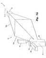
- FIG. 8is an isometric view of yet another aspect of an imaging system
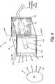
- FIG. 9is a front view of a portion of the imaging system as viewed in the direction of the arrows taken along line A-A of FIG. 8 ;
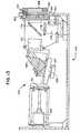
- FIG. 10is a cross-sectional side view taken along line B-B of FIG. 9 and,
- FIG. 11is a block diagram of an imaging system.
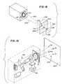
- FIG. 12is a perspective internal view of a third-version of the imaging system of the present invention.
- FIG. 13is an internal view of a fourth version of the imaging system of the present invention with some parts shown in section for purposes of explanation.
- FIG. 14is a diagrammatic view of the fourth version of the imaging system of the present invention.
- FIG. 15is an internal view of a fifth version of the imaging system of the present invention, which uses ambient lighting to illuminate the viewed object.
- FIGS. 16 a and 16 btaken together in sequence, are a program listing for artifact removal image processing of the received image.
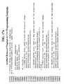
- FIGS. 17 a , 17 b , 17 c , 17 d , 17 e , and 17 ftaken together in sequence, are a program listing in the C++ programming language for artifact removal image processing of the received image.
- FIG. 18is a diagrammatic perspective view showing how a pair of laser pointers are used to position the object to be viewed.
- FIG. 19is a diagrammatic perspective view showing the calibration procedure for the imaging system of the present invention.
- FIGS. 20 a , 20 b , and 20 care photographs of a processed image of subcutaneous blood vessels projected onto body tissue that covers the blood vessels.
- FIG. 21is a photograph of a projected image having a text border therearound.
- FIG. 22is another photograph of a projected image having a text border therearound, similar to FIG. 21 but in which the viewed object has been moved out of position, showing how the text border becomes out-of-focus to indicate that the object is not positioned properly.
- FIG. 23shows a text border image that is combined with a projected image for joint projection onto the object to ensure proper positioning.
- FIG. 24is a photograph of a processed image of subsurface veins projected onto a hand by the present invention, similar to FIG. 20 (which omits the text border) and FIG. 21 but showing how the text border becomes out of focus to indicate that the hand is not positioned properly.
- FIG. 25 a and FIG. 25 bare computer listings showing the solution for bi-linear transformation coefficients of the calibration procedure for the imaging system of the present invention.
- FIG. 26is a program listing in the C++ programming language, which performs the run-time correction to the viewed image of the object using coefficients determined during the calibration procedure.
- Skin and some other body tissuesreflect infrared light in the near-infrared range of about 700 to 900 nanometers, while blood absorbs radiation in this range.
- blood vesselsappear as dark lines against a lighter background of surrounding flesh.
- direct lightthat is, light that arrives generally from a single direction.
- the inventorhas determined that when an area of body tissue having a significant deposit of subcutaneous fat is imaged in near-infrared range under illumination of highly diffuse infrared light, there is significantly higher contrast between the blood vessels and surrounding flesh than when the tissue is viewed under direct infrared illumination.
- the inventionshould not be limited by any particular theory of operation, it appears that most of the diffuse infrared light reflected by the subcutaneous fat is directed away from the viewing direction.
- highly diffuse infrared lightis used to illuminate the tissue, the desired visual contrast between the blood vessels and the surrounding flesh is maintained.
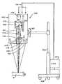
- FIG. 1Shown in FIG. 1 is an imaging system 2 for illuminating an object 32 , such as body tissue, with highly diffuse infrared light, and for producing a video image of the object 32 based upon infrared light reflected from the object 32 .
- an imaging system 2for illuminating an object 32 , such as body tissue, with highly diffuse infrared light, and for producing a video image of the object 32 based upon infrared light reflected from the object 32 .
- an imaging system 2for illuminating an object 32 , such as body tissue, with highly diffuse infrared light, and for producing a video image of the object 32 based upon infrared light reflected from the object 32 .
- the imaging system 2includes an illumination system 10 that illuminates the object 32 with infrared light from multiple different illumination directions.
- the system 10includes multiple infrared light providers 10 a - 10 f , each providing infrared light to the object 32 from a different illumination direction.
- the directions of arrival of the infrared light from each light provider 10 a - 10 fare represented in FIG. 1 by the rays 4 a - 4 f .
- the directions of arrival of the infrared lightranges from perpendicular or near perpendicular to the surface of the object 32 , to parallel or near parallel to the surface of the object 32 . Since the infrared illumination arrives at the object 32 from such a wide range of illumination directions, the infrared illumination is highly diffuse.
- the light providers 10 a - 10 fare preferably light reflecting surfaces that direct light from a single light source toward the object 32 .
- the light providers 10 a - 10 fare individual light sources, or combinations of light sources and reflectors.
- the imaging system 2also includes an imaging device 38 , such as a video camera, for viewing the object 32 .
- the imaging device 38views the object 32 from a viewing direction which is represented in FIG. 1 by the arrow 6 .
- the imaging device 38receives the diffuse infrared light reflected from the object 32 , and generates an electronic video image of the object 32 based on the reflected infrared light.
- FIGS. 2 a and 2 bShown in FIGS. 2 a and 2 b is a preferred embodiment of the illumination system 10 .
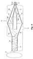
- FIG. 3depicts a cross-sectional view of the system 10 corresponding to the section A-A as shown in FIGS. 2 a - b .
- the system 10preferably includes a light source 12 that emits light into one end of a light diffusing structure 14 .
- the light diffusing structure 14includes an elongate outer enclosure 16 having reflective inner surfaces.
- the inner surfaces of the elongate outer enclosure 16are white in color. Alternatively, these reflective surfaces are mirrored surfaces, or a combination of white and mirrored surfaces.
- a hollow light guide 22At the end of the light diffusing structure 14 opposite the light source 12 , is a hollow light guide 22 .
- the light guide 22serves as an output aperture for the diffuse light.
- the elongate outer enclosure 16includes first and second sections 16 a and 16 b , each having a large end and a small end.
- the first and second sections 16 a and 16 bare substantially pyramidal in shape, each having four trapezoidal faces.
- the four trapezoidal faces of the sections 16 a and 16 bare identical, such that each end of the sections 16 a and 16 b forms a square aperture.
- the larger ends of the first and second sections 16 a and 16 bare joined together to form the enclosure 16 .
- the light source 12is preferably attached to the small end of the first section 16 a at the input aperture 18 .
- the light generated by the light source 12enters the elongate enclosure 16 at the input aperture 18 , and illuminates the interior surfaces of the enclosure 16 .
- an output aperture 20formed by the four short sides of the four trapezoidal faces of the section 16 b .
- Attached at the output aperture 20is one end of the hollow light guide 22 .
- the light guide 22preferably has white reflective inner surfaces similar to the inner surfaces of the enclosure 16 .
- the system 10also includes an elongate inner reflector 24 which is disposed within and preferably coaxial with the outer enclosure 16 .
- the inner reflector 24is shown in FIG. 2 b removed from the outer enclosure 16 .
- the inner reflector 24is formed from a square tubular section 24 a joined to the square base of a pyramidal section 24 b .
- the pyramidal section 24 bhas four sides that taper down to an apex. As shown in FIG. 3 , the apex of the pyramidal section 24 b is disposed proximate the input aperture 18 of the outer enclosure 16 .
- the inner reflector 24has reflective white outer surfaces similar to those of the inner surfaces of the outer enclosure 16 .
- the light diffusing characteristics of the structure 14are best understood with reference to FIG. 3 .
- a lamp 26such as a quartz-halogen bulb and gold-plated reflector manufactured by Gilway and having part number L517A-G. When energized, the lamp 26 produces electromagnetic radiation in the form of white light.
- the lamp 26may be thought of as a point source radiating light in multiple directions, as represented by the exemplary rays 28 and 30 .
- the ray 28reflects from the inner surface of the section 16 b of the outer enclosure 16 .
- the ray 28then travels through the output aperture 20 , into the light guide 22 , and, after multiple reflections from the inner surfaces of the light guide 22 , emits from the exit aperture 23 .
- the ray 30which exits the light source 12 from a different angle than the ray 28 , reflects from the inner reflector 24 .
- the ray 30then reflects from the inner surface of the section 16 b of the outer enclosure 16 , and travels through the output aperture 20 and into the light guide 22 . After multiple reflections from the inner surfaces of the light guide 22 , the ray 30 also emits from the exit aperture 23 , but at a different angle than that of the ray 28 .
- the rays 28 and 30arrive at the object 32 from different angles.
- the light radiating from the light source 12could be represented as an infinite number of rays which strike and reflect from the inner reflector 24 and the inner surfaces of the outer enclosure 16 from an infinite number of angles.
- the light emitted from the exit aperture 23arrives at the object 32 from many different angles, and is therefore highly diffuse light. These arrival angles range from near perpendicular to near parallel with the plane of the exit aperture 23 .
- the diffusing structure 14is three-dimensional, it will be appreciated that light also reflects from the other surfaces of the outer enclosure 16 and the inner reflector 24 , such as those that are perpendicular to the surfaces shown in FIG. 3 . Therefore, the light emitted at the exit aperture 23 of the illumination system 10 is highly diffuse, appearing to be generated by many different light sources.
- the diffusing structure 14efficiently transfers the light radiated from the lamp 26 to the exit aperture 23 .
- a very large fraction of the light provided by the lamp 26reaches the object 32 , and very little light energy is wasted.
- the illumination system 10can be used to provide diffuse light for medical imaging purposes.
- the scope of the inventionis not limited to medical uses.
- the system 10could also be used as a diffuse light source for general photographic purposes.
- the light source 12includes a cold mirror 34 disposed between the lamp 26 and the input aperture 18 of the outer enclosure 16 .
- the cold mirror 34reflects substantially all light having wavelengths outside a selected infrared range of wavelengths.
- the selected rangeincludes wavelengths from approximately 700 to 1000 nanometers.
- an infrared transmitting filter 36which further attenuates light having wavelengths outside the selected infrared range while transmitting light having wavelengths within the selected infrared range.
- the light that passes through the cold mirror 34 and the filter 36 into the outer enclosure 16is infrared light having wavelengths within the selected infrared range.
- the light source 12could be configured to generate infrared light.
- the light source 12could consist of an infrared light-emitting diode (LED) or an array of infrared LEDs.
- LEDinfrared light-emitting diode
- FIG. 3the configuration of the light source 12 shown in FIG. 3 and described above is a preferred embodiment only, and the invention is not limited to any particular configuration of the light source 12 .
- FIG. 4depicts the dimensions of a preferred embodiment of the illumination system 10 .
- the total length of the light diffusing structure 14is approximately 34.82 inches.
- the height and width of the outer enclosure 16 at the juncture of the first and second sections 16 a and 16 bis approximately 10.04 inches.
- the preferred length of the light guide 22is approximately 14.00 inches, and its height and width is approximately 5.08 inches.
- the total length of the inner reflector 24is approximately 15.86 inches.
- the preferred length of the tubular section 24 a of the inner reflector 24is approximately 7.93 inches.
- the height and width of the tubular section 24 ais approximately 3.5 inches.
- the height and width of the light source 12is approximately 2.11 inches.
- a preferred embodiment of the inventionincludes a lens 40 used in conjunction with the video imaging device 38 to produce a video image of the object 32 based on diffuse light reflected from the object 32 .
- the imaging device 38 of this embodimentis a charge-coupled device (CCD) video camera 38 manufactured by Cohu, having model number 631520010000.
- the lens 40 of the preferred embodimentis a 25 mm f-0.95 movie camera lens manufactured by Angenieux.
- the camera 38 and lens 40 of the preferred embodimentare disposed within the tubular section 24 a of the inner reflector 24 .
- the open end of the tubular section 24 aforms an aperture toward which the camera 38 and lens 40 are pointed.
- the hollow light guide 22is substantially centered within the field of view of the camera 38 .
- the camera 38receives light reflected from the object 32 that enters the light guide 22 , travels through the enclosure 16 , and enters the open end of the section 24 a.
- the preferred embodiment of the inventionincludes an infrared-transmitting filter 42 disposed in the open end of the tubular section 24 a .
- This filter 42receives light reflected from the object 32 , and any other light that may enter the enclosure 16 , and substantially eliminates all light having wavelengths outside the infrared range of approximately 700 to 1000 nanometers.
- the filter 42substantially eliminates light having wavelengths outside a selected infrared range of approximately 800 to 850 nanometers.
- the light that passes through the filter 42 and into the lens 40is infrared light within the selected wavelength range. Therefore, the camera 38 primarily receives infrared light which originates from within the illumination system 10 and which is reflected from the object 32 .
- the camera 38Based on the light reflected from the object 32 , the camera 38 generates a video image of the object 32 in the form of an electrical video signal.
- the video signalis preferably provided to an image enhancement board 44 , such as a board manufactured by DigiVision having a model number ICE-3000.
- the board 44generates an enhanced video image signal based on the video signal from the camera 38 .
- the enhanced video image signalis provided to a video capture and display card 46 , such as a model 20-TD Live card manufactured by Miro.
- the card 46captures still images from the image signal which may be saved in digital format on a digital storage device.
- the card 46also formats the video image signal for real-time display on a video monitor 48 .
- the illumination system 10could use other means for generating diffuse infrared light in accordance with the invention.
- the light providers 10 a - 10 f of FIG. 1could be embodied by a ring-light strobe light.
- a circular array of LEDscould be used to illuminate a plastic transmitting diffuser placed near the surface of the object 32 .
- the light providers 10 a - 10 fwould correspond to the individual LEDs in the array.
- the imaging system 2includes a video projector 50 for illuminating the object 32 with an image of the object 32 to enhance the visual contrast between lighter and darker areas of the object 32 .
- a video projector 50for illuminating the object 32 with an image of the object 32 to enhance the visual contrast between lighter and darker areas of the object 32 .
- the features of an objectare visually enhanced for an observer when the features of a projected visible-light image of the object overlay the corresponding features of the object.
- the overlaid visible-light imagecauses the bright features of the object to appear brighter while the dark areas remain the same.
- FIGS. 6 a and 6 bThe embodiment of the invention shown in FIGS. 6 a and 6 b provides diffuse infrared light (represented by the rays 52 ) to the object 32 in a manner similar to that described previously. However, in the embodiment shown in FIGS. 6 a and 6 b , the optical path of the illuminating light is folded, such that the exit aperture 23 of the light guide 22 is rotated by 90 degrees relative to the exit aperture shown in FIGS. 1-3 .
- a beam separatorsuch as a hot mirror 54 receives infrared light 52 from the interior of the light diffusing structure 14 and reflects the infrared light 52 into the light guide 22 and toward the object 32 .
- the hot mirror 54also receives an infrared image of the object 32 (represented by the ray 56 ) and reflects it toward the camera 38 .
- the hot mirror 54receives the visible-light image (represented by the ray 58 ) from the projector 50 and transmits it into the light guide 22 and toward the object 32 .
- the video output signal from the video camera 38is provided as a video input signal to the projector 50 .
- the projector 50projects the visible-light image 58 of the object 32 toward the hot mirror 54 .
- the hot mirror 54receives the visible-light image 58 and transmits it into the light guide 22 toward the object 32 .
- the features in the projected visible-light image 58are made to overlay the corresponding features of the object 32 .
- the object 32is body tissue
- the inventionis used to find subcutaneous blood vessels in the body tissue
- the blood vesselsappear as dark lines in the projected visible-light image 58 .
- the visible-light image 58is projected onto the body tissue
- the subcutaneous blood vesselswill lie directly beneath the dark lines in the projected visible-light image 58 .
- the inventionsignificantly improves a medical practitioner's ability to find subcutaneous blood vessels while minimizing discomfort for the patient.
- FIGS. 7 a and 7 bdepict an alternative embodiment of the invention for use as a contrast enhancing illuminator.
- the embodiment of FIGS. 7 a - boperates in a fashion similar to the embodiment of FIGS. 6 a and 6 b .
- the camera 38is located outside the light diffusing structure 14 .
- the hot mirror 54 shown in FIGS. 7 a - bis rotated by 90 degrees clockwise relative to its position in FIGS. 6 a - b . Otherwise, the hot mirror 54 serves a similar function as that described above in reference to FIGS. 6 a - b .
- the infrared-transmitting filter 42is mounted in a wall of the light guide 22 .
- a reflective panel 60is provided in this embodiment to further direct the light from the light source 12 into the light guide 22 and toward the exit aperture 23 .
- the panel 60is a flat reflective sheet having an orifice therein to allow light to pass between the object 32 and the camera 38 and projector 50 .
- FIGS. 8-11A preferred embodiment of a relatively compact and highly reliable imaging system 70 is depicted in FIGS. 8-11 .
- the imaging system 70is most preferably configured to illuminate an object 71 , such as body tissue and the like, and to produce a video image of the object 71 based upon infrared light reflected from the object 71 .
- the imaging system 70preferably includes a housing 72 which contains the imaging features of the system 70 .
- the housing 72preferably has a substantially rectangular configuration.
- the housing 72preferably has a length of between about three and about five inches and a width of about three and one-half inches.
- the imaging system 70can be configured in a variety of ways and the invention should not be limited by any specific examples or embodiments discussed herein.
- the housingis depicted as being substantially rectangular, however, circular, polygonal, and other geometries and sizes are feasible as well.
- An imaging device 74such as a video camera having a lens 75 , and video processing components reside within the housing 72 .
- the imaging device 74 and video processing componentsoperate to detect infrared light and to process the detected infrared light from the object 71 .
- the imaging system 74produces an image based on the detected infrared light reflected from the object 71 , as described herein.
- the imaging device 74is preferably mounted within an aperture 76 of mounting wall 78 , with the lens 75 extending into the housing interior 77 , as described further below. More particularly, the camera 74 is preferably centrally and symmetrically mounted within the housing 72 . This preferred symmetrical camera location tends to maximize the amount of light detected by the camera, which enhances the image produced by the system 70 , thereby enhancing the illumination of blood vessels disposed below subcutaneous fat in body tissue.
- the housing 72most preferably contains various components operable to transmit diffuse light from the system 70 toward the object 71 .
- Arrows 80represent diffuse light transmitted by the system 70 .
- Arrows 82represent the light reflected from the object 71 .
- the wall 78contains a number of infrared light emitting diodes (LEDs) 84 disposed in a LED array 85 for emitting infrared light.
- the LED array 85defines a LED plane of reference.
- each LED 84When activated, each LED 84 preferably transmits light at a wavelength of about 740 nanometers (nm). In the preferred embodiment, each LED 84 is manufactured by Roithner Lasertechnik of Austria under model number ELD-740-524.
- the LEDs 84are mounted on a circuit board 86 located adjacent to wall 78 .
- the concentric LED arrangementtends to provide maximal dispersion and transmission of diffuse light from the system 70 .
- each group 92 , 94 of LEDs 84contain at least ten LEDs 84 .
- the system 70can include more or fewer LEDs within a particular group depending upon a desired implementation of the system 70 .
- the system 70can include more or fewer groups of LEDs in the LED array 85 .
- each group 92 of LEDs 84located about the corner regions 96 of the LED array 85 . Most preferably, at least fifteen LEDs 84 are disposed in each corner region 96 of the LED array 85 . There are preferably four groups 94 of LEDs 84 disposed in lateral regions 98 of the LED array 85 . Each lateral region 98 is located substantially between each corner region 94 . Most preferably, at least ten LEDs 84 are disposed in each lateral region 98 of the LED array 85 .
- the LED array 85is most preferably disposed on circuit board 86 .
- the circuit board 86includes control circuitry that controls the activation of one or more LEDs 84 within a particular group or groups 92 , 94 of LEDs 84 in the LED array 85 .
- a power source 88 and a control system 90are electrically connected to the circuit board 86 . It will be appreciated that is also possible to control the LEDs without using a control system 90 , that is, power source 88 can be switched “on” or “off” to activate and deactivate the LED array 85 .
- pulse modulation techniquescan also be used in conjunction with power source 88 to activate and deactivate one or more of the LEDs 84 in the LED array 85 according to a preferred duty cycle, herein defined as the LED “on” time relative to the LED “off” time.
- the LED array 85is electrically connected via circuit board 86 to the power source 88 and control system 90 .
- the control system 90includes control features for controlling the LED array 85 to emit infrared light toward an object 71 .
- the control system 90can enable one or more of the LEDs 84 in a group or groups of the LED array 85 to emit light continuously or intermittently. That is, one LED 84 or a plurality of LEDs 84 can be selected and controlled to emit infrared light intermittently or continuously toward the object 71 .
- the system 70can be configured to transmit infrared light from the LED array in various permutations and combinations of LEDs 84 and/or LED groups 92 , 94 .
- a first diffusion layer 100is disposed adjacent to the emitting surfaces 102 of the LEDs 84 in the LED array 85 .
- the first diffusion layer 100is glued, such as using known adhesives, onto the emitting surfaces 102 of the LED array 85 , thereby operating to diffuse the light emitted by one or more LEDs 84 in the LED array 85 .
- the first diffusion layer 100is most preferably a holographic twenty degree diffuser, such as a product having identification code LSD20PC10-F10 ⁇ 10/PSA, manufactured by Physical Optics Corporation of Torrance, Calif.
- the first diffusion layer 100has a length of about three and one-half inches, a width of about three and one-half inches, and a thickness of about 0.10 inches.
- the first diffusion layer 100diffuses the infrared light emitted from the LED array 85 , thereby providing a first amount of diffusion to the emitted infrared light.
- the interior surfaces 104 of the housing 72are shown in FIG. 10 .
- the interior surfaces 104are coated with a reflective coating, such as white paint or the like, which reflects and further diffuses the already diffuse light produced by the first diffusion layer 100 .
- a second diffusion layer 106is spaced apart from the first diffusion layer 100 by a distance LDD.
- the distance LDD between the first and second diffusion layers 100 and 106is about three inches.
- the second diffusion layer 106is most preferably a holographic twenty degree diffuser, similar to or the same as the above-described first diffusion layer 100 .
- the second diffusion layer 106has a preferred length of about three and one-half inches, a width of about three and one-half inches, and a thickness of about 0.10 inches.
- the second diffusion layer 106further diffuses the already diffuse light reflected from the interior surfaces 104 and provided by the first diffusion layer 100 .
- the first and second diffusion layersare substantially planar, that is, the layers 100 and 106 each define a planar geometry. According to the most preferred embodiment, the planes defined by the first and second diffusion layers 100 and 106 are substantially parallel with respect to one another. The preferred parallel planar arrangement of the diffusion layers 100 , 106 tends to promote a quantifiable and uniform amount of diffuse light emanating from the system 70 when one or more of the LEDs 84 are enabled.
- a backing material 108such as LUCITE material sold under the trademark LUCITE and manufactured by DuPont of Wilmington, Del., is disposed adjacent to the second diffusion layer 106 . Most preferably, the backing material has a thickness of about 0.125 inches.
- a visible polarizer 110is disposed adjacent to the backing material 108 . The visible polarizer 110 is most preferably manufactured by Visual Pursuits of Vernon Hills, Ill., under part number VP-GS-12U, and having a thickness of about 0.075 inches.
- the system 70is operable to produce various levels of diffusion as the emitted light progresses through the first diffusion layer 100 , reflects off of the interior surfaces 104 of the first compartment 72 a , and continues to progress through the second diffusion layer 106 , backing material 108 , and polarizer 110 .
- a level of diffusionresults after the emitted light passes through the first diffusion layer 100 .
- Another level of diffusionresults from the reflection from the interior surfaces 104 of the first compartment 72 a of the already diffused light provided by the first diffusion layer 100 .
- Yet another level of diffusionresults after the diffuse light passes through the second diffusion layer 106 .
- the visible polarizer 110preferably includes a central portion 112 , most preferably in the shape of a circle having about a one-inch diameter.
- the central portion 112 geometrymost preferably coincides with the shape and dimension of the camera lens 75 .
- the polarization of the central portion 112is preferably rotated approximately ninety degrees with respect to the polarization of the surrounding area 114 of the polarizer 110 .
- the camera lens 75contacts the backing material 108 .
- the positional location of the lens 75 within the housing 70preferably coincides with or shares the same central axis as the central portion 112 of the polarizer 110 .
- the central portion 112 of the polarizer 110 coinciding with the front of the lens 75tends to remove any surface glare (“specular reflection”) in the resulting camera image.
- the backing material 108 and the visible polarizer 110have planar surfaces which preferably include a similar planar orientation with respect to the planes defined by the first and second diffusion layers 100 , 106 .
- the first diffusion layer 100 , interior surfaces 104 , second diffusion layer 106 , backing material 108 , and visible polarizer 110define a diffusing system 116 ( FIG. 10 ) for providing diffuse light to an object 71 .
- the diffusing structurecan include more or fewer components and the invention is not to be limited by any specific examples or embodiments disclosed herein.
- the diffusing system 116can include either the first or the second diffusion layers 100 , 106 , with or without the polarizer 110 , or can include the first and second diffusion layers 100 , 106 without the polarizer 110 .
- the system 70operates to transmit diffuse light 80 toward an object 71 and produce a video image of the object 71 with the imaging system 74 , as described above. More particularly, once the power source 88 is enabled, one or more of the LEDs 84 in the LED array 85 emit infrared light from the emitting surface(s) 102 .
- the first diffusion layer 100provides a first amount of diffusion to the emitted infrared light.
- the interior surfaces 104further diffuse the diffuse light emanating from the first diffusion layer 100 .
- the second diffusion layer 106further diffuses the already diffuse light which is then transmitted through the backing material 108 and the polarizer before illuminating the object 71 .
- the object 71reflects the emitted diffuse light 80 producing diffuse reflected light 82 that is captured by the imaging system 74 .
- the imaging system 74then produces a video image of the object 71 . Accordingly, by emitting diffuse light according to a unique diffusion providing system 70 , the system 70 aids in locating and differentiating between different material properties of the object 71 , such as between blood vessels and tissue.
- the planes defined by the first or second diffusing layers 100 and 106can be adjusted to not be parallel with respect to one another, thereby providing different levels of diffuse light from the system 70 .
- the plane defined by the LED array 85is most preferably in substantial parallel relation with respect to the plane defined by the first diffusing layer 100 .
- the planes defined by LED array 85 and the first diffusing layer 100can be varied to accommodate various operational conditions, as will be appreciated by those skilled in the art. Accordingly, it is expressly intended that the foregoing description and the accompanying drawings are illustrative of preferred embodiments only, not limiting thereto, and that the true spirit and scope of the present invention be determined by reference to the appended claims.
- FIGS. 20 a , 20 b , and 20 care photographs of test subjects showing processed images of subcutaneous blood vessels being projected onto the surface of each subject's body tissue which covers the viewed blood vessels.
- an observer using the present inventionis not subject to the parallax errors that otherwise occur with prior art devices if an observer were to view from off-axis.
- An important feature of all embodimentsis that the image of buried structure viewed by the imaging device should be substantially within a first spectrum outside a second spectrum of the image that is projected back onto the surface of the object, thereby causing the imaging device to be blind to the image that is projected back onto the surface of the object.
- the substantial non-overlap of the spectrum of the viewed image of the buried structure with the spectrum of the projected image of the buried structureeffectively decouples the image processing of the buried structure's image from interference by the projected image. Because the projected image is in the visible light spectrum and the illumination of the object for the imaging device is in the infrared spectrum, a substantial non-overlap of the two spectrums is maintained.
- the objectcan be illuminated by broad-spectrum ambient light, and an infrared filter is placed in front of the imaging device to remove all spectral components outside the infrared spectrum, thereby causing the imaging device to only see the infrared component of the broad-spectrum diffuse light reflected from the object.
- a third preferred embodiment 130 of the imaging systemis shown in FIG. 12 .
- the near-infrared illuminationA well-known CCD camera with lens 132 is used as the imaging device, as in all embodiments.
- a second polarizing filter 134is interposed between the CCD camera and the reflected light from the viewed object, as previously described for earlier embodiments, so as to reduce specular reflection from the surface of the object.
- the illumination source, first polarizing filter, holographic illumination diffuser ring, and optically-neutral glass cover, all generally at 136are best described below in the discussion of the fourth embodiment of the imaging system shown in FIGS. 13 and 14 , which has the same structure 136 which is shown in cross-section for that embodiment.
- the third preferred embodimentincludes a well-known video projector 138 or so-called “light engine” for projecting a visible image onto the object O under examination.
- a desirable feature of the video projector 138is high output light intensity, because the intensity of the output of the projector's light is a determining factor in how well the projected image can be viewed under normal room illumination.
- Video projector 138includes a high-intensity green LED light source 140 which emits light into well-known prism assembly 142 , thereby causing the emitted light to fold back, by internal reflection within prism assembly 142 , and be directed rearwardly toward well-known Digital Light Processing (“DLP”) device 144 , also known as a Digital Mirror Device (“DMD”), having an array of closely-packed small mirrors that can individually shift the direction of the light beam reflected therefrom so as to either cause the light beam to be directed toward the target object through well-known projection lens 146 or to cause the light beam to not be directed toward the target object, thereby turning the emitted light beam off on a pixel-by-pixel basis in a manner well-known to those skilled in the art.
- DLPDigital Light Processing
- DMDDigital Mirror Device
- prism assembly 142permits a more compact apparatus for the various embodiments of the imaging system, and the use of such prism assemblies is well known to those skilled in the art of video projectors.
- a well-known so-called “hot mirror” 148is interposed at 45 degrees to intercept the infrared light reflected from the viewed object and reflect that infrared light downward to camera 132 .
- “Hot mirror” 148acts as a mirror to longer wavelengths of light (such as infrared light) but higher-frequency light, such as the green light from projector 138 , passes through without reflection and toward the viewed object.
- Imaging system 130further has first and second lasers 150 , 152 for ensuring that the target is properly located for in-focus viewing by camera 132 , as hereinafter described.
- FIGS. 13 and 14a fourth embodiment 154 of the imaging system of the present invention will now be explained.
- Fourth embodiment 154is mounted upon a pole 156 that extends upwardly from a mobile cart 158 , allowing the imaging system 154 to be easily transported.
- a fine-focus stage 160allows imaging system 154 to be raised or lowered so that it is properly positioned above the target object O.
- video projector 162is provided with a 525 nm green LED illumination source (“photon engine”) 164 for illuminating the DMD/DLP chip 166 .
- a suitable photon engine 164 for use with the fourth embodimentis the Teledyne Lighting model PE09-G illuminator, having an output intensity of 85 lumens.
- DMD chip 166may be a Texas Instruments part number 0.7SVGA SDR DMD chip having a resolution of 848 ⁇ 600 pixels and a mirror tilt angle of ten degrees and a frame rate of 30 Hz.
- Well-known prism assembly 168internally reflects the light from photon engine 164 toward DMD chip 166 and then directs the light reflected from DMD chip 166 toward object O.
- DMD chip 166is controlled by a well-known drive electronics board 167 which may be made by Optical Sciences Corporation.
- a condenser lens 170such as a BK7 Bioconvex lens, part number 013-2790-A55, sold by OptoSigma, having a BBAR/AR coated surface coating for 425-675 nm light.
- a condenser lens 170such as a BK7 Bioconvex lens, part number 013-2790-A55, sold by OptoSigma, having a BBAR/AR coated surface coating for 425-675 nm light.
- the projector lightemerges from prism assembly 168 , it passes through well-known projection lens 172 , Besler part number 8680 medium format enlarger lens and then through well-known “hot-mirror” (high pass filter) 174 , which reflects the received infrared light image from the object O through second polarizing filter 178 ant then to camera 176 .
- a suitable camera 176is the Firefly Camera, part number FIRE-BW-XX, sold by Point Grey Research, which uses a 640 ⁇ 480 CCD chip, part number Sony ICX084AL, and which communicates its images to computer (“CPU”) 180 through an IEEE-1394 (“FireWire”) interface.
- computer 180has a number of interfaces signals 181 that communicate with the imaging system in a manner well-known to those skilled in the art.
- the fourth embodimentalso has first and second lasers 150 , 152 for ensuring that the target O is properly located for in-focus viewing by camera 176 .
- fourth embodiment 154has an assembly 136 that includes infrared illumination source 182 , first polarizing filter 184 (which is ring-shaped with a center hole therethrough so as not to affect the projected image from projector 162 or the viewed image of the object), holographic illumination diffuser ring 186 (which likewise has a center hole therethrough for passage of the projected image from projector 162 and of the viewed image of the object) and which diffuses the light from LEDs 190 , and optically-neutral glass cover 188 .
- first polarizing filter 184which is ring-shaped with a center hole therethrough so as not to affect the projected image from projector 162 or the viewed image of the object
- holographic illumination diffuser ring 186which likewise has a center hole therethrough for passage of the projected image from projector 162 and of the viewed image of the object and which diffuses the light from LEDs 190 , and optically-neutral glass cover 188 .
- Infrared illumination source 182is a group of LEDs preferably arranged in a select pattern, such as a circular ring having a centrally-disposed hole through which the projected image and the viewed object's image passes.
- the LEDsare preferably 740 nm near-infrared LEDs 190 that illuminate the object O, and research has determined that such a structure provides sufficient diffused infrared light for satisfactory illumination of object O.
- a fifth embodiment 192 of the imaging system of the present inventionwill now be explained.
- the fifth embodimentdoes not provide an integral diffuse infrared light source (e.g., illumination source 182 with a ring of LEDs 190 ) for illuminating the object, but instead views the object as illuminated by ambient light L (or the sun S) that has a broader spectrum than the integral diffuse infrared illumination sources heretofore disclosed.
- ambient lighthas some infrared spectral components and is quite diffuse, those infrared spectral components are generally of lower intensity than the infrared light produced by the diffuse infrared illumination sources heretofore disclosed. Accordingly, a better (i.e., more sensitive) image device camera is required for this embodiment, with better optics than the previously-described embodiments.
- the fifth embodiment 192includes video projector 162 , including a green “photon engine” 164 , prism assembly 168 , projector lens 172 , and DMD chip 166 .
- video projector 162including a green “photon engine” 164 , prism assembly 168 , projector lens 172 , and DMD chip 166 .
- fifth embodiment 192includes a “fold mirror” 194 that folds the beam at a right angle within the projector between the photon engine 164 and prism assembly 168 .
- fifth embodiment 192includes a “hot mirror” 174 .
- Fifth embodiment 192further has an infrared filter 196 interposed in the optical path between the imaging device (camera 198 ) and object O so as to filter out all but the infrared component of the image viewed by camera 198 .
- Camera 198is preferably a Basler CMOS camera, model A600-HDR, made by Basler Vision Technologies of Germany, which has an IEEE 1394 (“FireWire”) interface and allows capture of images with up to a 112 dB dynamic range.
- An advantage of the fifth embodimentis that it can be (and should be) used in a brightly-illuminated room.
- FIGS. 16 a and 16 btaken together in sequence, are a program listing for artifact removal image processing of the received image.
- the same artifact removal procedureis performed twice, and then a well-known adaptive edge enhancement procedure is performed, such as, for example, unsharp masking, followed by a smoothing to clean up image artifacts produced by the hair removal.
- a well-known adaptive edge enhancement procedureis performed, such as, for example, unsharp masking, followed by a smoothing to clean up image artifacts produced by the hair removal.
- the program listingis well-commented and explains to those skilled in the art the image processing steps that are applied to the image.
- the received imagehaving integer pixel values in the range (0 . . . 255) is converted to floating point values between 0.0 and 1.0, inclusive.
- the resulting imageis then converted to smoothed (blurred) using a Gaussian convolution having a sigma of 8 pixels. This is a fairly small value of sigma, and leave small features, such as narrow hairs, in the resulting smoothed image.
- a “difference image”is created which is the original image minus the Gaussian-smoothed image, producing a zero-centered set of values from ⁇ 1.0 to 1.0.
- the original image (“im1”)having pixel values ranging from 0.0 to 1.0, is then “boosted” at every “hair pixel” location by 0.015. Because this is a highly non-linear operation, the amount of “boost” if quite small, just 1.5%.
- This same set of operations(Gaussian smoothing with a sigma of 8 pixels, creation of a difference image, identifying negative pixel locations, and “boosting” the image where negative pixels (small features and noise) are found) are performed again, and the resulting image is then smoothed again with a Gaussian convolution having a sigma of 64 pixels.
- a third difference imageis created, which is the again-“boosted” image minus the smoothed image, and an image is created that is formed from the absolute value of every pixel in the third difference image.
- the resulting absolute value imageis then smoothed with a Gaussian convolution having a sigma of 64 pixels, and the third difference image is then divided by the smoothed absolute value image, and the resulting divided image is smoothed with a Gaussian convolution having a sigma of 4 pixels.
- the foregoing Artifact Removal algorithmallows the contrast to be set by the contrast of the subcutaneous vein (the subsurface structure of interest), ignoring the artifacts (hairs), and thereby prepares the image for adaptive unsharp masking edge enhancement to set the contrast of the final image.
- Parameterssuch as sigma values, thresholds, etc., may be varied depending on the age of the subject, degree of pigmentation, etc.
- FIGS. 17 a , 17 b , 17 c , 17 d , 17 e , and 17 ftaken together in sequence, are a program listing in the C++ programming language for artifact removal image processing of the received image which is based upon the research/investigation program shown in FIG. 16 a and FIG. 16 b , but instead uses the Intel image processing library to perform the mathematical operations more quickly.
- any or all of the embodiments of the present inventionpreferably include a mechanism for keeping the image of the buried structure, as seen by the imaging device, in focus to the image device camera with a proper lens-to-subject distance thereto.
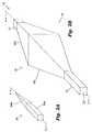
- a first embodiment of this mechanismuses a pair of lasers, 150 , 152 , each laser respectively emitting a beam 200 , 202 , with beams 200 and 202 being non-parallel with respect to each other and thus being directed toward the object from different angles, such that the two laser beams only converge to the same spot 204 and intersect when the target is at the proper lens-to-subject distance from the imaging device, as shown by the position of intersecting plane 206 .
- the two laser beamswill not intersect at a single point 204 but instead will appear on the surface of the object as a first pair of visible dots 212 , 214 (for plane 208 ) or as a second pair of visible dots 216 , 218 (for plane 210 ), indicating that the buried structure is not in focus to the imaging device camera, and that the distance from the object to the apparatus should be changed to bring the viewed image of the buried structure into focus.
- Lasers 150 and 152may also be seen in FIGS. 12 , 13 , and 14 . Suitable lasers for use with the present invention are the model LM-03 laser modules made by Roithner Lasertechnik, of Vienna, Austria.
- a second embodiment of the target positioning mechanismadds a recognizable visible light pattern, such as a text border, independent of the buried structure being observed, to the projected image for mutual projection therewith.
- the projected recognizable patternwill only be recognized by the human viewer as being in focus on the surface of the target object when the target is at the desired distance from the projector, thereby causing the buried structure beneath the surface of the target to also be at the proper lens-to-subject distance from the imaging device.
- cartoon figures appealing to childrencould be provided as an incentive for children to properly position their body parts for viewing subcutaneous blood vessels, or a hospital's or clinic's logo or name could be used for the pattern.
- the photograph of FIG. 21shows a projected image having a text border therearound.
- FIG. 22is another photograph of a projected image having a text border therearound, similar to FIG. 21 but in which the viewed object has been moved out of position, showing how the text border becomes out-of-focus to indicate that the object is not positioned properly with respect to the image device camera.
- FIG. 23shows a text border image that is combined with a projected image for joint projection onto the object to ensure proper positioning. Because of the image reversal that occurs in some embodiments of the invention as images reflect inside the prism structure heretofore described, this text border image is shown reversed but appears unreversed when projected. The projected image is appropriately cropped before combining with the text border so that the text border remains sharp and distinct when projected.
- FIG. 24is a photograph of a processed image of subsurface veins projected onto a hand by the present invention, similar to FIG. 20 (which omits the text border) and FIG. 21 but showing how the text border becomes out of focus to indicate that the hand is not positioned properly.
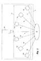
- a calibration methodis provided wherein the video projector 138 (or 162 , or any of the projector of the present invention) projects a green target pattern 220 onto a fluorescent screen 222 , which converts the projected four-dot green target pattern 220 into deep red light that is visible by the infrared imaging device 132 .
- a computer programrecords the observed position of the viewed pattern of four projected dots P 1 , P 2 , P 3 , and P 4 , in Cartesian coordinates, i.e., (x1, y1), (x2, y2), (x3, y3), and (x4, y4), versus the desired or “true” position of the dots if alignment were correct, i.e., (X1, Y1), (X2, Y2), (X3, Y3), and (X4, Y4), and calculates calibration coefficients (a, b, c, d, g, h, k, f) to be used in the bi-linear transformation equations (the arguments to the “solve” function in FIG. 25 a and FIG.
- FIG. 25 a and FIG. 25 bshow the use of the MAPLE 9 computer equation solving program to solve for the bilinear transformation coefficients as a function of the values measured during calibration. These calibration coefficients are used during operation of the device to transform the coordinate system of the image (x, y) into the corrected coordinate system (X, Y) necessary to produce a calibrated image.
- FIG. 26shows how these coordinates, once calculated during calibration, are used as parameters to a well-known image processing library mathematical routine provided by the integrated circuit company Intel for use with its processors, to achieve high performance image alignment correction using the bilinear transformation equation. The run-time calculations are done using scaled integer arithmetic, rather than floating point arithmetic, for faster processing of the image.
- the calibration procedureprojects a test pattern 220 , consisting of four dots P 1 , P 2 , P 3 , and P 4 , each having a 25-pixel radius (as viewed by the imaging device camera) at the corners of a rectangle having dimensions of 320 ⁇ 240 pixels rectangle (as viewed by the imaging device camera), onto the fluorescent.
- the camera 132might have a resolution of 640 ⁇ 480 pixels
- the projector 138might have a resolution of 1024 ⁇ 780 pixels.
- Experimental testing for dot radii varying from 4 to 50 pixelsshowed that the standard deviation of 100 samples decreased rapidly from a dot radius of 5 pixels to about 25 pixels, and then decreased much more slowly out to a radius of 50 pixels.
- a test pattern of four spaced-apart dots P 1 , P 2 , P 3 , and P 4is projected within a first spectrum, preferably using green light, onto a fluorescent screen 222 , which then fluoresces and produces light within a second spectrum, preferably light adjacent or within the infrared spectrum, such as red light, that is visible to the image device camera 132 , even through the infrared transmitting filter through which the image device camera views its target object.
- Calibration softwarethen measures the observed position of the four dots and computes the correction coefficients (a, b, c, d, g, f, h, k) for the bi-linear transformation equation, and then uses those coefficients as parameters to the bi-linear transformation in order to correct misalignment errors (rotation, translation, and magnification) between the image device camera and the projector by warping the image prior to projection so that the projected image is corrected for misalignment.
- misalignment errorsrotation, translation, and magnification
- any embodimentcould choose to illuminate the object using infrared components within ambient lighting, rather than providing a separate diffuse infrared light source, and/or could choose between a laser target positioner and a recognizable pattern that is combined with the projected image of the buried structure for maintaining a desired distance from the image device camera to the object.
Landscapes
- Health & Medical Sciences (AREA)
- Life Sciences & Earth Sciences (AREA)
- Engineering & Computer Science (AREA)
- Surgery (AREA)
- Medical Informatics (AREA)
- Animal Behavior & Ethology (AREA)
- Veterinary Medicine (AREA)
- Pathology (AREA)
- Biomedical Technology (AREA)
- Heart & Thoracic Surgery (AREA)
- Public Health (AREA)
- Molecular Biology (AREA)
- General Health & Medical Sciences (AREA)
- Physics & Mathematics (AREA)
- Multimedia (AREA)
- Signal Processing (AREA)
- Biophysics (AREA)
- Vascular Medicine (AREA)
- Nuclear Medicine, Radiotherapy & Molecular Imaging (AREA)
- Oral & Maxillofacial Surgery (AREA)
- Investigating Or Analysing Materials By Optical Means (AREA)
- Studio Devices (AREA)
Abstract
Description
Claims (6)
Priority Applications (1)
| Application Number | Priority Date | Filing Date | Title |
|---|---|---|---|
| US11/173,452US8078263B2 (en) | 2000-01-19 | 2005-07-01 | Projection of subsurface structure onto an object's surface |
Applications Claiming Priority (3)
| Application Number | Priority Date | Filing Date | Title |
|---|---|---|---|
| US09/487,007US6556858B1 (en) | 2000-01-19 | 2000-01-19 | Diffuse infrared light imaging system |
| US10/386,249US7239909B2 (en) | 2000-01-19 | 2003-03-11 | Imaging system using diffuse infrared light |
| US11/173,452US8078263B2 (en) | 2000-01-19 | 2005-07-01 | Projection of subsurface structure onto an object's surface |
Related Parent Applications (1)
| Application Number | Title | Priority Date | Filing Date |
|---|---|---|---|
| US10/386,249Continuation-In-PartUS7239909B2 (en) | 2000-01-19 | 2003-03-11 | Imaging system using diffuse infrared light |
Publications (2)
| Publication Number | Publication Date |
|---|---|
| US20060122515A1 US20060122515A1 (en) | 2006-06-08 |
| US8078263B2true US8078263B2 (en) | 2011-12-13 |
Family
ID=46322211
Family Applications (1)
| Application Number | Title | Priority Date | Filing Date |
|---|---|---|---|
| US11/173,452Expired - Fee RelatedUS8078263B2 (en) | 2000-01-19 | 2005-07-01 | Projection of subsurface structure onto an object's surface |
Country Status (1)
| Country | Link |
|---|---|
| US (1) | US8078263B2 (en) |
Cited By (34)
| Publication number | Priority date | Publication date | Assignee | Title |
|---|---|---|---|---|
| US20090002488A1 (en)* | 2007-06-28 | 2009-01-01 | Vincent Luciano | Automatic alignment of a contrast enhancement system |
| US20110021925A1 (en)* | 2006-06-29 | 2011-01-27 | Fred Wood | Mounted vein contrast enchancer |
| US20110054327A1 (en)* | 2008-04-11 | 2011-03-03 | Seong Keun Kim | Hypodermic Vein Detection Imaging Apparatus based on Infrared Optical System |
| US8551150B1 (en) | 2007-01-11 | 2013-10-08 | Lockheed Martin Corporation | Method and system for optical stimulation of nerves |
| US20140015953A1 (en)* | 2011-01-12 | 2014-01-16 | Idea Machine Development Design & Production Ltd. | Compact microscopy system and method |
| US8632577B1 (en) | 2007-01-19 | 2014-01-21 | Lockheed Martin Corporation | Hybrid optical-electrical probes for stimulation of nerve or other animal tissue |
| US8747447B2 (en) | 2011-07-22 | 2014-06-10 | Lockheed Martin Corporation | Cochlear implant and method enabling enhanced music perception |
| US8838210B2 (en) | 2006-06-29 | 2014-09-16 | AccuView, Inc. | Scanned laser vein contrast enhancer using a single laser |
| US20150029321A1 (en)* | 2013-01-21 | 2015-01-29 | Panasonic Corporation | Measuring system and measuring method |
| US8945197B1 (en) | 2005-10-24 | 2015-02-03 | Lockheed Martin Corporation | Sight-restoring visual prosthetic and method using infrared nerve-stimulation light |
| US8956396B1 (en) | 2005-10-24 | 2015-02-17 | Lockheed Martin Corporation | Eye-tracking visual prosthetic and method |
| US8985119B1 (en) | 2005-09-09 | 2015-03-24 | Lockheed Martin Corporation | Method and apparatus for optical stimulation of nerves and other animal tissue |
| US9042967B2 (en) | 2008-05-20 | 2015-05-26 | University Health Network | Device and method for wound imaging and monitoring |
| US9042966B2 (en) | 2006-01-10 | 2015-05-26 | Accuvein, Inc. | Three dimensional imaging of veins |
| US9061109B2 (en) | 2009-07-22 | 2015-06-23 | Accuvein, Inc. | Vein scanner with user interface |
| US9072426B2 (en) | 2012-08-02 | 2015-07-07 | AccuVein, Inc | Device for detecting and illuminating vasculature using an FPGA |
| US9345427B2 (en) | 2006-06-29 | 2016-05-24 | Accuvein, Inc. | Method of using a combination vein contrast enhancer and bar code scanning device |
| US9492117B2 (en) | 2006-01-10 | 2016-11-15 | Accuvein, Inc. | Practitioner-mounted micro vein enhancer |
| US9854977B2 (en) | 2006-01-10 | 2018-01-02 | Accuvein, Inc. | Scanned laser vein contrast enhancer using a single laser, and modulation circuitry |
| US10061349B2 (en) | 2012-12-06 | 2018-08-28 | Sandisk Technologies Llc | Head mountable camera system |
| US10110805B2 (en) | 2012-12-06 | 2018-10-23 | Sandisk Technologies Llc | Head mountable camera system |
| US10238294B2 (en) | 2006-06-29 | 2019-03-26 | Accuvein, Inc. | Scanned laser vein contrast enhancer using one laser |
| US10376148B2 (en) | 2012-12-05 | 2019-08-13 | Accuvein, Inc. | System and method for laser imaging and ablation of cancer cells using fluorescence |
| US10438356B2 (en) | 2014-07-24 | 2019-10-08 | University Health Network | Collection and analysis of data for diagnostic purposes |
| US10813588B2 (en) | 2006-01-10 | 2020-10-27 | Accuvein, Inc. | Micro vein enhancer |
| US11051697B2 (en) | 2006-06-29 | 2021-07-06 | Accuvein, Inc. | Multispectral detection and presentation of an object's characteristics |
| US11253198B2 (en) | 2006-01-10 | 2022-02-22 | Accuvein, Inc. | Stand-mounted scanned laser vein contrast enhancer |
| US11278240B2 (en) | 2006-01-10 | 2022-03-22 | Accuvein, Inc. | Trigger-actuated laser vein contrast enhancer |
| US11553863B2 (en) | 2019-08-01 | 2023-01-17 | Industrial Technology Research Institute | Venous positioning projector |
| USD999379S1 (en) | 2010-07-22 | 2023-09-19 | Accuvein, Inc. | Vein imager and cradle in combination |
| US12048560B2 (en) | 2006-01-10 | 2024-07-30 | Accuvein, Inc. | Vein scanner configured for single-handed lifting and use |
| US12295744B2 (en) | 2006-01-10 | 2025-05-13 | Accuvein, Inc. | Micro vein enhancer with two lasers and two optical detectors configured for removing surface topology |
| US12303324B2 (en) | 2018-05-31 | 2025-05-20 | Faction Imaging Inc. | Method of medical imaging using multiple arrays |
| US12408865B2 (en) | 2006-01-10 | 2025-09-09 | Accuvein Inc. | Vein imaging device with differential image resolution at the center and the extremities of the vein image |
Families Citing this family (40)
| Publication number | Priority date | Publication date | Assignee | Title |
|---|---|---|---|---|
| US8078263B2 (en) | 2000-01-19 | 2011-12-13 | Christie Medical Holdings, Inc. | Projection of subsurface structure onto an object's surface |
| US20070161906A1 (en)* | 2000-01-19 | 2007-07-12 | Luminetx Technologies Corporation | Method To Facilitate A Dermatological Procedure |
| US8494616B2 (en) | 2000-01-19 | 2013-07-23 | Christie Medical Holdings, Inc. | Method and apparatus for projection of subsurface structure onto an object's surface |
| AU2006252382A1 (en)* | 2005-06-02 | 2006-12-07 | Mititech Llc | Method and apparatus for displaying properties onto an object or life form |
| US20080077200A1 (en)* | 2006-09-21 | 2008-03-27 | Aculight Corporation | Apparatus and method for stimulation of nerves and automated control of surgical instruments |
| US8255040B2 (en) | 2006-06-29 | 2012-08-28 | Accuvein, Llc | Micro vein enhancer |
| WO2007115570A1 (en)* | 2006-04-07 | 2007-10-18 | Novarix Ltd | Vein navigation device |
| US8665507B2 (en)* | 2006-06-29 | 2014-03-04 | Accuvein, Inc. | Module mounting mirror endoscopy |
| US8244333B2 (en) | 2006-06-29 | 2012-08-14 | Accuvein, Llc | Scanned laser vein contrast enhancer |
| US20080298642A1 (en)* | 2006-11-03 | 2008-12-04 | Snowflake Technologies Corporation | Method and apparatus for extraction and matching of biometric detail |
| US20080194930A1 (en)* | 2007-02-09 | 2008-08-14 | Harris Melvyn L | Infrared-visible needle |
| WO2008101129A1 (en)* | 2007-02-14 | 2008-08-21 | Luminetx Corporation | System and method for projection of subsurface structure onto an object's surface |
| US9052575B2 (en)* | 2007-07-12 | 2015-06-09 | Hewlett-Packard Development Company, L.P. | Determining correspondence mappings from infrared patterns projected during the projection of visual content |
| US8208759B2 (en) | 2007-08-29 | 2012-06-26 | Texas Instruments Incorporated | Light valve projection of visible image correlated with non-visible image |
| US8364246B2 (en)* | 2007-09-13 | 2013-01-29 | Sure-Shot Medical Device, Inc. | Compact feature location and display system |
| CN101883522A (en)* | 2007-10-19 | 2010-11-10 | 克里斯蒂医学控股有限公司 | Imaging system using infrared light |
| EP2075616A1 (en)* | 2007-12-28 | 2009-07-01 | Möller-Wedel GmbH | Device with a camera and a device for mapping and projecting the picture taken |
| AU2009246917A1 (en) | 2008-05-13 | 2009-11-19 | Spectral Image, Inc. | Systems and methods for hyperspectral medical imaging using real-time projection of spectral information |
| US20090318815A1 (en)* | 2008-05-23 | 2009-12-24 | Michael Barnes | Systems and methods for hyperspectral medical imaging |
| US9117133B2 (en) | 2008-06-18 | 2015-08-25 | Spectral Image, Inc. | Systems and methods for hyperspectral imaging |
| GB2463025A (en)* | 2008-08-28 | 2010-03-03 | Sharp Kk | Method of and apparatus for acquiring an image |
| WO2010032126A2 (en)* | 2008-09-22 | 2010-03-25 | Kranthi Kiran Pulluru | A vein pattern recognition based biometric system and methods thereof |
| US8498694B2 (en)* | 2009-07-13 | 2013-07-30 | Entrotech, Inc. | Subcutaneous access device and related methods |
| DE102010009476A1 (en)* | 2009-12-15 | 2011-06-16 | Testo Ag | Method and device for visualizing spatially resolved measurement results of properties that are not directly visible to the human eye |
| US8947527B1 (en)* | 2011-04-01 | 2015-02-03 | Valdis Postovalov | Zoom illumination system |
| US8587657B2 (en) | 2011-04-13 | 2013-11-19 | Xerox Corporation | Determining a number of objects in an IR image |
| US8509495B2 (en)* | 2011-04-15 | 2013-08-13 | Xerox Corporation | Subcutaneous vein pattern detection via multi-spectral IR imaging in an identity verification system |
| TWI473497B (en)* | 2011-05-18 | 2015-02-11 | Chip Goal Electronics Corp | Object tracking apparatus, interactive image display system using object tracking apparatus, and methods thereof |
| US9247906B2 (en) | 2011-06-28 | 2016-02-02 | Christie Digital Systems Usa, Inc. | Method and apparatus for detection of catheter location for intravenous access |
| US20140100550A1 (en) | 2012-10-10 | 2014-04-10 | Christie Digital Systems Canada Inc. | Catheter discrimination and guidance system |
| US20140221843A1 (en)* | 2013-02-02 | 2014-08-07 | The Regents Of The University Of California | Near-infrared imaging for diagnosis of sinusitis |
| JP6127207B2 (en) | 2013-05-13 | 2017-05-10 | 執鼎医療科技(杭州)有限公司 | Blood vessel image positioning system |
| CN103491328A (en)* | 2013-06-26 | 2014-01-01 | 苏州联科盛世科技有限公司 | Vein projector with image correction function and image correction method |
| JP2017514131A (en)* | 2014-04-18 | 2017-06-01 | ザ ジェネラル ホスピタル コーポレイション | Systems and methods for improving the delivery of light to and from a subject |
| CN105125176B (en)* | 2015-09-23 | 2018-07-10 | 博联众科(武汉)科技有限公司 | A kind of vein blood vessel navigation device and method |
| US10277842B1 (en) | 2016-11-29 | 2019-04-30 | X Development Llc | Dynamic range for depth sensing |
| WO2018125218A1 (en)* | 2016-12-30 | 2018-07-05 | Barco Nv | System and method for camera calibration |
| CN109247910B (en)* | 2017-07-12 | 2020-12-15 | 京东方科技集团股份有限公司 | Blood vessel display device and blood vessel display method |
| US11395714B2 (en) | 2019-11-11 | 2022-07-26 | Dermlite Llc | Medical illuminator with variable polarization |
| EP4154242A4 (en) | 2020-05-20 | 2024-03-13 | Magic Leap, Inc. | Piecewise progressive and continuous calibration with coherent context |
Citations (65)
| Publication number | Priority date | Publication date | Assignee | Title |
|---|---|---|---|---|
| US3693025A (en) | 1969-11-28 | 1972-09-19 | Brun Sensor Systems Inc | Apparatus and method for eliminating interference errors in dual-beam infrared reflection measurements on a diffusely reflecting surface by geometrical elimination of interference-producing specularly-reflected radiation components |
| US3892492A (en) | 1972-10-16 | 1975-07-01 | Loepfe Ag Geb | Optoelectrical apparatus with directional light sources for detecting reflection behaviour of an object |
| US4699149A (en) | 1984-03-20 | 1987-10-13 | Joseph Rice | Apparatus for the identification of individuals |
| US4817622A (en)* | 1986-07-22 | 1989-04-04 | Carl Pennypacker | Infrared imager for viewing subcutaneous location of vascular structures and method of use |
| US4893223A (en) | 1989-01-10 | 1990-01-09 | Northern Telecom Limited | Illumination devices for inspection systems |
| US4908876A (en) | 1988-03-16 | 1990-03-13 | Digivision, Inc. | Apparatus and method for enhancement of image viewing by modulated illumination of a transparency |
| JPH02172473A (en) | 1988-12-26 | 1990-07-04 | Akai Electric Co Ltd | Vein investigation device |
| JPH02172472A (en) | 1988-12-26 | 1990-07-04 | Akai Electric Co Ltd | Vein investigation device |
| JPH02174853A (en) | 1988-12-27 | 1990-07-06 | Akai Electric Co Ltd | Vein searching apparatus |
| JPH02174854A (en) | 1988-12-27 | 1990-07-06 | Akai Electric Co Ltd | Vein searching apparatus |
| JPH02174852A (en) | 1988-12-27 | 1990-07-06 | Akai Electric Co Ltd | Vein searching apparatus |
| US4945253A (en) | 1988-12-09 | 1990-07-31 | Measurex Corporation | Means of enhancing the sensitivity of a gloss sensor |
| US4947850A (en) | 1988-03-11 | 1990-08-14 | Trustees Of The University Of Pennsylvania | Method and apparatus for imaging an internal body portion of a host animal |
| US5041965A (en) | 1990-08-10 | 1991-08-20 | Rever Computer Inc. | Laptop computer with detachable display for overhead projector |
| US5073714A (en) | 1990-05-22 | 1991-12-17 | Union Camp Corporation | Method and apparatus for detecting amplitude and frequency of web flutter using infrared optical sensor |
| US5087822A (en) | 1990-06-22 | 1992-02-11 | Alcan International Limited | Illumination system with incident beams from near and far dark field for high speed surface inspection of rolled aluminum sheet |
| US5159361A (en) | 1989-03-09 | 1992-10-27 | Par Technology Corporation | Method and apparatus for obtaining the topography of an object |
| US5185638A (en) | 1991-04-26 | 1993-02-09 | International Business Machines Corporation | Computer controlled, multiple angle illumination system |
| US5231434A (en) | 1992-03-31 | 1993-07-27 | Minnesota Mining And Manufacturing Company | Overhead projector for LCD panel |
| US5291560A (en) | 1991-07-15 | 1994-03-01 | Iri Scan Incorporated | Biometric personal identification system based on iris analysis |
| WO1994015531A1 (en) | 1993-01-18 | 1994-07-21 | The State Of Israel | Infra-red vascular angiography system |
| US5353075A (en) | 1988-08-17 | 1994-10-04 | In Focus Systems, Inc. | Convertible flat panel display system |
| US5359550A (en) | 1993-07-21 | 1994-10-25 | Chen Chin Mao | Notebook computer system for cooperating with projectors |
| US5367439A (en) | 1992-12-24 | 1994-11-22 | Cognex Corporation | System for frontal illumination |
| US5424838A (en) | 1993-03-01 | 1995-06-13 | Siu; Bernard | Microelectronics inspection system |
| US5477332A (en) | 1992-12-17 | 1995-12-19 | Mcdonnell Douglas Corporation | Digital image system and method for determining surface reflective and refractive characteristics of objects |
| US5477284A (en)* | 1994-12-15 | 1995-12-19 | Texas Instruments Incorporated | Dual mode overhead projection system using field emission device |
| US5497266A (en) | 1994-07-27 | 1996-03-05 | Litton Systems, Inc. | Telescopic day and night sight |
| US5514864A (en) | 1994-03-25 | 1996-05-07 | Umax Data System Inc. | Photo electric feedback compensation controlled apparatus |
| US5519208A (en)* | 1994-09-29 | 1996-05-21 | Esparza; Joel | Infrared aided method and apparatus for venous examination |
| US5543865A (en) | 1994-02-02 | 1996-08-06 | Nidek Co., Ltd. | Fundus camera with partially common coaxial observation and photographing optical systems |
| US5598842A (en)* | 1993-09-03 | 1997-02-04 | Toa Medical Electronics Co., Ltd. | Non-invasive blood analyzer and method using the same |
| US5608210A (en)* | 1994-09-29 | 1997-03-04 | Esparza; Joel | Infrared aided method and apparatus for venous examination |
| WO1997008537A1 (en) | 1995-08-31 | 1997-03-06 | Infrared Fiber Systems, Inc. | Handheld infrared spectrometer |
| US5678555A (en) | 1996-04-08 | 1997-10-21 | O'connell; Peter | Method of locating and marking veins |
| US5757544A (en) | 1993-03-09 | 1998-05-26 | Olympus Optical Co., Ltd. | Image display apparatus |
| WO1998026583A1 (en) | 1996-12-09 | 1998-06-18 | Zeman Herbert D | Contrast enhancing illuminator |
| US5772593A (en)* | 1995-07-12 | 1998-06-30 | Fuji Photo Film Co., Ltd. | Surgical operation aiding system |
| US5787185A (en) | 1993-04-01 | 1998-07-28 | British Technology Group Ltd. | Biometric identification of individuals by use of subcutaneous vein patterns |
| USRE36044E (en) | 1991-12-24 | 1999-01-12 | Benaron; David A. | Path constrained spectrophotometer and method for determination of spatial distribution of light or other radiation scattering and absorbing substances in a radiation scattering medium |
| US5907395A (en) | 1997-06-06 | 1999-05-25 | Image Guided Technologies, Inc. | Optical fiber probe for position measurement |
| US5947906A (en) | 1997-11-14 | 1999-09-07 | Dawson, Jr.; Fredric O. | Apparatus for enhanced visual venous examination |
| WO1999048420A1 (en) | 1998-03-23 | 1999-09-30 | Veino-Med Ltd. | Instrument and method for locating and marking a 'hot spot' in a person's body tissue |
| US6032070A (en)* | 1995-06-07 | 2000-02-29 | University Of Arkansas | Method and apparatus for detecting electro-magnetic reflection from biological tissue |
| US6101038A (en) | 1999-05-03 | 2000-08-08 | Optimize, Incorporated | Infrared audio/video interface for head-mounted display |
| US6178340B1 (en)* | 1998-08-24 | 2001-01-23 | Eduardo Svetliza | Three-dimensional infrared imager for subcutaneous puncture and study of vascular network |
| US6219572B1 (en) | 1998-04-25 | 2001-04-17 | Picker International, Inc. | Imaging using a contrast agent |
| US6230046B1 (en)* | 1995-05-16 | 2001-05-08 | The United States Of America As Represented By The Secretary Of The Air Force | System and method for enhanced visualization of subcutaneous structures |
| US6251100B1 (en) | 1993-09-24 | 2001-06-26 | Transmedica International, Inc. | Laser assisted topical anesthetic permeation |
| WO2001054393A2 (en) | 2000-01-19 | 2001-07-26 | Herbert Zeman | Imaging system using diffuse infrared light |
| US6301375B1 (en) | 1997-04-14 | 2001-10-09 | Bk Systems | Apparatus and method for identifying individuals through their subcutaneous vein patterns and integrated system using said apparatus and method |
| US6314311B1 (en)* | 1999-07-28 | 2001-11-06 | Picker International, Inc. | Movable mirror laser registration system |
| US6353753B1 (en) | 1998-05-05 | 2002-03-05 | Stephen Thomas Flock | Optical imaging of deep anatomic structures |
| US6374128B1 (en) | 1998-11-20 | 2002-04-16 | Fuji Photo Film Co., Ltd. | Blood vessel imaging system |
| US6433760B1 (en) | 1999-01-14 | 2002-08-13 | University Of Central Florida | Head mounted display with eyetracking capability |
| US6438396B1 (en) | 1998-11-05 | 2002-08-20 | Cytometrics, Inc. | Method and apparatus for providing high contrast imaging |
| DE20115964U1 (en) | 2001-09-28 | 2003-02-13 | X-Rite GmbH, 51149 Köln | Distance gauge for medical image projection screen measurement uses light spot intersection |
| US6574432B2 (en) | 2000-03-22 | 2003-06-03 | Nidek Co., Ltd. | Fundus camera |
| US20040022421A1 (en) | 2002-07-31 | 2004-02-05 | Fujitsu Limited | Processor with personal verification function and operating device |
| US20040064057A1 (en)* | 2002-07-31 | 2004-04-01 | Massachusetts Institute Of Technology | Measuring circulating blood volume through retinal vasculometry |
| US20040111030A1 (en) | 2000-01-19 | 2004-06-10 | Zeman Herbert D. | Imaging system using diffuse infrared light |
| US20040207625A1 (en)* | 2003-04-18 | 2004-10-21 | Medispectra, Inc. | Methods and apparatus for displaying diagnostic data |
| US6813010B2 (en) | 2000-09-20 | 2004-11-02 | Hitachi, Ltd | Personal identification system |
| US20050281438A1 (en) | 2004-06-21 | 2005-12-22 | Zhang David D | Palm print identification using palm line orientation |
| US20060122515A1 (en) | 2000-01-19 | 2006-06-08 | Luminetx Corporation | Projection of subsurface structure onto an object's surface |
- 2005
- 2005-07-01USUS11/173,452patent/US8078263B2/ennot_activeExpired - Fee Related
Patent Citations (73)
| Publication number | Priority date | Publication date | Assignee | Title |
|---|---|---|---|---|
| US3693025A (en) | 1969-11-28 | 1972-09-19 | Brun Sensor Systems Inc | Apparatus and method for eliminating interference errors in dual-beam infrared reflection measurements on a diffusely reflecting surface by geometrical elimination of interference-producing specularly-reflected radiation components |
| US3892492A (en) | 1972-10-16 | 1975-07-01 | Loepfe Ag Geb | Optoelectrical apparatus with directional light sources for detecting reflection behaviour of an object |
| US4699149A (en) | 1984-03-20 | 1987-10-13 | Joseph Rice | Apparatus for the identification of individuals |
| US4817622A (en)* | 1986-07-22 | 1989-04-04 | Carl Pennypacker | Infrared imager for viewing subcutaneous location of vascular structures and method of use |
| US4947850A (en) | 1988-03-11 | 1990-08-14 | Trustees Of The University Of Pennsylvania | Method and apparatus for imaging an internal body portion of a host animal |
| US4908876A (en) | 1988-03-16 | 1990-03-13 | Digivision, Inc. | Apparatus and method for enhancement of image viewing by modulated illumination of a transparency |
| US5353075A (en) | 1988-08-17 | 1994-10-04 | In Focus Systems, Inc. | Convertible flat panel display system |
| US4945253A (en) | 1988-12-09 | 1990-07-31 | Measurex Corporation | Means of enhancing the sensitivity of a gloss sensor |
| JPH02172473A (en) | 1988-12-26 | 1990-07-04 | Akai Electric Co Ltd | Vein investigation device |
| JPH02172472A (en) | 1988-12-26 | 1990-07-04 | Akai Electric Co Ltd | Vein investigation device |
| JPH02174852A (en) | 1988-12-27 | 1990-07-06 | Akai Electric Co Ltd | Vein searching apparatus |
| JPH02174853A (en) | 1988-12-27 | 1990-07-06 | Akai Electric Co Ltd | Vein searching apparatus |
| JPH02174854A (en) | 1988-12-27 | 1990-07-06 | Akai Electric Co Ltd | Vein searching apparatus |
| US4893223A (en) | 1989-01-10 | 1990-01-09 | Northern Telecom Limited | Illumination devices for inspection systems |
| US5159361A (en) | 1989-03-09 | 1992-10-27 | Par Technology Corporation | Method and apparatus for obtaining the topography of an object |
| US5073714A (en) | 1990-05-22 | 1991-12-17 | Union Camp Corporation | Method and apparatus for detecting amplitude and frequency of web flutter using infrared optical sensor |
| US5087822A (en) | 1990-06-22 | 1992-02-11 | Alcan International Limited | Illumination system with incident beams from near and far dark field for high speed surface inspection of rolled aluminum sheet |
| US5041965A (en) | 1990-08-10 | 1991-08-20 | Rever Computer Inc. | Laptop computer with detachable display for overhead projector |
| US5185638A (en) | 1991-04-26 | 1993-02-09 | International Business Machines Corporation | Computer controlled, multiple angle illumination system |
| US5291560A (en) | 1991-07-15 | 1994-03-01 | Iri Scan Incorporated | Biometric personal identification system based on iris analysis |
| USRE36044E (en) | 1991-12-24 | 1999-01-12 | Benaron; David A. | Path constrained spectrophotometer and method for determination of spatial distribution of light or other radiation scattering and absorbing substances in a radiation scattering medium |
| US5231434A (en) | 1992-03-31 | 1993-07-27 | Minnesota Mining And Manufacturing Company | Overhead projector for LCD panel |
| US5477332A (en) | 1992-12-17 | 1995-12-19 | Mcdonnell Douglas Corporation | Digital image system and method for determining surface reflective and refractive characteristics of objects |
| US5367439A (en) | 1992-12-24 | 1994-11-22 | Cognex Corporation | System for frontal illumination |
| WO1994015531A1 (en) | 1993-01-18 | 1994-07-21 | The State Of Israel | Infra-red vascular angiography system |
| US5603328A (en) | 1993-01-18 | 1997-02-18 | The State Of Israel, Ministry Of Defence, Armament Development Authority | Infra-red vascular angiography system |
| EP0678002A1 (en) | 1993-01-18 | 1995-10-25 | Opgal Optronic Industries Ltd. | Infra-red vascular angiography system |
| US5424838A (en) | 1993-03-01 | 1995-06-13 | Siu; Bernard | Microelectronics inspection system |
| US5757544A (en) | 1993-03-09 | 1998-05-26 | Olympus Optical Co., Ltd. | Image display apparatus |
| US5787185A (en) | 1993-04-01 | 1998-07-28 | British Technology Group Ltd. | Biometric identification of individuals by use of subcutaneous vein patterns |
| US5359550A (en) | 1993-07-21 | 1994-10-25 | Chen Chin Mao | Notebook computer system for cooperating with projectors |
| US5598842A (en)* | 1993-09-03 | 1997-02-04 | Toa Medical Electronics Co., Ltd. | Non-invasive blood analyzer and method using the same |
| US6251100B1 (en) | 1993-09-24 | 2001-06-26 | Transmedica International, Inc. | Laser assisted topical anesthetic permeation |
| US5543865A (en) | 1994-02-02 | 1996-08-06 | Nidek Co., Ltd. | Fundus camera with partially common coaxial observation and photographing optical systems |
| US5514864A (en) | 1994-03-25 | 1996-05-07 | Umax Data System Inc. | Photo electric feedback compensation controlled apparatus |
| US5497266A (en) | 1994-07-27 | 1996-03-05 | Litton Systems, Inc. | Telescopic day and night sight |
| US5608210A (en)* | 1994-09-29 | 1997-03-04 | Esparza; Joel | Infrared aided method and apparatus for venous examination |
| US5519208A (en)* | 1994-09-29 | 1996-05-21 | Esparza; Joel | Infrared aided method and apparatus for venous examination |
| US5477284A (en)* | 1994-12-15 | 1995-12-19 | Texas Instruments Incorporated | Dual mode overhead projection system using field emission device |
| US6230046B1 (en)* | 1995-05-16 | 2001-05-08 | The United States Of America As Represented By The Secretary Of The Air Force | System and method for enhanced visualization of subcutaneous structures |
| US6032070A (en)* | 1995-06-07 | 2000-02-29 | University Of Arkansas | Method and apparatus for detecting electro-magnetic reflection from biological tissue |
| US5772593A (en)* | 1995-07-12 | 1998-06-30 | Fuji Photo Film Co., Ltd. | Surgical operation aiding system |
| WO1997008537A1 (en) | 1995-08-31 | 1997-03-06 | Infrared Fiber Systems, Inc. | Handheld infrared spectrometer |
| US5678555A (en) | 1996-04-08 | 1997-10-21 | O'connell; Peter | Method of locating and marking veins |
| WO1998026583A1 (en) | 1996-12-09 | 1998-06-18 | Zeman Herbert D | Contrast enhancing illuminator |
| US5969754A (en) | 1996-12-09 | 1999-10-19 | Zeman; Herbert D. | Contrast enhancing illuminator |
| US6301375B1 (en) | 1997-04-14 | 2001-10-09 | Bk Systems | Apparatus and method for identifying individuals through their subcutaneous vein patterns and integrated system using said apparatus and method |
| US5907395A (en) | 1997-06-06 | 1999-05-25 | Image Guided Technologies, Inc. | Optical fiber probe for position measurement |
| US5947906A (en) | 1997-11-14 | 1999-09-07 | Dawson, Jr.; Fredric O. | Apparatus for enhanced visual venous examination |
| EP1065969B1 (en) | 1998-03-23 | 2002-06-12 | Veino-Med Ltd. | Instrument and method for locating and marking a "hot spot" in a person's body tissue |
| US6464646B1 (en) | 1998-03-23 | 2002-10-15 | Veino-Med Ltd. | Instrument and method for locating and marking a hot spot in a person's body tissue |
| WO1999048420A1 (en) | 1998-03-23 | 1999-09-30 | Veino-Med Ltd. | Instrument and method for locating and marking a 'hot spot' in a person's body tissue |
| US6219572B1 (en) | 1998-04-25 | 2001-04-17 | Picker International, Inc. | Imaging using a contrast agent |
| US6353753B1 (en) | 1998-05-05 | 2002-03-05 | Stephen Thomas Flock | Optical imaging of deep anatomic structures |
| US6178340B1 (en)* | 1998-08-24 | 2001-01-23 | Eduardo Svetliza | Three-dimensional infrared imager for subcutaneous puncture and study of vascular network |
| US6650916B2 (en) | 1998-11-05 | 2003-11-18 | Cytoprop, L.L.C. | Method and apparatus for providing high contrast imaging |
| US6438396B1 (en) | 1998-11-05 | 2002-08-20 | Cytometrics, Inc. | Method and apparatus for providing high contrast imaging |
| US6374128B1 (en) | 1998-11-20 | 2002-04-16 | Fuji Photo Film Co., Ltd. | Blood vessel imaging system |
| US6433760B1 (en) | 1999-01-14 | 2002-08-13 | University Of Central Florida | Head mounted display with eyetracking capability |
| US6101038A (en) | 1999-05-03 | 2000-08-08 | Optimize, Incorporated | Infrared audio/video interface for head-mounted display |
| US6314311B1 (en)* | 1999-07-28 | 2001-11-06 | Picker International, Inc. | Movable mirror laser registration system |
| US6556858B1 (en) | 2000-01-19 | 2003-04-29 | Herbert D. Zeman | Diffuse infrared light imaging system |
| WO2001054393A2 (en) | 2000-01-19 | 2001-07-26 | Herbert Zeman | Imaging system using diffuse infrared light |
| US20040111030A1 (en) | 2000-01-19 | 2004-06-10 | Zeman Herbert D. | Imaging system using diffuse infrared light |
| US20060122515A1 (en) | 2000-01-19 | 2006-06-08 | Luminetx Corporation | Projection of subsurface structure onto an object's surface |
| US7239909B2 (en) | 2000-01-19 | 2007-07-03 | Luminetx Technologies Corp. | Imaging system using diffuse infrared light |
| US6574432B2 (en) | 2000-03-22 | 2003-06-03 | Nidek Co., Ltd. | Fundus camera |
| US6813010B2 (en) | 2000-09-20 | 2004-11-02 | Hitachi, Ltd | Personal identification system |
| DE20115964U1 (en) | 2001-09-28 | 2003-02-13 | X-Rite GmbH, 51149 Köln | Distance gauge for medical image projection screen measurement uses light spot intersection |
| US20040022421A1 (en) | 2002-07-31 | 2004-02-05 | Fujitsu Limited | Processor with personal verification function and operating device |
| US20040064057A1 (en)* | 2002-07-31 | 2004-04-01 | Massachusetts Institute Of Technology | Measuring circulating blood volume through retinal vasculometry |
| US20040207625A1 (en)* | 2003-04-18 | 2004-10-21 | Medispectra, Inc. | Methods and apparatus for displaying diagnostic data |
| US20050281438A1 (en) | 2004-06-21 | 2005-12-22 | Zhang David D | Palm print identification using palm line orientation |
Non-Patent Citations (21)
| Title |
|---|
| Basler Vision Technologies, Basler A600 Series Cameras, http://www.baslerweb.com/produkte/produkte-en-1455.php (2 pages), Germany, date unknown. |
| Basler Vision Technologies, Basler A600 Series Cameras, http://www.baslerweb.com/produkte/produkte—en—1455.php (2 pages), Germany, date unknown. |
| Basler Vision Technologies, Basler A600-HDR Product Specifications, Jan. 2004 (2 pages), Germany. |
| Basler Vision Technologies, Basler A601f-HDR User's Manual http://www.baslerweb.com/beitraege/beitrag-en-17681.html, (Mar. 22, 2004) entire document-110 pages, Germany. |
| Basler Vision Technologies, Basler A601f-HDR User's Manual http://www.baslerweb.com/beitraege/beitrag—en—17681.html, (Mar. 22, 2004) entire document—110 pages, Germany. |
| G. Lovhoiden, Design of a Prototype Vein Enhancing Illuminator, Ph.D. Thesis, U.Tenn., Health Sci. Ctr., (cover, pp. i-iv, 1-243) (cataloged/publ, by U.Tenn. Jul. 9, 2004) USA. |
| G. Lovhoiden, H. Deshmukh, and H.D. Zeman, Clinical Evaluation of Vein Contrast Enhancement, Proc. of SPIE, vol. 4615, Biomedical Optics, 2002, pp. 61-67, USA. |
| G. Lovhoiden, H. Deshmukh, C. Vrancken, Y. Zhang, H.D. Zeman, D. Winberg: Commercialization of Vein Contrast Enhancement, Proc. of SPIE, Biomedical Optics (Jul. 22, 2003; USA). |
| H. Deshmukh, Vein Contrast Enhancement Using Diffuse Infrared Light, Masters Thesis, University of Tennessee, Health Science Center, 2002 (111 pages); USA. |
| H.D. Zeman and G. Lovhoiden, Enhancing the Contrast of Subcutaneous Veins, Proc. of SPIE, vol. 3595, pp. 219-230, Jul. 1999; USA. |
| H.D. Zeman et al.: The Clinical Evaluation of Vein Contrast Enhancement, Proceedings of the IEEE/EMBS Sep. 2004. |
| H.D. Zeman, G. Lovhoiden, and C. Vrancken, Prototype Vein Contrast Enhancer, Proc. of SPIE (Jul. 1, 2004; USA). |
| H.D. Zeman, G. Lovhoiden, and H. Deshmukh, Design of a Clinical Vein Contrast Enhancing Projector, Proc. of SPIE, vol. 4254, pp. 204-215, Jun. 2001; USA. |
| H.D. Zeman, G. Lovhoiden, and H. Deshmukh, Optimization of Subcutaneous Vein Contrast Enhancement, Proc. of SPIE, vol. 3911, pp. 50-57, May 2000; USA. |
| In Focus Systems, LitePro 620, LP610-LP620 Reference Guide, http://www.infocus.com/Support/Products/Projectors/LP620.aspx, pp. i-v, 1-67, date unknown; USA. |
| In Focus Systems, LitePro 620, Quick Start, http://www.infocus.com/Support/Products/Projectors/LP620.aspx (2 pages),date unknown; USA. |
| In Focus Systems, LitePro 620, Specifications, http://www.infocus.com/Support/Products/Projectors/LP620.aspx (4 pages), date unknown; USA. |
| Intel Integrated Performance Primitives for Intel Architecture, Reference Manual, vol. 2, Document No. A70805-014, entire document-1264 pages, Jul. 2004; USA. |
| Intel Integrated Performance Primitives for Intel Architecture, Reference Manual, vol. 2, Document No. A70805-014, entire document—1264 pages, Jul. 2004; USA. |
| Peli et al., Image Enhancement for the Visually Impaired, Investigative Ophthalmology & Visual Science, vol. 32, No. 8, Jul. 1991, pp. 2337-2350. |
| R.J. Gove, DMD Display Systems: The Impact of an All-Digital Display, http://www.ti.com/dlp/docs/papers/state/state.htm (date unknown); Texas Instruments, USA. |
Cited By (99)
| Publication number | Priority date | Publication date | Assignee | Title |
|---|---|---|---|---|
| US8985119B1 (en) | 2005-09-09 | 2015-03-24 | Lockheed Martin Corporation | Method and apparatus for optical stimulation of nerves and other animal tissue |
| US8945197B1 (en) | 2005-10-24 | 2015-02-03 | Lockheed Martin Corporation | Sight-restoring visual prosthetic and method using infrared nerve-stimulation light |
| US8956396B1 (en) | 2005-10-24 | 2015-02-17 | Lockheed Martin Corporation | Eye-tracking visual prosthetic and method |
| US11484260B2 (en) | 2006-01-10 | 2022-11-01 | Accuvein, Inc. | Patient-mounted micro vein enhancer |
| US12408865B2 (en) | 2006-01-10 | 2025-09-09 | Accuvein Inc. | Vein imaging device with differential image resolution at the center and the extremities of the vein image |
| US11642080B2 (en) | 2006-01-10 | 2023-05-09 | Accuvein, Inc. | Portable hand-held vein-image-enhancing device |
| US11638558B2 (en) | 2006-01-10 | 2023-05-02 | Accuvein, Inc. | Micro vein enhancer |
| US9492117B2 (en) | 2006-01-10 | 2016-11-15 | Accuvein, Inc. | Practitioner-mounted micro vein enhancer |
| US11399768B2 (en) | 2006-01-10 | 2022-08-02 | Accuvein, Inc. | Scanned laser vein contrast enhancer utilizing surface topology |
| US11357449B2 (en) | 2006-01-10 | 2022-06-14 | Accuvein, Inc. | Micro vein enhancer for hands-free imaging for a venipuncture procedure |
| US11278240B2 (en) | 2006-01-10 | 2022-03-22 | Accuvein, Inc. | Trigger-actuated laser vein contrast enhancer |
| US11253198B2 (en) | 2006-01-10 | 2022-02-22 | Accuvein, Inc. | Stand-mounted scanned laser vein contrast enhancer |
| US11191482B2 (en) | 2006-01-10 | 2021-12-07 | Accuvein, Inc. | Scanned laser vein contrast enhancer imaging in an alternating frame mode |
| US11172880B2 (en) | 2006-01-10 | 2021-11-16 | Accuvein, Inc. | Vein imager with a dual buffer mode of operation |
| US12089951B2 (en) | 2006-01-10 | 2024-09-17 | AccuVeiw, Inc. | Scanned laser vein contrast enhancer with scanning correlated to target distance |
| US12295744B2 (en) | 2006-01-10 | 2025-05-13 | Accuvein, Inc. | Micro vein enhancer with two lasers and two optical detectors configured for removing surface topology |
| US12048560B2 (en) | 2006-01-10 | 2024-07-30 | Accuvein, Inc. | Vein scanner configured for single-handed lifting and use |
| US11109806B2 (en) | 2006-01-10 | 2021-09-07 | Accuvein, Inc. | Three dimensional imaging of veins |
| US10813588B2 (en) | 2006-01-10 | 2020-10-27 | Accuvein, Inc. | Micro vein enhancer |
| US10617352B2 (en) | 2006-01-10 | 2020-04-14 | Accuvein, Inc. | Patient-mounted micro vein enhancer |
| US10500350B2 (en) | 2006-01-10 | 2019-12-10 | Accuvein, Inc. | Combination vein contrast enhancer and bar code scanning device |
| US9042966B2 (en) | 2006-01-10 | 2015-05-26 | Accuvein, Inc. | Three dimensional imaging of veins |
| US9044207B2 (en) | 2006-01-10 | 2015-06-02 | Accuvein, Inc. | Micro vein enhancer for use with a vial holder |
| US10470706B2 (en) | 2006-01-10 | 2019-11-12 | Accuvein, Inc. | Micro vein enhancer for hands-free imaging for a venipuncture procedure |
| US10258748B2 (en) | 2006-01-10 | 2019-04-16 | Accuvein, Inc. | Vein scanner with user interface for controlling imaging parameters |
| US9125629B2 (en) | 2006-01-10 | 2015-09-08 | Accuvein, Inc. | Vial-mounted micro vein enhancer |
| US9949688B2 (en) | 2006-01-10 | 2018-04-24 | Accuvein, Inc. | Micro vein enhancer with a dual buffer mode of operation |
| US9854977B2 (en) | 2006-01-10 | 2018-01-02 | Accuvein, Inc. | Scanned laser vein contrast enhancer using a single laser, and modulation circuitry |
| US9788787B2 (en) | 2006-01-10 | 2017-10-17 | Accuvein, Inc. | Patient-mounted micro vein enhancer |
| US9788788B2 (en) | 2006-01-10 | 2017-10-17 | AccuVein, Inc | Three dimensional imaging of veins |
| US11523739B2 (en) | 2006-06-29 | 2022-12-13 | Accuvein, Inc. | Multispectral detection and presentation of an object's characteristics |
| US10357200B2 (en)* | 2006-06-29 | 2019-07-23 | Accuvein, Inc. | Scanning laser vein contrast enhancer having releasable handle and scan head |
| US11051755B2 (en) | 2006-06-29 | 2021-07-06 | Accuvein, Inc. | Scanned laser vein contrast enhancer using a retro collective mirror |
| US20110021925A1 (en)* | 2006-06-29 | 2011-01-27 | Fred Wood | Mounted vein contrast enchancer |
| US9345427B2 (en) | 2006-06-29 | 2016-05-24 | Accuvein, Inc. | Method of using a combination vein contrast enhancer and bar code scanning device |
| US11051697B2 (en) | 2006-06-29 | 2021-07-06 | Accuvein, Inc. | Multispectral detection and presentation of an object's characteristics |
| US9226664B2 (en) | 2006-06-29 | 2016-01-05 | Accuvein, Inc. | Scanned laser vein contrast enhancer using a single laser |
| US9186063B2 (en) | 2006-06-29 | 2015-11-17 | Accu Vein, Inc. | Scanned laser vein contrast enhancer using one laser for a detection mode and a display mode |
| US8838210B2 (en) | 2006-06-29 | 2014-09-16 | AccuView, Inc. | Scanned laser vein contrast enhancer using a single laser |
| US12193838B2 (en) | 2006-06-29 | 2025-01-14 | Accuvein, Inc. | Scanned laser vein contrast enhancer with reduced laser intensity during scan line reversals |
| US10238294B2 (en) | 2006-06-29 | 2019-03-26 | Accuvein, Inc. | Scanned laser vein contrast enhancer using one laser |
| US8551150B1 (en) | 2007-01-11 | 2013-10-08 | Lockheed Martin Corporation | Method and system for optical stimulation of nerves |
| US8632577B1 (en) | 2007-01-19 | 2014-01-21 | Lockheed Martin Corporation | Hybrid optical-electrical probes for stimulation of nerve or other animal tissue |
| US10713766B2 (en) | 2007-06-28 | 2020-07-14 | Accuvein, Inc. | Automatic alignment of a contrast enhancement system |
| US10580119B2 (en) | 2007-06-28 | 2020-03-03 | Accuvein, Inc. | Automatic alignment of a contrast enhancement system |
| US10096096B2 (en) | 2007-06-28 | 2018-10-09 | Accuvein, Inc. | Automatic alignment of a contrast enhancement system |
| US11847768B2 (en) | 2007-06-28 | 2023-12-19 | Accuvein Inc. | Automatic alignment of a contrast enhancement system |
| US11132774B2 (en) | 2007-06-28 | 2021-09-28 | Accuvein, Inc. | Automatic alignment of a contrast enhancement system |
| US9430819B2 (en) | 2007-06-28 | 2016-08-30 | Accuvein, Inc. | Automatic alignment of a contrast enhancement system |
| US9760982B2 (en) | 2007-06-28 | 2017-09-12 | Accuvein, Inc. | Automatic alignment of a contrast enhancement system |
| US20090002488A1 (en)* | 2007-06-28 | 2009-01-01 | Vincent Luciano | Automatic alignment of a contrast enhancement system |
| US8730321B2 (en)* | 2007-06-28 | 2014-05-20 | Accuvein, Inc. | Automatic alignment of a contrast enhancement system |
| US9011508B2 (en) | 2007-11-30 | 2015-04-21 | Lockheed Martin Corporation | Broad wavelength profile to homogenize the absorption profile in optical stimulation of nerves |
| US9011509B2 (en) | 2007-11-30 | 2015-04-21 | Lockheed Martin Corporation | Individually optimized performance of optically stimulating cochlear implants |
| US8998914B2 (en) | 2007-11-30 | 2015-04-07 | Lockheed Martin Corporation | Optimized stimulation rate of an optically stimulating cochlear implant |
| US8467857B2 (en)* | 2008-04-11 | 2013-06-18 | Seoul National University R & Db Foundation | Hypodermic vein detection imaging apparatus based on infrared optical system |
| US20110054327A1 (en)* | 2008-04-11 | 2011-03-03 | Seong Keun Kim | Hypodermic Vein Detection Imaging Apparatus based on Infrared Optical System |
| US11375898B2 (en) | 2008-05-20 | 2022-07-05 | University Health Network | Method and system with spectral filtering and thermal mapping for imaging and collection of data for diagnostic purposes from bacteria |
| US12251191B2 (en) | 2008-05-20 | 2025-03-18 | University Health Network | Diagnostic method and system with optical and temperature sensors for imaging and mapping fluorescence intensities of tissue |
| US9042967B2 (en) | 2008-05-20 | 2015-05-26 | University Health Network | Device and method for wound imaging and monitoring |
| US12226186B2 (en) | 2008-05-20 | 2025-02-18 | University Health Network | Devices, methods, and systems with spectral filtering for detecting wound and identifying bacteria based on fluorescence signature |
| US11154198B2 (en) | 2008-05-20 | 2021-10-26 | University Health Network | Method and system for imaging and collection of data for diagnostic purposes |
| US11284800B2 (en) | 2008-05-20 | 2022-03-29 | University Health Network | Devices, methods, and systems for fluorescence-based endoscopic imaging and collection of data with optical filters with corresponding discrete spectral bandwidth |
| US9061109B2 (en) | 2009-07-22 | 2015-06-23 | Accuvein, Inc. | Vein scanner with user interface |
| US10518046B2 (en) | 2009-07-22 | 2019-12-31 | Accuvein, Inc. | Vein scanner with user interface |
| USD999380S1 (en) | 2009-07-22 | 2023-09-19 | Accuvein, Inc. | Vein imager and cradle in combination |
| US12433535B2 (en) | 2009-07-22 | 2025-10-07 | Accuvein, Inc. | Method and system for optimizing a projected vein image and identifying vein locations using vein scanner |
| US11826166B2 (en) | 2009-07-22 | 2023-11-28 | Accuvein, Inc. | Vein scanner with housing configured for single-handed lifting and use |
| US12426835B2 (en) | 2009-07-22 | 2025-09-30 | Accuvein, Inc. | Vein scanner with housing configured for single-handed lifting and use |
| US9789267B2 (en) | 2009-07-22 | 2017-10-17 | Accuvein, Inc. | Vein scanner with user interface |
| US12318219B2 (en) | 2009-07-22 | 2025-06-03 | Accuvein Inc. | Vein scanner with limited photodiode FOV moving synchronously with scanned laser light |
| USD999379S1 (en) | 2010-07-22 | 2023-09-19 | Accuvein, Inc. | Vein imager and cradle in combination |
| USD998152S1 (en) | 2010-07-22 | 2023-09-05 | Accuvein, Inc. | Vein imager cradle |
| US9170412B2 (en)* | 2011-01-12 | 2015-10-27 | Idea Machines Development Design & Production Ltd. | Objective lens changer mechanism suitable for use in a compact microscopy system |
| US20140015953A1 (en)* | 2011-01-12 | 2014-01-16 | Idea Machine Development Design & Production Ltd. | Compact microscopy system and method |
| US8747447B2 (en) | 2011-07-22 | 2014-06-10 | Lockheed Martin Corporation | Cochlear implant and method enabling enhanced music perception |
| US8840654B2 (en) | 2011-07-22 | 2014-09-23 | Lockheed Martin Corporation | Cochlear implant using optical stimulation with encoded information designed to limit heating effects |
| US8834545B2 (en) | 2011-07-22 | 2014-09-16 | Lockheed Martin Corporation | Optical-stimulation cochlear implant with electrode(s) at the apical end for electrical stimulation of apical spiral ganglion cells of the cochlea |
| US8894697B2 (en) | 2011-07-22 | 2014-11-25 | Lockheed Martin Corporation | Optical pulse-width modulation used in an optical-stimulation cochlear implant |
| US11510617B2 (en) | 2012-08-02 | 2022-11-29 | Accuvein, Inc. | Device for detecting and illuminating the vasculature using an FPGA |
| US10568518B2 (en) | 2012-08-02 | 2020-02-25 | Accuvein, Inc. | Device for detecting and illuminating the vasculature using an FPGA |
| US9782079B2 (en) | 2012-08-02 | 2017-10-10 | Accuvein, Inc. | Device for detecting and illuminating the vasculature using an FPGA |
| US9072426B2 (en) | 2012-08-02 | 2015-07-07 | AccuVein, Inc | Device for detecting and illuminating vasculature using an FPGA |
| US10517483B2 (en) | 2012-12-05 | 2019-12-31 | Accuvein, Inc. | System for detecting fluorescence and projecting a representative image |
| US10376147B2 (en) | 2012-12-05 | 2019-08-13 | AccuVeiw, Inc. | System and method for multi-color laser imaging and ablation of cancer cells using fluorescence |
| US10376148B2 (en) | 2012-12-05 | 2019-08-13 | Accuvein, Inc. | System and method for laser imaging and ablation of cancer cells using fluorescence |
| US11439307B2 (en) | 2012-12-05 | 2022-09-13 | Accuvein, Inc. | Method for detecting fluorescence and ablating cancer cells of a target surgical area |
| US10110805B2 (en) | 2012-12-06 | 2018-10-23 | Sandisk Technologies Llc | Head mountable camera system |
| US10061349B2 (en) | 2012-12-06 | 2018-08-28 | Sandisk Technologies Llc | Head mountable camera system |
| US20150029321A1 (en)* | 2013-01-21 | 2015-01-29 | Panasonic Corporation | Measuring system and measuring method |
| US11961236B2 (en) | 2014-07-24 | 2024-04-16 | University Health Network | Collection and analysis of data for diagnostic purposes |
| US12169935B2 (en) | 2014-07-24 | 2024-12-17 | University Health Network | Systems, devices, and methods for visualization of tissue and collection and analysis of data regarding same |
| US12387335B2 (en) | 2014-07-24 | 2025-08-12 | University Health Network | Systems, devices, and methods for visualization of tissue and collection and analysis of data regarding same |
| US11676276B2 (en) | 2014-07-24 | 2023-06-13 | University Health Network | Collection and analysis of data for diagnostic purposes |
| US11954861B2 (en) | 2014-07-24 | 2024-04-09 | University Health Network | Systems, devices, and methods for visualization of tissue and collection and analysis of data regarding same |
| US10438356B2 (en) | 2014-07-24 | 2019-10-08 | University Health Network | Collection and analysis of data for diagnostic purposes |
| US12303324B2 (en) | 2018-05-31 | 2025-05-20 | Faction Imaging Inc. | Method of medical imaging using multiple arrays |
| US12329569B2 (en) | 2018-05-31 | 2025-06-17 | Faction Imaging Inc. | Anatomical attachment device and associated method of use |
| US11553863B2 (en) | 2019-08-01 | 2023-01-17 | Industrial Technology Research Institute | Venous positioning projector |
Also Published As
| Publication number | Publication date |
|---|---|
| US20060122515A1 (en) | 2006-06-08 |
Similar Documents
| Publication | Publication Date | Title |
|---|---|---|
| US8078263B2 (en) | Projection of subsurface structure onto an object's surface | |
| US20100177184A1 (en) | System And Method For Projection of Subsurface Structure Onto An Object's Surface | |
| EP1906833B1 (en) | Projection of subsurface structure onto an object's surface | |
| US7239909B2 (en) | Imaging system using diffuse infrared light | |
| US6556858B1 (en) | Diffuse infrared light imaging system | |
| US7328060B2 (en) | Cancer detection and adaptive dose optimization treatment system | |
| HK1143300A (en) | Projection of subsurface structure onto an object's surface | |
| HK1115791B (en) | Apparatus and method for projection of subsurface structure onto an object’s surface, and calibration method of the apparatus | |
| KR20160069233A (en) | Vascular Venous Identification System And Its Methods | |
| KR20080043767A (en) | Apparatus and method for projecting an object substructure onto an object surface | |
| HK1142795A (en) | System and method for projection of subsurface structure onto an object's surface |
Legal Events
| Date | Code | Title | Description |
|---|---|---|---|
| AS | Assignment | Owner name:LUMINETX CORPORATION, TENNESSEE Free format text:ASSIGNMENT OF ASSIGNORS INTEREST;ASSIGNORS:DELONG, JAMES A.;SNODGRASS, JOHN;SIGNING DATES FROM 20050926 TO 20050930;REEL/FRAME:017584/0977 Owner name:LUMINETX CORPORATION, TENNESSEE Free format text:ASSIGNMENT OF ASSIGNORS INTEREST;ASSIGNORS:ZEMAN, HERBERT D.;LOVHOIDEN, GUNNAR;VRANCKEN, CARLOS;REEL/FRAME:017584/0949 Effective date:20060124 Owner name:LUMINETX CORPORATION, TENNESSEE Free format text:ASSIGNMENT OF ASSIGNORS INTEREST;ASSIGNORS:DELONG, JAMES A.;SNODGRASS, JOHN;REEL/FRAME:017584/0977;SIGNING DATES FROM 20050926 TO 20050930 | |
| AS | Assignment | Owner name:LUMINETX TECHNOLOGIES CORPORATION, TENNESSEE Free format text:ASSIGNMENT OF ASSIGNORS INTEREST;ASSIGNOR:LUMINETX CORPORATION;REEL/FRAME:017468/0637 Effective date:20060406 | |
| AS | Assignment | Owner name:LUMINETX CORPORATION, TENNESSEE Free format text:MERGER;ASSIGNOR:LUMINETX TECHNOLOGIES CORPORATION;REEL/FRAME:021531/0368 Effective date:20080915 | |
| AS | Assignment | Owner name:CHRISTIE DIGITAL SYSTEMS, INC., CALIFORNIA Free format text:SECURITY AGREEMENT;ASSIGNOR:LUMINETX CORPORATION;REEL/FRAME:023222/0243 Effective date:20090817 Owner name:CHRISTIE DIGITAL SYSTEMS, INC.,CALIFORNIA Free format text:SECURITY AGREEMENT;ASSIGNOR:LUMINETX CORPORATION;REEL/FRAME:023222/0243 Effective date:20090817 | |
| AS | Assignment | Owner name:CHRISTIE MEDICAL HOLDINGS, INC., CALIFORNIA Free format text:PATENT ASSIGNMENT;ASSIGNOR:LUMINETX CORPORATION;REEL/FRAME:023814/0944 Effective date:20091231 Owner name:CHRISTIE MEDICAL HOLDINGS, INC.,CALIFORNIA Free format text:PATENT ASSIGNMENT;ASSIGNOR:LUMINETX CORPORATION;REEL/FRAME:023814/0944 Effective date:20091231 | |
| ZAAA | Notice of allowance and fees due | Free format text:ORIGINAL CODE: NOA | |
| ZAAB | Notice of allowance mailed | Free format text:ORIGINAL CODE: MN/=. | |
| STCF | Information on status: patent grant | Free format text:PATENTED CASE | |
| FEPP | Fee payment procedure | Free format text:PAYER NUMBER DE-ASSIGNED (ORIGINAL EVENT CODE: RMPN); ENTITY STATUS OF PATENT OWNER: LARGE ENTITY Free format text:PAYOR NUMBER ASSIGNED (ORIGINAL EVENT CODE: ASPN); ENTITY STATUS OF PATENT OWNER: LARGE ENTITY | |
| FPAY | Fee payment | Year of fee payment:4 | |
| MAFP | Maintenance fee payment | Free format text:PAYMENT OF MAINTENANCE FEE, 8TH YEAR, LARGE ENTITY (ORIGINAL EVENT CODE: M1552); ENTITY STATUS OF PATENT OWNER: LARGE ENTITY Year of fee payment:8 | |
| FEPP | Fee payment procedure | Free format text:MAINTENANCE FEE REMINDER MAILED (ORIGINAL EVENT CODE: REM.); ENTITY STATUS OF PATENT OWNER: LARGE ENTITY | |
| LAPS | Lapse for failure to pay maintenance fees | Free format text:PATENT EXPIRED FOR FAILURE TO PAY MAINTENANCE FEES (ORIGINAL EVENT CODE: EXP.); ENTITY STATUS OF PATENT OWNER: LARGE ENTITY | |
| STCH | Information on status: patent discontinuation | Free format text:PATENT EXPIRED DUE TO NONPAYMENT OF MAINTENANCE FEES UNDER 37 CFR 1.362 | |
| FP | Lapsed due to failure to pay maintenance fee | Effective date:20231213 |