US8078100B2 - Physical layer repeater with discrete time filter for all-digital detection and delay generation - Google Patents
Physical layer repeater with discrete time filter for all-digital detection and delay generationDownload PDFInfo
- Publication number
- US8078100B2 US8078100B2US11/340,860US34086006AUS8078100B2US 8078100 B2US8078100 B2US 8078100B2US 34086006 AUS34086006 AUS 34086006AUS 8078100 B2US8078100 B2US 8078100B2
- Authority
- US
- United States
- Prior art keywords
- filter
- signal
- repeater
- filter stage
- digital
- Prior art date
- Legal status (The legal status is an assumption and is not a legal conclusion. Google has not performed a legal analysis and makes no representation as to the accuracy of the status listed.)
- Expired - Fee Related, expires
Links
- 238000001514detection methodMethods0.000titleclaimsdescription48
- 238000004891communicationMethods0.000claimsabstractdescription5
- 230000006870functionEffects0.000claimsdescription28
- 230000004044responseEffects0.000claimsdescription28
- 238000005070samplingMethods0.000claimsdescription23
- 238000000034methodMethods0.000claimsdescription14
- 238000001914filtrationMethods0.000claimsdescription11
- 230000005540biological transmissionEffects0.000claimsdescription8
- 230000001934delayEffects0.000claimsdescription7
- 230000008569processEffects0.000claimsdescription5
- 230000003044adaptive effectEffects0.000claimsdescription3
- 230000009471actionEffects0.000claimsdescription2
- 230000005669field effectEffects0.000claimsdescription2
- 230000000737periodic effectEffects0.000claimsdescription2
- 230000004048modificationEffects0.000claims3
- 238000012986modificationMethods0.000claims3
- 230000002452interceptive effectEffects0.000claims1
- 238000012545processingMethods0.000description23
- 238000010586diagramMethods0.000description12
- 238000006243chemical reactionMethods0.000description11
- CNQCVBJFEGMYDW-UHFFFAOYSA-Nlawrencium atomChemical compound[Lr]CNQCVBJFEGMYDW-UHFFFAOYSA-N0.000description8
- 238000010897surface acoustic wave methodMethods0.000description8
- 238000013461designMethods0.000description5
- 238000002955isolationMethods0.000description4
- 230000009977dual effectEffects0.000description3
- 238000004519manufacturing processMethods0.000description3
- 238000001228spectrumMethods0.000description3
- 238000013519translationMethods0.000description3
- 241001522296Erithacus rubeculaSpecies0.000description1
- 229910000577Silicon-germaniumInorganic materials0.000description1
- 230000004075alterationEffects0.000description1
- 238000013459approachMethods0.000description1
- 230000008878couplingEffects0.000description1
- 238000010168coupling processMethods0.000description1
- 238000005859coupling reactionMethods0.000description1
- 230000003111delayed effectEffects0.000description1
- 238000011161developmentMethods0.000description1
- 229920005994diacetyl cellulosePolymers0.000description1
- 238000005516engineering processMethods0.000description1
- 238000012544monitoring processMethods0.000description1
- 230000003071parasitic effectEffects0.000description1
- 230000010287polarizationEffects0.000description1
- 238000000926separation methodMethods0.000description1
- 238000007493shaping processMethods0.000description1
- 230000002269spontaneous effectEffects0.000description1
- 230000001629suppressionEffects0.000description1
- 230000001360synchronised effectEffects0.000description1
Images


Classifications
- H—ELECTRICITY
- H03—ELECTRONIC CIRCUITRY
- H03H—IMPEDANCE NETWORKS, e.g. RESONANT CIRCUITS; RESONATORS
- H03H17/00—Networks using digital techniques
- H03H17/02—Frequency selective networks
- H03H17/0248—Filters characterised by a particular frequency response or filtering method
- H03H17/0264—Filter sets with mutual related characteristics
- H03H17/0273—Polyphase filters
- H03H17/0275—Polyphase filters comprising non-recursive filters
- H—ELECTRICITY
- H03—ELECTRONIC CIRCUITRY
- H03H—IMPEDANCE NETWORKS, e.g. RESONANT CIRCUITS; RESONATORS
- H03H15/00—Transversal filters
- H—ELECTRICITY
- H04—ELECTRIC COMMUNICATION TECHNIQUE
- H04B—TRANSMISSION
- H04B7/00—Radio transmission systems, i.e. using radiation field
- H04B7/14—Relay systems
- H04B7/15—Active relay systems
- H04B7/155—Ground-based stations
- H—ELECTRICITY
- H03—ELECTRONIC CIRCUITRY
- H03H—IMPEDANCE NETWORKS, e.g. RESONANT CIRCUITS; RESONATORS
- H03H17/00—Networks using digital techniques
- H03H17/02—Frequency selective networks
- H03H17/0223—Computation saving measures; Accelerating measures
- H03H2017/0247—Parallel structures using a slower clock
- H—ELECTRICITY
- H04—ELECTRIC COMMUNICATION TECHNIQUE
- H04B—TRANSMISSION
- H04B7/00—Radio transmission systems, i.e. using radiation field
- H04B7/14—Relay systems
- H04B7/15—Active relay systems
- H04B7/155—Ground-based stations
- H04B7/15528—Control of operation parameters of a relay station to exploit the physical medium
- H04B7/15542—Selecting at relay station its transmit and receive resources
Definitions
- the present inventionrelates generally to wireless local area networks (WLANs) and, particularly, the present invention relates to a discrete time bandpass filter capable of being used, for example, in a WLAN repeater.
- WLANswireless local area networks
- a discrete time bandpass filtercapable of being used, for example, in a WLAN repeater.
- WLAN repeaters operating on the same frequencieshave unique constraints due to the above spontaneous transmission capabilities and therefore require a unique solution to problems arising from the use of the same frequencies. Since repeaters use the same frequency for receive and transmit channels, some form of isolation must exist between the receive and transmit channels of the repeater. While some related systems such as, for example, CDMA systems used in wireless telephony, achieve channel isolation using sophisticated techniques such as channel coding, directional antennas, physical separation of the receive and transmit antennas, or the like, such techniques are not practical for WLAN repeaters in many operating environments such as in the home where complicated hardware or lengthy cabling is not desirable or may be too costly.
- WLAN repeaterdescribed in International Application No. PCT/US03/16208 and commonly owned by the assignee of the present application, resolves many of the above identified problems by providing a repeater which isolates receive and transmit channels using a frequency detection and translation method.
- the WLAN repeater described thereinallows two WLAN units to communicate by translating packets associated with one device at a first frequency channel to a second frequency channel used by a second device.
- RF in circuit propagation delaysmay be used to facilitate rapid detection by allowing analog storage of received waveforms while signal detection and transmitter configuration take place within digital sections. Signal detection may be performed prior to the expiration of RF delay periods, thereby providing additional time to perform the required configuration for the system. Further an all digital delay line can be used to facilitate the performance of detect and delay in parallel in an all digital implementation.
- SAW filterscan be replaced with a discrete bandpass filter in accordance with various exemplary embodiments. While SAW filters provide the capability to enable analog signal storage, to provide channel selection, to provide jammer suppression, to provide a “feed-forward” variable gain control path, and the like, they can be expensive to implement. Thus the exemplary discrete bandpass filter can further be used to replace delay line elements which can also be expensive to implement particularly where SAW filters are used.
- discrete-time bandpass filter sampling delay linescan be used to replace SAW based delay lines digital samples or analog samples can be processed depending on implementation constraints such as die size and the like. For example in applications where die sizes are limited, the components associated with generating and processing digital samples may be too large or expensive to implement.
- An alternativeis to perform discrete-time sampling of analog waveforms avoiding conversion devices and other digital components.
- a discrete-time analog bandpass filtercan be configured to select a desired channel from undesired signals in an RF digital communications receiver.
- the discrete time analog bandbass filtercan include a preliminary filter stage configured to provide a decimation and/or a delay of an input signal to provide a decimated input signal.
- An intermediate filter stagecan be configured to provide bandpass filtering of the decimated input signal and a terminal filter stage configured to provide an interpolation and/or a delay of the filtered input signal.
- a discrete-time analog bandpass filtercan shape a spectrum of a transmitted signal in an RF digital communications transmitter.
- the discrete time analog bandbasss filter for such shapingcan also include a preliminary filter stage configured to provide a decimation and/or a delay of the transmitted signal to provide a decimated transmit signal.
- An intermediate filter stagecan be configured to provide a bandpass filtering of the decimated transmit signal to provide a filtered transmit signal.
- a terminal filter stagecan be configured to provide an interpolation and/or a delay of the filtered transmit signal.
- a discrete-time analog bandpass filterhas multiple filter stages including a preliminary filter stage, an intermediate filter stage, and a terminal filter stage, the discrete-time analog bandpass filter comprising at least a decimating filter, an interpolating filter, and a single-rate filter.
- a bandpass frequency range associated with the discrete time analog bandpass filteris translated between a first range and a second range by multiplication of a frequency associated with the decimating filter, the interpolating filter, and the single-rate filter by a periodic signal.
- a sampling rate associated with one or more of the preliminary filter stage, the intermediate filter stage, and the terminal filter stageis adjustable. Further, a center frequency associated with the one or more of the preliminary filter stage, the intermediate filter stage, and the terminal filter stage is adjustable. A pass bandwidth associated with the one or more of the preliminary filter stage, the intermediate filter stage, and the terminal filter stage is adjustable. A stop bandwidth associated with the one or more of the preliminary filter stage, the intermediate filter stage, and the terminal filter stage is adjustable. A stop band attenuation associated with the one or more of the preliminary filter stage, the intermediate filter stage, and the terminal filter stage is adjustable, where different stop band attenuations are included associated with different frequency ranges, for rejecting known signals.
- a group delay associated with the one or more of the preliminary filter stage, the intermediate filter stage, and the terminal filter stageis adjustable.
- the frequency response associated with the one or more of the preliminary filter stage, the intermediate filter stage, and the terminal filter stageis adaptive in such a way as to minimize an error signal constructed from an output of the one or more.
- a discrete-time analog bandpass filteris configured to perform a discrete-time delay line function, and a discrete-time filter function performed in parallel with a detection function, such as where the discrete-time delay line function the discrete-time filter function are performed as a continuous amplitude sampled delay line function.
- the discrete time analog bandpass filter and in particular the discrete-time filter functionis implemented using a sum of weighted currents derived from the sampled delay line and implemented using one or more of a resistor ratio, a variable resistive structure including a Field Effect Transistor.
- the discrete-time delay line functionis implemented as a digitally sampled delay line having quantized samples and the detection function is performed using the quantized samples in parallel with the discrete-time filter function.
- the detectionis performed by another circuit in parallel with the delay line and filter structure.
- the discrete time delay line functioncan also be performed using a discrete time sampled delay line to compensate for a delay of a signal detection circuit such that control action is performed prior to a detected signal being available at an output of the discrete time sampled delay line and samples generated from the discrete time sampled delay line are input to multiple filters included in a detector circuit such as a correlator or alternatively a power detector.
- the discrete-time sampled delay line and the multiple filter structurecan include a variable gain amplifier, automatic gain control circuit including the variable gain amplifier, or the like. Further, the power detection circuit can generate a power detection output, and wherein the automatic gain control circuit including the variable gain amplifier.
- the power detection circuitcan be configured to receive an input associated with the discrete-time sampled delay line or can be configured to receive an external input.
- the exemplary discrete time analog bandpass filtercan be located in a wireless communication system, network or the like and further can be implemented in a device such as wireless repeater, operating using, for example, a time division duplexed protocol.
- FIG. 1is a diagram illustrating the placement of an exemplary discrete time bandpass filter in an Intermediate Frequency (IF) processing path in accordance with various exemplary embodiments.
- IFIntermediate Frequency
- FIG. 2is a diagram illustrating various stages of an exemplary discrete time bandpass filter in an Intermediate Frequency (IF) processing path in accordance with various exemplary embodiments.
- IFIntermediate Frequency
- FIG. 3is a diagram illustrating an exemplary stage 1 of the discrete time bandpass filter in accordance with various exemplary embodiments.
- FIG. 4is a graph illustrating exemplary responses of stage 1 of FIG. 3 , in accordance with various exemplary embodiments.
- FIG. 5is a diagram illustrating an exemplary stage 2 of the discrete time bandpass filter in accordance with various exemplary embodiments.
- FIG. 6is a graph illustrating exemplary responses of stage 2 of FIG. 5 , in accordance with various exemplary embodiments.
- FIG. 7is a diagram illustrating an exemplary stage 3 of the discrete time bandpass filter in accordance with various exemplary embodiments.
- FIG. 8is a graph illustrating exemplary responses of stage 3 of FIG. 7 , in accordance with various exemplary embodiments.
- FIG. 9is a diagram illustrating an exemplary stage 4 of the discrete time bandpass filter in accordance with various exemplary embodiments.
- FIG. 10is a diagram illustrating an exemplary stage 5 of the discrete time bandpass filter in accordance with various exemplary embodiments.
- FIG. 11is a diagram illustrating components capable of being replaced with an exemplary discrete-time bandpass unit in accordance with various exemplary embodiments.
- FIG. 12is a circuit diagram illustrating various hardware components associated with an exemplary repeater configuration.
- FIG. 13is a circuit diagram further illustrating various hardware components associated with signal processing in an exemplary repeater configuration capable of implementing a discrete time filtering in accordance with the present invention.
- the discrete time bandpass filter of the present inventioncan provide a discrete time delay line in either digital or analog to compensate for the delay in detection of a signal in a wireless repeater.
- the present inventioncan be used to minimize or eliminate clipping of re-transmitted signals from the wireless repeater which can operate using a TDD frequency translation scheme.
- An exemplary delay linecan be used to perform discrete time filtering such as FIR, IIR, multi-rate or the like, by inputting delay line output to multiple selectable filters, such as filters with selectable taps, correlation filters, power detection filters which can be used as inputs to the wireless repeater, or the like.
- selectable filterssuch as filters with selectable taps, correlation filters, power detection filters which can be used as inputs to the wireless repeater, or the like.
- Output of the exemplary delay linecan be used to control a variable gain adjustment affecting the output signal level from one/all of the filters or the delay line. It will be appreciated that a variable gain element in the discrete-time sampled delay line and multiple filters can constitute at least part of an automatic gain control unit or circuit.
- an exemplary discrete-time analog bandpass filter 110containing for example a discrete-time analog bandpass element 103 for use at intermediate frequencies (IF) in the range 400-600 MHz can be designed for operation using parameters as outlined hereinbelow. It should be noted that while described as a discrete time analog bandpass filter, the exemplary filter can also be implemented as an analog filter.
- the IF input signal 101which can be generated in a manner typical in the art, such as from IF converter 100 including an In-phase (I) Data and Quadrature (Q) Data signal mixed with a Local Oscillator (LO).
- the IF input signal 101can be processed in the anti aliasing filter 102 , and be input into a first processing stage of the discrete-time analog bandpass filter element 103 .
- the output of the discrete-time analog bandpass filter element 103can be input to an analog reconstruction filter 104 and an IF output signal 105 can be generated.
- the IF output signal 105can further be output to an Automatic Gain Controller (AGC) 106 for further processing as will be appreciated by one of ordinary skill in the art.
- AGCAutomatic Gain Controller
- Filter characteristics used in accordance with various exemplary embodimentsare shown in Table 1. It should be noted that the sampling aperture jitter is based on 1 degree of jitter at 600 MHz. Accordingly, the exemplary filter is centered at the upper end of the IF range, so that the more challenging aspects of implementation can be addressed.
- the analog anti-alias filter 102such as a lowpass filter must be inserted at the input to the discrete-time analog bandpass filter element 103 , and the analog reconstruction filter 104 must be inserted at the output of the discrete-time analog bandpass filter element 103 .
- the exemplary filteris implemented as a discrete-time, continuous-amplitude filter, so that ADCs and DACs are not used. Feasibility of an exemplary discrete time filter in accordance with various exemplary embodiments can preferably be evaluated separately for each of the filter stages to be described hereinafter. It will be appreciated that simplified, but still useful filter configurations can be obtained by using some, but not all, of the stages. It may further be possible to reduce the number of taps in some stages, so that the tap counts shown should be taken as starting points, for example for illustrative purposes.
- the following issuesmerit consideration and can include for example, sampling rate, number of taps, filter coefficient ratio tolerance, maximum feasible tap attenuation, parasitic leakage paths (especially reactive), voltage droop noting that tap coefficients could be adjusted to partially compensate for predictable droop, clock jitter, aperture jitter, phase noise, signal integrity, including linearity, harmonic distortion, intermodulation, thermal noise, switching noise, dynamic range, stage-to-stage isolation, crosstalk, filter-to-filter isolation where 2 or more filters reside on the same chip.
- specific issues related to the use of ASIC technologyshould be considered including fabrication process such as RF CMOS, SiGe BiCMOS, and the like, and fabrication geometry such as die size, power consumption.
- the filter designcan include five stages, as shown in FIG. 2 .
- the output of the analog anti-alias filter 102can be input to a Stage 1 201 of the discrete-time analog bandpass filter element 103 .
- the Stage 1 201is a 2:1 decimator and can be followed by a Stage 2 202 which is a 4 : 1 decimator. Both the Stage 1 201 and the Stage 2 202 use a polyphase implementation.
- a Stage 4 204 and a Stage 5 205can use the same filter coefficients as the Stage 1 201 and the Stage 2 202 , but are configured as polyphase interpolators.
- a Stage 3 303can be a steep-skirted bandpass filter, which is run at one-eighth of the input or output sampling rate of the discrete-time analog bandpass filter element 103 .
- Input and output sampling rates for each stageare shown in Table 2, both for the 600 MHz IF used in the sample design, and for the general case. With these sampling rates, the lowest-frequency alias is centered at 2143 MHz. Thus, the anti-alias and reconstruction filters must have sufficient attenuation at 2143 MHz to achieve the desired distortion level.
- the Stage 1 201can include an input sampler 302 , such as an input sample-and-hold stage, which can receive an input from IF signal input 301 .
- the Stage 1 , 201further includes two delay lines such as a 42 tap Finite Impulse Response (FIR) filter 303 and a 21 clock cycle delay line 304 , and a summer 307 , and an output sampler such as an inversion sample 308 configured, for example, to invert every other sample output from the summer 307 .
- FIRFinite Impulse Response
- the 42 tap FIR filter 303can be clocked with a 1371.5 MHz Phase 1 clock 305 and is configured as a finite impulse response (FIR), transversal filter, or the like, which can function as a delay line.
- the 21 clock cycle delay line 304can be clocked with a 1371.5 MHz Phase 2 clock 306 and is configured as a simple delay line.
- the output of the 42 tap FIR filter 303 and the 21 clock cycle delay line 304are added in the summer 307 , which is updated at half the input sampling frequency in inversion sampler 308 .
- the continuous-time analog input signalcan be sampled at 2743 MHz using for example, a fast sample-and-hold circuit or the like as will be appreciated by one of ordinary skill in the art.
- Two half-frequency clock phases at 1371.5 MHz and 180 degrees out of phase from each other, such as the 1371.5 MHz Phase 1 clock 305 and the 1371.5 MHz Phase 2 clock 306are generated from the 2743 MHz clock.
- the 1371.5 MHz Phase 1 clock 305 and the 1371.5 MHz Phase 2 clock 306can be used to clock the “odd” beat samples into the 42 tap FIR filter 303 and the “even” beat samples into the 21 clock cycle delay line 304 .
- the outputs of the 42 tap FIR filter 303 and the 21 clock cycle delay line 304are summed as noted above in summer 307 and re-sampled in inversion sampler 308 at an output sampling rate associated with the 1371.5 MHz Phase 1 clock 305 .
- the inversion sampler 308which, as noted, uses the 1371.5 MHz Phase 1 clock 305 , inverts the polarity of every other sample.
- the alternate sample polarity inversioneffectively multiplies the output signal by a 685.75 MHz sampled sine wave yielding a single mixing product at 85.75 MHz, which serves as an internal “second IF.”
- the Stage 3 203 bandpass filter elementcan be centered at 85.75 MHz.
- the output of the inversion sampler 308can be input to Stage 2 at 309 .
- Tap coefficients for the 42 tap FIR filter 303are symmetrically equal. Accordingly coefficients 1 and 42 are equal, coefficients 2 and 41 are equal, coefficients 3 and 40 are equal, and so on.
- Tap coefficientsmay either be positive, such as non-inverting or negative such as inverting.
- the taps with the smallest ratios such as taps located at the filter's endscan have the value of, for example, 0.000270 which corresponds to an attenuation of 71.4 dB.
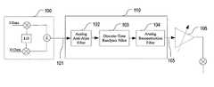
- the Stage 1 201 filter element frequency response 410 and 420 and a group delay curve 430are shown in FIG. 4 .
- trace 411shows the response from around 0 to around 1200 MHz.
- the vertical dashed lines in the vicinity of 412show the approximate location of the 40 MHz wide passband; and the vertical dashed lines in the vicinity of 413 show the corresponding image.
- the narrow scale frequency response graph 420shows a portion of the pass band such as from 421 to 422 .
- the group delay graph 430shows trace 431 which indicates a relatively constant group delay at approximately 15 ns across the frequency spectrum from around 570 MHz to around 630 MHz. It should be noted that the graphs 410 , 420 , and 430 do not reflect the inversion of alternate samples at the Stage 1 output sampler.
- FIG. 5a diagram for Stage 2 202 , which can be used to implement a decimate-by-4 polyphase filter, is shown in FIG. 5 .
- the Stage 2 202can include three 12-tap FIR filters 502 , 503 , and 504 having three different coefficient sets respectively.
- the Stage 2 202can further include a 6 tap delay line 505 , an output summing node 506 , and an output sampler 507 . It should be noted that in the Stage 2 202 , there is no alternate sample polarity inversion in the output sampler. Input samples arrive from the Stage 1 201 at 501 at a 1371.5 MHz rate.
- phase 520 , 530 , 540 , and 550are generated from the basic 1371.5 MHz clock.
- the four phases 520 , 530 , 540 , and 550are used to clock every fourth sample into a given branch in, for example, a round robin order such as from top to bottom and so on.
- filter coefficientsare different for the three 12-tap FIR filters 502 , 503 , and 504 , the smallest filter coefficient is, for example, 0.000632, which corresponds to an attenuation of 64.0 dB.
- the output of the three 12-tap FIR filters 502 , 503 , and 504 , and the 6 tap delay line 505can be output and combined in a summer 506 , and sampled in a sampler 507 at 342.875 MHz clock Phase 1 520 for output to Stage 3 203 at 508 .
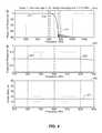
- the frequency response and group delay for the Stage 2 202is shown in FIG. 6 .
- wide scale frequency response graph 610the vertical dashed lines in the vicinity of 611 and in the vicinity of 612 demarcate a 40 MHz passband, with the vertical dashed lines in the vicinity of 612 showing the image with the lowest frequency.
- narrow scale frequency response graph 620the passband region is noted with greater resolution, for example, between around 621 and around 622 .
- the group delay graph 630is shown where trace 631 is relatively flat at around 18 ns across the passband.
- the Stage 3 203 filter elementcan be a long FIR filter 622 operating at a sampling rate of 342.875 MHz 630 . It will be appreciated that by using the term “long” in connection with the FIR filter 622 , an approximation of an Infinite Impulse Response filter is intended. Such filters can use a large number of taps or can be designed in a manner to approximate an IIR response as will be appreciated.
- the response of the FIR filter 622is symmetric with respect to an 85.71875 MHz center frequency, which is exactly one quarter of the sampling rate. Note that the filter's center frequency (85.71875 MHz) is slightly different from the “second IF” (85.875 MHz).
- the specific choice of center frequencyyields a stage 3 design in which around half of the coefficients are zero.
- the FIR filter 622has an order of 294, such as 0 to 294 coefficients or 295 total coefficients. Of the 295 coefficients, only 147 have non-zero values. The smallest coefficient has the value of, for example, 0.000108775 relative to the value of the center tap, which requires an attenuation of 79.3 dB. It will further be appreciated that samples generated from a sampler 620 can be output to the Stage 4 204 at 621 .
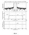
- the frequency response and group delay for the Stage 3 203is shown in FIG. 8 .
- the vertical dashed lines in the vicinity of 812demarcate an approximate 20 MHz passband centered at 85.71875 MHz as noted above, section 811 shows the low frequency stop band with a corresponding high frequency stop band to the right of passband section 812 .
- the passband regionis noted with greater resolution, for example, between around 822 and around 823 centered, as noted at 821 and around 85.71875 MHz.
- the group delay graph 830is shown where trace 831 is relatively flat at around 428 ns across the passband.
- the Stage 4 204is a 1:4 polyphase interpolator using three 12-tap FIR filters 902 , 903 , and 904 having three different coefficient sets respectively and a 6 tap delay line 905 in the manner described, for example, in connection with FIG. 5 , arranged as in FIG. 9 .
- Samplesare received from Stage 3 at 901 a 342.875 MHz sampling rate.
- Each input sampleis clocked into each of the four branches associated with the three 12-tap FIR filters 902 , 903 , 904 , and the 6 tap delay line 905 , which are updated at the same time.
- the equivalent of a single pole, quadruple throw (1P4T) rotary switch 906steps through positions at a 1371.5 MHz rate 909 , sampling each of the four branch values before updating in an inversion sampler 907 which is configured to invert the polarity of every other sample converting the 85.875 MHz “second IF” back to 600 MHz for output to the Stage 5 205 at 908 .
- the frequency response and group delay for the Stage 4 204is the same as that for Stage 2 as show, for example, in FIG. 6 .
- the Stage 5 205is a 1:2 polyphase interpolator using components such as a 42 tap Finite Impulse Response (FIR) filter 1002 and a 21 clock cycle delay line 1003 as described above, for example, in connection with the Stage 1 201 .
- the output from the Stage 4 , 204can be input to the 42 tap Finite Impulse Response (FIR) filter 1002 and the 21 clock cycle delay line 1003 for processing in accordance with a 1371.5 MHz clock 1008 .
- the output of the 42 tap Finite Impulse Response (FIR) filter 1002 and the 21 clock cycle delay line 1003can be sampled by the equivalent of a rotary switch 1004 which can be input to sampler 1005 .
- the output at 1006is the IF signal output which can be gain controlled or the like as noted above.
- the present inventioncan be used to replace components which may be expensive or redundant in certain wireless repeaters.
- FIG. 11a more common approach to performing repeating in accordance with various exemplary embodiments, is shown for example in FIG. 11 .
- the antenna 1100transforms received radio waves to a voltage signal and feeds the voltage signal to an isolator 1105 .
- the isolatormay not be included depending upon the type of different antenna configurations used. Two of these embodiments including such antenna configurations will be described below.
- the isolator 1105allows a signal to pass from the antenna 1100 to a Low Noise Amplifier (LNA) 1110 and from a power amplifier 1125 to the antenna 1100 , but blocks or isolates the LNA 1110 from the power amplifier 1125 .
- LNALow Noise Amplifier
- Other embodiments of the isolator 1105could include, but are not limited to, circulators, directional couplers, splitters, and switches. For instance, switches may be used with the dual directional antenna configuration.
- a signal received and transformed by the antenna 1100 passing through the isolator 1105is fed to the LNA 1110 , which amplifies the signal and sets the noise level at that point.
- a signal amplified by the LNA 1110is fed to an RF splitter 1115 , which performs an RF power splitting, or coupling, function on the signal to split the signal into two different paths for frequency F 1 and F 2 for example.
- the splitter 1115could also be a directional coupler or any device that can separate one signal into two signals.
- the antenna 1100 , the LNA 1110 and the RF splitter 1115are the primary components forming a receiver in an exemplary repeater. Further, one skilled in the art will readily recognize that the antenna 1100 , the power amplifier 1125 , the amplifier 1130 , the filter 1135 , the switch 1145 and the mixer 1150 are the primary components forming a transmitter in an exemplary repeater. In an alternative embodiment, the antenna 1100 and isolator 1105 could be replaced with dual antennas isolated by directivity or polarization, or other techniques known to those skilled in the art. Such dual antennas could be connected to the LNA 1110 and the power amplifier 1125 .
- the output of the splitter 1115can be input to an exemplary discrete-time bandpass filter unit 1116 as described herein wherein mixers 1120 , 1121 can act as frequency conversion devices that mix signals passed from the splitter 1115 with signals output from the local oscillators 1140 , 1141 at respective frequencies designated as LO 1 , LO 2 to produce intermediate frequency (IF) or typically lower frequency signals.
- IFintermediate frequency
- the local oscillators 1140 , 1141are tuned to the different frequencies LO 1 , LO 2 such that two different signals at two different frequencies fed from the splitter 1115 can be converted to a common IF frequency.
- the mixers 1120 and 1121can be integrated into the discrete-time bandpass filter 1116 or can be used externally to feed splitters 1123 and 1123 which are integrated into the discrete-time bandpass filter 1116 .
- the splitters 1123 , 1124which operate the same as the splitter 1115 described above, separate the IF signals output from the respective mixers 1120 , 1121 into two different paths.
- One path from each of the splitters 1123 , 1124goes to delay lines or delay line filters 1160 , 1161 , respectively, while the other path from each of the splitters 1123 , 1124 goes to detection filters 1165 , 1166 , respectively.
- delay line filters 1160 , 1161 and detection filters 1165 , 1166can be integrated into the discrete time bandpass filter unit 1116 .
- the delay line filters 1160 , 1161or the equivalent functions carried out using the discrete-time bandpass filter unit 1116 , which are preferably band pass filters with delays, remove all outputs from the mixing operation except the desired frequency components.
- the delay line filters 1160 , 1161have a sufficient time delay such that the detection and control unit 1162 can detect which of the two RF frequencies is present and perform control functions described below prior to the signals being available at the output of the delay line filters 1160 , 1161 , as detectors 1170 , 1171 are in parallel with the delay line filters 1160 , 1161 within the discrete-time bandpass filter unit 1116 . It should be noted that if it is acceptable to truncate a portion of the first part of the RF signal, then the delay line filters 1160 , 1161 would not need specified delays.
- the mixers 1120 , 1121 , the splitters 1123 , 1124 and the delay line filters 1160 , 1161are the primary components forming a frequency converter in the exemplary repeater.
- the detection filters 1165 , 1166 in the detection and control unit 1162also perform the same type of band pass filtering as the delay line filters 1160 , 1161 , and thus can be integrated into the discrete-time bandpass filter unit 1116 .
- the main differenceis that the detection filters 1165 , 1166 are preferably fast filters without specified long time delays.
- the detection filters 1165 , 1166preferably do not require the same level of filtering performance as the delay line filters 1160 , 1161 , although one skilled in the art would recognize that varying filter performance within the confines of performing the filtering objective can be a design choice notwithstanding the challenges of incorporating the respective functions into the discrete-time bandpass filter element 1116 in accordance with various exemplary embodiments.
- filters or devices other than band pass filtersmight be used to perform the above discussed band pass functions.
- Power detectors 1170 , 1171are simple power detection devices that detect if a signal is present on either of the respective frequencies F 1 , F 2 and provide a proportional voltage output if the signal is present.
- Many types of analog detectors that perform this functionmay be used and can either be integrated or can be external devices.
- such detectorscould include, but are not limited to, diode detectors. Such diode detection could be performed at RF, IF or base band. Detectors providing higher performance than simple power detectors may also be used. These detectors may be implemented as matched filters at RF or IF using SAW devices, and matched filtering or correlation at base band after analog to digital conversion.
- the power detectors 1170 , 1171are used to determine the presence of a wireless transmission on one of the two IF channels by comparing signals on the two IF channels with a threshold.
- a thresholdcould be predetermined or calculated using for example, a portion of the discrete-time bandpass filter element 1116 based on monitoring the channels over time to establish a noise floor.
- the power detectors 1170 , 1171may be used to determine start and stop times of a detected transmission.
- the proportional voltage output by one of the power detectors 1170 , 1171 in response to signal detectionwill be used by the microprocessor 1185 to control the retransmission of the signal.
- the power detectioncan be placed earlier or later in the signal processing path, as it is possible to detect signals so that the retransmission process may be switched on or off.
- techniques for determining or limiting transmission timecan be employed, including but not limited to placing a time limit on retransmission using a timer.
- the filters 1175 , 1176are low pass filters and preferably have narrower bandwidths than the detection filters 1165 , 1166 .
- the filters 1175 , 1176are required to remove the high frequency components that remain after signal detection in the power detectors 1170 , 1171 and to provide an increase in signal to noise ratio by providing processing gain by reducing the detection signal bandwidth.
- the signals output from low pass filters 1175 , 1176are input to conventional analog to digital converters 1180 , 1181 . It will further be appreciated that while analog to digital converters 1180 and 1181 are shown as being outside the discrete-time bandpass filter unit 1116 .
- digital to analog convertersmay be used in place of analog to digital converters 1180 and 1181 and a set of analog to digital converters can be used, for example, at the output of the splitters 1123 and 1124 , inside the discrete-time bandpass filter unit 1116 , although, as noted, such a configuration can lead to additional expense.
- the microprocessor 1185which can also be described as a logic state machine, digital signal processor, or other digital processing and control device, can be programmed to implement all necessary control algorithms to, with a high probability of certainty, detect the presence of either F 1 or F 2 and initiate appropriate control functions.
- comparator detectors(not shown) with adjustable threshold controls may be used in place of the analog to digital converters 1180 , 1181 and the microprocessor 1185 particularly in an analog implementation of the discrete-time bandpass filter unit 1116 .
- control outputs of the microprocessor 1185could be alternatively connected directly to digital gates to control the switching where input to these gates is taken directly from the comparator detector outputs. Further input to the digital logic may come from the microprocessor 1185 to allow for override control to the settings provided from the comparator detector's output.
- microprocessor 1185would continue to control the detection and display functions, but; however, it is likely the control of the variable gain amplifier 1130 would be controlled directly from the power detectors 1170 , 1171 using analog signals.
- Logarithmic amplifiers(not shown) can work off the envelope of the low pass filters can control the functions of an exemplary automatic gain control.
- Feedback to a usercan be controlled by the microprocessor 1185 via an indicator 1190 which could be, but is not limited to, a series of light emitting diodes.
- Feedback to the usercould be an indication that the wireless repeater 200 is in an acceptable location such that either or both frequencies from the wireless access point 100 and the client device 105 can be detected, or that power is supplied to the wireless repeater 200 .
- the microprocessor 1185controls switches 1145 , 1155 .
- the switch 1155is switched to allow the detected signal, either on F 1 or F 2 , which is at an IF frequency, to be routed to the input of a frequency converter 1150 , which is another frequency translation device similar to the mixers 1120 , 1121 .
- the microprocessor 1185will set the switch 1145 to allow a signal from the appropriate one of the local oscillators 1140 , 1141 to be routed to the mixer 1150 so that the IF frequency at the input to the frequency converter 1150 is translated to the proper frequency at the output thereof.
- a physical layer repeater circuit 1200is shown for receiving on two frequency channels.
- a local oscillator LO 1 1201can be used to drive one set of receive and transmit channels for down-conversion and up-conversion through an input mixer 1210 on the receive side and an output mixer 1235 on the transmit side.
- the input mixer 1210mixes a signal received from, for example, an antenna and inputs the mixed signal to amplifier 1212 as will be appreciated.
- the output of amplifier 1212passes through a bandpass filter element 1214 the output of which is transferred to amplifier 1216 at intermediate frequency of, for example, 594 MHz.
- the output of the IF stage amplifier 1216is transferred to analog-to-digital converter (ADC) 1218 which is preferably a 14 bit converter.
- ADCanalog-to-digital converter
- the other set of receive and transmit channelsare coupled to LO 2 1202 , which is used for down down-conversion and up-conversion through an input mixer 1211 on the receive side and an output mixer 1236 on the transmit side.
- the input mixer 1211mixes a signal received from, for example, an antenna and inputs the mixed signal to amplifier 1213 as will be appreciated.
- the output of amplifier 1213passes through a bandpass filter element 1215 the output of which is transferred to amplifier 1217 at intermediate frequency of, for example, 462 MHz.
- the output of the IF stage amplifier 1217is transferred to ADC converter 1219 which is also preferably a 14 bit converter.
- the ADC converters 1218 and 1219are driven, for example, at 132 MHz sampling by a clock generated from divider 1205 , which is coupled to an LO 3 1203 .
- the LO 1 1201 , the LO 2 1202 and the LO 3 1203are all coupled to a reference source 1204 which generates, for example, a 2112 MHz clock reference. In such a way, all the processing elements will be synchronized to a common clock reference for more accurate processing.
- the outputs of the ADC 1218 and the ADC 1219are coupled to dedicated signal processing blocks such as a signal processing block A (SPBA) 1220 and a signal processing block B (SPBB) 1221 .
- SPBA 1220 and the SPBB 1221are coupled with a signal processing bus 1222 .
- a state machine 1240can be used to help control the operation of the repeater by generating an output state or state vector Si+1 1242 based on a previous state or state vector Si 1241 as will be appreciated by one of ordinary skill in the art.
- the SPBA 1220 and the SPBB 1221When a packet is ready to be retransmitted, the SPBA 1220 and the SPBB 1221 output the baseband data to the multiplexer 1228 which selects the appropriate one of the SPBA 1220 and the SPBB 1221 for output based on which channel the signal was detected and subsequently processed on.
- the output of the multiplexer 1228which is typically a 14 to 16 bit digital value is coupled to a digital-to-analog converter (DAC) 1229 which outputs an analog signal.
- DACdigital-to-analog converter
- the analog output of the DAC 1229is coupled to a low pass filter (LPF) element 1230 to remove any quantizing noise and the output of the LPF element 1230 is coupled as a modulating input to a vector modulator (VM) 1231 a digital IF frequency signal at for example, 528 MHz to begin up-conversion.
- VMvector modulator
- the output of the VM 1231is input to an amplifier 1232 the output of which is coupled to a bandpass filter (BPF) element 1233 .
- BPFbandpass filter
- the output of BPF element 1233is coupled to an RF switch 1234 and depending on which channel the information is to be repeated on, the RF switch 1234 will direct the signal to an output mixer 1235 or an output mixer 1236 , where the modulated IF signal will be mixed with a 3006-3078 MHz signal from LO 1 1201 or an 1960-2022 MHz signal each with a 5.8 MHz offset. It will further be appreciated that under certain circumstances, signal samples from the SPBA 1220 and the SPBB 1221 can be stored in a memory such as a memory 1250 .
- an exemplary physical layer repeateris capable of receiving two different frequencies simultaneously, determining which channel is carrying a signal associated with, for example, the transmission of a packet, translating from the original frequency channel to an alternative frequency channel and retransmitting the frequency translated version of the received signal on the alternative channel. Details of basic internal repeater operation in accordance with various embodiments may be found, for example, in co-pending PCT Application No. PCT/US03/16208.
- the physical layer repeatercan receive and transmit packets at the same time on different frequency channels thereby extending the coverage and performance of the connection between an AP and a client, and between peer-to-peer connections such as from one client unit to another client unit.
- the repeaterWhen many units are isolated from one another, the repeater further acts as a wireless bridge allowing two different groups of units to communicate where optimum RF propagation and coverage or, in many cases, any RF propagation and coverage was not previously possible.
- a series of digital signal processing functionscan be used to perform, for example, detection and delay.
- a physical layer repeater scenario 1300is shown where various digital filter components are connected to provide filtering functions.
- Digital data 1301 received from, for example, an ADCcan be input at a digital interface 1303 according to data clock 1302 at a clocking rate of 132 MHz.
- Portions of the digital signalcan be input to an auxiliary digital filter 1304 the output of which can be used, inter alia, for power detection at a power detector and comparator 1305 .
- the signal level threshold for at least initial or coarse detectioncan be established in the power detector and comparator 1305 with a threshold THRESH_P 1307 .
- the output of the power detector and comparator 1306would accordingly be a signal indicative that the threshold has been crossed such as a DETECT_P 1308 signal.
- a coarse channel width detection signalcan also be output as a 20/40 MHz 1309 signal.
- the digital signalcan also be coupled to a correlator detector and comparator 1320 , which receives the filtered output signal from the auxiliary digital filter 1304 .
- the correlator detector and comparator 1320can be provided with a comparator threshold input such as a THRESH_C 1306 .
- the correlator detector and comparator 1320determines the presence of orthogonal frequency division multiplexing (OFDM) and the presence of a barker signal indicating the use of direct sequence (DS) spread spectrum modulation. Accordingly, the output of the correlator detector and comparator 1320 is an OFDM DETECT signal 1322 , a BARKER_C DETECT signal 1323 , and a phase estimate 1321 .
- the correlator detector and comparator 1320can also output a more refined indication of the channel width for example as a 20/40 MHZ signal 1324 .
- the processed outputs 1325can be forwarded to an 802.11 demodulator.
- the digital signal 1301can also be forwarded to a digital delay pipeline 1310 , where it can be delayed until certain processing has been conducted as will be appreciated.
- a 20 MHz digital filter 1312can be used to process a signal transmitted on a 20 MHz channel or a 40 MHz digital filter 1313 can be used to process a signal transmitted on a 40 MHz channel.
- An additional digital filter 1314can be used to conduct additional filtering.
- the digital filterscan be coupled to each other and to additional signal processing blocks such as the signal processing blocks A 1220 and B 1221 as shown in FIG. 12 , through an inter signal processing block (ISPB) bus 1311 which is also shown in FIG. 12 as the bus 1222 .
- ISPBinter signal processing block
- the output of the appropriate one or more of the digital filterscan be input to multiplexer 1315 where control inputs for 40 MHz 1318 and 20 MHz 1319 can be used to select which of the filter outputs will be transmitted.
- the output of a modulatorcan also be coupled to the multiplexer 1315 for transmitting information demodulated from the signal if appropriate.
- the output of the multiplexer 1315is input to a frequency converter and interpolator 1316 for up conversion and output at 1330 to the RF transmitter section (not shown).
Landscapes
- Engineering & Computer Science (AREA)
- Computer Networks & Wireless Communication (AREA)
- Signal Processing (AREA)
- Physics & Mathematics (AREA)
- Computer Hardware Design (AREA)
- Mathematical Physics (AREA)
- Radio Relay Systems (AREA)
Abstract
Description
| TABLE 1 |
| Sample Filter Characteristics. |
| Characteristic | |||
| Center frequency |
| 600 | MHz | ||
| Pass bandwidth | >18 | MHz | |
| Passband ripple | <0.25 | dB | |
| Stop bandwidth | <26 | MHz | |
| Stop band attenuation | >50 | dB | |
| Group delay | >300 | ns | |
| Sampling aperture jitter | <4.6 | ps | |
| TABLE 2 |
| Filter Stage Sampling Rates. |
| Sampling Rates (MHz) | Sampling Rates (MHz) | ||
| for 600 MHz IF | for fCMHz IF |
| Stage | Input | Input | Output | ||
| 1 | 2743.000 | 1371.500 | (32/7)*fC | (16/7)* |
| 2 | 1371.500 | 342.875 | (16/7)*fC | (4/7)* |
| 3 | 342.875 | 342.875 | (4/7)*fC | (4/7)* |
| 4 | 342.875 | 1371.500 | (4/7)*fC | (16/7)* |
| 5 | 1371.500 | 2743.000 | (16/7)*fC | (32/7)*fC |
| TABLE 3 |
| Filter Group Delay, by Stage. |
| Group Delay | |||
| Stage | (ns) | ||
| 1 | 16 | ||
| 2 | 17 | ||
| 3 | 429 | ||
| 4 | 17 | ||
| 5 | 16 | ||
| Total | 495 | ||
Claims (22)
Priority Applications (1)
| Application Number | Priority Date | Filing Date | Title |
|---|---|---|---|
| US11/340,860US8078100B2 (en) | 2002-10-15 | 2006-01-27 | Physical layer repeater with discrete time filter for all-digital detection and delay generation |
Applications Claiming Priority (8)
| Application Number | Priority Date | Filing Date | Title |
|---|---|---|---|
| US41828802P | 2002-10-15 | 2002-10-15 | |
| US42654102P | 2002-11-15 | 2002-11-15 | |
| US10/531,078US8060009B2 (en) | 2002-10-15 | 2003-10-15 | Wireless local area network repeater with automatic gain control for extending network coverage |
| PCT/US2003/029130WO2004036789A1 (en) | 2002-10-15 | 2003-10-15 | Wireless local area network repeater with automatic gain control for extending network coverage |
| US10/533,589US8111645B2 (en) | 2002-11-15 | 2003-11-17 | Wireless local area network repeater with detection |
| PCT/US2003/035050WO2004047308A2 (en) | 2002-11-15 | 2003-11-17 | Wireless local area network repeater with detection |
| US64738505P | 2005-01-28 | 2005-01-28 | |
| US11/340,860US8078100B2 (en) | 2002-10-15 | 2006-01-27 | Physical layer repeater with discrete time filter for all-digital detection and delay generation |
Related Parent Applications (5)
| Application Number | Title | Priority Date | Filing Date |
|---|---|---|---|
| PCT/US2003/029130Continuation-In-PartWO2004036789A1 (en) | 2002-10-15 | 2003-10-15 | Wireless local area network repeater with automatic gain control for extending network coverage |
| US10/531,078Continuation-In-PartUS8060009B2 (en) | 2002-10-15 | 2003-10-15 | Wireless local area network repeater with automatic gain control for extending network coverage |
| PCT/US2003/035050Continuation-In-PartWO2004047308A2 (en) | 2002-10-15 | 2003-11-17 | Wireless local area network repeater with detection |
| US10/533,589Continuation-In-PartUS8111645B2 (en) | 2002-10-15 | 2003-11-17 | Wireless local area network repeater with detection |
| US10533589Continuation-In-Part | 2003-11-17 |
Publications (2)
| Publication Number | Publication Date |
|---|---|
| US20060195883A1 US20060195883A1 (en) | 2006-08-31 |
| US8078100B2true US8078100B2 (en) | 2011-12-13 |
Family
ID=36933266
Family Applications (1)
| Application Number | Title | Priority Date | Filing Date |
|---|---|---|---|
| US11/340,860Expired - Fee RelatedUS8078100B2 (en) | 2002-10-15 | 2006-01-27 | Physical layer repeater with discrete time filter for all-digital detection and delay generation |
Country Status (1)
| Country | Link |
|---|---|
| US (1) | US8078100B2 (en) |
Cited By (12)
| Publication number | Priority date | Publication date | Assignee | Title |
|---|---|---|---|---|
| US20110223960A1 (en)* | 2010-03-10 | 2011-09-15 | Fujitsu Limited | System and Method for Implementing Power Distribution |
| US8422540B1 (en) | 2012-06-21 | 2013-04-16 | CBF Networks, Inc. | Intelligent backhaul radio with zero division duplexing |
| US8498234B2 (en) | 2002-06-21 | 2013-07-30 | Qualcomm Incorporated | Wireless local area network repeater |
| US8559379B2 (en) | 2006-09-21 | 2013-10-15 | Qualcomm Incorporated | Method and apparatus for mitigating oscillation between repeaters |
| US8649418B1 (en) | 2013-02-08 | 2014-02-11 | CBF Networks, Inc. | Enhancement of the channel propagation matrix order and rank for a wireless channel |
| US20140073266A9 (en)* | 2010-08-30 | 2014-03-13 | Physical Devices, Llc | Methods, systems, and non-transitory computer readable media for wideband frequency and bandwidth tunable filtering |
| US8885688B2 (en) | 2002-10-01 | 2014-11-11 | Qualcomm Incorporated | Control message management in physical layer repeater |
| US8995505B2 (en) | 2012-11-30 | 2015-03-31 | Qualcomm Incorporated | Sliding if transceiver architecture |
| US9350401B2 (en) | 2010-08-30 | 2016-05-24 | Physical Devices, Llc | Tunable filter devices and methods |
| US9519062B2 (en) | 2012-02-28 | 2016-12-13 | Physical Devices, Llc | Methods, systems, and computer readable media for mitigation of in-band interference of global positioning system (GPS) signals |
| US9866267B2 (en) | 2014-02-21 | 2018-01-09 | Physical Devices, Llc | Devices and methods for diversity signal enhancement and cosite cancellation |
| US20190132059A1 (en)* | 2016-06-20 | 2019-05-02 | Sony Corporation | Communication apparatus and communication system |
Families Citing this family (25)
| Publication number | Priority date | Publication date | Assignee | Title |
|---|---|---|---|---|
| CN101449602A (en)* | 2006-05-18 | 2009-06-03 | 皇家飞利浦电子股份有限公司 | System and method for detecting temporarily unused bandwidth in the radio frequency spectrum |
| JP4927943B2 (en)* | 2006-05-19 | 2012-05-09 | クゥアルコム・インコーポレイテッド | Wireless repeater with master / slave configuration |
| RU2420886C1 (en)* | 2007-03-02 | 2011-06-10 | Квэлкомм Инкорпорейтед | Repeater configuration |
| US8902365B2 (en)* | 2007-03-14 | 2014-12-02 | Lance Greggain | Interference avoidance in a television receiver |
| US8330873B2 (en)* | 2007-03-14 | 2012-12-11 | Larry Silver | Signal demodulator with overmodulation protection |
| US7783207B2 (en)* | 2007-06-27 | 2010-08-24 | Alcatel-Lucent Usa Inc. | Automatic threshold voltage adjustment circuit for dense wavelength division multiplexing or packet transport system and method of operating the same |
| KR101048444B1 (en) | 2007-09-03 | 2011-07-11 | 삼성전자주식회사 | Location Estimation Device and Method in Wireless Communication System |
| US9577608B2 (en)* | 2009-08-14 | 2017-02-21 | Qualcomm Incorporated | Discrete time lowpass filter |
| US8619840B2 (en)* | 2010-02-26 | 2013-12-31 | Qualcomm Incorporated | Apparatus and methods for sampling rate conversion for wireless transceivers |
| US8325865B1 (en)* | 2011-07-31 | 2012-12-04 | Broadcom Corporation | Discrete digital receiver |
| US9641400B2 (en) | 2014-11-21 | 2017-05-02 | Afero, Inc. | Internet of things device for registering user selections |
| US10291595B2 (en) | 2014-12-18 | 2019-05-14 | Afero, Inc. | System and method for securely connecting network devices |
| US9832173B2 (en) | 2014-12-18 | 2017-11-28 | Afero, Inc. | System and method for securely connecting network devices |
| US20160180100A1 (en) | 2014-12-18 | 2016-06-23 | Joe Britt | System and method for securely connecting network devices using optical labels |
| US9704318B2 (en) | 2015-03-30 | 2017-07-11 | Afero, Inc. | System and method for accurately sensing user location in an IoT system |
| US10045150B2 (en) | 2015-03-30 | 2018-08-07 | Afero, Inc. | System and method for accurately sensing user location in an IoT system |
| US9537455B2 (en) | 2015-04-10 | 2017-01-03 | Wilson Electronics, Llc | Multiplex detector signal boosters |
| FR3036902B1 (en)* | 2015-05-26 | 2018-11-16 | Commissariat A L'energie Atomique Et Aux Energies Alternatives | VERSATILE RADIO RECEIVER ARCHITECTURE |
| US9717012B2 (en) | 2015-06-01 | 2017-07-25 | Afero, Inc. | Internet of things (IOT) automotive device, system, and method |
| US9699814B2 (en) | 2015-07-03 | 2017-07-04 | Afero, Inc. | Apparatus and method for establishing secure communication channels in an internet of things (IoT) system |
| US9729528B2 (en) | 2015-07-03 | 2017-08-08 | Afero, Inc. | Apparatus and method for establishing secure communication channels in an internet of things (IOT) system |
| US10015766B2 (en) | 2015-07-14 | 2018-07-03 | Afero, Inc. | Apparatus and method for securely tracking event attendees using IOT devices |
| US9793937B2 (en)* | 2015-10-30 | 2017-10-17 | Afero, Inc. | Apparatus and method for filtering wireless signals |
| US10178530B2 (en) | 2015-12-14 | 2019-01-08 | Afero, Inc. | System and method for performing asset and crowd tracking in an IoT system |
| US10523305B2 (en)* | 2017-05-11 | 2019-12-31 | Wilson Electronics, Llc | Variable channelized bandwidth booster |
Citations (273)
| Publication number | Priority date | Publication date | Assignee | Title |
|---|---|---|---|---|
| US3363250A (en) | 1965-07-20 | 1968-01-09 | Jacobson Irving | Monitoring system for remote radio control |
| US4000467A (en) | 1975-10-24 | 1976-12-28 | Bell Telephone Laboratories, Incorporated | Automatic repeater stressing |
| US4001691A (en) | 1975-01-30 | 1977-01-04 | Gruenberg Elliot | Communications relay system |
| US4061970A (en) | 1976-05-19 | 1977-12-06 | E.L.A.P. | Transmission system and repeater stations therefor |
| US4081752A (en) | 1975-05-30 | 1978-03-28 | Sanyo Electric Co., Ltd. | Digital frequency synthesizer receiver |
| US4124825A (en) | 1976-09-21 | 1978-11-07 | The Post Office | Signal level stabilizer |
| US4204016A (en) | 1975-07-25 | 1980-05-20 | Chavannes Marc A | Reinforced paper products |
| US4334323A (en) | 1980-09-08 | 1982-06-08 | Zenith Radio Corporation | Self tracking tuner |
| US4368541A (en) | 1980-06-30 | 1983-01-11 | Evans Robert M | Multiplexing arrangement for a plurality of voltage controlled filters |
| US4509206A (en) | 1982-05-04 | 1985-04-02 | Thomson-Csf | Receiver for multicarrier signals protected from unwanted signals |
| US4679243A (en) | 1984-08-17 | 1987-07-07 | National Research Development Corporation | Data transmission using a transparent tone-in band system |
| US4701935A (en) | 1985-01-09 | 1987-10-20 | Nec Corporation | One frequency repeater for a digital microwave radio system with cancellation of transmitter-to-receiver interference |
| US4723302A (en) | 1986-08-05 | 1988-02-02 | A. C. Nielsen Company | Method and apparatus for determining channel reception of a receiver |
| US4777653A (en) | 1985-12-20 | 1988-10-11 | Telecommunications Radioelectriques Et Telephoniques T.R.T. | Apparatus for controlling transmission power over a digital radio communication channel |
| US4783843A (en) | 1986-05-23 | 1988-11-08 | Peninsula Engineering Group, Inc. | Split band filter for cellular mobile radio |
| US4820568A (en) | 1987-08-03 | 1989-04-11 | Allied-Signal Inc. | Composite and article using short length fibers |
| US4922259A (en) | 1988-02-04 | 1990-05-01 | Mcdonnell Douglas Corporation | Microstrip patch antenna with omni-directional radiation pattern |
| US5023930A (en) | 1987-08-03 | 1991-06-11 | Orion Industries, Inc. | Booster with detectable boost operation |
| US5095528A (en) | 1988-10-28 | 1992-03-10 | Orion Industries, Inc. | Repeater with feedback oscillation control |
| US5214788A (en) | 1989-05-10 | 1993-05-25 | Thomson - Csf | Process and device for information transmission between radioelectric transceivers of the same network operating in frequency hopping |
| US5220562A (en) | 1989-05-12 | 1993-06-15 | Hitachi, Ltd. | Bridge apparatus and a communication system between networks using the bridge apparatus |
| US5280480A (en) | 1991-02-21 | 1994-01-18 | International Business Machines Corporation | Source routing transparent bridge |
| GB2272599A (en) | 1992-11-12 | 1994-05-18 | Nokia Telecommunications Oy | A method of cellular radio communication and a cellular radio system for use in such method |
| US5333175A (en) | 1993-01-28 | 1994-07-26 | Bell Communications Research, Inc. | Method and apparatus for dynamic power control in TDMA portable radio systems |
| US5341364A (en) | 1992-06-02 | 1994-08-23 | At&T Bell Laboratories | Distributed switching in bidirectional multiplex section-switched ringtransmission systems |
| US5349463A (en) | 1990-08-17 | 1994-09-20 | Victor Company Of Japan | Optical radio repeater with signal quality detection |
| US5368897A (en) | 1987-04-03 | 1994-11-29 | Fujitsu Limited | Method for arc discharge plasma vapor deposition of diamond |
| US5371734A (en) | 1993-01-29 | 1994-12-06 | Digital Ocean, Inc. | Medium access control protocol for wireless network |
| US5373503A (en) | 1993-04-30 | 1994-12-13 | Information Technology, Inc. | Group randomly addressed polling method |
| US5383144A (en)* | 1990-11-20 | 1995-01-17 | Matsushita Electric Industrial Co., Ltd. | Subsampling method and interpolation method of digital signals |
| JPH0779187A (en) | 1993-07-30 | 1995-03-20 | Alcatel Mobil Commun Fr | Method for covering shadow zone of mobile radio communication cellular system and radio repeater for implementing the same |
| US5408618A (en) | 1992-07-31 | 1995-04-18 | International Business Machines Corporation | Automatic configuration mechanism |
| US5408197A (en) | 1993-03-04 | 1995-04-18 | Mitsubishi Denki Kabushiki Kaisha | Automatic power control circuit for controlling transmitting power of modulated radio frequency signal |
| US5430726A (en) | 1991-01-18 | 1995-07-04 | Moorwood; Charles A. | Repeater interface controller with a shared data bus |
| US5446770A (en) | 1993-03-31 | 1995-08-29 | Matsushita Electric Industrial Co., Ltd. | Time division duplex transceiver |
| US5465251A (en) | 1992-06-23 | 1995-11-07 | International Business Machines Corporation | Network addressing |
| US5471642A (en) | 1994-01-28 | 1995-11-28 | Palmer; James K. | Re-broadcast system for a plurality of AM signals |
| US5485486A (en) | 1989-11-07 | 1996-01-16 | Qualcomm Incorporated | Method and apparatus for controlling transmission power in a CDMA cellular mobile telephone system |
| JPH0897762A (en) | 1994-09-26 | 1996-04-12 | Infuorabu:Kk | Repeater for mobile communication |
| US5509028A (en) | 1993-03-26 | 1996-04-16 | Matra Communication | Radio transmission method using repeater stations with spectrum reversal |
| EP0709973A1 (en) | 1994-10-24 | 1996-05-01 | Ntt Mobile Communications Network Inc. | Transmission power control scheme for mobile communication system |
| US5515376A (en) | 1993-07-19 | 1996-05-07 | Alantec, Inc. | Communication apparatus and methods |
| US5519619A (en) | 1994-03-14 | 1996-05-21 | Motorola, Inc. | Route planning method for hierarchical map routing and apparatus therefor |
| US5608755A (en) | 1994-10-14 | 1997-03-04 | Rakib; Selim | Method and apparatus for implementing carrierless amplitude/phase encoding in a network |
| US5610916A (en) | 1995-03-16 | 1997-03-11 | Bell Atlantic Network Services, Inc. | Shared receiving systems utilizing telephone cables as video drops |
| EP0523687B1 (en) | 1991-07-18 | 1997-05-14 | Fujitsu Limited | Mobile telecommunication system having an expanded operational zone |
| JPH09162903A (en) | 1995-12-08 | 1997-06-20 | Victor Co Of Japan Ltd | Radio transmission equipment |
| US5648984A (en) | 1994-08-10 | 1997-07-15 | Alcatel Networks Systems, Inc. | Multidirectional repeater for data transmission between electrically isolated and/or physically different signal transmission media |
| US5654979A (en) | 1995-01-13 | 1997-08-05 | Qualcomm Incorporated | Cell site demodulation architecture for a spread spectrum multiple access communication systems |
| US5676198A (en) | 1994-11-15 | 1997-10-14 | Sundstrand Corporation | Cooling apparatus for an electronic component |
| US5678177A (en) | 1992-07-14 | 1997-10-14 | 2777321 Canada Ltd. | RF repeaters for time division duplex cordless telephone system |
| US5684801A (en) | 1994-12-30 | 1997-11-04 | Lucent Technologies | Portable wireless local area network |
| US5697052A (en) | 1995-07-05 | 1997-12-09 | Treatch; James E. | Cellular specialized mobile radio system |
| JPH1032557A (en) | 1996-07-15 | 1998-02-03 | Nec Corp | Relay system, transmitter and repeater used for the same |
| US5726980A (en) | 1995-03-30 | 1998-03-10 | Northern Telecom Limited | Time division duplex communications repeater |
| US5732334A (en) | 1996-07-04 | 1998-03-24 | Mitsubishi Denki Kabushiki Kaisha | Radio transmitter and method of controlling transmission by radio transmitter |
| US5745846A (en) | 1995-08-07 | 1998-04-28 | Lucent Technologies, Inc. | Channelized apparatus for equalizing carrier powers of multicarrier signal |
| US5754540A (en) | 1995-07-18 | 1998-05-19 | Macronix International Co., Ltd. | Expandable integrated circuit multiport repeater controller with multiple media independent interfaces and mixed media connections |
| US5764636A (en) | 1996-03-28 | 1998-06-09 | Cisco Technology, Inc. | Color blocking logic mechanism for a high-performance network switch |
| EP0847146A2 (en) | 1996-12-05 | 1998-06-10 | Nec Corporation | A transmission power control apparatus for a mobile communication system |
| US5767788A (en) | 1996-03-19 | 1998-06-16 | Ness; James C. | Computer aided dispatch and locator cellular system |
| US5771174A (en) | 1995-12-21 | 1998-06-23 | Measurex Corporation | Distributed intelligence actuator controller with peer-to-peer actuator communication |
| EP0853393A1 (en) | 1996-06-27 | 1998-07-15 | Ntt Mobile Communications Network Inc. | Transmitted power controller |
| US5784683A (en) | 1995-05-16 | 1998-07-21 | Bell Atlantic Network Services, Inc. | Shared use video processing systems for distributing program signals from multiplexed digitized information signals |
| US5794145A (en) | 1996-06-07 | 1998-08-11 | Telxon Corporation | Mobile device multiband antenna system |
| JPH10242932A (en) | 1997-02-24 | 1998-09-11 | Victor Co Of Japan Ltd | Diversity receiver for frequency-division multiplex signal |
| US5812933A (en) | 1992-12-30 | 1998-09-22 | Radio Communication Systems Ltd. | Duplex RF repeater for personal communications system |
| US5815795A (en) | 1995-08-25 | 1998-09-29 | Sumitomo Electric Industries, Ltd. | Oscillation detecting system for wireless repeater |
| RU2120702C1 (en) | 1991-02-01 | 1998-10-20 | Бритиш Телекоммьюникейшнз Паблик Лимитед Компани | Method for decoding of single received current signal from sequence of two-channel encoded video signals and device which implements said method |
| US5825809A (en)* | 1996-01-20 | 1998-10-20 | Samsung Electronics Co., Ltd. | Digital filter having an energy level detector for selecting a coefficient |
| US5852629A (en) | 1993-12-10 | 1998-12-22 | Fujitsu Limited | Repeater |
| WO1998058461A1 (en) | 1997-06-16 | 1998-12-23 | Telefonaktiebolaget Lm Ericsson | Multiple code channel power control in a radio communication system |
| US5857144A (en) | 1996-08-09 | 1999-01-05 | Ericsson, Inc. | In-band vehicular repeater for trunked radio system |
| US5862207A (en) | 1995-03-06 | 1999-01-19 | Toshiba Corporation | Method and system for providing virtual telephone terminals |
| US5875179A (en) | 1996-10-29 | 1999-02-23 | Proxim, Inc. | Method and apparatus for synchronized communication over wireless backbone architecture |
| US5883884A (en) | 1996-04-22 | 1999-03-16 | Roger F. Atkinson | Wireless digital communication system having hierarchical wireless repeaters with autonomous hand-off |
| US5884181A (en) | 1996-01-19 | 1999-03-16 | Bell Communications Research, Inc. | Interference reduction in shared-frequency wireless communication systems |
| US5890055A (en) | 1995-07-28 | 1999-03-30 | Lucent Technologies Inc. | Method and system for connecting cells and microcells in a wireless communications network |
| US5907794A (en) | 1994-03-03 | 1999-05-25 | Nokia Telecommunications Oy | Controlling a subscriber station on a direct mode channel |
| US5963847A (en) | 1995-10-26 | 1999-10-05 | Ntt Mobile Communications Network Inc. | Booster system |
| US5963846A (en) | 1997-03-31 | 1999-10-05 | Motorola, Inc. | Method and system for repeating pages |
| US5987304A (en) | 1996-05-31 | 1999-11-16 | Allgon Ab | Repeater with variable bandwidth |
| US6005884A (en) | 1995-11-06 | 1999-12-21 | Ems Technologies, Inc. | Distributed architecture for a wireless data communications system |
| US6005855A (en) | 1995-04-28 | 1999-12-21 | Qualcomm Incorporated | Method and apparatus for providing variable rate data in a communications system using statistical multiplexing |
| US6014380A (en) | 1997-06-30 | 2000-01-11 | Sun Microsystems, Inc. | Mechanism for packet field replacement in a multi-layer distributed network element |
| JP2000031877A (en) | 1998-07-09 | 2000-01-28 | Sharp Corp | Mobile communication system |
| US6032194A (en) | 1997-12-24 | 2000-02-29 | Cisco Technology, Inc. | Method and apparatus for rapidly reconfiguring computer networks |
| JP2000082983A (en) | 1998-09-03 | 2000-03-21 | Kokusai Electric Co Ltd | Wireless relay amplifier |
| US6061548A (en) | 1997-07-17 | 2000-05-09 | Metawave Communications Corporation | TDMA repeater eliminating feedback |
| US6088570A (en) | 1998-11-24 | 2000-07-11 | Airnet Communications Corporation | Method and apparatus employing delay elements in multiple diversity paths of a wireless system repeater translator to allow for selective diversity and automatic level control in a time-division multiple access system |
| US6101400A (en) | 1997-08-20 | 2000-08-08 | Interwave Communications, Inc. | Methods and apparatus for improved base station transceivers |
| US6108364A (en) | 1995-08-31 | 2000-08-22 | Qualcomm Incorporated | Time division duplex repeater for use in a CDMA system |
| JP2000236290A (en) | 1999-02-15 | 2000-08-29 | Nec Eng Ltd | Satellite communications system |
| WO2000050971A2 (en) | 1999-02-25 | 2000-08-31 | Berkeley Concept Research Corporation | Multichannel distributed wireless repeater network |
| JP2000269873A (en) | 1999-03-12 | 2000-09-29 | Kokusai Electric Co Ltd | Wireless relay amplifier |
| US6128729A (en) | 1997-12-16 | 2000-10-03 | Hewlett-Packard Company | Method and system for automatic configuration of network links to attached devices |
| US6128512A (en) | 1995-09-06 | 2000-10-03 | Cisco Systems, Inc. | Cellular communication system with dedicated repeater channels |
| US6163276A (en) | 1999-05-17 | 2000-12-19 | Cellnet Data Systems, Inc. | System for remote data collection |
| GB2351420A (en) | 1999-06-23 | 2000-12-27 | Motorola Ltd | Power control in a radio communication system |
| JP2001016152A (en) | 1999-06-30 | 2001-01-19 | Mitsubishi Electric Corp | Wireless relay device |
| US6188694B1 (en) | 1997-12-23 | 2001-02-13 | Cisco Technology, Inc. | Shared spanning tree protocol |
| US6188719B1 (en) | 1996-09-17 | 2001-02-13 | Alcatel Espace | Radiocommunication system repeater |
| US6195051B1 (en) | 1999-04-08 | 2001-02-27 | Motorola, Inc. | Microstrip antenna and method of forming same |
| US6202114B1 (en) | 1997-12-31 | 2001-03-13 | Cisco Technology, Inc. | Spanning tree with fast link-failure convergence |
| US6215982B1 (en) | 1996-06-28 | 2001-04-10 | Cisco Systems, Inc. | Wireless communication method and device with auxiliary receiver for selecting different channels |
| JP2001111575A (en) | 1999-08-03 | 2001-04-20 | Matsushita Electric Ind Co Ltd | Wireless LAN cross channel conversion repeater device and wireless terminal device |
| US6222503B1 (en) | 1997-01-10 | 2001-04-24 | William Gietema | System and method of integrating and concealing antennas, antenna subsystems and communications subsystems |
| JP2001136115A (en) | 1999-11-01 | 2001-05-18 | Mitsubishi Electric Corp | Method for removing looping waves in antenna device for relay station |
| US6272351B1 (en) | 1996-12-19 | 2001-08-07 | Cisco Technology, Inc. | System and method for relaying signals to base stations in a wireless communications system |
| US20010018328A1 (en) | 2000-02-29 | 2001-08-30 | Yoshinori Ohkura | Radio relay system |
| US6285863B1 (en) | 1999-11-24 | 2001-09-04 | Lucent Technologies Inc. | System and method for providing automatic gain control with high dynamic range |
| US6298061B1 (en) | 1997-07-30 | 2001-10-02 | Cisco Technology, Inc. | Port aggregation protocol |
| US6304563B1 (en) | 1999-04-23 | 2001-10-16 | Qualcomm Incorporated | Method and apparatus for processing a punctured pilot channel |
| US6304575B1 (en) | 1998-08-31 | 2001-10-16 | Cisco Technology, Inc. | Token ring spanning tree protocol |
| US20010031646A1 (en) | 2000-01-10 | 2001-10-18 | Williams Terry L. | Packet based backhaul channel configuration for a wireless repeater |
| US20010040699A1 (en) | 1996-04-10 | 2001-11-15 | Hidefumi Osawa | Image processing apparatus and method |
| US20010050580A1 (en) | 1996-05-13 | 2001-12-13 | O'toole James E. | Radio frequency data communications device |
| US20010050906A1 (en) | 1996-05-28 | 2001-12-13 | Joseph P. Odenwalder | High data rate cdma wireless communication system |
| US6331792B1 (en) | 2000-06-30 | 2001-12-18 | Conexant Systems, Inc. | Circuit and method for unlimited range frequency acquisition |
| US20010054060A1 (en) | 2000-06-16 | 2001-12-20 | Fillebrown Lisa A. | Personal wireless network |
| US20020004924A1 (en) | 2000-05-24 | 2002-01-10 | Samsung Electronics Co., Ltd. | Data transmission apparatus and method for an HARQ data communication system |
| US6339694B1 (en) | 1998-03-30 | 2002-01-15 | Airnet Communications Corporation | Method and apparatus employing automatic RF muting and wireless remote control of RF downlink transmission for a wireless repeater |
| US6342777B1 (en) | 1997-03-04 | 2002-01-29 | Kokusai Electric Co., Ltd. | Time divisional duplex (TDD) system portable telephone relay device |
| WO2002008857A2 (en) | 2000-07-20 | 2002-01-31 | Cadence Design Systems, Inc. | A bridging apparatus for interconnecting a wireless pan and a wireless lan |
| JP2002033691A (en) | 2000-06-05 | 2002-01-31 | Sony Internatl Europ Gmbh | Active reflector and wireless data communication system |
| US20020018487A1 (en) | 2000-04-06 | 2002-02-14 | Song Chen | Virtual machine interface for hardware reconfigurable and software programmable processors |
| WO2002017572A2 (en) | 2000-08-18 | 2002-02-28 | Nortel Networks Limited | Seamless roaming options in an ieee 802.11 compliant network |
| US6363068B1 (en) | 1997-06-18 | 2002-03-26 | Nec Corporation | Bridge and method of improving transmission efficiency of the same |
| US6370369B1 (en) | 1999-06-23 | 2002-04-09 | Sony International (Europe) Gmbh | Network device and method employing omni-directional and directional antennas |
| US6370185B1 (en) | 1999-08-10 | 2002-04-09 | Airnet Communications Corporation | Translating repeater system with improved backhaul efficiency |
| JP2002111571A (en) | 2000-09-28 | 2002-04-12 | Nippon Telegr & Teleph Corp <Ntt> | Wireless repeater |
| US20020045461A1 (en) | 2000-10-18 | 2002-04-18 | David Bongfeldt | Adaptive coverage area control in an on-frequency repeater |
| US6377640B2 (en) | 1997-07-31 | 2002-04-23 | Stanford Syncom, Inc. | Means and method for a synchronous network communications system |
| US6377612B1 (en) | 1998-07-30 | 2002-04-23 | Qualcomm Incorporated | Wireless repeater using polarization diversity in a wireless communications system |
| US6385181B1 (en) | 1998-03-18 | 2002-05-07 | Fujitsu Limited | Array antenna system of wireless base station |
| US6384765B1 (en) | 1998-11-18 | 2002-05-07 | Celsiustech Electronics Ab | Repeater jamming transmitter and casing for the same |
| US6393299B1 (en) | 1997-07-15 | 2002-05-21 | Kabushiki Kaisha Toshiba | Radio communication equipment |
| US20020061031A1 (en) | 2000-10-06 | 2002-05-23 | Sugar Gary L. | Systems and methods for interference mitigation among multiple WLAN protocols |
| US6404775B1 (en) | 1997-11-21 | 2002-06-11 | Allen Telecom Inc. | Band-changing repeater with protocol or format conversion |
| US20020089945A1 (en) | 2000-11-08 | 2002-07-11 | Belcea John M. | Time division protocol for an ad-hoc, peer-to-peer radio network having coordinating channel access to shared parallel data channels with separate reservation channel |
| US20020101843A1 (en) | 2001-01-02 | 2002-08-01 | Z-Com, Inc. | Signal propagation method for wireless network |
| US20020102948A1 (en) | 2000-09-14 | 2002-08-01 | Stanwood Kenneth L. | System and method for wireless communication in a frequency division duplexing region |
| US20020109585A1 (en) | 2001-02-15 | 2002-08-15 | Sanderson Lelon Wayne | Apparatus, method and system for range extension of a data communication signal on a high voltage cable |
| US20020115409A1 (en) | 2001-02-21 | 2002-08-22 | Khayrallah Ali S. | Method to achieve diversity in a communication network |
| US6441781B1 (en) | 1998-11-11 | 2002-08-27 | Samsung Electronics Co., Ltd. | Digital correlator for a receptor of signals from satellite radio-navigation systems |
| US20020119783A1 (en) | 2000-12-27 | 2002-08-29 | Yair Bourlas | Adaptive call admission control for use in a wireless communication system |
| JP2002271255A (en) | 2001-03-12 | 2002-09-20 | Toshiba Digital Media Engineering Corp | Repeater equipment and interexchange method |
| US20020136268A1 (en) | 2001-01-25 | 2002-09-26 | Hongbing Gan | Approach for selecting communications channels based on performance |
| EP0715423B1 (en) | 1994-11-30 | 2002-10-02 | AT&T Corp. | Symbol error based power control for mobile telecommunication system |
| US20020141435A1 (en) | 2001-03-27 | 2002-10-03 | Motorola, Inc. | Slot format and method for increasing random access opportunities in a wireless communication system |
| US20020146026A1 (en) | 2000-05-14 | 2002-10-10 | Brian Unitt | Data stream filtering apparatus & method |
| US20020155838A1 (en) | 2000-06-19 | 2002-10-24 | Durrant Randolph L. | RF signal repeater, mobile unit position determination system using the RF signal repeater, and method of communication therefor |
| US6473131B1 (en) | 2000-06-30 | 2002-10-29 | Stmicroelectronics, Inc. | System and method for sampling an analog signal level |
| US20020159506A1 (en) | 1997-02-24 | 2002-10-31 | Siavash Alamouti | Vertical adaptive antenna array for a discrete multitone spread spectrum communications system |
| US20020163902A1 (en) | 2001-05-01 | 2002-11-07 | Ntt Docomo, Inc. | Mobile communication system, mobile communication method, wireless base station, mobile station, and program |
| US6480481B1 (en) | 1998-07-28 | 2002-11-12 | Samsung Electronics, Co., Ltd. | Gated transmission in control hold state in CDMA communication system |
| US20020177401A1 (en) | 2001-05-22 | 2002-11-28 | Judd Mano D. | Repeater for customer premises |
| US20030026363A1 (en) | 2001-07-31 | 2003-02-06 | Jan Stoter | Adaptive automatic gain control |
| US6535732B1 (en) | 1995-05-04 | 2003-03-18 | Interwave Communications International, Ltd. | Cellular network having a concentrated base transceiver station and a plurality of remote transceivers |
| US6539028B1 (en) | 1998-12-09 | 2003-03-25 | Kent Ridge Digital Labs | CSMA/CD wireless LAN |
| US6539204B1 (en) | 2000-09-29 | 2003-03-25 | Mobilian Corporation | Analog active cancellation of a wireless coupled transmit signal |
| US20030063583A1 (en) | 1997-11-03 | 2003-04-03 | Roberto Padovani | Method and apparatus for high rate packet data transmission |
| US6549542B1 (en) | 1998-10-20 | 2003-04-15 | Samsung Electronics Co, Ltd. | Variable channel device for wideband CDMA system |
| US6549567B1 (en) | 1994-09-20 | 2003-04-15 | Time Domain Corporation | Full duplex ultrawide-band communication system and method |
| US6563468B2 (en) | 2001-04-27 | 2003-05-13 | Tyco Electronics Logistics Ag | Omni directional antenna with multiple polarizations |
| US6574198B1 (en) | 2000-07-06 | 2003-06-03 | Ericsson Inc. | Systems and methods for maintaining a signaling link in a communications network |
| JP2003174394A (en) | 2001-12-06 | 2003-06-20 | Hitachi Kokusai Electric Inc | Communication equipment |
| JP2003198442A (en) | 2001-12-28 | 2003-07-11 | Hitachi Ltd | Wireless transmission system for multipoint relay and wireless device used therefor |
| US20030139175A1 (en) | 2001-01-20 | 2003-07-24 | Samsung Electronics Co., Ltd. | System and method for remotely controlling a mobile terminal |
| JP2003244050A (en) | 2002-02-14 | 2003-08-29 | Hitachi Cable Ltd | Repeater transmission power control method |
| US20030179734A1 (en) | 2002-03-22 | 2003-09-25 | Nec Corporation | Wireless LAN base station capable of carrying out automatic matching for radio channels |
| US6628624B1 (en) | 1998-12-09 | 2003-09-30 | Cisco Technology, Inc. | Value-added features for the spanning tree protocol |
| US20030185163A1 (en) | 2002-03-27 | 2003-10-02 | Bertonis James G. | System and method for wireless cable data transmission |
| US20030211828A1 (en) | 2002-02-28 | 2003-11-13 | Nortel Networks Limited | Self-configuring repeater system and method |
| US6664932B2 (en) | 2000-01-12 | 2003-12-16 | Emag Technologies, Inc. | Multifunction antenna for wireless and telematic applications |
| US20030236069A1 (en) | 2002-05-17 | 2003-12-25 | Kabushiki Kaisha Toshiba | Wireless communication and wireless communication apparatus |
| US20030235170A1 (en) | 2002-06-21 | 2003-12-25 | Trainin Solomon B. | Method, apparatus, and system for distributed access points for wireless local area network (LAN) |
| US6671502B1 (en) | 1999-03-31 | 2003-12-30 | Harada Industry Co., Ltd. | Control device for radio repeater in communication field |
| WO2004001986A2 (en) | 2002-06-21 | 2003-12-31 | Ipr Licensing, Inc. | Repeater for extending range of time division duplex communication system |
| WO2004002014A1 (en) | 2002-06-21 | 2003-12-31 | Widefi, Inc. | Wireless local area network repeater |
| KR20040004261A (en) | 2003-12-08 | 2004-01-13 | 주식회사 컨버시스 | Repeating method and apparatus for TDD(Time Division Duplex) wireless communication |
| US6684058B1 (en) | 1997-08-04 | 2004-01-27 | Wireless Facilities, Inc. | Universal repeater for communication systems |
| US6690657B1 (en) | 2000-02-25 | 2004-02-10 | Berkeley Concept Research Corporation | Multichannel distributed wireless repeater network |
| US20040029537A1 (en) | 2000-09-25 | 2004-02-12 | Pugel Michael Anthony | Apparatus and method for optimizing the level of rf signals based upon the information stored on a memory |
| US6694125B2 (en) | 1998-05-04 | 2004-02-17 | Skyworks Solutions, Inc. | System and method for extending the range of a base unit |
| JP2004056210A (en) | 2002-07-16 | 2004-02-19 | Matsushita Electric Ind Co Ltd | Mobile communication system, base station device, and mobile station device |
| US20040038707A1 (en) | 2002-08-20 | 2004-02-26 | Lg Electronics Inc. | Power management method and apparatus of wireless local area network module in computer system |
| US20040047333A1 (en) | 2002-05-03 | 2004-03-11 | Samsung Electronics Co.,Ltd. | Apparatus and method for generating transmission/reception reference timing in a mobile terminal |
| US20040047335A1 (en) | 2002-06-21 | 2004-03-11 | Proctor James Arthur | Wireless local area network extension using existing wiring and wireless repeater module(s) |
| US6718160B2 (en) | 1999-12-29 | 2004-04-06 | Airnet Communications Corp. | Automatic configuration of backhaul and groundlink frequencies in a wireless repeater |
| WO2004032362A1 (en) | 2002-10-01 | 2004-04-15 | Widefi, Inc. | Wireless local area network with repeater for enhancing network coverage |
| WO2004036789A1 (en) | 2002-10-15 | 2004-04-29 | Widefi, Inc. | Wireless local area network repeater with automatic gain control for extending network coverage |
| WO2004038958A1 (en) | 2002-10-24 | 2004-05-06 | Widefi, Inc. | Wireless local area network repeater with in-band control channel |
| EP0860953B1 (en) | 1997-02-21 | 2004-05-19 | Sagem Sa | Method of radiotelephone communication between a base station and a mobile telephone by means of a repeater |
| US20040110469A1 (en) | 2000-01-14 | 2004-06-10 | Judd Mano D. | Repeaters for wireless communication systems |
| US20040121648A1 (en) | 2002-07-26 | 2004-06-24 | V-Squared Networks | Network device for communicating information |
| US20040131025A1 (en) | 2001-06-28 | 2004-07-08 | Mischa Dohler | Electronic data communication systems |
| US6766113B1 (en) | 2000-06-16 | 2004-07-20 | Lucent Technologies Inc. | Control channel processor and switching mechanism |
| WO2004062305A1 (en) | 2002-12-16 | 2004-07-22 | Widefi, Inc. | Improved wireless network repeater |
| US20040146013A1 (en) | 2003-01-22 | 2004-07-29 | Hong Kong Applied Science And Technology Research Institute Co., Ltd | Wireless local area network time division duplex relay system with high speed automatic up-link and down-link detection |
| US20040157551A1 (en) | 2002-06-21 | 2004-08-12 | Tantivy Communications, Inc | Repeater for extending range of time division duplex communication system |
| US6781544B2 (en) | 2002-03-04 | 2004-08-24 | Cisco Technology, Inc. | Diversity antenna for UNII access point |
| US20040166802A1 (en) | 2003-02-26 | 2004-08-26 | Ems Technologies, Inc. | Cellular signal enhancer |
| US6788256B2 (en) | 2002-09-19 | 2004-09-07 | Cingular Wireless, Llc | Concealed antenna assembly |
| US20040176050A1 (en) | 2003-03-07 | 2004-09-09 | David Steer | Method and apparatus for enhancing link range in a wireless network using self-configurable antenna |
| US20040198295A1 (en) | 2002-06-27 | 2004-10-07 | Nicholls Charles T. | Adaptive feedforward noise cancellation circuit |
| US20040208258A1 (en) | 2000-08-18 | 2004-10-21 | Angel Lozano | Space-time processing for wireless systems with multiple transmit and receive antennas |
| US20040218683A1 (en) | 2003-05-01 | 2004-11-04 | Texas Instruments Incorporated | Multi-mode wireless devices having reduced-mode receivers |
| JP2004328666A (en) | 2003-04-28 | 2004-11-18 | Matsushita Electric Works Ltd | Wireless relaying apparatus |
| US20040229563A1 (en) | 2003-02-14 | 2004-11-18 | Kabushiki Kaisha Toshiba | Communication network for indoor environment |
| US20040235417A1 (en) | 2003-02-24 | 2004-11-25 | Dean Richard F. | Repeater oscillation prevention |
| US20040248581A1 (en) | 2001-10-18 | 2004-12-09 | Hiroyuki Seki | Mobile communication system and communication method for mobile communication system |
| JP2004538682A (en) | 2001-05-17 | 2004-12-24 | クゥアルコム・インコーポレイテッド | System and method for adjusting combiner weights using an adaptive algorithm in a wireless communication system |
| US20040264511A1 (en) | 2002-09-17 | 2004-12-30 | Futch Richard J. | Multiplexing octets from a data flow over MPEG packets |
| US20050014464A1 (en) | 2003-05-28 | 2005-01-20 | Telefonaktiebolaget Lm Ericsson (Publ) | Method and system for wireless communication networks using relaying |
| CN1186401C (en) | 2002-05-17 | 2005-01-26 | 中山大学 | Nano diamond particle surface treatment method |
| US20050030891A1 (en) | 2003-08-08 | 2005-02-10 | Intel Corporation | Method and apparatus to select an adaptation technique in a wireless network |
| US20050042999A1 (en) | 2003-08-22 | 2005-02-24 | Rappaport Theodore S. | Broadband repeater with security for ultrawideband technologies |
| US6880103B2 (en) | 2000-11-09 | 2005-04-12 | Lg Electronics Inc. | Method and apparatus for radio packet data transmission |
| JP2005110150A (en) | 2003-10-02 | 2005-04-21 | Nippon Telegr & Teleph Corp <Ntt> | Wireless relay device |
| US6888881B1 (en) | 2000-06-20 | 2005-05-03 | Mitsubishi Denki Kabushiki Kaisha | Repeater |
| US6904266B1 (en) | 2002-02-19 | 2005-06-07 | Navini Networks, Inc. | Wireless enhancer using a switch matrix |
| US20050130587A1 (en) | 2003-12-05 | 2005-06-16 | Ntt Docomo, Inc | Radio repeater and radio relay transmission method |
| US6934555B2 (en) | 2001-06-29 | 2005-08-23 | Telefonaktiebolaget Lm Ericsson (Publ) | Software analysis tool for CDMA system |
| US6934511B1 (en) | 1999-07-20 | 2005-08-23 | Andrew Corporation | Integrated repeater |
| US20050190822A1 (en) | 2004-02-19 | 2005-09-01 | Ntt Docomo, Inc. | Wireless relay system, wireless relay apparatus, and wireless relay method |
| US6944139B1 (en) | 1998-03-27 | 2005-09-13 | Worldspace Management Corporation | Digital broadcast system using satellite direct broadcast and terrestrial repeater |
| US20050201315A1 (en) | 2001-12-06 | 2005-09-15 | Ismail Lakkis | Systems and methods for forward error correction in a wireless communication network |
| JP2005531265A (en) | 2002-06-27 | 2005-10-13 | クゥアルコム・インコーポレイテッド | Method and apparatus for forward link gain control in a power control repeater |
| US20050254442A1 (en) | 2004-05-13 | 2005-11-17 | Widefi, Inc. | Non-frequency translating repeater with detection and media access control |
| US6983162B2 (en) | 2001-09-14 | 2006-01-03 | Motorola, Inc. | Method for enhancing the communication capability in a wireless telecommunication system |
| US6985516B1 (en) | 2000-11-27 | 2006-01-10 | Qualcomm Incorporated | Method and apparatus for processing a received signal in a communications system |
| US6990313B1 (en) | 2002-03-14 | 2006-01-24 | Sprint Communications Company L.P. | Wireless repeater with intelligent signal display |
| JP2006505146A (en) | 2001-11-20 | 2006-02-09 | クゥアルコム・インコーポレイテッド | Forward link power controlled repeater |
| US20060028388A1 (en) | 2002-12-16 | 2006-02-09 | Schantz Hans G | Chiral polarization ultrawideband slot antenna |
| US20060035643A1 (en) | 2004-08-12 | 2006-02-16 | Vook Frederick W | Method and apparatus for closed loop transmission |
| US20060041680A1 (en) | 2002-10-11 | 2006-02-23 | Proctor Jr James A | Reducing loop effects in a wireless local area network repeater |
| US20060045193A1 (en) | 2004-08-24 | 2006-03-02 | Nokia Corporation | System, transmitter, method, and computer program product for utilizing an adaptive preamble scheme for multi-carrier communication systems |
| US20060052099A1 (en) | 2004-09-09 | 2006-03-09 | Parker Jeffrey L | Wireless protocol converter |
| US20060052066A1 (en) | 2004-09-07 | 2006-03-09 | Samsung Electronics Co., Ltd. | Wireless repeater using a single RF chain for use in a TDD wireless network |
| US20060056352A1 (en) | 2002-11-15 | 2006-03-16 | Widefi, Inc. | Wireless local area network repeater with detection |
| US7043203B2 (en) | 2000-02-18 | 2006-05-09 | Mier Comunicaciones, S.A. | Process for re-transmitting single frequency signals and a single frequency signal repeater |
| US7050442B1 (en) | 1999-04-19 | 2006-05-23 | Marconi Uk Intellectual Property Ltd. | Communications system, bus and method for communication of ATM data traffic |
| US7058071B1 (en) | 2002-03-04 | 2006-06-06 | Cisco Systems Wireless Networking (Australia) Pty Limited | Method and apparatus using pipelined execution data sets for processing transmission frame sequences conforming to a wireless network MAC protocol |
| JP2006197488A (en) | 2005-01-17 | 2006-07-27 | Toshiba Corp | Wireless relay device |
| KR100610929B1 (en) | 2004-05-18 | 2006-08-10 | 삼성탈레스 주식회사 | Method and apparatus for acquiring synchronization in TD repeater |
| US20060183421A1 (en) | 2002-10-24 | 2006-08-17 | Widefi, Inc. | Physical layer repeater with selective use of higher layer functions based on network operating conditions |
| US7103344B2 (en) | 2000-06-08 | 2006-09-05 | Menard Raymond J | Device with passive receiver |
| US20060203757A1 (en) | 2005-03-11 | 2006-09-14 | Spotwave Wireless Inc. | Adaptive repeater system |
| JP2005072646A5 (en) | 2003-08-22 | 2006-10-05 | ||
| US7120930B2 (en) | 2002-06-13 | 2006-10-10 | Nvidia Corporation | Method and apparatus for control of security protocol negotiation |
| US7123670B2 (en) | 2001-09-24 | 2006-10-17 | Atheros Communications, Inc. | Fine frequency offset estimation and calculation and use to improve communication system performance |
| US7123676B2 (en) | 2003-11-17 | 2006-10-17 | Quellan, Inc. | Method and system for antenna interference cancellation |
| US7132988B2 (en) | 2004-05-19 | 2006-11-07 | Delphi Technologies, Inc. | Directional patch antenna |
| US7133460B2 (en) | 2000-10-20 | 2006-11-07 | Samsung Electronics Co., Ltd. | Apparatus and method for determining a data rate of packet data in a mobile communication system |
| US20060262026A1 (en) | 2005-05-18 | 2006-11-23 | Widefi, Inc. | Integrated, closely spaced, high isolation, printed dipoles |
| US7167526B2 (en) | 2001-06-07 | 2007-01-23 | National Univ. Of Singapore | Wireless communication apparatus and method |
| US20070025486A1 (en) | 2002-10-01 | 2007-02-01 | Widefi, Inc. | Control message management in physical layer repeater |
| US20070025349A1 (en) | 2002-06-05 | 2007-02-01 | Broadcom Corporation | Distributed MAC architecture for wireless repeater |
| US20070032192A1 (en) | 2004-06-03 | 2007-02-08 | Widefi, Inc. | Frequency translating repeater with low cost high performance local oscillator architecture |
| US7194275B2 (en) | 2003-10-02 | 2007-03-20 | Telefonaktiebolaget Lm Ericsson (Publ) | Position determination of mobile stations |
| US7215964B2 (en) | 2003-06-06 | 2007-05-08 | Nokia Corporation | Asymmetric radio access network, and associated method, for communicating data at high data rates |
| US20070121546A1 (en) | 2005-11-25 | 2007-05-31 | Go Networks, Inc. | Simultaneous simulcast and single cast hybrid multi-tone communication system |
| US7248645B2 (en) | 2002-04-30 | 2007-07-24 | Motorola, Inc. | Wireless transmission using an adaptive transmit antenna array |
| US7299005B1 (en) | 2004-01-07 | 2007-11-20 | Sprint Spectrum L.P. | Radio frequency repeater with automated block/channel selection |
| US7315573B2 (en) | 2002-02-28 | 2008-01-01 | Texas Instruments Incorporated | Channel monitoring for improved parameter selection in a communication system |
| US20080057862A1 (en) | 2006-08-31 | 2008-03-06 | Smith James P | Ultra wide band stand-alone repeater/selector and systems |
| US7406060B2 (en) | 2005-07-06 | 2008-07-29 | Nortel Networks Limited | Coverage improvement in wireless systems with fixed infrastructure based relays |
| US7409186B2 (en) | 2006-07-13 | 2008-08-05 | Wilson Electronics, Inc. | Detection and elimination of oscillation within cellular network amplifiers |
| US7457587B2 (en) | 2003-09-03 | 2008-11-25 | Lg Electronics Inc. | Method and apparatus for forming array antenna beam of mobile terminal |
| US7486929B2 (en) | 2006-07-13 | 2009-02-03 | Wilson Electronics, Inc. | Processor-controlled variable gain cellular network amplifiers with oscillation detection circuit |
| US7623826B2 (en) | 2004-07-22 | 2009-11-24 | Frank Pergal | Wireless repeater with arbitrary programmable selectivity |
| US7729669B2 (en) | 2006-09-26 | 2010-06-01 | Wilson Electronics | Processor controlled variable gain cellular network amplifier |
Family Cites Families (2)
| Publication number | Priority date | Publication date | Assignee | Title |
|---|---|---|---|---|
| EP1447425A1 (en)* | 2001-10-09 | 2004-08-18 | The Yokohama Rubber Co., Ltd. | Rubber composition |
| JP2005072646A (en) | 2003-08-22 | 2005-03-17 | Toshiba Corp | Reception / retransmission antenna for gap filler |
- 2006
- 2006-01-27USUS11/340,860patent/US8078100B2/ennot_activeExpired - Fee Related
Patent Citations (314)
| Publication number | Priority date | Publication date | Assignee | Title |
|---|---|---|---|---|
| US3363250A (en) | 1965-07-20 | 1968-01-09 | Jacobson Irving | Monitoring system for remote radio control |
| US4001691A (en) | 1975-01-30 | 1977-01-04 | Gruenberg Elliot | Communications relay system |
| US4081752A (en) | 1975-05-30 | 1978-03-28 | Sanyo Electric Co., Ltd. | Digital frequency synthesizer receiver |
| US4204016A (en) | 1975-07-25 | 1980-05-20 | Chavannes Marc A | Reinforced paper products |
| US4000467A (en) | 1975-10-24 | 1976-12-28 | Bell Telephone Laboratories, Incorporated | Automatic repeater stressing |
| US4061970A (en) | 1976-05-19 | 1977-12-06 | E.L.A.P. | Transmission system and repeater stations therefor |
| US4124825A (en) | 1976-09-21 | 1978-11-07 | The Post Office | Signal level stabilizer |
| US4368541A (en) | 1980-06-30 | 1983-01-11 | Evans Robert M | Multiplexing arrangement for a plurality of voltage controlled filters |
| US4334323A (en) | 1980-09-08 | 1982-06-08 | Zenith Radio Corporation | Self tracking tuner |
| US4509206A (en) | 1982-05-04 | 1985-04-02 | Thomson-Csf | Receiver for multicarrier signals protected from unwanted signals |
| US4679243A (en) | 1984-08-17 | 1987-07-07 | National Research Development Corporation | Data transmission using a transparent tone-in band system |
| US4701935A (en) | 1985-01-09 | 1987-10-20 | Nec Corporation | One frequency repeater for a digital microwave radio system with cancellation of transmitter-to-receiver interference |
| US4777653A (en) | 1985-12-20 | 1988-10-11 | Telecommunications Radioelectriques Et Telephoniques T.R.T. | Apparatus for controlling transmission power over a digital radio communication channel |
| US4783843A (en) | 1986-05-23 | 1988-11-08 | Peninsula Engineering Group, Inc. | Split band filter for cellular mobile radio |
| US4723302A (en) | 1986-08-05 | 1988-02-02 | A. C. Nielsen Company | Method and apparatus for determining channel reception of a receiver |
| US5368897A (en) | 1987-04-03 | 1994-11-29 | Fujitsu Limited | Method for arc discharge plasma vapor deposition of diamond |
| US4820568A (en) | 1987-08-03 | 1989-04-11 | Allied-Signal Inc. | Composite and article using short length fibers |
| US5023930A (en) | 1987-08-03 | 1991-06-11 | Orion Industries, Inc. | Booster with detectable boost operation |
| US4922259A (en) | 1988-02-04 | 1990-05-01 | Mcdonnell Douglas Corporation | Microstrip patch antenna with omni-directional radiation pattern |
| US5095528A (en) | 1988-10-28 | 1992-03-10 | Orion Industries, Inc. | Repeater with feedback oscillation control |
| US5214788A (en) | 1989-05-10 | 1993-05-25 | Thomson - Csf | Process and device for information transmission between radioelectric transceivers of the same network operating in frequency hopping |
| US5220562A (en) | 1989-05-12 | 1993-06-15 | Hitachi, Ltd. | Bridge apparatus and a communication system between networks using the bridge apparatus |
| US5485486A (en) | 1989-11-07 | 1996-01-16 | Qualcomm Incorporated | Method and apparatus for controlling transmission power in a CDMA cellular mobile telephone system |
| US5349463A (en) | 1990-08-17 | 1994-09-20 | Victor Company Of Japan | Optical radio repeater with signal quality detection |
| US5383144A (en)* | 1990-11-20 | 1995-01-17 | Matsushita Electric Industrial Co., Ltd. | Subsampling method and interpolation method of digital signals |
| US5430726A (en) | 1991-01-18 | 1995-07-04 | Moorwood; Charles A. | Repeater interface controller with a shared data bus |
| RU2120702C1 (en) | 1991-02-01 | 1998-10-20 | Бритиш Телекоммьюникейшнз Паблик Лимитед Компани | Method for decoding of single received current signal from sequence of two-channel encoded video signals and device which implements said method |
| US5280480A (en) | 1991-02-21 | 1994-01-18 | International Business Machines Corporation | Source routing transparent bridge |
| EP0523687B1 (en) | 1991-07-18 | 1997-05-14 | Fujitsu Limited | Mobile telecommunication system having an expanded operational zone |
| US5341364A (en) | 1992-06-02 | 1994-08-23 | At&T Bell Laboratories | Distributed switching in bidirectional multiplex section-switched ringtransmission systems |
| US5465251A (en) | 1992-06-23 | 1995-11-07 | International Business Machines Corporation | Network addressing |
| US5678177A (en) | 1992-07-14 | 1997-10-14 | 2777321 Canada Ltd. | RF repeaters for time division duplex cordless telephone system |
| US5408618A (en) | 1992-07-31 | 1995-04-18 | International Business Machines Corporation | Automatic configuration mechanism |
| GB2272599A (en) | 1992-11-12 | 1994-05-18 | Nokia Telecommunications Oy | A method of cellular radio communication and a cellular radio system for use in such method |
| US5812933A (en) | 1992-12-30 | 1998-09-22 | Radio Communication Systems Ltd. | Duplex RF repeater for personal communications system |
| US5333175A (en) | 1993-01-28 | 1994-07-26 | Bell Communications Research, Inc. | Method and apparatus for dynamic power control in TDMA portable radio systems |
| US5371734A (en) | 1993-01-29 | 1994-12-06 | Digital Ocean, Inc. | Medium access control protocol for wireless network |
| US5408197A (en) | 1993-03-04 | 1995-04-18 | Mitsubishi Denki Kabushiki Kaisha | Automatic power control circuit for controlling transmitting power of modulated radio frequency signal |
| US5509028A (en) | 1993-03-26 | 1996-04-16 | Matra Communication | Radio transmission method using repeater stations with spectrum reversal |
| US5446770A (en) | 1993-03-31 | 1995-08-29 | Matsushita Electric Industrial Co., Ltd. | Time division duplex transceiver |
| US5373503A (en) | 1993-04-30 | 1994-12-13 | Information Technology, Inc. | Group randomly addressed polling method |
| US5515376A (en) | 1993-07-19 | 1996-05-07 | Alantec, Inc. | Communication apparatus and methods |
| US5659879A (en) | 1993-07-30 | 1997-08-19 | Alcatel N.V. | Method of covering shadow areas in a cellular mobile radio system and radio booster for implementing this method |
| JPH0779187A (en) | 1993-07-30 | 1995-03-20 | Alcatel Mobil Commun Fr | Method for covering shadow zone of mobile radio communication cellular system and radio repeater for implementing the same |
| US5852629A (en) | 1993-12-10 | 1998-12-22 | Fujitsu Limited | Repeater |
| US5471642A (en) | 1994-01-28 | 1995-11-28 | Palmer; James K. | Re-broadcast system for a plurality of AM signals |
| US5907794A (en) | 1994-03-03 | 1999-05-25 | Nokia Telecommunications Oy | Controlling a subscriber station on a direct mode channel |
| US5519619A (en) | 1994-03-14 | 1996-05-21 | Motorola, Inc. | Route planning method for hierarchical map routing and apparatus therefor |
| US5648984A (en) | 1994-08-10 | 1997-07-15 | Alcatel Networks Systems, Inc. | Multidirectional repeater for data transmission between electrically isolated and/or physically different signal transmission media |
| US6549567B1 (en) | 1994-09-20 | 2003-04-15 | Time Domain Corporation | Full duplex ultrawide-band communication system and method |
| JPH0897762A (en) | 1994-09-26 | 1996-04-12 | Infuorabu:Kk | Repeater for mobile communication |
| US5608755A (en) | 1994-10-14 | 1997-03-04 | Rakib; Selim | Method and apparatus for implementing carrierless amplitude/phase encoding in a network |
| EP0709973A1 (en) | 1994-10-24 | 1996-05-01 | Ntt Mobile Communications Network Inc. | Transmission power control scheme for mobile communication system |
| US5676198A (en) | 1994-11-15 | 1997-10-14 | Sundstrand Corporation | Cooling apparatus for an electronic component |
| EP0715423B1 (en) | 1994-11-30 | 2002-10-02 | AT&T Corp. | Symbol error based power control for mobile telecommunication system |
| US5684801A (en) | 1994-12-30 | 1997-11-04 | Lucent Technologies | Portable wireless local area network |
| US5654979A (en) | 1995-01-13 | 1997-08-05 | Qualcomm Incorporated | Cell site demodulation architecture for a spread spectrum multiple access communication systems |
| US5862207A (en) | 1995-03-06 | 1999-01-19 | Toshiba Corporation | Method and system for providing virtual telephone terminals |
| US5610916A (en) | 1995-03-16 | 1997-03-11 | Bell Atlantic Network Services, Inc. | Shared receiving systems utilizing telephone cables as video drops |
| US5726980A (en) | 1995-03-30 | 1998-03-10 | Northern Telecom Limited | Time division duplex communications repeater |
| US6005855A (en) | 1995-04-28 | 1999-12-21 | Qualcomm Incorporated | Method and apparatus for providing variable rate data in a communications system using statistical multiplexing |
| US6535732B1 (en) | 1995-05-04 | 2003-03-18 | Interwave Communications International, Ltd. | Cellular network having a concentrated base transceiver station and a plurality of remote transceivers |
| US5784683A (en) | 1995-05-16 | 1998-07-21 | Bell Atlantic Network Services, Inc. | Shared use video processing systems for distributing program signals from multiplexed digitized information signals |
| US5697052A (en) | 1995-07-05 | 1997-12-09 | Treatch; James E. | Cellular specialized mobile radio system |
| US5754540A (en) | 1995-07-18 | 1998-05-19 | Macronix International Co., Ltd. | Expandable integrated circuit multiport repeater controller with multiple media independent interfaces and mixed media connections |
| US5890055A (en) | 1995-07-28 | 1999-03-30 | Lucent Technologies Inc. | Method and system for connecting cells and microcells in a wireless communications network |
| US5745846A (en) | 1995-08-07 | 1998-04-28 | Lucent Technologies, Inc. | Channelized apparatus for equalizing carrier powers of multicarrier signal |
| US5815795A (en) | 1995-08-25 | 1998-09-29 | Sumitomo Electric Industries, Ltd. | Oscillation detecting system for wireless repeater |
| US6108364A (en) | 1995-08-31 | 2000-08-22 | Qualcomm Incorporated | Time division duplex repeater for use in a CDMA system |
| US6128512A (en) | 1995-09-06 | 2000-10-03 | Cisco Systems, Inc. | Cellular communication system with dedicated repeater channels |
| US5963847A (en) | 1995-10-26 | 1999-10-05 | Ntt Mobile Communications Network Inc. | Booster system |
| US6005884A (en) | 1995-11-06 | 1999-12-21 | Ems Technologies, Inc. | Distributed architecture for a wireless data communications system |
| US5903553A (en) | 1995-12-08 | 1999-05-11 | Victor Company Of Japan, Ltd. | Enhanced signal collision detection method in wireless communication system |
| JPH09162903A (en) | 1995-12-08 | 1997-06-20 | Victor Co Of Japan Ltd | Radio transmission equipment |
| US5771174A (en) | 1995-12-21 | 1998-06-23 | Measurex Corporation | Distributed intelligence actuator controller with peer-to-peer actuator communication |
| US5884181A (en) | 1996-01-19 | 1999-03-16 | Bell Communications Research, Inc. | Interference reduction in shared-frequency wireless communication systems |
| US5825809A (en)* | 1996-01-20 | 1998-10-20 | Samsung Electronics Co., Ltd. | Digital filter having an energy level detector for selecting a coefficient |
| US5767788A (en) | 1996-03-19 | 1998-06-16 | Ness; James C. | Computer aided dispatch and locator cellular system |
| US5764636A (en) | 1996-03-28 | 1998-06-09 | Cisco Technology, Inc. | Color blocking logic mechanism for a high-performance network switch |
| US20010040699A1 (en) | 1996-04-10 | 2001-11-15 | Hidefumi Osawa | Image processing apparatus and method |
| US5883884A (en) | 1996-04-22 | 1999-03-16 | Roger F. Atkinson | Wireless digital communication system having hierarchical wireless repeaters with autonomous hand-off |
| US20010050580A1 (en) | 1996-05-13 | 2001-12-13 | O'toole James E. | Radio frequency data communications device |
| US20010050906A1 (en) | 1996-05-28 | 2001-12-13 | Joseph P. Odenwalder | High data rate cdma wireless communication system |
| US5987304A (en) | 1996-05-31 | 1999-11-16 | Allgon Ab | Repeater with variable bandwidth |
| US5794145A (en) | 1996-06-07 | 1998-08-11 | Telxon Corporation | Mobile device multiband antenna system |
| EP0853393A1 (en) | 1996-06-27 | 1998-07-15 | Ntt Mobile Communications Network Inc. | Transmitted power controller |
| US6215982B1 (en) | 1996-06-28 | 2001-04-10 | Cisco Systems, Inc. | Wireless communication method and device with auxiliary receiver for selecting different channels |
| US5732334A (en) | 1996-07-04 | 1998-03-24 | Mitsubishi Denki Kabushiki Kaisha | Radio transmitter and method of controlling transmission by radio transmitter |
| JPH1032557A (en) | 1996-07-15 | 1998-02-03 | Nec Corp | Relay system, transmitter and repeater used for the same |
| US5857144A (en) | 1996-08-09 | 1999-01-05 | Ericsson, Inc. | In-band vehicular repeater for trunked radio system |
| US6188719B1 (en) | 1996-09-17 | 2001-02-13 | Alcatel Espace | Radiocommunication system repeater |
| US5875179A (en) | 1996-10-29 | 1999-02-23 | Proxim, Inc. | Method and apparatus for synchronized communication over wireless backbone architecture |
| EP0847146A2 (en) | 1996-12-05 | 1998-06-10 | Nec Corporation | A transmission power control apparatus for a mobile communication system |
| US6272351B1 (en) | 1996-12-19 | 2001-08-07 | Cisco Technology, Inc. | System and method for relaying signals to base stations in a wireless communications system |
| US6222503B1 (en) | 1997-01-10 | 2001-04-24 | William Gietema | System and method of integrating and concealing antennas, antenna subsystems and communications subsystems |
| EP0860953B1 (en) | 1997-02-21 | 2004-05-19 | Sagem Sa | Method of radiotelephone communication between a base station and a mobile telephone by means of a repeater |
| US20020159506A1 (en) | 1997-02-24 | 2002-10-31 | Siavash Alamouti | Vertical adaptive antenna array for a discrete multitone spread spectrum communications system |
| JPH10242932A (en) | 1997-02-24 | 1998-09-11 | Victor Co Of Japan Ltd | Diversity receiver for frequency-division multiplex signal |
| US6342777B1 (en) | 1997-03-04 | 2002-01-29 | Kokusai Electric Co., Ltd. | Time divisional duplex (TDD) system portable telephone relay device |
| US5963846A (en) | 1997-03-31 | 1999-10-05 | Motorola, Inc. | Method and system for repeating pages |
| WO1998058461A1 (en) | 1997-06-16 | 1998-12-23 | Telefonaktiebolaget Lm Ericsson | Multiple code channel power control in a radio communication system |
| US6363068B1 (en) | 1997-06-18 | 2002-03-26 | Nec Corporation | Bridge and method of improving transmission efficiency of the same |
| US6014380A (en) | 1997-06-30 | 2000-01-11 | Sun Microsystems, Inc. | Mechanism for packet field replacement in a multi-layer distributed network element |
| US6393299B1 (en) | 1997-07-15 | 2002-05-21 | Kabushiki Kaisha Toshiba | Radio communication equipment |
| US6061548A (en) | 1997-07-17 | 2000-05-09 | Metawave Communications Corporation | TDMA repeater eliminating feedback |
| US6298061B1 (en) | 1997-07-30 | 2001-10-02 | Cisco Technology, Inc. | Port aggregation protocol |
| US6377640B2 (en) | 1997-07-31 | 2002-04-23 | Stanford Syncom, Inc. | Means and method for a synchronous network communications system |
| US6684058B1 (en) | 1997-08-04 | 2004-01-27 | Wireless Facilities, Inc. | Universal repeater for communication systems |
| US6101400A (en) | 1997-08-20 | 2000-08-08 | Interwave Communications, Inc. | Methods and apparatus for improved base station transceivers |
| US20030063583A1 (en) | 1997-11-03 | 2003-04-03 | Roberto Padovani | Method and apparatus for high rate packet data transmission |
| US6404775B1 (en) | 1997-11-21 | 2002-06-11 | Allen Telecom Inc. | Band-changing repeater with protocol or format conversion |
| US6128729A (en) | 1997-12-16 | 2000-10-03 | Hewlett-Packard Company | Method and system for automatic configuration of network links to attached devices |
| US6188694B1 (en) | 1997-12-23 | 2001-02-13 | Cisco Technology, Inc. | Shared spanning tree protocol |
| US6388995B1 (en) | 1997-12-24 | 2002-05-14 | Cisco Technology, Inc. | Method and apparatus for rapidly reconfiguring computers networks executing the spanning tree algorithm |
| US6032194A (en) | 1997-12-24 | 2000-02-29 | Cisco Technology, Inc. | Method and apparatus for rapidly reconfiguring computer networks |
| US6219739B1 (en) | 1997-12-31 | 2001-04-17 | Cisco Technology, Inc | Spanning tree with fast link-failure convergence |
| US6202114B1 (en) | 1997-12-31 | 2001-03-13 | Cisco Technology, Inc. | Spanning tree with fast link-failure convergence |
| US6385181B1 (en) | 1998-03-18 | 2002-05-07 | Fujitsu Limited | Array antenna system of wireless base station |
| US6944139B1 (en) | 1998-03-27 | 2005-09-13 | Worldspace Management Corporation | Digital broadcast system using satellite direct broadcast and terrestrial repeater |
| US6339694B1 (en) | 1998-03-30 | 2002-01-15 | Airnet Communications Corporation | Method and apparatus employing automatic RF muting and wireless remote control of RF downlink transmission for a wireless repeater |
| US6694125B2 (en) | 1998-05-04 | 2004-02-17 | Skyworks Solutions, Inc. | System and method for extending the range of a base unit |
| JP2000031877A (en) | 1998-07-09 | 2000-01-28 | Sharp Corp | Mobile communication system |
| US6480481B1 (en) | 1998-07-28 | 2002-11-12 | Samsung Electronics, Co., Ltd. | Gated transmission in control hold state in CDMA communication system |
| US6377612B1 (en) | 1998-07-30 | 2002-04-23 | Qualcomm Incorporated | Wireless repeater using polarization diversity in a wireless communications system |
| US6304575B1 (en) | 1998-08-31 | 2001-10-16 | Cisco Technology, Inc. | Token ring spanning tree protocol |
| JP2000082983A (en) | 1998-09-03 | 2000-03-21 | Kokusai Electric Co Ltd | Wireless relay amplifier |
| US6549542B1 (en) | 1998-10-20 | 2003-04-15 | Samsung Electronics Co, Ltd. | Variable channel device for wideband CDMA system |
| US6441781B1 (en) | 1998-11-11 | 2002-08-27 | Samsung Electronics Co., Ltd. | Digital correlator for a receptor of signals from satellite radio-navigation systems |
| US6384765B1 (en) | 1998-11-18 | 2002-05-07 | Celsiustech Electronics Ab | Repeater jamming transmitter and casing for the same |
| US6088570A (en) | 1998-11-24 | 2000-07-11 | Airnet Communications Corporation | Method and apparatus employing delay elements in multiple diversity paths of a wireless system repeater translator to allow for selective diversity and automatic level control in a time-division multiple access system |
| US6539028B1 (en) | 1998-12-09 | 2003-03-25 | Kent Ridge Digital Labs | CSMA/CD wireless LAN |
| US6628624B1 (en) | 1998-12-09 | 2003-09-30 | Cisco Technology, Inc. | Value-added features for the spanning tree protocol |
| JP2000236290A (en) | 1999-02-15 | 2000-08-29 | Nec Eng Ltd | Satellite communications system |
| WO2000050971A2 (en) | 1999-02-25 | 2000-08-31 | Berkeley Concept Research Corporation | Multichannel distributed wireless repeater network |
| JP2000269873A (en) | 1999-03-12 | 2000-09-29 | Kokusai Electric Co Ltd | Wireless relay amplifier |
| US6671502B1 (en) | 1999-03-31 | 2003-12-30 | Harada Industry Co., Ltd. | Control device for radio repeater in communication field |
| US6195051B1 (en) | 1999-04-08 | 2001-02-27 | Motorola, Inc. | Microstrip antenna and method of forming same |
| US7050442B1 (en) | 1999-04-19 | 2006-05-23 | Marconi Uk Intellectual Property Ltd. | Communications system, bus and method for communication of ATM data traffic |
| US6304563B1 (en) | 1999-04-23 | 2001-10-16 | Qualcomm Incorporated | Method and apparatus for processing a punctured pilot channel |
| US6163276A (en) | 1999-05-17 | 2000-12-19 | Cellnet Data Systems, Inc. | System for remote data collection |
| US6370369B1 (en) | 1999-06-23 | 2002-04-09 | Sony International (Europe) Gmbh | Network device and method employing omni-directional and directional antennas |
| GB2351420A (en) | 1999-06-23 | 2000-12-27 | Motorola Ltd | Power control in a radio communication system |
| JP2001016152A (en) | 1999-06-30 | 2001-01-19 | Mitsubishi Electric Corp | Wireless relay device |
| US6934511B1 (en) | 1999-07-20 | 2005-08-23 | Andrew Corporation | Integrated repeater |
| JP2001111575A (en) | 1999-08-03 | 2001-04-20 | Matsushita Electric Ind Co Ltd | Wireless LAN cross channel conversion repeater device and wireless terminal device |
| US6370185B1 (en) | 1999-08-10 | 2002-04-09 | Airnet Communications Corporation | Translating repeater system with improved backhaul efficiency |
| JP2001136115A (en) | 1999-11-01 | 2001-05-18 | Mitsubishi Electric Corp | Method for removing looping waves in antenna device for relay station |
| US6285863B1 (en) | 1999-11-24 | 2001-09-04 | Lucent Technologies Inc. | System and method for providing automatic gain control with high dynamic range |
| US6718160B2 (en) | 1999-12-29 | 2004-04-06 | Airnet Communications Corp. | Automatic configuration of backhaul and groundlink frequencies in a wireless repeater |
| US6957042B2 (en) | 2000-01-10 | 2005-10-18 | Airnet Communications Corporation | Packet based backhaul channel configuration for a wireless repeater |
| US20010031646A1 (en) | 2000-01-10 | 2001-10-18 | Williams Terry L. | Packet based backhaul channel configuration for a wireless repeater |
| US6906669B2 (en) | 2000-01-12 | 2005-06-14 | Emag Technologies, Inc. | Multifunction antenna |
| US6664932B2 (en) | 2000-01-12 | 2003-12-16 | Emag Technologies, Inc. | Multifunction antenna for wireless and telematic applications |
| US7577398B2 (en) | 2000-01-14 | 2009-08-18 | Andrew Llc | Repeaters for wireless communication systems |
| US20040110469A1 (en) | 2000-01-14 | 2004-06-10 | Judd Mano D. | Repeaters for wireless communication systems |
| US7043203B2 (en) | 2000-02-18 | 2006-05-09 | Mier Comunicaciones, S.A. | Process for re-transmitting single frequency signals and a single frequency signal repeater |
| US6690657B1 (en) | 2000-02-25 | 2004-02-10 | Berkeley Concept Research Corporation | Multichannel distributed wireless repeater network |
| US6728541B2 (en) | 2000-02-29 | 2004-04-27 | Hitachi, Ltd. | Radio relay system |
| US20010018328A1 (en) | 2000-02-29 | 2001-08-30 | Yoshinori Ohkura | Radio relay system |
| JP2001244864A (en) | 2000-02-29 | 2001-09-07 | Hitachi Ltd | Wireless relay system |
| US20020018487A1 (en) | 2000-04-06 | 2002-02-14 | Song Chen | Virtual machine interface for hardware reconfigurable and software programmable processors |
| US20020146026A1 (en) | 2000-05-14 | 2002-10-10 | Brian Unitt | Data stream filtering apparatus & method |
| US20020004924A1 (en) | 2000-05-24 | 2002-01-10 | Samsung Electronics Co., Ltd. | Data transmission apparatus and method for an HARQ data communication system |
| US20020034958A1 (en) | 2000-06-05 | 2002-03-21 | Gerald Oberschmidt | Indoor wireless system using active reflector |
| JP2002033691A (en) | 2000-06-05 | 2002-01-31 | Sony Internatl Europ Gmbh | Active reflector and wireless data communication system |
| US7103344B2 (en) | 2000-06-08 | 2006-09-05 | Menard Raymond J | Device with passive receiver |
| US6766113B1 (en) | 2000-06-16 | 2004-07-20 | Lucent Technologies Inc. | Control channel processor and switching mechanism |
| US20010054060A1 (en) | 2000-06-16 | 2001-12-20 | Fillebrown Lisa A. | Personal wireless network |
| US20020155838A1 (en) | 2000-06-19 | 2002-10-24 | Durrant Randolph L. | RF signal repeater, mobile unit position determination system using the RF signal repeater, and method of communication therefor |
| US6501955B1 (en) | 2000-06-19 | 2002-12-31 | Intel Corporation | RF signal repeater, mobile unit position determination system using the RF signal repeater, and method of communication therefor |
| US6888881B1 (en) | 2000-06-20 | 2005-05-03 | Mitsubishi Denki Kabushiki Kaisha | Repeater |
| US6331792B1 (en) | 2000-06-30 | 2001-12-18 | Conexant Systems, Inc. | Circuit and method for unlimited range frequency acquisition |
| US6473131B1 (en) | 2000-06-30 | 2002-10-29 | Stmicroelectronics, Inc. | System and method for sampling an analog signal level |
| US6574198B1 (en) | 2000-07-06 | 2003-06-03 | Ericsson Inc. | Systems and methods for maintaining a signaling link in a communications network |
| WO2002008857A2 (en) | 2000-07-20 | 2002-01-31 | Cadence Design Systems, Inc. | A bridging apparatus for interconnecting a wireless pan and a wireless lan |
| US20040208258A1 (en) | 2000-08-18 | 2004-10-21 | Angel Lozano | Space-time processing for wireless systems with multiple transmit and receive antennas |
| WO2002017572A2 (en) | 2000-08-18 | 2002-02-28 | Nortel Networks Limited | Seamless roaming options in an ieee 802.11 compliant network |
| US7339926B2 (en) | 2000-09-14 | 2008-03-04 | Harington Valve Llc | System and method for wireless communication in a frequency division duplexing region |
| US20020102948A1 (en) | 2000-09-14 | 2002-08-01 | Stanwood Kenneth L. | System and method for wireless communication in a frequency division duplexing region |
| US20040029537A1 (en) | 2000-09-25 | 2004-02-12 | Pugel Michael Anthony | Apparatus and method for optimizing the level of rf signals based upon the information stored on a memory |
| JP2002111571A (en) | 2000-09-28 | 2002-04-12 | Nippon Telegr & Teleph Corp <Ntt> | Wireless repeater |
| US6539204B1 (en) | 2000-09-29 | 2003-03-25 | Mobilian Corporation | Analog active cancellation of a wireless coupled transmit signal |
| US7050452B2 (en) | 2000-10-06 | 2006-05-23 | Cognio, Inc. | Systems and methods for interference mitigation among multiple WLAN protocols |
| US20020061031A1 (en) | 2000-10-06 | 2002-05-23 | Sugar Gary L. | Systems and methods for interference mitigation among multiple WLAN protocols |
| US20020045461A1 (en) | 2000-10-18 | 2002-04-18 | David Bongfeldt | Adaptive coverage area control in an on-frequency repeater |
| US7133460B2 (en) | 2000-10-20 | 2006-11-07 | Samsung Electronics Co., Ltd. | Apparatus and method for determining a data rate of packet data in a mobile communication system |
| US7133391B2 (en) | 2000-11-08 | 2006-11-07 | Meshnetworks, Inc. | Time division protocol for an ad-hoc, peer-to-peer radio network having coordinating channel access to shared parallel data channels with separate reservation channel |
| US20020089945A1 (en) | 2000-11-08 | 2002-07-11 | Belcea John M. | Time division protocol for an ad-hoc, peer-to-peer radio network having coordinating channel access to shared parallel data channels with separate reservation channel |
| US6880103B2 (en) | 2000-11-09 | 2005-04-12 | Lg Electronics Inc. | Method and apparatus for radio packet data transmission |
| US6985516B1 (en) | 2000-11-27 | 2006-01-10 | Qualcomm Incorporated | Method and apparatus for processing a received signal in a communications system |
| US20020119783A1 (en) | 2000-12-27 | 2002-08-29 | Yair Bourlas | Adaptive call admission control for use in a wireless communication system |
| US20020101843A1 (en) | 2001-01-02 | 2002-08-01 | Z-Com, Inc. | Signal propagation method for wireless network |
| US7450936B2 (en) | 2001-01-20 | 2008-11-11 | Samsung Electronics Co., Ltd | System and method for remotely controlling a mobile terminal |
| US20080233942A9 (en) | 2001-01-20 | 2008-09-25 | Samsung Electronics Co., Ltd. | System and method for remotely controlling a mobile terminal |
| US20030139175A1 (en) | 2001-01-20 | 2003-07-24 | Samsung Electronics Co., Ltd. | System and method for remotely controlling a mobile terminal |
| US7027418B2 (en) | 2001-01-25 | 2006-04-11 | Bandspeed, Inc. | Approach for selecting communications channels based on performance |
| US20020136268A1 (en) | 2001-01-25 | 2002-09-26 | Hongbing Gan | Approach for selecting communications channels based on performance |
| US20020109585A1 (en) | 2001-02-15 | 2002-08-15 | Sanderson Lelon Wayne | Apparatus, method and system for range extension of a data communication signal on a high voltage cable |
| US20020115409A1 (en) | 2001-02-21 | 2002-08-22 | Khayrallah Ali S. | Method to achieve diversity in a communication network |
| JP2002271255A (en) | 2001-03-12 | 2002-09-20 | Toshiba Digital Media Engineering Corp | Repeater equipment and interexchange method |
| US20020141435A1 (en) | 2001-03-27 | 2002-10-03 | Motorola, Inc. | Slot format and method for increasing random access opportunities in a wireless communication system |
| US7088734B2 (en) | 2001-03-27 | 2006-08-08 | Motorola, Inc. | Slot format and method for increasing random access opportunities in a wireless communication system |
| US6563468B2 (en) | 2001-04-27 | 2003-05-13 | Tyco Electronics Logistics Ag | Omni directional antenna with multiple polarizations |
| US20020163902A1 (en) | 2001-05-01 | 2002-11-07 | Ntt Docomo, Inc. | Mobile communication system, mobile communication method, wireless base station, mobile station, and program |
| US7254132B2 (en) | 2001-05-01 | 2007-08-07 | Ntt Docomo, Inc. | Mobile communication system, mobile communication method, wireless base station, mobile station, and program |
| JP2004538682A (en) | 2001-05-17 | 2004-12-24 | クゥアルコム・インコーポレイテッド | System and method for adjusting combiner weights using an adaptive algorithm in a wireless communication system |
| US7027770B2 (en) | 2001-05-22 | 2006-04-11 | Andrew Corporation | Repeater for customer premises |
| US20020177401A1 (en) | 2001-05-22 | 2002-11-28 | Judd Mano D. | Repeater for customer premises |
| US7167526B2 (en) | 2001-06-07 | 2007-01-23 | National Univ. Of Singapore | Wireless communication apparatus and method |
| US20040131025A1 (en) | 2001-06-28 | 2004-07-08 | Mischa Dohler | Electronic data communication systems |
| US6934555B2 (en) | 2001-06-29 | 2005-08-23 | Telefonaktiebolaget Lm Ericsson (Publ) | Software analysis tool for CDMA system |
| US20030026363A1 (en) | 2001-07-31 | 2003-02-06 | Jan Stoter | Adaptive automatic gain control |
| US6983162B2 (en) | 2001-09-14 | 2006-01-03 | Motorola, Inc. | Method for enhancing the communication capability in a wireless telecommunication system |
| US7123670B2 (en) | 2001-09-24 | 2006-10-17 | Atheros Communications, Inc. | Fine frequency offset estimation and calculation and use to improve communication system performance |
| US20040248581A1 (en) | 2001-10-18 | 2004-12-09 | Hiroyuki Seki | Mobile communication system and communication method for mobile communication system |
| JP2006505146A (en) | 2001-11-20 | 2006-02-09 | クゥアルコム・インコーポレイテッド | Forward link power controlled repeater |
| US20050201315A1 (en) | 2001-12-06 | 2005-09-15 | Ismail Lakkis | Systems and methods for forward error correction in a wireless communication network |
| JP2003174394A (en) | 2001-12-06 | 2003-06-20 | Hitachi Kokusai Electric Inc | Communication equipment |
| JP2003198442A (en) | 2001-12-28 | 2003-07-11 | Hitachi Ltd | Wireless transmission system for multipoint relay and wireless device used therefor |
| US7139527B2 (en) | 2001-12-28 | 2006-11-21 | Hitachi, Ltd. | Multi point wireless transmission repeater system and wireless equipments |
| JP2003244050A (en) | 2002-02-14 | 2003-08-29 | Hitachi Cable Ltd | Repeater transmission power control method |
| US6904266B1 (en) | 2002-02-19 | 2005-06-07 | Navini Networks, Inc. | Wireless enhancer using a switch matrix |
| US20030211828A1 (en) | 2002-02-28 | 2003-11-13 | Nortel Networks Limited | Self-configuring repeater system and method |
| US7315573B2 (en) | 2002-02-28 | 2008-01-01 | Texas Instruments Incorporated | Channel monitoring for improved parameter selection in a communication system |
| US7058071B1 (en) | 2002-03-04 | 2006-06-06 | Cisco Systems Wireless Networking (Australia) Pty Limited | Method and apparatus using pipelined execution data sets for processing transmission frame sequences conforming to a wireless network MAC protocol |
| US6781544B2 (en) | 2002-03-04 | 2004-08-24 | Cisco Technology, Inc. | Diversity antenna for UNII access point |
| US6990313B1 (en) | 2002-03-14 | 2006-01-24 | Sprint Communications Company L.P. | Wireless repeater with intelligent signal display |
| US20030179734A1 (en) | 2002-03-22 | 2003-09-25 | Nec Corporation | Wireless LAN base station capable of carrying out automatic matching for radio channels |
| US7193975B2 (en) | 2002-03-22 | 2007-03-20 | Nec Infrontia Corporation | Wireless LAN base station capable of carrying out automatic matching for radio channels |
| US20030185163A1 (en) | 2002-03-27 | 2003-10-02 | Bertonis James G. | System and method for wireless cable data transmission |
| US7248645B2 (en) | 2002-04-30 | 2007-07-24 | Motorola, Inc. | Wireless transmission using an adaptive transmit antenna array |
| US20040047333A1 (en) | 2002-05-03 | 2004-03-11 | Samsung Electronics Co.,Ltd. | Apparatus and method for generating transmission/reception reference timing in a mobile terminal |
| US20030236069A1 (en) | 2002-05-17 | 2003-12-25 | Kabushiki Kaisha Toshiba | Wireless communication and wireless communication apparatus |
| CN1186401C (en) | 2002-05-17 | 2005-01-26 | 中山大学 | Nano diamond particle surface treatment method |
| US7319714B2 (en) | 2002-05-17 | 2008-01-15 | Kabushiki Kaisha Toshiba | Wireless communication and wireless communication apparatus |
| US20070025349A1 (en) | 2002-06-05 | 2007-02-01 | Broadcom Corporation | Distributed MAC architecture for wireless repeater |
| US7120930B2 (en) | 2002-06-13 | 2006-10-10 | Nvidia Corporation | Method and apparatus for control of security protocol negotiation |
| WO2004001986A2 (en) | 2002-06-21 | 2003-12-31 | Ipr Licensing, Inc. | Repeater for extending range of time division duplex communication system |
| JP2005531202A (en) | 2002-06-21 | 2005-10-13 | ワイデファイ インコーポレイテッド | Wireless local area network repeater |
| US20030235170A1 (en) | 2002-06-21 | 2003-12-25 | Trainin Solomon B. | Method, apparatus, and system for distributed access points for wireless local area network (LAN) |
| US20040157551A1 (en) | 2002-06-21 | 2004-08-12 | Tantivy Communications, Inc | Repeater for extending range of time division duplex communication system |
| US20050286448A1 (en) | 2002-06-21 | 2005-12-29 | Widefi, Inc. | Wireless local area network repeater |
| US20040047335A1 (en) | 2002-06-21 | 2004-03-11 | Proctor James Arthur | Wireless local area network extension using existing wiring and wireless repeater module(s) |
| WO2004002014A1 (en) | 2002-06-21 | 2003-12-31 | Widefi, Inc. | Wireless local area network repeater |
| JP2005531265A (en) | 2002-06-27 | 2005-10-13 | クゥアルコム・インコーポレイテッド | Method and apparatus for forward link gain control in a power control repeater |
| US20040198295A1 (en) | 2002-06-27 | 2004-10-07 | Nicholls Charles T. | Adaptive feedforward noise cancellation circuit |
| US7058368B2 (en) | 2002-06-27 | 2006-06-06 | Nortel Networks Limited | Adaptive feedforward noise cancellation circuit |
| JP2004056210A (en) | 2002-07-16 | 2004-02-19 | Matsushita Electric Ind Co Ltd | Mobile communication system, base station device, and mobile station device |
| US20040121648A1 (en) | 2002-07-26 | 2004-06-24 | V-Squared Networks | Network device for communicating information |
| US7321787B2 (en) | 2002-08-20 | 2008-01-22 | Lg Electronics Inc. | Power management method and apparatus of wireless local area network module in computer system |
| US20040038707A1 (en) | 2002-08-20 | 2004-02-26 | Lg Electronics Inc. | Power management method and apparatus of wireless local area network module in computer system |
| US20040264511A1 (en) | 2002-09-17 | 2004-12-30 | Futch Richard J. | Multiplexing octets from a data flow over MPEG packets |
| US7590145B2 (en) | 2002-09-17 | 2009-09-15 | Scientific-Atlanta, Inc. | Multiplexing octets from a data flow over MPEG packets |
| US6788256B2 (en) | 2002-09-19 | 2004-09-07 | Cingular Wireless, Llc | Concealed antenna assembly |
| US20050256963A1 (en) | 2002-10-01 | 2005-11-17 | Robert Bosch Gmbh | Wireless local area network with repeater for enhancing network coverage |
| WO2004032362A1 (en) | 2002-10-01 | 2004-04-15 | Widefi, Inc. | Wireless local area network with repeater for enhancing network coverage |
| US20070025486A1 (en) | 2002-10-01 | 2007-02-01 | Widefi, Inc. | Control message management in physical layer repeater |
| US7200134B2 (en) | 2002-10-01 | 2007-04-03 | Widefi, Inc. | Wireless area network using frequency translation and retransmission based on modified protocol messages for enhancing network coverage |
| US20060041680A1 (en) | 2002-10-11 | 2006-02-23 | Proctor Jr James A | Reducing loop effects in a wireless local area network repeater |
| WO2004036789A1 (en) | 2002-10-15 | 2004-04-29 | Widefi, Inc. | Wireless local area network repeater with automatic gain control for extending network coverage |
| US20060063485A1 (en) | 2002-10-15 | 2006-03-23 | Gainey Kenneth M | Wireless local area network repeater with automatic gain control for extending network coverage |
| JP2006503481A (en) | 2002-10-15 | 2006-01-26 | ワイデファイ インコーポレイテッド | Wireless local area network repeater with automatic gain control to extend network coverage |
| US20060063484A1 (en) | 2002-10-24 | 2006-03-23 | Proctor James A Jr | Wireless local area network repeater with in-band control channel |
| US20070286110A1 (en) | 2002-10-24 | 2007-12-13 | Widefi, Inc. | Physical layer repeater with selective use of higher layer functions based on network operating conditions |
| US20060183421A1 (en) | 2002-10-24 | 2006-08-17 | Widefi, Inc. | Physical layer repeater with selective use of higher layer functions based on network operating conditions |
| WO2004038958A1 (en) | 2002-10-24 | 2004-05-06 | Widefi, Inc. | Wireless local area network repeater with in-band control channel |
| US20060056352A1 (en) | 2002-11-15 | 2006-03-16 | Widefi, Inc. | Wireless local area network repeater with detection |
| US20060098592A1 (en) | 2002-12-16 | 2006-05-11 | Widefi, Inc. | Wireless network repeater |
| WO2004062305A1 (en) | 2002-12-16 | 2004-07-22 | Widefi, Inc. | Improved wireless network repeater |
| US20060028388A1 (en) | 2002-12-16 | 2006-02-09 | Schantz Hans G | Chiral polarization ultrawideband slot antenna |
| US20040146013A1 (en) | 2003-01-22 | 2004-07-29 | Hong Kong Applied Science And Technology Research Institute Co., Ltd | Wireless local area network time division duplex relay system with high speed automatic up-link and down-link detection |
| US20040229563A1 (en) | 2003-02-14 | 2004-11-18 | Kabushiki Kaisha Toshiba | Communication network for indoor environment |
| US20040235417A1 (en) | 2003-02-24 | 2004-11-25 | Dean Richard F. | Repeater oscillation prevention |
| US20040166802A1 (en) | 2003-02-26 | 2004-08-26 | Ems Technologies, Inc. | Cellular signal enhancer |
| US20040176050A1 (en) | 2003-03-07 | 2004-09-09 | David Steer | Method and apparatus for enhancing link range in a wireless network using self-configurable antenna |
| JP2004328666A (en) | 2003-04-28 | 2004-11-18 | Matsushita Electric Works Ltd | Wireless relaying apparatus |
| US20040218683A1 (en) | 2003-05-01 | 2004-11-04 | Texas Instruments Incorporated | Multi-mode wireless devices having reduced-mode receivers |
| US20050014464A1 (en) | 2003-05-28 | 2005-01-20 | Telefonaktiebolaget Lm Ericsson (Publ) | Method and system for wireless communication networks using relaying |
| US7215964B2 (en) | 2003-06-06 | 2007-05-08 | Nokia Corporation | Asymmetric radio access network, and associated method, for communicating data at high data rates |
| US20050030891A1 (en) | 2003-08-08 | 2005-02-10 | Intel Corporation | Method and apparatus to select an adaptation technique in a wireless network |
| US7352696B2 (en) | 2003-08-08 | 2008-04-01 | Intel Corporation | Method and apparatus to select an adaptation technique in a wireless network |
| JP2005072646A5 (en) | 2003-08-22 | 2006-10-05 | ||
| US20050042999A1 (en) | 2003-08-22 | 2005-02-24 | Rappaport Theodore S. | Broadband repeater with security for ultrawideband technologies |
| US7676194B2 (en) | 2003-08-22 | 2010-03-09 | Rappaport Theodore S | Broadband repeater with security for ultrawideband technologies |
| US7457587B2 (en) | 2003-09-03 | 2008-11-25 | Lg Electronics Inc. | Method and apparatus for forming array antenna beam of mobile terminal |
| JP2005110150A (en) | 2003-10-02 | 2005-04-21 | Nippon Telegr & Teleph Corp <Ntt> | Wireless relay device |
| US7194275B2 (en) | 2003-10-02 | 2007-03-20 | Telefonaktiebolaget Lm Ericsson (Publ) | Position determination of mobile stations |
| US7123676B2 (en) | 2003-11-17 | 2006-10-17 | Quellan, Inc. | Method and system for antenna interference cancellation |
| US7430397B2 (en) | 2003-12-05 | 2008-09-30 | Ntt Docomo, Inc. | Radio repeater and radio relay transmission method |
| US20050130587A1 (en) | 2003-12-05 | 2005-06-16 | Ntt Docomo, Inc | Radio repeater and radio relay transmission method |
| KR20040004261A (en) | 2003-12-08 | 2004-01-13 | 주식회사 컨버시스 | Repeating method and apparatus for TDD(Time Division Duplex) wireless communication |
| US7299005B1 (en) | 2004-01-07 | 2007-11-20 | Sprint Spectrum L.P. | Radio frequency repeater with automated block/channel selection |
| US20050190822A1 (en) | 2004-02-19 | 2005-09-01 | Ntt Docomo, Inc. | Wireless relay system, wireless relay apparatus, and wireless relay method |
| JP2005236626A (en) | 2004-02-19 | 2005-09-02 | Ntt Docomo Inc | Wireless relay system, wireless relay device, and wireless relay method |
| US20050254442A1 (en) | 2004-05-13 | 2005-11-17 | Widefi, Inc. | Non-frequency translating repeater with detection and media access control |
| US7233771B2 (en) | 2004-05-13 | 2007-06-19 | Widefi, Inc. | Non-frequency translating repeater with downlink detection for uplink and downlink synchronization |
| KR100610929B1 (en) | 2004-05-18 | 2006-08-10 | 삼성탈레스 주식회사 | Method and apparatus for acquiring synchronization in TD repeater |
| US7132988B2 (en) | 2004-05-19 | 2006-11-07 | Delphi Technologies, Inc. | Directional patch antenna |
| US7187904B2 (en) | 2004-06-03 | 2007-03-06 | Widefi, Inc. | Frequency translating repeater with low cost high performance local oscillator architecture |
| US20070032192A1 (en) | 2004-06-03 | 2007-02-08 | Widefi, Inc. | Frequency translating repeater with low cost high performance local oscillator architecture |
| US7623826B2 (en) | 2004-07-22 | 2009-11-24 | Frank Pergal | Wireless repeater with arbitrary programmable selectivity |
| US20060035643A1 (en) | 2004-08-12 | 2006-02-16 | Vook Frederick W | Method and apparatus for closed loop transmission |
| US20060045193A1 (en) | 2004-08-24 | 2006-03-02 | Nokia Corporation | System, transmitter, method, and computer program product for utilizing an adaptive preamble scheme for multi-carrier communication systems |
| US20060052066A1 (en) | 2004-09-07 | 2006-03-09 | Samsung Electronics Co., Ltd. | Wireless repeater using a single RF chain for use in a TDD wireless network |
| US20060052099A1 (en) | 2004-09-09 | 2006-03-09 | Parker Jeffrey L | Wireless protocol converter |
| JP2006197488A (en) | 2005-01-17 | 2006-07-27 | Toshiba Corp | Wireless relay device |
| US20060203757A1 (en) | 2005-03-11 | 2006-09-14 | Spotwave Wireless Inc. | Adaptive repeater system |
| US20060262026A1 (en) | 2005-05-18 | 2006-11-23 | Widefi, Inc. | Integrated, closely spaced, high isolation, printed dipoles |
| US7406060B2 (en) | 2005-07-06 | 2008-07-29 | Nortel Networks Limited | Coverage improvement in wireless systems with fixed infrastructure based relays |
| US20070121546A1 (en) | 2005-11-25 | 2007-05-31 | Go Networks, Inc. | Simultaneous simulcast and single cast hybrid multi-tone communication system |
| US7409186B2 (en) | 2006-07-13 | 2008-08-05 | Wilson Electronics, Inc. | Detection and elimination of oscillation within cellular network amplifiers |
| US7486929B2 (en) | 2006-07-13 | 2009-02-03 | Wilson Electronics, Inc. | Processor-controlled variable gain cellular network amplifiers with oscillation detection circuit |
| US20080057862A1 (en) | 2006-08-31 | 2008-03-06 | Smith James P | Ultra wide band stand-alone repeater/selector and systems |
| US7729669B2 (en) | 2006-09-26 | 2010-06-01 | Wilson Electronics | Processor controlled variable gain cellular network amplifier |
Non-Patent Citations (41)
| Title |
|---|
| Andrisano, et al., On the Spectral Efficiency of CPM Systems over Real Channel in the Presence of Adjacent Channel and CoChannel Interference: A Comparison between Partial and Full Response Systems, IEEE Transactions on Vehicular Technology, vol. 39, No. 2, May 1990. |
| Dohler, Mischa, et al., Distributed PHY-layer mesh networks, 14th IEEE Proceedings on Personal, Indoor and Mobile Radio Communications, 2003., The United States of America, IEEE, Sep. 7, 2003, vol. 3, pp. 2543 to 2547. |
| Draft Corrigendum to IEEE Standard for Local and Metropolitan Area Networks-Part 16: Air Interface for Fixed Broadband Wireless Access Systems, IEEE P802.16-2004/Cor1/D5. |
| Draft IEEE Standard for Local and Metropolitan Area Networks-Part 16: Air Interface for Fixed and Mobile Broadband Wireless Access Systems; Amendment for Physical and Medium Access Control Layers for Combined Fixed and Mobile Operation in Licensed Bands, May 13, 2004. |
| First Office Action issued from the Chinese Patent Office in connection with corresponding Chinese application No. 200380101286.2, Jan. 19, 2007. |
| First Report issued by IP Australia on Jul. 31, 2007 in connection with the corresponding Australian application No. 2003239577. |
| Fujii, et al., Ad-hoc Cognitive Radio Cooperated with MAC Layer, Institute of Electronics, Information and Communication Engineers (IEICE) Technical Report, Japan, Institute of Electronics, Information and Communication Engineers (IEICE), May 4, 2005, vol. 105 (36), pp. 59 to 66. |
| IEEE 802.16(e), Part 16: Air Interface for Fixed Broadband Wireless Access Systems, 2005, Sections 8.4.10.2.1; 8.4.10.3.2. |
| IEEE Std 802.11b-1999, "Part 11: Wireless LAN Medium Access Control (MAC) and Physical Layre (PHY) specifications: Higher-Speed Physical Layer Extension in the 2.4 GHz Band," IEEE-SA Standards Board, Supplement to ANSI/IEEE Std. 802.11, 1999 Edition, Approved Sep. 16, 1999. |
| IEEE Std 802.11g-2003, "Part 11: Wireless LAN Medium Access Control (MAC) and Physical Layer (PHY) specifications: Amendment 4: Further Higher Data Rate Extension in the 2.4 GHz Band," IEEE Computer Society, Published by The Institute of Electrical and Electronics Engineers, Inc., Jun. 27, 2003. |
| IEEE Std 802.16-2001; "Part 16: Air Interface for Fixed Broadband Wireless Access Systems," IEEE Computer Society and the IEEE Microwave Theory and Techniques Society, Published by The Institute of Electrical and Electronics Engineers, Inc., Apr. 8, 2002. |
| International Preliminary Report on Patentability issued from PCT in corresponding PCT application No. PCT/US2006/002899 dated Jul. 31, 2007. |
| International Search Report and Written Opinion-PCT/US06/002899, International Search Authority-US, Apr. 6, 2007. |
| International Search Report for the corresponding International application No. PCT/US06/02899 dated Apr. 6, 2007. |
| Kannangara, et al., "Analysis of an Adaptive Wideband Duplexer with Double-Loop Cancellation," IEEE Transactions on Vehicular Technology, vol. 56, No. 4, Jul. 2007, pp. 1971-1982. |
| Kutlu et al., "Performance Analysis of MAC Protocols for Wireless Control Area Network," 1996 IEEE, pp. 494-499. |
| Mexican Office communication dated Jul. 2, 2007 issued from Mexican Patent Office for application PA/a/2004/011588 with partial translation thereof. |
| Notification of the First Office Action from Chinese Patent Office dates Sep. 8, 2006 for the corresponding Chinese patent application No. 200380105267.7. |
| Office Action English translation dated Jul. 4, 2008 issued from Chinese Patent Office for Application No. 03814391.7. |
| Office Action English translation dated Jun. 29, 2009 issued from Japanese Patent Office for Application No. 2004-541532. |
| Office Action issued from the Mexican Patent Office dated Feb. 22, 2008 in connection with the corresponding Mexican Patent Application No. PA/a/2004/011588. |
| Office communication dated Jan. 12, 2007 issued from the European Patent Office for counterpart application No. 03734139.9-1246. |
| Office communication dated Oct. 19, 2006 issued from the Mexican Patent Office for counterpart application No. PA/a/2004/011588. |
| Official communication issued from the European Patent Office dated Aug. 7. 2007 for the corresponding European patent application No. 03759271.4-2412. |
| Official communication issued from the European Patent Office dated Dec. 19, 2006 for the corresponding European patent application No. 03759271.4-2412. |
| Second Office Action issued from the Chinese Patent Office on Jul. 20, 2007 in connection with corresponding Chinese application No. 200380101286.2. |
| Specifications for2.3 GHz Band Portable Internet Service-Physical & Medium Access Control Layer, TTAS.KO-06.0082/R1, Dec. 2005. |
| Third Office Action issued from the Patent Office of People's Republic of China dated Jan. 4, 2008 in corresponding Chinese Patent Application No. 200380101286.2. |
| Translation of Office Action in Japanese application 2004-515701, corresponding to U.S. Appl. No. 10/516,327, citing WO00050971, JP2000-031877, JP2002-033691, JP2002-111571 and JP11-127104. Dated May 25, 2010. |
| Translation of Office Action in Japanese application 2004-544751, corresponding to U.S. Appl. No. 10/531,078, citing W000050971, JP2002-111571, JP05-102907, JP63-160442, JP2000-502218, JP10-032557 and JP2000-082983. Dated Aug. 25, 2009. |
| Translation of Office Action in Japanese application 2004-553510, corresponding to U.S. Appl. No. 10/533,589, citing W000050971, JP09-182155, JP09-182155, JP64-011428 and JP62-040895. Dated Sep. 29, 2009. |
| Translation of Office Action in Japanese application 2004-565505, corresponding to U.S. Appl. No. 10/563,471, citing JP08-097762 and JP2001-111575. Dated Aug. 11, 2009. |
| Translation of Office Action in Japanese application 2004-565505, corresponding to U.S. Appl. No. 10/563,471, citing JP08-097762, JP2001-111575, JP09-018484 and JP11-055713. Dated Sep. 14, 2010. |
| Translation of Office Action in Japanese application 2004-565505, corresponding to U.S. Appl. No. 10/563,471, citing JP09-018484. Dated Feb. 23, 2010. |
| Translation of Office Action in Korean application 2008-7026775, corresponding to U.S. Appl. No. 11/730,361, citing KR100610929 Dated Aug. 30, 2010. |
| Translation of Office Action issued by Chinese Patent Office on Oct. 19, 2007 in connection with the corresponding Chinese application No. 03814391.7. |
| U.S. PTO Office Action mailed on Apr. 17, 2007 for the corresponding parent patent U.S. Appl. No. 11/339.838, now U.S. Patent No. 7,230,935. |
| U.S. PTO Office Action mailed on Jan. 24, 2007 for the corresponding parent U.S. Appl. No. 11/339,838, now U.S. Patent No. 7,230,935. |
| U.S. PTO Office Action mailed on Nov. 21, 2006 for the corresponding parent U.S. Appl. No. 11/339,838, now U.S. Patent No. 7,230,935. |
| U.S. PTO Office Action mailed on Nov. 8, 2006 for the corresponding parent U.S. Appl. No. 11/339,838, now U.S. Patent No. 7,230,935. |
| Zimmermann, et al., "On the performance of cooperative diversity protocols in practical wireless systems," IEEE 58th Vehicular Technology Conference, 2003, The United States of America, IEEE, Oct. 6, 2003, vol. 4, pp. 2212 to 2216. |
Cited By (30)
| Publication number | Priority date | Publication date | Assignee | Title |
|---|---|---|---|---|
| US8498234B2 (en) | 2002-06-21 | 2013-07-30 | Qualcomm Incorporated | Wireless local area network repeater |
| US8885688B2 (en) | 2002-10-01 | 2014-11-11 | Qualcomm Incorporated | Control message management in physical layer repeater |
| US8559379B2 (en) | 2006-09-21 | 2013-10-15 | Qualcomm Incorporated | Method and apparatus for mitigating oscillation between repeaters |
| US20110223960A1 (en)* | 2010-03-10 | 2011-09-15 | Fujitsu Limited | System and Method for Implementing Power Distribution |
| US20110223961A1 (en)* | 2010-03-10 | 2011-09-15 | Fujitsu Limited | System and Method for Implementing Power Distribution |
| US9178575B2 (en)* | 2010-03-10 | 2015-11-03 | Fujitsu Limited | System and method for implementing power distribution |
| US9154193B2 (en)* | 2010-03-10 | 2015-10-06 | Fujitsu Limited | System and method for implementing power distribution |
| US20140073266A9 (en)* | 2010-08-30 | 2014-03-13 | Physical Devices, Llc | Methods, systems, and non-transitory computer readable media for wideband frequency and bandwidth tunable filtering |
| US9203461B2 (en)* | 2010-08-30 | 2015-12-01 | Physical Devices, Llc | Methods, systems, and non-transitory computer readable media for wideband frequency and bandwidth tunable filtering |
| US9735758B2 (en) | 2010-08-30 | 2017-08-15 | Physical Devices, Llc | Tunable filter devices and methods |
| US9450625B2 (en)* | 2010-08-30 | 2016-09-20 | Physical Devices, Llc | Methods, systems, and non-transitory computer readable media for wideband frequency and bandwidth tunable filtering |
| US9042857B2 (en)* | 2010-08-30 | 2015-05-26 | Physical Devices, Llc | Methods, systems, and non-transitory computer readable media for wideband frequency and bandwidth tunable filtering |
| US9350401B2 (en) | 2010-08-30 | 2016-05-24 | Physical Devices, Llc | Tunable filter devices and methods |
| US20160087659A1 (en)* | 2010-08-30 | 2016-03-24 | Physical Devices, Llc | Methods, systems, and non-transitory computer readable media for wideband frequency and bandwidth tunable filtering |
| US9519062B2 (en) | 2012-02-28 | 2016-12-13 | Physical Devices, Llc | Methods, systems, and computer readable media for mitigation of in-band interference of global positioning system (GPS) signals |
| US8638839B2 (en) | 2012-06-21 | 2014-01-28 | CBF Networks, Inc. | Intelligent backhaul radio with co-band zero division duplexing |
| US10063363B2 (en) | 2012-06-21 | 2018-08-28 | Skyline Partners Technology Llc | Zero division duplexing MIMO radio with adaptable RF and/or baseband cancellation |
| US8422540B1 (en) | 2012-06-21 | 2013-04-16 | CBF Networks, Inc. | Intelligent backhaul radio with zero division duplexing |
| US11343060B2 (en) | 2012-06-21 | 2022-05-24 | Skyline Partners Technology Llc | Zero division duplexing mimo radio with adaptable RF and/or baseband cancellation |
| US9490918B2 (en) | 2012-06-21 | 2016-11-08 | CBF Networks, Inc. | Zero division duplexing MIMO backhaul radio with adaptable RF and/or baseband cancellation |
| US8948235B2 (en) | 2012-06-21 | 2015-02-03 | CBF Networks, Inc. | Intelligent backhaul radio with co-band zero division duplexing utilizing transmitter to receiver antenna isolation adaptation |
| US8995505B2 (en) | 2012-11-30 | 2015-03-31 | Qualcomm Incorporated | Sliding if transceiver architecture |
| US8897340B2 (en) | 2013-02-08 | 2014-11-25 | CBF Networks, Inc. | Enhancement of the channel propagation matrix order and rank for a wireless channel |
| US9252857B2 (en) | 2013-02-08 | 2016-02-02 | CBF Networks, Inc. | Embedded control signaling for wireless systems |
| US10356782B2 (en) | 2013-02-08 | 2019-07-16 | Skyline Partners Technology Llc | Embedded control signaling for self-organizing wireless backhaul radio and systems |
| US10966201B2 (en) | 2013-02-08 | 2021-03-30 | Skyline Partners Technology Llc | Embedded control signaling for self-organizing wireless backhaul radio and systems |
| US8649418B1 (en) | 2013-02-08 | 2014-02-11 | CBF Networks, Inc. | Enhancement of the channel propagation matrix order and rank for a wireless channel |
| US9866267B2 (en) | 2014-02-21 | 2018-01-09 | Physical Devices, Llc | Devices and methods for diversity signal enhancement and cosite cancellation |
| US20190132059A1 (en)* | 2016-06-20 | 2019-05-02 | Sony Corporation | Communication apparatus and communication system |
| US10862594B2 (en)* | 2016-06-20 | 2020-12-08 | Sony Corporation | Communication apparatus and communication system |
Also Published As
| Publication number | Publication date |
|---|---|
| US20060195883A1 (en) | 2006-08-31 |
Similar Documents
| Publication | Publication Date | Title |
|---|---|---|
| US8078100B2 (en) | Physical layer repeater with discrete time filter for all-digital detection and delay generation | |
| US10785660B2 (en) | Wireless repeater with arbitrary programmable selectivity | |
| US8116705B2 (en) | Simplified high frequency tuner and tuning method | |
| KR100808899B1 (en) | A digital repeater | |
| WO2015116253A1 (en) | Adapter and associated method for full-duplex wireless communication | |
| JP2003520549A (en) | Method and apparatus for canceling transmitted signal spectrum within receiver bandwidth | |
| JP4711892B2 (en) | Multi-antenna communication device | |
| WO2009024085A1 (en) | Anti-interference mehod for receiver, anti-interference receiver and anti-interference device | |
| US11251822B1 (en) | Software defined radio (SDR) filter relaxation technique for multiple-input and multiple-output (MIMO) and large antenna array (LAA) applications | |
| US7756219B2 (en) | Low-if multiple mode transmitter front end and corresponding method | |
| KR20010080180A (en) | Odd-transform fast convolution | |
| US6917803B2 (en) | Wireless communications equipment | |
| CN104221308B (en) | RF signaling over wired communication links | |
| KR102568684B1 (en) | How to transmit digital data in a distributed antenna system | |
| WO2006081404A2 (en) | Physical layer repeater with discrete time filter for all-digital detection and delay generation | |
| JP2007295331A (en) | Wireless base station equipment | |
| Poberezhskiy et al. | Influence of constructive sampling theory on the front ends and back ends of SDRs and CRs |
Legal Events
| Date | Code | Title | Description |
|---|---|---|---|
| AS | Assignment | Owner name:WIDEFI, INC., FLORIDA Free format text:ASSIGNMENT OF ASSIGNORS INTEREST;ASSIGNORS:PROCTOR, JAMES A., JR.;GAINEY, KENNETH M.;PUIG, CARLOS M.;AND OTHERS;SIGNING DATES FROM 20060410 TO 20060411;REEL/FRAME:017883/0971 Owner name:WIDEFI, INC., FLORIDA Free format text:ASSIGNMENT OF ASSIGNORS INTEREST;ASSIGNORS:PROCTOR, JAMES A., JR.;GAINEY, KENNETH M.;PUIG, CARLOS M.;AND OTHERS;REEL/FRAME:017883/0971;SIGNING DATES FROM 20060410 TO 20060411 | |
| AS | Assignment | Owner name:SQUARE 1 BANK, NORTH CAROLINA Free format text:SECURITY AGREEMENT;ASSIGNOR:WIDEFI, INC.;REEL/FRAME:019448/0201 Effective date:20060919 | |
| AS | Assignment | Owner name:SQUARE 1 BANK, NORTH CAROLINA Free format text:RELEASE OF SECURITY INTEREST;ASSIGNOR:WIDEFI, INC.;REEL/FRAME:020064/0042 Effective date:20071026 | |
| AS | Assignment | Owner name:QUALCOMM INCORPORATED, CALIFORNIA Free format text:ASSIGNMENT OF ASSIGNORS INTEREST;ASSIGNOR:WIDEFI, INC.;REEL/FRAME:020177/0065 Effective date:20071026 Owner name:QUALCOMM INCORPORATED,CALIFORNIA Free format text:ASSIGNMENT OF ASSIGNORS INTEREST;ASSIGNOR:WIDEFI, INC.;REEL/FRAME:020177/0065 Effective date:20071026 | |
| AS | Assignment | Owner name:QUALCOMM INCORPORATED, CALIFORNIA Free format text:NUNC PRO TUNC ASSIGNMENT EFFECTIVE AS OF OCTOBER 26, 2007;ASSIGNOR:WIDEFI, INC.;REEL/FRAME:020317/0300 Effective date:20071220 Owner name:QUALCOMM INCORPORATED,CALIFORNIA Free format text:NUNC PRO TUNC ASSIGNMENT EFFECTIVE AS OF OCTOBER 26, 2007;ASSIGNOR:WIDEFI, INC.;REEL/FRAME:020317/0300 Effective date:20071220 | |
| STCF | Information on status: patent grant | Free format text:PATENTED CASE | |
| FPAY | Fee payment | Year of fee payment:4 | |
| FEPP | Fee payment procedure | Free format text:MAINTENANCE FEE REMINDER MAILED (ORIGINAL EVENT CODE: REM.); ENTITY STATUS OF PATENT OWNER: LARGE ENTITY | |
| LAPS | Lapse for failure to pay maintenance fees | Free format text:PATENT EXPIRED FOR FAILURE TO PAY MAINTENANCE FEES (ORIGINAL EVENT CODE: EXP.); ENTITY STATUS OF PATENT OWNER: LARGE ENTITY | |
| STCH | Information on status: patent discontinuation | Free format text:PATENT EXPIRED DUE TO NONPAYMENT OF MAINTENANCE FEES UNDER 37 CFR 1.362 | |
| FP | Expired due to failure to pay maintenance fee | Effective date:20191213 |