US8077981B2 - Providing virtual inserts using image tracking with camera and position sensors - Google Patents
Providing virtual inserts using image tracking with camera and position sensorsDownload PDFInfo
- Publication number
- US8077981B2 US8077981B2US11/960,586US96058607AUS8077981B2US 8077981 B2US8077981 B2US 8077981B2US 96058607 AUS96058607 AUS 96058607AUS 8077981 B2US8077981 B2US 8077981B2
- Authority
- US
- United States
- Prior art keywords
- image
- camera
- data
- live event
- processor
- Prior art date
- Legal status (The legal status is an assumption and is not a legal conclusion. Google has not performed a legal analysis and makes no representation as to the accuracy of the status listed.)
- Active, expires
Links
Images


Classifications
- H—ELECTRICITY
- H04—ELECTRIC COMMUNICATION TECHNIQUE
- H04N—PICTORIAL COMMUNICATION, e.g. TELEVISION
- H04N5/00—Details of television systems
- H04N5/222—Studio circuitry; Studio devices; Studio equipment
- H04N5/262—Studio circuits, e.g. for mixing, switching-over, change of character of image, other special effects ; Cameras specially adapted for the electronic generation of special effects
- H04N5/265—Mixing
- G—PHYSICS
- G06—COMPUTING OR CALCULATING; COUNTING
- G06T—IMAGE DATA PROCESSING OR GENERATION, IN GENERAL
- G06T7/00—Image analysis
- G06T7/20—Analysis of motion
- G06T7/246—Analysis of motion using feature-based methods, e.g. the tracking of corners or segments
- G06T7/248—Analysis of motion using feature-based methods, e.g. the tracking of corners or segments involving reference images or patches
- G—PHYSICS
- G06—COMPUTING OR CALCULATING; COUNTING
- G06T—IMAGE DATA PROCESSING OR GENERATION, IN GENERAL
- G06T7/00—Image analysis
- G06T7/70—Determining position or orientation of objects or cameras
- G06T7/73—Determining position or orientation of objects or cameras using feature-based methods
- G06T7/74—Determining position or orientation of objects or cameras using feature-based methods involving reference images or patches
- G—PHYSICS
- G06—COMPUTING OR CALCULATING; COUNTING
- G06V—IMAGE OR VIDEO RECOGNITION OR UNDERSTANDING
- G06V10/00—Arrangements for image or video recognition or understanding
- G06V10/70—Arrangements for image or video recognition or understanding using pattern recognition or machine learning
- G06V10/74—Image or video pattern matching; Proximity measures in feature spaces
- G06V10/75—Organisation of the matching processes, e.g. simultaneous or sequential comparisons of image or video features; Coarse-fine approaches, e.g. multi-scale approaches; using context analysis; Selection of dictionaries
- G06V10/751—Comparing pixel values or logical combinations thereof, or feature values having positional relevance, e.g. template matching
- H—ELECTRICITY
- H04—ELECTRIC COMMUNICATION TECHNIQUE
- H04N—PICTORIAL COMMUNICATION, e.g. TELEVISION
- H04N5/00—Details of television systems
- H04N5/222—Studio circuitry; Studio devices; Studio equipment
- H04N5/262—Studio circuits, e.g. for mixing, switching-over, change of character of image, other special effects ; Cameras specially adapted for the electronic generation of special effects
- H04N5/272—Means for inserting a foreground image in a background image, i.e. inlay, outlay
- H04N5/2723—Insertion of virtual advertisement; Replacing advertisements physical present in the scene by virtual advertisement
- A—HUMAN NECESSITIES
- A63—SPORTS; GAMES; AMUSEMENTS
- A63F—CARD, BOARD, OR ROULETTE GAMES; INDOOR GAMES USING SMALL MOVING PLAYING BODIES; VIDEO GAMES; GAMES NOT OTHERWISE PROVIDED FOR
- A63F2300/00—Features of games using an electronically generated display having two or more dimensions, e.g. on a television screen, showing representations related to the game
- A63F2300/60—Methods for processing data by generating or executing the game program
- A63F2300/66—Methods for processing data by generating or executing the game program for rendering three dimensional images
- A63F2300/663—Methods for processing data by generating or executing the game program for rendering three dimensional images for simulating liquid objects, e.g. water, gas, fog, snow, clouds
- A—HUMAN NECESSITIES
- A63—SPORTS; GAMES; AMUSEMENTS
- A63F—CARD, BOARD, OR ROULETTE GAMES; INDOOR GAMES USING SMALL MOVING PLAYING BODIES; VIDEO GAMES; GAMES NOT OTHERWISE PROVIDED FOR
- A63F2300/00—Features of games using an electronically generated display having two or more dimensions, e.g. on a television screen, showing representations related to the game
- A63F2300/60—Methods for processing data by generating or executing the game program
- A63F2300/66—Methods for processing data by generating or executing the game program for rendering three dimensional images
- A63F2300/6692—Methods for processing data by generating or executing the game program for rendering three dimensional images using special effects, generally involving post-processing, e.g. blooming
- A—HUMAN NECESSITIES
- A63—SPORTS; GAMES; AMUSEMENTS
- A63F—CARD, BOARD, OR ROULETTE GAMES; INDOOR GAMES USING SMALL MOVING PLAYING BODIES; VIDEO GAMES; GAMES NOT OTHERWISE PROVIDED FOR
- A63F2300/00—Features of games using an electronically generated display having two or more dimensions, e.g. on a television screen, showing representations related to the game
- A63F2300/60—Methods for processing data by generating or executing the game program
- A63F2300/69—Involving elements of the real world in the game world, e.g. measurement in live races, real video
- A—HUMAN NECESSITIES
- A63—SPORTS; GAMES; AMUSEMENTS
- A63F—CARD, BOARD, OR ROULETTE GAMES; INDOOR GAMES USING SMALL MOVING PLAYING BODIES; VIDEO GAMES; GAMES NOT OTHERWISE PROVIDED FOR
- A63F2300/00—Features of games using an electronically generated display having two or more dimensions, e.g. on a television screen, showing representations related to the game
- A63F2300/80—Features of games using an electronically generated display having two or more dimensions, e.g. on a television screen, showing representations related to the game specially adapted for executing a specific type of game
- A63F2300/8017—Driving on land or water; Flying
- G—PHYSICS
- G06—COMPUTING OR CALCULATING; COUNTING
- G06T—IMAGE DATA PROCESSING OR GENERATION, IN GENERAL
- G06T2207/00—Indexing scheme for image analysis or image enhancement
- G06T2207/30—Subject of image; Context of image processing
- G06T2207/30221—Sports video; Sports image
- G—PHYSICS
- G06—COMPUTING OR CALCULATING; COUNTING
- G06T—IMAGE DATA PROCESSING OR GENERATION, IN GENERAL
- G06T2207/00—Indexing scheme for image analysis or image enhancement
- G06T2207/30—Subject of image; Context of image processing
- G06T2207/30236—Traffic on road, railway or crossing
- G—PHYSICS
- G06—COMPUTING OR CALCULATING; COUNTING
- G06V—IMAGE OR VIDEO RECOGNITION OR UNDERSTANDING
- G06V2201/00—Indexing scheme relating to image or video recognition or understanding
- G06V2201/08—Detecting or categorising vehicles
Definitions
- Broadcastscan be enhanced to assist the human viewer in following the action of the live event as well as providing entertainment and educational benefits.
- the videocan be enhanced with graphics which identify the driver of a car.
- informationsuch as the speed of the car can be obtained via telemetry from the car and displayed in an on-screen graphic.
- Some approachesuse GPS to detect the location of a moving object. For example.
- the Global Positioning Systemincludes several earth-orbiting satellites having orbits which are arranged so that at any time, anywhere on Earth, there are at least four satellites visible in the sky.
- a GPS receiverwhich can be carried by a race car, for example, or other moving object, detects the signal from four or more of these satellites to determine its own location using multi-lateration.
- the present inventionaddresses the above and other issues by providing a system and method for processing image data of a live event.
- a representation of the objectcan be detected using a template of the object.
- the templatecan be a pixel template, an edge detected and morphologically processed template, or a color profile template, among others. Combinations of different types of templates may be used as well.
- the representation of the object in the imagecan be based on data indicating an orientation of the object, a shape of the object, an estimated size of the representation of the object in the image, and the estimated position of the object in the image. Camera registration and/or sensor data can be updated based on a position of the detected representation for use in detecting a representation of the object in a subsequent image. Graphics can also be provided based on aerodynamic flows and forces.
- a method for processing image dataincludes obtaining an image of a live event which is captured by at least one camera, where the live event includes an object, and transforming an estimated position of the object in the live event to an estimated position in the image based on registration data of the at least one camera.
- the methodfurther includes detecting a representation of the object in the image based on data indicating an orientation of the object, a shape of the object, an estimated size of the representation of the object in the image, and the estimated position of the object in the image.
- a system for processing image dataincludes at least one camera for capturing an image of a live event, where the live event includes an object, and at least one processing facility which receives the image.
- the at least one processing facility: a) transforms an estimated position of the object in the live event to an estimated position in the image based on registration data of the at least one camera, and b) detects a representation of the object in the image based on data indicating an orientation of the object, a shape of the object, an estimated size of the representation of the object in the image, and the estimated position of the object in the image.
- a method for processing image dataincludes obtaining successive images of a live event which are captured by at least one camera, where the live event includes an object, and, for each image, transforming an estimated position of the object in the live event to an estimated position in the image based on registration data of the at least one camera.
- the methodfurther includes, for each image, detecting a representation of the object in the image and detecting an offset of a position of the representation from the estimated position in the image, and for at least one of the images, filtering the associated offset based on at least one offset of a past and/or future image.
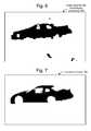
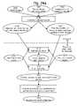
- FIG. 1depicts a live event in which objects are tracked by cameras.
- FIG. 2depicts a video image which includes a race car as a tracked object.
- FIG. 3depicts a portion of the video image of FIG. 2 as a pixel template.
- FIG. 4depicts an image showing vertical edges of the object of FIG. 2 .
- FIG. 5depicts an image showing horizontal edges of the object of FIG. 2 .
- FIG. 6depicts an image formed by combining horizontal edges of FIG. 5 which are near the vertical edges of FIG. 4 , and performing morphological processing on the combined image.
- FIG. 7depicts a template formed by a model of the object.
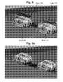
- FIG. 8depicts a video image showing objects and mesh models which are offset from one another.
- FIG. 9 adepicts the video image of FIG. 8 after correcting the offset.
- FIG. 9 bdepicts the video image of FIG. 9 a with added graphics.
- FIG. 10depicts a video image showing objects and textured models which are offset from one another.
- FIG. 11depicts the video image of FIG. 10 after correcting the offset.
- FIG. 12depicts a relationship between camera, image and world coordinate systems.
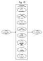
- FIG. 13depicts an overview of a system for modifying video data.
- FIG. 14 adepicts a process for detecting a representation of an object in an image using a template.
- FIG. 14 bdepicts a process for updating camera registration and/or sensor data.
- FIG. 14 cdepicts a process for updating location data.
- FIG. 15 adepicts processing of offset data using past and/or future images.
- FIG. 15 bdepicts a process for determining whether to add a graphic to video based on quality metric.
- FIG. 16depicts a process for detecting a representation of an object in an image via edge and morphology based template matching.
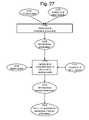
- FIG. 17depicts a process for detecting a representation of an object in an image using a template formed from video data of a prior image.
- FIG. 18depicts a process for detecting a representation of an object in an image using multiple templates.
- FIG. 19depicts a process for detecting a representation of an object in an image using templates indexed to location and/or camera sensor data.
- FIG. 20depicts a process for storing camera registration-related data indexed to location and/or camera sensor data.
- FIG. 21depicts a process for determining a search area for detecting a representation of an object in an image using camera registration-related data indexed to location and/or camera sensor data.
- FIG. 22 adepicts a color profile
- FIG. 22 bdepicts a process for storing color profiles of known objects.
- FIG. 23depicts a process for using stored color profiles to identify an unknown object.
- FIG. 24 adepicts an overview of a system for providing fluid flow data.
- FIG. 24 bdepicts a process for obtaining fluid flow data before an event.
- FIG. 24 cdepicts a process for obtaining fluid flow data during an event.
- FIG. 25depicts an image showing fluid flow graphics.
- FIG. 26depicts an image having a graphic which depicts fluid flow forces.
- FIG. 27depicts an overview of a system for providing aerodynamic forces/parameters.
- FIG. 28 adepicts a process for obtaining aerodynamic parameters before an event.
- FIG. 28 bdepicts a process for obtaining aerodynamic forces/parameters data during an event.
- FIG. 29depicts camera, processing facility and on board object components for implementing the techniques discussed herein.
- the present inventionprovides a system and method for processing image data of a live event.
- FIG. 1depicts a live event in which objects are tracked by cameras and GPS receivers.
- objectssuch as a race cars 102 and 104 traverse a course at an event facility 100 such as a race track.
- an event facility 100such as a race track.
- the objectsmay be humans or animals.
- the objectcan be a ball or other game object in a sporting event.
- the objectsmay travel on the ground, on water, under water or in the air.
- the event facility 100includes a race course or track 101 on which the objects 102 and 104 travel.
- Two objectsare depicted as an example only, as one or more objects may be present. Further, the object may be stationary or moving.
- One or more camerasare positioned to capture images of the object.
- cameras 110 , 112 , 114 and 116are located at different positions along the course.
- the camerascan follow the objects as they travel along the course.
- the arrangement of cameras shownis an example only. Other views, including overhead views, views from the grandstands and so forth can also be provided. Moving; and on-board cameras can also be used.
- the cameras 110 , 112 , 114 and 116can be television broadcast cameras, for instance, which capture thirty frames or sixty fields per second, in one possible approach.
- HD-SDI 720p videouses 60 frames/sec. While such cameras sense visible light, it is also possible to use cameras that sense electromagnetic radiation outside a range of visible light, such as infrared radiation, depending on the application. Further, note that other rates of image capture can be used.
- the location of the objectscan be described in terms of a world coordinate system 130 , also known as a free space coordinate system, which is fixed relative to the earth or other environment of interest, in one approach.
- the world coordinate system 130includes orthogonal directions represented by a wy axis, a wx axis, and a wz axis which extends out of the page.
- An origin of the world coordinate systemcan be chosen to be at a specified location relative to the event facility 100 . Or, the origin can be miles away from the event.
- Other world coordinate systemswhose axes are not orthogonal are also possible, including for example coordinate systems which use latitude, longitude and elevation, spherical coordinate systems and so forth.
- Each cameracan be provided with sensors which detect intrinsic and extrinsic parameters of the camera when these parameters are variable.
- Intrinsic parameterssuch as focal length lens distortion and zoom setting represent characteristics of the camera design and settings, and do not depend on the position and orientation of the camera in space.
- Extrinsic parameterssuch as tilt or pan, depend on the position and orientation of the camera in space.
- sensorscan be provided using, techniques known to those skilled in the art. For example, pan and tilt sensors can be attached to a tripod on which the camera is mounted. See, e.g., U.S. Pat. No. 5,912,700, issued Jun. 15, 1999, incorporated herein by reference.
- the sensorscan be used to determine the field of view of the camera, e.g., where the camera is pointing and what it can see.
- a computer using optical recognition technologycan find the mark in the video frame and, based on the mark's size and position in the video frame, determine the camera parameters.
- Another approach to determining intrinsic and extrinsic parameters of a camerainvolves placing marks in various measured or known locations in the event facility such that each mark looks different, but the marks may be removed after camera parameters have been determined.
- a computer implementing a camera parameter estimation algorithm based on manual user interaction rather than, or in addition to, pattern recognitioncan determine camera parameters.
- the camerascapture images of the objects and communicate the images in analog or digital signals by wire or other link to a processing facility 140 , which can be a mobile facility parked at or near the event facility 100 , in one possible approach.
- the processing facility 140includes equipment which receives and stores the captured images, and processes the captured images, such as to add graphics to the images.
- the processing facility 140can enhance the video signals based at least in part on the determined position of the object.
- Example enhancementsinclude a graphic which provides an identifier for the object, such as an identifier of the driver of the car, an advertisement or other logo which is overlaid on the object, a graphic which depicts air or other fluid flow over the object and a graphic which depicts aerodynamic or other forces on the object.
- the processing facility 140can subsequently transmit the enhanced video, via an antenna 145 or optical fiber, etc., to another location such as a television broadcast facility for broadcast to viewers in their homes. In another approach, the processing facility can be remote from the event facility 100 . Enhancement of the images could also be performed in a studio or even at the viewer's home, e.g., via a set top box.
- imagescan similarly be communicated to end users via a network such as the Internet, or a cell phone network, to computing devices such desktop computers, laptops, cell phones with image rendering capabilities, portable digital assistants and the like.
- the imagesare streamed to a computing device.
- the imagescan similarly be downloaded as one or more files from a server. It is also possible to transmit the enhancement (or data to compute the enhancement) via a separate mechanism or channel from that which transmits the video “program”.
- GPSGlobal System for Mobile Communications
- FIG. 1A GPS satellite 106 is depicted in FIG. 1 as an example.
- a GPS receiverwhich is carried on board the object (see also FIG. 29 ) receives the GPS signals and determines the receiver's position. The receiver's position can then be relayed to the processing facility 140 or other location via a wireless radio (RF) signal.
- RFwireless radio
- a GPS antenna for an objectsuch as a car is carried on the roof of the car. It is also possible for an object to use multiple GPS antennas, which can enable the determination or object orientation as well.
- GPScan provide a location accuracy to within about 2 cm in ideal situations.
- the accuracycan be affected, e.g., due to weather conditions, obstructions in the line of sight from the receiver to a satellite, such as buildings or hills, service problems with a satellite and so forth.
- the objectcan carry a receiver which receives radio signals from local ground based antennas, e.g., antennas 120 , 122 and 124 .
- the receivercan then determine its location through multi-angulation and/or multi-lateration, signal strength, carrier phase, and so forth.
- One form of multi-angulationis triangulation
- one form of multi-laterationis trilateration.
- the objectcan also communicate its position via telemetry to the processing facility 140 or other location.
- the position of the objectcan be extrapolated and/or interpolated based on the expected behavior of the object. For example, assuming the object is a vehicle traveling on repeated circuits of a race course, every time the car crosses the start/finish line or other predetermined location, a signal can be generated from a timing and scoring system. For example, the signal can be generated using technology which is similar to the loops that are used in a road to control a traffic signal by indicating that a car is at an intersection. Such technology is available from AMB i.t. of Haarlem, The Netherlands.
- the position of the carcan be extrapolated by measuring the time period from the last loop crossing. This could also be done using IMU data.
- the object's locationcan be determined based on a time and/or distance since the object passed a known location in the live event.
- the cartransmits a radio or other electromagnetic signal which is detected by sensors around the race course. The position of the car at a given time can therefore be determined based on when the sensors detect the signal, of where they resolve the signals in their field of view, carrier phase or the like.
- an optical signalis used to determine a location of the object.
- the time/distance unit 2988 of FIG. 29can be used to provide time and/or distance data as discussed herein.
- FIG. 2depicts a video image which includes a race car as a tracked object.
- the video image 200includes a race car object 220 and a portion of another race car.
- a video imagecan include one or more objects.
- a single objectcan be detected among other objects in an image if a sufficient portion of the object is visible. This will vary in different situations. Further, factors such as lighting, visibility, e.g., due to rain or dust, object speed, camera resolution, how fast the camera is panning, and the like will also impact the ability to detect a given object.
- a search area 210is also depicted in the video image 200 . As described further below, various techniques can be used to determine an appropriate search area for identifying an object in an image.
- an estimate of the position of the object in the race or other live event, along with knowledge of the camera's pose,can be used to determine an estimated position of the object in the corresponding image.
- a bounding box 215can be defined which has a size in pixel space which bounds an estimated size of a representation of the object in the image.
- the search area 210extends a specified number of pixels around the bounding box, e.g., above, below, to the right and to the left. In one approach, the search area is centered on the bounding box. Factors such as the direction of motion of the object, camera sensor data, e.g., pan, tilt and zoom, the aspect ratio of the image and knowledge of location system inaccuracies, can also be used to set the size, shape and location of the search area.
- the bounding box 215does not exactly bound the representation of the object 220 , but is offset.
- This offsetcan be caused, e.g., by inaccuracies in the camera registration and/or sensor data, and/or inaccuracies in the location data which indicates a location of the object in the live event.
- the position and size of the bounding box 215is based on an orientation of the object and a transformation function which transforms the object, with its given orientation, from the world coordinates of the live event to pixel coordinates of the video image.
- the transformationuses both camera registration data and camera sensor data.
- the transformationcan include both distortion correction and a projective transformation, which are non-linear.
- Registration datagenerally refers to the calibration of the camera sensors and some physical properties of the camera.
- registration datacan include pan offset, tilt offset, zoom field of view map, camera position (x, y, z), lens distortion and focus. These parameters are normally measured once per installation. Although, in one implementation, focus readings are taken thirty times per second.
- Camera sensor datacan include time varying pan, tilt, zoom, and focus data. These data are all subject to inaccuracies. For example, a camera may be registered to a high degree of accuracy, but wind, vibration or other conditions can cause movement of the camera directly or via a platform on which it is mounted.
- the accuracy with which the position of the object in the image can be determinedis reduced.
- processing delays and inaccuraciescan be problematic.
- Techniquesare provided herein to increase the accuracy with which the position of an object in an image is calculated. Predetermined colors and/or patterns may be used to identify an object as well as to uniquely distinguish one object from an otherwise similar object.
- FIG. 3depicts a portion of the video image of FIG. 2 as a pixel template.
- the templatecan be static or can include a number of still frames which are not from video or a number of video frames.
- the pixel data which represents the objectcan be stored as a template 300 for use in detecting the object in a subsequent image.
- the templateis a rectangular portion of the image which includes the object.
- the templatecan be approximately the same size as the bounding box.
- the templatecan be large enough to encompass the outer boundaries of the entire object, in one approach, or the outer boundaries of a significant portion of the object, for instance.
- the templateneed not be rectangular but can conform to the shape of the object, for instance.
- the templatecan be determined automatically from the detected position of an object in an image by selecting a predetermined number of pixels to the left, right, above and below the position or according to some other pattern which is defined relative to the position of the object.
- FIG. 4depicts an image showing vertical edges of the object of FIG. 2 .
- Pattern recognition techniquesinclude edge detection which involves detecting edges of objects in an image. The edges can be detected based on contrasts in pixel data which extend generally vertically in an image or otherwise along a specific direction. Edge detection can be performed using luminance and/or chrominance pixel data from an image. The chrominance pixel data can encompass any desired color space, including monochrome. RGB, YUV and HSV, among others, for instance. These edges need not represent physical features of the object, but may represent “edges” within patterns painted on the object, for example.
- edge detectioncan be performed relative to any given orientation in an image.
- edge detectionmay occur relative to a direction of motion of an object, e.g., parallel and/or perpendicular to the direction.
- the direction of motionis typically horizontal across the frames as many camera shots involve panning. It is noted that while the cars generally move horizontally, their images can move at any angle, including vertically, within a video frame.
- the direction of motion of an objectcan be assumed based on knowledge of the camera's position and movements and the path of the object being tracked. Or, the direction of motion can be determined based on sensor data of the camera, e.g., indicating pan, tilt and zoom.
- the panning direction of the cameracan indicate the direction of motion.
- a cameracan be instrumented with sensors which detect such information.
- the direction of motioncan be determined based on position differentials, e.g., the change in the position of an object over time.
- the change in the location of an object as measured by, e.g., a GPS receiver on board the object, along with camera parameterscan be used to determine the direction of motion.
- Performing edge detection in a direction which is perpendicular to the direction of motion in the imagecan be advantageous in distinguishing edges of a moving object because the background objects will have motion blur perpendicular to the direction of motion.
- the blurred edges of the perpendicular background objectswill not have a sharp edge. It is difficult to distinguish edges of the moving object from the edges in the background objects which are parallel to the direction of motion because the background object edges are not blurred and are thus indistinguishable from the edges of the desired moving object.
- the background objectscan include the race track surface, walls, grandstands, poles, building and so forth.
- the bottom portion of FIG. 2depicts an example of motion blur caused by stationary objects in the foreground.
- the video imagescan be processed at the processing facility 140 by analyzing the pixel data in each image. This processing can occur in real time as each image is received. Real time processing can include, e.g., processing that occurs during a video broadcast of a live event.
- the image of FIG. 4represents detected vertical edges 400 . Note that the images of FIGS. 4-7 need not actually be rendered on screen but are provided to indicate how the original image is processed.
- the data which is represented by the imagescan exist solely in memory. As can be seen, most of the detected edges are part of the object, e.g., the car, while some stray vertical edges are detected as well.
- FIG. 5depicts an image showing horizontal edges of the object of FIG. 2 .
- Horizontal edge detectioncan be performed in additional to vertical edge detection.
- edge detection which is parallel to the direction of motioncan be performed in addition to edge detection which is perpendicular to the direction of motion.
- motion blurresults in edges of the object and edges outside the object being detected parallel to the direction of motion. The blur occurs in the primary direction of motion, but it mostly affects edges that are perpendicular to that direction.
- the video imagescan be processed at the processing facility 140 by analyzing the pixel data in each image. This processing can occur in real time as each image is received.
- the image of FIG. 5represents horizontal edge components 500 .
- the detected edgesinclude edges which are part of the object, e.g., the car, as well as many stray horizontal edges which are part of the background and/or foreground environment of the object.
- FIG. 6depicts an image formed by combining horizontal edges of FIG. 5 which are near the vertical edges of FIG. 4 , and performing morphological processing on the combined image.
- Morphological processingis one image processing technique which can be used to detect a representation of an object in an image.
- the image data of the vertical and horizontal edgesis represented as a binary image, in which each pixel is restricted to a value of either 0 or 1.
- Each pixel in the backgroundis displayed as white, while each pixel in the object is displayed as black.
- Binary imagescan be formed, e.g., by thresholding a grayscale image such that pixels with a value greater than a threshold are set to 1, while pixels with a value below the threshold are set to 0.
- the image datacan be processed using two basic morphological operations, namely dilation and erosion. Further, one could repeat this process for different color components of the object. And of course it is not necessary that each pixel be restricted to a value of 0 or 1, or that it even be monochrome in nature.
- Every object pixel that is touching a background pixelis changed into a background pixel.
- dilationevery background pixel that is touching an object pixel is changed into an object pixel.
- Erosionmakes an object smaller, and can break a single object into multiple objects. Dilation makes an object larger, and can merge multiple objects into one. Opening is defined as an erosion followed by a dilation. Closing is the opposite operation and is defined as a dilation followed by an erosion. Opening tends to removes small islands and thin filaments of object pixels, while closing tends to removes islands and thin filaments of background pixels.
- first edgese.g., vertical edges or edges which are perpendicular to the direction of motion
- second edgese.g., horizontal edges or edges which are parallel to the direction of motion, and which intersect the dilated first edges
- the second edges which do not intersect the dilated first edgesare discarded.
- the second edges which are near the dilated first edgese.g., a specified number of pixels away, can also be selected.
- Additional morphological processingcan be performed to obtain data which is depicted by the image 600 . This depiction provides a rough outline of the object, or features of the object, in addition to some noise.
- morphological processingis discussed as an example, many image processing techniques can be used to detect the representation of an object in an image.
- FIG. 7depicts a template formed by a model of the object.
- the templateis also formed using knowledge of its orientation and location, as well as knowledge of the camera pose at the time the image is taken.
- the image of FIG. 6can be processed by comparing it to a template of the object.
- a template 700can be provided based on a shape and orientation of the object, in addition to an estimated size of the representation of the object in the image.
- the objectcan be a car with a known shape which is modeled as a 3d mathematical model. See also FIG. 8 , which depicts mesh models 802 and 812 of cars.
- the orientation of the objectcan be determined based on an inertial measurement unit (IMU) carried on board the object.
- IMUinertial measurement unit
- the IMUcan include gyroscopes which provide heading, pitch and/or roll information. Heading can also be determined using position differentials at different times. For example, if an object is in position P 1 (x 1 , y 1 , z 1 ) at time t 1 and in position P 2 (x 2 , y 2 , z 2 ) at time t 2 , the heading at a time which is halfway between t 1 and t 2 can be computed as the vector P 2 ⁇ P 1 . Or, a model of the track that the object is traversing can be used to determine the orientation. The roll orientation, for example, can be computed based on a track normal at the location of the object.
- location data of the object in the live eventcan indicate where the object is relative to the track. It can then be assumed that the object has a particular orientation based on that location, e.g., the object has a heading which is in the direction of the track at the location, has a roll angle which is the bank angle of the track at the location, and has a pitch angle which is the pitch of the track at the location.
- this informationmay be used with information from other source to determine the object's orientation. It is also possible to perform rotating, skewing, and scaling captured templates to match the object in its predicted location and orientation.
- the estimated size of the representation of the object in the imagecan be determined based on, e.g., sensor data of the camera, such as a zoom setting of the camera, and a known distance from the camera to the object.
- sensor data of the camerasuch as a zoom setting of the camera
- the distance from a fixed camera position to the objectcan be calculated for different locations of the track, and location data of the object can be used to determine the distance.
- the camera and objectboth include location-detecting devices such as GPS receivers, and the distance between the camera and the object is based on a difference between their relative locations.
- the template 700is compared to the image 600 at each (sx, sy) pixel location in the search area. See also FIG. 12 regarding coordinates in pixel space.
- the image 600 and template 700are both binary images.
- a cross-correlation between the image and templatecan be determined for each relation between template and image. This may include scale, rotation, skewing, distorting either the template, the image or both.
- the position of an optimum representation of the object in the imagecan be determined based on the closest correlation, or a combination of correlation and expected location/orientation of the object based oil other matching methods, vehicle and camera behavior, vehicle location system, etc.
- the video template 300 of FIG. 3can be correlated with each different location in the search area 210 of FIG. 2 to determine the position of an optimum representation of the object in the image based on the closest correlation.
- the video templatemay be obtained, e.g., using edge and morphology based template matching, as described previously.
- the correlationcan be made using luminance and/or chrominance data (in any color space). Further, multiple correlations can be made, each using a different color space or different color components, and the results combined.
- multiple detecting techniquescan be used and the results can be merged or compared to obtain a final result regarding the position of an object in an image. This would typically be done to make the most of each technique's strengths while avoiding each technique's weaknesses. For example one technique might be extremely accurate, but a poor discriminator of matches to the wrong, object, while another technique may be less accurate while providing good discrimination.
- comparison of the morphological image 600 to a template of a model of the object 700can be performed to obtain a first determination of a position of the object in the image
- comparison of the pixel data of a video template 300 to video data 200 of the objectcan be performed to obtain a second determination of a position of the object in the image.
- the determined positionsmay differ.
- One approachis to determine a final position which is between the determined positions. For example, assume first and second object detection techniques result in image position x 1 , sy 1 ) and (sx 2 , sy 2 ), respectively.
- a final object position in pixel spaceis then (0.5 ⁇ (sx 1 +sx 2 ), 0.5 ⁇ (sy 1 +sy 2 )).
- weightscan be assigned to the respective positions so that one position is accorded a greater weight if it is obtained by a technique that is deemed more reliable, for instance.
- a final object positionis (0.25 ⁇ sx 1 +0.75 ⁇ sx 2 , 0.25 ⁇ sy 1 +0.75 ⁇ sy 2 ).
- the object positioncan be defined at the center of the object or at another reference location on the object.
- voting schemesalso offer certain advantages.
- Another possible weighting schemeis as follows. In a first step, detect the screen position (sx, sy) based on video template matching or other first type of template matching. In a second step, detect the following set of possible screen positions based on edge/morphology based template matching or other second type of template matching: (sx 1 , sy 1 ), (sx 2 , sy 2 ), (sx 3 , sy 3 ) . . . Each one of these screen positions was detected with a certain correlation, e.g., c 1 , c 2 , c 3 . . .
- a third stepamong the positions detected in the second step, pick the one that is close to the position detected in the first step and at the same time has a good correlation (e.g., a correlation which exceeds a threshold).
- the following weighting functionmay be used to achieve this: W 1 *correlation+w 2 *(1 ⁇ dist/maxdist), where dist is the Euclidean distance between a position detected in the second step and the position detected in the first step, maxdist is the maximum of such distances computed.
- multiple detectionscan be performed using a given technique and an average, mean or other statistical metric used to determine the final position.
- a statistical metric based on detections using multiple techniquescan also be used.
- Positions which are outlierscan be omitted using signal processing techniques.
- signal processing techniquescan be used to remove noise and random errors, and to omit results which are inconsistent with physical constraints of the object, environment of the object, such as a race track, and/or the at least one camera.
- the (sx, sy) image positions detected for an object in a sequence of consecutive frames( 100 , 150 ), ( 110 , 152 ), ( 210 , 154 ), ( 130 , 156 ), ( 140 , 157 ), using signal processing we can detect and remove the position ( 210 , 154 ) as outliner since the change in image positions of the object corresponds to a change in the object's locations in the live event which is not physically possible for the object.
- Techniques for detecting an objectcan be applied as well to detecting multiple objects. Tracking multiple objects in parallel can be performed, where the matching results of one object can be used to refine an initial estimate for the other objects, such as an estimate of positions of the representations of the other objects in an image. Further, the detection of one or more objects can occur repeatedly, once for each image in a series of images such as a video broadcast.
- the template 700 and other templates discussed hereincan be generated on the fly for each tracked object.
- the detected location of an object in an imagecan differ from the expected location as determined by location data from GPS or other initial estimation techniques discussed herein. Inaccuracies which can be observed are illustrated below.
- FIG. 8depicts a video image showing objects and mesh models which are offset from one another.
- the imageincludes objects 800 and 810 and models 802 and 812 , respectively which are overlaid on the image at the respective expected locations.
- An offset or offsets between the models and the objectsis clearly seen.
- a model or other graphiccan also be provided on a new image which is derived from the original image.
- FIG. 9 adepicts the video image of FIG. 8 after correcting the offset.
- the modelsare overlaid on the image at the detected locations of the objects in the image.
- the modelscan have a shape and appearance which is specific to the object which it models.
- FIG. 9 bdepicts the video image of FIG. 9 a with added graphics.
- graphicscan be combined with the pixel data of a video image to provide a combined image as discussed below.
- the graphicsinclude a graphic 900 which is a logo or advertisement which is overlaid on the object.
- the mesh modelis also depicted for reference, but it is not necessary to display the model, as the logo or advertisement can be overlaid directly on, or otherwise combined with, the video image of the object.
- the modelis used to define the location and appearance of the logo so that it appears more realistic, as if it is actually painted on the object, or in the case of pointers, that it accurately points to the appropriate object. If the logo was to be inserted into the image based on the location data-based position rather than the detected position, it would likely not be positioned correctly and would not appear as if it was part of the live event.
- pointersare intended to be accurate, but are not intended to appear as if they are a part of the live event.
- graphicssuch as airflow graphics are intended to appear as if they were part of the live event, but unlike a logo, are not intended to give the illusion that they actually are part of the live event
- Graphics 910 and 920identify the objects based on the car number and the driver's name. These graphic include pointers which extend to the objects in the image. Again, detecting the actual position (and scale, orientation, etc.) of the objects in the image allows these graphics to be correctly positioned.
- the location data of the objectincludes an identifier of the object which is used in the identifying graphics 910 and 920 .
- Such graphicsallow a television broadcast of a live event to be enhanced by providing information which allows the viewer to follow and learn about the event and can enable the broadcaster to call attention to specific objects or players the announcers/talent may wish to discuss.
- FIG. 10depicts a video image showing objects and “textured” models which are offset from one another.
- the texturedoes not necessarily imply a physical relief in this context.
- the models of the objectscan have a texture or skin which mimics that of the real object.
- models 1002 and 1012mimic the appearance of real objects 1000 and 1010 , respectively.
- FIG. 10depicts the models when they are offset due to inaccuracies.
- FIG. 11depicts the video image of FIG. 10 after correcting the offset.
- Information regarding the paint scheme of each objectsuch as cars in a race, can be combined with knowledge of the shape of each object to provide the models depicted using known modeling and rendering techniques.
- the average offsetas a camera registration error while the relative offsets of the models 1002 and 1012 are assumed to be positional errors, for example.
- the texture of the modelscan include color in a “pattern” sense as well as a “color content” sense.
- the models with the texture appliedcan also be used as templates in a correlation process as discussed in connection with FIG. 18 .
- FIG. 18describes a combination algorithm which uses model/edge based matching and video template based matching.
- the textured model templateneed not necessarily be used in this combination algorithm. It can be used by itself.
- the model rendered with texturecan be used as a template to match/correlate with the video directly.
- a broadcast of a racecan be enhanced by overlaying a model of a car over the video image, e.g., to highlight a car that is leading the race or is otherwise of interest.
- the modelscan be blended in and out seamlessly to provide a continuous viewing experience.
- other eventscan be enhanced by the addition of graphics which are located accurately with respect to objects in images, and which provide information which is specific to the objects.
- FIG. 12depicts a relationship between camera, image and world coordinate systems.
- a camera coordinate system 1210which includes orthogonal axes X C , Y C and Z C in three dimensions, is fixed relative to the camera. The origin of the coordinate system may be at the front nodal point of the lens, in one possible approach, modeling the camera as a pinhole camera.
- An image coordinate system 1220also referred to as pixel space, includes orthogonal axes X and Y in two-dimensions, and is fixed relative to a captured image 1200 .
- a world coordinate system 1230which includes orthogonal axes X W , Y W and Z W , is fixed relative to, e.g., the earth, the site of a live event such as a stadium, or other reference point or location.
- the position and/or path of the object 1240can be determined in the world coordinate system 1230 in one possible approach, e.g., using GPS data or other approaches.
- the line of position 1212is an imaginary line which extends from the camera position (which in this case is at the origin of the camera coordinate system 1210 ) through a pixel in the image 1200 , intersecting the pixel at a point 1225 , and through the object 1240 . Each pixel in the image 1200 corresponds to a different line of position.
- Point 1225 in the captured image 1200represents the location of the object 1240 in the image.
- the location of the object in the image 1200can be represented by coordinates (sx, sy) in a coordinate system which has its origin at a corner of the image, in one approach.
- the coordinatesmay identify the center of the object.
- the line of positioncan be represented by a vector (LOP) which has unity magnitude, in one approach.
- LOPvector
- the vectorcan be defined by two points along the LOP.
- the vectorcan be represented in the world coordinate system 1230 using an appropriate transformation from the image coordinate system.
- the Z C axis of the camera coordinate systemwhich is the optical axis 1214 of the camera, intersects the captured image at a point represented by coordinates (0 x , 0y).
- a two-dimensional coordinate system extending from (0 x , 0 y )can also be defined.
- the camera registration processinvolves obtaining one or more transformation matrices or functions which provide a conversion between the image coordinate system 1220 and the world coordinate system 1230 . Further information can be found in E. Trucco and A. Verri, “Introductory techniques for 3-D computer vision,” chapter 6, Prentice Hall, 1998, U.S. Pat. No. 5,912,700, issued Jun. 15, 1999, and U.S. Pat. No. 6,133,946, issued Oct. 17, 2000, each of which is incorporated herein by reference.
- a location of an object at a live eventcan be transformed to a position, orientation, etc. in the image, and search parameters for detecting the object can be defined based on this position.
- Search parameterscan encompass a search area as well as other information for searching.
- the detected location, orientation, scale, etc., of an object in an imagecan be used to correct location data and camera registration and/or sensor data as described herein.
- FIG. 13depicts an overview of a system for modifying video data.
- the systemis depicted in a conceptual overview as including a number of processing components 1300 which act on input video data 1310 to provide output video data 1328 .
- the input video datacan be obtained, e.g., from a broadcast of a live event, from delayed video of the live event, or from a replay during or after the live event.
- the processing componentscan include different types of information, including object orientation 1312 , object position 1314 , object shape 1316 , a track model 1318 for an object which moves on a track, camera sensor data 1320 , camera registration data 1322 , graphics 1324 and a fluid flow model 1326 .
- the processing componentscan be provided to the processing facility 140 for use in providing graphics or other enhancements in the output video data 1328 .
- Some of the processing componentsare predetermined/precomputed before images of an event are obtained. These can include, e.g., object shape, track model, initial camera registration data, graphics and fluid flow model. Some of the processing components can be obtained or updated during an event, such as object orientation, object position, camera sensor data and inputs to the fluid flow model. Further information regarding the processing components is provided below. Further information regarding the fluid flow model 1326 is provided in connection with FIGS. 24-28 .
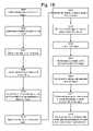
- FIG. 14 adepicts a process for detecting a representation of an object in an image using a template.
- the position of a representation of an object in an imagecan be determined through correlation with a template of the object.
- the templatecan include a binary image of the object which is obtained from edge and morphology based template matching (see also FIG. 16 ) and/or a video template which includes pixel data of the object from a prior image. Multiple detection techniques can also be used and the results combined.
- An example processincludes, at step 1400 , determining the orientation of an object such as based on an inertial measurement unit carried by the object, a track model and/or position differentials at different times, as discussed previously in connection with FIG. 1 . Note that the orientation data need not be updated as quickly as a typical video frame rate as it typically does not change that quickly.
- Step 1402includes determining the location of the object in the live event, e.g., based on GPS or other location data.
- Step 1404includes obtaining camera registration data.
- Step 1406includes determining an estimated size, orientation and position of the object in the image. This can be achieved, e.g., by transforming the size, orientation and position of the object in the live event from world coordinates to image coordinates using a transformation matrix which is based on the camera registration and sensor data.
- Step 1408includes determining a set of search parameters (e.g., a search area) for the object, as discussed previously in connection with FIG. 2 .
- Step 1410includes defining a template based on the estimated size, orientation and position (distortion, perspective, etc.) of the object in the image.
- Step 1412includes searching for a representation of the object in the image, e.g., in the search area, by correlation with the template. Once the position, orientation, etc. of the representation of the object in the image is determined, it can be stored for subsequent use and/or reported, e.g., via a user interface, printer or other output device. The position can also be used for providing graphics in the image and/or for updating camera registration and/or sensor data (step 1414 ) and/or updating location data (step 1416 ). This applies also to any of the other approaches discussed herein for detecting a representation of an object in an image.
- camera registration and sensor dataare subject to inaccuracies due to, e.g., wind, vibration or other conditions that can cause movement of the camera. Inaccuracies in camera registration data can also occur due to inaccuracies in the position of registration marks in the event facility, inaccuracies in determining the camera location and so forth.
- By updating the camera registration and/or sensor data for many or all frames based on the detected position of an objectthese inaccuracies can be compensated.
- the camera registration and/or sensor data for a given framecan be refined using the updated camera registration and/or sensor data from a prior frame so that the data is continuously refined from image to image.
- one approachinvolves updating registration data of a camera based on the position of the representation of an object in an image.
- Another approachinvolves updating sensor data of a camera based on the position of the representation of an object in an image.
- Another approachis to compute a new transformation matrix or function based on the position of the representation of an object in an image.
- the transformation matrix or functioncan provide a conversion between an image coordinate system and a world coordinate system, or between an uncorrected image coordinate system and a corrected image coordinate system, or otherwise between different image coordinate systems, for instance.
- location data of the object in the live eventsuch as from a GPS receiver
- location data of the object in the live eventis subject to inaccuracies.
- a transformation of an object location from world coordinates to image coordinatesmay not align with the video image of the object due to such inaccuracies.
- One approach to determining whether the camera data or the location data is incorrectis to observe the expected locations of multiple objects in an image based on their location data relative to their actual locations in an image and relative to reference locations in the image, such as the wall at the edge of a race track. If the expected locations of all of the objects are offset by a certain amount in a similar way, this indicates the inaccuracy is likely due to the camera registration and/or sensor data. For example, FIG.
- FIG. 8depicts how models 802 and 812 are offset similarly from objects 800 and 810 , respectively. If the expected locations of some of the objects are offset by a certain amount in a similar way while the expected locations of other objects are offset by a different amount, this indicates the inaccuracy is likely due to the location data of the offset objects.
- a human operatorcan observe the images with the overlaid models to make this determination, or this process can be automated. Moreover, tracking of a stationary object such as a wall or pole will give a better sense of registration inaccuracies compared to tracking a moving object. Once it is determined that an inaccuracy is caused by the location data of a particular object, an appropriate update can be applied to the location data of that object for the current image and/or subsequent images.
- FIG. 14 bdepicts a process for updating camera registration and/or sensor data (step 1420 ).
- Step 1422includes determining camera registration and/or sensor data which corresponds to the detected position of an object in an image.
- Step 1424includes determining an offset to the camera registration and/or sensor data based on an offset between the detected position of the object in the image and a position of the object in the image which is based on the location data.
- the offsetmay be expressed in image space as ( ⁇ sx, ⁇ sy), for instance. Further, the offset in pixel space may be converted to registration data adjustments, and pan and tilt offsets, for example.
- Step 1426includes applying the offset to camera registration and/or sensor data for a next image.
- new camera registration and/or sensor datacan be determined outright based on the detected position of the object in the image, and this new data can be used for the current and/or subsequent images. The process can be repeated for each successive image.
- FIG. 14 cdepicts a process for updating location data (step 1430 ).
- Step 1432includes transforming the detected position of the object in the image from pixel space to an updated location in world coordinates.
- Step 1434includes determining an offset in world coordinates between the original location and the updated location. The offset may be expressed as a 3d vector in world coordinates, for instance.
- Step 1436includes applying the offset to location data for the current and/or subsequent image. The process can be repeated for each successive image.
- the steps depictedneed not occur as discrete steps and/or in the sequences depicted. Further, the detection of one or more objects can occur repeatedly, once for each image in a series of images such as a video broadcast.
- FIG. 15 adepicts processing of offset data using past and/or future images.
- the offset or inaccuracy between the expected position of an object in an image based on location data of the object and the detected position of the object in the imagecan be determined for successive images. Further, the offset for a given image can be processed based on the offset from past and/or future images. Appropriate buffering or delay techniques can be used. For example, at times, the car or other object can be obscured by objects around the track (e.g., buildings, fences, motorhomes, flags, etc). When this happens, the correlation between the template and image is poor and can result in a match. i.e., a detected object position in the image, that is not correct.
- This problemcan be addresses by storing the (sx, sy) image offset between the object in image space and where the matching algorithm finds a match, for successive images. This offset tends to move slowly as the car progresses around the track. We can also look into the future by processing every frame of video, but reporting a final result several frames behind. Thus we can evaluate the (sx, sy) offsets of matches in the past as well as (sx, sy) offsets of matches in the future. In the process of reporting the final result of the detected position of the object in an image, we can run a median filter on, the sx, sy offset over successive images. This tends to remove outlying answers that are erroneous when the object is obscured.
- Step 1502includes filtering the offset for image n based, on offsets for past images n ⁇ 2 and n ⁇ 1 and subsequent images n+1 and n+2. In this example, two previous images and two subsequent images are used for filtering, although this can vary.
- Step 1504includes reporting a final offset result for image n based on the filtering.
- FIG. 15 bdepicts a process for determining whether to add a graphic to video based on quality metric.
- one or more templatecan be correlated with different candidate representations of an object in a search area. The template can be shifted one pixel at a time in horizontal and vertical directions and a cross-correlation performed at each position.
- Shifting by sub-pixel amountsis also possible as are scale, skew and rotation operations.
- the position which results in the highest correlation valuecan then be taken as the detected object position, in one approach.
- the correlation value itselfcan be take as a quality metric or associated with a quality metric so that a stronger correlation is associated with a greater quality.
- Best qualitymay also be determined through a combination of best correlation along with other parameters such as expected position or correlations achieved through alternate pattern recognition techniques.
- Step 1510includes correlating a template of an object with candidate representations of the object to select an optimum representation.
- Step 1512includes calculating a quality metric based on the optimum correlation.
- Decision step 1514determines whether the quality is acceptable, e.g., based on whether the quality metric exceeds a threshold. If the quality is not acceptable, the video is broadcast without graphics, at step 1516 . Or, the video can be broadcast using no correction, or using an interpolated or extrapolated correction from corrections to nearby images. If the quality is acceptable, graphics data is combined with pixel data of the image substantially in real time in a video broadcast, in one possible approach, at step 1518 . Finally, step 1520 includes broadcasting the video with the graphics.
- FIG. 16depicts a process for detecting a representation of an object in an image via edge and morphology based template matching.
- Step 1600includes obtaining an image of a live event which include one or more objects which are to be tracked, e.g., detected in the image.
- Step 1602includes determining a corresponding location of the object, e.g., at a time which corresponds to a time the image was captured. Note that location data, as well as other data such as camera sensor data, can be interpolated as it will not necessarily coincide precisely with the image capture time.
- Step 1604includes determining an orientation of the object at the time of the image.
- Step 1606includes obtaining camera registration and sensor data at the time of the image.
- Step 1608includes determining an estimated location, size and orientation (skew, distortion, etc.) of a representation of the object in the image.
- Step 1610includes defining the template based on the estimated location, size and orientation of the object in the image, and defining the search area based on the size and location of the template.
- the templatecan be obtained by rendering a model of the object in the estimated location with the estimated orientation, and the search area can be determined around the rendered model.
- Step 1612includes detecting first edges in the search area which extend in a first direction. The first direction can be perpendicular to a direction of motion: horizontal across the image, or any other direction.
- edge detectionin one or many directions, not just two directions.
- Step 1614includes detecting second edges in the search area which extend in a second direction.
- the second directioncan be perpendicular to the first direction, parallel to the direction of motion, vertical across the image, or any other direction.
- Step 1616includes dilating the first edges and step 1618 includes selecting the second edges which intersect the dilated first edges. Non-intersecting second edges are discarded, in one approach.
- Step 1620includes combining the first edges with the selected second edges, and step 1622 includes performing morphological processing of combined edges to obtain a representation of the object.
- step 1624includes correlating a template of the object with candidate representations of the object in the search area to select an optimum representation.
- FIG. 17depicts a process for detecting a representation of an object in an image using a template formed from video data of a prior image, e.g., prior to the image in which object detection occurs. It is also possible to transform the template in scale, orientation, etc. based on expected appearance—either through interpolation/extrapolation, or through pan, tilt and zoom (PTZ) and position data. See also FIG. 3 , which provides an example of such a template 300 .
- a video templatecan be a composite of video templates in multiple prior images. Also, multiple templates might be used, for example, one for each color component or other processing of the image.
- the templatemay be updated for each current image so that a template from the last prior image is used in the detecting of each current image.
- a given templatemay be used in the detecting of a number of successive images.
- different video templatescan be indexed to object location and/or camera sensor data.
- the video or pixel templatecan include luminance and/or chrominance data, and the chrominance data can be provided in any color space.
- Luminance and chrominanceimply a subset of the color spaces. RGB, for example, doesn't break down into these components, but may also be useful component by component.
- the matching or correlating with the image data in the search areacan generally occur in the same color space, or portion thereof, as the video template. Also, as mentioned previously, and as discussed in connection with FIG. 18 , matching using a video template can be valuable by itself or in conjunction with other matching techniques.
- Step 1700includes obtaining a first image of a live event which includes one or more objects to be tracked.
- Step 1702includes detecting a representation of the object in the first image, e.g., by correlation with a video, binary or other template or via other pattern detection technique. The representation of the object in the first image could also be determined manually by a human operator using an appropriate interface.
- Step 1704includes storing pixel data of the representation of the object as a template for future use. In one approach (see FIG. 3 ), a rectangle which is a portion of the image is stored as the template.
- the templatecan be stored in a volatile working memory of a processor and/or a hard disk or other non-volatile storage, for instance.
- Step 1706includes obtaining a second image of the live event which includes the object. For example, this can be the next frame in a video signal.
- Step 1708includes detecting a representation of the object by correlation using the previously-stored template of pixel data.
- Step 1710includes storing pixel data of the representation of the object in the second image as a template for detection in a third image.
- the template obtained from the first imageis no longer used and can be discarded.
- Step 1712includes using the template from the first image for detection in the third image. In this case, no template is obtained from the second image, and the template from the first image is reused in the third image.
- Step 1714includes forming a combined template from the first and second images for detection in the third image.
- the combined templatecan be formed, e.g., by taking an average or other statistical metric of pixel values for corresponding pixel locations in the templates and may involve transforming templates based on expected or measured parameters.
- a third templatecan be constructed using the first and second templates and knowledge of the geometry of the transformation from world coordinates to image coordinates in both cases. For example, textures can be derived from the first template and texture mapped onto a model of the object in proper orientation for the first template. Similarly, textures from the second template can be derived and texture mapped onto the same model of the object in propel orientation for the second template. This can provide texture mapped image data on a greater portion of the model than from a single template. This process can be extended to any number of templates.
- FIG. 18depicts a process for detecting a representation of an object in an image using multiple templates.
- an objectcan be detected in an image using multiple templates.
- a final result which indicates the positioncan be determined based on the results from matching with each template. Further, multiple results can be obtained from the same template to provide a result with greater reliability.
- Step 1800includes obtaining a first image of a live event which includes one or more objects to be tracked.
- Step 1802includes detecting a representation of the object in the image, e.g., by correlation with a video, binary or other template or via other pattern detection technique.
- Step 1804includes storing pixel data of the representation of the object as a first template.
- Step 1806includes obtaining a second image of a live event which includes the one or more objects to be tracked.
- Step 1808includes detecting a first representation of the object in the second image using the first template.
- Step 1810includes detecting a second representation of the object in the second image using a second template, e.g., which is based on a model of the object, configured with an appropriate orientation and size.
- the second templatecan be analogous to the binary template 700 of FIG. 7 .
- the templatecan comprise a model of the object which has a texture that mimics a texture of the object.
- a model of the objectwhich has a texture that mimics a texture of the object.
- Information regarding the paint scheme of each objectsuch as cars in a race, can be combined with knowledge of the shape of each object to provide the models depicted using known modeling techniques such as texture generation and texture mapping.
- Lighting modelscan also be used to set the model texture. For example, when rendering the object model, lighting models and shadow rendering techniques can be used to make the rendered object look more realistic, i.e., look more like the real object in the video.
- the luminance and chrominance data of the modelcan be used as a template.
- the texturecan be a pre-created skin or created on the fly from matched positions in a video of the object, e.g., curing training laps before a race. In other words, the texture can be reconstructed or refined from video data. Further, the textured model template can used alone or in combination with another template as discussed herein in connection with FIG. 18 .
- the detecting of step 1810can be performed over a smaller search area than a larger area used in step 1808 based on the object position detected in step 1808 , e.g., to fine tune the match found in step 1808 .
- the smaller areacan be at least partially within the larger area.
- This approachcan also reset an accumulating error which can occur when a purely pixel template based approach is used from frame to frame and then the next frame and so on.
- Step 1812includes optionally assigning a weight to each result. For example, refer to the weighting, schemes discussed in connection with FIG. 7 .
- Step 1814includes determining a final position of a representation of the object in the image based on the multiple results. Obtaining a final result by merging or comparing results from multiple detecting techniques is discussed further in connection with FIG. 7 .
- FIG. 19depicts a process for detecting a representation of an object in an image using templates indexed to location and/or camera sensor data.
- Object detectioncan be facilitated when the object repeatedly traverses a course since lighting, camera angles and the like tend to be repeated at different locations along the course.
- templates for detecting the objectcan be obtained when the object is at different locations along the course in a first traversal of the course.
- the templatescan be retrieved and used for object detection for images that are obtained when the object is at the different locations along the course.
- the templatescan be stored indexed to location data and/or camera sensor data, which is a proxy for location data.
- a first traversalwhich may be a practice lap of a race
- location data from the objectis recorded periodically, e.g., once per second, or at designated locations around the course, as world coordinates (wx, wy, wz).
- the templatesmay be pixel templates (see FIG. 3 ), for instance, which are obtained from the images which correspond in time to the locations, and stored indexed to the location data, (wx, wy, wz), for each entry.
- the templatescan be edge and morphology based templates, or other types.
- location data of the object which corresponds to each imageis obtained, and the corresponding template is retrieved for each image and used for object detection.
- the location data used for indexing which is closest to the location data obtained in the second traversalmay be selected, in one approach.
- step 1900includes obtaining a first set of images of a live event which includes an object at different locations, e.g., along a course.
- Step 1902includes detecting a representation of the object in each image, which need not be every available image, using any detection technique.
- Step 1904includes storing templates of the representation of the object in each image.
- Step 1906includes indexing the templates to location and/or camera sensor data.
- Step 1908includes obtaining a new image, e.g., as the object traverses the course a second time.
- Step 1910includes determining location and/or camera sensor data for the new image.
- Step 1912includes retrieving the corresponding template
- step 1914includes detecting a representation of the object in the new image using the template. It is also possible to detect a representation of the object in multiple new images using one retrieved template.
- FIG. 20depicts a process for storing camera registration-related data indexed to location and/or camera sensor data.
- updated or new camera registration and/or sensor datacan be provided for each image in a video signal based on the position of a detected object in an image. Further, the updated or new camera registration and/or sensor data from a given image can be used in a next image. In this way, the camera registration and/or sensor data can be continuously refined so that object detection is facilitated and smaller search areas can be used.
- updated or new camera registration and/or sensor datacan be obtained and stored for different locations which an object traverses, e.g., along a race track or other course, during a first traversal of the course.
- the updated or new camera registration and/or sensor datacan be retrieved and used for object detection for images that are obtained when the object is at the different locations along the course.
- the updated or new camera registration and/or sensor datacan be stored indexed to location data and/or camera sensor data which is a proxy for location data.
- location data of the objectis recorded periodically, e.g., once per second, or at designated locations around the course, as world coordinates (wx, wy, wz).
- the updated or new camera registration and/or sensor datais determined and stored indexed to location, (wx, wy, wz), or camera sensor data, for each entry.
- location data or camera sensor datais obtained for each image, and the corresponding updated or new camera registration and/or sensor data is retrieved for each image and used to define a search area for object detection.
- the location data or camera sensor datais used for indexing which is closest to the location data or camera sensor data, respectively, obtained in the second traversal may be selected, in one approach. Or, we can interpolate or build a correction surface model. It is also possible to store updated or new camera registration and/or sensor data from the second traversal for use in the third traversal, and so forth.
- step 2000includes obtaining a first set of images of a live event which includes an object at different locations, e.g., along a course.
- Step 2002includes detecting a representation of the object in each image using any detection technique.
- Step 2004includes determining camera registration-related data for each image, e.g., based on the detected representation of the object in each image.
- the camera registration-related datacan include updates to registration parameters and/or registration parameters themselves.
- Step 2006includes storing the camera registration-related data for each image.
- Step 2008includes indexing the camera registration-related data to location and/or camera sensor data.
- steps 2000 and 2002are not used. Instead, the camera follows the object at different locations in the live event but does not capture images, or the images are captured but not used in detecting the representation of the object in each image.
- FIG. 21depicts a process for determining a search area for detecting a representation of an object in an image using camera registration-related data indexed to location and/or camera sensor data.
- the indexed camera registration-related datacan be used in a subsequent traversal of the course.
- step 2100includes obtaining a new image, e.g., as the object traverses the course a second time.
- Step 2102includes determining location and/or camera sensor data for the new image.
- Step 2104includes retrieving the corresponding camera registration-related data.
- Step 2106includes transforming the location and/or camera sensor data to an estimated position in the new image using the camera registration-related data.
- thiscan include providing a transformation function which is based on the camera registration-related data, and applying the transformation to the location and/or camera sensor data.
- Step 2108includes determining a search area in the new image based on the estimated position of the object in the image. Due to the improved accuracy of the estimated position in the new image which results from the use of the stored camera registration-related data, a smaller search area can be used than if would otherwise be the case.
- step 2110includes detecting a representation of the object in the search area. It is also possible to store new camera registration-related data from the second traversal for use in the third traversal, and so forth.
- FIG. 22 adepicts a color profile.
- a color profile or signatureinvolves a distribution of color data of an image of an object across a color space palette.
- the color profilecan be expressed by a histogram, where each vertical bar indicates, by its height, a number of pixels which have been classified into a particular bin or range of colors in a color space.
- Most color spacesinclude multiple components.
- a 24-bit implementation of the RGB color spaceincludes 8-bits (256 levels, labeled from 0 - 255 ) each for red, green and blue components.
- a color profilecan include bins which each encompass a range of color components.
- each color componentis divided into eight color component bins, one bin each for levels 0 - 31 (B 0 ), 32 - 63 (B 1 ), 64 - 95 (B 2 ), 96 - 127 (B 3 ), 128 - 155 (B 4 ), 156 - 203 (B 5 ), 204 - 236 (B 6 ) and 237 - 255 (B 7 ).
- B 0 - 7denotes color component bins 1 - 7 , respectively.
- bins for the entire color spacecan be defined by a combination of the bins for the individual color components.
- a total of 512 (8 ⁇ 8 ⁇ 8) binscan be defined.
- color space bin # 1[R-B 0 , G-B 0 , B-B 0 ]
- color space bin # 2[R-B 1 , G-B 0 .
- color space bin # 3[R-B 2 , G-B 0 , B-B 0 ], . . . and color space bin # 512 [R-B 7 , G-B 7 , B-B 7 ].
- the examplecan be modified for other color spaces, e.g., YUV, HSV, monochrome and so forth.
- color data of a representation of the objectcan be classified into different bins for different color components of a multi-component color space, e.g., bins for R, bins for G and bins for B components.
- a color profile of the representation of the objectcan be obtained by classifying the different bins for the different color components into different bins for the multi-component color space, e.g., color space bin # 1 , # 2 , # 3 , etc.
- the viewpointmay be expressed in terms of camera sensor parameters, for instance.
- FIG. 22 bdepicts a process for storing color profiles of known objects.
- step 2200includes obtaining initial images of one or more known objects, such as cars in a race.
- Step 2202includes obtaining a color profile for each object.
- Step 2204notes that the color profile indicates a number of pixels in different color space bins (e.g., bins # 1 , # 2 , . . . as described above) for each object. Essentially, the values of the color components of each pixel are used to classify each pixel into a bin. The number of pixels in each bin is then tabulated.
- Step 2206includes removing at least some color data from the color profiles which is common to the different objects.
- the color profilesmay be based on pixels in a rectangle which bounds the object (see FIG. 3 ).
- some of the background pixels which represent the trackmay be common to different objects.
- Another possible approach for removing background pixelsis to eliminate known background colors (such as the color of the track) before creating the histograms of the objects.
- Step 2208includes storing the color profiles as templates, indexed to identifiers of the objects.
- the initial images which are used to obtain the color profilescan be obtained, e.g., from prior video images, from static images of the cars or from information regarding the paint scheme of the car.
- FIG. 23depicts a process for using stored color profiles to identify an unknown object.
- Step 2300includes obtaining an image of unknown objects. Note that the color profiles can be used to identify a single object or to distinguish among multiple objects. Multiple objects are discussed as an example only.
- Step 2302includes detecting objects in the images, e.g., using any detection technique.
- Step 2304includes obtaining a current color profile for each object. As mentioned in connection with FIG. 22 b , this can involve classifying the pixels which make up the object. Surrounding pixels can be used as well, such as in a rectangle which bounds the object (see FIG. 3 ).
- Step 2306includes retrieving the template color profiles and comparing them to the current color profiles.
- Step 2308includes determining a template color profile which is closest to the current color profile, for each unknown object.
- Step 2310includes identifying the unknown objects based on the closest template color profile.
- the color profile matchingcan occur at different levels of granularity so that a coarser level is used first. If the coarser level results in two or more objects in an image being matched to the same template color profile, or results in a single object in an image being matched to a template color profile which is shared with another object, which is not necessarily in the same image, the matching process can be repeated at a finer level of granularity.
- the coarser granularitymay involve combining the color space bins into “super bins”. So, for example, instead of 512 color space bins, there may be 256 super bins. To illustrate, bins # 1 and # 2 can be combined into a super bin # 1 .
- the finer granularitycan involve matching at the level of the individual color space bins.
- the color profilesaccount for lighting changes, camera settings and object orientation. It is also possible for a color profile to be mapped to object orientation relative to the camera. In this manner, we can obtain a histogram or color profile which is based on a specific view of an object, which in turn can be computed based on GPS data, IMU data, camera sensor data, or the like.
- the color matchingmay be used to assist other template matching techniques in finding a correct match to a representation of an object in an image. For example, matching which involves correlating object representations with a pixel template may result in detecting multiple object representations which have the same or similar correlations with the pixel template. In this case, color profile data can be used for the multiple representations to determine which is optimal. Similarly, matching which involves correlating a model template with a morphologically processed image may result in detecting multiple matches which have the same or similar correlations with the template. In this case, color profile data can be used for the multiple matches to determine which is optimal.
- FIG. 24 adepicts an overview of a system for providing fluid flow data.
- a further enhancementcan be achieved by providing graphics which depict the fluid flow around an object, such as the air flow around a car or other moving object.
- the techniques providedare generally applicable to other fluid flows such as water flow, e.g., in a boat race. In the context of a race car or other vehicle, for instance, such graphics inform the viewer of how the air flows around the car and how the flow around one car affects another car.
- Such graphicscan be educational as well as entertaining.
- fluid modelshave conventionally involved computational fluid dynamics (CFD) models which are very computationally intensive.
- Conventional CFD modelsare not suitable for use in providing updated graphics for each frame in a video broadcast in real time, for instance.
- One example approachinvolves calculating the air flow for an object by itself at different object speeds, including, at each speed, time varying effects in the flow field such as swirling.
- the time varying effectscan include components that vary with different frequencies.
- a baseline vector fieldcan be defined at a reference speed of the object, and modification factors defined to indicate how the baseline vector field should be modified for different speeds.
- the baseline vector fielddefines particle locations and velocities.
- the air flowcan be calculated when the object is near one or more other objects, at different object speeds. Additional modification factors can then be defined to indicate how the baseline vector field should be modified based on the presence of the one or more other objects.
- a simulationcan be run which determines the flow of particles around the object based on the time varying effects and the modification factors.
- the simulationcan be updated for each frame of video to account for frame-to-frame movement of the particles and frame-to-frame changes in the modification parameters, e.g., due to frame-to-frame changes in the object speed and/or positions of nearby objects.
- frame-to-frame movement of the particles and frame-to-frame changes in the modification parameterse.g., due to frame-to-frame changes in the object speed and/or positions of nearby objects.
- only relative changes in position between a modeled object and a nearby objectneed be considered, even though their absolute positions change.
- inputs which are provided to a fluid flow model 2406 before an eventinclude object shape 2400 and the locations of other nearby objects 2404 which are close enough to affect the fluid flow of the subject, modeled object.
- a working volume 2402 which contains the objectis also defined.
- Outputs of the fluid flow modelinclude a baseline fluid flow in the volume, with time varying information 2408 , and fluid flow modification factors for object speed and positions of other objects 2410 .
- the baseline fluid flowcan be represented as a baseline velocity/force vector field in the given volume which contains the object, while the modification factors 2410 provide a way to derive modified vector fields from the baseline vector field for various scenarios. These scenarios can include a single object in the volume or multiple moving objects.
- the baseline vector fieldcan include a baseline velocity field which is modified by adjustments based on other objects around the subject, e.g., modeled, object.
- a particle of the volumecan be expressed by a set of (location, velocity (at reference object speed), force) coordinates, where reference object speed is a particular speed of the object.
- the location of the particleis defined relative to a designated point, for instance, in a desired coordinate system.
- the velocity of the particledenotes speed and direction, as a vector.
- the forcecan represent a pressure which acts, for instance. Characteristics of each particle in the low at any given time can be determined for different speeds of the object.
- the modification factorscan be ratios which are expressed by equations, lookup tables or the like. Furthermore, interpolation may be used as needed.
- a reference object speed at which the baseline vector field is setmay be 100 mph.
- the flowis then expressed by a set of (location, velocity (at object reference speed), force) coordinates for all points in the volume.
- the flowcan be expressed by a set of (location, velocity (at object reference speed) ⁇ modification factor, force) for all points in the volume.
- the particle velocitycan be adjusted upward or downward, generally, for object speeds higher or lower than the reference speed.
- the modification factorwill generally depend on the location of the particle in the flow as well.
- modification factorscan be expressed as a set of (location, modification factor) coordinates for each particle. Modification factors can be determined at different object speeds such as 110 mph, 120 mph and so forth, as well as for different relative locations of other objects. Interpolation can be used for intermediate speeds and locations.
- modification factors at 110 mph and 120 mphcan be interpolated during the event to provide a modification factor for 115 mph.
- a baseline vector field component for a particle at a location on the roof of the carmay indicate a velocity of 120 mph at a car speed of 100 mph due to a relatively low pressure on the roof.
- a modification factormay be a multiplier of 1.05 at a car speed of 110 mph and 1.10 at a car speed of 120 mph, so that the updated vector field component for the particle is 126 mph at 110 mph or 132 at a car speed of 120 mph.
- the simulationcan also account for the fact that there are one or more other objects near the subject object for which the flow is being calculated.
- the fluid flow datacan be obtained with a second car directly behind the subject car by 10 feet. 20 feet and so forth.
- the flow datacan similarly be obtained with a second car behind the subject car by 10 feet, 20 feet and so forth, and offset laterally to the left or right by 5 feet, 10 feet and so forth.
- the flow datacan similarly be obtained with a second car in front of the subject car, either directly or offset.
- Various other combinations of positions of one or more cars relative to a subject car or other objectcan be employed as well as desired.
- interpolationcan be used for intermediate locations. For example, modification factors for a car 20 feet behind and 40 feet behind the modeled car, which are output from the pre-event processing, can be interpolated during the event to provide a modification factor for a car 30 feet behind the modeled car.
- the identity and characteristics of the one or more other objects near the subject, modeled objectcan be obtained and factored into the fluid flow via the modification factors. For example, in a race involving different sizes of cars, the identity of a second car near the subject car can be obtained, such as from telemetry data from the second car. Modification factors which are associated with the interfering car can then be obtained for modifying the fluid flow accordingly. Generally, different types of modification factors can be indexed and made available for quick look up during the video processing.
- the simulationcan also account for the object's position, such as a race car's position, including orientation, on a track.
- the fluid flow simulation 2412is run to simulate the motion of particles in particle volumes.
- the fluid flow datacan be determined for one or more particular particle volumes, which can be a subset of the overall volume 2402 which is being simulated. Furthermore, each volume includes many particles.
- the fluid flow simulationcan be updated for each video frame, in one approach.
- object speed and position 2414can be determined, e.g., from GPS sensors, vehicle speed sensors and the like, in real time.
- the speed and positionare types of information regarding movement of the object in the live event.
- the object's positionmay include its orientation. Other such information includes acceleration, which may be obtained from accelerometers in the car, for instance.
- the positions of other objects 2418can be determined.
- the fluid flow simulation 2412uses these inputs to obtain a current state of the particles 2416 , such as positions and velocities.
- the current stateprovides a snapshot of the fluid flow at a point in time.
- the fluid flow simulation 2412accounts for time varying effects of the flow due to swirls and the like.
- the time varying effectscan include both periodic and non-periodic components.
- the object speed and position 2414 , and the positions of other objects 2418are used by a fluid flow lookup function 2420 to adjust the current state of the particles 2416 .
- the fluid flow lookup function 2420obtains the appropriate modification factors based on the object speed and position 2414 and the positions of other objects 2418 , and uses them to directly obtain the corresponding flow data by modifying the baseline flow data.
- the updated flow data at any given timecan be represented by (location, velocity, force) coordinates 2422 for the particles in the simulated volume. Graphics processing 2424 can then occur based on the flow data.
- the graphicsmay be color coded selected particles, e.g., above, to the sides and behind the object, based on the particle velocities which are provided by the fluid flow model. Opacity of the colors may also be set.
- the graphics which represent the fluid flow 2426can be based on any characteristic of the flow, or data derived from the flow, including aerodynamic forces and coefficients.
- the flow informationincludes information regarding particles flowing around the object, and is based on the shape of the object.
- each carhas a very similar shape, in which case a generic shape can be used in the model.
- the modelcan account for different object shapes.
- the fluid flow model 2406is run for each different object shape.
- the graphicscan be based on characteristics of the flow, such as speed, acceleration and turbulence. In one possible example, the graphics have the appearance of smoke which is flowing past the object. Other possible graphics include continuous lines which depict streams of particles.
- the flowis represented by dots or other shapes which have different sizes based on flow characteristics such as pressure, density or velocity.
- areas of low velocitycan be represented by smaller dots while areas of high velocity are represented by larger dots.
- the graphicscan distinguish areas of laminar flow from areas of turbulent flow.
- the graphicsincludes arrows which depict localized directions of the fluid flow.
- a variable level of transparencymay be used to depict varying information such as air pressure.
- a varying level of fuzziness or blurrinessmay be used for the graphics. For example, graphics may be more blurred for lower flow speeds and less blurred, e.g., sharper, for higher flow speeds.
- the fluid flow modelcould also account for the particular environment in which the object travels and the position of the object in the environment.
- the fluid flow modelmight account for the effects of the track banking, turns, bumps or other irregularities in the track surface, tracked pavement type, e.g., dirt, concrete, or cobblestones, proximity of the car to a wall at the edge of the track, effects of bridges, tunnels, or other structures on or near the track, and so forth.
- the fluid flow modelmight account for changes in the object itself over time, such as a reduction in weight as fuel is burned.
- flow graphicsmay be provided at the same time for both of the objects 2502 and 2510 in FIG. 25 .
- the graphicsmay be color coded or otherwise allow the viewer to ascertain which graphics are associated with which object.
- the graphicsmay depict an overall fluid flow involving multiple objects.
- informationsuch as pressure and temperature from sensors carried by the cars can be used in determining the fluid flow.
- FIG. 24 bdepicts a process for obtaining flow data before an event.
- Step 2430includes defining one or more particle volumes around the object for which flow is being simulated.
- Step 2432includes determining the flow for the particles for different object speeds and positions.
- Step 2434includes determining the flow modifications for different object speeds, positions or other parameters.
- Step 2436includes repeating steps 2430 through 2434 with one or more other objects near the subject object.
- Step 2438includes storing the results, such as in a baseline vector field and modification factors based on speed and other the objects' positions, as discussed.
- FIG. 24 cdepicts a process for obtaining flow data during an event.
- Step 2440includes beginning the fluid flow simulation.
- Step 2442includes determining the current speed, forces or other parameters of an object, and step 2444 includes determining the locations of other nearby objects.
- the speed and locationscan be based on instrumentation carried by the cars and sent by wireless link to the production facility 140 .
- Location data provided by a carcan be used to calculate its speed based on a rate of change of location, or data from an onboard speedometer can be obtained.
- Step 2446includes determining a fluid flow modification factor or factors, e.g., based on object speed and, optionally, the location of one or more nearby objects.
- Step 2448includes updating the fluid flow simulation such as by determining the current position and characteristics of particles in the flow. The current state of the flow is obtained based on how the particles have moved since a prior state.
- Step 2450includes applying the modification factors. At this point, updated particle location, velocity and force data is available.
- Step 2452includes setting graphic characteristics, such as color, based on particle location, velocity and/or force, as well as based on the object characteristics such as various forces acting on the object or other object parameters. Or, a single color such as white may be used.
- Step 2454includes determining a position of the representation of the object in the image, e.g., using the techniques discussed herein.
- Step 2456includes providing one or more graphics in the image which depict the flow. The graphics are positioned based on the position of the representation of the object in the image. Steps 2442 through 2456 may be repeated periodically, such as for every video frame, so that the graphics are regularly updated.
- FIG. 25depicts an image showing flow graphics.
- the video image 2500depicts two objects, namely cars 2502 and 2510 .
- Graphic 2504 and 2506depict air flowing around the object 2502 as smoke, while a graphic 2512 depicts air flowing around the object 2510 as smoke.
- FIG. 26depicts an image having a graphic which depicts forces acting on the object and aero-status of the object.
- a portion of the video image 2500is provided by image 2602 .
- the object 2502is included with the smoke graphic 2504 .
- a portion of the object 2510is included. Note that a portion of the smoke graphic 2504 is visible in the foreground of the object 2510 .
- Other portions of the smoke graphicare behind the object 2510 , that is, occluded by the object 2510 . This provides additional realism to the graphics so that they appear to be part of the live event.
- a graphic 2604indicates a degree of aero-tight or aero-loose which is experienced by the object.
- the vertical arrow 2606can move horizontally in successive video frames as the degree of aero-tight or aero-loose changes from frame to frame.
- a graphic 2610depicts a down force on the object, while the graphic 2620 depicts a side force on the object.
- the use of an arrow graphic to depict aero-tightness or aero-loosenessis just one example of a possible graphic for expressing such information.
- a dial, vertical bar, or other techniquecan be used as well.
- the down force, side force or any other aerodynamic forcecan be expressed in a number of ways.
- FIG. 27depicts an overview of a system for providing aerodynamic forces/parameters.
- the systemis depicted in a conceptual overview which includes an aerodynamic simulation 2704 .
- the aerodynamic simulation 2704receives inputs such as object shape 2700 (e.g., including drag coefficient data) and locations of other objects 2702 and provides aerodynamic parameters 2706 as an output.
- the aerodynamic simulation 2704can be similar to the fluid flow model discussed previously but fluid flows of particles are not needed. Instead, forces which act on the object due to fluid flow are of primary interest.
- the aerodynamic parameters 2706can include baseline aerodynamic force data and modification factors based on object speed and the positions of other objects. Parameters other than force, such as pressure, density and temperature, can also be provided.
- an aerodynamic parameter lookup/interpolation process 2710can be employed during the event based on a current object speed 2708 and locations of other objects 2712 . This can involve applying the modification factors to the baseline aerodynamic force data, analogous to determining the fluid flow based on modification factors. Note that different modification factors are typically used for the baseline aerodynamic force data and the baseline fluid flow data. However, it is possible for the aerodynamic simulation and the fluid flow model to share data.
- the process 2710outputs aerodynamic forces/parameters 2714 which can be used to provide graphics 2716 .
- the aerodynamic modelprovides information regarding aerodynamic forces on the object.
- the graphicneed not be positioned based on a position of the object in the image.
- the graphiccan be provided in any location on the screen, for instance, together with the associated video.
- the graphic and/or the data which it representscan also be provided to interested viewers via a computer network, for instance.
- the aerodynamic forces which are providedcan indicate clown forces, side forces, positive and negative relative drag forces, and so forth, which act on the object.
- the forcescan be depicted as absolute values or relative changes from some baseline condition, such as when the modeled object is not affected by other objects. For example, a positive relative drag force may be a force at some location on the object which is greater than the baseline drag force, while a negative relative drag force may be a force at some location on the object which is less than the baseline drag force.
- an amount of aero-looseness or aero-tightnesscan be indicated based on a down force on the object.
- oversteeris equated with “looseness” and understeer is equated with “tightness”.
- Oversteeroccurs when a car turns more than commanded by the steering wheel. If the car is at the edge of the ability of its tires to grip the road and the rear tires start skidding before the front tires, the car is said to be loose. The car is said to be tight if the front tires start to skid before the rear tires.
- the aero-loose conditionoccurs when the car loses the aerodynamic downforce on the rear tires. Due to the lack of down force on the rear tires, there is less grip than the front tires. As the car reaches the limit of the tire's ability to hold the road, the rear tires will slip before the front tires and the car will be “aero-loose”.
- the aero-loose conditioncan affect the car when it is in the cornering process.
- the airgets taken off of its spoiler when the spoiler comes tip beside the outside car's roof area. This causes the rear of the car to lose grip on the track.
- This conditionalso occurs on straight stretches when a car gets close on the rear bumper of the car in front of it. The rear car pushes air under the lead car, causing the air above the lead car's rear spoiler to rise, taking away the down force holding the rear tires to the track. Aero-tightness is the opposite condition, where there is a good down force on the rear but not the front so that the front of the car becomes loose.
- a baseline level of aero-tightness and aero-loosenesscan be associated with a baseline condition of the modeled car or other, such as when no other cars are around it.
- the carmay be considered to be neutral or balanced in this case, e.g., being neither aero-loose nor aero-tight. This may correspond to the arrow 2606 in FIG. 26 being at a midpoint on the scale in the graphic 2604 .
- the aerodynamic simulationcan deter-nine down forces at the front and back of the car at this baseline condition, e.g., at a given car speed.
- the change in the down forces at the front and back of the car from the baseline conditioncan be translated to a degree of aero-tightness or aero-looseness.
- the down force at the back of the carmay be reduced when a second car gets close to the rear bumper of the car, causing a degree of aero-looseness.
- a higher reduction in down force from the baseline conditioncan be translated to a higher degree of aero-looseness.
- the arrow 2606is moved to the right in the graphic 2604 .
- the amount by which the arrow 2606 is movedcan be based on a linear or non-linear scale, and the range of the scale can be based on the expected degree of aero-looseness and aero-tightness.
- the rear axle of the modeled carhas an aerodynamic down force of 400 lbs. and the front axle of the modeled car has an aerodynamic down force of 200 lbs. If the presence of another car behind the modeled car results in the rear axle of the modeled car having an aerodynamic down force of 200 lbs. instead of 400 lbs. while the aerodynamic down force on the front axle is relatively unchanged, the arrow 2606 can be moved part way to the right in the graphic 2604 . If the presence of the other car subsequently results in the rear axle of the modeled car having an aerodynamic down force of 100 lbs.
- the arrow 2606can be moved further to the right in the graphic 2604 since the modeled car is more aero-loose than with a 200 lb. down force.
- the arrow 2606can be similarly moved to the left in the graphic 2604 to express a degree of aero-tightness.
- a graphicmay also be used to express whether the car is aero-tight or aero-loose, regardless of the degree. It is also possible to provide a graphic such as a flashing red light which indicates that the car may lose control due to too much aero-looseness or aero tightness.
- a corresponding audible warningcan similarly be provided in the video broadcast.
- the aerodynamic simulationcan also provide information regarding other effects of two or more cars interacting.
- a race car's effective horsepower increase and down force pressure as a result of draftingcan be provided.
- the effective horsepower increasecan be obtained based on the reduction in drag on the drafting car using known mathematical relations.
- the car's drag coefficient and speedcan be used by the aerodynamic model to determine the drag. That is, with drafting a car may need 200 hp to maintain a given speed, and without drafting, the car may need 220 hp to maintain a given speed. Thus, the effective horsepower increase with drafting is 20 hp.
- the reduction in drag due to draftingcan also be depicted by a graphic.
- the effects of aerodynamic interactions among objectscan be expressed in other ways as well.
- informationsuch as pressure and temperature from sensors carried by the cars can be used in determining the aerodynamic forces.
- graphicscan be provided which provide a comparison between the aerodynamic forces on different cars or other objects.
- FIG. 28 adepicts a process for obtaining aerodynamic parameters before an event.
- Step 2800includes determining aerodynamic parameters for an object for different object speeds and locations of other objects.
- the aerodynamic parametersmay include baseline aerodynamic force data and modification factors based on object speed and the positions of other objects.
- Step 2802includes storing the results.
- FIG. 28 bdepicts a process for obtaining aerodynamic forces and parameters data during an event.
- Step 2810includes determining the current speed of an object.
- Step 2812includes determining the locations of other nearby objects.
- Step 2814includes looking up the aerodynamic forces or other parameters, e.g., based on the current speed of the object and the locations of other nearby objects. For example, the modification factors based on object speed and the positions of other objects may be applied to the baseline aerodynamic forces.
- Step 2816includes providing, a graphic in the image which depicts the current aerodynamic forces or other parameters. For example, see FIG. 26 .
- FIG. 29depicts camera, processing facility and on board object components for implementing the techniques discussed herein.
- the computer system 2900is a simplified representation of a system which might be used at the processing facility 140 ( FIG. 1 ), for instance.
- the computer system 2900includes a storage device 2910 such as a hard disk or portable media, a network interface 2920 for communicating with other computer systems, a processor 2930 for executing software instructions, a working memory 2940 such as RAM for storing the software instructions after they are loaded from the storage device 2910 , for instance, an example camera interface 2950 (in practice, more than one may be used), a user interface display 2960 , and a wireless interface to object 2955 .
- a wireless link 2922represents a signal transmitted by the antenna 145 .
- the processorcommunicates with a time/distance unit 2988 which can be used to provide time and/or distance data as discussed in connection with FIG. 1 .
- the storage device 2910may be considered to be a processor readable storage device having processor readable code embodied thereon for programming the processor 2930 to perform methods for providing the functionality discussed herein.
- the user interface display 2960can provide information to a human operator based on the data received from the camera via the interface 2950 .
- the user interface display 2960can use any known display scheme, whether graphical, tabular or the like.
- an outputsuch as a hard copy from printer can be provided to report results. Results can also be reported by storing data at the storage device 2910 or other memory, e.g., for later use.
- An example camera 2970includes extrinsic parameter sensors 2972 and intrinsic parameter sensors 2974 .
- the extrinsic parameter sensors 2972can identify an orientation of the camera, such as a pan and tilt of the camera.
- the intrinsic parameter sensors 2974can identify a zoom setting, whether an expander is used and so forth.
- the camera 2970communicates image data, whether analog or digital, in addition to data from the extrinsic parameter sensors 2972 and the intrinsic parameter sensors 2974 to the computer system 2900 via the camera interface 2950 . It is also possible to determine camera extrinsic and intrinsic parameters without sensors 2972 or 2974 , as described above in reference to Tsai's method.
- the object 2980includes equipment that is carried on board, including a control 2984 , local wireless transmitter/receiver 2982 , inertial measurement unit (IMU) 2987 and GPS receiver 2986 .
- the local wireless transmitter/receiver 2982can receive signals from multiple local antennas (see also antennas 120 , 122 , 124 in FIG. 1 ) to determine a location of the object.
- the local wireless transmitter/receiver 2982can also transmit data to the processing facility's computer system 2900 , such as location data from the GPS receiver 2986 and orientation data (roll, pitch and heading) from the IMU 2987 .
- processor readable storage deviceshaving processor readable code embodied thereon for programming one or more processors to perform the processes described herein.
- the processor readable storage devicescan include computer readable media such as volatile and nonvolatile media, removable and non-removable media.
- computer readable mediamay comprise computer storage media and communication media.
- Computer storage mediaincludes volatile and nonvolatile, removable and non-removable media implemented in any method or technology for storage of information such as computer readable instructions, data structures, program modules or other data.
- Computer storage mediaincludes, but is not limited to, RAM, ROM, EEPROM, flash memory or other memory technology, CD-ROM, digital versatile disks (DVD) or other optical disk storage, magnetic cassettes, magnetic tape, magnetic disk storage or other magnetic storage devices, or any other medium which can be used to store the desired information and which can be accessed by a computer.
- Communication mediatypically embodies computer readable instructions, data structures, program modules or other data in a modulated data signal such as a carrier wave or other transport mechanism and includes any information delivery media.
- modulated data signalmeans a signal that has one or more of its characteristics set or changed in such a manner as to encode information in the signal.
- communication mediaincludes wired media such as a wired network or direct-wired connection, and wireless media such as acoustic. RF, infrared and other wireless media. Combinations of any of the above are also included within the scope of computer readable media.
Landscapes
- Engineering & Computer Science (AREA)
- Multimedia (AREA)
- Theoretical Computer Science (AREA)
- Computer Vision & Pattern Recognition (AREA)
- Signal Processing (AREA)
- General Physics & Mathematics (AREA)
- Physics & Mathematics (AREA)
- Health & Medical Sciences (AREA)
- Evolutionary Computation (AREA)
- General Health & Medical Sciences (AREA)
- Medical Informatics (AREA)
- Software Systems (AREA)
- Databases & Information Systems (AREA)
- Computing Systems (AREA)
- Artificial Intelligence (AREA)
- Business, Economics & Management (AREA)
- Marketing (AREA)
- Image Analysis (AREA)
- Navigation (AREA)
Abstract
Description
- U.S. patent application 11/960,527, titled “Providing Graphics In Images Depicting Aerodynamic Flows And Forces” , published as US 2009/0027494 on Jan. 29, 2009;
- U.S. patent application 11/960,565, titled “Detecting An Object In An Image Using Edge Detection And Morphological Processing” , published as US 2009/0028385 on Jan. 29, 2009;
- U.S. patent application 11/960,571, titled “Detecting An Object In An Image Using Multiple Templates,” , published as US 2009/0028440 on Jan. 29, 2009;
- U.S. patent application 11/960,577, titled “Detecting An Object In An Image Using Templates Indexed to Location or Camera Sensors,” , published as US 2009/0027500 on Jan. 29, 2009;
- U.S. patent applicaion 11/960,600, titled “Detecting An Object In An Image Using Camera Registration Data Indexed To Location Or Camera Sensors,” , published as US 2009/0027501 on Jan. 29, 2009; and
- U.S. patent application 11/960,606, titled “Identifying An Object In An Image Using Color Profiles,” , published as US 2009/0028425 on Jan. 29, 2009.
Claims (25)
Priority Applications (2)
| Application Number | Priority Date | Filing Date | Title |
|---|---|---|---|
| US11/960,586US8077981B2 (en) | 2007-07-27 | 2007-12-19 | Providing virtual inserts using image tracking with camera and position sensors |
| PCT/US2008/071161WO2009018135A1 (en) | 2007-07-27 | 2008-07-25 | Providing virtual inserts using image tracking with camera and position sensors |
Applications Claiming Priority (2)
| Application Number | Priority Date | Filing Date | Title |
|---|---|---|---|
| US95251907P | 2007-07-27 | 2007-07-27 | |
| US11/960,586US8077981B2 (en) | 2007-07-27 | 2007-12-19 | Providing virtual inserts using image tracking with camera and position sensors |
Publications (2)
| Publication Number | Publication Date |
|---|---|
| US20090028439A1 US20090028439A1 (en) | 2009-01-29 |
| US8077981B2true US8077981B2 (en) | 2011-12-13 |
Family
ID=40294947
Family Applications (7)
| Application Number | Title | Priority Date | Filing Date |
|---|---|---|---|
| US11/960,577Active2031-08-31US8456527B2 (en) | 2007-07-27 | 2007-12-19 | Detecting an object in an image using templates indexed to location or camera sensors |
| US11/960,565Active2032-01-06US8401304B2 (en) | 2007-07-27 | 2007-12-19 | Detecting an object in an image using edge detection and morphological processing |
| US11/960,606Active2031-05-19US8457392B2 (en) | 2007-07-27 | 2007-12-19 | Identifying an object in an image using color profiles |
| US11/960,527Active2031-08-07US8558883B2 (en) | 2007-07-27 | 2007-12-19 | Providing graphics in images depicting aerodynamic flows and forces |
| US11/960,571Active2031-12-12US8385658B2 (en) | 2007-07-27 | 2007-12-19 | Detecting an object in an image using multiple templates |
| US11/960,600Active2030-10-21US8253799B2 (en) | 2007-07-27 | 2007-12-19 | Detecting an object in an image using camera registration data indexed to location or camera sensors |
| US11/960,586Active2030-09-14US8077981B2 (en) | 2007-07-27 | 2007-12-19 | Providing virtual inserts using image tracking with camera and position sensors |
Family Applications Before (6)
| Application Number | Title | Priority Date | Filing Date |
|---|---|---|---|
| US11/960,577Active2031-08-31US8456527B2 (en) | 2007-07-27 | 2007-12-19 | Detecting an object in an image using templates indexed to location or camera sensors |
| US11/960,565Active2032-01-06US8401304B2 (en) | 2007-07-27 | 2007-12-19 | Detecting an object in an image using edge detection and morphological processing |
| US11/960,606Active2031-05-19US8457392B2 (en) | 2007-07-27 | 2007-12-19 | Identifying an object in an image using color profiles |
| US11/960,527Active2031-08-07US8558883B2 (en) | 2007-07-27 | 2007-12-19 | Providing graphics in images depicting aerodynamic flows and forces |
| US11/960,571Active2031-12-12US8385658B2 (en) | 2007-07-27 | 2007-12-19 | Detecting an object in an image using multiple templates |
| US11/960,600Active2030-10-21US8253799B2 (en) | 2007-07-27 | 2007-12-19 | Detecting an object in an image using camera registration data indexed to location or camera sensors |
Country Status (2)
| Country | Link |
|---|---|
| US (7) | US8456527B2 (en) |
| WO (4) | WO2009018135A1 (en) |
Cited By (48)
| Publication number | Priority date | Publication date | Assignee | Title |
|---|---|---|---|---|
| US20100067864A1 (en)* | 2006-10-30 | 2010-03-18 | Koninklijke Philips Electronics N.V. | Video depth map alignment |
| US20110004435A1 (en)* | 2008-02-28 | 2011-01-06 | Marimils Oy | Method and system for detecting events |
| US20110043517A1 (en)* | 2009-08-18 | 2011-02-24 | Autodesk, Inc. | Adaptive snapping |
| US20110071792A1 (en)* | 2009-08-26 | 2011-03-24 | Cameron Miner | Creating and viewing multimedia content from data of an individual's performance in a physical activity |
| US20130301879A1 (en)* | 2012-05-14 | 2013-11-14 | Orbotix, Inc. | Operating a computing device by detecting rounded objects in an image |
| US9230599B2 (en) | 2013-01-23 | 2016-01-05 | Fleye, Inc. | Storage and editing of video and sensor data from athletic performances of multiple individuals in a venue |
| US9292758B2 (en) | 2012-05-14 | 2016-03-22 | Sphero, Inc. | Augmentation of elements in data content |
| US9486693B2 (en) | 2012-08-31 | 2016-11-08 | Catapult Group International Pty Ltd. | Sports data collection and presentation |
| US9517417B2 (en) | 2013-06-06 | 2016-12-13 | Zih Corp. | Method, apparatus, and computer program product for performance analytics determining participant statistical data and game status data |
| US9531415B2 (en) | 2013-06-06 | 2016-12-27 | Zih Corp. | Systems and methods for activity determination based on human frame |
| US9626616B2 (en) | 2014-06-05 | 2017-04-18 | Zih Corp. | Low-profile real-time location system tag |
| US20170134794A1 (en)* | 2015-04-16 | 2017-05-11 | Samuel Chenillo | Graphic Reference Matrix for Virtual Insertions |
| US9661455B2 (en) | 2014-06-05 | 2017-05-23 | Zih Corp. | Method, apparatus, and computer program product for real time location system referencing in physically and radio frequency challenged environments |
| US9668164B2 (en) | 2014-06-05 | 2017-05-30 | Zih Corp. | Receiver processor for bandwidth management of a multiple receiver real-time location system (RTLS) |
| US9699278B2 (en) | 2013-06-06 | 2017-07-04 | Zih Corp. | Modular location tag for a real time location system network |
| US9715005B2 (en) | 2013-06-06 | 2017-07-25 | Zih Corp. | Method, apparatus, and computer program product improving real time location systems with multiple location technologies |
| US9759803B2 (en) | 2014-06-06 | 2017-09-12 | Zih Corp. | Method, apparatus, and computer program product for employing a spatial association model in a real time location system |
| US9807337B2 (en) | 2014-09-10 | 2017-10-31 | Fleye, Inc. | Storage and editing of video of activities using sensor and tag data of participants and spectators |
| US9827487B2 (en) | 2012-05-14 | 2017-11-28 | Sphero, Inc. | Interactive augmented reality using a self-propelled device |
| US9854558B2 (en) | 2014-06-05 | 2017-12-26 | Zih Corp. | Receiver processor for adaptive windowing and high-resolution TOA determination in a multiple receiver target location system |
| US9953195B2 (en) | 2014-06-05 | 2018-04-24 | Zih Corp. | Systems, apparatus and methods for variable rate ultra-wideband communications |
| US10022643B2 (en) | 2011-01-05 | 2018-07-17 | Sphero, Inc. | Magnetically coupled accessory for a self-propelled device |
| US10056791B2 (en) | 2012-07-13 | 2018-08-21 | Sphero, Inc. | Self-optimizing power transfer |
| US10261169B2 (en) | 2014-06-05 | 2019-04-16 | Zebra Technologies Corporation | Method for iterative target location in a multiple receiver target location system |
| US10281915B2 (en) | 2011-01-05 | 2019-05-07 | Sphero, Inc. | Multi-purposed self-propelled device |
| US10315093B2 (en) | 2009-01-29 | 2019-06-11 | Trackman A/S | Systems and methods for illustrating the flight of a projectile |
| US10379214B2 (en) | 2016-07-11 | 2019-08-13 | Trackman A/S | Device, system and method for tracking multiple projectiles |
| US10423155B2 (en) | 2011-01-05 | 2019-09-24 | Sphero, Inc. | Self propelled device with magnetic coupling |
| US10437658B2 (en) | 2013-06-06 | 2019-10-08 | Zebra Technologies Corporation | Method, apparatus, and computer program product for collecting and displaying sporting event data based on real time data for proximity and movement of objects |
| US10444339B2 (en) | 2016-10-31 | 2019-10-15 | Trackman A/S | Skid and roll tracking system |
| US10473778B2 (en) | 2004-07-02 | 2019-11-12 | Trackman A/S | Method and an apparatus for determining a deviation between an actual direction of a launched projectile and a predetermined direction |
| US10509099B2 (en) | 2013-06-06 | 2019-12-17 | Zebra Technologies Corporation | Method, apparatus and computer program product improving real time location systems with multiple location technologies |
| US10609762B2 (en) | 2013-06-06 | 2020-03-31 | Zebra Technologies Corporation | Method, apparatus, and computer program product improving backhaul of sensor and other data to real time location system network |
| US10620622B2 (en) | 2013-12-20 | 2020-04-14 | Sphero, Inc. | Self-propelled device with center of mass drive system |
| US10678235B2 (en) | 2011-01-05 | 2020-06-09 | Sphero, Inc. | Self-propelled device with actively engaged drive system |
| US10740641B2 (en)* | 2016-12-09 | 2020-08-11 | Canon Kabushiki Kaisha | Image processing apparatus and method with selection of image including first and second objects more preferentially than image including first but not second object |
| US10832055B2 (en) | 2018-01-31 | 2020-11-10 | Sportsmedia Technology Corporation | Systems and methods for providing video presentation and video analytics for live sporting events |
| US10989791B2 (en) | 2016-12-05 | 2021-04-27 | Trackman A/S | Device, system, and method for tracking an object using radar data and imager data |
| US10994172B2 (en) | 2016-03-08 | 2021-05-04 | Sportsmedia Technology Corporation | Systems and methods for integrated automated sports data collection and analytics platform |
| US11391571B2 (en) | 2014-06-05 | 2022-07-19 | Zebra Technologies Corporation | Method, apparatus, and computer program for enhancement of event visualizations based on location data |
| US11423464B2 (en) | 2013-06-06 | 2022-08-23 | Zebra Technologies Corporation | Method, apparatus, and computer program product for enhancement of fan experience based on location data |
| US11527047B2 (en) | 2021-03-11 | 2022-12-13 | Quintar, Inc. | Augmented reality system for viewing an event with distributed computing |
| US11645819B2 (en) | 2021-03-11 | 2023-05-09 | Quintar, Inc. | Augmented reality system for viewing an event with mode based on crowd sourced images |
| US11657578B2 (en) | 2021-03-11 | 2023-05-23 | Quintar, Inc. | Registration for augmented reality system for viewing an event |
| US12003806B2 (en) | 2021-03-11 | 2024-06-04 | Quintar, Inc. | Augmented reality system for viewing an event with multiple coordinate systems and automatically generated model |
| US12028507B2 (en) | 2021-03-11 | 2024-07-02 | Quintar, Inc. | Augmented reality system with remote presentation including 3D graphics extending beyond frame |
| US12159359B2 (en) | 2021-03-11 | 2024-12-03 | Quintar, Inc. | Use of multiple registrations for augmented reality system for viewing an event |
| US12244782B2 (en) | 2021-03-11 | 2025-03-04 | Quintar, Inc. | Augmented reality system for remote presentation for viewing an event |
Families Citing this family (197)
| Publication number | Priority date | Publication date | Assignee | Title |
|---|---|---|---|---|
| US20100310120A1 (en)* | 2005-11-05 | 2010-12-09 | Charlie Keith | Method and system for tracking moving objects in a scene |
| US7973805B1 (en) | 2006-11-17 | 2011-07-05 | Pixar | Methods and apparatus for invising objects in computer animation |
| US9008354B2 (en)* | 2007-02-07 | 2015-04-14 | The Directv Group, Inc. | Video camera tracking system based on geoposition data feedback |
| US8355048B2 (en)* | 2007-03-16 | 2013-01-15 | Nikon Corporation | Subject tracking computer program product, subject tracking device and camera |
| US20110255761A1 (en)* | 2007-06-26 | 2011-10-20 | University Of Rochester | Method and system for detecting lung tumors and nodules |
| WO2009006931A1 (en)* | 2007-07-11 | 2009-01-15 | Cairos Technologies Ag | Video tracking method and apparatus arrangement for performing the method |
| US8190404B2 (en)* | 2007-08-27 | 2012-05-29 | Honda Motor Co., Ltd. | Computational radiator flow distribution method |
| JP4966893B2 (en)* | 2008-03-13 | 2012-07-04 | 株式会社日立ハイテクノロジーズ | Matching degree calculation device and method, program |
| JP4539744B2 (en)* | 2008-03-21 | 2010-09-08 | 富士ゼロックス株式会社 | Image processing apparatus, image processing system, and image processing program |
| JP4561919B2 (en)* | 2008-04-21 | 2010-10-13 | ソニー株式会社 | Imaging apparatus, image processing apparatus, and image processing method |
| WO2010037176A1 (en)* | 2008-10-02 | 2010-04-08 | Yepp Australia Pty Ltd | Imaging system |
| US20100103173A1 (en)* | 2008-10-27 | 2010-04-29 | Minkyu Lee | Real time object tagging for interactive image display applications |
| KR20100070146A (en)* | 2008-12-17 | 2010-06-25 | 삼성전자주식회사 | Display method and photographing apparatus and display apparatus using the same |
| US8238610B2 (en)* | 2008-12-18 | 2012-08-07 | University Of Central Florida Research Foundation, Inc. | Homography-based passive vehicle speed measuring |
| TWI387775B (en)* | 2008-12-18 | 2013-03-01 | Ind Tech Res Inst | Positioning system and method thereof |
| JP5219795B2 (en)* | 2008-12-26 | 2013-06-26 | キヤノン株式会社 | Subject tracking device, control method thereof, imaging device, display device, and program |
| US20100195978A1 (en)* | 2009-02-03 | 2010-08-05 | Ekchian Gregory J | System to facilitate replay of multiple recordings of a live event |
| US9172940B2 (en) | 2009-02-05 | 2015-10-27 | Bitanimate, Inc. | Two-dimensional video to three-dimensional video conversion based on movement between video frames |
| US8125529B2 (en)* | 2009-02-09 | 2012-02-28 | Trimble Navigation Limited | Camera aiming using an electronic positioning system for the target |
| US9024976B2 (en) | 2009-03-05 | 2015-05-05 | The Invention Science Fund I, Llc | Postural information system and method |
| US20100228153A1 (en)* | 2009-03-05 | 2010-09-09 | Searete Llc, A Limited Liability Corporation Of The State Of Delaware | Postural information system and method |
| EP2405977B1 (en) | 2009-03-13 | 2020-08-12 | Isolynx, LLC | System and methods for providing performance feedback |
| US20100257448A1 (en)* | 2009-04-06 | 2010-10-07 | Interactical Llc | Object-Based Interactive Programming Device and Method |
| US8521810B1 (en)* | 2009-09-14 | 2013-08-27 | The Directv Group, Inc. | Method and system for controlling a display buffer in a content distribution system |
| TW201113544A (en)* | 2009-10-06 | 2011-04-16 | Univ Nat Taiwan | Method to forecast location of object |
| US8644551B2 (en)* | 2009-10-15 | 2014-02-04 | Flyby Media, Inc. | Systems and methods for tracking natural planar shapes for augmented reality applications |
| US10375287B2 (en)* | 2009-10-21 | 2019-08-06 | Disney Enterprises, Inc. | Object trail-based analysis and control of video |
| US8452784B2 (en)* | 2009-10-22 | 2013-05-28 | Nokia Corporation | Method and apparatus for searching geo-tagged information |
| US8363109B2 (en)* | 2009-12-10 | 2013-01-29 | Harris Corporation | Video processing system providing enhanced tracking features for moving objects outside of a viewable window and related methods |
| US8933961B2 (en)* | 2009-12-10 | 2015-01-13 | Harris Corporation | Video processing system generating corrected geospatial metadata for a plurality of georeferenced video feeds and related methods |
| US8941726B2 (en)* | 2009-12-10 | 2015-01-27 | Mitsubishi Electric Research Laboratories, Inc. | Method and system for segmenting moving objects from images using foreground extraction |
| KR100970121B1 (en)* | 2009-12-24 | 2010-07-13 | (주)올라웍스 | Method, system, and computer-readable recording medium for performing image matching adaptively according to various conditions |
| CA3042453C (en) | 2010-01-05 | 2020-11-10 | Isolynx, Llc | Systems and methods for analyzing event data |
| CN102859358B (en) | 2010-01-28 | 2015-05-13 | 埃吕梅有限公司 | Sampling and testing device for the human or animal body |
| US9224050B2 (en)* | 2010-03-16 | 2015-12-29 | The University Of Sydney | Vehicle localization in open-pit mining using GPS and monocular camera |
| JP5375744B2 (en)* | 2010-05-31 | 2013-12-25 | カシオ計算機株式会社 | Movie playback device, movie playback method and program |
| EP2410467A1 (en)* | 2010-07-23 | 2012-01-25 | Nederlandse Organisatie voor toegepast -natuurwetenschappelijk onderzoek TNO | System and method for identifying image locations showing the same person in different images |
| CN102375985A (en)* | 2010-08-10 | 2012-03-14 | 富士通株式会社 | Target detection method and device |
| DE202010011317U1 (en)* | 2010-08-12 | 2011-11-21 | Amusys Amusement Systems Electronics Gmbh | Device for detecting, monitoring and / or controlling racing cars |
| ES2718623T3 (en) | 2010-08-12 | 2019-07-03 | Novomatic Ag | Procedure and device to control and / or monitor race vehicles on a race track |
| US20120087588A1 (en)* | 2010-10-08 | 2012-04-12 | Gerald Carter | System and method for customized viewing of visual media |
| US20120114181A1 (en)* | 2010-11-01 | 2012-05-10 | Borthwick James R | Vehicle pose estimation and load profiling |
| KR20120053420A (en)* | 2010-11-17 | 2012-05-25 | 삼성전자주식회사 | System and method for controlling device |
| NZ718566A (en) | 2010-11-19 | 2017-10-27 | Isolynx Llc | Associative object tracking systems and methods |
| US9007463B2 (en)* | 2010-12-22 | 2015-04-14 | Sportsvision, Inc. | Video tracking of baseball players which identifies merged participants based on participant roles |
| US9218316B2 (en) | 2011-01-05 | 2015-12-22 | Sphero, Inc. | Remotely controlling a self-propelled device in a virtualized environment |
| KR101739379B1 (en) | 2011-01-11 | 2017-05-24 | 삼성전자주식회사 | Digital photographing apparatus and control method thereof |
| JP5212927B2 (en)* | 2011-01-25 | 2013-06-19 | 株式会社デンソー | Face shooting system |
| TWI450155B (en)* | 2011-02-15 | 2014-08-21 | Wistron Corp | Method and system for calculating calibration information for an optical touch apparatus |
| US10133950B2 (en) | 2011-03-04 | 2018-11-20 | Qualcomm Incorporated | Dynamic template tracking |
| US8620026B2 (en) | 2011-04-13 | 2013-12-31 | International Business Machines Corporation | Video-based detection of multiple object types under varying poses |
| KR20130000160A (en)* | 2011-06-22 | 2013-01-02 | 광주과학기술원 | User adaptive augmented reality mobile device and server and method thereof |
| US11039109B2 (en) | 2011-08-05 | 2021-06-15 | Fox Sports Productions, Llc | System and method for adjusting an image for a vehicle mounted camera |
| JP2014529930A (en) | 2011-08-05 | 2014-11-13 | フォックス スポーツ プロダクションズ,インコーポレイティッド | Selective capture and display of a portion of a native image |
| EP2754131B1 (en)* | 2011-09-08 | 2022-10-26 | Nautilus, Inc. | System and method for visualizing synthetic objects withinreal-world video clip |
| DE102011114059B4 (en)* | 2011-09-22 | 2020-06-25 | Daimler Ag | Device for displaying moving images in a motor vehicle and motor vehicle |
| US9584736B2 (en)* | 2011-09-23 | 2017-02-28 | Disney Enterprises, Inc. | Automatic repositioning of video elements |
| GB2496591B (en)* | 2011-11-11 | 2017-12-27 | Sony Corp | Camera Movement Correction |
| KR101795603B1 (en)* | 2011-11-17 | 2017-12-01 | 삼성전자주식회사 | Digital photographing apparatus and controlling method thereof |
| KR101797040B1 (en)* | 2011-11-28 | 2017-11-13 | 삼성전자주식회사 | Digital photographing apparatus and control method thereof |
| AU2011253910B2 (en)* | 2011-12-08 | 2015-02-26 | Canon Kabushiki Kaisha | Method, apparatus and system for tracking an object in a sequence of images |
| US8908913B2 (en)* | 2011-12-19 | 2014-12-09 | Mitsubishi Electric Research Laboratories, Inc. | Voting-based pose estimation for 3D sensors |
| US9560308B2 (en) | 2012-01-25 | 2017-01-31 | Sony Corporation | Applying motion blur to only select objects in video |
| US8867844B2 (en)* | 2012-02-01 | 2014-10-21 | Sharp Laboratories Of America, Inc. | Edge based template matching |
| US9330467B2 (en)* | 2012-02-22 | 2016-05-03 | Mobii Systems (Pty) Ltd | Timing system and method |
| CN103366352B (en) | 2012-03-30 | 2017-09-22 | 北京三星通信技术研究有限公司 | Apparatus and method for producing the image that background is blurred |
| TWI519167B (en)* | 2012-04-23 | 2016-01-21 | 廣達電腦股份有限公司 | System for applying metadata for object recognition and event representation |
| JP5994397B2 (en)* | 2012-06-01 | 2016-09-21 | ソニー株式会社 | Information processing apparatus, information processing method, and program |
| US10176633B2 (en) | 2012-06-05 | 2019-01-08 | Apple Inc. | Integrated mapping and navigation application |
| US9997069B2 (en) | 2012-06-05 | 2018-06-12 | Apple Inc. | Context-aware voice guidance |
| US8965696B2 (en) | 2012-06-05 | 2015-02-24 | Apple Inc. | Providing navigation instructions while operating navigation application in background |
| US9159153B2 (en) | 2012-06-05 | 2015-10-13 | Apple Inc. | Method, system and apparatus for providing visual feedback of a map view change |
| US9418672B2 (en) | 2012-06-05 | 2016-08-16 | Apple Inc. | Navigation application with adaptive instruction text |
| US9886794B2 (en) | 2012-06-05 | 2018-02-06 | Apple Inc. | Problem reporting in maps |
| US8983778B2 (en) | 2012-06-05 | 2015-03-17 | Apple Inc. | Generation of intersection information by a mapping service |
| US9482296B2 (en) | 2012-06-05 | 2016-11-01 | Apple Inc. | Rendering road signs during navigation |
| US9230556B2 (en) | 2012-06-05 | 2016-01-05 | Apple Inc. | Voice instructions during navigation |
| US9418466B2 (en)* | 2012-06-06 | 2016-08-16 | Apple Inc. | Geospatial representation of data-less map areas |
| US8988556B1 (en)* | 2012-06-15 | 2015-03-24 | Amazon Technologies, Inc. | Orientation-assisted object recognition |
| US8953876B2 (en)* | 2012-08-22 | 2015-02-10 | Facebook, Inc. | Creation of a color profile of an image |
| TWI496090B (en)* | 2012-09-05 | 2015-08-11 | Ind Tech Res Inst | Method and apparatus for object positioning by using depth images |
| CN103679687A (en)* | 2012-09-18 | 2014-03-26 | 杭州海康威视数字技术股份有限公司 | Target tracking method of intelligent tracking high-speed dome camera |
| US10890590B2 (en) | 2012-09-27 | 2021-01-12 | Ellume Limited | Diagnostic devices and methods |
| US9081076B2 (en) | 2012-11-12 | 2015-07-14 | Isolynx, Llc | System and method for object tracking anti-jitter filtering |
| US20140132595A1 (en)* | 2012-11-14 | 2014-05-15 | Microsoft Corporation | In-scene real-time design of living spaces |
| CA2890814C (en)* | 2012-11-16 | 2019-07-02 | Sony Computer Entertainment America Llc | Systems and methods for cloud processing and overlaying of content on streaming video frames of remotely processed applications |
| DE102012113009A1 (en)* | 2012-12-21 | 2014-06-26 | Jenoptik Robot Gmbh | Method for automatically classifying moving vehicles |
| US20140192205A1 (en)* | 2013-01-08 | 2014-07-10 | Samsung Electronics Co. Ltd. | Apparatus and method for object tracking during image capture |
| WO2014134366A1 (en) | 2013-02-28 | 2014-09-04 | Pit Rho Corporation | Networks, systems and methods for enhanced auto racing |
| US10133500B2 (en) | 2013-03-06 | 2018-11-20 | Ab Initio Technology Llc | Managing operations on stored data units |
| RU2612378C1 (en) | 2013-03-08 | 2017-03-09 | ДиджитАрена СА | Method of replacing objects in video stream |
| US20140301645A1 (en)* | 2013-04-03 | 2014-10-09 | Nokia Corporation | Method and apparatus for mapping a point of interest based on user-captured images |
| US9317916B1 (en)* | 2013-04-12 | 2016-04-19 | Aic Innovations Group, Inc. | Apparatus and method for recognition of medication administration indicator |
| WO2014173454A1 (en)* | 2013-04-26 | 2014-10-30 | Geas Gesellschaft Für Die Entwicklung Von Anwendungen Satellitengeschützter Navigationssysteme Mbh | Method, system and computer for providing information in real time on a screen of a user relating to at least one human and/or hardware participant in an event |
| DK3010229T3 (en)* | 2013-06-14 | 2019-03-18 | Hitachi Ltd | Video surveillance system, video surveillance device |
| KR20150026358A (en)* | 2013-09-02 | 2015-03-11 | 삼성전자주식회사 | Method and Apparatus For Fitting A Template According to Information of the Subject |
| US8818081B1 (en)* | 2013-10-16 | 2014-08-26 | Google Inc. | 3D model updates using crowdsourced video |
| US9405974B2 (en)* | 2013-11-13 | 2016-08-02 | Xerox Corporation | System and method for using apparent size and orientation of an object to improve video-based tracking in regularized environments |
| US9349076B1 (en) | 2013-12-20 | 2016-05-24 | Amazon Technologies, Inc. | Template-based target object detection in an image |
| KR20150129963A (en)* | 2014-05-12 | 2015-11-23 | 한국전자통신연구원 | Apparatus and method for recognizing location type |
| US9386358B2 (en)* | 2014-05-29 | 2016-07-05 | Echostar Technologies L.L.C. | Automatic identification of relevant video content through replays |
| US9846687B2 (en) | 2014-07-28 | 2017-12-19 | Adp, Llc | Word cloud candidate management system |
| US9182764B1 (en) | 2014-08-04 | 2015-11-10 | Cummins, Inc. | Apparatus and method for grouping vehicles for cooperative driving |
| CN104318519B (en)* | 2014-09-26 | 2017-07-07 | 南京邮电大学 | A kind of image defogging method based on edge method of substitution |
| US10664705B2 (en) | 2014-09-26 | 2020-05-26 | Nec Corporation | Object tracking apparatus, object tracking system, object tracking method, display control device, object detection device, and computer-readable medium |
| MX2017004722A (en)* | 2014-10-10 | 2017-11-30 | Livebarn Inc | System and method for optical player tracking in sports venues. |
| US9792675B1 (en)* | 2014-12-05 | 2017-10-17 | Matrox Electronic Systems, Ltd. | Object recognition using morphologically-processed images |
| US11758238B2 (en)* | 2014-12-13 | 2023-09-12 | Fox Sports Productions, Llc | Systems and methods for displaying wind characteristics and effects within a broadcast |
| US11159854B2 (en) | 2014-12-13 | 2021-10-26 | Fox Sports Productions, Llc | Systems and methods for tracking and tagging objects within a broadcast |
| US9661355B2 (en)* | 2015-01-08 | 2017-05-23 | Kiswe Mobile Inc. | Virtual immersion via streamed content adaptation |
| US10786229B2 (en) | 2015-01-22 | 2020-09-29 | Ellume Limited | Diagnostic devices and methods for mitigating hook effect and use thereof |
| SG10201501222XA (en) | 2015-02-17 | 2016-09-29 | Nec Asia Pacific Pte Ltd | System for monitoring event related data |
| EP3073741A1 (en)* | 2015-03-27 | 2016-09-28 | EVS Broadcast Equipment | Method for integrating and dynamically modifying a graphic creation to be used in real time in broadcasting workflows |
| WO2016172409A1 (en) | 2015-04-23 | 2016-10-27 | The Procter & Gamble Company | Delivery of surfactant soluble anti-dandruff agent |
| US9616773B2 (en) | 2015-05-11 | 2017-04-11 | Uber Technologies, Inc. | Detecting objects within a vehicle in connection with a service |
| US9704298B2 (en) | 2015-06-23 | 2017-07-11 | Paofit Holdings Pte Ltd. | Systems and methods for generating 360 degree mixed reality environments |
| US11070793B2 (en)* | 2015-07-31 | 2021-07-20 | Cognex Corporation | Machine vision system calibration |
| CN105163065B (en)* | 2015-08-04 | 2019-04-16 | 深圳市哈工大交通电子技术有限公司 | A kind of traffic speed-measuring method based on video camera front-end processing |
| KR101729164B1 (en)* | 2015-09-03 | 2017-04-24 | 주식회사 쓰리디지뷰아시아 | Multi camera system image calibration method using multi sphere apparatus |
| US10929666B2 (en)* | 2015-09-11 | 2021-02-23 | Christophe BOSSUT | System and method for providing augmented reality interactions over printed media |
| JP6499047B2 (en)* | 2015-09-17 | 2019-04-10 | 株式会社東芝 | Measuring device, method and program |
| US9767381B2 (en)* | 2015-09-22 | 2017-09-19 | Xerox Corporation | Similarity-based detection of prominent objects using deep CNN pooling layers as features |
| CN108352070B (en)* | 2015-11-13 | 2021-10-08 | 松下知识产权经营株式会社 | Moving body tracking method, moving body tracking device, and program |
| KR102399017B1 (en)* | 2015-11-16 | 2022-05-17 | 삼성전자주식회사 | Method of generating image and apparatus thereof |
| US10979673B2 (en)* | 2015-11-16 | 2021-04-13 | Deep North, Inc. | Inventory management and monitoring |
| US10119827B2 (en) | 2015-12-10 | 2018-11-06 | Uber Technologies, Inc. | Planning trips on a road network using traction information for the road network |
| US10712160B2 (en) | 2015-12-10 | 2020-07-14 | Uatc, Llc | Vehicle traction map for autonomous vehicles |
| US9841763B1 (en) | 2015-12-16 | 2017-12-12 | Uber Technologies, Inc. | Predictive sensor array configuration system for an autonomous vehicle |
| US9840256B1 (en) | 2015-12-16 | 2017-12-12 | Uber Technologies, Inc. | Predictive sensor array configuration system for an autonomous vehicle |
| US10440307B2 (en)* | 2015-12-22 | 2019-10-08 | Casio Computer Co., Ltd. | Image processing device, image processing method and medium |
| CN105469078B (en)* | 2015-12-30 | 2018-11-09 | 厦门大学 | A kind of Feature Selection Algorithms for vehicle cab recognition |
| WO2017132766A1 (en)* | 2016-02-03 | 2017-08-10 | Sportlogiq Inc. | Systems and methods for automated camera calibration |
| EP3423031B1 (en) | 2016-03-03 | 2021-09-08 | The Procter & Gamble Company | Aerosol antidandruff composition |
| US9990548B2 (en) | 2016-03-09 | 2018-06-05 | Uber Technologies, Inc. | Traffic signal analysis system |
| EP3432776B1 (en) | 2016-03-23 | 2023-03-29 | The Procter & Gamble Company | Imaging method for determining stray fibers |
| US10459087B2 (en) | 2016-04-26 | 2019-10-29 | Uber Technologies, Inc. | Road registration differential GPS |
| US9672446B1 (en) | 2016-05-06 | 2017-06-06 | Uber Technologies, Inc. | Object detection for an autonomous vehicle |
| US20180005052A1 (en) | 2016-07-01 | 2018-01-04 | Uber Technologies, Inc. | Static object detection for operating autonomous vehicle |
| JP6390671B2 (en)* | 2016-07-29 | 2018-09-19 | オムロン株式会社 | Image processing apparatus and image processing method |
| US10395119B1 (en)* | 2016-08-10 | 2019-08-27 | Gopro, Inc. | Systems and methods for determining activities performed during video capture |
| US20180110688A1 (en) | 2016-10-21 | 2018-04-26 | The Procter & Gamble Company | Concentrated Shampoo Dosage of Foam for Providing Hair Care Benefits |
| US10653590B2 (en) | 2016-10-21 | 2020-05-19 | The Procter And Gamble Company | Concentrated shampoo dosage of foam for providing hair care benefits comprising an anionic/zwitterionic surfactant mixture |
| EP3528774A1 (en) | 2016-10-21 | 2019-08-28 | The Procter and Gamble Company | Concentrated shampoo dosage of foam designating hair volume benefits |
| CN109862944A (en) | 2016-10-21 | 2019-06-07 | 宝洁公司 | Foam dosage forms for delivering the dosage form volume and surfactant dosage required by the consumer in an optimal formulation space |
| US11129783B2 (en) | 2016-10-21 | 2021-09-28 | The Procter And Gamble Plaza | Stable compact shampoo products with low viscosity and viscosity reducing agent |
| EP3528898A1 (en) | 2016-10-21 | 2019-08-28 | The Procter and Gamble Company | Concentrated shampoo dosage of foam designating hair conditioning benefits |
| WO2018075833A1 (en) | 2016-10-21 | 2018-04-26 | The Procter & Gamble Company | Low viscosity hair care composition |
| EP3528897A1 (en) | 2016-10-21 | 2019-08-28 | The Procter & Gamble Company | Dosage of foam for delivering consumer desired dosage volume, surfactant amount, and scalp health agent amount in an optimal formulation space |
| US10163033B2 (en) | 2016-12-13 | 2018-12-25 | Caterpillar Inc. | Vehicle classification and vehicle pose estimation |
| US10891502B1 (en)* | 2017-01-19 | 2021-01-12 | State Farm Mutual Automobile Insurance Company | Apparatuses, systems and methods for alleviating driver distractions |
| US11244564B2 (en) | 2017-01-26 | 2022-02-08 | Magna Electronics Inc. | Vehicle acoustic-based emergency vehicle detection |
| US20180352198A1 (en)* | 2017-06-05 | 2018-12-06 | Spireon, Inc. | Pattern detection to determine cargo status |
| US11141370B2 (en) | 2017-06-06 | 2021-10-12 | The Procter And Gamble Company | Hair compositions comprising a cationic polymer mixture and providing improved in-use wet feel |
| US11224567B2 (en) | 2017-06-06 | 2022-01-18 | The Procter And Gamble Company | Hair compositions comprising a cationic polymer/silicone mixture providing improved in-use wet feel |
| US11679073B2 (en) | 2017-06-06 | 2023-06-20 | The Procter & Gamble Company | Hair compositions providing improved in-use wet feel |
| CN107330915B (en)* | 2017-06-13 | 2020-08-25 | 天津大学 | Target tracking method for AER image sensor |
| US10623680B1 (en)* | 2017-07-11 | 2020-04-14 | Equinix, Inc. | Data center viewing system |
| CN107705256B (en)* | 2017-09-13 | 2021-03-16 | 西南交通大学 | A forward vehicle video image enhancement method based on catenary semantics |
| CN111278418A (en) | 2017-10-10 | 2020-06-12 | 宝洁公司 | Compact shampoo composition with amino acid based anionic surfactant and cationic polymer |
| WO2019074990A1 (en) | 2017-10-10 | 2019-04-18 | The Procter & Gamble Company | Compact shampoo composition |
| JP6952906B2 (en) | 2017-10-10 | 2021-10-27 | ザ プロクター アンド ギャンブル カンパニーThe Procter & Gamble Company | How to treat hair or skin with a personal care composition in the form of foam |
| MX388495B (en) | 2017-10-10 | 2025-03-20 | Procter & Gamble | COMPACT SHAMPOO COMPOSITION CONTAINING SULFATE-FREE SURFACTANTS. |
| WO2019126444A1 (en) | 2017-12-20 | 2019-06-27 | The Procter & Gamble Company | Clear shampoo composition containing silicone polymers |
| WO2019133860A1 (en)* | 2017-12-29 | 2019-07-04 | Reginald Bowser | Systems and methods for generating and distributing content |
| US11282543B2 (en)* | 2018-03-09 | 2022-03-22 | Apple Inc. | Real-time face and object manipulation |
| JP6704554B2 (en)* | 2018-03-29 | 2020-06-03 | 三菱電機株式会社 | Image processing apparatus, image processing method, and monitoring system |
| US11334753B2 (en) | 2018-04-30 | 2022-05-17 | Uatc, Llc | Traffic signal state classification for autonomous vehicles |
| CN120458929A (en) | 2018-06-29 | 2025-08-12 | 宝洁公司 | Low surfactant aerosol anti-dandruff compositions |
| US11189050B2 (en)* | 2018-07-30 | 2021-11-30 | Google Llc | Learning template representation libraries |
| US12226505B2 (en) | 2018-10-25 | 2025-02-18 | The Procter & Gamble Company | Compositions having enhanced deposition of surfactant-soluble anti-dandruff agents |
| US11475680B2 (en) | 2018-12-12 | 2022-10-18 | Spireon, Inc. | Cargo sensor system implemented using neural network |
| US12125263B2 (en)* | 2019-01-30 | 2024-10-22 | Sony Group Corporation | Object detection apparatus, system and method using feature maps transformed into a template coordinate system |
| CN109908508A (en)* | 2019-03-14 | 2019-06-21 | 上海救要救信息科技有限公司 | A method and device for generating rescue instructions |
| CN110210346A (en)* | 2019-05-21 | 2019-09-06 | 西安电子科技大学 | A kind of optimization method that video template matching is handled in real time |
| JP7329381B2 (en)* | 2019-07-22 | 2023-08-18 | 株式会社ブリヂストン | Control method, control device, control system and tire test method |
| CN110889346B (en)* | 2019-11-15 | 2021-07-02 | 云从科技集团股份有限公司 | Intelligent tracking method, system, equipment and readable medium |
| US11980679B2 (en) | 2019-12-06 | 2024-05-14 | The Procter & Gamble Company | Sulfate free composition with enhanced deposition of scalp active |
| JP7287262B2 (en)* | 2019-12-18 | 2023-06-06 | コベルコ建機株式会社 | Remote control system and remote control server |
| CN114868381A (en)* | 2019-12-27 | 2022-08-05 | 株式会社索思未来 | Image processing device, image processing method, and program |
| DE112021000497T5 (en) | 2020-01-10 | 2022-11-24 | Magna Electronics, Inc. | Communication System and Procedures |
| CN115151310B (en) | 2020-02-27 | 2024-12-20 | 宝洁公司 | Sulfur-containing anti-dandruff compositions with enhanced efficacy and aesthetics |
| CN111539980B (en)* | 2020-04-27 | 2023-04-21 | 航天科工微电子系统研究院有限公司 | Multi-target tracking method based on visible light |
| DE102020210682A1 (en) | 2020-08-21 | 2022-02-24 | Volkswagen Aktiengesellschaft | Method for displaying aerodynamic information in a vehicle and vehicle with a display device for displaying such information |
| KR102215811B1 (en)* | 2020-09-04 | 2021-02-16 | 주식회사 랑데뷰 | Method of analyzing image for improving object recognition speed using particle image and icp-algorithm based on pyramid image and Apparatus thereof |
| US11507259B2 (en)* | 2020-09-08 | 2022-11-22 | UiPath, Inc. | Graphical element detection using a combined series and delayed parallel execution unified target technique, a default graphical element detection technique, or both |
| US11232170B1 (en) | 2020-09-08 | 2022-01-25 | UiPath, Inc. | Application-specific graphical element detection |
| EP3982337B1 (en)* | 2020-10-09 | 2023-09-27 | Swiss Timing Ltd | Method and system for improved measurement of time for moving across a finish line |
| US12427099B2 (en) | 2020-11-23 | 2025-09-30 | The Procter & Gamble Company | Personal care composition |
| EP4255375B1 (en) | 2020-12-04 | 2025-08-13 | The Procter & Gamble Company | Hair care composition comprising malodor reduction materials |
| GB202020545D0 (en)* | 2020-12-23 | 2021-02-03 | Fogldn Ltd | System for monitoring the position of a vehicle on a racetrack |
| US11462059B2 (en)* | 2021-02-23 | 2022-10-04 | Joshuah W. Gray | Engine control system |
| EP4302266A1 (en)* | 2021-03-05 | 2024-01-10 | Trackman A/S | System and method for player's identification |
| US11771635B2 (en) | 2021-05-14 | 2023-10-03 | The Procter & Gamble Company | Shampoo composition |
| EP4099679A1 (en)* | 2021-05-31 | 2022-12-07 | Robert Bosch GmbH | Method and apparatus for operating a camera control system |
| US11986543B2 (en) | 2021-06-01 | 2024-05-21 | The Procter & Gamble Company | Rinse-off compositions with a surfactant system that is substantially free of sulfate-based surfactants |
| GB2621874A (en)* | 2022-08-25 | 2024-02-28 | Flare Bright Ltd | Fluid flow estimation and navigation |
| KR20240156468A (en)* | 2023-04-20 | 2024-10-30 | 현대자동차주식회사 | Control method for system limit of vehicle capable of performing circuit mode |
Citations (14)
| Publication number | Priority date | Publication date | Assignee | Title |
|---|---|---|---|---|
| US5917553A (en) | 1996-10-22 | 1999-06-29 | Fox Sports Productions Inc. | Method and apparatus for enhancing the broadcast of a live event |
| US6088521A (en) | 1998-05-04 | 2000-07-11 | Ford Global Technologies, Inc. | Method and system for providing a virtual wind tunnel |
| US6100925A (en) | 1996-11-27 | 2000-08-08 | Princeton Video Image, Inc. | Image insertion in video streams using a combination of physical sensors and pattern recognition |
| US6151009A (en) | 1996-08-21 | 2000-11-21 | Carnegie Mellon University | Method and apparatus for merging real and synthetic images |
| US6657584B2 (en) | 2000-06-23 | 2003-12-02 | Sportvision, Inc. | Locating an object using GPS with additional data |
| US20040006424A1 (en) | 2002-06-28 | 2004-01-08 | Joyce Glenn J. | Control system for tracking and targeting multiple autonomous objects |
| US20040100556A1 (en) | 2002-10-29 | 2004-05-27 | Oyvind Stromme | Moving virtual advertising |
| US6744403B2 (en) | 2000-06-23 | 2004-06-01 | Sportvision, Inc. | GPS based tracking system |
| US20050001852A1 (en) | 2003-07-03 | 2005-01-06 | Dengler John D. | System and method for inserting content into an image sequence |
| US6940538B2 (en) | 2001-08-29 | 2005-09-06 | Sony Corporation | Extracting a depth map from known camera and model tracking data |
| US6990681B2 (en) | 2001-08-09 | 2006-01-24 | Sony Corporation | Enhancing broadcast of an event with synthetic scene using a depth map |
| US7046273B2 (en) | 2001-07-02 | 2006-05-16 | Fuji Photo Film Co., Ltd | System and method for collecting image information |
| US7211000B2 (en) | 1998-12-22 | 2007-05-01 | Intel Corporation | Gaming utilizing actual telemetry data |
| US7230653B1 (en) | 1999-11-08 | 2007-06-12 | Vistas Unlimited | Method and apparatus for real time insertion of images into video |
Family Cites Families (64)
| Publication number | Priority date | Publication date | Assignee | Title |
|---|---|---|---|---|
| US5579471A (en)* | 1992-11-09 | 1996-11-26 | International Business Machines Corporation | Image query system and method |
| CA2105196A1 (en)* | 1993-08-31 | 1995-03-01 | Donald Mclean Roberts | Two stage rotary vaned internal combustion engine |
| GB2282568B (en)* | 1993-09-22 | 1998-04-22 | Asahi Optical Co Ltd | Thermal line printer |
| US7843497B2 (en)* | 1994-05-31 | 2010-11-30 | Conley Gregory J | Array-camera motion picture device, and methods to produce new visual and aural effects |
| US5627915A (en)* | 1995-01-31 | 1997-05-06 | Princeton Video Image, Inc. | Pattern recognition system employing unlike templates to detect objects having distinctive features in a video field |
| US5912700A (en)* | 1996-01-10 | 1999-06-15 | Fox Sports Productions, Inc. | System for enhancing the television presentation of an object at a sporting event |
| US5893095A (en)* | 1996-03-29 | 1999-04-06 | Virage, Inc. | Similarity engine for content-based retrieval of images |
| US5915038A (en)* | 1996-08-26 | 1999-06-22 | Philips Electronics North America Corporation | Using index keys extracted from JPEG-compressed images for image retrieval |
| AU7412998A (en)* | 1996-11-27 | 1998-06-22 | Princeton Video Image, Inc. | Motion tracking using imagetexture templates |
| US5845009A (en)* | 1997-03-21 | 1998-12-01 | Autodesk, Inc. | Object tracking system using statistical modeling and geometric relationship |
| JPH11136664A (en)* | 1997-10-29 | 1999-05-21 | Matsushita Electric Ind Co Ltd | Automatic body tracking device |
| US6133946A (en)* | 1998-01-06 | 2000-10-17 | Sportvision, Inc. | System for determining the position of an object |
| GB9804730D0 (en)* | 1998-03-05 | 1998-04-29 | Formula One Administration Lim | Data communication system |
| US6441846B1 (en)* | 1998-06-22 | 2002-08-27 | Lucent Technologies Inc. | Method and apparatus for deriving novel sports statistics from real time tracking of sporting events |
| US6546117B1 (en)* | 1999-06-10 | 2003-04-08 | University Of Washington | Video object segmentation using active contour modelling with global relaxation |
| US6466275B1 (en) | 1999-04-16 | 2002-10-15 | Sportvision, Inc. | Enhancing a video of an event at a remote location using data acquired at the event |
| US7106360B1 (en)* | 1999-08-10 | 2006-09-12 | U'r There! Entertainment, Ltd. | Method for distributing sports entertainment |
| US6553131B1 (en)* | 1999-09-15 | 2003-04-22 | Siemens Corporate Research, Inc. | License plate recognition with an intelligent camera |
| US6611622B1 (en)* | 1999-11-23 | 2003-08-26 | Microsoft Corporation | Object recognition system and process for identifying people and objects in an image of a scene |
| FR2801991B1 (en)* | 1999-12-03 | 2002-05-03 | Canon Kk | CONTENT-BASED IMAGE SEARCHING METHOD AND DEVICE TAKING INTO ACCOUNT THE CONTENT OF REGIONS OF INTEREST |
| US6681195B1 (en)* | 2000-03-22 | 2004-01-20 | Laser Technology, Inc. | Compact speed measurement system with onsite digital image capture, processing, and portable display |
| US6535114B1 (en)* | 2000-03-22 | 2003-03-18 | Toyota Jidosha Kabushiki Kaisha | Method and apparatus for environment recognition |
| JP4274400B2 (en)* | 2000-05-12 | 2009-06-03 | 富士フイルム株式会社 | Image registration method and apparatus |
| AU2001277259A1 (en)* | 2000-06-30 | 2002-01-14 | The Muller Sports Group, Inc. | Sporting events broadcasting system |
| US20020041339A1 (en)* | 2000-10-10 | 2002-04-11 | Klaus Diepold | Graphical representation of motion in still video images |
| JP3437555B2 (en)* | 2001-03-06 | 2003-08-18 | キヤノン株式会社 | Specific point detection method and device |
| WO2003003720A1 (en)* | 2001-06-28 | 2003-01-09 | Omnivee Inc. | Method and apparatus for control and processing of video images |
| US6659857B2 (en)* | 2001-07-11 | 2003-12-09 | Flow Sciences, Inc. | Turbulence-free laboratory safety enclosure |
| US20030230443A1 (en)* | 2002-01-08 | 2003-12-18 | David Cramer | Advanced composite hybrid-electric vehicle |
| US6950123B2 (en)* | 2002-03-22 | 2005-09-27 | Intel Corporation | Method for simultaneous visual tracking of multiple bodies in a closed structured environment |
| US6743281B1 (en)* | 2002-08-07 | 2004-06-01 | Delta International Machinery Corp. | Air filtration indicator |
| AU2003274484A1 (en)* | 2002-11-19 | 2004-06-15 | Koninklijke Philips Electronics N.V. | Image segmentation using template prediction |
| US7353086B2 (en)* | 2002-11-19 | 2008-04-01 | Timothy James Ennis | Methods and systems for providing a rearward field of view for use with motorcycles |
| GB2395808A (en)* | 2002-11-27 | 2004-06-02 | Sony Uk Ltd | Information retrieval |
| US7899245B2 (en) | 2002-12-30 | 2011-03-01 | Lockheed Martin Corporation | Morphological based segmenter |
| US20050177802A1 (en)* | 2003-01-25 | 2005-08-11 | Mostert Paul S. | Methods and computer-readable medium for navigating between a plurality of discrete images |
| US6690451B1 (en)* | 2003-02-06 | 2004-02-10 | Gerald S. Schubert | Locating object using stereo vision |
| US8064684B2 (en)* | 2003-04-16 | 2011-11-22 | Massachusetts Institute Of Technology | Methods and apparatus for visualizing volumetric data using deformable physical object |
| JP2005130462A (en)* | 2003-09-29 | 2005-05-19 | Fuji Photo Film Co Ltd | Display apparatus, and program |
| US20050083403A1 (en)* | 2003-10-20 | 2005-04-21 | Flores Kenneth J. | Vehicle mounted display apparatus and method |
| US7388620B2 (en)* | 2003-10-23 | 2008-06-17 | Sony Corporation | Method and system for pan-scan using motion vectors presentation |
| US7327383B2 (en)* | 2003-11-04 | 2008-02-05 | Eastman Kodak Company | Correlating captured images and timed 3D event data |
| JP2005202938A (en)* | 2003-12-19 | 2005-07-28 | Matsushita Electric Ind Co Ltd | Video search device and video search method |
| US7098999B1 (en)* | 2004-03-05 | 2006-08-29 | Raytheon Company | High-speed readout circuit and system incorporating same |
| JP2005293020A (en)* | 2004-03-31 | 2005-10-20 | Fujitsu Ltd | Moving object video data search method, moving object imaging / detection device, moving object video data search device |
| CA2563478A1 (en)* | 2004-04-16 | 2005-10-27 | James A. Aman | Automatic event videoing, tracking and content generation system |
| US7542588B2 (en)* | 2004-04-30 | 2009-06-02 | International Business Machines Corporation | System and method for assuring high resolution imaging of distinctive characteristics of a moving object |
| US7264079B2 (en)* | 2004-08-05 | 2007-09-04 | Cnh America Llc | Steerable rear tractor suspension |
| US7339478B2 (en)* | 2004-10-07 | 2008-03-04 | Le Michael Q | Method and apparatus for remote control vehicle identification |
| BRPI0606200A2 (en)* | 2005-01-06 | 2009-11-17 | Alan Shulman | cognitive change detection system |
| ES2790885T3 (en)* | 2005-03-29 | 2020-10-29 | Sportvu Ltd | Real-time object tracking and motion capture at sporting events |
| US7583815B2 (en)* | 2005-04-05 | 2009-09-01 | Objectvideo Inc. | Wide-area site-based video surveillance system |
| US7720257B2 (en)* | 2005-06-16 | 2010-05-18 | Honeywell International Inc. | Object tracking system |
| CA2552062C (en)* | 2005-07-22 | 2016-06-28 | 4121856 Canada Inc. | System and methods for enhancing the experience of spectators attending a live sporting event |
| US7667642B1 (en)* | 2005-08-15 | 2010-02-23 | Technaumics | Acquisition, collection and processing system for continuous precision tracking of objects |
| WO2007037350A1 (en)* | 2005-09-29 | 2007-04-05 | Plusmic Corporation | Horse position information analyzing and displaying method |
| EP1946243A2 (en)* | 2005-10-04 | 2008-07-23 | Intersense, Inc. | Tracking objects with markers |
| WO2007076893A1 (en) | 2005-12-30 | 2007-07-12 | Telecom Italia S.P.A. | Edge-guided morphological closing in segmentation of video sequences |
| US20070188612A1 (en)* | 2006-02-13 | 2007-08-16 | Revolutionary Concepts, Inc. | video system for individually selecting and viewing events at a venue |
| US8157205B2 (en)* | 2006-03-04 | 2012-04-17 | Mcwhirk Bruce Kimberly | Multibody aircrane |
| US7773771B2 (en)* | 2006-03-15 | 2010-08-10 | Honeywell International Inc. | Video data tracker |
| GB2454420B (en)* | 2006-08-25 | 2010-09-29 | Otis Elevator Co | Anonymous passenger indexing system for security tracking in destination entry dispatching operations |
| EP1916538A3 (en)* | 2006-10-27 | 2011-02-16 | Panasonic Electric Works Co., Ltd. | Target moving object tracking device |
| US7679526B2 (en)* | 2007-03-01 | 2010-03-16 | Technology Patents, Llc | Systems and methods for use with traffic ticket printing parking meters |
- 2007
- 2007-12-19USUS11/960,577patent/US8456527B2/enactiveActive
- 2007-12-19USUS11/960,565patent/US8401304B2/enactiveActive
- 2007-12-19USUS11/960,606patent/US8457392B2/enactiveActive
- 2007-12-19USUS11/960,527patent/US8558883B2/enactiveActive
- 2007-12-19USUS11/960,571patent/US8385658B2/enactiveActive
- 2007-12-19USUS11/960,600patent/US8253799B2/enactiveActive
- 2007-12-19USUS11/960,586patent/US8077981B2/enactiveActive
- 2008
- 2008-07-25WOPCT/US2008/071161patent/WO2009018135A1/enactiveApplication Filing
- 2008-07-25WOPCT/US2008/071165patent/WO2009018138A1/enactiveApplication Filing
- 2008-07-25WOPCT/US2008/071156patent/WO2009018131A2/enactiveApplication Filing
- 2008-07-25WOPCT/US2008/071167patent/WO2009018139A1/enactiveApplication Filing
Patent Citations (14)
| Publication number | Priority date | Publication date | Assignee | Title |
|---|---|---|---|---|
| US6151009A (en) | 1996-08-21 | 2000-11-21 | Carnegie Mellon University | Method and apparatus for merging real and synthetic images |
| US5917553A (en) | 1996-10-22 | 1999-06-29 | Fox Sports Productions Inc. | Method and apparatus for enhancing the broadcast of a live event |
| US6100925A (en) | 1996-11-27 | 2000-08-08 | Princeton Video Image, Inc. | Image insertion in video streams using a combination of physical sensors and pattern recognition |
| US6088521A (en) | 1998-05-04 | 2000-07-11 | Ford Global Technologies, Inc. | Method and system for providing a virtual wind tunnel |
| US7211000B2 (en) | 1998-12-22 | 2007-05-01 | Intel Corporation | Gaming utilizing actual telemetry data |
| US7230653B1 (en) | 1999-11-08 | 2007-06-12 | Vistas Unlimited | Method and apparatus for real time insertion of images into video |
| US6657584B2 (en) | 2000-06-23 | 2003-12-02 | Sportvision, Inc. | Locating an object using GPS with additional data |
| US6744403B2 (en) | 2000-06-23 | 2004-06-01 | Sportvision, Inc. | GPS based tracking system |
| US7046273B2 (en) | 2001-07-02 | 2006-05-16 | Fuji Photo Film Co., Ltd | System and method for collecting image information |
| US6990681B2 (en) | 2001-08-09 | 2006-01-24 | Sony Corporation | Enhancing broadcast of an event with synthetic scene using a depth map |
| US6940538B2 (en) | 2001-08-29 | 2005-09-06 | Sony Corporation | Extracting a depth map from known camera and model tracking data |
| US20040006424A1 (en) | 2002-06-28 | 2004-01-08 | Joyce Glenn J. | Control system for tracking and targeting multiple autonomous objects |
| US20040100556A1 (en) | 2002-10-29 | 2004-05-27 | Oyvind Stromme | Moving virtual advertising |
| US20050001852A1 (en) | 2003-07-03 | 2005-01-06 | Dengler John D. | System and method for inserting content into an image sequence |
Non-Patent Citations (15)
| Title |
|---|
| "ESPN Draft Track Technology Will Allow NASCAR Fans to 'See the Air'", The Post Chronicle, Jul. 25, 2007. |
| "ESPN, Sportvision track drafting during NASCAR races," New World Ventures, Feb. 18, 2007. |
| A. Treuille et al., "Model reduction for real-time fluids," ACM Transactions on graphics 25(3), SIGGRAPH 2006, p. 826-834, 2006. |
| B. Sauser, "Animating Airflow," Technology Review, Jul. 27, 2007. |
| H. Hickey, "Computers Expose the Physics of NASCAR," Univ. of Washington, Aug. 9, 2007. |
| International Preliminary Report dated Feb. 11, 2010 in International Application No. PCT/US2008/071161 filed Jul. 25, 2008. |
| International Search Report and Written Opinion dated Dec. 17, 2008, PCT Appl. No. PCT/US2008/071161, filed Jul. 25, 2008. |
| R. Lewis, "Aston Martin Beats the 24 Hour Clock," Fluent News, Lebanon, NH, vol. 15, issue 2, Summer 2006, pp. 1-8 (excerpt). |
| S. Smith, "The Scientists and Engineer's Guide to Digital Signal Processing," Morphological Image Processing, pp. 436-442, 1997. |
| U.S. Appl. No. 11/960,527, filed Dec. 19, 2007, titled "Providing Graphics in Images Depicting Aerodynamic Flows and Forces". |
| U.S. Appl. No. 11/960,565, filed Dec. 19, 2007, titled "Detecting an Object in an Image Using Edge Detection and Morphological Processing". |
| U.S. Appl. No. 11/960,571, filed Dec. 19, 2007, titled "Detecting an Object in an Image Using Multiple Templates". |
| U.S. Appl. No. 11/960,577, filed Dec. 19, 2007, titled "Detecting an Object in an Image Using Templates Indexed to Location or Camera Sensors". |
| U.S. Appl. No. 11/960,600, filed Dec. 19, 2007, titled "Detecting an Object in an Image Using Camera Registration Data Indexed to Location or Camera Sensors". |
| U.S. Appl. No. 11/960,606, filed Dec. 19, 2007, titled "Identifying an Object in an Image Using Color Profiles". |
Cited By (94)
| Publication number | Priority date | Publication date | Assignee | Title |
|---|---|---|---|---|
| US10471328B2 (en) | 2004-07-02 | 2019-11-12 | Trackman A/S | Systems and methods for coordinating radar data and image data to track a flight of a projectile |
| US10473778B2 (en) | 2004-07-02 | 2019-11-12 | Trackman A/S | Method and an apparatus for determining a deviation between an actual direction of a launched projectile and a predetermined direction |
| US8358301B2 (en)* | 2006-10-30 | 2013-01-22 | Koninklijke Philips Electronics N.V. | Video depth map alignment |
| US20100067864A1 (en)* | 2006-10-30 | 2010-03-18 | Koninklijke Philips Electronics N.V. | Video depth map alignment |
| US20110004435A1 (en)* | 2008-02-28 | 2011-01-06 | Marimils Oy | Method and system for detecting events |
| US8442800B2 (en)* | 2008-02-28 | 2013-05-14 | Marimils Oy | Method and system for detecting events |
| US10315093B2 (en) | 2009-01-29 | 2019-06-11 | Trackman A/S | Systems and methods for illustrating the flight of a projectile |
| US20110043517A1 (en)* | 2009-08-18 | 2011-02-24 | Autodesk, Inc. | Adaptive snapping |
| US8411107B2 (en)* | 2009-08-18 | 2013-04-02 | Autodesk, Inc. | Adaptive snapping |
| US20110071792A1 (en)* | 2009-08-26 | 2011-03-24 | Cameron Miner | Creating and viewing multimedia content from data of an individual's performance in a physical activity |
| US10423155B2 (en) | 2011-01-05 | 2019-09-24 | Sphero, Inc. | Self propelled device with magnetic coupling |
| US12001203B2 (en) | 2011-01-05 | 2024-06-04 | Sphero, Inc. | Self propelled device with magnetic coupling |
| US10281915B2 (en) | 2011-01-05 | 2019-05-07 | Sphero, Inc. | Multi-purposed self-propelled device |
| US11460837B2 (en) | 2011-01-05 | 2022-10-04 | Sphero, Inc. | Self-propelled device with actively engaged drive system |
| US10022643B2 (en) | 2011-01-05 | 2018-07-17 | Sphero, Inc. | Magnetically coupled accessory for a self-propelled device |
| US10678235B2 (en) | 2011-01-05 | 2020-06-09 | Sphero, Inc. | Self-propelled device with actively engaged drive system |
| US9483876B2 (en) | 2012-05-14 | 2016-11-01 | Sphero, Inc. | Augmentation of elements in a data content |
| US9827487B2 (en) | 2012-05-14 | 2017-11-28 | Sphero, Inc. | Interactive augmented reality using a self-propelled device |
| US10192310B2 (en)* | 2012-05-14 | 2019-01-29 | Sphero, Inc. | Operating a computing device by detecting rounded objects in an image |
| US20160148367A1 (en)* | 2012-05-14 | 2016-05-26 | Sphero, Inc. | Operating a computing device by detecting rounded objects in an image |
| US9292758B2 (en) | 2012-05-14 | 2016-03-22 | Sphero, Inc. | Augmentation of elements in data content |
| US9280717B2 (en)* | 2012-05-14 | 2016-03-08 | Sphero, Inc. | Operating a computing device by detecting rounded objects in an image |
| US20130301879A1 (en)* | 2012-05-14 | 2013-11-14 | Orbotix, Inc. | Operating a computing device by detecting rounded objects in an image |
| US10056791B2 (en) | 2012-07-13 | 2018-08-21 | Sphero, Inc. | Self-optimizing power transfer |
| US9486693B2 (en) | 2012-08-31 | 2016-11-08 | Catapult Group International Pty Ltd. | Sports data collection and presentation |
| US9679607B2 (en) | 2013-01-23 | 2017-06-13 | Fleye, Inc. | Storage and editing of video and sensor data from athletic performances of multiple individuals in a venue |
| US9230599B2 (en) | 2013-01-23 | 2016-01-05 | Fleye, Inc. | Storage and editing of video and sensor data from athletic performances of multiple individuals in a venue |
| US10050650B2 (en) | 2013-06-06 | 2018-08-14 | Zih Corp. | Method, apparatus, and computer program product improving registration with real time location services |
| US10437658B2 (en) | 2013-06-06 | 2019-10-08 | Zebra Technologies Corporation | Method, apparatus, and computer program product for collecting and displaying sporting event data based on real time data for proximity and movement of objects |
| US11023303B2 (en) | 2013-06-06 | 2021-06-01 | Zebra Technologies Corporation | Methods and apparatus to correlate unique identifiers and tag-individual correlators based on status change indications |
| US9698841B2 (en) | 2013-06-06 | 2017-07-04 | Zih Corp. | Method and apparatus for associating radio frequency identification tags with participants |
| US9839809B2 (en) | 2013-06-06 | 2017-12-12 | Zih Corp. | Method, apparatus, and computer program product for determining play events and outputting events based on real-time data for proximity, movement of objects, and audio data |
| US10778268B2 (en) | 2013-06-06 | 2020-09-15 | Zebra Technologies Corporation | Method, apparatus, and computer program product for performance analytics determining play models and outputting events based on real-time data for proximity and movement of objects |
| US10707908B2 (en) | 2013-06-06 | 2020-07-07 | Zebra Technologies Corporation | Method, apparatus, and computer program product for evaluating performance based on real-time data for proximity and movement of objects |
| US9882592B2 (en) | 2013-06-06 | 2018-01-30 | Zih Corp. | Method, apparatus, and computer program product for tag and individual correlation |
| US9742450B2 (en) | 2013-06-06 | 2017-08-22 | Zih Corp. | Method, apparatus, and computer program product improving registration with real time location services |
| US10421020B2 (en) | 2013-06-06 | 2019-09-24 | Zebra Technologies Corporation | Method, apparatus, and computer program product for performance analytics determining participant statistical data and game status data |
| US9985672B2 (en) | 2013-06-06 | 2018-05-29 | Zih Corp. | Method, apparatus, and computer program product for evaluating performance based on real-time data for proximity and movement of objects |
| US12360837B2 (en) | 2013-06-06 | 2025-07-15 | Zebra Technologies Corporation | Method, apparatus, and computer program product for collecting and displaying sporting event data based on real time data for proximity and movement of objects |
| US11287511B2 (en) | 2013-06-06 | 2022-03-29 | Zebra Technologies Corporation | Method, apparatus, and computer program product improving real time location systems with multiple location technologies |
| US9699278B2 (en) | 2013-06-06 | 2017-07-04 | Zih Corp. | Modular location tag for a real time location system network |
| US9667287B2 (en) | 2013-06-06 | 2017-05-30 | Zih Corp. | Multiple antenna interference rejection in ultra-wideband real time locating systems |
| US10212262B2 (en) | 2013-06-06 | 2019-02-19 | Zebra Technologies Corporation | Modular location tag for a real time location system network |
| US10218399B2 (en) | 2013-06-06 | 2019-02-26 | Zebra Technologies Corporation | Systems and methods for activity determination based on human frame |
| US10609762B2 (en) | 2013-06-06 | 2020-03-31 | Zebra Technologies Corporation | Method, apparatus, and computer program product improving backhaul of sensor and other data to real time location system network |
| US10509099B2 (en) | 2013-06-06 | 2019-12-17 | Zebra Technologies Corporation | Method, apparatus and computer program product improving real time location systems with multiple location technologies |
| US9602152B2 (en) | 2013-06-06 | 2017-03-21 | Zih Corp. | Method, apparatus, and computer program product for determining play events and outputting events based on real-time data for proximity, movement of objects, and audio data |
| US9571143B2 (en) | 2013-06-06 | 2017-02-14 | Zih Corp. | Interference rejection in ultra-wideband real time locating systems |
| US9531415B2 (en) | 2013-06-06 | 2016-12-27 | Zih Corp. | Systems and methods for activity determination based on human frame |
| US9517417B2 (en) | 2013-06-06 | 2016-12-13 | Zih Corp. | Method, apparatus, and computer program product for performance analytics determining participant statistical data and game status data |
| US10333568B2 (en) | 2013-06-06 | 2019-06-25 | Zebra Technologies Corporation | Method and apparatus for associating radio frequency identification tags with participants |
| US11423464B2 (en) | 2013-06-06 | 2022-08-23 | Zebra Technologies Corporation | Method, apparatus, and computer program product for enhancement of fan experience based on location data |
| US9715005B2 (en) | 2013-06-06 | 2017-07-25 | Zih Corp. | Method, apparatus, and computer program product improving real time location systems with multiple location technologies |
| US10620622B2 (en) | 2013-12-20 | 2020-04-14 | Sphero, Inc. | Self-propelled device with center of mass drive system |
| US10285157B2 (en) | 2014-06-05 | 2019-05-07 | Zebra Technologies Corporation | Receiver processor for adaptive windowing and high-resolution TOA determination in a multiple receiver target location system |
| US10942248B2 (en) | 2014-06-05 | 2021-03-09 | Zebra Technologies Corporation | Method, apparatus, and computer program product for real time location system referencing in physically and radio frequency challenged environments |
| US9626616B2 (en) | 2014-06-05 | 2017-04-18 | Zih Corp. | Low-profile real-time location system tag |
| US10310052B2 (en) | 2014-06-05 | 2019-06-04 | Zebra Technologies Corporation | Method, apparatus, and computer program product for real time location system referencing in physically and radio frequency challenged environments |
| US9661455B2 (en) | 2014-06-05 | 2017-05-23 | Zih Corp. | Method, apparatus, and computer program product for real time location system referencing in physically and radio frequency challenged environments |
| US10520582B2 (en) | 2014-06-05 | 2019-12-31 | Zebra Technologies Corporation | Method for iterative target location in a multiple receiver target location system |
| US9668164B2 (en) | 2014-06-05 | 2017-05-30 | Zih Corp. | Receiver processor for bandwidth management of a multiple receiver real-time location system (RTLS) |
| US10261169B2 (en) | 2014-06-05 | 2019-04-16 | Zebra Technologies Corporation | Method for iterative target location in a multiple receiver target location system |
| US9953196B2 (en) | 2014-06-05 | 2018-04-24 | Zih Corp. | System, apparatus and methods for variable rate ultra-wideband communications |
| US9953195B2 (en) | 2014-06-05 | 2018-04-24 | Zih Corp. | Systems, apparatus and methods for variable rate ultra-wideband communications |
| US9864946B2 (en) | 2014-06-05 | 2018-01-09 | Zih Corp. | Low-profile real-time location system tag |
| US11391571B2 (en) | 2014-06-05 | 2022-07-19 | Zebra Technologies Corporation | Method, apparatus, and computer program for enhancement of event visualizations based on location data |
| US9854558B2 (en) | 2014-06-05 | 2017-12-26 | Zih Corp. | Receiver processor for adaptive windowing and high-resolution TOA determination in a multiple receiver target location system |
| US9759803B2 (en) | 2014-06-06 | 2017-09-12 | Zih Corp. | Method, apparatus, and computer program product for employing a spatial association model in a real time location system |
| US11156693B2 (en) | 2014-06-06 | 2021-10-26 | Zebra Technologies Corporation | Method, apparatus, and computer program product for employing a spatial association model in a real time location system |
| US10591578B2 (en) | 2014-06-06 | 2020-03-17 | Zebra Technologies Corporation | Method, apparatus, and computer program product for employing a spatial association model in a real time location system |
| US10277861B2 (en) | 2014-09-10 | 2019-04-30 | Fleye, Inc. | Storage and editing of video of activities using sensor and tag data of participants and spectators |
| US9807337B2 (en) | 2014-09-10 | 2017-10-31 | Fleye, Inc. | Storage and editing of video of activities using sensor and tag data of participants and spectators |
| US20170134794A1 (en)* | 2015-04-16 | 2017-05-11 | Samuel Chenillo | Graphic Reference Matrix for Virtual Insertions |
| US12290720B2 (en) | 2016-03-08 | 2025-05-06 | Sportsmedia Technology Corporation | Systems and methods for integrated automated sports data collection and analytics platform |
| US10994172B2 (en) | 2016-03-08 | 2021-05-04 | Sportsmedia Technology Corporation | Systems and methods for integrated automated sports data collection and analytics platform |
| US11801421B2 (en) | 2016-03-08 | 2023-10-31 | Sportsmedia Technology Corporation | Systems and methods for integrated automated sports data collection and analytics platform |
| US10379214B2 (en) | 2016-07-11 | 2019-08-13 | Trackman A/S | Device, system and method for tracking multiple projectiles |
| US10444339B2 (en) | 2016-10-31 | 2019-10-15 | Trackman A/S | Skid and roll tracking system |
| US10989791B2 (en) | 2016-12-05 | 2021-04-27 | Trackman A/S | Device, system, and method for tracking an object using radar data and imager data |
| US10740641B2 (en)* | 2016-12-09 | 2020-08-11 | Canon Kabushiki Kaisha | Image processing apparatus and method with selection of image including first and second objects more preferentially than image including first but not second object |
| US10832055B2 (en) | 2018-01-31 | 2020-11-10 | Sportsmedia Technology Corporation | Systems and methods for providing video presentation and video analytics for live sporting events |
| US11615617B2 (en) | 2018-01-31 | 2023-03-28 | Sportsmedia Technology Corporation | Systems and methods for providing video presentation and video analytics for live sporting events |
| US12288395B2 (en) | 2018-01-31 | 2025-04-29 | Sportsmedia Technology Corporation | Systems and methods for providing video presentation and video analytics for live sporting events |
| US11978254B2 (en) | 2018-01-31 | 2024-05-07 | Sportsmedia Technology Corporation | Systems and methods for providing video presentation and video analytics for live sporting events |
| US11657578B2 (en) | 2021-03-11 | 2023-05-23 | Quintar, Inc. | Registration for augmented reality system for viewing an event |
| US12003806B2 (en) | 2021-03-11 | 2024-06-04 | Quintar, Inc. | Augmented reality system for viewing an event with multiple coordinate systems and automatically generated model |
| US12028507B2 (en) | 2021-03-11 | 2024-07-02 | Quintar, Inc. | Augmented reality system with remote presentation including 3D graphics extending beyond frame |
| US12159359B2 (en) | 2021-03-11 | 2024-12-03 | Quintar, Inc. | Use of multiple registrations for augmented reality system for viewing an event |
| US12229905B2 (en) | 2021-03-11 | 2025-02-18 | Quintar, Inc. | Registration for augmented reality system for viewing an event |
| US12244782B2 (en) | 2021-03-11 | 2025-03-04 | Quintar, Inc. | Augmented reality system for remote presentation for viewing an event |
| US11880953B2 (en) | 2021-03-11 | 2024-01-23 | Quintar, Inc. | Augmented reality system for viewing an event with distributed computing |
| US11645819B2 (en) | 2021-03-11 | 2023-05-09 | Quintar, Inc. | Augmented reality system for viewing an event with mode based on crowd sourced images |
| US12309449B2 (en) | 2021-03-11 | 2025-05-20 | Quintar, Inc. | Augmented reality system for viewing an event with multiple coordinate systems and automatically generated model |
| US11527047B2 (en) | 2021-03-11 | 2022-12-13 | Quintar, Inc. | Augmented reality system for viewing an event with distributed computing |
Also Published As
| Publication number | Publication date |
|---|---|
| US20090027494A1 (en) | 2009-01-29 |
| WO2009018135A1 (en) | 2009-02-05 |
| US8253799B2 (en) | 2012-08-28 |
| US8558883B2 (en) | 2013-10-15 |
| WO2009018131A2 (en) | 2009-02-05 |
| US20090027500A1 (en) | 2009-01-29 |
| US8456527B2 (en) | 2013-06-04 |
| US8385658B2 (en) | 2013-02-26 |
| US20090028425A1 (en) | 2009-01-29 |
| US8457392B2 (en) | 2013-06-04 |
| US20090027501A1 (en) | 2009-01-29 |
| US8401304B2 (en) | 2013-03-19 |
| WO2009018139A1 (en) | 2009-02-05 |
| WO2009018131A3 (en) | 2009-06-04 |
| US20090028440A1 (en) | 2009-01-29 |
| US20090028439A1 (en) | 2009-01-29 |
| US20090028385A1 (en) | 2009-01-29 |
| WO2009018138A1 (en) | 2009-02-05 |
Similar Documents
| Publication | Publication Date | Title |
|---|---|---|
| US8077981B2 (en) | Providing virtual inserts using image tracking with camera and position sensors | |
| US10956756B2 (en) | Hazard detection from a camera in a scene with moving shadows | |
| CN108375377B (en) | Device and method for determining the position of a vehicle on a track | |
| US9880010B2 (en) | Method of and arrangement for mapping range sensor data on image sensor data | |
| US9826199B2 (en) | Road vertical contour detection | |
| CN115388902B (en) | Indoor positioning method and system, AR indoor positioning navigation method and system | |
| TW202020811A (en) | Systems and methods for correcting a high -definition map based on detection of obstructing objects | |
| US20140192145A1 (en) | Estimation of panoramic camera orientation relative to a vehicle coordinate frame | |
| CN105608417B (en) | Traffic lights detection method and device | |
| US20130222589A1 (en) | Single-camera distance estimation | |
| EP3070430A1 (en) | Moving body position estimation device and moving body position estimation method | |
| US20100040289A1 (en) | Load Sign Recognition Apparatus and Load Sign Recognition Method | |
| EP2137693A1 (en) | Method of and apparatus for producing road information | |
| GB2584027A (en) | Method and system for creating images | |
| WO2004008744A1 (en) | Road and other flat object video plan-view developing image processing method, reverse developing image conversion processing method, plan-view developing image processing device, and reverse developing image conversion processing device | |
| CN111983603A (en) | Motion trajectory relay method, system and device and central processing equipment | |
| US20120148099A1 (en) | System and method for measuring flight information of a spherical object with high-speed stereo camera | |
| CN118015377B (en) | A road vehicle trajectory extraction method based on multi-UAV images | |
| CN110223354A (en) | A kind of Camera Self-Calibration method based on SFM three-dimensional reconstruction | |
| CN119172617A (en) | Vehicle Camera Systems | |
| CN113538377B (en) | Driving test vehicle quarter turn line pressing detection method and system based on panoramic looking-around | |
| CN102426703A (en) | Course and pitch angle speed acquisition method of vehicle panoramic image acquisition platform | |
| CN117173214A (en) | High-precision map real-time global positioning tracking method based on road side monocular camera | |
| CN117095370B (en) | A method for target fusion and blind spot filling in multi-camera detection | |
| Ahmad et al. | Calibration of Inverse Perspective Mapping from Different Road Surface Images |
Legal Events
| Date | Code | Title | Description |
|---|---|---|---|
| AS | Assignment | Owner name:SPORTVISION, INC., ILLINOIS Free format text:ASSIGNMENT OF ASSIGNORS INTEREST;ASSIGNORS:ELANGOVAN, VIDYA;CAVALLARO, RICHARD H.;WHITE, MARVIN S.;AND OTHERS;REEL/FRAME:021279/0625;SIGNING DATES FROM 20071204 TO 20071210 Owner name:SPORTVISION, INC., ILLINOIS Free format text:ASSIGNMENT OF ASSIGNORS INTEREST;ASSIGNORS:ELANGOVAN, VIDYA;CAVALLARO, RICHARD H.;WHITE, MARVIN S.;AND OTHERS;SIGNING DATES FROM 20071204 TO 20071210;REEL/FRAME:021279/0625 | |
| AS | Assignment | Owner name:VELOCITY VENTURE HOLDINGS, LLC, ITS SUCCESSORS AND Free format text:SECURITY AGREEMENT;ASSIGNOR:SPORTVISION, INC.;REEL/FRAME:024411/0791 Effective date:20100518 | |
| AS | Assignment | Owner name:COMERICA BANK, MICHIGAN Free format text:SECURITY AGREEMENT;ASSIGNOR:SPORTVISION, INC.;REEL/FRAME:024686/0042 Effective date:20080619 | |
| AS | Assignment | Owner name:PVI VIRTUAL MEDIA SERVICES, LLC, NEW YORK Free format text:SECURITY AGREEMENT;ASSIGNOR:SPORTVISION, INC.;REEL/FRAME:025584/0166 Effective date:20101210 | |
| STCF | Information on status: patent grant | Free format text:PATENTED CASE | |
| AS | Assignment | Owner name:ESCALATE CAPITAL PARTNERS SBIC I, L.P., TEXAS Free format text:SECURITY AGREEMENT;ASSIGNOR:SPORTVISION, INC.;REEL/FRAME:029609/0386 Effective date:20121224 | |
| FPAY | Fee payment | Year of fee payment:4 | |
| AS | Assignment | Owner name:MULTIPLIER CAPITAL, LP, MARYLAND Free format text:SECURITY AGREEMENT;ASSIGNOR:SPORTVISION, INC.;REEL/FRAME:037108/0256 Effective date:20151102 | |
| AS | Assignment | Owner name:SPORTVISION, INC., ILLINOIS Free format text:RELEASE BY SECURED PARTY;ASSIGNOR:COMERICA BANK;REEL/FRAME:040564/0801 Effective date:20160930 Owner name:SPORTVISION, LLC, ILLINOIS Free format text:RELEASE BY SECURED PARTY;ASSIGNOR:COMERICA BANK;REEL/FRAME:040564/0801 Effective date:20160930 | |
| AS | Assignment | Owner name:SPORTSMEDIA TECHNOLOGY CORPORATION, NORTH CAROLINA Free format text:ASSIGNMENT OF ASSIGNORS INTEREST;ASSIGNOR:SPORTSVISION, INC.;REEL/FRAME:042035/0640 Effective date:20170314 | |
| AS | Assignment | Owner name:SPORTSMEDIA TECHNOLOGY CORPORATION, NORTH CAROLINA Free format text:CORRECTIVE ASSIGNMENT TO CORRECT THE SPELLING OF ASSIGNOR'S NAME PREVIOUSLY RECORDED ON REEL 042035 FRAME 0640. ASSIGNOR(S) HEREBY CONFIRMS THE ASSIGNMENT;ASSIGNOR:SPORTVISION, INC.;REEL/FRAME:043362/0766 Effective date:20170314 | |
| FEPP | Fee payment procedure | Free format text:ENTITY STATUS SET TO SMALL (ORIGINAL EVENT CODE: SMAL); ENTITY STATUS OF PATENT OWNER: SMALL ENTITY | |
| MAFP | Maintenance fee payment | Free format text:PAYMENT OF MAINTENANCE FEE, 8TH YR, SMALL ENTITY (ORIGINAL EVENT CODE: M2552); ENTITY STATUS OF PATENT OWNER: SMALL ENTITY Year of fee payment:8 | |
| FEPP | Fee payment procedure | Free format text:MAINTENANCE FEE REMINDER MAILED (ORIGINAL EVENT CODE: REM.); ENTITY STATUS OF PATENT OWNER: SMALL ENTITY | |
| FEPP | Fee payment procedure | Free format text:11.5 YR SURCHARGE- LATE PMT W/IN 6 MO, SMALL ENTITY (ORIGINAL EVENT CODE: M2556); ENTITY STATUS OF PATENT OWNER: SMALL ENTITY | |
| MAFP | Maintenance fee payment | Free format text:PAYMENT OF MAINTENANCE FEE, 12TH YR, SMALL ENTITY (ORIGINAL EVENT CODE: M2553); ENTITY STATUS OF PATENT OWNER: SMALL ENTITY Year of fee payment:12 |