US8077460B1 - Heat exchanger fluid distribution manifolds and power electronics modules incorporating the same - Google Patents
Heat exchanger fluid distribution manifolds and power electronics modules incorporating the sameDownload PDFInfo
- Publication number
- US8077460B1 US8077460B1US12/839,039US83903910AUS8077460B1US 8077460 B1US8077460 B1US 8077460B1US 83903910 AUS83903910 AUS 83903910AUS 8077460 B1US8077460 B1US 8077460B1
- Authority
- US
- United States
- Prior art keywords
- fluid
- coolant
- heat exchanger
- coolant fluid
- outlets
- Prior art date
- Legal status (The legal status is an assumption and is not a legal conclusion. Google has not performed a legal analysis and makes no representation as to the accuracy of the status listed.)
- Expired - Fee Related
Links
- 239000012530fluidSubstances0.000titleclaimsabstractdescription486
- 238000009826distributionMethods0.000titleclaimsabstractdescription92
- 239000002826coolantSubstances0.000claimsabstractdescription178
- WYTGDNHDOZPMIW-RCBQFDQVSA-NalstonineNatural productsC1=CC2=C3C=CC=CC3=NC2=C2N1C[C@H]1[C@H](C)OC=C(C(=O)OC)[C@H]1C2WYTGDNHDOZPMIW-RCBQFDQVSA-N0.000claimsabstractdescription38
- 239000000758substrateSubstances0.000description6
- 238000005457optimizationMethods0.000description4
- 230000007704transitionEffects0.000description4
- LYCAIKOWRPUZTN-UHFFFAOYSA-NEthylene glycolChemical compoundOCCOLYCAIKOWRPUZTN-UHFFFAOYSA-N0.000description3
- 238000010168coupling processMethods0.000description3
- 238000000034methodMethods0.000description3
- 238000005086pumpingMethods0.000description3
- 229910052782aluminiumInorganic materials0.000description2
- XAGFODPZIPBFFR-UHFFFAOYSA-NaluminiumChemical compound[Al]XAGFODPZIPBFFR-UHFFFAOYSA-N0.000description2
- 238000005219brazingMethods0.000description2
- 238000005094computer simulationMethods0.000description2
- 238000001816coolingMethods0.000description2
- 239000011810insulating materialSubstances0.000description2
- 239000007769metal materialSubstances0.000description2
- 238000012986modificationMethods0.000description2
- 230000004048modificationEffects0.000description2
- 229910000679solderInorganic materials0.000description2
- 239000000853adhesiveSubstances0.000description1
- 230000001070adhesive effectEffects0.000description1
- 238000004458analytical methodMethods0.000description1
- 238000011960computer-aided designMethods0.000description1
- 239000012809cooling fluidSubstances0.000description1
- 230000007423decreaseEffects0.000description1
- 238000013461designMethods0.000description1
- 230000000694effectsEffects0.000description1
- 238000005206flow analysisMethods0.000description1
- 238000005259measurementMethods0.000description1
- 239000003507refrigerantSubstances0.000description1
- 239000004065semiconductorSubstances0.000description1
- 238000004088simulationMethods0.000description1
- 230000003068static effectEffects0.000description1
- 238000012546transferMethods0.000description1
- XLYOFNOQVPJJNP-UHFFFAOYSA-NwaterSubstancesOXLYOFNOQVPJJNP-UHFFFAOYSA-N0.000description1
- 238000003466weldingMethods0.000description1
Images


Classifications
- H—ELECTRICITY
- H01—ELECTRIC ELEMENTS
- H01L—SEMICONDUCTOR DEVICES NOT COVERED BY CLASS H10
- H01L23/00—Details of semiconductor or other solid state devices
- H01L23/34—Arrangements for cooling, heating, ventilating or temperature compensation ; Temperature sensing arrangements
- H01L23/46—Arrangements for cooling, heating, ventilating or temperature compensation ; Temperature sensing arrangements involving the transfer of heat by flowing fluids
- H01L23/473—Arrangements for cooling, heating, ventilating or temperature compensation ; Temperature sensing arrangements involving the transfer of heat by flowing fluids by flowing liquids
- F—MECHANICAL ENGINEERING; LIGHTING; HEATING; WEAPONS; BLASTING
- F28—HEAT EXCHANGE IN GENERAL
- F28F—DETAILS OF HEAT-EXCHANGE AND HEAT-TRANSFER APPARATUS, OF GENERAL APPLICATION
- F28F3/00—Plate-like or laminated elements; Assemblies of plate-like or laminated elements
- F28F3/12—Elements constructed in the shape of a hollow panel, e.g. with channels
- F—MECHANICAL ENGINEERING; LIGHTING; HEATING; WEAPONS; BLASTING
- F28—HEAT EXCHANGE IN GENERAL
- F28F—DETAILS OF HEAT-EXCHANGE AND HEAT-TRANSFER APPARATUS, OF GENERAL APPLICATION
- F28F9/00—Casings; Header boxes; Auxiliary supports for elements; Auxiliary members within casings
- F28F9/02—Header boxes; End plates
- F28F9/026—Header boxes; End plates with static flow control means, e.g. with means for uniformly distributing heat exchange media into conduits
- H—ELECTRICITY
- H01—ELECTRIC ELEMENTS
- H01L—SEMICONDUCTOR DEVICES NOT COVERED BY CLASS H10
- H01L2924/00—Indexing scheme for arrangements or methods for connecting or disconnecting semiconductor or solid-state bodies as covered by H01L24/00
- H01L2924/0001—Technical content checked by a classifier
- H01L2924/0002—Not covered by any one of groups H01L24/00, H01L24/00 and H01L2224/00
Definitions
- the present specificationgenerally relates to heat exchanger fluid distribution manifolds and, more specifically, to heat exchanger fluid distribution manifolds having optimized serpentine walls to provide substantially uniform coolant fluid flow.
- Heat sinking devicesmay be coupled to a heat generating device such as a semiconductor device to remove heat and lower the maximum operating temperature of the heat generating device.
- Coolant fluidmay be used to receive heat generated by the heat generating device by convective thermal transfer and remove such heat from the heat generating device.
- Typical heat exchangers for power electronics applicationsoften require the distribution of the coolant fluid to multiple locations within a system in order to effectively manage thermal loads. However, there is often a difference in the fluid flow between outlets if these locations are not located at equivalent distances from the fluid inlet. Additionally, the pressure drop from the inlet to each outlet may vary as a function of relative distance. It may be desirable to minimize the pressure drop across the structure to minimize pumping requirements and associated support equipment for the heat exchanger.
- a heat exchanger fluid distribution manifoldincludes a manifold body defining a coolant fluid chamber, a single fluid inlet, and a plurality of fluid outlets.
- the single fluid inletis configured to introduce a coolant fluid into the coolant fluid chamber of the manifold body.
- the plurality of fluid outletsare configured to remove the coolant fluid from the coolant fluid chamber. At least two of the plurality of fluid outlets are separated from the single fluid inlet by an unequal distance, and a coolant fluid flow rate at each fluid outlet is substantially uniform.
- a heat exchanger fluid distribution manifoldin another embodiment, includes a manifold body defining a coolant fluid chamber, a single fluid inlet, a plurality of fluid outlets, and a plurality of serpentine walls along the coolant fluid chamber.
- the single fluid inletis configured for introducing a coolant fluid into the coolant fluid chamber of the manifold body.
- the plurality of fluid outletsare configured for removing the coolant fluid from the coolant fluid chamber. At least two of the plurality of fluid outlets are separated from the single fluid inlet by an unequal distance, and a coolant fluid flow rate at each fluid outlet is substantially uniform.
- Each serpentine wallcomprises a spline feature located proximate an individual fluid outlet, the spline features being geometrically optimized such that the coolant fluid flow rate at each fluid outlet is substantially uniform and a total pressure drop within the manifold body is less than about 2 kPa.
- a power electronics moduleincludes a heat exchanger fluid distribution manifold, a heat exchanger module, and a power electronics device.
- the heat exchanger fluid distribution manifoldincludes a manifold body defining a coolant fluid chamber, a single fluid inlet, and a plurality of fluid outlets.
- the single fluid inletis configured for introducing a coolant fluid into the coolant fluid chamber of the manifold body.
- the plurality of fluid outletsare configured for removing the coolant fluid from the coolant fluid chamber. At least two of the plurality of fluid outlets are separated from the single fluid inlet by an unequal distance, and a coolant fluid flow rate at each fluid outlet is substantially uniform.
- the heat exchanger moduleincludes a heat exchanging surface and an exchanger outlet.
- the heat exchanger moduleis fluidly coupled to at least one fluid outlet of the heat exchanger fluid distribution manifold. Coolant fluid flows from the single fluid inlet and into the heat exchanger module through the fluid outlet.
- the power electronics deviceis thermally coupled to the heat exchanger module at the heat exchanging surface.
- FIG. 1depicts a perspective view of a heat exchanger fluid distribution manifold according to one or more embodiments shown and described herein;
- FIG. 2depicts a perspective view of a coolant fluid chamber of the heat exchanger fluid distribution manifold illustrated in FIG. 1 ;
- FIG. 3depicts a cross section view of the heat exchanger fluid distribution manifold illustrated in FIG. 1 ;
- FIG. 4depicts a side view of a power electronics module according to one or more embodiments shown and described herein;
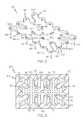
- FIG. 5depicts a perspective view of a heat exchanger fluid distribution manifold according to one or more embodiments shown and described herein;
- FIG. 6depicts a perspective view of a coolant fluid chamber of the heat exchanger fluid distribution manifold illustrated in FIG. 5 ;
- FIG. 7depicts a cross section view of the heat exchanger fluid distribution manifold illustrated in FIG. 5 ;
- FIG. 8depicts a side view of a power electronics module according to one or more embodiments shown and described herein.
- FIG. 1generally depicts one embodiment of a heat exchanger fluid distribution manifold.
- the heat exchanger fluid distribution manifoldgenerally comprises a manifold body that defines a coolant fluid chamber, a single fluid inlet and a plurality of fluid outlets.
- Coolant fluidsuch as water, ethylene glycol, refrigerants, etc.
- the coolantmay exit the heat exchanger fluid distribution manifold through the fluid outlets and be routed to a heat exchanger module that is thermally coupled to a heat generating device, such as a power electronics device.
- the coolant fluid chamberis configured such that the coolant fluid flow rate at each fluid outlet is substantially uniform and a total pressure drop within the coolant fluid chamber is minimized.
- the manifold bodyhas serpentine walls comprising spline features that are in close proximity to each fluid outlet. The shape of the serpentine walls and spline features are optimized such that velocity of direction of the cooling fluid flow is controlled to ensure that the coolant fluid flow rate at the fluid outlets is substantially uniform.
- the heat exchanger fluid distribution manifold 100generally comprises a manifold body 102 having a coolant fluid chamber 105 , a single fluid inlet channel 111 and a plurality of fluid outlet channels 122 disposed therein.
- the fluid inlet channelmay be fluidly coupled to a fluid line 152 (see FIG. 4 ) that is connected to a coolant fluid source (not shown).
- the coolant fluid sourcemay be a radiator of a vehicle.
- coolant fluidmay enter the heat exchanger fluid distribution manifold 100 via a fluid line and fluid inlet channel 111 /fluid inlet 110 and exit the heat exchanger fluid distribution manifold 100 via the plurality of fluid outlets 120 /fluid outlet channels 122 .
- a fluid inlet 110 at the coolant fluid chamber 105is connected or otherwise associated with the fluid inlet channel 111 .
- each fluid outlet 120is connected or otherwise associated with an individual fluid outlet channel 122 .
- the manifold body 102may be made of a metal material, such as aluminum, for example.
- the manifold body 102may also be made of a thermally insulating material, such as rigid plastic.
- the manifold body 102comprises a first half and a second half.
- the first and second halvesmay be machined or molded. When coupled together, the first and second halves define the internal features of the heat exchanger fluid distribution manifold 100 , such as the coolant fluid chamber 105 , the single fluid inlet channel 111 , and the plurality of fluid outlet channels 122 .
- the first and second halvesmay be coupled together by welding, adhesive or any other coupling methods.
- the manifold body 102is a single component that is molded to include the internal features and components described herein.
- FIG. 2illustrates the coolant fluid chamber 105 that is disposed in the heat exchanger fluid distribution manifold 100 that is illustrated in FIG. 1 .
- the coolant fluid chamber 105has a centrally-located, single fluid inlet 110 located on a first side 106 of the coolant fluid chamber 105 .
- coolant fluidmay enter the coolant fluid chamber 105 as depicted by arrow 150 .
- the plurality of fluid outlets 120are located about the single fluid inlet 110 in a grid pattern, with the single fluid inlet 110 located in the center of the grid pattern. Coolant fluid may flow out of the coolant fluid chamber through the fluid outlets as depicted by arrows 160 .
- the fluid outlets 120are located on a second side 107 of the coolant fluid chamber 105 that is opposite from the first side 106 .
- FIGS. 1-3have twenty-four fluid outlets 120 , more or fewer fluid outlets may be utilized.
- the distance between the fluid inlet and the fluid outletsvaries from fluid outlet to fluid outlet. For example, the distance between an inner fluid outlet 120 a and the fluid inlet 110 is greater than the distance between an outermost fluid outlet 120 e and the fluid inlet 110 . Because the distances between the fluid inlet and the various fluid outlets are not equal, a coolant fluid chamber having straight walls would cause uneven coolant flow rates at each fluid outlet 120 , as well as a relatively larger total pressure drop. As used herein, the total pressure drop is the pressure drop within the coolant fluid chamber from the fluid inlet to the farthest fluid outlet. To minimize pumping requirements to circulate coolant fluid through the heat exchanger fluid distribution manifold, the total pressure drop should be as low as possible.
- the coolant fluid flow rate for each fluid outletshould be substantially equal.
- a maximum difference in coolant fluid flow rate between respective fluid outletsis less than 1.000 ⁇ 10 ⁇ 3 kg/s.
- the coolant fluid chamber 105comprises a plurality of serpentine walls 130 .
- the serpentine walls 130are made up of a plurality of individual spline features 133 that are located close to the fluid outlets.
- a spline featureis defined by a curved wall portion that extends from one sharp angle or transition point to another sharp angle or transition point.
- spline feature 133 a illustrated in FIG. 2is located between transition point 134 and transition point 135 .
- the shape and size of the serpentine walls 130 and corresponding spline features 133are optimized to reduce the total pressure drop within the coolant fluid chamber 105 , as well as provide for a uniform coolant fluid flow rate at each fluid outlet 120 .
- the term optimized, as used herein,means that the serpentine walls are geometrically designed to provide substantially uniform coolant fluid flow rate at each fluid outlet.
- the serpentine walls 130are configured to guide the coolant fluid uniformly throughout the heat exchanger fluid distribution manifold 100 .
- FIG. 3illustrates coolant fluid flow within the heat exchanger fluid distribution manifold 100 .
- the arrows 140indicate flow direction of the coolant fluid.
- the velocity of the coolant fluiddecreases with a rise in static pressure as the remaining fluid travels away from the fluid inlet. Therefore, the fluid flow rate increases moving linearly from a first outlet toward the last outlet furthest from fluid inlet.
- embodiments described hereinutilize the serpentine walls 130 to optimize the area as well as the walls of the coolant fluid chamber 105 to obtain even coolant fluid flow distribution and minimize pressure loss.
- the serpentine walls 130alter the velocity field of the coolant fluid flow.
- interior routing features 170may also be located within the coolant fluid chamber 105 to provide optimal routing of coolant fluid.
- the interior routing features 170provide the same effect as the spline features 133 of the serpentine walls 130 for interior fluid outlets 120 a - d that are not located near a serpentine wall.
- the interior routing features 170are symmetrically located just past interior fluid outlets 120 a - d along a radial direction as indicated by the coolant fluid flow arrows 140 .
- the interior routing features 170have a curved wall that faces the fluid outlet.
- the serpentine walls 130 and interior routing features 170are configured to maintain substantially equal coolant fluid velocity and pressure at fluid outlet despite the unequal distances between each fluid outlet and the fluid inlet. In such a manner, coolant fluid is evenly and efficiently distributed throughout the heat exchanger fluid distribution manifold 100 .
- the total pressure drop within the heat exchanger fluid distribution manifold 100is less than 2 kPa. However, much lower total pressure drops may be achievable.
- the geometric shape of the serpentine walls 130 , spline features 133 and interior routing features 170 of the coolant fluid chambermay be determined by the use of an optimization procedure.
- the optimization procedurebegins with an optimized channel topology determined using a gradient-based optimizer coupled with a finite element analysis package.
- the term topologyrefers to the configuration of the serpentine walls, spline features and interior routing features.
- a generic design domainis optimized to minimize the fluid flow resistance given equivalent fluid outlet velocity boundary conditions.
- the resultant optimized topologyis then utilized as an initial condition or suggestion for further fluid flow analysis. More specifically, the resultant topology is synthesized into a full distribution manifold structure model (e.g., a computer aided design module) that is used in subsequent fluid flow numerical simulations.
- manual adjustment of the final shape of the features of the coolant fluid chambermay be performed to further interpret the topology optimization result and properly balance the overall flow rate distribution.
- a computer simulationwas performed on the geometry of the heat exchanger fluid distribution manifold illustrated in FIGS. 1-3 .
- Total pressure drop and fluid flow velocity at each fluid outletwere determined.
- the simulated heat exchanger fluid distribution manifoldhad a coolant fluid chamber that was 120 mm in length, 80 mm in width, and 3 mm in depth.
- the single fluid inlethad a diameter of 6 mm and the fluid outlets had a diameter of 3 mm.
- the velocity of the coolant fluid introduced into the heat exchanger fluid distribution manifold at the fluid inletwas approximately 2.0 m/s.
- the velocity of the coolant fluid at each of the fluid outletsaveraged 0.5 m/s with a maximum differential between fluid outlets of 0.05 m/s.
- the average mass flow rate at the fluid outletswas 2.6 ⁇ 10 ⁇ 3 kg/s, with a maximum mass flow rate differential between fluid outlets of 0.5 ⁇ 10 ⁇ 3 kg/s.
- the total pressure drop within the simulated heat exchanger fluid distribution manifoldwas about 2 kPa.
- the power electronics module 180comprises the heat exchanger fluid distribution manifold 100 , a plurality of heat exchanger modules 190 , a substrate layer 192 and a plurality of power electronic devices 184 .
- an individual heat exchanger module 190is coupled to a single fluid outlet channel 122 of the heat exchanger fluid distribution manifold 100 . Therefore, there are twenty-four heat exchanger modules 190 fluidly coupled to the heat exchanger fluid distribution manifold 100 .
- a single heat exchanger modulemay be fluidly coupled to two or more fluid outlet channels.
- a single heat exchanger device or modulemay be coupled to all of the fluid outlets of the manifold.
- a power electronics device 184such as an IGBT, RC-IGBT, diode, MOSFET, etc., is thermally coupled to a heat exchanger module 190 at a heat exchanging surface 191 .
- more than one power electronics devicemay be thermally coupled to a heat exchanging module. Heat generated by the power electronics device 184 is transferred to the coolant fluid circulating within the heat exchanger module 190 , thereby cooling the power electronics device 184 .
- the heat exchanger modules 190may be any type of heat exchanger that utilizes a coolant fluid to remove heat from a heat source.
- an optional thermally conductive substrate layer 192is located between the heat exchanger modules and the power electronics devices.
- the power electronics devices 184 , heat exchanger modules 190 , and the thermally conductive substrate layer 192may be coupled together by solder, brazing or other thermal coupling methods.
- the heat exchanger fluid distribution manifold 100may be fluidly coupled to a coolant fluid source (not shown) via a fluid line 152 that is coupled to the fluid inlet channel 111 .
- Coolant fluidenters the heat exchanger fluid distribution manifold 100 through the fluid line 152 and the fluid inlet channel 111 and exits the heat exchanger fluid distribution manifold 100 through the plurality of fluid outlets 120 and fluid outlet channels 122 as described above.
- the coolant fluidpasses through the fluid outlet channels 122 and into the heat exchanger modules 190 . Heat generated by the power electronics devices 184 is transferred to the coolant fluid circulating within the heat exchanger modules 190 .
- the warmed coolant fluid within the heat exchanger modules 190may exit through an outlet port (not shown) and returned to the coolant fluid source.
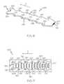
- the embodimentcomprises a single fluid inlet 210 at an edge of the heat exchanger fluid distribution manifold 200 and a plurality of fluid outlets 220 that are located along direction X with respect to the fluid inlet.
- the heat exchanger fluid distribution manifold 200generally comprises a manifold body 202 having a coolant fluid chamber 205 , and a plurality of fluid outlet channels 222 disposed therein. Each fluid outlet 220 is connected or otherwise associated with an individual fluid outlet channel 222 .
- the fluid inlet 210may be fluidly coupled to a fluid line 252 (see FIG. 8 ) that is connected to a coolant fluid source (not shown). Coolant fluid may enter the heat exchanger fluid distribution manifold 200 via a fluid line and fluid inlet 210 and exit the heat exchanger fluid distribution manifold 200 via the plurality of fluid outlets 220 /fluid outlet channels 222 .
- the manifold body 202may be made of a metal material, such as aluminum, for example.
- the manifold body 202may also be made of a thermally insulating material, such as rigid plastic.
- the manifold bodycomprises a first half and a second half.
- the manifold body 202is a single component that is molded to include the internal features and components described herein.
- FIG. 6illustrates the coolant fluid chamber 205 that is disposed in the heat exchanger fluid distribution manifold 200 that is illustrated in FIG. 5 .
- the coolant fluid chamber 205has a single fluid inlet 210 located on a first end 207 . Coolant fluid may enter the coolant fluid chamber 205 as depicted by arrow 250 .
- the plurality of fluid outlets 220are located in two rows that extend from the first end 207 toward a second end that is opposite from the first end 207 . In another embodiment, the plurality of fluid outlets may be arranged in a single row, or in more than two rows. Further, although the embodiment illustrated in FIGS. 5-7 have twelve fluid outlets 220 , more or fewer fluid outlets 220 may be utilized.
- the distance between the fluid inlet and the fluid outletsvaries from fluid outlet to fluid outlet. For example, the distance between the fluid inlet 210 increases along the rows of plurality of fluid outlets 220 in direction X. Because the distances between the fluid inlet and the various fluid outlets are not equal, a coolant fluid chamber having straight walls would cause uneven coolant flow rates at each fluid outlet 220 , as well as a relatively larger total pressure drop.
- the coolant fluid chamber 205comprises a plurality of serpentine walls 230 that are similar in shape as the serpentine walls 130 described above.
- the geometric shape of the serpentine walls 230 and spline features 233may be determined by the use of the optimization procedure described above.
- the serpentine walls 230 illustrated in FIGS. 5-7are made up of a plurality of individual spline features 233 that are located proximate to the fluid outlets.
- the serpentine walls 230 and corresponding spline features 233are optimized to reduce the total pressure drop within the coolant fluid chamber 205 as well as provide for a uniform coolant fluid flow rate at each fluid outlet 220 .
- the serpentine walls 230are configured to guide the coolant fluid uniformly throughout the heat exchanger fluid distribution manifold 200 .
- FIG. 7illustrates coolant fluid flow within the heat exchanger fluid distribution manifold 200 .
- the arrows 240indicate flow direction of the coolant fluid.
- the embodiment illustrated in FIGS. 5-7utilizes the serpentine walls 230 to optimize the area as well as the walls of the coolant fluid chamber 205 of the heat exchanger fluid distribution manifold 200 to obtain even coolant fluid flow distribution and minimize pressure loss.
- the geometric shape of the serpentine walls 230are designed to maintain substantially equal coolant fluid velocity and pressure at the fluid outlets despite the unequal distances between each fluid outlet and the fluid inlet. In such a manner, coolant fluid may be evenly and efficiently distributed throughout the heat exchanger fluid distribution manifold 200 .
- a computer simulationwas performed on the geometry of the heat exchanger fluid distribution manifold illustrated in FIGS. 5-7 to determine total pressure drop and fluid flow velocity at each fluid outlet.
- the simulated heat exchanger fluid distribution manifoldhad a coolant fluid chamber that was 130 mm in length, 40 mm in width, and 3 mm in depth.
- the single fluid inlethad a length of 20 mm and the fluid outlets had a diameter of 3 mm.
- the velocity of the coolant fluid introduced into the heat exchanger fluid distribution manifold at the fluid inletwas 0.8 m/s.
- the velocity of the coolant fluid at each of the fluid outletsaveraged about 0.79 m/s with a maximum differential between fluid outlets of about 0.05 m/s.
- the average mass flow rate at the fluid outletswas about 3.6 ⁇ 10 ⁇ 3 kg/s, with a maximum mass flow rate differential between the fluid outlets closest to the fluid inlet and the fluid outlets further from the fluid inlet of about 0.5 ⁇ 10 ⁇ 3 kg/s.
- the total pressure drop within the simulated heat exchanger fluid distribution manifoldwas 0.5 kPa.
- the power electronics module 280comprises the heat exchanger fluid distribution manifold 200 , a plurality of heat exchanger modules 290 , an optional substrate layer 292 , and a plurality of power electronic devices 284 .
- an individual heat exchanger module 290is coupled to a single fluid outlet channel 222 of the heat exchanger fluid distribution manifold 200 . Therefore, there are twelve heat exchanger modules 290 fluidly coupled to the heat exchanger fluid distribution manifold 200 .
- a single heat exchanger modulemay be fluidly coupled to two or more fluid outlet channels.
- a single heat exchanger device or modulemay be coupled to all of the fluid outlets of the manifold.
- a power electronics device 284(e.g., an IGBT, RC-IGBT, diode, MOSFET, etc.) is thermally coupled to a heat exchanger module 290 at a heat exchanging surface 291 .
- more than one power electronics devicemay be thermally coupled to a heat exchanger module.
- the heat exchanger modules 290may be any type of heat exchanger that utilizes a coolant fluid to remove heat from a heat source.
- an optional thermally conductive substrate layer 292is located between the heat exchanger modules and the power electronics devices.
- the power electronics devices 294 , heat exchanger modules 290 , and the thermally conductive substrate layer 292may be coupled together by solder, brazing or other thermal coupling methods.
- the heat exchanger fluid distribution manifold 200may be fluidly coupled to a coolant fluid source (not shown) via a fluid line 252 that is coupled to the fluid inlet channel 211 .
- Coolant fluidenters the heat exchanger fluid distribution manifold 200 through the fluid line 250 and the fluid inlet channel 211 and exits the heat exchanger fluid distribution manifold 200 through the plurality of fluid outlets 220 and fluid outlet channels 222 as described above.
- the coolant fluidpasses through the fluid outlet channels 222 and into the heat exchanger modules 290 . Heat generated by the power electronics devices 284 is transferred to the coolant fluid circulating within the heat exchanger modules 290 .
- the warmed coolant fluid within the heat exchanger modules 290may exit through an outlet port (not shown) and returned to the coolant fluid source.
- the heat exchanger fluid distribution manifolds described hereinhave coolant fluid chambers with serpentine walls that are designed to optimize coolant fluid flow such that the coolant fluid flow rate at each of the fluid outlets is substantially uniform.
- the serpentine wallsalso minimize a total pressure drop within the heat exchanger fluid distribution manifold. Reduced total pressure drop minimizes the pumping requirement needed to provide coolant fluid through the manifold, and a substantially uniform coolant rate ensures that each heat exchanger coupled to the manifold receives an equal amount of coolant fluid at an equal rate.
- the heat exchanger fluid distribution manifolds described hereinmay be incorporated into power electronics modules having one or more heat exchangers and one or more power electronics devices.
Landscapes
- Engineering & Computer Science (AREA)
- Physics & Mathematics (AREA)
- Thermal Sciences (AREA)
- Mechanical Engineering (AREA)
- General Engineering & Computer Science (AREA)
- Condensed Matter Physics & Semiconductors (AREA)
- General Physics & Mathematics (AREA)
- Computer Hardware Design (AREA)
- Microelectronics & Electronic Packaging (AREA)
- Power Engineering (AREA)
- Cooling Or The Like Of Semiconductors Or Solid State Devices (AREA)
- Cooling Or The Like Of Electrical Apparatus (AREA)
Abstract
Description
Claims (18)
Priority Applications (2)
| Application Number | Priority Date | Filing Date | Title |
|---|---|---|---|
| US12/839,039US8077460B1 (en) | 2010-07-19 | 2010-07-19 | Heat exchanger fluid distribution manifolds and power electronics modules incorporating the same |
| JP2011158004AJP5806023B2 (en) | 2010-07-19 | 2011-07-19 | Fluid distribution manifold for heat exchanger and power electronics module incorporating fluid distribution manifold for heat exchanger |
Applications Claiming Priority (1)
| Application Number | Priority Date | Filing Date | Title |
|---|---|---|---|
| US12/839,039US8077460B1 (en) | 2010-07-19 | 2010-07-19 | Heat exchanger fluid distribution manifolds and power electronics modules incorporating the same |
Publications (1)
| Publication Number | Publication Date |
|---|---|
| US8077460B1true US8077460B1 (en) | 2011-12-13 |
Family
ID=45092706
Family Applications (1)
| Application Number | Title | Priority Date | Filing Date |
|---|---|---|---|
| US12/839,039Expired - Fee RelatedUS8077460B1 (en) | 2010-07-19 | 2010-07-19 | Heat exchanger fluid distribution manifolds and power electronics modules incorporating the same |
Country Status (2)
| Country | Link |
|---|---|
| US (1) | US8077460B1 (en) |
| JP (1) | JP5806023B2 (en) |
Cited By (23)
| Publication number | Priority date | Publication date | Assignee | Title |
|---|---|---|---|---|
| US20110299244A1 (en)* | 2010-06-08 | 2011-12-08 | Toyota Motor Engineering & Manufacturing | Cooling member for heat containing device |
| US20120063085A1 (en)* | 2010-09-13 | 2012-03-15 | Toyota Motor Engineering & Manufacturing North America, Inc. | Jet Impingement Heat Exchanger Apparatuses and Power Electronics Modules |
| US20120145355A1 (en)* | 2010-12-09 | 2012-06-14 | Perkinelmer Elcos Gmbh | Homogeneous liquid cooling of led array |
| US20120170222A1 (en)* | 2011-01-05 | 2012-07-05 | Toyota Motor Engineering & Manufacturing North America, Inc. | Cold plate assemblies and power electronics modules |
| US20120212907A1 (en)* | 2011-02-17 | 2012-08-23 | Toyota Motor Engineering & Manufacturing North America, Inc. | Power electronics modules and power electronics module assemblies |
| WO2012166574A3 (en)* | 2011-05-27 | 2013-01-24 | Corning Incorporated | Glass molding system and related apparatus and method |
| US8643173B1 (en) | 2013-01-04 | 2014-02-04 | Toyota Motor Engineering & Manufacturing North America, Inc. | Cooling apparatuses and power electronics modules with single-phase and two-phase surface enhancement features |
| US20140190665A1 (en)* | 2013-01-04 | 2014-07-10 | Purdue University | Modular Jet Impingement Cooling Apparatuses With Exchangeable Jet Plates |
| US8981556B2 (en) | 2013-03-19 | 2015-03-17 | Toyota Motor Engineering & Manufacturing North America, Inc. | Jet impingement cooling apparatuses having non-uniform jet orifice sizes |
| US9131631B2 (en) | 2013-08-08 | 2015-09-08 | Toyota Motor Engineering & Manufacturing North America, Inc. | Jet impingement cooling apparatuses having enhanced heat transfer assemblies |
| US9247679B2 (en) | 2013-05-24 | 2016-01-26 | Toyota Motor Engineering & Manufacturing North America, Inc. | Jet impingement coolers and power electronics modules comprising the same |
| US9257365B2 (en) | 2013-07-05 | 2016-02-09 | Toyota Motor Engineering & Manufacturing North America, Inc. | Cooling assemblies and power electronics modules having multiple-porosity structures |
| US9353999B2 (en) | 2012-07-30 | 2016-05-31 | Toyota Motor Engineering & Manufacturing North America, Inc. | Cooling apparatuses and electronics modules having branching microchannels |
| US9460985B2 (en) | 2013-01-04 | 2016-10-04 | Toyota Motor Engineering & Manufacturing North America, Inc. | Cooling apparatuses having a jet orifice surface with alternating vapor guide channels |
| US9803938B2 (en) | 2013-07-05 | 2017-10-31 | Toyota Motor Engineering & Manufacturing North America, Inc. | Cooling assemblies having porous three dimensional surfaces |
| US10306801B2 (en)* | 2016-09-30 | 2019-05-28 | International Business Machines Corporation | Cold plate device for a two-phase cooling system |
| CN110164835A (en)* | 2019-06-14 | 2019-08-23 | 北京工业大学 | A kind of manifold-type labyrinth microchannel minitype radiator |
| CN110731000A (en)* | 2017-06-09 | 2020-01-24 | 马特森技术有限公司 | Plasma stripping tool with uniformity control |
| US20210378139A1 (en)* | 2020-05-29 | 2021-12-02 | Google Llc | Impinging Jet Manifold For Chip Cooling Near Edge Jets |
| US20220051967A1 (en)* | 2018-09-17 | 2022-02-17 | Agency For Science, Technology And Research | Liquid cooling module and method of forming the same |
| US11270925B2 (en) | 2020-05-28 | 2022-03-08 | Google Llc | Heat distribution device with flow channels |
| EP4171185A1 (en)* | 2021-10-22 | 2023-04-26 | Carrier Corporation | Seal for thermal interface material of power electronics modules |
| CN119864329A (en)* | 2025-03-25 | 2025-04-22 | 浙江大学 | Radial micro-channel radiator with manifold structure and radiating system |
Citations (93)
| Publication number | Priority date | Publication date | Assignee | Title |
|---|---|---|---|---|
| US4322737A (en) | 1979-11-20 | 1982-03-30 | Intel Corporation | Integrated circuit micropackaging |
| US4392153A (en) | 1978-05-01 | 1983-07-05 | General Electric Company | Cooled semiconductor power module including structured strain buffers without dry interfaces |
| US4494171A (en) | 1982-08-24 | 1985-01-15 | Sundstrand Corporation | Impingement cooling apparatus for heat liberating device |
| US4733293A (en) | 1987-02-13 | 1988-03-22 | Unisys Corporation | Heat sink device assembly for encumbered IC package |
| US4748495A (en) | 1985-08-08 | 1988-05-31 | Dypax Systems Corporation | High density multi-chip interconnection and cooling package |
| US4783721A (en) | 1985-10-04 | 1988-11-08 | Fujitsu Limited | Cooling system for an electronic circuit device |
| US4868712A (en) | 1987-02-04 | 1989-09-19 | Woodman John K | Three dimensional integrated circuit package |
| US4920574A (en) | 1985-10-04 | 1990-04-24 | Fujitsu Limited | Cooling system for an electronic circuit device |
| US5016138A (en) | 1987-10-27 | 1991-05-14 | Woodman John K | Three dimensional integrated circuit package |
| US5023695A (en) | 1988-05-09 | 1991-06-11 | Nec Corporation | Flat cooling structure of integrated circuit |
| US5079619A (en) | 1990-07-13 | 1992-01-07 | Sun Microsystems, Inc. | Apparatus for cooling compact arrays of electronic circuitry |
| US5088005A (en) | 1990-05-08 | 1992-02-11 | Sundstrand Corporation | Cold plate for cooling electronics |
| US5119175A (en) | 1990-08-17 | 1992-06-02 | Westinghouse Electric Corp. | High power density solid-state, insulating coolant module |
| US5145001A (en) | 1989-07-24 | 1992-09-08 | Creare Inc. | High heat flux compact heat exchanger having a permeable heat transfer element |
| US5210440A (en) | 1991-06-03 | 1993-05-11 | Vlsi Technology, Inc. | Semiconductor chip cooling apparatus |
| US5228502A (en) | 1991-09-04 | 1993-07-20 | International Business Machines Corporation | Cooling by use of multiple parallel convective surfaces |
| US5260850A (en) | 1991-03-08 | 1993-11-09 | Cray Computer Corporation | Logic module assembly for confining and directing the flow of cooling fluid |
| US5270572A (en) | 1991-06-26 | 1993-12-14 | Hitachi, Ltd. | Liquid impingement cooling module for semiconductor devices |
| US5269372A (en) | 1992-12-21 | 1993-12-14 | International Business Machines Corporation | Intersecting flow network for a cold plate cooling system |
| US5394299A (en) | 1992-12-21 | 1995-02-28 | International Business Machines Corporation | Topology matched conduction cooling module |
| US5546274A (en) | 1995-03-10 | 1996-08-13 | Sun Microsystems, Inc. | Three-dimensional compact array of electronic circuitry |
| US5912800A (en) | 1997-09-03 | 1999-06-15 | International Business Machines Corporation | Electronic packages and method to enhance the passive thermal management of electronic packages |
| US5983997A (en) | 1996-10-17 | 1999-11-16 | Brazonics, Inc. | Cold plate having uniform pressure drop and uniform flow rate |
| US6058010A (en) | 1998-11-06 | 2000-05-02 | International Business Machines Corporation | Enhanced test head liquid cooled cold plate |
| US6167948B1 (en) | 1996-11-18 | 2001-01-02 | Novel Concepts, Inc. | Thin, planar heat spreader |
| US6242075B1 (en) | 1998-11-20 | 2001-06-05 | Hewlett-Packard Company | Planar multilayer ceramic structures with near surface channels |
| US6305463B1 (en) | 1996-02-22 | 2001-10-23 | Silicon Graphics, Inc. | Air or liquid cooled computer module cold plate |
| US6333853B2 (en) | 1998-12-22 | 2001-12-25 | S&C Electric Company | Configuration of power electronic device modules |
| US20020053726A1 (en) | 2000-11-09 | 2002-05-09 | Kazuyuki Mikubo | Semiconductor device attaining both high speed processing and sufficient cooling capacity |
| US6431260B1 (en) | 2000-12-21 | 2002-08-13 | International Business Machines Corporation | Cavity plate and jet nozzle assemblies for use in cooling an electronic module, and methods of fabrication thereof |
| US6501654B2 (en) | 2000-09-29 | 2002-12-31 | Nanostream, Inc. | Microfluidic devices for heat transfer |
| US6580609B2 (en) | 2001-05-16 | 2003-06-17 | Cray Inc. | Method and apparatus for cooling electronic components |
| US20030196451A1 (en) | 2002-04-11 | 2003-10-23 | Lytron, Inc. | Contact cooling device |
| US6665185B1 (en) | 2002-10-09 | 2003-12-16 | Ltx Corporation | Apparatus and method for embedded fluid cooling in printed circuit boards |
| US6828675B2 (en) | 2001-09-26 | 2004-12-07 | Modine Manufacturing Company | Modular cooling system and thermal bus for high power electronics cabinets |
| US6903931B2 (en) | 2002-06-13 | 2005-06-07 | Raytheon Company | Cold plate assembly |
| US20050121180A1 (en) | 2003-09-26 | 2005-06-09 | Thermal Form & Function Llc | Use of graphite foam materials in pumped liquid, two phase cooling, cold plates |
| US6942018B2 (en) | 2001-09-28 | 2005-09-13 | The Board Of Trustees Of The Leland Stanford Junior University | Electroosmotic microchannel cooling system |
| US20050199372A1 (en) | 2004-03-08 | 2005-09-15 | Frazer James T. | Cold plate and method of making the same |
| US6952346B2 (en) | 2004-02-24 | 2005-10-04 | Isothermal Systems Research, Inc | Etched open microchannel spray cooling |
| US20050225938A1 (en) | 2004-04-08 | 2005-10-13 | Richard Montgomery | Cold plate |
| US6972365B2 (en) | 2001-06-27 | 2005-12-06 | Thermal Corp. | Thermal management system and method for electronics system |
| US20060002086A1 (en) | 2004-06-30 | 2006-01-05 | Teneketges Nicholas J | Heat exchange apparatus with parallel flow |
| US6986382B2 (en) | 2002-11-01 | 2006-01-17 | Cooligy Inc. | Interwoven manifolds for pressure drop reduction in microchannel heat exchangers |
| US6988535B2 (en) | 2002-11-01 | 2006-01-24 | Cooligy, Inc. | Channeled flat plate fin heat exchange system, device and method |
| US6992382B2 (en) | 2003-12-29 | 2006-01-31 | Intel Corporation | Integrated micro channels and manifold/plenum using separate silicon or low-cost polycrystalline silicon |
| US6994151B2 (en) | 2002-10-22 | 2006-02-07 | Cooligy, Inc. | Vapor escape microchannel heat exchanger |
| US7017654B2 (en) | 2003-03-17 | 2006-03-28 | Cooligy, Inc. | Apparatus and method of forming channels in a heat-exchanging device |
| US7058101B2 (en) | 2003-09-20 | 2006-06-06 | Spectra Physics, Inc. | Stepped manifold array of microchannel heat sinks |
| US7104312B2 (en) | 2002-11-01 | 2006-09-12 | Cooligy, Inc. | Method and apparatus for achieving temperature uniformity and hot spot cooling in a heat producing device |
| US7119284B2 (en) | 2001-06-28 | 2006-10-10 | Lear Corporation | Printed circuit board with isolated metallic substrate comprising an integrated cooling system |
| US20060291164A1 (en) | 2005-06-28 | 2006-12-28 | Myers Bruce A | Fluid-cooled electronic system |
| US20070034360A1 (en) | 2005-06-08 | 2007-02-15 | Hall Jack P | High performance cooling assembly for electronics |
| US20070041160A1 (en) | 2005-08-19 | 2007-02-22 | Kehret William E | Thermal management for a ruggedized electronics enclosure |
| US7184269B2 (en) | 2004-12-09 | 2007-02-27 | International Business Machines Company | Cooling apparatus and method for an electronics module employing an integrated heat exchange assembly |
| US7188662B2 (en) | 2004-06-04 | 2007-03-13 | Cooligy, Inc. | Apparatus and method of efficient fluid delivery for cooling a heat producing device |
| US20070074856A1 (en) | 2005-10-04 | 2007-04-05 | Bhatti Mohinder S | Multi-layered micro-channel heat sink |
| US7205653B2 (en) | 2004-08-17 | 2007-04-17 | Delphi Technologies, Inc. | Fluid cooled encapsulated microelectronic package |
| US7204303B2 (en) | 2003-12-17 | 2007-04-17 | Lytron, Inc. | Flat tube cold plate assembly |
| US7212409B1 (en) | 2005-12-05 | 2007-05-01 | Hewlett-Packard Development Company, L.P. | Cam actuated cold plate |
| US20070119565A1 (en) | 2005-11-14 | 2007-05-31 | International Business Machines Corporation | Cooling device |
| US7250674B2 (en) | 2000-04-19 | 2007-07-31 | Denso Corporation | Coolant cooled type semiconductor device |
| US20070177352A1 (en) | 2006-02-02 | 2007-08-02 | Monfarad Ali H | Direct contact cooling liquid embedded package for a central processor unit |
| US20070188991A1 (en) | 2004-09-08 | 2007-08-16 | Thermal Corp. | Liquid cooled heat sink with cold plate retention mechanism |
| US20070230127A1 (en) | 2006-03-28 | 2007-10-04 | Delphi Technologies, Inc. | Fluid cooled electronic assembly |
| US20070236883A1 (en) | 2006-04-05 | 2007-10-11 | Javier Ruiz | Electronics assembly having heat sink substrate disposed in cooling vessel |
| US7295440B2 (en) | 2006-03-07 | 2007-11-13 | Honeywell International, Inc. | Integral cold plate/chasses housing applicable to force-cooled power electronics |
| US7298618B2 (en) | 2005-10-25 | 2007-11-20 | International Business Machines Corporation | Cooling apparatuses and methods employing discrete cold plates compliantly coupled between a common manifold and electronics components of an assembly to be cooled |
| US7298617B2 (en) | 2005-10-25 | 2007-11-20 | International Business Machines Corporation | Cooling apparatus and method employing discrete cold plates disposed between a module enclosure and electronics components to be cooled |
| US7302998B2 (en) | 2000-06-08 | 2007-12-04 | Mikros Manufacturing, Inc. | Normal-flow heat exchanger |
| US7327570B2 (en) | 2004-12-22 | 2008-02-05 | Hewlett-Packard Development Company, L.P. | Fluid cooled integrated circuit module |
| US7336493B2 (en) | 2005-07-19 | 2008-02-26 | Bae Systems Information And Electronic Systems Integration Inc. | Cold plate cooling apparatus for a rack mounted electronic module |
| US7355277B2 (en) | 2003-12-31 | 2008-04-08 | Intel Corporation | Apparatus and method integrating an electro-osmotic pump and microchannel assembly into a die package |
| US20080093053A1 (en) | 2006-10-24 | 2008-04-24 | Seaho Song | Systems and methods for providing two phase cooling |
| US7393226B2 (en) | 2006-03-08 | 2008-07-01 | Microelectronics Assembly Technologies, Inc. | Thin multichip flex-module |
| US7397662B2 (en) | 2003-12-05 | 2008-07-08 | Nec Corporation | Electronic card unit and method for removing heat from a heat-generating component on a printed circuit board |
| US7429792B2 (en) | 2006-06-29 | 2008-09-30 | Hynix Semiconductor Inc. | Stack package with vertically formed heat sink |
| US7450378B2 (en) | 2006-10-25 | 2008-11-11 | Gm Global Technology Operations, Inc. | Power module having self-contained cooling system |
| US20090032937A1 (en) | 2007-07-30 | 2009-02-05 | Gm Global Technology Operations, Inc. | Cooling systems for power semiconductor devices |
| US7495916B2 (en) | 2007-06-19 | 2009-02-24 | Honeywell International Inc. | Low cost cold plate with film adhesive |
| US20090090490A1 (en) | 2006-04-06 | 2009-04-09 | Toyota Jidosha Kabushiki Kaisha | Cooler |
| US7599184B2 (en) | 2006-02-16 | 2009-10-06 | Cooligy Inc. | Liquid cooling loops for server applications |
| US7608924B2 (en) | 2007-05-03 | 2009-10-27 | Delphi Technologies, Inc. | Liquid cooled power electronic circuit comprising stacked direct die cooled packages |
| US20090294106A1 (en) | 2008-05-28 | 2009-12-03 | Matteo Flotta | Method and apparatus for chip cooling |
| US20100000766A1 (en) | 2008-07-02 | 2010-01-07 | Thales Holdings Uk Plc | Printed circuit board assembly |
| US20100038774A1 (en) | 2008-08-18 | 2010-02-18 | General Electric Company | Advanced and integrated cooling for press-packages |
| US7679911B2 (en) | 2005-06-01 | 2010-03-16 | Robert J Rapp | Electronic package whereby an electronic assembly is packaged within an enclosure that is designed to act as a heat pipe |
| US20100142150A1 (en) | 2008-06-20 | 2010-06-10 | International Business Machines Corporation | Cooling apparatus with cold plate formed in situ on a surface to be cooled |
| US7738249B2 (en) | 2007-10-25 | 2010-06-15 | Endicott Interconnect Technologies, Inc. | Circuitized substrate with internal cooling structure and electrical assembly utilizing same |
| US7795726B2 (en) | 2007-05-03 | 2010-09-14 | Delphi Technologies, Inc. | Liquid cooled power electronic circuit comprising a stacked array of directly cooled semiconductor chips |
| US20100242178A1 (en) | 2009-03-30 | 2010-09-30 | Goetting Andrew T | Inflatable cushion for turning a bed into a sofa |
| US20100246117A1 (en) | 2008-02-28 | 2010-09-30 | International Business Machines Coporation | Variable flow computer cooling system for a data center and method of operation |
| US7839642B2 (en) | 2008-04-04 | 2010-11-23 | Liebert Corporation | Heat-sink brace for fault-force support |
Family Cites Families (6)
| Publication number | Priority date | Publication date | Assignee | Title |
|---|---|---|---|---|
| JPS62257796A (en)* | 1986-05-02 | 1987-11-10 | 株式会社日立製作所 | Cooling device for electronic parts |
| JPH0595064A (en)* | 1991-10-01 | 1993-04-16 | Hitachi Ltd | Semiconductor cooling device |
| JP3857060B2 (en)* | 2001-02-09 | 2006-12-13 | 株式会社東芝 | Heating element cooling device |
| JP4005878B2 (en)* | 2002-08-30 | 2007-11-14 | 株式会社東芝 | Jet-type heating element cooling device having multiple headers and power electronics device |
| US7536870B2 (en)* | 2006-03-30 | 2009-05-26 | International Business Machines Corporation | High power microjet cooler |
| EP2291859B1 (en)* | 2008-06-18 | 2016-03-30 | Brusa Elektronik AG | Cooling system, in particular for electronic structural units |
- 2010
- 2010-07-19USUS12/839,039patent/US8077460B1/ennot_activeExpired - Fee Related
- 2011
- 2011-07-19JPJP2011158004Apatent/JP5806023B2/ennot_activeExpired - Fee Related
Patent Citations (106)
| Publication number | Priority date | Publication date | Assignee | Title |
|---|---|---|---|---|
| US4392153A (en) | 1978-05-01 | 1983-07-05 | General Electric Company | Cooled semiconductor power module including structured strain buffers without dry interfaces |
| US4322737A (en) | 1979-11-20 | 1982-03-30 | Intel Corporation | Integrated circuit micropackaging |
| US4494171A (en) | 1982-08-24 | 1985-01-15 | Sundstrand Corporation | Impingement cooling apparatus for heat liberating device |
| US4748495A (en) | 1985-08-08 | 1988-05-31 | Dypax Systems Corporation | High density multi-chip interconnection and cooling package |
| US4783721A (en) | 1985-10-04 | 1988-11-08 | Fujitsu Limited | Cooling system for an electronic circuit device |
| US4920574A (en) | 1985-10-04 | 1990-04-24 | Fujitsu Limited | Cooling system for an electronic circuit device |
| US4868712A (en) | 1987-02-04 | 1989-09-19 | Woodman John K | Three dimensional integrated circuit package |
| US4733293A (en) | 1987-02-13 | 1988-03-22 | Unisys Corporation | Heat sink device assembly for encumbered IC package |
| US5016138A (en) | 1987-10-27 | 1991-05-14 | Woodman John K | Three dimensional integrated circuit package |
| US5023695A (en) | 1988-05-09 | 1991-06-11 | Nec Corporation | Flat cooling structure of integrated circuit |
| US5145001A (en) | 1989-07-24 | 1992-09-08 | Creare Inc. | High heat flux compact heat exchanger having a permeable heat transfer element |
| US5088005A (en) | 1990-05-08 | 1992-02-11 | Sundstrand Corporation | Cold plate for cooling electronics |
| US5079619A (en) | 1990-07-13 | 1992-01-07 | Sun Microsystems, Inc. | Apparatus for cooling compact arrays of electronic circuitry |
| US5119175A (en) | 1990-08-17 | 1992-06-02 | Westinghouse Electric Corp. | High power density solid-state, insulating coolant module |
| US5260850A (en) | 1991-03-08 | 1993-11-09 | Cray Computer Corporation | Logic module assembly for confining and directing the flow of cooling fluid |
| US5210440A (en) | 1991-06-03 | 1993-05-11 | Vlsi Technology, Inc. | Semiconductor chip cooling apparatus |
| US5270572A (en) | 1991-06-26 | 1993-12-14 | Hitachi, Ltd. | Liquid impingement cooling module for semiconductor devices |
| US5228502A (en) | 1991-09-04 | 1993-07-20 | International Business Machines Corporation | Cooling by use of multiple parallel convective surfaces |
| US5269372A (en) | 1992-12-21 | 1993-12-14 | International Business Machines Corporation | Intersecting flow network for a cold plate cooling system |
| US5394299A (en) | 1992-12-21 | 1995-02-28 | International Business Machines Corporation | Topology matched conduction cooling module |
| US5546274A (en) | 1995-03-10 | 1996-08-13 | Sun Microsystems, Inc. | Three-dimensional compact array of electronic circuitry |
| US6305463B1 (en) | 1996-02-22 | 2001-10-23 | Silicon Graphics, Inc. | Air or liquid cooled computer module cold plate |
| US5983997A (en) | 1996-10-17 | 1999-11-16 | Brazonics, Inc. | Cold plate having uniform pressure drop and uniform flow rate |
| US6167948B1 (en) | 1996-11-18 | 2001-01-02 | Novel Concepts, Inc. | Thin, planar heat spreader |
| US5912800A (en) | 1997-09-03 | 1999-06-15 | International Business Machines Corporation | Electronic packages and method to enhance the passive thermal management of electronic packages |
| US6058010A (en) | 1998-11-06 | 2000-05-02 | International Business Machines Corporation | Enhanced test head liquid cooled cold plate |
| US6242075B1 (en) | 1998-11-20 | 2001-06-05 | Hewlett-Packard Company | Planar multilayer ceramic structures with near surface channels |
| US6333853B2 (en) | 1998-12-22 | 2001-12-25 | S&C Electric Company | Configuration of power electronic device modules |
| US7250674B2 (en) | 2000-04-19 | 2007-07-31 | Denso Corporation | Coolant cooled type semiconductor device |
| US7302998B2 (en) | 2000-06-08 | 2007-12-04 | Mikros Manufacturing, Inc. | Normal-flow heat exchanger |
| US6501654B2 (en) | 2000-09-29 | 2002-12-31 | Nanostream, Inc. | Microfluidic devices for heat transfer |
| US20020053726A1 (en) | 2000-11-09 | 2002-05-09 | Kazuyuki Mikubo | Semiconductor device attaining both high speed processing and sufficient cooling capacity |
| US6431260B1 (en) | 2000-12-21 | 2002-08-13 | International Business Machines Corporation | Cavity plate and jet nozzle assemblies for use in cooling an electronic module, and methods of fabrication thereof |
| US6580609B2 (en) | 2001-05-16 | 2003-06-17 | Cray Inc. | Method and apparatus for cooling electronic components |
| US6972365B2 (en) | 2001-06-27 | 2005-12-06 | Thermal Corp. | Thermal management system and method for electronics system |
| US7071408B2 (en) | 2001-06-27 | 2006-07-04 | Thermal Corp. | Thermal management system and method for electronics system |
| US7119284B2 (en) | 2001-06-28 | 2006-10-10 | Lear Corporation | Printed circuit board with isolated metallic substrate comprising an integrated cooling system |
| US6828675B2 (en) | 2001-09-26 | 2004-12-07 | Modine Manufacturing Company | Modular cooling system and thermal bus for high power electronics cabinets |
| US6942018B2 (en) | 2001-09-28 | 2005-09-13 | The Board Of Trustees Of The Leland Stanford Junior University | Electroosmotic microchannel cooling system |
| US20030196451A1 (en) | 2002-04-11 | 2003-10-23 | Lytron, Inc. | Contact cooling device |
| US6903931B2 (en) | 2002-06-13 | 2005-06-07 | Raytheon Company | Cold plate assembly |
| US6665185B1 (en) | 2002-10-09 | 2003-12-16 | Ltx Corporation | Apparatus and method for embedded fluid cooling in printed circuit boards |
| US6994151B2 (en) | 2002-10-22 | 2006-02-07 | Cooligy, Inc. | Vapor escape microchannel heat exchanger |
| US6986382B2 (en) | 2002-11-01 | 2006-01-17 | Cooligy Inc. | Interwoven manifolds for pressure drop reduction in microchannel heat exchangers |
| US6988535B2 (en) | 2002-11-01 | 2006-01-24 | Cooligy, Inc. | Channeled flat plate fin heat exchange system, device and method |
| US7104312B2 (en) | 2002-11-01 | 2006-09-12 | Cooligy, Inc. | Method and apparatus for achieving temperature uniformity and hot spot cooling in a heat producing device |
| US7017654B2 (en) | 2003-03-17 | 2006-03-28 | Cooligy, Inc. | Apparatus and method of forming channels in a heat-exchanging device |
| US7058101B2 (en) | 2003-09-20 | 2006-06-06 | Spectra Physics, Inc. | Stepped manifold array of microchannel heat sinks |
| US20050121180A1 (en) | 2003-09-26 | 2005-06-09 | Thermal Form & Function Llc | Use of graphite foam materials in pumped liquid, two phase cooling, cold plates |
| US7397662B2 (en) | 2003-12-05 | 2008-07-08 | Nec Corporation | Electronic card unit and method for removing heat from a heat-generating component on a printed circuit board |
| US7204303B2 (en) | 2003-12-17 | 2007-04-17 | Lytron, Inc. | Flat tube cold plate assembly |
| US6992382B2 (en) | 2003-12-29 | 2006-01-31 | Intel Corporation | Integrated micro channels and manifold/plenum using separate silicon or low-cost polycrystalline silicon |
| US7435623B2 (en) | 2003-12-29 | 2008-10-14 | Intel Corporation | Integrated micro channels and manifold/plenum using separate silicon or low-cost polycrystalline silicon |
| US7355277B2 (en) | 2003-12-31 | 2008-04-08 | Intel Corporation | Apparatus and method integrating an electro-osmotic pump and microchannel assembly into a die package |
| US6952346B2 (en) | 2004-02-24 | 2005-10-04 | Isothermal Systems Research, Inc | Etched open microchannel spray cooling |
| US20050199372A1 (en) | 2004-03-08 | 2005-09-15 | Frazer James T. | Cold plate and method of making the same |
| US20050225938A1 (en) | 2004-04-08 | 2005-10-13 | Richard Montgomery | Cold plate |
| US7188662B2 (en) | 2004-06-04 | 2007-03-13 | Cooligy, Inc. | Apparatus and method of efficient fluid delivery for cooling a heat producing device |
| US20060002086A1 (en) | 2004-06-30 | 2006-01-05 | Teneketges Nicholas J | Heat exchange apparatus with parallel flow |
| US7205653B2 (en) | 2004-08-17 | 2007-04-17 | Delphi Technologies, Inc. | Fluid cooled encapsulated microelectronic package |
| US20070114656A1 (en) | 2004-08-17 | 2007-05-24 | Delphi Technologies, Inc. | Fluid cooled encapsulated microelectronic package |
| US20090108439A1 (en) | 2004-08-17 | 2009-04-30 | Brandenburg Scott D | Fluid cooled encapsulated microelectronic package |
| US7414844B2 (en) | 2004-09-08 | 2008-08-19 | Thermal Corp. | Liquid cooled heat sink with cold plate retention mechanism |
| US20070188991A1 (en) | 2004-09-08 | 2007-08-16 | Thermal Corp. | Liquid cooled heat sink with cold plate retention mechanism |
| US7184269B2 (en) | 2004-12-09 | 2007-02-27 | International Business Machines Company | Cooling apparatus and method for an electronics module employing an integrated heat exchange assembly |
| US7327570B2 (en) | 2004-12-22 | 2008-02-05 | Hewlett-Packard Development Company, L.P. | Fluid cooled integrated circuit module |
| US7679911B2 (en) | 2005-06-01 | 2010-03-16 | Robert J Rapp | Electronic package whereby an electronic assembly is packaged within an enclosure that is designed to act as a heat pipe |
| US20070034360A1 (en) | 2005-06-08 | 2007-02-15 | Hall Jack P | High performance cooling assembly for electronics |
| US20060291164A1 (en) | 2005-06-28 | 2006-12-28 | Myers Bruce A | Fluid-cooled electronic system |
| US7365981B2 (en) | 2005-06-28 | 2008-04-29 | Delphi Technologies, Inc. | Fluid-cooled electronic system |
| US7336493B2 (en) | 2005-07-19 | 2008-02-26 | Bae Systems Information And Electronic Systems Integration Inc. | Cold plate cooling apparatus for a rack mounted electronic module |
| US20070041160A1 (en) | 2005-08-19 | 2007-02-22 | Kehret William E | Thermal management for a ruggedized electronics enclosure |
| US20070074856A1 (en) | 2005-10-04 | 2007-04-05 | Bhatti Mohinder S | Multi-layered micro-channel heat sink |
| US7486514B2 (en) | 2005-10-25 | 2009-02-03 | International Business Machines Corporation | Cooling apparatus with discrete cold plates disposed between a module enclosure and electronics components to be cooled |
| US7298618B2 (en) | 2005-10-25 | 2007-11-20 | International Business Machines Corporation | Cooling apparatuses and methods employing discrete cold plates compliantly coupled between a common manifold and electronics components of an assembly to be cooled |
| US7830664B2 (en) | 2005-10-25 | 2010-11-09 | International Business Machines Corporation | Cooling apparatuses with discrete cold plates compliantly coupled between a common manifold and electronics components of an assembly to be cooled |
| US7385817B2 (en) | 2005-10-25 | 2008-06-10 | International Business Machines Corporation | Cooling apparatus and method employing discrete cold plates disposed between a module enclosure and electronics components to be cooled |
| US7298617B2 (en) | 2005-10-25 | 2007-11-20 | International Business Machines Corporation | Cooling apparatus and method employing discrete cold plates disposed between a module enclosure and electronics components to be cooled |
| US7400504B2 (en) | 2005-10-25 | 2008-07-15 | International Business Machines Corporation | Cooling apparatuses and methods employing discrete cold plates compliantly coupled between a common manifold and electronics components of an assembly to be cooled |
| US20080245506A1 (en) | 2005-10-25 | 2008-10-09 | International Business Machines Corporation | Cooling appartuses with discrete cold plates compliantly coupled between a common manifold and electronics components of an assembly to be cooled |
| US20070119565A1 (en) | 2005-11-14 | 2007-05-31 | International Business Machines Corporation | Cooling device |
| US7212409B1 (en) | 2005-12-05 | 2007-05-01 | Hewlett-Packard Development Company, L.P. | Cam actuated cold plate |
| US20070177352A1 (en) | 2006-02-02 | 2007-08-02 | Monfarad Ali H | Direct contact cooling liquid embedded package for a central processor unit |
| US7599184B2 (en) | 2006-02-16 | 2009-10-06 | Cooligy Inc. | Liquid cooling loops for server applications |
| US7295440B2 (en) | 2006-03-07 | 2007-11-13 | Honeywell International, Inc. | Integral cold plate/chasses housing applicable to force-cooled power electronics |
| US7393226B2 (en) | 2006-03-08 | 2008-07-01 | Microelectronics Assembly Technologies, Inc. | Thin multichip flex-module |
| US20070230127A1 (en) | 2006-03-28 | 2007-10-04 | Delphi Technologies, Inc. | Fluid cooled electronic assembly |
| US7551439B2 (en) | 2006-03-28 | 2009-06-23 | Delphi Technologies, Inc. | Fluid cooled electronic assembly |
| US20070236883A1 (en) | 2006-04-05 | 2007-10-11 | Javier Ruiz | Electronics assembly having heat sink substrate disposed in cooling vessel |
| US20090090490A1 (en) | 2006-04-06 | 2009-04-09 | Toyota Jidosha Kabushiki Kaisha | Cooler |
| US7429792B2 (en) | 2006-06-29 | 2008-09-30 | Hynix Semiconductor Inc. | Stack package with vertically formed heat sink |
| US20080093053A1 (en) | 2006-10-24 | 2008-04-24 | Seaho Song | Systems and methods for providing two phase cooling |
| US7450378B2 (en) | 2006-10-25 | 2008-11-11 | Gm Global Technology Operations, Inc. | Power module having self-contained cooling system |
| US7795726B2 (en) | 2007-05-03 | 2010-09-14 | Delphi Technologies, Inc. | Liquid cooled power electronic circuit comprising a stacked array of directly cooled semiconductor chips |
| US7608924B2 (en) | 2007-05-03 | 2009-10-27 | Delphi Technologies, Inc. | Liquid cooled power electronic circuit comprising stacked direct die cooled packages |
| US7495916B2 (en) | 2007-06-19 | 2009-02-24 | Honeywell International Inc. | Low cost cold plate with film adhesive |
| US20090032937A1 (en) | 2007-07-30 | 2009-02-05 | Gm Global Technology Operations, Inc. | Cooling systems for power semiconductor devices |
| US7738249B2 (en) | 2007-10-25 | 2010-06-15 | Endicott Interconnect Technologies, Inc. | Circuitized substrate with internal cooling structure and electrical assembly utilizing same |
| US20100246117A1 (en) | 2008-02-28 | 2010-09-30 | International Business Machines Coporation | Variable flow computer cooling system for a data center and method of operation |
| US7808780B2 (en) | 2008-02-28 | 2010-10-05 | International Business Machines Corporation | Variable flow computer cooling system for a data center and method of operation |
| US7839642B2 (en) | 2008-04-04 | 2010-11-23 | Liebert Corporation | Heat-sink brace for fault-force support |
| US20090294106A1 (en) | 2008-05-28 | 2009-12-03 | Matteo Flotta | Method and apparatus for chip cooling |
| US20100142150A1 (en) | 2008-06-20 | 2010-06-10 | International Business Machines Corporation | Cooling apparatus with cold plate formed in situ on a surface to be cooled |
| US20100000766A1 (en) | 2008-07-02 | 2010-01-07 | Thales Holdings Uk Plc | Printed circuit board assembly |
| US20100038774A1 (en) | 2008-08-18 | 2010-02-18 | General Electric Company | Advanced and integrated cooling for press-packages |
| US20100242178A1 (en) | 2009-03-30 | 2010-09-30 | Goetting Andrew T | Inflatable cushion for turning a bed into a sofa |
Cited By (41)
| Publication number | Priority date | Publication date | Assignee | Title |
|---|---|---|---|---|
| US20110299244A1 (en)* | 2010-06-08 | 2011-12-08 | Toyota Motor Engineering & Manufacturing | Cooling member for heat containing device |
| US8243451B2 (en)* | 2010-06-08 | 2012-08-14 | Toyota Motor Engineering & Manufacturing North America, Inc. | Cooling member for heat containing device |
| US20120063085A1 (en)* | 2010-09-13 | 2012-03-15 | Toyota Motor Engineering & Manufacturing North America, Inc. | Jet Impingement Heat Exchanger Apparatuses and Power Electronics Modules |
| US8199505B2 (en)* | 2010-09-13 | 2012-06-12 | Toyota Motor Engineering & Manufacturing Norh America, Inc. | Jet impingement heat exchanger apparatuses and power electronics modules |
| US9494370B2 (en)* | 2010-12-09 | 2016-11-15 | GeramTec GmbH | Homogeneous liquid cooling of LED array |
| US20120145355A1 (en)* | 2010-12-09 | 2012-06-14 | Perkinelmer Elcos Gmbh | Homogeneous liquid cooling of led array |
| US8427832B2 (en)* | 2011-01-05 | 2013-04-23 | Toyota Motor Engineering & Manufacturing North America, Inc. | Cold plate assemblies and power electronics modules |
| US20120170222A1 (en)* | 2011-01-05 | 2012-07-05 | Toyota Motor Engineering & Manufacturing North America, Inc. | Cold plate assemblies and power electronics modules |
| US8391008B2 (en)* | 2011-02-17 | 2013-03-05 | Toyota Motor Engineering & Manufacturing North America, Inc. | Power electronics modules and power electronics module assemblies |
| US20120212907A1 (en)* | 2011-02-17 | 2012-08-23 | Toyota Motor Engineering & Manufacturing North America, Inc. | Power electronics modules and power electronics module assemblies |
| WO2012166574A3 (en)* | 2011-05-27 | 2013-01-24 | Corning Incorporated | Glass molding system and related apparatus and method |
| US8783066B2 (en) | 2011-05-27 | 2014-07-22 | Corning Incorporated | Glass molding system and related apparatus and method |
| US9353999B2 (en) | 2012-07-30 | 2016-05-31 | Toyota Motor Engineering & Manufacturing North America, Inc. | Cooling apparatuses and electronics modules having branching microchannels |
| US9484283B2 (en)* | 2013-01-04 | 2016-11-01 | Toyota Motor Engineering & Manufacturing North America Inc. | Modular jet impingement cooling apparatuses with exchangeable jet plates |
| US8786078B1 (en) | 2013-01-04 | 2014-07-22 | Toyota Motor Engineering & Manufacturing North America, Inc. | Vehicles, power electronics modules and cooling apparatuses with single-phase and two-phase surface enhancement features |
| US9460985B2 (en) | 2013-01-04 | 2016-10-04 | Toyota Motor Engineering & Manufacturing North America, Inc. | Cooling apparatuses having a jet orifice surface with alternating vapor guide channels |
| US20140190665A1 (en)* | 2013-01-04 | 2014-07-10 | Purdue University | Modular Jet Impingement Cooling Apparatuses With Exchangeable Jet Plates |
| US8643173B1 (en) | 2013-01-04 | 2014-02-04 | Toyota Motor Engineering & Manufacturing North America, Inc. | Cooling apparatuses and power electronics modules with single-phase and two-phase surface enhancement features |
| US8981556B2 (en) | 2013-03-19 | 2015-03-17 | Toyota Motor Engineering & Manufacturing North America, Inc. | Jet impingement cooling apparatuses having non-uniform jet orifice sizes |
| US9903664B2 (en) | 2013-03-19 | 2018-02-27 | Toyota Jidosha Kabushiki Kaisha | Jet impingement cooling apparatuses having non-uniform jet orifice sizes |
| US9247679B2 (en) | 2013-05-24 | 2016-01-26 | Toyota Motor Engineering & Manufacturing North America, Inc. | Jet impingement coolers and power electronics modules comprising the same |
| US9257365B2 (en) | 2013-07-05 | 2016-02-09 | Toyota Motor Engineering & Manufacturing North America, Inc. | Cooling assemblies and power electronics modules having multiple-porosity structures |
| US9803938B2 (en) | 2013-07-05 | 2017-10-31 | Toyota Motor Engineering & Manufacturing North America, Inc. | Cooling assemblies having porous three dimensional surfaces |
| US9131631B2 (en) | 2013-08-08 | 2015-09-08 | Toyota Motor Engineering & Manufacturing North America, Inc. | Jet impingement cooling apparatuses having enhanced heat transfer assemblies |
| US10499541B2 (en) | 2016-09-30 | 2019-12-03 | International Business Machines Corporation | Cold plate device for a two-phase cooling system |
| US10306801B2 (en)* | 2016-09-30 | 2019-05-28 | International Business Machines Corporation | Cold plate device for a two-phase cooling system |
| US10653035B2 (en) | 2016-09-30 | 2020-05-12 | International Business Machines Corporation | Cold plate device for a two-phase cooling system |
| US10834848B2 (en) | 2016-09-30 | 2020-11-10 | International Business Machines Corporation | Cold plate device for a two-phase cooling system |
| CN110731000B (en)* | 2017-06-09 | 2022-06-03 | 玛特森技术公司 | Plasma stripping tool with uniformity control |
| CN110731000A (en)* | 2017-06-09 | 2020-01-24 | 马特森技术有限公司 | Plasma stripping tool with uniformity control |
| US11201036B2 (en)* | 2017-06-09 | 2021-12-14 | Beijing E-Town Semiconductor Technology Co., Ltd | Plasma strip tool with uniformity control |
| US11948861B2 (en)* | 2018-09-17 | 2024-04-02 | Agency For Science, Technology And Research | Liquid cooling module and method of forming the same |
| US20220051967A1 (en)* | 2018-09-17 | 2022-02-17 | Agency For Science, Technology And Research | Liquid cooling module and method of forming the same |
| CN110164835B (en)* | 2019-06-14 | 2023-11-10 | 北京工业大学 | Manifold type micro-channel micro-radiator with complex structure |
| CN110164835A (en)* | 2019-06-14 | 2019-08-23 | 北京工业大学 | A kind of manifold-type labyrinth microchannel minitype radiator |
| US11270925B2 (en) | 2020-05-28 | 2022-03-08 | Google Llc | Heat distribution device with flow channels |
| US11955400B2 (en) | 2020-05-28 | 2024-04-09 | Google Llc | Heat distribution device with flow channels |
| US11310937B2 (en)* | 2020-05-29 | 2022-04-19 | Google Llc | Impinging jet manifold for chip cooling near edge jets |
| US20210378139A1 (en)* | 2020-05-29 | 2021-12-02 | Google Llc | Impinging Jet Manifold For Chip Cooling Near Edge Jets |
| EP4171185A1 (en)* | 2021-10-22 | 2023-04-26 | Carrier Corporation | Seal for thermal interface material of power electronics modules |
| CN119864329A (en)* | 2025-03-25 | 2025-04-22 | 浙江大学 | Radial micro-channel radiator with manifold structure and radiating system |
Also Published As
| Publication number | Publication date |
|---|---|
| JP5806023B2 (en) | 2015-11-10 |
| JP2012069916A (en) | 2012-04-05 |
Similar Documents
| Publication | Publication Date | Title |
|---|---|---|
| US8077460B1 (en) | Heat exchanger fluid distribution manifolds and power electronics modules incorporating the same | |
| US9693487B2 (en) | Heat management and removal assemblies for semiconductor devices | |
| US8291967B2 (en) | Heat sink and cooler | |
| US8427832B2 (en) | Cold plate assemblies and power electronics modules | |
| EP1804014B1 (en) | Flow distributing unit and cooling unit | |
| EP1837909B1 (en) | Heat sink and cooling unit using same | |
| US9647249B2 (en) | Cooling system for vehicle batteries | |
| EP1749972B1 (en) | Turbine component comprising a multiplicity of cooling passages | |
| KR101865635B1 (en) | Heatsink with internal cavity for liquid cooling | |
| US20110272120A1 (en) | Compact modular liquid cooling systems for electronics | |
| CN109104844B (en) | Microchannel cold plate | |
| EP3577406A1 (en) | Liquid cooling systems for heat generating devices | |
| US11758689B2 (en) | Vapor chamber embedded remote heatsink | |
| SE532837C2 (en) | Heat exchanger, such as a charge air cooler | |
| JP2013165096A (en) | Semiconductor cooling device | |
| CN204555793U (en) | For the liquid-cooling heat radiation structure that multiple heating module dispels the heat | |
| US20150256045A1 (en) | Multi-directional air cooling of a motor using radially mounted fan | |
| CN114883690B (en) | Liquid cooling system and energy storage container | |
| US20150204615A1 (en) | Dendritic Tube Circular Fin Heat Exchanger | |
| Zhou et al. | A novel design of hybrid slot jet and mini-channel cold plate for electronics cooling | |
| KR20150002626U (en) | Cooling device for a computer processing unit | |
| CN109477693A (en) | Multi-fluid heat exchanger | |
| KR20210112871A (en) | Heat Exchanger with High Temperature for Heat Transfer with Finned and Bulkhead | |
| CN217957570U (en) | Cooling system | |
| US20060042785A1 (en) | Pumped fluid cooling system and method |
Legal Events
| Date | Code | Title | Description |
|---|---|---|---|
| AS | Assignment | Owner name:TOYOTA MOTOR ENGINEERING & MANUFACTURING NORTH AME Free format text:ASSIGNMENT OF ASSIGNORS INTEREST;ASSIGNORS:DEDE, ERCAN MEHMET;LIU, YAN;REEL/FRAME:024707/0893 Effective date:20100715 | |
| FEPP | Fee payment procedure | Free format text:PAYOR NUMBER ASSIGNED (ORIGINAL EVENT CODE: ASPN); ENTITY STATUS OF PATENT OWNER: LARGE ENTITY | |
| STCF | Information on status: patent grant | Free format text:PATENTED CASE | |
| AS | Assignment | Owner name:TOYOTA MOTOR CORPORATION, JAPAN Free format text:ASSIGNMENT OF ASSIGNORS INTEREST;ASSIGNOR:TOYOTA MOTOR ENGINEERING & MANUFACTURING NORTH AMERICA, INC.;REEL/FRAME:027622/0070 Effective date:20120127 | |
| FPAY | Fee payment | Year of fee payment:4 | |
| FEPP | Fee payment procedure | Free format text:MAINTENANCE FEE REMINDER MAILED (ORIGINAL EVENT CODE: REM.); ENTITY STATUS OF PATENT OWNER: LARGE ENTITY | |
| LAPS | Lapse for failure to pay maintenance fees | Free format text:PATENT EXPIRED FOR FAILURE TO PAY MAINTENANCE FEES (ORIGINAL EVENT CODE: EXP.); ENTITY STATUS OF PATENT OWNER: LARGE ENTITY | |
| STCH | Information on status: patent discontinuation | Free format text:PATENT EXPIRED DUE TO NONPAYMENT OF MAINTENANCE FEES UNDER 37 CFR 1.362 | |
| FP | Lapsed due to failure to pay maintenance fee | Effective date:20191213 |