US8077145B2 - Method and apparatus for controlling force feedback interface systems utilizing a host computer - Google Patents
Method and apparatus for controlling force feedback interface systems utilizing a host computerDownload PDFInfo
- Publication number
- US8077145B2 US8077145B2US11/227,610US22761005AUS8077145B2US 8077145 B2US8077145 B2US 8077145B2US 22761005 AUS22761005 AUS 22761005AUS 8077145 B2US8077145 B2US 8077145B2
- Authority
- US
- United States
- Prior art keywords
- force
- user
- command
- parameter
- host computer
- Prior art date
- Legal status (The legal status is an assumption and is not a legal conclusion. Google has not performed a legal analysis and makes no representation as to the accuracy of the status listed.)
- Expired - Fee Related, expires
Links
Images


Classifications
- G—PHYSICS
- G06—COMPUTING OR CALCULATING; COUNTING
- G06F—ELECTRIC DIGITAL DATA PROCESSING
- G06F3/00—Input arrangements for transferring data to be processed into a form capable of being handled by the computer; Output arrangements for transferring data from processing unit to output unit, e.g. interface arrangements
- G06F3/01—Input arrangements or combined input and output arrangements for interaction between user and computer
- G06F3/016—Input arrangements with force or tactile feedback as computer generated output to the user
- A—HUMAN NECESSITIES
- A63—SPORTS; GAMES; AMUSEMENTS
- A63F—CARD, BOARD, OR ROULETTE GAMES; INDOOR GAMES USING SMALL MOVING PLAYING BODIES; VIDEO GAMES; GAMES NOT OTHERWISE PROVIDED FOR
- A63F13/00—Video games, i.e. games using an electronically generated display having two or more dimensions
- A63F13/20—Input arrangements for video game devices
- A63F13/21—Input arrangements for video game devices characterised by their sensors, purposes or types
- A—HUMAN NECESSITIES
- A63—SPORTS; GAMES; AMUSEMENTS
- A63F—CARD, BOARD, OR ROULETTE GAMES; INDOOR GAMES USING SMALL MOVING PLAYING BODIES; VIDEO GAMES; GAMES NOT OTHERWISE PROVIDED FOR
- A63F13/00—Video games, i.e. games using an electronically generated display having two or more dimensions
- A63F13/20—Input arrangements for video game devices
- A63F13/23—Input arrangements for video game devices for interfacing with the game device, e.g. specific interfaces between game controller and console
- A—HUMAN NECESSITIES
- A63—SPORTS; GAMES; AMUSEMENTS
- A63F—CARD, BOARD, OR ROULETTE GAMES; INDOOR GAMES USING SMALL MOVING PLAYING BODIES; VIDEO GAMES; GAMES NOT OTHERWISE PROVIDED FOR
- A63F13/00—Video games, i.e. games using an electronically generated display having two or more dimensions
- A63F13/20—Input arrangements for video game devices
- A63F13/24—Constructional details thereof, e.g. game controllers with detachable joystick handles
- A—HUMAN NECESSITIES
- A63—SPORTS; GAMES; AMUSEMENTS
- A63F—CARD, BOARD, OR ROULETTE GAMES; INDOOR GAMES USING SMALL MOVING PLAYING BODIES; VIDEO GAMES; GAMES NOT OTHERWISE PROVIDED FOR
- A63F13/00—Video games, i.e. games using an electronically generated display having two or more dimensions
- A63F13/25—Output arrangements for video game devices
- A63F13/28—Output arrangements for video game devices responding to control signals received from the game device for affecting ambient conditions, e.g. for vibrating players' seats, activating scent dispensers or affecting temperature or light
- A63F13/285—Generating tactile feedback signals via the game input device, e.g. force feedback
- A—HUMAN NECESSITIES
- A63—SPORTS; GAMES; AMUSEMENTS
- A63F—CARD, BOARD, OR ROULETTE GAMES; INDOOR GAMES USING SMALL MOVING PLAYING BODIES; VIDEO GAMES; GAMES NOT OTHERWISE PROVIDED FOR
- A63F13/00—Video games, i.e. games using an electronically generated display having two or more dimensions
- A63F13/55—Controlling game characters or game objects based on the game progress
- A63F13/57—Simulating properties, behaviour or motion of objects in the game world, e.g. computing tyre load in a car race game
- B—PERFORMING OPERATIONS; TRANSPORTING
- B25—HAND TOOLS; PORTABLE POWER-DRIVEN TOOLS; MANIPULATORS
- B25J—MANIPULATORS; CHAMBERS PROVIDED WITH MANIPULATION DEVICES
- B25J9/00—Programme-controlled manipulators
- B25J9/16—Programme controls
- B25J9/1679—Programme controls characterised by the tasks executed
- B25J9/1692—Calibration of manipulator
- G—PHYSICS
- G01—MEASURING; TESTING
- G01B—MEASURING LENGTH, THICKNESS OR SIMILAR LINEAR DIMENSIONS; MEASURING ANGLES; MEASURING AREAS; MEASURING IRREGULARITIES OF SURFACES OR CONTOURS
- G01B21/00—Measuring arrangements or details thereof, where the measuring technique is not covered by the other groups of this subclass, unspecified or not relevant
- G01B21/02—Measuring arrangements or details thereof, where the measuring technique is not covered by the other groups of this subclass, unspecified or not relevant for measuring length, width, or thickness
- G01B21/04—Measuring arrangements or details thereof, where the measuring technique is not covered by the other groups of this subclass, unspecified or not relevant for measuring length, width, or thickness by measuring coordinates of points
- G—PHYSICS
- G01—MEASURING; TESTING
- G01B—MEASURING LENGTH, THICKNESS OR SIMILAR LINEAR DIMENSIONS; MEASURING ANGLES; MEASURING AREAS; MEASURING IRREGULARITIES OF SURFACES OR CONTOURS
- G01B5/00—Measuring arrangements characterised by the use of mechanical techniques
- G01B5/004—Measuring arrangements characterised by the use of mechanical techniques for measuring coordinates of points
- G01B5/008—Measuring arrangements characterised by the use of mechanical techniques for measuring coordinates of points using coordinate measuring machines
- G—PHYSICS
- G01—MEASURING; TESTING
- G01B—MEASURING LENGTH, THICKNESS OR SIMILAR LINEAR DIMENSIONS; MEASURING ANGLES; MEASURING AREAS; MEASURING IRREGULARITIES OF SURFACES OR CONTOURS
- G01B7/00—Measuring arrangements characterised by the use of electric or magnetic techniques
- G01B7/004—Measuring arrangements characterised by the use of electric or magnetic techniques for measuring coordinates of points
- G—PHYSICS
- G05—CONTROLLING; REGULATING
- G05B—CONTROL OR REGULATING SYSTEMS IN GENERAL; FUNCTIONAL ELEMENTS OF SUCH SYSTEMS; MONITORING OR TESTING ARRANGEMENTS FOR SUCH SYSTEMS OR ELEMENTS
- G05B19/00—Programme-control systems
- G05B19/02—Programme-control systems electric
- G05B19/42—Recording and playback systems, i.e. in which the programme is recorded from a cycle of operations, e.g. the cycle of operations being manually controlled, after which this record is played back on the same machine
- G05B19/4202—Recording and playback systems, i.e. in which the programme is recorded from a cycle of operations, e.g. the cycle of operations being manually controlled, after which this record is played back on the same machine preparation of the programme medium using a drawing, a model
- G05B19/4207—Recording and playback systems, i.e. in which the programme is recorded from a cycle of operations, e.g. the cycle of operations being manually controlled, after which this record is played back on the same machine preparation of the programme medium using a drawing, a model in which a model is traced or scanned and corresponding data recorded
- G—PHYSICS
- G05—CONTROLLING; REGULATING
- G05G—CONTROL DEVICES OR SYSTEMS INSOFAR AS CHARACTERISED BY MECHANICAL FEATURES ONLY
- G05G9/00—Manually-actuated control mechanisms provided with one single controlling member co-operating with two or more controlled members, e.g. selectively, simultaneously
- G05G9/02—Manually-actuated control mechanisms provided with one single controlling member co-operating with two or more controlled members, e.g. selectively, simultaneously the controlling member being movable in different independent ways, movement in each individual way actuating one controlled member only
- G05G9/04—Manually-actuated control mechanisms provided with one single controlling member co-operating with two or more controlled members, e.g. selectively, simultaneously the controlling member being movable in different independent ways, movement in each individual way actuating one controlled member only in which movement in two or more ways can occur simultaneously
- G05G9/047—Manually-actuated control mechanisms provided with one single controlling member co-operating with two or more controlled members, e.g. selectively, simultaneously the controlling member being movable in different independent ways, movement in each individual way actuating one controlled member only in which movement in two or more ways can occur simultaneously the controlling member being movable by hand about orthogonal axes, e.g. joysticks
- G—PHYSICS
- G06—COMPUTING OR CALCULATING; COUNTING
- G06F—ELECTRIC DIGITAL DATA PROCESSING
- G06F3/00—Input arrangements for transferring data to be processed into a form capable of being handled by the computer; Output arrangements for transferring data from processing unit to output unit, e.g. interface arrangements
- G06F3/01—Input arrangements or combined input and output arrangements for interaction between user and computer
- G06F3/011—Arrangements for interaction with the human body, e.g. for user immersion in virtual reality
- G—PHYSICS
- G06—COMPUTING OR CALCULATING; COUNTING
- G06F—ELECTRIC DIGITAL DATA PROCESSING
- G06F3/00—Input arrangements for transferring data to be processed into a form capable of being handled by the computer; Output arrangements for transferring data from processing unit to output unit, e.g. interface arrangements
- G06F3/01—Input arrangements or combined input and output arrangements for interaction between user and computer
- G06F3/03—Arrangements for converting the position or the displacement of a member into a coded form
- G06F3/033—Pointing devices displaced or positioned by the user, e.g. mice, trackballs, pens or joysticks; Accessories therefor
- G06F3/038—Control and interface arrangements therefor, e.g. drivers or device-embedded control circuitry
- G06F3/0383—Signal control means within the pointing device
- A—HUMAN NECESSITIES
- A63—SPORTS; GAMES; AMUSEMENTS
- A63F—CARD, BOARD, OR ROULETTE GAMES; INDOOR GAMES USING SMALL MOVING PLAYING BODIES; VIDEO GAMES; GAMES NOT OTHERWISE PROVIDED FOR
- A63F13/00—Video games, i.e. games using an electronically generated display having two or more dimensions
- A63F13/80—Special adaptations for executing a specific game genre or game mode
- A63F13/803—Driving vehicles or craft, e.g. cars, airplanes, ships, robots or tanks
- A—HUMAN NECESSITIES
- A63—SPORTS; GAMES; AMUSEMENTS
- A63F—CARD, BOARD, OR ROULETTE GAMES; INDOOR GAMES USING SMALL MOVING PLAYING BODIES; VIDEO GAMES; GAMES NOT OTHERWISE PROVIDED FOR
- A63F2300/00—Features of games using an electronically generated display having two or more dimensions, e.g. on a television screen, showing representations related to the game
- A63F2300/10—Features of games using an electronically generated display having two or more dimensions, e.g. on a television screen, showing representations related to the game characterized by input arrangements for converting player-generated signals into game device control signals
- A63F2300/1006—Features of games using an electronically generated display having two or more dimensions, e.g. on a television screen, showing representations related to the game characterized by input arrangements for converting player-generated signals into game device control signals having additional degrees of freedom
- A—HUMAN NECESSITIES
- A63—SPORTS; GAMES; AMUSEMENTS
- A63F—CARD, BOARD, OR ROULETTE GAMES; INDOOR GAMES USING SMALL MOVING PLAYING BODIES; VIDEO GAMES; GAMES NOT OTHERWISE PROVIDED FOR
- A63F2300/00—Features of games using an electronically generated display having two or more dimensions, e.g. on a television screen, showing representations related to the game
- A63F2300/10—Features of games using an electronically generated display having two or more dimensions, e.g. on a television screen, showing representations related to the game characterized by input arrangements for converting player-generated signals into game device control signals
- A63F2300/1025—Features of games using an electronically generated display having two or more dimensions, e.g. on a television screen, showing representations related to the game characterized by input arrangements for converting player-generated signals into game device control signals details of the interface with the game device, e.g. USB version detection
- A—HUMAN NECESSITIES
- A63—SPORTS; GAMES; AMUSEMENTS
- A63F—CARD, BOARD, OR ROULETTE GAMES; INDOOR GAMES USING SMALL MOVING PLAYING BODIES; VIDEO GAMES; GAMES NOT OTHERWISE PROVIDED FOR
- A63F2300/00—Features of games using an electronically generated display having two or more dimensions, e.g. on a television screen, showing representations related to the game
- A63F2300/10—Features of games using an electronically generated display having two or more dimensions, e.g. on a television screen, showing representations related to the game characterized by input arrangements for converting player-generated signals into game device control signals
- A63F2300/1037—Features of games using an electronically generated display having two or more dimensions, e.g. on a television screen, showing representations related to the game characterized by input arrangements for converting player-generated signals into game device control signals being specially adapted for converting control signals received from the game device into a haptic signal, e.g. using force feedback
- A—HUMAN NECESSITIES
- A63—SPORTS; GAMES; AMUSEMENTS
- A63F—CARD, BOARD, OR ROULETTE GAMES; INDOOR GAMES USING SMALL MOVING PLAYING BODIES; VIDEO GAMES; GAMES NOT OTHERWISE PROVIDED FOR
- A63F2300/00—Features of games using an electronically generated display having two or more dimensions, e.g. on a television screen, showing representations related to the game
- A63F2300/10—Features of games using an electronically generated display having two or more dimensions, e.g. on a television screen, showing representations related to the game characterized by input arrangements for converting player-generated signals into game device control signals
- A63F2300/1043—Features of games using an electronically generated display having two or more dimensions, e.g. on a television screen, showing representations related to the game characterized by input arrangements for converting player-generated signals into game device control signals being characterized by constructional details
- A—HUMAN NECESSITIES
- A63—SPORTS; GAMES; AMUSEMENTS
- A63F—CARD, BOARD, OR ROULETTE GAMES; INDOOR GAMES USING SMALL MOVING PLAYING BODIES; VIDEO GAMES; GAMES NOT OTHERWISE PROVIDED FOR
- A63F2300/00—Features of games using an electronically generated display having two or more dimensions, e.g. on a television screen, showing representations related to the game
- A63F2300/60—Methods for processing data by generating or executing the game program
- A63F2300/64—Methods for processing data by generating or executing the game program for computing dynamical parameters of game objects, e.g. motion determination or computation of frictional forces for a virtual car
- A—HUMAN NECESSITIES
- A63—SPORTS; GAMES; AMUSEMENTS
- A63F—CARD, BOARD, OR ROULETTE GAMES; INDOOR GAMES USING SMALL MOVING PLAYING BODIES; VIDEO GAMES; GAMES NOT OTHERWISE PROVIDED FOR
- A63F2300/00—Features of games using an electronically generated display having two or more dimensions, e.g. on a television screen, showing representations related to the game
- A63F2300/80—Features of games using an electronically generated display having two or more dimensions, e.g. on a television screen, showing representations related to the game specially adapted for executing a specific type of game
- A63F2300/8017—Driving on land or water; Flying
- A—HUMAN NECESSITIES
- A63—SPORTS; GAMES; AMUSEMENTS
- A63F—CARD, BOARD, OR ROULETTE GAMES; INDOOR GAMES USING SMALL MOVING PLAYING BODIES; VIDEO GAMES; GAMES NOT OTHERWISE PROVIDED FOR
- A63F2300/00—Features of games using an electronically generated display having two or more dimensions, e.g. on a television screen, showing representations related to the game
- A63F2300/80—Features of games using an electronically generated display having two or more dimensions, e.g. on a television screen, showing representations related to the game specially adapted for executing a specific type of game
- A63F2300/8082—Virtual reality
- G—PHYSICS
- G05—CONTROLLING; REGULATING
- G05G—CONTROL DEVICES OR SYSTEMS INSOFAR AS CHARACTERISED BY MECHANICAL FEATURES ONLY
- G05G9/00—Manually-actuated control mechanisms provided with one single controlling member co-operating with two or more controlled members, e.g. selectively, simultaneously
- G05G9/02—Manually-actuated control mechanisms provided with one single controlling member co-operating with two or more controlled members, e.g. selectively, simultaneously the controlling member being movable in different independent ways, movement in each individual way actuating one controlled member only
- G05G9/04—Manually-actuated control mechanisms provided with one single controlling member co-operating with two or more controlled members, e.g. selectively, simultaneously the controlling member being movable in different independent ways, movement in each individual way actuating one controlled member only in which movement in two or more ways can occur simultaneously
- G05G9/047—Manually-actuated control mechanisms provided with one single controlling member co-operating with two or more controlled members, e.g. selectively, simultaneously the controlling member being movable in different independent ways, movement in each individual way actuating one controlled member only in which movement in two or more ways can occur simultaneously the controlling member being movable by hand about orthogonal axes, e.g. joysticks
- G05G2009/04766—Manually-actuated control mechanisms provided with one single controlling member co-operating with two or more controlled members, e.g. selectively, simultaneously the controlling member being movable in different independent ways, movement in each individual way actuating one controlled member only in which movement in two or more ways can occur simultaneously the controlling member being movable by hand about orthogonal axes, e.g. joysticks providing feel, e.g. indexing means, means to create counterforce
- G—PHYSICS
- G05—CONTROLLING; REGULATING
- G05G—CONTROL DEVICES OR SYSTEMS INSOFAR AS CHARACTERISED BY MECHANICAL FEATURES ONLY
- G05G9/00—Manually-actuated control mechanisms provided with one single controlling member co-operating with two or more controlled members, e.g. selectively, simultaneously
- G05G9/02—Manually-actuated control mechanisms provided with one single controlling member co-operating with two or more controlled members, e.g. selectively, simultaneously the controlling member being movable in different independent ways, movement in each individual way actuating one controlled member only
- G05G9/04—Manually-actuated control mechanisms provided with one single controlling member co-operating with two or more controlled members, e.g. selectively, simultaneously the controlling member being movable in different independent ways, movement in each individual way actuating one controlled member only in which movement in two or more ways can occur simultaneously
- G05G9/047—Manually-actuated control mechanisms provided with one single controlling member co-operating with two or more controlled members, e.g. selectively, simultaneously the controlling member being movable in different independent ways, movement in each individual way actuating one controlled member only in which movement in two or more ways can occur simultaneously the controlling member being movable by hand about orthogonal axes, e.g. joysticks
- G05G2009/04777—Manually-actuated control mechanisms provided with one single controlling member co-operating with two or more controlled members, e.g. selectively, simultaneously the controlling member being movable in different independent ways, movement in each individual way actuating one controlled member only in which movement in two or more ways can occur simultaneously the controlling member being movable by hand about orthogonal axes, e.g. joysticks with additional push or pull action on the handle
- G—PHYSICS
- G06—COMPUTING OR CALCULATING; COUNTING
- G06F—ELECTRIC DIGITAL DATA PROCESSING
- G06F2203/00—Indexing scheme relating to G06F3/00 - G06F3/048
- G06F2203/01—Indexing scheme relating to G06F3/01
- G06F2203/014—Force feedback applied to GUI
- G—PHYSICS
- G06—COMPUTING OR CALCULATING; COUNTING
- G06F—ELECTRIC DIGITAL DATA PROCESSING
- G06F2203/00—Indexing scheme relating to G06F3/00 - G06F3/048
- G06F2203/01—Indexing scheme relating to G06F3/01
- G06F2203/015—Force feedback applied to a joystick
- H—ELECTRICITY
- H01—ELECTRIC ELEMENTS
- H01H—ELECTRIC SWITCHES; RELAYS; SELECTORS; EMERGENCY PROTECTIVE DEVICES
- H01H3/00—Mechanisms for operating contacts
- H01H2003/008—Mechanisms for operating contacts with a haptic or a tactile feedback controlled by electrical means, e.g. a motor or magnetofriction
Definitions
- the present inventionrelates generally to interface devices between humans and computers, and more particularly to computer interface devices that provide force feedback to the user.
- Computer systemsare used extensively in many different industries to implement computer controlled simulations, games, and other application programs. More particularly, these types of games and simulations are very popular with the mass market of home consumers.
- a computer systemtypically displays a visual environment to a user on a display screen or other visual output device. Users can interact with the displayed environment to play a game, experience a simulation or “virtual reality” environment, or otherwise influence events or images depicted on the screen. Such user interaction can be implemented through the use of a human-computer interface device, such as a joystick, “joypad” button controller, mouse, trackball, stylus and tablet, or the like, that is connected to the computer system controlling the displayed environment.
- the computerupdates the simulation or game in response to the user's manipulation of an object such as a joystick handle or mouse, and provides feedback to the user utilizing the display screen and, typically, audio speakers.
- tactile (“haptic”) feedbackis also provided to the user, more generally known as “force feedback.”
- These types of interface devicescan provide physical sensations to the user manipulating the object of the interface device.
- motors or other actuatorsare coupled to the object and are connected to the controlling computer system.
- the computer systemcan provide forces on the object in conjunction with simulation/game events by sending control signals to the actuators.
- the computer systemcan thus convey physical sensations to the user in conjunction with other supplied feedback as the user is grasping or contacting the object of the interface device.
- Force feedback interface devicescan thus provide a whole new modality for human-computer interaction.
- Force feedback input/output (I/O) devices of the prior arthave concentrated on providing maximum haptic fidelity, i.e., the realism of the tactile feedback was desired to be optimized. This is because most of the force feedback devices have been targeted at the specific needs of highly industrial applications, and not a mass consumer market. To attain such realism, mass market design concerns such as low size and weight, low complexity, programming compatibility, low cost, and safety have been sacrificed in the prior art. As a result, typical force feedback interface devices include complex robotic mechanisms which require precision components and expensive actuators.
- a force feedback interface deviceAn important concern for a force feedback interface device is communication bandwidth between the controlling computer and the interface device.
- the complex devices of the prior arttypically use high speed communication electronics that allow the controlling computer to quickly update force feedback signals to the interface device. The more quickly the controlling computer can send and receive signals to and from the interface device, the more accurately and realistically the desired forces can be applied on the interface object.
- force feedbackcan be accurately. coordinated with other supplied feedback, such as images on the video screen, and with user inputs such as movement of the object, activated buttons, etc. For example, a user can grasp and move a force feedback joystick in a simulation to control an image of a car to drive over a virtual bumpy surface displayed on a screen.
- the controlling computershould provide control signals to the actuators of the joystick quickly enough so that the surface feels as realistically bumpy as the designer of the simulation intended. If the control signals are too slow, a realistic feeling of bumpiness is more difficult to provide. Also, the controlling computer needs a high bandwidth communication interface to accurately coordinate the supplied forces with the visual feedback on the screen, such as the moment on the screen when the car first contacts the bumpy surface. This high speed is likewise needed to accurately coordinate supplied forces with any input from the user, for example, to steer the car in particular directions.
- Another problem with using prior art force feedback interface devices in the mass consumer marketis the wide variety of computer platforms and processing speeds that are used on different computers and on the same computer at different times.
- the force sensations provided to a user by a force feedback interface devicemay feel different to a user on different computer platforms or microprocessors, since these different computers run at different speeds.
- the force feedback controlled by a 100 MHz computermay be much different from the force feedback controlled by a 60 MHz computer due to the different rates of processing control signals, even though these forces are intended to feel the same.
- the effective processing speed of one microprocessorcan vary over time to provide inconsistent forces over multiple user sessions. For example, multitasking can vary or delay a microprocessor's management of force feedback control signals depending on other programs that are running on the microprocessor.
- the present inventionis directed to controlling and providing force feedback to a user operating a human/computer interface device.
- the interface deviceis connected to a controlling host computer and includes a separate microprocessor local to the interface device.
- the local microprocessorreceives high-level host commands and implements independent reflex processes.
- a system and method of the present invention for controlling an interface apparatus manipulated by a userincludes a host computer system for receiving an input control signal and for providing a host command.
- the host computerupdates a host application process, such as a simulation or video game, in response to the input control signal.
- a microprocessor local to the interface apparatus and separate from the host computerreceives the host command and provides a processor output control signal.
- An actuatorreceives the processor output control signal and provides a force along a degree of freedom to a user-manipulated object, such as a joystick, in accordance with the processor output control signal.
- a sensordetects motion of the user object along the degree of freedom and outputs the input control signal including information representative of the position and motion of the object.
- the senoroutputs the input control signal to the local microprocessor, which outputs the input control signal to the host computer.
- the user objectis preferably grasped and moved by the user, and can include such articles as a joystick, mouse, simulated medical instrument, stylus, or other object.
- the user objectcan preferably be moved in one or more degrees of freedom using, for example, a gimbal or slotted yoke mechanism, where an actuator and sensor can be provided for each degree of freedom.
- the application process updated by the host computer systempreferably includes application software that can be simulation software, game software, scientific software, etc.
- the host computer systemdisplays images on a visual output device such as a display screen and synchronizes the images and visual events with the position and motion of the user object as well as forces applied to the object.
- the present inventioncan use a standard serial interface included on many computers to interface the host computer system with the local microprocessor.
- a clockis preferably coupled to the host computer system and/or the local processor which can be accessed for timing data to help determine the force output by the actuator.
- the host computerreceives the sensor information in a supervisory mode and outputs a high level host command to the microprocessor whenever a force is required to be applied to the user object or changed.
- the microprocessorreads sensor and timing data and outputs force values to the actuator according to a reflex process that is selected.
- the reflex processcan include using force equations, reading force profiles of predetermined force values from a storage device, or other steps, and may be dependent on sensor data, timing data, host command data, or other data.
- the processorthus implements a reflex to control forces independently of the host computer until the host computer changes the type of force applied to the user object.
- the inventionalso provides a paradigm for force commands between the host computer and the local microprocessor.
- the high level host commands provided by the host computercan be rate control and/or position control commands, and may include information in the form of command parameters.
- the paradigmfurther shifts the computational burden from the host computer to the local microprocessor.
- Host commandsmay include commands to provide forces on the user object such as restoring forces, vibration forces, texture forces, a barrier forces, attractive/repulsive force fields, damping forces, groove forces, and a paddle-ball force.
- Typical command parametersinclude a magnitude parameter, a duration parameter, a direction parameter, a style parameter, and a button parameter to control the force output by the actuator.
- a command processreceives a host command from the host computer and processes the host command and any command parameters included in the host command. Force parameters are derived from the host command and the command parameter and are stored in memory. Preferably, every host command has a set of force parameters associated with it to be updated when the appropriate host command is received.
- a status update processreads sensor data from the sensors describing a motion of the user object. The status update process can also compute velocity, acceleration, or other time-related values if appropriate.
- a force output processcomputes a force value using a reflex process selected in accordance with the force parameters and the sensor data. In some instances, the force value may depend on the values of the force parameters and sensor data.
- the force output processoutputs a force on the user object by sending the computed force value to the actuators.
- a reporting processreports the sensor data to the host computer system when appropriate.
- a plurality of host commandscan be in effect simultaneously, where a force value is summed from a reflex process corresponding to each such host command in effect.
- parameter page(s) of sets of parameterscan conveniently be stored in memory to allow different force environments to be selected.
- the control system and method of the present inventionadvantageously includes a separate processor local to the interface device that is separate from the host computer system.
- the local processorcan read and process sensor signals as well as output force command signals independently of the host computer, thus saving significant processing time on the host computer.
- the use of the local processor to handle low-level force feedback commandsallows more realistic and accurate force feedback to be provided to an object manipulated by a user when using a serial or other relatively low-bandwidth communication interface between the host and the interface device, since such low level force signals do not have to be transmitted over the communication interface.
- the use of specific, high level host commands to command a variety of types of forcesallows force feedback host applications to be easily created.
- FIG. 1is a block diagram of a control system in accordance with the present invention for controlling a force feedback interface device from a host computer;
- FIG. 2is a schematic diagram of an actuator interface for providing control signals to an active actuator for the present invention
- FIG. 3is a schematic diagram of an actuator interface for providing control signals to a passive actuator for the present invention
- FIG. 4is a flow diagram illustrating a first embodiment of a method of the present invention for controlling a force feedback interface device
- FIG. 5is a flow diagram illustrating a second embodiment of a method of the present invention for controlling a force feedback interface device
- FIG. 6is a schematic diagram of a closed loop five bar linkage mechanism for providing two degrees of freedom to the user object of the interface device
- FIG. 7is a perspective view of a preferred embodiment of the linkage mechanism shown in FIG. 6 ;
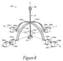
- FIG. 8is a perspective view of a slotted yoke joystick embodiment of a mechanical interface for the user object
- FIG. 9is a table summarizing rate control commands of the present invention.
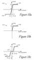
- FIGS. 10 a - care diagrammatic representations of restoring force profiles
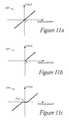
- FIGS. 11 a - care diagrammatic representations of restoring spring force profiles
- FIG. 12is a diagrammatic representation of a vector force
- FIGS. 13 a - bare diagrammatic representations of vibration force profiles
- FIG. 14is a table summarizing position control commands of the present invention.
- FIG. 15is a diagrammatic representation of a groove force profile
- FIG. 16is a diagrammatic representation of a barrier force profile
- FIGS. 17 a - 17 iare diagrammatic illustrations of a paddle and ball interaction controlled by a paddle command of the present invention.
- FIG. 18is a block diagram illustrating an implementation of the local microprocessor of the present invention for controlling a force feedback interface device with host commands containing force parameters;
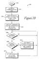
- FIG. 19is a flow diagram illustrating a host communication background process of FIG. 18 ;
- FIG. 20is a flow diagram illustrating a command process of FIG. 18 ;
- FIG. 21is a flow diagram illustrating a reporting process of FIG. 18 ;
- FIG. 22is a flow diagram illustrating force algorithm computation and actuator control process of FIG. 18 ;
- FIG. 23is a diagrammatic representation of force parameters and a sequence of force commands as used in the present invention.
- FIG. 1is a block diagram illustrating a generic control system 10 of the present invention for an interface device controlled by a host computer system.
- Control system 10includes a host computer system 12 and an interface device 14 .
- Host computer system 12is preferably a personal computer, such as an IBM-compatible or Macintosh personal computer, or a workstation, such as a SUN or Silicon Graphics workstation.
- the host computer systemcan a personal computer which operates under the MS-DOS or Windows operating systems in conformance with an IBM PC AT standard.
- host computer system 12can be one of a variety of home video game systems commonly connected to a television set, such as systems available from Nintendo, Sega, or Sony.
- home computer system 12can be a “set top box” which can be used, for example, to provide interactive television functions to users.
- host computer system 12implements a host application program with which a user 22 is interacting via peripherals and interface device 14 .
- the host application programcan be a video game, medical simulation, scientific analysis program, or even an operating system or other application program that utilizes force feedback.
- the host applicationprovides images to be displayed on a display output device, as described below, and/or other feedback, such as auditory signals.
- Host computer system 12preferably includes a host microprocessor 16 , random access memory (RAM) 17 , read-only memory (ROM) 19 , input/output (I/O) electronics 21 , a clock 18 , a display screen 20 , and an audio output device 21 .
- Host microprocessor 16can include a variety of available microprocessors from Intel, Motorola, or other manufacturers. Microprocessor 16 can be single microprocessor chip, or can include multiple primary and/or co-processors. Microprocessor preferably retrieves and stores instructions and other necessary data from RAM 17 and ROM 19 , as is well known to those skilled in the art.
- host computer system 12can receive sensor data or a sensor signal via a bus 24 from sensors of interface device 14 and other information.
- Microprocessor 16can receive data from bus 24 using I/O electronics 21 , and can use I/O electronics to control other peripheral devices.
- Host computer system 12can also output a “force command” to interface device 14 via bus 24 to cause force feedback for the interface
- Clock 18is a standard clock crystal or equivalent component used by host computer system 12 to provide timing to electrical signals used by microprocessor 16 and other components of the computer system. Clock 18 is accessed by host computer system 12 in the control process of the present invention, as described subsequently.
- Display screen 20is coupled to host microprocessor 16 by suitable display drivers and can be used to display images generated by host computer system 12 or other computer systems.
- Display screen 20can be a standard display screen or CRT, 3-D goggles, or any other visual interface.
- display screen 20displays images of a simulation or game environment. In other embodiments, other images can be displayed. For example, images describing a point of view from a first-person perspective can be displayed, as in a virtual reality simulation or game. Or, images describing a third-person perspective of objects, backgrounds, etc. can be displayed.
- a user 22 of the host computer 12 and interface device 14can receive visual feedback by viewing display screen 20 .
- computer 12may be referred as displaying computer “objects” or “entities”.
- objectsare not physical objects, but is a logical software unit collections of data and/or procedures that may be displayed as images by computer 12 on display screen 20 , as is well known to those skilled in the art.
- a cursor or a third-person view of a carmight be considered player-controlled computer objects that can be moved across the screen.
- a displayed, simulated cockpit of an aircraftmight also be considered an “object”, or the simulated aircraft can be considered a computer controlled “entity”.
- Audio output device 21such as speakers, is preferably coupled to host microprocessor 16 via amplifiers, filters, and other circuitry well known to those skilled in the art.
- Host processor 16outputs signals to speakers 21 to provide sound output to user 22 when an “audio event” occurs during the implementation of the host application program.
- Other types of peripheralscan also be coupled to host processor 16 , such as storage devices (hard disk drive, CD ROM drive, floppy disk drive, etc.), printers, and other input and output devices.
- An interface device 14is coupled to host computer system 12 by a bi-directional bus 24 .
- the bi-directional bussends signals in either direction between host computer system 12 and the interface device.
- busis intended to generically refer to an interface such as between host computer 12 and microprocessor 26 which typically includes one or more connecting wires or other connections and that can be implemented in a variety of ways, as described below.
- bus 24is a serial interface bus providing data according to a serial communication protocol.
- An interface port of host computer system 12such as an RS232 serial interface port, connects bus 24 to host computer system 12 .
- Other standard serial communication protocolscan also be used in the serial interface and bus 24 , such as RS-422, Universal Serial Bus (USB), MIDI, or other protocols well known to those skilled in the art.
- the USB standardprovides a relatively high speed serial interface that can provide force feedback signals in the present invention with a high degree of realism. USB can also source more power to drive peripheral devices. Since each device that accesses the USB is assigned a unique USB address by the host computer, this allows multiple devices to share the same bus.
- the USB standardincludes timing data that is encoded along with differential data. The USB has several useful features for the present invention, as described throughout this specification.
- An advantage of the present inventionis that low-bandwidth serial communication signals can be used to interface with interface device 14 , thus allowing a standard built-in serial interface of many computers to be used directly.
- a parallel port of host computer system 12can be coupled to a parallel bus 24 and communicate with interface device using a parallel protocol, such as SCSI or PC Parallel Printer Bus.
- bus 24can be connected directly to a data bus of host computer system 12 using, for example, a plug-in card and slot or other access of computer system 12 .
- the interface cardcan be implemented as an ISA, EISA, VESA local bus, PCI, or other well-known standard interface card which plugs into the motherboard of the computer and provides input and output ports connected to the main data bus of the computer.
- an additional bus 25can be included to communicate between host computer system 12 and interface device 14 . Since the speed requirement for communication signals is relatively high for outputting force feedback signals, the single serial interface used with bus 24 may not provide signals to and from the interface device at a high enough rate to achieve realistic force feedback.
- bus 24can be coupled to the standard serial port of host computer 12
- an additional bus 25can be coupled to a second port of the host computer system.
- many computer systemsinclude a “game port” in addition to a serial RS-232 port to connect a joystick or similar game controller to the computer.
- the two buses 24 and 25can be used simultaneously to provide a increased data bandwidth.
- microprocessor 26can send sensor signals to host computer 12 via a unidirectional bus 25 and a game port, while host computer 12 can output force feedback signals from a serial port to microprocessor 26 via a uni-directional bus 24 .
- Other combinations of data flow configurationscan be implemented in other embodiments.
- Interface device 14includes a local microprocessor 26 , sensors 28 , actuators 30 , a user object 34 , optional sensor interface 36 , an optional actuator interface 38 , and other optional input devices 39 .
- Interface device 14may also include additional electronic components for communicating via standard protocols on bus 24 .
- multiple interface devices 14can be coupled to a single host computer system 12 through bus 24 (or multiple buses 24 ) so that multiple users can simultaneously interface with the host application program (in a multi-player game or simulation, for example).
- multiple playerscan interact in the host application program with multiple interface devices 14 using networked host computers 12 , as is well known to those skilled in the art.
- Local microprocessor 26is coupled to bus 24 and is preferably included within the housing of interface device 14 to allow quick communication with other components of the interface device.
- Processor 26is considered “local” to interface device 14 , where “local” herein refers to processor 26 being a separate microprocessor from any processors in host computer system 12 .
- Localalso preferably refers to processor 26 being dedicated to force feedback and sensor I/O of interface device 14 , and being closely coupled to sensors 28 and actuators 30 , such as within the housing for interface device or in a housing coupled closely to interface device 14 .
- Microprocessor 26can be provided with software instructions to wait for commands or requests from computer host 16 , decode the command or request, and handle/control input and output signals according to the command or request.
- processor 26preferably operates independently of host computer 16 by reading sensor signals and calculating appropriate forces from those sensor signals, time signals, and a reflex process (also referred to as a “subroutine” or “force sensation process” herein) selected in accordance with a host command.
- Suitable microprocessors for use as local microprocessor 26include the MC68HC711E9 by Motorola and the PIC16C74 by Microchip, for example.
- Microprocessor 26can include one microprocessor chip, or multiple processors and/or co-processor chips. In other embodiments, microprocessor 26 can includes a digital signal processor (DSP) chip.
- DSPdigital signal processor
- Local memory 27such as RAM and/or ROM, is preferably coupled to microprocessor 26 in interface device 14 to store instructions for microprocessor 26 and store temporary and other data.
- Microprocessor 26can receive signals from sensors 28 and provide signals to actuators 30 of the interface device 14 in accordance with instructions provided by host computer 12 over bus 24 .
- a local clock 29can be coupled to the microprocessor 26 to provide timing data, similar to system clock 18 of host computer 12 ; the timing data might be required, for example, to compute forces output by actuators 30 (e.g., forces dependent on calculated velocities or other time dependent factors).
- timing data for microprocessor 26can be retrieved from USB signal.
- the USBhas a clock signal encoded with the data stream which can be used.
- the Isochronous (stream) mode of USBcan be used to derive timing information from the standard data transfer rate.
- the USBalso has a Sample Clock, Bus Clock, and Service Clock that also may be used.
- host computer 12can provide low-level force commands over bus 24 , which microprocessor 26 directly provides to actuators 30 . This embodiment is described in greater detail with respect to FIG. 4 .
- host computer system 12can provide high level supervisory commands to microprocessor 26 over bus 24 , and microprocessor 26 manages low level force control (“reflex”) loops to sensors 28 and actuators 30 in accordance with the high level commands. This embodiment is described in greater detail with respect to FIG. 5 .
- Microprocessor 26preferably also has access to an electrically erasable programmable ROM (EEPROM) or other memory storage device 27 for storing calibration parameters.
- the calibration parameterscan compensate for slight manufacturing variations in different physical properties of the components of different interface devices made from the same manufacturing process, such as physical dimensions.
- the calibration parameterscan be determined and stored by the manufacturer before the interface device 14 is sold, or optionally, the parameters can be determined by a user of the interface device.
- the calibration parametersare used by processor 26 to modify the input sensor signals and/or output force values to actuators 30 to provide approximately the same range of forces on object 34 in a large number of manufactured interface devices 14 .
- the implementation of calibration parametersis well-known to those skilled in the art.
- Microprocessor 26can also receive commands from any other input devices included on interface apparatus 14 and provides appropriate signals to host computer 12 to indicate that the input information has been received and any information included in the input information. For example, buttons, switches, dials, or other input controls on interface device 14 or user object 34 can provide signals to microprocessor 26 .
- sensors 28 , actuators 30 , and microprocessor 26 , and other related electronic componentsare included in a housing for interface device 14 , to which user object 34 is directly or indirectly coupled.
- microprocessor 26 and/or other electronic components of interface device 14can be provided in a separate housing from user object 34 , sensors 28 , and actuators 30 .
- additional mechanical structuresmay be included in interface device 14 to provide object 34 with desired degrees of freedom. Some embodiments of such mechanisms are described with reference to FIGS. 7-12 .
- Sensors 28sense the position, motion, and/or other characteristics of a user object 34 of the interface device 14 along one or more degrees of freedom and provide signals to microprocessor 26 including information representative of those characteristics. Examples of embodiments of user objects and movement within provided degrees of freedom are described subsequently with respect to FIGS. 7 and 8 .
- a sensor 28is provided for each degree of freedom along which object 34 can be moved.
- a single compound sensorcan be used to sense position or movement in multiple degrees of freedom.
- An example of sensors suitable for several embodiments described hereinare digital optical encoders, which sense the change in position of an object about a rotational axis and provide digital signals indicative of the change in position.
- the encoderresponds to a shaft's rotation by producing two phase-related signals in the rotary degree of freedom.
- Linear optical encoderssimilarly sense the change in position of object 34 along a linear degree of freedom, and can produces the two phase-related signals in response to movement of a linear shaft in the linear degree of freedom.
- Either relative or absolute sensorscan be used.
- relative sensorsonly provide relative angle information, and thus usually require some form of calibration step which provide a reference position for the relative angle information.
- the sensors described hereinare primarily relative sensors. In consequence, there is an implied calibration step after system power-up wherein a sensor's shaft is placed in a known position within interface device and a calibration signal is provided to the system to provide the reference position mentioned above.
- a suitable optical encoderis the “Softpot” from U.S. Digital of Vancouver, Wash.
- Sensors 28provide an electrical signal to an optional sensor interface 36 , which can be used to convert sensor signals to signals that can be interpreted by the microprocessor 26 and/or host computer system 12 .
- sensor interface 36receives the two phase-related signals from a sensor 28 and converts the two signals into another pair of clock signals, which drive a bi-directional binary counter. The output of the binary counter is received by microprocessor 26 as a binary number representing the angular position of the encoded shaft.
- Such circuits, or equivalent circuitsare well known to those skilled in the art; for example, the Quadrature Chip LS7166 from Hewlett Packard, Calif. performs the functions described above.
- Each sensor 28can be provided with its own sensor interface, or one sensor interface may handle data from multiple sensors.
- the electronic interface described in parent patent application Ser. No. 08/092,974describes a sensor interface including a separate processing chip dedicated to each sensor that provides input data.
- microprocessor 26can perform these interface functions without the need for a separate sensor interface 36 .
- the position value signalscan be used by microprocessor 26 and are also sent to host computer system 12 which updates the host application program and sends force control signals as appropriate. For example, if the user moves a steering wheel object 34 , the computer system 12 receives position and/or other signals indicating this movement and can move a displayed point of view of the user as if looking out a vehicle and turning the vehicle.
- Other interface mechanismscan also be used to provide an appropriate signal to host computer system 12 .
- sensor signals from sensors 28can be provided directly to host computer system 12 , bypassing microprocessor 26 .
- sensor interface 36can be included within host computer system 12 , such as on an interface board or card.
- an analog sensorcan be used instead of digital sensor for all or some of the sensors 28 .
- a strain gaugecan be connected to measure forces on object 34 rather than positions of the object.
- velocity sensors and/or accelerometerscan be used to directly measure velocities and accelerations on object 34 .
- Analog sensorscan provide an analog signal representative of the position/velocity/acceleration of the user object in a particular degree of freedom.
- An analog to digital convertercan convert the analog signal to a digital signal that is received and interpreted by microprocessor 26 and/or host computer system 12 , as is well known to those skilled in the art. The resolution of the detected motion of object 34 would be limited by the resolution of the ADC. However, noise can sometimes mask small movements of object 34 from an analog sensor, which can potentially mask the play that is important to some embodiments of the present invention (described subsequently).
- interface circuitry 36can also be used.
- an electronic interfaceis described in U.S. patent application Ser. No. 08/092,974, entitled “3-D Mechanical Mouse”, previously incorporated herein.
- the interfaceallows the position of the mouse or stylus to be tracked and provides force feedback to the stylus using sensors and actuators.
- Sensor interface 36can include angle determining chips to pre-process angle signals reads from sensors 28 before sending them to the microprocessor 26 .
- a data bus plus chip-enable linesallow any of the angle determining chips to communicate with the microprocessor.
- a configuration without angle-determining chipsis most applicable in an embodiment having absolute sensors, which have output signals directly indicating the angles without any further processing, thereby requiring less computation for the microprocessor 26 and thus little if any pre-processing. If the sensors 28 are relative sensors, which indicate only the change in an angle and which require further processing for complete determination of the angle, then angle-determining chips are more appropriate.
- Actuators 30transmit forces to user object 34 of the interface device 14 in one or more directions along one or more degrees of freedom in response to signals received from microprocessor 26 .
- an actuator 30is provided for each degree of freedom along which forces are desired to be transmitted.
- Actuators 30can include two types: active actuators and passive actuators.
- Active actuatorsinclude linear current control motors; stepper motors, pneumatic/hydraulic active actuators, and other types of actuators that transmit a force to move an object.
- active actuatorscan drive a rotational shaft about an axis in a rotary degree of freedom, or drive a linear shaft along a linear degree of freedom.
- Active transducers of the present inventionare preferably bi-directional, meaning they can selectively transmit force along either direction of a degree of freedom.
- DC servo motorscan receive force control signals to control the direction and torque (force output) that is produced on a shaft.
- the motorsmay also include brakes which allow the rotation of the shaft to be halted in a short span of time.
- active motorscan also be used, such as a stepper motor controlled with pulse width modulation of an applied voltage, pneumatic/hydraulic actuators, a torquer (motor with limited angular range), or a voice coil actuator, which are well known to those skilled in the art.
- Passive actuatorscan also be used for actuators 30 .
- Magnetic particle brakes, friction brakes, or pneumatic/hydraulic passive actuatorscan be used in addition to or instead of a motor to generate a damping resistance or friction in a degree of motion.
- An alternate preferred embodiment only including passive actuatorsmay not be as realistic as an embodiment including motors; however, the passive actuators are typically safer for a user since the user does not have to fight generated forces.
- Passive actuatorstypically can only provide bi-directional resistance to a degree of motion.
- a suitable magnetic particle brake for interface device 14is available from Force Limited, Inc. of Santa Monica, Calif.
- sensors 28 and actuators 30can be included together as a sensor/actuator pair transducer.
- a suitable transducer for the present invention including both an optical encoder and current controlled motoris a 20 W basket wound servo motor manufactured by Maxon.
- Actuator interface 38can be optionally connected between actuators 30 and microprocessor 26 .
- Interface 38converts signals from microprocessor 26 into signals appropriate to drive actuators 30 .
- Interface 38can include power amplifiers, switches, digital to analog controllers (DACs), and other components.
- An example of an actuator interface for active actuatorsis described with reference to FIG. 2 .
- An example of an actuator interface for passive actuatorsis described with reference to FIG. 3 .
- interface 38 circuitrycan be provided within microprocessor 26 or in actuators 30 .
- Other input devices 39can optionally be included in interface device 14 and send input signals to microprocessor 26 .
- Such input devicescan include buttons, dials, switches, or other mechanisms.
- user object 34is a joystick
- other input devicescan include one or more buttons provided, for example, on the joystick handle or base and used to supplement the input from the user to a game or simulation. The operation of such input devices is well known to those skilled in the art.
- Power supply 40can optionally be coupled to actuator interface 38 and/or actuators 30 to provide electrical power. Active actuators typically require a separate power source to be driven. Power supply 40 can be included within the housing of interface device 14 , or can be provided as a separate component, for example, connected by an electrical power cord.
- interface device 14can draw power from the USB and thus have no need for power supply 40 .
- This embodimentis most applicable to a device 14 having passive actuators 30 , since passive actuators require little power to operate. Active actuators tend to require more power than can be drawn from USB, but this restriction can be overcome in a number of ways.
- One wayis to configure interface 14 to appear as more than one peripheral to host computer 12 ; for example, each provided degree of freedom of user object 34 can be configured as a different peripheral and receive its own allocation of power. This would allow host 12 to allocate more power to interface device 14 .
- power from the USBcan be stored and regulated by interface device 14 and thus used when needed to drive actuators 30 .
- powercan be stored over time and then immediately dissipated to provide a jolt force to the user object 34 .
- a capacitor circuitfor example, can store the energy and dissipate the energy when enough power has been stored.
- Microprocessormay have to regulate the output of forces to assure that time is allowed for power to be stored.
- This power storage embodimentcan also be used in non-USB embodiments of interface device 14 to allow a smaller power supply 40 to be used.
- Safety switch 41is preferably included in interface device to provide a mechanism to allow a user to override and deactivate actuators 30 , or require a user to activate actuators 30 , for safety reasons. Certain types of actuators, especially active actuators such as motors, can pose a safety issue for the user if the actuators unexpectedly move user object 34 against the user with a strong force. In addition, if a failure in the control system 10 occurs, the user may desire to quickly deactivate the actuators to avoid any injury. To provide this option, safety switch 41 is coupled to actuators 30 . In the preferred embodiment, the user must continually activate or close safety switch 41 during operation of interface device 14 to activate the actuators 30 .
- safety switchis deactivated (opened), power from power supply 40 is cut to actuators 30 (or the actuators are otherwise deactivated) as long as the safety switch is deactivated.
- a preferred embodiment of safety switchis an optical switch located on user object 34 (such as a joystick) or on a convenient surface of a housing enclosing interface device 14 . When the user covers the optical switch with a hand or finger, the sensor of the switch is blocked from sensing ambient light, and the switch is closed. The actuators 30 thus will function as long as the user covers the switch.
- Other types of safety switches 41can be provided in other embodiments. For example, an electrostatic contact switch can be used to sense contact, a button or trigger can be pressed, or a different type of sensor switch can be used.
- User object 34is preferably a device or article that may be grasped or otherwise contacted or controlled by a user and which is coupled to interface device 14 .
- graspit is meant that users may releasably engage a grip portion of the object in some fashion, such as by hand, with their fingertips, or even orally in the case of handicapped persons.
- the user 22can manipulate and move the object along provided degrees of freedom to interface with the host application program the user is viewing on display screen 20 .
- Object 34can be a joystick, mouse, trackball, stylus, steering wheel, medical instrument (laparoscope, catheter, etc.), pool cue, hand grip, knob, button, or other article.
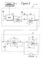
- FIG. 2is a schematic diagram illustrating an example of an actuator interface 38 for an active actuator 30 of interface device 14 .
- actuator 30is a linear current controlled servo motor.
- Actuator interface 38includes a DAC circuit 44 and a power amplifier circuit 46 .
- DAC circuit 44is coupled to microprocessor 26 and preferably receives a digital signal representing a force value from the microprocessor 26 .
- DAC 48is suitable for converting an input digital signal to an analog voltage that is output to power amplifier circuit 46 .
- a suitable DAC 48is a parallel DAC, such as the DAC1220 manufactured by National Semiconductor, which is designed to operate with external generic op amp 50 .
- Op amp 50for example, outputs a signal from zero to ⁇ 5 volts proportional to the binary number at its input.
- Op amp 52is an inverting summing amplifier that converts the output voltage to a symmetrical bipolar range.
- Op amp 52produces an output signal between ⁇ 2.5 V and +2.5 V by inverting the output of op amp 50 and subtracting 2.5 volts from that output; this output signal is suitable for power amplification in amplification circuit 46 .
- DAC circuit 44is intended as one example of many possible circuits that can be used to convert a digital signal to a desired analog signal.
- Power amplifier circuit 46receives an analog low-power control voltage from DAC circuit 44 and amplifies the voltage to control actuators 30 .
- Actuator 30can be a high-power, current-controlled servo motor 30 .
- the input voltagecontrols a transconductance stage composed of amplifier 54 and several resistors.
- the transconductance stageproduces an output current proportional to the input voltage to drive motor 30 while drawing very little current from the input voltage source.
- the second amplifier stageincluding amplifier 56 , resistors, and a capacitor C, provides additional current capacity by enhancing the voltage swing of the second terminal 57 of motor 30 .
- circuit 46is intended as one example of many possible circuits that can be used to amplify voltages to drive active actuators 30 .
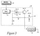
- FIG. 3is a schematic diagram illustrating an example of an actuator interface 38 ′ that can be used in conjunction with passive actuators.
- Interface 38 ′is suitable for use with passive actuators (dampers) that are controlled with an analog voltage, such as magnetic particle brakes or a variable solenoid used with the fluid controlled passive dampers of parent application Ser. No. 08/489,068.
- Interface 38 ′includes a DAC circuit 44 , amplifier 60 , transistor 62 , and voltage protector 64 .
- DAC circuit 44is coupled to microprocessor 26 and receives a digital signal from the computer system representing a resistive force value to be applied to user object 34 .
- DAC circuit 44converts the digital signal voltages to analog voltages which are then output to amplifier 60 .
- a suitable DACis the MAX530ACNG manufactured by Maxim, or DAC circuit 44 as described above with reference to FIG. 2 .
- Amplifier 60receives the analog voltage from DAC 44 on a positive terminal and scales the voltage signal to a range usable by actuator 30 .
- Amplifier 60can be implemented as an operational amplifier or the like.
- Transistor 62is coupled to the output of amplifier 60 and preferably operates as an amplifier to provide increased output current to actuator 30 .
- Resistor R 1is coupled between amplifier 60 and the emitter of transistor 62
- resistor R 2is coupled between amplifier 60 and ground.
- resistors R 1 and R 2can have values of 180 k_and 120 k_, respectively, and provide the proper biasing in the circuit.
- Voltage protector 64is coupled to the emitter of transistor 62 and provides protection from voltage spikes when using inductive loads.
- Suitable passive actuators 30 for use with this circuitryincludes variable solenoids or magnetic particle brakes.
- a separate DAC and amplifiercan be used for each actuator 30 implemented in the interface apparatus so the microprocessor 26 and/or host computer system 12 can control each actuator separately for each provided degree of freedom.
- Interface 38 ′is intended as one example of many possible circuits that can be used to interface a computer system to actuators.
- an on/off signalmight only be needed, for example, for a solenoid driving an on/off valve of a fluid-controlled actuator as described in co-pending patent application Ser. No. 08/489,068 and below in FIG. 10 .
- a transistorcan be electrically coupled to microprocessor 26 at its base terminal to operate as an electrical switch for controlling the activation of a solenoid in the on/off actuator 30 .
- a force signalsuch as a TTL logic signal can be sent to control the transistor to either allow current to flow through the solenoid to activate it and allow free movement of object 43 , or to allow no current to flow to deactivate the solenoid and provide resistance to movement.
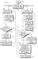
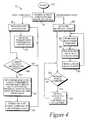
- FIG. 4is a flow diagram illustrating a first embodiment of a method 70 for controlling a force feedback interface device of the present invention.
- Method 70is directed to a “host-controlled” embodiment, in which host computer system 12 provides direct, low-level force commands to microprocessor 26 , and the microprocessor directly provides these force commands to actuators 30 to control forces output by the actuators.
- the host controlled modeis suitable for embodiments using a USB communication interface.
- Data ratesare sufficiently high to allow the host to communicate at 500 Hz or greater and provide realistic force feedback to the user object 34 .
- the USB Isochronous Data Transfer mode of USBis suitable to provide the necessary high data rate.
- step 74host computer system 12 and interface device 14 are powered up, for example, by a user activating power switches.
- step 74the process 70 branches into two parallel (simultaneous) processes. One process is implemented on host computer system 12 , and the other process is implemented on local microprocessor 26 . These two processes branch out of step 74 in different directions to indicate this simultaneity.
- step 76is first implemented, in which an application program is processed or updated.
- This applicationcan be a simulation, video game, scientific program, or other program. Images can be displayed for a user on output display screen 20 and other feedback can be presented, such as audio feedback.
- step 78is implemented, where sensor data is received by the host computer from local microprocessor 26 .
- the local processor 26continually receives signals from sensors 28 , processes the raw data, and sends processed sensor data to host computer 12 , Alternatively, local processor 26 sends raw data directly to host computer system 12 .
- Sensor datacan include position values, velocity values, and/or acceleration values derived from the sensors 28 which detect motion of object 34 in one or more degrees of freedom.
- any other data received from other input devices 39can also be received by host computer system 12 as sensor data in step 78 , such as signals indicating a button on interface device 14 has been activated by the user.
- sensor dataalso can include a history of values, such as position values recorded previously and stored in order to calculate a velocity.
- Step 78After sensor data is read in step 78 , the process returns to step 76 , where the host computer system 12 can update the application program in response to the user's manipulations of object 34 and any other user input received in step 78 as well as determine if forces need to be applied to object 34 in the parallel process.
- Step 78is implemented in a continual loop of reading data from local processor 26 .
- the second branch from step 76is concerned with the process of the host computer determining force commands to provide force feedback to the user manipulating object 34 .
- These commandsare described herein as “low-level” force commands, as distinguished from the “high-level” or supervisory force commands described in the embodiment of FIG. 5 .
- a low level force commandinstructs an actuator to output a force of a particular magnitude.
- the low level commandtypically includes a magnitude force value, e.g., equivalent signal(s) to instruct the actuator to apply a force of a desired magnitude value.
- Low level force commandsmay also designate a direction of force if an actuator can apply force in a selected direction, and/or other low-level information as required by an actuator.
- step 80the host computer system checks if a change in the force applied to user object 34 is required. This can be determined by several types of criteria, the most important of which are the sensor data read by the host computer in step 78 , timing data, and the implementation or “events” of the application program updated in step 76 .
- the sensor data read in step 78informs the host computer 12 how the user is interacting with the application program. From the position of object 34 sensed over time, the host computer system 12 can determine when forces should be applied to the object. For example, if the host computer is implementing a video game application, the position of a computer generated object within the game may determine if a change in force feedback is called for.
- the position of the user object joystickdetermines if the race car is moving into a wall and thus if a collision force should be generated on the joystick.
- the velocity and/or acceleration of the user objectcan influence whether a change in force on the object is required.
- the velocity of a user object joystick in a particular degree of freedommay determine if a tennis ball is hit and this if an appropriate force should be applied to the joystick.
- other inputsuch as a user activating buttons or other controls on interface device 14 , can change the forces required on object 34 depending on how those controls have been programmed to affect the application program.
- a game application programmay (perhaps randomly) determine that another object in the game is going to collide with an object controlled by the user, regardless of the position data of the user object 34 . Forces should thus be applied to the user object dependent on this collision event to simulate an impact. Forces can be required on the user object depending on a combination of such an event and the sensor data read in step 78 .
- Other parameters in the application programcan determine if a change in force to the user object is necessary, such as other input devices or user interface devices connected to host computer system 12 and inputting data to the application program (other interface devices can be directly connected, connected remotely through a network, etc.).
- step 80If no change in force is currently required in step 80 , then the process returns to step 76 to update the host application and return to step 80 to again check until such a change in force is required.
- step 82is implemented, in which host computer 12 determines appropriate low-level force commands to be sent to the actuators 30 of interface device 14 , these force commands being dependent on a selected force sensation process, sensor data, the host application, and the clock 18 .
- the low-level force commandscan be determined, in part, from a selected force sensation process.
- a “reflex process” or “force sensation process”, as referred to herein,is a set of instructions for providing force commands dependent on other parameters, such as sensor data read in step 78 and timing data from clock 18 .
- force sensation processescan include several different types of steps and/or instructions.
- One type of instructionis a force algorithm, which includes an equation that host computer 12 can use to calculate or model a force value based on sensor and timing data.
- Several types of algorithmscan be used. For example, algorithms in which force varies linearly (or nonlinearly) with the position of object 34 can be used to provide a simulated force like a spring.
- Algorithms in which force varies linearly (or nonlinearly) with the velocity of object 34can be also used to provide a simulated damping force or other forces.
- Algorithms in which force varies linearly (or nonlinearly) with the acceleration of object 34can also be used to provide, for example, a simulated inertial force on a mass (for linear variation) or a simulated gravitational pull (for nonlinear variation).
- Several types of simulated forces and the algorithms used to calculate such forcesare described in “Perceptual Design of a Virtual Rigid Surface Contact,” by Louis B. Rosenberg, Center for Design Research, Stanford University, Report number AL/CF-TR-1995-0029, April 1993, which is incorporated by reference herein.
- the velocity and accelerationcan be provided in a number of different ways.
- the sensor data read by host computer 12 in step 78can include position data, velocity data, and acceleration data.
- the velocity and acceleration datawas calculated previously by microprocessor 26 and then provided to the host computer 12 .
- the host computercan thus use the velocity and acceleration data directly in an algorithm to calculate a force value.
- the sensor data read in step 78includes position data and no velocity or acceleration data, so that host computer 12 is required to calculate the velocity and acceleration from the position data. This can be accomplished by recording a number of past position values, recording the time when each such position value was received using the system clock 18 , and calculating a velocity and/or acceleration from such data.
- a kinematic equation which calculates a force based on the velocity of the user object multiplied by a damping constantcan be used to determine a damping force on the user object.
- This type of equationcan simulate motion of object 34 along one degree of freedom through a fluid or similar material.
- a procedure for calculating a damping force on object 34is described in co-pending patent application Ser. No. 08/400,233, filed Mar. 3, 1995 entitled “Method and Apparatus for Providing Passive Force Feedback”, which is hereby incorporated by reference herein.
- a damping constantcan first be selected which indicates the degree of resistance that object 34 experiences when moving through a simulated material, such as a liquid, where a greater number indicates greater resistance.
- waterwould have a lower damping constant than oil or syrup.
- the host computerrecalls the previous position of user object 34 (along a particular degree of freedom), examine the current position of the user object, and calculate the difference in position. From the sign (negative or positive) of the difference, the direction of the movement of object 34 can also be determined. The force is then set equal to the damping constant multiplied by the change in position. Commands that controlled an actuator based on this algorithm would produce a force proportional to the user object's motion to simulate movement through a fluid. Movement in other mediums, such as on a bumpy surface, on an inclined plane, etc., can be simulated in a similar fashion using different methods of calculating the force.
- the determination of force commandsis preferably influenced by timing data accessed from system clock 18 .
- the velocity of the user object 34is determined by calculating the different of positions of the user object and multiplying by the damping constant. This calculation assumes a fixed time interval between data points, i.e., it is assumed that the position data of the object 34 is received by host computer 12 in regular, predetermined time intervals. However, this may not actually occur due to different processing speeds of different computer platforms or due to processing variations on a single host microprocessor 16 , such as due to multitasking. Therefore, in the present invention, the host computer preferably accesses clock 12 to determine how much time has actually elapsed since the last position data was received.
- the host computercould take the difference in position and divide it by a time measure to account for differences in timing.
- the host computercan thus use the clock's timing data in the modulation of forces and force sensations to the user.
- Timing datacan be used in other algorithms and force sensation processes of the present invention to provide repeatable and consistent force feedback regardless of type of platform or available processing time on host computer 12 .
- Other instructionscan also be included in a force sensation process.
- conditionscan be included to provide forces only in desired directions or under other particular circumstances.
- forcesshould be applied in only one direction (uni-directional).
- bi-directional resistance forcescan be applied.
- conditionscan be included in the virtual obstruction force sensation process.
- An example of such conditions in a virtual obstruction force sensation processis described with respect to FIG. 12 .
- a “null” reflex processcan be available that instructs host computer 12 (or microprocessor 26 in the embodiment of FIG. 5 ) to issue a low level command or force values to provide zero forces (i.e. remove all forces) on user object 34 .
- Another type of force sensation processdoes not use algorithms to model a force, but instead uses force values that have been previously calculated or sampled and stored as a digitized “force profile” in memory or other storage device. These force values may have been previously generated using an equation or algorithm as described above, or provided by sampling and digitizing forces. For example, to provide a particular force sensation to the user, host computer 12 can be instructed by a force sensation process to retrieve successive force values from a certain storage device, such as RAM, ROM, hard disk, etc. These force values can be sent directly to an actuator in a low-level command to provide particular forces without requiring host computer 12 to calculate the force values.
- previously-stored force valuescan be output with respect to other parameters to provide different types of forces and force sensations from one set of stored force values. For example, using system clock 18 , the stored force values can be output in sequence according to a particular time interval that can vary depending on the desired force. Or, different retrieved force values can be output depending on the current position of user object 34 .
- Host computer 12can determine a force command in step 82 according to a newly-selected reflex process, or to a previously selected reflex process. For example, if this is a second or later iteration of step 82 , the same reflex process as in the previous iteration can be again implemented if parameters (such as the position of object 34 ) allow it, as determined by the host application program.
- the force command determined in step 82can also depend on instructions that check for other parameters. These instructions can be included within or external to the above-described reflex processes.
- One such parameterare values provided by the implemented host application program (if any).
- the application programmay determine that a particular force command should be output or reflex process implemented based on events occurring within the application program or other instructions. Force commands or values can be provided by the host application program independently of sensor data. Also, the host application program can provide its own particular position, velocity, and/or acceleration data to a selected reflex process to calculate or provide a force that is not based on the manipulation of user object 34 , but is provided to simulate an event in the application program. Such events may include collision events, such as occur when a user-controlled computer image impacts a virtual surface or structure.
- other input devices connected to host computer 12can influence events and, therefore, the forces applied to user object 34 .
- the sensor data from multiple interface devices 14 connected to a single host computercan influence the forces felt on other connected interface devices by influencing events and computer-controlled images/objects of the host application program.
- the force commands determined in step 82can be based on other inputs to host computer 12 , such as activations of buttons or other input devices in (or external to) interface device 14 .
- a particular application programmight require that a force be applied to a joystick whenever a user presses a fire button on the joystick.
- typical haptic sensationsmay include a virtual damping (described above), a virtual obstruction, and a virtual texture.
- Virtual obstructionsare provided to simulate walls, obstructions, and other uni-directional forces in a simulation, game, etc.
- a usermoves a computer image into a virtual obstruction with a joystick, the user then feels a physical resistance as he or she continues to move the joystick in that direction. If the user moves the object away from the obstruction, the uni-directional force is removed.
- the useris given a convincing sensation that the virtual obstruction displayed on the screen has physical properties.
- virtual texturescan be used to simulate a surface condition or similar texture.
- the host computersends a rapid sequence of commands to repetitively 1) apply resistance along that axis, and 2) to then immediately apply no resistance along that axis, as according to a reflex process. This frequency is based upon the travel of the joystick handle and is thus correlated with spatial position.
- the userfeels a physical sensation of texture, which can be described as the feeling of dragging a stick over a grating.
- a low-level force command determined in step 82is output to microprocessor 26 over bus 24 .
- This force commandtypically includes a force value that was determined in accordance with the parameters described above.
- the force commandcan be output as an, actual force signal that is merely relayed to an actuator 30 by microprocessor 26 ; or, the force command can be converted to an appropriate form by microprocessor 26 before being sent to actuator 30 .
- the low-level force commandpreferably includes information indicating to microprocessor 26 which actuators are to receive this force value (if multiple actuators are included on interface device 14 ). The process then returns to step 76 to process/update the host application program.
- step 80the host computer checks if a different force command should be output as determined by the parameters described above. If so, a new force command is determined and output in step 84 . If no change of force is required, host computer 12 does not issue another command, since microprocessor 26 can continues to output the previous force command to actuators 30 (alternatively, host computer 12 can continue to output commands, even if no change of force is required). Subsequent force commands output in step 84 can be determined in accordance with the same reflex process, or a different reflex process, depending on the parameters of step 82 .
- the host computer 12preferably synchronizes any appropriate visual feedback, auditory feedback, or other feedback related to the host application with the application of forces on user object 34 .
- the onset or start of visual eventssuch as an object colliding with the user on display screen 20
- the onsets visual events and force eventsare preferably occur within about 30 milliseconds (ms) of each other. This span of time is the typical limit of human perceptual ability to perceive the events as simultaneous. If the visual and force events occur outside this range, then a time lag between the events can usually be perceived.
- the output of auditory signalsare preferably output synchronized with the onset of output forces that correspond to/complement those auditory events.
- the onsets of these eventsoccur preferably within about 30 ms of each other.
- host computer system 12can output sounds of an explosion from speakers 21 as close in time as possible to the forces felt by the user from that explosion in a simulation.
- the magnitude of the soundis in direct (as opposed to inverse) proportion to the magnitude of the forces applied to user object 34 .
- a low sound of an explosion in the far (virtual) distancecan cause a small force on user object 34
- a large, “nearby” explosionmight cause a loud sound to be output by the speakers and a correspondingly large force to be output on object 34 .
- the local microprocessor 26implements the process branching from step 74 and starting with step 86 in parallel with the host computer process described above.
- step 86the interface device 14 is activated. For example, signals can be sent between host computer 12 and interface device 14 to acknowledge that the interface device is now active.
- two processesbranch to indicate that there are two processes running simultaneously (multi-tasking) on local processor 26 .
- step 88is implemented, in which the processor 26 reads raw data (sensor readings) from sensors 28 .
- raw datapreferably includes position values describing the position of the user object along provided degrees of freedom.
- sensors 28are relative sensors that provide position values describing the change in position since the last position read.
- Processor 26can determine the absolute position by measuring the relative position from a designated reference position.
- sensors 28can include velocity sensors and accelerometers for providing raw velocity and acceleration values of object 34 .
- the raw data read in step 88can also include other input, such as from an activated button or other control 39 of interface device 14 .
- processor 26processes the received raw data into sensor data, if applicable.
- this processingincludes two steps: computing velocity and/or acceleration values from raw position data (if velocity and/or acceleration are needed to compute forces), and filtering the computed velocity and acceleration data.
- the velocity and acceleration valuesare computed from raw position data received in step 88 and stored position and time values.
- processor 26stores a number of position values and time values corresponding to when the position values were received.
- Processor 26can use its own or a local system clock (not shown in FIG. 1 ) to determine the timing data.
- the velocity and accelerationcan be computed using the stored position data and timing data, as is well known to those skilled in the art.
- the sensor data in the described embodimentincludes position, velocity, acceleration, and other input data.
- circuitry that is electrically coupled to but separate from processor 26can receive the raw data and determine velocity and acceleration.
- ASICapplication-specific integrated circuit
- discrete logic circuitrycan use counters or the like to determine velocity and acceleration to save processing time on microprocessor 26 .
- step 90can be omitted, and the processor 26 can provide raw position data to host computer 12 (and other input data from other input devices 39 ). This would require host computer 12 to filter and compute velocity and acceleration from the position data. Thus, it is preferred that processor 26 do this processing to reduce the amount of processing performed on host computer 12 .
- the filteringcan be performed on host computer 12 while the velocity and acceleration calculation can be performed on the processor 26 .
- the calculation of velocity and/or accelerationcan be omitted.
- step 91is implemented, in which the processor 26 sends the processed sensor data to the host computer 12 via bus 24 . The process then returns to step 88 to read raw data. Steps 88 , 90 and 91 are thus continuously implemented to provide current sensor data to host computer system 12 .
- the second branch from step 86is concerned with processor 26 controlling the actuators 30 to provide forces calculated by host computer 12 to object 34 .
- the second branchstarts with step 92 , in which processor 26 checks if a low-level force command has been received from host computer 12 over bus 24 . If not, the process continually checks for such a force command.
- step 94is implemented, in which processor 26 outputs a low-level processor force command to the designated actuators to set the output force to the desired magnitude, direction, etc.
- This force commandmay be equivalent to the received low-level command from the host computer, or, the processor 26 can optionally convert the force command to an appropriate form usable by actuator 30 (or actuator interface 38 can perform such conversion).
- the processthen returns to step 92 to check for another force command from the host computer 12 .
- FIG. 5is a flow diagram illustrating a second embodiment of a method 100 for controlling force feedback interface device 14 of the present invention.
- Method 100is directed to a “reflex” embodiment, in which host computer system 12 provides only high-level supervisory force commands (“host commands”) to microprocessor 26 , while the microprocessor independently determines and provides low-level force commands (force values) to actuators 30 as an independent “reflex” to control forces output by the actuators.
- host commandshigh-level supervisory force commands
- actuators 30as an independent “reflex” to control forces output by the actuators.
- the process of FIG. 5is suitable for low speed communication interfaces, such as a standard RS-232 serial interface.
- the embodiment of FIG. 5is also suitable for high speed communication interfaces such as USB, since the local microprocessor relieves computational burden from host processor 16 .
- this embodimentcan provide a straightforward command protocol, an example of which is described with respect to FIGS. 9 and 14 , and which allow software developers to easily provide force feedback in a host application.
- the slower “interrupt data transfers” mode of USBcan be used.
- step 104host computer system 12 and interface device 14 are powered up, for example, by a user activating power switches.
- step 104the process 100 branches into two parallel processes. One process is implemented on host computer system 12 , and the other process is implemented on local microprocessor 26 .
- step 106is first implemented, in which an application program is processed.
- This applicationcan be a simulation, video game, scientific program, or other program. Images can be displayed for a user on output display screen 20 and other feedback can be presented, such as audio feedback.
- step 106Two branches exit step 106 to indicate that there are two processes running simultaneously (multi-tasking, etc.) on host computer system 12 .
- step 108is implemented, where sensor data from the user object is received by the host computer from local microprocessor 26 .
- host computer system 12receives either raw data (e.g., position data and no velocity or acceleration data) or processed sensor data (position, velocity and/or acceleration data) from microprocessor 26 .
- any other data received from other input devices 39can also be received by host computer system 12 from microprocessor 26 in step 108 , such as signals indicating a button on interface device 14 has been pressed by the user.
- the host computerdoes not calculate force values from the received sensor data in step 108 . Rather, host computer 12 monitors the sensor data to determine when a change in the type of force is required. This is described in greater detail below. Of course, host computer 12 also uses the sensor data as input for the host application to update the host application accordingly.
- Step 108is then implemented again in a continual loop of receiving sets of sensor data from local processor 26 .
- the host computerdoes not need to directly control actuators based on sensor data, the sensor data can be provided at a much lower speed.
- the host computerupdates the host application and images on display screen 20 in response to sensor data, the sensor data need only be read at 60-70 Hz (the refresh cycle of a typical display screen) compared to the much higher rate of about 500-1000 Hz (or greater) needed to realistically provide low-level force feedback signals from sensor signals.
- Host computer 12also preferably synchronizes visual, audio, and force events similarly as described above with reference to FIG. 4 .
- the second branch from step 106is concerned with the process of the host computer determining high-level force commands (“host commands”) to provide force feedback to the user manipulating object 34 .
- the second branchstarts with step 110 , in which the host computer system checks if a change in the type of force applied to user object 34 is required.
- the “type” of forceis a force sensation or profile produced by a particular reflex process or force value which the local microprocessor 26 can implement independently of the host computer.
- the host computer 12determines whether a change in the type of force is required depending on the sensor data read by the host computer in step 108 and depending on the events of the application program updated in step 106 . As explained with reference to FIG.
- the sensor datainforms the host computer when forces should be applied to the object based on the object's current position, velocity, and/or acceleration.
- the user's manipulations of object 34may have caused a new type of force to required. For example, if the user is moving a virtual race car within a virtual pool of mud in a video game, a damping type of force should be applied to the object 34 as long as the race car moves within the mud. Thus, damping forces need to be continually applied to the object, but no change in the type of force is required. When the race car moves out of the pool of mud, a new type of force (i.e. a removal of damping force in this case) is required.
- the events of the application programmay also require a change in the type of force applied. For example, if the user's car is traveling through mud and another car collides into the user's car, then a new type of force (collision force) should be applied to the user object. Forces may be required on the user object depending on a combination of an application event and the sensor data read in step 108 . Also, other input, such as a user activating buttons or other input devices 39 on interface device 14 , can change the type of forces required on object 34 .
- step 112is implemented, in which host computer 12 determines an appropriate host command to send to microprocessor 26 .
- the available host commands for host computer 12may each correspond to an associated reflex process implemented by microprocessor 26 .
- host commands to provide a damping force, a spring force, a gravitational pull, a bumpy surface force, a virtual obstruction force, and other forcescan be available to host computer 12 .
- These host commandscan also include a designation of the particular actuators 30 or degrees of freedom which are to apply this desired force on object 34 .
- the host commandscan also include other command parameter information which might vary the force produced by a particular reflex process. For example, a damping constant can be included in a host command to designate a desired amount of damping force.
- the host commandmay also preferably override the reflex operation of the processor 26 and include low-level force values.
- a preferred command protocol and detailed description of a set of host commandsis described in greater detail below with respect to FIGS. 9 and 14 .
- the local microprocessor 26implements the process branching from step 104 and starting with step 116 in parallel with the host computer process described above.
- step 116the interface device 14 is activated. For example, signals can be sent between host computer 12 and interface device 14 to acknowledge that the interface device is now active and can be commanded by host computer 12 .
- step 116two processes branch to indicate that there are two processes running simultaneously (multi-tasking) on local processor 26 .
- step 118is implemented, in which the processor 26 reads raw data from sensors 28 .
- processor 26preferably reads position data and no velocity or acceleration data from sensors 28 .
- sensors 28can include velocity sensors and accelerometers for providing velocity and acceleration values of object 34 .
- the sensor data read in step 118can also include other input, such as from an activated button or other control of interface device 14 .
- processor 26processes the received raw data into sensor data. As described in step 90 of FIG. 4 , this processing preferably includes the two steps of computing velocity and acceleration data from the filtered position data and filtering the velocity and acceleration data. Processor 26 can use its own local clock 21 to determine the timing data needed for computing velocity and acceleration. In addition, a history of previous recorded values, such as position or velocity values, can be used to calculate sensor data. In embodiments where velocity and/or acceleration sensors are used, the calculation of velocity and/or acceleration is omitted. In next step 121 , the processor 26 sends the processed sensor data to host computer 12 and also stores the data for computing forces, as described in the second branch process of processor 26 . The process then returns to step 118 to read raw data. Steps 118 , 120 and 121 are thus continuously implemented to provide current sensor data to processor 26 and host computer 12 .
- the second branch from step 116is concerned with an “actuator process” in which processor 26 controls the actuators 30 to provide forces to object 34 .
- the second branchstarts with step 122 , in which processor 26 checks if a host command has been received from host computer 12 over bus 24 . If so, the process continues to step 124 , where a reflex process associated with the host command is selected.
- reflex processescan be stored local to microprocessor 26 in, for example, memory 27 such as RAM or ROM (or EPROM, EEPROM, etc.).
- the microprocessormight select a damping reflex process if the high level command indicated that the damping force from this reflex process should be applied to object 34 .
- the available reflex processesare preferably similar to those described above with reference to FIG.
- steps 118 , 120 , and 121 for reading sensor datacan be incorporated in the reflex processes for the microprocessor, so that sensor data is only read once a reflex process has been selected.
- the host commandmay in some instances simply be a low-level force command that provides a force value to be sent to an actuator 30 (as in the embodiment of FIG. 4 ), in which case a reflex process need not be selected.
- step 126is implemented, in which processor 26 determines a processor low-level force command (i.e. force value).
- the force valueis derived from the reflex process and any other data required by the reflex process as well as command parameters included in relevant host commands.
- the needed datacan include sensor data and/or timing data from local clock 29 .
- the microprocessor 26determines a force command according to the same reflex process that it was previously using in step 126 .
- the host commandcan include other command parameter information needed to determine a force command.
- the host commandcan indicate the direction of a force along a degree of freedom.
- processor 26outputs the determined processor force command to actuators 30 to set the output force to the desired level. Before sending out the force command, processor 26 can optionally convert the force command to an appropriate form usable by actuator 30 , or actuator interface 38 can perform such conversion. The process then returns to step 122 to check if another host command has been received from the host computer 12 .
- the actuator process of microprocessor 26(steps 118 , 120 , 122 , 124 , 126 , and 128 ) thus operates to provide forces on object 34 independently of host computer 12 according to a selected reflex process and other parameters.
- the reflex processdetermines how the processor force command is to be determined based on the most recent sensor data read by microprocessor 26 . Since a reflex process indicates how forces should be applied depending on the position and other parameters of user object 34 , the processor can issue low-level force commands, freeing the host computer to process the host application and determine only when a new type of force needs to be output. This greatly improves communication rates between host computer 12 and interface device 14 .
- the host computer 12preferably has the ability to override the reflex operation of microprocessor 26 and directly provide calculated or other force values as described above with reference to FIG. 4 .
- the host commandcan simply indicate a force value to be sent to an actuator 30 .
- This override modecan also be implemented as a reflex process.
- the microprocessor 26can select a reflex process that instructs it to relay low-level force commands received from host computer 12 to an actuator 30 .
- FIG. 6is a schematic diagram of an example of a user object 34 that is coupled to a gimbal mechanism 140 for providing two or more rotary degrees of freedom to object 34 .
- Gimbal mechanism 140can be coupled to interface device 14 or be provided with sensors 28 and actuators 30 separately from the other components of interface device 14 .
- a gimbal device as shown in FIG. 6is described in greater detail in co-pending patent application Ser. Nos. 08/374,288 and 08/400,233, filed on Jan. 18, 1995 and Mar. 3, 1995, respectively, and hereby incorporated by reference herein.
- Gimbal mechanism 140can be supported by a grounded surface 142 , which can be a surface of the housing of interface device 14 , for example (schematically shown as part of member 144 ).
- Gimbal mechanism 140is preferably a five-member linkage that includes a ground member 144 , extension members 146 a and 146 b , and central members 148 a and 148 b .
- Ground member 144is coupled to abase or surface which provides stability for mechanism 140 .
- the members of gimbal mechanism 140are rotatably coupled to one another through the use of bearings or pivots, wherein extension member 146 a is rotatably coupled to ground member 144 and can rotate about an axis A, central member 148 a is rotatably coupled to extension member 146 a and can rotate about a floating axis D, extension member 146 b is rotatably coupled to ground member 144 and can rotate about axis B, central member 148 b is rotatably coupled to extension member 146 b and can rotate about floating axis E, and central member 148 a is rotatably coupled to central member 148 b at a center point P at the intersection of axes D and E.
- the axes D and Eare “floating” in the sense that they are not fixed in one position as are axes A and B. Axes A and B are substantially mutually perpendicular.
- Gimbal mechanism 140is formed as a five member closed chain. Each end of one member is coupled to the end of a another member.
- the five-member linkageis arranged such that extension member 146 a , central member 148 a , and central member 148 b can be rotated about axis A in a first degree of freedom.
- the linkageis also arranged such that extension member 146 b , central member 148 b , and central member 148 a can be rotated about axis B in a second degree of freedom.
- User object 34is a physical object that can be coupled to a linear axis member 150 , or linear axis member 150 can be considered part of object 34 .
- Linear member 150is coupled to central member 148 a and central member 148 b at the point of intersection P of axes D and E.
- Linear axis member 150is coupled to gimbal mechanism 140 such that it extends out of the plane defined by axis D and axis E.
- Linear axis member 150can be rotated about axis A (and E) by rotating extension member 146 a , central member 148 a , and central member 148 b in a first revolute degree of freedom, shown as arrow line 151 .
- Member 150can also be rotated about axis B (and D) by rotating extension member 50 b and the two central members about axis B in a second revolute degree of freedom, shown by arrow line 152 .
- linear axis memberis also translatably coupled to the ends of central members 148 a and 148 b , and thus can be linearly moved along floating axis C, providing a third degree of freedom as shown by arrows 153 .
- Axis Ccan, of course, be rotated about one or both axes A and B as member 150 is rotated about these axes.
- linear axis member 150in some embodiments can rotated about axis C, as indicated by arrow 155 , to provide an additional degree of freedom.
- These additional degrees of freedomcan also be provided with sensors and actuators to allow processor 26 /host computer 12 to read the position/motion of object 34 and apply forces in those degrees of freedom.
- Sensors 28 and actuators 30can be coupled to gimbal mechanism 140 at the link points between members of the apparatus and provide input to and output as described above. Sensors and actuators can be coupled to extension members 146 a and 146 b , for example.
- User object 34is coupled to mechanism 140 .
- User object 44may be moved in both (or all three or four) degrees of freedom provided by gimbal mechanism 140 and linear axis member 150 .
- floating axis Dvaries its position
- floating axis Evaries its position.
- FIG. 7is a perspective view of a specific embodiment of an apparatus 160 including gimbal mechanism 140 and other components of interface device 14 for providing mechanical input and output to host computer system 12 .
- Apparatus 160includes gimbal mechanism 140 , sensors 141 and actuators 143 .
- User object 34is shown in this embodiment as a joystick having a grip portion 162 and is coupled to central member 148 a .
- Apparatus 160operates in substantially the same fashion as gimbal mechanism 140 described with reference to FIG. 6 .
- Gimbal mechanism 140provides support for apparatus 160 on grounded surface 142 , such as a table top or similar surface.
- the members and joints (“bearings”) of gimbal mechanism 140are preferably made of a lightweight, rigid, stiff metal, such as aluminum, but can also be made of other rigid materials such as other metals, plastic, etc.
- Gimbal mechanism 140includes ground member 144 , capstan drive mechanisms 164 , extension members 146 a and 146 b , central drive member 148 a , and central link member 148 b .
- Ground member 144includes a base member 166 and vertical support members 168 .
- Base member 166is coupled to grounded surface 142 .
- a vertical support member 168is coupled to each of these outer surfaces of base member 166 such that vertical members 168 are in substantially 90-degree relation with each other.
- a capstan drive mechanism 164is preferably coupled to each vertical member 168 .
- Capstan drive mechanisms 164are included in gimbal mechanism 140 to provide mechanical advantage without introducing friction and backlash to the system.
- the capstan drive mechanisms 164are described in greater detail in co-pending patent application Ser. No. 08/400,233.
- Extension member 146 ais rigidly coupled to a capstan drum 170 and is rotated about axis A as capstan drum 170 is rotated.
- extension member 146 bis rigidly coupled to the other capstan drum 170 and can be rotated about axis B.
- Central drive member 148 ais rotatably coupled to extension member 146 a
- central link member 148 bis rotatably coupled to an end of extension member 146 b .
- Central drive member 148 a and central link member 148 bare rotatably coupled to each other at the center of rotation of the gimbal mechanism, which is the point of intersection P of axes A and B.
- Bearing 172connects the two central members 148 a and 148 b together at the intersection point P.
- Gimbal mechanism 140provides two degrees of freedom to an object 34 positioned at or near to the center point P of rotation.
- An object at or coupled to point Pcan be rotated about axis A and B or have a combination of rotational movement about these axes.
- object 34can also be rotated or translated in other degrees of freedom, such as a linear degree of freedom along axis C or a rotary degree of freedom about axis C.
- Sensors 141 and actuators 143are preferably coupled to gimbal mechanism 140 to provide input and output signals between apparatus 160 and microprocessor 26 .
- sensors 141 and actuators 143are combined in the same housing as grounded transducers 174 .
- transducers 174 a and 174 bare bi-directional transducers having optical encoder sensors 141 and active DC servo motors 143 . Passive actuators can also be used.
- each grounded transducer 174 ais preferably coupled to a vertical support member 168 and preferably includes both an actuator 143 for providing force in or otherwise influencing the first revolute degree of freedom about axis A and a sensor 141 for measuring the position of object 34 in or otherwise influenced by the first degree of freedom about axis A.
- a rotational shaft of actuator 174 ais coupled to a pulley of capstan drive mechanism 164 to transmit input and output along the first degree of freedom.
- Grounded transducer 174 bpreferably corresponds to grounded transducer 174 a in function and operation.
- Transducer 174 bis coupled to the other vertical support member 168 and is an actuator/sensor which influences or is influenced by the second revolute degree of freedom about axis B.
- the transducers 174 a and 174 b of the described embodimentare advantageously positioned to provide a very low amount of inertia to the user handling object 34 .
- Transducer 174 a and transducer 174 bare decoupled, meaning that the transducers are both directly coupled to ground member 144 which is coupled to ground surface 142 , i.e. the ground surface carries the weight of the transducers, not the user handling object 34 .
- the weights and inertia of the transducers 174 a and 174 bare thus substantially negligible to a user handling and moving object 34 .
- Apparatus 160is a high bandwidth force feedback system, meaning that high frequency signals can be used to control transducers 174 and these high frequency signals will be applied to the user object with high precision, accuracy, and dependability. The user feels very little compliance or “mushiness” when handling object 34 due to the high bandwidth.
- one actuator“rides” upon another actuator in a serial chain of links and actuators. This low bandwidth arrangement causes the user to feel the inertia of coupled actuators when manipulating an object.
- Object 34is shown in FIG. 3 as a joystick having a grip portion 126 for the user to grasp.
- a usercan move the joystick about axes A and B.
- the movements in these two degrees of freedomare sensed by processor 26 and host computer system 12 .
- Forcescan be applied preferably in the two degrees of freedom to simulate various haptic sensations.
- other objects 34can be coupled to gimbal mechanism 140 , as described above.
- medical instrumentssuch as laparoscopic tools or catheters, can be used to simulate medical procedures.
- a laparoscopic tool sensor and force feedback deviceis described in U.S. patent application Ser. No. 08/275,120, filed Jul. 14, 1994 and entitled “Method and Apparatus for Providing Mechanical I/O for Computer Systems” assigned to the assignee of the present invention and incorporated herein by reference in its entirety.
- FIG. 8is a perspective view of a different embodiment of object 34 and supporting mechanism 180 that can be used in conjunction with interface device 14 .
- Mechanism 180includes a slotted yoke configuration for use with joystick controllers that is well-known to those skilled in the art.
- Mechanism 180includes slotted yoke 182 a , slotted yoke 182 b , sensors 184 a and 184 b , bearings 186 a and 186 b , actuators 188 a and 188 b , and joystick 34 .
- Slotted yoke 182 ais rigidly coupled to shaft 189 a that extends through and is rigidly coupled to sensor 184 a at one end of the yoke.
- Slotted yoke 182 ais similarly coupled to shaft 189 c and bearing 186 a at the other end of the yoke. Slotted yoke 182 a is rotatable about axis L and this movement is detected by sensor 184 a .
- Actuator 188 acan be an active or passive actuator. In alternate embodiments, bearing 186 a and be implemented as another sensor like sensor 184 a.
- slotted yoke 182 bis rigidly coupled to shaft 189 b and sensor 184 b at one end and shaft 189 d and bearing 186 b at the other end. Yoke 182 b can rotated about axis M and this movement can be detected by sensor 184 b.
- Object 34is a joystick that is pivotally attached to ground surface 190 at one end 192 so that the other end 194 typically can move in four 90-degree directions above surface 190 in two degrees of freedom (and additional directions in other embodiments).
- Joystick 34extends through slots 196 and 198 in yokes 182 a and 182 b , respectively.
- yokes 182 a and 182 bfollow the joystick and rotate about axes L and M.
- Sensors 184 a - ddetect this rotation and can thus track the motion of joystick 34 .
- Actuators 188 a and 188 ballow the user to experience force feedback when handling joystick 34 .
- joystick 34can be provided with a rotary degree of freedom about axis K, as indicated by arrow 193 . Sensors and/or actuators can also be included for such additional degrees of freedom.
- actuatorscan be coupled to shafts 189 c and 189 d to provide additional force to joystick 34 .
- Actuator 188 a and an actuator coupled to shaft 189 ccan be controlled simultaneously by microprocessor 26 or host computer 12 to apply or release force from bail 182 a .
- actuator 188 b and an actuator coupled to shaft 189 dcan be controlled simultaneously.
- interface apparatuses and transducerscan also be used in interface device 14 to provide mechanical input/output for user object 34 .
- interface apparatuseswhich provide one to three (or more) linear degrees of freedom to user object 34 can be used.
- passive actuatorshaving an amount of “play” can be provided to implement different reflex processes.
- Other embodiments of actuators and interfacesare described in co-pending patent application Ser. No. 08/400,233, filed Mar. 3, 1995, entitled “Method and Apparatus for Providing Passive Force Feedback to Human-Computer Interface Systems”, and Ser. No. 08/489,068, filed Jun. 9, 1995, entitled “Method and Apparatus for Providing Passive Fluid Force Feedback”, both hereby incorporated by reference herein.
- FIG. 9is a table 300 showing a number of preferred host commands that can be used in the embodiment of FIG. 5 , where host computer 12 sends high level host commands to local microprocessor 26 , which implements local reflex processes or reflex processes in accordance with the host commands.
- host computer 12sends high level host commands to local microprocessor 26 , which implements local reflex processes or reflex processes in accordance with the host commands.
- low communication rates on bus 24FIG. 1
- the local microprocessorcan implement reflex processes based on host commands independently of the host computer, thus requiring less signals to be communicated over bus 24 .
- a communication language or force feedback protocolshould be standardized for the transfer of host commands from the host processor 16 to the local processor 26 .
- a communication language or force feedback protocolshould be standardized for the transfer of host commands from the host processor 16 to the local processor 26 .
- the formatwill permit the efficient transmission of high level supervisory commands (host commands) to local processor 26 as in step 114 of FIG. 5 .
- host commandshigh level supervisory commands
- the formatfurther shifts the computational burden from the host computer to the local microprocessor 26 .
- a programmer or developer of force feedback application software for host computer 12is provided with a high level, standard, efficient force feedback command protocol.
- the host commandis permitted to include command parameters generic to a wide variety of force models implemented by the microprocessor 26 to control the actuators 30 .
- force magnitude and force directionare two generic command parameters.
- Force duration, or force model application timeis another generic command parameter.
- a preferred embodimentcontains two primary modes or “control paradigms” of operation for force feedback interface device 14 : rate control and position control. These modes imply a classification scheme for host commands parameterized by the command parameters. While the difference between rate control and position control is generally subtle to the user while he or she interacts with an application, the difference may be profound when representing force feedback information. While certain force feedback entities may be implemented under both control modes, classifying the force feedback commands into two sets can help to avoid confusion among programmers. Some of the commands can be used as either rate control or position control commands.
- Rate controlrefers to a user object mapping in which the displacement of the user object 34 along one or more provided degrees of freedom is abstractly mapped to motion of a computer-simulated entity under control, such as an airplane, race car, or other simulated “player” or player-controlled graphical object. Rate control is an abstraction which makes force feedback less intuitive because there is not a direct physical mapping between object motion and commanded motion of the simulated computer entity. Nevertheless, many interesting force feedback sensations can be implemented within rate control paradigms.
- position controlrefers to a user object mapping in which displacement of the joystick handle or other user manipulable object directly dictates displacement of a simulated computer entity, so that the fundamental relation between joystick displacements and computer displacements is present.
- Rate control paradigmsare fundamentally different from position control in that the user object joystick) can be held steady at a given position but the simulated entity under control is in motion at a given commanded velocity, while the position control paradigm only allows the entity under control to be in motion if the user object is in motion.
- Position control host commandsare described in greater detail below with respect to FIG. 14
- rate control commandsare described presently with reference to FIG. 9 .
- a common form of rate controlis a velocity derived abstraction in which displacement of the user object, such as a joystick handle, dictates a velocity of the simulated computer entity, such as a vehicle or other graphical object displayed on display screen 20 , in a simulated environment.
- Such control paradigmsare very popular in computer games where velocity of a spacecraft or race car is dictated by the displacement of the joystick. Like most rate control paradigms, velocity control allows the joystick to be held steady at a given position while the entity under control is in motion at a given commanded velocity.
- Other common rate control paradigms used in computer gamesare acceleration controlled.
- thrust controlAn acceleration controlled paradigm is termed “thrust” control by those skilled in the art. While velocity control dictates the speed of the entity under control, thrust control dictates the rate of change of speed. Under thrust control, the joystick can be still and centered at zero displacement, yet the commanded computer entity can be in motion.
- rate control force feedback commandsroughly correspond to forces which would be exerted on a vehicle or other simulated entity controlled by the simulated environment through the force feedback interface device 14 .
- Such forcesare termed vehicle-centric forces.
- a user's simulated speed boatmay move into thick mud, but the user would not directly feel the mud. However, the user would feel the speed boat's engine straining against a force opposing the boat's motion. These opposing forces are relayed to the user through interface device 14 .
- Other simulated characteristics or objects in the simulated environmentcan have an effect on the player-controlled simulated entity and thus affect the forces output to the user.
- rate control commandsare divided into “conditions” and “overlays,” although other classifications may be used in alternate embodiments.
- Conditionsset up a basic physical model or background sensations about the user object including simulated stiffness, simulated damping, simulated inertias, deadbands where simulated forces diminish, and directional constraints dictating the physical model's functionality. Multiple conditions may be specified in a single command to effectively superpose condition forces.
- Overlaysare forces that may be applied in addition to the conditions in the background. Any number of overlays can preferably be provided in addition to condition forces.
- a conditioncan be specified by one condition command or by multiple condition commands.
- forces 302as referenced in table 300 , that can be implemented by microprocessor 26 from host commands.
- These forcesinclude: restoring force, restoring spring, vector force, vibration, sluggish stick, wobble, unstable, button reflex jolt, and ratchet force.
- the restoring force, restoring spring, sluggish stick, and unstable forcesare considered condition forces.
- the vector force, vibration, wobble, button reflex jolt, and ratchet forcesare considered overlay forces.
- the forces 302 shown in table 300can be implemented with host commands provided by host computer 12 to microprocessor 26 .
- Examples 304 of host commands and their syntaxare shown in table 300 for each type of force 302 .
- host commands 304preferably include a command portion 306 and a number of command parameters 308 .
- Commands 304indicate the type of force which the host computer 12 is instructing the processor 26 to implement. This command portion may have a corresponding reflex process which the processor 26 can retrieve from memory 27 and implement; this process is described in greater detail below.
- Command portions 306can be specified in virtually any form in other embodiments; in table 300 , a command is typically provided in a high-level form, close to English, so that the type of force which the command implements can be easily recognized by a programmer or software developer.
- Command parameters 304are values or indicators provided by the host computer 12 which customize and/or modify the type of force indicated by command portion 304 . Many of the commands use magnitude, duration, or direction command parameters. Some commands include a style parameter which often modifies a force's direction. Other particular command parameters are provided for specific forces, as described in detail below.
- the magnitude parameteris a percentage of a maximum magnitude corresponding to a maximum force able to be output by actuators 30 .
- the duration parameterusually corresponds to a time interval for applying the particular force model. However, it is sometimes set to a predetermined value, such as zero or ⁇ 1, to extend indefinitely the force model's application time. The force model would thus remains in effect until the host computer 12 provides a new host command with a new force or sends a clear command.
- the style parametermay select a direction in which to apply the force model, and/or a degree of freedom along which to apply the force model.
- valid directionsusually include one of a common joystick's two axes or a diagonal specified as a combination of the two.
- the style parametercould specify the force application along any degree of freedom or combination of degrees of freedom.
- separate force commandscould be used for each degree of freedom or force commands.
- the style parametercan vary depending on the particular force model commanded, as described below.
- a “deadband” parametercould specify a size of a region where a force would be small or zero.
- a parametercan be included indicating whether a force is bi-directional or uni-directional along a degree of freedom. Note that uni-directional forces can have either a positive or negative sense. For some host commands, the deadband and bi-directional/uni-directional parameter can be included in the style parameter.
- Subclass 310indicates a classification of the types of forces 302 .
- Forces 302are shown as either conditions or overlays, as explained above.
- the condition commandsare described below before the overlay commands.
- FIGS. 10 a - care graphs illustrating force versus displacement profiles for a restoring force.
- the force in graph 312 of FIG. 10 ais bi-directional, where the force on the right side of the vertical axis is applied in one direction along a degree of freedom, and the force on the left side of the vertical axis is applied in the opposite direction along that degree of freedom.
- the force shown in graph 314 of FIG. 10 bis uni-directional.
- whether the force is uni-directional or bi-directionalis specified with, for example, the style parameter 308 of the command 306 shown in table 300 of FIG. 8 (and, if uni-direction, a positive or negative sense to indicate the particular direction).
- the desired degrees of freedom along which the restoring force is to be appliedare also preferably specified in the style parameter.
- an “X” parametercould indicate the “X” degree of freedom
- an “XY” parametercan indicate a restoring force along both X and Y degrees of freedom (e.g., a diagonal restoring force).
- a restoring force applied to user object 34always points back towards an origin position O (or “neutral position”) of the user object along a degree of freedom.
- the origin position for a joystickcan be the joystick's center position, as shown in FIGS. 7 and 8 .
- the magnitude of restoring force, specified by the magnitude command parametergenerally remains constant in either direction for the range 316 along the degree of freedom of the user object.
- the maximum force magnitude Fis preferably limited to about 75% of the maximum possible output force in a the selected degree of freedom, so that jolts and vibrations can be overlaid on top of the restoring sensation (described below).
- the applied forceis constant until the user object is moved within a localized region R about the origin position.
- the applied forceWhen the user object is in the localized region R, the applied force rapidly drops to zero or a small value.
- the restoring force profileprovides a constant “restoring sensation” that forces the user object back to the origin position when the object is in range 316 . This restoring forces then diminishes or vanishes as the object nears and reaches the origin position.
- the restoring force's directioncan be automatically controlled by the local microprocessor 26 .
- the restoring forceis shown similarly to the force in FIG. 10 a , except that the applied force is about zero in an extended region 318 , about the origin position.
- Region 318is known as a “deadband”, and allows the user to have some freedom to move object 34 for a short distance around the origin before forces are applied.
- the specification of deadband 318 for an applied restoring forcecan be a value included, for example, as a separate deadband command parameter, or, alternatively, as part of the style parameters 308 of the restoring force host command.
- a restoring force sensationcan be very ably applied in a rate control paradigm to the situation of hitting a wall or some other obstruction while controlling a simulated vehicle.
- the restoring forceindicates a resistance against commanding a velocity in a direction of motion. This force drops off when the user object is returned to the origin position because the user is no longer commanding a velocity in the direction of motion. If there is no obstruction in the reverse direction, the restoring force would be unidirectional.
- FIGS. 11 a - 11 care graphs illustrating force versus displacement profiles for a restoring spring force.
- a restoring spring forcevaries linearly over an appreciable portion of the user object's displacement, and is proportional to the object 34 's distance from the origin position O.
- a restoring spring force applied to the user objectalways points back towards the neutral position along a degree of freedom.
- the restoring spring forcereaches its maximum at maximum displacement of object 34 from the origin position O.
- Graph 320 of FIG. 11 ashows the bi-directional case
- graph 322 of FIG. 11 bshows the uni-directional case.
- a deadband specified by a deadband parameteris provided about the origin position, as shown in graph 324 of FIG. 11 c.
- the parameters for the restoring spring forcecan, for example, be substantially similar to the parameters for the restoring force as described above.
- the restoring spring forcecan have a spring coefficient parameter to describe a desired “stiffness” of the object 34 .
- the spring coefficient parametercan be used in well known equations to calculate the force on the user object. Either the coefficient or magnitude parameter may be used.
- the sluggish forcecreates a damping force on user object 34 having a magnitude proportional to the velocity of the user object when moved by the user.
- the degree of “viscosity” of the sluggish forcecan be specified by a viscous damping coefficient included as a command parameter in the host command. Since the sluggish stick force depends directly upon velocity, the coefficient command parameter can be expressed as a percentage of a maximum damping coefficient, and replaces the magnitude parameter of previously discussed host commands.
- the style command parameter for the sluggish host commandcan include the specified degrees of freedom to apply the sluggish force, as well as a uni-directional or bi-directional indication.
- the sluggish stick forceis particularly suited for rate control applications to simulate controlling, for example, a very heavy vehicle that is poorly responsive to the movement of the user object.
- the unstable forcecreates an inverted pendulum style instability.
- the unstable forceis modelled on a spring having a negative spring constant (an unstable or diverging spring).
- a forceis applied to the user object in a direction away from the object's origin position and is increased as the user object is moved further away from the origin position. This creates a force that makes it difficult for the user to bring the object to the origin position.
- the command parameters for an unstable host commandcan include similar parameters to the restoring forces described above; for example, a command parameter indicating the percentage of maximum degree of “instability” can be provided, where the instability can be defined in terms of a maximum output force.
- This forcecan be used as another vehicle-related sensation, and could replace a restoring spring force when, for example, a simulated vehicle guidance control is damaged.
- the instabilitywould typically make a computer game very hard to play.
- condition forces described abovecan be commanded using only one host command with a number of parameters to control the characteristics of the condition forces.
- a host commandsuch as
- the condition commandscan be provided in the background while overlay commands are applied in addition to or “over” the condition forces.
- a sluggish damping forcecan be provided as a background force to the user object, and a “jolt” overlay force can be commanded over the sluggish force to provide a quick, jerky motion on the user object for a few seconds.
- overlay forcesmay also be applied exclusively when no other forces are being applied, or may cancel other previously-commanded forces if desired.
- the example overlay forces shown in FIG. 9are described below.
- FIG. 12is a graph 326 illustrating a vector force model.
- a vector forceis an overlay command, and thus can be applied in addition to the condition forces described above. It is a general force applied to the joystick in a given direction specified by a direction command parameter.
- the direction command parametercan be provided, for example, as an angle in the X-Y plane for a two-degree-of-freedom interface apparatus.
- the magnitude of the vector forcecan be specified as a percentage of a maximum magnitude.
- FIG. 12shows a two-dimensional representation of the vector force in an example direction in the X-Y plane of a user object having two degrees of freedom.
- FIGS. 13 a - 13 bare graphs illustrating force versus time profiles for a vibration force.
- FIG. 13 ais a graph 328 showing a bi-directional vibration force while
- FIG. 13 bis a graph 330 showing a uni-directional vibration force.
- the vibration command shown in FIG. 9accepts magnitude, frequency, style, direction, and duration command parameters.
- the frequency parametercan be implemented as a percentage of a maximum frequency and is inversely proportional to a time interval of one period, T.sub.P.
- the direction command parametercan be implemented as an angle, as described above with reference to FIG. 12 .
- the style parametercan indicate whether the vibration force is uni-directional or bi-directional.
- a duty cycle parametercan be provided in alternate embodiments indicating the percentage of a time period that the vibration force is applied.
- a command parametercan be included to designate the “shape” or profile of the vibration waveform in the time axis, where one of a predetermined number of shapes can be selected.
- the forcemight be specified as a sinusoidal force, a sawtooth-shaped force, a square waveform force, etc.
- a wobble force paradigmis another overlay force that can be commanded by host computer 12 .
- This forcecreates a random (or seemingly random to the user), off-balance force sensation on the user object. For example, it can simulate an erratic control for a damaged vehicle.
- the magnitude, duration, and style command parameterscan be similar to parameters for the above host commands.
- the style parametermight also specify a type of wobble force from a predetermined list of different types.
- the wobble forcecan be implemented using a variety of methods. For example, a preprogrammed “force profile” stored in memory can be implemented to cause a force sensation that seems random. Or, an equation can be used to calculate a force based on a sine wave or other function or a random result.
- the jolt forceis typically a short, high magnitude force that is output on the user object, and can be used, for example, to notify the user of an event or simulated object in the computer environment.
- the jolt forcecan be used as an overlay force which can be felt in addition to any condition forces in effect.
- Typical parametersinclude the magnitude of the force of the jolt, the duration of the jolt, and direction(s) or degree(s) of freedom in which the jolt is applied, which can be specified as an angle or particular degrees of freedom.
- the magnitude command parameterpreferably specifies the magnitude of the jolt force in addition to (above) any other condition or overlay force magnitudes, i.e., the magnitude is a differential magnitude “above” the steady state forces.
- the actual magnitude output by actuators 30may be greater than the jolt force magnitude.
- the button forceis not an actual force but may be used as a command to trigger other forces when an input device 39 is activated by the user. In many game situations, for example, it may be advantageous to trigger a force as a direct response to pressing a button or other input device 39 on the interface apparatus 14 rather than generating the force from a host command after processing the pressed button on the host computer 12 .
- the other forces triggered by the pressing of the buttoncan be specified as a command parameter in the button command; alternatively, a specific button command can be provided for each type of force.
- a common force to use in conjunction with a button commandis the jolt force.
- a specific commande.g., BUTTON_JOLT
- BUTTON_JOLTcan be provided to cause a jolt force whenever a specified button is pressed, and which includes button and jolt command parameters.
- a button command with a JOLT command parametermay be implemented.
- the microprocessorcan run a button check as a background process until commanded to terminate the button background process.
- the jolt forcecan be overlaid on any existing forces that are output.
- the button commandsets up the microprocessor 26 to output a force when the other input device 39 has been activated.
- the button commandmay accept a number of command parameters including, for example, button and autofire frequency parameters (in addition to any command parameters specific to the desired force to be output when the button is pressed).
- the button parameterselects the particular button(s) which the microprocessor 26 will check to be activated by the user and which will provide the desired forces.
- a joystickmay have multiple buttons, and the software developer may want to provide a force only when a particular one of those buttons is pressed.
- a duration parametercan determine how long the jolt lasts after the button is pressed.
- the “autofire” frequency parameterdesignates the frequency of a repeating force when the user holds down a button.
- the microprocessorcan automatically repeat a jolt force after a predetermined time interval has passed after the user first pressed the button.
- the autofire parametercan also optionally designate whether the autofire feature is being used for a particular button and the desired time interval before the repeating forces are applied.
- a “ratchet” forcecan be provided by sending a ratchet command and appropriate command parameters.
- This commandcan simulate an obstruction which causes, for example, a user-controlled vehicle to strain in a given degree of freedom.
- a forcemay be applied when the user moves the joystick in one direction, then no force is applied when the user moves the joystick in the opposite direction, and force is again applied when the joystick is moved in the original direction.
- the style parameters for such a commandcan indicate a fixed obstruction or a ratchet-style obstruction.
- FIG. 14is a table 332 showing a number of preferred position control host commands that can be used in the embodiment of FIG. 5 .
- position controlrefers to a mapping of a user object in which displacement of the joystick handle or other user object directly dictates displacement of a computer-simulated entity or object.
- the mappingcan have an arbitrary scale factor or even be non-linear, but the fundamental relation between user object displacements and computer object or entity displacements should be present.
- the computer-controlled entitydoes not move unless the user object is in motion; a static user object dictates static commands to microprocessor 26 from host computer 12 .
- Position controlis not a popular mapping for traditional computer games, but may be used in other applications such as medical procedure simulations or graphical user interfaces. Position control is an intuitive and effective metaphor for force feedback interactions because it is a direct physical mapping rather than an abstract control paradigm. In other words, because the user object experiences the same physical manipulations as the entity being controlled within the computer, position control allows physical computer simulations to be directly reflected as realistic force feedback sensations. Examples of position control in computer environments might be controlling a paddle in a pong-style tennis game or controlling a cursor in a windows desktop environment.
- position control force feedbackroughly corresponds to forces which would be perceived directly by the user. These are “user-centric” forces.
- a paddle displayed on display screen 20 and directly controlled by a usermight move through simulated thick mud.
- the force feedback interface device 14the user would perceive the varying force associated with movement through a viscous solution.
- the forcevaries with the speed of motion of the joystick (and displayed paddle) and orientation of the paddle face.
- position control forces 334can be implemented by microprocessor 26 from host commands.
- These forcesinclude: vector, groove, divot, texture, barrier, field, paddle, and button reflex jolt.
- Many of the examples 336 of host commands corresponding to these forcesuse magnitude and style parameters as discussed with reference to the rate control paradigms.
- command parameters of the same namegenerally have the same properties for different host commands.
- the duration parameteris typically not used for position control commands as much as for rate control commands, since the duration of the position control forces are typically applied depending on the current position of the user object.
- the position control force modelsthus generally remain in effect until the host computer 12 issues a new host force command or a clear command.
- a duration parametercan be used.
- host commands 336preferably include a command portion 338 and a number of command parameters 340 .
- Commands 336indicate the type of force which the host computer 12 is instructing the processor 26 to implement. This command portion may have a corresponding reflex process which the processor 26 can retrieve from memory 27 and implement.
- Command portions 338can be specified in virtually any form in other embodiments.
- a vector forceis a general force having a magnitude and direction. Refer to FIG. 12 for a polar representation of the vector force. Most position control sensations will be generated by the programmer/developer using a vector force command and appropriate instructions and programming constructs. A duration parameter is typically not needed since the host 12 or microprocessor 26 can terminate or modify the force based on user object motions, not time.
- FIG. 15is a graph 342 showing a force versus displacement relationship for a groove force of the present invention.
- the groove forceprovides a linear detent sensation along a given degree of freedom, shown by ramps 344 .
- the user objectfeels like it is captured in a “groove” where there is a restoring force along the degree of freedom to keep the stick in the groove.
- This restoring force grooveis centered about a center groove position C located at the current location of the user object when the host command was received.
- the location of the center groove positioncan be specified from a command parameter along one or more degrees of freedom. Thus, if the user attempts to move the user object out of the groove, a resisting force is applied.
- the magnitude (stiffness) parameterspecifies the amount of force or resistance applied.
- a “snap-out” featurecan be implemented within the groove reflex process where the groove forces turn off when the user object deviates from the groove by a given snap-out distance, shown as distance S.
- the microprocessor 26would receive a groove command having a snap distance magnitude.
- the microprocessordetects the user object moving outside this snap distance, it turns off the groove forces.
- This snap-out featurecan be implemented equally well by the host computer 12 sending a clear command to turn off forces.
- a deadband DBcan also be provided to allow the user object to move freely near the center groove position C, specified with a deadband command parameter.
- a style command parameterindicates the orientation of the groove along one or more degrees of freedom (e.g., horizontal, vertical, diagonal).
- degrees of freedome.g., horizontal, vertical, diagonal
- horizontal and vertical groovescan be useful to provide forces for scroll bars in windows.
- a user moving a cursor in a graphical user interfacecan feel groove forces moving the cursor and user object toward the middle of the scroll bar.
- the deadbandgives the user room to move the cursor within the scroll bar region.
- the snap-out distancecan be used to free the cursor/user object from forces once the cursor is moved out of the scroll bar region.
- a divotis essentially two (or more) orthogonal grooves that provide restoring forces in more than one degree of freedom. This provides the sensation of a point detent along a given degree of freedom. If the divot is provided in two degrees of freedom, for example, then the user object feels as it if has been captured in a circular depression. The user object is captured at a point where there is a restoring force along both axes to keep the user object at the point.
- the snap-out feature of the, groove forcecan also be implemented for the divot.
- the deadband feature of the groovecan be provided for the divot command.
- a texture forcesimulates a surface property, as described above with reference to FIG. 4 .
- a textureis a spatially varying force (as opposed to vibration, a time varying force) that simulates the force felt, for example, when a stick is moved over a grating. Other types of textures can also be simulated.
- the user objecthas to be moved to feel the texture forces, i.e., each “bump” of the grating has a specific position in the degree of freedom.
- the texture forcehas several characteristics that can be specified by a programmer/developer using the host command and command parameters. These command parameters preferably include a magnitude, a grit, and a style. The magnitude specifies the amount of force applied to the user object at each “bump” of the grating.
- the gritis basically the spacing between each of the grating bumps.
- the style command parametercan specify an orientation of the texture.
- the stylecan specify a horizontal grating, a vertical grating, or a diagonal grating (or a superposition of these gratings).
- the style parametercan specify if the texture is felt bi-directionally or uni-directionally along a degree of freedom.
- additional command parameterscan be provided to control the position of the “bumps” of the texture force.
- informationcan be included to instruct the distance between bumps to vary exponentially over a distance, or vary according to a specified formula.
- the texture spacingcould vary randomly.
- the command parameterscan specify one of several available standard texture patterns that microprocessor 26 can retrieve from memory.
- a barrier forcewhen commanded, simulates a wall or other obstruction placed at a location in user object space, and is described above with reference to FIG. 4 .
- the host commandcan specify the hardness of the barrier (magnitude of the force applied), the location of the barrier along the degree of freedom, and the snap distance or thickness of the barrier. Horizontal barriers and vertical barriers can be provided as separate host commands, if desired.
- a barrier forceonly has a finite thickness. The force increases steeply as the user object is moved closer into the barrier (past point B). The snap-through distance defines the size of the region where the barrier is felt by the user. If the user object is moved into a barrier, and then is moved past the thickness of the barrier, the barrier force is turned off.
- the barrier forcecan act as a hard obstruction, where the microprocessor provides maximum force magnitude to the user object 34 , or as a bump or softer barrier, where a smaller force magnitude is applied (as specified by the magnitude command parameter).
- the barriercan remain for an extended period unless removed or moved to a new location. Multiple barriers can also be provided in succession along a degree of freedom.
- the barrier forcecan be provided by sending a host command having only two command parameters, hardness and location.
- the hardness parametercan specify the height and slope of the resistive force.
- the user objectcan move from left to right along the distance axis. The user object feels a resistive force when hitting the barrier at point B. After the user object has been moved to point S (the snap-distance), the force is applied to the user object in the opposite direction (a negative magnitude force), which decreases as the user object is moved in the same direction. This simulates a bump or hill, where the force is resistive until the user object is moved to the top of the bump, where the force becomes an assisting force as the object is moved down the other side of the bump.
- a force field type forceattracts or repulses the user object with respect to a specific position.
- This forcecan be defined by command parameters such as a field magnitude and the specific field origin position which the force field is applied with respect to.
- a sense parametercan be included to indicate an attractive field or a repulsive field.
- the force fieldcan be an attractive field to simulate a force of gravity between the field origin position and a user-controlled cursor or graphical object.
- the field origin positioncan be thought of as a gravitational mass or an electric charge, the attractive force need not depend on the inverse square of displacement from the specific position; for example, the force can depend on an inverse of the displacement.
- the attractive force fieldalso attempts to maintain the user object at the field origin position once the user object has been moved to that position.
- a repulsive fieldoperates similarly except forces the user object away from a specified field origin position.
- rangescan be specified as additional command parameters to limit the effect of a force field to a particular distance range about the field origin position.
- FIGS. 17 a - 17 iare diagrammatic illustrations of a “paddle” computer object 350 interacting with a “ball” computer object or similar object 352 .
- These computer objectscan be displayed on display screen 20 by host computer 16 .
- the force interactions between the ball and paddlecan be controlled by a software developer using a host command, as explained below.
- paddle object 350is controlled by a player by a position control paradigm such that the movement of paddle object 350 is directly mapped to movement of user object 34 .
- ball object 352 or both objectscan be controlled by players.
- FIGS. 17 a - 17 hshow how paddle object 350 interacts with a moving ball object 352 as ball object 352 collides with the paddle object.
- ball 352first impacts paddle 350 .
- an initial forceis applied to user object 34 in the appropriate direction.
- ball 352is moving into the compliant paddle or “sling”.
- a simulated mass of ball 352is felt by the user through user object 34 which is appropriate to the simulated velocity of the ball, the simulated compliance of the paddle, and the strength/direction of simulated gravity.
- These parameterscan preferably be set using a host command with the appropriate parameters. For example, the following host command can be used:
- the ballhas reached a maximum flexibility point of paddle 34 and can no longer move in the same direction.
- the ballis forced in the opposite direction due to the compliance of the paddle.
- the usermay preferably exert force on user object 34 to direct the ball in a certain direction and to add more velocity to the ball's movement. This allows the user a fine degree of control and allows a significant application of skill in directing the ball in a desired direction.
- the force feedback paddleis thus an improved component of “pong” type and other similar video games.
- the paddle 350can optionally flex in the opposite direction as shown in FIG. 17 h.
- FIG. 17 iA schematic model of the forces interacting between ball 352 and paddle 350 is shown in FIG. 17 i .
- a spring force indicated by spring constant Kis provided in both degrees of freedom X and Y to indicate the springiness of the paddle 350 ; g is a gravity direction.
- a damping force indicated by damping constant Bis also provided to slow the ball 352 down once it contacts paddle 350 .
- the spring and damping forcescan also be applied in one degree of freedom.
- the paddle control algorithmis a dynamic algorithm in which microprocessor 26 computes interaction forces while a ball compresses the paddle and then releases from the paddle.
- the paddle commandis sent by host computer 12 when the ball contacts the paddle.
- the paddle commandreports ball location to the host computer so that the host can update graphics displayed on display screen 20 during the interaction period.
- the updatesonly need to be provided at about 60 Hz to the host, since most displays 20 can only display at that rate.
- the forcesshould be computed and output at about 500 Hz or more to provide a realistic “feel” to the interaction.
- the local microprocessorcan compute the forces quickly while occasionally reporting the sensor readings of the paddle to the host at a slower rate.
- Other types of video game or simulation interactionscan also be commanded with a high-level host command in a similar fashion. This concludes the description of position control paradigms.
- a clear commandis preferably available to the host computer.
- This commandcan include a parameter specifying particular degrees of freedom and allows the host computer to cancel all forces in the specified degrees of freedom. This allows forces to be removed before other forces are applied if the programmer does not wish to superimpose the forces.
- a configuration host commandcan be provided. This command can initially set up the interface device 14 to receive particular communication parameters and to specify which input and output will be used for a particular application, e.g. the host computer can instruct local microprocessor 26 to report specific information to the host computer and how often to report the information. For example, host computer 12 can instruct microprocessor 26 to report position values from particular degrees of freedom, button states from particular buttons of interface device 14 , and to what degree to report errors that occur to the host computer.
- a “request information” commandcan also be sent by host computer 12 to interface device 14 to receive information stored on the interface device 14 at the time of manufacture, such as serial number, model number, style information, calibration parameters and information, resolution of sensor data, resolution of force control, range of motion along provided degrees of freedom, etc.
- This informationmay be necessary to the host computer so that the commands it outputs to the local processor 26 can be adjusted and customized to the particular type of interface device 14 . If the USB communication interface is used, other information necessary to that interface can be provided to the host upon a request command, such as vendor identification, device class, and power management information.
- the host computercan send a new host command while a previous host command is still in effect. This allows forces applied to the user object to be combined from different controlling commands.
- the microprocessor 26 or host computermay prevent certain commands that have contradictory effects from being superimposed (such as a restoring force and a restoring spring). For example, the latest host command sent can override previous commands if those previous commands conflict with the new command. Or, the conflicting commands can be assigned priorities and the command with the highest priority overrides the other conflicting commands.
- command parametersthat are described separately can be combined into single parameters having different portions.
- distinct commands showncan be combined or separated in different ways, as shown above with the example of the condition command for providing multiple rate control condition forces.
- interface devicesIn addition to common interface devices with one or two rectangular or spherical degrees of freedom, such as standard joysticks, other interface devices can be provided with three or more degrees of freedom. When the third degree of freedom is about an axis along the stick itself, those skilled in the art call it “spin” or “twist.” Each degree of freedom of a user object can have its own dedicated high-level host command. By independently associating high-level host commands to each degree of freedom, many possible combinations of position control, rate control, and other abstract mappings can be implemented with interface devices.
- a computer gamemight allow the joystick to control flight of a spacecraft.
- Forward-backward motion of the joystick handlemight implement thrust control to dictate an acceleration of the spacecraft.
- Left-right motion of the joystickmight implement direction control to dictate an angular velocity of the spacecraft's trajectory.
- This particular thrust-direction paradigmis particularly popular in current games, but there are many variations.
- the forward-backward motion of the joystickmight control the pitch of an aircraft while the left-right motion might control roll of the aircraft.
- the forward-backward motion of the stickmight be a rate control mapping to an acceleration of the car
- the left-right motionmight be a position control mapping to a location of the car across a span of road.
- a joystickmay have position control for small deviations from the origin in a degree of freedom and rate control for large deviations from the origin in the same degree of freedom.
- Such a mixed control paradigmcan be referred to as a local position/global rate control paradigm.
- FIG. 18is a block diagram illustrating an example of a functional microprocessor 26 implementation 380 of the present invention for processing the host commands and command parameters to output forces to user object 34 .
- Implementation 380is preferably provided on the microprocessor 26 using instructions stored in memory 27 .
- the use of program instructions to perform operations on a microprocessoris well known to those skilled in the art, and can be stored on a “computer readable medium.”
- a mediumincludes by way of example memory 27 such as RAM and ROM, magnetic disks, magnetic tape, optically readable media such as CD ROMs, semiconductor memory such as PCMCIA cards, etc.
- the mediummay take the form of a portable item such as a small disk, diskette, cassette, etc., or it may take the form of a relatively larger or immobile item such as a hard disk drive.
- various subprocesses 382 , 384 , 386 , 387 , and 388run in parallel on microprocessor 26 to optimize responsiveness of the force feedback interface device 14 . These processes are also referred to as “processors” herein.
- Various parameters and dataare shared by the subprocesses of implementation 380 in a preferred embodiment.
- parameter sets or parameter pagescan be stored to speed computation and application of forces.
- parameter setswill be considered synonymous with parameter pages.
- all or some of the commands and parameters defining a force environmentmay be stored and grouped into parameter pages stored in memory 27 .
- This force environmentcan describe particular forces that may be quickly read from the parameter page.
- the microprocessorcan retrieve the parameter page from memory.
- implementation 380could then use active pages for a current force environment and “hidden” pages for command/parameter sets under construction.
- preset or predefined force environmentscan be retrieved, which are standardized force environments that are provided with interface device 14 or which can be loaded onto interface device 14 from the host computer.
- a stored parameter pagewould include force parameters and reporting parameters, which are internal microprocessor parameters that are derived from the host command and command parameters and which are discussed below.
- Host communication and background process 382maintains communication between the microprocessor 26 and the host computer 12 .
- Host communication and background process 382receives high-level host commands and command parameters from the host 12 and sends this data to a command process 384 .
- Process 382also receives sensor data from a reporting process 387 described below.
- Process 382directly relays information received from process 387 to the host 12 .
- process 382acts as a communication “switchboard” between the microprocessor 26 and the host computer 12 .
- process 382(or process 384 ) manages an input buffer on microprocessor 26 which is used to buffer incoming commands and data from host computer 12 .
- the input bufferis especially useful in embodiments including the USB interface and other interfaces with high communication rates.
- the command process 384processes incoming high-level host commands and command parameters from the host 12 and transmitted via the host communication and background process 382 . Based on the incoming commands, the command process 384 sets reporting parameters and force feedback control parameters. These types of parameters are internal parameters of microprocessor 26 and are to be distinguished from the command parameters 308 included in a high-level host command sent by the host. The internal parameters are derived from the command parameters and may, in some instances, be identical to the command parameters, as explained below.
- the reporting parametersare internal parameters that specify to the microprocessor 26 which particular data and at what rate to report to host computer 12 .
- the reporting parameterscan, for example, specify whether to report positions or velocities of user object 34 for particular degrees of freedom, a communication speed, or whether and in what way errors are reported.
- the reporting parametersare derived from the configuration commands received from the host computer 12 and are provided to the status update process 386 and reporting process 387 so that process 387 knows which information to report to the host computer 12 via the host communication and background process 382 .
- Force parametersare internal parameters that are provided or updated by command process 384 and are used by force algorithm computation and actuator control process 388 .
- the force parametersare derived from the command parameters 308 included in the received host command.
- Command process 384examines the command parameters and updates the internal force parameters so that the other processes 388 and 386 can access the most recent force parameters. This process of providing/updating force parameters implemented by process 384 is described below with reference to FIG. 19 .
- the status update process 386receives reporting parameters from the command process 384 . Based on the parameters received, process 386 reads sensors 28 and clock 29 and stores sensor reading histories and timing histories. Process 386 also can compute values, such as velocity or acceleration values, derived from sensor position data, the sensor data histories, timing data, or combinations of this data.
- sensor datarefers to both data received directly from the sensors (sensor readings) and/or values derived from the sensor readings, including histories of sensor data.
- “Timing data” or “time data”refers to specific values representing a period of time, including histories of timing data.
- reporting process 387reads data provided and stored by process 386 (or process 386 could send the data to process 387 directly).
- the sensor and timing datais also “sent” to a force algorithm computation and actuator control process 388 .
- the term “sent” or “received” hereinrefers to one process providing data that another process eventually receives.
- the actual implementation to send and receive data between processescan vary in different embodiments.
- the sending processmay store computed data in memory and the receiving process can retrieve the data from memory at its own rate.
- Reporting process 387receives sensor data from status update process 386 and reports this data to host computer 12 at appropriate times or upon receiving a request from the host 12 through background process 382 . Reporting parameters are sent to process 387 by command process 384 . In addition, general status and error information may be sent to reporting process 387 from force computation process 388 . The process implemented by reporting process 387 is described in greater detail with respect to FIG. 21 . In alternate embodiments, reporting process 387 can be merged with background process 382 , for example, if reporting data to the host at a regular rate (in “stream” mode).
- Force algorithm computation and actuator control process 388uses force parameters and sensor data from the command process 384 and the status update process 386 to compute forces to be applied to user object 34 .
- the force parametersare derived from command parameters that characterize various force models, as described in detail above.
- Process 388computes a resultant force to be applied to actuators 30 by combining effects of all force models in effect.
- the processes 382 , 384 , 386 , 387 , and 388 within the implementation 380 in FIG. 18preferably run in parallel on the microprocessor 26 , e.g., using a multi-tasking environment. Running all these processes sequentially would dramatically slow the force feedback response to user manipulation of the user object 34 .
- the implementation 380 shown in FIG. 18is intended as an example of a way to divide the various subprocesses of microprocessor 26 into logical divisions. In other embodiments, various other implementations can be provided to join or separate some or all of the described functions of microprocessor 26 .
- FIG. 19is a flow diagram illustrating command process 382 of FIG. 18 in greater detail beginning at 390 .
- the host computerwill establish a communication link with interface device 14 in step 391 . This can be accomplished by sending a predetermined signal or information which the interface device is waiting to receive. The interface device then can send an answer signal indicating it is ready to receive commands.
- the command process 382preferably requests a USB address from the host, which the processor 382 then receives and stores. Whenever a data packet is then sent from the host, the command processor 384 can check the address of the data packet and compare it to the stored address to determine if the packet is meant for the microprocessor 26 .
- the command processor 384can check for data in the USB communication protocol and reporting processor 387 can send out data in this protocol.
- This protocolincludes a token packet, followed by a data packet, which is followed by a handshake packet, as is well known to those skilled in the art.
- the host commandscan be encrypted in the data packets.
- host computer 12may require the characteristics of the interface device 14 so that appropriate force feedback commands suited to the particular interface device can be provided by the host computer. These characteristics may include, for example, the serial number, model number, style, number of provided degrees of freedom of user object 34 , calibration parameters, and reporting rate of the interface device.
- the microprocessor 26Upon receiving a request for such information from the host computer 12 , such as a “request information” command, the microprocessor 26 sends the information to the host computer 12 in step 392 .
- the host computerwould normally request these characteristics only at power-up or at the start of force feedback implementation.
- the microprocessor 26receives configuration commands from the host computer 12 and sets appropriate reporting parameters.
- the reporting parametersmay determine whether such information as sensor data, which includes sensor readings, values computed from sensor readings, and/or sensor “histories” (i.e., a number of previously recorded or computed sensor values), or clock time values are sent to the host computer 12 from the status update process 386 .
- the sensor datamay include sensor error data, histories of data describing which buttons have been pressed on the interface device, positions, velocities, and/or accelerations of the user object, data from which degrees of freedom will be reported to the host computer, and whether data is reported to the host computer in a query or stream mode.
- step 396the process checks if a host command has been received. If not, step 396 loops continuously until a host command is received. Step 398 is then implemented, in which the process determines whether the received command(s) is a configuration command.
- a configuration commandsets the reporting parameters, as described above. If the command is a configuration command, step 400 sets appropriate reporting parameters and/or resets the reporting parameters to provide a new configuration during the operation of the interface device. If step 398 determines that the received command is not a configuration command, then step 398 has detected a force command which controls force feedback functionality of the interface device 14 . Force commands include those host commands that provide command parameters that affect the internal force parameters (e.g., the host commands shown in FIGS. 9 and 14 ).
- the force commands and command parametersset force parameters, such as those related to implementing a particular force paradigm or model specified by the force command.
- Process 388accesses these force parameters in memory to apply forces using actuators 30 , as described with reference to FIG. 22 .
- the force command and force parametersmay designate particular buttons on the interface device 14 and assign a jolt force model to each designated button. If a user then presses a designated button, the jolt assigned to the pressed button would in turn be activated using whatever force parameters are currently in memory. An example of force parameters is described below with reference to FIG. 23 .
- step 402transfers control back to step 396 to wait to receive another host command.
- process 384also is regularly checking/receiving for a “heartbeat” signal from host computer 12 after a predetermined time interval. This signal would be a safety check to indicate that the host computer is still connected to interface device 14 and that the host has an “OK” status. If no heartbeat signal is received within the time interval, the interface device 14 can deactivate and wait for an initialization command from the host.
- the “heartbeat” signalcan be a normal signal or host command, or it can be a signal specifically used as a heartbeat signal that the host computer can send if no other signals have been sent within the time interval.
- process 384After a signal has been received in step 396 , process 384 preferably stores the time that the signal was received in a particular memory location. Process 388 can examine this time to determine if the interval has been exceeded (described below).
- FIG. 20is a flow diagram illustrating status update process 386 of FIG. 18 , beginning at a step 410 .
- the process 386examines reporting and force parameters set by the command process 384 .
- process 386examines the reporting and state parameters in memory 17 which have been updated by command process 384 .
- step 414determines which sensors will be read.
- the force parametersdetermine which sensor data is necessary for the process 388 to compute a force. For example, if the force parameters determine that a force needs to be calculated about the x-axis and not the y-axis, then the sensor data from the y-axis sensors is not needed to computer forces.
- the reporting parametersdetermined which sensor data to report to the host computer.
- the reporting parametersmay also specify that y-axis sensor data does not have to be sent to the host computer, since the host computer is ignoring that particular data.
- the microprocessor 26determines in step 414 not to read the y-axis sensors.
- Step 416determines whether velocity and/or acceleration are always computed. The result is of this step depends on the particular embodiment that is implemented. In some embodiments, it may be simpler and require less processing time if velocity and/or acceleration data are always computed, regardless of whether the velocity/acceleration data is needed to compute forces or to be sent to host 12 . In other embodiments, the velocity/acceleration data can be computed only if such data is necessary to compute force values or if the host 12 requires these values. In yet other embodiments, the mode (“always compute” or “compute only when necessary”) can be set depending on the particular application or other determining factor.
- step 418is implemented, in which the velocity and/or acceleration values are computed using sensor readings and timing data. For example, a history of recorded position values and associated time intervals can be used to calculate velocity.
- step 420computes the velocity and/or acceleration values only if appropriate.
- the process 386can examine the force parameters and reporting parameters, similarly as in step 414 , to determine if velocity and/or acceleration values should be computed.
- step 422is performed, in which the process 386 stores in memory 27 the sensor data and timing data read from sensors 28 , clock 29 , and computed in step 418 or 420 .
- the sensor data and timing datamay also include data pertaining to other input devices 39 , e.g., if a button has been pressed (sensor data) and how long a button on the interface device 14 has been pressed (timing data) so that a button repeat or button hold (“autofire”) feature may be activated at the proper time.
- process 386is preferably sharing the microprocessor's 26 processing time since multiple processes are running in parallel (multi-tasking).
- the process 386may need to wait at step 424 until the microprocessor 26 is available or to purposely allow another waiting process to use microprocessor 26 .
- the waiting stepmay be necessary to write output data to memory 27 at a consistent or slower time to allow force computation process 388 greater flexibility in reading the output data from the memory.
- FIG. 21is a flow diagram illustrating reporting process 387 of FIG. 18 to report data to the host computer, beginning at a step 430 .
- Step 432determines whether reporting is done in query or stream mode as specified by the reporting parameters set by command process 384 .
- query modeuses an asynchronous reporting method based on requests for information from the host computer
- stream modeuses a synchronous reporting method based on predetermined time intervals.
- step 434determines whether a request for a report has been received from host computer 12 .
- the requestcan be received directly by reporting process 387 , or, alternatively, the request can be relayed to reporting process 387 through command process 384 .
- step 436reports (i.e., sends out) sensor data and timing data stored in step 422 in FIG. 20 and error information and force values from process 388 to the host.
- the particular data sent outdepends on the reporting parameters specified by the configuration commands and the request received from the host. For example, in some embodiments, the host 12 may be able to request particular information.
- the processthen returns to step 432 to determine if query or stream mode is being used.
- modescan be switched at any time during data transmission.
- one particular reporting modemay be the only option available.
- both modesmay be available, but once one mode is selected at the beginning of the operation of interface device 14 , that mode may not be switched.
- step 438determines whether the reporting time period has expired.
- a standard reporting time periodis set when the interface device and host computer 12 are first set up.
- step 440reports data stored in step 422 in FIG. 20 in accordance with the reporting parameters. If time has not expired, the process returns to step 432 to again determine the reporting mode.
- FIG. 22is a flow diagram illustrating force algorithm computation and actuator control process 388 of FIG. 18 beginning at a step 450 .
- all forces in each degree of freedomare initialized to zero before step 450 at power up or upon receipt of a clear command from the host computer 12 .
- process 388would begin at 450 and proceed with step 452 .
- an axis or degree of freedom for which a force is to be appliedis selected.
- “axis”is synonymous with a degree of freedom provided by the interface device 14 . If two axes require forces to be applied, an axis that has not had a force applied in the current iteration is preferably selected in step 452 .
- the y-axisis preferably selected.
- a total force in the selected axisis initialized to zero in step 452 .
- Step 456computes a force in the selected axis according to the next reflex process selected in accordance with the force parameters.
- This steppreferably includes selecting an appropriate reflex process, retrieving the necessary sensor data, timing data, and other data, and computing a force value using the selected reflex process and retrieved data.
- the reflex processis selected by examining the force parameters.
- the current values of the force parametersreflect the host commands that are currently in effect. Since multiple host commands (reflex processes) may simultaneously be in effect, the force parameters are examined by process 388 to determine one of the reflex processes to execute to compute a force. Thus, process 388 can examine the force parameters to determine which commands were sent by host computer, and determine which reflex process to execute in accordance with those commands. As described above with reference to FIG.
- the reflex processcan include process steps, equations, force profiles, or other combinations of instructions to compute a force from sensor data, timing data, command parameters, other input data from input devices 39 , and/or other related information.
- the command parametersare reflected in the force parameter values.
- Process 388thus retrieves the necessary sensor data, timing data, force parameters and/or other data required by the selected reflex process to compute a force value.
- process 388adds the force value computed in step 456 to the total force for the axis initialized in step 452 .
- process 388may limit the total force value or a portion of the total force value computed in step 458 .
- the process 388can limit the sum total of condition forces to a predetermined percentage of maximum actuator force output, such as 70% of maximum output. This allows some of the available force range to be used for overlay forces, such as button jolts, vibrations, etc. that may applied on top of the condition forces. This limiting is preferably performed after all condition forces that are in effect have been computed, so that overlay forces can be applied over the sum of all condition forces. Other forces can be limited in alternate embodiments.
- process 388determines if another reflex process needs to be executed for the currently selected axis. This would be true if additional host commands are in effect for which forces have not yet been computed and added to the total force. If so, the process returns to step 456 to check the force parameters, execute another reflex process to compute a force, and add that force to the total force. If, in step 460 , there are no more reflex processes to be executed for the selected axis, then total force represents all forces in effect on the selected axis. Total force for the selected axis is then stored in memory 27 in step 462 .
- step 464process 388 determines whether another axis (degree of freedom) needs to have a total force value computed. If so, steps 452 , 456 , 458 , 460 , and 462 are repeated for other axes until the total forces for the other axes are computed and stored.
- step 466may limit the total force on each axis. Since the total force on an axis computed above may exceed hardware specifications of the interface device, such as actuator force output, step 466 sets the total force to lie within the hardware's design range. Step 466 also may modify the total force computed above when it may be unsafe to the user as indicated by an error flag. For instance, in the preferred embodiment, an error flag may be set if a safety condition is violated, as described in steps 468 - 472 below. This causes the output force to be zero.
- the process 388applies a smoothly increasing force to user object 34 after such a safety condition, since an abrupt jump in force output at the level before the safety condition might be dangerous for the user.
- the process 388can check how long ago the error flag was set by examining error timing information, and can limit the total force in accordance with a smooth ramp function of increasing force.
- step 468applies safety conditions to the total force on each axis resulting from step 466 .
- Safety conditionsmay be violated when, for example, safety switch 41 as shown in FIG. 1 is activated, or when a specific command is sent by the host computer 12 .
- forces on the actuators 30are sent to zero in step 470 .
- the error flagis then set in step 472 indicating the violation and timing information is written as to when the error occurred.
- Process 388then waits in step 474 until the microprocessor 26 is once again ready to proceed, similar to step 424 of FIG. 20 .
- process 388preferably examines memory 27 to determine if the host's “heartbeat” signal has been received within the required time interval. If process 388 determines that the last signal was received outside of the allowed interval, then process 388 assumes that the host has been disconnected or has had an error. All power to actuators 30 is thus turned off as a safety measure until an appropriate initializing command is received from the host.
- process 388can send any error information and any force values that have been output to reporting process 387 , which determines whether to send the data to the host as described above (error information is sent to process 387 regardless of safety conditions).
- process 388writes this information to memory where reporting processor 387 may retrieve it.
- process 388waits at step 474 until the microprocessor 26 is ready. After step 474 , the process returns to step 452 to select another axis in a new iteration of force computation and application.
- a sluggish forcewill be applied to the user object 34 by the host computer 12 sending a SLUGGISH host command.
- a restoring spring force using a SPRING host commandwill then be commanded.
- Both the sluggish and restoring spring force modelswere discussed above under rate control paradigms and are listed in FIG. 9 .
- the force parameters 480 and 482 in FIG. 23represent locations in memory 27 used to store the force parameters for the SLUGGISH and SPRING commands. Preferably, a set of locations is similarly allocated to store force parameters for each command implemented by the microprocessor 26 .
- the force parameters resulting from each host command 484 sent by the host computer 12is shown.
- the locations of the sluggish force parametersare labeled by damping coefficients (B) for velocity components in positive and negative X and Y directions.
- the spring table locationsare labeled by spring coefficients (K) in the positive and negative X and Y axes and deadband sizes in the X and Y axes.
- Three host commands 484are illustrated sequentially in FIG. 23 :
- the two SLUGGISH command parameters 308are the damping coefficient and style.
- the coefficientis a percentage of a maximum damping coefficient: 50% and 90%.
- the style command parameter in the first SLUGGISH commandindicates a bi-directional force on the X axis.
- the style parameter in the second SLUGGISH commandindicates a uni-directional force on the X axis in the positive direction on that axis.
- the three SPRING force feedback parametersare spring coefficient, style, and deadband.
- the spring coefficient parameterindicates 65% of a maximum spring coefficient.
- the style parameterindicates that the force is bi-directional in the X axis.
- the deadbandis 85% of a maximum deadband size.
- a duration command parametercan also be included for each of the host commands 484 , as shown in FIG. 9 , to provide the length of time that the command will be in effect.
- the commandsare assumed to be of infinite duration, and thus no duration command parameter is shown.
- the commandscan be cancelled, for example, by a clear command from the host. Alternatively, as shown, the commands can be cancelled or changed by another command of the same type.
- the host communication and background process 382receives configuration commands in either step 394 or step 398 .
- These configuration commandscause appropriate reporting parameters to be set.
- These reporting parameterscan be implemented, for example, as flags corresponding to each allowed degree of freedom, other input device 39 , position/velocity, query/stream mode, etc. to indicate whether to report data from those devices to the host (and to select modes, when appropriate).
- the reporting parameterswould only have flags set for the X axis, since Y-axis data is not necessary. However, the Y-axis sensor data might be needed by host computer for other reasons, and thus still might have flags set and thus be reported to the host.
- the force parameters 480 and 482are set in step 402 of FIG. 19 based on the SLUGGISH and SPRING host commands and the command parameters they include, as shown in FIG. 23 .
- the command SLUGGISH(50, X bi)causes step 402 to write “50” in the force parameter locations 486 corresponding to x-axis coefficients B.sub.X(+) and B.sub.X( ⁇ ). All the remaining locations of all the other force parameters are zero, since it is assumed that the first sluggish command is the first command received by interface device 14 after power up.
- the other processes 386 and 388examine the force parameters 480 and 482 (as well as other force parameters for other reflex processes) and are implemented as shown in FIGS. 20 and 22 .
- state update process 386determines which sensors to be read in step 414 of FIG. 20 , it examines the force parameters 480 and 482 to determine which commands are in effect. Since all of the restoring force parameters 482 for the restoring spring force are zero, a restoring spring command is not in effect (processes 386 and 388 only actually need to look at a subset of the force parameters to determine if the command is in effect).
- force parameters 480include two values (“50”), and thus is in effect.
- process 386would calculate velocity from the sensor readings (and/or a history of sensor readings) and timing data, since the sluggish command requires a velocity value to compute a force (accelerations are irrelevant in the present example).
- Process 388would check force parameters 480 and 482 in step 456 of FIG. 22 .
- the X axisis the only relevant axis to select in step 452 . Since force parameters 482 are all zero, process 388 knows not to execute a restoring spring reflex process. Since force parameters 480 do include non-zero values, a sluggish reflex process should be executed.
- Fis the total force that would be output by actuators 30 about the axis.
- all the available host commandshave force parameters that processes 386 and 388 would similarly check to determine which commands are in effect.
- the second command SLUGGISH( 90 , X+UNI) is sent by host computer 12 after the first sluggish command. Since the second SLUGGISH command is unidirectional in the positive x-axis, only the first location 486 a for the B.sub.X(+) force parameter has the new coefficient “90” written over the previous value. The restoring spring force parameters are unchanged by the SLUGGISH commands. One way to cancel the first SLUGGISH command would be to send a second SLUGGISH command having all command parameters equal zero.
- the status update process 386would operate similarly for the second SLUGGISH command as for the first SLUGGISH command.
- the force algorithm computation and actuator control process 388would operate similarly as well, except that the sluggish reflex process selected in step 456 of FIG. 22 would compute a different sluggish force for velocities in the positive x direction (based on a coefficient of 90) than in the negative x direction (based on a coefficient of 50).
- the process 388would use the sensor information from status update process 386 to determine which direction the user was moving the user object and use the appropriate coefficient.
- the third command sent by host 12is the SPRING command SPRING (65, X BI, 85).
- Step 402 of FIG. 19thus changes the restoring spring force parameters 482 by writing 65 for K.sub.X(+) and K.sub.X( ⁇ ) and 85 for DB.sub.X.
- the SLUGGISH force parametersare unaffected by the SPRING command and thus remain in effect with the previous values.
- Process 388would execute the sluggish reflex process and compute a force, then execute the restoring spring reflex process and compute a force.
- any number of force modelsmay be superimposed. For example, two forces could be superposed if the first SLUGGISH command were immediately followed by the SPRING command.
- the three commands shown in FIG. 23can be received by microprocessor 26 and all the force parameters shown after the SPRING command can be stored as a parameter page in memory to form a “force environment.”
- this force environmentwas desired to be applied to user object 34
- the page of force parameters and reporting parameterswould be retrieved and processed by processes 386 and 388 .
- Thiscan be useful when many different commands are desired to be applied simultaneously: The microprocessor would not apply each host command as it was received, but would load all the desired force parameters for a force environment at once from memory.
Landscapes
- Engineering & Computer Science (AREA)
- Physics & Mathematics (AREA)
- General Physics & Mathematics (AREA)
- General Engineering & Computer Science (AREA)
- Theoretical Computer Science (AREA)
- Multimedia (AREA)
- Human Computer Interaction (AREA)
- Automation & Control Theory (AREA)
- Robotics (AREA)
- Mechanical Engineering (AREA)
- Position Input By Displaying (AREA)
- User Interface Of Digital Computer (AREA)
Abstract
Description
- COND_X (K+, K−, DB, B+, B−, N_Offset, Sat+, Sat−, m)
can be sent tomicroprocessor 26 fromhost computer 12. This command specifies certain physical parameters of a model of the user object in one degree of freedom. The K parameters indicate a proportional stiffness for displacements of the user object in two directions along a degree of freedom. The DB parameter indicates the deadband range as a percentage of a maximum allowed deadband distance. The B parameters indicate a velocity proportional damping for the velocity of the user object in two directions along a degree of freedom. The N_offset parameter can be specified as the offset from the modeled neutral position of the springs (defined by the K parameters). The Sat parameters indicate the maximum (saturation) allowed force value for displacements of the user object, expressed, for example, as a percentage of the maximum possible force. The m parameter indicates a simulated mass of the user object which can be applied in the physical model for computing gravitational or inertial forces on the user object, for example. A condition command as provided above can be used for each provided degree of freedom ofuser object 34; for example, COND_X can provide the condition forces in the degree of freedom about the x-axis. The command can implement the restoring force, restoring spring force, sluggish force, and unstable force by adjusting the various command parameters.
- COND_X (K+, K−, DB, B+, B−, N_Offset, Sat+, Sat−, m)
- PADDLE (B_mass, B_vel_x, B_vel_y, Gravity, Sense, Compliance_X, Compliance_Y)
where the command parameter B_mass indicates the simulated mass of the ball, B_vel_x and B_vel_y are the velocity of the ball, gravity is the strength of gravity, sense is the direction of gravity, and Compliance_X and Compliance_Y are the simulated compliance or stiffness of thepaddle object 34. Other parameters can also be included to control other physical aspects of the computer environment and interaction of objects.
- PADDLE (B_mass, B_vel_x, B_vel_y, Gravity, Sense, Compliance_X, Compliance_Y)
- SLUGGISH(50, X bi)
- SLUGGISH(90. X(+) uni)
- SPRING(65, X bi, 85)
Claims (14)
Priority Applications (1)
| Application Number | Priority Date | Filing Date | Title |
|---|---|---|---|
| US11/227,610US8077145B2 (en) | 1993-07-16 | 2005-09-15 | Method and apparatus for controlling force feedback interface systems utilizing a host computer |
Applications Claiming Priority (8)
| Application Number | Priority Date | Filing Date | Title |
|---|---|---|---|
| US9297493A | 1993-07-16 | 1993-07-16 | |
| US08/461,170US5576727A (en) | 1993-07-16 | 1995-06-05 | Electromechanical human-computer interface with force feedback |
| US08/534,791US5739811A (en) | 1993-07-16 | 1995-09-27 | Method and apparatus for controlling human-computer interface systems providing force feedback |
| US08/566,282US5734373A (en) | 1993-07-16 | 1995-12-01 | Method and apparatus for controlling force feedback interface systems utilizing a host computer |
| US09/050,665US6219033B1 (en) | 1993-07-16 | 1998-03-30 | Method and apparatus for controlling force feedback interface systems utilizing a host computer |
| US09/815,872US6580417B2 (en) | 1993-07-16 | 2001-03-22 | Tactile feedback device providing tactile sensations from host commands |
| US10/413,274US6982700B2 (en) | 1993-07-16 | 2003-04-14 | Method and apparatus for controlling force feedback interface systems utilizing a host computer |
| US11/227,610US8077145B2 (en) | 1993-07-16 | 2005-09-15 | Method and apparatus for controlling force feedback interface systems utilizing a host computer |
Related Parent Applications (1)
| Application Number | Title | Priority Date | Filing Date |
|---|---|---|---|
| US10/413,274ContinuationUS6982700B2 (en) | 1993-07-16 | 2003-04-14 | Method and apparatus for controlling force feedback interface systems utilizing a host computer |
Publications (2)
| Publication Number | Publication Date |
|---|---|
| US20060007184A1 US20060007184A1 (en) | 2006-01-12 |
| US8077145B2true US8077145B2 (en) | 2011-12-13 |
Family
ID=27064587
Family Applications (5)
| Application Number | Title | Priority Date | Filing Date |
|---|---|---|---|
| US08/566,282Expired - LifetimeUS5734373A (en) | 1993-07-16 | 1995-12-01 | Method and apparatus for controlling force feedback interface systems utilizing a host computer |
| US09/050,665Expired - LifetimeUS6219033B1 (en) | 1993-07-16 | 1998-03-30 | Method and apparatus for controlling force feedback interface systems utilizing a host computer |
| US09/815,872Expired - Fee RelatedUS6580417B2 (en) | 1993-07-16 | 2001-03-22 | Tactile feedback device providing tactile sensations from host commands |
| US10/413,274Expired - Fee RelatedUS6982700B2 (en) | 1993-07-16 | 2003-04-14 | Method and apparatus for controlling force feedback interface systems utilizing a host computer |
| US11/227,610Expired - Fee RelatedUS8077145B2 (en) | 1993-07-16 | 2005-09-15 | Method and apparatus for controlling force feedback interface systems utilizing a host computer |
Family Applications Before (4)
| Application Number | Title | Priority Date | Filing Date |
|---|---|---|---|
| US08/566,282Expired - LifetimeUS5734373A (en) | 1993-07-16 | 1995-12-01 | Method and apparatus for controlling force feedback interface systems utilizing a host computer |
| US09/050,665Expired - LifetimeUS6219033B1 (en) | 1993-07-16 | 1998-03-30 | Method and apparatus for controlling force feedback interface systems utilizing a host computer |
| US09/815,872Expired - Fee RelatedUS6580417B2 (en) | 1993-07-16 | 2001-03-22 | Tactile feedback device providing tactile sensations from host commands |
| US10/413,274Expired - Fee RelatedUS6982700B2 (en) | 1993-07-16 | 2003-04-14 | Method and apparatus for controlling force feedback interface systems utilizing a host computer |
Country Status (6)
| Country | Link |
|---|---|
| US (5) | US5734373A (en) |
| EP (1) | EP0852789B1 (en) |
| JP (3) | JPH11514469A (en) |
| CA (1) | CA2233136C (en) |
| DE (1) | DE69636703T2 (en) |
| WO (1) | WO1997012357A1 (en) |
Cited By (31)
| Publication number | Priority date | Publication date | Assignee | Title |
|---|---|---|---|---|
| US20110140931A1 (en)* | 2008-08-12 | 2011-06-16 | Koninklijke Philips Electronics N.V. | Motion detection system |
| US20120191245A1 (en)* | 2010-08-31 | 2012-07-26 | Fudaba Yudai | Control apparatus and method for master-slave robot, master-slave robot, control program, and integrated electronic circuit |
| US9056244B2 (en) | 2012-09-12 | 2015-06-16 | Wms Gaming Inc. | Gaming apparatus incorporating targeted haptic feedback |
| US9178509B2 (en) | 2012-09-28 | 2015-11-03 | Apple Inc. | Ultra low travel keyboard |
| US9202355B2 (en) | 2009-09-30 | 2015-12-01 | Apple Inc. | Self adapting haptic device |
| US9317118B2 (en) | 2013-10-22 | 2016-04-19 | Apple Inc. | Touch surface for simulating materials |
| US9501912B1 (en) | 2014-01-27 | 2016-11-22 | Apple Inc. | Haptic feedback device with a rotating mass of variable eccentricity |
| US9564029B2 (en) | 2014-09-02 | 2017-02-07 | Apple Inc. | Haptic notifications |
| US9608506B2 (en) | 2014-06-03 | 2017-03-28 | Apple Inc. | Linear actuator |
| US9652040B2 (en) | 2013-08-08 | 2017-05-16 | Apple Inc. | Sculpted waveforms with no or reduced unforced response |
| US9779592B1 (en) | 2013-09-26 | 2017-10-03 | Apple Inc. | Geared haptic feedback element |
| US9886093B2 (en) | 2013-09-27 | 2018-02-06 | Apple Inc. | Band with haptic actuators |
| US9928950B2 (en) | 2013-09-27 | 2018-03-27 | Apple Inc. | Polarized magnetic actuators for haptic response |
| US10013058B2 (en) | 2010-09-21 | 2018-07-03 | Apple Inc. | Touch-based user interface with haptic feedback |
| US10039080B2 (en) | 2016-03-04 | 2018-07-31 | Apple Inc. | Situationally-aware alerts |
| US10126817B2 (en) | 2013-09-29 | 2018-11-13 | Apple Inc. | Devices and methods for creating haptic effects |
| US10236760B2 (en) | 2013-09-30 | 2019-03-19 | Apple Inc. | Magnetic actuators for haptic response |
| US10268272B2 (en) | 2016-03-31 | 2019-04-23 | Apple Inc. | Dampening mechanical modes of a haptic actuator using a delay |
| US10276001B2 (en) | 2013-12-10 | 2019-04-30 | Apple Inc. | Band attachment mechanism with haptic response |
| US10353467B2 (en) | 2015-03-06 | 2019-07-16 | Apple Inc. | Calibration of haptic devices |
| US10481691B2 (en) | 2015-04-17 | 2019-11-19 | Apple Inc. | Contracting and elongating materials for providing input and output for an electronic device |
| US10545604B2 (en) | 2014-04-21 | 2020-01-28 | Apple Inc. | Apportionment of forces for multi-touch input devices of electronic devices |
| US10566888B2 (en) | 2015-09-08 | 2020-02-18 | Apple Inc. | Linear actuators for use in electronic devices |
| US10599223B1 (en) | 2018-09-28 | 2020-03-24 | Apple Inc. | Button providing force sensing and/or haptic output |
| US10613629B2 (en) | 2015-03-27 | 2020-04-07 | Chad Laurendeau | System and method for force feedback interface devices |
| US10622538B2 (en) | 2017-07-18 | 2020-04-14 | Apple Inc. | Techniques for providing a haptic output and sensing a haptic input using a piezoelectric body |
| US10691211B2 (en) | 2018-09-28 | 2020-06-23 | Apple Inc. | Button providing force sensing and/or haptic output |
| US11103787B1 (en) | 2010-06-24 | 2021-08-31 | Gregory S. Rabin | System and method for generating a synthetic video stream |
| US11380470B2 (en) | 2019-09-24 | 2022-07-05 | Apple Inc. | Methods to control force in reluctance actuators based on flux related parameters |
| US11809631B2 (en) | 2021-09-21 | 2023-11-07 | Apple Inc. | Reluctance haptic engine for an electronic device |
| US11977683B2 (en) | 2021-03-12 | 2024-05-07 | Apple Inc. | Modular systems configured to provide localized haptic feedback using inertial actuators |
Families Citing this family (534)
| Publication number | Priority date | Publication date | Assignee | Title |
|---|---|---|---|---|
| US5889670A (en) | 1991-10-24 | 1999-03-30 | Immersion Corporation | Method and apparatus for tactilely responsive user interface |
| US5790108A (en) | 1992-10-23 | 1998-08-04 | University Of British Columbia | Controller |
| US6801008B1 (en) | 1992-12-02 | 2004-10-05 | Immersion Corporation | Force feedback system and actuator power management |
| US5629594A (en) | 1992-12-02 | 1997-05-13 | Cybernet Systems Corporation | Force feedback system |
| US6131097A (en)* | 1992-12-02 | 2000-10-10 | Immersion Corporation | Haptic authoring |
| US7345672B2 (en)* | 1992-12-02 | 2008-03-18 | Immersion Corporation | Force feedback system and actuator power management |
| US6433771B1 (en)* | 1992-12-02 | 2002-08-13 | Cybernet Haptic Systems Corporation | Haptic device attribute control |
| US5731804A (en) | 1995-01-18 | 1998-03-24 | Immersion Human Interface Corp. | Method and apparatus for providing high bandwidth, low noise mechanical I/O for computer systems |
| US5721566A (en) | 1995-01-18 | 1998-02-24 | Immersion Human Interface Corp. | Method and apparatus for providing damping force feedback |
| US6057828A (en)* | 1993-07-16 | 2000-05-02 | Immersion Corporation | Method and apparatus for providing force sensations in virtual environments in accordance with host software |
| US5805140A (en) | 1993-07-16 | 1998-09-08 | Immersion Corporation | High bandwidth force feedback interface using voice coils and flexures |
| WO1995002801A1 (en) | 1993-07-16 | 1995-01-26 | Immersion Human Interface | Three-dimensional mechanical mouse |
| US5739811A (en) | 1993-07-16 | 1998-04-14 | Immersion Human Interface Corporation | Method and apparatus for controlling human-computer interface systems providing force feedback |
| US5734373A (en) | 1993-07-16 | 1998-03-31 | Immersion Human Interface Corporation | Method and apparatus for controlling force feedback interface systems utilizing a host computer |
| US6437771B1 (en)* | 1995-01-18 | 2002-08-20 | Immersion Corporation | Force feedback device including flexure member between actuator and user object |
| US5625576A (en) | 1993-10-01 | 1997-04-29 | Massachusetts Institute Of Technology | Force reflecting haptic interface |
| US5623582A (en) | 1994-07-14 | 1997-04-22 | Immersion Human Interface Corporation | Computer interface or control input device for laparoscopic surgical instrument and other elongated mechanical objects |
| JP3585498B2 (en)* | 1994-07-19 | 2004-11-04 | 純次 古荘 | Virtual and remote reality systems |
| DE69514926T2 (en)* | 1994-08-18 | 2000-10-05 | Interval Research Corp | INPUT DEVICE FOR VIDEO WITH TACTILE FEEDBACK DEPENDING ON THE CONTENT OF THE VIDEO |
| US6422941B1 (en)* | 1994-09-21 | 2002-07-23 | Craig Thorner | Universal tactile feedback system for computer video games and simulations |
| US20030040361A1 (en)* | 1994-09-21 | 2003-02-27 | Craig Thorner | Method and apparatus for generating tactile feedback via relatively low-burden and/or zero burden telemetry |
| US5642469A (en)* | 1994-11-03 | 1997-06-24 | University Of Washington | Direct-drive manipulator for pen-based force display |
| US5666138A (en) | 1994-11-22 | 1997-09-09 | Culver; Craig F. | Interface control |
| US6850222B1 (en) | 1995-01-18 | 2005-02-01 | Immersion Corporation | Passive force feedback for computer interface devices |
| EP0785499B1 (en)* | 1995-05-10 | 2003-02-19 | Nintendo Co., Limited | Image processing system using analog joystick |
| TW353171B (en)* | 1995-05-10 | 1999-02-21 | Nintendo Co Ltd | Manipulator provided with an analog joy stick |
| US6241611B1 (en) | 1995-05-10 | 2001-06-05 | Nintendo Co., Ltd. | Function expansion device and operating device using the function expansion device |
| US20060206219A1 (en)* | 1995-05-30 | 2006-09-14 | Brown David W | Motion control systems and methods |
| US6859671B1 (en) | 1995-05-30 | 2005-02-22 | Roy-G-Biv Corporation | Application programs for motion control devices including access limitations |
| US7137107B1 (en) | 2003-04-29 | 2006-11-14 | Roy-G-Biv Corporation | Motion control systems and methods |
| US6941543B1 (en) | 1995-05-30 | 2005-09-06 | Roy-G-Biv Corporation | Motion control system and method |
| US5691897A (en) | 1995-05-30 | 1997-11-25 | Roy-G-Biv Corporation | Motion control systems |
| US20100131081A1 (en)* | 1995-05-30 | 2010-05-27 | Brown David W | Systems and methods for motion control |
| US7139843B1 (en) | 1995-05-30 | 2006-11-21 | Roy-G-Biv Corporation | System and methods for generating and communicating motion data through a distributed network |
| US7024666B1 (en) | 2002-01-28 | 2006-04-04 | Roy-G-Biv Corporation | Motion control systems and methods |
| US5691898A (en)* | 1995-09-27 | 1997-11-25 | Immersion Human Interface Corp. | Safe and low cost computer peripherals with force feedback for consumer applications |
| US7113166B1 (en) | 1995-06-09 | 2006-09-26 | Immersion Corporation | Force feedback devices using fluid braking |
| US6166723A (en)* | 1995-11-17 | 2000-12-26 | Immersion Corporation | Mouse interface device providing force feedback |
| US6940486B2 (en)* | 1995-08-03 | 2005-09-06 | Vulcan Patents Llc | Computerized interactor systems and methods for providing same |
| JP2667656B2 (en)* | 1995-09-12 | 1997-10-27 | コナミ株式会社 | Driving game machine |
| US5999168A (en) | 1995-09-27 | 1999-12-07 | Immersion Corporation | Haptic accelerator for force feedback computer peripherals |
| US5959613A (en)* | 1995-12-01 | 1999-09-28 | Immersion Corporation | Method and apparatus for shaping force signals for a force feedback device |
| JP3524247B2 (en) | 1995-10-09 | 2004-05-10 | 任天堂株式会社 | Game machine and game machine system using the same |
| CN1149465C (en)* | 1995-10-09 | 2004-05-12 | 任天堂株式会社 | Stereo image processing system |
| US6283857B1 (en) | 1996-09-24 | 2001-09-04 | Nintendo Co., Ltd. | Three-dimensional image processing apparatus with enhanced automatic and user point of view control |
| JPH09167050A (en) | 1995-10-09 | 1997-06-24 | Nintendo Co Ltd | Operation device and image processing system using the device |
| JP3544268B2 (en) | 1995-10-09 | 2004-07-21 | 任天堂株式会社 | Three-dimensional image processing apparatus and image processing method using the same |
| US6007428A (en)* | 1995-10-09 | 1999-12-28 | Nintendo Co., Ltd. | Operation controlling device and video processing system used therewith |
| US5754023A (en) | 1995-10-26 | 1998-05-19 | Cybernet Systems Corporation | Gyro-stabilized platforms for force-feedback applications |
| CA2210118C (en)* | 1995-11-10 | 2004-01-20 | Nintendo Co., Ltd. | Joystick device |
| US6704001B1 (en) | 1995-11-17 | 2004-03-09 | Immersion Corporation | Force feedback device including actuator with moving magnet |
| US6100874A (en)* | 1995-11-17 | 2000-08-08 | Immersion Corporation | Force feedback mouse interface |
| US5825308A (en)* | 1996-11-26 | 1998-10-20 | Immersion Human Interface Corporation | Force feedback interface having isotonic and isometric functionality |
| US6639581B1 (en) | 1995-11-17 | 2003-10-28 | Immersion Corporation | Flexure mechanism for interface device |
| US6139433A (en) | 1995-11-22 | 2000-10-31 | Nintendo Co., Ltd. | Video game system and method with enhanced three-dimensional character and background control due to environmental conditions |
| US6155926A (en) | 1995-11-22 | 2000-12-05 | Nintendo Co., Ltd. | Video game system and method with enhanced three-dimensional character and background control |
| US6022274A (en) | 1995-11-22 | 2000-02-08 | Nintendo Co., Ltd. | Video game system using memory module |
| US6267673B1 (en) | 1996-09-20 | 2001-07-31 | Nintendo Co., Ltd. | Video game system with state of next world dependent upon manner of entry from previous world via a portal |
| US6061004A (en)* | 1995-11-26 | 2000-05-09 | Immersion Corporation | Providing force feedback using an interface device including an indexing function |
| EP0864145A4 (en) | 1995-11-30 | 1998-12-16 | Virtual Technologies Inc | Tactile feedback man-machine interface device |
| US6169540B1 (en) | 1995-12-01 | 2001-01-02 | Immersion Corporation | Method and apparatus for designing force sensations in force feedback applications |
| US6219032B1 (en) | 1995-12-01 | 2001-04-17 | Immersion Corporation | Method for providing force feedback to a user of an interface device based on interactions of a controlled cursor with graphical elements in a graphical user interface |
| US7027032B2 (en)* | 1995-12-01 | 2006-04-11 | Immersion Corporation | Designing force sensations for force feedback computer applications |
| US5956484A (en)* | 1995-12-13 | 1999-09-21 | Immersion Corporation | Method and apparatus for providing force feedback over a computer network |
| US8508469B1 (en) | 1995-12-01 | 2013-08-13 | Immersion Corporation | Networked applications including haptic feedback |
| US6028593A (en) | 1995-12-01 | 2000-02-22 | Immersion Corporation | Method and apparatus for providing simulated physical interactions within computer generated environments |
| US6147674A (en)* | 1995-12-01 | 2000-11-14 | Immersion Corporation | Method and apparatus for designing force sensations in force feedback computer applications |
| US6078308A (en)* | 1995-12-13 | 2000-06-20 | Immersion Corporation | Graphical click surfaces for force feedback applications to provide user selection using cursor interaction with a trigger position within a boundary of a graphical object |
| US6161126A (en) | 1995-12-13 | 2000-12-12 | Immersion Corporation | Implementing force feedback over the World Wide Web and other computer networks |
| US6300936B1 (en)* | 1997-11-14 | 2001-10-09 | Immersion Corporation | Force feedback system including multi-tasking graphical host environment and interface device |
| US6859819B1 (en) | 1995-12-13 | 2005-02-22 | Immersion Corporation | Force feedback enabled over a computer network |
| SE519661C2 (en)* | 1996-02-23 | 2003-03-25 | Immersion Corp | Pointing devices and method for marking graphic details on a display with sensory feedback upon finding said detail |
| US6050718A (en)* | 1996-03-28 | 2000-04-18 | Immersion Corporation | Method and apparatus for providing high bandwidth force feedback with improved actuator feel |
| US7225404B1 (en)* | 1996-04-04 | 2007-05-29 | Massachusetts Institute Of Technology | Method and apparatus for determining forces to be applied to a user through a haptic interface |
| US6111577A (en)* | 1996-04-04 | 2000-08-29 | Massachusetts Institute Of Technology | Method and apparatus for determining forces to be applied to a user through a haptic interface |
| US6374255B1 (en)* | 1996-05-21 | 2002-04-16 | Immersion Corporation | Haptic authoring |
| JP2828953B2 (en)* | 1996-05-31 | 1998-11-25 | コナミ株式会社 | Gaming machine manual operation device |
| US5921780A (en)* | 1996-06-28 | 1999-07-13 | Myers; Nicole J. | Racecar simulator and driver training system and method |
| US6125385A (en)* | 1996-08-01 | 2000-09-26 | Immersion Corporation | Force feedback implementation in web pages |
| US6084587A (en)* | 1996-08-02 | 2000-07-04 | Sensable Technologies, Inc. | Method and apparatus for generating and interfacing with a haptic virtual reality environment |
| AU734153B2 (en)* | 1996-08-09 | 2001-06-07 | Konami Digital Entertainment Co., Ltd. | A driving game machine and a storage medium for storing a driving game program |
| US6929481B1 (en) | 1996-09-04 | 2005-08-16 | Immersion Medical, Inc. | Interface device and method for interfacing instruments to medical procedure simulation systems |
| WO1998010387A2 (en)* | 1996-09-04 | 1998-03-12 | Ht Medical Systems, Inc. | Interventional radiology interface apparatus and method |
| US7815436B2 (en) | 1996-09-04 | 2010-10-19 | Immersion Corporation | Surgical simulation interface device and method |
| US6024576A (en)* | 1996-09-06 | 2000-02-15 | Immersion Corporation | Hemispherical, high bandwidth mechanical interface for computer systems |
| US6241610B1 (en) | 1996-09-20 | 2001-06-05 | Nintendo Co., Ltd. | Three-dimensional image processing system having dynamically changing character polygon number |
| US6139434A (en) | 1996-09-24 | 2000-10-31 | Nintendo Co., Ltd. | Three-dimensional image processing apparatus with enhanced automatic and user point of view control |
| US6244959B1 (en) | 1996-09-24 | 2001-06-12 | Nintendo Co., Ltd. | Three-dimensional image processing system with enhanced character control |
| KR100629818B1 (en) | 1996-10-11 | 2007-07-13 | 소니 컴퓨터 엔터테인먼트 인코포레이티드 | Operating Device for Game Machines |
| US5828197A (en) | 1996-10-25 | 1998-10-27 | Immersion Human Interface Corporation | Mechanical interface having multiple grounded actuators |
| US6411276B1 (en)* | 1996-11-13 | 2002-06-25 | Immersion Corporation | Hybrid control of haptic feedback for host computer and interface device |
| US8235821B2 (en) | 1996-11-14 | 2012-08-07 | Bally Gaming, Inc. | Progressive controller and TCP/IP in gaming system |
| US20080227538A1 (en)* | 1996-11-14 | 2008-09-18 | Bally Gaming Inc. | Game prize controller and system |
| US6758755B2 (en) | 1996-11-14 | 2004-07-06 | Arcade Planet, Inc. | Prize redemption system for games executed over a wide area network |
| US6636197B1 (en) | 1996-11-26 | 2003-10-21 | Immersion Corporation | Haptic feedback effects for control, knobs and other interface devices |
| US6956558B1 (en) | 1998-03-26 | 2005-10-18 | Immersion Corporation | Rotary force feedback wheels for remote control devices |
| US6686911B1 (en) | 1996-11-26 | 2004-02-03 | Immersion Corporation | Control knob with control modes and force feedback |
| US6154201A (en)* | 1996-11-26 | 2000-11-28 | Immersion Corporation | Control knob with multiple degrees of freedom and force feedback |
| US6128006A (en) | 1998-03-26 | 2000-10-03 | Immersion Corporation | Force feedback mouse wheel and other control wheels |
| US7489309B2 (en)* | 1996-11-26 | 2009-02-10 | Immersion Corporation | Control knob with multiple degrees of freedom and force feedback |
| WO1998033136A1 (en)* | 1997-01-27 | 1998-07-30 | Immersion Human Interface Corporation | Method and apparatus for providing high bandwidth, realistic force feedback including an improved actuator |
| US6996096B2 (en)* | 1997-02-14 | 2006-02-07 | Canon Kabushiki Kaisha | Communication apparatus and a method of controlling a communication apparatus |
| US6020876A (en) | 1997-04-14 | 2000-02-01 | Immersion Corporation | Force feedback interface with selective disturbance filter |
| US6954899B1 (en) | 1997-04-14 | 2005-10-11 | Novint Technologies, Inc. | Human-computer interface including haptically controlled interactions |
| US20060053371A1 (en)* | 1997-04-14 | 2006-03-09 | Anderson Thomas G | Navigation and viewing in a multidimensional space |
| JPH10295937A (en)* | 1997-04-24 | 1998-11-10 | Sony Computer Entertainment:Kk | Operation device for game machine |
| US6262712B1 (en)* | 1997-04-24 | 2001-07-17 | Microsoft Corporation | Handle sensor with fade-in |
| US6641479B1 (en) | 1997-04-24 | 2003-11-04 | Sony Computer Entertainment, Inc. | Control unit and system utilizing the control unit |
| US6292170B1 (en) | 1997-04-25 | 2001-09-18 | Immersion Corporation | Designing compound force sensations for computer applications |
| US6285351B1 (en) | 1997-04-25 | 2001-09-04 | Immersion Corporation | Designing force sensations for computer applications including sounds |
| US6005551A (en)* | 1997-04-25 | 1999-12-21 | Microsoft Corporation | Offline force effect rendering |
| US6281868B1 (en)* | 1997-05-30 | 2001-08-28 | Ngk Insulators, Ltd. | Display |
| US6256047B1 (en)* | 1997-06-04 | 2001-07-03 | Konami Co., Ltd. | Method of judging hits and computer-readable storage medium storing game data |
| JP3167963B2 (en)* | 1997-07-07 | 2001-05-21 | コナミ株式会社 | Manual operation device and game device |
| GB2363584B (en)* | 1997-07-17 | 2002-02-20 | Nintendo Co Ltd | Video game system |
| JP3655438B2 (en)* | 1997-07-17 | 2005-06-02 | 任天堂株式会社 | Video game system |
| US5958027A (en)* | 1997-08-05 | 1999-09-28 | Advanced Micro Devices, Inc. | Method and system for optimizing the flow of isochronous data and clock rate information |
| US6292174B1 (en) | 1997-08-23 | 2001-09-18 | Immersion Corporation | Enhanced cursor control using limited-workspace force feedback devices |
| US6252579B1 (en) | 1997-08-23 | 2001-06-26 | Immersion Corporation | Interface device and method for providing enhanced cursor control with force feedback |
| TW389918B (en)* | 1997-08-24 | 2000-05-11 | Sony Computer Entertainment Inc | Game apparatus, game machine manipulation device, game system and interactive communication method for game apparatus |
| US20010032278A1 (en)* | 1997-10-07 | 2001-10-18 | Brown Stephen J. | Remote generation and distribution of command programs for programmable devices |
| US6104382A (en) | 1997-10-31 | 2000-08-15 | Immersion Corporation | Force feedback transmission mechanisms |
| US6020875A (en)* | 1997-10-31 | 2000-02-01 | Immersion Corporation | High fidelity mechanical transmission system and interface device |
| US6281651B1 (en) | 1997-11-03 | 2001-08-28 | Immersion Corporation | Haptic pointing devices |
| US6088019A (en)* | 1998-06-23 | 2000-07-11 | Immersion Corporation | Low cost force feedback device with actuator for non-primary axis |
| US6243078B1 (en)* | 1998-06-23 | 2001-06-05 | Immersion Corporation | Pointing device with forced feedback button |
| US6252583B1 (en)* | 1997-11-14 | 2001-06-26 | Immersion Corporation | Memory and force output management for a force feedback system |
| US6448977B1 (en) | 1997-11-14 | 2002-09-10 | Immersion Corporation | Textures and other spatial sensations for a relative haptic interface device |
| US8020095B2 (en) | 1997-11-14 | 2011-09-13 | Immersion Corporation | Force feedback system including multi-tasking graphical host environment |
| US6211861B1 (en) | 1998-06-23 | 2001-04-03 | Immersion Corporation | Tactile mouse device |
| US6256011B1 (en) | 1997-12-03 | 2001-07-03 | Immersion Corporation | Multi-function control device with force feedback |
| US6191796B1 (en) | 1998-01-21 | 2001-02-20 | Sensable Technologies, Inc. | Method and apparatus for generating and interfacing with rigid and deformable surfaces in a haptic virtual reality environment |
| IL123073A0 (en) | 1998-01-26 | 1998-09-24 | Simbionix Ltd | Endoscopic tutorial system |
| US6437770B1 (en) | 1998-01-26 | 2002-08-20 | University Of Washington | Flat-coil actuator having coil embedded in linkage |
| US6470302B1 (en) | 1998-01-28 | 2002-10-22 | Immersion Medical, Inc. | Interface device and method for interfacing instruments to vascular access simulation systems |
| GB2349730B (en)* | 1998-01-28 | 2003-04-09 | Ht Medical Systems Inc | Interface device and method for interfacing instruments to medical procedure simulation system |
| US6304091B1 (en) | 1998-02-10 | 2001-10-16 | Immersion Corporation | Absolute position sensing by phase shift detection using a variable capacitor |
| US6878066B2 (en)* | 1998-02-13 | 2005-04-12 | Freedom Wave Llc | Wireless game control units |
| JPH11239674A (en)* | 1998-02-26 | 1999-09-07 | Namco Ltd | Game console controller |
| US7491232B2 (en) | 1998-09-18 | 2009-02-17 | Aptus Endosystems, Inc. | Catheter-based fastener implantation apparatus and methods with implantation force resolution |
| US8075570B2 (en)* | 2001-11-28 | 2011-12-13 | Aptus Endosystems, Inc. | Intraluminal prosthesis attachment systems and methods |
| US20080055241A1 (en)* | 1998-03-26 | 2008-03-06 | Immersion Corporation | Systems and Methods for Haptic Feedback Effects for Control Knobs |
| US6067077A (en)* | 1998-04-10 | 2000-05-23 | Immersion Corporation | Position sensing for force feedback devices |
| US6300938B1 (en) | 1998-04-13 | 2001-10-09 | Immersion Corporation | Multiple-cylinder control device for computers and other electronic apparatus |
| GB2336433B (en)* | 1998-04-14 | 2002-02-06 | Mitutoyo Corp | Touch signal probe |
| US6704683B1 (en) | 1998-04-28 | 2004-03-09 | Immersion Corporation | Direct velocity estimation for encoders using nonlinear period measurement |
| EP1005690B1 (en)* | 1998-06-23 | 2017-04-05 | Immersion Corporation | Low cost force feedback devices |
| US6184868B1 (en) | 1998-09-17 | 2001-02-06 | Immersion Corp. | Haptic feedback control devices |
| US6717573B1 (en) | 1998-06-23 | 2004-04-06 | Immersion Corporation | Low-cost haptic mouse implementations |
| US6697043B1 (en) | 1999-12-21 | 2004-02-24 | Immersion Corporation | Haptic interface device and actuator assembly providing linear haptic sensations |
| US6707443B2 (en) | 1998-06-23 | 2004-03-16 | Immersion Corporation | Haptic trackball device |
| US6429846B2 (en) | 1998-06-23 | 2002-08-06 | Immersion Corporation | Haptic feedback for touchpads and other touch controls |
| US6421048B1 (en) | 1998-07-17 | 2002-07-16 | Sensable Technologies, Inc. | Systems and methods for interacting with virtual objects in a haptic virtual reality environment |
| US6985133B1 (en) | 1998-07-17 | 2006-01-10 | Sensable Technologies, Inc. | Force reflecting haptic interface |
| US6417638B1 (en)* | 1998-07-17 | 2002-07-09 | Sensable Technologies, Inc. | Force reflecting haptic interface |
| US6552722B1 (en) | 1998-07-17 | 2003-04-22 | Sensable Technologies, Inc. | Systems and methods for sculpting virtual objects in a haptic virtual reality environment |
| US7038667B1 (en)* | 1998-10-26 | 2006-05-02 | Immersion Corporation | Mechanisms for control knobs and other interface devices |
| AU1463700A (en)* | 1998-11-04 | 2000-05-22 | Immersion Corporation | Force feedback device including actuator with moving magnet |
| US6339419B1 (en)* | 1998-11-10 | 2002-01-15 | Lord Corporation | Magnetically-controllable, semi-active haptic interface system and apparatus |
| US6317119B1 (en)* | 1998-11-13 | 2001-11-13 | Creative Technology Ltd | Speed-compensated joystick |
| US6650338B1 (en) | 1998-11-24 | 2003-11-18 | Interval Research Corporation | Haptic interaction with video and image data |
| US6664666B2 (en) | 1998-12-23 | 2003-12-16 | Engineering Matters, Inc. | Motor assembly allowing output in multiple degrees of freedom |
| US6320284B1 (en) | 1998-12-23 | 2001-11-20 | Engineering Matters, Inc. | Motor assembly allowing output in multiple degrees of freedom |
| WO2000040940A1 (en)* | 1999-01-08 | 2000-07-13 | Meritor Light Vehicle Systems (Uk) Limited | A method of determining whether a movable component of an apparatus meets predetermined movement characteristics |
| US6781569B1 (en) | 1999-06-11 | 2004-08-24 | Immersion Corporation | Hand controller |
| US7749089B1 (en) | 1999-02-26 | 2010-07-06 | Creative Kingdoms, Llc | Multi-media interactive play system |
| US6404417B1 (en)* | 1999-03-22 | 2002-06-11 | Logitech Europe S.A. | Direct drive rotational sensor adapted to withstand off-axis loading |
| US7046229B1 (en)* | 1999-04-20 | 2006-05-16 | Microsoft Corporation | Computer input device providing absolute and relative positional information |
| US6999955B1 (en)* | 1999-04-20 | 2006-02-14 | Microsoft Corporation | Systems and methods for estimating and integrating measures of human cognitive load into the behavior of computational applications and services |
| US6424356B2 (en)* | 1999-05-05 | 2002-07-23 | Immersion Corporation | Command of force sensations in a forceback system using force effect suites |
| US6762745B1 (en)* | 1999-05-10 | 2004-07-13 | Immersion Corporation | Actuator control providing linear and continuous force output |
| US6903721B2 (en)* | 1999-05-11 | 2005-06-07 | Immersion Corporation | Method and apparatus for compensating for position slip in interface devices |
| US7456820B1 (en)* | 1999-05-25 | 2008-11-25 | Silverbrook Research Pty Ltd | Hand drawing capture via interface surface |
| DE20022244U1 (en)* | 1999-07-01 | 2001-11-08 | Immersion Corp | Control of vibrotactile sensations for haptic feedback devices |
| US7561142B2 (en)* | 1999-07-01 | 2009-07-14 | Immersion Corporation | Vibrotactile haptic feedback devices |
| US6693622B1 (en) | 1999-07-01 | 2004-02-17 | Immersion Corporation | Vibrotactile haptic feedback devices |
| US8169402B2 (en)* | 1999-07-01 | 2012-05-01 | Immersion Corporation | Vibrotactile haptic feedback devices |
| US6337678B1 (en) | 1999-07-21 | 2002-01-08 | Tactiva Incorporated | Force feedback computer input and output device with coordinated haptic elements |
| US6564168B1 (en)* | 1999-09-14 | 2003-05-13 | Immersion Corporation | High-resolution optical encoder with phased-array photodetectors |
| DE20080209U1 (en)* | 1999-09-28 | 2001-08-09 | Immersion Corp | Control of haptic sensations for interface devices with vibrotactile feedback |
| JP3847058B2 (en)* | 1999-10-04 | 2006-11-15 | 任天堂株式会社 | GAME SYSTEM AND GAME INFORMATION STORAGE MEDIUM USED FOR THE SAME |
| US6375572B1 (en) | 1999-10-04 | 2002-04-23 | Nintendo Co., Ltd. | Portable game apparatus with acceleration sensor and information storage medium storing a game progam |
| US6885898B1 (en) | 2001-05-18 | 2005-04-26 | Roy-G-Biv Corporation | Event driven motion systems |
| US20100131078A1 (en)* | 1999-10-27 | 2010-05-27 | Brown David W | Event driven motion systems |
| US8032605B2 (en)* | 1999-10-27 | 2011-10-04 | Roy-G-Biv Corporation | Generation and distribution of motion commands over a distributed network |
| US6743104B1 (en) | 1999-11-18 | 2004-06-01 | Nintendo Co., Ltd. | Portable game machine |
| US6693626B1 (en)* | 1999-12-07 | 2004-02-17 | Immersion Corporation | Haptic feedback using a keyboard device |
| US6822635B2 (en)* | 2000-01-19 | 2004-11-23 | Immersion Corporation | Haptic interface for laptop computers and other portable devices |
| US6761637B2 (en) | 2000-02-22 | 2004-07-13 | Creative Kingdoms, Llc | Method of game play using RFID tracking device |
| US7445550B2 (en) | 2000-02-22 | 2008-11-04 | Creative Kingdoms, Llc | Magical wand and interactive play experience |
| US7878905B2 (en) | 2000-02-22 | 2011-02-01 | Creative Kingdoms, Llc | Multi-layered interactive play experience |
| US7965276B1 (en)* | 2000-03-09 | 2011-06-21 | Immersion Corporation | Force output adjustment in force feedback devices based on user contact |
| US6616613B1 (en)* | 2000-04-27 | 2003-09-09 | Vitalsines International, Inc. | Physiological signal monitoring system |
| DE10021369B4 (en)* | 2000-05-02 | 2005-03-31 | Mitterauer, Bernhard, Prof. Dr. | Computer system, in particular for the simulation of human perception by sensory organs |
| US6724400B1 (en) | 2000-05-06 | 2004-04-20 | Novint Technologies, Inc. | Human-computer interface incorporating personal and application domains |
| US6833826B1 (en) | 2000-05-06 | 2004-12-21 | Novint Technologies, Inc. | Human-computer interface |
| US6710764B1 (en) | 2000-05-09 | 2004-03-23 | Logitech Europe S.A. | Method and system for processing force feedback effects generated at a host for playback at a physical interaction device |
| CN100342422C (en) | 2000-05-24 | 2007-10-10 | 英默森公司 | Haptic devices using electroactive polymers |
| US7159008B1 (en) | 2000-06-30 | 2007-01-02 | Immersion Corporation | Chat interface with haptic feedback functionality |
| US6906697B2 (en) | 2000-08-11 | 2005-06-14 | Immersion Corporation | Haptic sensations for tactile feedback interface devices |
| US7117136B1 (en)* | 2000-08-18 | 2006-10-03 | Linden Research, Inc. | Input and feedback system |
| US6995744B1 (en) | 2000-09-28 | 2006-02-07 | Immersion Corporation | Device and assembly for providing linear tactile sensations |
| US7182691B1 (en) | 2000-09-28 | 2007-02-27 | Immersion Corporation | Directional inertial tactile feedback using rotating masses |
| US7084854B1 (en)* | 2000-09-28 | 2006-08-01 | Immersion Corporation | Actuator for providing tactile sensations and device for directional tactile sensations |
| US6864877B2 (en) | 2000-09-28 | 2005-03-08 | Immersion Corporation | Directional tactile feedback for haptic feedback interface devices |
| US6727924B1 (en) | 2000-10-17 | 2004-04-27 | Novint Technologies, Inc. | Human-computer interface including efficient three-dimensional controls |
| US7066781B2 (en)* | 2000-10-20 | 2006-06-27 | Denise Chapman Weston | Children's toy with wireless tag/transponder |
| JP3977251B2 (en) | 2000-10-27 | 2007-09-19 | メイケックス・リミテッド | Improvements in haptic input devices |
| US6867770B2 (en) | 2000-12-14 | 2005-03-15 | Sensable Technologies, Inc. | Systems and methods for voxel warping |
| WO2002054184A2 (en)* | 2001-01-04 | 2002-07-11 | Roy-G-Biv Corporation | Systems and methods for transmitting motion control data |
| US6958752B2 (en) | 2001-01-08 | 2005-10-25 | Sensable Technologies, Inc. | Systems and methods for three-dimensional modeling |
| US6641480B2 (en)* | 2001-01-29 | 2003-11-04 | Microsoft Corporation | Force feedback mechanism for gamepad device |
| US7031798B2 (en)* | 2001-02-09 | 2006-04-18 | Roy-G-Biv Corporation | Event management systems and methods for the distribution of motion control commands |
| US7904194B2 (en) | 2001-02-09 | 2011-03-08 | Roy-G-Biv Corporation | Event management systems and methods for motion control systems |
| US9625905B2 (en)* | 2001-03-30 | 2017-04-18 | Immersion Corporation | Haptic remote control for toys |
| US7202851B2 (en)* | 2001-05-04 | 2007-04-10 | Immersion Medical Inc. | Haptic interface for palpation simulation |
| US20020171675A1 (en)* | 2001-05-15 | 2002-11-21 | International Business Machines Corporation | Method and system for graphical user interface (GUI) widget having user-selectable mass |
| US6937033B2 (en)* | 2001-06-27 | 2005-08-30 | Immersion Corporation | Position sensor with resistive element |
| US7056123B2 (en) | 2001-07-16 | 2006-06-06 | Immersion Corporation | Interface apparatus with cable-driven force feedback and grounded actuators |
| JP3958944B2 (en)* | 2001-07-17 | 2007-08-15 | アルプス電気株式会社 | Multi-function input device |
| US6728601B2 (en)* | 2001-07-19 | 2004-04-27 | International Business Machines Corporation | Multiple host power control system and method |
| US8364342B2 (en)* | 2001-07-31 | 2013-01-29 | Immersion Corporation | Control wheel with haptic feedback |
| DE10138537B4 (en)* | 2001-08-06 | 2006-07-06 | Siemens Ag | Tactile feedback to visualize tissue elasticity |
| US20030069998A1 (en)* | 2001-08-31 | 2003-04-10 | Brown David W. | Motion services protocol accessible through uniform resource locator (URL) |
| FR2829338B1 (en)* | 2001-09-03 | 2003-10-31 | Schneider Automation | AUTOMATION EQUIPMENT EQUIPPED WITH A USB TYPE LINK |
| EP1293950A1 (en)* | 2001-09-18 | 2003-03-19 | BRITISH TELECOMMUNICATIONS public limited company | Haptic interface |
| US7225115B2 (en)* | 2001-10-04 | 2007-05-29 | Novint Technologies, Inc. | Coordinating haptics with visual images in a human-computer interface |
| JP3920618B2 (en)* | 2001-10-18 | 2007-05-30 | アルプス電気株式会社 | Force sense input device |
| CN100474216C (en)* | 2001-10-30 | 2009-04-01 | 英默森公司 | Methods and apparatus for providing haptic feedback in interacting with virtual pets |
| US20030210259A1 (en)* | 2001-11-14 | 2003-11-13 | Liu Alan V. | Multi-tactile display haptic interface device |
| US7162306B2 (en)* | 2001-11-19 | 2007-01-09 | Medtronic Physio - Control Corp. | Internal medical device communication bus |
| US20030095151A1 (en)* | 2001-11-20 | 2003-05-22 | Shackleford J. Barry | Real-time interactive adjustment of control parameters for a genetic algorithm computer |
| AU2002353807B2 (en) | 2001-11-28 | 2008-08-14 | Aptus Endosystems, Inc. | Endovascular aneurysm repair system |
| US20050177180A1 (en) | 2001-11-28 | 2005-08-11 | Aptus Endosystems, Inc. | Devices, systems, and methods for supporting tissue and/or structures within a hollow body organ |
| US20110087320A1 (en)* | 2001-11-28 | 2011-04-14 | Aptus Endosystems, Inc. | Devices, Systems, and Methods for Prosthesis Delivery and Implantation, Including a Prosthesis Assembly |
| US9320503B2 (en) | 2001-11-28 | 2016-04-26 | Medtronic Vascular, Inc. | Devices, system, and methods for guiding an operative tool into an interior body region |
| US20070073389A1 (en) | 2001-11-28 | 2007-03-29 | Aptus Endosystems, Inc. | Endovascular aneurysm devices, systems, and methods |
| US8231639B2 (en) | 2001-11-28 | 2012-07-31 | Aptus Endosystems, Inc. | Systems and methods for attaching a prosthesis within a body lumen or hollow organ |
| JP4785320B2 (en)* | 2002-01-31 | 2011-10-05 | キヤノン株式会社 | Storage device |
| US6876248B2 (en)* | 2002-02-14 | 2005-04-05 | Rambus Inc. | Signaling accommodation |
| US7333785B1 (en) | 2002-02-20 | 2008-02-19 | Logitech Europe S.A. | Power management for wireless peripheral device with force feedback |
| JP4263870B2 (en)* | 2002-03-11 | 2009-05-13 | アルプス電気株式会社 | Haptic controller |
| JP4061105B2 (en)* | 2002-03-29 | 2008-03-12 | アルプス電気株式会社 | Haptic device |
| US6904823B2 (en) | 2002-04-03 | 2005-06-14 | Immersion Corporation | Haptic shifting devices |
| US20070066396A1 (en) | 2002-04-05 | 2007-03-22 | Denise Chapman Weston | Retail methods for providing an interactive product to a consumer |
| US6967566B2 (en) | 2002-04-05 | 2005-11-22 | Creative Kingdoms, Llc | Live-action interactive adventure game |
| US7369115B2 (en)* | 2002-04-25 | 2008-05-06 | Immersion Corporation | Haptic devices having multiple operational modes including at least one resonant mode |
| US7161580B2 (en)* | 2002-04-25 | 2007-01-09 | Immersion Corporation | Haptic feedback using rotary harmonic moving mass |
| US6671651B2 (en)* | 2002-04-26 | 2003-12-30 | Sensable Technologies, Inc. | 3-D selection and manipulation with a multiple dimension haptic interface |
| US7028415B2 (en)* | 2002-04-30 | 2006-04-18 | Alan Heinzen | Canted manually loaded produce dryer |
| JP2003325972A (en) | 2002-05-17 | 2003-11-18 | Nintendo Co Ltd | Game device changing sound and image in association with tilt operation, and game program therefor |
| EP1376316A1 (en)* | 2002-06-26 | 2004-01-02 | BRITISH TELECOMMUNICATIONS public limited company | Haptic communications |
| US6948948B2 (en)* | 2002-07-30 | 2005-09-27 | D&C Technology Co., Ltd. | PC cartridge having enhanced front connecting structure |
| US7674184B2 (en) | 2002-08-01 | 2010-03-09 | Creative Kingdoms, Llc | Interactive water attraction and quest game |
| US6990435B2 (en)* | 2002-10-10 | 2006-01-24 | Harmonic Drive Systems Inc. | Tactile sensing method and system |
| JP2004139845A (en) | 2002-10-17 | 2004-05-13 | Alps Electric Co Ltd | Inner force sense applying type input device |
| JP4314810B2 (en)* | 2002-11-18 | 2009-08-19 | 富士ゼロックス株式会社 | Tactile interface device |
| US20040113931A1 (en)* | 2002-12-05 | 2004-06-17 | Anderson Thomas G. | Human-computer interfaces incorporating haptics and path-based interaction |
| US20060136631A1 (en)* | 2002-12-08 | 2006-06-22 | Immersion Corporation, A Delaware Corporation | Methods and systems for providing haptic messaging to handheld communication devices |
| US20060136630A1 (en)* | 2002-12-08 | 2006-06-22 | Immersion Corporation, A Delaware Corporation | Methods and systems for providing haptic messaging to handheld communication devices |
| US7779166B2 (en)* | 2002-12-08 | 2010-08-17 | Immersion Corporation | Using haptic effects to enhance information content in communications |
| US8830161B2 (en)* | 2002-12-08 | 2014-09-09 | Immersion Corporation | Methods and systems for providing a virtual touch haptic effect to handheld communication devices |
| AU2003298038A1 (en)* | 2002-12-08 | 2004-06-30 | Immersion Corporation | Using haptic effects to enhance information content in communications |
| US8059088B2 (en)* | 2002-12-08 | 2011-11-15 | Immersion Corporation | Methods and systems for providing haptic messaging to handheld communication devices |
| GB2397024A (en)* | 2003-01-08 | 2004-07-14 | Encer Inc | A massage device powered by a USB connection |
| US7522155B2 (en) | 2003-01-16 | 2009-04-21 | Panasonic Corporation | Trackball device and vehicle incorporating the same |
| JP3579041B2 (en)* | 2003-03-13 | 2004-10-20 | コナミ株式会社 | GAME SYSTEM, GAME DEVICE, GAME CONTROL METHOD, AND PROGRAM |
| US9446319B2 (en) | 2003-03-25 | 2016-09-20 | Mq Gaming, Llc | Interactive gaming toy |
| FR2855282B1 (en)* | 2003-05-22 | 2006-01-27 | Univ Lille Sciences Tech | DEVICE AND METHOD FOR CONTROLLING A FORCE RETURN TO BE APPLIED TO AT LEAST ONE HANDLE OF A MOTORIZED INTERFACE |
| US20050001823A1 (en)* | 2003-06-04 | 2005-01-06 | Dort David Bogart | Real motion detection sampling and recording for writing instruments and small tracking instruments using electrically active material with viscosity |
| WO2004111819A1 (en)* | 2003-06-09 | 2004-12-23 | Immersion Corporation | Interactive gaming systems with haptic feedback |
| WO2004110854A1 (en)* | 2003-06-12 | 2004-12-23 | Sony Corporation | Coaxial motorcycle |
| WO2005038290A2 (en) | 2003-08-29 | 2005-04-28 | Engineered Support Systems, Inc. | Electronically programmable actively damped sensor mount |
| US20070022194A1 (en)* | 2003-09-25 | 2007-01-25 | Brown David W | Database event driven motion systems |
| US20050132104A1 (en)* | 2003-11-17 | 2005-06-16 | Brown David W. | Command processing systems and methods |
| GB0322489D0 (en)* | 2003-09-25 | 2003-10-29 | British Telecomm | Haptics transmission systems |
| US20060064503A1 (en)* | 2003-09-25 | 2006-03-23 | Brown David W | Data routing systems and methods |
| US8027349B2 (en) | 2003-09-25 | 2011-09-27 | Roy-G-Biv Corporation | Database event driven motion systems |
| GB0322875D0 (en)* | 2003-09-30 | 2003-10-29 | British Telecomm | Haptics transmission systems |
| US7132928B2 (en)* | 2003-10-01 | 2006-11-07 | Perricone Nicholas V | Threat detection system interface |
| JP4446712B2 (en)* | 2003-10-23 | 2010-04-07 | アルプス電気株式会社 | Haptic input device |
| US7096852B2 (en) | 2003-10-30 | 2006-08-29 | Immersion Corporation | Haptic throttle devices and methods |
| US7411576B2 (en)* | 2003-10-30 | 2008-08-12 | Sensable Technologies, Inc. | Force reflecting haptic interface |
| US7095418B2 (en)* | 2003-10-30 | 2006-08-22 | Sensable Technologies, Inc. | Apparatus and methods for texture mapping |
| US7382378B2 (en)* | 2003-10-30 | 2008-06-03 | Sensable Technologies, Inc. | Apparatus and methods for stenciling an image |
| DE10350903A1 (en)* | 2003-10-31 | 2005-06-09 | Siemens Ag | Intuitive and secure control of operator input in software components |
| FR2862942B1 (en)* | 2003-12-01 | 2006-03-03 | Messier Bugatti | METHOD FOR MANAGING A BRAKING SYSTEM ARCHITECTURE FOR AN AIRCRAFT EQUIPPED WITH ELECTROMECHANICAL ACTUATOR BRAKES, AND ARCHITECTURE APPLYING |
| US7348968B2 (en)* | 2003-12-02 | 2008-03-25 | Sony Corporation | Wireless force feedback input device |
| KR20050054731A (en)* | 2003-12-05 | 2005-06-10 | 한국전자통신연구원 | Haptic simulation system and method for providing real-time haptic interaction in virtual simulation |
| FI118149B (en)* | 2003-12-05 | 2007-07-31 | Elisa Oyj | A method, system, measuring device, and receiving device for providing feedback |
| US20060066569A1 (en)* | 2003-12-08 | 2006-03-30 | Immersion Corporation, A Delaware Corporation | Methods and systems for providing haptic messaging to handheld communication devices |
| US7889209B2 (en)* | 2003-12-10 | 2011-02-15 | Sensable Technologies, Inc. | Apparatus and methods for wrapping texture onto the surface of a virtual object |
| US7626589B2 (en)* | 2003-12-10 | 2009-12-01 | Sensable Technologies, Inc. | Haptic graphical user interface for adjusting mapped texture |
| US7742036B2 (en)* | 2003-12-22 | 2010-06-22 | Immersion Corporation | System and method for controlling haptic devices having multiple operational modes |
| US7149596B2 (en)* | 2004-01-13 | 2006-12-12 | Sensable Technologies, Inc. | Apparatus and methods for modifying a model of an object to enforce compliance with a manufacturing constraint |
| US7283120B2 (en) | 2004-01-16 | 2007-10-16 | Immersion Corporation | Method and apparatus for providing haptic feedback having a position-based component and a predetermined time-based component |
| US20050162402A1 (en)* | 2004-01-27 | 2005-07-28 | Watanachote Susornpol J. | Methods of interacting with a computer using a finger(s) touch sensing input device with visual feedback |
| US20050174337A1 (en)* | 2004-02-11 | 2005-08-11 | Nielsen Paul S. | Electronic handheld drawing and gaming system using television monitor |
| JP4408045B2 (en)* | 2004-02-17 | 2010-02-03 | 富士通コンポーネント株式会社 | Actuator |
| DE602005027638D1 (en)* | 2004-07-21 | 2011-06-09 | Panasonic Elec Works Co Ltd | System for measuring body activity |
| JP4473685B2 (en) | 2004-09-01 | 2010-06-02 | 任天堂株式会社 | GAME DEVICE AND GAME PROGRAM |
| US20060073455A1 (en)* | 2004-09-30 | 2006-04-06 | Cardiac Pacemakers, Inc. | Virtual reality based prototyping system for medical devices |
| US8232969B2 (en)* | 2004-10-08 | 2012-07-31 | Immersion Corporation | Haptic feedback for button and scrolling action simulation in touch input devices |
| US7139621B2 (en)* | 2004-12-16 | 2006-11-21 | Caterpillar Inc | Floating deadband control |
| US7557796B2 (en)* | 2004-12-22 | 2009-07-07 | Delphi Technologies, Inc. | Joystick sensor with two-dimensional image sensing |
| US7978173B2 (en)* | 2005-01-14 | 2011-07-12 | Avago Technologies Ecbu Ip (Singapore) Pte. Ltd. | Pointing device including a moveable puck with mechanical detents |
| US7489979B2 (en) | 2005-01-27 | 2009-02-10 | Outland Research, Llc | System, method and computer program product for rejecting or deferring the playing of a media file retrieved by an automated process |
| US20070189544A1 (en) | 2005-01-15 | 2007-08-16 | Outland Research, Llc | Ambient sound responsive media player |
| US7542816B2 (en)* | 2005-01-27 | 2009-06-02 | Outland Research, Llc | System, method and computer program product for automatically selecting, suggesting and playing music media files |
| US20060161621A1 (en)* | 2005-01-15 | 2006-07-20 | Outland Research, Llc | System, method and computer program product for collaboration and synchronization of media content on a plurality of media players |
| US20060229058A1 (en)* | 2005-10-29 | 2006-10-12 | Outland Research | Real-time person-to-person communication using geospatial addressing |
| US20070156676A1 (en)* | 2005-09-09 | 2007-07-05 | Outland Research, Llc | System, Method and Computer Program Product for Intelligent Groupwise Media Selection |
| US20070276870A1 (en)* | 2005-01-27 | 2007-11-29 | Outland Research, Llc | Method and apparatus for intelligent media selection using age and/or gender |
| US20060184800A1 (en)* | 2005-02-16 | 2006-08-17 | Outland Research, Llc | Method and apparatus for using age and/or gender recognition techniques to customize a user interface |
| US20070061314A1 (en)* | 2005-02-01 | 2007-03-15 | Outland Research, Llc | Verbal web search with improved organization of documents based upon vocal gender analysis |
| US20080007517A9 (en)* | 2005-02-23 | 2008-01-10 | Northwestern University | Electrical damping system |
| US20060206379A1 (en)* | 2005-03-14 | 2006-09-14 | Outland Research, Llc | Methods and apparatus for improving the matching of relevant advertisements with particular users over the internet |
| US20060223637A1 (en)* | 2005-03-31 | 2006-10-05 | Outland Research, Llc | Video game system combining gaming simulation with remote robot control and remote robot feedback |
| US20060256008A1 (en)* | 2005-05-13 | 2006-11-16 | Outland Research, Llc | Pointing interface for person-to-person information exchange |
| US20060223635A1 (en)* | 2005-04-04 | 2006-10-05 | Outland Research | method and apparatus for an on-screen/off-screen first person gaming experience |
| US20060236120A1 (en)* | 2005-04-14 | 2006-10-19 | Ibm Corporation | Method and apparatus employing stress detection for highly secure communication |
| US20060236121A1 (en)* | 2005-04-14 | 2006-10-19 | Ibm Corporation | Method and apparatus for highly secure communication |
| US20060241864A1 (en)* | 2005-04-22 | 2006-10-26 | Outland Research, Llc | Method and apparatus for point-and-send data transfer within an ubiquitous computing environment |
| US20060277466A1 (en)* | 2005-05-13 | 2006-12-07 | Anderson Thomas G | Bimodal user interaction with a simulated object |
| US20070150188A1 (en)* | 2005-05-27 | 2007-06-28 | Outland Research, Llc | First-person video-based travel planning system |
| US7618413B2 (en)* | 2005-06-22 | 2009-11-17 | Boston Scientific Scimed, Inc. | Medical device control system |
| US20070027668A1 (en)* | 2005-07-18 | 2007-02-01 | Kenny Chen | Signal simulator for generating a string of user input signals to stimulate redundant operation of a user input device of a computerized apparatus |
| US7519537B2 (en) | 2005-07-19 | 2009-04-14 | Outland Research, Llc | Method and apparatus for a verbo-manual gesture interface |
| US8313379B2 (en)* | 2005-08-22 | 2012-11-20 | Nintendo Co., Ltd. | Video game system with wireless modular handheld controller |
| JP4805633B2 (en) | 2005-08-22 | 2011-11-02 | 任天堂株式会社 | Game operation device |
| US7927216B2 (en)* | 2005-09-15 | 2011-04-19 | Nintendo Co., Ltd. | Video game system with wireless modular handheld controller |
| JP4262726B2 (en)* | 2005-08-24 | 2009-05-13 | 任天堂株式会社 | Game controller and game system |
| US8870655B2 (en)* | 2005-08-24 | 2014-10-28 | Nintendo Co., Ltd. | Wireless game controllers |
| US8308563B2 (en) | 2005-08-30 | 2012-11-13 | Nintendo Co., Ltd. | Game system and storage medium having game program stored thereon |
| JP4899685B2 (en)* | 2005-09-02 | 2012-03-21 | 株式会社デンソー | Manual operation system |
| US8157651B2 (en) | 2005-09-12 | 2012-04-17 | Nintendo Co., Ltd. | Information processing program |
| CN102841713A (en)* | 2005-09-15 | 2012-12-26 | 苹果公司 | System and method for processing raw data of track pad device |
| US8176101B2 (en) | 2006-02-07 | 2012-05-08 | Google Inc. | Collaborative rejection of media for physical establishments |
| US7917148B2 (en)* | 2005-09-23 | 2011-03-29 | Outland Research, Llc | Social musical media rating system and method for localized establishments |
| US7518745B2 (en)* | 2005-09-28 | 2009-04-14 | Xerox Corporation | Imaging system with haptic interface |
| US7577522B2 (en) | 2005-12-05 | 2009-08-18 | Outland Research, Llc | Spatially associated personal reminder system and method |
| US7586032B2 (en) | 2005-10-07 | 2009-09-08 | Outland Research, Llc | Shake responsive portable media player |
| CN101466316B (en) | 2005-10-20 | 2012-06-27 | 阿普特斯内系统公司 | Devices systems and methods for prosthesis delivery and implantation including the use of a fastener tool |
| WO2007047986A1 (en)* | 2005-10-21 | 2007-04-26 | Wisconsin Alumni Research Foundation | Method and system for delivering nucleic acid into a target cell |
| US20070103437A1 (en)* | 2005-10-26 | 2007-05-10 | Outland Research, Llc | Haptic metering for minimally invasive medical procedures |
| US20070135264A1 (en)* | 2005-12-09 | 2007-06-14 | Outland Research, Llc | Portable exercise scripting and monitoring device |
| US20070145680A1 (en)* | 2005-12-15 | 2007-06-28 | Outland Research, Llc | Shake Responsive Portable Computing Device for Simulating a Randomization Object Used In a Game Of Chance |
| US20070075127A1 (en)* | 2005-12-21 | 2007-04-05 | Outland Research, Llc | Orientation-based power conservation for portable media devices |
| JP5204381B2 (en) | 2006-05-01 | 2013-06-05 | 任天堂株式会社 | GAME PROGRAM, GAME DEVICE, GAME SYSTEM, AND GAME PROCESSING METHOD |
| US20070188454A1 (en)* | 2006-02-15 | 2007-08-16 | Logitech Europe S.A. | Magnetic ratchet for input device roller |
| US20070188453A1 (en)* | 2006-02-15 | 2007-08-16 | Logitech Europe S.A. | Input device roller with hybrid magnetic ratchet system |
| CA2646390C (en)* | 2006-02-17 | 2014-09-23 | Oceaneering International, Inc. | A multi-mode manipulator arm and drive system |
| JP4151982B2 (en) | 2006-03-10 | 2008-09-17 | 任天堂株式会社 | Motion discrimination device and motion discrimination program |
| US8405618B2 (en)* | 2006-03-24 | 2013-03-26 | Northwestern University | Haptic device with indirect haptic feedback |
| US8525778B2 (en)* | 2007-03-21 | 2013-09-03 | Northwestern University | Haptic device with controlled traction forces |
| US8780053B2 (en)* | 2007-03-21 | 2014-07-15 | Northwestern University | Vibrating substrate for haptic interface |
| US7760184B2 (en)* | 2006-04-03 | 2010-07-20 | Nokia Corporation | Dual mode input device |
| US7603228B2 (en)* | 2006-05-25 | 2009-10-13 | Ford Global Technologies, Llc | Haptic apparatus and coaching method for improving vehicle fuel economy |
| FI120133B (en)* | 2006-05-29 | 2009-07-15 | Polar Electro Oy | A wrist unit and a method for determining motion information |
| DE102007016083A1 (en)* | 2006-05-31 | 2007-12-06 | Mizukawa, Suehiro, Settsu | Method and device for bending a knife element |
| JP5030482B2 (en) | 2006-06-20 | 2012-09-19 | 任天堂株式会社 | GAME PROGRAM AND GAME DEVICE |
| KR100827150B1 (en) | 2006-07-10 | 2008-05-02 | 삼성전자주식회사 | Apparatus for driving in portable terminal having a touch pad |
| US20080027694A1 (en)* | 2006-07-12 | 2008-01-31 | Yury Michael Gitman | Heartbeat Simulation Method And Apparatus |
| US20080032870A1 (en)* | 2006-08-02 | 2008-02-07 | Shen Yi Wu | Method and apparatus of counting steps for treadmill |
| GB2440753A (en)* | 2006-08-04 | 2008-02-13 | Univ Sussex | Force sensor and programmable spring emulator |
| ATE515724T1 (en)* | 2006-09-06 | 2011-07-15 | Rotzler Gmbh & Co Kg | CONTROL DEVICE WITH A BUS FOR OPERATING A MACHINE |
| US7750593B2 (en)* | 2006-10-26 | 2010-07-06 | Honeywell International Inc. | Active human-machine interface system without a force sensor |
| US7759894B2 (en)* | 2006-10-26 | 2010-07-20 | Honeywell International Inc. | Cogless motor driven active user interface haptic feedback system |
| US7624836B2 (en)* | 2006-10-30 | 2009-12-01 | Caterpillar Inc. | Steering system having multiple strategies and variable deadzone |
| EP1930800A1 (en)* | 2006-12-05 | 2008-06-11 | Electronics and Telecommunications Research Institute | Tactile and visual display device |
| US20080146416A1 (en)* | 2006-12-13 | 2008-06-19 | Motorola, Inc. | Generation of user activity feedback |
| JP4690299B2 (en)* | 2006-12-14 | 2011-06-01 | 株式会社東海理化電機製作所 | Remote control input device |
| US7934423B2 (en) | 2007-12-10 | 2011-05-03 | Invensense, Inc. | Vertically integrated 3-axis MEMS angular accelerometer with integrated electronics |
| US8141424B2 (en)* | 2008-09-12 | 2012-03-27 | Invensense, Inc. | Low inertia frame for detecting coriolis acceleration |
| US8462109B2 (en)* | 2007-01-05 | 2013-06-11 | Invensense, Inc. | Controlling and accessing content using motion processing on mobile devices |
| US8508039B1 (en) | 2008-05-08 | 2013-08-13 | Invensense, Inc. | Wafer scale chip scale packaging of vertically integrated MEMS sensors with electronics |
| US8952832B2 (en)* | 2008-01-18 | 2015-02-10 | Invensense, Inc. | Interfacing application programs and motion sensors of a device |
| US8250921B2 (en)* | 2007-07-06 | 2012-08-28 | Invensense, Inc. | Integrated motion processing unit (MPU) with MEMS inertial sensing and embedded digital electronics |
| US8047075B2 (en) | 2007-06-21 | 2011-11-01 | Invensense, Inc. | Vertically integrated 3-axis MEMS accelerometer with electronics |
| US20090262074A1 (en)* | 2007-01-05 | 2009-10-22 | Invensense Inc. | Controlling and accessing content using motion processing on mobile devices |
| US20100071467A1 (en)* | 2008-09-24 | 2010-03-25 | Invensense | Integrated multiaxis motion sensor |
| US8020441B2 (en)* | 2008-02-05 | 2011-09-20 | Invensense, Inc. | Dual mode sensing for vibratory gyroscope |
| US7796872B2 (en)* | 2007-01-05 | 2010-09-14 | Invensense, Inc. | Method and apparatus for producing a sharp image from a handheld device containing a gyroscope |
| US20090265671A1 (en)* | 2008-04-21 | 2009-10-22 | Invensense | Mobile devices with motion gesture recognition |
| JP5127242B2 (en) | 2007-01-19 | 2013-01-23 | 任天堂株式会社 | Acceleration data processing program and game program |
| US8144036B2 (en) | 2007-02-08 | 2012-03-27 | Lear Corporation | Switch system |
| US20080215975A1 (en)* | 2007-03-01 | 2008-09-04 | Phil Harrison | Virtual world user opinion & response monitoring |
| JP2010533006A (en)* | 2007-03-01 | 2010-10-21 | ソニー コンピュータ エンタテインメント アメリカ リミテッド ライアビリテイ カンパニー | System and method for communicating with a virtual world |
| US8315652B2 (en)* | 2007-05-18 | 2012-11-20 | Immersion Corporation | Haptically enabled messaging |
| US8108136B2 (en)* | 2007-08-09 | 2012-01-31 | Ford Global Technologies, Llc. | Driver advisory system for fuel economy improvement of a hybrid electric vehicle |
| US20110153160A1 (en)* | 2007-09-06 | 2011-06-23 | Takata-Petri Ag | Steering wheel assembly for a motor vehicle |
| US9726088B2 (en)* | 2007-10-30 | 2017-08-08 | Ford Global Technologies, Llc | System and method for obtaining an adjustable accelerator pedal response in a vehicle powertrain |
| EP2229225A2 (en)* | 2007-11-13 | 2010-09-22 | Aguirre Jorge Cristian Donoso | Video game controller with a fan |
| US7486273B1 (en)* | 2008-02-12 | 2009-02-03 | Novint Technologies, Inc. | Communications in a system comprising a computer and a haptic interface device |
| TW200937260A (en)* | 2008-02-25 | 2009-09-01 | J Touch Corp | Capacitive stylus pen |
| CN101518690A (en)* | 2008-02-29 | 2009-09-02 | 鸿富锦精密工业(深圳)有限公司 | Force feedback device |
| US20090221196A1 (en)* | 2008-02-29 | 2009-09-03 | Blair Charles S | Torsional control boat throttle system |
| EP2112576B1 (en) | 2008-04-24 | 2011-02-23 | Research In Motion Limited | System and method for generating a feedback signal in response to an input signal provided to an electronic device |
| US9274601B2 (en)* | 2008-04-24 | 2016-03-01 | Blackberry Limited | System and method for generating a feedback signal in response to an input signal provided to an electronic device |
| US20090295739A1 (en)* | 2008-05-27 | 2009-12-03 | Wes Albert Nagara | Haptic tactile precision selection |
| US20100013613A1 (en)* | 2008-07-08 | 2010-01-21 | Jonathan Samuel Weston | Haptic feedback projection system |
| US8159455B2 (en)* | 2008-07-18 | 2012-04-17 | Apple Inc. | Methods and apparatus for processing combinations of kinematical inputs |
| US9196169B2 (en) | 2008-08-21 | 2015-11-24 | Lincoln Global, Inc. | Importing and analyzing external data using a virtual reality welding system |
| CA2740867C (en) | 2008-10-16 | 2018-06-12 | Aptus Endosystems, Inc. | Devices, systems, and methods for endovascular staple and/or prosthesis delivery and implantation |
| US20100146395A1 (en)* | 2008-12-08 | 2010-06-10 | Gustavo De Los Reyes | Method and System for Exploiting Interactions Via A Virtual Environment |
| US20100167820A1 (en)* | 2008-12-29 | 2010-07-01 | Houssam Barakat | Human interface device |
| GB0900878D0 (en) | 2009-01-20 | 2009-03-04 | Renishaw Plc | Method for optimising a measurement cycle |
| US8976045B2 (en)* | 2009-02-17 | 2015-03-10 | Nec Corporation | Tactile force sense presenting device, electronic device terminal applied with tactile force sense presenting device, and tactile force sense presenting method |
| US9927873B2 (en) | 2009-03-12 | 2018-03-27 | Immersion Corporation | Systems and methods for using textures in graphical user interface widgets |
| US9874935B2 (en) | 2009-03-12 | 2018-01-23 | Immersion Corporation | Systems and methods for a texture engine |
| US10564721B2 (en)* | 2009-03-12 | 2020-02-18 | Immersion Corporation | Systems and methods for using multiple actuators to realize textures |
| US10007340B2 (en) | 2009-03-12 | 2018-06-26 | Immersion Corporation | Systems and methods for interfaces featuring surface-based haptic effects |
| US9696803B2 (en) | 2009-03-12 | 2017-07-04 | Immersion Corporation | Systems and methods for friction displays and additional haptic effects |
| US9746923B2 (en) | 2009-03-12 | 2017-08-29 | Immersion Corporation | Systems and methods for providing features in a friction display wherein a haptic effect is configured to vary the coefficient of friction |
| US8698736B2 (en)* | 2009-03-24 | 2014-04-15 | Immersion Corporation | Handheld computer interface with haptic feedback |
| US20100306825A1 (en)* | 2009-05-27 | 2010-12-02 | Lucid Ventures, Inc. | System and method for facilitating user interaction with a simulated object associated with a physical location |
| US9568939B2 (en) | 2009-06-01 | 2017-02-14 | Enovation Controls, Llc | Tactile feedback for joystick position/speed controls |
| US20100302017A1 (en)* | 2009-06-01 | 2010-12-02 | Econtrols, Inc. | Tactile Feedback for Joystick Position/Speed Controls |
| US9773429B2 (en) | 2009-07-08 | 2017-09-26 | Lincoln Global, Inc. | System and method for manual welder training |
| US9230449B2 (en) | 2009-07-08 | 2016-01-05 | Lincoln Global, Inc. | Welding training system |
| US20110006047A1 (en)* | 2009-07-08 | 2011-01-13 | Victor Matthew Penrod | Method and system for monitoring and characterizing the creation of a manual weld |
| US9221117B2 (en) | 2009-07-08 | 2015-12-29 | Lincoln Global, Inc. | System for characterizing manual welding operations |
| FR2950187B1 (en)* | 2009-09-17 | 2011-11-18 | Centre Nat Rech Scient | METHOD OF SIMULATION OF CLEAN MOVEMENTS BY HAPTIC RETURN AND DEVICE IMPLEMENTING THE METHOD |
| US8279052B2 (en) | 2009-11-04 | 2012-10-02 | Immersion Corporation | Systems and methods for haptic confirmation of commands |
| CN102713793B (en)* | 2009-11-17 | 2016-08-31 | 意美森公司 | For increasing the system and method for the haptic bandwidth in electronic equipment |
| JP5587596B2 (en)* | 2009-12-14 | 2014-09-10 | 京セラ株式会社 | Tactile presentation device |
| US9759917B2 (en) | 2010-02-28 | 2017-09-12 | Microsoft Technology Licensing, Llc | AR glasses with event and sensor triggered AR eyepiece interface to external devices |
| US20150309316A1 (en) | 2011-04-06 | 2015-10-29 | Microsoft Technology Licensing, Llc | Ar glasses with predictive control of external device based on event input |
| WO2011106797A1 (en) | 2010-02-28 | 2011-09-01 | Osterhout Group, Inc. | Projection triggering through an external marker in an augmented reality eyepiece |
| US20120249797A1 (en) | 2010-02-28 | 2012-10-04 | Osterhout Group, Inc. | Head-worn adaptive display |
| US20120194553A1 (en)* | 2010-02-28 | 2012-08-02 | Osterhout Group, Inc. | Ar glasses with sensor and user action based control of external devices with feedback |
| US10180572B2 (en) | 2010-02-28 | 2019-01-15 | Microsoft Technology Licensing, Llc | AR glasses with event and user action control of external applications |
| KR101640043B1 (en)* | 2010-04-14 | 2016-07-15 | 삼성전자주식회사 | Method and Apparatus for Processing Virtual World |
| JP5841713B2 (en)* | 2010-07-27 | 2016-01-13 | 京セラ株式会社 | Tactile sensation presentation apparatus and control method for tactile sensation presentation apparatus |
| JP5841714B2 (en)* | 2010-07-27 | 2016-01-13 | 京セラ株式会社 | Tactile sensation presentation apparatus and control method for tactile sensation presentation apparatus |
| EP2453428A1 (en)* | 2010-11-12 | 2012-05-16 | EADS Construcciones Aeronauticas, S.A. | Simulation methods and systems for the control panels of complex systems |
| US10120446B2 (en)* | 2010-11-19 | 2018-11-06 | Apple Inc. | Haptic input device |
| US9119655B2 (en) | 2012-08-03 | 2015-09-01 | Stryker Corporation | Surgical manipulator capable of controlling a surgical instrument in multiple modes |
| US9921712B2 (en) | 2010-12-29 | 2018-03-20 | Mako Surgical Corp. | System and method for providing substantially stable control of a surgical tool |
| US8870261B2 (en) | 2011-03-24 | 2014-10-28 | Aisin Takaoka Co,. Ltd. | Crash reinforcing member for vehicle |
| US8892162B2 (en) | 2011-04-25 | 2014-11-18 | Apple Inc. | Vibration sensing system and method for categorizing portable device context and modifying device operation |
| US8850261B2 (en)* | 2011-06-01 | 2014-09-30 | Microsoft Corporation | Replaying jobs at a secondary location of a service |
| US10585766B2 (en) | 2011-06-06 | 2020-03-10 | Microsoft Technology Licensing, Llc | Automatic configuration of a recovery service |
| US8811720B2 (en) | 2011-07-12 | 2014-08-19 | Raytheon Company | 3D visualization of light detection and ranging data |
| CN103782502B (en)* | 2011-07-26 | 2017-11-17 | 莫戈公司 | motor clamping system |
| US9802364B2 (en) | 2011-10-18 | 2017-10-31 | 3D Systems, Inc. | Systems and methods for construction of an instruction set for three-dimensional printing of a user-customizableimage of a three-dimensional structure |
| US9582178B2 (en) | 2011-11-07 | 2017-02-28 | Immersion Corporation | Systems and methods for multi-pressure interaction on touch-sensitive surfaces |
| US8894491B2 (en)* | 2011-12-09 | 2014-11-25 | Microsoft Corporation | Multi-stage variable resistance trigger |
| US9389681B2 (en) | 2011-12-19 | 2016-07-12 | Microsoft Technology Licensing, Llc | Sensor fusion interface for multiple sensor input |
| JP2013222399A (en)* | 2012-04-18 | 2013-10-28 | Sony Corp | Operation method, control device and program |
| CN103425064B (en)* | 2012-05-09 | 2017-12-22 | 布里斯托尔D/B/A远程自动化解决方案公司 | Pass through the method and apparatus of process control equipment display information |
| WO2013170099A1 (en)* | 2012-05-09 | 2013-11-14 | Yknots Industries Llc | Calibration of haptic feedback systems for input devices |
| WO2013188307A2 (en) | 2012-06-12 | 2013-12-19 | Yknots Industries Llc | Haptic electromagnetic actuator |
| US20160093233A1 (en) | 2012-07-06 | 2016-03-31 | Lincoln Global, Inc. | System for characterizing manual welding operations on pipe and other curved structures |
| US9245428B2 (en) | 2012-08-02 | 2016-01-26 | Immersion Corporation | Systems and methods for haptic remote control gaming |
| US9226796B2 (en) | 2012-08-03 | 2016-01-05 | Stryker Corporation | Method for detecting a disturbance as an energy applicator of a surgical instrument traverses a cutting path |
| CN107198567B (en) | 2012-08-03 | 2021-02-09 | 史赛克公司 | Systems and methods for robotic surgery |
| US9820818B2 (en) | 2012-08-03 | 2017-11-21 | Stryker Corporation | System and method for controlling a surgical manipulator based on implant parameters |
| US20160164976A1 (en)* | 2012-09-24 | 2016-06-09 | Suitable Technologies, Inc. | Systems and methods for remote presence |
| TWI467467B (en)* | 2012-10-29 | 2015-01-01 | Pixart Imaging Inc | Method and apparatus for controlling object movement on screen |
| US9330544B2 (en)* | 2012-11-20 | 2016-05-03 | Immersion Corporation | System and method for simulated physical interactions with haptic effects |
| DE102012223007A1 (en)* | 2012-12-13 | 2014-06-18 | Hilti Aktiengesellschaft | Hand-held or semi-stationary tool device and method for operating such a tool device |
| CN105229552B (en)* | 2013-01-30 | 2017-09-22 | 大卫·保罗·史密斯 | Operator controlled electrical output signal device with variable feel, hold feedback, auto calibration and learnable performance optimization |
| KR20140115648A (en) | 2013-03-21 | 2014-10-01 | 삼성전자주식회사 | Terminal apparatus providing haptic effect using haptic engine and control method thereof |
| ITMI20130495A1 (en)* | 2013-03-29 | 2014-09-30 | Atlas Copco Blm Srl | ELECTRONIC CONTROL AND CONTROL DEVICE FOR SENSORS |
| US10168766B2 (en)* | 2013-04-17 | 2019-01-01 | Nokia Technologies Oy | Method and apparatus for a textural representation of a guidance |
| WO2014190293A2 (en)* | 2013-05-24 | 2014-11-27 | New York University | Haptic force-feedback for computing interfaces |
| US10120447B2 (en) | 2013-06-24 | 2018-11-06 | Northwestern University | Haptic display with simultaneous sensing and actuation |
| US20150072323A1 (en) | 2013-09-11 | 2015-03-12 | Lincoln Global, Inc. | Learning management system for a real-time simulated virtual reality welding training environment |
| CN103433921B (en)* | 2013-09-11 | 2015-07-08 | 北京邮电大学 | Three-degree-of-freedom horizontal power feedback hand controller |
| US10083627B2 (en) | 2013-11-05 | 2018-09-25 | Lincoln Global, Inc. | Virtual reality and real welding training system and method |
| US20150242037A1 (en) | 2014-01-13 | 2015-08-27 | Apple Inc. | Transparent force sensor with strain relief |
| US9836987B2 (en) | 2014-02-14 | 2017-12-05 | Lincoln Global, Inc. | Virtual reality pipe welding simulator and setup |
| JP6201824B2 (en)* | 2014-03-05 | 2017-09-27 | 株式会社デンソー | Operating device |
| CN111966211A (en) | 2014-03-31 | 2020-11-20 | 索尼公司 | Haptic reproduction apparatus, haptic reproduction system, and haptic reproduction method |
| EP3111440A1 (en) | 2014-06-02 | 2017-01-04 | Lincoln Global, Inc. | System and method for manual welder training |
| WO2016019091A1 (en)* | 2014-07-31 | 2016-02-04 | Cnh Industrial America Llc | Active force/vibration feedback control method and apparatus for a movable machine |
| US9838009B2 (en) | 2014-08-27 | 2017-12-05 | Continental Automotive Systems, Inc. | Switch with user feedback |
| US10297119B1 (en) | 2014-09-02 | 2019-05-21 | Apple Inc. | Feedback device in an electronic device |
| WO2016065469A1 (en) | 2014-10-27 | 2016-05-06 | Jesse Goodman | System and method for monitoring aortic pulse wave velocity and blood pressure |
| US9798409B1 (en) | 2015-03-04 | 2017-10-24 | Apple Inc. | Multi-force input device |
| DE102015104927A1 (en)* | 2015-03-31 | 2016-10-06 | Inventus Engineering Gmbh | Damper for damping a relative movement |
| US9535501B1 (en)* | 2015-06-29 | 2017-01-03 | Apple Inc. | Input with haptic feedback |
| US9921652B2 (en)* | 2015-06-29 | 2018-03-20 | Apple Inc. | Input with haptic feedback |
| CN108025437B (en)* | 2015-09-23 | 2021-08-13 | 卢万天主教大学 | Rehabilitation system and method |
| US9971407B2 (en) | 2015-09-30 | 2018-05-15 | Apple Inc. | Haptic feedback for rotary inputs |
| US10324530B2 (en)* | 2015-12-14 | 2019-06-18 | Facebook Technologies, Llc | Haptic devices that simulate rigidity of virtual objects |
| JP6625726B2 (en) | 2016-03-04 | 2019-12-25 | 株式会社ソニー・インタラクティブエンタテインメント | Control device and control program |
| WO2017152139A1 (en) | 2016-03-04 | 2017-09-08 | Apple Inc. | Input with haptic feedback |
| EP3443421A4 (en)* | 2016-06-23 | 2019-03-13 | SZ DJI Technology Co., Ltd. | SYSTEMS AND METHODS FOR CONTROLLING MOBILE OBJECT BEHAVIOR |
| JP6626576B2 (en) | 2016-07-21 | 2019-12-25 | 株式会社ソニー・インタラクティブエンタテインメント | Operation device and control system |
| US11344797B2 (en) | 2016-07-26 | 2022-05-31 | Sony Interactive Entertainment Inc. | Information processing system, operation device, and operation device control method with multi-mode haptic feedback |
| EP3493030B1 (en) | 2016-07-26 | 2021-06-23 | Sony Interactive Entertainment Inc. | Operation device and operation device control method |
| EP3319066A1 (en) | 2016-11-04 | 2018-05-09 | Lincoln Global, Inc. | Magnetic frequency selection for electromagnetic position tracking |
| US11202682B2 (en) | 2016-12-16 | 2021-12-21 | Mako Surgical Corp. | Techniques for modifying tool operation in a surgical robotic system based on comparing actual and commanded states of the tool relative to a surgical site |
| US10275032B2 (en) | 2016-12-22 | 2019-04-30 | Immersion Corporation | Pressure-sensitive suspension system for a haptic device |
| JP6613267B2 (en)* | 2017-06-02 | 2019-11-27 | 任天堂株式会社 | Information processing system, information processing program, information processing apparatus, and information processing method |
| JP6837921B2 (en) | 2017-06-02 | 2021-03-03 | 任天堂株式会社 | Game programs, information processing devices, information processing systems, and information processing methods |
| JP6653293B2 (en) | 2017-06-05 | 2020-02-26 | 任天堂株式会社 | Information processing system, information processing program, information processing apparatus, and information processing method |
| JP6701132B2 (en)* | 2017-07-12 | 2020-05-27 | 任天堂株式会社 | Game system, game program, game device, and game processing method |
| WO2019064518A1 (en) | 2017-09-29 | 2019-04-04 | 株式会社ソニー・インタラクティブエンタテインメント | Operation device and control apparatus therefor |
| JP6949982B2 (en) | 2017-10-27 | 2021-10-13 | 株式会社ソニー・インタラクティブエンタテインメント | Operation device |
| WO2019107207A1 (en) | 2017-11-30 | 2019-06-06 | 株式会社ソニー・インタラクティブエンタテインメント | Information processing unit, information processing method and program |
| US10583359B2 (en) | 2017-12-28 | 2020-03-10 | Immersion Corporation | Systems and methods for providing haptic effects related to touching and grasping a virtual object |
| US11523839B2 (en) | 2018-04-03 | 2022-12-13 | Intuitive Surgical Operations, Inc. | Systems and methods for grasp adjustment based on grasp properties |
| US11475792B2 (en) | 2018-04-19 | 2022-10-18 | Lincoln Global, Inc. | Welding simulator with dual-user configuration |
| US11557223B2 (en) | 2018-04-19 | 2023-01-17 | Lincoln Global, Inc. | Modular and reconfigurable chassis for simulated welding training |
| US20190324536A1 (en) | 2018-04-20 | 2019-10-24 | Immersion Corporation | Haptic ring |
| US10579146B2 (en)* | 2018-06-15 | 2020-03-03 | Immersion Corporation | Systems and methods for multi-level closed loop control of haptic effects |
| EP3997551B1 (en)* | 2019-07-11 | 2025-07-30 | BAE SYSTEMS plc | Force compensation method and device |
| US12103662B2 (en) | 2019-07-11 | 2024-10-01 | Bae Systems Plc | Inceptor and method |
| JP2021018546A (en)* | 2019-07-18 | 2021-02-15 | トヨタ自動車株式会社 | Communication device for vehicle and communication system for vehicle |
| JP7360282B2 (en)* | 2019-09-10 | 2023-10-12 | 株式会社東海理化電機製作所 | Control device, control method, and program |
| JP7360281B2 (en)* | 2019-09-10 | 2023-10-12 | 株式会社東海理化電機製作所 | Control device, control method, and program |
| WO2021090102A1 (en)* | 2019-11-04 | 2021-05-14 | Indian Institute Of Science | System for operating joystick |
| US11960651B2 (en)* | 2020-03-30 | 2024-04-16 | Snap Inc. | Gesture-based shared AR session creation |
| US12266170B2 (en)* | 2020-04-17 | 2025-04-01 | Apple Inc. | Computer-generated supplemental content for video |
| CN113760107B (en)* | 2020-06-04 | 2023-10-13 | 宏碁股份有限公司 | Touch pen, touch electronic device and touch system |
| US11482002B1 (en)* | 2020-10-16 | 2022-10-25 | Splunk Inc. | Codeless anchor detection for detectable features in an environment |
| FR3117224B1 (en)* | 2020-12-04 | 2023-05-05 | Safran Electronics & Defense | Method for controlling an engine of an aircraft control, control device and aircraft |
| CN112757273A (en)* | 2020-12-28 | 2021-05-07 | 广州一康医疗设备实业有限公司 | Method, system and device for editing and visualizing track of mechanical arm and storage medium |
| US11738265B2 (en)* | 2021-02-15 | 2023-08-29 | Nintendo Co., Ltd. | Non-transitory computer-readable storage medium having stored therein information processing program, information processing apparatus, information processing system, and information processing method |
| JPWO2022230594A1 (en)* | 2021-04-26 | 2022-11-03 | ||
| US11814947B2 (en) | 2021-07-01 | 2023-11-14 | Halliburton Energy Services, Inc. | Distributed diagnostics and control of a multi-unit pumping operation |
| CN114117987B (en)* | 2021-11-29 | 2025-07-25 | 上海华力微电子有限公司 | Modeling method of global process corner model |
| CN114179080B (en)* | 2021-12-01 | 2024-12-17 | 上海瑾盛通信科技有限公司 | Motion control method, motion control device, mechanical arm, interaction system and storage medium |
| WO2023114427A1 (en)* | 2021-12-17 | 2023-06-22 | Intuitive Surgical Operations, Inc. | Force-based control of a virtual object being displayed by a computer-assisted medical system |
| US12299824B2 (en)* | 2022-05-27 | 2025-05-13 | Giraffe360 Limited | Autoplay sessions for virtual tours |
| WO2023233624A1 (en)* | 2022-06-02 | 2023-12-07 | 株式会社ソニー・インタラクティブエンタテインメント | Information processing apparatus for driving operation member |
| WO2023242962A1 (en)* | 2022-06-14 | 2023-12-21 | 株式会社ソニー・インタラクティブエンタテインメント | Operation device, control method therefor, information processing apparatus, and program |
| GB2624179A (en)* | 2022-11-08 | 2024-05-15 | Sony Interactive Entertainment Inc | Methods and systems for providing in-game navigation |
| KR20240109848A (en)* | 2023-01-05 | 2024-07-12 | 삼성전자주식회사 | Display driving circuit |
| US20250083834A1 (en)* | 2023-09-07 | 2025-03-13 | The Boeing Company | Aircraft control system failure event search |
| EP4624326A1 (en)* | 2024-03-28 | 2025-10-01 | Ratier-Figeac SAS | Control system |
Citations (132)
| Publication number | Priority date | Publication date | Assignee | Title |
|---|---|---|---|---|
| US3157553A (en) | 1962-10-31 | 1964-11-17 | Bartmann & Bixer Inc | Apparatus for cutting lengths of heatfusible fabric and sealing the cut edges thereof |
| US3220121A (en) | 1962-07-08 | 1965-11-30 | Communications Patents Ltd | Ground-based flight training or simulating apparatus |
| US3497668A (en) | 1966-08-25 | 1970-02-24 | Joseph Hirsch | Tactile control system |
| US3517446A (en) | 1967-04-19 | 1970-06-30 | Singer General Precision | Vehicle trainer controls and control loading |
| US3902687A (en) | 1973-06-25 | 1975-09-02 | Robert E Hightower | Aircraft indicator system |
| US3903614A (en) | 1970-03-27 | 1975-09-09 | Singer Co | Apparatus for simulating aircraft control loading |
| US3919691A (en) | 1971-05-26 | 1975-11-11 | Bell Telephone Labor Inc | Tactile man-machine communication system |
| US4131033A (en) | 1977-02-18 | 1978-12-26 | Rockwell International Corporation | Push-pull and rotating knob |
| US4160508A (en) | 1977-08-19 | 1979-07-10 | Nasa | Controller arm for a remotely related slave arm |
| US4236325A (en) | 1978-12-26 | 1980-12-02 | The Singer Company | Simulator control loading inertia compensator |
| US4398889A (en) | 1980-11-07 | 1983-08-16 | Fokker B.V. | Flight simulator |
| US4477043A (en) | 1982-12-15 | 1984-10-16 | The United States Of America As Represented By The Secretary Of The Air Force | Biodynamic resistant control stick |
| US4513235A (en) | 1982-01-22 | 1985-04-23 | British Aerospace Public Limited Company | Control apparatus |
| US4538035A (en) | 1983-02-11 | 1985-08-27 | Pool Danny J | Joystick occlusion gate control for video games |
| US4560983A (en) | 1982-09-17 | 1985-12-24 | Ampex Corporation | Dynamically interactive responsive control device and system |
| US4581491A (en) | 1984-05-04 | 1986-04-08 | Research Corporation | Wearable tactile sensory aid providing information on voice pitch and intonation patterns |
| US4599070A (en) | 1981-07-29 | 1986-07-08 | Control Interface Company Limited | Aircraft simulator and simulated control system therefor |
| US4604016A (en) | 1983-08-03 | 1986-08-05 | Joyce Stephen A | Multi-dimensional force-torque hand controller having force feedback |
| US4706294A (en) | 1985-06-11 | 1987-11-10 | Alpine Electronics Inc. | Audio control device |
| US4708656A (en) | 1985-11-11 | 1987-11-24 | Fokker B.V. | Simulator of mechanical properties of a steering system |
| JPS62194389U (en) | 1986-05-31 | 1987-12-10 | ||
| US4713007A (en) | 1985-10-11 | 1987-12-15 | Alban Eugene P | Aircraft controls simulator |
| US4795296A (en) | 1986-11-17 | 1989-01-03 | California Institute Of Technology | Hand-held robot end effector controller having movement and force control |
| US4800721A (en) | 1987-02-13 | 1989-01-31 | Caterpillar Inc. | Force feedback lever |
| US4837734A (en) | 1986-02-26 | 1989-06-06 | Hitachi, Ltd. | Method and apparatus for master-slave manipulation supplemented by automatic control based on level of operator skill |
| US4853874A (en) | 1986-12-12 | 1989-08-01 | Hitachi, Ltd. | Master-slave manipulators with scaling |
| US4868549A (en) | 1987-05-18 | 1989-09-19 | International Business Machines Corporation | Feedback mouse |
| US4879556A (en) | 1986-10-27 | 1989-11-07 | Huka Developments B.V. | Joystick control unit using multiple substrates |
| US4891764A (en) | 1985-12-06 | 1990-01-02 | Tensor Development Inc. | Program controlled force measurement and control system |
| EP0349086A1 (en) | 1988-06-29 | 1990-01-03 | Stork Kwant B.V. | Control system |
| US4896554A (en) | 1987-11-03 | 1990-01-30 | Culver Craig F | Multifunction tactile manipulatable control |
| US4907970A (en) | 1988-03-30 | 1990-03-13 | Grumman Aerospace Corporation | Sidestick-type thrust control simulator |
| US4930770A (en) | 1988-12-01 | 1990-06-05 | Baker Norman A | Eccentrically loaded computerized positive/negative exercise machine |
| US4934694A (en) | 1985-12-06 | 1990-06-19 | Mcintosh James L | Computer controlled exercise system |
| US4949119A (en) | 1989-01-12 | 1990-08-14 | Atari Games Corporation | Gearshift for a vehicle simulator using computer controlled realistic real world forces |
| US4961038A (en) | 1989-10-16 | 1990-10-02 | General Electric Company | Torque estimator for switched reluctance machines |
| US4983901A (en) | 1989-04-21 | 1991-01-08 | Allergan, Inc. | Digital electronic foot control for medical apparatus and the like |
| EP0265011B1 (en) | 1986-10-20 | 1991-01-23 | Océ-Nederland B.V. | Inputting device with tactile feedback |
| US5019761A (en) | 1989-02-21 | 1991-05-28 | Kraft Brett W | Force feedback control for backhoe |
| US5022407A (en) | 1990-01-24 | 1991-06-11 | Topical Testing, Inc. | Apparatus for automated tactile testing |
| US5035242A (en) | 1990-04-16 | 1991-07-30 | David Franklin | Method and apparatus for sound responsive tactile stimulation of deaf individuals |
| US5038089A (en) | 1988-03-23 | 1991-08-06 | The United States Of America As Represented By The Administrator Of The National Aeronautics And Space Administration | Synchronized computational architecture for generalized bilateral control of robot arms |
| US5044956A (en) | 1989-01-12 | 1991-09-03 | Atari Games Corporation | Control device such as a steering wheel for video vehicle simulator with realistic feedback forces |
| US5072361A (en) | 1990-02-01 | 1991-12-10 | Sarcos Group | Force-reflective teleoperation control system |
| US5076517A (en) | 1989-08-14 | 1991-12-31 | United Technologies Corporation | Programmable, linear collective control system for a helicopter |
| US5078152A (en) | 1985-06-23 | 1992-01-07 | Loredan Biomedical, Inc. | Method for diagnosis and/or training of proprioceptor feedback capabilities in a muscle and joint system of a human patient |
| US5103404A (en)* | 1985-12-06 | 1992-04-07 | Tensor Development, Inc. | Feedback for a manipulator |
| US5107262A (en) | 1988-10-13 | 1992-04-21 | Ministere De La Culture, De La Communication, Des Grands Travaux Et Du Bicentenaire | Modular retroactive keyboard and a flat modular actuator |
| US5107080A (en) | 1989-12-01 | 1992-04-21 | Massachusetts Institute Of Technology | Multiple degree of freedom damped hand controls |
| US5113179A (en) | 1990-03-16 | 1992-05-12 | Advanced Gravis Computer Technology Ltd. | Switch joystick |
| US5116051A (en) | 1989-01-12 | 1992-05-26 | Atari Games Corporation | Strain gauge pressure-sensitive video game control |
| US5142931A (en) | 1991-02-14 | 1992-09-01 | Honeywell Inc. | 3 degree of freedom hand controller |
| US5143505A (en) | 1991-02-26 | 1992-09-01 | Rutgers University | Actuator system for providing force feedback to a dextrous master glove |
| US5146566A (en) | 1991-05-29 | 1992-09-08 | Ibm Corporation | Input/output system for computer user interface using magnetic levitation |
| US5184319A (en) | 1990-02-02 | 1993-02-02 | Kramer James F | Force feedback and textures simulating interface device |
| US5185561A (en) | 1991-07-23 | 1993-02-09 | Digital Equipment Corporation | Torque motor as a tactile feedback device in a computer system |
| US5186629A (en) | 1991-08-22 | 1993-02-16 | International Business Machines Corporation | Virtual graphics display capable of presenting icons and windows to the blind computer user and method |
| US5186695A (en) | 1989-02-03 | 1993-02-16 | Loredan Biomedical, Inc. | Apparatus for controlled exercise and diagnosis of human performance |
| US5189355A (en) | 1992-04-10 | 1993-02-23 | Ampex Corporation | Interactive rotary controller system with tactile feedback |
| US5197003A (en) | 1990-08-01 | 1993-03-23 | Atari Games Corporation | Gearshift for a vehicle simulator having a solenoid for imposing a resistance force |
| US5204600A (en) | 1991-02-06 | 1993-04-20 | Hewlett-Packard Company | Mechanical detent simulating system |
| US5203563A (en) | 1991-03-21 | 1993-04-20 | Atari Games Corporation | Shaker control device |
| US5209661A (en) | 1990-10-29 | 1993-05-11 | Systems Control Technology, Inc. | Motor control desired dynamic load of a simulating system and method |
| US5212473A (en) | 1991-02-21 | 1993-05-18 | Typeright Keyboard Corp. | Membrane keyboard and method of using same |
| US5220260A (en) | 1991-10-24 | 1993-06-15 | Lex Computer And Management Corporation | Actuator having electronically controllable tactile responsiveness |
| US5223776A (en) | 1990-12-31 | 1993-06-29 | Honeywell Inc. | Six-degree virtual pivot controller |
| US5235868A (en) | 1991-10-02 | 1993-08-17 | Culver Craig F | Mechanism for generating control signals |
| US5240417A (en) | 1991-03-14 | 1993-08-31 | Atari Games Corporation | System and method for bicycle riding simulation |
| US5264768A (en) | 1992-10-06 | 1993-11-23 | Honeywell, Inc. | Active hand controller feedback loop |
| US5271290A (en) | 1991-10-29 | 1993-12-21 | United Kingdom Atomic Energy Authority | Actuator assembly |
| US5275565A (en) | 1991-05-23 | 1994-01-04 | Atari Games Corporation | Modular display simulator and method |
| US5275174A (en) | 1985-10-30 | 1994-01-04 | Cook Jonathan A | Repetitive strain injury assessment |
| US5286203A (en) | 1992-10-07 | 1994-02-15 | Aai Microflite Simulation International | Simulating horizontal stabilizer trimming in an aircraft |
| US5296871A (en) | 1992-07-27 | 1994-03-22 | Paley W Bradford | Three-dimensional mouse with tactile feedback |
| US5299810A (en) | 1991-03-21 | 1994-04-05 | Atari Games Corporation | Vehicle simulator including cross-network feedback |
| US5309140A (en) | 1991-11-26 | 1994-05-03 | The United States Of America As Represented By The Secretary Of The Navy | Feedback system for remotely operated vehicles |
| EP0607580A1 (en) | 1993-01-21 | 1994-07-27 | International Business Machines Corporation | Tactile feedback mechanism for cursor control |
| US5334027A (en) | 1991-02-25 | 1994-08-02 | Terry Wherlock | Big game fish training and exercise device and method |
| US5354162A (en) | 1991-02-26 | 1994-10-11 | Rutgers University | Actuator system for providing force feedback to portable master support |
| US5366376A (en) | 1992-05-22 | 1994-11-22 | Atari Games Corporation | Driver training system and method with performance data feedback |
| US5368484A (en) | 1992-05-22 | 1994-11-29 | Atari Games Corp. | Vehicle simulator with realistic operating feedback |
| US5381080A (en) | 1992-02-26 | 1995-01-10 | Vdo Adolf Schindling Ag | Control device |
| US5388992A (en) | 1991-06-19 | 1995-02-14 | Audiological Engineering Corporation | Method and apparatus for tactile transduction of acoustic signals from television receivers |
| US5389865A (en) | 1992-12-02 | 1995-02-14 | Cybernet Systems Corporation | Method and system for providing a tactile virtual reality and manipulator defining an interface device therefor |
| US5396266A (en) | 1993-06-08 | 1995-03-07 | Technical Research Associates, Inc. | Kinesthetic feedback apparatus and method |
| US5399091A (en) | 1992-04-27 | 1995-03-21 | Tomy Company, Ltd. | Drive simulation apparatus |
| US5405152A (en) | 1993-06-08 | 1995-04-11 | The Walt Disney Company | Method and apparatus for an interactive video game with physical feedback |
| US5466213A (en) | 1993-07-06 | 1995-11-14 | Massachusetts Institute Of Technology | Interactive robotic therapist |
| US5513100A (en) | 1993-06-10 | 1996-04-30 | The University Of British Columbia | Velocity controller with force feedback stiffness control |
| US5547382A (en) | 1990-06-28 | 1996-08-20 | Honda Giken Kogyo Kabushiki Kaisha | Riding simulation system for motorcycles |
| US5559432A (en) | 1992-02-27 | 1996-09-24 | Logue; Delmar L. | Joystick generating a polar coordinates signal utilizing a rotating magnetic field within a hollow toroid core |
| US5576727A (en) | 1993-07-16 | 1996-11-19 | Immersion Human Interface Corporation | Electromechanical human-computer interface with force feedback |
| US5577981A (en) | 1994-01-19 | 1996-11-26 | Jarvik; Robert | Virtual reality exercise machine and computer controlled video system |
| US5589828A (en) | 1992-03-05 | 1996-12-31 | Armstrong; Brad A. | 6 Degrees of freedom controller with capability of tactile feedback |
| US5589854A (en) | 1995-06-22 | 1996-12-31 | Tsai; Ming-Chang | Touching feedback device |
| US5623582A (en) | 1994-07-14 | 1997-04-22 | Immersion Human Interface Corporation | Computer interface or control input device for laparoscopic surgical instrument and other elongated mechanical objects |
| US5625576A (en) | 1993-10-01 | 1997-04-29 | Massachusetts Institute Of Technology | Force reflecting haptic interface |
| US5629594A (en) | 1992-12-02 | 1997-05-13 | Cybernet Systems Corporation | Force feedback system |
| US5642469A (en) | 1994-11-03 | 1997-06-24 | University Of Washington | Direct-drive manipulator for pen-based force display |
| US5643087A (en) | 1994-05-19 | 1997-07-01 | Microsoft Corporation | Input device including digital force feedback apparatus |
| US5656901A (en) | 1994-04-22 | 1997-08-12 | Kokusai Dengyo Co., Ltd. | Reaction force generating apparatus |
| US5666473A (en) | 1992-10-08 | 1997-09-09 | Science & Technology Corporation & Unm | Tactile computer aided sculpting device |
| US5666138A (en) | 1994-11-22 | 1997-09-09 | Culver; Craig F. | Interface control |
| US5669818A (en) | 1995-03-23 | 1997-09-23 | Thorner; Craig | Seat-based tactile sensation generator |
| US5691747A (en) | 1993-12-20 | 1997-11-25 | Seiko Epson Corporation | Electronic pointing device |
| US5709219A (en) | 1994-01-27 | 1998-01-20 | Microsoft Corporation | Method and apparatus to create a complex tactile sensation |
| US5714978A (en) | 1994-12-05 | 1998-02-03 | Nec Corporation | Adjacent cursor system with tactile feedback for the blind |
| US5721566A (en) | 1995-01-18 | 1998-02-24 | Immersion Human Interface Corp. | Method and apparatus for providing damping force feedback |
| US5724068A (en) | 1995-09-07 | 1998-03-03 | Microsoft Corporation | Joystick with uniform center return force |
| US5734373A (en) | 1993-07-16 | 1998-03-31 | Immersion Human Interface Corporation | Method and apparatus for controlling force feedback interface systems utilizing a host computer |
| US5736978A (en) | 1995-05-26 | 1998-04-07 | The United States Of America As Represented By The Secretary Of The Air Force | Tactile graphics display |
| US5739811A (en) | 1993-07-16 | 1998-04-14 | Immersion Human Interface Corporation | Method and apparatus for controlling human-computer interface systems providing force feedback |
| US5754023A (en) | 1995-10-26 | 1998-05-19 | Cybernet Systems Corporation | Gyro-stabilized platforms for force-feedback applications |
| US5755577A (en) | 1995-03-29 | 1998-05-26 | Gillio; Robert G. | Apparatus and method for recording data of a surgical procedure |
| US5767839A (en) | 1995-01-18 | 1998-06-16 | Immersion Human Interface Corporation | Method and apparatus for providing passive force feedback to human-computer interface systems |
| US5766016A (en) | 1994-11-14 | 1998-06-16 | Georgia Tech Research Corporation | Surgical simulator and method for simulating surgical procedure |
| US5769640A (en) | 1992-12-02 | 1998-06-23 | Cybernet Systems Corporation | Method and system for simulating medical procedures including virtual reality and control method and system for use therein |
| EP0626634A3 (en) | 1993-05-11 | 1998-06-24 | Matsushita Electric Industrial Co., Ltd. | Force-feedback data input device |
| US5781172A (en) | 1990-12-05 | 1998-07-14 | U.S. Philips Corporation | Data input device for use with a data processing apparatus and a data processing apparatus provided with such a device |
| US5785630A (en) | 1993-02-02 | 1998-07-28 | Tectrix Fitness Equipment, Inc. | Interactive exercise apparatus |
| US5790108A (en) | 1992-10-23 | 1998-08-04 | University Of British Columbia | Controller |
| US5805140A (en) | 1993-07-16 | 1998-09-08 | Immersion Corporation | High bandwidth force feedback interface using voice coils and flexures |
| US5857986A (en) | 1996-05-24 | 1999-01-12 | Moriyasu; Hiro | Interactive vibrator for multimedia |
| US5889670A (en) | 1991-10-24 | 1999-03-30 | Immersion Corporation | Method and apparatus for tactilely responsive user interface |
| US5897437A (en) | 1995-10-09 | 1999-04-27 | Nintendo Co., Ltd. | Controller pack |
| US5944151A (en) | 1995-08-03 | 1999-08-31 | Vdo Adolf Schindling Ag | Operating device |
| US6046726A (en) | 1994-09-07 | 2000-04-04 | U.S. Philips Corporation | Virtual workspace with user-programmable tactile feedback |
| US6057828A (en) | 1993-07-16 | 2000-05-02 | Immersion Corporation | Method and apparatus for providing force sensations in virtual environments in accordance with host software |
| US6088017A (en) | 1995-11-30 | 2000-07-11 | Virtual Technologies, Inc. | Tactile feedback man-machine interface device |
| US6128006A (en) | 1998-03-26 | 2000-10-03 | Immersion Corporation | Force feedback mouse wheel and other control wheels |
| US6219032B1 (en) | 1995-12-01 | 2001-04-17 | Immersion Corporation | Method for providing force feedback to a user of an interface device based on interactions of a controlled cursor with graphical elements in a graphical user interface |
| US6422941B1 (en) | 1994-09-21 | 2002-07-23 | Craig Thorner | Universal tactile feedback system for computer video games and simulations |
Family Cites Families (125)
| Publication number | Priority date | Publication date | Assignee | Title |
|---|---|---|---|---|
| US2906179A (en)* | 1957-01-28 | 1959-09-29 | North American Aviation Inc | Vector gage |
| US3157853A (en) | 1957-12-06 | 1964-11-17 | Hirsch Joseph | Tactile communication system |
| US3490059A (en)* | 1966-06-06 | 1970-01-13 | Martin Marietta Corp | Three axis mounting and torque sensing apparatus |
| US3531868A (en)* | 1968-04-18 | 1970-10-06 | Ford Motor Co | Surface scanner for measuring the coordinates of points on a three-dimensional surface |
| US3875488A (en)* | 1973-02-15 | 1975-04-01 | Raytheon Co | Inertially stabilized gimbal platform |
| US3890958A (en)* | 1974-04-08 | 1975-06-24 | Moog Automotive Inc | Physiological diagnostic apparatus |
| US3944798A (en)* | 1974-04-18 | 1976-03-16 | Eaton-Leonard Corporation | Method and apparatus for measuring direction |
| US4034894A (en)* | 1975-02-28 | 1977-07-12 | Agfa-Gevaert Aktiengesellschaft | Film-sheet cassette |
| US4125800A (en)* | 1975-09-02 | 1978-11-14 | Contraves Gorez Corporation | Power controller with a modular power output |
| US4148014A (en)* | 1977-04-06 | 1979-04-03 | Texas Instruments Incorporated | System with joystick to control velocity vector of a display cursor |
| US4216467A (en)* | 1977-12-22 | 1980-08-05 | Westinghouse Electric Corp. | Hand controller |
| US4638798A (en)* | 1980-09-10 | 1987-01-27 | Shelden C Hunter | Stereotactic method and apparatus for locating and treating or removing lesions |
| JPS57169643A (en)* | 1981-04-13 | 1982-10-19 | Yamato Scale Co Ltd | Load cell for multiple components of force |
| US4593470A (en)* | 1982-07-14 | 1986-06-10 | Micro Control Systems, Inc. | Portable three dimensional graphics tablet |
| US4477973A (en)* | 1982-07-14 | 1984-10-23 | Micro Control Systems, Inc. | Three dimensional graphics tablet |
| FR2545606B1 (en)* | 1983-05-06 | 1985-09-13 | Hispano Suiza Sa | FORCE TENSIONER SENSOR |
| GB2146776B (en)* | 1983-09-16 | 1986-07-30 | Ferranti Plc | Accelerometer systems |
| US4550221A (en)* | 1983-10-07 | 1985-10-29 | Scott Mabusth | Touch sensitive control device |
| JPS60170709A (en)* | 1984-02-16 | 1985-09-04 | Toshiba Corp | Measuring insturment for shape |
| US4571834A (en)* | 1984-02-17 | 1986-02-25 | Orthotronics Limited Partnership | Knee laxity evaluator and motion module/digitizer arrangement |
| US4688983A (en)* | 1984-05-21 | 1987-08-25 | Unimation Inc. | Low cost robot |
| US4603284A (en) | 1984-06-05 | 1986-07-29 | Unimation, Inc. | Control system for manipulator apparatus with resolved compliant motion control |
| US4676002A (en)* | 1984-06-25 | 1987-06-30 | Slocum Alexander H | Mechanisms to determine position and orientation in space |
| JPS61100570A (en) | 1984-10-19 | 1986-05-19 | Nissan Chem Ind Ltd | Preparation of pyrazole derivative |
| JPS61105411A (en)* | 1984-10-29 | 1986-05-23 | Mitsutoyo Mfg Co Ltd | Measuring method of multidimensional measuring machine |
| US4654648A (en)* | 1984-12-17 | 1987-03-31 | Herrington Richard A | Wireless cursor control system |
| US4782327A (en) | 1985-01-02 | 1988-11-01 | Victor B. Kley | Computer control |
| US4632341A (en)* | 1985-02-06 | 1986-12-30 | The United States Of America As Represented By The Secretary Of The Air Force | Stabilizing force feedback in bio-actuated control systems |
| DE3523188A1 (en)* | 1985-06-28 | 1987-01-08 | Zeiss Carl Fa | CONTROL FOR COORDINATE MEASURING DEVICES |
| US4704909A (en)* | 1985-07-22 | 1987-11-10 | Grahn Allen R | Multicomponent force-torque sensor |
| US4679331A (en)* | 1985-08-26 | 1987-07-14 | Ppg Industries, Inc. | Apparatus and method for determining contour characteristics of a contoured article |
| US4811608A (en)* | 1985-12-18 | 1989-03-14 | Spatial Systems Pty Limited | Force and torque converter |
| US5591924A (en) | 1985-12-18 | 1997-01-07 | Spacetec Imc Corporation | Force and torque converter |
| US4787051A (en)* | 1986-05-16 | 1988-11-22 | Tektronix, Inc. | Inertial mouse system |
| US4803413A (en)* | 1986-07-15 | 1989-02-07 | Honeywell Inc. | Magnetic isolating and pointing gimbal apparatus |
| US4791934A (en)* | 1986-08-07 | 1988-12-20 | Picker International, Inc. | Computer tomography assisted stereotactic surgery system and method |
| US4945305A (en)* | 1986-10-09 | 1990-07-31 | Ascension Technology Corporation | Device for quantitatively measuring the relative position and orientation of two bodies in the presence of metals utilizing direct current magnetic fields |
| US4849692A (en)* | 1986-10-09 | 1989-07-18 | Ascension Technology Corporation | Device for quantitatively measuring the relative position and orientation of two bodies in the presence of metals utilizing direct current magnetic fields |
| US4750487A (en)* | 1986-11-24 | 1988-06-14 | Zanetti Paul H | Stereotactic frame |
| CA1299362C (en)* | 1986-12-10 | 1992-04-28 | Gregory James Mcdonald | Coordinate measuring system |
| US4819195A (en)* | 1987-01-20 | 1989-04-04 | The Warner & Swasey Company | Method for calibrating a coordinate measuring machine and the like and system therefor |
| US4945501A (en)* | 1987-01-20 | 1990-07-31 | The Warner & Swasey Company | Method for determining position within the measuring volume of a coordinate measuring machine and the like and system therefor |
| US4839838A (en)* | 1987-03-30 | 1989-06-13 | Labiche Mitchell | Spatial input apparatus |
| GB2204131B (en)* | 1987-04-28 | 1991-04-17 | Ibm | Graphics input tablet |
| US4961138A (en)* | 1987-05-01 | 1990-10-02 | General Datacomm, Inc. | System and apparatus for providing three dimensions of input into a host processor |
| IT1214292B (en)* | 1987-05-05 | 1990-01-10 | Garda Impianti Srl | EQUIPMENT FOR MEASUREMENT AND / OR CONTROL OF THE POSITION AND ORIENTATION OF POINTS OR AREAS CHARACTERISTIC OF STRUCTURES, IN PARTICULAR OF VEHICLE BODIES. |
| DE3717459A1 (en)* | 1987-05-23 | 1988-12-01 | Zeiss Carl Fa | HAND-HELD COORDINATE MEASURING DEVICE |
| DE3740070A1 (en)* | 1987-11-26 | 1989-06-08 | Zeiss Carl Fa | TURN SLEWING DEVICE FOR TEST COOKING OF COORDINATE MEASURING DEVICES |
| GB8729638D0 (en)* | 1987-12-19 | 1988-02-03 | Renishaw Plc | Mounting for surface sensing device |
| US4891784A (en)* | 1988-01-08 | 1990-01-02 | Hewlett-Packard Company | High capacity tape drive transparently writes and reads large packets of blocked data between interblock gaps |
| JP2720970B2 (en)* | 1988-01-29 | 1998-03-04 | 日本ヒューレット・パッカード株式会社 | Measuring instrument |
| US5251127A (en)* | 1988-02-01 | 1993-10-05 | Faro Medical Technologies Inc. | Computer-aided surgery apparatus |
| SE461548B (en)* | 1988-02-18 | 1990-02-26 | Johansson Ab C E | PROCEDURE AND DEVICE FOR DETERMINING AND CORRECTING IN CASE OF LOCATION ERROR IN SEATING A POINT OF A POINT OR POSITIONING TO A POINT WITH A PARTICULAR LOCATION |
| GB8803847D0 (en)* | 1988-02-18 | 1988-03-16 | Renishaw Plc | Mounting for surface-sensing device |
| US4925312A (en) | 1988-03-21 | 1990-05-15 | Staubli International Ag | Robot control system having adaptive feedforward torque control for improved accuracy |
| US4942545A (en)* | 1988-06-06 | 1990-07-17 | Combustion Engineering, Inc. | Calibration of eddy current profilometry |
| US5050608A (en)* | 1988-07-12 | 1991-09-24 | Medirand, Inc. | System for indicating a position to be operated in a patient's body |
| US5116180A (en) | 1988-07-18 | 1992-05-26 | Spar Aerospace Limited | Human-in-the-loop machine control loop |
| US4962448A (en) | 1988-09-30 | 1990-10-09 | Demaio Joseph | Virtual pivot handcontroller |
| EP0362626B1 (en)* | 1988-10-03 | 1993-02-10 | Firma Carl Zeiss | Test body for co-ordinate measuring apparatus |
| US5007085A (en)* | 1988-10-28 | 1991-04-09 | International Business Machines Corporation | Remotely sensed personal stylus |
| US4907973A (en)* | 1988-11-14 | 1990-03-13 | Hon David C | Expert system simulator for modeling realistic internal environments and performance |
| US5189806A (en)* | 1988-12-19 | 1993-03-02 | Renishaw Plc | Method of and apparatus for scanning the surface of a workpiece |
| JPH02220106A (en)* | 1989-02-22 | 1990-09-03 | Okuma Mach Works Ltd | Digitization controller containing measuring function |
| GB8904955D0 (en)* | 1989-03-03 | 1989-04-12 | Atomic Energy Authority Uk | Multi-axis hand controller |
| JPH02290506A (en)* | 1989-04-28 | 1990-11-30 | Mitsutoyo Corp | Three-dimensional measuring instrument |
| US5184306A (en)* | 1989-06-09 | 1993-02-02 | Regents Of The University Of Minnesota | Automated high-precision fabrication of objects of complex and unique geometry |
| JPH07104146B2 (en)* | 1989-08-29 | 1995-11-13 | 株式会社ミツトヨ | Rotation table scanning control method for coordinate measuring probe |
| US5139261A (en)* | 1989-09-15 | 1992-08-18 | Openiano Renato M | Foot-actuated computer game controller serving as a joystick |
| US5182557A (en)* | 1989-09-20 | 1993-01-26 | Semborg Recrob, Corp. | Motorized joystick |
| US5209131A (en)* | 1989-11-03 | 1993-05-11 | Rank Taylor Hobson | Metrology |
| US5126948A (en)* | 1989-11-08 | 1992-06-30 | Ltv Aerospace And Defense Company | Digital position encoder and data optimizer |
| US4983786A (en)* | 1990-01-17 | 1991-01-08 | The University Of British Columbia | XY velocity controller |
| US5259894A (en)* | 1990-01-26 | 1993-11-09 | Sampson Richard K | Method for solvent bonding non-porous materials to automatically create variable bond characteristics |
| US5095303A (en)* | 1990-03-27 | 1992-03-10 | Apple Computer, Inc. | Six degree of freedom graphic object controller |
| US5132672A (en)* | 1990-03-27 | 1992-07-21 | Apple Computer, Inc. | Three degree of freedom graphic object controller |
| US5128671A (en)* | 1990-04-12 | 1992-07-07 | Ltv Aerospace And Defense Company | Control device having multiple degrees of freedom |
| JPH0438507A (en)* | 1990-06-05 | 1992-02-07 | Mitsui Eng & Shipbuild Co Ltd | Joystick controller |
| GB9014130D0 (en) | 1990-06-25 | 1990-08-15 | Hewlett Packard Co | User interface |
| JPH0492691A (en) | 1990-08-07 | 1992-03-25 | Taito Corp | Steering operating device |
| US5251156A (en)* | 1990-08-25 | 1993-10-05 | Carl-Zeiss-Stiftung, Heidenheim/Brenz | Method and apparatus for non-contact measurement of object surfaces |
| US5181181A (en)* | 1990-09-27 | 1993-01-19 | Triton Technologies, Inc. | Computer apparatus input device for three-dimensional information |
| WO1992007350A1 (en)* | 1990-10-15 | 1992-04-30 | National Biomedical Research Foundation | Three-dimensional cursor control device |
| US5142506A (en)* | 1990-10-22 | 1992-08-25 | Logitech, Inc. | Ultrasonic position locating method and apparatus therefor |
| US5193963A (en) | 1990-10-31 | 1993-03-16 | The United States Of America As Represented By The Administrator Of The National Aeronautics And Space Administration | Force reflecting hand controller |
| JPH04195322A (en)* | 1990-11-28 | 1992-07-15 | Mitsubishi Electric Corp | mouse input device |
| US5098437A (en) | 1991-02-13 | 1992-03-24 | Pfizer Hospital Products Group, Inc. | Acetabular cup positioning insert |
| US5131844A (en)* | 1991-04-08 | 1992-07-21 | Foster-Miller, Inc. | Contact digitizer, particularly for dental applications |
| GB9108497D0 (en) | 1991-04-20 | 1991-06-05 | Ind Limited W | Human/computer interface |
| US5178012A (en)* | 1991-05-31 | 1993-01-12 | Rockwell International Corporation | Twisting actuator accelerometer |
| US5279309A (en) | 1991-06-13 | 1994-01-18 | International Business Machines Corporation | Signaling device and method for monitoring positions in a surgical operation |
| JP2514490B2 (en)* | 1991-07-05 | 1996-07-10 | 株式会社ダイヘン | Teaching control method by interlocking manual operation of industrial robot |
| DE69207983T2 (en)* | 1991-07-27 | 1996-06-05 | Renishaw Transducer Syst | Calibration and measuring device |
| US5262777A (en)* | 1991-11-16 | 1993-11-16 | Sri International | Device for generating multidimensional input signals to a computer |
| JPH08504050A (en)* | 1991-11-21 | 1996-04-30 | チェリー・ミクロシャルター・ゲゼルシャフト・ミット・ベシュレンクテル・ハフツング | Flat key switch |
| US5228356A (en)* | 1991-11-25 | 1993-07-20 | Chuang Keh Shih K | Variable effort joystick |
| US5230623A (en)* | 1991-12-10 | 1993-07-27 | Radionics, Inc. | Operating pointer with interactive computergraphics |
| GB9201214D0 (en) | 1992-01-21 | 1992-03-11 | Mcmahon Michael J | Surgical retractors |
| CA2062147C (en)* | 1992-03-02 | 1995-07-25 | Kenji Hara | Multi-axial joy stick device |
| JP3199130B2 (en) | 1992-03-31 | 2001-08-13 | パイオニア株式会社 | 3D coordinate input device |
| US5273418A (en)* | 1992-04-29 | 1993-12-28 | Nok Corporation | Molding machine |
| US5245320A (en) | 1992-07-09 | 1993-09-14 | Thrustmaster, Inc. | Multiport game card with configurable address |
| US5551701A (en) | 1992-08-19 | 1996-09-03 | Thrustmaster, Inc. | Reconfigurable video game controller with graphical reconfiguration display |
| US5428748A (en) | 1992-09-24 | 1995-06-27 | National Semiconductor Corporation | Method and apparatus for automatically configuring a computer peripheral |
| JPH06210065A (en) | 1992-09-30 | 1994-08-02 | Sega Enterp Ltd | Operating device for home video game |
| US5397323A (en) | 1992-10-30 | 1995-03-14 | International Business Machines Corporation | Remote center-of-motion robot for surgery |
| US5550562A (en) | 1993-01-12 | 1996-08-27 | Fujitsu Limited | Data processing device that enables mouse-operated application programs to be operated from an operation pad, and an operation pad for use with the same |
| US5451924A (en) | 1993-01-14 | 1995-09-19 | Massachusetts Institute Of Technology | Apparatus for providing sensory substitution of force feedback |
| US5412880A (en) | 1993-02-23 | 1995-05-09 | Faro Technologies Inc. | Method of constructing a 3-dimensional map of a measurable quantity using three dimensional coordinate measuring apparatus |
| US5402582A (en) | 1993-02-23 | 1995-04-04 | Faro Technologies Inc. | Three dimensional coordinate measuring apparatus |
| JP3259425B2 (en)* | 1993-04-09 | 2002-02-25 | ヤマハ株式会社 | Parameter indicating device |
| US5429140A (en) | 1993-06-04 | 1995-07-04 | Greenleaf Medical Systems, Inc. | Integrated virtual reality rehabilitation system |
| US5351692A (en)* | 1993-06-09 | 1994-10-04 | Capistrano Labs Inc. | Laparoscopic ultrasonic probe |
| US5436640A (en) | 1993-10-29 | 1995-07-25 | Thrustmaster, Inc. | Video game and simulator joystick controller with geared potentiometer actuation |
| US5384460A (en) | 1993-11-03 | 1995-01-24 | Silitek Corporation | Encoder with a light emitting editing wheel |
| JPH07111663B2 (en) | 1993-12-28 | 1995-11-29 | コナミ株式会社 | Foot pedal for operation |
| WO1995020788A1 (en) | 1994-01-27 | 1995-08-03 | Exos, Inc. | Intelligent remote multimode sense and display system utilizing haptic information compression |
| US5436542A (en) | 1994-01-28 | 1995-07-25 | Surgix, Inc. | Telescopic camera mount with remotely controlled positioning |
| JPH07230356A (en)* | 1994-02-16 | 1995-08-29 | Kokusai Electric Co Ltd | Mouse erroneous movement prevention circuit |
| US5482051A (en) | 1994-03-10 | 1996-01-09 | The University Of Akron | Electromyographic virtual reality system |
| JPH0880100A (en) | 1994-06-30 | 1996-03-22 | Mitsubishi Electric Corp | Induction motor control device and control method thereof |
| JPH0843872A (en)* | 1994-08-03 | 1996-02-16 | Minolta Co Ltd | Lens driving device using electro/mechanical conversion element |
| US5570111A (en) | 1994-10-03 | 1996-10-29 | International Business Machines Corporation | Graphical user interface cursor positioning device having a negative inertia transfer function |
| US5771037A (en) | 1995-07-24 | 1998-06-23 | Altra | Computer display cursor controller |
| US6422041B1 (en)* | 1999-08-16 | 2002-07-23 | The Boc Group, Inc. | Method of boosting a glass melting furnace using a roof mounted oxygen-fuel burner |
- 1995
- 1995-12-01USUS08/566,282patent/US5734373A/ennot_activeExpired - Lifetime
- 1996
- 1996-09-25JPJP9513599Apatent/JPH11514469A/enactivePending
- 1996-09-25CACA2233136Apatent/CA2233136C/ennot_activeExpired - Lifetime
- 1996-09-25WOPCT/US1996/015373patent/WO1997012357A1/enactiveSearch and Examination
- 1996-09-25DEDE69636703Tpatent/DE69636703T2/ennot_activeExpired - Lifetime
- 1996-09-25EPEP96935951Apatent/EP0852789B1/ennot_activeExpired - Lifetime
- 1998
- 1998-03-30USUS09/050,665patent/US6219033B1/ennot_activeExpired - Lifetime
- 2001
- 2001-03-22USUS09/815,872patent/US6580417B2/ennot_activeExpired - Fee Related
- 2003
- 2003-04-14USUS10/413,274patent/US6982700B2/ennot_activeExpired - Fee Related
- 2005
- 2005-09-15USUS11/227,610patent/US8077145B2/ennot_activeExpired - Fee Related
- 2009
- 2009-09-08JPJP2009207107Apatent/JP4689747B2/ennot_activeExpired - Lifetime
- 2010
- 2010-11-26JPJP2010263969Apatent/JP4929394B2/ennot_activeExpired - Lifetime
Patent Citations (149)
| Publication number | Priority date | Publication date | Assignee | Title |
|---|---|---|---|---|
| US3220121A (en) | 1962-07-08 | 1965-11-30 | Communications Patents Ltd | Ground-based flight training or simulating apparatus |
| US3157553A (en) | 1962-10-31 | 1964-11-17 | Bartmann & Bixer Inc | Apparatus for cutting lengths of heatfusible fabric and sealing the cut edges thereof |
| US3497668A (en) | 1966-08-25 | 1970-02-24 | Joseph Hirsch | Tactile control system |
| US3517446A (en) | 1967-04-19 | 1970-06-30 | Singer General Precision | Vehicle trainer controls and control loading |
| US3903614A (en) | 1970-03-27 | 1975-09-09 | Singer Co | Apparatus for simulating aircraft control loading |
| US3919691A (en) | 1971-05-26 | 1975-11-11 | Bell Telephone Labor Inc | Tactile man-machine communication system |
| US3902687A (en) | 1973-06-25 | 1975-09-02 | Robert E Hightower | Aircraft indicator system |
| US4131033A (en) | 1977-02-18 | 1978-12-26 | Rockwell International Corporation | Push-pull and rotating knob |
| US4160508A (en) | 1977-08-19 | 1979-07-10 | Nasa | Controller arm for a remotely related slave arm |
| US4236325A (en) | 1978-12-26 | 1980-12-02 | The Singer Company | Simulator control loading inertia compensator |
| US4398889A (en) | 1980-11-07 | 1983-08-16 | Fokker B.V. | Flight simulator |
| US4599070A (en) | 1981-07-29 | 1986-07-08 | Control Interface Company Limited | Aircraft simulator and simulated control system therefor |
| US4513235A (en) | 1982-01-22 | 1985-04-23 | British Aerospace Public Limited Company | Control apparatus |
| EP0085518B1 (en) | 1982-01-22 | 1989-08-16 | British Aerospace Public Limited Company | Control apparatus |
| US4560983A (en) | 1982-09-17 | 1985-12-24 | Ampex Corporation | Dynamically interactive responsive control device and system |
| US4477043A (en) | 1982-12-15 | 1984-10-16 | The United States Of America As Represented By The Secretary Of The Air Force | Biodynamic resistant control stick |
| US4538035A (en) | 1983-02-11 | 1985-08-27 | Pool Danny J | Joystick occlusion gate control for video games |
| US4604016A (en) | 1983-08-03 | 1986-08-05 | Joyce Stephen A | Multi-dimensional force-torque hand controller having force feedback |
| US4581491A (en) | 1984-05-04 | 1986-04-08 | Research Corporation | Wearable tactile sensory aid providing information on voice pitch and intonation patterns |
| US4706294A (en) | 1985-06-11 | 1987-11-10 | Alpine Electronics Inc. | Audio control device |
| US5078152A (en) | 1985-06-23 | 1992-01-07 | Loredan Biomedical, Inc. | Method for diagnosis and/or training of proprioceptor feedback capabilities in a muscle and joint system of a human patient |
| US4713007A (en) | 1985-10-11 | 1987-12-15 | Alban Eugene P | Aircraft controls simulator |
| US5275174B1 (en) | 1985-10-30 | 1998-08-04 | Jonathan A Cook | Repetitive strain injury assessment |
| US5275174A (en) | 1985-10-30 | 1994-01-04 | Cook Jonathan A | Repetitive strain injury assessment |
| US4708656A (en) | 1985-11-11 | 1987-11-24 | Fokker B.V. | Simulator of mechanical properties of a steering system |
| US5103404A (en)* | 1985-12-06 | 1992-04-07 | Tensor Development, Inc. | Feedback for a manipulator |
| US4891764A (en) | 1985-12-06 | 1990-01-02 | Tensor Development Inc. | Program controlled force measurement and control system |
| US4934694A (en) | 1985-12-06 | 1990-06-19 | Mcintosh James L | Computer controlled exercise system |
| US4837734A (en) | 1986-02-26 | 1989-06-06 | Hitachi, Ltd. | Method and apparatus for master-slave manipulation supplemented by automatic control based on level of operator skill |
| JPS62194389U (en) | 1986-05-31 | 1987-12-10 | ||
| EP0265011B1 (en) | 1986-10-20 | 1991-01-23 | Océ-Nederland B.V. | Inputting device with tactile feedback |
| US4879556A (en) | 1986-10-27 | 1989-11-07 | Huka Developments B.V. | Joystick control unit using multiple substrates |
| US4795296A (en) | 1986-11-17 | 1989-01-03 | California Institute Of Technology | Hand-held robot end effector controller having movement and force control |
| US4853874A (en) | 1986-12-12 | 1989-08-01 | Hitachi, Ltd. | Master-slave manipulators with scaling |
| US4800721A (en) | 1987-02-13 | 1989-01-31 | Caterpillar Inc. | Force feedback lever |
| US4868549A (en) | 1987-05-18 | 1989-09-19 | International Business Machines Corporation | Feedback mouse |
| US4896554A (en) | 1987-11-03 | 1990-01-30 | Culver Craig F | Multifunction tactile manipulatable control |
| US5038089A (en) | 1988-03-23 | 1991-08-06 | The United States Of America As Represented By The Administrator Of The National Aeronautics And Space Administration | Synchronized computational architecture for generalized bilateral control of robot arms |
| US4907970A (en) | 1988-03-30 | 1990-03-13 | Grumman Aerospace Corporation | Sidestick-type thrust control simulator |
| EP0349086A1 (en) | 1988-06-29 | 1990-01-03 | Stork Kwant B.V. | Control system |
| US5107262A (en) | 1988-10-13 | 1992-04-21 | Ministere De La Culture, De La Communication, Des Grands Travaux Et Du Bicentenaire | Modular retroactive keyboard and a flat modular actuator |
| US4930770A (en) | 1988-12-01 | 1990-06-05 | Baker Norman A | Eccentrically loaded computerized positive/negative exercise machine |
| US5116051A (en) | 1989-01-12 | 1992-05-26 | Atari Games Corporation | Strain gauge pressure-sensitive video game control |
| US4949119A (en) | 1989-01-12 | 1990-08-14 | Atari Games Corporation | Gearshift for a vehicle simulator using computer controlled realistic real world forces |
| US5044956A (en) | 1989-01-12 | 1991-09-03 | Atari Games Corporation | Control device such as a steering wheel for video vehicle simulator with realistic feedback forces |
| US5186695A (en) | 1989-02-03 | 1993-02-16 | Loredan Biomedical, Inc. | Apparatus for controlled exercise and diagnosis of human performance |
| US5019761A (en) | 1989-02-21 | 1991-05-28 | Kraft Brett W | Force feedback control for backhoe |
| US4983901A (en) | 1989-04-21 | 1991-01-08 | Allergan, Inc. | Digital electronic foot control for medical apparatus and the like |
| US5076517A (en) | 1989-08-14 | 1991-12-31 | United Technologies Corporation | Programmable, linear collective control system for a helicopter |
| US4961038A (en) | 1989-10-16 | 1990-10-02 | General Electric Company | Torque estimator for switched reluctance machines |
| US5107080A (en) | 1989-12-01 | 1992-04-21 | Massachusetts Institute Of Technology | Multiple degree of freedom damped hand controls |
| US5022407A (en) | 1990-01-24 | 1991-06-11 | Topical Testing, Inc. | Apparatus for automated tactile testing |
| US5072361A (en) | 1990-02-01 | 1991-12-10 | Sarcos Group | Force-reflective teleoperation control system |
| US5184319A (en) | 1990-02-02 | 1993-02-02 | Kramer James F | Force feedback and textures simulating interface device |
| US5113179A (en) | 1990-03-16 | 1992-05-12 | Advanced Gravis Computer Technology Ltd. | Switch joystick |
| US5035242A (en) | 1990-04-16 | 1991-07-30 | David Franklin | Method and apparatus for sound responsive tactile stimulation of deaf individuals |
| US5547382A (en) | 1990-06-28 | 1996-08-20 | Honda Giken Kogyo Kabushiki Kaisha | Riding simulation system for motorcycles |
| US5197003A (en) | 1990-08-01 | 1993-03-23 | Atari Games Corporation | Gearshift for a vehicle simulator having a solenoid for imposing a resistance force |
| US5435729A (en) | 1990-10-29 | 1995-07-25 | System Control Technolgoy Inc. | Motor control loading system |
| US5634794A (en) | 1990-10-29 | 1997-06-03 | Systems Control Technology Inc. | Aircraft simulator and method |
| US5209661A (en) | 1990-10-29 | 1993-05-11 | Systems Control Technology, Inc. | Motor control desired dynamic load of a simulating system and method |
| US5781172A (en) | 1990-12-05 | 1998-07-14 | U.S. Philips Corporation | Data input device for use with a data processing apparatus and a data processing apparatus provided with such a device |
| US5223776A (en) | 1990-12-31 | 1993-06-29 | Honeywell Inc. | Six-degree virtual pivot controller |
| US5204600A (en) | 1991-02-06 | 1993-04-20 | Hewlett-Packard Company | Mechanical detent simulating system |
| US5142931A (en) | 1991-02-14 | 1992-09-01 | Honeywell Inc. | 3 degree of freedom hand controller |
| US5212473A (en) | 1991-02-21 | 1993-05-18 | Typeright Keyboard Corp. | Membrane keyboard and method of using same |
| US5334027A (en) | 1991-02-25 | 1994-08-02 | Terry Wherlock | Big game fish training and exercise device and method |
| US5143505A (en) | 1991-02-26 | 1992-09-01 | Rutgers University | Actuator system for providing force feedback to a dextrous master glove |
| US5354162A (en) | 1991-02-26 | 1994-10-11 | Rutgers University | Actuator system for providing force feedback to portable master support |
| US5240417A (en) | 1991-03-14 | 1993-08-31 | Atari Games Corporation | System and method for bicycle riding simulation |
| US5299810A (en) | 1991-03-21 | 1994-04-05 | Atari Games Corporation | Vehicle simulator including cross-network feedback |
| US5203563A (en) | 1991-03-21 | 1993-04-20 | Atari Games Corporation | Shaker control device |
| US5275565A (en) | 1991-05-23 | 1994-01-04 | Atari Games Corporation | Modular display simulator and method |
| US5146566A (en) | 1991-05-29 | 1992-09-08 | Ibm Corporation | Input/output system for computer user interface using magnetic levitation |
| US5388992A (en) | 1991-06-19 | 1995-02-14 | Audiological Engineering Corporation | Method and apparatus for tactile transduction of acoustic signals from television receivers |
| US5185561A (en) | 1991-07-23 | 1993-02-09 | Digital Equipment Corporation | Torque motor as a tactile feedback device in a computer system |
| US5186629A (en) | 1991-08-22 | 1993-02-16 | International Business Machines Corporation | Virtual graphics display capable of presenting icons and windows to the blind computer user and method |
| US5235868A (en) | 1991-10-02 | 1993-08-17 | Culver Craig F | Mechanism for generating control signals |
| US5889670A (en) | 1991-10-24 | 1999-03-30 | Immersion Corporation | Method and apparatus for tactilely responsive user interface |
| US5889672A (en) | 1991-10-24 | 1999-03-30 | Immersion Corporation | Tactiley responsive user interface device and method therefor |
| US5220260A (en) | 1991-10-24 | 1993-06-15 | Lex Computer And Management Corporation | Actuator having electronically controllable tactile responsiveness |
| US5414337A (en) | 1991-10-24 | 1995-05-09 | Lex Computer And Management Corporation | Actuator having electronically controllable tactile responsiveness |
| US6195592B1 (en) | 1991-10-24 | 2001-02-27 | Immersion Corporation | Method and apparatus for providing tactile sensations using an interface device |
| US5271290A (en) | 1991-10-29 | 1993-12-21 | United Kingdom Atomic Energy Authority | Actuator assembly |
| US5309140A (en) | 1991-11-26 | 1994-05-03 | The United States Of America As Represented By The Secretary Of The Navy | Feedback system for remotely operated vehicles |
| US5381080A (en) | 1992-02-26 | 1995-01-10 | Vdo Adolf Schindling Ag | Control device |
| US5559432A (en) | 1992-02-27 | 1996-09-24 | Logue; Delmar L. | Joystick generating a polar coordinates signal utilizing a rotating magnetic field within a hollow toroid core |
| US5589828A (en) | 1992-03-05 | 1996-12-31 | Armstrong; Brad A. | 6 Degrees of freedom controller with capability of tactile feedback |
| US5189355A (en) | 1992-04-10 | 1993-02-23 | Ampex Corporation | Interactive rotary controller system with tactile feedback |
| US5399091A (en) | 1992-04-27 | 1995-03-21 | Tomy Company, Ltd. | Drive simulation apparatus |
| US5368484A (en) | 1992-05-22 | 1994-11-29 | Atari Games Corp. | Vehicle simulator with realistic operating feedback |
| US5366376A (en) | 1992-05-22 | 1994-11-22 | Atari Games Corporation | Driver training system and method with performance data feedback |
| US5296871A (en) | 1992-07-27 | 1994-03-22 | Paley W Bradford | Three-dimensional mouse with tactile feedback |
| US5264768A (en) | 1992-10-06 | 1993-11-23 | Honeywell, Inc. | Active hand controller feedback loop |
| US5286203A (en) | 1992-10-07 | 1994-02-15 | Aai Microflite Simulation International | Simulating horizontal stabilizer trimming in an aircraft |
| US5666473A (en) | 1992-10-08 | 1997-09-09 | Science & Technology Corporation & Unm | Tactile computer aided sculpting device |
| US5790108A (en) | 1992-10-23 | 1998-08-04 | University Of British Columbia | Controller |
| US6104158A (en) | 1992-12-02 | 2000-08-15 | Immersion Corporation | Force feedback system |
| US5769640A (en) | 1992-12-02 | 1998-06-23 | Cybernet Systems Corporation | Method and system for simulating medical procedures including virtual reality and control method and system for use therein |
| US5629594A (en) | 1992-12-02 | 1997-05-13 | Cybernet Systems Corporation | Force feedback system |
| US5389865A (en) | 1992-12-02 | 1995-02-14 | Cybernet Systems Corporation | Method and system for providing a tactile virtual reality and manipulator defining an interface device therefor |
| EP0607580A1 (en) | 1993-01-21 | 1994-07-27 | International Business Machines Corporation | Tactile feedback mechanism for cursor control |
| US5785630A (en) | 1993-02-02 | 1998-07-28 | Tectrix Fitness Equipment, Inc. | Interactive exercise apparatus |
| EP0626634A3 (en) | 1993-05-11 | 1998-06-24 | Matsushita Electric Industrial Co., Ltd. | Force-feedback data input device |
| US5405152A (en) | 1993-06-08 | 1995-04-11 | The Walt Disney Company | Method and apparatus for an interactive video game with physical feedback |
| US5396266A (en) | 1993-06-08 | 1995-03-07 | Technical Research Associates, Inc. | Kinesthetic feedback apparatus and method |
| US5513100A (en) | 1993-06-10 | 1996-04-30 | The University Of British Columbia | Velocity controller with force feedback stiffness control |
| US5466213A (en) | 1993-07-06 | 1995-11-14 | Massachusetts Institute Of Technology | Interactive robotic therapist |
| US6219033B1 (en) | 1993-07-16 | 2001-04-17 | Immersion Corporation | Method and apparatus for controlling force feedback interface systems utilizing a host computer |
| US6046727A (en) | 1993-07-16 | 2000-04-04 | Immersion Corporation | Three dimensional position sensing interface with force output |
| US5576727A (en) | 1993-07-16 | 1996-11-19 | Immersion Human Interface Corporation | Electromechanical human-computer interface with force feedback |
| US5880714A (en) | 1993-07-16 | 1999-03-09 | Immersion Corporation | Three-dimensional cursor control interface with force feedback |
| US6300937B1 (en) | 1993-07-16 | 2001-10-09 | Immersion Corporation | Method and apparatus for controlling force feedback for a computer interface device |
| US6057828A (en) | 1993-07-16 | 2000-05-02 | Immersion Corporation | Method and apparatus for providing force sensations in virtual environments in accordance with host software |
| US5734373A (en) | 1993-07-16 | 1998-03-31 | Immersion Human Interface Corporation | Method and apparatus for controlling force feedback interface systems utilizing a host computer |
| US5701140A (en) | 1993-07-16 | 1997-12-23 | Immersion Human Interface Corp. | Method and apparatus for providing a cursor control interface with force feedback |
| US5739811A (en) | 1993-07-16 | 1998-04-14 | Immersion Human Interface Corporation | Method and apparatus for controlling human-computer interface systems providing force feedback |
| US5805140A (en) | 1993-07-16 | 1998-09-08 | Immersion Corporation | High bandwidth force feedback interface using voice coils and flexures |
| US5625576A (en) | 1993-10-01 | 1997-04-29 | Massachusetts Institute Of Technology | Force reflecting haptic interface |
| US5691747A (en) | 1993-12-20 | 1997-11-25 | Seiko Epson Corporation | Electronic pointing device |
| US5577981A (en) | 1994-01-19 | 1996-11-26 | Jarvik; Robert | Virtual reality exercise machine and computer controlled video system |
| US5742278A (en) | 1994-01-27 | 1998-04-21 | Microsoft Corporation | Force feedback joystick with digital signal processor controlled by host processor |
| US5709219A (en) | 1994-01-27 | 1998-01-20 | Microsoft Corporation | Method and apparatus to create a complex tactile sensation |
| US5656901A (en) | 1994-04-22 | 1997-08-12 | Kokusai Dengyo Co., Ltd. | Reaction force generating apparatus |
| US6004134A (en) | 1994-05-19 | 1999-12-21 | Exos, Inc. | Interactive simulation including force feedback |
| US5643087A (en) | 1994-05-19 | 1997-07-01 | Microsoft Corporation | Input device including digital force feedback apparatus |
| US6037927A (en) | 1994-07-14 | 2000-03-14 | Immersion Corporation | Method and apparatus for providing force feedback to the user of an interactive computer simulation |
| US5623582A (en) | 1994-07-14 | 1997-04-22 | Immersion Human Interface Corporation | Computer interface or control input device for laparoscopic surgical instrument and other elongated mechanical objects |
| US6046726A (en) | 1994-09-07 | 2000-04-04 | U.S. Philips Corporation | Virtual workspace with user-programmable tactile feedback |
| US6422941B1 (en) | 1994-09-21 | 2002-07-23 | Craig Thorner | Universal tactile feedback system for computer video games and simulations |
| US5642469A (en) | 1994-11-03 | 1997-06-24 | University Of Washington | Direct-drive manipulator for pen-based force display |
| US5766016A (en) | 1994-11-14 | 1998-06-16 | Georgia Tech Research Corporation | Surgical simulator and method for simulating surgical procedure |
| US5666138A (en) | 1994-11-22 | 1997-09-09 | Culver; Craig F. | Interface control |
| US5714978A (en) | 1994-12-05 | 1998-02-03 | Nec Corporation | Adjacent cursor system with tactile feedback for the blind |
| US5767839A (en) | 1995-01-18 | 1998-06-16 | Immersion Human Interface Corporation | Method and apparatus for providing passive force feedback to human-computer interface systems |
| US5721566A (en) | 1995-01-18 | 1998-02-24 | Immersion Human Interface Corp. | Method and apparatus for providing damping force feedback |
| US5669818A (en) | 1995-03-23 | 1997-09-23 | Thorner; Craig | Seat-based tactile sensation generator |
| US5755577A (en) | 1995-03-29 | 1998-05-26 | Gillio; Robert G. | Apparatus and method for recording data of a surgical procedure |
| US5736978A (en) | 1995-05-26 | 1998-04-07 | The United States Of America As Represented By The Secretary Of The Air Force | Tactile graphics display |
| US5589854A (en) | 1995-06-22 | 1996-12-31 | Tsai; Ming-Chang | Touching feedback device |
| US5944151A (en) | 1995-08-03 | 1999-08-31 | Vdo Adolf Schindling Ag | Operating device |
| US5724068A (en) | 1995-09-07 | 1998-03-03 | Microsoft Corporation | Joystick with uniform center return force |
| US5897437A (en) | 1995-10-09 | 1999-04-27 | Nintendo Co., Ltd. | Controller pack |
| US5754023A (en) | 1995-10-26 | 1998-05-19 | Cybernet Systems Corporation | Gyro-stabilized platforms for force-feedback applications |
| US6088017A (en) | 1995-11-30 | 2000-07-11 | Virtual Technologies, Inc. | Tactile feedback man-machine interface device |
| US6275213B1 (en) | 1995-11-30 | 2001-08-14 | Virtual Technologies, Inc. | Tactile feedback man-machine interface device |
| US6219032B1 (en) | 1995-12-01 | 2001-04-17 | Immersion Corporation | Method for providing force feedback to a user of an interface device based on interactions of a controlled cursor with graphical elements in a graphical user interface |
| US5857986A (en) | 1996-05-24 | 1999-01-12 | Moriyasu; Hiro | Interactive vibrator for multimedia |
| US6128006A (en) | 1998-03-26 | 2000-10-03 | Immersion Corporation | Force feedback mouse wheel and other control wheels |
Non-Patent Citations (89)
| Title |
|---|
| Adachi et al., "Sensory Evaluation of Virtual Haptic Push-Buttons," Technical Research Center, Suzuki Motor Corporation, Nov. 1994. |
| Adelstein et al., "A High Performance Two Degree-of-Freedom Kinesthetic Interface," Massachusetts Institute of Technology 1992, pp. 108-113. |
| Adelstein, "A Virtual Environment System for the Study of Human Arm Tremor," Ph.D. Dissertation Dept. of Mechanical Engineering, MIT, Jun. 1989. |
| Adelstein, "Design and Implementation of a Force Reflecting Manipulandum for Manual Control Research," DSC-vol. 42, Advances in Robotics, Edited by H. Kazerooni, pp. 1-12, 1992. |
| Akamatsu et al., "Multimodal Mouse: A Mouse-Type Device with Tactile and Force Display," Presence, vol. 3, No. 1 Winter 1994, pp. 73-80. |
| Albers, "Microcomputer Base for Control Loading," Naval Training Equipment Center 11th NTEC-Industry Conference Proceedings, NAVTRAEQUIPCEN 1H-306, Nov. 14-16, 1978. |
| Atkinson, et al., "Computing with Feeling," Computer & Graphics, vol. 2, pp. 97-103, 1977. |
| Baigrie, "Electric Control Loading-A Low Cost High Performance Alternative," American Defense Preparedness Association 12th Interservice/Industry Training System Conference, Nov. 6-8, 1990. |
| Baradat et al., "Advanced Features in Control Loading and Motion Systems for Simulators," National Security Industrial Association 1st Interservice/Industry Training Equipment Conference Proceedings, Nov. 27-29, 1981. |
| Batter et al., "Grope-1: A Computer Display to the Sense of Feel," University of North Carolina at Chapel Hill, Chapel Hill, North Carolina, USA, Aug. 1971, pp. 188-192. |
| Beijczy, "Generalization of Bilateral Force-Reflecting Control of Manipulators," Proceedings of Fourth CISM-IFToMM, Sep. 8-12, 1981. |
| Beijczy, "Sensors, Controls, and Man-Machine Interface for Advanced Teleoperation," Science, vol. 208, No. 4450, pp. 1327-1335, 1980. |
| Bejczy et al., "A Laboratory Breadboard System for Dual-Arm Teleoperation," SOAR '89 Workshop, JSC, Houston, TX, Jul. 25-27, 1989. |
| Bejczy et al., "Kinesthetic Coupling Between Operator and Remote Manipulator," International Computer Technology Conference, The American Society of Mechanical Engineers, San Francisco, CA Aug. 12-15, 1980. |
| Bejczy, et al., "Universal Computer Control System (UCCS) for Space Telerobots," CH2413-3/87/0000/0318501.00 1987 IEEE. |
| Brooks et al., "Hand Controllers for Teleoperation-A State-of-the-Art Technology Survey and Evaluation," JPL Publication 85-11: NASA-CR-175890; N85-28559, pp. 18-84 Mar. 1, 1985. |
| Brooks et al., "Project GROPE-Haptic Displays for Scientific Visualization," Computer Graphics, vol. 24, No. 4, 1990, pp. 177-185. |
| Burdea et al., "Dextrous Telerobotics with Force Feedback-An Overview," Robotica, 1991, vol. 9, pp. 171-178. |
| Burdea et al., "Distributed Virtual Force Feedback," IEEE Workshop on 'Force Display in Virtual Environments and its Application to Robotic Teleoperation', May 1993, pp. 25-44. |
| Buttolo et al., "Pen-Based Force Display for Precision Manipulation in Virtual Environments," IEEE, Mar. 1995, pp. 217-224. |
| Caldwell et al., "Enhanced Tactile Feedback (Tele-Tactlon) Using a Multi-Functional Sensory System," 1050-4729/93, pp. 955-960, 1993. |
| Canadian Intellectual Property Office, Office Action, Application No. 2,233,136, mailed Jul. 26, 2000. |
| Colgate et al., "Implementation of Stiff Virtual Walls in Force-Reflecting Interfaces," Sep. 22, 1993. |
| Eberhardt et al., "OMAR-A Haptic display for speech perception by deaf and deaf-blind individuals," IEEE Virtual Reality Annual International Symposium, Seattle, WA, Sep. 18-22, 1993. |
| Eberhardt, S. et al., "Force Reflection for Wimps: A Button Acquisition Experiment," DSC-vol. 61, Proceedings of the ASME Dynamic Systems and Control Division, ASME 1997, pp . 23-27. |
| Ellis et al., "Design and Evaluation of a High-Performance Prototype Planar Haptic Interface," ASME Dec. 3, 1993, DSC-vol. 49, pp. 55-64. |
| European Patent Office, Communication pursuant to Article 96(2) EPC, Application No. 96935951, mailed Apr. 8, 2003. |
| European Patent Office, Communication pursuant to Article 96(2) EPC, Application No. 96935951, mailed Nov. 4, 2003. |
| European Patent Office, Invitation pursuant to Article 96(2) and Rule 51(2) EPC, Application No. 96935951, mailed Jun. 16, 2005. |
| Fischer et al., "Specification and Design of Input Devices for Teleoperation," IEEE Conference on Robotics and Automation, IEEE, 1990, pp. 540-545. |
| Flight Simulation, (Rolfe, J.M. and Staples, K.I. eds.), Cambridge University Press, 1986, New York. |
| Gotow et al., "Controlled Impedance Test Apparatus for Studying Human Interpretation of Kinesthetic Feedback," WA11-11:00, pp. 332-337. |
| Gotow et al., "Perception of Mechanical Properties at the Man-Machine Interface," IEEE 1987, pp. 688-689. |
| Hannaford et al, "Performance Evaluation of a Six-Axis Generalized Force-Reflecting Teleoperator," IEEE Transactions on Systems, Man, and Cybernetics, 1991, vol. 21, No. 3, pp. 620-633. |
| Hannaford et al., "Force-Feedback Cursor Control," NASA Tech Brief, 1989, vol. 13, No. 11, Item #21, pp. 42. |
| Herndon, "The State-of-the-Art Model M-2 Maintenance System," Proceedings of the 1984 National Topical Meeting on Robotics and Remote Handling in Hostile Environments, pp. 147-154. |
| Hirota et al., "Development of Surface Display," IEEE 0-7803-1363-1, 1993, pp. 256-262. |
| Howe et al., "Task Performance with a Dextrous Teleoperated Hand System," Proceedings of SPIE, vol. 1833, Nov. 1992, pp. 199-207. |
| Howe, "A Force-Reflecting Teleoperated Hand System for the Study of Tactile Sensing in Precision Manipulation," Proceedings of the 1992 IEEE International Conference on Robotics and Automation, Nice, France, May 1992. |
| IBM Technical Disclosure Bulletin, "Mouse-Ball-Actuating Device With Force and Tactile Feedback," vol. 32, No. 9B, Feb. 1990. |
| Information Disclosure Statement by Applicant, from U.S. Appl. No. 08/566,282. |
| Iwata et al., "Volume Haptization," IEEE 1993, pp. 16-23. |
| Iwata, "Artificial Reality with Force-Feedback: Development of Desktop Virtual Space with Compact Master Manipulator," Computer Graphics, vol. 24, No. 4, 1990, pp. 165-170. |
| Iwata, "Pen-based Haptic Virtual Environment," 0-7803-1363-1/93 IEEE, pp. 287-292, 1993. |
| Jacobsen et al., "High Performance, High Dexterity, Force Reflective Teleoperator II," ANS Topical Meeting on Robotics and Remote Systems, 1991, pp. 393-402. |
| Japanese Patent Office, Notice of Reasons for Rejection, Application No. P2009-207107, mailed Jun. 1, 2010. |
| Japanese Patent Office, Notice of Rejection, Application No. 9-513599, mailed Apr. 6, 2004. |
| Japanese Patent Office, Notice of Rejection, Application No. 9-513599, mailed Oct. 4, 2005. |
| Jones et al., "A perceptual analysis of stiffness," ISSN 0014-4819 Springer International (Springer-Vertag); Experimental Brain Research, vol. 79, No. 1., pp. 150-156, 1990. |
| Kelley et al., "MagicMouse: Tactile and Kinesthetic Feedback in the Human-Computer Interface using an Electromagnetically Actuated Input/Output Device," Dept. of Electrical Engineering, Univ. of British Columbia, 1993, pp. 1-27. |
| Kilpatrick, "The Use of a Kinesthetic Supplement in an Interactive Graphics System," Univ. of North Carolina, 1976, pp. 1-175. |
| Kontarinis et al., "Display of High-Frequency Tactile Information to Teleoperators," Telemanipulator Technology and Space Telerobotics, Won S. Kim, Editor, Proc. SPIE vol. 2057, pp. 40-50, Sep. 7-9, 1993. |
| Kotoku et al., "Environment Modeling for the Interactive Display (EMID) used in Telerobotic Systems," IROS, Nov. 1991, pp. 999-1004. |
| Marcus, "Touch Feedback in Surgery," Proceedings of Virtual Reality and Medicine The Cutting Edge, Sep. 8-11, 1994. |
| Massie, "Design of a Three Degree of Freedom Force-Reflecting Haptic Interface," Dept. of Electrical Engineering and Computer Science, MIT, 1993, pp. 1-38. |
| McAffee, "Teleoperator Subsystem/Telerobot Demonstrator: Force Reflecting Hand Controller Equipment Manual," JPL D-5172, pp. 1-50, A1-A36, B1-B5, C1-C36, Jan. 1988. |
| Millman et al., "Design of a Four Degree-of-Freedom Force-Reflecting Manipulandum with a Specified Force/Torque Workspace," IEEE CH2969-4, 1991, pp. 1488-1493. |
| Minsky et al., "Feeling and Seeing: Issues in Force Display," Department of Computer Science, University of North Carolina at Chapel Hill, Chapel Hill, NC 27599, 1990 ACM. |
| Minsky, "Computational Haptics: The Sandpaper System for Synthesizing Texture for a Force-Feedback Display," Ph.D. Dissertation, MIT, Jun. 1995. |
| Norlin, "Flight Simulation Software at NASA Dryden Flight Research Center," National Aeronautics and Space Administration, Oct. 1995. |
| Office Action mailed Dec. 11, 2009 for U.S. Appl. No. 11/232,576. |
| Ouh-Young, "A Low-Cost Force Feedback Joystick and Its Use in PC Video Games," IEEE Transactions on Consumer Electronics, vol. 41, No. 3, Aug. 1995. |
| Ouh-Young, "Force Display in Molecular Docking," Order No. 0034744, p. 1-384, 1990. |
| Ouh-Young, "Using a Manipulator for Force Display in Molecular Docking," IEEE 1988, pp. 1824-1829. |
| Patent Cooperation Treaty, International Search Report, International Application No. PCTUS9615373, mailed Jan. 31, 1997. |
| Patrick et al., "Design, Construction, and Testing of a Fingertip Tactile Display for Interaction with Virtual and Remote Environments," MIT, Aug. 1990. |
| Payette et al., "Evaluation of a Force Feedback (Haptic) Computer Pointing Device in Zero Gravity," Proceedings of the ASME Dynamics Systems and Control Division, ASME Oct. 17, 1996, pp. 547-553. |
| Rabinowitz et al., "Multidimensional tactile displays: Identification of vibratory intensity, frequency, and contactor area," Journal of The Acoustical Society of America, vol. 82, No. 4, Oct. 1987. |
| Rinaldi, "Digital Control Loading-A Modular Approach," International Air Transport Association 6th Meeting of the Flight Simulator Technical Sub-Committee, Montreal, Jun. 1-4, 1982. |
| Rosenberg et al., "Perceptual Decomposition of Virtual Haptic Surfaces," Proceedings IEEE Symposium on Research Frontiers in Virtual Reality, Oct. 1993, pp. 46-53. |
| Rosenberg, "Perceptual Design of a Virtual Rigid Surface Contact," Center for Design Research Stanford University, Air Force Material Command, Apr. 1993, pp. 1-42. |
| Rosenberg, "Virtual Fixtures as Tools to Enhance Operator Performance in Telepresence Environments," SPIE Telemanipulator Technology, 1993, pp. 10-21. |
| Rosenberg, "Virtual Haptic Overlays Enhance Performance in Telepresence Tasks," SPIE 1994, pp. 99-108. |
| Rosenberg, The Use of Virtual Fixtures to Enhance Operator Performance in Time Delayed Teleoperation, Armstrong Laboratory, Mar. 1993, pp. 1-45. |
| Russo, "Controlling Dissipative Magnetic Particle Brakes in Force Reflective Devices," DSC-vol. 42, Advances in Robotics, pp. 63-70, ASME 1992. |
| Russo, "The Design and Implementation of a Three Degree of Freedom Force Output Joystick," Submitted to the Department of Mechanical Engineering on May 11, 1990. |
| Rutherford, "Third Generation Digital Flight Controls," CAE Electronics, Ltd., The Royal Aeronautical Society's 1984 Spring Convention 'Future Applications and Prospects for Flight Simulation,' May 9-10, 1984, paper No. 15. |
| Schmult et al., "Application Areas for a Force-Feedback Joystick," ASME 1993, DSC-vol. 49, pp. 47-54. |
| Seidensticker, "Application of Microcomputers to the Simulator 'Linkage' Problem," National Security Industrial Association 4th Interservice/Industry Training Equipment Conference Proceedings, Nov. 16-18, 1982. |
| Shimoga, "Finger Force and Touch Feedback Issues in Dexterous Telemanipulation," Proceedings of Fourth Annual Conference on Intelligent Robotic Systems for Space Exploration, Renssalaer Polytechnic Institute, Sep. 30-Oct. 1, 1992. |
| Snow et al., "Model-X Force-Reflecting-Hand-Controller," NT Control No. NPO-17851 JPL Case No. 7348, pp. 1-4, Jun. 15, 1989. |
| Stanley et al., "Computer Simulation of Interacting Dynamic Mechanical Systems Using Distributed Memory Parallel Processors," DSC-vol. 42, Advances in Robotics, pp. 55-61, ASME 1992. |
| Su, "The Virtual Panel Architecture: A 3D Gesture Framework," IEEE Jan. 1993, pp. 387-393. |
| Tadros, "Control System Design for a Three Degree of Freedom Virtual Environment Simulator Using Motor/Brake Pair Actuators," MIT Archive @ Massachusetts Institute of Technology, pp. 1-58, Feb. 1990. |
| Tan et al., "Human Factors for the Design of Force-Reflecting Haptic Interfaces," ASME WAM 1994, pp. 1-11. |
| Terry et al., "Tactile Feedback in a Computer Mouse," Proceedings of Fourteenth Annual Northeast Bioengineering Conference, University of New Hampshire, Mar. 10-11, 1988. |
| United States Patent and Trademark Office, Office Action, U.S. Appl. No. 11/227,610, mailed Jun. 12, 2007. |
| Wiker et al., "Development of Tactile Mice for Blind Access to Computers: Importance of Stimulation Locus, Object Size, and Virbrotactile Display Resolution," Proceedings of the Human Factors Society 35th Annual Meeting, 1991, pp. 708-712. |
| Winey, "Computer Simulated Visual and Tactile Feedback as an Aid to Manipulator and Vehicle Control," Mass. Institute of Tech. Mech, Engineering, 1981, pp. 1-79. |
Cited By (51)
| Publication number | Priority date | Publication date | Assignee | Title |
|---|---|---|---|---|
| US20110140931A1 (en)* | 2008-08-12 | 2011-06-16 | Koninklijke Philips Electronics N.V. | Motion detection system |
| US9358425B2 (en)* | 2008-08-12 | 2016-06-07 | Koninklijke Philips N.V. | Motion detection system |
| US11605273B2 (en) | 2009-09-30 | 2023-03-14 | Apple Inc. | Self-adapting electronic device |
| US9934661B2 (en) | 2009-09-30 | 2018-04-03 | Apple Inc. | Self adapting haptic device |
| US10475300B2 (en) | 2009-09-30 | 2019-11-12 | Apple Inc. | Self adapting haptic device |
| US9640048B2 (en) | 2009-09-30 | 2017-05-02 | Apple Inc. | Self adapting haptic device |
| US11043088B2 (en) | 2009-09-30 | 2021-06-22 | Apple Inc. | Self adapting haptic device |
| US9202355B2 (en) | 2009-09-30 | 2015-12-01 | Apple Inc. | Self adapting haptic device |
| US12094328B2 (en) | 2009-09-30 | 2024-09-17 | Apple Inc. | Device having a camera used to detect visual cues that activate a function of the device |
| US11103787B1 (en) | 2010-06-24 | 2021-08-31 | Gregory S. Rabin | System and method for generating a synthetic video stream |
| US8504206B2 (en)* | 2010-08-31 | 2013-08-06 | Panasonic Corporation | Control apparatus and method for master-slave robot, master-slave robot, control program, and integrated electronic circuit |
| US9089967B2 (en) | 2010-08-31 | 2015-07-28 | Panasonic Intellectual Property Management Co., Ltd. | Control apparatus and method for master-slave robot, master-slave robot, control program, and integrated electronic circuit |
| US20120191245A1 (en)* | 2010-08-31 | 2012-07-26 | Fudaba Yudai | Control apparatus and method for master-slave robot, master-slave robot, control program, and integrated electronic circuit |
| US10013058B2 (en) | 2010-09-21 | 2018-07-03 | Apple Inc. | Touch-based user interface with haptic feedback |
| US9056244B2 (en) | 2012-09-12 | 2015-06-16 | Wms Gaming Inc. | Gaming apparatus incorporating targeted haptic feedback |
| US9178509B2 (en) | 2012-09-28 | 2015-11-03 | Apple Inc. | Ultra low travel keyboard |
| US9997306B2 (en) | 2012-09-28 | 2018-06-12 | Apple Inc. | Ultra low travel keyboard |
| US9911553B2 (en) | 2012-09-28 | 2018-03-06 | Apple Inc. | Ultra low travel keyboard |
| US9652040B2 (en) | 2013-08-08 | 2017-05-16 | Apple Inc. | Sculpted waveforms with no or reduced unforced response |
| US9779592B1 (en) | 2013-09-26 | 2017-10-03 | Apple Inc. | Geared haptic feedback element |
| US9928950B2 (en) | 2013-09-27 | 2018-03-27 | Apple Inc. | Polarized magnetic actuators for haptic response |
| US9886093B2 (en) | 2013-09-27 | 2018-02-06 | Apple Inc. | Band with haptic actuators |
| US10126817B2 (en) | 2013-09-29 | 2018-11-13 | Apple Inc. | Devices and methods for creating haptic effects |
| US10236760B2 (en) | 2013-09-30 | 2019-03-19 | Apple Inc. | Magnetic actuators for haptic response |
| US10651716B2 (en) | 2013-09-30 | 2020-05-12 | Apple Inc. | Magnetic actuators for haptic response |
| US9317118B2 (en) | 2013-10-22 | 2016-04-19 | Apple Inc. | Touch surface for simulating materials |
| US10459521B2 (en) | 2013-10-22 | 2019-10-29 | Apple Inc. | Touch surface for simulating materials |
| US10276001B2 (en) | 2013-12-10 | 2019-04-30 | Apple Inc. | Band attachment mechanism with haptic response |
| US9501912B1 (en) | 2014-01-27 | 2016-11-22 | Apple Inc. | Haptic feedback device with a rotating mass of variable eccentricity |
| US10545604B2 (en) | 2014-04-21 | 2020-01-28 | Apple Inc. | Apportionment of forces for multi-touch input devices of electronic devices |
| US9608506B2 (en) | 2014-06-03 | 2017-03-28 | Apple Inc. | Linear actuator |
| US10069392B2 (en) | 2014-06-03 | 2018-09-04 | Apple Inc. | Linear vibrator with enclosed mass assembly structure |
| US9830782B2 (en) | 2014-09-02 | 2017-11-28 | Apple Inc. | Haptic notifications |
| US10490035B2 (en) | 2014-09-02 | 2019-11-26 | Apple Inc. | Haptic notifications |
| US9564029B2 (en) | 2014-09-02 | 2017-02-07 | Apple Inc. | Haptic notifications |
| US10353467B2 (en) | 2015-03-06 | 2019-07-16 | Apple Inc. | Calibration of haptic devices |
| US10613629B2 (en) | 2015-03-27 | 2020-04-07 | Chad Laurendeau | System and method for force feedback interface devices |
| US11402911B2 (en) | 2015-04-17 | 2022-08-02 | Apple Inc. | Contracting and elongating materials for providing input and output for an electronic device |
| US10481691B2 (en) | 2015-04-17 | 2019-11-19 | Apple Inc. | Contracting and elongating materials for providing input and output for an electronic device |
| US10566888B2 (en) | 2015-09-08 | 2020-02-18 | Apple Inc. | Linear actuators for use in electronic devices |
| US10039080B2 (en) | 2016-03-04 | 2018-07-31 | Apple Inc. | Situationally-aware alerts |
| US10609677B2 (en) | 2016-03-04 | 2020-03-31 | Apple Inc. | Situationally-aware alerts |
| US10809805B2 (en) | 2016-03-31 | 2020-10-20 | Apple Inc. | Dampening mechanical modes of a haptic actuator using a delay |
| US10268272B2 (en) | 2016-03-31 | 2019-04-23 | Apple Inc. | Dampening mechanical modes of a haptic actuator using a delay |
| US10622538B2 (en) | 2017-07-18 | 2020-04-14 | Apple Inc. | Techniques for providing a haptic output and sensing a haptic input using a piezoelectric body |
| US10691211B2 (en) | 2018-09-28 | 2020-06-23 | Apple Inc. | Button providing force sensing and/or haptic output |
| US10599223B1 (en) | 2018-09-28 | 2020-03-24 | Apple Inc. | Button providing force sensing and/or haptic output |
| US11380470B2 (en) | 2019-09-24 | 2022-07-05 | Apple Inc. | Methods to control force in reluctance actuators based on flux related parameters |
| US11763971B2 (en) | 2019-09-24 | 2023-09-19 | Apple Inc. | Methods to control force in reluctance actuators based on flux related parameters |
| US11977683B2 (en) | 2021-03-12 | 2024-05-07 | Apple Inc. | Modular systems configured to provide localized haptic feedback using inertial actuators |
| US11809631B2 (en) | 2021-09-21 | 2023-11-07 | Apple Inc. | Reluctance haptic engine for an electronic device |
Also Published As
| Publication number | Publication date |
|---|---|
| US6219033B1 (en) | 2001-04-17 |
| JP2011065678A (en) | 2011-03-31 |
| JP2010061667A (en) | 2010-03-18 |
| CA2233136C (en) | 2012-01-31 |
| WO1997012357A1 (en) | 1997-04-03 |
| JP4689747B2 (en) | 2011-05-25 |
| EP0852789A1 (en) | 1998-07-15 |
| JP4929394B2 (en) | 2012-05-09 |
| EP0852789B1 (en) | 2006-11-15 |
| CA2233136A1 (en) | 1997-04-03 |
| DE69636703D1 (en) | 2006-12-28 |
| EP0852789A4 (en) | 1998-12-09 |
| US6580417B2 (en) | 2003-06-17 |
| DE69636703T2 (en) | 2007-09-13 |
| US6982700B2 (en) | 2006-01-03 |
| US20030193475A1 (en) | 2003-10-16 |
| US5734373A (en) | 1998-03-31 |
| US20010030658A1 (en) | 2001-10-18 |
| US20060007184A1 (en) | 2006-01-12 |
| JPH11514469A (en) | 1999-12-07 |
Similar Documents
| Publication | Publication Date | Title |
|---|---|---|
| US8077145B2 (en) | Method and apparatus for controlling force feedback interface systems utilizing a host computer | |
| US7199790B2 (en) | Providing force feedback to a user of an interface device based on interactions of a user-controlled cursor in a graphical user interface | |
| WO1997012357A9 (en) | Method and apparatus for controlling force feedback interface systems utilizing a host computer | |
| US5959613A (en) | Method and apparatus for shaping force signals for a force feedback device | |
| US7265750B2 (en) | Haptic feedback stylus and other devices | |
| US5739811A (en) | Method and apparatus for controlling human-computer interface systems providing force feedback | |
| US7102541B2 (en) | Isotonic-isometric haptic feedback interface |
Legal Events
| Date | Code | Title | Description |
|---|---|---|---|
| AS | Assignment | Owner name:IMMERSION HUMAN INTERFACE CORPORATION, CALIFORNIA Free format text:ASSIGNMENT OF ASSIGNORS INTEREST;ASSIGNORS:ROSENBERG, LOUIS B;BRAUN, ADAM C;LEVIN, MICHAEL D;REEL/FRAME:023197/0059;SIGNING DATES FROM 19960223 TO 19960226 Owner name:IMMERSION HUMAN INTERFACE CORPORATION, CALIFORNIA Free format text:ASSIGNMENT OF ASSIGNORS INTEREST;ASSIGNORS:ROSENBERG, LOUIS B;BRAUN, ADAM C;LEVIN, MICHAEL D;SIGNING DATES FROM 19960223 TO 19960226;REEL/FRAME:023197/0059 | |
| AS | Assignment | Owner name:IMMERSION CORPORATION (DELAWARE CORPORATION),CALIF Free format text:MERGER;ASSIGNOR:IMMERSION CORPORATION (CALIFORNIA CORPORATION);REEL/FRAME:024292/0590 Effective date:19991102 Owner name:IMMERSION CORPORATION,CALIFORNIA Free format text:CHANGE OF NAME;ASSIGNOR:IMMERSION HUMAN INTERFACE CORPORATION;REEL/FRAME:024292/0859 Effective date:19980406 Owner name:IMMERSION CORPORATION (DELAWARE CORPORATION), CALI Free format text:MERGER;ASSIGNOR:IMMERSION CORPORATION (CALIFORNIA CORPORATION);REEL/FRAME:024292/0590 Effective date:19991102 Owner name:IMMERSION CORPORATION, CALIFORNIA Free format text:CHANGE OF NAME;ASSIGNOR:IMMERSION HUMAN INTERFACE CORPORATION;REEL/FRAME:024292/0859 Effective date:19980406 | |
| CC | Certificate of correction | ||
| REMI | Maintenance fee reminder mailed | ||
| LAPS | Lapse for failure to pay maintenance fees | ||
| STCH | Information on status: patent discontinuation | Free format text:PATENT EXPIRED DUE TO NONPAYMENT OF MAINTENANCE FEES UNDER 37 CFR 1.362 | |
| FP | Lapsed due to failure to pay maintenance fee | Effective date:20151213 |