US8077016B2 - Method and apparatus for remotely controlling a plurality of devices - Google Patents
Method and apparatus for remotely controlling a plurality of devicesDownload PDFInfo
- Publication number
- US8077016B2 US8077016B2US12/575,395US57539509AUS8077016B2US 8077016 B2US8077016 B2US 8077016B2US 57539509 AUS57539509 AUS 57539509AUS 8077016 B2US8077016 B2US 8077016B2
- Authority
- US
- United States
- Prior art keywords
- usage
- user
- allotment
- time
- response
- Prior art date
- Legal status (The legal status is an assumption and is not a legal conclusion. Google has not performed a legal analysis and makes no representation as to the accuracy of the status listed.)
- Expired - Fee Related
Links
- 238000000034methodMethods0.000titleclaimsabstractdescription33
- 230000000977initiatory effectEffects0.000claimsabstractdescription6
- 230000000007visual effectEffects0.000claimsdescription16
- 238000013475authorizationMethods0.000claims4
- 238000012544monitoring processMethods0.000claims2
- 230000009471actionEffects0.000abstractdescription13
- 230000007246mechanismEffects0.000description77
- 238000004891communicationMethods0.000description13
- 230000004048modificationEffects0.000description4
- 238000012986modificationMethods0.000description4
- 230000037430deletionEffects0.000description3
- 238000012217deletionMethods0.000description3
- 230000008569processEffects0.000description3
- 230000004075alterationEffects0.000description2
- 230000008859changeEffects0.000description2
- 238000005516engineering processMethods0.000description2
- 241000282668CebusSpecies0.000description1
- 230000003190augmentative effectEffects0.000description1
- 238000010276constructionMethods0.000description1
- 230000007812deficiencyEffects0.000description1
- 230000001419dependent effectEffects0.000description1
- 238000011161developmentMethods0.000description1
- 238000010586diagramMethods0.000description1
- 230000000694effectsEffects0.000description1
- 230000006870functionEffects0.000description1
- 238000003032molecular dockingMethods0.000description1
- 230000036651moodEffects0.000description1
- 230000006855networkingEffects0.000description1
- 230000000737periodic effectEffects0.000description1
Images


Classifications
- G—PHYSICS
- G08—SIGNALLING
- G08C—TRANSMISSION SYSTEMS FOR MEASURED VALUES, CONTROL OR SIMILAR SIGNALS
- G08C17/00—Arrangements for transmitting signals characterised by the use of a wireless electrical link
- G08C17/02—Arrangements for transmitting signals characterised by the use of a wireless electrical link using a radio link
- G—PHYSICS
- G08—SIGNALLING
- G08C—TRANSMISSION SYSTEMS FOR MEASURED VALUES, CONTROL OR SIMILAR SIGNALS
- G08C2201/00—Transmission systems of control signals via wireless link
- G08C2201/60—Security, fault tolerance
- G08C2201/61—Password, biometric
Definitions
- the present inventionrelates generally to the remote control of a plurality of devices, and, in particular, to a method and apparatus for remotely controlling a plurality of electronic devices, such as entertainment devices and the like.
- a secondary problem that existsis the fact that, when entertainment device use is unlimited, children value it less. When it is limited, for example if a child can only spend 10 hours per week watching television, television viewing will become a more valued, and therefore more planned, use of time. Therefore, instead of the practice of “flipping” through television channels, children will be more likely to select a planned schedule of certain television programs, which will result in a more valuable entertainment experience for the child.
- control devicesare able to disable an electronic device or appliance based upon an action sequence.
- control deviceshave been developed where a parent or guardian may “lock out” certain channels or control viewing using a programmable controller.
- these control devicesare used for security systems and localized control situations. See, e.g., U.S. Pat. No. 6,112,127 to Bennett; U.S. Pat. No. 6,005,476 to Valiulis; U.S. Pat. No. 5,715,020 to Kuroiwa et al.; and U.S. Pat. No. 5,917,256 to Broadbent, II.
- These systemslack the sophistication, however, of allowing a parent or guardian to monitor, control and budget the time of their children's usage of one or multiple devices.
- the present inventionis a method and apparatus for remotely controlling a plurality of devices and, in particular, multiple entertainment-related devices.
- the present inventionis directed to a method for controlling usage times for at least one device, including the steps of: (a) identifying a device to be controlled; (b) utilizing the device by a user; (c) tracking a device usage value for the device as the user utilizes the device; and (d) initiating an action sequence based upon the device usage value.
- the device usage valueequals a device usage allotment value
- the operability of the device being usedis temporarily terminated.
- the present inventionis also directed to an apparatus for controlling usage times for at least one device and includes a control mechanism for communicating with the device and initiating an action sequence corresponding to the device; an input mechanism in communication with the control mechanism for transmitting user inputs to the control mechanism; and a visual display in communication with the control mechanism for displaying visual data, such as selection menus, inputs, outputs, computational results and alphanumeric symbols.
- the control mechanism(a) identifies the device in operation; (b) tracks the device usage value for the device as a user utilizes the device; and (c) initiates an action sequence based upon the device usage value.
- FIG. 1is a block diagram of a preferred embodiment of an apparatus for controlling usage times for at least one device according to the present invention
- FIG. 2is a front view of a hand-held apparatus for controlling usage times for at least one device according to the present invention
- FIG. 3 ais a perspective view of a controllable electronic communication configuration for attachment to a device according to the present invention
- FIG. 3 bis a perspective view of a tamper-proof enclosure for housing a device electrical controller/terminator according to the present invention
- FIG. 4is a perspective view of a controllable electronic communication configuration for attachment to multiple devices according to the present invention.
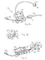
- FIG. 5 ais a perspective view of a preferred embodiment of a switch configuration and power contact device according to the present invention.
- FIG. 5 bis a perspective view of a further preferred embodiment of a switch configuration and power contact device according to the present invention.
- FIG. 6is a table of menu selections for operating a control mechanism according to the present invention.
- FIG. 7is a table of further menu selections for operating a control mechanism according to the present invention.
- FIG. 8is a perspective view of a device power cord device end security arrangement according to the present invention.
- FIG. 9 ais a top view of a device power cord device end security arrangement according to the present invention.
- FIG. 9 bis a side view of the device power cord device end security arrangement of FIG. 9 a.
- the present inventionis a method and apparatus for controlling usage time for devices, and the apparatus and system 10 is illustrated in FIGS. 1 5 .
- the apparatus 10includes a control mechanism 12 , which is in communication with multiple devices 14 or software programs, applications, processes or sub-processes resident on the device 14 .
- This control mechanism 12initiates action sequences that affect or change operational states of the devices 14 when certain parameters are met.
- these devices 14are electrically operated entertainment devices, such as television, gaming devices or consoles, personal computers, computer monitors, video cassette recorders, digital video devices, a software program resident on the device, an application resident on the device, a process of the device and a sub-process of the device.
- the term “device”includes all such devices, appliances, software programs and the like.
- the control mechanism 12is in communication with an input mechanism 16 .
- the input mechanism 16transmits user inputs to the control mechanism 12 .
- the input mechanism 16may include an alphanumeric keypad, a mouse, a touch-activated display device, a pen, a trackball, a touchpad, a lever, a joystick or other devices capable of accepting input from a user and transmitting this input to the control mechanism 12 .
- the control mechanism 12is also in communication with a visual display mechanism 18 . This visual display mechanism 18 allows a user to view certain selection menus, outputs and computational results and alphanumeric symbols, as produced or transmitted from the control mechanism 12 , as well as inputs, as transmitted from the input mechanism 16 .
- the control mechanism 12may be located in a dedicated housing 20 , together with the input mechanism 16 and the visual display mechanism 18 mounted thereon. However, it is also envisioned that the control mechanism 12 may exist as a program on a separate device, such as a television set, a personal computer, a hand-held computer, a computing device, etc. In such cases, these devices would typically have their own visual display mechanism 18 and input mechanism 16 .
- the housing 20is in the form of a hand-held, portable device, as illustrated in FIG. 2 .
- this hand-held deviceuses an alphanumeric keypad 22 as the input device 16 , and a screen 24 , located on the housing 20 , as the visual display mechanism 18 .
- the housing 20is sized such that the apparatus 10 is easily carried throughout one's dwelling.
- the apparatus 10includes a control mechanism 12 having a memory and a configurable database.
- This configurable databaseallows for the input, modification, deletion, and output of various variable and values, namely, multiple user accounts, device identification values unique to each of the devices 14 , and device usage allotment values for each device 14 corresponding to the device identification value for each user account.
- each user accountmay be assigned a specific user identification or group assignment, as well as a password or a pass code for each user in a particular group.
- the device identification valuemay be a label, which would name the device or application to be monitored, such as “TV”, “Personal Computer”, or “Internet Browser”.
- the control mechanism 12includes a user interface, which would allow the parent or guardian to set the settings for each user (child).
- the parent or guardianacts as the system administrator, having system privileges, and can therefore add or delete user accounts, add or delete device identification values for devices 14 , and add, modify or delete device usage allotment values for each device 14 and each user.
- control mechanismallows for user names, user types (restricted or unrestricted), weekday hours, weekend hours, password changing, bonus allowances (in the form of extra weekday or weekend hours), use restriction, user deletion, device selection, addition and deletion of device names and numbers, time or date selection and modification, time carryover options, language changing, day definitions and settings, hours per device, setup password changing, user statistics, device statistics, etc.
- the apparatus 10plugs into a typical wall outlet, either through a docking station or as a stand-alone, and communicates via X10, CEBus, RF Technology, bluetooth, and/or a computer networking protocol such as Ethernet or TCP/IP.
- Each switch 26is associated with and in direct communication with a device 14 . It is envisioned that any other viable communications technology may be used as well, such as the Internet, Ethernet, Infrared (IR), and hardwired connections. It is further envisioned that the Internet could permit guardians to check on children's usage when not at home.
- control mechanism 12may be a separate device, similar to a cell phone, it may also be an embedded microchip in an entertainment device, such as a television, a DVD player, a VCR, etc., in which the user interface would be accessible via an on-screen display on the television set connected to the entertainment device.
- entertainment devicesuch as a television, a DVD player, a VCR, etc.
- the control mechanism 12may include its own housing 20 , but as opposed to the screen 24 on the housing 20 , the visual display mechanism 18 may be a television screen, again using an on-screen display user interface.
- the control mechanism 12may be located as a program on a personal computer, where the logic and user interface would be present as software.
- FIG. 3 aOne preferred embodiment of an electronic communication switch configuration 26 is illustrated in FIG. 3 a .
- These switches 26are devices, which accept an electrical plug 27 of an entertainment device 14 , for example a television.
- this switch configuration 26includes a secure, tamper-proof enclosure 28 , as illustrated in FIGS. 3 a and 3 b.
- the switch configuration 26in a preferred embodiment, includes a hinged enclosure 28 adapted to house a power outlet 30 .
- This power outlet 30is configured to accept the electrical plug 27 of a device power cord 32 , which passes power to its respective device 14 .
- the power outlet 30 , the electrical plug 27 and the device power cord 32are all housed at least partially within the enclosure 28 , which is lockable by a removable locking mechanism 31 .
- the removable locking mechanism 31may be a typical lock that interacts with and is fed through projections 33 attached to the hinged enclosure 28 .
- the removable locking mechanism 31may require a key, pass code or other security feature to open the locking mechanism 31 from the enclosure 28 , thereby allowing entry therein.
- a microchip mechanism(not shown) is in communication with the power outlet 30 and is able to terminate power flow between the power outlet 30 and the device power cord 32 if instructed by the control mechanism 12 .
- the microchip mechanismis installed in a microchip housing 34 , and the microchip mechanism (not shown) is also in communication with an indicator light 36 . It is also envisioned that the microchip mechanism is installed within the locked enclosure 28 , and the indicator light 36 is attached directly to the enclosure 28 .
- the power outlet 30has a wall outlet connection that plugs into a standard wall outlet 44 .
- the microchip mechanismhas an embedded serial number, which the control mechanism 12 uses to identify the proper switch configuration 26 to which it should communicate an action sequence. While any number of action sequences is envisioned, typically the switch is a simple on/off switch, which would turn power to the device 14 on or off based on a command from the control mechanism 12 . Since the microchip mechanism may be programmed to accept signals via the electrical system of the house from the control mechanism 12 , the control mechanism 12 may then turn the entertainment device 14 on or off. It is also envisioned that the serialized or uniquely-identified microchip mechanism and power switch can be embedded into a standard size wall outlet, to be installed by an electrician in a user's wall.
- the enclosure 28may be sized and shaped so as to contain multiple power outlets 30 .
- Each of multiple device electrical plugs 27would be plugged into a respective power outlet 30 , and, each power outlet 30 would have an associated indicator light 36 and/or sound warning.
- each power outlet 30may also have a separate microchip housing 34 housing a microchip mechanism (not shown), or that the microchip mechanism would be placed within or associated with the enclosure 28 .
- the enclosure 28may also have one or multiple indicator lights 36 or sound warnings attached directly to the enclosure 28 , thereby allowing a user easy visual or audio indication of device 14 usage. It is further envisioned that an audio or sound-producing mechanism (not shown) could be used in conjunction with the indicator light 36 or alone.
- the control mechanism 12is able to communicate with the switch configuration 26 , and therefore with each device 14 , thereby controlling the device 14 .
- the indicator light 36 and/or the associated audio mechanismmay provide a visual signal or audio sequence indicating that the device 14 is in use or, in an alternative embodiment, may flash, beep or otherwise indicate that the user is using or nearing the allotted usage time for a device 14 .
- the apparatus 10may include some way for preventing or notifying the parent if a user attempts to disconnect the device power cord 32 from the power outlet 30 in order to obviate the apparatus 10 .
- the switch configuration of the apparatus 10may also include a power contact device 38 .
- This power contact device 38would provide some indication whether power is passing from the power outlet 30 to the device power cord 32 , and thus to the device 14 to be controlled. It is also envisioned that software could be used in connection with identifying any user attempts to gain access to “locked” software programs and applications.
- the power contact device 38includes a device housing 40 having one or more power contact device power outlets 42 positioned thereon.
- This power contact device power outlet 42is capable of accepting the electric plug 27 of the device power cord 32 and, therefore, pass power from the power contact device power outlet 42 to the device 14 .
- the power contact device 38is capable of being plugged into a typical and standard wall outlet 44 .
- the wall outlet 44can be any standard power outlet that is integrated with the floors, ceiling or walls of one's dwelling or other similar structure.
- the power contact device 38includes a load sensor (not shown) positioned within the device housing 40 and in communication with the power contact device power outlet 42 .
- This load sensormonitors whether power is passing from the power contact device power outlet 42 to the electric plug 27 and device power cord 32 , which powers the device 14 . If electrical contact is broken and the power load is interrupted, the load sensor produces a signal and initiates some action based upon this break in power. This may also be achieved when the power contact device 38 includes a mechanical switch (not shown), which actuates upon a physical break in contact between the electric plug 27 of the device power cord 32 and the power contact device power outlet 42 . As with the load sensor, a physical break in contact causes the mechanical switch to produce some mechanical or electrical signal and initiate an action sequence.
- the action sequencecan be visual or audio-based.
- the power contact device 38includes an indicator light 46 that visually indicates whether power is passing from the power contact device power outlet 42 to the electric plug 27 of the device power cord 32 .
- indicator light 46can provide another indication such as flashing, to reveal if power has been interrupted, which would occur if, for example, a child unplugs the power contact device 38 .
- the visual indicationcan be replaced or augmented by an audio mechanism (not shown) placed within the device housing 40 and having a speaker outlet 48 associated therewith. Similar to the indicator light 46 , the audio mechanism emits an audio sequence through the speaker outlet 48 , also indicating whether power is passing from the power contact device power outlet 42 to the device power cord 32 or if the power has been interrupted.
- the device power cord 32includes a device end 50 and an external power source end 52 .
- the external power source end 52is connectable to the power outlet 30 and/or the wall outlet 44 .
- the device end 50 of the device power cord 32is typically connectable to the device 14 that requires power, for example a personal computer, a VCR, etc.
- the apparatus 10further includes a length of indication tape 54 attached to the device end 50 of the device power cord 32 and also attached to a surface 56 , typically a rear surface, of the device 14 or a surface near the device 14 or the wall outlet, etc.
- indication tape 54Removal of the indication tape 54 leaves a conspicuous mark on the device surface 56 .
- Such indication tape 54is known in the industry, as many personal computer manufacturers put tamper-proof tape on personal computers to ensure that they are not opened. When the indication tape 54 is removed, there is a conspicuous mark left, and the indication tape 54 is not reusable.
- FIGS. 9 a and 9 bAnother security arrangement for ensuring the non-removal or indicating the non-removal of the device power cord 32 from the device 14 is illustrated in FIGS. 9 a and 9 b .
- the device end 50 of the device power cord 32has at least one and typically multiple tab elements 58 attached to and extending from the device end 50 . These tab elements 58 substantially abut the device surface 56 adjacent the device end 50 . It is to these tab elements 58 that the indication tape 54 is attached. While the length of indication tape 54 may be attached to only one tab element 58 , it is desirous to attach a length of indication tape 54 to each of the tab elements 58 in order to provide higher security precautions. As discussed above, when the indication tape 54 is removed, a conspicuous mark is left and the tape 54 cannot be reused. It is also envisioned that the indication tape 54 includes a unique serial number for further identification and security measures.
- the parent or guardiancreates a user account on a configurable database on the control mechanism 12 .
- the parentwould also input, via the input mechanism 16 , device identification values, which would be unique to each of the devices 14 , and thereby identify the device 14 to be controlled.
- the apparatus 10be capable of performing this identification by communicating with each active switch configuration 26 .
- FIG. 6illustrates a menu structure, which is accessible by each user when the control mechanism 12 is activated.
- the menu structure illustrated in FIG. 6is for a user.
- Another menu structureis illustrated in FIG. 7 .
- the menu structure in FIG. 7is a “setup” program, and is only accessible to a system administrator, typically a parent or guardian. While the menu structures of FIGS. 6 and 7 represent one preferred embodiment of menu control, many different functions, setups and alternative structures are envisioned.
- the parent or guardianmust next set up device usage allotment values for each device 14 to be controlled and for each user in the user database. After this information has been entered, a user can begin using the system. Specifically, the user inputs his or her user ID and password in order to access his or her “account”. The user then identifies the device 14 to be used, and begins using the device 14 if he or she has remaining time allotted.
- the control mechanism 12tracks the device usage value for the device 14 or software program corresponding to its device identification value. The control mechanism 12 continues to monitor the device usage value for the user as he or she uses the device 14 corresponding to the device identification value. Next, the control mechanism 12 initiates an action sequence, based upon the device usage value. Any manner of determining whether the device usage equals or exceeds the device allotment is envisioned. For example, the control mechanism 16 may accrue time and compare it to the allotted time amount or may start with the allotted time and “count down” to zero.
- the apparatus 10may also have a warning value, such that when the device usage value equals the warning value, the action sequence is a warning sequence, which somehow indicates to the user that he or she is approaching termination of their usage of the device 14 .
- the indicator light 36 on the microchip housing 34may be used to indicate this warning.
- a sound alarm or other visual indicatorcould also be projected or initiated.
- the control mechanism 12instructs the switch configuration 26 to terminate power at the power outlet 30 , thereby terminating power to the entertainment device 14 . In this manner, when the device usage allotment value set by the parent or guardian is met, the user or child can no longer use that device 14 , without gaining additional device usage allotment.
- Parents or guardiansmay, for each child and each entertainment device 14 or software application on the device 14 in the household, allot a certain amount of hours per week and a certain amount of hours per weekend for each child and either each device 14 or all devices 14 .
- the child wants to use the device 14they simply enter their user ID and/or password into the control mechanism 12 via the input mechanism 16 , and the apparatus 10 allows access by allowing power to flow to that device 14 .
- the childWhen the child is finished using the entertainment device 14 , he or she simply logs off from that device 14 via the user interface on the control mechanism 12 .
- the indicator light 36lights up or an audio sequence is initiated, for example, three minutes before the time limit is reached.
- the unit or device 14is shut off by the control mechanism 12 , and the child or user is then locked out of the entertainment device 14 or devices 14 until a new time cycle begins, for example, the start of a new day, week or weekend.
- certain applicationsfor example, a software program, such as a video game, an Internet Browser, etc.
- the application budget timeaccess to the application is restricted, as opposed to power termination to the device 14 . Therefore, any device 14 and/or a software program resident on the device, an application resident on the device, a process of the device and a sub-process of the device may have multiple device usage allotment values, depending upon the day, date, hour or other variable.
- the apparatus 10allows the parent or guardian to manage time budgets in a flexible manner.
- a common time budget management techniquewould be to allot a certain number of hours for a five-day weekday, and a certain amount of hours for the two-day weekend. These allowable hours may be used on any device 14 .
- time budgetsmay also be set up on a per device 14 basis, for example, each child may have a certain number of hours per week or per day on the television and a certain number of hours per week or per day on the video game console. Further time budgets may also be set per day instead of per weekend or weekday period, and may be easily modified in the event that the child has extra days off school, such as for Christmas vacation, etc.
- parent or guardianmay add additional hours (as a bonus) or take away hours or time (as a punishment) from any weekday, weekend or day period.
- parentsmay set criteria or some predetermined mathematical formula, which would give the children an incentive to spend less time on entertainment devices 14 . For example, in a week that children do not use all of their hours, parents may choose to add half (or any percentage) of the number of unused hours in any given weekend to the following week or the upcoming weekend. So, for example, if a child is allotted ten hours in a five-day weekday period, and by Friday night the child only used seven of his allotted ten hours, the following week the child will have 11.5 (10 hours+1.5 hours) of time.
- the user interface on the control mechanism 12may also have a switch to shut off all of the entertainment devices 14 , such that all users may be restricted at one time. For example, an angry parent may want to turn off all entertainment devices 14 for one night for all restricted users at one time.
- the parentmay also wish to set up a schedule, where all entertainment devices 14 are shut off automatically between certain hours. For example, a parent may want all entertainment devices 14 shut off during dinner hours. In this case, the parent may program the control mechanism 12 to shut off all devices 14 between the hours of 5:00 p.m. and 7:30 p.m. This functionality allows the parent to terminate power to or otherwise affect the state of one or more of the devices 14 on a periodic, predetermined or set basis.
- the control mechanism 12also allows the parent to monitor statistics on which of their children are using which of the household entertainment devices 14 at what time. For example, a parent can select a child in the user interface of the control mechanism 12 and see the last 50 uses of each entertainment device 14 in the house, showing details of each use including device name, amount of time used, and date and time of use. The parent may also see statistics on each entertainment device 14 in the house, including the past 50 users of that device 14 and the date, time, and amount of time used for each use.
- the control mechanism 12may allow or require that no device 14 be used by a restricted user between certain hours. For example, parents may decide to disallow use of any device between the hours of 9:00 p.m. and 7:00 a.m. on weekdays. However, since the parent or guardian is the system administrator, they would be considered “unrestricted” users of the apparatus 10 and system. Any time a parent or guardian wishes to use one of the household entertainment devices 14 or other appliances connected to the system, the parent simply types in a system password, which would yield unrestricted use of any device 14 . It is also envisioned that the control mechanism 12 and user interface would have a setting to change a language for the user interface.
- the present inventionis a method and apparatus 10 for remotely controlling multiple devices 14 and/or software programs and budgeting time for using the device 14 for each user.
- the present inventionallows a parent or guardian to limit entertainment device 14 usage time for their children, and also allows for the remote control of multiple devices 14 and the power to these multiple electronic devices 14 .
- the present inventionallows parents to administer “time budgets” to their children, thereby ensuring that the children spend less time on entertainment devices 14 , via either limited time on entertainment devices 14 or carefully plan their limited time on entertainment devices 14 and spend more time on more viable activities.
- This inventionwill also allow parents to better manage the discipline of their children, by giving them hard data with which to discuss the problem of excessive use of entertainment devices 14 .
Landscapes
- Engineering & Computer Science (AREA)
- Computer Networks & Wireless Communication (AREA)
- Physics & Mathematics (AREA)
- General Physics & Mathematics (AREA)
- Selective Calling Equipment (AREA)
Abstract
Description
Claims (23)
Priority Applications (1)
| Application Number | Priority Date | Filing Date | Title |
|---|---|---|---|
| US12/575,395US8077016B2 (en) | 2002-05-28 | 2009-10-07 | Method and apparatus for remotely controlling a plurality of devices |
Applications Claiming Priority (5)
| Application Number | Priority Date | Filing Date | Title |
|---|---|---|---|
| US38387502P | 2002-05-28 | 2002-05-28 | |
| US10/388,330US7098772B2 (en) | 2002-05-28 | 2003-03-13 | Method and apparatus for remotely controlling a plurality of devices |
| US11/473,395US7362213B2 (en) | 2002-05-28 | 2006-06-23 | Method and apparatus for remotely controlling a plurality of devices |
| US12/049,988US7619504B2 (en) | 2002-05-28 | 2008-03-17 | Method and apparatus for remotely controlling a plurality of devices |
| US12/575,395US8077016B2 (en) | 2002-05-28 | 2009-10-07 | Method and apparatus for remotely controlling a plurality of devices |
Related Parent Applications (1)
| Application Number | Title | Priority Date | Filing Date |
|---|---|---|---|
| US12/049,988ContinuationUS7619504B2 (en) | 2002-05-28 | 2008-03-17 | Method and apparatus for remotely controlling a plurality of devices |
Publications (2)
| Publication Number | Publication Date |
|---|---|
| US20100026471A1 US20100026471A1 (en) | 2010-02-04 |
| US8077016B2true US8077016B2 (en) | 2011-12-13 |
Family
ID=29587044
Family Applications (4)
| Application Number | Title | Priority Date | Filing Date |
|---|---|---|---|
| US10/388,330Expired - LifetimeUS7098772B2 (en) | 2002-05-28 | 2003-03-13 | Method and apparatus for remotely controlling a plurality of devices |
| US11/473,395Active2026-07-10US7362213B2 (en) | 2002-05-28 | 2006-06-23 | Method and apparatus for remotely controlling a plurality of devices |
| US12/049,988Expired - LifetimeUS7619504B2 (en) | 2002-05-28 | 2008-03-17 | Method and apparatus for remotely controlling a plurality of devices |
| US12/575,395Expired - Fee RelatedUS8077016B2 (en) | 2002-05-28 | 2009-10-07 | Method and apparatus for remotely controlling a plurality of devices |
Family Applications Before (3)
| Application Number | Title | Priority Date | Filing Date |
|---|---|---|---|
| US10/388,330Expired - LifetimeUS7098772B2 (en) | 2002-05-28 | 2003-03-13 | Method and apparatus for remotely controlling a plurality of devices |
| US11/473,395Active2026-07-10US7362213B2 (en) | 2002-05-28 | 2006-06-23 | Method and apparatus for remotely controlling a plurality of devices |
| US12/049,988Expired - LifetimeUS7619504B2 (en) | 2002-05-28 | 2008-03-17 | Method and apparatus for remotely controlling a plurality of devices |
Country Status (3)
| Country | Link |
|---|---|
| US (4) | US7098772B2 (en) |
| AU (1) | AU2003239912A1 (en) |
| WO (1) | WO2003100994A2 (en) |
Cited By (4)
| Publication number | Priority date | Publication date | Assignee | Title |
|---|---|---|---|---|
| US20100231432A1 (en)* | 2009-03-13 | 2010-09-16 | Hiroyuki Shigei | Remote controller and remote control system |
| US20120232714A1 (en)* | 2011-03-08 | 2012-09-13 | Ricket Douglas J | Systems and Methods for Activation and Deactivation of Appliances |
| US9942336B2 (en) | 2015-05-05 | 2018-04-10 | International Business Machines Corporation | Time and task based validation to enable or disable parental controls |
| US20180137694A1 (en)* | 2015-03-31 | 2018-05-17 | SZ DJI Technology Co., Ltd. | Systems and methods for monitoring flight |
Families Citing this family (57)
| Publication number | Priority date | Publication date | Assignee | Title |
|---|---|---|---|---|
| US7098772B2 (en)* | 2002-05-28 | 2006-08-29 | Cohen Richard S | Method and apparatus for remotely controlling a plurality of devices |
| US20040003393A1 (en)* | 2002-06-26 | 2004-01-01 | Koninlkijke Philips Electronics N.V. | Method, system and apparatus for monitoring use of electronic devices by user detection |
| US7142814B2 (en)* | 2002-12-11 | 2006-11-28 | Shary Nassimi | Automatic Bluetooth inquiry mode headset |
| US7233916B2 (en)* | 2004-06-15 | 2007-06-19 | Motorola, Inc. | Method and system for tracking content rental |
| KR100608594B1 (en)* | 2004-07-01 | 2006-08-03 | 삼성전자주식회사 | Payment information notification method in a broadcast receiver and the broadcast receiver |
| US8819140B2 (en) | 2004-07-09 | 2014-08-26 | Qualcomm Incorporated | System and method for enabling the establishment and use of a personal network |
| US8738693B2 (en) | 2004-07-09 | 2014-05-27 | Qualcomm Incorporated | System and method for managing distribution of media files |
| US8787164B2 (en) | 2004-07-09 | 2014-07-22 | Qualcomm Incorporated | Media delivery system and method for transporting media to desired target devices |
| US9077766B2 (en) | 2004-07-09 | 2015-07-07 | Qualcomm Incorporated | System and method for combining memory resources for use on a personal network |
| US8195744B2 (en) | 2004-07-09 | 2012-06-05 | Orb Networks, Inc. | File sharing system for use with a network |
| US7937484B2 (en) | 2004-07-09 | 2011-05-03 | Orb Networks, Inc. | System and method for remotely controlling network resources |
| US20060026279A1 (en)* | 2004-07-28 | 2006-02-02 | Microsoft Corporation | Strategies for monitoring the consumption of resources |
| US7154380B1 (en) | 2004-11-24 | 2006-12-26 | Tarrab Jr George | Power distribution and timing device |
| US20060156327A1 (en)* | 2005-01-11 | 2006-07-13 | Dolph Blaine H | Method for tracking time spent interacting with different remote controlled media devices |
| US20100180324A1 (en)* | 2005-02-24 | 2010-07-15 | Rangan Karur | Method for protecting passwords using patterns |
| KR100724939B1 (en) | 2005-06-20 | 2007-06-04 | 삼성전자주식회사 | Implementation method of user interface using camera and mobile communication terminal for same |
| US20070143479A1 (en)* | 2005-12-16 | 2007-06-21 | Putnam Michael A | Systems and methods for centralized custodial control |
| JP4872431B2 (en)* | 2006-04-17 | 2012-02-08 | 船井電機株式会社 | Electronic equipment control system |
| KR100725544B1 (en)* | 2006-05-01 | 2007-06-08 | 삼성전자주식회사 | A mobile communication terminal and a method for blocking harmful information thereof |
| US20070258590A1 (en)* | 2006-05-02 | 2007-11-08 | Alcatel | Method and system for triple play service control |
| KR100763528B1 (en)* | 2006-07-07 | 2007-10-04 | 한국전자통신연구원 | Timer control system via network |
| US8973072B2 (en) | 2006-10-19 | 2015-03-03 | Qualcomm Connected Experiences, Inc. | System and method for programmatic link generation with media delivery |
| US8027518B2 (en)* | 2007-06-25 | 2011-09-27 | Microsoft Corporation | Automatic configuration of devices based on biometric data |
| US20080320126A1 (en)* | 2007-06-25 | 2008-12-25 | Microsoft Corporation | Environment sensing for interactive entertainment |
| US20080319827A1 (en)* | 2007-06-25 | 2008-12-25 | Microsoft Corporation | Mining implicit behavior |
| US8495670B2 (en)* | 2007-09-21 | 2013-07-23 | Echostar Technologies L.L.C. | Accounting for viewing and recording of programs |
| US20090102616A1 (en)* | 2007-10-22 | 2009-04-23 | Microsoft Corporation | Time-based access control for an entertainment console |
| US20130227653A1 (en)* | 2008-11-29 | 2013-08-29 | Yu Yung Choi | System and method for streamlined registration of products over a communication network and for verification and management of information related thereto |
| KR101311669B1 (en)* | 2007-12-17 | 2013-09-27 | 노키아 코포레이션 | Accessory configuration and management |
| US8185127B1 (en)* | 2008-02-12 | 2012-05-22 | Sprint Communications Company L. P. | Method and system for allocating network resources for a single user operating multiple devices |
| US20090232472A1 (en)* | 2008-03-11 | 2009-09-17 | Echostar Technologies L.L.C. | Methods and apparatus for providing usage timers for a presentation device |
| US9078043B2 (en)* | 2008-08-01 | 2015-07-07 | Verizon Patent And Licensing Inc. | Media source monitoring and parental awards |
| US20100095319A1 (en)* | 2008-10-15 | 2010-04-15 | Samsung Electronics Co., Ltd. | System and method for monitoring television viewing using keyframes |
| US9237295B2 (en)* | 2008-10-15 | 2016-01-12 | Samsung Electronics Co., Ltd. | System and method for keyframe analysis and distribution from broadcast television |
| US20100095345A1 (en)* | 2008-10-15 | 2010-04-15 | Samsung Electronics Co., Ltd. | System and method for acquiring and distributing keyframe timelines |
| DE102008064119B4 (en)* | 2008-12-19 | 2014-11-20 | Airbus Operations Gmbh | Galley for a plane |
| TWI379592B (en)* | 2008-12-31 | 2012-12-11 | Mediatek Inc | Display systems and methods |
| US8917181B2 (en)* | 2010-05-07 | 2014-12-23 | Mikael Edlund | Method for monitoring an individual |
| GB201008368D0 (en) | 2010-05-20 | 2010-07-07 | Moore Jesse K | Mobile meter |
| US8514085B2 (en) | 2010-06-17 | 2013-08-20 | International Business Machines Corporation | Intelligent switching method and apparatus |
| CN102609037A (en)* | 2011-01-25 | 2012-07-25 | 鸿富锦精密工业(深圳)有限公司 | Computer host |
| US8863202B2 (en)* | 2011-11-11 | 2014-10-14 | Sony Corporation | System and method for voice driven cross service search using second display |
| US8489481B2 (en) | 2011-11-21 | 2013-07-16 | M-Kopa Ipr, Llc | Transaction processing and remote activation |
| US10600044B2 (en)* | 2011-12-20 | 2020-03-24 | Angaza Design, Inc. | Solar lighting with pay-as-you go technology |
| US9037283B2 (en) | 2012-01-05 | 2015-05-19 | International Business Machines Corporation | Apparatus safeguard |
| US8972753B2 (en)* | 2012-02-14 | 2015-03-03 | International Business Machines Corporation | Determining suitability for disconnection from power outlet of a power distribution unit based on status of power supplies of a hardware device |
| US20140156281A1 (en)* | 2012-12-03 | 2014-06-05 | Qualcomm Incorporated | Voice-controlled configuration of an automation system |
| US20150095985A1 (en)* | 2013-09-27 | 2015-04-02 | Alcatel-Lucent Usa Inc. | Parental Control System For Controlling Access To Online Store Contents |
| US9148698B1 (en) | 2013-11-14 | 2015-09-29 | Google Inc. | Methods, systems, and media for controlling a presentation of media content |
| WO2015153124A1 (en) | 2014-04-02 | 2015-10-08 | Angaza Design, Inc. | Solar lighting with pay-as-you-go technology |
| US9787856B2 (en)* | 2014-12-29 | 2017-10-10 | Tracfone Wireless, Inc. | Hybrid network based metering server for a shared service and tracking client for wireless services |
| US9769642B2 (en) | 2015-02-20 | 2017-09-19 | Tracfone Wireless, Inc. | Method and system for family plan sharing of wireless services |
| US10366556B1 (en)* | 2018-08-07 | 2019-07-30 | LockState, Inc. | Intelligent lock |
| US20200067245A1 (en)* | 2018-08-24 | 2020-02-27 | Matthew Stearns Maley | Lockable power outlet control plug and system and method of using same to connect and disconnect power to an electrical device |
| US11720155B2 (en)* | 2018-11-16 | 2023-08-08 | Kito Bradford | System and method of regulating usage of an electronic device |
| CN110557655B (en)* | 2019-09-06 | 2021-10-26 | 卓米私人有限公司 | Video picture display method and device, electronic equipment and storage medium |
| CN112565823A (en)* | 2020-12-09 | 2021-03-26 | 深圳市朗强科技有限公司 | Method and equipment for sending and receiving high-definition video data |
Citations (38)
| Publication number | Priority date | Publication date | Assignee | Title |
|---|---|---|---|---|
| US3983553A (en) | 1975-05-12 | 1976-09-28 | General Motors Corporation | Appliance remote touch-control panel with sound system |
| US4306293A (en) | 1979-08-30 | 1981-12-15 | Marathe Sharad M | Energy monitoring system |
| US4418333A (en) | 1981-06-08 | 1983-11-29 | Pittway Corporation | Appliance control system |
| US4510778A (en) | 1983-12-27 | 1985-04-16 | The Maytag Company | Control system for a combined appliance |
| US4703306A (en) | 1986-09-26 | 1987-10-27 | The Maytag Company | Appliance system |
| US5046157A (en)* | 1988-02-03 | 1991-09-03 | Smith Stephen W | Time control device for appliances |
| US5051837A (en)* | 1990-06-06 | 1991-09-24 | Mcjunkin Thomas N | Home entertainment equipment control apparatus |
| US5083122A (en) | 1989-02-21 | 1992-01-21 | Osi Security Devices | Programmable individualized security system for door locks |
| US5203848A (en) | 1992-01-16 | 1993-04-20 | Myson Technology, Inc. | Television game console and electronic control device for controlling the allowable playing time of the television game console |
| US5231661A (en)* | 1991-07-31 | 1993-07-27 | Gold Medal Kids, Inc. | Television viewing control device and method |
| US5267734A (en) | 1990-05-31 | 1993-12-07 | Rare Coin It, Inc. | Video game having calendar dependent functionality |
| US5331353A (en)* | 1992-03-10 | 1994-07-19 | Mindmaster Inc. | Device for limiting the amount of time an electrical appliance such as a television may be used |
| US5377269A (en) | 1992-10-29 | 1994-12-27 | Intelligent Security Systems, Inc. | Security access and monitoring system for personal computer |
| US5410326A (en) | 1992-12-04 | 1995-04-25 | Goldstein; Steven W. | Programmable remote control device for interacting with a plurality of remotely controlled devices |
| US5465113A (en) | 1993-12-13 | 1995-11-07 | At&T Corp. | Programmable channel regulating cable television controller |
| US5548345A (en) | 1995-01-05 | 1996-08-20 | Protelcon, Inc. | Video viewing censoring supervision system |
| US5586174A (en) | 1990-08-15 | 1996-12-17 | Advanced Laundry Devices, Inc. | Condition responsive indicating system for interactively indicating status of a plurality of electrical appliances |
| US5608389A (en) | 1993-12-20 | 1997-03-04 | Casio Computer Co., Ltd. | Remote control devices for electronic appliances |
| US5715020A (en) | 1993-08-13 | 1998-02-03 | Kabushiki Kaisha Toshiba | Remote control system in which a plurality of remote control units are managed by a single remote control device |
| US5917256A (en) | 1997-02-04 | 1999-06-29 | Broadbent, Ii; Frederick J. | Timing device for blocking television signals |
| US5964661A (en)* | 1995-11-24 | 1999-10-12 | Dodge; Samuel D. | Apparatus and method for timing video games |
| US6005476A (en) | 1998-07-24 | 1999-12-21 | Valiulis; Carl | Electronic identification, control, and security system for consumer electronics and the like |
| US6016407A (en) | 1997-07-17 | 2000-01-18 | Nikon Corporation | Energy saving electronic device |
| US6097306A (en) | 1996-12-03 | 2000-08-01 | E.J. Brooks Company | Programmable lock and security system therefor |
| US6112127A (en) | 1996-11-06 | 2000-08-29 | Ameritech Services, Inc. | Method and system of programming at least one appliance to change state upon the occurrence of a trigger event |
| US6161133A (en) | 1998-10-19 | 2000-12-12 | Lexton Systems, Inc. | Method and apparatus for configuration of an internet appliance |
| US6198408B1 (en) | 1994-11-29 | 2001-03-06 | Elihay Cohen | Method and apparatus for controlling electrical appliances by remote control transmitters |
| US6208042B1 (en) | 1999-04-05 | 2001-03-27 | Gilbert Solis | Anti-reactivation safety device |
| US6256378B1 (en) | 1999-01-22 | 2001-07-03 | Pointset Corporation | Method and apparatus for setting programmable features of an appliance |
| US6292718B2 (en) | 1999-01-28 | 2001-09-18 | International Business Machines Corp. | Electronic control system |
| WO2003100994A2 (en) | 2002-05-28 | 2003-12-04 | Cohen Richard S | Method and apparatus for remotely controlling a plurality of devices |
| US6678824B1 (en) | 1999-11-02 | 2004-01-13 | Agere Systems Inc. | Application usage time limiter |
| US6781923B1 (en) | 2000-09-13 | 2004-08-24 | Timex Group B.V. | Method and apparatus for tracking usage of a multi-functional electronic device |
| US6917853B2 (en) | 2000-05-23 | 2005-07-12 | Munroe Chirnomas | Method and apparatus for controlling rented or leased or loaned equipment |
| US6934625B2 (en) | 2002-03-13 | 2005-08-23 | Hewlett-Packard Development Company, L.P. | Tracking system and method |
| US7047452B2 (en)* | 2001-12-11 | 2006-05-16 | International Business Machines Corporation | Method and system for detecting excessive use of a data processing system |
| US7048452B2 (en) | 2003-11-10 | 2006-05-23 | Jds Uniphase Corporation | Transceiver guide rail with heat sink guide |
| US20090089826A1 (en)* | 2007-09-28 | 2009-04-02 | Echostar Technologies Corporation | Systems and methods for managing parental control information in multiple entertainment devices |
Family Cites Families (1)
| Publication number | Priority date | Publication date | Assignee | Title |
|---|---|---|---|---|
| US441833A (en)* | 1890-12-02 | Watch-case spring |
- 2003
- 2003-03-13USUS10/388,330patent/US7098772B2/ennot_activeExpired - Lifetime
- 2003-05-28WOPCT/US2003/016727patent/WO2003100994A2/ennot_activeApplication Discontinuation
- 2003-05-28AUAU2003239912Apatent/AU2003239912A1/ennot_activeAbandoned
- 2006
- 2006-06-23USUS11/473,395patent/US7362213B2/enactiveActive
- 2008
- 2008-03-17USUS12/049,988patent/US7619504B2/ennot_activeExpired - Lifetime
- 2009
- 2009-10-07USUS12/575,395patent/US8077016B2/ennot_activeExpired - Fee Related
Patent Citations (41)
| Publication number | Priority date | Publication date | Assignee | Title |
|---|---|---|---|---|
| US3983553A (en) | 1975-05-12 | 1976-09-28 | General Motors Corporation | Appliance remote touch-control panel with sound system |
| US4306293A (en) | 1979-08-30 | 1981-12-15 | Marathe Sharad M | Energy monitoring system |
| US4418333A (en) | 1981-06-08 | 1983-11-29 | Pittway Corporation | Appliance control system |
| US4510778A (en) | 1983-12-27 | 1985-04-16 | The Maytag Company | Control system for a combined appliance |
| US4703306A (en) | 1986-09-26 | 1987-10-27 | The Maytag Company | Appliance system |
| US5046157A (en)* | 1988-02-03 | 1991-09-03 | Smith Stephen W | Time control device for appliances |
| US5083122A (en) | 1989-02-21 | 1992-01-21 | Osi Security Devices | Programmable individualized security system for door locks |
| US5267734C1 (en) | 1990-05-31 | 2001-07-17 | Rare Coin It Inc | Video game having calendar dependent functionality |
| US5267734A (en) | 1990-05-31 | 1993-12-07 | Rare Coin It, Inc. | Video game having calendar dependent functionality |
| US5051837A (en)* | 1990-06-06 | 1991-09-24 | Mcjunkin Thomas N | Home entertainment equipment control apparatus |
| US5586174A (en) | 1990-08-15 | 1996-12-17 | Advanced Laundry Devices, Inc. | Condition responsive indicating system for interactively indicating status of a plurality of electrical appliances |
| US5231661A (en)* | 1991-07-31 | 1993-07-27 | Gold Medal Kids, Inc. | Television viewing control device and method |
| US5203848A (en) | 1992-01-16 | 1993-04-20 | Myson Technology, Inc. | Television game console and electronic control device for controlling the allowable playing time of the television game console |
| US5331353A (en)* | 1992-03-10 | 1994-07-19 | Mindmaster Inc. | Device for limiting the amount of time an electrical appliance such as a television may be used |
| US5377269A (en) | 1992-10-29 | 1994-12-27 | Intelligent Security Systems, Inc. | Security access and monitoring system for personal computer |
| US5410326A (en) | 1992-12-04 | 1995-04-25 | Goldstein; Steven W. | Programmable remote control device for interacting with a plurality of remotely controlled devices |
| US5715020A (en) | 1993-08-13 | 1998-02-03 | Kabushiki Kaisha Toshiba | Remote control system in which a plurality of remote control units are managed by a single remote control device |
| US5465113A (en) | 1993-12-13 | 1995-11-07 | At&T Corp. | Programmable channel regulating cable television controller |
| US5608389A (en) | 1993-12-20 | 1997-03-04 | Casio Computer Co., Ltd. | Remote control devices for electronic appliances |
| US6198408B1 (en) | 1994-11-29 | 2001-03-06 | Elihay Cohen | Method and apparatus for controlling electrical appliances by remote control transmitters |
| US5548345A (en) | 1995-01-05 | 1996-08-20 | Protelcon, Inc. | Video viewing censoring supervision system |
| US6025869A (en) | 1995-01-05 | 2000-02-15 | Music Corporation | Video viewing supervision system |
| US5964661A (en)* | 1995-11-24 | 1999-10-12 | Dodge; Samuel D. | Apparatus and method for timing video games |
| US6112127A (en) | 1996-11-06 | 2000-08-29 | Ameritech Services, Inc. | Method and system of programming at least one appliance to change state upon the occurrence of a trigger event |
| US6097306A (en) | 1996-12-03 | 2000-08-01 | E.J. Brooks Company | Programmable lock and security system therefor |
| US5917256A (en) | 1997-02-04 | 1999-06-29 | Broadbent, Ii; Frederick J. | Timing device for blocking television signals |
| US6016407A (en) | 1997-07-17 | 2000-01-18 | Nikon Corporation | Energy saving electronic device |
| US6005476A (en) | 1998-07-24 | 1999-12-21 | Valiulis; Carl | Electronic identification, control, and security system for consumer electronics and the like |
| US6161133A (en) | 1998-10-19 | 2000-12-12 | Lexton Systems, Inc. | Method and apparatus for configuration of an internet appliance |
| US6256378B1 (en) | 1999-01-22 | 2001-07-03 | Pointset Corporation | Method and apparatus for setting programmable features of an appliance |
| US6292718B2 (en) | 1999-01-28 | 2001-09-18 | International Business Machines Corp. | Electronic control system |
| US6208042B1 (en) | 1999-04-05 | 2001-03-27 | Gilbert Solis | Anti-reactivation safety device |
| US6678824B1 (en) | 1999-11-02 | 2004-01-13 | Agere Systems Inc. | Application usage time limiter |
| US6917853B2 (en) | 2000-05-23 | 2005-07-12 | Munroe Chirnomas | Method and apparatus for controlling rented or leased or loaned equipment |
| US6781923B1 (en) | 2000-09-13 | 2004-08-24 | Timex Group B.V. | Method and apparatus for tracking usage of a multi-functional electronic device |
| US7047452B2 (en)* | 2001-12-11 | 2006-05-16 | International Business Machines Corporation | Method and system for detecting excessive use of a data processing system |
| US6934625B2 (en) | 2002-03-13 | 2005-08-23 | Hewlett-Packard Development Company, L.P. | Tracking system and method |
| WO2003100994A2 (en) | 2002-05-28 | 2003-12-04 | Cohen Richard S | Method and apparatus for remotely controlling a plurality of devices |
| US7098772B2 (en) | 2002-05-28 | 2006-08-29 | Cohen Richard S | Method and apparatus for remotely controlling a plurality of devices |
| US7048452B2 (en) | 2003-11-10 | 2006-05-23 | Jds Uniphase Corporation | Transceiver guide rail with heat sink guide |
| US20090089826A1 (en)* | 2007-09-28 | 2009-04-02 | Echostar Technologies Corporation | Systems and methods for managing parental control information in multiple entertainment devices |
Non-Patent Citations (2)
| Title |
|---|
| Stolowitz Ford Cowger LLP; Related Case Listing; Feb. 11, 2011; 1 Page. |
| United States Patent and Trademark Office, PCT; International Search Report; PCT/US03/16727; Jun. 4, 2004; 3 Pages. |
Cited By (13)
| Publication number | Priority date | Publication date | Assignee | Title |
|---|---|---|---|---|
| US8390503B2 (en)* | 2009-03-13 | 2013-03-05 | Sony Corporation | Remote controller and remote control system |
| US20100231432A1 (en)* | 2009-03-13 | 2010-09-16 | Hiroyuki Shigei | Remote controller and remote control system |
| US9020852B2 (en)* | 2011-03-08 | 2015-04-28 | D.Light Design, Inc. | Systems and methods for activation and deactivation of appliances |
| US8355805B2 (en)* | 2011-03-08 | 2013-01-15 | D. Light Design, Inc. | Systems and methods for activation and deactivation of appliances |
| US20130211551A1 (en)* | 2011-03-08 | 2013-08-15 | Douglas J. Ricket | Systems and Methods For Activation and Deactivation of Appliances |
| US20140172122A1 (en)* | 2011-03-08 | 2014-06-19 | D.Light Design, Inc. | Systems and methods for activation and deactivation of appliances |
| US20120232714A1 (en)* | 2011-03-08 | 2012-09-13 | Ricket Douglas J | Systems and Methods for Activation and Deactivation of Appliances |
| US9052702B2 (en)* | 2011-03-08 | 2015-06-09 | D. Light Design, Inc. | Systems and methods for activation and deactivation of appliances |
| US20160041591A1 (en)* | 2011-03-08 | 2016-02-11 | D.Light Design, Inc. | Systems and methods for activation and deactivation of appliances |
| US9799018B2 (en)* | 2011-03-08 | 2017-10-24 | D.Light Design, Inc. | Systems and methods for activation and deactivation of appliances |
| US20180137694A1 (en)* | 2015-03-31 | 2018-05-17 | SZ DJI Technology Co., Ltd. | Systems and methods for monitoring flight |
| US10692311B2 (en)* | 2015-03-31 | 2020-06-23 | SZ DJI Technology Co., Ltd. | Systems and methods for monitoring flight |
| US9942336B2 (en) | 2015-05-05 | 2018-04-10 | International Business Machines Corporation | Time and task based validation to enable or disable parental controls |
Also Published As
| Publication number | Publication date |
|---|---|
| US20060238313A1 (en) | 2006-10-26 |
| US20080157937A1 (en) | 2008-07-03 |
| WO2003100994A3 (en) | 2004-07-29 |
| AU2003239912A8 (en) | 2003-12-12 |
| WO2003100994A2 (en) | 2003-12-04 |
| AU2003239912A1 (en) | 2003-12-12 |
| US20100026471A1 (en) | 2010-02-04 |
| US7098772B2 (en) | 2006-08-29 |
| US20040060059A1 (en) | 2004-03-25 |
| US7362213B2 (en) | 2008-04-22 |
| US7619504B2 (en) | 2009-11-17 |
Similar Documents
| Publication | Publication Date | Title |
|---|---|---|
| US8077016B2 (en) | Method and apparatus for remotely controlling a plurality of devices | |
| US5051837A (en) | Home entertainment equipment control apparatus | |
| US8289132B2 (en) | Locking system for electronic equipment | |
| KR100287038B1 (en) | Method and apparatus for wireless remote control of electronic device based on software | |
| US8963681B2 (en) | Operating control system for electronic equipment | |
| US20060041655A1 (en) | Bi-directional remote control for remotely controllable apparatus | |
| US20070074284A1 (en) | Personal computer access control lockout | |
| US10279268B2 (en) | Extensible video game time limiter | |
| US20210287197A1 (en) | Configurable correctional facility computer kiosk systems and methods for portable electronic device access and management | |
| US20120250831A1 (en) | Communication Signal Distribution Unit And Methods | |
| JP2020526176A (en) | Electrical safety cover | |
| KR101617149B1 (en) | Power Controller for Limit of Time to Use Electronic Devices | |
| US20100193337A1 (en) | Systems and methods for controlling operation of electronic devices | |
| US20220300664A1 (en) | Device, software, and methods for administrative control of electronic devices | |
| US20030189591A1 (en) | Terminal for controlling use of a computer | |
| US20040252247A1 (en) | System for management of decoding devices and method for management of decoding devices | |
| US7406521B2 (en) | System and methods for controlled device access | |
| JP2021129174A (en) | Control system, control method, and program | |
| JP2007251349A (en) | Electronic equipment system | |
| WO2007075530A2 (en) | Systems and methods for centralized custodial control | |
| US20040051393A1 (en) | Electrical power control system | |
| US20040075775A1 (en) | Device for limiting time of use of electronic equipment | |
| US20060238035A1 (en) | Electricity supply control system | |
| CA2286370A1 (en) | Electrical device locked timer control | |
| GB2394343A (en) | Electricity supply control device |
Legal Events
| Date | Code | Title | Description |
|---|---|---|---|
| AS | Assignment | Owner name:DORRANCE IP, LP,PENNSYLVANIA Free format text:ASSIGNMENT OF ASSIGNORS INTEREST;ASSIGNOR:COHEN, RICHARD S.;REEL/FRAME:023875/0041 Effective date:20100126 Owner name:DORRANCE IP, LP, PENNSYLVANIA Free format text:ASSIGNMENT OF ASSIGNORS INTEREST;ASSIGNOR:COHEN, RICHARD S.;REEL/FRAME:023875/0041 Effective date:20100126 | |
| AS | Assignment | Owner name:DORRANCE IP, LP, PENNSYLVANIA Free format text:CONFIRMATORY ASSIGNMENT;ASSIGNOR:COHEN, RICHARD S.;REEL/FRAME:025526/0464 Effective date:20101202 | |
| AS | Assignment | Owner name:SCHEIDNER RESEARCH LLC, DELAWARE Free format text:ASSIGNMENT OF ASSIGNORS INTEREST;ASSIGNOR:DORRANCE IP, LP;REEL/FRAME:025738/0898 Effective date:20101028 | |
| ZAAA | Notice of allowance and fees due | Free format text:ORIGINAL CODE: NOA | |
| ZAAB | Notice of allowance mailed | Free format text:ORIGINAL CODE: MN/=. | |
| ZAAA | Notice of allowance and fees due | Free format text:ORIGINAL CODE: NOA | |
| STCF | Information on status: patent grant | Free format text:PATENTED CASE | |
| CC | Certificate of correction | ||
| FPAY | Fee payment | Year of fee payment:4 | |
| AS | Assignment | Owner name:GULA CONSULTING LIMITED LIABILITY COMPANY, DELAWAR Free format text:MERGER;ASSIGNOR:SCHEIDNER RESEARCH LLC;REEL/FRAME:036914/0897 Effective date:20150828 | |
| MAFP | Maintenance fee payment | Free format text:PAYMENT OF MAINTENANCE FEE, 8TH YEAR, LARGE ENTITY (ORIGINAL EVENT CODE: M1552); ENTITY STATUS OF PATENT OWNER: LARGE ENTITY Year of fee payment:8 | |
| AS | Assignment | Owner name:INTELLECTUAL VENTURES ASSETS 164 LLC, DELAWARE Free format text:ASSIGNMENT OF ASSIGNORS INTEREST;ASSIGNOR:GULA CONSULTING LIMITED LIABILITY COMPANY;REEL/FRAME:057736/0583 Effective date:20210616 | |
| AS | Assignment | Owner name:CLOUDROCK LLC, MARYLAND Free format text:ASSIGNMENT OF ASSIGNORS INTEREST;ASSIGNOR:INTELLECTUAL VENTURES ASSETS 164 LLC;REEL/FRAME:058139/0939 Effective date:20210930 | |
| FEPP | Fee payment procedure | Free format text:MAINTENANCE FEE REMINDER MAILED (ORIGINAL EVENT CODE: REM.); ENTITY STATUS OF PATENT OWNER: LARGE ENTITY | |
| LAPS | Lapse for failure to pay maintenance fees | Free format text:PATENT EXPIRED FOR FAILURE TO PAY MAINTENANCE FEES (ORIGINAL EVENT CODE: EXP.); ENTITY STATUS OF PATENT OWNER: LARGE ENTITY | |
| STCH | Information on status: patent discontinuation | Free format text:PATENT EXPIRED DUE TO NONPAYMENT OF MAINTENANCE FEES UNDER 37 CFR 1.362 | |
| FP | Lapsed due to failure to pay maintenance fee | Effective date:20231213 |