US8075626B2 - Orthopaedic knee prosthesis having increased axial-rotation - Google Patents
Orthopaedic knee prosthesis having increased axial-rotationDownload PDFInfo
- Publication number
- US8075626B2 US8075626B2US12/165,424US16542408AUS8075626B2US 8075626 B2US8075626 B2US 8075626B2US 16542408 AUS16542408 AUS 16542408AUS 8075626 B2US8075626 B2US 8075626B2
- Authority
- US
- United States
- Prior art keywords
- medial
- lateral
- spine
- posterior
- cam
- Prior art date
- Legal status (The legal status is an assumption and is not a legal conclusion. Google has not performed a legal analysis and makes no representation as to the accuracy of the status listed.)
- Expired - Fee Related, expires
Links
- 210000003127kneeAnatomy0.000titleclaimsabstractdescription44
- 230000007935neutral effectEffects0.000description7
- 210000000689upper legAnatomy0.000description5
- 230000003247decreasing effectEffects0.000description4
- 239000000463materialSubstances0.000description4
- 230000008901benefitEffects0.000description3
- 238000012986modificationMethods0.000description3
- 230000004048modificationEffects0.000description3
- 238000001356surgical procedureMethods0.000description3
- 210000003484anatomyAnatomy0.000description2
- 229910010293ceramic materialInorganic materials0.000description2
- 230000007423decreaseEffects0.000description2
- 230000001419dependent effectEffects0.000description2
- 238000010586diagramMethods0.000description2
- 239000007943implantSubstances0.000description2
- 230000003993interactionEffects0.000description2
- 239000007769metal materialSubstances0.000description2
- 239000002861polymer materialSubstances0.000description2
- 210000002303tibiaAnatomy0.000description2
- 229910000684Cobalt-chromeInorganic materials0.000description1
- RTAQQCXQSZGOHL-UHFFFAOYSA-NTitaniumChemical compound[Ti]RTAQQCXQSZGOHL-UHFFFAOYSA-N0.000description1
- 229920010741Ultra High Molecular Weight Polyethylene (UHMWPE)Polymers0.000description1
- WAIPAZQMEIHHTJ-UHFFFAOYSA-N[Cr].[Co]Chemical compound[Cr].[Co]WAIPAZQMEIHHTJ-UHFFFAOYSA-N0.000description1
- 239000000853adhesiveSubstances0.000description1
- 230000001070adhesive effectEffects0.000description1
- 238000011882arthroplastyMethods0.000description1
- 210000000988bone and boneAnatomy0.000description1
- 239000010952cobalt-chromeSubstances0.000description1
- 230000002950deficientEffects0.000description1
- 238000013150knee replacementMethods0.000description1
- 238000000034methodMethods0.000description1
- 229920000642polymerPolymers0.000description1
- 210000002967posterior cruciate ligamentAnatomy0.000description1
- 229910052719titaniumInorganic materials0.000description1
- 239000010936titaniumSubstances0.000description1
Images


Classifications
- A—HUMAN NECESSITIES
- A61—MEDICAL OR VETERINARY SCIENCE; HYGIENE
- A61F—FILTERS IMPLANTABLE INTO BLOOD VESSELS; PROSTHESES; DEVICES PROVIDING PATENCY TO, OR PREVENTING COLLAPSING OF, TUBULAR STRUCTURES OF THE BODY, e.g. STENTS; ORTHOPAEDIC, NURSING OR CONTRACEPTIVE DEVICES; FOMENTATION; TREATMENT OR PROTECTION OF EYES OR EARS; BANDAGES, DRESSINGS OR ABSORBENT PADS; FIRST-AID KITS
- A61F2/00—Filters implantable into blood vessels; Prostheses, i.e. artificial substitutes or replacements for parts of the body; Appliances for connecting them with the body; Devices providing patency to, or preventing collapsing of, tubular structures of the body, e.g. stents
- A61F2/02—Prostheses implantable into the body
- A61F2/30—Joints
- A61F2/38—Joints for elbows or knees
- A61F2/3886—Joints for elbows or knees for stabilising knees against anterior or lateral dislocations
- A—HUMAN NECESSITIES
- A61—MEDICAL OR VETERINARY SCIENCE; HYGIENE
- A61F—FILTERS IMPLANTABLE INTO BLOOD VESSELS; PROSTHESES; DEVICES PROVIDING PATENCY TO, OR PREVENTING COLLAPSING OF, TUBULAR STRUCTURES OF THE BODY, e.g. STENTS; ORTHOPAEDIC, NURSING OR CONTRACEPTIVE DEVICES; FOMENTATION; TREATMENT OR PROTECTION OF EYES OR EARS; BANDAGES, DRESSINGS OR ABSORBENT PADS; FIRST-AID KITS
- A61F2/00—Filters implantable into blood vessels; Prostheses, i.e. artificial substitutes or replacements for parts of the body; Appliances for connecting them with the body; Devices providing patency to, or preventing collapsing of, tubular structures of the body, e.g. stents
- A61F2/02—Prostheses implantable into the body
- A61F2/30—Joints
- A61F2002/30001—Additional features of subject-matter classified in A61F2/28, A61F2/30 and subgroups thereof
- A61F2002/30108—Shapes
- A61F2002/3011—Cross-sections or two-dimensional shapes
- A61F2002/30112—Rounded shapes, e.g. with rounded corners
- A61F2002/30113—Rounded shapes, e.g. with rounded corners circular
- A61F2002/30116—Rounded shapes, e.g. with rounded corners circular partial circles, i.e. circular segments
- A—HUMAN NECESSITIES
- A61—MEDICAL OR VETERINARY SCIENCE; HYGIENE
- A61F—FILTERS IMPLANTABLE INTO BLOOD VESSELS; PROSTHESES; DEVICES PROVIDING PATENCY TO, OR PREVENTING COLLAPSING OF, TUBULAR STRUCTURES OF THE BODY, e.g. STENTS; ORTHOPAEDIC, NURSING OR CONTRACEPTIVE DEVICES; FOMENTATION; TREATMENT OR PROTECTION OF EYES OR EARS; BANDAGES, DRESSINGS OR ABSORBENT PADS; FIRST-AID KITS
- A61F2230/00—Geometry of prostheses classified in groups A61F2/00 - A61F2/26 or A61F2/82 or A61F9/00 or A61F11/00 or subgroups thereof
- A61F2230/0002—Two-dimensional shapes, e.g. cross-sections
- A61F2230/0004—Rounded shapes, e.g. with rounded corners
- A61F2230/0006—Rounded shapes, e.g. with rounded corners circular
- A—HUMAN NECESSITIES
- A61—MEDICAL OR VETERINARY SCIENCE; HYGIENE
- A61F—FILTERS IMPLANTABLE INTO BLOOD VESSELS; PROSTHESES; DEVICES PROVIDING PATENCY TO, OR PREVENTING COLLAPSING OF, TUBULAR STRUCTURES OF THE BODY, e.g. STENTS; ORTHOPAEDIC, NURSING OR CONTRACEPTIVE DEVICES; FOMENTATION; TREATMENT OR PROTECTION OF EYES OR EARS; BANDAGES, DRESSINGS OR ABSORBENT PADS; FIRST-AID KITS
- A61F2310/00—Prostheses classified in A61F2/28 or A61F2/30 - A61F2/44 being constructed from or coated with a particular material
- A61F2310/00005—The prosthesis being constructed from a particular material
- A61F2310/00179—Ceramics or ceramic-like structures
Definitions
- the present disclosurerelates generally to orthopaedic prostheses, and particularly to posterior stabilized orthopaedic prostheses for use in knee replacement surgery.
- Joint arthroplastyis a well-known surgical procedure by which a diseased and/or damaged natural joint is replaced by a prosthetic joint.
- a typical knee prosthesisincludes a tibial tray, a femoral component, and a polymer insert or bearing positioned between the tibial tray and the femoral component.
- a knee prosthesisis generally designed to duplicate the natural movement of the patient's joint.
- orthopaedic prostheses of varying mobilitymay be used.
- the posterior cruciate ligamentmay be damaged, deficient, or removed during the orthopaedic surgical procedure.
- a posterior stabilized knee orthopaedic prosthesiswhich typically restricts or limits the posterior movement of the tibia relative to the femur, may be used.
- an orthopaedic prosthesismay include a femoral component having a medial condyle and a lateral condyle.
- the medial condylemay include a lateral sidewall and the lateral condyle may include a medial sidewall.
- the lateral sidewall and the medial sidewallmay define an intracondylar notch between the medial condyle and the lateral condyle.
- the medial sidewall and the lateral sidewallmay be tapered in the transverse plane. For example, the medial sidewall and the lateral sidewall taper toward each other in the transverse plane in the anterior-posterior direction.
- the femoral componentmay include a posterior cam and an anterior wall defined between the medial condyle and the lateral condyle.
- the anterior wallmay be connected to the lateral sidewall of the medial condyle and the medial sidewall of the lateral condyle.
- the intracondylar notchmay have a length when viewed in the transverse plane that is defined by a first line segment extending from a medial-lateral center point of a cam surface of the posterior cam to a medial-lateral center point of the anterior wall.
- the intracondylar notchmay have a first width defined by a second line segment orthogonal to and bisecting the first line segment, the second line segment extending from the medial sidewall to the lateral sidewall. Further, the intracondylar notch may have a second width defined by a third line segment orthogonal to the first line segment and crossing the first line segment at a point on the first line segment posterior to the second line segment. The third line segment may extend from the medial sidewall to the lateral sidewall.
- the first width of the intracondylar notchmay be greater than the second width of the intracondylar notch.
- the intracondylar notchmay have an anterior width and a posterior width. The anterior width may be greater than the posterior width in some embodiments.
- the femoral componentmay include a posterior cam. In such embodiments, the posterior cam may have a cam surface that is concave in the medial-lateral direction.
- a femoral component of an orthopaedic prosthesismay be configured to articulate with a tibial bearing of the orthopaedic prosthesis.
- the femoral componentmay include a pair of spaced-apart condyles. Each of the spaced-apart condyles may have a condylar surface.
- the femoral componentmay also include a cam box defined between the condylar surfaces of the spaced-apart condyles.
- the cam boxmay have an inner medial sidewall, an inner lateral sidewall, an inner anterior wall, and a posterior cam.
- the inner anterior wallmay have a width defined between the inner medial sidewall and the inner lateral sidewall.
- the posterior cammay have a width defined between the medial sidewall and the lateral sidewall. In some embodiments, the width of the inner anterior wall may be greater than the width of the posterior cam.
- the inner medial sidewall and the inner lateral sidewall of the cam boxare tapered in the transverse plane.
- the inner medial sidewall and the inner lateral sidewall of the cam boxmay be tapered toward each other in the anterior-posterior direction.
- the posterior cammay include a cam surface that is concavely curved in the medial-lateral direction.
- the cam surfacemay also be convexly curved in the sagittal plane in some embodiments.
- an orthopaedic prosthesismay include a tibial bearing configured to be coupled to a tibial tray and a femoral component configured to articulate with the tibial bearing.
- the tibial bearingmay include a platform and a spine extending upwardly from the platform.
- the spinemay include medial and lateral sidewalls.
- the femoral componentmay include a cam box defined by inner medial and lateral sidewalls.
- the medial and lateral sidewalls of the spinemay be tapered in the transverse plane.
- the inner medial and lateral sidewalls of the cam boxmay be tapered in the transverse plane.
- the medial and lateral sidewalls of the spinemay be tapered in the anterior-posterior direction and the medial and lateral sidewalls of the cam box may be tapered in the anterior-posterior direction.
- the platformmay have a centerline axis defined in the anterior-posterior direction when viewed in the transverse plane. Additionally, in some embodiments, the spine may have a longitudinal axis that is angled with respect to the centerline axis of the platform.
- the cam boxmay include an inner anterior wall and a posterior cam in some embodiments.
- the inner anterior wallmay have a width defined between the inner medial sidewall and the inner lateral sidewall.
- the posterior cammay have a width defined between the inner medial sidewall and the inner lateral sidewall. In some embodiments, the width of the inner anterior wall may be greater than the width of the posterior cam.
- the platformmay include an anterior rim and the spine may have a length when viewed in the transverse plane that is defined by a first line segment extending from a medial-lateral center point of a posterior cam surface of the spine to a medial-lateral center point of the anterior rim of the platform.
- the spinemay also have a first width defined by a second line segment orthogonal to and bisecting the first line segment.
- the second line segmentmay extend from the medial sidewall to the lateral sidewall of the spine.
- the spinemay have a second width defined by a third line segment orthogonal to the first line segment and crossing the first line segment at a point on the first line segment posterior to the second line segment.
- the third line segmentmay extend from the medial sidewall to the lateral sidewall of the spine.
- the first width of the spinemay be greater than the second width of the spine.
- the width of the anterior wall of the cam box of the femoral componentmay be greater than the first width of the spine.
- the spine of the tibial bearingmay include a posterior cam surface.
- the posterior cam surfacemay be convexly curved in the transverse plane.
- the posterior cam of the femoral componentmay include a cam surface configured to initially contact the posterior cam surface of the tibial bearing at a first degree of flexion.
- the cam surface of the posterior cammay be concavely curved in the medial-lateral direction.
- the femoral componentmay be configured to rotate about an axis defined by the spine of the tibia bearing during a range of degrees of flexion greater than the first degree of flexion.
- the inner medial sidewall of the cam boxmay contact the medial sidewall of the spine at a first degree of flexion. Additionally or alternatively, the inner lateral sidewall of the cam box may contact the lateral sidewall of the spine at the first degree of flexion. In some embodiments, the first degree of flexion may be about 30 degrees.
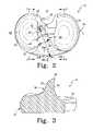
- FIG. 1is a perspective view of one embodiment of an orthopaedic knee prosthesis
- FIG. 2is a plan view of a tibial bearing of the orthopaedic knee prosthesis of FIG. 1 ;
- FIG. 3is a cross-sectional view of the tibial bearing of FIG. 2 taken generally along the line 3 - 3 of FIG. 1 ;
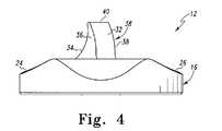
- FIG. 4is an anterior elevational view of the tibial bearing of FIG. 2 ;
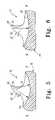
- FIG. 5is a cross-sectional view of the tibial bearing of FIG. 2 taken generally along the line 5 - 5 ;
- FIG. 6is another cross-sectional view of the tibial bearing of FIG. 2 taken generally along the line 6 - 6 ;
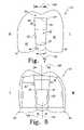
- FIG. 7is an inferior elevational view of a femoral component of the orthopaedic knee prosthesis of FIG. 1 ;
- FIG. 8is a superior elevational view of the femoral component of FIG. 7 ;
- FIG. 9is a schematic diagram of a superior plan view of the femoral component and tibial bearing of the orthopaedic knee prosthesis of FIG. 1 in an assembled configuration and positioned at about 0 degrees of flexion;
- FIG. 10is a side elevational view of the assembled orthopaedic knee prosthesis of FIG. 9 ;
- FIG. 11is a schematic diagram of a superior plan view of the assembled orthopaedic knee prosthesis of FIG. 9 positioned in deep flexion;
- FIG. 12is a side elevational view of the assembled orthopaedic knee prosthesis of FIG. 11 .
- Terms representing anatomical referencessuch as anterior, posterior, medial, lateral, superior, inferior, etcetera, may be used throughout this disclosure in reference to both the orthopaedic implants described herein and a patient's natural anatomy. Such terms have well-understood meanings in both the study of anatomy and the field of orthopaedics. Use of such anatomical reference terms in the specification and claims is intended to be consistent with their well-understood meanings unless noted otherwise.
- a posterior stabilized orthopaedic knee prosthesis 10includes a tibial insert or bearing 12 , a femoral component 14 , and, in some embodiments, a tibial tray (not shown).
- the femoral component 14is configured to articulate with the tibial bearing 12 during use.
- the knee prosthesis 10is configured to promote external axial rotation of the femoral component 14 with respect to the tibial bearing 12 during flexion of a patient's knee as discussed in more detail below.
- the orthopaedic knee prosthesis 10is illustrated as and discussed below in regard to a left knee prosthesis, which is configured to replace the left knee of a patient. However, in other embodiments, the orthopaedic knee prosthesis 10 may be embodied as a right knee prosthesis configured to replace a right knee of a patient. Regardless, it should be appreciated that the concepts and features discussed and illustrated herein are applicable to both left and right knee orthopaedic prostheses.
- the tibial bearing 12is illustratively formed from a polymer material such as ultra-high molecular weight polyethylene (UHMWPE), but may be formed from other materials, such as a ceramic material, a metallic material, a bio-engineered material, or the like, in other embodiments. Additionally, in the illustrative embodiment, the tibial bearing 12 is embodied as a fixed tibial bearing which may be limited or restricted from rotating relative to the tibial tray.
- UHMWPEultra-high molecular weight polyethylene
- the tibial bearing 12includes a platform 16 having an upper bearing surface 18 and a bottom surface 20 .
- the bearing 12may also include other devices or features to secure the tibial bearing 12 to the tibial tray in a non-rotating configuration.
- the upper bearing surface 18 of the tibial bearing 12includes a medial bearing surface 24 and a lateral bearing surface 26 .
- the medial and lateral bearing surfaces 24 , 26are configured to receive or otherwise contact corresponding medial and lateral condyles 44 , 46 of the femoral component 14 , as is discussed in greater detail below.
- the bearing surfaces 24 , 26may have concave contours in some embodiments.
- a spine 30 of the bearing 12extends upwardly from the platform 16 and is positioned between the bearing surfaces 24 , 26 .
- the spine 30includes an anterior surface 32 , a posterior cam surface 34 , a medial sidewall 36 , and a lateral sidewall 38 .
- the spine 30further includes a superior surface 40 .
- the spine 30is angled toward the medial bearing surface 24 of the platform 16 as the spine 30 extends posteriorly. In other words, the spine 30 is angled medially from the anterior surface 32 to the posterior cam surface 34 of the spine 30 in the transverse plane.
- a longitudinal axis 42 of the spine 30when viewed in the transverse plane is angled with respect to a centerline axis 45 of the platform 16 extending in the anterior-posterior direction.
- the longitudinal axis 42 and the centerline axis 45define an angle 47 therebetween.
- spine 30is configured such that the angle 47 is greater than about five degrees.
- the angle 47is about eight degrees.
- the angle 47is from about ten degrees to about fifteen degrees.
- the angle between the centerline axes 42 , 45it is within the scope of this disclosure for the angle between the centerline axes 42 , 45 to be any suitable angle.
- the angle 47 of the spine 30facilitates outward axial rotation of the femoral component 14 relative to the tibial bearing 12 .
- the amount of axial rotation of the femoral component 14is related to the degree or angle 47 of the spine 30 .
- an increased amount of rotation during flexion of the orthopaedic prosthesismay be obtained by increasing the angle 47 whereas a decreased amount of rotation during flexion may be obtained by decreasing the angle 47 .
- the spine 30 of the tibial bearing 12is also tapered in the anterior-posterior direction in the transverse plane.
- the medial and lateral surfaces, or sidewalls, 36 , 38 of the spine 30converge toward each other from the anterior surface 32 of the spine 30 to the posterior surface 34 of the spine 30 .
- the surface 36 , 38may define a respective planes, which taper toward each other and are configured to intersect each other at some location posterior to the spine 30 .
- the spine 30may have a substantially decreasing width in the anterior-posterior direction. That is, the spine 30 may have an anterior width that is greater than a posterior width.
- the spine 30may have a length when viewed in the transverse plane defined by a line segment 200 extending from a center point 202 of the posterior cam surface 34 to a center point 204 of an anterior rim 206 of the platform 16 .
- the spine 30also has an illustrative anterior width defined by a line segment 208 extending from the lateral sidewall 38 to the medial sidewall 36 .
- the line segment 208is orthogonal to and bisects the line segment 200 .
- the spine 30also has an illustrative posterior width (with respect as to the anterior width) defined by a line segment 210 extending from the lateral sidewall 38 to the medial sidewall 36 .
- the line segment 210is orthogonal to the line segment 200 and is positioned posteriorly with respect to the line segment 208 .
- the anterior width of the spine 30is greater than the posterior width of the spine 30 . That is, the length of the line segment 208 is greater than the length of the line segment 210 .
- the line segment 208may have a length that is greater than the length of the line segment 210 by at least 0.1 millimeters.
- the spine 30may be angled and tapered in the anterior-to-posterior direction.
- the posterior cam surface 34 of the spine 30is concave in the sagital plane (see FIG. 3 ) and is convex in the transverse plane (see FIG. 2 ).
- the posterior cam surface 34 of the spine 30bows outwardly posteriorly to define a convex superior edge 60 of the posterior surface 34 of the spine 30 and a convex inferior edge 62 of the posterior surface 34 of the spine 30 .
- this posterior bowing of the posterior surface 34 of the spine 30 in the transverse planealso facilitates axial rotation of the femoral component 14 relative to the tibial bearing 12 during flexion as the spine 30 of the tibial bearing 12 interacts with a posterior cam 64 of the femoral component 14 .
- the outwardly curved posterior surface 34 of the spine 30may operate to prevent edge loading during axial rotation of the femoral component 14 relative to the tibial bearing 12 .
- the medial condylar bearing surface 24 and the lateral condylar bearing surface 26 of the platform 16are concavely curved in the sagittal plane.
- the lateral condylar bearing surface 26is less constrained in the posterior region of the surface 26 with respect to the medial condylar bearing surface 24 .
- the medial bearing surface 24 in the sagittal planemay be defined by a first radius of curvature 70 .
- the posterior half of the medial bearing surface 24 in the sagittal planemay be defined by a second radius of curvature 72 .
- the lateral bearing surface 26is defined by a third radius of curvature 74 in the sagital plane.
- the posterior and anterior half of the lateral bearing surface 26 in the sagittal planeare defined by the same radius of curvature 74 .
- the second, posterior radius of curvature 72 of the posterior half of the medial bearing surface 24is smaller than the third, posterior radius of curvature of the posterior half of the lateral bearing surface 26 .
- the third radius of curvature 74may be greater than, less than, or generally equal to the first radius of curvature 70 of the medial bearing surface 24 .
- the radius of curvature 74is greater than the radius of curvature 70 by at least 0.5 millimeters.
- the posterior half of the lateral bearing surface 26it is within the scope of this disclosure for the posterior half of the lateral bearing surface 26 to have any suitable radius of curvature greater than the radius of curvature of the posterior half of the medial bearing surface 24 . Accordingly, the posterior region of the medial bearing surface 24 is more constrained than a posterior region of the lateral bearing surface 26 . As such, the less constrained posterior region of the lateral bearing surface 26 facilitates outward axial rotation of the femoral component 14 in deep or late flexion, as is discussed in greater detail below.
- the femoral component 14is configured to be coupled to a surgically-prepared surface of the distal end of a patient's femur (not shown).
- the femoral component 14may be secured to the patient's femur via use of bone adhesive or other attachment means.
- the femoral component 12is illustratively formed from a metallic material such as cobalt-chromium or titanium, but may be formed from other materials, such as a ceramic material, a polymer material, a bio-engineered material, or the like, in other embodiments.
- the femoral component 14includes an articulating surface 80 having a pair of spaced-apart medial and lateral condyles 44 , 46 having respective medial and lateral condyle surfaces 88 , 90 .
- the condyles 44 , 46replace the natural condyles of the patient- 3 s femur and are configured to articulate on the corresponding bearing surfaces 24 , 26 of the platform 16 of the tibial bearing 12 .
- the condyles 44 , 46are spaced-apart to define an intracondyle notch or recess 82 therebetween.
- the posterior cam 64is positioned in the intracondyle notch 82 .
- the posterior cam 64is located toward the posterior side of the femoral component 14 and includes a cam surface 87 configured to engage or otherwise contact the posterior cam surface 34 of spine 30 of the tibial bearing 12 during flexion as described in more detail below.
- the posterior cam surface 87 of the femoral componentis concavely curved in the medial-lateral direction as illustrated in FIG. 7 .
- the posterior cam surface 34 of the spine 30is convex in the traverse plane as illustrated in FIG. 4 .
- the radius of curvature of the cam surfaces 87 , 34may be dependent upon a number of criteria such as the size of the prosthesis, the shape or geometry of the articulating surface of the spine 30 of the tibial implant 12 , the shape or geometry of the articulating surface of the cam 64 , and/or the like.
- the intracondylar notch 82is defined by a cam box 92 .
- the cam box 92includes an inner medial wall 96 , which is connected to a lateral edge of the medial condyle 90 , and an inner lateral wall 94 , which is connected to a medial edge of the lateral condyle 88 .
- the cam box 92also includes an anterior wall 86 , which may be embodied as an anterior cam in some embodiments. In such embodiments, the anterior cam includes an anterior cam surface 102 .
- the cam box 92also includes the posterior cam 64 , which forms an inner posterior “wall” of the cam box 92 .
- the cam box 92also includes a superior wall 98 .
- the superior wall 98includes an aperture 100 formed therethrough.
- the aperture 100is configured to receive a femoral stem (not shown) to be received with in a bore drilled into the femur of a patient.
- the cam box 92includes an outer medial sidewall 97 and an outer lateral sidewall 95
- the cam surface 102may be generally straight in the medial-lateral direction, as shown in FIG. 7 .
- the cam surface 102 of the anterior cam 86may interact with the anterior surface 32 of the spine 30 of the tibial bearing 12 during extension.
- the femoral componentincludes the cam box 92 having the convex anterior cam 86
- an anterior camhaving another suitable cam surface to interact with the corresponding anterior surface of the spine of the tibial bearing.
- the inner medial and lateral sidewalls 96 , 94 of the cam box 92are tapered in the transverse plane.
- the sidewalls 94 , 96taper toward each other from the anterior side of the femoral component 14 to the posterior side of the femoral component 14 .
- the medial sidewall 96is angled with respect to a longitudinal axis 104 of the cam box 92 of the femoral component 14 .
- the lateral sidewall 94is similarly angled with respect to the longitudinal axis 104 of the cam box 92 of the femoral component 14 .
- the cam box 92has a posterior width 106 and an anterior width 108 .
- the posterior width 106may be equal to a width of the posterior cam 64 between the medial sidewall 96 and the lateral sidewall 94 .
- the anterior width 108may be equal to a width of the anterior wall 86 between the medial sidewall 96 and the lateral sidewall 94 .
- the anterior width 108is greater than the posterior width 106 .
- the anterior width 108may be greater than the posterior width 106 by 0.5 millimeters or more.
- the distance between the medial and lateral sidewalls 96 , 94 of the cam box 92which is perpendicular to the longitudinal axis 104 of the cam box 92 , decreases in a posterior direction.
- a medial-lateral width of the cam box 92 between the sidewalls 94 , 96is greater than a medial-lateral width of the spine 30 along similar anterior-posterior positions.
- any width of the cam box 92 taken generally in the anterior half of the cam box 92is wider than the widest portion, i.e., the anterior width 208 , of the spine 30 . Therefore, the spine 30 generally does not contact the sidewalls 94 , 96 of the cam box 92 in early flexion in order to allow the femoral component 14 to remain in a neutral axial position, i.e., having no rotation of the femoral component 14 on the tibial component 12 , during early flexion.
- the femoral component 14may remain in a neutral axial position during the first 30 degrees of knee flexion.
- a knee prosthesiswherein the femoral component remains in a neutral axial position during any suitable portion of the knee flexion.
- a knee prosthesiswhich facilitates the outward axial rotation of the femoral component at some time before or after 30 degrees of knee flexion.
- the femoral component 14articulates on the tibial bearing 12 and is urged to rotate outwardly axially in later flexion.
- the angled and tapered spine 30 of the tibial bearing 12 as well as the tapered cam box 92 of the femoral componentcooperate to promote outward axial rotation of the femoral component 14 on the tibial bearing 12 .
- the less constrained posterior portion of the lateral bearing surface 26also promotes such outward axial rotation of the femoral component during flexion.
- cam surface 34 of the spine 30is curved posteriorly in the transverse plane and the posterior cam 64 of the femoral component 12 articulates on the cam surfaces 34 in the transverse plane such that rotation of the femoral component 14 about the spine 30 is further facilitated.
- the angled and tapered spine 30 of the tibial bearing 12cooperates with the tapered cam box 92 during flexion to facilitate axial rotation of the femoral component 14 on the tibial component 12 , as shown in FIGS. 11 and 12 .
- the spine 30is positioned within the intracondyle notch 82 , which is substantially defined by the cam box 92 , of the femoral component 14 .
- the cam box 92is sufficiently wide to allow the femoral component 14 to stay in a neutral axial position, i.e., having 0 degrees of rotation, relative to the tibial bearing 12 , during early knee flexion. For example, as shown in FIGS.
- the femoral component 14is in an axial neutral position at 0 degrees of flexion. This axially neutral position is maintained throughout approximately the first 30 degrees of flexion, as noted above.
- the cam box 92is wide enough to prevent the spine 30 from engaging the sidewalls 94 , 96 of the cam box 92 during early flexion.
- the sidewalls 94 , 96 of the cam box 92begin to engage with the sidewalls 36 , 38 of the spine 30 .
- the angled spine 30interacts with the cam box 92 to guide the femoral component 14 and axially rotate the femoral component 14 outwardly on the tibial bearing 12 .
- the tapered sidewalls 36 , 38 of the spine 30 and the tapered sidewalls 94 , 96 of the cam box 92cooperate with each other to suitably accommodate the angled spine 30 .
- the angled spine 30facilitates rotation of the femoral component 14 outwardly, or in a generally counter-clockwise direction 120 , as shown in FIG. 11 , during later flexion of the knee.
- the sidewalls 94 , 96 of the cam box 92 and the sidewalls 36 , 38 of the spine 30continue to engage each other resulting in a gradually increased axial rotation of the femoral component 14 .
- this processis facilitated by the less-constrained posterior portion of the lateral bearing surface 26 of the tibial bearing 12 .
- the amount of rotation between the femoral component 14 and the tibial bearing 12 during flexionmay be adjusted based on the degree of the angle 47 of the spine 30 between the centerline axis of the tibial bearing 45 and the centerline axis of the spine 42 .
- an increased amount of rotation of the femoral component 14 on the tibial bearing 12may be obtained by increasing the angle 47 of the spine 30 .
- the radii of curvature of the medial and lateral bearing surfaces 24 , 26 of the tibial bearing 12further cooperate with the femoral component 14 to promote the outward axial rotation of the femoral component 14 on the tibial component 12 during flexion.
- the posterior portion of the lateral bearing surface 26is less constrained than the posterior portion of the medial bearing surface 24 .
- the posterior radius of curvature 74 of the lateral bearing surface 26is greater than the posterior radius of curvature 72 of the medial bearing surface 26 , thus providing a less constrained posterior bearing surface 26 .
- the lateral condyle 46 of the femoral component 14is less constrained within the lateral bearing surface 26 of the tibial bearing 12 when the lateral condyle 46 is engaged with the posterior portion of the lateral bearing surface 26 . Accordingly, therefore, the lateral condyle 46 of the femoral component 14 is able to move posteriorly on the lateral bearing surface 26 , as shown in deep flexion in FIGS. 11 and 12 , to promote the outward axial rotation of the femoral component 14 .
- the femoral component 14 and the tibial bearing 12are configured such that the posterior cam 64 of the femoral component 14 contacts the spine 30 of the tibial bearing 12 during flexion.
- the concave cam surface 87 of the posterior cam 64 of the femoral component 14contacts the convex cam surface 34 of the spine 30 . Accordingly, the interaction between the cam surfaces 34 , 87 allows the femoral component 14 to rotate axially relative to the tibial bearing 12 during flexion.
- the radius of curvature in the medial-lateral direction of the concave cam surface 87may be substantially equal to, greater than, or less than the radius of curvature in the transverse plane of the convex cam surface 34 of the spine 30 .
- the concave cam surface 87 of the posterior cam 64operates to increase the contact area between the posterior surface 34 of the spine 30 and the cam 64 . This increase in contact area may decrease the stress between the cam surfaces 34 , 87 during axial rotation of the femoral component 14 relative to the tibial bearing 12 .
- the amount of rotation between the femoral component 14 and the tibial bearing 14 during flexionmay be adjusted based on the radius of curvatures in the transverse plane of the cam surfaces 34 , 87 .
- an increased amount of rotation during flexion of the orthopaedic prosthesismay be obtained by decreasing the radius of curvature in the transverse plane of the convex cam surface 87 .
- the cam surface 87 of the posterior cam 64is curved posteriorly, the cam surface 87 may also be substantially planar in the medial-lateral direction in some embodiments.
- the posterior cam 64 of the femoral component 14when the orthopaedic prosthesis 10 is extended or otherwise not in flexion (e.g., a neutral position of about 0 degrees flexion), the posterior cam 64 of the femoral component 14 is not in contact with the spine 30 of the tibial bearing 12 . However, late flexion the posterior cam 64 of the femoral component 14 contacts the spine 30 of the tibial bearing 12 . Illustratively, for example, in some embodiments, the posterior cam 64 may engage the spine 30 at approximately 70 degrees of flexion. As noted above, during late or deep flexion of the orthopaedic prosthesis 10 , the convex cam surface 34 of the spine 30 maintains contact with the concave cam surface 87 of the femoral component 14 . It should be appreciated that contact between the posterior cam 64 and the spine 30 is maintained during late flexion.
- contact between the concave cam surface 87 of the posterior cam 64 of the femoral component 14 and the convex cam surface 34 of the spine 30 during late flexionmay facilitate rollback of the femoral component 14 on the platform 16 of the tibial bearing 12 .
- the femoral component 14may rotate about the spine 30 in the generally counter-clockwise or outward axial direction in the transverse plane as indicated by arrow 120 in FIG. 11 .
- the amount of rotation between the femoral component 14 and the tibial bearing 12 during flexionmay be adjusted based on the radius of curvatures in the transverse plane of the cam surfaces 34 , 87 .
- the amount of axial rotation of the femoral component 14 relative to the tibial bearing 12is substantially dependent upon the spine angle 47 and the interaction between the sidewalls 36 , 38 of the spine 30 and the sidewalls 94 , 96 of the cam box 92 .
- many features of the prosthesis 10cooperate to facilitate outward axial rotation of the femoral component 14 on the tibial bearing 12 . While these features are shown and described on a common prosthesis 10 , it is within the scope of this disclosure to include a knee prosthesis having only one or more of the above-disclosed features which promote the outward axial rotation of the femoral component 14 and which cooperate with and accommodate such features.
Landscapes
- Health & Medical Sciences (AREA)
- Orthopedic Medicine & Surgery (AREA)
- Physical Education & Sports Medicine (AREA)
- Cardiology (AREA)
- Oral & Maxillofacial Surgery (AREA)
- Transplantation (AREA)
- Engineering & Computer Science (AREA)
- Biomedical Technology (AREA)
- Heart & Thoracic Surgery (AREA)
- Vascular Medicine (AREA)
- Life Sciences & Earth Sciences (AREA)
- Animal Behavior & Ethology (AREA)
- General Health & Medical Sciences (AREA)
- Public Health (AREA)
- Veterinary Medicine (AREA)
- Prostheses (AREA)
Abstract
Description
Claims (13)
Priority Applications (7)
| Application Number | Priority Date | Filing Date | Title |
|---|---|---|---|
| US12/165,424US8075626B2 (en) | 2008-06-30 | 2008-06-30 | Orthopaedic knee prosthesis having increased axial-rotation |
| JP2009153345AJP5442334B2 (en) | 2008-06-30 | 2009-06-29 | Orthopedic knee joint prosthesis with increased axial rotation |
| AU2009202629AAU2009202629B2 (en) | 2008-06-30 | 2009-06-29 | Orthopaedic knee prosthesis having increased axial-rotation |
| EP09164194.4AEP2143403B1 (en) | 2008-06-30 | 2009-06-30 | Knee Prosthesis |
| DK09164194.4TDK2143403T3 (en) | 2008-06-30 | 2009-06-30 | knee prosthesis |
| CN200910163990.XACN101658446B (en) | 2008-06-30 | 2009-06-30 | Orthopaedic knee prosthesis having increased axial-rotation |
| ES09164194.4TES2456337T3 (en) | 2008-06-30 | 2009-06-30 | Knee prosthesis |
Applications Claiming Priority (1)
| Application Number | Priority Date | Filing Date | Title |
|---|---|---|---|
| US12/165,424US8075626B2 (en) | 2008-06-30 | 2008-06-30 | Orthopaedic knee prosthesis having increased axial-rotation |
Publications (2)
| Publication Number | Publication Date |
|---|---|
| US20090326663A1 US20090326663A1 (en) | 2009-12-31 |
| US8075626B2true US8075626B2 (en) | 2011-12-13 |
Family
ID=41349351
Family Applications (1)
| Application Number | Title | Priority Date | Filing Date |
|---|---|---|---|
| US12/165,424Expired - Fee RelatedUS8075626B2 (en) | 2008-06-30 | 2008-06-30 | Orthopaedic knee prosthesis having increased axial-rotation |
Country Status (7)
| Country | Link |
|---|---|
| US (1) | US8075626B2 (en) |
| EP (1) | EP2143403B1 (en) |
| JP (1) | JP5442334B2 (en) |
| CN (1) | CN101658446B (en) |
| AU (1) | AU2009202629B2 (en) |
| DK (1) | DK2143403T3 (en) |
| ES (1) | ES2456337T3 (en) |
Cited By (48)
| Publication number | Priority date | Publication date | Assignee | Title |
|---|---|---|---|---|
| US20100305710A1 (en)* | 2009-05-28 | 2010-12-02 | Biomet Manufacturing Corp. | Knee Prosthesis |
| US20110125279A1 (en)* | 2009-11-16 | 2011-05-26 | New York Society For The Ruptured And Crippled Maintaining The Hospital For Special Surgery | Constrained condylar knee device |
| US20110125275A1 (en)* | 2009-11-16 | 2011-05-26 | New York Society For The Ruptured And Crippled Maintaining The Hospital For Special Surgery | Prosthetic condylar joints with articulating bearing surfaces having a translating contact point during rotation thereof |
| US20120136452A1 (en)* | 2009-07-10 | 2012-05-31 | Medizinische Hochschule Hannover | Knee joint prosthesis and related method |
| US20130018477A1 (en)* | 2011-07-13 | 2013-01-17 | The General Hospital Corporation D/B/A Massachusetts General Hospital | Methods and Devices for Knee Joint Replacement with Anterior Cruciate Ligament Substitution |
| US20130226305A1 (en)* | 2010-09-10 | 2013-08-29 | Zimmer Gmbh | Femoral prosthesis with medialized patellar groove |
| US8894715B2 (en) | 2009-05-28 | 2014-11-25 | Biomet Manufacturing, Llc | Knee prosthesis |
| US9308095B2 (en) | 2011-06-16 | 2016-04-12 | Zimmer, Inc. | Femoral component for a knee prosthesis with improved articular characteristics |
| US9592127B2 (en) | 2005-12-15 | 2017-03-14 | Zimmer, Inc. | Distal femoral knee prostheses |
| US10070966B2 (en) | 2011-06-16 | 2018-09-11 | Zimmer, Inc. | Femoral component for a knee prosthesis with bone compacting ridge |
| US10092288B2 (en) | 2006-02-03 | 2018-10-09 | Biomet Sports Medicine, Llc | Method and apparatus for coupling soft tissue to a bone |
| US10098629B2 (en) | 2006-02-03 | 2018-10-16 | Biomet Sports Medicine, Llc | Method and apparatus for coupling soft tissue to a bone |
| US10130375B2 (en) | 2014-07-31 | 2018-11-20 | Zimmer, Inc. | Instruments and methods in performing kinematically-aligned total knee arthroplasty |
| US10136997B2 (en) | 2015-09-29 | 2018-11-27 | Zimmer, Inc. | Tibial prosthesis for tibia with varus resection |
| US10265159B2 (en) | 2011-11-03 | 2019-04-23 | Biomet Sports Medicine, Llc | Method and apparatus for stitching tendons |
| US10265064B2 (en) | 2004-11-05 | 2019-04-23 | Biomet Sports Medicine, Llc | Soft tissue repair device and method |
| US10363028B2 (en) | 2011-11-10 | 2019-07-30 | Biomet Sports Medicine, Llc | Method for coupling soft tissue to a bone |
| US10368856B2 (en) | 2011-11-10 | 2019-08-06 | Biomet Sports Medicine, Llc | Apparatus for coupling soft tissue to a bone |
| US10383738B2 (en)* | 1999-06-16 | 2019-08-20 | Btg International Limited | Tibial component |
| US10398428B2 (en) | 2006-02-03 | 2019-09-03 | Biomet Sports Medicine, Llc | Method and apparatus for coupling anatomical features |
| US10398430B2 (en) | 2006-09-29 | 2019-09-03 | Biomet Sports Medicine, Llc | Method for implanting soft tissue |
| US10441429B2 (en) | 2011-06-16 | 2019-10-15 | Zimmer, Inc. | Femoral component for a knee prosthesis with improved articular characteristics |
| US10517587B2 (en) | 2006-02-03 | 2019-12-31 | Biomet Sports Medicine, Llc | Method and apparatus for forming a self-locking adjustable loop |
| US10517714B2 (en) | 2006-09-29 | 2019-12-31 | Biomet Sports Medicine, Llc | Ligament system for knee joint |
| US10603029B2 (en) | 2006-02-03 | 2020-03-31 | Biomet Sports Medicine, Llc | Method and apparatus for coupling soft tissue to bone |
| US10610217B2 (en) | 2006-09-29 | 2020-04-07 | Biomet Sports Medicine, Llc | Method and apparatus for forming a self-locking adjustable loop |
| US10675073B2 (en) | 2006-02-03 | 2020-06-09 | Biomet Sports Medicine, Llc | Method and apparatus for sternal closure |
| US10695045B2 (en) | 2006-09-29 | 2020-06-30 | Biomet Sports Medicine, Llc | Method and apparatus for attaching soft tissue to bone |
| US10702259B2 (en) | 2006-02-03 | 2020-07-07 | Biomet Sports Medicine, Llc | Soft tissue repair assembly and associated method |
| US10729423B2 (en) | 2007-04-10 | 2020-08-04 | Biomet Sports Medicine, Llc | Adjustable knotless loops |
| US10729421B2 (en) | 2006-02-03 | 2020-08-04 | Biomet Sports Medicine, Llc | Method and apparatus for soft tissue fixation |
| US10743925B2 (en) | 2006-09-29 | 2020-08-18 | Biomet Sports Medicine, Llc | Fracture fixation device |
| US10758221B2 (en) | 2013-03-14 | 2020-09-01 | Biomet Sports Medicine, Llc | Scaffold for spring ligament repair |
| US10835232B2 (en) | 2006-09-29 | 2020-11-17 | Biomet Sports Medicine, Llc | Fracture fixation device |
| US10932770B2 (en) | 2006-02-03 | 2021-03-02 | Biomet Sports Medicine, Llc | Soft tissue repair device and associated methods |
| US10973507B2 (en) | 2006-02-03 | 2021-04-13 | Biomet Sports Medicine, Llc | Method and apparatus for coupling soft tissue to a bone |
| US10987099B2 (en) | 2006-02-03 | 2021-04-27 | Biomet Sports Medicine, Llc | Method for tissue fixation |
| US11039826B2 (en) | 2006-02-03 | 2021-06-22 | Biomet Sports Medicine, Llc | Method and apparatus for forming a self-locking adjustable loop |
| US11065103B2 (en) | 2006-02-03 | 2021-07-20 | Biomet Sports Medicine, Llc | Method and apparatus for fixation of an ACL graft |
| US11259794B2 (en) | 2006-09-29 | 2022-03-01 | Biomet Sports Medicine, Llc | Method for implanting soft tissue |
| US11259792B2 (en) | 2006-02-03 | 2022-03-01 | Biomet Sports Medicine, Llc | Method and apparatus for coupling anatomical features |
| US11311287B2 (en) | 2006-02-03 | 2022-04-26 | Biomet Sports Medicine, Llc | Method for tissue fixation |
| US11564800B2 (en)* | 2009-05-07 | 2023-01-31 | Depuy Ireland Unlimited Company | Anterior stabilized knee implant |
| US11612391B2 (en) | 2007-01-16 | 2023-03-28 | Biomet Sports Medicine, Llc | Soft tissue repair device and associated methods |
| US12096928B2 (en) | 2009-05-29 | 2024-09-24 | Biomet Sports Medicine, Llc | Method and apparatus for coupling soft tissue to a bone |
| US12245759B2 (en) | 2008-08-22 | 2025-03-11 | Biomet Sports Medicine, Llc | Method and apparatus for coupling soft tissue to bone |
| US12329373B2 (en) | 2011-05-02 | 2025-06-17 | Biomet Sports Medicine, Llc | Method and apparatus for soft tissue fixation |
| US12419632B2 (en) | 2008-08-22 | 2025-09-23 | Biomet Sports Medicine, Llc | Method and apparatus for coupling anatomical features |
Families Citing this family (50)
| Publication number | Priority date | Publication date | Assignee | Title |
|---|---|---|---|---|
| US6558426B1 (en) | 2000-11-28 | 2003-05-06 | Medidea, Llc | Multiple-cam, posterior-stabilized knee prosthesis |
| US9301845B2 (en) | 2005-06-15 | 2016-04-05 | P Tech, Llc | Implant for knee replacement |
| EP1996122B1 (en) | 2006-03-21 | 2012-11-21 | DePuy (Ireland) | Moment induced total arthroplasty prosthetic |
| WO2008058205A1 (en) | 2006-11-07 | 2008-05-15 | Biomedflex, Llc | Medical implants |
| US8512413B2 (en) | 2006-11-07 | 2013-08-20 | Biomedflex, Llc | Prosthetic knee joint |
| US9005307B2 (en) | 2006-11-07 | 2015-04-14 | Biomedflex, Llc | Prosthetic ball-and-socket joint |
| US8029574B2 (en) | 2006-11-07 | 2011-10-04 | Biomedflex Llc | Prosthetic knee joint |
| US20110166671A1 (en) | 2006-11-07 | 2011-07-07 | Kellar Franz W | Prosthetic joint |
| US8308812B2 (en) | 2006-11-07 | 2012-11-13 | Biomedflex, Llc | Prosthetic joint assembly and joint member therefor |
| US8070823B2 (en) | 2006-11-07 | 2011-12-06 | Biomedflex Llc | Prosthetic ball-and-socket joint |
| US8128703B2 (en) | 2007-09-28 | 2012-03-06 | Depuy Products, Inc. | Fixed-bearing knee prosthesis having interchangeable components |
| US8632600B2 (en) | 2007-09-25 | 2014-01-21 | Depuy (Ireland) | Prosthesis with modular extensions |
| US9204967B2 (en) | 2007-09-28 | 2015-12-08 | Depuy (Ireland) | Fixed-bearing knee prosthesis having interchangeable components |
| US8187335B2 (en) | 2008-06-30 | 2012-05-29 | Depuy Products, Inc. | Posterior stabilized orthopaedic knee prosthesis having controlled condylar curvature |
| US9168145B2 (en) | 2008-06-30 | 2015-10-27 | Depuy (Ireland) | Posterior stabilized orthopaedic knee prosthesis having controlled condylar curvature |
| US8828086B2 (en) | 2008-06-30 | 2014-09-09 | Depuy (Ireland) | Orthopaedic femoral component having controlled condylar curvature |
| US9119723B2 (en) | 2008-06-30 | 2015-09-01 | Depuy (Ireland) | Posterior stabilized orthopaedic prosthesis assembly |
| US8192498B2 (en) | 2008-06-30 | 2012-06-05 | Depuy Products, Inc. | Posterior cructiate-retaining orthopaedic knee prosthesis having controlled condylar curvature |
| US8236061B2 (en) | 2008-06-30 | 2012-08-07 | Depuy Products, Inc. | Orthopaedic knee prosthesis having controlled condylar curvature |
| US8206451B2 (en) | 2008-06-30 | 2012-06-26 | Depuy Products, Inc. | Posterior stabilized orthopaedic prosthesis |
| US8202323B2 (en)* | 2008-07-16 | 2012-06-19 | Depuy Products, Inc. | Knee prostheses with enhanced kinematics |
| US9078755B2 (en)* | 2009-02-25 | 2015-07-14 | Zimmer, Inc. | Ethnic-specific orthopaedic implants and custom cutting jigs |
| US9011547B2 (en) | 2010-01-21 | 2015-04-21 | Depuy (Ireland) | Knee prosthesis system |
| ES2632995T3 (en) | 2010-07-24 | 2017-09-18 | Zimmer, Inc. | Asymmetric tibia components for a knee prosthesis |
| US8764840B2 (en) | 2010-07-24 | 2014-07-01 | Zimmer, Inc. | Tibial prosthesis |
| US8591594B2 (en) | 2010-09-10 | 2013-11-26 | Zimmer, Inc. | Motion facilitating tibial components for a knee prosthesis |
| US8287601B2 (en) | 2010-09-30 | 2012-10-16 | Depuy Products, Inc. | Femoral component of a knee prosthesis having an angled cement pocket |
| US8317870B2 (en) | 2010-09-30 | 2012-11-27 | Depuy Products, Inc. | Tibial component of a knee prosthesis having an angled cement pocket |
| ES2443827T3 (en)* | 2010-10-05 | 2014-02-20 | Aesculap Ag | Knee Joint Endoprosthesis |
| US8603101B2 (en) | 2010-12-17 | 2013-12-10 | Zimmer, Inc. | Provisional tibial prosthesis system |
| US8728167B2 (en)* | 2011-01-10 | 2014-05-20 | Howmedica Osteonics Corp. | Bicruciate retaining tibial baseplate design and method of implantation |
| CN103327937B (en)* | 2011-01-27 | 2017-08-08 | 史密夫和内修有限公司 | constrained knee prosthesis |
| US8551179B2 (en) | 2011-06-16 | 2013-10-08 | Zimmer, Inc. | Femoral prosthesis system having provisional component with visual indicators |
| AU2012271243B2 (en)* | 2011-06-16 | 2015-05-07 | Zimmer, Inc. | Femoral component for a knee prosthesis with improved articular characteristics |
| EP3175824B1 (en) | 2011-11-18 | 2019-01-02 | Zimmer, Inc. | Tibial bearing component for a knee prosthesis with improved articular characteristics |
| ES2585838T3 (en) | 2011-11-21 | 2016-10-10 | Zimmer, Inc. | Tibial base plate with asymmetric placement of fixing structures |
| IN2014DN07145A (en) | 2012-01-30 | 2015-04-24 | Zimmer Inc | |
| US9289306B2 (en) | 2013-03-15 | 2016-03-22 | Catalyst Orthopaedics Llc | Humeral arthroplasty |
| US9925052B2 (en) | 2013-08-30 | 2018-03-27 | Zimmer, Inc. | Method for optimizing implant designs |
| USD735338S1 (en) | 2013-10-31 | 2015-07-28 | Catalyst Orthopaedics Llc | Humeral component for shoulder arthroplasty |
| GB2521871B (en)* | 2014-01-07 | 2020-04-01 | James Wallace Mcminn Derek | Knee prosthesis with congruent and incongruent condyle bearing surfaces |
| US11612487B2 (en) | 2014-01-07 | 2023-03-28 | Derek James Wallace McMinn | Knee prosthesis |
| US10463498B2 (en)* | 2014-09-23 | 2019-11-05 | Tecres S.P.A. | Constrained prosthesis for the knee joint |
| WO2017053196A1 (en) | 2015-09-21 | 2017-03-30 | Zimmer, Inc. | Prosthesis system including tibial bearing component |
| US10231840B2 (en) | 2016-07-27 | 2019-03-19 | Howmedica Osteonics Corp. | Low profile tibial baseplate with fixation members |
| US10179052B2 (en) | 2016-07-28 | 2019-01-15 | Depuy Ireland Unlimited Company | Total knee implant prosthesis assembly and method |
| US10675153B2 (en) | 2017-03-10 | 2020-06-09 | Zimmer, Inc. | Tibial prosthesis with tibial bearing component securing feature |
| WO2018208612A1 (en) | 2017-05-12 | 2018-11-15 | Zimmer, Inc. | Femoral prostheses with upsizing and downsizing capabilities |
| US11426282B2 (en) | 2017-11-16 | 2022-08-30 | Zimmer, Inc. | Implants for adding joint inclination to a knee arthroplasty |
| US10835380B2 (en) | 2018-04-30 | 2020-11-17 | Zimmer, Inc. | Posterior stabilized prosthesis system |
Citations (14)
| Publication number | Priority date | Publication date | Assignee | Title |
|---|---|---|---|---|
| US4959071A (en) | 1988-02-03 | 1990-09-25 | Biomet, Inc. | Partially stabilized knee prosthesis |
| US5147405A (en) | 1990-02-07 | 1992-09-15 | Boehringer Mannheim Corporation | Knee prosthesis |
| US5192328A (en) | 1989-09-29 | 1993-03-09 | Winters Thomas F | Knee joint replacement apparatus |
| US5370699A (en) | 1993-01-21 | 1994-12-06 | Orthomet, Inc. | Modular knee joint prosthesis |
| US6013103A (en) | 1996-07-11 | 2000-01-11 | Wright Medical Technology, Inc. | Medial pivot knee prosthesis |
| EP0970667A1 (en) | 1998-07-08 | 2000-01-12 | Johnson & Johnson Professional, Inc. | Rotatable and translatable joint prosthesis with posterior stabilization |
| EP1378216A2 (en) | 2002-07-01 | 2004-01-07 | Biomet, Inc. | Floating bearing knee joint prosthesis with a fixed tibial post |
| EP1400220A1 (en) | 2002-09-12 | 2004-03-24 | DePuy Products, Inc. | Posterior stabilized knee with varus-valgus constraint |
| WO2004058108A1 (en) | 2002-12-20 | 2004-07-15 | Smith & Nephew, Inc. | High performance knee prostheses |
| US20050055102A1 (en) | 2003-05-12 | 2005-03-10 | Alain Tornier | Set of prosthetic elements for a tibial prosthetic assembly |
| EP1591082A2 (en) | 2004-03-17 | 2005-11-02 | Nakashima Propeller Co., Ltd. | An artificial knee joint |
| US6986791B1 (en) | 2003-04-15 | 2006-01-17 | Biomet Manufacturing Corp. | Knee prosthesis with moveable post |
| US20060265078A1 (en) | 2005-05-19 | 2006-11-23 | Mcminn Derek J W | Knee prosthesis |
| US20060265080A1 (en) | 2005-05-19 | 2006-11-23 | Mcminn Derek J W | Knee prosthesis |
Family Cites Families (1)
| Publication number | Priority date | Publication date | Assignee | Title |
|---|---|---|---|---|
| CN101214175B (en)* | 2008-01-17 | 2011-03-23 | 四川大学 | Knee joint endoprosthesis |
- 2008
- 2008-06-30USUS12/165,424patent/US8075626B2/ennot_activeExpired - Fee Related
- 2009
- 2009-06-29JPJP2009153345Apatent/JP5442334B2/enactiveActive
- 2009-06-29AUAU2009202629Apatent/AU2009202629B2/ennot_activeCeased
- 2009-06-30DKDK09164194.4Tpatent/DK2143403T3/enactive
- 2009-06-30ESES09164194.4Tpatent/ES2456337T3/enactiveActive
- 2009-06-30CNCN200910163990.XApatent/CN101658446B/ennot_activeExpired - Fee Related
- 2009-06-30EPEP09164194.4Apatent/EP2143403B1/enactiveActive
Patent Citations (16)
| Publication number | Priority date | Publication date | Assignee | Title |
|---|---|---|---|---|
| US4959071A (en) | 1988-02-03 | 1990-09-25 | Biomet, Inc. | Partially stabilized knee prosthesis |
| US5192328A (en) | 1989-09-29 | 1993-03-09 | Winters Thomas F | Knee joint replacement apparatus |
| US5147405A (en) | 1990-02-07 | 1992-09-15 | Boehringer Mannheim Corporation | Knee prosthesis |
| US5370699A (en) | 1993-01-21 | 1994-12-06 | Orthomet, Inc. | Modular knee joint prosthesis |
| US6013103A (en) | 1996-07-11 | 2000-01-11 | Wright Medical Technology, Inc. | Medial pivot knee prosthesis |
| EP0970667A1 (en) | 1998-07-08 | 2000-01-12 | Johnson & Johnson Professional, Inc. | Rotatable and translatable joint prosthesis with posterior stabilization |
| US6080195A (en) | 1998-07-08 | 2000-06-27 | Johnson & Johnson Professional, Inc. | Rotatable and translatable joint prosthesis with posterior stabilization |
| EP1378216A2 (en) | 2002-07-01 | 2004-01-07 | Biomet, Inc. | Floating bearing knee joint prosthesis with a fixed tibial post |
| EP1400220A1 (en) | 2002-09-12 | 2004-03-24 | DePuy Products, Inc. | Posterior stabilized knee with varus-valgus constraint |
| WO2004058108A1 (en) | 2002-12-20 | 2004-07-15 | Smith & Nephew, Inc. | High performance knee prostheses |
| US7326252B2 (en) | 2002-12-20 | 2008-02-05 | Smith & Nephew, Inc. | High performance knee prostheses |
| US6986791B1 (en) | 2003-04-15 | 2006-01-17 | Biomet Manufacturing Corp. | Knee prosthesis with moveable post |
| US20050055102A1 (en) | 2003-05-12 | 2005-03-10 | Alain Tornier | Set of prosthetic elements for a tibial prosthetic assembly |
| EP1591082A2 (en) | 2004-03-17 | 2005-11-02 | Nakashima Propeller Co., Ltd. | An artificial knee joint |
| US20060265078A1 (en) | 2005-05-19 | 2006-11-23 | Mcminn Derek J W | Knee prosthesis |
| US20060265080A1 (en) | 2005-05-19 | 2006-11-23 | Mcminn Derek J W | Knee prosthesis |
Non-Patent Citations (12)
| Title |
|---|
| Advance Stemmed Medical Pivot, Wright Medical Technology, 3 pages, http:/www.wmt.com/Downloads/ADVANCE%C2%AE%20Stemmed%20Medial%20Pivot%20broc%20MK419-701.pdf. |
| Contact stress at the post-cam mechanism in posterior-stabilized total knee arthroplasty, Nakayama et al., (2005), 6 pgs. |
| European Search Report for European Patent Application No. 09164194.4-1526, Dec. 9, 2009, 6 pgs. |
| European Search Report for European Patent Application No. 09164242.1-2310/2140838, Jan. 19, 2010, 10 pgs. |
| In Vivo Determination of Posterior Femoral Rollback for Subjects Having a NexGen Posterior Cruciate-Retaining Total Knee Arthroplasty, Bertin et al., (2002), 9 pgs. |
| Kinematic Comparison Between Mobile-Bearing and Fixed-Bearing Inserts in NexGen Legacy Posterior Stabilized Flex Total Knee Arthroplasty, Shi et al., (2008), 6 pgs. |
| NexGen Complete Knee Solution Cruciate Retaining Knee (CR), Zimmer, 2 pages, http://www.zimmer.com/z/ctl/op/global/action/1/id/356/template/PC/prcat/P3/prod/y. |
| Partial European Search Report for European Patent Application No. 09164242.1-2310, Oct. 19, 2009, 5 pgs. |
| Performance Knee System, BIOMET, 1 page, http://www.biometgermany.de/medhome-uk/knee/primary/performance. |
| Scorpio NRG, The Evolution in High Performance Knee System, Stryker Orthopaedics, 16 pages, http://www.stryker.com/stellent/groups/public/documents/web-prod/023608.pdf. |
| Stress Analysis of PS Type Knee Prostheses under Deep Flexion, Todo et al., (2007), 9 pgs. |
| Stryker Howmedica Osteonics, Scorpio Flex Single Axis Knee, 2002, 3 pages. |
Cited By (99)
| Publication number | Priority date | Publication date | Assignee | Title |
|---|---|---|---|---|
| US10383738B2 (en)* | 1999-06-16 | 2019-08-20 | Btg International Limited | Tibial component |
| US11109857B2 (en) | 2004-11-05 | 2021-09-07 | Biomet Sports Medicine, Llc | Soft tissue repair device and method |
| US10265064B2 (en) | 2004-11-05 | 2019-04-23 | Biomet Sports Medicine, Llc | Soft tissue repair device and method |
| US9592127B2 (en) | 2005-12-15 | 2017-03-14 | Zimmer, Inc. | Distal femoral knee prostheses |
| US10433966B2 (en) | 2005-12-15 | 2019-10-08 | Zimmer, Inc. | Distal femoral knee prostheses |
| US11471147B2 (en) | 2006-02-03 | 2022-10-18 | Biomet Sports Medicine, Llc | Method and apparatus for coupling soft tissue to a bone |
| US11311287B2 (en) | 2006-02-03 | 2022-04-26 | Biomet Sports Medicine, Llc | Method for tissue fixation |
| US12064101B2 (en) | 2006-02-03 | 2024-08-20 | Biomet Sports Medicine, Llc | Method and apparatus for forming a self-locking adjustable loop |
| US11998185B2 (en) | 2006-02-03 | 2024-06-04 | Biomet Sports Medicine, Llc | Method and apparatus for coupling soft tissue to a bone |
| US11896210B2 (en) | 2006-02-03 | 2024-02-13 | Biomet Sports Medicine, Llc | Method and apparatus for coupling soft tissue to a bone |
| US11819205B2 (en) | 2006-02-03 | 2023-11-21 | Biomet Sports Medicine, Llc | Soft tissue repair device and associated methods |
| US11786236B2 (en) | 2006-02-03 | 2023-10-17 | Biomet Sports Medicine, Llc | Method and apparatus for coupling anatomical features |
| US11730464B2 (en) | 2006-02-03 | 2023-08-22 | Biomet Sports Medicine, Llc | Soft tissue repair assembly and associated method |
| US11723648B2 (en) | 2006-02-03 | 2023-08-15 | Biomet Sports Medicine, Llc | Method and apparatus for soft tissue fixation |
| US11617572B2 (en) | 2006-02-03 | 2023-04-04 | Biomet Sports Medicine, Llc | Soft tissue repair device and associated methods |
| US11589859B2 (en) | 2006-02-03 | 2023-02-28 | Biomet Sports Medicine, Llc | Method and apparatus for coupling soft tissue to bone |
| US11446019B2 (en) | 2006-02-03 | 2022-09-20 | Biomet Sports Medicine, Llc | Method and apparatus for coupling soft tissue to a bone |
| US11317907B2 (en) | 2006-02-03 | 2022-05-03 | Biomet Sports Medicine, Llc | Method and apparatus for forming a self-locking adjustable loop |
| US10716557B2 (en) | 2006-02-03 | 2020-07-21 | Biomet Sports Medicine, Llc | Method and apparatus for coupling anatomical features |
| US11284884B2 (en) | 2006-02-03 | 2022-03-29 | Biomet Sports Medicine, Llc | Method and apparatus for coupling soft tissue to a bone |
| US11259792B2 (en) | 2006-02-03 | 2022-03-01 | Biomet Sports Medicine, Llc | Method and apparatus for coupling anatomical features |
| US10092288B2 (en) | 2006-02-03 | 2018-10-09 | Biomet Sports Medicine, Llc | Method and apparatus for coupling soft tissue to a bone |
| US10098629B2 (en) | 2006-02-03 | 2018-10-16 | Biomet Sports Medicine, Llc | Method and apparatus for coupling soft tissue to a bone |
| US11116495B2 (en) | 2006-02-03 | 2021-09-14 | Biomet Sports Medicine, Llc | Soft tissue repair assembly and associated method |
| US11065103B2 (en) | 2006-02-03 | 2021-07-20 | Biomet Sports Medicine, Llc | Method and apparatus for fixation of an ACL graft |
| US11039826B2 (en) | 2006-02-03 | 2021-06-22 | Biomet Sports Medicine, Llc | Method and apparatus for forming a self-locking adjustable loop |
| US10973507B2 (en) | 2006-02-03 | 2021-04-13 | Biomet Sports Medicine, Llc | Method and apparatus for coupling soft tissue to a bone |
| US10932770B2 (en) | 2006-02-03 | 2021-03-02 | Biomet Sports Medicine, Llc | Soft tissue repair device and associated methods |
| US10987099B2 (en) | 2006-02-03 | 2021-04-27 | Biomet Sports Medicine, Llc | Method for tissue fixation |
| US10517587B2 (en) | 2006-02-03 | 2019-12-31 | Biomet Sports Medicine, Llc | Method and apparatus for forming a self-locking adjustable loop |
| US10729421B2 (en) | 2006-02-03 | 2020-08-04 | Biomet Sports Medicine, Llc | Method and apparatus for soft tissue fixation |
| US10398428B2 (en) | 2006-02-03 | 2019-09-03 | Biomet Sports Medicine, Llc | Method and apparatus for coupling anatomical features |
| US10595851B2 (en) | 2006-02-03 | 2020-03-24 | Biomet Sports Medicine, Llc | Method and apparatus for coupling soft tissue to a bone |
| US10729430B2 (en) | 2006-02-03 | 2020-08-04 | Biomet Sports Medicine, Llc | Method and apparatus for coupling soft tissue to a bone |
| US12096931B2 (en) | 2006-02-03 | 2024-09-24 | Biomet Sports Medicine, Llc | Method and apparatus for coupling soft tissue to a bone |
| US10702259B2 (en) | 2006-02-03 | 2020-07-07 | Biomet Sports Medicine, Llc | Soft tissue repair assembly and associated method |
| US10695052B2 (en) | 2006-02-03 | 2020-06-30 | Biomet Sports Medicine, Llc | Method and apparatus for coupling soft tissue to a bone |
| US10542967B2 (en) | 2006-02-03 | 2020-01-28 | Biomet Sports Medicine, Llc | Method and apparatus for coupling soft tissue to a bone |
| US10687803B2 (en) | 2006-02-03 | 2020-06-23 | Biomet Sports Medicine, Llc | Method and apparatus for coupling soft tissue to a bone |
| US10603029B2 (en) | 2006-02-03 | 2020-03-31 | Biomet Sports Medicine, Llc | Method and apparatus for coupling soft tissue to bone |
| US10675073B2 (en) | 2006-02-03 | 2020-06-09 | Biomet Sports Medicine, Llc | Method and apparatus for sternal closure |
| US11672527B2 (en) | 2006-09-29 | 2023-06-13 | Biomet Sports Medicine, Llc | Method for implanting soft tissue |
| US11259794B2 (en) | 2006-09-29 | 2022-03-01 | Biomet Sports Medicine, Llc | Method for implanting soft tissue |
| US11376115B2 (en) | 2006-09-29 | 2022-07-05 | Biomet Sports Medicine, Llc | Prosthetic ligament system for knee joint |
| US10695045B2 (en) | 2006-09-29 | 2020-06-30 | Biomet Sports Medicine, Llc | Method and apparatus for attaching soft tissue to bone |
| US10517714B2 (en) | 2006-09-29 | 2019-12-31 | Biomet Sports Medicine, Llc | Ligament system for knee joint |
| US10743925B2 (en) | 2006-09-29 | 2020-08-18 | Biomet Sports Medicine, Llc | Fracture fixation device |
| US10835232B2 (en) | 2006-09-29 | 2020-11-17 | Biomet Sports Medicine, Llc | Fracture fixation device |
| US11096684B2 (en) | 2006-09-29 | 2021-08-24 | Biomet Sports Medicine, Llc | Method and apparatus for forming a self-locking adjustable loop |
| US10398430B2 (en) | 2006-09-29 | 2019-09-03 | Biomet Sports Medicine, Llc | Method for implanting soft tissue |
| US10610217B2 (en) | 2006-09-29 | 2020-04-07 | Biomet Sports Medicine, Llc | Method and apparatus for forming a self-locking adjustable loop |
| US11612391B2 (en) | 2007-01-16 | 2023-03-28 | Biomet Sports Medicine, Llc | Soft tissue repair device and associated methods |
| US11185320B2 (en) | 2007-04-10 | 2021-11-30 | Biomet Sports Medicine, Llc | Adjustable knotless loops |
| US12303122B2 (en) | 2007-04-10 | 2025-05-20 | Biomet Sports Medicine, Llc | Adjustable knotless loops |
| US10729423B2 (en) | 2007-04-10 | 2020-08-04 | Biomet Sports Medicine, Llc | Adjustable knotless loops |
| US11534159B2 (en) | 2008-08-22 | 2022-12-27 | Biomet Sports Medicine, Llc | Method and apparatus for coupling soft tissue to a bone |
| US12419632B2 (en) | 2008-08-22 | 2025-09-23 | Biomet Sports Medicine, Llc | Method and apparatus for coupling anatomical features |
| US12245759B2 (en) | 2008-08-22 | 2025-03-11 | Biomet Sports Medicine, Llc | Method and apparatus for coupling soft tissue to bone |
| US11564800B2 (en)* | 2009-05-07 | 2023-01-31 | Depuy Ireland Unlimited Company | Anterior stabilized knee implant |
| US20100305710A1 (en)* | 2009-05-28 | 2010-12-02 | Biomet Manufacturing Corp. | Knee Prosthesis |
| US8894715B2 (en) | 2009-05-28 | 2014-11-25 | Biomet Manufacturing, Llc | Knee prosthesis |
| US8858642B2 (en) | 2009-05-28 | 2014-10-14 | Biomet Manufacturing, Llc | Knee prosthesis |
| US12251093B2 (en) | 2009-05-29 | 2025-03-18 | Biomet Sports Medicine, Llc | Method and apparatus for coupling soft tissue to a bone |
| US12096928B2 (en) | 2009-05-29 | 2024-09-24 | Biomet Sports Medicine, Llc | Method and apparatus for coupling soft tissue to a bone |
| US20120136452A1 (en)* | 2009-07-10 | 2012-05-31 | Medizinische Hochschule Hannover | Knee joint prosthesis and related method |
| US9999512B2 (en) | 2009-07-10 | 2018-06-19 | Aesculap Ag | Knee joint prosthesis and related method |
| US9833323B2 (en)* | 2009-07-10 | 2017-12-05 | Aesculap Ag | Knee joint prosthesis and related method |
| US20110125279A1 (en)* | 2009-11-16 | 2011-05-26 | New York Society For The Ruptured And Crippled Maintaining The Hospital For Special Surgery | Constrained condylar knee device |
| US8900315B2 (en)* | 2009-11-16 | 2014-12-02 | New York Society For The Ruptured And Crippled Maintaining The Hospital For Special Surgery | Constrained condylar knee device |
| US20110125275A1 (en)* | 2009-11-16 | 2011-05-26 | New York Society For The Ruptured And Crippled Maintaining The Hospital For Special Surgery | Prosthetic condylar joints with articulating bearing surfaces having a translating contact point during rotation thereof |
| US8870964B2 (en)* | 2009-11-16 | 2014-10-28 | New York Society For The Ruptured And Crippled Maintaining The Hospital For Special Surgery | Prosthetic condylar joints with articulating bearing surfaces having a translating contact point during rotation thereof |
| US10322004B2 (en) | 2010-09-10 | 2019-06-18 | Zimmer Gmbh | Femoral prosthesis with lateralized patellar groove |
| US9173744B2 (en)* | 2010-09-10 | 2015-11-03 | Zimmer Gmbh | Femoral prosthesis with medialized patellar groove |
| US20130226305A1 (en)* | 2010-09-10 | 2013-08-29 | Zimmer Gmbh | Femoral prosthesis with medialized patellar groove |
| US9867708B2 (en) | 2010-09-10 | 2018-01-16 | Zimmer Gmbh | Femoral prosthesis with lateralized patellar groove |
| US12336701B2 (en) | 2011-05-02 | 2025-06-24 | Biomet Sports Medicine, Llc | Method and apparatus for soft tissue fixation |
| US12329373B2 (en) | 2011-05-02 | 2025-06-17 | Biomet Sports Medicine, Llc | Method and apparatus for soft tissue fixation |
| US9308095B2 (en) | 2011-06-16 | 2016-04-12 | Zimmer, Inc. | Femoral component for a knee prosthesis with improved articular characteristics |
| US10070966B2 (en) | 2011-06-16 | 2018-09-11 | Zimmer, Inc. | Femoral component for a knee prosthesis with bone compacting ridge |
| US11246710B2 (en) | 2011-06-16 | 2022-02-15 | Zimmer, Inc. | Femoral component for a knee prosthesis with improved articular characteristics |
| US12213889B2 (en) | 2011-06-16 | 2025-02-04 | Zimmer, Inc. | Femoral component for a knee prosthesis with improved articular characteristics |
| US10045850B2 (en) | 2011-06-16 | 2018-08-14 | Zimmer, Inc. | Femoral component for a knee prosthesis with improved articular characteristics |
| US12048630B2 (en) | 2011-06-16 | 2024-07-30 | Zimmer, Inc. | Femoral component for a knee prosthesis with improved articular characteristics |
| US10441429B2 (en) | 2011-06-16 | 2019-10-15 | Zimmer, Inc. | Femoral component for a knee prosthesis with improved articular characteristics |
| US9707085B2 (en)* | 2011-07-13 | 2017-07-18 | The General Hospital Corporation | Methods and devices for knee joint replacement with anterior cruciate ligament substitution |
| US20130018477A1 (en)* | 2011-07-13 | 2013-01-17 | The General Hospital Corporation D/B/A Massachusetts General Hospital | Methods and Devices for Knee Joint Replacement with Anterior Cruciate Ligament Substitution |
| US20150164646A1 (en)* | 2011-07-13 | 2015-06-18 | The General Hospital Corporation | Methods and Devices for Knee Joint Replacement with Anterior Cruciate Ligament Substitution |
| US9005299B2 (en)* | 2011-07-13 | 2015-04-14 | The General Hospital Corporation | Methods and devices for knee joint replacement with anterior cruciate ligament substitution |
| US10265159B2 (en) | 2011-11-03 | 2019-04-23 | Biomet Sports Medicine, Llc | Method and apparatus for stitching tendons |
| US11241305B2 (en) | 2011-11-03 | 2022-02-08 | Biomet Sports Medicine, Llc | Method and apparatus for stitching tendons |
| US10363028B2 (en) | 2011-11-10 | 2019-07-30 | Biomet Sports Medicine, Llc | Method for coupling soft tissue to a bone |
| US11534157B2 (en) | 2011-11-10 | 2022-12-27 | Biomet Sports Medicine, Llc | Method for coupling soft tissue to a bone |
| US10368856B2 (en) | 2011-11-10 | 2019-08-06 | Biomet Sports Medicine, Llc | Apparatus for coupling soft tissue to a bone |
| US10758221B2 (en) | 2013-03-14 | 2020-09-01 | Biomet Sports Medicine, Llc | Scaffold for spring ligament repair |
| US10939923B2 (en) | 2014-07-31 | 2021-03-09 | Zimmer, Inc. | Instruments and methods in performing kinematically-aligned total knee arthroplasty |
| US10130375B2 (en) | 2014-07-31 | 2018-11-20 | Zimmer, Inc. | Instruments and methods in performing kinematically-aligned total knee arthroplasty |
| US11491018B2 (en) | 2015-09-29 | 2022-11-08 | Zimmer, Inc. | Tibial prosthesis for tibia with varus resection |
| US10631991B2 (en) | 2015-09-29 | 2020-04-28 | Zimmer, Inc. | Tibial prosthesis for tibia with varus resection |
| US10136997B2 (en) | 2015-09-29 | 2018-11-27 | Zimmer, Inc. | Tibial prosthesis for tibia with varus resection |
Also Published As
| Publication number | Publication date |
|---|---|
| EP2143403A1 (en) | 2010-01-13 |
| AU2009202629B2 (en) | 2014-10-16 |
| JP5442334B2 (en) | 2014-03-12 |
| US20090326663A1 (en) | 2009-12-31 |
| EP2143403B1 (en) | 2014-03-12 |
| DK2143403T3 (en) | 2014-05-05 |
| CN101658446B (en) | 2014-10-22 |
| JP2010012259A (en) | 2010-01-21 |
| AU2009202629A1 (en) | 2010-01-14 |
| CN101658446A (en) | 2010-03-03 |
| ES2456337T3 (en) | 2014-04-22 |
Similar Documents
| Publication | Publication Date | Title |
|---|---|---|
| US8075626B2 (en) | Orthopaedic knee prosthesis having increased axial-rotation | |
| US8480752B2 (en) | Tibial bearing having increased axial-rotation | |
| US8206451B2 (en) | Posterior stabilized orthopaedic prosthesis | |
| AU2012275459B2 (en) | Posterior stabilized orthopaedic prosthesis assembly | |
| US20180064543A1 (en) | Knee prosthesis assembly having proportional trochlear groove geometry | |
| AU2018203221B2 (en) | Tibial tray with fixation features | |
| US9119723B2 (en) | Posterior stabilized orthopaedic prosthesis assembly | |
| US20160270921A1 (en) | Prosthetic knee implant | |
| JP7618583B2 (en) | Orthopedic implant system with bone preservation function | |
| US20250000661A1 (en) | Posterior-stabilized orthopaedic insert and system |
Legal Events
| Date | Code | Title | Description |
|---|---|---|---|
| AS | Assignment | Owner name:DEPUY PRODUCTS, INC., INDIANA Free format text:ASSIGNMENT OF ASSIGNORS INTEREST;ASSIGNOR:DUN, SHOUCHEN;REEL/FRAME:025351/0199 Effective date:20080630 | |
| ZAAA | Notice of allowance and fees due | Free format text:ORIGINAL CODE: NOA | |
| ZAAB | Notice of allowance mailed | Free format text:ORIGINAL CODE: MN/=. | |
| ZAAA | Notice of allowance and fees due | Free format text:ORIGINAL CODE: NOA | |
| ZAAB | Notice of allowance mailed | Free format text:ORIGINAL CODE: MN/=. | |
| ZAAA | Notice of allowance and fees due | Free format text:ORIGINAL CODE: NOA | |
| ZAAB | Notice of allowance mailed | Free format text:ORIGINAL CODE: MN/=. | |
| STCF | Information on status: patent grant | Free format text:PATENTED CASE | |
| FPAY | Fee payment | Year of fee payment:4 | |
| MAFP | Maintenance fee payment | Free format text:PAYMENT OF MAINTENANCE FEE, 8TH YEAR, LARGE ENTITY (ORIGINAL EVENT CODE: M1552); ENTITY STATUS OF PATENT OWNER: LARGE ENTITY Year of fee payment:8 | |
| FEPP | Fee payment procedure | Free format text:MAINTENANCE FEE REMINDER MAILED (ORIGINAL EVENT CODE: REM.); ENTITY STATUS OF PATENT OWNER: LARGE ENTITY | |
| LAPS | Lapse for failure to pay maintenance fees | Free format text:PATENT EXPIRED FOR FAILURE TO PAY MAINTENANCE FEES (ORIGINAL EVENT CODE: EXP.); ENTITY STATUS OF PATENT OWNER: LARGE ENTITY | |
| STCH | Information on status: patent discontinuation | Free format text:PATENT EXPIRED DUE TO NONPAYMENT OF MAINTENANCE FEES UNDER 37 CFR 1.362 | |
| FP | Lapsed due to failure to pay maintenance fee | Effective date:20231213 |