US8075553B2 - Illuminated directional laser probe - Google Patents
Illuminated directional laser probeDownload PDFInfo
- Publication number
- US8075553B2 US8075553B2US12/063,512US6351206AUS8075553B2US 8075553 B2US8075553 B2US 8075553B2US 6351206 AUS6351206 AUS 6351206AUS 8075553 B2US8075553 B2US 8075553B2
- Authority
- US
- United States
- Prior art keywords
- optic fiber
- laser
- illumination
- tip
- handle
- Prior art date
- Legal status (The legal status is an assumption and is not a legal conclusion. Google has not performed a legal analysis and makes no representation as to the accuracy of the status listed.)
- Active, expires
Links
- 239000000523sampleSubstances0.000titleabstractdescription62
- 239000000835fiberSubstances0.000claimsabstractdescription395
- 238000005286illuminationMethods0.000claimsabstractdescription204
- 230000007246mechanismEffects0.000claimsabstractdescription18
- 239000002184metalSubstances0.000claimsdescription25
- 239000000853adhesiveSubstances0.000claimsdescription10
- 230000001070adhesive effectEffects0.000claimsdescription10
- 238000001356surgical procedureMethods0.000abstractdescription10
- 239000012781shape memory materialSubstances0.000description6
- 239000000463materialSubstances0.000description5
- 238000000034methodMethods0.000description4
- 238000010276constructionMethods0.000description3
- HLXZNVUGXRDIFK-UHFFFAOYSA-Nnickel titaniumChemical compound[Ti].[Ti].[Ti].[Ti].[Ti].[Ti].[Ti].[Ti].[Ti].[Ti].[Ti].[Ni].[Ni].[Ni].[Ni].[Ni].[Ni].[Ni].[Ni].[Ni].[Ni].[Ni].[Ni].[Ni].[Ni]HLXZNVUGXRDIFK-UHFFFAOYSA-N0.000description3
- 229910001000nickel titaniumInorganic materials0.000description3
- 238000005253claddingMethods0.000description2
- 230000008878couplingEffects0.000description2
- 238000010168coupling processMethods0.000description2
- 238000005859coupling reactionMethods0.000description2
- 230000006872improvementEffects0.000description2
- 230000001681protective effectEffects0.000description2
- 239000012858resilient materialSubstances0.000description2
- 229910000811surgical stainless steelInorganic materials0.000description2
- 230000008901benefitEffects0.000description1
- 238000005219brazingMethods0.000description1
- 208000014674injuryDiseases0.000description1
- 230000004048modificationEffects0.000description1
- 238000012986modificationMethods0.000description1
- 210000001525retinaAnatomy0.000description1
- 230000008733traumaEffects0.000description1
Images


Classifications
- A—HUMAN NECESSITIES
- A61—MEDICAL OR VETERINARY SCIENCE; HYGIENE
- A61B—DIAGNOSIS; SURGERY; IDENTIFICATION
- A61B18/00—Surgical instruments, devices or methods for transferring non-mechanical forms of energy to or from the body
- A61B18/18—Surgical instruments, devices or methods for transferring non-mechanical forms of energy to or from the body by applying electromagnetic radiation, e.g. microwaves
- A61B18/20—Surgical instruments, devices or methods for transferring non-mechanical forms of energy to or from the body by applying electromagnetic radiation, e.g. microwaves using laser
- A61B18/22—Surgical instruments, devices or methods for transferring non-mechanical forms of energy to or from the body by applying electromagnetic radiation, e.g. microwaves using laser the beam being directed along or through a flexible conduit, e.g. an optical fibre; Couplings or hand-pieces therefor
- A—HUMAN NECESSITIES
- A61—MEDICAL OR VETERINARY SCIENCE; HYGIENE
- A61F—FILTERS IMPLANTABLE INTO BLOOD VESSELS; PROSTHESES; DEVICES PROVIDING PATENCY TO, OR PREVENTING COLLAPSING OF, TUBULAR STRUCTURES OF THE BODY, e.g. STENTS; ORTHOPAEDIC, NURSING OR CONTRACEPTIVE DEVICES; FOMENTATION; TREATMENT OR PROTECTION OF EYES OR EARS; BANDAGES, DRESSINGS OR ABSORBENT PADS; FIRST-AID KITS
- A61F9/00—Methods or devices for treatment of the eyes; Devices for putting in contact-lenses; Devices to correct squinting; Apparatus to guide the blind; Protective devices for the eyes, carried on the body or in the hand
- A61F9/007—Methods or devices for eye surgery
- A61F9/008—Methods or devices for eye surgery using laser
- A—HUMAN NECESSITIES
- A61—MEDICAL OR VETERINARY SCIENCE; HYGIENE
- A61B—DIAGNOSIS; SURGERY; IDENTIFICATION
- A61B18/00—Surgical instruments, devices or methods for transferring non-mechanical forms of energy to or from the body
- A61B2018/00053—Mechanical features of the instrument of device
- A61B2018/00184—Moving parts
- A61B2018/00196—Moving parts reciprocating lengthwise
- A—HUMAN NECESSITIES
- A61—MEDICAL OR VETERINARY SCIENCE; HYGIENE
- A61B—DIAGNOSIS; SURGERY; IDENTIFICATION
- A61B18/00—Surgical instruments, devices or methods for transferring non-mechanical forms of energy to or from the body
- A61B18/18—Surgical instruments, devices or methods for transferring non-mechanical forms of energy to or from the body by applying electromagnetic radiation, e.g. microwaves
- A61B18/20—Surgical instruments, devices or methods for transferring non-mechanical forms of energy to or from the body by applying electromagnetic radiation, e.g. microwaves using laser
- A61B18/22—Surgical instruments, devices or methods for transferring non-mechanical forms of energy to or from the body by applying electromagnetic radiation, e.g. microwaves using laser the beam being directed along or through a flexible conduit, e.g. an optical fibre; Couplings or hand-pieces therefor
- A61B2018/2255—Optical elements at the distal end of probe tips
- A61B2018/2288—Optical elements at the distal end of probe tips the optical fibre cable having a curved distal end
- A—HUMAN NECESSITIES
- A61—MEDICAL OR VETERINARY SCIENCE; HYGIENE
- A61B—DIAGNOSIS; SURGERY; IDENTIFICATION
- A61B90/00—Instruments, implements or accessories specially adapted for surgery or diagnosis and not covered by any of the groups A61B1/00 - A61B50/00, e.g. for luxation treatment or for protecting wound edges
- A61B90/30—Devices for illuminating a surgical field, the devices having an interrelation with other surgical devices or with a surgical procedure
- A61B2090/306—Devices for illuminating a surgical field, the devices having an interrelation with other surgical devices or with a surgical procedure using optical fibres
Definitions
- the present inventionpertains to a microsurgical apparatus primarily used in ophthalmic surgery procedures.
- the inventionpertains to an illuminated directional laser probe having a handle and a rigid tubular tip projecting from the handle, and having an illumination optic fiber and a laser optic fiber that extend through the handle and the tip.
- a mechanism on the handleis operable to cause distal ends of the illumination optic fiber and the laser optic fiber to be extended from the distal end of the tubular tip, and to cause the distal ends of the illumination optic fiber and the laser optic fiber to be retracted back into the tubular tip. At least one of the distal ends of the illumination optic fiber and the laser optic fiber is held in a curved configuration.
- the distal ends of the illumination optic fiber and the laser optic fiberare secured to each other, whereby both the illumination optic fiber and the laser optic fiber curve into a bent configuration as the distal ends of the illumination optic fiber and the laser optic fiber are extended from the distal end of the tubular tip.
- a typical ophthalmic surgery illuminatorcomprises a handle with a small tubular metal tip that projects from the handle.
- An illumination optic fiberhaving a proximal end with a connector for coupling to a source of illumination light, passes through the handle and the tip of the instrument. The distal end of the optic fiber is positioned adjacent the distal end of the instrument tip and projects illumination light.
- the typical ophthalmic surgery laser probeis constructed in basically the same manner as the illumination probe.
- the laser probealso has a handle with a small tubular metal tip projecting from the handle.
- a laser optic fiberhaving a proximal end with a connector for coupling to a source of laser light, passes through the handle and the tip of the laser probe.
- the distal end of the laser optic fiberis positioned adjacent the distal end of the tip and projects laser light.
- an illumination optic fiber instrument and a laser optic fiber instrumentin performing ophthalmic surgery procedures, it is necessary to provide two separate incisions in the eye.
- the distal end of the illumination instrument tipis inserted through one of the incisions to the eye interior and the distal end of the laser instrument is inserted through the other incision to the eye interior.
- Both the illumination instrument and the laser instrumentare then manually manipulated to position their respective distal ends adjacent the surgical site in the interior of the eye.
- Illumination light provided by the distal end of the illumination instrument tipilluminates the surgical site, and laser light transmitted from the distal end of the laser instrument tip performs the surgical procedure.
- the above-described ophthalmic surgery proceduresare disadvantaged in that they require at least two incisions in the eye, increasing the trauma to the eye.
- the prior art illumination instrument and the prior art laser instrument described aboveare limited to directing illumination light and laser light to only the posterior area of the eye interior. In using instruments of this type, the optimal delivery of illumination light and laser light to a surgical site at an anterior or forward portion of the retina cannot be achieved.
- the present inventionis a microsurgical illuminated directional laser probe that overcomes disadvantages associated with the prior art illumination instrument and laser instrument by providing the illuminated directional laser probe with the ability to deliver both illumination light and laser light through a single incision into the interior of the eye.
- the probe of the inventionis capable of directing illumination light and laser light to anterior or forward portions of the eye interior.
- the microsurgical probe of the inventionis an improvement over microsurgical instruments used in ophthalmic surgery such as those disclosed in the U.S. Pat. No. 6,572,608 titled “Directional Laser Probe,” and U.S. Pat. No. 6,984,230 titled “Directional Laser Probe,” both of which are incorporated herein by reference.
- the illuminated directional laser probe of the inventionhas much of the same basic construction as the probes described in the two above-referenced patents, and therefore the common structural features of the probes will not be discussed in detail herein.
- the illuminated directional laser probe of the inventionis basically comprised of a handle that has opposite proximal and distal ends.
- An interior borepasses through the handle, and a cavity is formed in a side of the handle. The cavity communicates with the handle interior bore.
- a rigid tubular tipprojects from a distal end of the handle.
- the tipis preferably constructed of surgical steel and has the dimensions of a syringe needle.
- An interior bore of the tipcommunicates with the interior bore of a handle.
- An illumination optic fiber and a laser optic fiberextend side by side through the interior bore of the handle and the interior bore of the tip.
- the illumination optic fiberhas a length with opposite proximal and distal ends. The proximal end is connected to an illumination connector that is adapted to be connected to a light source, and the distal end is positioned adjacent the distal end of the probe tip.
- the laser optic fiberalso has a length with opposite proximal and distal ends.
- the proximal endhas a laser connector that is adapted to be connected to a separate laser light source, and the distal end is positioned adjacent the probe tip distal end.
- both the illumination optic fiber and the laser optic fiberare held stationary relative to the handle.
- a finger actuatoris mounted in the handle cavity for forward movement toward the handle distal end, and for opposite rearward movement toward the opposite proximal end of the handle.
- the finger actuatoris connected to the tip. Movement of the finger actuator in the rearward direction causes the tip distal end to move toward the handle distal end and causes distal end portions of the illumination optic fiber and the laser optic fiber to be extended from the tip distal end. Movement of the finger actuator in the forward direction causes the tip to be extended from the handle distal end and causes the distal ends of both the illumination optic fiber and the laser optic fiber to be retracted into the interior bore of the tip.
- a connectionis provided between the illumination optic fiber and the laser optic fiber adjacent the distal ends of the illumination optic fiber and the laser optic fiber.
- the connectionprevents relative movement between the illumination optic fiber and the laser optic fiber adjacent their distal ends.
- a first metal tubeis provided on the illumination optic fiber adjacent the illumination optic fiber distal end, and a second metal tube is provided on the laser optic fiber adjacent the laser optic fiber distal end.
- the first and second tubesare connected together by spot welds positioned along the lengths of the first and second tubes.
- Alternative means of connecting the first and second tubesinclude adhesives, banding of the tubes together, and other equivalent means.
- first tube and second tubeare constructed of a shape memory material that is formed in a curved or bent configuration.
- a shape memory materialis nitinol.
- the curved configurations of both the first tube and second tubecause the respective illumination optic fiber and laser optic fiber to gradually move through a curved path as the finger actuator is moved toward the rearward position on the handle and the distal end portions of the illumination optic fiber and laser optic fiber are extended from the tip distal end.
- the connection between the illumination optic fiber and the laser optic fiberis prevented from breaking apart as the illumination optic fiber and laser optic fiber move through their curved configurations.
- a single metal tubeis provided on the illumination optic fiber adjacent the illumination optic fiber distal end, and on the laser optic fiber adjacent the laser optic fiber distal end.
- the single metal tubeis the connection between the illumination optic fiber and the laser optic fiber that prevents relative movement between the illumination optic fiber and the laser optic fiber adjacent their distal ends.
- the single metal tubeis constructed of a shape memory material that is formed in a curved or bent configuration. The curved configuration of the single metal tube causes the illumination optic fiber and the laser optic fiber to gradually move through a curved path as the finger actuator is moved toward the rearward position on the handle and the distal end portions of the illumination optic fiber and laser optic fiber are extended from the tip distal end. When the finger actuator is moved toward the forward position causing the rigid tip to be extended from the handle, the tip causes the illumination optic fiber and the laser optic fiber to be straightened as the distal ends of the illumination optic fiber and laser optic fiber are moved back into the interior of the tip.
- the bent portions of the first tube and second tube on the respective illumination optic fiber and laser optic fiberis replaced by a length of wire.
- the wireis constructed of the shape memory material and has a curved or bent configuration.
- the wireis secured to both the illumination optic fiber and the laser optic fiber to cause the fibers to be moved to curved or bent configurations in the same manner as the previously described embodiment.
- At least one or possibly both of the illumination optic fiber and laser optic fiberare constructed of a material that has shape memory properties.
- the fiber or fibers having the shape memory propertiesare formed in the curved or bent configuration.
- the shape memory property of the fiber or fiberscauses both the illumination optic fiber and laser optic fiber to gradually bend through a curved or bent configuration as the fiber distal ends are extended from the tip distal end by movement of the finger actuator toward the rearward position on the handle.
- the illumination optic fiber and laser optic fiberare straightened by moving the finger actuator toward the forward position on the handle, which causes the tip distal end to be extended over the curved portions of the illumination optic fiber and laser optic fiber, straightening the two fibers.
- the illuminated directional laser probe of the inventionenables supplying both illumination light and laser light to a surgical site in the interior of an eye through only a single incision in the eye.
- the probe of the inventionalso provides the ability to direct the illumination light and laser light simultaneously to the interior of the eye, enabling accessing a surgical site on an anterior portion or forward portion of the eye interior.
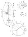
- FIG. 1is a side view, partially in section, of the illuminated directional laser probe of the invention.
- FIG. 2is an enlarged partial view of a portion of the probe shown circled in FIG. 1 .
- FIG. 3is an enlarged partial view of a portion of the probe shown circled in FIG. 1 .
- FIG. 4is an end elevation view of the probe shown in FIG. 1 .
- FIG. 5is a plan view of the optic fibers of the probe removed from the probe.
- FIG. 6is a side elevation view of the optic fibers shown in FIG. 5 .
- FIG. 7is an end elevation view of the fibers shown in FIGS. 5 and 6 .
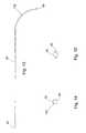
- FIG. 8is a side elevation view, partially in section, of a further embodiment of the illuminated directional laser probe.
- FIG. 9is an enlarged partial view of a portion of the probe shown circled in FIG. 8 .
- FIG. 10is an enlarged partial view of a portion of the probe shown circled in FIG. 8 .
- FIG. 11is an end view of the optic fibers of the probe of FIG. 8 .
- FIG. 12is an end elevation view of the probe of FIG. 8 .
- FIG. 13is a side elevation view of a tube that connects the optic fibers of the probe of FIG. 8 .
- FIG. 14is an end elevation view of the proximal end of the tube shown in FIG. 13 .
- FIG. 15is an end elevation view of the distal end of the tube shown in FIG. 13 .
- the microsurgical illuminated directional laser probe of the inventionis an improvement over microsurgical instruments used in ophthalmic surgery such as those disclosed in the U.S. Pat. No. 6,572,608 titled “Directional Laser Probe,” and U.S. Pat. No. 6,984,230 titled “Directional Laser Probe,” both of which are incorporated herein by reference.
- the illuminated directional laser probe 10 of the inventionhas much of the same basic construction as the probes described in the two above-referenced patents, and therefore the common structural features of the probes will not be described in detail herein.
- the illuminated directional laser probe 10 of the inventionis basically comprised of a handle 12 that has opposite proximal 14 and distal 16 ends.
- An interior bore 18passes entirely through the handle.
- a cavity 22is formed in a side of the handle and is positioned adjacent the handle distal end 16 .
- the cavity 22communicates with the handle interior bore 18 .
- a rigid tubular tip 24projects from the handle distal end 16 .
- the tip 24is preferably constructed of surgical steel and has the dimensions of a syringe needle.
- the tip 24has a straight length that extends between a proximal end 26 of the tip and a distal end 28 of the tip.
- the tip proximal end 24is positioned in the handle cavity 22 and the tip distal end 24 is spaced outwardly from the handle distal end 16 .
- An interior bore 34extends entirely through the tip 24 and communicates with the handle interior bore 18 .
- the tip 24is mounted in the handle bore 18 for sliding reciprocating movement of the tip 24 relative to the handle 12 .
- a finger actuator 34is mounted in the handle cavity 22 for sliding reciprocating movement.
- the finger actuator 34is mounted for forward movement in the cavity 22 toward the handle distal end 16 , and for the opposite rearward movement in the cavity 22 toward the handle proximal end 14 .
- the finger actuator 34is connected to the tip proximal end 26 by a sleeve 36 that surrounds the tip proximal end 26 and by a set screw 38 that is screw threaded in the interior of the actuator 34 .
- movement of the finger actuator in the rearward direction through the cavity 22causes the tip 24 to slide through the handle bore 18 with the tip distal end 28 moving toward the handle distal end 16 .
- Movement of the finger actuator in the forward direction through the handle cavity 22causes the tip 24 to move relative to the handle 12 with the tip distal end 28 moving away from the handle distal end 16 .
- An illumination optic fiber 42extends through the handle bore 18 and through the tip bore 32 .
- the illumination optic fiber 42has an elongate length that extends between a proximal end 44 of the fiber and an opposite distal end 46 of the fiber.
- the illumination optic fiber proximal end 44is connected to an illumination connector 48 that is adapted to be connected to a light source that selectively supplies illumination light to the fiber proximal end 44 .
- Connectors of this typeare known in the art.
- the length of the illumination optic fiber 42extends from its proximal end 44 through the handle interior bore 18 and through the tip interior bore 32 to the distal end 46 of the optic fiber positioned adjacent the distal end 28 of the tip. As in other optic fiber microsurgical instruments, a portion of the protective cladding of the illumination optic fiber 42 is removed adjacent the fiber distal end 46 .
- a laser optic fiber 54also extends through the handle 12 and the tip 24 side by side with the illumination optic fiber 42 .
- the laser optic fiber 54also has an elongate length that extends between a proximal end 56 and a distal end 58 of the fiber.
- a laser light source connector 62is connected to the proximal end 56 of the laser optic fiber 54 .
- the laser light source connector 62is connectable to a separate source of laser light that is transmitted through the laser optic fiber 54 from the fiber proximal end 56 to the fiber distal end 58 .
- Laser light source connectors 62 of the type used with the probe 10 of the inventionare known in the art.
- the distal end 58 of the laser optic fiber 54is shown extending slightly beyond the distal end 46 of the illumination optic fiber 42 . This is to allow the illumination light projected from the illumination optic fiber distal end 46 to illuminate an area of the surgical site being accessed by laser light transmitted from the laser optic fiber distal end 58 .
- the illumination optic fiber distal end 46 and the laser optic fiber distal end 58can be positioned side by side.
- a separate electrical connector 60electrically communicates with the laser source connector 62 .
- the electrical connector 60is not needed for the operation of the illuminated directional laser probe 10 , and therefore is not described further.
- a first resilient tube 64 of resilient materialis mounted on and contains at least a portion of the illumination optic fiber 42 adjacent the fiber distal end 46 .
- the first tube 64has a length that extends from a distal end 66 of the tube positioned adjacent the illumination optic fiber distal end 46 , to an opposite proximal end 68 of the tube that is positioned in the handle 12 .
- the length of the first tube 64extends through the tip bore 32 , the handle bore 18 , and the handle cavity 22 .
- the first tube proximal end 68is secured stationary to the handle 12 by a set screw 72 that is screw threaded in the handle and engages against the first tube at its proximal end 68 .
- the illumination optic fiber distal end 46is secured to the first tube 64 by adhesives or other equivalent means, and thereby the illumination optic fiber 42 is held stationary relative to the handle 12 and to the tip 24 .
- a second tube of resilient material 74is mounted on and contains at least a portion of the laser optic fiber 54 adjacent the laser optic fiber distal end 58 .
- the second tube 74has a length that extends between a distal end 76 of the second tube positioned adjacent the laser optic fiber distal end 58 , to a proximal end 78 of the second tube that is positioned in the handle 12 .
- the length of the second tube 74extends from the distal end 76 of the second tube, through the tip bore 32 , the handle bore 18 , and through the handle cavity 22 .
- the second tube 74is held stationary relative to the handle 12 and the tip 24 by the same set screw 72 that holds the first tube 64 .
- the exterior dimensions of the first tube 64 and the second tube 74 and the interior dimension of the tip bore 32allow the tip 24 to slide easily over the exteriors of the two tubes 64 , 74 as the finger actuator 34 is moved forwardly and rearwardly through the handle cavity 22 .
- At least one of the first tube 64 and second tube 74 , and possibly both of the tubesare constructed of a resilient shape memory material, for example the metal nitinol.
- the tube or tubes 64 , 74are formed in a bent or curved configuration adjacent their distal ends 66 , 76 .
- the resiliency of the material of the tubes 64 , 74allows the tubes to be straightened when a straightening force is exerted on the tubes, and then return to their bent or curved configurations when the straightening force is removed.
- FIG. 1 , 3 , and 4show the curved configurations of the first tube 64 and second tube 74 with portions of the tubes adjacent their respective distal ends 66 , 76 projecting from the distal end 28 of the tip 24 .
- the curved configurations of the tubes 64 , 74also bend portions of the illumination optic fiber 74 and the laser optic fiber 54 in curved configurations adjacent the respective distal ends 46 , 58 of the fibers.
- the illumination optic fiber 42 and the laser optic fiber 54are connected together adjacent their respective distal ends 46 , 58 .
- the illumination optic fiber 42 and the laser optic fiber 54are held together by a plurality of spot welds or brazing material 82 that connect the first tube 64 to the second tube 74 .
- the spacial arrangement of the spot welds 82 along the length of the first tube 64 and second tube 74connects the first and second tubes 64 , 74 side by side, and prevents relative movement between the tubes.
- Thisalso connects the illumination optic fiber 42 and the laser optic fiber 54 side by side adjacent their respective distal ends 46 , 58 , and prevents relative movement between the two fibers.
- the spacial arrangement of the spot welds 82 along the lengths of the two tubes 64 , 74allows the two tubes to resiliently bend between straight configurations and their curved configurations without breaking the connection between the two tubes provided by the spot welds 82 .
- Movement of the finger actuator 34 in the forward direction through the handle cavity 22causes the tip 24 to be extended from the handle distal end 16 .
- Thiscauses the first tube 64 containing the illumination optic fiber 42 and the second tube 74 containing the laser optic fiber 54 to be retracted into the tip 24 at the tip distal end 28 .
- the rigid tip 24straightens the curved or bent configurations of the two tubes. This causes the illumination optic fiber 42 and the laser optic fiber 54 to be gradually straightened as the two fibers are drawn back into the interior bore 32 of the rigid tip 24 .
- the spot welds 82can be replaced by a plurality of spots of adhesive, or by an adhesive extending along portions of the first tube 64 and second tube 74 lengths.
- the spot welds 82can be replaced by a plurality of bands connecting the first tube 64 to the second tube 74 , or a single elongate tubular band that connects the two tubes.
- FIGS. 8-15A second embodiment of the illuminated directional laser probe is shown in FIGS. 8-15 .
- the second embodiment of the probe 90employs many of the same component parts of the previously described embodiment of the probe 10 .
- the common partsare identified in FIGS. 8-15 with the same reference numbers employed in identifying the earlier described probe 10 , with the reference numbers being followed by a prime (′). Because the same component parts of the two probes 10 , 90 have been described previously, they will not be described again in describing the construction of the second embodiment of the probe 9 shown in FIGS. 8-15 .
- the primary difference between the probe 90 shown in FIGS. 8-15 and the previously described probe 10is that the first tube 64 and second tube 74 are absent from the second embodiment of the probe 90 . Instead, a single tube 92 surrounds and contains portions of the illumination optic fiber 42 ′ and the laser optic fiber 54 ′ adjacent the respective distal ends 46 ′, 58 ′ of the two fibers.
- the single tube 92has a length with opposite proximal 94 and distal 96 ends.
- the single tube 92is constructed of a resilient shape memory material, such as nitinol.
- the exterior dimension of the single tube 92is just large enough to extend around and connect the illumination optic fiber 42 ′ and the laser optic fiber 54 ′ side by side, and still slide through the interior bore 32 ′ of the tip 24 ′.
- the single tube 92has a bent or curved configuration adjacent the tube distal end 96 .
- the curved configuration of the single tube 94holds portions of the illumination optic fiber 42 ′ and the laser optic fiber 54 ′ in a bent or curved configuration adjacent the distal ends 46 ′, 58 ′ of the respective fibers.
- the resiliency of the material of the single tube 92allows the curved portion of the tube to be straightened by the rigid tip 24 ′, and then to resume the curved configuration when the curved portion is extended out of the tip 24 ′.
- FIGS. 14-15show the single tube 92 removed from the probe 90 , with the illumination optic fiber 42 ′ and the laser optic fiber 54 ′ removed from the tube.
- the single tube 92has a generally oblong interior bore 98 adjacent the tube distal end 96 .
- the bore 98is dimensioned for containing and connecting the illumination optic fiber 42 ′ and the laser optic fiber 74 ′ adjacent their distal ends.
- an elongate notch 102is formed in the side of the tube.
- the elongate notch 102removes substantially half of the width or half of the side wall of the single tube 92 .
- the notch 102extends from adjacent the single tube distal end 96 , along the entire length of the single tube 92 to the tube proximal end 94 .
- the notch 102increases the flexibility of the single tube 92 and allows the single tube to bend in its curved configuration shown in FIG. 10 .
- the elongate notch 102forms a trough in the interior of the single tube 92 that contains a majority of the length of the illumination optic fiber 42 ′ and the laser optic fiber 54 ′.
- the illumination optic fiber 42 ′ and the laser optic fiber 54 ′are connected to the single tube 92 by an adhesive 104 applied in the interior of the single tube 92 .
- the flexibility of the adhesive 104 and the elongate notch 102allow the illumination optic fiber 42 ′ and the laser optic fiber 54 ′ to flex relative to the single tube 92 as the single tube 92 and the illumination optic fiber 42 ′ and laser optic fiber 54 ′ are moved through their bent or curved configurations shown in FIG. 10 .
- the elongate notch 102is positioned on a side of the single tube 92 that is opposite the concave surface of the tube 92 formed when the tube is in the bent or curved configuration, as shown in FIG. 10 .
- This positioning of the elongate notch 102 relative to the concave surface of the bent or curved single tube 92also permits the connection between the tube 92 and the illumination optic fiber 42 ′ and laser optic fiber 54 ′ to flex as they are moved through their curved configurations, and prevents the illumination optic fiber 42 ′ and/or laser optic fiber 54 ′ from breaking free of the single tube 92 as the tube is moved through the curved configuration.
- the length of the single tube 92extends from the tube distal end 96 through the tip interior bore 32 ′, the handle cavity 22 ′, and the handle interior bore 18 ′ to the tube proximal end 94 .
- the tube proximal end 94is secured stationary to the illumination optic fiber 42 ′ and the laser optic fiber 54 ′, and to the handle 12 ′ by a set screw 106 that is screw threaded into the handle 12 ′ and engages against the side of the single tube 92 adjacent the tube proximal end 94 .
- the single tube 92 and the illumination optic fiber 42 ′ and laser optic fiber 54 ′are held stationary relative to the handle 12 ′ and the tip 24 ′.
- the bent portions of the first tube 64 , second tube 74 , and single tube 92are replaced by a length of wire having shape memory properties.
- the wireis secured to the illumination optic fiber and the laser optic fiber, and is provided with a curved portion that holds the two fibers in a curved configuration when the fibers and the curved portion of the wire are extended from the probe tip.
- At least one, or possibly both of the illumination optic fiber and laser optic fiberare constructed of a material that has shape memory properties.
- the fiber or fibers having the shape memory propertiesare formed in the curved or bent configuration and are held together by spots of adhesive or other equivalent means.
- the shape memory property of the fiber or fiberscauses both the illumination optic fiber and laser optic fiber to gradually bend through a curved or bent configuration as the fiber distal ends are extended from the distal end of the tip by movement of the finger actuator toward the rearward position on the handle.
- the illumination optic fiber and laser optic fiberare straightened by movement of the finger actuator toward the forward position on the handle, which causes the tip distal end to be extended over the curved portions of the two fibers, straightening the two fibers.
- the finger actuatoris connected to the illumination optic fiber and laser optic fiber and causes movement of the two fibers relative to the handle 12 and the tip 24 .
- the tip 24is secured stationary relative to the handle 12 . Movement of the finger actuator in the forward direction causes distal end portions of the illumination optic fiber and laser optic fiber to be extended from the tip distal end, causing the two fibers to move to their bent or curved configurations. Movement of the finger actuator in the rearward direction moves the two fibers back into the interior of the tip, causing straightening of the curved portions of the fibers.
- All of the embodiments of the illuminated directional laser probe of the invention described aboveenable supplying both illumination light and laser light to a surgical site in the interior of an eye through only a single incision in the eye.
- the probes of the inventionalso provide the ability to direct the illumination light and laser light simultaneously to the interior of the eye, enabling accessing a surgical site on an anterior portion or forward portion of the eye interior.
Landscapes
- Health & Medical Sciences (AREA)
- Life Sciences & Earth Sciences (AREA)
- Surgery (AREA)
- Physics & Mathematics (AREA)
- Optics & Photonics (AREA)
- Animal Behavior & Ethology (AREA)
- Engineering & Computer Science (AREA)
- Biomedical Technology (AREA)
- Heart & Thoracic Surgery (AREA)
- Nuclear Medicine, Radiotherapy & Molecular Imaging (AREA)
- Veterinary Medicine (AREA)
- Public Health (AREA)
- General Health & Medical Sciences (AREA)
- Ophthalmology & Optometry (AREA)
- Electromagnetism (AREA)
- Otolaryngology (AREA)
- Medical Informatics (AREA)
- Molecular Biology (AREA)
- Vascular Medicine (AREA)
- Laser Surgery Devices (AREA)
- Radiation-Therapy Devices (AREA)
Abstract
Description
Claims (26)
Priority Applications (1)
| Application Number | Priority Date | Filing Date | Title |
|---|---|---|---|
| US12/063,512US8075553B2 (en) | 2005-08-11 | 2006-08-11 | Illuminated directional laser probe |
Applications Claiming Priority (3)
| Application Number | Priority Date | Filing Date | Title |
|---|---|---|---|
| US70747505P | 2005-08-11 | 2005-08-11 | |
| US12/063,512US8075553B2 (en) | 2005-08-11 | 2006-08-11 | Illuminated directional laser probe |
| PCT/US2006/031348WO2007021914A2 (en) | 2005-08-11 | 2006-08-11 | Illuminated directional laser probe |
Publications (2)
| Publication Number | Publication Date |
|---|---|
| US20080287938A1 US20080287938A1 (en) | 2008-11-20 |
| US8075553B2true US8075553B2 (en) | 2011-12-13 |
Family
ID=37758192
Family Applications (1)
| Application Number | Title | Priority Date | Filing Date |
|---|---|---|---|
| US12/063,512Active2029-01-02US8075553B2 (en) | 2005-08-11 | 2006-08-11 | Illuminated directional laser probe |
Country Status (2)
| Country | Link |
|---|---|
| US (1) | US8075553B2 (en) |
| WO (1) | WO2007021914A2 (en) |
Cited By (40)
| Publication number | Priority date | Publication date | Assignee | Title |
|---|---|---|---|---|
| US20130071507A1 (en)* | 2011-09-17 | 2013-03-21 | Katalyst Surgical, Llc | Steerable laser probe |
| US8840605B2 (en) | 2011-09-02 | 2014-09-23 | Katalyst Surgical, Llc | Steerable laser probe |
| US8840607B2 (en) | 2011-12-23 | 2014-09-23 | Katalyst Surgical, Llc | Steerable laser probe |
| US8951245B2 (en) | 2012-05-09 | 2015-02-10 | Katalyst Surgical, Llc | Steerable laser probe |
| US8968277B2 (en) | 2011-12-09 | 2015-03-03 | Katalyst Surgical, Llc | Steerable laser probe |
| US9023019B2 (en) | 2012-05-10 | 2015-05-05 | Katalyst Surgical, Llc | Steerable laser probe |
| US9023020B2 (en) | 2012-06-06 | 2015-05-05 | Katalyst Surgical, Llc | Steerable laser probe |
| US9039686B2 (en) | 2012-04-19 | 2015-05-26 | Katalyst Surgical, Llc | Steerable laser probe |
| US9107682B2 (en) | 2011-11-03 | 2015-08-18 | Katalyst Surgical, Llc | Steerable laser probe |
| US9113995B2 (en) | 2012-05-08 | 2015-08-25 | Katalyst Surgical, Llc | Steerable laser probe |
| US9138350B2 (en) | 2011-10-17 | 2015-09-22 | Katalyst Surgical, Llc | Steerable laser probe |
| US9216060B2 (en) | 2012-08-14 | 2015-12-22 | Katalyst Surgical, Llc | Steerable laser probe |
| US9216111B2 (en) | 2012-09-24 | 2015-12-22 | Katalyst Surgical, Llc | Steerable laser probe |
| US9226794B2 (en) | 2012-09-23 | 2016-01-05 | Katalyst Surgical, Llc | Steerable laser probe |
| US9226855B2 (en) | 2012-09-06 | 2016-01-05 | Katalyst Surgical, Llc | Steerable laser probe |
| US9232975B2 (en) | 2012-09-05 | 2016-01-12 | Katalyst Surgical, Llc | Steerable laser probe |
| US9233022B2 (en) | 2012-08-06 | 2016-01-12 | Katalyst Surgical, Llc | Steerable laser probe |
| US20160051335A1 (en)* | 2014-08-25 | 2016-02-25 | Peregrine Surgical Ltd. | Microsurgical instrument |
| US9345542B2 (en) | 2012-09-11 | 2016-05-24 | Katalyst Surgical, Llc | Steerable laser probe |
| US9351875B2 (en) | 2012-09-12 | 2016-05-31 | Katalyst Surgical, Llc | Steerable laser probe |
| US9433530B1 (en) | 2015-04-24 | 2016-09-06 | Katalyst Surgical, Llc | Steerable laser probe and methods of use |
| US9480600B2 (en) | 2012-06-27 | 2016-11-01 | Katalyst Surgical, Llc | Steerable laser probe |
| US9549780B2 (en) | 2012-05-13 | 2017-01-24 | Katalyst Surgical, Llc | Steerable laser probe |
| US9763830B2 (en) | 2012-10-13 | 2017-09-19 | Katalyst Surgical, Llc | Steerable laser probe |
| US9770298B2 (en) | 2012-08-10 | 2017-09-26 | Katalyst Surgical, Llc | Steerable laser probe |
| US9770296B2 (en) | 2012-07-31 | 2017-09-26 | Katalyst Surgical, Llc | Steerable laser probe |
| US9851060B2 (en) | 2013-04-01 | 2017-12-26 | Vinod V. Pathy | Lighting device for attachment to a tool |
| US9877867B2 (en) | 2012-08-01 | 2018-01-30 | Katalyst Surgical, Llc | Steerable laser probe |
| US9931246B2 (en) | 2012-10-17 | 2018-04-03 | Katalyst Surgical, Llc | Steerable laser probe |
| US10039669B2 (en) | 2014-10-24 | 2018-08-07 | Novartis Ag | Internally illuminated surgical probe |
| US10201452B2 (en) | 2013-07-31 | 2019-02-12 | Katalyst Surgical, Inc. | Laser probe with a replaceable optic fiber |
| USD843596S1 (en) | 2014-01-09 | 2019-03-19 | Axiosonic, Llc | Ultrasound applicator |
| US10245182B2 (en) | 2015-11-14 | 2019-04-02 | Katalyst Surgical, Llc | Laser probe with replaceable optic fibers |
| US10307290B2 (en) | 2015-07-13 | 2019-06-04 | Novartis Ag | Vitreous cutter with integrated illumination system |
| US10420460B2 (en) | 2016-09-09 | 2019-09-24 | Katalyst Surgical, Llc | Illumination probe |
| US10646113B2 (en) | 2016-09-09 | 2020-05-12 | Katalyst Surgical, Llc | Illuminated cannula |
| US10709504B2 (en) | 2016-09-19 | 2020-07-14 | Katalyst Surgical, Llc | Curved laser probe with single-use optic fiber |
| USD938095S1 (en) | 2013-04-01 | 2021-12-07 | Pathy Medical, Llc | Lighting device |
| WO2025054396A1 (en)* | 2023-09-08 | 2025-03-13 | D.O.R.C. Dutch Ophthalmic Research Center (International) B.V. | Steerable and adjustable chandelier |
| WO2025180851A1 (en) | 2024-02-28 | 2025-09-04 | Carl Zeiss Meditec Ag | Ophthalmic surgical system with deformable-sheath optical probe and motorized actuator |
Families Citing this family (7)
| Publication number | Priority date | Publication date | Assignee | Title |
|---|---|---|---|---|
| WO2005048817A2 (en)* | 2003-11-13 | 2005-06-02 | Synergetics, Inc. | Illuminated laser probe with adjustble area of illumination |
| SI22604B (en)* | 2007-10-26 | 2017-04-26 | Optotek D.O.O. | Surgical tool for laser based endocanaliculary dacriocistorinostomy |
| EP2473128B2 (en) | 2009-09-04 | 2019-03-13 | Bausch & Lomb Incorporated | Illumination device for use in an ophthalmic surgical apparatus |
| WO2013019859A1 (en) | 2011-08-03 | 2013-02-07 | Alcon Research, Ltd. | Articulating ophthalmic surgical probe |
| US9370447B2 (en)* | 2011-10-10 | 2016-06-21 | Cygnus LP | Probes for use in ophthalmic and vitreoretinal surgery |
| US10064554B2 (en) | 2011-12-14 | 2018-09-04 | The Trustees Of The University Of Pennsylvania | Fiber optic flow and oxygenation monitoring using diffuse correlation and reflectance |
| NL2008455C2 (en)* | 2012-03-09 | 2013-09-10 | D O R C Dutch Ophthalmic Res Ct International B V | EYE-SURGICAL LIGHTING UNIT. |
Citations (33)
| Publication number | Priority date | Publication date | Assignee | Title |
|---|---|---|---|---|
| US4347837A (en) | 1979-09-17 | 1982-09-07 | Olympus Optical Co., Ltd. | Structure for preventing the breakage of end portions of a protective covering for the adjustable bend section of an endoscope |
| US4674497A (en) | 1984-08-15 | 1987-06-23 | Olympus Optical Co., Ltd. | Medical laser device |
| US4744360A (en) | 1986-12-18 | 1988-05-17 | Bath Patricia E | Apparatus for ablating and removing cataract lenses |
| US5156604A (en) | 1990-10-25 | 1992-10-20 | Messerschmitt-Bolkow-Blohm Gmbh | Small probing hook for arthroscopy |
| US5172685A (en) | 1988-05-27 | 1992-12-22 | The University Of Connecticut | Endoscope and video laser camera system therefor |
| US5281214A (en) | 1992-04-21 | 1994-01-25 | Laserscope | Disposable surgical probe having fiber diverter |
| US5300061A (en) | 1991-08-29 | 1994-04-05 | Surgical Technologies, Inc. | Laser delivery probe having a mechanically free floating sheath |
| US5356407A (en)* | 1992-04-30 | 1994-10-18 | Infinitech, Inc. | Ophthalmic surgery probe assembly |
| US5372585A (en) | 1992-04-09 | 1994-12-13 | Tiefenbrun; Jonathan | Instrument and associated method for applying biologically effective composition during laparoscopic operation |
| US5469524A (en) | 1994-05-12 | 1995-11-21 | Indigo Medical, Incorporated | Fiberoptic delivery system and method of use |
| US5512034A (en) | 1992-11-25 | 1996-04-30 | Finn; Miles A. | Surgical instrument including viewing optics and a ball probe |
| US5520222A (en) | 1989-10-13 | 1996-05-28 | Kabushiki Kaisha Machida Seisakusho | Bending device |
| US5603710A (en) | 1993-04-15 | 1997-02-18 | Infinitech, Inc. | Laser delivery system with soft tip |
| US5656011A (en) | 1994-04-28 | 1997-08-12 | Epflex Feinwerktechnik Gmbh | Endoscope tube system |
| US5688264A (en) | 1992-10-19 | 1997-11-18 | The University Of Miami | Laser treatment for retinal detachment |
| US5735792A (en) | 1992-11-25 | 1998-04-07 | Clarus Medical Systems, Inc. | Surgical instrument including viewing optics and an atraumatic probe |
| US5741225A (en) | 1992-08-12 | 1998-04-21 | Rita Medical Systems | Method for treating the prostate |
| US5766164A (en) | 1996-07-03 | 1998-06-16 | Eclipse Surgical Technologies, Inc. | Contiguous, branched transmyocardial revascularization (TMR) channel, method and device |
| US5807242A (en) | 1997-03-24 | 1998-09-15 | Synergetics, Inc. | Microsurgical laser probe with homogeneous laser light field |
| US5855577A (en)* | 1996-09-17 | 1999-01-05 | Eclipse Surgical Technologies, Inc. | Bow shaped catheter |
| US5865831A (en) | 1996-04-17 | 1999-02-02 | Premier Laser Systems, Inc. | Laser surgical procedures for treatment of glaucoma |
| US5957916A (en) | 1994-05-25 | 1999-09-28 | The Trustees Of Columbia University In The City Of New York | Myocardial revascularization through the endocardial surface using a laser |
| US5993072A (en) | 1996-04-17 | 1999-11-30 | The Johns Hopkins University | Adapter assembly for connecting multiple optic fiber illuminated microsurgical instruments to a single light source |
| USRE36473E (en) | 1994-05-12 | 1999-12-28 | Indigo Medical, Inc. | Fiberoptic delivery system and method of use |
| US6015403A (en) | 1996-02-26 | 2000-01-18 | Alcon Laboratories, Inc. | Ophthalmic surgery probe with soft tip |
| US6053911A (en) | 1996-11-08 | 2000-04-25 | Thomas J. Fogarty | Transvascular TMR device and method |
| US6142990A (en) | 1997-02-15 | 2000-11-07 | Heidelberg Engineering Optische Messsysteme Gmbh | Medical apparatus, especially for reducing intraocular pressure |
| US6428553B1 (en) | 2000-03-08 | 2002-08-06 | Nuvue Technologies, Inc. | Illuminated ophthalmic membrane pick assembly |
| US6572608B1 (en) | 1999-04-08 | 2003-06-03 | Eric T. Lee | Directional laser probe |
| US6575989B1 (en) | 1999-09-13 | 2003-06-10 | Synergetics, Inc. | Adjustable stiffness membrane scraper |
| US20050154379A1 (en) | 2003-01-31 | 2005-07-14 | Innovatech Surgical, Inc. | Adjustable laser probe for use in vitreoretinal surgery |
| US6984230B2 (en)* | 2000-04-07 | 2006-01-10 | Synergetics, Inc. | Directional laser probe |
| US7141048B1 (en) | 2002-10-17 | 2006-11-28 | Alcon, Inc. | Vitreoretinal instrument |
- 2006
- 2006-08-11WOPCT/US2006/031348patent/WO2007021914A2/enactiveApplication Filing
- 2006-08-11USUS12/063,512patent/US8075553B2/enactiveActive
Patent Citations (34)
| Publication number | Priority date | Publication date | Assignee | Title |
|---|---|---|---|---|
| US4347837A (en) | 1979-09-17 | 1982-09-07 | Olympus Optical Co., Ltd. | Structure for preventing the breakage of end portions of a protective covering for the adjustable bend section of an endoscope |
| US4674497A (en) | 1984-08-15 | 1987-06-23 | Olympus Optical Co., Ltd. | Medical laser device |
| US4744360A (en) | 1986-12-18 | 1988-05-17 | Bath Patricia E | Apparatus for ablating and removing cataract lenses |
| US5172685A (en) | 1988-05-27 | 1992-12-22 | The University Of Connecticut | Endoscope and video laser camera system therefor |
| US5520222A (en) | 1989-10-13 | 1996-05-28 | Kabushiki Kaisha Machida Seisakusho | Bending device |
| US5156604A (en) | 1990-10-25 | 1992-10-20 | Messerschmitt-Bolkow-Blohm Gmbh | Small probing hook for arthroscopy |
| US5300061A (en) | 1991-08-29 | 1994-04-05 | Surgical Technologies, Inc. | Laser delivery probe having a mechanically free floating sheath |
| US5372585A (en) | 1992-04-09 | 1994-12-13 | Tiefenbrun; Jonathan | Instrument and associated method for applying biologically effective composition during laparoscopic operation |
| US5281214A (en) | 1992-04-21 | 1994-01-25 | Laserscope | Disposable surgical probe having fiber diverter |
| US5356407A (en)* | 1992-04-30 | 1994-10-18 | Infinitech, Inc. | Ophthalmic surgery probe assembly |
| US5741225A (en) | 1992-08-12 | 1998-04-21 | Rita Medical Systems | Method for treating the prostate |
| US5688264A (en) | 1992-10-19 | 1997-11-18 | The University Of Miami | Laser treatment for retinal detachment |
| US5512034A (en) | 1992-11-25 | 1996-04-30 | Finn; Miles A. | Surgical instrument including viewing optics and a ball probe |
| US5735792A (en) | 1992-11-25 | 1998-04-07 | Clarus Medical Systems, Inc. | Surgical instrument including viewing optics and an atraumatic probe |
| US5603710A (en) | 1993-04-15 | 1997-02-18 | Infinitech, Inc. | Laser delivery system with soft tip |
| US5656011A (en) | 1994-04-28 | 1997-08-12 | Epflex Feinwerktechnik Gmbh | Endoscope tube system |
| US5469524A (en) | 1994-05-12 | 1995-11-21 | Indigo Medical, Incorporated | Fiberoptic delivery system and method of use |
| USRE36473E (en) | 1994-05-12 | 1999-12-28 | Indigo Medical, Inc. | Fiberoptic delivery system and method of use |
| US5957916A (en) | 1994-05-25 | 1999-09-28 | The Trustees Of Columbia University In The City Of New York | Myocardial revascularization through the endocardial surface using a laser |
| US6015403A (en) | 1996-02-26 | 2000-01-18 | Alcon Laboratories, Inc. | Ophthalmic surgery probe with soft tip |
| US5865831A (en) | 1996-04-17 | 1999-02-02 | Premier Laser Systems, Inc. | Laser surgical procedures for treatment of glaucoma |
| US5993072A (en) | 1996-04-17 | 1999-11-30 | The Johns Hopkins University | Adapter assembly for connecting multiple optic fiber illuminated microsurgical instruments to a single light source |
| US5766164A (en) | 1996-07-03 | 1998-06-16 | Eclipse Surgical Technologies, Inc. | Contiguous, branched transmyocardial revascularization (TMR) channel, method and device |
| US5855577A (en)* | 1996-09-17 | 1999-01-05 | Eclipse Surgical Technologies, Inc. | Bow shaped catheter |
| US6053911A (en) | 1996-11-08 | 2000-04-25 | Thomas J. Fogarty | Transvascular TMR device and method |
| US6142990A (en) | 1997-02-15 | 2000-11-07 | Heidelberg Engineering Optische Messsysteme Gmbh | Medical apparatus, especially for reducing intraocular pressure |
| US5807242A (en) | 1997-03-24 | 1998-09-15 | Synergetics, Inc. | Microsurgical laser probe with homogeneous laser light field |
| US6572608B1 (en) | 1999-04-08 | 2003-06-03 | Eric T. Lee | Directional laser probe |
| US6575989B1 (en) | 1999-09-13 | 2003-06-10 | Synergetics, Inc. | Adjustable stiffness membrane scraper |
| US6428553B1 (en) | 2000-03-08 | 2002-08-06 | Nuvue Technologies, Inc. | Illuminated ophthalmic membrane pick assembly |
| US6984230B2 (en)* | 2000-04-07 | 2006-01-10 | Synergetics, Inc. | Directional laser probe |
| US7473249B2 (en)* | 2000-04-07 | 2009-01-06 | Synergetics, Inc. | Directional laser probe |
| US7141048B1 (en) | 2002-10-17 | 2006-11-28 | Alcon, Inc. | Vitreoretinal instrument |
| US20050154379A1 (en) | 2003-01-31 | 2005-07-14 | Innovatech Surgical, Inc. | Adjustable laser probe for use in vitreoretinal surgery |
Cited By (113)
| Publication number | Priority date | Publication date | Assignee | Title |
|---|---|---|---|---|
| US8840605B2 (en) | 2011-09-02 | 2014-09-23 | Katalyst Surgical, Llc | Steerable laser probe |
| US9757277B2 (en) | 2011-09-02 | 2017-09-12 | Katalyst Surgical, Llc | Steerable laser probe |
| US10695221B2 (en) | 2011-09-02 | 2020-06-30 | Katalyst Surgical, Llc | Steerable laser probe |
| US20150282989A1 (en)* | 2011-09-17 | 2015-10-08 | Katalyst Surgical, Llc | Steerable laser probe |
| US20130071507A1 (en)* | 2011-09-17 | 2013-03-21 | Katalyst Surgical, Llc | Steerable laser probe |
| US9237966B2 (en) | 2011-09-17 | 2016-01-19 | Katalyst Surgical, Llc | Steerable laser probe |
| US9433531B1 (en) | 2011-09-17 | 2016-09-06 | Katalyst Surgical, Llc | Steerable laser probe |
| US9782294B2 (en) | 2011-09-17 | 2017-10-10 | Katalyst Surgical, Llc | Steerable laser probe |
| US9326892B2 (en)* | 2011-09-17 | 2016-05-03 | Katalyst Surgical, Llc | Steerable laser probe |
| US9089399B2 (en)* | 2011-09-17 | 2015-07-28 | Katalyst Surgical, Llc | Steerable laser probe |
| US10492952B2 (en) | 2011-10-17 | 2019-12-03 | Katalyst Surgical, Llc | Steerable laser probe |
| US9782295B2 (en) | 2011-10-17 | 2017-10-10 | Katalyst Surgical, Llc | Steerable laser probe |
| US10098786B2 (en) | 2011-10-17 | 2018-10-16 | Katalyst Surgical, Llc | Steerable laser probe |
| US9138350B2 (en) | 2011-10-17 | 2015-09-22 | Katalyst Surgical, Llc | Steerable laser probe |
| US9474650B2 (en) | 2011-10-17 | 2016-10-25 | Katalyst Surgical, Llc | Steerable laser probe |
| US9554942B1 (en) | 2011-11-03 | 2017-01-31 | Katalyst Surgical, Llc | Steerable laser probe |
| US9889044B1 (en) | 2011-11-03 | 2018-02-13 | Katalyst Surgical, Llc | Steerable laser probe |
| US10709609B2 (en) | 2011-11-03 | 2020-07-14 | Katalyst Surgical, Llc | Steerable laser probe |
| US9107682B2 (en) | 2011-11-03 | 2015-08-18 | Katalyst Surgical, Llc | Steerable laser probe |
| US9717630B1 (en) | 2011-11-03 | 2017-08-01 | Katalyst Surgical, Llc | Steerable laser probe |
| US9398980B2 (en) | 2011-11-03 | 2016-07-26 | Katalyst Surgical, Llc | Steerable laser probe |
| US9872731B2 (en) | 2011-12-09 | 2018-01-23 | Katalyst Surgical, Llc | Steerable laser probe |
| US9408666B1 (en) | 2011-12-09 | 2016-08-09 | Katalyst Surgical, Llc | Steerable laser probe |
| US8968277B2 (en) | 2011-12-09 | 2015-03-03 | Katalyst Surgical, Llc | Steerable laser probe |
| US9132035B2 (en) | 2011-12-09 | 2015-09-15 | Katalyst Surgical, Llc | Steerable laser probe |
| US10188373B2 (en) | 2011-12-23 | 2019-01-29 | Katalyst Surgical, Llc | Steerable laser probe |
| US8840607B2 (en) | 2011-12-23 | 2014-09-23 | Katalyst Surgical, Llc | Steerable laser probe |
| US9693906B2 (en) | 2011-12-23 | 2017-07-04 | Katalyst Surgical, Llc | Steerable laser probe |
| US9855026B2 (en) | 2011-12-23 | 2018-01-02 | Katalyst Surgical, Llc | Steerable laser probe |
| US9119702B2 (en) | 2011-12-23 | 2015-09-01 | Katalyst Surgical, Llc | Steerable laser probe |
| US9265657B2 (en) | 2012-04-19 | 2016-02-23 | Katalyst Surgical, Llc | Steerable laser probe |
| US9039686B2 (en) | 2012-04-19 | 2015-05-26 | Katalyst Surgical, Llc | Steerable laser probe |
| US10052232B2 (en) | 2012-04-19 | 2018-08-21 | Katalyst Surgical, Llc | Steerable laser probe |
| US9572714B2 (en) | 2012-05-08 | 2017-02-21 | Katalyst Surgical, Llc | Steerable laser probe |
| US10376315B2 (en) | 2012-05-08 | 2019-08-13 | Katalyst Surgical, Llc | Steerable laser probe |
| US9775745B2 (en) | 2012-05-08 | 2017-10-03 | Katalyst Surgical, Llc | Steerable laser probe |
| US9113995B2 (en) | 2012-05-08 | 2015-08-25 | Katalyst Surgical, Llc | Steerable laser probe |
| US9925089B2 (en) | 2012-05-09 | 2018-03-27 | Katalyst Surgical, Llc | Steerable laser probe |
| US9433529B2 (en) | 2012-05-09 | 2016-09-06 | Katalyst Surgical, Llc | Steerable laser probe |
| US10245183B2 (en) | 2012-05-09 | 2019-04-02 | Katalyst Surgical, Llc | Steerable laser probe |
| US8951245B2 (en) | 2012-05-09 | 2015-02-10 | Katalyst Surgical, Llc | Steerable laser probe |
| US10052230B2 (en) | 2012-05-10 | 2018-08-21 | Katalyst Surgical, Llc | Steerable laser probe |
| US9226854B2 (en) | 2012-05-10 | 2016-01-05 | Katalyst Surgical, Llc | Steerable laser probe |
| US9023019B2 (en) | 2012-05-10 | 2015-05-05 | Katalyst Surgical, Llc | Steerable laser probe |
| US9351876B1 (en) | 2012-05-10 | 2016-05-31 | Katalyst Surgical, Llc | Steerable laser probe |
| US11234766B2 (en) | 2012-05-13 | 2022-02-01 | Gregg D Scheller | Steerable laser probe |
| US9549780B2 (en) | 2012-05-13 | 2017-01-24 | Katalyst Surgical, Llc | Steerable laser probe |
| US10307208B2 (en) | 2012-05-13 | 2019-06-04 | Katalyst Surgical, Llc | Steerable laser probe |
| US9480602B2 (en) | 2012-06-06 | 2016-11-01 | Katalyst Surgical, Llc | Steerable laser probe |
| US9023020B2 (en) | 2012-06-06 | 2015-05-05 | Katalyst Surgical, Llc | Steerable laser probe |
| US9925090B2 (en) | 2012-06-06 | 2018-03-27 | Katalyst Surgical, Llc | Steerable laser probe |
| US9480600B2 (en) | 2012-06-27 | 2016-11-01 | Katalyst Surgical, Llc | Steerable laser probe |
| US10070923B2 (en) | 2012-07-31 | 2018-09-11 | Katalyst Surgical, Llc | Steerable laser probe |
| US9770296B2 (en) | 2012-07-31 | 2017-09-26 | Katalyst Surgical, Llc | Steerable laser probe |
| US9877867B2 (en) | 2012-08-01 | 2018-01-30 | Katalyst Surgical, Llc | Steerable laser probe |
| US9233022B2 (en) | 2012-08-06 | 2016-01-12 | Katalyst Surgical, Llc | Steerable laser probe |
| US10004640B2 (en) | 2012-08-06 | 2018-06-26 | Katalyst Surgical, Llc | Steerable laser probe |
| US9770298B2 (en) | 2012-08-10 | 2017-09-26 | Katalyst Surgical, Llc | Steerable laser probe |
| US9888965B2 (en) | 2012-08-10 | 2018-02-13 | Katalyst Surgical, Llc | Steerable laser probe |
| US11045254B2 (en) | 2012-08-10 | 2021-06-29 | Katalyst Surgical, Llc | Steerable laser probe |
| US10357313B2 (en) | 2012-08-10 | 2019-07-23 | Katalyst Surgical, Llc | Steerable laser probe |
| US9216060B2 (en) | 2012-08-14 | 2015-12-22 | Katalyst Surgical, Llc | Steerable laser probe |
| US10335235B2 (en) | 2012-08-14 | 2019-07-02 | Katalyst Surgical, Llc | Steerable laser probe |
| US9849035B2 (en) | 2012-08-14 | 2017-12-26 | Katalyst Surgical, Llc | Steerable laser probe |
| US9681918B2 (en) | 2012-08-14 | 2017-06-20 | Katalyst Surgical, Llc | Steerable laser probe |
| US9770364B2 (en) | 2012-09-05 | 2017-09-26 | Katalyst Surgical, Llc | Steerable laser probe |
| US9232975B2 (en) | 2012-09-05 | 2016-01-12 | Katalyst Surgical, Llc | Steerable laser probe |
| US10076444B2 (en) | 2012-09-05 | 2018-09-18 | Katalyst Surgical, Llc | Steerable laser probe |
| US9549853B2 (en) | 2012-09-05 | 2017-01-24 | Katalyst Surgical, Llc | Steerable laser probe |
| US9226855B2 (en) | 2012-09-06 | 2016-01-05 | Katalyst Surgical, Llc | Steerable laser probe |
| US9901484B1 (en) | 2012-09-06 | 2018-02-27 | Katalyst Surgical, Llc | Steerable laser probe |
| US9775744B2 (en) | 2012-09-06 | 2017-10-03 | Katalyst Surgical, Llc | Steerable laser probe |
| US10792187B2 (en) | 2012-09-06 | 2020-10-06 | Katalyst Surgical, Llc | Steerable laser probe |
| US9539142B2 (en) | 2012-09-06 | 2017-01-10 | Katalyst Surgical, Llc | Steerable laser probe |
| US9345542B2 (en) | 2012-09-11 | 2016-05-24 | Katalyst Surgical, Llc | Steerable laser probe |
| US9770363B2 (en) | 2012-09-11 | 2017-09-26 | Katalyst Surgical, Llc | Steerable laser probe |
| US9681986B2 (en) | 2012-09-12 | 2017-06-20 | Katalyst Surgical, Llc | Steerable laser probe |
| US9351875B2 (en) | 2012-09-12 | 2016-05-31 | Katalyst Surgical, Llc | Steerable laser probe |
| US10052231B2 (en) | 2012-09-12 | 2018-08-21 | Katalyst Surgical, Llc | Steerable laser probe |
| US9795510B2 (en) | 2012-09-23 | 2017-10-24 | Katalyst Surgical, Llc | Steerable laser probe |
| US9226794B2 (en) | 2012-09-23 | 2016-01-05 | Katalyst Surgical, Llc | Steerable laser probe |
| US9364371B2 (en) | 2012-09-23 | 2016-06-14 | Katalyst Surgical, Llc | Steerable laser probe |
| US10064755B2 (en) | 2012-09-23 | 2018-09-04 | Katalyst Surgical, Llc | Steerable laser probe |
| US9216111B2 (en) | 2012-09-24 | 2015-12-22 | Katalyst Surgical, Llc | Steerable laser probe |
| US10064754B2 (en) | 2012-09-24 | 2018-09-04 | Katalyst Surgical, Llc | Steerable laser probe |
| US9375350B2 (en) | 2012-09-24 | 2016-06-28 | Katalyst Surgical, Llc | Steerable laser probe |
| US9375351B2 (en) | 2012-09-24 | 2016-06-28 | Katalyst Surgical, Llc | Steerable laser probe |
| US9320649B2 (en) | 2012-09-24 | 2016-04-26 | Katalyst Surgical, Llc | Steerable laser probe |
| US9757278B2 (en) | 2012-09-24 | 2017-09-12 | Katalyst Surgical, Llc | Steerable laser probe |
| US9445945B2 (en) | 2012-09-24 | 2016-09-20 | Katalyst Surgical, Llc | Steerable laser probe |
| US10695222B2 (en) | 2012-10-13 | 2020-06-30 | Katalyst Surgical, Llc | Steerable laser probe |
| US9763830B2 (en) | 2012-10-13 | 2017-09-19 | Katalyst Surgical, Llc | Steerable laser probe |
| US9931246B2 (en) | 2012-10-17 | 2018-04-03 | Katalyst Surgical, Llc | Steerable laser probe |
| USD991542S1 (en) | 2013-04-01 | 2023-07-04 | Pathy Medical, Llc | Lighting device |
| US11519569B2 (en) | 2013-04-01 | 2022-12-06 | Pathy Medical, Llc | Lighting device with cavity for removably attaching to a tool |
| US9851060B2 (en) | 2013-04-01 | 2017-12-26 | Vinod V. Pathy | Lighting device for attachment to a tool |
| USD938095S1 (en) | 2013-04-01 | 2021-12-07 | Pathy Medical, Llc | Lighting device |
| US10816147B2 (en) | 2013-04-01 | 2020-10-27 | Pathy Medical, Llc | Lighting device with cavity for removably attaching to a tool |
| US10213341B2 (en) | 2013-07-31 | 2019-02-26 | Katalyst Surgical, Llc | Laser probe with a replaceable optic fiber |
| US10201452B2 (en) | 2013-07-31 | 2019-02-12 | Katalyst Surgical, Inc. | Laser probe with a replaceable optic fiber |
| USD843596S1 (en) | 2014-01-09 | 2019-03-19 | Axiosonic, Llc | Ultrasound applicator |
| US10022200B2 (en)* | 2014-08-25 | 2018-07-17 | Peregrine Surgical, Ltd | Microsurgical instrument |
| US20160051335A1 (en)* | 2014-08-25 | 2016-02-25 | Peregrine Surgical Ltd. | Microsurgical instrument |
| US10039669B2 (en) | 2014-10-24 | 2018-08-07 | Novartis Ag | Internally illuminated surgical probe |
| US9498381B2 (en) | 2015-04-24 | 2016-11-22 | Katalyst Surgical, Llc | Steerable laser probe and methods of use |
| US9433530B1 (en) | 2015-04-24 | 2016-09-06 | Katalyst Surgical, Llc | Steerable laser probe and methods of use |
| US10307290B2 (en) | 2015-07-13 | 2019-06-04 | Novartis Ag | Vitreous cutter with integrated illumination system |
| US10245182B2 (en) | 2015-11-14 | 2019-04-02 | Katalyst Surgical, Llc | Laser probe with replaceable optic fibers |
| US10420460B2 (en) | 2016-09-09 | 2019-09-24 | Katalyst Surgical, Llc | Illumination probe |
| US10646113B2 (en) | 2016-09-09 | 2020-05-12 | Katalyst Surgical, Llc | Illuminated cannula |
| US10709504B2 (en) | 2016-09-19 | 2020-07-14 | Katalyst Surgical, Llc | Curved laser probe with single-use optic fiber |
| WO2025054396A1 (en)* | 2023-09-08 | 2025-03-13 | D.O.R.C. Dutch Ophthalmic Research Center (International) B.V. | Steerable and adjustable chandelier |
| WO2025180851A1 (en) | 2024-02-28 | 2025-09-04 | Carl Zeiss Meditec Ag | Ophthalmic surgical system with deformable-sheath optical probe and motorized actuator |
Also Published As
| Publication number | Publication date |
|---|---|
| US20080287938A1 (en) | 2008-11-20 |
| WO2007021914A3 (en) | 2008-10-09 |
| WO2007021914A2 (en) | 2007-02-22 |
Similar Documents
| Publication | Publication Date | Title |
|---|---|---|
| US8075553B2 (en) | Illuminated directional laser probe | |
| US7766904B2 (en) | Adjustable laser probe for use in vitreoretinal surgery | |
| JP3665742B2 (en) | Directional laser probe | |
| US6984230B2 (en) | Directional laser probe | |
| US6730076B2 (en) | Fiberoptic probe tip | |
| US8834456B2 (en) | Steerable and flexibly curved probes | |
| US7842027B2 (en) | Multi-purpose surgical instrument with integral optical system | |
| US20090221991A1 (en) | Multi-Purpose Surgical Instrument With Removable Component | |
| US4524770A (en) | Endoscope injection needle | |
| JP5997272B2 (en) | Arthroscopic surgery probe | |
| US5916149A (en) | Shielded illumination device for ophthalmic surgery and the like | |
| US20060211918A1 (en) | Surgical instrument with integral optical system | |
| US20090187170A1 (en) | Ophthalmic surgery light transmitting apparatus | |
| US20110125139A1 (en) | Multi-fiber flexible surgical probe | |
| KR20130008556A (en) | Multi-fiber flexible surgical probe | |
| US7060028B2 (en) | Endoilluminator | |
| US20080275435A1 (en) | Illuminated Laser Probe with Multiplied Area of Illumination | |
| JP2007511292A (en) | Illumination laser probe with adjustable illumination area | |
| US20030088257A1 (en) | Directional endo-illuminator |
Legal Events
| Date | Code | Title | Description |
|---|---|---|---|
| AS | Assignment | Owner name:SYNERGETICS, INC., MISSOURI Free format text:ASSIGNMENT OF ASSIGNORS INTEREST;ASSIGNORS:SCHELLER, GREGG D.;AULD, MICHAEL D.;NADOLSKI, TIMOTHY J.;REEL/FRAME:020650/0905;SIGNING DATES FROM 20080225 TO 20080302 Owner name:SYNERGETICS, INC., MISSOURI Free format text:ASSIGNMENT OF ASSIGNORS INTEREST;ASSIGNORS:SCHELLER, GREGG D.;AULD, MICHAEL D.;NADOLSKI, TIMOTHY J.;SIGNING DATES FROM 20080225 TO 20080302;REEL/FRAME:020650/0905 | |
| STCF | Information on status: patent grant | Free format text:PATENTED CASE | |
| AS | Assignment | Owner name:REGIONS BANK, MISSOURI Free format text:SECURITY INTEREST;ASSIGNOR:SYNERGETICS, INC.;REEL/FRAME:034529/0867 Effective date:20141216 | |
| REMI | Maintenance fee reminder mailed | ||
| AS | Assignment | Owner name:SYNERGETICS, INC., MISSOURI Free format text:RELEASE BY SECURED PARTY;ASSIGNOR:REGIONS BANK;REEL/FRAME:036793/0972 Effective date:20151014 | |
| FPAY | Fee payment | Year of fee payment:4 | |
| SULP | Surcharge for late payment | ||
| AS | Assignment | Owner name:BARCLAYS BANK PLC, AS COLLATERAL AGENT, NEW YORK Free format text:SECURITY AGREEMENT;ASSIGNORS:SPROUT PHARMACEUTICALS, INC., AS GRANTOR;UNILENS VISION INC., AS GRANTOR;COMMONWEALTH LABORATORIES, LLC, AS GRANTOR;AND OTHERS;REEL/FRAME:037357/0490 Effective date:20151221 | |
| AS | Assignment | Owner name:THE BANK OF NEW YORK MELLON, AS NOTES COLLATERAL A Free format text:SECURITY INTEREST;ASSIGNORS:BAUSCH HEALTH AMERICAS, INC.;BAUSCH & LOMB INCORPORATED;BAUSCH HEALTH US, LLC;AND OTHERS;REEL/FRAME:048556/0758 Effective date:20190308 Owner name:THE BANK OF NEW YORK MELLON, AS NOTES COLLATERAL AGENT, NEW YORK Free format text:SECURITY INTEREST;ASSIGNORS:BAUSCH HEALTH AMERICAS, INC.;BAUSCH & LOMB INCORPORATED;BAUSCH HEALTH US, LLC;AND OTHERS;REEL/FRAME:048556/0758 Effective date:20190308 | |
| MAFP | Maintenance fee payment | Free format text:PAYMENT OF MAINTENANCE FEE, 8TH YEAR, LARGE ENTITY (ORIGINAL EVENT CODE: M1552); ENTITY STATUS OF PATENT OWNER: LARGE ENTITY Year of fee payment:8 | |
| MAFP | Maintenance fee payment | Free format text:PAYMENT OF MAINTENANCE FEE, 12TH YEAR, LARGE ENTITY (ORIGINAL EVENT CODE: M1553); ENTITY STATUS OF PATENT OWNER: LARGE ENTITY Year of fee payment:12 | |
| AS | Assignment | Owner name:1530065 B.C. LTD., CANADA Free format text:RELEASE BY SECURED PARTY;ASSIGNOR:BARCLAYS BANK PLC, AS COLLATERAL AGENT;REEL/FRAME:070778/0199 Effective date:20250408 Owner name:1261229 B.C. LTD., CANADA Free format text:RELEASE BY SECURED PARTY;ASSIGNOR:BARCLAYS BANK PLC, AS COLLATERAL AGENT;REEL/FRAME:070778/0199 Effective date:20250408 Owner name:VRX HOLDCO LLC, NEW JERSEY Free format text:RELEASE BY SECURED PARTY;ASSIGNOR:BARCLAYS BANK PLC, AS COLLATERAL AGENT;REEL/FRAME:070778/0199 Effective date:20250408 Owner name:V-BAC HOLDING CORP., CANADA Free format text:RELEASE BY SECURED PARTY;ASSIGNOR:BARCLAYS BANK PLC, AS COLLATERAL AGENT;REEL/FRAME:070778/0199 Effective date:20250408 Owner name:SOLTA MEDICAL DUTCH HOLDINGS B.V., NETHERLANDS Free format text:RELEASE BY SECURED PARTY;ASSIGNOR:BARCLAYS BANK PLC, AS COLLATERAL AGENT;REEL/FRAME:070778/0199 Effective date:20250408 Owner name:PRZEDSIEBIORSTWO FARMACEUTYCZNE JELFA SPOLKA AKCYJNA (A/K/A PRZEDSIEBIORSTWO FARMACEUTYCZNE JELFA S.A.), POLAND Free format text:RELEASE BY SECURED PARTY;ASSIGNOR:BARCLAYS BANK PLC, AS COLLATERAL AGENT;REEL/FRAME:070778/0199 Effective date:20250408 Owner name:ORAPHARMA, INC., NEW JERSEY Free format text:RELEASE BY SECURED PARTY;ASSIGNOR:BARCLAYS BANK PLC, AS COLLATERAL AGENT;REEL/FRAME:070778/0199 Effective date:20250408 Owner name:ICN POLFA RZESZOW SPOLKA AKCYJNA (A/K/A ICN POLFA RZESZOW S.A.), POLAND Free format text:RELEASE BY SECURED PARTY;ASSIGNOR:BARCLAYS BANK PLC, AS COLLATERAL AGENT;REEL/FRAME:070778/0199 Effective date:20250408 Owner name:BAUSCH HEALTH, CANADA INC. / SANTE BAUSCH, CANADA INC., CANADA Free format text:RELEASE BY SECURED PARTY;ASSIGNOR:BARCLAYS BANK PLC, AS COLLATERAL AGENT;REEL/FRAME:070778/0199 Effective date:20250408 Owner name:BAUSCH HEALTH US, LLC, NEW JERSEY Free format text:RELEASE BY SECURED PARTY;ASSIGNOR:BARCLAYS BANK PLC, AS COLLATERAL AGENT;REEL/FRAME:070778/0199 Effective date:20250408 Owner name:BAUSCH HEALTH POLAND SPOLKA Z OGRANICZONA ODPOWIEDZIALNOSCIA (F/K/A VALEANT PHARMA POLAND SPOLKA Z OGRANICZONA ODPOWIEDZIALNOSCIA), POLAND Free format text:RELEASE BY SECURED PARTY;ASSIGNOR:BARCLAYS BANK PLC, AS COLLATERAL AGENT;REEL/FRAME:070778/0199 Effective date:20250408 Owner name:BAUSCH HEALTH MAGYARORSZAG KFT (A/K/A BAUSCH HEALTH HUNGARY LLC), HUNGARY Free format text:RELEASE BY SECURED PARTY;ASSIGNOR:BARCLAYS BANK PLC, AS COLLATERAL AGENT;REEL/FRAME:070778/0199 Effective date:20250408 Owner name:BAUSCH HEALTH HOLDCO LIMITED, IRELAND Free format text:RELEASE BY SECURED PARTY;ASSIGNOR:BARCLAYS BANK PLC, AS COLLATERAL AGENT;REEL/FRAME:070778/0199 Effective date:20250408 Owner name:BAUSCH HEALTH COMPANIES INC., CANADA Free format text:RELEASE BY SECURED PARTY;ASSIGNOR:BARCLAYS BANK PLC, AS COLLATERAL AGENT;REEL/FRAME:070778/0199 Effective date:20250408 Owner name:BAUSCH HEALTH AMERICAS, INC., NEW JERSEY Free format text:RELEASE BY SECURED PARTY;ASSIGNOR:BARCLAYS BANK PLC, AS COLLATERAL AGENT;REEL/FRAME:070778/0199 Effective date:20250408 Owner name:BAUSCH+LOMB OPS B.V., NETHERLANDS Free format text:RELEASE BY SECURED PARTY;ASSIGNOR:BARCLAYS BANK PLC, AS COLLATERAL AGENT;REEL/FRAME:070778/0199 Effective date:20250408 Owner name:BAUSCH & LOMB MEXICO, S.A. DE C.V., MEXICO Free format text:RELEASE BY SECURED PARTY;ASSIGNOR:BARCLAYS BANK PLC, AS COLLATERAL AGENT;REEL/FRAME:070778/0199 Effective date:20250408 Owner name:SOLTA MEDICAL IRELAND LIMITED, IRELAND Free format text:RELEASE BY SECURED PARTY;ASSIGNOR:BARCLAYS BANK PLC, AS COLLATERAL AGENT;REEL/FRAME:070778/0199 Effective date:20250408 Owner name:HUMAX PHARMACEUTICAL S.A., COLOMBIA Free format text:RELEASE BY SECURED PARTY;ASSIGNOR:BARCLAYS BANK PLC, AS COLLATERAL AGENT;REEL/FRAME:070778/0199 Effective date:20250408 Owner name:MEDICIS PHARMACEUTICAL CORPORATION, NEW JERSEY Free format text:RELEASE BY SECURED PARTY;ASSIGNOR:BARCLAYS BANK PLC, AS COLLATERAL AGENT;REEL/FRAME:070778/0199 Effective date:20250408 Owner name:SANTARUS, INC., NEW JERSEY Free format text:RELEASE BY SECURED PARTY;ASSIGNOR:BARCLAYS BANK PLC, AS COLLATERAL AGENT;REEL/FRAME:070778/0199 Effective date:20250408 Owner name:SALIX PHARMACEUTICALS, LTD, NEW JERSEY Free format text:RELEASE BY SECURED PARTY;ASSIGNOR:BARCLAYS BANK PLC, AS COLLATERAL AGENT;REEL/FRAME:070778/0199 Effective date:20250408 Owner name:SALIX PHARMACEUTICALS, INC., NEW JERSEY Free format text:RELEASE BY SECURED PARTY;ASSIGNOR:BARCLAYS BANK PLC, AS COLLATERAL AGENT;REEL/FRAME:070778/0199 Effective date:20250408 Owner name:BAUSCH HEALTH IRELAND LIMITED (F/K/A/ VALEANT PHARMACEUTICALS IRELAND LIMITED), IRELAND Free format text:RELEASE BY SECURED PARTY;ASSIGNOR:BARCLAYS BANK PLC, AS COLLATERAL AGENT;REEL/FRAME:070778/0199 Effective date:20250408 Owner name:PRECISION DERMATOLOGY, INC., NEW JERSEY Free format text:RELEASE BY SECURED PARTY;ASSIGNOR:BARCLAYS BANK PLC, AS COLLATERAL AGENT;REEL/FRAME:070778/0199 Effective date:20250408 Owner name:SOLTA MEDICAL, INC., NEW JERSEY Free format text:RELEASE BY SECURED PARTY;ASSIGNOR:BARCLAYS BANK PLC, AS COLLATERAL AGENT;REEL/FRAME:070778/0199 Effective date:20250408 |