US8075530B2 - Instrument seal with inverting shroud - Google Patents
Instrument seal with inverting shroudDownload PDFInfo
- Publication number
- US8075530B2 US8075530B2US12/408,571US40857109AUS8075530B2US 8075530 B2US8075530 B2US 8075530B2US 40857109 AUS40857109 AUS 40857109AUS 8075530 B2US8075530 B2US 8075530B2
- Authority
- US
- United States
- Prior art keywords
- instrument
- seal
- shroud
- access device
- inverting
- Prior art date
- Legal status (The legal status is an assumption and is not a legal conclusion. Google has not performed a legal analysis and makes no representation as to the accuracy of the status listed.)
- Active
Links
- -1polyethylenePolymers0.000claimsdescription17
- 238000007789sealingMethods0.000claimsdescription12
- 229920001343polytetrafluoroethylenePolymers0.000claimsdescription10
- 239000004810polytetrafluoroethyleneSubstances0.000claimsdescription10
- 229920002943EPDM rubberPolymers0.000claimsdescription8
- 229920001971elastomerPolymers0.000claimsdescription8
- 239000005060rubberSubstances0.000claimsdescription8
- 229920001577copolymerPolymers0.000claimsdescription7
- 229920002635polyurethanePolymers0.000claimsdescription7
- 239000004814polyurethaneSubstances0.000claimsdescription7
- 229920002614Polyether block amidePolymers0.000claimsdescription6
- 229920001084poly(chloroprene)Polymers0.000claimsdescription6
- 229920001296polysiloxanePolymers0.000claimsdescription6
- 239000004800polyvinyl chlorideSubstances0.000claimsdescription6
- 239000004952PolyamideSubstances0.000claimsdescription5
- 239000004698PolyethyleneSubstances0.000claimsdescription5
- 239000004743PolypropyleneSubstances0.000claimsdescription5
- MTAZNLWOLGHBHU-UHFFFAOYSA-Nbutadiene-styrene rubberChemical compoundC=CC=C.C=CC1=CC=CC=C1MTAZNLWOLGHBHU-UHFFFAOYSA-N0.000claimsdescription5
- 229920002647polyamidePolymers0.000claimsdescription5
- 229920000573polyethylenePolymers0.000claimsdescription5
- 229920001195polyisoprenePolymers0.000claimsdescription5
- 229920000098polyolefinPolymers0.000claimsdescription5
- 229920001155polypropylenePolymers0.000claimsdescription5
- 229920000271Kevlar®Polymers0.000claimsdescription4
- 229920006169PerfluoroelastomerPolymers0.000claimsdescription4
- 239000005062PolybutadieneSubstances0.000claimsdescription4
- 239000004642PolyimideSubstances0.000claimsdescription4
- 239000004721Polyphenylene oxideSubstances0.000claimsdescription4
- 229920001328Polyvinylidene chloridePolymers0.000claimsdescription4
- 239000002174Styrene-butadieneSubstances0.000claimsdescription4
- 239000004760aramidSubstances0.000claimsdescription4
- 229920003235aromatic polyamidePolymers0.000claimsdescription4
- 239000005038ethylene vinyl acetateSubstances0.000claimsdescription4
- 229920002313fluoropolymerPolymers0.000claimsdescription4
- 229920002857polybutadienePolymers0.000claimsdescription4
- 229920000728polyesterPolymers0.000claimsdescription4
- 229920000570polyetherPolymers0.000claimsdescription4
- 229920001721polyimidePolymers0.000claimsdescription4
- 239000005033polyvinylidene chlorideSubstances0.000claimsdescription4
- 239000011115styrene butadieneSubstances0.000claimsdescription4
- 229920003048styrene butadiene rubberPolymers0.000claimsdescription4
- 229920003051synthetic elastomerPolymers0.000claimsdescription4
- 239000005061synthetic rubberSubstances0.000claimsdescription4
- 229920002725thermoplastic elastomerPolymers0.000claimsdescription4
- 239000000463materialSubstances0.000description8
- 238000000034methodMethods0.000description6
- 239000000203mixtureSubstances0.000description6
- 208000005646PneumoperitoneumDiseases0.000description5
- CURLTUGMZLYLDI-UHFFFAOYSA-NCarbon dioxideChemical compoundO=C=OCURLTUGMZLYLDI-UHFFFAOYSA-N0.000description4
- 239000012530fluidSubstances0.000description4
- 230000001788irregularEffects0.000description4
- 229920004943Delrin®Polymers0.000description3
- 229920006362Teflon®Polymers0.000description3
- 210000001015abdomenAnatomy0.000description3
- 239000002131composite materialSubstances0.000description3
- 239000013536elastomeric materialSubstances0.000description3
- 229920001778nylonPolymers0.000description3
- 239000002952polymeric resinSubstances0.000description3
- 238000004381surface treatmentMethods0.000description3
- 229920003002synthetic resinPolymers0.000description3
- 229920001651CyanoacrylatePolymers0.000description2
- 239000004593EpoxySubstances0.000description2
- RYECOJGRJDOGPP-UHFFFAOYSA-NEthylureaChemical compoundCCNC(N)=ORYECOJGRJDOGPP-UHFFFAOYSA-N0.000description2
- 229920002430Fibre-reinforced plasticPolymers0.000description2
- PEDCQBHIVMGVHV-UHFFFAOYSA-NGlycerineChemical compoundOCC(O)COPEDCQBHIVMGVHV-UHFFFAOYSA-N0.000description2
- MWCLLHOVUTZFKS-UHFFFAOYSA-NMethyl cyanoacrylateChemical compoundCOC(=O)C(=C)C#NMWCLLHOVUTZFKS-UHFFFAOYSA-N0.000description2
- 239000004696Poly ether ether ketoneSubstances0.000description2
- 239000000853adhesiveSubstances0.000description2
- 230000001070adhesive effectEffects0.000description2
- 229910002092carbon dioxideInorganic materials0.000description2
- 239000001569carbon dioxideSubstances0.000description2
- 238000000576coating methodMethods0.000description2
- 239000011151fibre-reinforced plasticSubstances0.000description2
- 238000003780insertionMethods0.000description2
- 230000037431insertionEffects0.000description2
- 238000002357laparoscopic surgeryMethods0.000description2
- 229910052751metalInorganic materials0.000description2
- 239000002184metalSubstances0.000description2
- 239000004417polycarbonateSubstances0.000description2
- 229920000515polycarbonatePolymers0.000description2
- 229920002530polyetherether ketonePolymers0.000description2
- 230000001681protective effectEffects0.000description2
- 229920002545silicone oilPolymers0.000description2
- 239000010935stainless steelSubstances0.000description2
- 229910001220stainless steelInorganic materials0.000description2
- 229920000049Carbon (fiber)Polymers0.000description1
- JOYRKODLDBILNP-UHFFFAOYSA-NEthyl urethaneChemical compoundCCOC(N)=OJOYRKODLDBILNP-UHFFFAOYSA-N0.000description1
- 229920002633Kraton (polymer)Polymers0.000description1
- 239000004793PolystyreneSubstances0.000description1
- 239000004372Polyvinyl alcoholSubstances0.000description1
- 239000004820Pressure-sensitive adhesiveSubstances0.000description1
- 210000003815abdominal wallAnatomy0.000description1
- 239000004676acrylonitrile butadiene styreneSubstances0.000description1
- 230000002411adverseEffects0.000description1
- 229910045601alloyInorganic materials0.000description1
- 239000000956alloySubstances0.000description1
- 229910052782aluminiumInorganic materials0.000description1
- XAGFODPZIPBFFR-UHFFFAOYSA-NaluminiumChemical compound[Al]XAGFODPZIPBFFR-UHFFFAOYSA-N0.000description1
- 230000004323axial lengthEffects0.000description1
- 239000004917carbon fiberSubstances0.000description1
- 239000000919ceramicSubstances0.000description1
- 238000005660chlorination reactionMethods0.000description1
- 239000011248coating agentSubstances0.000description1
- 238000010894electron beam technologyMethods0.000description1
- 239000000839emulsionSubstances0.000description1
- 239000004744fabricSubstances0.000description1
- 239000011521glassSubstances0.000description1
- 239000003292glueSubstances0.000description1
- 235000011187glycerolNutrition0.000description1
- 239000004519greaseSubstances0.000description1
- 229920001477hydrophilic polymerPolymers0.000description1
- 230000001939inductive effectEffects0.000description1
- 238000001746injection mouldingMethods0.000description1
- 238000004519manufacturing processMethods0.000description1
- VNWKTOKETHGBQD-UHFFFAOYSA-NmethaneChemical compoundCVNWKTOKETHGBQD-UHFFFAOYSA-N0.000description1
- 239000002480mineral oilSubstances0.000description1
- 235000010446mineral oilNutrition0.000description1
- 238000002324minimally invasive surgeryMethods0.000description1
- 229910001000nickel titaniumInorganic materials0.000description1
- 239000004745nonwoven fabricSubstances0.000description1
- 210000000056organAnatomy0.000description1
- 229920000052poly(p-xylylene)Polymers0.000description1
- 229920002492poly(sulfone)Polymers0.000description1
- 229920000058polyacrylatePolymers0.000description1
- 229920000647polyepoxidePolymers0.000description1
- 229920002223polystyrenePolymers0.000description1
- 229920002451polyvinyl alcoholPolymers0.000description1
- 229920000915polyvinyl chloridePolymers0.000description1
- 230000003014reinforcing effectEffects0.000description1
- 239000012858resilient materialSubstances0.000description1
- 229920005989resinPolymers0.000description1
- 239000011347resinSubstances0.000description1
- 239000002904solventSubstances0.000description1
- 238000001228spectrumMethods0.000description1
- 238000001721transfer mouldingMethods0.000description1
- 238000011282treatmentMethods0.000description1
- 238000003466weldingMethods0.000description1
- 239000002759woven fabricSubstances0.000description1
- 125000006839xylylene groupChemical group0.000description1
Images


Classifications
- A—HUMAN NECESSITIES
- A61—MEDICAL OR VETERINARY SCIENCE; HYGIENE
- A61B—DIAGNOSIS; SURGERY; IDENTIFICATION
- A61B17/00—Surgical instruments, devices or methods
- A61B17/34—Trocars; Puncturing needles
- A61B17/3462—Trocars; Puncturing needles with means for changing the diameter or the orientation of the entrance port of the cannula, e.g. for use with different-sized instruments, reduction ports, adapter seals
- A—HUMAN NECESSITIES
- A61—MEDICAL OR VETERINARY SCIENCE; HYGIENE
- A61B—DIAGNOSIS; SURGERY; IDENTIFICATION
- A61B17/00—Surgical instruments, devices or methods
- A61B17/34—Trocars; Puncturing needles
- A61B17/3474—Insufflating needles, e.g. Veress needles
- A—HUMAN NECESSITIES
- A61—MEDICAL OR VETERINARY SCIENCE; HYGIENE
- A61B—DIAGNOSIS; SURGERY; IDENTIFICATION
- A61B17/00—Surgical instruments, devices or methods
- A61B17/34—Trocars; Puncturing needles
- A61B17/3417—Details of tips or shafts, e.g. grooves, expandable, bendable; Multiple coaxial sliding cannulas, e.g. for dilating
- A61B17/3421—Cannulas
- A61B2017/3435—Cannulas using everted sleeves
- A—HUMAN NECESSITIES
- A61—MEDICAL OR VETERINARY SCIENCE; HYGIENE
- A61B—DIAGNOSIS; SURGERY; IDENTIFICATION
- A61B17/00—Surgical instruments, devices or methods
- A61B17/34—Trocars; Puncturing needles
- A61B17/3462—Trocars; Puncturing needles with means for changing the diameter or the orientation of the entrance port of the cannula, e.g. for use with different-sized instruments, reduction ports, adapter seals
- A61B2017/3464—Trocars; Puncturing needles with means for changing the diameter or the orientation of the entrance port of the cannula, e.g. for use with different-sized instruments, reduction ports, adapter seals with means acting on inner surface of valve or seal for expanding or protecting, e.g. inner pivoting fingers
Definitions
- This applicationgenerally relates to medical devices, and more particularly, to an access device useful in laparoscopic surgery.
- Laparoscopic surgeryis a type of reduced or minimally invasive surgery in which instruments access the interior of a patient's body through one or more access devices, for example, trocars.
- Trocarstypically include a septum seal, which provides a fluid-tight seal with an instrument inserted therethrough, thereby preventing fluid leakage into or out of the patient's body.
- an insufflation gasfor example, carbon dioxide, a condition that is known as pneumoperitoneum.
- the insufflation gaslifts the abdominal wall away from the organ bed, thereby providing a surgeon with an improved surgical field.
- Manipulating an instrument, in particular, withdrawing an instrumentcan tear the septum seal.
- Tearing the septum sealcan result in high leakage rates of the insufflation gas, e.g., carbon dioxide, and potentially, a complete loss of pneumoperitoneum.
- a sealwithstands multiple laparoscopic instrument exchanges without tearing would better maintain pneumoperitoneum.
- a surgical access devicecomprising an instrument access channel extending through an instrument seal and a shroud comprising an inverting region disposed distally of the instrument seal exhibits improved tear-resistance of the instrument seal from instrument manipulation, for example, instrument withdrawals.
- Some embodiments of the inverting regioninvert through the instrument seal on instrument withdrawal.
- Some embodiments of the inverting regioninduce at least a portion of the instrument seal itself to invert on instrument withdrawal.
- some embodimentsprovide a surgical access device comprising a proximal end; a distal end; an instrument access channel extending through the access device from the proximal end to the distal end; an instrument seal comprising an opening substantially aligned with the instrument access channel; and a shroud substantially aligned with the instrument access channel, an inverting portion thereof disposed distally of the opening in the instrument seal, the shroud comprising an aperture through the inverting portion.
- the access deviceis convertible between a first state and a second state; in the first state, the inverting portion of the shroud is not inverted; in the second state, the inverting portion of the shroud is inverted, thereby protecting the instrument seal from damage by an instrument; and moving an instrument proximally in the access channel converts the access device from the first state to the second state.
- the surgical access deviceis a trocar comprising a seal assembly and a cannula, and the instrument seal and the inverting shroud are disposed in the seal assembly.
- the instrument sealcomprises a gel seal. In some embodiments, the instrument seal comprises a septum seal. Some embodiments further comprise a seal shield proximal of the septum seal. In some embodiments, the shroud is disposed on and moves with the septum seal. In some embodiments, the shroud floats relative to the instrument seal.
- Some embodimentsfurther comprise a zero seal substantially aligned with the instrument channel.
- the zero sealcomprises at least one of a duckbill valve and a double-duckbill valve.
- the shroudcomprises at least one of a polyolefin, polyethylene, polypropylene, polyvinyl chloride (PVC), polyvinylidene chloride, polytetrafluoroethylene (PTFE), polyester, polyamide, aramid (Kevlar®), polyimide, polyether block amide, fluorinated polymers, polyurethane, polyether, rubber, synthetic rubber, silicone, ethylene propylene diene monomer (EPDM), ethylene-propylene copolymer (EP rubber), polyisoprene, polybutadiene, polyurethane, styrene-butadiene, ethylene vinyl acetate (EVA), polychloroprene, perfluoroelastomer, and thermoplastic elastomer.
- a polyolefinpolyethylene, polypropylene, polyvinyl chloride (PVC), polyvinylidene chloride, polytetrafluoroethylene (PTFE), polyester, polyamide, aramid
- the shroudcomprises at least one of a slit, a slot, a hole, and a vent.
- the inverting portion of the shroudconverges frustoconically to the aperture.
- the inverting portion of the shroudis substantially cylindrical.
- the aperture of the shroudseals against the instrument extending therethrough.
- the inverting element of the shroudin the second state, at least a portion of the inverting element of the shroud extends through the instrument seal. In some embodiments, in the second state, the inverting element of the shroud inverts at least a portion of the instrument seal.
- Some embodimentsprovide method for protecting an instrument seal from damage from withdrawal of an instrument therefrom, the method comprising: disposing an inverting shroud comprising an inverting portion distal of an opening in an instrument seal, wherein the inverting shroud comprises an aperture through the inverting region, the aperture substantially aligned with an instrument access channel extending through the opening in instrument seal, and withdrawing an instrument inverts the inverting region, thereby protecting the instrument seal from damage therefrom.
- protecting the instrument seal from damagecomprises encasing the instrument access channel through the instrument seal with the inverting region. In some embodiments, protecting the instrument seal from damage comprises inducing a portion of the instrument seal around the instrument access channel to invert.
- Some embodimentsprovide a surgical access device comprising a proximal end; a distal end; an instrument access channel extending through the access device from the proximal end to the distal end; an instrument seal substantially aligned with the instrument access channel; and a means for protecting the instrument seal from damage on withdrawing an instrument from the instrument access channel.
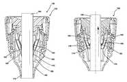
- FIG. 1Ais a side cross section of an embodiment of a surgical access device comprising an embodiment of an inverting shroud.
- FIG. 1Bis a cross section of a sealing assembly of the access device illustrated in FIG. 1A .
- FIG. 1Cis a detailed cross section of a proximal portion of the access device illustrated in FIG. 1A with an instrument inserted therein.
- FIG. 1Dis a cross section of an embodiment of the device illustrated in FIG. 1C with the instrument partially withdrawn.
- FIG. 1Eis a cross section of another embodiment of the device illustrated in FIG. 1C with the instrument partially withdrawn.
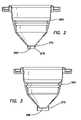
- FIG. 2is a cross section of an embodiment of a septum seal with an inverting shroud disposed thereon.
- FIG. 3is a cross section of an embodiment of a septum seal with an inverting shroud disposed thereon.
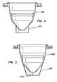
- FIG. 4is a cross section of an embodiment of a septum seal with an inverting shroud disposed thereon.
- FIG. 5is a cross section of an embodiment of a septum seal with an inverting shroud disposed thereon.
- FIG. 6is a cross section of an embodiment of a seal assembly comprising an embodiment of an inverting shroud disposed on a duckbill valve.
- an inverting shroudis used in a trocar-type access device.
- the inverting shroudis used in another type of surgical access device or system, for example, in a hand port, a single-port access system, and/or a limited port access system.
- FIG. 1Ais a longitudinal cross section of an embodiment of a surgical access device 100 in the form of a trocar comprising a proximal end, a distal end, and a longitudinal axis extending from the proximal end to the distal end.
- An instrument access channel 102coincides with the longitudinal axis in the illustrated embodiment.
- the surgical access devicecomprises a tubular cannula 110 comprising a lumen aligned with the access channel 102 , and a seal assembly 120 disposed at a proximal end of the cannula 110 .
- the cannula 110 and seal assembly 120are releasably coupled. In other embodiments, the cannula 110 and seal assembly 120 are integrated.
- An O-ring 112 captured at the proximal end of the cannula 110provides a fluid seal between the cannula 110 and the seal assembly 120 in the illustrated embodiment.
- the proximal end of the cannula 110further comprises a plurality of suture ties 114 .
- Embodiments of the cannula 110are rigid or flexible.
- FIG. 1Bis a longitudinal cross section of the seal assembly 120 taken through axis B-B in FIG. 1A .
- the seal assembly 120comprises a seal housing 130 on which is disposed a fluid connector 132 .
- the fluid connector 132comprises a Luer fitting and a stopcock.
- a cap or cover 140closes a proximal end of the seal housing 132 , securing within the housing 130 , a seal shield 150 , an instrument seal 160 , an inverting shroud 170 , and a zero seal 180 .
- the longitudinal axis and access channel 102extend through the seal housing 130 the cap 140 , the seal shield 150 , the instrument seal 160 , the inverting shroud 170 , and the duckbill valve 180 .
- the cap 140comprises a funneled entry 142 disposed at a proximal end thereof, and an alignment channel 144 distal of the funneled entry 142 .
- the funneled entry 142guides instruments into the access channel 102 , while the alignment channel 144 generally aligns an inserted instrument longitudinally with the access channel 102 . Aligning the instrument with the access channel reduces instrument contact with off-axis portions of the device 100 or components thereof, thereby reducing damage thereto.
- the cap 140is secured to the proximal end of the housing 130 using any suitable method, for example, mechanically (e.g., screw threads, clips, bayonet mounts, screws, latches, ratchets, pins, lock rings), adhesively (e.g., glue, epoxy, urethane, cyanoacrylate, pressure sensitive adhesive, polyvinyl alcohol adhesive, butadiene-styrene adhesive), welding (e.g., thermal, solvent, electron beam, laser, ultrasonic), magnetically, and the like.
- the cap 140is secured to the housing 130 by a combination of methods.
- the cannula 110 , housing 130 , and cap 140independently comprise suitable biologically compatible materials or combinations thereof, for example, metal, stainless steel, aluminum, nickel-titanium alloy, polymer resin, polycarbonate, polyester, polyamide (NYLON®, DELRIN®), aramid (KEVLAR®), polyimide, polyether block amide (PEBAX®), polyolefin, polyethylene (SPECTRA®), polypropylene, fluorinated polymers, epoxy, polystyrene, rubber, synthetic rubber, silicone, ethylene propylene diene monomer (EPDM), ethylene-propylene copolymer (EP rubber), polyisoprene, polybutadiene, polyurethane, styrene-butadiene, ethylene vinyl acetate (EVA), polychloroprene (NEOPRENE®), perfluoroelastomer (KALREZ®), polyvinyl chloride, polyvinylidene chloride, polycarbonate, polyvinyl chloride
- suitable materialscomprise copolymers, mixtures, blends, and/or alloys. Some embodiments of suitable materials comprise a composite, for example, a fiber reinforced polymer. Those skilled in the art will understand that different portions of a component comprise different materials in some embodiments.
- the illustrated embodimentcomprises an optional seal shield 150 , which reduces damage to the instrument seal 160 , for example from contact with a tip of an instrument inserted off-axis into the access channel 102 .
- the illustrated embodiment of the seal shield 150comprises a distal guide portion 152 that converges in a distal opening 152 aligned with the access channel 102 .
- the guide portion 152is generally frustoconical, defining a funnel entry that guides the tips of instruments to the opening 154 during insertion.
- Some embodiments of the seal shield 150comprise features that improve the guiding function, for example, longitudinal ribs or pleats disposed on the guide portion 152 .
- the illustrated seal shield 150is secured to the septum shield 160 .
- the opening 154 in the seal shield 150maintains alignment with an instrument opening 166 in the instrument shield 160 because the seal shield 150 moves in concert therewith.
- Embodiments of the seal shieldcomprise at least one of metal, stainless steel, polymer resin, polyolefin, polyethylene, polypropylene, polyvinyl chloride (PVC), polytetrafluoroethylene (PTFE, TEFLON®), polyamide (NYLON®, DELRIN®), copolymers, blends, mixtures, and the like.
- Some embodiments of the seal shield 150are not elastomeric.
- the instrument seal 160provides an instrument seal with instruments over a range of diameters.
- the instrument seal 160comprises a septum seal.
- the instrument seal 160comprises a radial flange 162 at a proximal end.
- the flange 160extends inwardly from at or near an inner wall of the housing 130 , towards the longitudinal axis.
- the flange 162comprises a convolution or bellows, which permits the instrument seal 160 to “float” or accommodate radial movement of an instrument extending therethrough.
- the convolution in the illustrated embodimentalso provides the instrument seal 160 with a degree of longitudinal movement in response to longitudinal instrument motion.
- a sealing portion 164 of the instrument sealconverges to an opening 166 aligned with the instrument channel 102 .
- the sealing portion 164is generally frustoconical, defining a funnel entry for instruments inserted therethrough.
- the sealing portion 164seals against an instrument extending through the opening 166 .
- at least the sealing portion 164 of the instrument sealcomprises an elastomeric material.
- the septum seal 160has a different configuration, for example, a disk shape rather than a cone shape.
- Other embodimentsuse another type of instrument seal, for example, a gel seal.
- the inverting shroud 170 in the illustrated embodimentcomprises a radial flange 172 at a proximal end thereof, and an inverting region 174 that converges to a distal aperture or opening 176 aligned with the access channel 102 .
- the flange 172 of the shroudextends inwardly from at or near the inner wall of the housing 130 , towards the longitudinal axis.
- Some embodiments of the flange 172comprise a convolution or bellows that allows the shroud 170 to float or move axially and/or laterally in response to instrument movements and/or movement of the septum seal 160 therein.
- the shroud 170then extends longitudinally to the inverting region 174 , which in the illustrated embodiment, is generally frustoconical, thereby defining a funnel entry for instruments.
- the inverting region 174has another shape, for example, cylindrical.
- the shroud 170is longer than the septum seal 160 . Accordingly, no part of the septum seal 160 extends through the aperture 176 of the shroud.
- the shroud 170is suspended, for example, on elastomeric bands and/or springs, which permit lateral and/or axial movement of the shroud 170 within the seal assembly 120 .
- Embodiments of the access device 100accommodate a wide range of instrument sizes, for example, with diameters of about 1 mm-16 mm or about 1 mm-25 mm. Other embodiments of the access device 100 accommodate a narrower range of instrument sizes, for example, with diameters of about 1 mm-5 mm, about 10 mm-12 mm, or about 10 mm-16 mm.
- a diameter of the aperture 176 of the shroudis at least as large as a diameter of the opening 166 of the septum seal. Accordingly, the shroud 170 does not contact instruments at a smaller end of the designed size range of the access device 100 that are aligned with the longitudinal axis. For example, for a trocar with an instrument range of 5 mm to 15 mm, the aperture 176 of the inverting shroud does not contact a 5 mm instrument aligned with the longitudinal axis.
- the illustrated embodiment of the inverting region 174further comprises one or more slits or slots 178 extending from the aperture 176 proximally into the inverting region 174 .
- the slitsreduce a drag force between the inverting shroud and large-diameter cylindrical instruments such as laparoscopes, thereby preventing the inverting region 174 of the shroud inverting when used with these types of instruments.
- a small-diameter aperture 176facilitates inversion of the shroud 170 by irregular features on an instrument; however, the small-diameter aperture 176 also increases drag on instruments.
- Embodiments of the slits 178reduce drag forces in embodiments comprising a small-diameter aperture 176 , thereby retaining the ease of inversion.
- Embodiments of the slits 178facilitate deflection of the inverting region 174 in response to contact with laparoscopic instruments, thereby reducing the likelihood of puncturing and/or tearing thereof, particularly by the tip of an instrument during the insertion thereof.
- Embodiments of the slits or slots 178also relieve pressure from insufflation gas, which would otherwise compress the shroud 170 against an instrument, thereby increasing drag thereon.
- Some embodiments of the shroud 170comprise one or more holes or vents as pressure reliefs.
- Embodiments of the inverting shroud 170have a wall thickness that allows pendulous movement of the septum seal 160 therein, for example, during off-axis manipulation of laparoscopic instruments.
- Embodiments of the inverting region 174 of the shroudcomprise a material with a lower coefficient of friction than the sealing portion 164 of the septum seal. Some embodiments of the inverting region 174 comprise a film. Some embodiments comprise a woven or non-woven fabric. Some embodiments comprise a composite, for example, a fabric embedded in a resin and/or a fiber reinforced polymer film. Embodiments of the inverting region 174 comprise an elastomeric material. Other embodiments of the inverting region 174 do not comprise an elastomeric material.
- Suitable materials for the inverting region 174include one or more polymer resins, for example, polyolefin, polyethylene, polypropylene, polyvinyl chloride (PVC), polyvinylidene chloride, polytetrafluoroethylene (PTFE, TEFLON®), polyester, polyamide (NYLON®, DELRIN®), aramid (Kevlar®), polyimide, polyether block amide (PEBAX®), fluorinated polymers, polyurethane, polyether, rubber, synthetic rubber, silicone, ethylene propylene diene monomer (EPDM), ethylene-propylene copolymer (EP rubber), polyisoprene, polybutadiene, polyurethane, styrene-butadiene, ethylene vinyl acetate (EVA), polychloroprene (NEOPRENE®), perfluoroelastomer (KALREZ®), thermoplastic elastomer (HYTREL®), PELLETHANE®, K
- the inverting shroud 170comprises a single material. In other embodiments, different sub-components of the inverting shroud, for example, the flange 172 and the inverting region 174 , comprise different materials. Embodiments of the inverting shroud 170 are manufactured by any suitable method, for example, transfer molding for polyisoprene or injection molding for silicone.
- Some embodiments of the inverting shroud 170further comprise a friction-reducing surface treatment and/or coating at least on portions that contact instruments.
- suitable surface treatments and/or coatingsinclude at least one of a hydrophilic polymer, silicone oil emulsion, silicone oil, silicone grease, polytetrafluoroethylene (PTFE, TEFLON®), cyanoacrylate, mineral oil, glycerin, polyxylylene xylylene (PARYLENE®), plasma surface treatment, and chlorination treatment.
- Some embodiments of the inverting shroud 170comprise a textured surface that reduces friction, for example, dots, bumps, ridges, stripes, and the like. Embodiments of the texture have a pattern or are random.
- the zero seal 180comprises a proximal flange 182 that extends inwardly from at or near the inner wall of the housing 130 towards the longitudinal axis and a duckbill valve or double duckbill valve 184 at a distal end thereof.
- the duckbill valve 184is aligned with the access channel 102 .
- the duckbill valve 184seals in the absence of an instrument extending therethrough, thereby preventing gas flow through the access channel 102 in the absence of an instrument and loss of pneumoperitoneum.
- Some embodiments of the access device 180do not comprise a zero seal, while in other embodiments, the instrument seal 160 is also a zero seal.
- the flange 162 of the instrument seal, the flange 172 of the shroud, and the flange 182 of the zero sealare sandwiched between the cap 140 and the housing 130 , thereby securing the instrument seal 160 , the shroud 170 , and the zero seal 180 .
- the flanges 162 , 172 , 182seal against each other, the cap 140 and the housing 130 , thereby preventing or reducing gas leaks therethrough.
- Each of the instrument seal 160 , the shroud 170 , and the zero seal 180extends distally from their respective flanges 162 , 172 , and 182 , and are nested, with the distal ends spaced to permit the unencumbered operation of each component.
- the seal shield 150is nested in the instrument seal 160 in the illustrated embodiment.
- a diameter of each of the seal shield 150 , the instrument seal 160 , and the shroud 170converge or taper from the proximal end to the distal end thereof with an opening or aperture aligned with the access channel 102 at the distal end thereof.
- FIG. 1Cis a view of the proximal end of the access device 100 , taken along the same section as FIG. 1A , with an instrument 190 inserted in the access channel 102 , and through the seal shield 150 , the instrument seal 160 , the shroud 170 , and zero seal 180 .
- the instrument 190comprises a protrusion 192 , which is advanced past the seal assembly 120 and into the cannula 110 in FIG. 1C . Because sealing portion 164 of the septum seal defines a funnel entry to the opening 166 , the protrusion 192 advances through the opening 166 without snagging or hanging-up thereon.
- the sealing portion 164 of the septum sealelongates distally and radially, to conform to the shaft of the instrument 190 , thereby forming a fluid-tight seal therewith.
- the inverting region 174 of the shroudalso conforms to the shaft of the instrument 190 in the illustrated embodiment.
- the inverting shroud 170is arranged and configured to reduce or prevent tearing of an instrument seal such as the illustrated septum seal 150 during the withdrawal and/or manipulation of a laparoscopic instrument 190 .
- an instrument sealsuch as the illustrated septum seal 150
- the protrusion 192has snagged or captured the aperture 176 of the shroud, thereby inverting the inverting portion 174 thereof.
- the protrusion 192draws the inverting portion 174 of the shroud through the opening 166 of the septum seal, thereby protecting or shielding the opening 166 of the septum shield from the protrusion 192 by lining or encasing the opening 166 . Consequently, the inverting portion 174 reduces or prevents damage, such as tearing, to the opening 166 of the septum seal 160 .
- the inverting portion 174 of the shroudalso extends through the opening 154 in the seal shield. Examples of instrument features that will induce the inverting region 174 of the shroud to invert include irregular tips such as L-hook monopolar electrodes and J-hook monopolar electrodes.
- an axial length of the inverting portion 174 of the shroudis sufficient to extend through the opening 166 of the septum seal in the inverted configuration.
- the inverting portion 174 of the shroudinverts during the withdrawal and/or manipulation of a laparoscopic instrument 190 with irregular features, which draw the inverting portion 174 through the opening 166 of the septum seal, effectively encasing the opening 166 of the septum seal therein in a protective funnel that guides the laparoscopic instrument 190 through the opening 166 of the septum seal.
- the septum seal 160 and septum shield 150do not invert. Only the inverting portion 174 of the shroud inverts in the illustrated embodiment.
- the inverting portion 174 of the shroudWith the inverting portion 174 of the shroud drawn through the opening 166 of the septum seal, irregular features of a laparoscopic instrument will not catch and/or tear the opening 166 of the septum seal. After the laparoscopic instrument 190 is completely withdrawn from the seal assembly 120 , the inverting portion 174 of the shroud reverts to the non-inverted configuration illustrated in FIG. 1B , driven by the resilient material thereof. Changing the direction of the instrument 190 in the access channel 102 will also revert the inverting portion 174 to the non-inverting configuration in some embodiments.
- FIG. 1Eillustrates a cross section of another embodiment of an access device 100 in which the instrument 190 is partially withdrawn compared with the configuration illustrated in FIG. 1C .
- withdrawing an instrument 190 comprising an irregularityin the illustrated embodiment, a protrusion 192 , induces inversion of the inverting portion 174 of the shroud.
- the protrusion 174catches the aperture 176 of the shroud, thereby inverting the inverting portion 174 , which then contacts the opening 166 and/or surrounding sealing portion 164 of the septum seal, thereby urging the sealing portion 164 of the septum seal around the opening 166 .
- a portion of the seal shield 150 around the opening 154also inverts.
- the inverting portion 174 of the shrouddoes not extend through the opening 166 of the septum seal.
- the inverting portion 174 of the shroudextends through opening 166 of the septum seal, thereby encasing and protecting the opening 166 of the septum seal, as discussed above.
- the inverted portion of the septum seal 160itself funnels the laparoscopic instrument 190 through the septum seal opening 166 as it is withdrawn.
- the rolled over edge of the inverted portion of the septum seal 160is less susceptible to catching and tearing compared with the edge of the opening 166 of a non-inverted septum seal 160 .
- the inverting portion 174 of the shroudencases the opening 166 of the septum seal, thereby defining a protective funnel that guides the laparoscopic instrument 190 through the opening 166 of the septum seal as the instrument 190 is withdrawn.
- inverting portion 174 of the shroudcomprises ribs or other reinforcing and/or stiffening members that collide with the portion of the septum seal 160 around the opening 166 , thereby facilitating the inversion thereof.
- a uniformly-shaped laparoscopic instrumentsuch as a laparoscope does not invert the inverting shroud 170 .
- withdrawing the uniformly-shaped instrumentalso does not invert these components. Drag force on the uniformly-shaped instrument is reduced during withdrawal thereof because the shroud 170 , septum seal 160 , and seal shield 150 remain in non-inverted configurations.
- Embodiments of the inverting shroud 170exhibit reduced the friction forces or drag forces associated with withdrawing a laparoscopic instrument.
- High drag forces produced experienced while withdrawing an instrumentcan result in inadvertent removal of the trocar cannula 110 and seal assembly 120 from the abdomen of the patient.
- the septum seal 160no longer directly contacts the instrument 190 , which contacts only the inverting shroud 170 .
- the inverting shroud 170has a lower coefficient of friction compared to the septum seal 160 , the drag or frictional force on withdrawing the instrument is reduced.
- the inverting portion 174 of the shroud in the inverted configurationseals a laparoscopic instrument 190 , thereby effectively maintaining pneumoperitoneum as the instrument 190 is withdrawn.
- FIGS. 2-5are side cross sections of embodiments in which an inverting shroud is coupled, secured, or integrated with a septum seal.
- an inverting shroud 270extends from a distal tip of a septum seal 260 .
- the inverting shroud 270is disposed at the opening 266 of the septum seal.
- the inverting shroud 270is a separately manufactured component, which is then secured to the septum seal 260 .
- the inverting shroud 270 and septum seal 260are integrated and manufactured as a single component, which reduces the number of steps and components in manufacturing the access device.
- the inverting shroud 270is dimensioned to enable the shroud 270 to invert and encase the opening 266 of the septum seal during instrument withdrawal, as discussed above.
- the shroud 270is generally cylindrical. In other embodiments, the shroud 270 has another shape, for example, frustoconical. Also, as discussed above, some embodiments of the shroud 270 comprise one or more slits or slots. In some embodiments, the inverting shroud 270 is also a secondary seal for instruments with diameters larger than the diameter of the aperture 276 of the shroud, for example, greater than 10 mm for an access device designed to accommodate instruments with diameters of from about 5 mm to about 15 mm
- the shroud 270moves in concert with the septum seal 260 , thereby reducing the likelihood that the inverting shroud 270 will adversely interfere with the function and movement of the septum seal 260 . Also, because the inverting shroud 270 moves in concert with the septum seal 260 , the inverting shroud 270 does not contact instruments with diameters smaller than the aperture 276 of the inverting shroud when instruments pivot the septum seal 260 from the longitudinal axis of the access device.
- FIG. 3illustrates another embodiment of a septum seal 360 on which an inverting shroud 370 is disposed.
- the embodiment illustrated in FIG. 3is generally similar to the embodiment illustrated in FIG. 2 , except that the inverting shroud 370 has a larger diameter, and consequently, is disposed farther from the opening 366 .
- inverting the shroud 370encases the opening 366 of the septum seal.
- inverting the shroud 370also inverts the portion of the septum seal around the opening 366 within the perimeter of the shroud 270 .
- FIG. 4illustrates another embodiment of a septum seal 460 on which an inverting shroud 470 is disposed.
- the embodiment illustrated in FIG. 4is generally similar to the embodiments illustrated in FIGS. 2 and 3 , except the inverting shroud 470 has an even larger diameter.
- FIG. 5illustrates another embodiment of a septum seal 560 on which an inverting shroud 570 is disposed.
- the embodiment illustrated in FIG. 5is similar to the embodiments illustrated in FIGS. 2-4 .
- the shroudis generally frustoconical and comprises at least one slit 578 .
- the slits 578define the shroud 570 as a plurality of strips or petals.
- FIG. 6illustrates an embodiment of a seal assembly 620 comprising a seal shield 650 , a septum seal 660 , an inverting shroud 670 , and a duckbill valve 680 disposed in a seal housing 630 and secured therein by a cap 640 .
- the seal assemblyis similar to the embodiment illustrated in FIG. 1B , except that the inverting shroud 670 in the illustrated embodiment is disposed on the duckbill valve 680 .
- the inverting shroud 670 and duckbill valve 680are manufactured separately, then assembled.
- the inverting shroud 670 and the duckbill valve 680are manufactured as a monolithic component.
Landscapes
- Health & Medical Sciences (AREA)
- Surgery (AREA)
- Life Sciences & Earth Sciences (AREA)
- Biomedical Technology (AREA)
- Nuclear Medicine, Radiotherapy & Molecular Imaging (AREA)
- Engineering & Computer Science (AREA)
- Pathology (AREA)
- Heart & Thoracic Surgery (AREA)
- Medical Informatics (AREA)
- Molecular Biology (AREA)
- Animal Behavior & Ethology (AREA)
- General Health & Medical Sciences (AREA)
- Public Health (AREA)
- Veterinary Medicine (AREA)
- Surgical Instruments (AREA)
Abstract
Description
Claims (17)
Priority Applications (1)
| Application Number | Priority Date | Filing Date | Title |
|---|---|---|---|
| US12/408,571US8075530B2 (en) | 2008-03-20 | 2009-03-20 | Instrument seal with inverting shroud |
Applications Claiming Priority (2)
| Application Number | Priority Date | Filing Date | Title |
|---|---|---|---|
| US3837908P | 2008-03-20 | 2008-03-20 | |
| US12/408,571US8075530B2 (en) | 2008-03-20 | 2009-03-20 | Instrument seal with inverting shroud |
Publications (2)
| Publication Number | Publication Date |
|---|---|
| US20090240204A1 US20090240204A1 (en) | 2009-09-24 |
| US8075530B2true US8075530B2 (en) | 2011-12-13 |
Family
ID=41089636
Family Applications (1)
| Application Number | Title | Priority Date | Filing Date |
|---|---|---|---|
| US12/408,571ActiveUS8075530B2 (en) | 2008-03-20 | 2009-03-20 | Instrument seal with inverting shroud |
Country Status (2)
| Country | Link |
|---|---|
| US (1) | US8075530B2 (en) |
| WO (1) | WO2009117694A2 (en) |
Cited By (41)
| Publication number | Priority date | Publication date | Assignee | Title |
|---|---|---|---|---|
| US8608769B2 (en) | 2001-09-24 | 2013-12-17 | Applied Medical Resources Corporation | Bladeless optical obturator |
| US8721539B2 (en) | 2010-01-20 | 2014-05-13 | EON Surgical Ltd. | Rapid laparoscopy exchange system and method of use thereof |
| US20140358115A1 (en)* | 2012-02-15 | 2014-12-04 | Np Medical Inc. | Multi-Purpose Protective Covering for Use on a Medical Device |
| US9000720B2 (en) | 2010-11-05 | 2015-04-07 | Ethicon Endo-Surgery, Inc. | Medical device packaging with charging interface |
| US9011427B2 (en) | 2010-11-05 | 2015-04-21 | Ethicon Endo-Surgery, Inc. | Surgical instrument safety glasses |
| US9011471B2 (en) | 2010-11-05 | 2015-04-21 | Ethicon Endo-Surgery, Inc. | Surgical instrument with pivoting coupling to modular shaft and end effector |
| US9017851B2 (en) | 2010-11-05 | 2015-04-28 | Ethicon Endo-Surgery, Inc. | Sterile housing for non-sterile medical device component |
| US9017849B2 (en) | 2010-11-05 | 2015-04-28 | Ethicon Endo-Surgery, Inc. | Power source management for medical device |
| US9039720B2 (en) | 2010-11-05 | 2015-05-26 | Ethicon Endo-Surgery, Inc. | Surgical instrument with ratcheting rotatable shaft |
| US9089338B2 (en) | 2010-11-05 | 2015-07-28 | Ethicon Endo-Surgery, Inc. | Medical device packaging with window for insertion of reusable component |
| US9138207B2 (en) | 2009-05-19 | 2015-09-22 | Teleflex Medical Incorporated | Methods and devices for laparoscopic surgery |
| US9161803B2 (en) | 2010-11-05 | 2015-10-20 | Ethicon Endo-Surgery, Inc. | Motor driven electrosurgical device with mechanical and electrical feedback |
| US9247986B2 (en) | 2010-11-05 | 2016-02-02 | Ethicon Endo-Surgery, Llc | Surgical instrument with ultrasonic transducer having integral switches |
| US9254125B2 (en) | 2001-09-24 | 2016-02-09 | Applied Medical Resources Corporation | Bladeless obturator |
| US9308009B2 (en) | 2010-11-05 | 2016-04-12 | Ethicon Endo-Surgery, Llc | Surgical instrument with modular shaft and transducer |
| US9314266B2 (en) | 2008-09-29 | 2016-04-19 | Applied Medical Resources Corporation | First-entry trocar system |
| US9375255B2 (en) | 2010-11-05 | 2016-06-28 | Ethicon Endo-Surgery, Llc | Surgical instrument handpiece with resiliently biased coupling to modular shaft and end effector |
| US9381058B2 (en) | 2010-11-05 | 2016-07-05 | Ethicon Endo-Surgery, Llc | Recharge system for medical devices |
| US9421062B2 (en) | 2010-11-05 | 2016-08-23 | Ethicon Endo-Surgery, Llc | Surgical instrument shaft with resiliently biased coupling to handpiece |
| US9427257B2 (en) | 2014-07-08 | 2016-08-30 | Applied Medical Resources Corporation | Highly responsive instrument seal |
| US9492062B2 (en) | 2006-10-06 | 2016-11-15 | Applied Medical Resources Corporation | Visual insufflation port |
| US9526921B2 (en) | 2010-11-05 | 2016-12-27 | Ethicon Endo-Surgery, Llc | User feedback through end effector of surgical instrument |
| US9545248B2 (en) | 2002-05-16 | 2017-01-17 | Applied Medical Resources Corporation | Blunt tip obturator |
| US9597143B2 (en) | 2010-11-05 | 2017-03-21 | Ethicon Endo-Surgery, Llc | Sterile medical instrument charging device |
| US9649150B2 (en) | 2010-11-05 | 2017-05-16 | Ethicon Endo-Surgery, Llc | Selective activation of electronic components in medical device |
| US9782214B2 (en) | 2010-11-05 | 2017-10-10 | Ethicon Llc | Surgical instrument with sensor and powered control |
| US9782215B2 (en) | 2010-11-05 | 2017-10-10 | Ethicon Endo-Surgery, Llc | Surgical instrument with ultrasonic transducer having integral switches |
| US10052088B2 (en) | 2010-01-20 | 2018-08-21 | EON Surgical Ltd. | System and method of deploying an elongate unit in a body cavity |
| US10085792B2 (en) | 2010-11-05 | 2018-10-02 | Ethicon Llc | Surgical instrument with motorized attachment feature |
| US10136938B2 (en) | 2014-10-29 | 2018-11-27 | Ethicon Llc | Electrosurgical instrument with sensor |
| US10226589B2 (en) | 2003-10-03 | 2019-03-12 | Applied Medical Resources Corporation | Insufflating optical surgical instrument |
| US10390694B2 (en) | 2010-09-19 | 2019-08-27 | Eon Surgical, Ltd. | Micro laparoscopy devices and deployments thereof |
| US10537380B2 (en) | 2010-11-05 | 2020-01-21 | Ethicon Llc | Surgical instrument with charging station and wireless communication |
| US10603101B2 (en) | 2016-03-26 | 2020-03-31 | Paul Joseph Weber | Apparatus, systems and methods for minimally invasive dissection of tissues |
| US10660695B2 (en) | 2010-11-05 | 2020-05-26 | Ethicon Llc | Sterile medical instrument charging device |
| US10881448B2 (en) | 2010-11-05 | 2021-01-05 | Ethicon Llc | Cam driven coupling between ultrasonic transducer and waveguide in surgical instrument |
| US10893899B2 (en) | 2016-03-26 | 2021-01-19 | Paul Weber | Apparatus and systems for minimally invasive dissection of tissues |
| US10959769B2 (en) | 2010-11-05 | 2021-03-30 | Ethicon Llc | Surgical instrument with slip ring assembly to power ultrasonic transducer |
| US10973563B2 (en) | 2010-11-05 | 2021-04-13 | Ethicon Llc | Surgical instrument with charging devices |
| US11510730B2 (en) | 2016-03-26 | 2022-11-29 | Paul Joseph Weber | Apparatus and methods for minimally invasive dissection and modification of tissues |
| US11602709B2 (en) | 2016-10-20 | 2023-03-14 | Emd Millipore Corporation | Valve protection and tube management device |
Families Citing this family (31)
| Publication number | Priority date | Publication date | Assignee | Title |
|---|---|---|---|---|
| US8579807B2 (en) | 2008-04-28 | 2013-11-12 | Ethicon Endo-Surgery, Inc. | Absorbing fluids in a surgical access device |
| US8915842B2 (en) | 2008-07-14 | 2014-12-23 | Ethicon Endo-Surgery, Inc. | Methods and devices for maintaining visibility and providing irrigation and/or suction during surgical procedures |
| US8690831B2 (en) | 2008-04-25 | 2014-04-08 | Ethicon Endo-Surgery, Inc. | Gas jet fluid removal in a trocar |
| US8568362B2 (en) | 2008-04-28 | 2013-10-29 | Ethicon Endo-Surgery, Inc. | Surgical access device with sorbents |
| US11235111B2 (en) | 2008-04-28 | 2022-02-01 | Ethicon Llc | Surgical access device |
| US8870747B2 (en) | 2008-04-28 | 2014-10-28 | Ethicon Endo-Surgery, Inc. | Scraping fluid removal in a surgical access device |
| US8273060B2 (en)* | 2008-04-28 | 2012-09-25 | Ethicon Endo-Surgery, Inc. | Fluid removal in a surgical access device |
| US9358041B2 (en) | 2008-04-28 | 2016-06-07 | Ethicon Endo-Surgery, Llc | Wicking fluid management in a surgical access device |
| US8636686B2 (en) | 2008-04-28 | 2014-01-28 | Ethicon Endo-Surgery, Inc. | Surgical access device |
| USD700326S1 (en) | 2008-04-28 | 2014-02-25 | Ethicon Endo-Surgery, Inc. | Trocar housing |
| US7981092B2 (en) | 2008-05-08 | 2011-07-19 | Ethicon Endo-Surgery, Inc. | Vibratory trocar |
| EP2378988B1 (en)* | 2009-01-09 | 2016-04-20 | Applied Medical Resources Corporation | Pleated trocar shield |
| CN101480354A (en)* | 2009-01-23 | 2009-07-15 | 周星 | Tank-type general purpose type radial seal ring for puncture outfit and puncture outfit |
| US8353874B2 (en)* | 2010-02-18 | 2013-01-15 | Covidien Lp | Access apparatus including integral zero-closure valve and check valve |
| JP6054298B2 (en)* | 2010-11-05 | 2016-12-27 | エシコン・エンド−サージェリィ・インコーポレイテッドEthicon Endo−Surgery,Inc. | Surgical instrument with modular end effector |
| CN102525600B (en)* | 2010-12-14 | 2016-06-22 | 周星 | The all-purpose sealed device of lower resistance and perforator for perforator |
| WO2013123455A1 (en) | 2012-02-15 | 2013-08-22 | Intuitive Surgical Operations, Inc. | Low friction cannula seals for minimally invasive robotic surgery |
| EP2846713A1 (en) | 2012-05-09 | 2015-03-18 | EON Surgical Ltd. | Laparoscopic port |
| WO2014116889A1 (en)* | 2013-01-24 | 2014-07-31 | Covidien Lp | Surgical seal assembly including an overlapping guard structure for a seal |
| DE102013101019A1 (en)* | 2013-02-01 | 2014-08-07 | Karl Storz Gmbh & Co. Kg | Sealing device for sealing a passage for a medical instrument |
| US9572626B2 (en) | 2013-02-15 | 2017-02-21 | Intuitive Surgical Operations, Inc. | Actuated cannula seal |
| CN104799911A (en)* | 2014-01-29 | 2015-07-29 | 伊西康内外科公司 | Puncture apparatus |
| US20150223833A1 (en)* | 2014-02-13 | 2015-08-13 | Jared COFFEEN | Trocar seal assembly |
| USD753303S1 (en) | 2014-07-29 | 2016-04-05 | Ethicon Endo-Surgery, Llc | Trocar |
| US10843203B2 (en) | 2016-03-17 | 2020-11-24 | Trade Fixtures, Llc | Viscous food product grinding and dispensing system |
| TWI642402B (en)* | 2016-11-10 | 2018-12-01 | 亞培高利控股有限公司 | Puncture device |
| JP6930874B2 (en)* | 2017-07-31 | 2021-09-01 | マニー株式会社 | Cannula holder |
| US20220361740A1 (en)* | 2018-05-11 | 2022-11-17 | Hao Kenith Fang | Methods and apparatus for a cleaning sheath for an endoscope |
| US20200391230A1 (en)* | 2019-06-11 | 2020-12-17 | Trade Fixtures, Llc | Viscous food dispensing nozzle |
| CN117257424B (en)* | 2023-11-23 | 2024-04-12 | 安徽通灵仿生科技有限公司 | Tearable sheath and method for manufacturing the same |
| CN119655693B (en)* | 2025-02-21 | 2025-08-15 | 浙江创想医学科技有限公司 | Rotatable transparent cap of endoscope |
Citations (7)
| Publication number | Priority date | Publication date | Assignee | Title |
|---|---|---|---|---|
| US5895377A (en)* | 1994-08-08 | 1999-04-20 | United States Surgical Corporation | Valve system for cannula assembly |
| US20050273133A1 (en) | 2003-08-26 | 2005-12-08 | Shluzas Alan E | Access systems and methods for minimally invasive surgery |
| US20060264991A1 (en)* | 2005-04-29 | 2006-11-23 | Applied Medical Resources Corporation | Seal housing having anti-inversion features |
| US20070027453A1 (en) | 2003-09-24 | 2007-02-01 | Applied Medical Resources Corporation | Anti-inversion trocar seal |
| US20070088277A1 (en) | 2005-10-14 | 2007-04-19 | Applied Medical Resources Corporation | Surgical access port |
| US20080065021A1 (en)* | 2006-09-07 | 2008-03-13 | Gyrus Medical Limited | Surgical instrument |
| US7470255B2 (en)* | 2004-07-21 | 2008-12-30 | Tyco Healthcare Group Lp | Introducer assembly with suspended seal |
- 2009
- 2009-03-20USUS12/408,571patent/US8075530B2/enactiveActive
- 2009-03-20WOPCT/US2009/037863patent/WO2009117694A2/enactiveApplication Filing
Patent Citations (7)
| Publication number | Priority date | Publication date | Assignee | Title |
|---|---|---|---|---|
| US5895377A (en)* | 1994-08-08 | 1999-04-20 | United States Surgical Corporation | Valve system for cannula assembly |
| US20050273133A1 (en) | 2003-08-26 | 2005-12-08 | Shluzas Alan E | Access systems and methods for minimally invasive surgery |
| US20070027453A1 (en) | 2003-09-24 | 2007-02-01 | Applied Medical Resources Corporation | Anti-inversion trocar seal |
| US7470255B2 (en)* | 2004-07-21 | 2008-12-30 | Tyco Healthcare Group Lp | Introducer assembly with suspended seal |
| US20060264991A1 (en)* | 2005-04-29 | 2006-11-23 | Applied Medical Resources Corporation | Seal housing having anti-inversion features |
| US20070088277A1 (en) | 2005-10-14 | 2007-04-19 | Applied Medical Resources Corporation | Surgical access port |
| US20080065021A1 (en)* | 2006-09-07 | 2008-03-13 | Gyrus Medical Limited | Surgical instrument |
Non-Patent Citations (1)
| Title |
|---|
| International Searching Authority/US, International Search Report and The Written Opinion of the International Searching Authority dated May 27, 2009, for International Application No. PCT/US2009/037863, filed Mar. 20, 2009, titled "Instrument Seal with Inverting Shroud". |
Cited By (75)
| Publication number | Priority date | Publication date | Assignee | Title |
|---|---|---|---|---|
| US10568658B2 (en) | 2001-09-24 | 2020-02-25 | Applied Medical Resources Corporation | Bladeless optical obturator |
| US9655643B2 (en) | 2001-09-24 | 2017-05-23 | Applied Medical Resources Corporation | Bladeless optical obturator |
| US8940009B2 (en) | 2001-09-24 | 2015-01-27 | Applied Medical Resources Corporation | Bladeless optical obturator |
| US8608769B2 (en) | 2001-09-24 | 2013-12-17 | Applied Medical Resources Corporation | Bladeless optical obturator |
| US9254125B2 (en) | 2001-09-24 | 2016-02-09 | Applied Medical Resources Corporation | Bladeless obturator |
| US9545248B2 (en) | 2002-05-16 | 2017-01-17 | Applied Medical Resources Corporation | Blunt tip obturator |
| US11207098B2 (en) | 2002-05-16 | 2021-12-28 | Applied Medical Resources Corporation | Blunt tip obturator |
| US10368906B2 (en) | 2002-05-16 | 2019-08-06 | Applied Medical Resources Corporation | Blunt tip obturator |
| US10918814B2 (en) | 2003-10-03 | 2021-02-16 | Applied Medical Resources Corporation | Insufflating optical surgical instrument |
| US10226589B2 (en) | 2003-10-03 | 2019-03-12 | Applied Medical Resources Corporation | Insufflating optical surgical instrument |
| US11123105B2 (en) | 2006-10-06 | 2021-09-21 | Applied Medical Resources Corporation | Visual insufflation port |
| US9492062B2 (en) | 2006-10-06 | 2016-11-15 | Applied Medical Resources Corporation | Visual insufflation port |
| US9358040B2 (en) | 2008-09-29 | 2016-06-07 | Applied Medical Resources Corporation | First-entry trocar system |
| US10022150B2 (en) | 2008-09-29 | 2018-07-17 | Applied Medical Resources Corporation | First-entry trocar system |
| US9314266B2 (en) | 2008-09-29 | 2016-04-19 | Applied Medical Resources Corporation | First-entry trocar system |
| US10856906B2 (en) | 2008-09-29 | 2020-12-08 | Applied Medical Resources Corporation | First-entry trocar system |
| US11723689B2 (en) | 2008-09-29 | 2023-08-15 | Applied Medical Resources Corporation | First-entry trocar system |
| US9138207B2 (en) | 2009-05-19 | 2015-09-22 | Teleflex Medical Incorporated | Methods and devices for laparoscopic surgery |
| US10499948B2 (en) | 2009-05-19 | 2019-12-10 | Teleflex Medical Incorporated | Methods and devices for laparoscopic surgery |
| US9737332B2 (en) | 2009-05-19 | 2017-08-22 | Teleflex Medical Incorporated | Methods and devices for laparoscopic surgery |
| US10052088B2 (en) | 2010-01-20 | 2018-08-21 | EON Surgical Ltd. | System and method of deploying an elongate unit in a body cavity |
| US10028652B2 (en) | 2010-01-20 | 2018-07-24 | EON Surgical Ltd. | Rapid laparoscopy exchange system and method of use thereof |
| US8721539B2 (en) | 2010-01-20 | 2014-05-13 | EON Surgical Ltd. | Rapid laparoscopy exchange system and method of use thereof |
| US10390694B2 (en) | 2010-09-19 | 2019-08-27 | Eon Surgical, Ltd. | Micro laparoscopy devices and deployments thereof |
| US9782214B2 (en) | 2010-11-05 | 2017-10-10 | Ethicon Llc | Surgical instrument with sensor and powered control |
| US10537380B2 (en) | 2010-11-05 | 2020-01-21 | Ethicon Llc | Surgical instrument with charging station and wireless communication |
| US9421062B2 (en) | 2010-11-05 | 2016-08-23 | Ethicon Endo-Surgery, Llc | Surgical instrument shaft with resiliently biased coupling to handpiece |
| US9510895B2 (en) | 2010-11-05 | 2016-12-06 | Ethicon Endo-Surgery, Llc | Surgical instrument with modular shaft and end effector |
| US9526921B2 (en) | 2010-11-05 | 2016-12-27 | Ethicon Endo-Surgery, Llc | User feedback through end effector of surgical instrument |
| US9381058B2 (en) | 2010-11-05 | 2016-07-05 | Ethicon Endo-Surgery, Llc | Recharge system for medical devices |
| US9597143B2 (en) | 2010-11-05 | 2017-03-21 | Ethicon Endo-Surgery, Llc | Sterile medical instrument charging device |
| US9649150B2 (en) | 2010-11-05 | 2017-05-16 | Ethicon Endo-Surgery, Llc | Selective activation of electronic components in medical device |
| US9375255B2 (en) | 2010-11-05 | 2016-06-28 | Ethicon Endo-Surgery, Llc | Surgical instrument handpiece with resiliently biased coupling to modular shaft and end effector |
| US11925335B2 (en) | 2010-11-05 | 2024-03-12 | Cilag Gmbh International | Surgical instrument with slip ring assembly to power ultrasonic transducer |
| US9364279B2 (en) | 2010-11-05 | 2016-06-14 | Ethicon Endo-Surgery, Llc | User feedback through handpiece of surgical instrument |
| US9308009B2 (en) | 2010-11-05 | 2016-04-12 | Ethicon Endo-Surgery, Llc | Surgical instrument with modular shaft and transducer |
| US9782215B2 (en) | 2010-11-05 | 2017-10-10 | Ethicon Endo-Surgery, Llc | Surgical instrument with ultrasonic transducer having integral switches |
| US9247986B2 (en) | 2010-11-05 | 2016-02-02 | Ethicon Endo-Surgery, Llc | Surgical instrument with ultrasonic transducer having integral switches |
| US9192428B2 (en) | 2010-11-05 | 2015-11-24 | Ethicon Endo-Surgery, Inc. | Surgical instrument with modular clamp pad |
| US9161803B2 (en) | 2010-11-05 | 2015-10-20 | Ethicon Endo-Surgery, Inc. | Motor driven electrosurgical device with mechanical and electrical feedback |
| US10085792B2 (en) | 2010-11-05 | 2018-10-02 | Ethicon Llc | Surgical instrument with motorized attachment feature |
| US11744635B2 (en) | 2010-11-05 | 2023-09-05 | Cilag Gmbh International | Sterile medical instrument charging device |
| US10143513B2 (en) | 2010-11-05 | 2018-12-04 | Ethicon Llc | Gear driven coupling between ultrasonic transducer and waveguide in surgical instrument |
| US11690605B2 (en) | 2010-11-05 | 2023-07-04 | Cilag Gmbh International | Surgical instrument with charging station and wireless communication |
| US9095346B2 (en) | 2010-11-05 | 2015-08-04 | Ethicon Endo-Surgery, Inc. | Medical device usage data processing |
| US9089338B2 (en) | 2010-11-05 | 2015-07-28 | Ethicon Endo-Surgery, Inc. | Medical device packaging with window for insertion of reusable component |
| US10376304B2 (en) | 2010-11-05 | 2019-08-13 | Ethicon Llc | Surgical instrument with modular shaft and end effector |
| US9072523B2 (en) | 2010-11-05 | 2015-07-07 | Ethicon Endo-Surgery, Inc. | Medical device with feature for sterile acceptance of non-sterile reusable component |
| US11389228B2 (en) | 2010-11-05 | 2022-07-19 | Cilag Gmbh International | Surgical instrument with sensor and powered control |
| US9039720B2 (en) | 2010-11-05 | 2015-05-26 | Ethicon Endo-Surgery, Inc. | Surgical instrument with ratcheting rotatable shaft |
| US9000720B2 (en) | 2010-11-05 | 2015-04-07 | Ethicon Endo-Surgery, Inc. | Medical device packaging with charging interface |
| US9017849B2 (en) | 2010-11-05 | 2015-04-28 | Ethicon Endo-Surgery, Inc. | Power source management for medical device |
| US9011427B2 (en) | 2010-11-05 | 2015-04-21 | Ethicon Endo-Surgery, Inc. | Surgical instrument safety glasses |
| US10660695B2 (en) | 2010-11-05 | 2020-05-26 | Ethicon Llc | Sterile medical instrument charging device |
| US9017851B2 (en) | 2010-11-05 | 2015-04-28 | Ethicon Endo-Surgery, Inc. | Sterile housing for non-sterile medical device component |
| US10881448B2 (en) | 2010-11-05 | 2021-01-05 | Ethicon Llc | Cam driven coupling between ultrasonic transducer and waveguide in surgical instrument |
| US10973563B2 (en) | 2010-11-05 | 2021-04-13 | Ethicon Llc | Surgical instrument with charging devices |
| US9011471B2 (en) | 2010-11-05 | 2015-04-21 | Ethicon Endo-Surgery, Inc. | Surgical instrument with pivoting coupling to modular shaft and end effector |
| US10945783B2 (en) | 2010-11-05 | 2021-03-16 | Ethicon Llc | Surgical instrument with modular shaft and end effector |
| US10959769B2 (en) | 2010-11-05 | 2021-03-30 | Ethicon Llc | Surgical instrument with slip ring assembly to power ultrasonic transducer |
| US10226613B2 (en)* | 2012-02-15 | 2019-03-12 | Np Medical Inc. | Multi-purpose protective covering for use on a medical device |
| US10953219B2 (en) | 2012-02-15 | 2021-03-23 | Np Medical Inc. | Multi-purpose protective covering for use on a medical device |
| US20140358115A1 (en)* | 2012-02-15 | 2014-12-04 | Np Medical Inc. | Multi-Purpose Protective Covering for Use on a Medical Device |
| US9724125B2 (en) | 2014-07-08 | 2017-08-08 | Applied Medical Resources Corporation | Highly responsive instrument seal |
| US9427257B2 (en) | 2014-07-08 | 2016-08-30 | Applied Medical Resources Corporation | Highly responsive instrument seal |
| US10492828B2 (en) | 2014-07-08 | 2019-12-03 | Applied Medical Resources Corporation | Highly responsive instrument seal |
| US10136938B2 (en) | 2014-10-29 | 2018-11-27 | Ethicon Llc | Electrosurgical instrument with sensor |
| US11510730B2 (en) | 2016-03-26 | 2022-11-29 | Paul Joseph Weber | Apparatus and methods for minimally invasive dissection and modification of tissues |
| US10603101B2 (en) | 2016-03-26 | 2020-03-31 | Paul Joseph Weber | Apparatus, systems and methods for minimally invasive dissection of tissues |
| US11771489B2 (en) | 2016-03-26 | 2023-10-03 | Paul J. Weber | Apparatus and systems for minimally invasive dissection of tissues |
| US11890048B2 (en) | 2016-03-26 | 2024-02-06 | Paul J. Weber | Apparatus and systems for minimally invasive dissection of tissues |
| US10893899B2 (en) | 2016-03-26 | 2021-01-19 | Paul Weber | Apparatus and systems for minimally invasive dissection of tissues |
| US12053228B2 (en) | 2016-03-26 | 2024-08-06 | Paul J. Weber | Apparatus and systems for minimally invasive dissection of tissues |
| US11602709B2 (en) | 2016-10-20 | 2023-03-14 | Emd Millipore Corporation | Valve protection and tube management device |
| US12090436B2 (en) | 2016-10-20 | 2024-09-17 | Emd Millipore Corporation | Valve protection and tube management device |
Also Published As
| Publication number | Publication date |
|---|---|
| US20090240204A1 (en) | 2009-09-24 |
| WO2009117694A2 (en) | 2009-09-24 |
| WO2009117694A3 (en) | 2010-03-18 |
Similar Documents
| Publication | Publication Date | Title |
|---|---|---|
| US8075530B2 (en) | Instrument seal with inverting shroud | |
| US8684975B2 (en) | Instrument seal | |
| CA2963528C (en) | Pleated trocar shield | |
| EP1997446B1 (en) | Access apparatus with shallow zero closure valve | |
| EP2098182A2 (en) | Single port device with multi-lumen cap | |
| EP2036507A1 (en) | Composite seal and method for manufacturing | |
| US20100036323A1 (en) | Flexible cannula with seal | |
| US20110009703A1 (en) | Flexible external cannula sheath | |
| EP1889580B1 (en) | Surgical seal assembly |
Legal Events
| Date | Code | Title | Description |
|---|---|---|---|
| AS | Assignment | Owner name:APPLIED MEDICAL RESOURCES CORPORATION, CALIFORNIA Free format text:ASSIGNMENT OF ASSIGNORS INTEREST;ASSIGNORS:TAYLOR, SCOTT V.;KAHLE, HENRY;MCGINLEY, KIMBALL B.;REEL/FRAME:022438/0589;SIGNING DATES FROM 20090323 TO 20090324 Owner name:APPLIED MEDICAL RESOURCES CORPORATION, CALIFORNIA Free format text:ASSIGNMENT OF ASSIGNORS INTEREST;ASSIGNORS:TAYLOR, SCOTT V.;KAHLE, HENRY;MCGINLEY, KIMBALL B.;SIGNING DATES FROM 20090323 TO 20090324;REEL/FRAME:022438/0589 | |
| STCF | Information on status: patent grant | Free format text:PATENTED CASE | |
| AS | Assignment | Owner name:CITIBANK, N.A., TEXAS Free format text:SECURITY AGREEMENT;ASSIGNOR:APPLIED MEDICAL RESOURCES CORPORATION;REEL/FRAME:028115/0276 Effective date:20120417 | |
| FPAY | Fee payment | Year of fee payment:4 | |
| AS | Assignment | Owner name:JPMORGAN CHASE BANK, N.A., AS ADMINISTRATIVE AGENT, ILLINOIS Free format text:SECURITY INTEREST;ASSIGNOR:APPLIED MEDICAL RESOURCES CORPORATION;REEL/FRAME:042669/0725 Effective date:20170531 Owner name:JPMORGAN CHASE BANK, N.A., AS ADMINISTRATIVE AGENT Free format text:SECURITY INTEREST;ASSIGNOR:APPLIED MEDICAL RESOURCES CORPORATION;REEL/FRAME:042669/0725 Effective date:20170531 | |
| MAFP | Maintenance fee payment | Free format text:PAYMENT OF MAINTENANCE FEE, 8TH YEAR, LARGE ENTITY (ORIGINAL EVENT CODE: M1552); ENTITY STATUS OF PATENT OWNER: LARGE ENTITY Year of fee payment:8 | |
| AS | Assignment | Owner name:CITIBANK, N.A., TEXAS Free format text:SECURITY INTEREST;ASSIGNOR:APPLIED MEDICAL RESOURCES CORPORATION;REEL/FRAME:056683/0001 Effective date:20210625 | |
| AS | Assignment | Owner name:APPLIED MEDICAL RESOURCES CORPORATION, CALIFORNIA Free format text:RELEASE BY SECURED PARTY;ASSIGNOR:JPMORGAN CHASE BANK, N.A.;REEL/FRAME:056751/0169 Effective date:20210625 | |
| MAFP | Maintenance fee payment | Free format text:PAYMENT OF MAINTENANCE FEE, 12TH YEAR, LARGE ENTITY (ORIGINAL EVENT CODE: M1553); ENTITY STATUS OF PATENT OWNER: LARGE ENTITY Year of fee payment:12 | |
| AS | Assignment | Owner name:BMO BANK N.A., AS ADMINISTRATIVE AGENT, CALIFORNIA Free format text:SECURITY INTEREST;ASSIGNOR:APPLIED MEDICAL RESOURCES CORPORATION;REEL/FRAME:066702/0123 Effective date:20240227 | |
| AS | Assignment | Owner name:APPLIED MEDICAL RESOURCES CORPORATION, CALIFORNIA Free format text:RELEASE BY SECURED PARTY;ASSIGNOR:CITIBANK N.A., AS ADMINISTRATIVE AGENT;REEL/FRAME:066796/0262 Effective date:20240129 Owner name:APPLIED MEDICAL RESOURCES CORPORATION, CALIFORNIA Free format text:RELEASE BY SECURED PARTY;ASSIGNOR:CITIBANK N.A., AS ADMINISTRATIVE AGENT;REEL/FRAME:066795/0595 Effective date:20240129 |