US8074851B2 - Car top carrier - Google Patents
Car top carrierDownload PDFInfo
- Publication number
- US8074851B2 US8074851B2US12/215,113US21511308AUS8074851B2US 8074851 B2US8074851 B2US 8074851B2US 21511308 AUS21511308 AUS 21511308AUS 8074851 B2US8074851 B2US 8074851B2
- Authority
- US
- United States
- Prior art keywords
- carrier
- floor
- box
- jaw
- clamp
- Prior art date
- Legal status (The legal status is an assumption and is not a legal conclusion. Google has not performed a legal analysis and makes no representation as to the accuracy of the status listed.)
- Expired - Fee Related, expires
Links
- 230000007246mechanismEffects0.000claimsdescription36
- 239000000969carrierSubstances0.000description7
- 230000000712assemblyEffects0.000description1
- 238000000429assemblyMethods0.000description1
- 230000000295complement effectEffects0.000description1
- 230000009977dual effectEffects0.000description1
- 230000005484gravityEffects0.000description1
- 238000007373indentationMethods0.000description1
- 238000004519manufacturing processMethods0.000description1
- 230000000284resting effectEffects0.000description1
Images


Classifications
- B—PERFORMING OPERATIONS; TRANSPORTING
- B60—VEHICLES IN GENERAL
- B60R—VEHICLES, VEHICLE FITTINGS, OR VEHICLE PARTS, NOT OTHERWISE PROVIDED FOR
- B60R9/00—Supplementary fittings on vehicle exterior for carrying loads, e.g. luggage, sports gear or the like
- B60R9/04—Carriers associated with vehicle roof
- B60R9/055—Enclosure-type carriers, e.g. containers, boxes
- B—PERFORMING OPERATIONS; TRANSPORTING
- B60—VEHICLES IN GENERAL
- B60R—VEHICLES, VEHICLE FITTINGS, OR VEHICLE PARTS, NOT OTHERWISE PROVIDED FOR
- B60R9/00—Supplementary fittings on vehicle exterior for carrying loads, e.g. luggage, sports gear or the like
- B60R9/04—Carriers associated with vehicle roof
- B60R9/058—Carriers associated with vehicle roof characterised by releasable attaching means between carrier and roof
Definitions
- the inventionrelates to assemblies for carrying cargo on a vehicle.
- the inventionprovides improvements for a box or trunk designed for mounting on top of a car.
- bracket systemstypically require the installer to reach extensively over the top of the car. Such bracket systems are impractical, particularly for a short person. The installer may have to practically climb into the open box to secure the brackets. This is especially a problem for a user who frequently wants to install or remove the carrier from the car.
- car top trunks or boxesare sometimes difficult to open.
- latches on the side of the boxthat opens.
- the usermay have to operate multiple latches simultaneously where the latches are separated by a long distance. This may require substantial strength, dexterity, and reach.
- Some boxeshave an actuator that coordinates simultaneous release of multiple latches but still may require special handling such as lifting of the cover while manipulating the actuator or handle. Accordingly, there is a need for enclosed car top carriers that are easy to mount on a vehicle and easy to use.
- An example of the inventionuses a mounting assembly that is quick and easy to install on a car.
- a preferred designuses a cam-operated clamping device to grip crossbars on a vehicle rack.
- Another example of the inventionuses coordinated hinge/latch devices to permit easy opening of the carrier from either side of a vehicle.
- Other examples and aspects of the inventionare described in detail below.
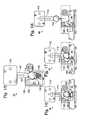
- FIG. 1is a side view of a car top carrier mounted on a vehicle.
- FIG. 2is an exploded view of a car top carrier.
- FIG. 3is a partial cut-away view of clamp 34 c in FIG. 1 gripping a crossbar.
- FIGS. 4 and 5are partial cut-away side views of the clamp in FIG. 3 as the cam lever moves toward the release position.
- FIG. 6is a top view of the clamp in FIG. 3 .
- FIG. 7is an end-on view of the clamp in FIG. 3 .
- FIG. 8is an inside view of a car top carrier with four clamps ganged together.
- FIG. 9is an inside view of a car top carrier with two clamps ganged together.
- FIGS. 10 and 11are end views of a car top carrier showing opening of the box from opposing sides.
- FIGS. 12-14are side views of a hinge/latch mechanism, for example, as shown in FIG. 2 .
- FIG. 15is a partial cut way view of a hinge/latch mechanism, for example, as shown in FIG. 2 .
- FIGS. 16-18are partial cut away views of a hinge/latch mechanism in operation.
- FIG. 19is an isolated side view of a lid support device, for example, as shown in FIG. 2 .
- FIG. 1shows car top carrier 20 mounted on vehicle 22 .
- Car top carrier 20includes top 24 and bottom 26 mounted on crossbars 28 on the top of car 22 .
- FIG. 2shows an exploded view of car top carrier or box 20 .
- Mounting hardwareis provided for easily securing carrier 20 to the vehicle rack.
- four mounting mechanisms 34 a - dmay be provided for this purpose.
- Each mounting mechanismincludes a cam lever for operating a jaw mechanism to clamp around a crossbar, as explained in more detail below.
- the clampsmay be provided completely preassembled with the box. The clamps never need to be disassembled as the carrier is put on and off one or more cars through the life of the product.
- Each clampmay be adjustable to grip, with variable force, crossbars of different dimensions.
- the clampsmay also be adjustable to different locations on the floor of the box, for example, along an axis parallel to the direction of vehicle travel.
- hinge/latch mechanisms 40 a - 40 care mounted on one side of carrier 20 to connect top 24 to bottom 26 .
- hinge/latch mechanisms 42 a - 42 cconnect top 24 to bottom 26 .
- Actuating bar 44is mounted inside carrier 20 for operating and synchronizing hinge/latch function of mechanisms 40 a - 40 c .
- Actuating bar 44may be operated, i.e., moved forward and backward relative to the long axis of carrier 20 , by manipulating switch, handle, or key device 46 from the exterior of carrier 20 .
- a similar actuating bar(not shown) is used to operate hinge/latch mechanisms 42 a - c via switch, handle, or key device 50 .
- Lid supports 54 a and 54 bare mounted at the front and back ends of carrier 20 , connecting top 24 to bottom 26 . Lid supports 54 a and 54 b stabilize top 24 when moving between open and closed positions. Lid supports 54 a and 54 b may also limit the extent of potential opening of carrier 20 . For example, lid supports 54 a , 54 b , may limit the extent of opening on either side of carrier 20 to approximately 16-inches. Longitudinal ribs or indentations 58 may be formed in carrier top 24 to provide stiffening and increased strength for carrier 20 , and may also be desirable aesthetically.
- FIGS. 3-7show details of one of the four mounting mechanisms, for example, as shown in FIG. 2 .
- FIG. 3is a side view of one of clamps 34 , with a portion of bottom 26 of carrier 20 cut-away. In closed position, cam lever 38 seats against floor 33 of bottom 26 . Cam lever 38 acts through cam portion 41 , shaft member 43 , bolt 45 , barrel nut 47 , and axle 49 to apply a force holding crossbar 28 tightly clamped between movable jaw portion 51 and stationary jaw portion 53 .
- FIGS. 4 and 5show details of clamp 34 moving to an unclamped position.
- Cam lever 38pivots around shaft member 43 .
- the shape of cam portion 41 and the position of shaft member 43causes opening and closing of movable jaw portion 51 relative to stationary jaw portion 53 when cam lever 38 is rotated between different positions as shown in FIGS. 3 to 5 .
- the jaw portionsmay define openings of different shapes for various purposes.
- the jaw portions in FIGS. 3-5define an elongate curved opening, or oval shape to accommodate crossbars having different cross-sectional shapes.
- Cam portion 41is shaped so that as lever 38 rotates around shaft member 43 the distance between shaft member 43 and floor 33 is altered, thus causing corresponding pivotal movement of jaw portion 51 toward or away from fixed stationary jaw portion 53 mounted on floor 33 .
- Movable jaw portion 51pivots around axle structure 49 .
- Movable jaw portion 51is elongate, with an initial portion 55 angled so as to guide crossbar 28 into position between movable jaw portion 51 and stationary jaw portion 53 .
- Movable jaw portion 51has a concave inner surface 57 which contacts crossbar 28 when the jaw is closed, and which is configured for gripping. Concave inner surface 57 may have a cushion or pad 59 near axle 49 .
- Stationary jaw portion 53may have side tabs 61 to guide movable jaw portion 51 when clamp 34 is moved to the closed position.
- Clamp 34is mounted on floor 33 of carrier bottom 26 by bolt 45 , with barrel nut 47 serving us an anchor pivot for bolt 45 .
- a first oversize knob 63turns bolt 45 to move barrel nut 47 closer to or farther away from shaft member 43 , thereby providing a gross adjustment mechanism for the tightness of the clamping action.
- Movable jaw portion 51clamps around crossbar 28 .
- arrow 64indicates the direction of forward travel of vehicle 26 .
- Movable jaw portion 51preferably is oriented to open in the forward direction to make carrier 20 less likely to be dislodged from vehicle 22 in a high-impact forward collision.
- FIG. 6shows a top view of clamp 34 .
- Bolt 45passes from the inside of car top carrier 20 to the outside through floor 33 of carrier bottom 26 via slot 66 which is aligned with the long axis of car top carrier 20 .
- Slot 66allows adjustment of the location of clamp 34 along the long axis of car top carrier 20 .
- Finger tabs 68facilitate prying or lifting of cam lever 38 away from floor 33 when opening clamp 34 .
- Cam lever 38is shaped to provide clearance for first oversize knob 62 when cam lever 38 is moved between open and closed positions.
- a second oversize knob 70provides for tightening or loosening of fastener 72 passing through slot 66 to stationary jaw component 53 to prevent or allow motion of clamp 34 in slot 66 .
- Floor 33 of bottom 30is shaped in the form of a ridge or rail 74 to complement the shape of clamp 34 and to aid in seating cam lever 38 against floor 33 when clamp 34 is in the closed position, thereby providing repeatable and secure alignment.
- FIG. 7is an end-on view of clamp 34 , as shown in FIG. 6 .
- Shaft member 43may include curvature away from barrel nut 47 so as to provide spring action during operation of clamp 34 .
- clampsmay be used to fasten a container on a set of crossbars on top of a vehicle.
- one, two or more clampsmay be used to secure a container on a front crossbar.
- one, two or more clampsmay be used to secure a container to a rear crossbar.
- a single clampmay be sufficient, for example, on the front crossbar with the container merely resting on the back crossbar.
- a single clampmay be used on each crossbar, or multiple clamps may be used on one or both crossbars.
- a clampas described above, may also be modified to provide automatic clamping.
- the movable jaw portionmay be spring biased toward the closed position.
- the lip of the jawmay be configured to cause opening of the jaw as the box slides forward across the top of the crossbars. Once the jaw encompasses the crossbar, it springs back to a secure closed position.
- the jawis further configured so that it cannot be opened without a manipulation, for example, switch or lever-operated, action inside the box. This type of fastener may be referred to as “seat belt type engagement.”
- a jaw member as described abovemay have different shapes.
- the jaw membermay be generically shaped to fit around differently shaped or dimensioned crossbars.
- the jaw membermay be custom-shaped to fit around a specific crossbar configuration.
- the jaw membermay have a partially rectangular inner surface for fitting around a rectangular or square cross bar.
- Clamping devicesshould be designed to minimize manufacturing costs and complexity.
- a rail with a slotas described above, may be molded into the floor of a box.
- a stationary jaw portion, movable jaw portion, and cam levermay be separately molded pieces.
- clamp mechanisms shown and described hereinmay be implemented on boxes with any type of hinge and/or latch mechanism.
- the clamping devicesmay be used on a box with dual functioning hinges that can operate as a hinge or a latch, for example, as described in U.S. Pat. No. 5,823,411 and U.S. Provisional Patent Application No. 60/443,437, each of which is hereby incorporated by reference in its entirety.
- FIGS. 10 and 11show end views of car top carrier 20 opened alternately from opposite sides. This feature of carrier 20 is made possible by dual-functioning hinge/latch mechanisms such as the examples described in detail below.
- plunger 150urges enlarged end portion 114 upward so that it disengages from receiving portion 120 even when pawl 122 is permitted to rotate back to its original orientation.
- the spring and plunger mechanismmakes it easier to open the carrier because once the actuating bar has simultaneously pushed multiple pawl members out of the way in each of the coordinated hinge/latch mechanisms, the latches are disengaged without further manual movement or handling relative to carrier top 24 .
- enlarged end portion 114is forced into receiving portion 120 until pawl 122 is pushed aside allowing enlarged end portion 114 to “snap” into place, as shown in FIG. 15 .
- the springsmay be selected such that very little, if any, manual force is required, in addition to gravity, to latch the top closed, somewhat analogous to the closing of a trunk on a car.
- FIGS. 16-18show movement of actuating bar 44 to disengage enlarged end portion 114 from receiving portion 120 .
- actuating bar 44has a projection 160 that is normally spaced away from end portion 162 of pawl member 122 when hinge/latch mechanism 40 a is functioning as a hinge.
- projection 160 of actuating bar 144contacts and pushes end portion 162 of pawl member 122 . This eventually causes rotation of pawl member 122 out of the way of the main receiving channel in receiving portion 120 , thus allowing enlarged end portion 114 to disengage receiving portion 120 , enabling hinge/latch mechanism 40 a to function as a latch.
- FIG. 19shows a lid support, for example, such as 54 b in FIG. 2 .
- First arm 202may be connected to bottom 26 of carrier 20 .
- Second arm 204may be connected to top 24 of carrier 20 .
- First arm 202is pivotally connected second arm 204 .
- Spring 206is contained in a pocket in first arm 202 .
- Spring 206acts on slide or cam follower 208 which moves up and down as second arm 204 is moved between open and closed positions.
- Second arm 204has a cam portion 210 than contacts slide 208 .
- the shape of cam portion 206determines the magnitude and direction of torque exerted on second arm 204 about pivot point 212 .
Landscapes
- Engineering & Computer Science (AREA)
- Mechanical Engineering (AREA)
- Fittings On The Vehicle Exterior For Carrying Loads, And Devices For Holding Or Mounting Articles (AREA)
Abstract
Description
Claims (7)
Priority Applications (2)
| Application Number | Priority Date | Filing Date | Title |
|---|---|---|---|
| US12/215,113US8074851B2 (en) | 2003-01-28 | 2008-06-24 | Car top carrier |
| US13/323,652US8757457B2 (en) | 2003-01-28 | 2011-12-12 | Car top carrier |
Applications Claiming Priority (4)
| Application Number | Priority Date | Filing Date | Title |
|---|---|---|---|
| US44343703P | 2003-01-28 | 2003-01-28 | |
| US10/767,398US7503470B2 (en) | 2003-01-28 | 2004-01-28 | Car top carrier |
| US11/219,578US7416098B2 (en) | 2003-01-28 | 2005-09-02 | Car top carrier |
| US12/215,113US8074851B2 (en) | 2003-01-28 | 2008-06-24 | Car top carrier |
Related Parent Applications (1)
| Application Number | Title | Priority Date | Filing Date |
|---|---|---|---|
| US11/219,578ContinuationUS7416098B2 (en) | 2003-01-28 | 2005-09-02 | Car top carrier |
Related Child Applications (1)
| Application Number | Title | Priority Date | Filing Date |
|---|---|---|---|
| US13/323,652ContinuationUS8757457B2 (en) | 2003-01-28 | 2011-12-12 | Car top carrier |
Publications (2)
| Publication Number | Publication Date |
|---|---|
| US20090014489A1 US20090014489A1 (en) | 2009-01-15 |
| US8074851B2true US8074851B2 (en) | 2011-12-13 |
Family
ID=35799031
Family Applications (4)
| Application Number | Title | Priority Date | Filing Date |
|---|---|---|---|
| US10/767,398Expired - Fee RelatedUS7503470B2 (en) | 2003-01-28 | 2004-01-28 | Car top carrier |
| US11/219,578Expired - LifetimeUS7416098B2 (en) | 2003-01-28 | 2005-09-02 | Car top carrier |
| US12/215,113Expired - Fee RelatedUS8074851B2 (en) | 2003-01-28 | 2008-06-24 | Car top carrier |
| US13/323,652Expired - Fee RelatedUS8757457B2 (en) | 2003-01-28 | 2011-12-12 | Car top carrier |
Family Applications Before (2)
| Application Number | Title | Priority Date | Filing Date |
|---|---|---|---|
| US10/767,398Expired - Fee RelatedUS7503470B2 (en) | 2003-01-28 | 2004-01-28 | Car top carrier |
| US11/219,578Expired - LifetimeUS7416098B2 (en) | 2003-01-28 | 2005-09-02 | Car top carrier |
Family Applications After (1)
| Application Number | Title | Priority Date | Filing Date |
|---|---|---|---|
| US13/323,652Expired - Fee RelatedUS8757457B2 (en) | 2003-01-28 | 2011-12-12 | Car top carrier |
Country Status (1)
| Country | Link |
|---|---|
| US (4) | US7503470B2 (en) |
Cited By (9)
| Publication number | Priority date | Publication date | Assignee | Title |
|---|---|---|---|---|
| US20110084103A1 (en)* | 2009-10-12 | 2011-04-14 | Hapro International B.V. | Attachment device for a roof rack |
| US20120145757A1 (en)* | 2003-01-28 | 2012-06-14 | Yakima Products, Inc. | Car top carrier |
| US8807407B2 (en) | 2010-09-08 | 2014-08-19 | Yakima Innovation Development Corporation | Clamping assembly for a roof box carrier having an adjustment mechanism |
| US8944303B1 (en)* | 2012-02-23 | 2015-02-03 | Garry L. Campbell | Clamp-on saddle bag mounting system |
| US9290131B2 (en) | 2012-07-30 | 2016-03-22 | Yakima Products, Inc. | Carrier for a vehicle |
| US20190217786A1 (en)* | 2009-06-15 | 2019-07-18 | Yakima Products, Inc. | Crossbar clamp devices |
| US11325539B2 (en) | 2019-03-08 | 2022-05-10 | Yakima Products, Inc. | Fishing gear carrier box |
| US11364171B2 (en)* | 2017-07-27 | 2022-06-21 | Medline Industries, Lp | Dual receptacle carrier |
| US12187237B2 (en)* | 2022-11-14 | 2025-01-07 | Ningbo Pinchuan Auto Parts Co., Ltd. | Snowboard carrier for automobile roof |
Families Citing this family (59)
| Publication number | Priority date | Publication date | Assignee | Title |
|---|---|---|---|---|
| US7066532B2 (en)* | 2002-11-12 | 2006-06-27 | Lear Corporation | Ultrathin structural panel with rigid insert |
| DE102004035154B4 (en)* | 2004-07-20 | 2023-06-07 | Thule Gmbh & Co. Kg | Mounting device for attaching a roof box |
| US20090045237A1 (en)* | 2005-05-26 | 2009-02-19 | Kunz James R | Storage container docking system |
| US20060266777A1 (en)* | 2005-05-31 | 2006-11-30 | Ching-Ho Huang | Beach buggy case |
| US7980436B2 (en)* | 2005-07-01 | 2011-07-19 | Yakima Products, Inc. | Cargo box gear mounting assembly |
| US7712762B1 (en)* | 2005-08-25 | 2010-05-11 | Wendell Everett Miller | Vehicle-attachable apparatus |
| US20070205240A1 (en)* | 2005-10-21 | 2007-09-06 | Jeff Castro | Vehicle top carriers |
| US20070164066A1 (en)* | 2005-11-08 | 2007-07-19 | Peter Jones | Vehicle top carrier with gull wing doors |
| US20070194185A1 (en)* | 2005-11-29 | 2007-08-23 | Jason Carothers | Vehicle top carriers |
| US7740157B2 (en)* | 2006-01-23 | 2010-06-22 | Yakima Products, Inc. | Coordinated latching mechanism for car top carrier |
| US20080017679A1 (en)* | 2006-07-19 | 2008-01-24 | Philippe Leblanc | Roof box for a vehicle |
| US7798381B2 (en)* | 2006-10-25 | 2010-09-21 | Salflex Polymers Ltd. | Collapsible roof basket carrier |
| US20110174855A1 (en)* | 2006-11-29 | 2011-07-21 | Yakima Products, Inc. | Vehicle top carriers |
| US20080264989A1 (en)* | 2007-04-26 | 2008-10-30 | Thomas John Barquinero | Roof rack carrier system incorporating a rotary latch |
| NZ561811A (en) | 2007-09-21 | 2010-06-25 | Hubco Automotive Ltd | Extendable roof rack |
| EP2303641B1 (en)* | 2008-06-23 | 2012-11-28 | Yakima Products, Inc. | Rack tower for securing crossbars on top of a vehicle |
| CA2729120A1 (en)* | 2008-06-27 | 2009-12-30 | Yakima Products, Inc. | Car top carrier |
| US8292139B2 (en)* | 2008-11-04 | 2012-10-23 | Trek Bicycle Corporation | Bicycle pannier mounting system |
| JP5396077B2 (en)* | 2008-12-24 | 2014-01-22 | 株式会社カーメイト | In-vehicle roof box |
| US8496145B2 (en)* | 2009-06-05 | 2013-07-30 | Yakima Innovation Development Corporation | Vehicle rack for carrying a wheel |
| US8282254B2 (en)* | 2009-09-04 | 2012-10-09 | Yakima Products, Inc. | Cargo carrier with aerodynamic illumination device |
| EP2322382A1 (en)* | 2009-11-16 | 2011-05-18 | Zadi S.p.A. | Locking system for cases and vehicle roof boxes |
| US20110186608A1 (en)* | 2010-01-29 | 2011-08-04 | Yakima Products, Inc. | Car top carrier lid support |
| USD636326S1 (en)* | 2010-02-08 | 2011-04-19 | Hubco Automotive Ltd. | Roof box |
| CN102869543B (en)* | 2010-02-08 | 2015-12-16 | 胡布科汽车有限公司 | Load carrying arrangement |
| WO2011145952A1 (en)* | 2010-05-17 | 2011-11-24 | Hubco Automotive Limited | Clamping mechanism |
| WO2012008853A1 (en)* | 2010-06-07 | 2012-01-19 | Hubco Automotive Limited | Securing mechanism |
| NZ587637A (en)* | 2010-08-27 | 2013-03-28 | Thule Ip Ab | A pannier frame assembly on a bike rack having front and rear adjustment |
| US20120228349A1 (en) | 2010-10-05 | 2012-09-13 | Yakima Products, Inc. | Stabilized cargo box for a vehicle rack system |
| US8662365B2 (en)* | 2010-11-22 | 2014-03-04 | Winston Products Llc | Hard-shell cargo carrier |
| CA2804536A1 (en)* | 2011-02-23 | 2012-08-30 | Howard BERREY | Vehicle roof top boat storage unit |
| WO2013102244A1 (en)* | 2012-01-06 | 2013-07-11 | Santobin Pty Ltd | Securing apparatus |
| USD714211S1 (en) | 2012-02-22 | 2014-09-30 | Howard Berrey | Vehicle roof top boat storage unit |
| US20140191004A1 (en)* | 2012-04-30 | 2014-07-10 | Yakima Innovation Development Corporation | Universal gunwale bracket |
| AU2013255540A1 (en) | 2012-04-30 | 2014-12-18 | Yakima Australia Pty Limited | Retention dock |
| KR101306520B1 (en)* | 2012-06-20 | 2013-09-09 | 황문진 | Boat for combining with roof box |
| USD726638S1 (en)* | 2012-07-31 | 2015-04-14 | Thule Sweden Ab | Roof top cargo box |
| USD717719S1 (en)* | 2012-09-11 | 2014-11-18 | Hubco Automotive Limited | Cargo box |
| USD717228S1 (en)* | 2012-09-11 | 2014-11-11 | Hubco Automotive Limited | Cargo box |
| USD722006S1 (en)* | 2012-09-11 | 2015-02-03 | Thule Sweden Ab | Automotive rooftop cargo box |
| USD739336S1 (en) | 2013-06-20 | 2015-09-22 | Howard Berrey | Vehicle roof top boat storage unit |
| EP3024702B1 (en)* | 2013-07-26 | 2017-09-27 | Thule Sweden AB | Convertible mounting bracket |
| CN105813896A (en)* | 2013-10-17 | 2016-07-27 | 艾罗运动有限公司 | An apparatus for mounting an article to a vehicle, and an article for use therewith |
| US9694757B2 (en) | 2014-01-08 | 2017-07-04 | Yakima Innovation Development Corporation | Board carrier |
| US20160039351A1 (en)* | 2014-08-05 | 2016-02-11 | Thule Sweden Ab | Load carrier assemblies for securing a load to a vehicular crossbar |
| USD773378S1 (en) | 2015-06-09 | 2016-12-06 | Yakima Products, Inc. | Vehicle top carrier |
| US10040403B2 (en) | 2015-06-09 | 2018-08-07 | Yakima Products, Inc. | Crossbar clamp actuator |
| NO3112217T3 (en)* | 2015-07-02 | 2018-06-09 | ||
| JP6562816B2 (en)* | 2015-10-27 | 2019-08-21 | 株式会社カーメイト | Roof box |
| WO2017214058A1 (en) | 2016-06-05 | 2017-12-14 | Yakima Products, Inc. | Vehicle rooftop rack assembly |
| CN109641558B (en) | 2016-06-05 | 2022-09-16 | 雅捷马产品公司 | Upright Bike Carrier |
| EP3478537A1 (en) | 2016-06-30 | 2019-05-08 | Horizon Global Americas Inc. | Vehicle roof box with central, external attachment system |
| US10246026B1 (en)* | 2017-03-22 | 2019-04-02 | Impact Plastics Corporation | Car top carrier and hinge therefor |
| EP3581435B1 (en)* | 2018-06-13 | 2021-03-17 | Thule Sweden AB | Vehicle carrier box |
| US11364852B2 (en)* | 2019-04-17 | 2022-06-21 | Bombardier Recreational Products Inc. | Storage box assembly for a vehicle |
| US11351928B2 (en)* | 2019-06-03 | 2022-06-07 | Yakima Products, Inc. | Torque limiting clamp actuator |
| JP7649763B2 (en)* | 2022-03-08 | 2025-03-21 | Piaa株式会社 | Roof box clamping device for vehicles |
| US12351365B2 (en)* | 2022-10-26 | 2025-07-08 | Rivian Ip Holdings, Llc | Storage bin |
| US12325382B2 (en)* | 2023-03-28 | 2025-06-10 | Donald Dunn | Ladder-mounted storage system |
Citations (46)
| Publication number | Priority date | Publication date | Assignee | Title |
|---|---|---|---|---|
| US1313687A (en) | 1919-08-19 | Henry hellweg | ||
| US2483947A (en) | 1947-10-18 | 1949-10-04 | Turner Alonzo Robert | Cover lift hinge |
| US3008177A (en)* | 1960-03-21 | 1961-11-14 | Jr Frank A Wooten | Trunk hinge and latch |
| US3366295A (en) | 1966-02-03 | 1968-01-30 | Andrew G. Nygaard | Car luggage carrier |
| US3677196A (en) | 1969-12-19 | 1972-07-18 | Pullman Inc | Covered hopper car |
| DE2804588A1 (en) | 1978-02-03 | 1979-08-09 | Daimler Benz Ag | Security device for roof rack luggage - has sprung tongues which grip under roof rack, and locks at ends of cross members |
| US4217999A (en)* | 1978-02-16 | 1980-08-19 | Forsman Armerad Plast Ab | Skicase |
| US4249684A (en)* | 1979-03-22 | 1981-02-10 | Le Roy Dombeck | Removably anchored box |
| US4274568A (en) | 1979-05-15 | 1981-06-23 | Bott John Anthony | Combination of luggage carrier and personal luggage |
| US4378898A (en)* | 1980-12-24 | 1983-04-05 | Smeenge Paul A | Cargo carrier |
| US4406387A (en)* | 1981-03-30 | 1983-09-27 | Masco Corporation | Article carrier |
| US4420105A (en) | 1982-09-30 | 1983-12-13 | Nepper John P | Flexible hinge and closure member for a luggage carrier |
| DE3817470A1 (en) | 1988-05-21 | 1989-11-23 | Jetbag Gmbh | Mounting device for roof box |
| DE3837209C1 (en) | 1988-11-02 | 1990-03-01 | Kamei-Porotherm Gmbh & Co Kg, 3180 Wolfsburg, De | Roof rack |
| EP0422678A1 (en) | 1989-10-13 | 1991-04-17 | silvretta-sherpas Sportartikel GmbH | Luggage carrier |
| US5280848A (en) | 1991-04-23 | 1994-01-25 | Rover Group Limited | Motor vehicle interior fitting |
| DE4340019C1 (en) | 1993-11-24 | 1995-04-20 | Oris Fahrzeugteile Riehle H | Container for the transport of goods on vehicles |
| US5419479A (en) | 1993-05-06 | 1995-05-30 | Happich Fahrzeug-Dachsysteme Gmbh | Transverse carrier clamp for roof luggage carrier for automotive vehicles with roof rack |
| JPH07172452A (en) | 1993-10-02 | 1995-07-11 | Huwil Werke Gmbh Moebelschloss & Beschlagfab | Support for holding the lid member |
| US5492258A (en)* | 1993-10-08 | 1996-02-20 | Gebr. Happich Gmbh | Cross support for roof loads on a motor vehicle provided with roof railings |
| DE19526477C1 (en) | 1995-07-20 | 1996-09-12 | Jetbag Gmbh | Holder for detachable fastening of roof storage boxes on motor vehicles |
| JPH08258630A (en) | 1995-03-27 | 1996-10-08 | Kaameito:Kk | Two-side opening roof box |
| US5582316A (en) | 1992-08-28 | 1996-12-10 | S&B Foods, Inc. | Cap operating mechanism |
| US5582313A (en) | 1992-05-19 | 1996-12-10 | Dynamid Co., Ltd. | Deposit container of roof box type |
| WO1997011865A1 (en) | 1995-09-25 | 1997-04-03 | Mont Blanc Industri Ab | A device for releasable attachment of a load-carrier accessory unit for vehicles |
| US5762244A (en)* | 1996-11-22 | 1998-06-09 | Bornemann Products, Inc. | Utility rack |
| US5823411A (en)* | 1993-11-24 | 1998-10-20 | Huwil-Werke Gmbh | Locking device for suitcases and trunks, especially roof trunks for motor vehicles |
| US5845828A (en) | 1996-01-12 | 1998-12-08 | Yakima Products | Tower assembly for mounting a crossbar to a vehicle roof rack |
| DE19742253C1 (en) | 1997-09-25 | 1999-05-06 | Huwil Werke Gmbh | Roof casing actuator for motor vehicle |
| US5947356A (en)* | 1998-07-10 | 1999-09-07 | Delong; Ronald C. | Quick latch system for tool box |
| JPH11291832A (en) | 1998-04-06 | 1999-10-26 | Car Mate Mfg Co Ltd | Openable roof box |
| EP0983903A1 (en) | 1998-09-04 | 2000-03-08 | Hapro International B.V. | A fastening system for attaching a roof box to a frame, as well as roof box provided with such a fastening system |
| US6145719A (en)* | 1999-08-12 | 2000-11-14 | Robert; Louis J. | Vehicle mountable gun and equipment case |
| US6273311B1 (en)* | 1999-07-16 | 2001-08-14 | Fabio Pedrini | Carrier for a motor-vehicle roof |
| US6296278B1 (en) | 1998-08-27 | 2001-10-02 | Ise Innomotive Systems Europe Gmbh | Rollover protection apparatus |
| US20020030074A1 (en) | 2000-08-10 | 2002-03-14 | Vincent Bove | Roof-top load basket |
| EP1190906A2 (en) | 2000-09-26 | 2002-03-27 | Thule GmbH & Co. KG | Fastening device, especially for a roof box |
| EP1231112A2 (en) | 2001-02-13 | 2002-08-14 | AUTOTEK S.r.l. | Car roof box with improved closure means |
| US6463627B1 (en) | 1999-04-26 | 2002-10-15 | Huwil-Werke Gmbh Mobelschloss- Und Beschlagrabriken | Lid stay with a first and second arm pivotally connected to the first arm |
| EP1284218A1 (en) | 2001-08-13 | 2003-02-19 | Siepa France S.A. | Attachment device and system for a vehicle roof box |
| FR2840571A1 (en) | 2002-06-05 | 2003-12-12 | Peugeot Citroen Automobiles Sa | Motor vehicle with permanently fitted roof top box has base of box made from sheet metal or plastic roof skin |
| US6681971B2 (en) | 2001-03-08 | 2004-01-27 | Thule Sweden Ab | Variably configurable securement arrangement in a load carrier |
| US20040155081A1 (en) | 2003-01-28 | 2004-08-12 | Settelmayer Joseph J. | Car top carrier with quick release clamping device |
| US6789357B1 (en) | 2003-05-09 | 2004-09-14 | Smith & Loveless, Inc. | Lift assist mechanism for lifting large enclosures |
| US20040256427A1 (en) | 2003-01-28 | 2004-12-23 | Settelmayer Joseph J. | Car top carrier |
| US20050145639A1 (en) | 2003-10-09 | 2005-07-07 | Thule Sweden Ab | Single force strut for dual sided cargo box |
Family Cites Families (21)
| Publication number | Priority date | Publication date | Assignee | Title |
|---|---|---|---|---|
| US3817470A (en) | 1972-10-12 | 1974-06-18 | Minnesota Mining & Mfg | Fly fishing reel |
| US3837209A (en) | 1972-12-04 | 1974-09-24 | R Siegfried | Forging machine |
| SE463143B (en)* | 1989-03-07 | 1990-10-15 | Adamson Fabriks Ab B | SKIDBOXFAESTE |
| RU1770175C (en) | 1990-07-17 | 1992-10-23 | Центральный научно-исследовательский институт специального машиностроения | Luggage rack for vehicle |
| DE4416339A1 (en)* | 1994-05-09 | 1995-11-16 | Happich Fahrzeug Dachsysteme | Fastening device |
| JPH08183396A (en)* | 1994-12-29 | 1996-07-16 | Kaameito:Kk | Double openable roof box |
| US5924614A (en)* | 1997-04-03 | 1999-07-20 | Decoma International Inc. | Article carrier assembly having a cross rail assembly longitudinally adjustable from one side of a motor vehicle |
| US6112964A (en)* | 1998-02-17 | 2000-09-05 | Jac Products, Inc. | Vehicle article carrier having single side releasable locking mechanism |
| JP3582394B2 (en)* | 1998-12-09 | 2004-10-27 | トヨタ自動車株式会社 | Roof carrier mounting structure |
| US6276311B1 (en)* | 2000-02-10 | 2001-08-21 | Kohler Co. | Coolant overflow bottle |
| SE522882C2 (en)* | 2000-12-21 | 2004-03-16 | Thule Ind Ab | Carrier for roof railing |
| US6779696B2 (en)* | 2001-10-05 | 2004-08-24 | Jac Products, Inc. | Article carrier having single sided releasable cross bar |
| US7044345B2 (en)* | 2002-02-25 | 2006-05-16 | Jac Products, Inc. | Single sided releaseable article carrier using leaf spring |
| CA2416108A1 (en)* | 2002-03-13 | 2003-09-13 | Jac Products, Inc. | Locking mechanism for cross bar of a vehicle article carrier |
| FR2849571B1 (en) | 2002-12-31 | 2005-02-11 | Cegetel Groupe | METHOD AND DEVICE FOR DIFFUSION OF MULTIMEDIA CONTENT TO MOBILE TERMINALS |
| US7441679B1 (en)* | 2003-11-12 | 2008-10-28 | Sportrack Llc | One sided adjustable cross rail |
| US20050274756A1 (en)* | 2004-06-10 | 2005-12-15 | Jean-Marc Seys | Device for fastening an accessory to a support |
| DE102004035154B4 (en)* | 2004-07-20 | 2023-06-07 | Thule Gmbh & Co. Kg | Mounting device for attaching a roof box |
| US7806306B2 (en)* | 2007-05-10 | 2010-10-05 | Jac Products, Inc. | Vehicle article carrier having single side release mechanism |
| US7802707B2 (en)* | 2007-05-10 | 2010-09-28 | Jac Products, Inc. | Vehicle article carrier apparatus having single sided release and method therefor |
| CA2729120A1 (en)* | 2008-06-27 | 2009-12-30 | Yakima Products, Inc. | Car top carrier |
- 2004
- 2004-01-28USUS10/767,398patent/US7503470B2/ennot_activeExpired - Fee Related
- 2005
- 2005-09-02USUS11/219,578patent/US7416098B2/ennot_activeExpired - Lifetime
- 2008
- 2008-06-24USUS12/215,113patent/US8074851B2/ennot_activeExpired - Fee Related
- 2011
- 2011-12-12USUS13/323,652patent/US8757457B2/ennot_activeExpired - Fee Related
Patent Citations (52)
| Publication number | Priority date | Publication date | Assignee | Title |
|---|---|---|---|---|
| US1313687A (en) | 1919-08-19 | Henry hellweg | ||
| US2483947A (en) | 1947-10-18 | 1949-10-04 | Turner Alonzo Robert | Cover lift hinge |
| US3008177A (en)* | 1960-03-21 | 1961-11-14 | Jr Frank A Wooten | Trunk hinge and latch |
| US3366295A (en) | 1966-02-03 | 1968-01-30 | Andrew G. Nygaard | Car luggage carrier |
| US3677196A (en) | 1969-12-19 | 1972-07-18 | Pullman Inc | Covered hopper car |
| DE2804588A1 (en) | 1978-02-03 | 1979-08-09 | Daimler Benz Ag | Security device for roof rack luggage - has sprung tongues which grip under roof rack, and locks at ends of cross members |
| US4217999A (en)* | 1978-02-16 | 1980-08-19 | Forsman Armerad Plast Ab | Skicase |
| US4249684A (en)* | 1979-03-22 | 1981-02-10 | Le Roy Dombeck | Removably anchored box |
| US4274568A (en) | 1979-05-15 | 1981-06-23 | Bott John Anthony | Combination of luggage carrier and personal luggage |
| US4378898A (en)* | 1980-12-24 | 1983-04-05 | Smeenge Paul A | Cargo carrier |
| US4406387A (en)* | 1981-03-30 | 1983-09-27 | Masco Corporation | Article carrier |
| US4420105A (en) | 1982-09-30 | 1983-12-13 | Nepper John P | Flexible hinge and closure member for a luggage carrier |
| DE3817470A1 (en) | 1988-05-21 | 1989-11-23 | Jetbag Gmbh | Mounting device for roof box |
| DE3837209C1 (en) | 1988-11-02 | 1990-03-01 | Kamei-Porotherm Gmbh & Co Kg, 3180 Wolfsburg, De | Roof rack |
| EP0422678A1 (en) | 1989-10-13 | 1991-04-17 | silvretta-sherpas Sportartikel GmbH | Luggage carrier |
| US5280848A (en) | 1991-04-23 | 1994-01-25 | Rover Group Limited | Motor vehicle interior fitting |
| US5582313A (en) | 1992-05-19 | 1996-12-10 | Dynamid Co., Ltd. | Deposit container of roof box type |
| US5582316A (en) | 1992-08-28 | 1996-12-10 | S&B Foods, Inc. | Cap operating mechanism |
| US5419479A (en) | 1993-05-06 | 1995-05-30 | Happich Fahrzeug-Dachsysteme Gmbh | Transverse carrier clamp for roof luggage carrier for automotive vehicles with roof rack |
| JPH07172452A (en) | 1993-10-02 | 1995-07-11 | Huwil Werke Gmbh Moebelschloss & Beschlagfab | Support for holding the lid member |
| US5546705A (en)* | 1993-10-02 | 1996-08-20 | Huwil-Werke Gmbh | Support for holding a closing element |
| US5492258A (en)* | 1993-10-08 | 1996-02-20 | Gebr. Happich Gmbh | Cross support for roof loads on a motor vehicle provided with roof railings |
| DE4340019C1 (en) | 1993-11-24 | 1995-04-20 | Oris Fahrzeugteile Riehle H | Container for the transport of goods on vehicles |
| US5823411A (en)* | 1993-11-24 | 1998-10-20 | Huwil-Werke Gmbh | Locking device for suitcases and trunks, especially roof trunks for motor vehicles |
| JPH08258630A (en) | 1995-03-27 | 1996-10-08 | Kaameito:Kk | Two-side opening roof box |
| DE19526477C1 (en) | 1995-07-20 | 1996-09-12 | Jetbag Gmbh | Holder for detachable fastening of roof storage boxes on motor vehicles |
| EP0754595A2 (en) | 1995-07-20 | 1997-01-22 | Jetbag Gmbh | Variable quick fastening device for a roof luggage-case mounted on roof-rack transvers bars |
| WO1997011865A1 (en) | 1995-09-25 | 1997-04-03 | Mont Blanc Industri Ab | A device for releasable attachment of a load-carrier accessory unit for vehicles |
| US5845828A (en) | 1996-01-12 | 1998-12-08 | Yakima Products | Tower assembly for mounting a crossbar to a vehicle roof rack |
| US5762244A (en)* | 1996-11-22 | 1998-06-09 | Bornemann Products, Inc. | Utility rack |
| DE19742253C1 (en) | 1997-09-25 | 1999-05-06 | Huwil Werke Gmbh | Roof casing actuator for motor vehicle |
| JPH11291832A (en) | 1998-04-06 | 1999-10-26 | Car Mate Mfg Co Ltd | Openable roof box |
| US5947356A (en)* | 1998-07-10 | 1999-09-07 | Delong; Ronald C. | Quick latch system for tool box |
| US6296278B1 (en) | 1998-08-27 | 2001-10-02 | Ise Innomotive Systems Europe Gmbh | Rollover protection apparatus |
| US6296161B1 (en)* | 1998-09-04 | 2001-10-02 | Hapro International B.V. | Fastening system as well as a suitcase provided with such a fastening system |
| EP0983903A1 (en) | 1998-09-04 | 2000-03-08 | Hapro International B.V. | A fastening system for attaching a roof box to a frame, as well as roof box provided with such a fastening system |
| US6463627B1 (en) | 1999-04-26 | 2002-10-15 | Huwil-Werke Gmbh Mobelschloss- Und Beschlagrabriken | Lid stay with a first and second arm pivotally connected to the first arm |
| US6273311B1 (en)* | 1999-07-16 | 2001-08-14 | Fabio Pedrini | Carrier for a motor-vehicle roof |
| US6145719A (en)* | 1999-08-12 | 2000-11-14 | Robert; Louis J. | Vehicle mountable gun and equipment case |
| US20020030074A1 (en) | 2000-08-10 | 2002-03-14 | Vincent Bove | Roof-top load basket |
| EP1190906A2 (en) | 2000-09-26 | 2002-03-27 | Thule GmbH & Co. KG | Fastening device, especially for a roof box |
| EP1231112A2 (en) | 2001-02-13 | 2002-08-14 | AUTOTEK S.r.l. | Car roof box with improved closure means |
| US6681971B2 (en) | 2001-03-08 | 2004-01-27 | Thule Sweden Ab | Variably configurable securement arrangement in a load carrier |
| EP1284218A1 (en) | 2001-08-13 | 2003-02-19 | Siepa France S.A. | Attachment device and system for a vehicle roof box |
| FR2840571A1 (en) | 2002-06-05 | 2003-12-12 | Peugeot Citroen Automobiles Sa | Motor vehicle with permanently fitted roof top box has base of box made from sheet metal or plastic roof skin |
| US20040155081A1 (en) | 2003-01-28 | 2004-08-12 | Settelmayer Joseph J. | Car top carrier with quick release clamping device |
| US20040256427A1 (en) | 2003-01-28 | 2004-12-23 | Settelmayer Joseph J. | Car top carrier |
| US6918521B2 (en) | 2003-01-28 | 2005-07-19 | Watermark Paddlesports, Inc. | Car top carrier with quick release clamping device |
| US20060032878A1 (en) | 2003-01-28 | 2006-02-16 | Settelmayer Joseph J | Car top carrier |
| US7416098B2 (en) | 2003-01-28 | 2008-08-26 | Yakima Products, Inc. | Car top carrier |
| US6789357B1 (en) | 2003-05-09 | 2004-09-14 | Smith & Loveless, Inc. | Lift assist mechanism for lifting large enclosures |
| US20050145639A1 (en) | 2003-10-09 | 2005-07-07 | Thule Sweden Ab | Single force strut for dual sided cargo box |
Cited By (13)
| Publication number | Priority date | Publication date | Assignee | Title |
|---|---|---|---|---|
| US8757457B2 (en)* | 2003-01-28 | 2014-06-24 | Yakima Innovation Development Corporation | Car top carrier |
| US20120145757A1 (en)* | 2003-01-28 | 2012-06-14 | Yakima Products, Inc. | Car top carrier |
| US20220089097A1 (en)* | 2009-06-15 | 2022-03-24 | Yakima Products, Inc. | Crossbar clamp devices |
| US20190217786A1 (en)* | 2009-06-15 | 2019-07-18 | Yakima Products, Inc. | Crossbar clamp devices |
| US10583784B2 (en)* | 2009-06-15 | 2020-03-10 | Yakima Products, Inc. | Crossbar clamp devices |
| US8651349B2 (en)* | 2009-10-12 | 2014-02-18 | Hapro International B.V. | Attachment device for a roof rack |
| US20110084103A1 (en)* | 2009-10-12 | 2011-04-14 | Hapro International B.V. | Attachment device for a roof rack |
| US8807407B2 (en) | 2010-09-08 | 2014-08-19 | Yakima Innovation Development Corporation | Clamping assembly for a roof box carrier having an adjustment mechanism |
| US8944303B1 (en)* | 2012-02-23 | 2015-02-03 | Garry L. Campbell | Clamp-on saddle bag mounting system |
| US9290131B2 (en) | 2012-07-30 | 2016-03-22 | Yakima Products, Inc. | Carrier for a vehicle |
| US11364171B2 (en)* | 2017-07-27 | 2022-06-21 | Medline Industries, Lp | Dual receptacle carrier |
| US11325539B2 (en) | 2019-03-08 | 2022-05-10 | Yakima Products, Inc. | Fishing gear carrier box |
| US12187237B2 (en)* | 2022-11-14 | 2025-01-07 | Ningbo Pinchuan Auto Parts Co., Ltd. | Snowboard carrier for automobile roof |
Also Published As
| Publication number | Publication date |
|---|---|
| US20060032878A1 (en) | 2006-02-16 |
| US7503470B2 (en) | 2009-03-17 |
| US20090014489A1 (en) | 2009-01-15 |
| US7416098B2 (en) | 2008-08-26 |
| US8757457B2 (en) | 2014-06-24 |
| US20040256427A1 (en) | 2004-12-23 |
| US20120145757A1 (en) | 2012-06-14 |
Similar Documents
| Publication | Publication Date | Title |
|---|---|---|
| US8074851B2 (en) | Car top carrier | |
| EP1592581B1 (en) | Car top carrier | |
| CN109661328B (en) | Bicycle support mounted by hanging means | |
| US10583784B2 (en) | Crossbar clamp devices | |
| US7740157B2 (en) | Coordinated latching mechanism for car top carrier | |
| US6293604B1 (en) | Adjustable rear seat back support | |
| US6796471B2 (en) | Vehicle article carrier having a simplified locking mechanism | |
| US4982886A (en) | Article carrier | |
| US6715652B2 (en) | Vehicle article carrier for supporting articles adjacent a liftgate of a vehicle | |
| US5924614A (en) | Article carrier assembly having a cross rail assembly longitudinally adjustable from one side of a motor vehicle | |
| CA2465806C (en) | Vehicle hitch rack | |
| US6959845B2 (en) | Vehicle article carrier having stowable cross bars | |
| US4988026A (en) | Discretely adjustable support rail for luggage carriers | |
| US5232138A (en) | Article carrier | |
| JPH0723078B2 (en) | Vehicle carrier | |
| US5845829A (en) | Push button stanchion latch operator with cammed hook | |
| US20040118886A1 (en) | Apparatus and methods for securing a crossbar to a roof rack | |
| US5133490A (en) | Article carrier | |
| US20040134951A1 (en) | Rack tower | |
| GB2394706A (en) | Carrier for supporting articles adjacent a liftgate of a vehicle | |
| EP1527953B1 (en) | Moveable stowage roof bin for vehicle |
Legal Events
| Date | Code | Title | Description |
|---|---|---|---|
| AS | Assignment | Owner name:YAKIMA PRODUCTS, INC., OREGON Free format text:CHANGE OF NAME;ASSIGNOR:WATERMARK PADDLESPORTS, INC.;REEL/FRAME:026183/0657 Effective date:20050622 Owner name:WATERMARK PADDLESPORTS, INC., CALIFORNIA Free format text:ASSIGNMENT OF ASSIGNORS INTEREST;ASSIGNORS:SETTELMAYER, JOSEPH J.;ALLEN, SCOTT R.;SMITH, TIMOTHY C.;REEL/FRAME:026183/0622 Effective date:20040805 | |
| ZAAA | Notice of allowance and fees due | Free format text:ORIGINAL CODE: NOA | |
| ZAAB | Notice of allowance mailed | Free format text:ORIGINAL CODE: MN/=. | |
| STCF | Information on status: patent grant | Free format text:PATENTED CASE | |
| FPAY | Fee payment | Year of fee payment:4 | |
| AS | Assignment | Owner name:WELLS FARGO BANK, NATIONAL ASSOCIATION, OREGON Free format text:SECURITY INTEREST;ASSIGNOR:YAKIMA PRODUCTS, INC.;REEL/FRAME:038440/0580 Effective date:20160208 | |
| AS | Assignment | Owner name:YAKIMA PRODUCTS, INC., OREGON Free format text:RELEASE BY SECURED PARTY;ASSIGNOR:WELLS FARGO BANK;REEL/FRAME:048303/0151 Effective date:20190208 | |
| MAFP | Maintenance fee payment | Free format text:PAYMENT OF MAINTENANCE FEE, 8TH YEAR, LARGE ENTITY (ORIGINAL EVENT CODE: M1552); ENTITY STATUS OF PATENT OWNER: LARGE ENTITY Year of fee payment:8 | |
| FEPP | Fee payment procedure | Free format text:MAINTENANCE FEE REMINDER MAILED (ORIGINAL EVENT CODE: REM.); ENTITY STATUS OF PATENT OWNER: LARGE ENTITY | |
| LAPS | Lapse for failure to pay maintenance fees | Free format text:PATENT EXPIRED FOR FAILURE TO PAY MAINTENANCE FEES (ORIGINAL EVENT CODE: EXP.); ENTITY STATUS OF PATENT OWNER: LARGE ENTITY | |
| STCH | Information on status: patent discontinuation | Free format text:PATENT EXPIRED DUE TO NONPAYMENT OF MAINTENANCE FEES UNDER 37 CFR 1.362 | |
| FP | Lapsed due to failure to pay maintenance fee | Effective date:20231213 |