US8074731B2 - Impact tool - Google Patents
Impact toolDownload PDFInfo
- Publication number
- US8074731B2 US8074731B2US12/530,621US53062108AUS8074731B2US 8074731 B2US8074731 B2US 8074731B2US 53062108 AUS53062108 AUS 53062108AUS 8074731 B2US8074731 B2US 8074731B2
- Authority
- US
- United States
- Prior art keywords
- impact
- rpm
- current
- motor
- time period
- Prior art date
- Legal status (The legal status is an assumption and is not a legal conclusion. Google has not performed a legal analysis and makes no representation as to the accuracy of the status listed.)
- Active, expires
Links
Images


Classifications
- B—PERFORMING OPERATIONS; TRANSPORTING
- B25—HAND TOOLS; PORTABLE POWER-DRIVEN TOOLS; MANIPULATORS
- B25B—TOOLS OR BENCH DEVICES NOT OTHERWISE PROVIDED FOR, FOR FASTENING, CONNECTING, DISENGAGING OR HOLDING
- B25B21/00—Portable power-driven screw or nut setting or loosening tools; Attachments for drilling apparatus serving the same purpose
- B25B21/02—Portable power-driven screw or nut setting or loosening tools; Attachments for drilling apparatus serving the same purpose with means for imparting impact to screwdriver blade or nut socket
- B—PERFORMING OPERATIONS; TRANSPORTING
- B25—HAND TOOLS; PORTABLE POWER-DRIVEN TOOLS; MANIPULATORS
- B25B—TOOLS OR BENCH DEVICES NOT OTHERWISE PROVIDED FOR, FOR FASTENING, CONNECTING, DISENGAGING OR HOLDING
- B25B23/00—Details of, or accessories for, spanners, wrenches, screwdrivers
- B25B23/14—Arrangement of torque limiters or torque indicators in wrenches or screwdrivers
- B25B23/147—Arrangement of torque limiters or torque indicators in wrenches or screwdrivers specially adapted for electrically operated wrenches or screwdrivers
- B25B23/1475—Arrangement of torque limiters or torque indicators in wrenches or screwdrivers specially adapted for electrically operated wrenches or screwdrivers for impact wrenches or screwdrivers
Definitions
- the present inventionrelates to an impact tool such as an impact driver or an impact wrench.
- An impact tool disclosed in Japanese Patent Application Publication No. 2002-46078drives a rotational impact system, with a battery pack as a power source and with a motor as a driving source, so as to give a rotary motion to and an impact on an anvil.
- the impact toolthen intermittently transmits the rotational impact force to an end bit to tighten a screw, and the like.
- a direct-current motor having a brush and a commutatoris known as a motor which has been employed as the driving source.
- a brushless direct-current motorinstead of the direct-current motor, is also made. Since brushless direct-current motor is more excellent in torque characteristics than the direct-current motor with brush, the impact tool that employs the brushless direct-current motor can tighten a screw, a bolt, or the like, into a workpiece more powerfully.
- a large impact reaction forceunavoidably occurs between an anvil and a hammer for hitting the anvil.
- the driving force of the brushless direct-current motoralso moves the hammer backward to a large extent. If the hammer moves backward to an excessive degree, a larger impact force is applied onto the system facing the hammer due to the collision therebetween, thereby breaking the system.
- the present inventionprovides an impact tool including a spindle, a motor, a rotational impact system, a current detecting unit, and a current control unit.
- the spindleextends in an axial direction thereof.
- the motorprovides the spindle with a rotational power in accordance with a motor current flowing therethrough.
- the rotational powerrotates the spindle about the axis at an rpm value.
- the rotational impact systemprovides the spindle with an impact force in the axial direction, thereby transmitting both the rotational power and the impact force to an end bit.
- the current detecting unitdetects a current value of the motor current.
- the current control unitreduces the current value if the current value detected by the current detecting unit exceeds a predetermined value.
- the current control unitreduces the current value during a first time period including a timing at which the rotational impact system provides the spindle with the impact force if the current value detected by the current detecting unit exceeds the predetermined value.
- the impact toolfurther includes an rpm detecting unit configured to detect the rpm value; and a minimum rpm determining unit configured to determine a minimum rpm from a plurality of rpm values detected, during a second time period, by the rpm detecting unit.
- the current control unitstarts to reduce the current value after a third time period has elapsed since the minimum rpm determining unit had determined the minimum rpm value.
- the impact toolfurther includes a maximum rpm determining unit configured to determine a maximum rpm from the plurality of rpm values detected, during the second time period, by the rpm detecting unit; and a period changing unit configured to change the first time period based on a period after the maximum rpm is detected before the minimum rpm is detected.
- a maximum rpm determining unitconfigured to determine a maximum rpm from the plurality of rpm values detected, during the second time period, by the rpm detecting unit
- a period changing unitconfigured to change the first time period based on a period after the maximum rpm is detected before the minimum rpm is detected.
- the intervalscan be corrected even when the impact by the spindle occurs at uneven intervals.
- the impact toolfurther includes an impact interval detecting unit configured to detect an impact interval at which the rotational impact system hits the end bit based on the period after the maximum rpm is detected before the minimum rpm is detected.
- the period changing unitchanges the first time period so that the first time period becomes longer than a reference time period, if the impact interval detected by the impact interval detecting unit is longer than a reference interval.
- the period changing unitchanges the first time period so that the first time period becomes shorter than the reference time period, if the impact interval detected by the impact interval detecting unit is shorter than the reference interval.
- the intervalscan be corrected reliably even when the impact by the spindle occurs at uneven intervals.
- the current control unitreduces the current value if the current detecting unit detects the current value exceeding the predetermined value a predetermined number of times during a fourth time period.
- the current control unitmaintains the current value if the current detecting unit fails to detect the current value exceeding the predetermined value during a fifth time period.
- the motoris a brushless direct-current motor.
- the impact toolcan tighten a screw, a bolt, or the like, into a workpiece more powerfully.
- the impact by the spindleis prevented from being excessive, thereby preventing the spindle from moving backward to an excessive degree to crash into the opposite wall.
- FIG. 1shows a whole configuration of an electric tool according to embodiments of the present invention
- FIG. 2schematically illustrates the relation between an operation of a rotational impact system included in the electric tool shown in FIG. 1 and a motor rpm;
- FIG. 3is a functional block diagram showing a motor driving control system of the electric tool shown in FIG. 1 ;
- FIG. 4is a time chart showing various characteristics when a drive control according to a first embodiment of the present invention is performed
- FIG. 5Ais a flowchart illustrating the drive control according to the first embodiment of the present invention.
- FIG. 5Bis a flowchart to be continued to the flowchart shown as FIG. 5A ;
- FIG. 6is a time chart showing various characteristics when a drive control according to a second embodiment of the present invention is performed
- FIG. 7Ais a flowchart illustrating the drive control according to the second embodiment of the present invention.
- FIG. 7Bis a flowchart to be continued to the flowchart shown as FIG. 7A ;
- FIG. 8is a time chart showing various characteristics when a drive control according to a third embodiment of the present invention.
- FIG. 9Ais a flowchart illustrating the drive control according to the third embodiment of the present invention.
- FIG. 9Bis a flowchart to be continued to the flowchart shown as FIG. 9A ;
- FIG. 9Cis a flowchart to be continued to the flowchart shown as FIG. 9B ;
- FIG. 10is a time chart showing the relation between a motor current Ih under high load, a motor current Il under low load, and a threshold current Ith;
- FIG. 11is a flowchart illustrating the drive control according to a fourth embodiment of the present invention.
- FIG. 1shows a whole configuration of an electric tool, in which the present invention is applied to a cordless impact driver.
- FIG. 2illustrate an operation of a rotational impact system.
- FIG. 3is a block diagram showing a configuration of a motor driving unit of the electric tool which includes a brushless direct-current motor.
- the impact driver 100includes a tool body which has a main body housing 6 extending from one end thereof (right in the figure) to the other end (left in the figure), in the same direction (horizontal direction) as the rotating shaft of a brushless direct-current motor 1 to be described later (hereinafter, referred to as a “motor 1 ”); and a handle housing 7 projecting downward from the main body housing 6 .
- An end bit holder 8is provided at the other end of the main body housing 6 .
- a driver bit(end bit) is detachably mounted to the end bit holder 8 so that a screw is tightened into a workpiece in the use of the rotational impact force applied from the tool body.
- a bolt-tightening bitcan be mounted as an end bit.
- a motor 1is mounted as a driving source.
- the end bit(not shown) is detachably mounted to the end bit holder 8 for delivering rotational impact force.
- a circuit board having an inverter 2 for driving the motor 1is mounted on the side of the one end of the main body housing 6 .
- a power transmission system (speed reduction system) 9for transmitting rotational power in the rotating shaft direction of the motor 1 ;
- a rotational impact system 10for producing the rotational impact force;
- an anvil 13for transmitting the rotational impact force of the rotational impact system 10 to the end bit.
- a battery pack case 4which holds a battery pack 4 a is detachably mounted as a power source of the motor 1 .
- a circuit board having a control circuit section 3 for controlling the inverter 2 of the motor 1extends in a direction across the figure.
- a trigger switch 15is provided at the top end of the handle housing 7 .
- the trigger switch 15protrudes forward from the handle housing 7 , in an urged state by a spring. As will be described later, the trigger switch 15 is depressed into the handle housing 7 against spring tension, thereby starting the motor 1 .
- the rpm of the motor 1is controlled by adjusting the amount of pressing the trigger switch 15 .
- the battery pack 4 ais electrically connected so that power is supplied to the trigger switch 15 and the control circuit (circuit board) section 3 , as well as to the inverter section 2 at the same time.
- the rotational power from the rotary output shaft of the motor 1is transmitted to a spindle 11 included in the rotational impact system 10 , through the power transmission system 9 engaging with the gear teeth of the rotary output shaft.
- the power transmission system 9includes a pinion gear (sun gear) 9 a , and two planet gears 9 b engaging with the pinion gear 9 a . These gears are located in an inner cover (not shown) within the main body housing 6 .
- the power transmission system 9transmits the rotational power whose speed is reduced relative to that of the brushless direct-current motor 1 , to the spindle 11 .
- the rotational impact system 10includes the spindle to which rotational power is transmitted through the power transmission system 9 ; a hammer 12 attached to the spindle 11 , engaging with the spindle 11 movably in the rotating shaft direction, for producing rotational impact force; and an anvil 13 rotated by the rotational impact force produced by the hammer 12 , having the end bit holder 8 .
- the hammer 12has two hammer projections (percussors) 12 a .
- the anvil 13has two anvil projections 13 a .
- the hammer projections 12 a and the anvil projections 13 aare symmetrically arranged at two positions on a plane of rotation, in a manner such that each hammer projection 12 a and its corresponding anvil projection 13 a engages with each other in the rotating direction.
- the engagement between each projection pair of 12 a and 13 atransmits rotational impact force.
- the hammer 12is a ling-like flame surrounding the spindle 11 so as to be slidably in contact with the spindle 11 in the shaft direction, and is in an urged state by the spring 14 forward in the shaft direction.
- On the inner face of the hammer 12an inverted V-shaped (generally triangle) cam groove 12 b is formed.
- a V-shaped cam groove 11 ais formed in the shaft direction.
- a ball (steel ball) 17is inserted between the cam groove 11 a and the cam groove 12 b formed on the inner face of the hammer 12 so that the hammer 12 through the ball.
- FIG. 2shows the relation between a schematic operation of the rotational impact system 10 and a motor rpm, in which (A) shows a state that the hammer 12 moves backward and has left the projections 13 a of the anvil 13 ; (B) shows a state that the hammer 12 rotatingly moves toward the projections 13 a of the anvil 13 , urged by a not shown spring, from the backward position; and (C) shows a state immediately before the hammer 12 goes into engagement between the projections 12 a of the hammer 12 and the projections 13 a of the anvil 13 in order to give a rotational impact force to projections 13 a of the anvil 13 by the tension of the spring.
- the rotational impact system 10if the torque produced between a workpiece and a clamping part such as a screw, is not high excessively, the rotational power of the spindle 11 given by the motor 1 is transmitted to the hammer 12 through the ball 17 held between the cam groove 11 a of the spindle 11 and the cam groove 12 b of the hammer 12 . As a result, the spindle 11 and the hammer 12 start rotating together. The spindle 11 and the hammer 12 are twisted relative to each other. The hammer 12 twistingly compresses the spring 14 along the cam groove 11 a of the spindle while moving backward (direction of the arrow shown in (A) of FIG. 2 ).
- the hammer projections 12 agive impact torque to the anvil projections 13 a of the anvil 13 positioned in front of each hammer projection 12 a in the rotating direction (state shown in (C) of FIG. 2 ).
- the impact torqueis transmitted to the driver bit attached to the end bit holder 8 of the anvil 13 .
- the driver bitthen transmits the impact torque to the clamping screw, thereby tightening the screw into the workpiece or clamping the workpiece.
- the motor 1is a three-phase brushless direct-current motor.
- the motor 1includes an inner rotor 1 b having a permanent magnet including one pair of north and south poles, embedded therein; three rotational position detectors (hall ICs) 5 a , 5 b , and 5 c arranged at intervals of 60°, for detecting the rotational position of the magnet rotor 1 b ; and an armature winding 1 d having three-phase windings U, V, and W of a star-connected stator 1 c , controlled to become a current application section of an electric angle of 120° based on position detection signals from the rotational position detectors 5 a , 5 b , and 5 c .
- the motor 1detects the position of the rotor 1 b by using the hall ICs in an electromagnetic coupling manner.
- the rotor positioncan also be detected sensorlessly by extracting the induced electromotive voltage (counter electromotive force) of the stator winding 1 d as logical signals, through a filter.
- the inverter circuit section (power converter) 2includes six, three-phase bridge-connected FETs (hereinafter, referred to as “transistors”) Q 1 -Q 6 ; and a flywheel diode (not shown).
- Each gate of the bridge-connected transistors Q 1 -Q 6is connected to a control signal output circuit 37 .
- Either source or drain of each of the six transistors Q 1 -Q 6is connected to one of the star-connected armature windings U, V, and W.
- a switching element driving signalis inputted from the control signal output circuit 37 so that the six transistors Q 1 -Q 6 perform a switching operation.
- the control circuit section 3includes an operation unit 31 , a current detection circuit 32 , an applied voltage setting circuit 33 , a rotating direction setting circuit 34 , a rotational position detection circuit 35 , a rotational speed detection circuit 36 , and a control signal output circuit 37 .
- the operation unit 31although not shown, has a microcomputer which includes a CPU for outputting driving signals based on processing programs and data; a ROM for storing programs and control data corresponding to flowcharts to be described later; a RAM for storing data temporarily; and a timer.
- the current detection circuit 32detects the motor current flowing through the motor 1 . The detected current is inputted to the operation unit 31 .
- the applied voltage setting circuit 33sets the voltage to be applied to the motor 1 , specifically, the duty ratio of a PWM signal, in response to the amount of the pressure applied by the trigger switch 15 .
- the rotating direction setting circuit 11sets the rotating direction of the motor 1 by detecting an operation of rotating the motor in either forward or reverse direction performed through a forward-reverse switching lever 16 .
- the rotational position detection circuit 35detects the positions of the rotor 1 b and the stator 1 c , relative to the armature windings U, V, and W, based on signals outputted from the three rotational position detectors 5 a , 5 b , and 5 c .
- the rotational speed detection circuit 36detects the rpm of the motor, based on the number of detection signals from the rotational position detection circuit 35 , counted per unit time.
- the control signal output circuit 37transmits PWM signals to the transistors Q 1 -Q 6 positioned on the power source side, based on the output from the operation unit 31 .
- the pulse width of each PWM signalis controlled so that power to be supplied to each of the armature windings U, V, and W is adjusted, thereby controlling the rpm of the motor 1 in the preset rotating direction.
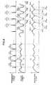
- FIG. 4is a time chart showing the relation between an impact torque T, a motor current I, and a motor rpm N.
- FIG. 5A and FIG. 5Bare flowcharts showing the control of reducing the rpm of the motor 1 before and after the impact by the hammer 12 .
- the load applied to the motor 1reaches a maximum. As shown in FIG. 4 , the rpm N of the motor 1 reaches a minimum ((A)) in the result. On the other hand, since the load applied to the motor 1 reaches a maximum, the motor current I reaches a maximum ((B)). After that, as the hammer 12 gets on the anvil projections 13 a of the anvil 13 , the load applied in the rotating direction of the motor 1 is reduced. The hammer 12 then gets over the anvil projections 13 a of the anvil 13 , to go out of the engagement with the anvil 13 ((A) and (B) of FIG. 2 ).
- the load applied to the motor 1reaches a minimum, and the rpm N of the motor 1 reaches a maximum ((C)).
- the motor current Ireaches a minimum ((D)).
- the hammer 12performs an impact motion ((E)).
- a motor having a large drive powersuch as a brushless motor
- the impact by the hammeris too strong.
- the hammergets on the anvil projections, the hammer moves backward to an excessive degree. This may cause the hammer to crash into the opposite wall, thereby breaking the wall.
- the rpm of the motor 1is reduced before and after the impact by the hammer 12 in this mode.
- the CPUdetermines whether or not the PWM duty of the motor control is 100%. This is because the hammer 12 usually moves backward to an excessive degree when the trigger switch 15 is depressed to the fullest extent, specifically, when the PWM duty cycle is 100%.
- the CPUdetermines whether or not the motor current I is 35 A or larger in S 502 . In this mode, a threshold value is set to 35 A, which may cause the hammer 12 to move backward to an excessive degree. However, another value can be employed as the threshold value.
- the CPUdetermines whether or not the motor current I is 35 A or larger. If the motor current I is 35 A or larger (S 502 : YES), the CPU starts the timer for a time period Ta (10 msec) in S 503 (see FIG. 4 ). In S 504 , the CPU determines again whether or not the motor current I is 35 A or larger.
- the CPUcounts up a CNT 1 in S 505 .
- the CPUdetermines whether or not the time period Ta (10 msec) has passed. If the motor current I is smaller than 35 A (S 504 : NO), the CPU determine whether or not the time period Ta (10 msec) has passed, without counting up the CNT 1 in S 506 . In this manner, the number of times the motor current I is equal to the threshold value 35 A or larger, is counted, detected within a predetermined period of time (10 msec in this mode).
- the CPUreturns to S 502 .
- the CPUagain determines whether or not the motor current I is 35 A or larger. If the number counted up by the CNT 1 is larger than 5 (S 508 : YES), the CPU counts up a CNT 2 in S 509 .
- the CPUdetermines whether or not the number counted up by the CNT 2 is larger than 5. If the number counted up by the CNT 2 is 5 or smaller (S 510 : NO), the CPU returns to S 502 .
- the CPUagain determines whether or not the motor current I is 35 A or larger. After the determination five times in S 508 , that the motor current I detected in S 503 to S 507 becomes equal to or exceeds the threshold value 35 A more than five times in total, the CPU starts the control of reducing the rpm of the motor 1 .
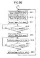
- the CPUdecides the maximum value Nmax for the motor rpm N in S 511 (see FIG. 4 ). In this mode, the CPU detects the motor rpm N per 1 msec. If a detected result is larger than the previous detected result, the CPU updates the maximum value. The CPU employs the updated value after four detection operations as the maximum value Nmax. As a result, the CPU detects the moment when the impact by the hammer 12 occurs.
- the CPUdecides a minimum value Nmin for the motor rpm N (see FIG. 4 ). In this mode, the CPU detects the motor rpm N per 1 msec. If a detected result is smaller than the previous detected result, the CPU updates the minimum value. The CPU employs the updated minimum value after four detection operations as a minimum value Nmin. As a result, the CPU detects the moment when the hammer 12 combines with the anvil projections 13 a , specifically, the moment immediately before the hammer 12 gets on the anvil projections 13 a.
- the CPUstarts the timer for a time period Tb (7 msec).
- the CPUdetermines whether or not the time period Tb (7 msec) has passed (see FIG. 4 ). If the time period Tb (7 msec) has not passed yet (S 514 : NO), the CPU continues to determine whether or not the time period Tb (7 msec) has passed.
- the time period Tb (7 msec)is not limited to 7 msec as long as the time period Tb is shorter than the time period after the moment when the hammer 12 engages with the anvil projections 13 a , until the moment the impact by the hammer 12 occurs.
- the motor 1is driven with a PWM duty cycle of 100% until the moment a little before the impact by the hammer 12 occurs.
- the CPUstarts the timer for a time period Tc (6 msec) in S 515 .
- the CPUreduces the PWM duty cycle to 70% (see FIG. 4 ).
- the time period Tc (6 msec)is not limited to 6 msec as long as the time period Tc includes the moment when the impact by the hammer 12 .
- the motor 1is driven with a PWM duty cycle of 70% before and after the moment when the impact by the hammer 12 occurs.
- the CPUdetermine whether or not the time period Tc (6 msec) has passed in S 517 (see FIG. 4 ). If the time period Tc (6 msec) has not passed yet (S 517 : NO), the CPU continues to determine whether or not the time period Tc (6 msec) has passed. If the time period Tc (6 msec) has passed (S 517 : YES), the CPU returns the PWM duty cycle to 100% in S 518 .
- This configurationreduces the PWM duty cycle of the motor control, specifically, reduces the rpm of the motor 1 , before and after the moment when the impact by the hammer 12 occurs.
- the configurationprevents the impact by the hammer 12 from being excessive, thereby preventing the hammer 12 from moving backward to an excessive degree to crash into the opposite wall.
- the PWM duty cycleis reduced when the number at which the current value exceeds a predetermined value is equal to or greater than a predetermined number, the excessive impact by the spindle can be prevented reliably from occurring.
- the PWM duty cycleis reduced after the minimum value of the motor rpm is detected, the time at which the impact occurs can be detected reliably.
- FIGS. 6 , 7 A and 7 Ba description is given for the control of an impact driver 100 according to a second mode of the present invention.
- FIG. 6are time charts showing the relation between an impact torque T, a motor current I, and a motor rpm N.
- FIGS. 7A and 7Bare flowcharts showing the control of reducing the rpm of the motor 1 before and after the impact by the hammer 12 .
- the steps which are the same as in the flowcharts of FIGS. 5A and 5Bhave the same reference numbers. A description is given only for different steps here.
- the CPUstarts the timer for a time period Tz (300 msec) in S 701 (see FIG. 6 ). After that, the CPU determines whether or not the time period Tz (300 msec) has passed in S 702 . If the time period Tz (300 msec) has not passed yet (S 702 : NO), the CPU proceeds to S 502 to perform the control described in FIGS. 5A and 5B . If the CPU determines that the number counted up by the CNT 2 is 5 or smaller in S 510 , the CPU returns to S 702 to determine whether or not the time period Tz (300 msec) has passed.
- the CPUdoes not start the control of reducing the rpm of the motor 1 within a predetermined period of time (300 msec in this mode)
- the CPUdoes not perform the control of reducing the rpm of the motor 1 later in the process, either.
- a driveris employed as the end bit
- a screwis to be tightened into a wooden board or the like. Therefore, if the rpm of the motor 1 is reduced during the screwing operation, the screw is likely not to reach the right position therefor.
- the CPUdoes not start the control of reducing the rpm of the motor 1 within the predetermined period of time, the CPU does not perform the control of reducing the rpm of the motor 1 later in the process, either. As a result, a screw is securely tightened in a wooden board or the like.
- FIGS. 8 and 9A to 9 Ca description is given for the control of an impact driver 100 according to a third mode of the present invention.
- FIG. 8are time charts showing the relation between an impact torque T, a motor current I, and a motor rpm N.
- FIG. 9A to FIG. 9Care flowcharts showing the control of reducing the rpm of the motor 1 before and after the impact by the hammer 12 .
- the steps which are the same as in the flowcharts of FIGS. 7A and 7Bhave the same reference numbers. A description is given only for different steps here.
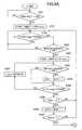
- the CPUdetermines whether or not a Tc flag meaning that the time intervals of the impact by the hammer 12 are longer and shorter alternatively, as shown in FIG. 8A is zero in S 901 . If the Tc flag is zero (S 901 : YES), the CPU determines whether or not Td_old4 ⁇ Td_old3, Td_old3>Td_old2, Td_old2 ⁇ Td_old1, and Td_old1 ⁇ Td at the same time in S 902 . In this case, the Td_old4, the Td_old3, the Td_old2, and the Td_old1 mean Tds one to four cycles before, respectively. The term Td is described later.
- Td_old4Td_old3, Td_old3>Td_old2, Td_old2 ⁇ Td_old1, and Td_old1 ⁇ Td at the same time (S 902 : YES)
- the CPUsets the Tc flag to one in S 904 . After that, the CPU decides the maximum value Nmax for the motor rpm N in S 511 . If NO in S 901 or S 902 , the CPU proceeds straight to S 511 to decide a maximum value Nmax for the motor rpm N.
- the CPUAfter deciding the maximum value Nmax for the motor rpm N in S 511 , the CPU starts the timer in S 904 . The CPU then decides a minimum value Nmin for the motor rpm N in S 512 . While deciding the minimum value Nmin for the motor rpm N, the CPU stops the timer from counting, and stores the counted value Td in S 905 . Specifically, the counted value Td means the period of time lapsed after the maximum value Nmax of the motor rpm N until the minimum value Nmin thereof. The Td thus stored is used for making the determination in S 902 .
- the CPUdetermines whether or not the Tc flag is one in S 906 . If the Tc flag is one (S 906 : YES), the CPU determines whether or not the previous value of the Tc is 4 msec in S 907 . If the previous value of the Tc is 4 msec (S 907 : YES), the CPU sets the time period Tc to 9 msec in S 908 , and then starts the timer in S 911 . On the other hand, if the previous value of the Tc is not 4 msec (S 907 : NO), the CPU sets the time period Tc to 4 msec in S 909 , and then starts the timer in S 911 .
- the CPUsets the time period Tc to 6 msec in S 910 , and then starts the timer in S 911 .
- the CPUreduces the PWM duty cycle to 70% at the same time as the timer starts in S 911 .
- the CPUdetermines whether or not the time period Tc has passed.
- the CPUcontinues to determine whether or not the time period Tc has passed. If the time period Tc has passed (S 913 : YES), the CPU returns the PWM duty cycle to 100% in S 914 . In S 915 , the CPU determines whether or not a time period Tx has passed. If the time period Tx has not passed yet (S 915 : NO), the CPU returns to S 901 to determine again whether or not the Tc flag is zero. If the time period Tx has passed (S 915 : YES), the CPU sets the Tc flag to zero in S 916 , then return to S 901 .
- the Td subsequent to the past Tdis predicted.
- the subsequent Tdis controlled to have even impact intervals. Therefore, even when the impact by the hammer 12 occurs at uneven intervals, the intervals can be corrected. This configuration prevents the impact by the hammer 12 from being excessive, thereby preventing the hammer 12 from moving backward to an excessive degree to crash into the opposite wall.
- FIG. 10is a time chart showing the relation between a motor current Ih under high load, a motor current Il under low load, and a threshold current Ith.
- FIG. 11is a flowchart showing the control of reducing the motor current I when the motor current I exceeds the threshold current Ith. In this mode, the motor current I is reduced when the motor current I exceeds the threshold current Ith, like the motor current lh under high load shown in FIG. 10 .
- the CPUdetermines whether or not the PWM duty cycle of the motor control is 100%. This is because the hammer 12 usually moves backward to an excessive degree when the trigger switch 15 is depressed to the fullest extent, specifically, when the PWM duty cycle is 100%.
- the CPUdetermines whether or not the motor current I is 35 A or larger in S 1102 . In this mode, the threshold current Ith is set to 35 A, which may cause the hammer 12 to move backward to an excessive degree. However, another value can be employed as the threshold current Ith.
- the CPUcontinues to determine whether or not the motor current I is 35 A or larger. If the motor current I is 35 A or larger (S 1102 : YES), the CPU reduces the PWM duty cycle to 85% in S 1103 . As a result, the motor 1 is driven with a PWM duty cycle of 85%.
- the CPUAfter a time interval (3 msec) as a sampling time for controlling the operation unit 31 (S 1104 ), the CPU increases the PWM duty cycle by 3% in S 1105 . In S 1106 , the CPU determine whether or not the PWM duty cycle is 100% or larger. Although the PWM duty cycle never exceeds 100% in practice, the CPU determine whether or not the PWM duty cycle is 100% or larger on calculation in the operation unit 31 .
- the CPUreturns to S 1104 . After the time interval, the CPU increases the PWM duty cycle by 3% again in S 1105 . If the PWM duty cycle is 100% or larger (S 1106 : NO), this means that the PWM duty cycle has been set to 100%. The CPU returns to S 1102 to determine again whether or not the motor current I is 35 A or larger.
- An impact tool of the present inventioncan be used to tighten a screw, a bolt, or the like, in a workplace.
Landscapes
- Engineering & Computer Science (AREA)
- Mechanical Engineering (AREA)
- Portable Power Tools In General (AREA)
Abstract
Description
- 100 impact driver
- 1 brushless direct-current motor
- 2 inverter
- 3 control circuit section
- 31 operation unit
- 32 current detection circuit
- 33 applied voltage setting circuit
- 36 rotational speed detection circuit
- 37 control signal output circuit
- 10 rotational impact system
- 11 spindle
Claims (4)
Applications Claiming Priority (5)
| Application Number | Priority Date | Filing Date | Title |
|---|---|---|---|
| JP2007246249AJP5115904B2 (en) | 2007-09-21 | 2007-09-21 | Impact tools |
| JP2007246258AJP5527569B2 (en) | 2007-09-21 | 2007-09-21 | Impact tools |
| JP2007-246249 | 2007-09-21 | ||
| JP2007-246258 | 2007-09-21 | ||
| PCT/JP2008/067578WO2009038230A1 (en) | 2007-09-21 | 2008-09-19 | Impact tool |
Publications (2)
| Publication Number | Publication Date |
|---|---|
| US20100096155A1 US20100096155A1 (en) | 2010-04-22 |
| US8074731B2true US8074731B2 (en) | 2011-12-13 |
Family
ID=40120242
Family Applications (1)
| Application Number | Title | Priority Date | Filing Date |
|---|---|---|---|
| US12/530,621Active2029-03-12US8074731B2 (en) | 2007-09-21 | 2008-09-19 | Impact tool |
Country Status (3)
| Country | Link |
|---|---|
| US (1) | US8074731B2 (en) |
| EP (1) | EP2190628B1 (en) |
| WO (1) | WO2009038230A1 (en) |
Cited By (26)
| Publication number | Priority date | Publication date | Assignee | Title |
|---|---|---|---|---|
| US20110186318A1 (en)* | 2010-02-02 | 2011-08-04 | Makita Corporation | Motor control device, electric power tool, and recording medium |
| US20130133912A1 (en)* | 2010-08-17 | 2013-05-30 | Panasonic Corporation | Rotary impact tool |
| US20130186666A1 (en)* | 2012-01-23 | 2013-07-25 | Max Co., Ltd. | Rotary tool |
| US20130333910A1 (en)* | 2009-07-29 | 2013-12-19 | Hitachi Koki Co., Ltd., | Impact tool |
| US8919456B2 (en) | 2012-06-08 | 2014-12-30 | Black & Decker Inc. | Fastener setting algorithm for drill driver |
| US9193055B2 (en) | 2012-04-13 | 2015-11-24 | Black & Decker Inc. | Electronic clutch for power tool |
| US20160121467A1 (en)* | 2014-10-31 | 2016-05-05 | Black & Decker Inc. | Impact Driver Control System |
| TWI576213B (en)* | 2015-11-10 | 2017-04-01 | 豐民金屬工業股份有限公司 | Torsion control method and device for electric impact power tool |
| US9908182B2 (en) | 2012-01-30 | 2018-03-06 | Black & Decker Inc. | Remote programming of a power tool |
| US9950417B2 (en) | 2010-03-31 | 2018-04-24 | Hitachi Koki Co., Ltd. | Power tool |
| US10131043B2 (en) | 2013-10-21 | 2018-11-20 | Milwaukee Electric Tool Corporation | Adapter for power tool devices |
| US10295990B2 (en) | 2015-05-18 | 2019-05-21 | Milwaukee Electric Tool Corporation | User interface for tool configuration and data capture |
| US10406662B2 (en) | 2015-02-27 | 2019-09-10 | Black & Decker Inc. | Impact tool with control mode |
| US10420577B2 (en) | 2014-03-31 | 2019-09-24 | Covidien Lp | Apparatus and method for tissue thickness sensing |
| US10562116B2 (en) | 2016-02-03 | 2020-02-18 | Milwaukee Electric Tool Corporation | System and methods for configuring a reciprocating saw |
| US10603770B2 (en) | 2015-05-04 | 2020-03-31 | Milwaukee Electric Tool Corporation | Adaptive impact blow detection |
| USD887806S1 (en) | 2018-04-03 | 2020-06-23 | Milwaukee Electric Tool Corporation | Jigsaw |
| US10835972B2 (en) | 2018-03-16 | 2020-11-17 | Milwaukee Electric Tool Corporation | Blade clamp for power tool |
| US11014176B2 (en) | 2018-04-03 | 2021-05-25 | Milwaukee Electric Tool Corporation | Jigsaw |
| US11014224B2 (en) | 2016-01-05 | 2021-05-25 | Milwaukee Electric Tool Corporation | Vibration reduction system and method for power tools |
| US20220200511A1 (en)* | 2020-12-18 | 2022-06-23 | Black & Decker Inc. | Impact tools and control modes |
| US20230347490A1 (en)* | 2012-11-13 | 2023-11-02 | Milwaukee Electric Tool Corporation | High-power cordless, hand-held power tool including a brushless direct current motor |
| US12044530B2 (en) | 2008-07-10 | 2024-07-23 | Black & Decker Inc. | Communication protocol for remotely controlled laser devices |
| US12318906B2 (en) | 2012-06-08 | 2025-06-03 | Black & Decker Inc. | Power tool having multiple operating modes |
| USD1090213S1 (en) | 2023-10-26 | 2025-08-26 | Snap-On Incorporated | Tool housing |
| US12440907B2 (en) | 2022-08-18 | 2025-10-14 | Milwaukee Electric Tool Corporation | Systems and methods for configuring a reciprocating saw |
Families Citing this family (34)
| Publication number | Priority date | Publication date | Assignee | Title |
|---|---|---|---|---|
| MX2012001210A (en)* | 2009-07-29 | 2012-03-26 | Hitachi Koki Kk | Impact tool. |
| EP2459348B1 (en)* | 2009-07-29 | 2018-10-24 | Koki Holdings Co., Ltd. | Impact tool |
| JP5600955B2 (en)* | 2010-02-11 | 2014-10-08 | 日立工機株式会社 | Impact tools |
| JP5483086B2 (en)* | 2010-02-22 | 2014-05-07 | 日立工機株式会社 | Impact tools |
| JP5464014B2 (en)* | 2010-03-31 | 2014-04-09 | 日立工機株式会社 | Electric tool |
| JP5545476B2 (en)* | 2010-06-08 | 2014-07-09 | 日立工機株式会社 | Electric tool |
| JP5887521B2 (en)* | 2010-08-04 | 2016-03-16 | パナソニックIpマネジメント株式会社 | Electric tool system |
| JP2012076160A (en)* | 2010-09-30 | 2012-04-19 | Hitachi Koki Co Ltd | Power tool |
| US20120234566A1 (en)* | 2010-11-30 | 2012-09-20 | Hitachi Koki Co., Ltd., | Impact tool |
| US10427277B2 (en) | 2011-04-05 | 2019-10-01 | Ingersoll-Rand Company | Impact wrench having dynamically tuned drive components and method thereof |
| JP5784473B2 (en)* | 2011-11-30 | 2015-09-24 | 株式会社マキタ | Rotating hammer tool |
| CA2800792C (en)* | 2012-01-06 | 2016-10-25 | Sears Brands, Llc | Programmable portable power tool with brushless dc motor |
| JP2013202702A (en)* | 2012-03-27 | 2013-10-07 | Hitachi Koki Co Ltd | Power tool |
| DE102012216366A1 (en)* | 2012-09-14 | 2014-03-20 | Aktiebolaget Skf | Electromechanical actuator |
| DE102012218300A1 (en)* | 2012-10-08 | 2014-04-10 | Hilti Aktiengesellschaft | Method and apparatus for operating a hand tool with a tangential impactor |
| EP2926952A4 (en)* | 2012-11-29 | 2016-08-03 | Hitachi Koki Kk | PERCUSSION TOOL |
| JP6024446B2 (en)* | 2012-12-22 | 2016-11-16 | 日立工機株式会社 | Impact tools |
| EP2948274A1 (en)* | 2013-01-24 | 2015-12-02 | Hitachi Koki Co., Ltd. | Power tool |
| CN104981325B (en)* | 2013-03-30 | 2018-08-31 | 日立工机株式会社 | Electric tool |
| JP6148609B2 (en)* | 2013-11-21 | 2017-06-14 | 株式会社マキタ | Electric tool |
| EP2921263A1 (en)* | 2014-03-17 | 2015-09-23 | HILTI Aktiengesellschaft | Load-dependent impact response detection |
| DE102015211119A1 (en)* | 2014-06-20 | 2015-12-24 | Robert Bosch Gmbh | Method for controlling an electric motor of a power tool |
| JP6587110B2 (en) | 2016-01-14 | 2019-10-09 | 工機ホールディングス株式会社 | Rotating hammer tool |
| JP6734163B2 (en)* | 2016-09-26 | 2020-08-05 | 株式会社マキタ | Electric tool |
| US11318589B2 (en)* | 2018-02-19 | 2022-05-03 | Milwaukee Electric Tool Corporation | Impact tool |
| US10987784B2 (en)* | 2018-02-23 | 2021-04-27 | Ingersoll-Rand Industrial U.S., Inc. | Cordless impact tool with brushless, sensorless, motor and drive |
| EP3894136A4 (en)* | 2018-12-10 | 2023-01-11 | Milwaukee Electric Tool Corporation | HIGH TORQUE IMPACT TOOL |
| EP3898101A4 (en)* | 2018-12-21 | 2022-11-30 | Milwaukee Electric Tool Corporation | HIGH TORQUE IMPACT TOOL |
| JP7386027B2 (en)* | 2019-09-27 | 2023-11-24 | 株式会社マキタ | rotary impact tool |
| JP7320419B2 (en) | 2019-09-27 | 2023-08-03 | 株式会社マキタ | rotary impact tool |
| ES2971454T3 (en)* | 2020-01-29 | 2024-06-05 | Atlas Copco Ind Technique Ab | Power tool adapted to perform tightening operations where torque is supplied in pulses |
| US12157208B2 (en) | 2020-02-24 | 2024-12-03 | Milwaukee Electric Tool Corporation | Impact tool |
| USD948978S1 (en) | 2020-03-17 | 2022-04-19 | Milwaukee Electric Tool Corporation | Rotary impact wrench |
| CN118819202B (en)* | 2024-09-18 | 2025-01-21 | 泰田集团股份有限公司 | Torque setting system and torque setting method for electric tool |
Citations (15)
| Publication number | Priority date | Publication date | Assignee | Title |
|---|---|---|---|---|
| US3586949A (en)* | 1968-05-23 | 1971-06-22 | Pratt And Whitney Inc | Three-phase dc motor control system |
| US4412158A (en) | 1980-02-21 | 1983-10-25 | Black & Decker Inc. | Speed control circuit for an electric power tool |
| US4513381A (en)* | 1982-06-07 | 1985-04-23 | The Singer Company | Speed regulator for power tool |
| US5245747A (en)* | 1989-09-22 | 1993-09-21 | Atlas Copco Tools Ab | Device for tightening threaded joints |
| US5463293A (en)* | 1993-01-27 | 1995-10-31 | Nec Corporation | Motor control device |
| US5526460A (en)* | 1994-04-25 | 1996-06-11 | Black & Decker Inc. | Impact wrench having speed control circuit |
| US5594306A (en)* | 1994-03-10 | 1997-01-14 | C.M.L. Costruzioni Meccaniche Liri S.R.L. | Electric motor for portable machine tools |
| US5731673A (en) | 1993-07-06 | 1998-03-24 | Black & Decker Inc. | Electrical power tool having a motor control circuit for increasing the effective torque output of the power tool |
| US6172472B1 (en)* | 1997-09-29 | 2001-01-09 | Westfalia Werkzeuggompany Gesellschaft Mit Beschrankter Haftung | Control system for a two-terminal electric motor connected to a voltage network having two lines |
| US6479958B1 (en) | 1995-01-06 | 2002-11-12 | Black & Decker Inc. | Anti-kickback and breakthrough torque control for power tool |
| JP2004322262A (en) | 2003-04-24 | 2004-11-18 | Estic Corp | Method and apparatus for controlling impact type screw tightening device |
| JP2005137134A (en) | 2003-10-30 | 2005-05-26 | Matsushita Electric Works Ltd | Power tool |
| US7112934B2 (en)* | 1993-07-06 | 2006-09-26 | Black & Decker Inc. | Electrical power tool having a motor control circuit for providing control over the torque output of the power tool |
| US7121358B2 (en)* | 1999-04-29 | 2006-10-17 | Gass Stephen F | Power tools |
| WO2006121085A1 (en) | 2005-05-12 | 2006-11-16 | Estic Corporation | Control method and device for impact screw tightening device |
Family Cites Families (1)
| Publication number | Priority date | Publication date | Assignee | Title |
|---|---|---|---|---|
| JP3780831B2 (en) | 2000-08-04 | 2006-05-31 | 日立工機株式会社 | Impact tools |
- 2008
- 2008-09-19EPEP08832319.1Apatent/EP2190628B1/enactiveActive
- 2008-09-19WOPCT/JP2008/067578patent/WO2009038230A1/enactiveApplication Filing
- 2008-09-19USUS12/530,621patent/US8074731B2/enactiveActive
Patent Citations (15)
| Publication number | Priority date | Publication date | Assignee | Title |
|---|---|---|---|---|
| US3586949A (en)* | 1968-05-23 | 1971-06-22 | Pratt And Whitney Inc | Three-phase dc motor control system |
| US4412158A (en) | 1980-02-21 | 1983-10-25 | Black & Decker Inc. | Speed control circuit for an electric power tool |
| US4513381A (en)* | 1982-06-07 | 1985-04-23 | The Singer Company | Speed regulator for power tool |
| US5245747A (en)* | 1989-09-22 | 1993-09-21 | Atlas Copco Tools Ab | Device for tightening threaded joints |
| US5463293A (en)* | 1993-01-27 | 1995-10-31 | Nec Corporation | Motor control device |
| US5731673A (en) | 1993-07-06 | 1998-03-24 | Black & Decker Inc. | Electrical power tool having a motor control circuit for increasing the effective torque output of the power tool |
| US7112934B2 (en)* | 1993-07-06 | 2006-09-26 | Black & Decker Inc. | Electrical power tool having a motor control circuit for providing control over the torque output of the power tool |
| US5594306A (en)* | 1994-03-10 | 1997-01-14 | C.M.L. Costruzioni Meccaniche Liri S.R.L. | Electric motor for portable machine tools |
| US5526460A (en)* | 1994-04-25 | 1996-06-11 | Black & Decker Inc. | Impact wrench having speed control circuit |
| US6479958B1 (en) | 1995-01-06 | 2002-11-12 | Black & Decker Inc. | Anti-kickback and breakthrough torque control for power tool |
| US6172472B1 (en)* | 1997-09-29 | 2001-01-09 | Westfalia Werkzeuggompany Gesellschaft Mit Beschrankter Haftung | Control system for a two-terminal electric motor connected to a voltage network having two lines |
| US7121358B2 (en)* | 1999-04-29 | 2006-10-17 | Gass Stephen F | Power tools |
| JP2004322262A (en) | 2003-04-24 | 2004-11-18 | Estic Corp | Method and apparatus for controlling impact type screw tightening device |
| JP2005137134A (en) | 2003-10-30 | 2005-05-26 | Matsushita Electric Works Ltd | Power tool |
| WO2006121085A1 (en) | 2005-05-12 | 2006-11-16 | Estic Corporation | Control method and device for impact screw tightening device |
Cited By (58)
| Publication number | Priority date | Publication date | Assignee | Title |
|---|---|---|---|---|
| US12044530B2 (en) | 2008-07-10 | 2024-07-23 | Black & Decker Inc. | Communication protocol for remotely controlled laser devices |
| US20130333910A1 (en)* | 2009-07-29 | 2013-12-19 | Hitachi Koki Co., Ltd., | Impact tool |
| US20110186318A1 (en)* | 2010-02-02 | 2011-08-04 | Makita Corporation | Motor control device, electric power tool, and recording medium |
| US8616299B2 (en)* | 2010-02-02 | 2013-12-31 | Makita Corporation | Motor control device, electric power tool, and recording medium |
| US9950417B2 (en) | 2010-03-31 | 2018-04-24 | Hitachi Koki Co., Ltd. | Power tool |
| US9427852B2 (en)* | 2010-08-17 | 2016-08-30 | Panasonic Intellectual Property Management Co., Ltd. | Rotary impact tool |
| US20130133912A1 (en)* | 2010-08-17 | 2013-05-30 | Panasonic Corporation | Rotary impact tool |
| US9296095B2 (en)* | 2012-01-23 | 2016-03-29 | Max Co., Ltd. | Rotary tool |
| US20130186666A1 (en)* | 2012-01-23 | 2013-07-25 | Max Co., Ltd. | Rotary tool |
| US10661355B2 (en) | 2012-01-30 | 2020-05-26 | Black & Decker Inc. | Remote programming of a power tool |
| US9908182B2 (en) | 2012-01-30 | 2018-03-06 | Black & Decker Inc. | Remote programming of a power tool |
| US11712741B2 (en) | 2012-01-30 | 2023-08-01 | Black & Decker Inc. | Remote programming of a power tool |
| US9193055B2 (en) | 2012-04-13 | 2015-11-24 | Black & Decker Inc. | Electronic clutch for power tool |
| US10220500B2 (en) | 2012-04-13 | 2019-03-05 | Black & Decker Inc. | Electronic clutch for power tool |
| US8919456B2 (en) | 2012-06-08 | 2014-12-30 | Black & Decker Inc. | Fastener setting algorithm for drill driver |
| US12318906B2 (en) | 2012-06-08 | 2025-06-03 | Black & Decker Inc. | Power tool having multiple operating modes |
| US20240075605A1 (en)* | 2012-11-13 | 2024-03-07 | Milwaukee Electric Tool Corporation | High-power cordless, hand-held power tool including a brushless direct current motor |
| US12377529B2 (en)* | 2012-11-13 | 2025-08-05 | Milwaukee Electric Tool Corporation | High-power cordless, hand-held power tool including a brushless direct current motor |
| US12370664B2 (en) | 2012-11-13 | 2025-07-29 | Milwaukee Electric Tool Corporation | High-power cordless, hand-held power tool including a brushless direct current motor |
| US12011812B2 (en)* | 2012-11-13 | 2024-06-18 | Milwaukee Electric Tool Corporation | High-power cordless, hand-held power tool including a brushless direct current motor |
| US20230347490A1 (en)* | 2012-11-13 | 2023-11-02 | Milwaukee Electric Tool Corporation | High-power cordless, hand-held power tool including a brushless direct current motor |
| US10967489B2 (en) | 2013-10-21 | 2021-04-06 | Milwaukee Electric Tool Corporation | Power tool communication system |
| US10131043B2 (en) | 2013-10-21 | 2018-11-20 | Milwaukee Electric Tool Corporation | Adapter for power tool devices |
| US10569398B2 (en) | 2013-10-21 | 2020-02-25 | Milwaukee Electric Tool Corporation | Adaptor for power tool devices |
| US12059779B2 (en) | 2013-10-21 | 2024-08-13 | Milwaukee Electric Tool Corporation | Power tool communication system |
| US11541521B2 (en) | 2013-10-21 | 2023-01-03 | Milwaukee Electric Tool Corporation | Power tool communication system |
| US11738426B2 (en) | 2013-10-21 | 2023-08-29 | Milwaukee Electric Tool Corporation | Power tool communication system |
| US10213908B2 (en) | 2013-10-21 | 2019-02-26 | Milwaukee Electric Tool Corporation | Adapter for power tool devices |
| US10131042B2 (en) | 2013-10-21 | 2018-11-20 | Milwaukee Electric Tool Corporation | Adapter for power tool devices |
| US10420577B2 (en) | 2014-03-31 | 2019-09-24 | Covidien Lp | Apparatus and method for tissue thickness sensing |
| US20160121467A1 (en)* | 2014-10-31 | 2016-05-05 | Black & Decker Inc. | Impact Driver Control System |
| US11904441B2 (en) | 2015-02-27 | 2024-02-20 | Black & Decker Inc. | Impact tool with control mode |
| US10406662B2 (en) | 2015-02-27 | 2019-09-10 | Black & Decker Inc. | Impact tool with control mode |
| US11919129B2 (en) | 2015-05-04 | 2024-03-05 | Milwaukee Electric Tool Corporation | Adaptive impact blow detection |
| US11485000B2 (en) | 2015-05-04 | 2022-11-01 | Milwaukee Electric Tool Corporation | Adaptive impact blow detection |
| US10603770B2 (en) | 2015-05-04 | 2020-03-31 | Milwaukee Electric Tool Corporation | Adaptive impact blow detection |
| US10976726B2 (en) | 2015-05-18 | 2021-04-13 | Milwaukee Electric Tool Corporation | User interface for tool configuration and data capture |
| US10838407B2 (en) | 2015-05-18 | 2020-11-17 | Milwaukee Electric Tool Corporation | User interface for tool configuration and data capture |
| US10295990B2 (en) | 2015-05-18 | 2019-05-21 | Milwaukee Electric Tool Corporation | User interface for tool configuration and data capture |
| US12248303B2 (en) | 2015-05-18 | 2025-03-11 | Milwaukee Electric Tool Corporation | User interface for tool configuration and data capture |
| US11599093B2 (en) | 2015-05-18 | 2023-03-07 | Milwaukee Electric Tool Corporation | User interface for tool configuration and data capture |
| US11256234B2 (en) | 2015-05-18 | 2022-02-22 | Milwaukee Electric Tool Corporation | User interface for tool configuration and data capture |
| US11886168B2 (en) | 2015-05-18 | 2024-01-30 | Milwaukee Electric Tool Corporation | User interface for tool configuration and data capture |
| TWI576213B (en)* | 2015-11-10 | 2017-04-01 | 豐民金屬工業股份有限公司 | Torsion control method and device for electric impact power tool |
| US11014224B2 (en) | 2016-01-05 | 2021-05-25 | Milwaukee Electric Tool Corporation | Vibration reduction system and method for power tools |
| US12179332B2 (en) | 2016-01-05 | 2024-12-31 | Milwaukee Electric Tool Corporation | Vibration reduction system and method for power tools |
| US10562116B2 (en) | 2016-02-03 | 2020-02-18 | Milwaukee Electric Tool Corporation | System and methods for configuring a reciprocating saw |
| US11433466B2 (en) | 2016-02-03 | 2022-09-06 | Milwaukee Electric Tool Corporation | System and methods for configuring a reciprocating saw |
| US10835972B2 (en) | 2018-03-16 | 2020-11-17 | Milwaukee Electric Tool Corporation | Blade clamp for power tool |
| US11014176B2 (en) | 2018-04-03 | 2021-05-25 | Milwaukee Electric Tool Corporation | Jigsaw |
| US11813682B2 (en) | 2018-04-03 | 2023-11-14 | Milwaukee Electric Tool Corporation | Jigsaw |
| USD887806S1 (en) | 2018-04-03 | 2020-06-23 | Milwaukee Electric Tool Corporation | Jigsaw |
| US12015364B2 (en)* | 2020-12-18 | 2024-06-18 | Black & Decker Inc. | Impact tools and control modes |
| US20220200511A1 (en)* | 2020-12-18 | 2022-06-23 | Black & Decker Inc. | Impact tools and control modes |
| US12212264B2 (en) | 2020-12-18 | 2025-01-28 | Black & Decker Inc. | Impact tools and control modes |
| US11855567B2 (en) | 2020-12-18 | 2023-12-26 | Black & Decker Inc. | Impact tools and control modes |
| US12440907B2 (en) | 2022-08-18 | 2025-10-14 | Milwaukee Electric Tool Corporation | Systems and methods for configuring a reciprocating saw |
| USD1090213S1 (en) | 2023-10-26 | 2025-08-26 | Snap-On Incorporated | Tool housing |
Also Published As
| Publication number | Publication date |
|---|---|
| EP2190628A1 (en) | 2010-06-02 |
| US20100096155A1 (en) | 2010-04-22 |
| EP2190628B1 (en) | 2016-03-23 |
| WO2009038230A1 (en) | 2009-03-26 |
Similar Documents
| Publication | Publication Date | Title |
|---|---|---|
| US8074731B2 (en) | Impact tool | |
| CN101641186A (en) | Impact tool | |
| JP5483086B2 (en) | Impact tools | |
| US8607892B2 (en) | Rotary striking tool | |
| JP5360344B2 (en) | Electric tool | |
| EP2407274B1 (en) | Rotary impact tool | |
| JP6032289B2 (en) | Impact tools | |
| US8360166B2 (en) | Rotary striking tool | |
| JP6024446B2 (en) | Impact tools | |
| EP2576146B1 (en) | Power tool | |
| US20130008679A1 (en) | Power Tool | |
| JP5527569B2 (en) | Impact tools | |
| US20120073846A1 (en) | Power tool | |
| US20150158157A1 (en) | Electric power tool | |
| EP2459346A1 (en) | Impact tool | |
| JP2008278633A (en) | Electric tool | |
| JP5381390B2 (en) | Electric tool | |
| JP2017213619A (en) | tool | |
| CN118769189A (en) | Impact tool and control method | |
| JP2015030063A (en) | Electric tool |
Legal Events
| Date | Code | Title | Description |
|---|---|---|---|
| AS | Assignment | Owner name:HITACHI KOKI CO., LTD.,JAPAN Free format text:ASSIGNMENT OF ASSIGNORS INTEREST;ASSIGNORS:IWATA, KAZUTAKA;WATANABE, SHINJI;TAKANO, NOBUHIRO;REEL/FRAME:023215/0272 Effective date:20090820 Owner name:HITACHI KOKI CO., LTD., JAPAN Free format text:ASSIGNMENT OF ASSIGNORS INTEREST;ASSIGNORS:IWATA, KAZUTAKA;WATANABE, SHINJI;TAKANO, NOBUHIRO;REEL/FRAME:023215/0272 Effective date:20090820 | |
| STCF | Information on status: patent grant | Free format text:PATENTED CASE | |
| FEPP | Fee payment procedure | Free format text:PAYOR NUMBER ASSIGNED (ORIGINAL EVENT CODE: ASPN); ENTITY STATUS OF PATENT OWNER: LARGE ENTITY | |
| FPAY | Fee payment | Year of fee payment:4 | |
| AS | Assignment | Owner name:KOKI HOLDINGS CO., LTD., JAPAN Free format text:CHANGE OF NAME;ASSIGNOR:HITACHI KOKI KABUSHIKI KAISHA;REEL/FRAME:047270/0107 Effective date:20180601 | |
| MAFP | Maintenance fee payment | Free format text:PAYMENT OF MAINTENANCE FEE, 8TH YEAR, LARGE ENTITY (ORIGINAL EVENT CODE: M1552); ENTITY STATUS OF PATENT OWNER: LARGE ENTITY Year of fee payment:8 | |
| MAFP | Maintenance fee payment | Free format text:PAYMENT OF MAINTENANCE FEE, 12TH YEAR, LARGE ENTITY (ORIGINAL EVENT CODE: M1553); ENTITY STATUS OF PATENT OWNER: LARGE ENTITY Year of fee payment:12 |