US8074578B2 - Linear synchronous motor power control system and methods - Google Patents
Linear synchronous motor power control system and methodsDownload PDFInfo
- Publication number
- US8074578B2 US8074578B2US11/770,701US77070107AUS8074578B2US 8074578 B2US8074578 B2US 8074578B2US 77070107 AUS77070107 AUS 77070107AUS 8074578 B2US8074578 B2US 8074578B2
- Authority
- US
- United States
- Prior art keywords
- block
- guideway
- inverters
- blocks
- lsm
- Prior art date
- Legal status (The legal status is an assumption and is not a legal conclusion. Google has not performed a legal analysis and makes no representation as to the accuracy of the status listed.)
- Active
Links
Images
Classifications
- B—PERFORMING OPERATIONS; TRANSPORTING
- B60—VEHICLES IN GENERAL
- B60L—PROPULSION OF ELECTRICALLY-PROPELLED VEHICLES; SUPPLYING ELECTRIC POWER FOR AUXILIARY EQUIPMENT OF ELECTRICALLY-PROPELLED VEHICLES; ELECTRODYNAMIC BRAKE SYSTEMS FOR VEHICLES IN GENERAL; MAGNETIC SUSPENSION OR LEVITATION FOR VEHICLES; MONITORING OPERATING VARIABLES OF ELECTRICALLY-PROPELLED VEHICLES; ELECTRIC SAFETY DEVICES FOR ELECTRICALLY-PROPELLED VEHICLES
- B60L13/00—Electric propulsion for monorail vehicles, suspension vehicles or rack railways; Magnetic suspension or levitation for vehicles
- B60L13/03—Electric propulsion by linear motors
- B—PERFORMING OPERATIONS; TRANSPORTING
- B60—VEHICLES IN GENERAL
- B60L—PROPULSION OF ELECTRICALLY-PROPELLED VEHICLES; SUPPLYING ELECTRIC POWER FOR AUXILIARY EQUIPMENT OF ELECTRICALLY-PROPELLED VEHICLES; ELECTRODYNAMIC BRAKE SYSTEMS FOR VEHICLES IN GENERAL; MAGNETIC SUSPENSION OR LEVITATION FOR VEHICLES; MONITORING OPERATING VARIABLES OF ELECTRICALLY-PROPELLED VEHICLES; ELECTRIC SAFETY DEVICES FOR ELECTRICALLY-PROPELLED VEHICLES
- B60L15/00—Methods, circuits, or devices for controlling the traction-motor speed of electrically-propelled vehicles
- B60L15/32—Control or regulation of multiple-unit electrically-propelled vehicles
- B60L15/38—Control or regulation of multiple-unit electrically-propelled vehicles with automatic control
- B—PERFORMING OPERATIONS; TRANSPORTING
- B66—HOISTING; LIFTING; HAULING
- B66B—ELEVATORS; ESCALATORS OR MOVING WALKWAYS
- B66B11/00—Main component parts of lifts in, or associated with, buildings or other structures
- B66B11/04—Driving gear ; Details thereof, e.g. seals
- B66B11/0407—Driving gear ; Details thereof, e.g. seals actuated by an electrical linear motor
- B—PERFORMING OPERATIONS; TRANSPORTING
- B60—VEHICLES IN GENERAL
- B60L—PROPULSION OF ELECTRICALLY-PROPELLED VEHICLES; SUPPLYING ELECTRIC POWER FOR AUXILIARY EQUIPMENT OF ELECTRICALLY-PROPELLED VEHICLES; ELECTRODYNAMIC BRAKE SYSTEMS FOR VEHICLES IN GENERAL; MAGNETIC SUSPENSION OR LEVITATION FOR VEHICLES; MONITORING OPERATING VARIABLES OF ELECTRICALLY-PROPELLED VEHICLES; ELECTRIC SAFETY DEVICES FOR ELECTRICALLY-PROPELLED VEHICLES
- B60L2200/00—Type of vehicles
- B60L2200/26—Rail vehicles
- B—PERFORMING OPERATIONS; TRANSPORTING
- B60—VEHICLES IN GENERAL
- B60L—PROPULSION OF ELECTRICALLY-PROPELLED VEHICLES; SUPPLYING ELECTRIC POWER FOR AUXILIARY EQUIPMENT OF ELECTRICALLY-PROPELLED VEHICLES; ELECTRODYNAMIC BRAKE SYSTEMS FOR VEHICLES IN GENERAL; MAGNETIC SUSPENSION OR LEVITATION FOR VEHICLES; MONITORING OPERATING VARIABLES OF ELECTRICALLY-PROPELLED VEHICLES; ELECTRIC SAFETY DEVICES FOR ELECTRICALLY-PROPELLED VEHICLES
- B60L2220/00—Electrical machine types; Structures or applications thereof
- B60L2220/10—Electrical machine types
- B60L2220/14—Synchronous machines
Definitions
- the inventionpertains to guideway operated vehicular systems and, more particularly, to improved methods and apparatus for controlling and propelling vehicles utilizing linear synchronous motors.
- the inventionhas application in people movers and materials transport systems, to name but a few.
- LSMLinear Synchronous Motor
- the type of LSM most appropriate for these missionsis the “long stator” version in which the stator, or primary, runs the entire length of the guideway and the vehicle, or secondary, is much shorter and moves in close proximity to the stator.
- blocksregions that are typically referred to as “blocks” and to provide a separate power control system for each block.
- Such a power control systemtypically includes a power source (in the case of an LSM, a variable frequency, variable voltage, multi-phase source) and a controller (microprocessor-based or otherwise) with position sensing, e.g., to adjust the inverter to insure proper vehicle operation.
- a power sourcein the case of an LSM, a variable frequency, variable voltage, multi-phase source
- a controllermicroprocessor-based or otherwise with position sensing, e.g., to adjust the inverter to insure proper vehicle operation.
- the power control system of an LSMis referred to as an “inverter.”
- a common prior art configuration of the power control system of an LSMis to have a separate inverter for each block.
- An example of an implementation of this power control schemeis shown in U.S. Pat. No. 3,158,765, Magnetic system of transportation. That patent shows a power control scheme that is similar to FIG. 1 hereof.
- the inverter for that blockis activated (e.g., by the associated controller) for powering the moving vehicle while it is within that block.
- Simple block switching of this typeis satisfactory if the vehicles are not too close and the power dissipation in the stator is not too large.
- a problem with sub-block switchingis that it does not permit propulsion and control of multiple vehicles which are closely spaced.
- itis not suitable for elevator applications of the LSM where two or more cabs operate in the same hoistway and have to move independently, even stopping on adjacent floors anywhere in a building.
- itis it suitable for transit system applications, where it is desirable to have short spacing between vehicles in and near stations. In instances such as these, it is not necessary to have close spacing everywhere along the guideway, however, such need does exist at specific locations.
- An object of the inventionis to provide improved linear synchronous control systems and methods.
- a further object of the inventionis to provide such systems and methods for use in guideway operated vehicles.
- a still further object of the inventionis to provide such systems and methods as permit independent powering and/or control of closely spaced vehicles—even in instances where multiple vehicles are in a single block.
- a related object of the inventionis to provide such systems and methods as can also be used where vehicles are not so closely spaced.
- the inventionprovides, in some aspects, a power control system and method for use with LSM propulsion that uses overlapping blocks so as allow closely spaced vehicles without the need for short blocks.
- a power control systemcan be used in conjunction with other control schemes to permit propulsion and control of closely-spaced vehicles in designated regions of the guideway, e.g., in and near stations. In or other regions of the guideway, other control schemes can be used.
- Systems and methods according to the inventioncombine advantages of both simple block switching and sub-block switching
- the inventionprovides, in some aspects, power control systems and methods for use with LSM propulsion in which multiple inverters are switchably coupled to a common region of a guideway. That region may comprise a block or a portion thereof and, as a result of the switchable coupling, permits the inverters to propel and control multiple respective vehicles within that block.
- first and second invertersare at least switchably coupled to respective ones of first and second adjacent blocks of the guideway.
- a common region of at least the first blockis switchably coupled to both inverters. That common region, according to still further related aspects of the invention, is disposed substantially adjacent to the second block.
- Still other aspects of the inventionprovide such systems and methods in which first and second vehicles that are concurrently disposed with the first block are concurrently propelled and controlled by the first and second inverters, respectively.
- aspects of the inventionprovide a guideway for LSM propulsion of multiple vehicles having a power control system as described above. Still further aspects provide such a guideway in which the first, second and/or other inverters are coupled to regions of the guideway other than the aforesaid common region, for propelling and controlling vehicles thereon in accord with any of simple block and sub-block switching schemes.
- Yet still other aspects of the inventionprovide methods of operating a LSM paralleling the operations described above.
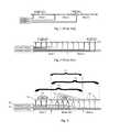
- FIG. 1shows a simple block switching scheme of the type known in the art in which there is a separate inverter for each block.
- FIG. 2shows a sub-block switching scheme of the type known in the art in which only those stator segments that can create propulsive force are energized but the blocks are significantly longer than the vehicles.
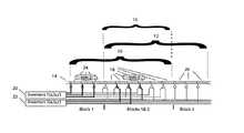
- FIG. 3shows the use of sub-block switching scheme with overlapping blocks according to the invention that allow close vehicle spacing.
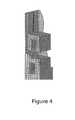
- FIG. 4shows an example of two LSM propelled elevators operating in close proximity in a single hoistway utilizing a sub-block switching scheme with overlapping blocks according to the invention.
- FIGS. 1-2describe existing prior art technology
- FIGS. 3-4illustrate LSM power control schemes and applications in accord with the invention.
- FIG. 1assume the vehicles are moving left to right with the block length greater than the vehicle length.
- Vehicle 2is entirely in Block 1 so that the entire propulsive force is provided by the stators in Block 1 .
- Vehicle 1is making a transition from Block 2 to Block 3 so both of these blocks are excited.
- Vehicle 1must move completely out of Block 2 before Vehicle 2 can enter it.
- This schemeinvolves either many blocks with a high expense for inverters or fewer blocks with more power dissipation and heating of the stators. It is a good system when vehicle velocity is high, vehicle spacing is not too close and stator heating is not a major problem. It is also a good system where the power levels are low and inverter cost is not a major consideration.
- FIG. 2there are only 2 blocks, but each block is divided into sub-blocks so as to reduce stator heating and power loss.
- One-way switchesindicated by circles with a control line running through them, determine whether an inverter is connected to a sub-block. In the drawing the heavier lines and circles with lines through them are carrying current and the lighter lines and empty circles are not carrying current.
- a vehiclecan move in a block in which another vehicle is in a different sub-block and is stationary, but two vehicles can not move independently in the same block. Hence Vehicle 1 must leave Block 2 before Vehicle 2 can enter it and thus the block length is limited by headway constraints.
- This schemeis advantageous for moving vehicles up a steep hill or vertically if the spacing between them does not have to be too small
- the vehiclemay be short compared to the length of a sub-block length with only 2 inverters per block, while in other cases the vehicle may be long compared to the length of the sub-block and more than 2 inverters used. In some cases it may not be necessary to have powered stators under the entire vehicle and this may reduce the number of inverters required.
- sub-block switchingknown variously as short-circuit, leap-frog, triplex, etc. They all achieve the same result with certain relative advantages and disadvantages.
- FIG. 3there are shown two adjacent blocks 10 (“Block 1 ”), 12 (“Block 2 ”) on guideway 14 that have a region of overlap 16 (or “common” region).
- Two-way switches, indicated by circles with a two control lines running through them, on the overlapped stators that make up the sub-blocks 18 of region 16allow each sub-block 18 to be electrically coupled to either of two inverters 20 , 22 .
- Inverter 20is further coupled to the sub-blocks 24 that comprise the remainder of block 10 via one-way switches indicated by circles with single control lines running through them.
- Inverter 22is likewise further coupled to sub-blocks 26 that comprise the remainder of block 12 via one-way switches, as shown.
- Inverters 20 , 22 and/or still other invertersmay be coupled to still other blocks that make up guideway 14 utilizing the power control scheme shown in FIG. 3 , the simple block scheme of FIG. 1 , the sub-block scheme of FIG. 2 , or otherwise.
- Guideway 14is of the type generally known in the art of LSM guideways—as adapted in accord with the teachings hereof.
- Inverters 20 , 22are of the type known in the art as typically used, for example, in a sub-block switching scheme.
- the aforesaid one-way switchesare of the type generally known in the art and shown, for example, in FIG. 2 .
- the aforesaid two-way switchesare adapted therefrom in such manner as evident to those of ordinary skill in the art.
- This power control scheme illustrated in FIG. 3allows the two vehicles, labeled “Veh 1 ”, “Veh 2 ” (which may comprise people movers, material movers or other transports of the type known in the art bearing LSM secondaries), to be very close without having short blocks. Note that both vehicles can operate at the same time in the region where Blocks 1 and 2 overlap.
- the disadvantageis the need for a two-way switch which costs more than a one-way switch but is significantly less expensive than the use of short blocks with many inverters. In many cases, such as shown in FIG. 3 , the overlapping regions of the blocks do not have to be too long if there are only certain locations where the vehicles must operate in close proximity.
- FIG. 4shows an example of two elevator cabs operating in close proximity in a single guideway—or, as such is more typically called in the case of elevators, a “hoistway.”
- This FIG.shows a single flat LSM propelling the elevator but there can be two or more LSMs, such as one on each of two sides of the cab, and the LSM could be double-sided, tubular, or any other type that has particular advantages for this application.
- the illustrated hereinare just embodiments of the invention and that other embodiments, incorporating changes thereto, fall within the scope of the invention.
- the vehicles propelled along guideway 14 of FIG. 3may be of single-car, multi-car or other configurations.
- the common regions 16may be coupled to additional inverters (e.g., by three- or more-way switches) consistent with the teachings hereof.
Landscapes
- Engineering & Computer Science (AREA)
- Mechanical Engineering (AREA)
- Power Engineering (AREA)
- Transportation (AREA)
- Civil Engineering (AREA)
- Structural Engineering (AREA)
- Physics & Mathematics (AREA)
- Electromagnetism (AREA)
- Control Of Vehicles With Linear Motors And Vehicles That Are Magnetically Levitated (AREA)
- Control Of Linear Motors (AREA)
- Linear Motors (AREA)
Abstract
Description
Claims (10)
Priority Applications (2)
| Application Number | Priority Date | Filing Date | Title |
|---|---|---|---|
| US11/770,701US8074578B2 (en) | 2006-07-05 | 2007-06-28 | Linear synchronous motor power control system and methods |
| PCT/US2007/015347WO2008005428A2 (en) | 2006-07-05 | 2007-07-02 | Linear synchronous motor power control system and methods |
Applications Claiming Priority (2)
| Application Number | Priority Date | Filing Date | Title |
|---|---|---|---|
| US81869706P | 2006-07-05 | 2006-07-05 | |
| US11/770,701US8074578B2 (en) | 2006-07-05 | 2007-06-28 | Linear synchronous motor power control system and methods |
Publications (2)
| Publication Number | Publication Date |
|---|---|
| US20080006172A1 US20080006172A1 (en) | 2008-01-10 |
| US8074578B2true US8074578B2 (en) | 2011-12-13 |
Family
ID=38895179
Family Applications (1)
| Application Number | Title | Priority Date | Filing Date |
|---|---|---|---|
| US11/770,701ActiveUS8074578B2 (en) | 2006-07-05 | 2007-06-28 | Linear synchronous motor power control system and methods |
Country Status (2)
| Country | Link |
|---|---|
| US (1) | US8074578B2 (en) |
| WO (1) | WO2008005428A2 (en) |
Cited By (26)
| Publication number | Priority date | Publication date | Assignee | Title |
|---|---|---|---|---|
| US20100276255A1 (en)* | 2009-03-03 | 2010-11-04 | ATS Automotion Tooling Systems Inc. | Multi-mode scroll cam conveyor system |
| US8840848B2 (en) | 2010-07-23 | 2014-09-23 | Beckman Coulter, Inc. | System and method including analytical units |
| US8973736B2 (en) | 2011-11-07 | 2015-03-10 | Beckman Coulter, Inc. | Magnetic damping for specimen transport system |
| US9046506B2 (en) | 2011-11-07 | 2015-06-02 | Beckman Coulter, Inc. | Specimen container detection |
| US9248982B2 (en) | 2011-05-13 | 2016-02-02 | Beckman Coulter, Inc. | System and method including laboratory product transport element |
| US9346371B2 (en) | 2009-01-23 | 2016-05-24 | Magnemotion, Inc. | Transport system powered by short block linear synchronous motors |
| US9446418B2 (en) | 2011-11-07 | 2016-09-20 | Beckman Coulter, Inc. | Robotic arm |
| US9459273B2 (en) | 2011-05-13 | 2016-10-04 | Beckman Coulter, Inc. | Laboratory product transport element and path arrangement |
| US9482684B2 (en) | 2011-11-07 | 2016-11-01 | Beckman Coulter, Inc. | Centrifuge system and workflow |
| US9506943B2 (en) | 2011-11-07 | 2016-11-29 | Beckman Coulter, Inc. | Aliquotter system and workflow |
| US9588038B2 (en) | 2012-09-14 | 2017-03-07 | Beckman Coulter, Inc. | Analytical system with capillary transport |
| US9771000B2 (en) | 2009-01-23 | 2017-09-26 | Magnemotion, Inc. | Short block linear synchronous motors and switching mechanisms |
| US9802507B2 (en) | 2013-09-21 | 2017-10-31 | Magnemotion, Inc. | Linear motor transport for packaging and other uses |
| US9910054B2 (en) | 2011-11-07 | 2018-03-06 | Beckman Coulter, Inc. | System and method for processing samples |
| US10427162B2 (en) | 2016-12-21 | 2019-10-01 | Quandx Inc. | Systems and methods for molecular diagnostics |
| US10558201B2 (en) | 2016-09-09 | 2020-02-11 | The Procter & Gamble Company | System and method for producing products based upon demand |
| US10613523B2 (en) | 2016-09-09 | 2020-04-07 | The Procter & Gamble Company | Methods for simultaneously producing different products on a single production line |
| US10643875B2 (en) | 2016-09-09 | 2020-05-05 | The Procter & Gamble Company | System and method for simultaneously filling containers with different fluent compositions |
| US10640354B2 (en) | 2016-09-09 | 2020-05-05 | The Procter & Gamble Company | System and method for simultaneously filling containers of different shapes and/or sizes |
| US10640249B2 (en) | 2016-09-09 | 2020-05-05 | The Procter & Gamble Company | Track system for creating finished products |
| US10647543B2 (en)* | 2015-02-05 | 2020-05-12 | Otis Elevator Company | Multi-car elevator control |
| US10843880B2 (en) | 2016-10-05 | 2020-11-24 | Laitram, L.L.C. | Linear-motor conveyor system |
| US10996232B2 (en) | 2016-09-09 | 2021-05-04 | The Procter & Gamble Company | System and method for independently routing container-loaded vehicles to create different finished products |
| US11273944B2 (en) | 2019-08-29 | 2022-03-15 | JLS Automation | Adaptive container loading assembly |
| US11401119B2 (en) | 2017-06-19 | 2022-08-02 | Laitram, L.L.C. | Monorail tray conveyor |
| US11584628B2 (en) | 2016-09-09 | 2023-02-21 | The Procter & Gamble Company | System and method for independently routing vehicles and delivering containers and closures to unit operation systems |
Families Citing this family (17)
| Publication number | Priority date | Publication date | Assignee | Title |
|---|---|---|---|---|
| IT1398608B1 (en) | 2010-03-09 | 2013-03-08 | Ima Life S R L Unipersonale | TRANSPORT APPARATUS |
| GB2496436A (en)* | 2011-11-10 | 2013-05-15 | Bombardier Transp Gmbh | Inductively transferring energy to an electric vehicle |
| EP3077316A4 (en)* | 2013-12-05 | 2017-09-13 | Otis Elevator Company | Motor drive for linear machines with distributed windings |
| JP6313642B2 (en) | 2014-04-18 | 2018-04-18 | キヤノン株式会社 | Linear motor control device and linear motor control system |
| DE102014119352A1 (en)* | 2014-12-22 | 2016-06-23 | Weber Maschinenbau Gmbh Breidenbach | MOTION DEVICE WITH OPERATING AND MAINTENANCE CONFIGURATION |
| KR20180043805A (en)* | 2015-08-24 | 2018-04-30 | 오티스 엘리베이터 컴파니 | Elevator control system |
| EP3447904B1 (en)* | 2017-08-21 | 2024-03-20 | B&R Industrial Automation GmbH | Control of long stator linear motor coils of a long stator linear motor stator |
| US10562715B2 (en) | 2017-09-12 | 2020-02-18 | Magnemotion, Inc. | Method and apparatus to diagnose a linear synchronous motor system |
| US11165372B2 (en) | 2017-09-13 | 2021-11-02 | Rockwell Automation Technologies, Inc. | Method and apparatus to characterize loads in a linear synchronous motor system |
| US10432117B1 (en) | 2018-06-22 | 2019-10-01 | Rockwell Automation Technologies, Inc. | System and method for monitoring mover status in an independent cart system |
| US10717365B2 (en) | 2018-07-13 | 2020-07-21 | Rockwell Automation Technologies, Inc. | System and method for limiting motion in an independent cart system |
| US10967892B2 (en) | 2018-11-08 | 2021-04-06 | Rockwell Automation Technologies, Inc. | Independent cart system and method of operating the same |
| US10914620B2 (en) | 2018-11-27 | 2021-02-09 | Rockwell Automation Technologies, Inc. | System and method for automatic runtime position sensor gain calibration in a linear motion system |
| EP3659852A1 (en)* | 2018-11-27 | 2020-06-03 | ENGIE Electroproject B.V. | Electric multi-mode drive system and method for operating the same, a track and a vehicle for use in such a drive system |
| US11027615B2 (en)* | 2018-11-29 | 2021-06-08 | Rockwell Automation Technologies, Inc. | System and method for improving travel across joints in a track for a linear motion system |
| US11117471B2 (en) | 2018-11-30 | 2021-09-14 | Rockwell Automation Technologies, Inc. | System and method for collision prevention in a linear motion system |
| BE1028113B1 (en)* | 2020-03-02 | 2021-09-27 | Thyssenkrupp Elevator Innovation And Operations Ag | Elevator system |
Citations (12)
| Publication number | Priority date | Publication date | Assignee | Title |
|---|---|---|---|---|
| US3158765A (en) | 1958-08-27 | 1964-11-24 | Gen Electric Co Ltd | Magnetic system of transportation |
| US3706922A (en) | 1970-06-11 | 1972-12-19 | Tokyo Shibaura Electric Co | Linear comb-shaped synchronous motor |
| US4068152A (en)* | 1972-03-08 | 1978-01-10 | Hitachi, Ltd. | Power supply system for a linear motor |
| US4348618A (en)* | 1979-03-28 | 1982-09-07 | Hitachi, Ltd. | Feeding system for linear motor type transporting system |
| US4454457A (en)* | 1981-06-19 | 1984-06-12 | Hitachi, Ltd. | Power supply system for a linear motor |
| US4955303A (en) | 1988-03-30 | 1990-09-11 | Railway Technical Research Institute | Linear motor feeder system |
| US5361707A (en)* | 1992-04-24 | 1994-11-08 | Railway Technical Research Institute | Multiple feeder system of feeder sections for feeding ground coils of superconductive magnetically levitated railway |
| US5628252A (en)* | 1993-06-17 | 1997-05-13 | Power Superconductor Applications Co. | Method and apparatus for combined levitation and guidance along guideway curvature in electrodynamic magnetically levitated high speed vehicle |
| US5839567A (en) | 1995-04-20 | 1998-11-24 | Daifuku Co., Ltd. | Conveying system |
| US5904101A (en)* | 1997-04-22 | 1999-05-18 | Power Superconductor Applications Co., Inc. | Auxiliary propulsion for magnetically levitated vehicle |
| US5929541A (en)* | 1996-11-26 | 1999-07-27 | Kinsiro Naito | Synchronous machine |
| US6236124B1 (en)* | 1998-05-01 | 2001-05-22 | Nisso Electric Corporation | Linear motor |
- 2007
- 2007-06-28USUS11/770,701patent/US8074578B2/enactiveActive
- 2007-07-02WOPCT/US2007/015347patent/WO2008005428A2/enactiveApplication Filing
Patent Citations (12)
| Publication number | Priority date | Publication date | Assignee | Title |
|---|---|---|---|---|
| US3158765A (en) | 1958-08-27 | 1964-11-24 | Gen Electric Co Ltd | Magnetic system of transportation |
| US3706922A (en) | 1970-06-11 | 1972-12-19 | Tokyo Shibaura Electric Co | Linear comb-shaped synchronous motor |
| US4068152A (en)* | 1972-03-08 | 1978-01-10 | Hitachi, Ltd. | Power supply system for a linear motor |
| US4348618A (en)* | 1979-03-28 | 1982-09-07 | Hitachi, Ltd. | Feeding system for linear motor type transporting system |
| US4454457A (en)* | 1981-06-19 | 1984-06-12 | Hitachi, Ltd. | Power supply system for a linear motor |
| US4955303A (en) | 1988-03-30 | 1990-09-11 | Railway Technical Research Institute | Linear motor feeder system |
| US5361707A (en)* | 1992-04-24 | 1994-11-08 | Railway Technical Research Institute | Multiple feeder system of feeder sections for feeding ground coils of superconductive magnetically levitated railway |
| US5628252A (en)* | 1993-06-17 | 1997-05-13 | Power Superconductor Applications Co. | Method and apparatus for combined levitation and guidance along guideway curvature in electrodynamic magnetically levitated high speed vehicle |
| US5839567A (en) | 1995-04-20 | 1998-11-24 | Daifuku Co., Ltd. | Conveying system |
| US5929541A (en)* | 1996-11-26 | 1999-07-27 | Kinsiro Naito | Synchronous machine |
| US5904101A (en)* | 1997-04-22 | 1999-05-18 | Power Superconductor Applications Co., Inc. | Auxiliary propulsion for magnetically levitated vehicle |
| US6236124B1 (en)* | 1998-05-01 | 2001-05-22 | Nisso Electric Corporation | Linear motor |
Cited By (46)
| Publication number | Priority date | Publication date | Assignee | Title |
|---|---|---|---|---|
| US10112777B2 (en) | 2009-01-23 | 2018-10-30 | Magnemotion, Inc. | Transport system powered by short block linear synchronous motors |
| US9346371B2 (en) | 2009-01-23 | 2016-05-24 | Magnemotion, Inc. | Transport system powered by short block linear synchronous motors |
| US9771000B2 (en) | 2009-01-23 | 2017-09-26 | Magnemotion, Inc. | Short block linear synchronous motors and switching mechanisms |
| US20100276255A1 (en)* | 2009-03-03 | 2010-11-04 | ATS Automotion Tooling Systems Inc. | Multi-mode scroll cam conveyor system |
| US9096386B2 (en) | 2009-03-03 | 2015-08-04 | Ats Automation Tooling Systems Inc. | Multi-mode scroll cam conveyor system |
| US8956570B2 (en) | 2010-07-23 | 2015-02-17 | Beckman Coulter, Inc. | System and method including analytical units |
| US8996320B2 (en) | 2010-07-23 | 2015-03-31 | Beckman Coulter, Inc. | System and method including analytical units |
| US8962308B2 (en) | 2010-07-23 | 2015-02-24 | Beckman Coulter, Inc. | System and method including thermal cycler modules |
| US9046455B2 (en) | 2010-07-23 | 2015-06-02 | Beckman Coulter, Inc. | System and method including multiple processing lanes executing processing protocols |
| US9519000B2 (en) | 2010-07-23 | 2016-12-13 | Beckman Coulter, Inc. | Reagent cartridge |
| US9140715B2 (en) | 2010-07-23 | 2015-09-22 | Beckman Coulter, Inc. | System and method for controlling thermal cycler modules |
| US8932541B2 (en) | 2010-07-23 | 2015-01-13 | Beckman Coulter, Inc. | Pipettor including compliant coupling |
| US9274132B2 (en) | 2010-07-23 | 2016-03-01 | Beckman Coulter, Inc. | Assay cartridge with reaction well |
| US9285382B2 (en) | 2010-07-23 | 2016-03-15 | Beckman Coulter, Inc. | Reaction vessel |
| US8840848B2 (en) | 2010-07-23 | 2014-09-23 | Beckman Coulter, Inc. | System and method including analytical units |
| US9248982B2 (en) | 2011-05-13 | 2016-02-02 | Beckman Coulter, Inc. | System and method including laboratory product transport element |
| US9658239B2 (en) | 2011-05-13 | 2017-05-23 | Beckman Coulter, Inc. | Laboratory product transport element and path arrangement |
| US10473676B2 (en) | 2011-05-13 | 2019-11-12 | Beckman Coulter, Inc. | Laboratory product transport element and path arrangement |
| US9459273B2 (en) | 2011-05-13 | 2016-10-04 | Beckman Coulter, Inc. | Laboratory product transport element and path arrangement |
| US9046506B2 (en) | 2011-11-07 | 2015-06-02 | Beckman Coulter, Inc. | Specimen container detection |
| US9446418B2 (en) | 2011-11-07 | 2016-09-20 | Beckman Coulter, Inc. | Robotic arm |
| US9506943B2 (en) | 2011-11-07 | 2016-11-29 | Beckman Coulter, Inc. | Aliquotter system and workflow |
| US9910054B2 (en) | 2011-11-07 | 2018-03-06 | Beckman Coulter, Inc. | System and method for processing samples |
| US10048284B2 (en) | 2011-11-07 | 2018-08-14 | Beckman Coulter, Inc. | Sample container cap with centrifugation status indicator device |
| US8973736B2 (en) | 2011-11-07 | 2015-03-10 | Beckman Coulter, Inc. | Magnetic damping for specimen transport system |
| US10274505B2 (en) | 2011-11-07 | 2019-04-30 | Beckman Coulter, Inc. | Robotic arm |
| US9482684B2 (en) | 2011-11-07 | 2016-11-01 | Beckman Coulter, Inc. | Centrifuge system and workflow |
| US9588038B2 (en) | 2012-09-14 | 2017-03-07 | Beckman Coulter, Inc. | Analytical system with capillary transport |
| US9802507B2 (en) | 2013-09-21 | 2017-10-31 | Magnemotion, Inc. | Linear motor transport for packaging and other uses |
| US10647543B2 (en)* | 2015-02-05 | 2020-05-12 | Otis Elevator Company | Multi-car elevator control |
| US10558201B2 (en) | 2016-09-09 | 2020-02-11 | The Procter & Gamble Company | System and method for producing products based upon demand |
| US10996232B2 (en) | 2016-09-09 | 2021-05-04 | The Procter & Gamble Company | System and method for independently routing container-loaded vehicles to create different finished products |
| US10643875B2 (en) | 2016-09-09 | 2020-05-05 | The Procter & Gamble Company | System and method for simultaneously filling containers with different fluent compositions |
| US10640354B2 (en) | 2016-09-09 | 2020-05-05 | The Procter & Gamble Company | System and method for simultaneously filling containers of different shapes and/or sizes |
| US10640249B2 (en) | 2016-09-09 | 2020-05-05 | The Procter & Gamble Company | Track system for creating finished products |
| US12060254B2 (en) | 2016-09-09 | 2024-08-13 | The Procter & Gamble Company | System and method for independently routing vehicles and delivering containers and closures to unit operation systems |
| US11698626B2 (en) | 2016-09-09 | 2023-07-11 | The Procter & Gamble Company | System and method for producing products based upon demand |
| US10613523B2 (en) | 2016-09-09 | 2020-04-07 | The Procter & Gamble Company | Methods for simultaneously producing different products on a single production line |
| US11048243B2 (en) | 2016-09-09 | 2021-06-29 | The Procter & Gamble Company | Method for producing different products on a single production line |
| US11584628B2 (en) | 2016-09-09 | 2023-02-21 | The Procter & Gamble Company | System and method for independently routing vehicles and delivering containers and closures to unit operation systems |
| US11198568B2 (en) | 2016-10-05 | 2021-12-14 | Laitram, L.L.C. | Linear-motor conveyor system |
| US10843880B2 (en) | 2016-10-05 | 2020-11-24 | Laitram, L.L.C. | Linear-motor conveyor system |
| US10427162B2 (en) | 2016-12-21 | 2019-10-01 | Quandx Inc. | Systems and methods for molecular diagnostics |
| US11401119B2 (en) | 2017-06-19 | 2022-08-02 | Laitram, L.L.C. | Monorail tray conveyor |
| US11273944B2 (en) | 2019-08-29 | 2022-03-15 | JLS Automation | Adaptive container loading assembly |
| US11884438B2 (en) | 2019-08-29 | 2024-01-30 | JLS Automation | Adaptive container loading assembly |
Also Published As
| Publication number | Publication date |
|---|---|
| WO2008005428A3 (en) | 2008-11-06 |
| WO2008005428A2 (en) | 2008-01-10 |
| US20080006172A1 (en) | 2008-01-10 |
Similar Documents
| Publication | Publication Date | Title |
|---|---|---|
| US8074578B2 (en) | Linear synchronous motor power control system and methods | |
| US4068152A (en) | Power supply system for a linear motor | |
| CN113302079B (en) | Electric multi-mode drive system and operation method thereof, track and vehicle using the drive system | |
| CN101528501B (en) | Magnetic levitation vehicle comprising at least one magnetic system | |
| CN100554029C (en) | Linear Induction Motor Traction Vehicles | |
| JPS6243406B2 (en) | ||
| SE533981C2 (en) | A system adapted for one or more electrically propelled vehicles (Contact means) | |
| US5778796A (en) | Switch system for personal rapid transit | |
| US20060096495A1 (en) | Arrangement having at least one long-stator linear motor, for operating magnetically levitated vehicles | |
| JPH0522809A (en) | Superconducting magnetic levitation railroad and power supply system therefor | |
| CN109910630A (en) | Maglev logistics vehicle applied to underground pipe gallery logistics system | |
| JP2017532936A (en) | Levitation control system for transport system | |
| US20240055967A1 (en) | Self guided linear induction motor system and method | |
| JPS6067326A (en) | electromagnetic propulsion device | |
| KR101314856B1 (en) | Rail vehicle to transport magnetic levitation train | |
| CN211075552U (en) | Unmanned modular high-speed magnetic suspension rail transit system | |
| CA2408790A1 (en) | Transportation system with linear switched reluctance actuator for propulsion and levitation | |
| EP2769875B1 (en) | Electrically powered transportation system | |
| NL2024290B1 (en) | Transport system as well as guide and shuttle in, of or for said transport system | |
| JP4074815B2 (en) | Linear Synchronous Motor Vehicle Feeding System | |
| KR100615551B1 (en) | Linear Motor Carrier with Swivel | |
| EP3798043A1 (en) | Magnetic levitation train system with an asymmetrical power distribution | |
| JPH06311609A (en) | Levitation transfer system | |
| JPS6399702A (en) | Conveyance device | |
| JP3424451B2 (en) | Low-press type elevator |
Legal Events
| Date | Code | Title | Description |
|---|---|---|---|
| AS | Assignment | Owner name:MAGNEMOTION, INC., MASSACHUSETTS Free format text:ASSIGNMENT OF ASSIGNORS INTEREST;ASSIGNOR:THORNTON, RICHARD D.;REEL/FRAME:019780/0877 Effective date:20070814 | |
| STCF | Information on status: patent grant | Free format text:PATENTED CASE | |
| REMI | Maintenance fee reminder mailed | ||
| FEPP | Fee payment procedure | Free format text:PAT HOLDER NO LONGER CLAIMS SMALL ENTITY STATUS, ENTITY STATUS SET TO UNDISCOUNTED (ORIGINAL EVENT CODE: STOL); ENTITY STATUS OF PATENT OWNER: LARGE ENTITY | |
| FPAY | Fee payment | Year of fee payment:4 | |
| SULP | Surcharge for late payment | ||
| MAFP | Maintenance fee payment | Free format text:PAYMENT OF MAINTENANCE FEE, 8TH YEAR, LARGE ENTITY (ORIGINAL EVENT CODE: M1552); ENTITY STATUS OF PATENT OWNER: LARGE ENTITY Year of fee payment:8 | |
| AS | Assignment | Owner name:ROCKWELL AUTOMATION, INC., WISCONSIN Free format text:MERGER;ASSIGNOR:MAGNEMOTION, INC.;REEL/FRAME:056745/0501 Effective date:20191220 | |
| MAFP | Maintenance fee payment | Free format text:PAYMENT OF MAINTENANCE FEE, 12TH YEAR, LARGE ENTITY (ORIGINAL EVENT CODE: M1553); ENTITY STATUS OF PATENT OWNER: LARGE ENTITY Year of fee payment:12 |