US8074440B2 - Gas turbine engine with axial movable fan variable area nozzle - Google Patents
Gas turbine engine with axial movable fan variable area nozzleDownload PDFInfo
- Publication number
- US8074440B2 US8074440B2US11/843,675US84367507AUS8074440B2US 8074440 B2US8074440 B2US 8074440B2US 84367507 AUS84367507 AUS 84367507AUS 8074440 B2US8074440 B2US 8074440B2
- Authority
- US
- United States
- Prior art keywords
- fan
- nacelle section
- fan nacelle
- auxiliary port
- section
- Prior art date
- Legal status (The legal status is an assumption and is not a legal conclusion. Google has not performed a legal analysis and makes no representation as to the accuracy of the status listed.)
- Active, expires
Links
- 230000004044responseEffects0.000claimsdescription4
- 230000004323axial lengthEffects0.000claimsdescription3
- 238000013461designMethods0.000claimsdescription2
- 230000008859changeEffects0.000abstractdescription5
- 239000007789gasSubstances0.000description9
- 239000000446fuelSubstances0.000description5
- 238000013519translationMethods0.000description4
- RZVHIXYEVGDQDX-UHFFFAOYSA-N9,10-anthraquinoneChemical compoundC1=CC=C2C(=O)C3=CC=CC=C3C(=O)C2=C1RZVHIXYEVGDQDX-UHFFFAOYSA-N0.000description2
- 239000000567combustion gasSubstances0.000description2
- 238000012986modificationMethods0.000description2
- 230000004048modificationEffects0.000description2
- 238000013459approachMethods0.000description1
- 230000002349favourable effectEffects0.000description1
- 238000009434installationMethods0.000description1
- 230000007246mechanismEffects0.000description1
- 238000000034methodMethods0.000description1
- 230000001141propulsive effectEffects0.000description1
- 230000009467reductionEffects0.000description1
- 238000011144upstream manufacturingMethods0.000description1
Images


Classifications
- F—MECHANICAL ENGINEERING; LIGHTING; HEATING; WEAPONS; BLASTING
- F02—COMBUSTION ENGINES; HOT-GAS OR COMBUSTION-PRODUCT ENGINE PLANTS
- F02K—JET-PROPULSION PLANTS
- F02K1/00—Plants characterised by the form or arrangement of the jet pipe or nozzle; Jet pipes or nozzles peculiar thereto
- F02K1/28—Plants characterised by the form or arrangement of the jet pipe or nozzle; Jet pipes or nozzles peculiar thereto using fluid jets to influence the jet flow
- F02K1/30—Plants characterised by the form or arrangement of the jet pipe or nozzle; Jet pipes or nozzles peculiar thereto using fluid jets to influence the jet flow for varying effective area of jet pipe or nozzle
- B—PERFORMING OPERATIONS; TRANSPORTING
- B64—AIRCRAFT; AVIATION; COSMONAUTICS
- B64D—EQUIPMENT FOR FITTING IN OR TO AIRCRAFT; FLIGHT SUITS; PARACHUTES; ARRANGEMENT OR MOUNTING OF POWER PLANTS OR PROPULSION TRANSMISSIONS IN AIRCRAFT
- B64D33/00—Arrangement in aircraft of power plant parts or auxiliaries not otherwise provided for
- B64D33/04—Arrangement in aircraft of power plant parts or auxiliaries not otherwise provided for of exhaust outlets or jet pipes
- F—MECHANICAL ENGINEERING; LIGHTING; HEATING; WEAPONS; BLASTING
- F02—COMBUSTION ENGINES; HOT-GAS OR COMBUSTION-PRODUCT ENGINE PLANTS
- F02K—JET-PROPULSION PLANTS
- F02K1/00—Plants characterised by the form or arrangement of the jet pipe or nozzle; Jet pipes or nozzles peculiar thereto
- F02K1/54—Nozzles having means for reversing jet thrust
- F02K1/64—Reversing fan flow
- F02K1/70—Reversing fan flow using thrust reverser flaps or doors mounted on the fan housing
- F02K1/72—Reversing fan flow using thrust reverser flaps or doors mounted on the fan housing the aft end of the fan housing being movable to uncover openings in the fan housing for the reversed flow
Definitions
- the present inventionrelates to a gas turbine engine, and more particularly to a turbofan engine having a fan variable area nozzle (VAFN) which moves axially to change a bypass flow path area thereof.
- VAFNfan variable area nozzle
- Conventional gas turbine enginesgenerally include a fan section and a core engine with the fan section having a larger diameter than that of the core engine.
- the fan section and the core engineare disposed about a longitudinal axis and are enclosed within an engine nacelle assembly.
- Combustion gasesare discharged from the core engine through a core exhaust nozzle while an annular fan flow, disposed radially outward of the primary airflow path, is discharged through an annular fan exhaust nozzle defined between a fan nacelle and a core nacelle.
- a majority of thrustis produced by the pressurized fan air discharged through the fan exhaust nozzle, the remaining thrust being provided from the combustion gases discharged through the core exhaust nozzle.
- the fan nozzles of conventional gas turbine engineshave a fixed geometry.
- the fixed geometry fan nozzlesare a compromise suitable for take-off and landing conditions as well as for cruise conditions.
- Some gas turbine engineshave implemented fan variable area nozzles.
- the fan variable area nozzleprovide a smaller fan exit nozzle diameter during cruise conditions and a larger fan exit nozzle diameter during take-off and landing conditions.
- Existing fan variable area nozzlestypically utilize relatively complex mechanisms that increase overall engine weight to the extent that the increased fuel efficiency therefrom may be negated.
- a turbofan engineincludes a fan variable area nozzle (VAFN) having a first fan nacelle section and a second fan nacelle section movably mounted relative the first fan nacelle section.
- the second fan nacelle sectionaxially slides relative the fixed first fan nacelle section to change the effective area of the fan nozzle exit area.
- the VAFNchanges the physical area and geometry of the bypass flow path during particular flight conditions.
- the VAFNis closed by positioning the second fan nacelle section in-line with the first fan nacelle section to define the fan nozzle exit area and is opened by moving the second fan nacelle section aftward to provide an increased fan nozzle exit area.
- the VAFNcommunicates with the controller to effectively vary the area defined by the fan nozzle exit area.
- the controllerBy adjusting the entire periphery of the second fan nacelle section in which all sectors are moved simultaneously, engine thrust and fuel economy are maximized during each flight regime by varying the fan nozzle exit area.
- engine bypass flowis selectively vectored to provide, for example only, trim balance, thrust controlled maneuvering, enhanced ground operations and short field performance.
- the present inventiontherefore provides an effective, lightweight fan variable area nozzle for a gas turbine engine.
- FIG. 1Ais a general schematic partial fragmentary view of an exemplary gas turbine engine embodiment for use with the present invention
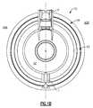
- FIG. 1Bis a rear view of the engine
- FIG. 1Cis a side view of the engine integrated with a pylon
- FIG. 1Dis a perspective view of the engine integrated with a pylon
- FIG. 2Ais a sectional side view of the VAFN in a closed position
- FIG. 2Bis a sectional side view of the VAFN in an open position
- FIG. 3is a graph of a bypass duct normalized cross-sectional area distribution.
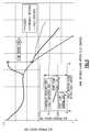
- FIG. 4is a graph of a Effective Area Increase vs. Nozzle Translation
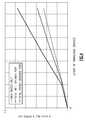
- FIG. 5is a graph of a duct area distribution
- FIG. 6Ais schematic geometric view of the auxiliary port location
- FIG. 6Bis schematic geometric view of the auxiliary port entrance angle
- FIG. 6Cis schematic geometric view of a VAFN outer surface curvature.
- FIG. 1Aillustrates a general partial fragmentary schematic view of a gas turbofan engine 10 suspended from an engine pylon P within an engine nacelle assembly N as is typical of an aircraft designed for subsonic operation.
- the turbofan engine 10includes a core engine within a core nacelle 12 that houses a low spool 14 and high spool 24 .
- the low spool 14includes a low pressure compressor 16 and low pressure turbine 18 .
- the low spool 14drives a fan section 20 through a gear train 22 .
- the high spool 24includes a high pressure compressor 26 and high pressure turbine 28 .
- a combustor 30is arranged between the high pressure compressor 26 and high pressure turbine 28 .
- the low and high spools 14 , 24rotate about an engine axis of rotation A.
- the engine 10is preferably a high-bypass geared architecture aircraft engine.
- the engine 10 bypass ratiois greater than ten (10:1)
- the turbofan diameteris significantly larger than that of the low pressure compressor 16
- the low pressure turbine 18has a pressure ratio that is greater than 5:1.
- the gear train 22may be an epicycle gear train such as a planetary gear system or other gear system with a gear reduction ratio of greater than 2.5:1. It should be understood, however, that the above parameters are only exemplary of one embodiment of a geared architecture engine and that the present invention is applicable to other gas turbine engines including direct drive turbofans.
- the fan section 20communicates airflow into the core nacelle 12 to power the low pressure compressor 16 and the high pressure compressor 26 .
- Core airflow compressed by the low pressure compressor 16 and the high pressure compressor 26is mixed with the fuel in the combustor 30 and expanded over the high pressure turbine 28 and low pressure turbine 18 .
- the turbines 28 , 18are coupled for rotation with, respective, spools 24 , 14 to rotationally drive the compressors 26 , 16 and through the gear train 22 , the fan section 20 in response to the expansion.
- a core engine exhaust Eexits the core nacelle 12 through a core nozzle 43 defined between the core nacelle 12 and a tail cone 32 .
- the core nacelle 12is supported within the fan nacelle 34 by structure 36 often generically referred to as Fan Exit Guide Vanes (FEGVs).
- a bypass flow path 40is defined between the core nacelle 12 and the fan nacelle 34 .
- the engine 10generates a high bypass flow arrangement with a bypass ratio in which approximately 80 percent of the airflow entering the fan nacelle 34 becomes bypass flow B.
- the bypass flow Bcommunicates through the generally annular fan bypass flow path 40 and is discharged from the engine 10 through a fan variable area nozzle (VAFN) 42 which defines a fan nozzle exit area 44 between the fan nacelle 34 and the core nacelle 12 at a fan nacelle end segment 34 S of the fan nacelle 34 downstream of the fan section 20 .
- VAFNfan variable area nozzle
- Thrustis a function of density, velocity, and area. One or more of these parameters can be manipulated to vary the amount and direction of thrust provided by the bypass flow B.
- the VAFN 42operates to effectively vary the area of the fan nozzle exit area 44 to selectively adjust the pressure ratio of the bypass flow B in response to a controller C.
- Low pressure ratio turbofansare desirable for their high propulsive efficiency. However, low pressure ratio fans may be inherently susceptible to fan stability/flutter problems at low power and low flight speeds.
- the VAFNallows the engine to change to a more favorable fan operating line at low power, avoiding the instability region, and still provide the relatively smaller nozzle area necessary to obtain a high-efficiency fan operating line at cruise.
- the fan section 20 of the engine 10is preferably designed for a particular flight condition—typically cruise at 0.8M and 35,000 feet. As the fan blades within the fan section 20 are efficiently designed at a particular fixed stagger angle for an efficient cruise condition, the VAFN 42 is operated to effectively vary the fan nozzle exit area 44 to adjust fan bypass air flow such that the angle of attack or incidence on the fan blades is maintained close to the design incidence for efficient engine operation at other flight conditions, such as landing and takeoff to thus provide optimized engine operation over a range of flight conditions with respect to performance and other operational parameters such as noise levels.
- the VAFN 42is separated into at least two sectors 42 A- 42 B ( FIG. 1B ) defined between the pylon P and a lower Bi-Fi splitter L which typically interconnects a larger diameter fan duct reverser cowl and a smaller diameter core cowl ( FIGS. 1C and 1D ).
- Each of the at least two sectors 42 A- 42 Bare independently adjustable to asymmetrically vary the fan nozzle exit area 44 to generate vectored thrust. It should be understood that although two segments are illustrated, any number of segments may alternatively or additionally be provided.
- the VAFN 42communicates with a controller C or the like to adjust the fan nozzle exit area 44 in a symmetrical and asymmetrical manner.
- Other control systemsincluding an engine controller or aircraft flight control system may also be usable with the present invention.
- By separately adjusting the circumferential sectors 42 A- 42 B of the VAFN 42 to provide an asymmetrical fan nozzle exit area 44engine bypass flow is selectively vectored to provide, for example only, trim balance or thrust controlled maneuvering enhanced ground operations or short field performance.
- the VAFN 42generally includes an auxiliary port assembly 50 having a first fan nacelle section 52 and a second fan nacelle section 54 movably mounted relative the first fan nacelle section 52 .
- the second fan nacelle section 54axially slides along the engine axis A relative the fixed first fan nacelle section 52 to change the effective area of the fan nozzle exit area 44 .
- the second fan nacelle section 54slides aftward upon a track fairing 56 A, 56 B (illustrated schematically in FIGS. 1C and 1D ) in response to an actuator 58 (illustrated schematically).
- the track fairing 56 A, 56 Bextend from the first fan nacelle section 52 adjacent the respective pylon P and the lower Bi-Fi splitter L ( FIG. 1D ).
- the VAFN 42changes the physical area and geometry of the bypass flow path 40 during particular flight conditions.
- the bypass flow Bis effectively altered by sliding of the second fan nacelle section 54 relative the first fan nacelle section 52 between a closed position ( FIG. 2A ) and an open position ( FIG. 2B ).
- the auxiliary port assembly 50is closed by positioning the second fan nacelle section 54 in-line with the first fan nacelle section 52 to define the fan nozzle exit area 44 as exit area F 0 ( FIG. 2A ).
- the VAFN 42is opened by moving the second fan nacelle section 54 aftward along the track fairing 56 A, 56 B away from the first fan nacelle section 52 to open an auxiliary port 60 which extends between the open second fan nacelle section 54 relative the first fan nacelle section 52 to essentially provide an increased fan nozzle exit area 44 exit area F 1 . That is, the exit area F 1 with the port 60 is greater than exit area F 0 ( FIG. 2B ).
- the auxiliary port 60is incorporated into the exhaust system of a high bypass ratio commercial turbofan engine within the bypass duct aft of the Fan Exit Guide Vanes (FEGVs; FIGS. 2A , 2 B).
- the auxiliary port 60is located in the aft section of the bypass duct outer wall.
- the bypass duct area distribution, the effective area increase vs. translation ( FIG. 4 ), area distribution ( FIG. 5 ), and auxiliary port 60 location ( FIG. 6A ) and wall curvatures ( FIG. 6B-6C )are tailored to provide a proper flow-field that allows the auxiliary port 60 to obtain the required additional effective exit area.
- the auxiliary port 60will essentially double the effective area gain due to translation.
- the auxiliary port 60provides a relatively low weight method of providing increased exit area to control the fan operating line without causing high system losses or unacceptable aircraft installation issues.
- the auxiliary port exit plane 44 B(defined as the plane between the stationary section's trailing edge and the moving sections leading edge) initially has an opening in which the exit plane normal vector is near-axial, but as the stroke increases, the normal vector becomes more inclined and approaches a near-radial vector. Once the exit plane normal has become near-radial, the maximum auxiliary port effectiveness has been reached. Once this point is reached, the rate of the effective area vs. translation changes from steep slope of the “well designed port”the shallow rate of the “main nozzle only”, since additional area will be provided through the main nozzle 44 A due to the inward slope of the core nacelle 12 . A well designed auxiliary port nozzle will achieve approximately +25% effective area before the port effectiveness limit is reached.
- the auxiliary portdoubles the rate of additional effectiveness. Outside of this range, the rate of additional effectiveness may be equivalent to a translating nozzle that has no auxiliary port. Or put another way, the auxiliary port reduces the stroke necessary for a pure translating nozzle to achieve a desired effective area.
- the cross-sectional area at the auxiliary port 60is greater than the maximum required effective area of the VAFN 42 and the bypass duct area distribution is tailored to ensure the duct cross-sectional area forward of the auxiliary port 60 is greater than the port opening cross-sectional area. This avoids a situation where an upstream internal cross-section becomes the controlling flow area (i.e. is smaller than the exit area), which can lead to operational limits and structural issues.
- the auxiliary port 60 in the disclosed embodimentis located no more forward than 0.1 DEL_X/L_DUCT defined from a point D at the largest radius Rmax of the annular fan bypass flow path 40 defined by the second fan nacelle section 54 .
- Rmaxis defined through point D and perpendicular to the engine axis A.
- Point D in the disclosed non limiting embodimentis located on an inner wall surface 54 I of the second fan nacelle section 54 when the second fan nacelle section 54 is in a closed position.
- DEL_Xis the axial distance to the forward most point of the auxiliary port 60 from Rmax.
- L_DUCTis the overall axial length of the annular fan bypass flow path 40 .
- the angle between the mean port line and the fan duct outer wallis relatively low to provide well-behaved, low loss exit flow.
- the auxiliary port 60 entrance angle (Theta_in) relative to the fan bypass duct OD wallis less than 20 degrees ( FIG. 6B ) while the outer VAFN surface has an R_ARC/CHORD>0.7 where R_ARC is a radial distance from the engine axis A to a radial outer wall surface 54 O of the second fan nacelle section 54 and CHORD is the chord length of the second fan nacelle section 54 . ( FIG. 6C ).
- the curvature of the outer wall surface 54 O near the auxiliary port 60promotes flow through the auxiliary port 60 .
- the stroke of the second fan nacelle section 54 necessary to obtain an additional 20% effective exit areais approximately 8.4 inches.
- the VAFN 42communicates with the controller C to move the second fan nacelle section 54 relative the first fan nacelle section 52 of the auxiliary port assembly 50 to effectively vary the area defined by the fan nozzle exit area 44 .
- Various control systemsincluding an engine controller or an aircraft flight control system may also be usable with the present invention.
- engine thrust and fuel economyare maximized during each flight regime by varying the fan nozzle exit area.
- engine bypass flowis selectively vectored to provide, for example only, trim balance, thrust controlled maneuvering, enhanced ground operations and short field performance.
Landscapes
- Engineering & Computer Science (AREA)
- Chemical & Material Sciences (AREA)
- Combustion & Propulsion (AREA)
- Mechanical Engineering (AREA)
- General Engineering & Computer Science (AREA)
- Aviation & Aerospace Engineering (AREA)
- Structures Of Non-Positive Displacement Pumps (AREA)
- Control Of Turbines (AREA)
Abstract
Description
Claims (15)
Priority Applications (16)
| Application Number | Priority Date | Filing Date | Title |
|---|---|---|---|
| US11/843,675US8074440B2 (en) | 2007-08-23 | 2007-08-23 | Gas turbine engine with axial movable fan variable area nozzle |
| EP08252757AEP2028359A3 (en) | 2007-08-23 | 2008-08-20 | Gas turbine engine with axial movable fan variable area nozzle |
| US13/314,365US9701415B2 (en) | 2007-08-23 | 2011-12-08 | Gas turbine engine with axial movable fan variable area nozzle |
| US13/340,787US10167813B2 (en) | 2007-08-23 | 2011-12-30 | Gas turbine engine with fan variable area nozzle to reduce fan instability |
| US13/340,810US9494084B2 (en) | 2007-08-23 | 2011-12-30 | Gas turbine engine with fan variable area nozzle for low fan pressure ratio |
| US13/486,596US10047628B2 (en) | 2007-08-23 | 2012-06-01 | Gas turbine engine with fan variable area nozzle for low fan pressure ratio |
| US15/345,959US20170051630A1 (en) | 2007-08-23 | 2016-11-08 | Gas turbine engine with fan variable area nozzle for low fan pressure ratio |
| US15/360,053US9822732B2 (en) | 2007-08-23 | 2016-11-23 | Gas turbine engine with axial movable fan variable area nozzle |
| US15/360,092US9771893B2 (en) | 2007-08-23 | 2016-11-23 | Gas turbine engine with axial movable fan variable area nozzle |
| US15/359,948US20170074208A1 (en) | 2007-08-23 | 2016-11-23 | Gas turbine engine with axial movable fan variable area nozzle |
| US15/360,001US9784212B2 (en) | 2007-08-23 | 2016-11-23 | Gas turbine engine with axial movable fan variable area nozzle |
| US15/712,238US10174715B2 (en) | 2007-08-23 | 2017-09-22 | Gas turbine engine with axial movable fan variable area nozzle |
| US15/712,251US10174716B2 (en) | 2007-08-23 | 2017-09-22 | Gas turbine engine with axial movable fan variable area nozzle |
| US15/729,748US10087885B2 (en) | 2007-08-23 | 2017-10-11 | Gas turbine engine with axial movable fan variable area nozzle |
| US16/214,755US11162456B2 (en) | 2007-08-23 | 2018-12-10 | Gas turbine engine with axial movable fan variable area nozzle |
| US17/326,904US11454193B2 (en) | 2007-08-23 | 2021-05-21 | Gas turbine engine with axial movable fan variable area nozzle |
Applications Claiming Priority (1)
| Application Number | Priority Date | Filing Date | Title |
|---|---|---|---|
| US11/843,675US8074440B2 (en) | 2007-08-23 | 2007-08-23 | Gas turbine engine with axial movable fan variable area nozzle |
Related Child Applications (2)
| Application Number | Title | Priority Date | Filing Date |
|---|---|---|---|
| US13/314,365ContinuationUS9701415B2 (en) | 2007-08-23 | 2011-12-08 | Gas turbine engine with axial movable fan variable area nozzle |
| US13/314,365Continuation-In-PartUS9701415B2 (en) | 2007-08-23 | 2011-12-08 | Gas turbine engine with axial movable fan variable area nozzle |
Publications (2)
| Publication Number | Publication Date |
|---|---|
| US20090053058A1 US20090053058A1 (en) | 2009-02-26 |
| US8074440B2true US8074440B2 (en) | 2011-12-13 |
Family
ID=40032854
Family Applications (1)
| Application Number | Title | Priority Date | Filing Date |
|---|---|---|---|
| US11/843,675Active2030-10-09US8074440B2 (en) | 2007-08-23 | 2007-08-23 | Gas turbine engine with axial movable fan variable area nozzle |
Country Status (2)
| Country | Link |
|---|---|
| US (1) | US8074440B2 (en) |
| EP (1) | EP2028359A3 (en) |
Cited By (32)
| Publication number | Priority date | Publication date | Assignee | Title |
|---|---|---|---|---|
| US20080044276A1 (en)* | 2006-08-15 | 2008-02-21 | Mccune Michael E | Ring gear mounting arrangement with oil scavenge scheme |
| WO2013141931A1 (en)* | 2012-01-09 | 2013-09-26 | United Technologies Corporation | Gas turbine engine with geared architecture |
| WO2013147976A1 (en)* | 2012-01-31 | 2013-10-03 | United Technologies Corporation | Gas turbine engine seal carrier |
| WO2013147975A1 (en)* | 2012-01-31 | 2013-10-03 | United Technologies Corporation | Buffer system for a gas turbine engine |
| US8708863B2 (en) | 2006-08-15 | 2014-04-29 | United Technologies Corporation | Epicyclic gear train |
| WO2013154650A3 (en)* | 2012-01-31 | 2014-05-22 | United Technologies Corporation | Anti-icing stator assembly for a gas turbine |
| CN104011359A (en)* | 2011-12-30 | 2014-08-27 | 联合工艺公司 | Gas turbine engine with fan variable area nozzle for low fan pressure ratio |
| US8858388B2 (en) | 2006-08-15 | 2014-10-14 | United Technologies Corporation | Gas turbine engine gear train |
| US8894538B2 (en) | 2006-08-15 | 2014-11-25 | United Technologies Corporation | Gas turbine engine with geared architecture |
| US8939864B2 (en) | 2006-08-15 | 2015-01-27 | United Technologies Corporation | Gas turbine engine lubrication |
| US20160003194A1 (en)* | 2013-03-15 | 2016-01-07 | United Technologies Corporation | Asymmetric Fan Nozzle in High-BPR Separate-Flow Nacelle |
| US20160047274A1 (en)* | 2014-08-18 | 2016-02-18 | Rohr, Inc. | Actively controlled cooling air exhaust door on an aircraft engine nacelle |
| US9347397B2 (en) | 2012-08-02 | 2016-05-24 | United Technologies Corporation | Reflex annular vent nozzle |
| US9488130B2 (en) | 2013-10-17 | 2016-11-08 | Honeywell International Inc. | Variable area fan nozzle systems with improved drive couplings |
| US20170130673A1 (en)* | 2012-01-24 | 2017-05-11 | United Technologies Corporation | Geared turbomachine fan and compressor rotation |
| US9869190B2 (en) | 2014-05-30 | 2018-01-16 | General Electric Company | Variable-pitch rotor with remote counterweights |
| US9976437B2 (en) | 2006-08-15 | 2018-05-22 | United Technologies Corporation | Epicyclic gear train |
| CN108131325A (en)* | 2017-12-19 | 2018-06-08 | 北京理工大学 | The axial through-flow rotating vane shock wave stator blade fan grade of Supersonic |
| US10072510B2 (en) | 2014-11-21 | 2018-09-11 | General Electric Company | Variable pitch fan for gas turbine engine and method of assembling the same |
| US10082105B2 (en) | 2006-08-15 | 2018-09-25 | United Technologies Corporation | Gas turbine engine with geared architecture |
| US10100653B2 (en) | 2015-10-08 | 2018-10-16 | General Electric Company | Variable pitch fan blade retention system |
| US10400621B2 (en) | 2013-03-04 | 2019-09-03 | United Technologies Corporation | Pivot door thrust reverser with variable area nozzle |
| US10450898B2 (en) | 2015-02-13 | 2019-10-22 | United Technologies Corporation | Track fairing assembly for a turbine engine nacelle |
| US10451004B2 (en) | 2008-06-02 | 2019-10-22 | United Technologies Corporation | Gas turbine engine with low stage count low pressure turbine |
| US10654577B2 (en) | 2017-02-22 | 2020-05-19 | General Electric Company | Rainbow flowpath low pressure turbine rotor assembly |
| US11053797B2 (en) | 2017-01-23 | 2021-07-06 | General Electric Company | Rotor thrust balanced turbine engine |
| US11162456B2 (en) | 2007-08-23 | 2021-11-02 | Raytheon Technologies Corporation | Gas turbine engine with axial movable fan variable area nozzle |
| US11421627B2 (en) | 2017-02-22 | 2022-08-23 | General Electric Company | Aircraft and direct drive engine under wing installation |
| US11428160B2 (en) | 2020-12-31 | 2022-08-30 | General Electric Company | Gas turbine engine with interdigitated turbine and gear assembly |
| US11674435B2 (en) | 2021-06-29 | 2023-06-13 | General Electric Company | Levered counterweight feathering system |
| US11795964B2 (en) | 2021-07-16 | 2023-10-24 | General Electric Company | Levered counterweight feathering system |
| US12018838B2 (en) | 2022-06-21 | 2024-06-25 | General Electric Company | Cowl assembly for a gas turbine engine |
Families Citing this family (53)
| Publication number | Priority date | Publication date | Assignee | Title |
|---|---|---|---|---|
| US9759087B2 (en)* | 2007-08-08 | 2017-09-12 | Rohr, Inc. | Translating variable area fan nozzle providing an upstream bypass flow exit |
| EP2181262B1 (en)* | 2007-08-08 | 2012-05-16 | Rohr, Inc. | Variable area fan nozzle with bypass flow |
| US10167813B2 (en) | 2007-08-23 | 2019-01-01 | United Technologies Corporation | Gas turbine engine with fan variable area nozzle to reduce fan instability |
| US9494084B2 (en)* | 2007-08-23 | 2016-11-15 | United Technologies Corporation | Gas turbine engine with fan variable area nozzle for low fan pressure ratio |
| US8800914B2 (en) | 2008-06-02 | 2014-08-12 | United Technologies Corporation | Gas turbine engine with low stage count low pressure turbine |
| US8511605B2 (en) | 2008-06-02 | 2013-08-20 | United Technologies Corporation | Gas turbine engine with low stage count low pressure turbine |
| US8807477B2 (en) | 2008-06-02 | 2014-08-19 | United Technologies Corporation | Gas turbine engine compressor arrangement |
| US8128021B2 (en) | 2008-06-02 | 2012-03-06 | United Technologies Corporation | Engine mount system for a turbofan gas turbine engine |
| US8695920B2 (en)* | 2008-06-02 | 2014-04-15 | United Technologies Corporation | Gas turbine engine with low stage count low pressure turbine |
| US9885313B2 (en) | 2009-03-17 | 2018-02-06 | United Technologes Corporation | Gas turbine engine bifurcation located fan variable area nozzle |
| US9057286B2 (en) | 2010-03-30 | 2015-06-16 | United Technologies Corporation | Non-circular aft nacelle cowling geometry |
| US8667802B2 (en)* | 2010-05-06 | 2014-03-11 | Spirit Aerosystems, Inc. | Variable fan duct nozzle translatable core/inner cowl including two overlapping portions made of different materials |
| US8875486B2 (en) | 2010-05-17 | 2014-11-04 | Rohr, Inc. | Guide system for nacelle assembly |
| US8511973B2 (en) | 2010-06-23 | 2013-08-20 | Rohr, Inc. | Guide system for nacelle assembly |
| US8800261B2 (en)* | 2010-07-19 | 2014-08-12 | United Technologies Corporation | Gas turbine engine with noise attenuating variable area fan nozzle |
| US8820088B2 (en)* | 2010-07-27 | 2014-09-02 | United Technologies Corporation | Variable area fan nozzle with acoustic system for a gas turbine engine |
| US20120079804A1 (en)* | 2010-09-30 | 2012-04-05 | Alan Roy Stuart | Cowl assembly |
| US8997497B2 (en) | 2010-10-29 | 2015-04-07 | United Technologies Corporation | Gas turbine engine with variable area fan nozzle |
| US8910482B2 (en)* | 2011-02-02 | 2014-12-16 | The Boeing Company | Aircraft engine nozzle |
| US9631558B2 (en) | 2012-01-03 | 2017-04-25 | United Technologies Corporation | Geared architecture for high speed and small volume fan drive turbine |
| US9239012B2 (en) | 2011-06-08 | 2016-01-19 | United Technologies Corporation | Flexible support structure for a geared architecture gas turbine engine |
| US9523422B2 (en) | 2011-06-08 | 2016-12-20 | United Technologies Corporation | Flexible support structure for a geared architecture gas turbine engine |
| WO2012174247A1 (en)* | 2011-06-14 | 2012-12-20 | Rolls-Royce North American Technologies, Inc. | Aircraft powerplant |
| US8613398B2 (en) | 2011-06-17 | 2013-12-24 | General Electric Company | Apparatus and methods for linear actuation of flow altering components of jet engine nozzle |
| CN104040158A (en)* | 2011-12-08 | 2014-09-10 | 联合工艺公司 | Gas turbine engine with axial movable fan variable area nozzle |
| EP3088702A1 (en)* | 2011-12-30 | 2016-11-02 | United Technologies Corporation | Gas turbine engine gear train |
| WO2013141934A2 (en)* | 2011-12-30 | 2013-09-26 | United Technologies Corporation | Gas turbine engine with fan variable area nozzle |
| BR102012028942B1 (en)* | 2011-12-30 | 2021-06-15 | United Technologies Corporation | GAS TURBINE ENGINE |
| BR102012028940A2 (en)* | 2011-12-30 | 2015-10-06 | United Technologies Corp | gas turbine engine |
| EP2798187A4 (en)* | 2011-12-30 | 2015-08-19 | United Technologies Corp | GAS TURBINE ENGINE EQUIPPED WITH VARIABLE SECTION NOZZLE FOR FAN TO REDUCE FAN INSTABILITY |
| CA2853694C (en)* | 2012-01-09 | 2016-03-22 | United Technologies Corporation | Gas turbine engine with geared architecture |
| US8375699B1 (en) | 2012-01-31 | 2013-02-19 | United Technologies Corporation | Variable area fan nozzle with wall thickness distribution |
| US20130192195A1 (en)* | 2012-01-31 | 2013-08-01 | Eric J. Wehmeier | Gas turbine engine with compressor inlet guide vane positioned for starting |
| US9394852B2 (en) | 2012-01-31 | 2016-07-19 | United Technologies Corporation | Variable area fan nozzle with wall thickness distribution |
| US10287914B2 (en) | 2012-01-31 | 2019-05-14 | United Technologies Corporation | Gas turbine engine with high speed low pressure turbine section and bearing support features |
| US20130255275A1 (en)* | 2012-04-02 | 2013-10-03 | Frederick M. Schwarz | Geared turbofan engine with power density range |
| US10138809B2 (en) | 2012-04-02 | 2018-11-27 | United Technologies Corporation | Geared turbofan engine with a high ratio of thrust to turbine volume |
| US10125693B2 (en) | 2012-04-02 | 2018-11-13 | United Technologies Corporation | Geared turbofan engine with power density range |
| WO2013165771A1 (en)* | 2012-04-30 | 2013-11-07 | United Technologies Corporation | Geared turbofan with distributed accessory gearboxes |
| US9303590B2 (en) | 2012-05-22 | 2016-04-05 | Spirit Aerosystems, Inc. | Variable area fan nozzle actuation system |
| US8572943B1 (en) | 2012-05-31 | 2013-11-05 | United Technologies Corporation | Fundamental gear system architecture |
| US20150308351A1 (en) | 2012-05-31 | 2015-10-29 | United Technologies Corporation | Fundamental gear system architecture |
| US8756908B2 (en) | 2012-05-31 | 2014-06-24 | United Technologies Corporation | Fundamental gear system architecture |
| US20140083079A1 (en)* | 2012-09-26 | 2014-03-27 | United Technologies Corporation | Geared turbofan primary and secondary nozzle integration geometry |
| US10119400B2 (en)* | 2012-09-28 | 2018-11-06 | United Technologies Corporation | High pressure rotor disk |
| US10036316B2 (en) | 2012-10-02 | 2018-07-31 | United Technologies Corporation | Geared turbofan engine with high compressor exit temperature |
| WO2014055114A1 (en) | 2012-10-02 | 2014-04-10 | United Technologies Corporation | Geared turbofan engine with high compressor exit temperature |
| WO2014143267A1 (en)* | 2013-03-15 | 2014-09-18 | United Technologies Corporation | Gas turbine engine with low fan noise |
| EP2989313A4 (en)* | 2013-04-24 | 2016-04-20 | United Technologies Corp | Geared turbine engine with o-duct and thrust reverser |
| EP3058202A4 (en) | 2013-10-16 | 2017-06-28 | United Technologies Corporation | Geared turbofan engine with targeted modular efficiency |
| US10344711B2 (en)* | 2016-01-11 | 2019-07-09 | Rolls-Royce Corporation | System and method of alleviating blade flutter |
| US10465539B2 (en)* | 2017-08-04 | 2019-11-05 | Pratt & Whitney Canada Corp. | Rotor casing |
| CN114542323B (en)* | 2021-12-29 | 2023-11-28 | 中国航空工业集团公司沈阳飞机设计研究所 | Control method and device for vector spray pipe |
Citations (18)
| Publication number | Priority date | Publication date | Assignee | Title |
|---|---|---|---|---|
| FR1503425A (en) | 1965-12-22 | 1967-11-24 | Chepos Zd Y Chemickeho A Potra | Suspended demoulding device or hydraulic ingot pincer |
| US3779010A (en) | 1972-08-17 | 1973-12-18 | Gen Electric | Combined thrust reversing and throat varying mechanism for a gas turbine engine |
| US3820719A (en) | 1972-05-09 | 1974-06-28 | Rolls Royce 1971 Ltd | Gas turbine engines |
| US4327548A (en) | 1979-03-10 | 1982-05-04 | Rolls-Royce Limited | Gas turbine engine power plant |
| GB2189550A (en) | 1986-04-25 | 1987-10-28 | Rolls Royce | A gas turbine engine powerplant with flow control devices |
| US4922713A (en)* | 1987-11-05 | 1990-05-08 | Societe Anonyme Dite Hispano-Suiza | Turbojet engine thrust reverser with variable exhaust cross-section |
| US5524847A (en) | 1993-09-07 | 1996-06-11 | United Technologies Corporation | Nacelle and mounting arrangement for an aircraft engine |
| US5577381A (en) | 1994-12-06 | 1996-11-26 | United Technologies Corporation | Exhaust nozzle cooling scheme for gas turbine engine |
| US5586431A (en) | 1994-12-06 | 1996-12-24 | United Technologies Corporation | Aircraft nacelle ventilation and engine exhaust nozzle cooling |
| US5593112A (en) | 1994-12-06 | 1997-01-14 | United Technologies Corporation | Nacelle air pump for vector nozzles for aircraft |
| US5655360A (en) | 1995-05-31 | 1997-08-12 | General Electric Company | Thrust reverser with variable nozzle |
| US5778659A (en) | 1994-10-20 | 1998-07-14 | United Technologies Corporation | Variable area fan exhaust nozzle having mechanically separate sleeve and thrust reverser actuation systems |
| US5806302A (en) | 1996-09-24 | 1998-09-15 | Rohr, Inc. | Variable fan exhaust area nozzle for aircraft gas turbine engine with thrust reverser |
| US5833140A (en)* | 1996-12-12 | 1998-11-10 | United Technologies Corporation | Variable geometry exhaust nozzle for a turbine engine |
| US5853148A (en) | 1995-12-19 | 1998-12-29 | Societe De Construction Des Avions Hurel-Dubois | Thrust reverser with adjustable section nozzle for aircraft jet engine |
| US20020069637A1 (en)* | 2000-12-07 | 2002-06-13 | Becquerelle Samuel Raymond Germain | Speed-reducing gear unit to absorb the axial loads generated by a turbojet fan |
| US20060101807A1 (en) | 2004-11-12 | 2006-05-18 | Wood Jeffrey H | Morphing structure |
| US20100064659A1 (en)* | 2007-08-08 | 2010-03-18 | Rohr, Inc. | Translating variable area fan nozzle with split beavertail fairings |
- 2007
- 2007-08-23USUS11/843,675patent/US8074440B2/enactiveActive
- 2008
- 2008-08-20EPEP08252757Apatent/EP2028359A3/ennot_activeWithdrawn
Patent Citations (18)
| Publication number | Priority date | Publication date | Assignee | Title |
|---|---|---|---|---|
| FR1503425A (en) | 1965-12-22 | 1967-11-24 | Chepos Zd Y Chemickeho A Potra | Suspended demoulding device or hydraulic ingot pincer |
| US3820719A (en) | 1972-05-09 | 1974-06-28 | Rolls Royce 1971 Ltd | Gas turbine engines |
| US3779010A (en) | 1972-08-17 | 1973-12-18 | Gen Electric | Combined thrust reversing and throat varying mechanism for a gas turbine engine |
| US4327548A (en) | 1979-03-10 | 1982-05-04 | Rolls-Royce Limited | Gas turbine engine power plant |
| GB2189550A (en) | 1986-04-25 | 1987-10-28 | Rolls Royce | A gas turbine engine powerplant with flow control devices |
| US4922713A (en)* | 1987-11-05 | 1990-05-08 | Societe Anonyme Dite Hispano-Suiza | Turbojet engine thrust reverser with variable exhaust cross-section |
| US5524847A (en) | 1993-09-07 | 1996-06-11 | United Technologies Corporation | Nacelle and mounting arrangement for an aircraft engine |
| US5778659A (en) | 1994-10-20 | 1998-07-14 | United Technologies Corporation | Variable area fan exhaust nozzle having mechanically separate sleeve and thrust reverser actuation systems |
| US5586431A (en) | 1994-12-06 | 1996-12-24 | United Technologies Corporation | Aircraft nacelle ventilation and engine exhaust nozzle cooling |
| US5593112A (en) | 1994-12-06 | 1997-01-14 | United Technologies Corporation | Nacelle air pump for vector nozzles for aircraft |
| US5577381A (en) | 1994-12-06 | 1996-11-26 | United Technologies Corporation | Exhaust nozzle cooling scheme for gas turbine engine |
| US5655360A (en) | 1995-05-31 | 1997-08-12 | General Electric Company | Thrust reverser with variable nozzle |
| US5853148A (en) | 1995-12-19 | 1998-12-29 | Societe De Construction Des Avions Hurel-Dubois | Thrust reverser with adjustable section nozzle for aircraft jet engine |
| US5806302A (en) | 1996-09-24 | 1998-09-15 | Rohr, Inc. | Variable fan exhaust area nozzle for aircraft gas turbine engine with thrust reverser |
| US5833140A (en)* | 1996-12-12 | 1998-11-10 | United Technologies Corporation | Variable geometry exhaust nozzle for a turbine engine |
| US20020069637A1 (en)* | 2000-12-07 | 2002-06-13 | Becquerelle Samuel Raymond Germain | Speed-reducing gear unit to absorb the axial loads generated by a turbojet fan |
| US20060101807A1 (en) | 2004-11-12 | 2006-05-18 | Wood Jeffrey H | Morphing structure |
| US20100064659A1 (en)* | 2007-08-08 | 2010-03-18 | Rohr, Inc. | Translating variable area fan nozzle with split beavertail fairings |
Non-Patent Citations (1)
| Title |
|---|
| Eastman Jacobs, The Characteristics of 78 Related Airfoil Sections From Tests in the Variable-Density Wind Tunnel, Nov. 1933, pp. 2-61.* |
Cited By (71)
| Publication number | Priority date | Publication date | Assignee | Title |
|---|---|---|---|---|
| US9115650B2 (en) | 2006-08-15 | 2015-08-25 | United Technologies Corporation | Ring gear mounting arrangement with oil scavenge scheme |
| US11680492B2 (en) | 2006-08-15 | 2023-06-20 | Raytheon Technologies Corporation | Epicyclic gear train |
| US12385409B2 (en) | 2006-08-15 | 2025-08-12 | Rtx Corporation | Epicyclic gear train |
| US10570855B2 (en) | 2006-08-15 | 2020-02-25 | United Technologies Corporation | Gas turbine engine with geared architecture |
| US8708863B2 (en) | 2006-08-15 | 2014-04-29 | United Technologies Corporation | Epicyclic gear train |
| US12084978B2 (en) | 2006-08-15 | 2024-09-10 | Rtx Corporation | Epicyclic gear train |
| US8740740B2 (en) | 2006-08-15 | 2014-06-03 | United Technologies Corporation | Ring gear mounting arrangement with oil scavenge scheme |
| US8753243B2 (en) | 2006-08-15 | 2014-06-17 | United Technologies Corporation | Ring gear mounting arrangement with oil scavenge scheme |
| US8764604B2 (en) | 2006-08-15 | 2014-07-01 | United Technologies Corporation | Ring gear mounting arrangement with oil scavenge scheme |
| US8795122B2 (en) | 2006-08-15 | 2014-08-05 | United Technologies Corporation | Tapered bearings |
| US10527151B1 (en) | 2006-08-15 | 2020-01-07 | United Technologies Corporation | Gas turbine engine with geared architecture |
| US8858388B2 (en) | 2006-08-15 | 2014-10-14 | United Technologies Corporation | Gas turbine engine gear train |
| US8894538B2 (en) | 2006-08-15 | 2014-11-25 | United Technologies Corporation | Gas turbine engine with geared architecture |
| US8939864B2 (en) | 2006-08-15 | 2015-01-27 | United Technologies Corporation | Gas turbine engine lubrication |
| US10577965B2 (en) | 2006-08-15 | 2020-03-03 | United Technologies Corporation | Epicyclic gear train |
| US10107231B2 (en) | 2006-08-15 | 2018-10-23 | United Technologies Corporation | Gas turbine engine with geared architecture |
| US20080044276A1 (en)* | 2006-08-15 | 2008-02-21 | Mccune Michael E | Ring gear mounting arrangement with oil scavenge scheme |
| US10830334B2 (en) | 2006-08-15 | 2020-11-10 | Raytheon Technologies Corporation | Ring gear mounting arrangement with oil scavenge scheme |
| US10591047B2 (en) | 2006-08-15 | 2020-03-17 | United Technologies Corporation | Ring gear mounting arrangement with oil scavenge scheme |
| US11499624B2 (en) | 2006-08-15 | 2022-11-15 | Raytheon Technologies Corporation | Ring gear mounting arrangement with oil scavenge scheme |
| US10890245B2 (en) | 2006-08-15 | 2021-01-12 | Raytheon Technologies Corporation | Epicyclic gear train |
| US10907579B2 (en) | 2006-08-15 | 2021-02-02 | Raytheon Technologies Corporation | Gas turbine engine with geared architecture |
| US9657572B2 (en) | 2006-08-15 | 2017-05-23 | United Technologies Corporation | Ring gear mounting arrangement with oil scavenge scheme |
| US11378039B2 (en) | 2006-08-15 | 2022-07-05 | Raytheon Technologies Corporation | Ring gear mounting arrangement with oil scavenge scheme |
| US11319831B2 (en) | 2006-08-15 | 2022-05-03 | Raytheon Technologies Corporation | Epicyclic gear train |
| US9951860B2 (en) | 2006-08-15 | 2018-04-24 | United Technologies Corporation | Ring gear mounting arrangement with oil scavenge scheme |
| US9976437B2 (en) | 2006-08-15 | 2018-05-22 | United Technologies Corporation | Epicyclic gear train |
| US10196989B2 (en) | 2006-08-15 | 2019-02-05 | United Technologies Corporation | Gas turbine engine gear train |
| US11221066B2 (en) | 2006-08-15 | 2022-01-11 | Raytheon Technologies Corporation | Ring gear mounting arrangement with oil scavenge scheme |
| US10082105B2 (en) | 2006-08-15 | 2018-09-25 | United Technologies Corporation | Gas turbine engine with geared architecture |
| US10125858B2 (en) | 2006-08-15 | 2018-11-13 | United Technologies Corporation | Ring gear mounting arrangement with oil scavenge scheme |
| US11162456B2 (en) | 2007-08-23 | 2021-11-02 | Raytheon Technologies Corporation | Gas turbine engine with axial movable fan variable area nozzle |
| US11454193B2 (en) | 2007-08-23 | 2022-09-27 | Raytheon Technologies Corporation | Gas turbine engine with axial movable fan variable area nozzle |
| US11286883B2 (en) | 2008-06-02 | 2022-03-29 | Raytheon Technologies Corporation | Gas turbine engine with low stage count low pressure turbine and engine mounting arrangement |
| US10451004B2 (en) | 2008-06-02 | 2019-10-22 | United Technologies Corporation | Gas turbine engine with low stage count low pressure turbine |
| US11731773B2 (en) | 2008-06-02 | 2023-08-22 | Raytheon Technologies Corporation | Engine mount system for a gas turbine engine |
| US12179929B2 (en) | 2008-06-02 | 2024-12-31 | Rtx Corporation | Engine mount system for a gas turbine engine |
| CN104011359A (en)* | 2011-12-30 | 2014-08-27 | 联合工艺公司 | Gas turbine engine with fan variable area nozzle for low fan pressure ratio |
| WO2013141931A1 (en)* | 2012-01-09 | 2013-09-26 | United Technologies Corporation | Gas turbine engine with geared architecture |
| US10584660B2 (en)* | 2012-01-24 | 2020-03-10 | United Technologies Corporation | Geared turbomachine fan and compressor rotation |
| US20170130673A1 (en)* | 2012-01-24 | 2017-05-11 | United Technologies Corporation | Geared turbomachine fan and compressor rotation |
| US11566587B2 (en) | 2012-01-24 | 2023-01-31 | Raytheon Technologies Corporation | Geared turbomachine fan and compressor rotation |
| US9291064B2 (en) | 2012-01-31 | 2016-03-22 | United Technologies Corporation | Anti-icing core inlet stator assembly for a gas turbine engine |
| US9879602B2 (en) | 2012-01-31 | 2018-01-30 | United Technologies Corporation | Compressed air bleed supply for buffer system |
| WO2013147975A1 (en)* | 2012-01-31 | 2013-10-03 | United Technologies Corporation | Buffer system for a gas turbine engine |
| US10731563B2 (en) | 2012-01-31 | 2020-08-04 | Raytheon Technologies Corporation | Compressed air bleed supply for buffer system |
| US9255487B2 (en) | 2012-01-31 | 2016-02-09 | United Technologies Corporation | Gas turbine engine seal carrier |
| WO2013154650A3 (en)* | 2012-01-31 | 2014-05-22 | United Technologies Corporation | Anti-icing stator assembly for a gas turbine |
| WO2013147976A1 (en)* | 2012-01-31 | 2013-10-03 | United Technologies Corporation | Gas turbine engine seal carrier |
| US11391205B2 (en) | 2012-01-31 | 2022-07-19 | Raytheon Technologies Corporation | Anti-icing core inlet stator assembly for a gas turbine engine |
| US9347397B2 (en) | 2012-08-02 | 2016-05-24 | United Technologies Corporation | Reflex annular vent nozzle |
| US10400621B2 (en) | 2013-03-04 | 2019-09-03 | United Technologies Corporation | Pivot door thrust reverser with variable area nozzle |
| US10330047B2 (en)* | 2013-03-15 | 2019-06-25 | United Technologies Corporation | Asymmetric fan nozzle in high-BPR separate-flow nacelle |
| US20160003194A1 (en)* | 2013-03-15 | 2016-01-07 | United Technologies Corporation | Asymmetric Fan Nozzle in High-BPR Separate-Flow Nacelle |
| US9488130B2 (en) | 2013-10-17 | 2016-11-08 | Honeywell International Inc. | Variable area fan nozzle systems with improved drive couplings |
| US9869190B2 (en) | 2014-05-30 | 2018-01-16 | General Electric Company | Variable-pitch rotor with remote counterweights |
| US20160047274A1 (en)* | 2014-08-18 | 2016-02-18 | Rohr, Inc. | Actively controlled cooling air exhaust door on an aircraft engine nacelle |
| US10487690B2 (en)* | 2014-08-18 | 2019-11-26 | Rohr, Inc. | Actively controlled cooling air exhaust door on an aircraft engine nacelle |
| US10072510B2 (en) | 2014-11-21 | 2018-09-11 | General Electric Company | Variable pitch fan for gas turbine engine and method of assembling the same |
| US10450898B2 (en) | 2015-02-13 | 2019-10-22 | United Technologies Corporation | Track fairing assembly for a turbine engine nacelle |
| US10100653B2 (en) | 2015-10-08 | 2018-10-16 | General Electric Company | Variable pitch fan blade retention system |
| US11053797B2 (en) | 2017-01-23 | 2021-07-06 | General Electric Company | Rotor thrust balanced turbine engine |
| US11421627B2 (en) | 2017-02-22 | 2022-08-23 | General Electric Company | Aircraft and direct drive engine under wing installation |
| US10654577B2 (en) | 2017-02-22 | 2020-05-19 | General Electric Company | Rainbow flowpath low pressure turbine rotor assembly |
| US11898518B2 (en) | 2017-02-22 | 2024-02-13 | General Electric Company | Aircraft and direct drive engine under wing installation |
| CN108131325A (en)* | 2017-12-19 | 2018-06-08 | 北京理工大学 | The axial through-flow rotating vane shock wave stator blade fan grade of Supersonic |
| US11428160B2 (en) | 2020-12-31 | 2022-08-30 | General Electric Company | Gas turbine engine with interdigitated turbine and gear assembly |
| US12180886B2 (en) | 2021-06-29 | 2024-12-31 | General Electric Company | Levered counterweight feathering system |
| US11674435B2 (en) | 2021-06-29 | 2023-06-13 | General Electric Company | Levered counterweight feathering system |
| US11795964B2 (en) | 2021-07-16 | 2023-10-24 | General Electric Company | Levered counterweight feathering system |
| US12018838B2 (en) | 2022-06-21 | 2024-06-25 | General Electric Company | Cowl assembly for a gas turbine engine |
Also Published As
| Publication number | Publication date |
|---|---|
| EP2028359A3 (en) | 2011-06-29 |
| US20090053058A1 (en) | 2009-02-26 |
| EP2028359A2 (en) | 2009-02-25 |
Similar Documents
| Publication | Publication Date | Title |
|---|---|---|
| US11454193B2 (en) | Gas turbine engine with axial movable fan variable area nozzle | |
| US8074440B2 (en) | Gas turbine engine with axial movable fan variable area nozzle | |
| US10047628B2 (en) | Gas turbine engine with fan variable area nozzle for low fan pressure ratio | |
| EP2069630B1 (en) | Nacelle assembly and corresponding method | |
| CN104011361B (en) | Gas-turbine unit with the fan variable area nozzle for low fan pressure ratio | |
| US20130149112A1 (en) | Gas turbine engine with fan variable area nozzle | |
| US20130149111A1 (en) | Gas turbine engine with fan variable area nozzle for low fan pressure ratio | |
| US10167813B2 (en) | Gas turbine engine with fan variable area nozzle to reduce fan instability | |
| EP2788609A1 (en) | Gas turbine engine with axial movable fan variable area nozzle | |
| CN104011337B (en) | There is the gas-turbine unit of fan variable area nozzle | |
| WO2013141932A1 (en) | Gas turbine engine with fan variable area nozzle for low fan pressure ratio | |
| WO2013141933A1 (en) | Gas turbine engine with fan variable area nozzle to reduce fan instability |
Legal Events
| Date | Code | Title | Description |
|---|---|---|---|
| AS | Assignment | Owner name:UNITED TECHNOLOGIES CORPORATION, CONNECTICUT Free format text:ASSIGNMENT OF ASSIGNORS INTEREST;ASSIGNORS:KOHLENBERG, GREGORY A.;ZAMORA, SEAN P.;REEL/FRAME:019735/0602 Effective date:20070814 | |
| STCF | Information on status: patent grant | Free format text:PATENTED CASE | |
| FPAY | Fee payment | Year of fee payment:4 | |
| MAFP | Maintenance fee payment | Free format text:PAYMENT OF MAINTENANCE FEE, 8TH YEAR, LARGE ENTITY (ORIGINAL EVENT CODE: M1552); ENTITY STATUS OF PATENT OWNER: LARGE ENTITY Year of fee payment:8 | |
| AS | Assignment | Owner name:RAYTHEON TECHNOLOGIES CORPORATION, MASSACHUSETTS Free format text:CHANGE OF NAME;ASSIGNOR:UNITED TECHNOLOGIES CORPORATION;REEL/FRAME:054062/0001 Effective date:20200403 | |
| AS | Assignment | Owner name:RAYTHEON TECHNOLOGIES CORPORATION, CONNECTICUT Free format text:CORRECTIVE ASSIGNMENT TO CORRECT THE AND REMOVE PATENT APPLICATION NUMBER 11886281 AND ADD PATENT APPLICATION NUMBER 14846874. TO CORRECT THE RECEIVING PARTY ADDRESS PREVIOUSLY RECORDED AT REEL: 054062 FRAME: 0001. ASSIGNOR(S) HEREBY CONFIRMS THE CHANGE OF ADDRESS;ASSIGNOR:UNITED TECHNOLOGIES CORPORATION;REEL/FRAME:055659/0001 Effective date:20200403 | |
| MAFP | Maintenance fee payment | Free format text:PAYMENT OF MAINTENANCE FEE, 12TH YEAR, LARGE ENTITY (ORIGINAL EVENT CODE: M1553); ENTITY STATUS OF PATENT OWNER: LARGE ENTITY Year of fee payment:12 | |
| AS | Assignment | Owner name:RTX CORPORATION, CONNECTICUT Free format text:CHANGE OF NAME;ASSIGNOR:RAYTHEON TECHNOLOGIES CORPORATION;REEL/FRAME:064714/0001 Effective date:20230714 |