US8073921B2 - Methods for remote monitoring and control of appliances over a computer network - Google Patents
Methods for remote monitoring and control of appliances over a computer networkDownload PDFInfo
- Publication number
- US8073921B2 US8073921B2US11/115,021US11502105AUS8073921B2US 8073921 B2US8073921 B2US 8073921B2US 11502105 AUS11502105 AUS 11502105AUS 8073921 B2US8073921 B2US 8073921B2
- Authority
- US
- United States
- Prior art keywords
- remote
- digital data
- storage device
- data storage
- recited
- Prior art date
- Legal status (The legal status is an assumption and is not a legal conclusion. Google has not performed a legal analysis and makes no representation as to the accuracy of the status listed.)
- Expired - Fee Related, expires
Links
- 238000000034methodMethods0.000titleclaimsdescription33
- 238000012544monitoring processMethods0.000titleabstractdescription52
- 238000012545processingMethods0.000claimsdescription83
- 238000013500data storageMethods0.000claimsdescription41
- 230000009471actionEffects0.000claimsdescription11
- 230000008878couplingEffects0.000claimsdescription6
- 238000010168coupling processMethods0.000claimsdescription6
- 238000005859coupling reactionMethods0.000claimsdescription6
- 230000008859changeEffects0.000claimsdescription3
- 238000004590computer programMethods0.000claims6
- 238000010438heat treatmentMethods0.000abstractdescription3
- 238000001816coolingMethods0.000abstractdescription2
- XLYOFNOQVPJJNP-UHFFFAOYSA-NwaterSubstancesOXLYOFNOQVPJJNP-UHFFFAOYSA-N0.000abstractdescription2
- 238000010413gardeningMethods0.000abstract1
- 238000010586diagramMethods0.000description34
- 239000000835fiberSubstances0.000description19
- 230000005540biological transmissionEffects0.000description14
- 230000000694effectsEffects0.000description14
- 238000004891communicationMethods0.000description13
- 230000000007visual effectEffects0.000description13
- 230000003287optical effectEffects0.000description12
- 238000013459approachMethods0.000description11
- 238000012790confirmationMethods0.000description6
- 230000008901benefitEffects0.000description4
- 230000001413cellular effectEffects0.000description4
- 230000000474nursing effectEffects0.000description3
- 241001465754MetazoaSpecies0.000description2
- 238000001514detection methodMethods0.000description2
- 238000005516engineering processMethods0.000description2
- 238000012986modificationMethods0.000description2
- 230000004048modificationEffects0.000description2
- 230000004044responseEffects0.000description2
- 241000251468ActinopterygiiSpecies0.000description1
- 238000004378air conditioningMethods0.000description1
- 238000003287bathingMethods0.000description1
- 230000006399behaviorEffects0.000description1
- 239000003086colorantSubstances0.000description1
- 238000010276constructionMethods0.000description1
- 230000006837decompressionEffects0.000description1
- 230000036541healthEffects0.000description1
- 235000012054mealsNutrition0.000description1
- 230000005055memory storageEffects0.000description1
- 238000004091panningMethods0.000description1
- 230000011664signalingEffects0.000description1
- 238000012546transferMethods0.000description1
Images


Classifications
- G—PHYSICS
- G05—CONTROLLING; REGULATING
- G05B—CONTROL OR REGULATING SYSTEMS IN GENERAL; FUNCTIONAL ELEMENTS OF SUCH SYSTEMS; MONITORING OR TESTING ARRANGEMENTS FOR SUCH SYSTEMS OR ELEMENTS
- G05B15/00—Systems controlled by a computer
- G05B15/02—Systems controlled by a computer electric
- H—ELECTRICITY
- H04—ELECTRIC COMMUNICATION TECHNIQUE
- H04L—TRANSMISSION OF DIGITAL INFORMATION, e.g. TELEGRAPHIC COMMUNICATION
- H04L12/00—Data switching networks
- H04L12/28—Data switching networks characterised by path configuration, e.g. LAN [Local Area Networks] or WAN [Wide Area Networks]
- H04L12/2803—Home automation networks
- H04L12/2816—Controlling appliance services of a home automation network by calling their functionalities
- H04L12/2818—Controlling appliance services of a home automation network by calling their functionalities from a device located outside both the home and the home network
- H—ELECTRICITY
- H04—ELECTRIC COMMUNICATION TECHNIQUE
- H04L—TRANSMISSION OF DIGITAL INFORMATION, e.g. TELEGRAPHIC COMMUNICATION
- H04L51/00—User-to-user messaging in packet-switching networks, transmitted according to store-and-forward or real-time protocols, e.g. e-mail
- H04L51/02—User-to-user messaging in packet-switching networks, transmitted according to store-and-forward or real-time protocols, e.g. e-mail using automatic reactions or user delegation, e.g. automatic replies or chatbot-generated messages
- H—ELECTRICITY
- H04—ELECTRIC COMMUNICATION TECHNIQUE
- H04L—TRANSMISSION OF DIGITAL INFORMATION, e.g. TELEGRAPHIC COMMUNICATION
- H04L67/00—Network arrangements or protocols for supporting network services or applications
- H04L67/01—Protocols
- H04L67/12—Protocols specially adapted for proprietary or special-purpose networking environments, e.g. medical networks, sensor networks, networks in vehicles or remote metering networks
- H04L67/125—Protocols specially adapted for proprietary or special-purpose networking environments, e.g. medical networks, sensor networks, networks in vehicles or remote metering networks involving control of end-device applications over a network
- H—ELECTRICITY
- H04—ELECTRIC COMMUNICATION TECHNIQUE
- H04L—TRANSMISSION OF DIGITAL INFORMATION, e.g. TELEGRAPHIC COMMUNICATION
- H04L67/00—Network arrangements or protocols for supporting network services or applications
- H04L67/50—Network services
- H04L67/55—Push-based network services
- G—PHYSICS
- G05—CONTROLLING; REGULATING
- G05B—CONTROL OR REGULATING SYSTEMS IN GENERAL; FUNCTIONAL ELEMENTS OF SUCH SYSTEMS; MONITORING OR TESTING ARRANGEMENTS FOR SUCH SYSTEMS OR ELEMENTS
- G05B2219/00—Program-control systems
- G05B2219/20—Pc systems
- G05B2219/26—Pc applications
- G05B2219/2642—Domotique, domestic, home control, automation, smart house
- G—PHYSICS
- G08—SIGNALLING
- G08B—SIGNALLING OR CALLING SYSTEMS; ORDER TELEGRAPHS; ALARM SYSTEMS
- G08B25/00—Alarm systems in which the location of the alarm condition is signalled to a central station, e.g. fire or police telegraphic systems
- G08B25/01—Alarm systems in which the location of the alarm condition is signalled to a central station, e.g. fire or police telegraphic systems characterised by the transmission medium
- G08B25/08—Alarm systems in which the location of the alarm condition is signalled to a central station, e.g. fire or police telegraphic systems characterised by the transmission medium using communication transmission lines
Definitions
- the present inventionrelates to data transmissions over a network, and more particularly, to remote monitoring and control of articles over a network.
- Remote monitoring of buildings or groundsis often done for security reasons.
- One conventional approach to remote monitoring of buildings and groundsuses a series of cameras position throughout the building and around the grounds. These cameras are then directly wired to a central monitoring location where a security guard sits and is able to view the images from the various cameras. By viewing the images at the central monitoring location, the security guard is able to detect a security breach when the images show an unauthorized person within the building or on the grounds.
- This conventional approach to remote monitoringis expensive to implement because specialized equipment and personnel are required.
- the central monitoring locationis normally in a fixed location which is on-site or nearby.
- Security systemssuch as for a home, often protect the perimeter of the building along with one or more internal sensors.
- the internal sensorscan, for example, include motion sensors, light beams, and the like.
- Camerasare not normally a part of a home security system. However, when cameras are provided, they generally operate to continuously record so as to presumably provide images of any intruders. Hence, the camera is a secondary part of the security system which does not actively participate in detecting an intruder. In any case, when the security system detects an intruder, an alarm is normally sounded and automatic telephone notification may be provided to the local police and/or a central office of a security company. Although, in most cases, no remote monitoring of the images provided by the camera is available, U.S. Pat. Nos. 5,164,979 and 5,412,708 describe approaches which use telephone lines to send images off-site for safe archive or for remote monitoring.
- Remote monitoringis also done for a variety of other purposes.
- U.S. Pat. No. 5,553,609describes a remote visual monitoring system for in-home patient health care from a remote location via a telephone line.
- WebCamshave recently been use to provide remote viewing of various locations. For example, WebCams may be used to view traffic conditions, sea conditions, home locations, fish tanks, and many other things.
- the existing solution to limit the bandwidth utilizationis to periodically transmit still images from a camera to an Internet server after a predetermined period of time. Then, for viewers of the images over the Internet, an Internet browser can access the still images from the Internet server and display the images on their computer system. Again, however, to limit bandwidth requirements, the Internet browser only periodically accesses (or receives by a push from) the Internet server to retrieve the newest images after a predetermined period of time.
- the predetermined period of time between transmissionsis generally selectable from a few options such as 30 seconds, 60 seconds, 1 minute, and 5 minutes.
- this conventional approachdoes limit the bandwidth utilization, the amount of bandwidth being utilized is nevertheless largely wasted when the image is not significantly changing.
- the inventionrelates to improved techniques to remotely monitor locations, to detect activity, and to remotely monitor and control devices or appliances through a network.
- the network in the Internet and the transmissionis facilitated by an Internet server or electronic mail.
- the remote monitoring of locationsis provided by efficiently transmitting images over the network to a remote machine located at a remote location.
- the efficiencyis facilitated by comparing a current image with a reference image, and then only transmitting the current image if it differs from the reference image by more than a predetermined threshold amount.
- the remote monitoringcan also operate as an alarm system or provide intruder detection based on detected changes in images from a locally provided camera.
- the remote monitoring and controlling of controllable devicesis provided by sending control information to and receiving status information from information appliances over a network.
- a useris thus able to not only monitor the information appliances from a remote location, but also control the information appliances from the remote location.
- the remote monitoring and controlcan be facilitated by graphical user interfaces.
- the inventioncan be implemented in numerous ways, including as a computer system, an apparatus, a method, and a computer readable media. Several embodiments of the invention are discussed below.
- an embodiment of the inventionincludes the operations of: receiving a surveillance image from a local camera directed at the internal area of the building; comparing the surveillance image with a reference image to produce a comparison result; detecting presence of an activity condition based on the comparison result; and notifying an interested user of the activity condition when the presence of the activity condition is detected.
- the notifyingcan transmit the surveillance image to a remote computer over a network when the activity condition is detected.
- an embodiment of the inventionincludes a camera, a remote computer, and a local image controller.
- the cameraobtains an image of the location.
- the remote computerhas a display device capable of viewing images, and is remote from the location.
- the local image controlleroperatively connected to the camera, and operates to receive the image from the camera and then to determine whether an activity condition is present.
- the local image controllerforwards the image to the remote computer over a network when the activity condition is present, and the local image controller does not forward the image to the remote computer over the network when the activity condition is not present.
- an embodiment of the inventionincludes the operations of: providing an information appliance capable of being controlled at a local location, the information appliance being electrically connected to a local computer, and the local computer capable of being electrically connected to a network of computers; displaying a graphical control screen on a remote computer at a remote location, the control screen including a plurality of selectable control actions for the information appliance, and the remote computer capable of being electrically connected to the network of computers; selecting at least one of the control actions for the information appliance at the local location to perform; forming a control message for the information appliance; electrically transmitting the control message from the remote computer to the local computer; sending control signals from the local computer to the information appliance in accordance with the control message; and controlling the information appliance based on the control signals.
- an embodiment of the inventionincludes the operations of: providing an information appliance capable of being controlled at a local location, the information appliance being electrically connected to a local computer, and the local computer capable of being electrically connected to a network of computers; sending a status request from a remote computer to the local computer for status information on the controllable device, the remote computer capable of being electrically connected to the network of computers; determining, by the local computer, the status information for the controllable device; electrically transmitting the determined status information from the local computer to the remote computer; and displaying a graphical status screen on the remote computer, the status screen including the determined status information.
- an embodiment of the inventionincludes the operations of: connecting the home appliances to a first processing unit located in the home, with the first processing unit capable of coupling to the Internet network; and communicating a control signal through a graphical user interface associated with a second processing unit that is remotely located from the first processing unit and also capable of coupling to the Internet network.
- the control signalis directed to at least one of the home appliances via the Internet network.
- the control signalcauses a change in an operating state of the at least one of the home appliances when received by the at least one of the home appliances.
- an embodiment of the inventionincludes the operations of: receiving a reference image from a camera directed in a predetermined direction; storing a reference image; receiving a current image from a camera directed in the predetermined direction; comparing the current image with the reference image to detect an activity condition; and signaling an alarm condition when the comparing detects the activity condition.
- FIG. 1is a diagram of a system of interconnected computers according to an embodiment of the invention
- FIG. 2is a schematic diagram of a representative embodiment of the internal layout of a home location according to an embodiment of the invention
- FIG. 3illustrates an arrangement of multiple cameras according to an embodiment of the invention
- FIG. 4is a schematic diagram of another representative embodiment of the internal layout of the home location in which multiple locations are monitored with a single camera according to an embodiment of the invention
- FIG. 5Aillustrates an arrangement of a single camera and multiple fiber optic cables according to an embodiment of the invention
- FIG. 5Bis schematic diagram of a camera apparatus according to an embodiment of the invention.
- FIG. 6is a block diagram of a visual monitoring system according to an embodiment of the invention.
- FIGS. 7A and 7Bare diagrams illustrating a reference image and a current image according to an embodiment of the invention.
- FIG. 8is a flow diagram of local image processing according to an embodiment of the invention.
- FIG. 9Ais a flow diagram of local image processing according to another embodiment of the invention.
- FIG. 9Bis a flow diagram of remote image processing at a remote computer according to an embodiment of the invention.
- FIG. 9Cis a flow diagram of view processing at a remote computer according to an embodiment of the invention.
- FIGS. 10A and 10Bare flow diagrams of remote request processing according to an embodiment of the invention.
- FIG. 11is a flow diagram of local request processing according to an embodiment of the invention.
- FIG. 12is a flow diagram of local status processing according to an embodiment of the invention.
- FIG. 13is a flow diagram of local control processing according to an embodiment of the invention.
- FIG. 14is a graphical user interface (GUI) window for a remote computer according to an embodiment of the invention.
- GUIgraphical user interface
- FIG. 15is another GUI window for a remote computer according to an embodiment of the invention.
- FIG. 16is a GUI window suitable for displaying on a remote computer screen according to an embodiment of the invention.
- FIG. 17is a GUI window suitable for displaying on a remote computer screen according to another embodiment of the invention.
- the inventionrelates to improved techniques to remotely monitor locations, to detect activity, and to remotely monitor and control devices or appliances through a network.
- the networkis the Internet and the transmission is facilitated by an Internet server or electronic mail.
- the remote monitoring of locationsis provided by efficiently transmitting images over the network to a remote machine located at a remote location.
- the efficiencyis facilitated by comparing a current image with a reference image, and then only transmitting the current image if it differs from the reference image by more than a predetermined threshold amount.
- the remote monitoringcan also operate as an alarm system or provide intruder detection based on detected changes in images from a locally provided camera.
- the remote monitoring and controlling of controllable devicesis provided by sending control information to and receiving status information from information appliances over a network.
- a useris thus able to not only monitor the information appliances from a remote location, but also control the information appliances from the remote location.
- the information appliancesmay include an electronic home control panel that is wired to various controllable devices (e.g., sprinkler system, water heating system, air conditioner system, etc.) throughout a home or building.
- the remote monitoring and controlcan be facilitated by graphical user interfaces.
- FIG. 1is a diagram of a system 100 of interconnected computers.
- the system 100includes a home location 102 where visual monitoring may occur from a remote location.
- the home location 102is typically a building or some other structure, and the visual monitoring is typically of an internal region of the building, the building's grounds, or other structure.
- the home location 102couples to the Internet 104 through a communications link 106 .
- the home location 102preferably includes an image controller that couples to the communications link 106 through a wired modem, wireless modem or cellular link.
- the Internet 104is a global network of interconnected computers.
- a remote computer 108also couples to the Internet through a communications link 110 .
- the remote computer 108is located at a location that is remote with respect to the home location 102 .
- the remote computer 108might be at one's place of employment or might be a portable computer that travels with its user.
- the communications links 106 , 110can be implemented in a number of ways.
- the communications link 106can be implemented as a modem at the home location 102 that connects through a telephone line to a modem of an Internet Service Provider (ISP) which in turn connects to the Internet 104 .
- ISPInternet Service Provider
- the communications links 106 and 110may be high speed coaxial lines (i.e., cable TV lines) that are suited to transmit data, video and audio in a compressed or uncompressed format.
- the system 100also includes a home monitor server 112 that couples to the Internet 114 through a communications link 114 .
- the home monitor server 112preferably stores images for the home location 102 and a plurality of other like home locations. Persons wishing then to remotely view the images of their home location can access the home monitor server 112 via the Internet 104 .
- the communications link 114is a high speed link such as a T1 or T2 line.
- the system 100may also include an ISP 116 that couples to the Internet 118 to provide wireless access to the Internet 104 .
- the ISP 116includes an antenna 120 that transmits and receives radio signals to and from a wireless computer 122 having an antenna 124 , thus providing a wireless link 126 .
- the user of the wireless computer 122is also able to access the home monitor server 112 to remotely view the images of their home via the wireless link 126 , the ISP 116 , the communication link 118 and the Internet 104 .
- FIG. 2is a schematic diagram 200 of a representative embodiment of the internal layout of the home location 102 .
- the schematic diagram 200depicts rooms 202 , 204 , 206 and 208 , windows 210 and 212 , and doors 214 , 216 , 217 and 218 .
- the window 210is in the room 204
- the window 212is in the room 208 .
- the door 214is an external door
- the doors 216 , 217 and 218are internal doors.
- the schematic diagram 200also depicts an image controller 220 and a camera 222 .
- the camera 222is coupled to the image controller 220 , and the image controller 220 is coupled to the Internet 104 via a line 224 (e.g., phone line, coaxial cable line, etc.).
- the line 224serves as part of the communication link 106 .
- the camera 222is depicted as being positioned in the room 206 and being directed at the door 218 . Hence, the image obtained by the camera 222 is primarily an area in front of the door 218 . However, the camera 222 may be panned, zoomed, tilted or otherwise controlled by the remote user to view other areas of the room based on the remote user's viewing preference.
- the camera 222can be directed at any internal region in the home location 102 . There may also be a multiple of cameras positioned throughout the home location 102 .
- FIG. 3illustrates an arrangement 300 of multiple cameras.
- the arrangement 300includes a first video camera (VC 1 ) 302 , a second video camera (VC 2 ) 304 , and a third video camera (VC 3 ) 306 .
- the first video camera (VC 1 )is directed at a window 308
- the second video camerais directed at a room 310
- the third video camera (VC 3 )is directed at a door 312 .
- Each of the video cameras 302 , 304 and 306is coupled to the image controller 220 which in turn couples to the Internet 104 via the line 224 .
- the image controller 220is this able to provide images from each of the cameras 302 , 304 and 306 over the Internet 104 .
- the image controller 220can operate in a variety of ways. Specifically, the image controller 220 can operate to forward one or more images from one of the cameras 302 , 304 and 306 to the Internet 104 , or the image controller 220 can multiplex the images from the cameras 302 , 304 and 306 and then forward them to the Internet 104 . In either case, preferably, the images are forwarded to the home monitor server 112 which facilitates viewing of the images through the Internet 104 .
- FIG. 4is a schematic diagram 400 of another representative embodiment of the internal layout of the home location 102 in which multiple locations are monitored with a single camera.
- the schematic diagram 400depicts rooms 202 , 204 , 206 and 208 , windows 210 and 212 , and doors 214 , 216 , 217 and 218 .
- the schematic diagram 400also depicts the image controller 220 and a camera apparatus 402 .
- the camera apparatus 402is coupled to the image controller 220 over a wire or cable 404
- the image controller 220is coupled to the Internet 104 via the line 224 (e.g., phone line, coaxial cable line, etc.).
- the line 224serves as part of the communication link 106 .
- the camera apparatus 402is depicted as being positioned in the room 206 and operating to support acquisition of a plurality of images.
- the camera apparatus 402optically couples to optical cables 406 - 412 (e.g., fiber optic lines) so as to alternatively retrieve an image from different locations in response to a remote user's command.
- the optical cable 406is used in obtaining an image of the room 206
- the optical cable 408is used in obtaining an image of the room 208
- the optical cable 410is used in obtaining an image of the room 202
- the optical cable 412is used in obtaining an image of the room 208 .
- the location illustrated in FIG. 4are internal to the home location 102 , the one or more of the images could also correspond to external locations of the home location 102 .
- FIG. 5Aillustrates an arrangement 500 of a single camera and multiple fiber optic cables.
- the arrangement 500includes a first fiber optic cable (FB 1 ) 502 , a second fiber optic cable (FB 2 ) 504 , and a third fiber optic cable (FB 3 ) 506 .
- the first fiber optic cable (FB 1 ) 502is directed at a window 508
- the second fiber optic cable (FB 2 ) 504is directed at a room 510
- the third fiber optic cable (FB 3 )is directed at a door 512 .
- Each of the fiber optic cables 502 - 506is coupled to a camera apparatus 514 that services each of the fiber optic cables 502 - 506 .
- the camera apparatus 514may include a single camera that may be selectively coupled (e.g., by a remote user by way of the Internet 104 ) to any one of the fiber optic cables 502 - 506 at any given point in time.
- the camera apparatus 514thus produces images from each of the fiber optic cables 502 - 506 .
- the camera apparatus 514is connected to the image controller 220 which in turn couples to the Internet 104 via the line 224 .
- the image controller 220is thus able to provide images from the camera apparatus 514 over the Internet 104 .
- FIG. 5Bis schematic diagram of a camera apparatus 550 according to an embodiment of the invention.
- the camera apparatus 550is suitable for a variety of implementations, including the camera apparatus 402 of FIG. 4 and the camera apparatus 514 of FIG. 5A .
- the camera apparatus 550is discussed with reference to its use as the camera apparatus 402 of FIG. 4 .
- the camera apparatus 550includes a camera 552 that rotates within the camera apparatus 550 so as to couple to different fiber optic cables and thus acquire a plurality of images.
- the imagemay be in the form of a still image (e.g., JPEG), or in the form of a plurality of frames that are either compressed (e.g., MPEG) or uncompressed.
- the camera apparatus 550also includes optical interfaces 554 - 560 for optically coupling a fiber optic cable to the camera 552 . Specifically, when the camera 552 is directed at the optical interface 554 , the camera 552 is optically coupled to the fiber optic cable 406 , and thus acquires an image of the room 206 .
- the camera 552when the camera 552 is directed at the optical interface 556 , the camera 552 is optically coupled to the fiber optic cable 408 and acquires an image of the room 204 ; when the camera 552 is directed at the optical interface 558 , the camera 552 is optically coupled to the fiber optic cable 410 and acquires an image of the room 202 ; and when the camera 552 is directed at the optical interface 560 , the camera 552 is optically coupled to the fiber optic cable 412 and acquires an image of the room 208 .
- the rotation of the camera 552allows the camera 552 to couple to different ones of the optical interfaces 554 - 560 .
- the rotation of the camera 552can be controlled in a number of ways so as to acquire the images in various sequences, resolutions, and timings. In general, the camera apparatus 550 is controlled by the image controller 220 .
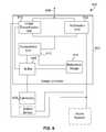
- FIG. 6is a block diagram of a visual monitoring system 600 according to an embodiment of the invention.
- the visual monitoring system 600is, for example, provided within the home location 102 to monitor one or more areas at the home location 102 .
- the visual monitoring system 600includes an image controller 602 and one or more cameras 604 .
- the camera(s) 604produce images of the areas being monitored.
- the image controller 602receives the images from the camera(s) 604 and controls the transmission of images to facilitate remote viewing of the images.
- the imagesare transmitted over a link 606 that couples the image controller 602 directly or indirectly to the Internet 104 .
- the link 606which couples the image controller 602 to the Internet 104 , may operate in conjunction with a modem that couples to a phone line or wireless modem for dial-up access to the Internet 104 via an Internet Service Provider (ISP).
- ISPInternet Service Provider
- the image controller 602includes a buffer 608 that receives and stores the images from the camera(s) 604 .
- a reference image storage 610stores one or more reference images. In general, the reference image storage 610 stores a reference image for each of the cameras (or areas monitored by the camera(s)). Hereafter, for ease of understanding, it is assume that there is a single camera which monitors a single area.
- a comparison unit 612compares the reference image from the reference image storage 610 with the current image from the buffer 608 to produce a comparison result.
- the comparison resultis forwarded to an image transmission unit 614 and a notification unit 616 .
- the image transmission unit 614operates to transmit the current image from the buffer 608 to the Internet 104 through the link 606 when the comparison result indicates an update condition.
- the motion detectors 617can also provide an indication of an update condition to the notification unit 616 .
- the image transmission unit 614operates to prevent the transmission of the current image from the buffer 608 to the Internet 104 when the comparison result does not indicate an update condition. Consequently, the image controller 602 is efficiently using the bandwidth of the communication connection to the Internet 104 because the current image is not transmitted unless the update condition has been detected.
- the notification unit 616is provided to notify an interested person of the update condition.
- the notification unit 616can notify the interested user, namely, telephone, cellular phone, pager, electronic mail (i.e., e-mail), facsimile, etc.
- the imagecan be transmitted as a file transfer over the Internet 104 and the interested person can be notified by pager.
- the imagecan be transmitted to a hosting Internet server, and the interested user is then able to view the image by accessing the Internet server via a web browser application program executing on a computer (e.g., remotely located computer).
- the transmission of the image and its notification for the interested usercan both be performed by sending an electronic mail message to the interested person, where the electronic mail message includes a textual, visual or audio notification and may have the image being transmitted as an attachment to the electronic mail message.
- the attached imageis thereafter able to be remotely viewed by the interested user by a variety of approaches.
- One approachis for the attached image to be launchable (automatically or manually) into a viewer.
- Another approachis for the interested user to start an application program which is able to display the image(s).
- Still another approachis for the computer system to display the image(s).
- Yet another approachis for the computer system receiving the electronic mail message to automatically display the incoming image on the display screen (e.g., within a window, border or screen saver of the display screen).
- the usermay chose to view the image in a number of formats, including, as a still JPEG picture, or a plurality of moving MPEG pictures.
- a still picturemay be selected through a graphical user interface control panel.
- the visual monitoring system 600may also include an alarm system 618 .
- the alarm system 618is an independent system that supplies an alarm signal to the image controller 602 when the alarm is activated (“tripped”).
- the image transmission unit 614 of the image controller 602may make use of the alarm signal in determining whether to transmit the current image.
- the notification unit 616 of the image controller 602may also utilize the alarm signal in determining whether to notify an interested person.
- the image transmission unit 614can operate to avoid transmission of images until the presence of the alarm signal, which advantageously reduces demands on bandwidth utilization.
- the imagescould be transmitted in accordance with the update condition without regard for the alarm signal so as to facilitate continuous remote viewing.
- the image controller 602can be implemented in a number of different ways.
- the image controller 602may be implemented by a general purpose computer.
- the image controller 602could be implemented by dedicated special purpose hardware.
- a home touch screenmay be mounted on a wall to allow, for example, a home owner to selectively enable or disable monitoring of selected rooms when the home owner is at home.
- FIGS. 7A and 7Bare diagrams illustrating a reference image 702 and a current image 704 .
- the current image 704contains a image of an intruder 706 , whereas the reference image 702 does not.
- the comparison of the reference image 702 to the current image 704can be performed in a number of ways.
- One way to compare the imagesis to compare intensity and/or color information of corresponding pixels. The number of pixels that differ by more than a minimal amount are deemed changed. Then, the total number of the changed pixels is compared against a predetermined threshold. When the total number of the changed pixels exceeds the predetermined amount, the update condition is present; otherwise, the update condition is not present.
- Another approachcould superimpose an imaginary grid 708 , 710 over the image and then produce an average intensity and/or color for each grid. Then, any of the grids having an average that differs by more than a threshold amount would cause the update condition to be present.
- FIG. 8is a flow diagram of local image processing 800 according to an embodiment of the invention.
- the local image processing 800is, for example, performed by the image controller 220 .
- the local image processing 800determines 802 whether an image has been received. More particularly, the image controller 220 determines whether an image has been received from the camera 222 . Next, the image received is stored 804 . The image received can be stored in any data storage device internal to or coupled to the image controller 220 or a computer implementing the image controller. A decision block 806 then determines whether an update condition is present. When the update condition is present, the image received is electronically transmitted 808 to a remote computer. The local image processing 800 then determines 810 whether notification has been requested. If it is determined that notification has been requested, then notification is provided 812 to an interested person. Following the decision block 810 directly when no notification is requested and following block 812 when notification has been requested, the local image processing 800 is complete and ends. Further, when the decision block 806 determines that the update condition is not present, then the local image processing 800 thereafter ends by bypassing blocks 808 - 812 .
- FIG. 9Ais a flow diagram of local image processing 900 according to another embodiment of the invention.
- the local image processing 900begins with a decision block 902 that determines whether the camera is active. If the camera is not active, then the local image processing 900 is complete and ends. On the other hand, when the camera is active, the local image processing 900 continues.
- the local image processing 900receives 904 an image from the camera. Then, the retrieved image is compared 906 with a reference image. Next, a decision block 908 determines whether the retrieved image is substantially different from the reference image. When the retrieved image is determined to be substantially different from the reference image, the retrieved image is compressed 910 . Thereafter, the compressed retrieved image is electronically transmitted 912 to a computer at a remote location. A decision block 914 then determines whether notification has been requested. Here, in one embodiment, the notification may be requested by the operator of a local computer at the home location 102 . When the decision block 914 determines that notification has been requested, then notification is provided 916 to a remote user. On the other hand, the block 916 is bypassed when notification is not requested.
- FIG. 9Bis a flow diagram of remote image processing 920 at a remote computer.
- the remote image processing 920is preferably performed by a remote computer, such as the computer 108 , the home monitor server 112 or the wireless computer 122 illustrated in FIG. 1 .
- the wireless computer 122may be hand held personal computer or organizer having a wireless modem link or cellular modem link.
- the remote image processing 920begins with a decision block 922 that determines whether a transmitted image has been received at the remote computer. When the decision block 922 determines that the transmitted image has not yet been received, then the remote image processing 920 waits until the reception of such image. Once the decision block 922 determines that the transmitted image has been received, then the remote image processing 920 continues.
- the received transmitted imageis stored 924 to data storage provided by the remote computer.
- decision block 926determines whether notification has been requested.
- the notificationis requested by the user of the remote computer in most cases, though others could also request the notification. If the decision block 926 determines that notification has been requested, then notification is provided 928 in the manner requested. Following the block 928 as well as following the decision block 926 when no notification is requested, the remote image processing 920 is complete and ends.
- FIG. 9Cis a flow diagram of view processing 940 at a remote computer.
- the remote computeras was the case in FIG. 8B , can be the computer 108 , the home monitor server 112 or the wireless computer 122 .
- the remote computer performing the view processing 940need not be the same remote computer performing the remote image processing 920 .
- the view processing 940begins with a decision block 942 that determines whether a view request has been received. Typically, the view request is generated manually by a user of the remote computer or automatically such as by the remote image processing. If the decision block 942 determines that a view request has not yet been received, then the view processing 940 waits until the reception of such a request. Once the decision block 942 determines that a view request has been received, the view processing 940 continues. The view processing 940 then selects 944 image(s) to be viewed 944 . Here, the user is able to preferably select one or more images to be concurrently viewed on a display device. Next, the selected image(s) are decompressed 946 .
- the imageswere initially stored in a compressed format. Of course, if the images are not being stored in a compressed form, there would be no need for decompression.
- the selected imagesare then displayed 948 on a display device. Following block 948 , the view processing 940 is complete and ends.
- the remote monitoring of locationscan not only provide efficient bandwidth utilization as noted above but also intelligent camera positioning or selection.
- locationse.g., a home, business, hospital room, daycare facility
- intelligent camera positioning or selectionFor example, if the schematic diagram 400 illustrated in FIG. 4 where to represent the internal layout of a location that provides daycare services, then the various areas (e.g., rooms but could also include external areas such as a playground area) could be monitored with a single camera. Alternatively, the various areas could be monitored using a plurality of cameras.
- the intelligent camera positioning or selectionthus allows a remote viewer to rapidly identify the particular one or more of the various areas being monitored that they desire to view using the images from the associated cameras.
- the intelligent selectionwill be described with reference to an example where the location is a daycare facility and a parent desires to remotely monitor their child's activities, behavior and treatment. With this example, then the parent remotely desiring to monitor their child has difficulty determining which the one or more cameras that depict their child at any given point in time because the child tends to move about at the daycare facility and thus frequently leaves the images of some cameras and comes into images of other cameras. It is therefore a time consuming task for a parent to constantly have to search for the appropriate camera that is capturing the images of their child.
- the intelligent camera selection offered by one aspect of the inventioneliminates this burden from the parent by automatically determining an appropriate camera for a particular remote viewer (e.g., parent).
- One wayis to have the remote viewer initially identify their child, then the monitoring system tracks the identified child about the location and automatically select the most appropriate view for the remote viewer to watch. The tracking could be performed by requiring the children at the location to wear different colors, and then the monitoring system is able to track the children by color.
- Another way to perform the trackingis to have the children carry radio transmitters with distinctive frequencies or data identifiers, and for the monitoring system to include one or more receivers to locate the most appropriate camera based on the strength of the signals or be a triangulation technique.
- the transmitterscan be small low power devices than transmit a short burst of information every so often (e.g., every 1-5 minutes).
- Still another wayis for the children to include Global Positioning System devices to location their global position, and then transmitting data (by any of a variety of ways) of their global position to the monitoring system which then in turn identifies the most appropriate camera view for an identified child.
- the remote viewerwould normally still be allowed to manually select an area or view to monitor if so desired.
- the monitoring systemcan also be used to track other individuals or animals in similar ways.
- imageswere obtained from cameras and transmitted. These images can refer to still camera images, video images, and the like.
- the format of the imagescan also take many form, namely JPEG, PICT, TIF, MPEG, etc.
- audio informationmay also be provided to the remote viewer apart or together with the images.
- the notifications provided to a remote user or interested personcan be achieved in a variety of ways.
- the notificationcan be by telephone (wired or cellular), paging, electronic mail, or Internet notifications.
- the telephone notificationcan play a message
- the pagercan display a message
- the electronic mail messagecan contain a text, audio and/or visual message.
- the Internet notificationscan use “push” technology to notify or forward images to a remote user or interested person. “Push” technology is, for example, described in PC Magazine, vol. 16, no. 11, pp. 156-180 (1997) which is hereby incorporated by reference.
- the inventionalso relates to remote monitoring and controlling of devices or appliances.
- the information appliancesare located in, for example, the home location 102 , and the remote monitoring is facilitated by the Internet 104 such that a remote user at a remote computer is able to both monitor and control information appliances at the home location 102 using the Internet 104 .
- the processing carried out at the local machine and the remote machineare described below for embodiments of the invention.
- FIGS. 10A and 10Bare flow diagrams of remote request processing 1000 according to an embodiment of the invention.
- the remote request processing 1000begins by displaying 1002 a status request form on a display for the remote computer.
- the user of the remote computercompletes 1004 the status request form so as to indicate the particular information appliances for which status information is desired.
- the usermay request status information for an alarm system, VCR, digital TV programming or other home entertainment controls, home utilities including lighting, heating, cooling, sprinkler system, and the like.
- the completed status request formis then sent 1006 to a local computer.
- a decision block 1008determines whether a reply message has been received from the local computer in response to the completed status request form. If the reply message has not been received, the remote request processing 1000 awaits its receipt. Once the reply message has been received, the remote request processing 1000 continues.
- the reply messageis parsed 1010 for the status information.
- the status information formis displayed 1012 at the remote computer.
- the status informationis presented to the user at the remote computer in the status information form that is displayed at the remote computer.
- the status information formis a window of a graphical user interface that displays the status information for the various information appliances in a manner that is easily understood by the user.
- a decision block 1014determines whether control is requested.
- the remote request processing 1000determines whether the user also desires to control one or more of the information appliances associated with the system. If the remote user does not wish to control any of the information appliances, the remote request processing is complete and ends.
- the remote request processingcontinues.
- the control request formis then displayed 1016 at the remote computer.
- the usercompletes 1018 the control request form.
- the usercompletes the control request form so as to indicate the actions the user desires for particular information appliances. For example, the user may request the control to adjust the temperature control to 60 degrees F., or turn-on certain lights, or reset the VCR or digital TV for recording certain channels.
- the completed control request formis then sent 1020 to the local computer.
- a decision block 1022determines whether a confirmation has been received from the local computer. If a confirmation has not yet been received, the remote request processing 1000 awaits its reception. If the confirmation is not received in a predetermined amount of time, the remote request processing 1000 could operate to notify the remote user that the control requested for the particular information appliance has not been confirmed. In any event, when confirmation is received, the remote request processing 1000 is complete and ends.
- the confirmationmay be eliminated or bypassed by a user.
- the confirmationcan be of different types, for example, confirm its transmission, confirm its receipt, confirm that the information appliance understands the requests, or confirm that the information appliance has complied with the request.
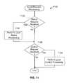
- FIG. 11is a flow diagram of local request processing 1100 according to an embodiment of the invention.
- the local request processing 1100is for example performed by a computer at the home location 102 .
- the local request processing 1100begins with a decision block 1102 that determines whether a status request has been received. If a status request has been received at the local computer, local status processing is performed 1104 . The local status processing is described in detail below with respect to FIG. 12 .
- the decision block 1102determines that a status request has not been received, or following the performance of the local status processing 1104 when a status request has been received, a decision block 1106 determines whether a control request has been received. If a control request has been received, local control processing is performed 1108 . The local control processing is described in detail below with respect to FIG. 13 .
- the local request processing 1100is complete and ends.
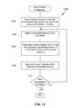
- FIG. 12is a flow diagram of local status processing 1200 according to an embodiment of the invention.
- the local status processing 1200is, for example, performed by the block 1104 in FIG. 11 .
- the local status processing 1200initially parses 1202 the status request to identify requested status information.
- the requested status informationidentifies the particular status information that the remote user is requesting.
- the requested status informationis retrieved 1204 from data storage to the extent available.
- the data storagecould be the data memory storage associated with the local computer.
- the local computermay periodically poll or otherwise track the status of certain information appliances and maintains such information in data storage (e.g., disk drive or main memory).
- a decision block 1206determines whether additional information is needed. In other words, the decision block 1206 determines whether additional information is needed after the local status processing 1200 has attempted to retrieve the requested status information from the data storage. If additional information is still needed, information appliances are polled 1208 as needed to obtain the additional information needed. On the other hand, if the decision block 1206 determines that additional information is not needed, the block 1208 is bypassed. Next, a reply message is formulated 1210 . The reply message is then sent 1212 to the remote computer. Following block 1212 , the local status processing 1200 is complete and ends.
- FIG. 13is a flow diagram of local control processing 1300 according to an embodiment of the invention.
- the local control processing 1300is, for example, the processing performed by the block 1108 in FIG. 11 .
- the local control processing 1300initially parses 1302 the control request to identify the one or more information appliances to be controlled as well as control actions for each of the information appliances to be controlled.
- the information appliance being controlledmight be an air conditioning unit, and the control action might be to cool the home to 65 degrees F.
- the informationis a VCR or digital TV and the control actions can be to record channel 7 from 8:00 to 10:00 p.m. on a VCR tape or a digital TV buffer.
- the information applianceis a view monitoring system and the control action could be to turn-on.
- one of the identified information appliances to be controlledis selected 1304 .
- control signals to stimulate the selected information appliance to carry out the requested control actionsare formulated 1306 .
- the control signalsare then sent 1308 to the selected information appliance.
- the manner with which the control signals are sent 1308can vary from appliance to appliance, and might include light beams (infrared light, ultraviolet light), radio waves, or electrically conductive wires.
- a decision block 1310determines whether there are more information appliances are to be controlled. If the control request identifies other information appliances to be controlled, then the decision block 1310 causes the local control processing 1300 to return to repeat blocks 1304 through 1310 for another of the information appliances identified by the control request. On the other hand, when the decision block 1310 determines that all the identified information appliances to be controlled have been processed, then the local control processing 1300 is complete and ends.
- FIG. 14is a graphical user interface (GUI) window 1400 for a remote computer according to an embodiment of the invention.
- GUIgraphical user interface
- the GUI window 1400is suitable for implementing the displaying of the images at a remote location via the view processing 940 .
- the GUI window 1400is a representative window for a camera surveillance system for a home.
- the GUI window 1400illustrates program viewing settings 1402 which operate to select the location within the home that the user of the remote computer desires to view remotely.
- the GUI window 1400also includes a viewing window 1404 that displays the image(s) of the selected location.
- the GUI window 1400may include a pair of panning control icons 1416 , and a pair of tilting control icons 1418 for real-time control of the camera from a remotely networked computer.
- the usermay modify the size of the viewing window 1404 by simply dragging out a corner of the viewing window 1404 .
- the GUI window 1400may be modified to display multiple rooms or locations on one screen.
- FIG. 15is another GUI window 1500 for a remote computer according to an embodiment of the invention.
- the GUI window 1500is suitable for implementing the displaying of the images at a remote location via the remote request processing 1000 .
- the GUI window 1500is a representative window for an appliance monitoring and control system for a home.
- the GUI window 1500can display either the status information form ( 1012 ) or the control request form ( 1016 ) for devices or appliances in a home, including home security, home utilities, and home entertainment.
- the GUI window 1500can further include an area facilitating a user's selection of notification request options, thus allowing the user to easily alter the type and frequency of notification received from a remote location.
- the remote useris able to turn on or off the home cam (i.e., camera apparatus 402 of FIG. 4 ) from a remotely networked computer system.
- the home cami.e., camera apparatus 402 of FIG. 4
- the usermay log on to the Internet 104 and access GUI window 1500 through a browser.
- the home ownermay desire wish to view video clips of a security breach that may have occurred in the living room.
- the usermay simply click on the “view security breach” icon which links the home owner to a GUI window 1600 of FIG. 16 below.
- GUI window 1500the home owner may be provided with a variety of utility controls.
- the utility controlsmay include controls for temperature of selected rooms, lighting of selected rooms, and watering of gardens for selected periods of time.
- a home entertainment control panelIn the rightmost portion of GUI window 1500 is a home entertainment control panel.
- This control panelmay be linked to one or more VCRs or a digital TV having an internal buffer for digitally storing broadcast shows, news clips, or movies from a remote location.
- the buffermay be partitioned into multiple segments that may be re-written continuously for a selected channel after a predetermined period of time lapses (i.e., depending on buffer sizes).
- the home ownermay simply log onto the Internet, enter a password to access the custom GUI window 1500 for the homeowner, and then program the desired viewing channels, recording times, and dates.
- FIG. 16is a GUI window 1600 suitable for displaying on a remote computer screen according to an embodiment of the invention.
- the GUI window 1600indicates to a remotely located interested person an alarm condition of a home location.
- the GUI window 1600includes a security system status area 1602 that displays the status of various devices of an alarm system, including door sensors, motion sensors, cameras, and switches.
- the GUI window 1600also includes an image viewer 1604 for displaying an image or series of images.
- the living room motion sensor and the living room cameraboth indicate that they have caused an alarm condition.
- the image viewer 1604can automatically display the most appropriate images with respect to the alarm condition, e.g., the living room, and/or could allow the user to select an image from a list of available images.
- the alarm conditioncaused the alarm system to forward this status information and/or image to a user of a remote computer in the various ways previously described.
- FIG. 17is a GUI window 1700 suitable for displaying on a remote computer screen according to another embodiment of the invention.
- the GUI window 1700indicates to a remotely located interested person patient information such as for a patient in a hospital or nursing home.
- the GUI window 1700includes a patient status information area 1702 that displays the status of various patient monitoring equipment, patient vitals, and care provided to patient (e.g., meals, bathing, etc.).
- the patient status area 1702also illustrates patient selection details for the remote user to specify the hospital (nursing home), room (or patient) and a password so as to verify that the remote user has access privileged to view the particular room (and patient).
- the GUI window 1700also includes an image viewer 1704 for displaying an image or series of images.
- the imageis of a bed that is typically provided in a room of a hospital or nursing home.
- a control panel 1706enables the remote user to start, stop, fast forward, rewind, and pause a video clip, or change still images being displayed in the image viewer 1704 .
- the image displayed in the image viewer 1704indicates another camera (CAM 1 ) in the back area of the room.
- the control panelwould allow the remote user to select the images from the CAM 1 for display in the viewer window 1704 .
- GUI window 1708may further include a camera (CAM) control panel 1708 that enables the remote user to control the camera positioning in the room from remote location so as to obtain the view within the room desired.
- the remote computer displaying the GUI window 1700could also provide alerts (e.g., notifications) to the remote user. The alerts would be electronically transmitted and these alerts could then be obtained remotely by the remote user and perhaps displayed on the remote computer similar to that illustrated in FIG. 16 with respect to an alarm system. Other types of notifications such as discussed above for other embodiments are also possible.
- the above-described embodimentscan also provide audio monitoring together with the video monitoring.
- the audiocan be part of the video clip.
- audio from the monitored locationcan also be transmitted to the intermediate server computer or to a user's remote computer.
- the audiocan be sent in a streaming fashion for a real-time audio effect, or can be sent periodically, or can be send when an alarm or update condition is detected.
- the amount of audio saved and/or transmittedcan be reduced by saving or transmitting audio data pertaining to alarm or update conditions. For example, the system could start to save and/or transmit audio data occurring just before the alarm or update condition and then continue up until some time after the alarm or update condition.
- the monitoring, detecting and controllingcan also be provided in a two-way manner.
- visual (and perhaps audio)can be made available to user's at the local location and the remote location.
- a patientcan not only see but also speak with the remote user and vice versa.
- a person or animal at a home location being monitoredcan communicate (e.g., see and/or hear) with the remote user. The communications had can also be in nearly real-time.
- the inventioncan also be embodied as computer readable code on a computer readable medium.
- the computer readable mediumis any data storage device that can store data which can be thereafter be read by a computer system. Examples of the computer readable medium include read-only memory, random-access memory, CD-ROMs, magnetic tape, optical data storage devices, and networks. In the case of networks, computer readable medium includes a wired or wireless link over which the computer readable code is transmitted with electrical signals.
- the computer readable codecan also be distributed over network coupled computer systems so that the computer readable code is stored and executed in a distributed fashion.
Landscapes
- Engineering & Computer Science (AREA)
- Computer Networks & Wireless Communication (AREA)
- Signal Processing (AREA)
- Automation & Control Theory (AREA)
- Medical Informatics (AREA)
- General Health & Medical Sciences (AREA)
- Computing Systems (AREA)
- General Engineering & Computer Science (AREA)
- Physics & Mathematics (AREA)
- General Physics & Mathematics (AREA)
- Health & Medical Sciences (AREA)
- Telephonic Communication Services (AREA)
- Alarm Systems (AREA)
- Closed-Circuit Television Systems (AREA)
- Selective Calling Equipment (AREA)
Abstract
Description
Claims (28)
Priority Applications (8)
| Application Number | Priority Date | Filing Date | Title |
|---|---|---|---|
| US11/115,021US8073921B2 (en) | 1997-07-01 | 2005-04-25 | Methods for remote monitoring and control of appliances over a computer network |
| US13/165,718US20110252444A1 (en) | 1997-07-01 | 2011-06-21 | Television System Having Digital Buffers for Programming |
| US13/177,934US20110261206A1 (en) | 1997-07-01 | 2011-07-07 | Internet surveillance system and remote control of networked devices |
| US13/195,777US20110285852A1 (en) | 1997-07-01 | 2011-08-01 | Methods and remote monitoring and control of appliances over a computer network |
| US13/312,050US20120159597A1 (en) | 1997-07-01 | 2011-12-06 | Methods for remote monitoring and control of security devices over a computer network |
| US13/443,787US20120198533A1 (en) | 1997-07-01 | 2012-04-10 | Methods for remote monitoring and control of home devices over a computer network |
| US13/455,097US20120207445A1 (en) | 1997-07-01 | 2012-04-24 | Methods for remote access and control of television programming from a wireless portable device |
| US13/545,484US20120274791A1 (en) | 1997-07-01 | 2012-07-10 | Methods for processing notifications to hand held computing devices for a connected home |
Applications Claiming Priority (3)
| Application Number | Priority Date | Filing Date | Title |
|---|---|---|---|
| US5148997P | 1997-07-01 | 1997-07-01 | |
| US9827998A | 1998-06-16 | 1998-06-16 | |
| US11/115,021US8073921B2 (en) | 1997-07-01 | 2005-04-25 | Methods for remote monitoring and control of appliances over a computer network |
Related Parent Applications (1)
| Application Number | Title | Priority Date | Filing Date |
|---|---|---|---|
| US9827998ADivision | 1997-07-01 | 1998-06-16 |
Related Child Applications (5)
| Application Number | Title | Priority Date | Filing Date |
|---|---|---|---|
| US13/165,718ContinuationUS20110252444A1 (en) | 1997-07-01 | 2011-06-21 | Television System Having Digital Buffers for Programming |
| US13/177,934ContinuationUS20110261206A1 (en) | 1997-07-01 | 2011-07-07 | Internet surveillance system and remote control of networked devices |
| US13/195,777ContinuationUS20110285852A1 (en) | 1997-07-01 | 2011-08-01 | Methods and remote monitoring and control of appliances over a computer network |
| US13/312,050ContinuationUS20120159597A1 (en) | 1997-07-01 | 2011-12-06 | Methods for remote monitoring and control of security devices over a computer network |
| US13/312,050DivisionUS20120159597A1 (en) | 1997-07-01 | 2011-12-06 | Methods for remote monitoring and control of security devices over a computer network |
Publications (2)
| Publication Number | Publication Date |
|---|---|
| US20050198063A1 US20050198063A1 (en) | 2005-09-08 |
| US8073921B2true US8073921B2 (en) | 2011-12-06 |
Family
ID=46304424
Family Applications (4)
| Application Number | Title | Priority Date | Filing Date |
|---|---|---|---|
| US11/115,021Expired - Fee RelatedUS8073921B2 (en) | 1997-07-01 | 2005-04-25 | Methods for remote monitoring and control of appliances over a computer network |
| US13/165,718AbandonedUS20110252444A1 (en) | 1997-07-01 | 2011-06-21 | Television System Having Digital Buffers for Programming |
| US13/177,934AbandonedUS20110261206A1 (en) | 1997-07-01 | 2011-07-07 | Internet surveillance system and remote control of networked devices |
| US13/195,777AbandonedUS20110285852A1 (en) | 1997-07-01 | 2011-08-01 | Methods and remote monitoring and control of appliances over a computer network |
Family Applications After (3)
| Application Number | Title | Priority Date | Filing Date |
|---|---|---|---|
| US13/165,718AbandonedUS20110252444A1 (en) | 1997-07-01 | 2011-06-21 | Television System Having Digital Buffers for Programming |
| US13/177,934AbandonedUS20110261206A1 (en) | 1997-07-01 | 2011-07-07 | Internet surveillance system and remote control of networked devices |
| US13/195,777AbandonedUS20110285852A1 (en) | 1997-07-01 | 2011-08-01 | Methods and remote monitoring and control of appliances over a computer network |
Country Status (1)
| Country | Link |
|---|---|
| US (4) | US8073921B2 (en) |
Cited By (26)
| Publication number | Priority date | Publication date | Assignee | Title |
|---|---|---|---|---|
| US20050105881A1 (en)* | 1993-03-05 | 2005-05-19 | Gemstar Development Corporation. | System and method for searching a database of television schedule information |
| US20080189737A1 (en)* | 1998-07-17 | 2008-08-07 | Ellis Michael D | Interactive television program guide system having multiple devices within a household |
| US20080247730A1 (en)* | 2000-03-02 | 2008-10-09 | Barton James M | System and method for internet access to a personal television service |
| US20100333151A1 (en)* | 2009-06-30 | 2010-12-30 | Gemstar Development Corporation | Cross platform entertainment architecture |
| US20110078715A1 (en)* | 2009-09-29 | 2011-03-31 | Rovi Technologies Corporation | Identifying a movie of interest from a widget used with movie commericials |
| US20110254955A1 (en)* | 2010-04-18 | 2011-10-20 | Peter Chi-Chen Shen | Detachable Universal Electronic Door Viewer |
| US20120065749A1 (en)* | 2010-09-13 | 2012-03-15 | Motorola Mobility, Inc. | Display of Devices on an Interface based on a Contextual Event |
| US20120130513A1 (en)* | 2010-11-18 | 2012-05-24 | Verizon Patent And Licensing Inc. | Smart home device management |
| US8528032B2 (en) | 1998-07-14 | 2013-09-03 | United Video Properties, Inc. | Client-server based interactive television program guide system with remote server recording |
| US8578413B2 (en) | 1998-07-17 | 2013-11-05 | United Video Properties, Inc. | Interactive television program guide with remote access |
| US20140140355A1 (en)* | 2012-11-20 | 2014-05-22 | General Electric Company | Using a rest resource base for networked appliances |
| US8806533B1 (en) | 2004-10-08 | 2014-08-12 | United Video Properties, Inc. | System and method for using television information codes |
| US8892495B2 (en) | 1991-12-23 | 2014-11-18 | Blanding Hovenweep, Llc | Adaptive pattern recognition based controller apparatus and method and human-interface therefore |
| US20150156074A1 (en)* | 2013-03-08 | 2015-06-04 | Panasonic Intellectual Property Corporation Of America | Information sharing method |
| US9071872B2 (en) | 2003-01-30 | 2015-06-30 | Rovi Guides, Inc. | Interactive television systems with digital video recording and adjustable reminders |
| US9125169B2 (en) | 2011-12-23 | 2015-09-01 | Rovi Guides, Inc. | Methods and systems for performing actions based on location-based rules |
| US9294799B2 (en) | 2000-10-11 | 2016-03-22 | Rovi Guides, Inc. | Systems and methods for providing storage of data on servers in an on-demand media delivery system |
| US9307281B2 (en) | 2007-03-22 | 2016-04-05 | Rovi Guides, Inc. | User defined rules for assigning destinations of content |
| US9535563B2 (en) | 1999-02-01 | 2017-01-03 | Blanding Hovenweep, Llc | Internet appliance system and method |
| US9635323B2 (en) | 2002-10-15 | 2017-04-25 | Eyetalk365, Llc | Communication and monitoring system |
| US10063934B2 (en) | 2008-11-25 | 2018-08-28 | Rovi Technologies Corporation | Reducing unicast session duration with restart TV |
| US20190188993A1 (en)* | 2009-01-06 | 2019-06-20 | Vetrix, Llc | Integrated physical and logical security management via a portable device |
| EP3086577B1 (en) | 2013-12-20 | 2020-07-01 | Samsung Electronics Co., Ltd. | Method and device for event notification in home network system |
| US20210329463A1 (en)* | 2017-04-07 | 2021-10-21 | Noritz Corporation | Communication system |
| US11438732B2 (en) | 2009-03-06 | 2022-09-06 | Vetrix, Llc | Systems and methods for mobile tracking, communications and alerting |
| US11710103B2 (en) | 2016-03-21 | 2023-07-25 | Carrier Corporation | Intrusion security panel with remote assistance through simulated user interface |
Families Citing this family (107)
| Publication number | Priority date | Publication date | Assignee | Title |
|---|---|---|---|---|
| US8464359B2 (en)* | 1997-11-03 | 2013-06-11 | Intellectual Ventures Fund 30, Llc | System and method for obtaining a status of an authorization device over a network |
| US7688952B2 (en)* | 1997-11-03 | 2010-03-30 | Light Elliott D | System and method for obtaining equipment status data over a network |
| US7088802B2 (en)* | 1997-11-03 | 2006-08-08 | Light Elliott D | Method and apparatus for obtaining telephone status over a network |
| US7529350B2 (en)* | 1997-11-03 | 2009-05-05 | Light Elliott D | System and method for obtaining equipment status data over a network |
| US6697103B1 (en) | 1998-03-19 | 2004-02-24 | Dennis Sunga Fernandez | Integrated network for monitoring remote objects |
| US20030025599A1 (en)* | 2001-05-11 | 2003-02-06 | Monroe David A. | Method and apparatus for collecting, sending, archiving and retrieving motion video and still images and notification of detected events |
| US7543325B2 (en) | 1999-03-30 | 2009-06-02 | Tivo Inc. | System for remotely controlling client recording and storage behavior |
| DE19934787B4 (en)* | 1999-07-27 | 2004-08-05 | T-Mobile Deutschland Gmbh | Method for automatically adapting the data to be transmitted from a data providing device to a data retrieving device to the capabilities of this terminal |
| US6803945B1 (en)* | 1999-09-21 | 2004-10-12 | Intel Corporation | Motion detecting web camera system |
| US20030182567A1 (en) | 1999-10-20 | 2003-09-25 | Tivo Inc. | Client-side multimedia content targeting system |
| US8578439B1 (en)* | 2000-01-28 | 2013-11-05 | Koninklijke Philips N.V. | Method and apparatus for presentation of intelligent, adaptive alarms, icons and other information |
| GB0005026D0 (en)* | 2000-03-03 | 2000-04-26 | Hewlett Packard Co | Generating and logging reminders whilst mobile |
| US20020065927A1 (en)* | 2000-09-05 | 2002-05-30 | Janik Craig M. | Webpad and method for using the same |
| US20050146605A1 (en)* | 2000-10-24 | 2005-07-07 | Lipton Alan J. | Video surveillance system employing video primitives |
| US8564661B2 (en) | 2000-10-24 | 2013-10-22 | Objectvideo, Inc. | Video analytic rule detection system and method |
| US9892606B2 (en)* | 2001-11-15 | 2018-02-13 | Avigilon Fortress Corporation | Video surveillance system employing video primitives |
| US8711217B2 (en) | 2000-10-24 | 2014-04-29 | Objectvideo, Inc. | Video surveillance system employing video primitives |
| US6892546B2 (en) | 2001-05-03 | 2005-05-17 | Emerson Retail Services, Inc. | System for remote refrigeration monitoring and diagnostics |
| US6668240B2 (en) | 2001-05-03 | 2003-12-23 | Emerson Retail Services Inc. | Food quality and safety model for refrigerated food |
| US20030037341A1 (en)* | 2001-08-17 | 2003-02-20 | Van Der Meulen Pieter Sierd | System for remotely controlling consumer electronics using a web-cam image |
| US7310344B1 (en)* | 2001-12-28 | 2007-12-18 | Cisco Technology, Inc. | Method and system for an instant messenger home automation system interface using a home router |
| US20040056953A1 (en)* | 2002-09-20 | 2004-03-25 | Crandall John Christopher | System and method for controlling service delivery |
| US6889173B2 (en) | 2002-10-31 | 2005-05-03 | Emerson Retail Services Inc. | System for monitoring optimal equipment operating parameters |
| JP3883955B2 (en)* | 2002-11-25 | 2007-02-21 | 株式会社日立製作所 | Network system, management device, information device and program |
| US7088238B2 (en)* | 2002-12-11 | 2006-08-08 | Broadcom, Inc. | Access, monitoring, and control of appliances via a media processing system |
| US20060155851A1 (en)* | 2003-11-25 | 2006-07-13 | Matsushita Electric Industrial Co., Ltd. | Networked home surveillance architecture for a portable or remote monitoring device |
| US7640066B2 (en)* | 2004-02-05 | 2009-12-29 | York International Corporation | Transport of encapsulated serial data via instant messaging communication |
| US7183899B2 (en)* | 2004-03-15 | 2007-02-27 | Global Gate Technologies, Inc. | Remotely monitored and controlled building automation system |
| US7412842B2 (en) | 2004-04-27 | 2008-08-19 | Emerson Climate Technologies, Inc. | Compressor diagnostic and protection system |
| US7275377B2 (en) | 2004-08-11 | 2007-10-02 | Lawrence Kates | Method and apparatus for monitoring refrigerant-cycle systems |
| JP2006155522A (en) | 2004-12-01 | 2006-06-15 | Canon Inc | WEB browser operation method and operation device |
| ATE553422T1 (en)* | 2005-02-21 | 2012-04-15 | Computer Process Controls Inc | CONTROL AND MONITORING SYSTEM FOR COMPANIES |
| US8237801B2 (en) | 2005-08-05 | 2012-08-07 | The Innovation Science Fund I, LLC | Image processing system and communication method |
| US8688804B2 (en)* | 2005-09-26 | 2014-04-01 | Samsung Electronics Co., Ltd. | Apparatus and method for transmitting sound information in web-based control system |
| US7752854B2 (en) | 2005-10-21 | 2010-07-13 | Emerson Retail Services, Inc. | Monitoring a condenser in a refrigeration system |
| US7752853B2 (en)* | 2005-10-21 | 2010-07-13 | Emerson Retail Services, Inc. | Monitoring refrigerant in a refrigeration system |
| KR20070044321A (en)* | 2005-10-24 | 2007-04-27 | 삼성전자주식회사 | Display device and network system including same |
| US7504942B2 (en)* | 2006-02-06 | 2009-03-17 | Videoiq, Inc. | Local verification systems and methods for security monitoring |
| US7966083B2 (en) | 2006-03-16 | 2011-06-21 | Exceptional Innovation Llc | Automation control system having device scripting |
| US7496627B2 (en) | 2006-03-16 | 2009-02-24 | Exceptional Innovation, Llc | Automation control system having digital logging |
| US8001219B2 (en) | 2006-03-16 | 2011-08-16 | Exceptional Innovation, Llc | User control interface for convergence and automation system |
| US7587464B2 (en) | 2006-03-16 | 2009-09-08 | Exceptional Innovation, Llc | Device automation using networked device control having a web services for devices stack |
| US8725845B2 (en) | 2006-03-16 | 2014-05-13 | Exceptional Innovation Llc | Automation control system having a configuration tool |
| US8209398B2 (en) | 2006-03-16 | 2012-06-26 | Exceptional Innovation Llc | Internet protocol based media streaming solution |
| US7509402B2 (en) | 2006-03-16 | 2009-03-24 | Exceptional Innovation, Llc | Automation control system having a configuration tool and two-way ethernet communication for web service messaging, discovery, description, and eventing that is controllable with a touch-screen display |
| US8155142B2 (en) | 2006-03-16 | 2012-04-10 | Exceptional Innovation Llc | Network based digital access point device |
| WO2007126781A2 (en) | 2006-03-27 | 2007-11-08 | Exceptional Innovation Llc | Set top box for convergence and automation system |
| US8271881B2 (en) | 2006-04-20 | 2012-09-18 | Exceptional Innovation, Llc | Touch screen for convergence and automation system |
| US7667968B2 (en) | 2006-05-19 | 2010-02-23 | Exceptional Innovation, Llc | Air-cooling system configuration for touch screen |
| US8590325B2 (en) | 2006-07-19 | 2013-11-26 | Emerson Climate Technologies, Inc. | Protection and diagnostic module for a refrigeration system |
| WO2008022322A2 (en)* | 2006-08-17 | 2008-02-21 | Vantage Controls, Inc. | System and method for creating a user interface |
| US20080216494A1 (en) | 2006-09-07 | 2008-09-11 | Pham Hung M | Compressor data module |
| WO2008073658A2 (en) | 2006-11-09 | 2008-06-19 | Exceptional Innovation, Llc. | Portable device for convergence and automation solution |
| JP4894549B2 (en)* | 2007-02-19 | 2012-03-14 | 株式会社ニコン | Server device |
| US20090037142A1 (en) | 2007-07-30 | 2009-02-05 | Lawrence Kates | Portable method and apparatus for monitoring refrigerant-cycle systems |
| US9140728B2 (en) | 2007-11-02 | 2015-09-22 | Emerson Climate Technologies, Inc. | Compressor sensor module |
| US8413204B2 (en) | 2008-03-31 | 2013-04-02 | At&T Intellectual Property I, Lp | System and method of interacting with home automation systems via a set-top box device |
| US8844200B2 (en)* | 2008-04-02 | 2014-09-30 | Globe Motors, Inc. | Electrical door operator |
| US8261491B2 (en) | 2008-04-02 | 2012-09-11 | Leon Yulkowski | Concealed electrical door operator |
| CN101753991A (en)* | 2008-12-17 | 2010-06-23 | 德昌电机(深圳)有限公司 | Remote wireless monitoring system, monitoring device and monitoring method |
| US20100204950A1 (en)* | 2009-02-10 | 2010-08-12 | Sony Corporation | Automated test for consumer electronics |
| US20100262403A1 (en)* | 2009-04-10 | 2010-10-14 | Bradford White Corporation | Systems and methods for monitoring water heaters or boilers |
| MX2011012546A (en) | 2009-05-29 | 2012-10-03 | Emerson Retail Services Inc | System and method for monitoring and evaluating equipment operating parameter modifications. |
| US8653982B2 (en)* | 2009-07-21 | 2014-02-18 | Openings | Door monitoring system |
| US9201143B2 (en) | 2009-08-29 | 2015-12-01 | Echo-Sense Inc. | Assisted guidance navigation |
| KR20110069574A (en)* | 2009-12-17 | 2011-06-23 | 엘지전자 주식회사 | A control method for an electric appliance having a detachable communication modem |
| US9246915B2 (en)* | 2010-03-19 | 2016-01-26 | Appbanc, Llc | Streaming media for portable devices |
| US8812656B2 (en) | 2010-04-12 | 2014-08-19 | Broadcom Corporation | System and method for automatically managing a network of user-selectable devices |
| KR100991253B1 (en)* | 2010-05-07 | 2010-11-01 | (주)넥스트로닉스 | Position tracking device |
| US20130207812A1 (en)* | 2010-08-16 | 2013-08-15 | Siemens Healthcare Diagnostics Inc. | Method and Device for Optical Alert Recognition |
| US20130155245A1 (en)* | 2010-08-27 | 2013-06-20 | Milan Slamka | System For Remote Communications Between Scout And Monitor |
| KR101721225B1 (en)* | 2010-09-28 | 2017-03-29 | 삼성전자주식회사 | Method for controlling device, device control apparatus, and computer readable storage medium |
| KR101219904B1 (en)* | 2010-11-12 | 2013-01-08 | 현대자동차주식회사 | Vehicle Network System interconnecting Home Network |
| WO2012068280A1 (en) | 2010-11-16 | 2012-05-24 | Echo-Sense Inc. | Remote guidance system |
| CA2934860C (en) | 2011-02-28 | 2018-07-31 | Emerson Electric Co. | Residential solutions hvac monitoring and diagnosis |
| US8483665B2 (en)* | 2011-03-31 | 2013-07-09 | Matthew R. Kissinger | Mobile device featuring sensor responsive re-notifications |
| TWI433568B (en)* | 2011-05-05 | 2014-04-01 | Univ Nat Taiwan Science Tech | Human-environment interactive system and portable device using the same |
| US9081942B2 (en) | 2011-06-09 | 2015-07-14 | Microsoft Technology Licensing, LLP. | Use of user location information for remote actions |
| JP6008564B2 (en)* | 2011-06-20 | 2016-10-19 | 三菱電機株式会社 | Air conditioner |
| US8964338B2 (en) | 2012-01-11 | 2015-02-24 | Emerson Climate Technologies, Inc. | System and method for compressor motor protection |
| EP2891299B1 (en)* | 2012-08-28 | 2018-08-15 | UTC Fire & Security Americas Corporation, Inc. | Systems and methods for efficient remote security panel configuration and management |
| US20160164976A1 (en)* | 2012-09-24 | 2016-06-09 | Suitable Technologies, Inc. | Systems and methods for remote presence |
| US9310439B2 (en) | 2012-09-25 | 2016-04-12 | Emerson Climate Technologies, Inc. | Compressor having a control and diagnostic module |
| WO2014160519A1 (en)* | 2013-03-13 | 2014-10-02 | Eddins Scott | Color-changing lighting dynamic control |
| EP2971989A4 (en) | 2013-03-15 | 2016-11-30 | Emerson Electric Co | DIAGNOSTICS AND SYSTEM FOR HEATING, VENTILATION AND AIR CONDITIONING REMOTE MONITORING |
| US9551504B2 (en) | 2013-03-15 | 2017-01-24 | Emerson Electric Co. | HVAC system remote monitoring and diagnosis |
| EP2972902B1 (en) | 2013-03-15 | 2019-10-02 | Hayward Industries, Inc. | Modular pool/spa control system |
| US9803902B2 (en) | 2013-03-15 | 2017-10-31 | Emerson Climate Technologies, Inc. | System for refrigerant charge verification using two condenser coil temperatures |
| WO2014165731A1 (en) | 2013-04-05 | 2014-10-09 | Emerson Electric Co. | Heat-pump system with refrigerant charge diagnostics |
| US20150116507A1 (en)* | 2013-10-25 | 2015-04-30 | Ciil Technologies, Llc | Monitoring system for an outdoor display |
| WO2015063000A1 (en)* | 2013-11-04 | 2015-05-07 | Koninklijke Philips N.V. | Method of notifying a user on a task on an apparatus |
| US10378262B2 (en) | 2014-10-23 | 2019-08-13 | Leon Yulkowski | Door operator and clutch |
| US10593190B2 (en)* | 2014-12-30 | 2020-03-17 | Google Llc | Systems and methods of providing status information in a smart home security detection system |
| US9727046B2 (en)* | 2015-02-19 | 2017-08-08 | Gangming Luo | System for monitoring or controlling a remote programmable device by configuring a reconfigurabale record stored on a server by a local computing device |
| US11255479B2 (en) | 2015-04-29 | 2022-02-22 | Condux International, Inc. | System and method of mapping a duct |
| WO2016176693A1 (en)* | 2015-04-29 | 2016-11-03 | Inception Innovations, Llc | Color-changing lighting dynamic control |
| US10212359B2 (en)* | 2015-12-30 | 2019-02-19 | Cerner Innovation, Inc. | Camera normalization |
| US20170211285A1 (en) | 2016-01-22 | 2017-07-27 | Hayward Industries, Inc. | Systems and Methods for Providing Network Connectivity and Remote Monitoring, Optimization, and Control of Pool/Spa Equipment |
| US11720085B2 (en) | 2016-01-22 | 2023-08-08 | Hayward Industries, Inc. | Systems and methods for providing network connectivity and remote monitoring, optimization, and control of pool/spa equipment |
| WO2017216604A1 (en)* | 2016-06-14 | 2017-12-21 | Human Aspektus Kft | Digital image and data transmission device to supplement image recording devices |
| EP3538938A4 (en) | 2016-11-14 | 2020-07-08 | Condux International, Inc. | SYSTEM FOR INSTALLING A TRANSMISSION LINE |
| FR3067540A1 (en)* | 2017-06-23 | 2018-12-14 | Orange | INFORMATION METHOD AND METHOD FOR BROADCASTING TO A USER COMMUNICATION TERMINAL, INFORMATION MANAGER AND DIFFUSER |
| CN107168085B (en)* | 2017-06-28 | 2021-09-24 | 杭州登虹科技有限公司 | Intelligent household equipment remote control method, device, medium and computing equipment |
| US11259076B2 (en)* | 2017-12-13 | 2022-02-22 | Google Llc | Tactile launching of an asymmetric visual communication session |
| CN109164624B (en)* | 2018-09-30 | 2021-08-17 | 京东方科技集团股份有限公司 | Display panel, display device and image acquisition method thereof |
| US10977927B2 (en)* | 2018-10-24 | 2021-04-13 | Rapidsos, Inc. | Emergency communication flow management and notification system |
| KR102245140B1 (en)* | 2020-06-05 | 2021-04-28 | 삼성전자주식회사 | Method and apparatus for event notification in home network system |
Citations (67)
| Publication number | Priority date | Publication date | Assignee | Title |
|---|---|---|---|---|
| US4148062A (en) | 1976-04-17 | 1979-04-03 | Robert Bosch Gmbh | Television-based alarm system |
| US4962473A (en) | 1988-12-09 | 1990-10-09 | Itt Corporation | Emergency action systems including console and security monitoring apparatus |
| US5086385A (en)* | 1989-01-31 | 1992-02-04 | Custom Command Systems | Expandable home automation system |
| US5091780A (en) | 1990-05-09 | 1992-02-25 | Carnegie-Mellon University | A trainable security system emthod for the same |
| US5164979A (en) | 1989-11-21 | 1992-11-17 | Goldstar Co., Ltd. | Security system using telephone lines to transmit video images to remote supervisory location |
| US5229850A (en) | 1990-07-30 | 1993-07-20 | Kabushiki Kaisha Toshiba | Video monitoring system including a memory for storing and transmitting a video signal immediately following the occurrence of an event |
| US5241428A (en) | 1991-03-12 | 1993-08-31 | Goldwasser Eric P | Variable-delay video recorder |
| US5270811A (en) | 1990-06-21 | 1993-12-14 | Fujitsu Limited | Telemetry monitoring method and device therefor for transmitting information by means of asynchronous transfer mode technique in broadband ISDN |
| US5283644A (en) | 1991-12-11 | 1994-02-01 | Ibaraki Security Systems Co., Ltd. | Crime prevention monitor system |
| US5359363A (en) | 1991-05-13 | 1994-10-25 | Telerobotics International, Inc. | Omniview motionless camera surveillance system |
| US5396284A (en) | 1993-08-20 | 1995-03-07 | Burle Technologies, Inc. | Motion detection system |
| US5412708A (en) | 1993-03-12 | 1995-05-02 | Katz; Ronald A. | Videophone system for scrutiny monitoring with computer control |
| US5455561A (en) | 1994-08-02 | 1995-10-03 | Brown; Russell R. | Automatic security monitor reporter |
| US5467264A (en)* | 1993-06-30 | 1995-11-14 | Microsoft | Method and system for selectively interdependent control of devices |
| US5473368A (en) | 1988-11-29 | 1995-12-05 | Hart; Frank J. | Interactive surveillance device |
| US5491511A (en) | 1994-02-04 | 1996-02-13 | Odle; James A. | Multimedia capture and audit system for a video surveillance network |
| US5495284A (en) | 1993-03-12 | 1996-02-27 | Katz; Ronald A. | Scheduling and processing system for telephone video communication |
| US5553609A (en) | 1995-02-09 | 1996-09-10 | Visiting Nurse Service, Inc. | Intelligent remote visual monitoring system for home health care service |
| US5581297A (en) | 1992-07-24 | 1996-12-03 | Intelligent Instruments Corporation | Low power video security monitoring system |
| US5619183A (en) | 1994-09-12 | 1997-04-08 | Richard C. Ziegra | Video audio data remote system |
| US5625410A (en) | 1993-04-21 | 1997-04-29 | Kinywa Washino | Video monitoring and conferencing system |
| US5629687A (en) | 1994-08-29 | 1997-05-13 | Emergency Technologies, Inc. | Universal interface for remotely-monitored security systems |
| US5696695A (en)* | 1995-01-05 | 1997-12-09 | Tecom Inc. | System for rate-related control of electrical loads |
| US5706191A (en)* | 1995-01-19 | 1998-01-06 | Gas Research Institute | Appliance interface apparatus and automated residence management system |
| US5717379A (en) | 1995-04-10 | 1998-02-10 | Alcatel N.V. | Remote monitoring system |
| US5731832A (en) | 1996-11-05 | 1998-03-24 | Prescient Systems | Apparatus and method for detecting motion in a video signal |
| US5734823A (en)* | 1991-11-04 | 1998-03-31 | Microtome, Inc. | Systems and apparatus for electronic communication and storage of information |
| US5745166A (en) | 1994-07-26 | 1998-04-28 | Maxpro Systems Pty Ltd | Video security system field of the invention |
| US5751345A (en) | 1995-02-10 | 1998-05-12 | Dozier Financial Corporation | Image retention and information security system |
| US5774664A (en)* | 1996-03-08 | 1998-06-30 | Actv, Inc. | Enhanced video programming system and method for incorporating and displaying retrieved integrated internet information segments |
| US5774528A (en)* | 1990-05-25 | 1998-06-30 | Advanced Laundry Devices | Condition responsive indicating system for interactively indicating status of a plurality of electrical appliances |
| US5778053A (en) | 1995-12-21 | 1998-07-07 | Intel Corporation | Answering machine services for data conferences |
| US5778054A (en) | 1995-07-24 | 1998-07-07 | Sony Corporation | Communication apparatus and method for displaying on a screen a number of images corresponding to respective access information that is operative to initiate electronic communication |
| US5812054A (en) | 1994-05-09 | 1998-09-22 | Audiogard International Ltd. | Device for the verification of an alarm |
| US5861804A (en) | 1997-07-10 | 1999-01-19 | Bakson, Inc. | Computer controlled security and surveillance system |
| US5864823A (en)* | 1997-06-25 | 1999-01-26 | Virtel Corporation | Integrated virtual telecommunication system for E-commerce |
| US5870471A (en) | 1996-11-27 | 1999-02-09 | Esco Electronics Corporation | Authentication algorithms for video images |
| US5892758A (en)* | 1996-07-11 | 1999-04-06 | Qualcomm Incorporated | Concentrated subscriber wireless remote telemetry system |
| US5892442A (en) | 1997-01-29 | 1999-04-06 | Ozery; Nissim | Two-way pager alarm system |
| US5926209A (en) | 1995-07-14 | 1999-07-20 | Sensormatic Electronics Corporation | Video camera apparatus with compression system responsive to video camera adjustment |
| US5940229A (en) | 1996-03-26 | 1999-08-17 | David Baumgarten | Image reflecting device for use with a computer monitor |
| US5949876A (en)* | 1995-02-13 | 1999-09-07 | Intertrust Technologies Corporation | Systems and methods for secure transaction management and electronic rights protection |
| US5956405A (en)* | 1997-01-17 | 1999-09-21 | Microsoft Corporation | Implementation efficient encryption and message authentication |
| US5982418A (en) | 1996-04-22 | 1999-11-09 | Sensormatic Electronics Corporation | Distributed video data storage in video surveillance system |
| US6002394A (en)* | 1995-10-02 | 1999-12-14 | Starsight Telecast, Inc. | Systems and methods for linking television viewers with advertisers and broadcasters |
| US6038289A (en) | 1996-09-12 | 2000-03-14 | Simplex Time Recorder Co. | Redundant video alarm monitoring system |
| US6069655A (en) | 1997-08-01 | 2000-05-30 | Wells Fargo Alarm Services, Inc. | Advanced video security system |
| US6091771A (en) | 1997-08-01 | 2000-07-18 | Wells Fargo Alarm Services, Inc. | Workstation for video security system |
| US6094134A (en) | 1994-05-09 | 2000-07-25 | Audiogard International | Device for the verification of an alarm |
| US6097429A (en) | 1997-08-01 | 2000-08-01 | Esco Electronics Corporation | Site control unit for video security system |
| US6133847A (en)* | 1997-10-09 | 2000-10-17 | At&T Corp. | Configurable remote control device |
| US6166729A (en) | 1997-05-07 | 2000-12-26 | Broadcloud Communications, Inc. | Remote digital image viewing system and method |
| US6181784B1 (en) | 1991-05-21 | 2001-01-30 | Vtel Corporation | Computer controlled video multiplexer for video conferencing and message systems |
| US6182094B1 (en)* | 1997-06-25 | 2001-01-30 | Samsung Electronics Co., Ltd. | Programming tool for home networks with an HTML page for a plurality of home devices |
| US6230325B1 (en)* | 1995-10-05 | 2001-05-08 | Nec Corporation | Information network system making use of television or radio broadcasting and broadcast receiving user terminal |
| US6233389B1 (en) | 1998-07-30 | 2001-05-15 | Tivo, Inc. | Multimedia time warping system |
| US6237027B1 (en) | 1996-06-20 | 2001-05-22 | Sony Corporation | Electronic mail system, computer device, and remote notification method |
| US6263507B1 (en)* | 1996-12-05 | 2001-07-17 | Interval Research Corporation | Browser for use in navigating a body of information, with particular application to browsing information represented by audiovisual data |
| US6266082B1 (en) | 1995-12-19 | 2001-07-24 | Canon Kabushiki Kaisha | Communication apparatus image processing apparatus communication method and image processing method |
| US6271752B1 (en) | 1998-10-02 | 2001-08-07 | Lucent Technologies, Inc. | Intelligent multi-access system |
| US6288643B1 (en) | 1999-06-07 | 2001-09-11 | Traptec Corporation | Graffiti detection system and method of using the same |
| US6359636B1 (en)* | 1995-07-17 | 2002-03-19 | Gateway, Inc. | Graphical user interface for control of a home entertainment system |
| US6389464B1 (en)* | 1997-06-27 | 2002-05-14 | Cornet Technology, Inc. | Device management system for managing standards-compliant and non-compliant network elements using standard management protocols and a universal site server which is configurable from remote locations via internet browser technology |
| US6526158B1 (en) | 1996-09-04 | 2003-02-25 | David A. Goldberg | Method and system for obtaining person-specific images in a public venue |
| US6573927B2 (en) | 1997-02-20 | 2003-06-03 | Eastman Kodak Company | Electronic still camera for capturing digital image and creating a print order |
| US6732372B2 (en)* | 1996-05-27 | 2004-05-04 | Fujitsu Limited | Transmission device and terminal device for automatic reception/recording of broadcast programs |
| US6788882B1 (en) | 1998-04-17 | 2004-09-07 | Timesurf, L.L.C. | Systems and methods for storing a plurality of video streams on re-writable random-access media and time-and channel- based retrieval thereof |
Family Cites Families (13)
| Publication number | Priority date | Publication date | Assignee | Title |
|---|---|---|---|---|
| US4965819A (en)* | 1988-09-22 | 1990-10-23 | Docu-Vision, Inc. | Video conferencing system for courtroom and other applications |
| US5202661A (en)* | 1991-04-18 | 1993-04-13 | The United States Of America As Represented By The Secretary Of The Navy | Method and system for fusing data from fixed and mobile security sensors |
| US5731575A (en)* | 1994-10-26 | 1998-03-24 | Zingher; Joseph P. | Computerized system for discreet identification of duress transaction and/or duress access |
| US5691697A (en)* | 1995-09-22 | 1997-11-25 | Kidde Technologies, Inc. | Security system |
| US6002995A (en)* | 1995-12-19 | 1999-12-14 | Canon Kabushiki Kaisha | Apparatus and method for displaying control information of cameras connected to a network |
| JP3911047B2 (en)* | 1996-04-30 | 2007-05-09 | ソニー株式会社 | Recording reservation control system and recording reservation control method |
| US5929849A (en)* | 1996-05-02 | 1999-07-27 | Phoenix Technologies, Ltd. | Integration of dynamic universal resource locators with television presentations |
| US5982445A (en)* | 1996-10-21 | 1999-11-09 | General Instrument Corporation | Hypertext markup language protocol for television display and control |
| US6130707A (en)* | 1997-04-14 | 2000-10-10 | Philips Electronics N.A. Corp. | Video motion detector with global insensitivity |
| US6292624B1 (en)* | 1997-05-13 | 2001-09-18 | Sony Corporation | System and method for selection/deselection of timer recording |
| GB2325548B (en)* | 1997-05-21 | 2001-02-14 | Richard Parviz Nabavi | Improvements in and relating to security alarm systems and their controllers |
| US6072483A (en)* | 1997-06-02 | 2000-06-06 | Sony Corporation | Active frame scroll interface |
| US6282548B1 (en)* | 1997-06-21 | 2001-08-28 | Alexa Internet | Automatically generate and displaying metadata as supplemental information concurrently with the web page, there being no link between web page and metadata |
- 2005
- 2005-04-25USUS11/115,021patent/US8073921B2/ennot_activeExpired - Fee Related
- 2011
- 2011-06-21USUS13/165,718patent/US20110252444A1/ennot_activeAbandoned
- 2011-07-07USUS13/177,934patent/US20110261206A1/ennot_activeAbandoned
- 2011-08-01USUS13/195,777patent/US20110285852A1/ennot_activeAbandoned
Patent Citations (69)
| Publication number | Priority date | Publication date | Assignee | Title |
|---|---|---|---|---|
| US4148062A (en) | 1976-04-17 | 1979-04-03 | Robert Bosch Gmbh | Television-based alarm system |
| US5473368A (en) | 1988-11-29 | 1995-12-05 | Hart; Frank J. | Interactive surveillance device |
| US4962473A (en) | 1988-12-09 | 1990-10-09 | Itt Corporation | Emergency action systems including console and security monitoring apparatus |
| US5086385A (en)* | 1989-01-31 | 1992-02-04 | Custom Command Systems | Expandable home automation system |
| US5164979A (en) | 1989-11-21 | 1992-11-17 | Goldstar Co., Ltd. | Security system using telephone lines to transmit video images to remote supervisory location |
| US5091780A (en) | 1990-05-09 | 1992-02-25 | Carnegie-Mellon University | A trainable security system emthod for the same |
| US5774528A (en)* | 1990-05-25 | 1998-06-30 | Advanced Laundry Devices | Condition responsive indicating system for interactively indicating status of a plurality of electrical appliances |
| US5270811A (en) | 1990-06-21 | 1993-12-14 | Fujitsu Limited | Telemetry monitoring method and device therefor for transmitting information by means of asynchronous transfer mode technique in broadband ISDN |
| US5229850A (en) | 1990-07-30 | 1993-07-20 | Kabushiki Kaisha Toshiba | Video monitoring system including a memory for storing and transmitting a video signal immediately following the occurrence of an event |
| US5241428A (en) | 1991-03-12 | 1993-08-31 | Goldwasser Eric P | Variable-delay video recorder |
| US5359363A (en) | 1991-05-13 | 1994-10-25 | Telerobotics International, Inc. | Omniview motionless camera surveillance system |
| US6285746B1 (en) | 1991-05-21 | 2001-09-04 | Vtel Corporation | Computer controlled video system allowing playback during recording |
| US6674960B2 (en) | 1991-05-21 | 2004-01-06 | Forgent Networks, Inc. | Computer controlled recorder of television signals having the ability for a user to select among a varity of stored signals for playback independent of recording of an audio and video stream |
| US6181784B1 (en) | 1991-05-21 | 2001-01-30 | Vtel Corporation | Computer controlled video multiplexer for video conferencing and message systems |
| US5734823A (en)* | 1991-11-04 | 1998-03-31 | Microtome, Inc. | Systems and apparatus for electronic communication and storage of information |
| US5283644A (en) | 1991-12-11 | 1994-02-01 | Ibaraki Security Systems Co., Ltd. | Crime prevention monitor system |
| US5581297A (en) | 1992-07-24 | 1996-12-03 | Intelligent Instruments Corporation | Low power video security monitoring system |
| US5495284A (en) | 1993-03-12 | 1996-02-27 | Katz; Ronald A. | Scheduling and processing system for telephone video communication |
| US5412708A (en) | 1993-03-12 | 1995-05-02 | Katz; Ronald A. | Videophone system for scrutiny monitoring with computer control |
| US5625410A (en) | 1993-04-21 | 1997-04-29 | Kinywa Washino | Video monitoring and conferencing system |
| US5467264A (en)* | 1993-06-30 | 1995-11-14 | Microsoft | Method and system for selectively interdependent control of devices |
| US5396284A (en) | 1993-08-20 | 1995-03-07 | Burle Technologies, Inc. | Motion detection system |
| US5491511A (en) | 1994-02-04 | 1996-02-13 | Odle; James A. | Multimedia capture and audit system for a video surveillance network |
| US6094134A (en) | 1994-05-09 | 2000-07-25 | Audiogard International | Device for the verification of an alarm |
| US5812054A (en) | 1994-05-09 | 1998-09-22 | Audiogard International Ltd. | Device for the verification of an alarm |
| US5745166A (en) | 1994-07-26 | 1998-04-28 | Maxpro Systems Pty Ltd | Video security system field of the invention |
| US5455561A (en) | 1994-08-02 | 1995-10-03 | Brown; Russell R. | Automatic security monitor reporter |
| US5629687A (en) | 1994-08-29 | 1997-05-13 | Emergency Technologies, Inc. | Universal interface for remotely-monitored security systems |
| US5619183A (en) | 1994-09-12 | 1997-04-08 | Richard C. Ziegra | Video audio data remote system |
| US5696695A (en)* | 1995-01-05 | 1997-12-09 | Tecom Inc. | System for rate-related control of electrical loads |
| US5706191A (en)* | 1995-01-19 | 1998-01-06 | Gas Research Institute | Appliance interface apparatus and automated residence management system |
| US5553609A (en) | 1995-02-09 | 1996-09-10 | Visiting Nurse Service, Inc. | Intelligent remote visual monitoring system for home health care service |
| US5751345A (en) | 1995-02-10 | 1998-05-12 | Dozier Financial Corporation | Image retention and information security system |
| US5949876A (en)* | 1995-02-13 | 1999-09-07 | Intertrust Technologies Corporation | Systems and methods for secure transaction management and electronic rights protection |
| US5717379A (en) | 1995-04-10 | 1998-02-10 | Alcatel N.V. | Remote monitoring system |
| US5926209A (en) | 1995-07-14 | 1999-07-20 | Sensormatic Electronics Corporation | Video camera apparatus with compression system responsive to video camera adjustment |
| US6359636B1 (en)* | 1995-07-17 | 2002-03-19 | Gateway, Inc. | Graphical user interface for control of a home entertainment system |
| US5778054A (en) | 1995-07-24 | 1998-07-07 | Sony Corporation | Communication apparatus and method for displaying on a screen a number of images corresponding to respective access information that is operative to initiate electronic communication |
| US6002394A (en)* | 1995-10-02 | 1999-12-14 | Starsight Telecast, Inc. | Systems and methods for linking television viewers with advertisers and broadcasters |
| US6230325B1 (en)* | 1995-10-05 | 2001-05-08 | Nec Corporation | Information network system making use of television or radio broadcasting and broadcast receiving user terminal |
| US6266082B1 (en) | 1995-12-19 | 2001-07-24 | Canon Kabushiki Kaisha | Communication apparatus image processing apparatus communication method and image processing method |
| US5778053A (en) | 1995-12-21 | 1998-07-07 | Intel Corporation | Answering machine services for data conferences |
| US5774664A (en)* | 1996-03-08 | 1998-06-30 | Actv, Inc. | Enhanced video programming system and method for incorporating and displaying retrieved integrated internet information segments |
| US5940229A (en) | 1996-03-26 | 1999-08-17 | David Baumgarten | Image reflecting device for use with a computer monitor |
| US5982418A (en) | 1996-04-22 | 1999-11-09 | Sensormatic Electronics Corporation | Distributed video data storage in video surveillance system |
| US6732372B2 (en)* | 1996-05-27 | 2004-05-04 | Fujitsu Limited | Transmission device and terminal device for automatic reception/recording of broadcast programs |
| US6237027B1 (en) | 1996-06-20 | 2001-05-22 | Sony Corporation | Electronic mail system, computer device, and remote notification method |
| US5892758A (en)* | 1996-07-11 | 1999-04-06 | Qualcomm Incorporated | Concentrated subscriber wireless remote telemetry system |
| US6526158B1 (en) | 1996-09-04 | 2003-02-25 | David A. Goldberg | Method and system for obtaining person-specific images in a public venue |
| US6038289A (en) | 1996-09-12 | 2000-03-14 | Simplex Time Recorder Co. | Redundant video alarm monitoring system |
| US5731832A (en) | 1996-11-05 | 1998-03-24 | Prescient Systems | Apparatus and method for detecting motion in a video signal |
| US5870471A (en) | 1996-11-27 | 1999-02-09 | Esco Electronics Corporation | Authentication algorithms for video images |
| US6263507B1 (en)* | 1996-12-05 | 2001-07-17 | Interval Research Corporation | Browser for use in navigating a body of information, with particular application to browsing information represented by audiovisual data |
| US5956405A (en)* | 1997-01-17 | 1999-09-21 | Microsoft Corporation | Implementation efficient encryption and message authentication |
| US5892442A (en) | 1997-01-29 | 1999-04-06 | Ozery; Nissim | Two-way pager alarm system |
| US6573927B2 (en) | 1997-02-20 | 2003-06-03 | Eastman Kodak Company | Electronic still camera for capturing digital image and creating a print order |
| US6166729A (en) | 1997-05-07 | 2000-12-26 | Broadcloud Communications, Inc. | Remote digital image viewing system and method |
| US6182094B1 (en)* | 1997-06-25 | 2001-01-30 | Samsung Electronics Co., Ltd. | Programming tool for home networks with an HTML page for a plurality of home devices |
| US5864823A (en)* | 1997-06-25 | 1999-01-26 | Virtel Corporation | Integrated virtual telecommunication system for E-commerce |
| US6389464B1 (en)* | 1997-06-27 | 2002-05-14 | Cornet Technology, Inc. | Device management system for managing standards-compliant and non-compliant network elements using standard management protocols and a universal site server which is configurable from remote locations via internet browser technology |
| US5861804A (en) | 1997-07-10 | 1999-01-19 | Bakson, Inc. | Computer controlled security and surveillance system |
| US6097429A (en) | 1997-08-01 | 2000-08-01 | Esco Electronics Corporation | Site control unit for video security system |
| US6091771A (en) | 1997-08-01 | 2000-07-18 | Wells Fargo Alarm Services, Inc. | Workstation for video security system |
| US6069655A (en) | 1997-08-01 | 2000-05-30 | Wells Fargo Alarm Services, Inc. | Advanced video security system |
| US6133847A (en)* | 1997-10-09 | 2000-10-17 | At&T Corp. | Configurable remote control device |
| US6788882B1 (en) | 1998-04-17 | 2004-09-07 | Timesurf, L.L.C. | Systems and methods for storing a plurality of video streams on re-writable random-access media and time-and channel- based retrieval thereof |
| US6233389B1 (en) | 1998-07-30 | 2001-05-15 | Tivo, Inc. | Multimedia time warping system |
| US6271752B1 (en) | 1998-10-02 | 2001-08-07 | Lucent Technologies, Inc. | Intelligent multi-access system |
| US6288643B1 (en) | 1999-06-07 | 2001-09-11 | Traptec Corporation | Graffiti detection system and method of using the same |
Non-Patent Citations (42)
| Title |
|---|
| "Big Daddy is Watching" 7.97 San Jose Mercury News Business section article, (re Simplex Knowledge Co.), Jul. 8, 1997, 2 pgs. |
| "Remote Building Monitoring and Operations Project Home Page", pp. 1-2, May 1997, Lawrence Berkeley National Laboratory, Berkeley, CA. |
| "Remote Building Monitoring and Operations Project Status", Jan. 1996, pp. 1-4, Lawrence Berkeley National Laboratory, Berkeley, CA. |
| "Style and Technology in Harmony," Audio/Video Interiors, May 1993, 3 pgs. |
| Alex Tutusaus, "Karen's Living Room Cam", "The Fish Cam", Original Web Design ©1997, The Live WebCams Ring. |
| Appeal Brief filed for U.S. Appl. No. 09/098,279, dated Feb. 3, 2006. |
| Appeal Brief filed for U.S. Appl. No. 09/098,279, dated May 26, 2005. |
| Appeal Brief filed for U.S. Appl. No. 09/098,279, dated May 27, 2003. |
| Connectix Corp., "Connectix Company", webpage, ©1997, Connectix Corp., San Mateo, CA., 5 pgs. |
| Connectix Corp., "DigitalRadar", ©1997, San Mateo, CA, 3 pgs. |
| Connectix Corp., "Frequently Asked Questions", webpage, ©1997, San Mateo, CA, 3 pgs. |
| Connectix Corp., "How it all works . . ." ©1997, San Mateo, CA, 2 pgs. |
| Connectix Corp.,"DigitalRadar Keeps Watch When You're Away", ©1997, Jul. 28, 1997, San Mateo, CA., 2 pages. |
| Crestron.com, "SmarTouch STS", Crestron pgs. products, crestron@crestron.com., 8 pgs. |
| Decision on Appeal to Board of Patent Appeals and Interferences for U. S. Appl. No. 09/098,279, dated Dec. 21, 2006. |
| Decision on Appeal to Board of Patent Appeals and Interferences for U. S. Appl. No. 09/098,279, dated Jan. 14, 2008. |
| Echelon Corp., "LonWorks® for Audio Computer Control Network Applications", Jan. 1995, pp. 1-30, Palo Alto, CA. |
| Examiner's Answer to Appeal Brief for U.S. Appl. No. 09/098,279, dated Apr. 20, 2006. |
| IBM Corp., "I See You-Daycare Internet Service", 1997, IBM small business connection, 2 pgs. |
| Letter from USPTO withdrawing Notice of Abandonment for U. S. Application No. 09/098,279. |
| Mark Lockareff, "LonWorks® Technology and the LonMark(TM) Standard', May 1996, pp. 1-16, Cover and Appendix 1, Echelon Corp., Palo Alto, CA. |
| Mark Lockareff, "LonWorks® Technology and the LonMark™ Standard', May 1996, pp. 1-16, Cover and Appendix 1, Echelon Corp., Palo Alto, CA. |
| Notice of Abandonment for U. S. Appl. No. 09/098,279, dated Mar. 26, 2008. |
| Notice of Abandonment for U.S. Appl. No. 09/098,279, dated Jan. 18, 2007. |
| Notice of Appeal Filed for U.S. Appl. No. 09/098,279, dated Dec. 27, 2004. |
| Notice of Appeal Filed for U.S. Appl. No. 09/098,279, dated Feb. 24, 2003. |
| Office Action for U.S. Appl. No. 09/098,279, dated Aug. 25, 2004. |
| Office Action for U.S. Appl. No. 09/098,279, dated Aug. 29, 2000. |
| Office Action for U.S. Appl. No. 09/098,279, dated Aug. 31, 2005. |
| Office Action for U.S. Appl. No. 09/098,279, dated Jun. 5, 2002. |
| Office Action for U.S. Appl. No. 09/098,279, dated Mar. 23, 2001. |
| Office Action for U.S. Appl. No. 09/098,279, dated Nov. 19, 2002. |
| Office Action for U.S. Appl. No. 09/098,279, dated Nov. 5, 2003. |
| Office Action for U.S. Appl. No. 09/098,279, dated Sep. 25, 2001. |
| Order from CAFC remanding case to BPAI re U.S. Appl. No. 09/098,279, dated Jun. 8, 2007. |
| Restriction Requirement for U.S. Appl. No. 09/098,279, dated Jul. 30, 2003. |
| Reza Raji, "Control Networks and the Internet", Rev. 2.0, pp. 1-13, 1998 Echelon Corp., Palo Alto, CA. |
| Reza Raji, "End-to-End Solutions with LonWorks® Control Technology", Rev. 1.1, pp. 1-10, 1998 Echelon Corp., Palo Alto, CA. |
| Technology Interface, Inc., "Why You Need WebCam", 2 pgs. |
| Todd Spangler, "The Intranet Channel", PC Magazine, vol. 16, No. 11, Jun. 1997. |
| Unknown, "An Exploration of Dynamic Documents", push@netscape.com, 7 pgs. |
| WebCam Setup Dialogs., MacWebCam screens, 4 pgs. |
Cited By (66)
| Publication number | Priority date | Publication date | Assignee | Title |
|---|---|---|---|---|
| US8892495B2 (en) | 1991-12-23 | 2014-11-18 | Blanding Hovenweep, Llc | Adaptive pattern recognition based controller apparatus and method and human-interface therefore |
| US20050105881A1 (en)* | 1993-03-05 | 2005-05-19 | Gemstar Development Corporation. | System and method for searching a database of television schedule information |
| US8761584B2 (en) | 1993-03-05 | 2014-06-24 | Gemstar Development Corporation | System and method for searching a database of television schedule information |
| US20100247072A1 (en)* | 1993-03-05 | 2010-09-30 | Gemstar Development Corporation | System and method for searching a database of television schedule information |
| US20100247071A1 (en)* | 1993-03-05 | 2010-09-30 | Gemstar Development Corporation | System and method for searching a database of television schedule information |
| US9154843B2 (en) | 1998-07-14 | 2015-10-06 | Rovi Guides, Inc. | Client-server based interactive guide with server recording |
| US9226006B2 (en) | 1998-07-14 | 2015-12-29 | Rovi Guides, Inc. | Client-server based interactive guide with server recording |
| US9232254B2 (en) | 1998-07-14 | 2016-01-05 | Rovi Guides, Inc. | Client-server based interactive television guide with server recording |
| US10027998B2 (en) | 1998-07-14 | 2018-07-17 | Rovi Guides, Inc. | Systems and methods for multi-tuner recording |
| US9118948B2 (en) | 1998-07-14 | 2015-08-25 | Rovi Guides, Inc. | Client-server based interactive guide with server recording |
| US9055319B2 (en) | 1998-07-14 | 2015-06-09 | Rovi Guides, Inc. | Interactive guide with recording |
| US9055318B2 (en) | 1998-07-14 | 2015-06-09 | Rovi Guides, Inc. | Client-server based interactive guide with server storage |
| US8528032B2 (en) | 1998-07-14 | 2013-09-03 | United Video Properties, Inc. | Client-server based interactive television program guide system with remote server recording |
| US9021538B2 (en) | 1998-07-14 | 2015-04-28 | Rovi Guides, Inc. | Client-server based interactive guide with server recording |
| US10075746B2 (en) | 1998-07-14 | 2018-09-11 | Rovi Guides, Inc. | Client-server based interactive television guide with server recording |
| US8776126B2 (en) | 1998-07-14 | 2014-07-08 | United Video Properties, Inc. | Client-server based interactive television guide with server recording |
| US9185449B2 (en) | 1998-07-17 | 2015-11-10 | Rovi Guides, Inc. | Interactive television program guide system having multiple devices within a household |
| US9706245B2 (en) | 1998-07-17 | 2017-07-11 | Rovi Guides, Inc. | Interactive television program guide system having multiple devices within a household |
| US10271088B2 (en) | 1998-07-17 | 2019-04-23 | Rovi Guides, Inc. | Interactive television program guide with remote access |
| US8768148B2 (en) | 1998-07-17 | 2014-07-01 | United Video Properties, Inc. | Interactive television program guide with remote access |
| US8584172B2 (en) | 1998-07-17 | 2013-11-12 | United Video Properties, Inc. | Interactive television program guide with remote access |
| US8755666B2 (en) | 1998-07-17 | 2014-06-17 | United Video Properties, Inc. | Interactive television program guide with remote access |
| US8578423B2 (en) | 1998-07-17 | 2013-11-05 | United Video Properties, Inc. | Interactive television program guide with remote access |
| US8578413B2 (en) | 1998-07-17 | 2013-11-05 | United Video Properties, Inc. | Interactive television program guide with remote access |
| US20080189737A1 (en)* | 1998-07-17 | 2008-08-07 | Ellis Michael D | Interactive television program guide system having multiple devices within a household |
| US9237369B2 (en)* | 1998-07-17 | 2016-01-12 | Rovi Guides, Inc. | Interactive television program guide system having multiple devices within a household |
| US20120266193A1 (en)* | 1998-07-17 | 2012-10-18 | United Video Properties, Inc. | Interactive television program guide system having multiple devices within a household |
| US9204184B2 (en) | 1998-07-17 | 2015-12-01 | Rovi Guides, Inc. | Interactive television program guide with remote access |
| US9084006B2 (en)* | 1998-07-17 | 2015-07-14 | Rovi Guides, Inc. | Interactive television program guide system having multiple devices within a household |
| US9535563B2 (en) | 1999-02-01 | 2017-01-03 | Blanding Hovenweep, Llc | Internet appliance system and method |
| US9826273B2 (en) | 2000-03-02 | 2017-11-21 | Tivo Solutions Inc. | System and method for internet access to a personal television service |
| US20080247730A1 (en)* | 2000-03-02 | 2008-10-09 | Barton James M | System and method for internet access to a personal television service |
| US9294799B2 (en) | 2000-10-11 | 2016-03-22 | Rovi Guides, Inc. | Systems and methods for providing storage of data on servers in an on-demand media delivery system |
| US10097796B2 (en) | 2002-10-15 | 2018-10-09 | Eyetalk365, Llc | Communication and monitoring system |
| US10200660B2 (en) | 2002-10-15 | 2019-02-05 | Eyetalk365, Llc | Communication and monitoring system |
| US10097797B2 (en) | 2002-10-15 | 2018-10-09 | Eyetalk365, Llc | Communication and monitoring system |
| US9924141B2 (en) | 2002-10-15 | 2018-03-20 | Eyetalk365, Llc | Communication and monitoring system |
| US9635323B2 (en) | 2002-10-15 | 2017-04-25 | Eyetalk365, Llc | Communication and monitoring system |
| US9648290B2 (en) | 2002-10-15 | 2017-05-09 | Eyetalk365, Llc | Communication and monitoring system |
| US9706178B2 (en) | 2002-10-15 | 2017-07-11 | Eyetalk365, Llc | Communication and monitoring system |
| US9866802B2 (en) | 2002-10-15 | 2018-01-09 | Eyetalk365, Llc | Communication and monitoring system |
| US9071872B2 (en) | 2003-01-30 | 2015-06-30 | Rovi Guides, Inc. | Interactive television systems with digital video recording and adjustable reminders |
| US9369741B2 (en) | 2003-01-30 | 2016-06-14 | Rovi Guides, Inc. | Interactive television systems with digital video recording and adjustable reminders |
| US8806533B1 (en) | 2004-10-08 | 2014-08-12 | United Video Properties, Inc. | System and method for using television information codes |
| US9307281B2 (en) | 2007-03-22 | 2016-04-05 | Rovi Guides, Inc. | User defined rules for assigning destinations of content |
| US10063934B2 (en) | 2008-11-25 | 2018-08-28 | Rovi Technologies Corporation | Reducing unicast session duration with restart TV |
| USRE50355E1 (en) | 2008-11-25 | 2025-03-25 | Adeia Technologies Inc. | Reducing unicast session duration with restart TV |
| US20190188993A1 (en)* | 2009-01-06 | 2019-06-20 | Vetrix, Llc | Integrated physical and logical security management via a portable device |
| US20200304999A1 (en)* | 2009-01-06 | 2020-09-24 | Vetrix, Llc | Integrated physical and logical security management via a portable device |
| US11438732B2 (en) | 2009-03-06 | 2022-09-06 | Vetrix, Llc | Systems and methods for mobile tracking, communications and alerting |
| US20100333151A1 (en)* | 2009-06-30 | 2010-12-30 | Gemstar Development Corporation | Cross platform entertainment architecture |
| US20110078715A1 (en)* | 2009-09-29 | 2011-03-31 | Rovi Technologies Corporation | Identifying a movie of interest from a widget used with movie commericials |
| US20110254955A1 (en)* | 2010-04-18 | 2011-10-20 | Peter Chi-Chen Shen | Detachable Universal Electronic Door Viewer |
| US20120065749A1 (en)* | 2010-09-13 | 2012-03-15 | Motorola Mobility, Inc. | Display of Devices on an Interface based on a Contextual Event |
| US8375118B2 (en)* | 2010-11-18 | 2013-02-12 | Verizon Patent And Licensing Inc. | Smart home device management |
| US20120130513A1 (en)* | 2010-11-18 | 2012-05-24 | Verizon Patent And Licensing Inc. | Smart home device management |
| US9125169B2 (en) | 2011-12-23 | 2015-09-01 | Rovi Guides, Inc. | Methods and systems for performing actions based on location-based rules |
| US20140140355A1 (en)* | 2012-11-20 | 2014-05-22 | General Electric Company | Using a rest resource base for networked appliances |
| US10015060B2 (en)* | 2013-03-08 | 2018-07-03 | Panasonic Intellectual Property Corporation Of America | Information sharing method that provides a graphical user interface image for sharing information relating to an application within a home among a plurality of users |
| US20150156074A1 (en)* | 2013-03-08 | 2015-06-04 | Panasonic Intellectual Property Corporation Of America | Information sharing method |
| EP3739911B1 (en) | 2013-12-20 | 2022-02-02 | Samsung Electronics Co., Ltd. | Method and device for event notification in home network system |
| EP3086577B1 (en) | 2013-12-20 | 2020-07-01 | Samsung Electronics Co., Ltd. | Method and device for event notification in home network system |
| US11516041B2 (en) | 2013-12-20 | 2022-11-29 | Samsung Electronics Co., Ltd. | Method and device for event notification in home network system |
| US11710103B2 (en) | 2016-03-21 | 2023-07-25 | Carrier Corporation | Intrusion security panel with remote assistance through simulated user interface |
| US20210329463A1 (en)* | 2017-04-07 | 2021-10-21 | Noritz Corporation | Communication system |
| US11445377B2 (en)* | 2017-04-07 | 2022-09-13 | Noritz Corporation | Communication system |
Also Published As
| Publication number | Publication date |
|---|---|
| US20110285852A1 (en) | 2011-11-24 |
| US20110261206A1 (en) | 2011-10-27 |
| US20050198063A1 (en) | 2005-09-08 |
| US20110252444A1 (en) | 2011-10-13 |
Similar Documents
| Publication | Publication Date | Title |
|---|---|---|
| US8073921B2 (en) | Methods for remote monitoring and control of appliances over a computer network | |
| US20120159597A1 (en) | Methods for remote monitoring and control of security devices over a computer network | |
| US7450638B2 (en) | Power-line communication based surveillance system | |
| US8719861B2 (en) | System and method for distributing dynamic event data in an internet protocol television system | |
| US10497234B2 (en) | Monitoring smart devices on a wireless mesh communication network | |
| US10060644B2 (en) | Methods and systems for control of home automation activity based on user preferences | |
| US9948477B2 (en) | Home automation weather detection | |
| US10073428B2 (en) | Methods and systems for control of home automation activity based on user characteristics | |
| US9960980B2 (en) | Location monitor and device cloning | |
| KR101269725B1 (en) | Method, system, and computer useable medium for managing controlled residential or non-residential environments | |
| US8565228B1 (en) | Systems and methods for selecting and ranking video streams | |
| US20010034586A1 (en) | Method for monitoring and controlling home security system and other functions via a network | |
| US20050018049A1 (en) | Imaging apparatus, imaging system and method thereof | |
| US20060171453A1 (en) | Video surveillance system | |
| EP1855482A2 (en) | Video surveillance with satellite communication access | |
| CN101065980B (en) | Wireless video surveillance system and method | |
| WO2011097449A2 (en) | Method and system for an integrated intelligent building | |
| EP2175640A1 (en) | Recorder | |
| JP2004312695A (en) | Remote monitoring system and remote monitoring method | |
| US20060064732A1 (en) | Adapter apparatus and network camera control method | |
| JP2003085662A (en) | Security system, security management device, security method, security management method, and computer program | |
| US20080120391A1 (en) | Real time monitoring service providing system | |
| EP1803309A2 (en) | Wireless video surveillance system and method | |
| WO2001045378A1 (en) | System and method for remote interactive management of a surveillance device |
Legal Events
| Date | Code | Title | Description |
|---|---|---|---|
| ZAAA | Notice of allowance and fees due | Free format text:ORIGINAL CODE: NOA | |
| ZAAB | Notice of allowance mailed | Free format text:ORIGINAL CODE: MN/=. | |
| ZAAA | Notice of allowance and fees due | Free format text:ORIGINAL CODE: NOA | |
| ZAAB | Notice of allowance mailed | Free format text:ORIGINAL CODE: MN/=. | |
| AS | Assignment | Owner name:PENILLA, ALBERT S., CALIFORNIA Free format text:ASSIGNMENT OF ASSIGNORS INTEREST;ASSIGNOR:NGUYEN, JOSEPH A.;REEL/FRAME:027140/0890 Effective date:20001005 Owner name:THOMAS, C. DOUGLASS, CALIFORNIA Free format text:ASSIGNMENT OF ASSIGNORS INTEREST;ASSIGNOR:NGUYEN, JOSEPH A.;REEL/FRAME:027140/0890 Effective date:20001005 | |
| FEPP | Fee payment procedure | Free format text:PAT HOLDER NO LONGER CLAIMS SMALL ENTITY STATUS, ENTITY STATUS SET TO UNDISCOUNTED (ORIGINAL EVENT CODE: STOL); ENTITY STATUS OF PATENT OWNER: LARGE ENTITY | |
| STCF | Information on status: patent grant | Free format text:PATENTED CASE | |
| AS | Assignment | Owner name:THOMAS, C. DOUGLASS, CALIFORNIA Free format text:ASSIGNMENT OF ASSIGNORS INTEREST;ASSIGNOR:NGUYEN, JOSEPH A.;REEL/FRAME:028844/0101 Effective date:20001005 Owner name:PENILLA, ALBERT S., CALIFORNIA Free format text:ASSIGNMENT OF ASSIGNORS INTEREST;ASSIGNOR:NGUYEN, JOSEPH A.;REEL/FRAME:028844/0101 Effective date:20001005 Owner name:ATC - ADVANCED TECHNOLOGY COMPANY, LLC, TEXAS Free format text:ASSIGNMENT OF ASSIGNORS INTEREST;ASSIGNORS:THOMAS, C. DOUGLASS;PENILLA, ALBERT S.;REEL/FRAME:028843/0831 Effective date:20120715 | |
| AS | Assignment | Owner name:RPX CORPORATION, CALIFORNIA Free format text:SECURITY AGREEMENT;ASSIGNOR:ATC- ADVANCED TECHNOLOGY COMPANY, LLC;REEL/FRAME:028884/0592 Effective date:20120828 | |
| CC | Certificate of correction | ||
| REMI | Maintenance fee reminder mailed | ||
| FPAY | Fee payment | Year of fee payment:4 | |
| SULP | Surcharge for late payment | ||
| AS | Assignment | Owner name:JEFFERIES FINANCE LLC, NEW YORK Free format text:SECURITY INTEREST;ASSIGNOR:RPX CORPORATION;REEL/FRAME:046486/0433 Effective date:20180619 | |
| MAFP | Maintenance fee payment | Free format text:PAYMENT OF MAINTENANCE FEE, 8TH YEAR, LARGE ENTITY (ORIGINAL EVENT CODE: M1552); ENTITY STATUS OF PATENT OWNER: LARGE ENTITY Year of fee payment:8 | |
| AS | Assignment | Owner name:BARINGS FINANCE LLC, AS COLLATERAL AGENT, NORTH CAROLINA Free format text:PATENT SECURITY AGREEMENT;ASSIGNORS:RPX CLEARINGHOUSE LLC;RPX CORPORATION;REEL/FRAME:054198/0029 Effective date:20201023 Owner name:BARINGS FINANCE LLC, AS COLLATERAL AGENT, NORTH CAROLINA Free format text:PATENT SECURITY AGREEMENT;ASSIGNORS:RPX CLEARINGHOUSE LLC;RPX CORPORATION;REEL/FRAME:054244/0566 Effective date:20200823 | |
| AS | Assignment | Owner name:RPX CORPORATION, CALIFORNIA Free format text:RELEASE BY SECURED PARTY;ASSIGNOR:JEFFERIES FINANCE LLC;REEL/FRAME:054486/0422 Effective date:20201023 | |
| FEPP | Fee payment procedure | Free format text:MAINTENANCE FEE REMINDER MAILED (ORIGINAL EVENT CODE: REM.); ENTITY STATUS OF PATENT OWNER: LARGE ENTITY | |
| LAPS | Lapse for failure to pay maintenance fees | Free format text:PATENT EXPIRED FOR FAILURE TO PAY MAINTENANCE FEES (ORIGINAL EVENT CODE: EXP.); ENTITY STATUS OF PATENT OWNER: LARGE ENTITY | |
| STCH | Information on status: patent discontinuation | Free format text:PATENT EXPIRED DUE TO NONPAYMENT OF MAINTENANCE FEES UNDER 37 CFR 1.362 | |
| FP | Lapsed due to failure to pay maintenance fee | Effective date:20231206 |