US8073530B2 - Fiducial marker devices, tools, and methods - Google Patents
Fiducial marker devices, tools, and methodsDownload PDFInfo
- Publication number
- US8073530B2 US8073530B2US12/749,312US74931210AUS8073530B2US 8073530 B2US8073530 B2US 8073530B2US 74931210 AUS74931210 AUS 74931210AUS 8073530 B2US8073530 B2US 8073530B2
- Authority
- US
- United States
- Prior art keywords
- fiducial
- locator
- externally
- fiducial locator
- threaded
- Prior art date
- Legal status (The legal status is an assumption and is not a legal conclusion. Google has not performed a legal analysis and makes no representation as to the accuracy of the status listed.)
- Expired - Fee Related
Links
Images


Classifications
- A—HUMAN NECESSITIES
- A61—MEDICAL OR VETERINARY SCIENCE; HYGIENE
- A61B—DIAGNOSIS; SURGERY; IDENTIFICATION
- A61B34/00—Computer-aided surgery; Manipulators or robots specially adapted for use in surgery
- A61B34/20—Surgical navigation systems; Devices for tracking or guiding surgical instruments, e.g. for frameless stereotaxis
- A—HUMAN NECESSITIES
- A61—MEDICAL OR VETERINARY SCIENCE; HYGIENE
- A61B—DIAGNOSIS; SURGERY; IDENTIFICATION
- A61B90/00—Instruments, implements or accessories specially adapted for surgery or diagnosis and not covered by any of the groups A61B1/00 - A61B50/00, e.g. for luxation treatment or for protecting wound edges
- A61B90/39—Markers, e.g. radio-opaque or breast lesions markers
- A—HUMAN NECESSITIES
- A61—MEDICAL OR VETERINARY SCIENCE; HYGIENE
- A61B—DIAGNOSIS; SURGERY; IDENTIFICATION
- A61B34/00—Computer-aided surgery; Manipulators or robots specially adapted for use in surgery
- A61B34/20—Surgical navigation systems; Devices for tracking or guiding surgical instruments, e.g. for frameless stereotaxis
- A61B2034/2046—Tracking techniques
- A61B2034/2055—Optical tracking systems
- A—HUMAN NECESSITIES
- A61—MEDICAL OR VETERINARY SCIENCE; HYGIENE
- A61B—DIAGNOSIS; SURGERY; IDENTIFICATION
- A61B34/00—Computer-aided surgery; Manipulators or robots specially adapted for use in surgery
- A61B34/20—Surgical navigation systems; Devices for tracking or guiding surgical instruments, e.g. for frameless stereotaxis
- A61B2034/2068—Surgical navigation systems; Devices for tracking or guiding surgical instruments, e.g. for frameless stereotaxis using pointers, e.g. pointers having reference marks for determining coordinates of body points
- A61B2034/207—Divots for calibration
- A—HUMAN NECESSITIES
- A61—MEDICAL OR VETERINARY SCIENCE; HYGIENE
- A61B—DIAGNOSIS; SURGERY; IDENTIFICATION
- A61B34/00—Computer-aided surgery; Manipulators or robots specially adapted for use in surgery
- A61B34/20—Surgical navigation systems; Devices for tracking or guiding surgical instruments, e.g. for frameless stereotaxis
- A61B2034/2072—Reference field transducer attached to an instrument or patient
- A—HUMAN NECESSITIES
- A61—MEDICAL OR VETERINARY SCIENCE; HYGIENE
- A61B—DIAGNOSIS; SURGERY; IDENTIFICATION
- A61B90/00—Instruments, implements or accessories specially adapted for surgery or diagnosis and not covered by any of the groups A61B1/00 - A61B50/00, e.g. for luxation treatment or for protecting wound edges
- A61B90/08—Accessories or related features not otherwise provided for
- A61B2090/0801—Prevention of accidental cutting or pricking
- A—HUMAN NECESSITIES
- A61—MEDICAL OR VETERINARY SCIENCE; HYGIENE
- A61B—DIAGNOSIS; SURGERY; IDENTIFICATION
- A61B90/00—Instruments, implements or accessories specially adapted for surgery or diagnosis and not covered by any of the groups A61B1/00 - A61B50/00, e.g. for luxation treatment or for protecting wound edges
- A61B90/36—Image-producing devices or illumination devices not otherwise provided for
- A61B2090/363—Use of fiducial points
- A—HUMAN NECESSITIES
- A61—MEDICAL OR VETERINARY SCIENCE; HYGIENE
- A61B—DIAGNOSIS; SURGERY; IDENTIFICATION
- A61B90/00—Instruments, implements or accessories specially adapted for surgery or diagnosis and not covered by any of the groups A61B1/00 - A61B50/00, e.g. for luxation treatment or for protecting wound edges
- A61B90/39—Markers, e.g. radio-opaque or breast lesions markers
- A61B2090/3904—Markers, e.g. radio-opaque or breast lesions markers specially adapted for marking specified tissue
- A61B2090/3916—Bone tissue
- A—HUMAN NECESSITIES
- A61—MEDICAL OR VETERINARY SCIENCE; HYGIENE
- A61B—DIAGNOSIS; SURGERY; IDENTIFICATION
- A61B90/00—Instruments, implements or accessories specially adapted for surgery or diagnosis and not covered by any of the groups A61B1/00 - A61B50/00, e.g. for luxation treatment or for protecting wound edges
- A61B90/39—Markers, e.g. radio-opaque or breast lesions markers
- A61B2090/3937—Visible markers
- A—HUMAN NECESSITIES
- A61—MEDICAL OR VETERINARY SCIENCE; HYGIENE
- A61B—DIAGNOSIS; SURGERY; IDENTIFICATION
- A61B90/00—Instruments, implements or accessories specially adapted for surgery or diagnosis and not covered by any of the groups A61B1/00 - A61B50/00, e.g. for luxation treatment or for protecting wound edges
- A61B90/39—Markers, e.g. radio-opaque or breast lesions markers
- A61B2090/3954—Markers, e.g. radio-opaque or breast lesions markers magnetic, e.g. NMR or MRI
- A—HUMAN NECESSITIES
- A61—MEDICAL OR VETERINARY SCIENCE; HYGIENE
- A61B—DIAGNOSIS; SURGERY; IDENTIFICATION
- A61B90/00—Instruments, implements or accessories specially adapted for surgery or diagnosis and not covered by any of the groups A61B1/00 - A61B50/00, e.g. for luxation treatment or for protecting wound edges
- A61B90/39—Markers, e.g. radio-opaque or breast lesions markers
- A61B2090/397—Markers, e.g. radio-opaque or breast lesions markers electromagnetic other than visible, e.g. microwave
- A—HUMAN NECESSITIES
- A61—MEDICAL OR VETERINARY SCIENCE; HYGIENE
- A61B—DIAGNOSIS; SURGERY; IDENTIFICATION
- A61B90/00—Instruments, implements or accessories specially adapted for surgery or diagnosis and not covered by any of the groups A61B1/00 - A61B50/00, e.g. for luxation treatment or for protecting wound edges
- A61B90/39—Markers, e.g. radio-opaque or breast lesions markers
- A61B2090/3983—Reference marker arrangements for use with image guided surgery
- A—HUMAN NECESSITIES
- A61—MEDICAL OR VETERINARY SCIENCE; HYGIENE
- A61B—DIAGNOSIS; SURGERY; IDENTIFICATION
- A61B90/00—Instruments, implements or accessories specially adapted for surgery or diagnosis and not covered by any of the groups A61B1/00 - A61B50/00, e.g. for luxation treatment or for protecting wound edges
- A61B90/39—Markers, e.g. radio-opaque or breast lesions markers
- A61B2090/3987—Applicators for implanting markers
- A—HUMAN NECESSITIES
- A61—MEDICAL OR VETERINARY SCIENCE; HYGIENE
- A61B—DIAGNOSIS; SURGERY; IDENTIFICATION
- A61B90/00—Instruments, implements or accessories specially adapted for surgery or diagnosis and not covered by any of the groups A61B1/00 - A61B50/00, e.g. for luxation treatment or for protecting wound edges
- A61B90/39—Markers, e.g. radio-opaque or breast lesions markers
- A61B2090/3995—Multi-modality markers
- A—HUMAN NECESSITIES
- A61—MEDICAL OR VETERINARY SCIENCE; HYGIENE
- A61B—DIAGNOSIS; SURGERY; IDENTIFICATION
- A61B34/00—Computer-aided surgery; Manipulators or robots specially adapted for use in surgery
- A61B34/10—Computer-aided planning, simulation or modelling of surgical operations
Definitions
- This documentrelates generally to imaging and/or locating a subject, such as for performing surgical intervention, and more specifically, but not by way of limitation, to fiducial marker devices and associated tools and methods.
- Fiducial markersthat can be located and recognized by an imaging system or other system are useful in neurosurgery and other applications.
- imaging system modalitiesinclude, among other things, magnetic resonance imaging (MRI), computed tomography (CT), positron emission tomography (PET), and single photon emission computed tomography (SPECT).
- MRImagnetic resonance imaging
- CTcomputed tomography
- PETpositron emission tomography
- SPECTsingle photon emission computed tomography
- multiple fiducial markersare screwed into the patient's skull to define landmarks recognizable by an imaging system.
- the imaging systemis used to obtain one or more preoperative images of the patient's brain. Recognizable images of the fiducial markers appear on such preoperative images.
- a bone-anchored fiducial markertypically includes an externally threaded bone-screw portion, which is driven into the skull.
- a threaded shaftrises up and out of the skull from the bone-screw.
- the threaded shafttypically receives a screwed-on imagable sphere that is visible on an MRI or CT image.
- the multiple fiducial markers on the patient's skulldefine landmarks on preoperative images that are useful to the physician for planning entry coordinates on the patient's skull and for planning a trajectory to a target location in the brain.
- An image-guided surgical workstationuses these preoperative images and the planning data to guide the neurosurgeon while actually performing the subsequent surgical procedure.
- the patientis brought into the operating room so that the planned surgical procedure can be performed.
- the patient's skullis clamped in a head-frame or otherwise immobilized.
- the patient's skullIn order to use the preoperative images provided by the image-guided workstation to guide the surgeon during the surgical procedure, the patient's skull must first be “registered” to the preoperative images.
- the registrationcreates an association between (1) the actual physical location of the fiducial markers on the patient's skull in the operating room and (2) the locations of the images of the fiducial markers visible on the preoperatively-obtained images. This allows mapping between the actual space in which the patient is located to the space defined by the preoperative images.
- a “wand”is used to perform this patient registration.
- the wandtypically includes multiple light-emitting diode (LED) locators or reflective locators, which are visible to an infrared camera or other detector of an optical positioning system in the operating room.
- the camera and optical positioning systemare operatively connected to the image-guided workstation.
- the locatorsdefine the position of the wand in the operating room, including the position of a sharp tip portion of the wand, which is in a known physical relationship to the locators.
- the imagable spheresare unscrewed from the fiducial marker shafts, and replaced by respective “divots” that are sized and shaped to receive the wand tip.
- a reference divotis typically also present in the operating room at a known location, such as attached to the operating table or the patient's skull-immobilizing head-frame. During the patient registration process, the surgeon touches the wand tip to the reference divot (to provide an absolute positional reference to the image-guided workstation), and then to each fiducial marker divot.
- the image-guided workstationto correlate the actual physical location of the patient's skull to the preoperative images.
- the physiciancan then use the wand, in conjunction with the preoperative images provided by the image-guided workstation, to locate an appropriate entry point and trajectory to the target in the brain.
- the present inventorshave recognized that problems with the above registration procedure include patient discomfort caused by the presence of the fiducial markers, increased trauma to the patient resulting from using multiple fiducial markers screwed into different locations of the patient's skull, the difficulty of unscrewing the imaging spheres and replacing them with the registration divots, a limited field of view of the camera used in the operating room, and the difficulty of constructing a multi-modal fiducial marker that can be recognized by more than one imaging modality or positioning system.
- the present inventorshave recognized the desirability of streamlining the registration process to reduce its time and cost. For these and other reasons, which will become apparent upon reading the following detailed description and viewing the drawings that form a part thereof, the present inventors have recognized an unmet need for improved fiducial marker devices, tools, and methods.
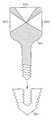
- FIG. 1Ais a schematic diagram illustrating generally one example of an imagable fiducial marker that includes a built-in conical divot or other male or female receptacle, or the like.
- FIG. 1Bis a schematic diagram illustrating generally one example of an imagable fiducial marker that omits the divot illustrated in FIG. 1A , but which is both locatable by a remote positioning system and imagable by one or more imaging modalities.
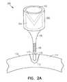
- FIG. 2Ais a schematic diagram illustrating generally an alternative example of a fiducial marker that includes a cylindrical imaging fiducial locator and a conical or other divot or other receptacle for receiving a positioning wand tip or the like.
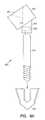
- FIG. 2Bis a schematic diagram illustrating generally one example of an imagable fiducial marker that omits the divot illustrated in FIG. 2A , but which is both locatable by a remote positioning system and imagable by one or more imaging modalities.
- FIG. 3Ais a schematic diagram illustrating generally one example of a positioning wand for use in conjunction with a remotely-located camera or other like device of an optical positioning system, such as can be coupled to an image-guided surgical workstation in an operating room.
- FIG. 3Bis a schematic diagram, similar in certain respects to FIG. 3A , illustrating generally one example of a positioning wand including energy reflective surfaces that are capable of being oriented or aimed toward a remote detector.
- FIG. 3Cis a perspective view schematic diagram illustrating generally, by way of example, but not by way of limitation, certain generally “cylindrical” columnar structures having faceted lateral peripheral surfaces.
- FIG. 3Dis a schematic diagram illustrating generally an example of a positioning wand with flat disk-shaped pieces of reflective tape are attached in a known configuration.
- FIG. 4is a schematic diagram illustrating generally, by way of example, but not by way of limitation, an image guided surgical (IGS) computer workstation to which an optical positioning system is coupled.
- IGSimage guided surgical
- FIG. 5is a schematic diagram illustrating generally a unitary divot assembly that includes multiple divots.
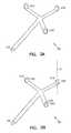
- FIG. 6Ais a schematic diagram illustrating generally a divot assembly that includes a swiveling tilted head carrying a conical or other divot or the like.
- FIG. 6Bis a schematic diagram illustrating generally a locator assembly that includes a swiveling tilted head including a surface that reflects electromagnetic energy.
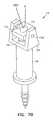
- FIG. 7Ais a schematic diagram illustrating generally a divot assembly that includes a swiveling and pivotable head carrying a conical or other divot.
- FIG. 7Bis a schematic diagram illustrating generally a divot assembly that includes a swiveling and pivotable head including a surface that reflects electromagnetic energy.
- FIG. 8is a schematic diagram illustrating conceptually a fiducial marker carrier that is attachable to (and also detachable from) a single location on the patient's skull, thereby reducing trauma to the patient.
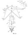
- FIG. 9is an exploded view schematic diagram illustrating generally one example of the carrier, including a frame, a post, and a base.
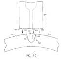
- FIG. 10is a schematic diagram illustrating a portion of a fiducial marker carrier that includes at least one antirotational spike for engaging the surface of the skull.
- assemblyis not intended to be limited to a structure that is assembled from multiple components, but also includes unitary or integrally-formed structures or the like.
- FIG. 1Ais a schematic diagram illustrating generally, by way of example, but not by way of limitation, one example of an imagable fiducial marker 100 that includes a built-in divot 102 .
- the divot 102includes a female receptacle, such as the illustrated conical depression.
- a divotalso refers to any other male or female receptacle, or the like.
- the divot 102is capable of receiving a correspondingly sized and shaped mating tip of a positioning wand or like instrument.
- a wand or instrumentis useful for registering the actual physical location of the patient's skull to preoperative or other images of the subject's brain.
- Such imagesare typically stored in a memory of an image-guided surgical (IGS) computer workstation.
- IGSimage-guided surgical
- the fiducial marker 100includes an imagable substantially spherical fiducial locator 104 .
- the fiducial 104is locatable using one or more imaging system modalities.
- a shaft 106extends orthogonally outward from a circumferential portion of the spherical fiducial 104 .
- the shaft 106includes an externally threaded portion 108 .
- the externally threaded portion 108is sized and shaped for being received within a correspondingly sized and shaped mating internally threaded receptacle 110 of an externally-threaded self-tapping base 112 .
- the base 112is capable of being mounted in a skull 114 , such as either flush to (or even recessed from) an outer surface 116 of the skull 114 .
- a suitable base 112is described in commonly-assigned Mazzocchi et al. U.S. patent application Ser. No. 10/206,884 entitled FIDUCIAL MARKER DEVICES, TOOLS, AND METHODS, which was filed on Jul. 24, 2002, and which is incorporated herein by reference in its entirety, including its disclosure relating to a flush or recessed mounted base and other fiducial marker devices, tools and methods.
- the base 112need not be configured for mounting flush to or recessed from the outer surface 116 of the skull 114 .
- the shaft 106includes a pointed tip 115 .
- the receptacle 110 of the base 112is shaped to accommodate the pointed tip 115 .
- the tip 115need not be pointed.
- the imaging spherical fiducial locator 104houses a generally spherical (e.g., except for the conic cutaway of the divot 102 ) sealed interior cavity 118 .
- the cavity 118is filled with an imagable fluid that is visible on one or more imaging modalities (e.g., MR, CT, etc.).
- the apex of the conic divot 102is located at a center of mass of the imaging spherical fiducial locator 104 .
- the fiducial marker 100 illustrated in FIG. 1Adoes not require any such exchange of the imaging fiducial for a separate divot. Instead, the divot is integrated into the imaging fiducial itself, as illustrated in FIG. 1A . This reduces the complexity of the image-guided surgical procedure and, therefore, reduces its cost.
- the base 112is constructed of stainless steel.
- the shaft 106 and the imaging spherical fiducial locator 104are constructed of molded plastic polymer.
- the imaging spherical fiducial locator 104includes an open cavity 118 for receiving the imaging fluid, and for then receiving an insertable plastic conical divot 102 that adhesively or otherwise seals the cavity 118 to retain the imaging fluid therein.
- the imaging fluid in the cavity 118is visible and provides good contrast on images produced by at least one imaging modality.
- the imaging fluidis multimodal (i.e., locatable by more than one imaging modality), such as by using a mixture of different imaging fluids that are locatable on different imaging modalities.
- the plastic forming the imaging spherical fiducial locator 104includes a substance that is viewable on a first imaging modality, while the imaging fluid within the cavity 118 is viewable on a different second imaging modality.
- the plastic imaging fiducial locator 104is doped with a substance having a high atomic number (Z), such as barium, titanium, iodine, silver, gold, platinum, iodine, stainless steel, titanium dioxide, etc. that provide good contrast on a CT or other radiographic imaging system.
- Zhigh atomic number
- the fluid within the cavity 118includes gadopentatate dimeglumine, gadoteridol, ferric chloride, copper sulfate, or any other suitable MRI contrast agent, such as described in chapter 14 of Magnetic Resonance Imaging, 2 nd ed., edited by Stark and Bradley, 1992, which is incorporated herein by reference.
- the cavity 118is omitted.
- the spherical fiducial locator 104is constructed of a substantially solid plastic or other material that is hygroscopic, that is, capable of receiving and retaining a fluid, such as an imaging fluid that is viewable on an imaging system (e.g., an MRI imaging system or the like).
- the plastic forming the spherical fiducial locator 104is doped or otherwise includes a substance that is viewable on a different imaging system, such as, for example, a CT or other radiographic imaging system.
- solid plasticsthat can be made hygroscopic include, among other things, nylon and polyurethane.
- Using a hygroscopic materialavoids the complexity and cost associated with manufacturing a sealed cavity 118 for retaining an imaging fluid. Moreover, by adapting the solid hygroscopic plastic for imaging using a first modality, and by using the imaging fluid for imaging using a second modality, each of the solid and the fluid can be separately tailored toward providing better contrast for its particular imaging modality.
- the fiducial locator 104includes a rigid solid (e.g., substantially spherical, but for the conic divot) interior.
- This solid materialis doped with a substance that provides good contrast using a first imaging modality (e.g., CT).
- a hygroscopic outer coatingis formed thereupon. The coating permits soaking up a fluid that provides a good contrast using a second imaging modality (e.g., MRI).
- the outer surface of the imaging spherical fiducial locator 104is reflective of light or other electromagnetic energy. Consequently, it is also locatable by the operating room camera in an optical positioning system that is coupled to the image-guided workstation (e.g., during patient registration).
- the outer surface of the imaging spherical fiducial locator 104includes light-reflective micro-spheres (e.g., embedded in an adhesive covering the imaging spherical fiducial 104 ).
- the outer surface of the imaging spherical fiducial 104is covered with an adhesive-backed light-reflective tape, such as SCOTCHLITE® 9810 Reflective Material Multipurpose Tape sold by Minnesota Mining and Manufacturing Co. (“3M®”), of Saint Paul, Minn.
- an adhesive-backed light-reflective tapesuch as SCOTCHLITE® 9810 Reflective Material Multipurpose Tape sold by Minnesota Mining and Manufacturing Co. (“3M®”), of Saint Paul, Minn.
- FIG. 2Ais a schematic diagram illustrating generally, by way of example, but not by way of limitation, an alternative example of a fiducial marker 200 that includes a generally cylindrical imaging fiducial locator 202 and a conical or other divot 102 .
- the generally cylindrical imaging fiducial locator 202includes a sealed cavity 204 for receiving and retaining an imagable fluid, as discussed above.
- the sealed cavity 204is omitted, as discussed above.
- the generally cylindrical imaging fiducial locator 202is instead constructed of a substantially solid hygroscopic plastic that carries an imagable fluid (as discussed above), such as for providing multimodal contrast across different imaging modalities.
- the generally cylindrical outer surface of the imaging fiducial locator 202is reflective, as discussed above, such that the imaging fiducial locator 202 is also visible to a camera of an optical position locating system that is coupled to an image-guided surgical workstation (e.g., during patient registration and/or a subsequent image-guided surgical procedure).
- the imaging fiducial locator 202is covered with adhesive-backed reflective tape taken from a rectangular strip of such tape that is wound into a roll.
- the generally cylindrical shape of the outer surface of the imaging fiducial locator 202is much easier to wrap using a wound rectangular strip of the adhesive reflective tape than a spherical surface, such as is illustrated in FIG. 1A , and therefore costs less to manufacture.
- the term “generally cylindrical”is not limited to a perfectly cylindrical surface, but instead is understood to include any faceted or other column or like structure (e.g., an octogonal cylinder a hexagonal cylinder, etc.) that includes a lateral peripheral surface that easily accommodates receiving a wound rectangular or similar strip of tape (as opposed to a spherical, elliptical, or conical surface, to which is more difficult to evenly apply a wound rectangular strip of tape taken from a roll). Examples of such generally “cylindrical” columnar structures having faceted lateral peripheral surfaces are illustrated in FIG. 3C .
- the divot 102is omitted from the fiducial marker 100 or 200 .
- the resulting fiducial markeris still configured to be locatable by a remote positioning system as well as imagable using one or more imaging modalities.
- the outer surface 104 or 202is still configured to be light reflective, such as discussed above.
- the fiducial markers 100 and 200still advantageously are locatable using one or more imaging modalities (e.g., MR, CT, or other imaging system providing 3D or other internal images within a subject) as well as also being locatable external to the subject, such as by using a remote camera or like component of an optical or other positioning system, e.g., that is coupled to an image-guided workstation.
- imaging modalitiese.g., MR, CT, or other imaging system providing 3D or other internal images within a subject
- a remote camera or like component of an optical or other positioning systeme.g., that is coupled to an image-guided workstation.
- thispermits automatic registration of the actual location of the subject in the operating room (e.g., using the cameras to locate the light reflective fiducial markers 100 or 200 ) to preoperative images of the patient on which the same imagable fiducial markers 100 and 200 appear.
- the divots 102are not needed and can be omitted, as illustrated by the divotless spherical imagable reflective fiducial marker 120 in FIG. 1B and the divotless cylindrical imagable reflective fiducial marker 206 in FIG. 2B .
- the cavity 204is omitted, and the fiducial marker 206 includes a solid structure that is doped or otherwise configured (e.g., hygroscopic) for providing good imaging contrast using one (e.g., CT) or more imaging modalities.
- a solid structurethat is doped or otherwise configured (e.g., hygroscopic) for providing good imaging contrast using one (e.g., CT) or more imaging modalities.
- the fiducial markers 100 and 200 respectively illustrated in FIGS. 1A and 2Ainclude the illustrated divots 102 and are locatable by a remote positioning system (such as by including light-reflective outer surfaces and/or embedded coils that perform magnetic field sensing in a magnetic field based positioning system).
- the fiducial markers 100 and 200need not be configured for providing contrast on the one or more imaging modalities.
- the preoperative imagesare taken with imagable fiducial markers placed within respective bases 112 .
- Such imagable fiducial markersare then replaced (within their respective bases 112 ) by nonimagable fiducial markers that are locatable by a remote positioning system, such as by including both a divot and a light-reflective surface.
- a remote positioning systemsuch as by including both a divot and a light-reflective surface.
- the light reflective surfacepermits automatic location by the remote positioning system.
- a wand or other locating instrumentcan be placed within the divot to perform the remote locating of the fiducial marker.
- FIGS. 1A and 2Aillustrate examples in which a shaft 106 is received within a base 112 that is mounted flush to (or recessed from) the outer surface 116 of the skull 114 , this is not required.
- the shaft 106is manufactured as a stainless steel or other suitable material that is capable of acting as a self-tapping bone screw.
- the threaded portion 108 of the shaft 106is threaded directly into the skull 114 without using any base 112 .
- the base 112includes a shaft or flange portion that rises above the outer surface 116 of the skull 114 .
- the fiducial markers 100 and 200may use a threaded or other shaft 106 for coupling to the base 112 , or alternatively may use a snap-fit clip or a like attachment device for coupling to the base 112 .
- FIG. 3Ais a schematic diagram illustrating generally, by way of example, but not by way of limitation, one example of a positioning wand 300 , such as for use with a remotely-located camera or other like device of an optical positioning system configured for being coupled to an image-guided surgical workstation in an operating room.
- the wand 300includes a tip 302 that is sized and shaped to permit being received in a divot 102 of a skull-mounted fiducial marker (such as fiducial markers 100 and 200 ).
- the wand 300includes a plurality of cylindrically-shaped fiducial locators 304 that are locatable by the camera or other like device of the optical positioning system.
- the fiducial locators 304(which typically need not include divots) on the wand 300 are positioned in a known spatial relationship to each other and to the tip 302 of the wand 300 .
- the optical positioning systemis capable of computing the location of the wand tip 302 , which is in a known spatial relationship with the configuration of fiducial locators 304 . This permits the wand 300 to be used in conjunction with the optical positioning system to register the patient and to further plan and/or perform the surgical procedure using the image-guided surgical workstation.
- the fiducial locators 304are covered with adhesive-backed reflective tape, as discussed above.
- the cylindrical (or faceted cylindrical) shape of the fiducial locators 304permits easier wrapping by the reflective tape than the spherical fiducials, as discussed above. This reduces the cost of manufacturing the fiducial locators 304 and, in turn, reduces the cost of manufacturing the positioning wand 300 .
- FIG. 3Bis a schematic diagram, similar in certain respects to FIG. 3A , but illustrating a wand 306 that includes locators 308 A-C having swiveling or fixed cylindrical locators 308 A-C having respective slanted (e.g., flat, parabolic, or other) top surfaces 310 A-C (e.g., non-orthogonal with respect to a longitudinal center axis 311 of the locator 308 ) that reflect light or other electromagnetic energy for being located by a remote detector.
- each such locator 308includes a shaft inserted into a hole or other receptacle in the wand 306 .
- the locator 308to rotate with respect to its mounting location on the wand 306 .
- Either the wand 306 itself or the individual locators 308 A-Care oriented by the user to aim the reflective surfaces 310 A-C toward a camera or other detector of an optical positioning system.
- the circumferential surfaces of the cylindrical locators 308 A-Care also light-reflective, however, this is not required.
- the reflective tape disksare adhered to the flat slanted top surfaces 310 A-C and the circumferential lateral surfaces of the cylindrical locators 308 A-C are not reflective.
- FIG. 3Cis a perspective view schematic diagram illustrating generally, by way of example, but not by way of limitation, certain generally “cylindrical” columnar structures 312 , 314 , and 316 having faceted lateral peripheral surfaces. Such surfaces are conducive to receiving a rectangular or like strip of adhesive reflective tape. Such structures, therefore, are particularly well-suited for implementing locators that are remotely locatable by an optical positioning system. Such remotely detectable locators are suitable for use in the fiducial markers illustrated in FIGS. 2A and 2B , as well as for use in the remotely detectable locators of the positioning wands illustrated in FIGS. 3A and 3B .
- Such remotely detectable locatorsare also useful for being affixed in a known relationship to the patient, such as to the operating table or to a skull-immobilizing headframe. This provides a remotely detectable absolute positional reference to an optical positioning system. Such remotely detectable locators are also useful for being affixed to a biopsy needle, shunt catheter, or other instrument being introduced through a trajectory guide device or otherwise used in an image-guided surgical procedure.
- FIG. 3Dis a schematic diagram illustrating generally, by way of example, but not by way of limitation, an alternative example of a positioning wand 318 .
- a positioning wand 318which flat disk-shaped pieces of reflective tape are attached to the wand 318 in a known configuration, such as at the distal ends of radial arms extending therefrom.
- FIG. 4is a schematic diagram illustrating generally, by way of example, but not by way of limitation, an image guided surgical (IGS) computer workstation 400 , which is capable of displaying previously acquired and loaded preoperative images of a patient's skull. On these preoperative images appear viewable images of imagable fiducial markers that were screwed into the patient's skull before the preoperative imaging (e.g., using MRI, CT, etc.). In the example illustrated in FIG. 4 , the imagable fiducial locators have been unscrewed from respective bases 402 screwed into the patient's skull.
- IGSimage guided surgical
- the imagable fiducial locatorshave been replaced by patient registration divot assemblies 404 that have been screwed into (or otherwise coupled to) respective bases 402 in the patient's skull 114 .
- the registration divot assemblies 404are configured to receive a shaft tip 406 of a positioning wand 408 that is locatable by one or more remote cameras 410 A-B (or other sensing devices) of an optical position detection system 412 connected to the IGS workstation 400 .
- the positioning wand 408includes spherical reflective fiducial locators 414 .
- the fiducial locators 414are arranged in a known spatial relationship to each other (however, it may alternatively use other reflective locators such as discussed elsewhere in this document).
- the optical positioning system 412includes an infrared light (or other energy source) 416 that provides light that is reflected from the reflective fiducial locators 414 . This permits the reflective fiducial locators 414 on the positioning wand 408 to be located and recognized by the cameras 410 A-B. In some circumstances, however, the field of view (or “sweet spot” of the field of view) provided by cameras 410 A-B is limited. This sometimes makes it difficult for the optical positioning system 412 to recognize the positioning wand 408 .
- the recessed receptacle in the divot assembly 404typically limits the range within which the probe 408 can be manipulated (e.g., to bring it within the field of view) while retaining the wand tip 406 within the recessed receptacle.
- FIG. 5is a schematic diagram illustrating generally, by way of example, but not by way of limitation, a unitary divot assembly 500 that includes multiple divots 502 .
- the unitary divot assembly 500is configured such that it can be threaded into or otherwise coupled to a base 504 that is secured to the patient's anatomy (wherein the base 504 is also configured for alternatively receiving an imagable fiducial locator, e.g., during preoperative imaging).
- FIG. 5illustrates multiple conical receptacle divots 502 having commonly located apexes.
- the divotsinclude a top conical divot 502 A and four side conical divots 502 B-F.
- the four side conical divots 502 B-Fare distributed around the cylindrical lateral peripheral circumference of the upper portion of the divot assembly 500 .
- the wand tip 406may be inserted into any one of the divots 502 . This permits a greater range of motion of the positioning wand 408 . As a result, it is easier to bring the reflective fiducials 414 on the positioning wand 408 into the field of view of the cameras 410 A-B of the optical positioning system 412 .
- FIG. 6Ais a schematic diagram illustrating generally, by way of example, but not by way of limitation, a divot assembly 600 that includes a swiveling tilted head 602 carrying a conical or other divot 604 or the like.
- the head 602is tilted with respect to a cylindrical coupling 606 extending outwardly therefrom.
- the coupling 606includes a hollow interior or other (female or male) connector that snap-fits onto and rotatably rides upon a mating (male or female) connector 608 that is located at a proximal end of a shaft 610 portion of the divot assembly 600 .
- the swiveling apex 612 of the divot 604is designed to coincide with the center of mass of the imagable fiducial locator for which the divot assembly 600 has been substituted during patient registration.
- the swiveling tilted head 602permits a wide range of motion of the positioning wand 408 when the wand tip 406 is inserted into the divot 604 . As a result of such rotational articulation, it is easier to bring the reflective fiducial locators 414 on the positioning wand 408 into the limited field of view of the cameras 410 A-B of the optical positioning system 412 .
- FIG. 7Ais a schematic diagram illustrating generally, by way of example, but not by way of limitation, a divot assembly 700 that includes a swiveling and pivotable head 702 carrying a conical or other divot 704 .
- the head 702is carried by a shackle-like U-shaped bracket 704 that rotatably rides upon a snap-fit or other capturing post 706 that extends upward from a shaft portion 708 of the divot assembly 700 . This allows swiveling of the bracket 704 (and the head 702 carried by the bracket 702 ) with respect to the shaft 708 .
- the head 702is suspended between upward-projecting risers of the bracket 704 by axels 710 A-B extending outward from opposing sides of the head 702 and received within corresponding receptacles in the risers of the bracket 704 .
- Thispermits pivoting/tilting articulation of the head 702 with respect to the swiveling bracket 704 . Therefore, this example provides a swiveling and adjustably tiltable divot 704 that is designed such that its apex 712 coincides with the center of mass of the imagable fiducial locator for which the divot assembly 700 has been substituted during patient registration.
- the swiveling tiltable head 702advantageously permits a greater range of motion of the positioning wand 408 when the wand tip 406 is inserted into the divot 704 . As a result, it is easier to bring the reflective fiducials 414 on the positioning wand 408 into the limited field of view of the cameras 410 A-B of the optical positioning system 412 .
- FIGS. 6B and 7Bare schematic diagrams that are similar in certain respects to FIGS. 6A and 7A .
- the locator assemblies 614 and 714 illustrated by respective FIGS. 6B and 7Bomit the respective divots 604 and 704 .
- the locator assemblies 614 and 714provide aimable electromagnetic energy (e.g., light) reflective surfaces 616 and 716 , respectively.
- the reflective surfaces 616 and 716are aimed at the camera of an optical positioning system 412 to allow automatic detection of the locator assemblies 614 and 714 without requiring the use of a positioning wand 408 .
- the reflective surfaces 616 and 716are configured so that, when aimed properly, they produce a reflected image that can be correlated to a previously acquired patient image on which an image of an imagable fiducial marker appears.
- reflective surface 616corresponds to the center of mass of a similarly sized spherical locator on an imagable fiducial marker assembly for which locator assembly 614 is substituted during patient registration.
- reflective surface 716includes a circular disk-shaped piece of reflective tape affixed to a surface 718 such that this reflective disk pivots about the axis provided by axels 710 A-B. In this manner, the reflected disk shape corresponds to the center of mass of a similarly sized spherical locator on an imagable fiducial marker assembly for which locator assembly 714 is substituted during patient registration.
- FIG. 8is a schematic diagram illustrating conceptually, by way of example, but not by way of limitation, a fiducial marker carrier 800 that is attachable to (and also detachable from) a single location on the patient's skull 114 , thereby reducing trauma and risk of infection to the patient.
- the fiducial marker carrier 800is configured for carrying multiple different imagable fiducial locators 802 such that they are positioned at different locations about the patient's skull 114 .
- the carrier 800uses a keyed mounting arrangement, such that the carrier 800 can be attached to the patient's skull 114 , then detached from the patient's skull 114 , and later reattached to the patient's skull 114 in the same orientation in which it was initially attached to the patient's skull 114 .
- the carrier 800includes a keyed frame 804 that is attached to a keyed post 806 for mounting.
- the keyed post 806is, in turn, attached to a single flush-mounted or recessed-mounted or other keyed base 808 , which was previously screwed into the patient's skull 114 .
- This keyed arrangement of the frame 804 , the post 806 , and the base 808permits attachment, detachment, and reattachment in the same orientation as the original attachment, as discussed above.
- the post 806is integrally formed as part of the frame 804 , rather than being keyed for attachment thereto.
- the imagable locators 802are placed about the subject's head such that they surround the patient's skull. Although such a surrounding arrangement is not required, it is believed to improve the accuracy of using the images of the locators 802 (e.g., in conjunction with the IGS workstation) for planning and/or performing an image-guided surgical procedure, as compared to an arrangements in which locators are disposed more closely together (e.g., on the same side of the subject's head).
- FIG. 9is an exploded view schematic diagram illustrating generally, by way of example, but not by way of limitation, one example of the carrier 800 , including the frame 804 , the post 806 , and the base 808 .
- the base 808includes self-tapping external threads 902 , and is capable of being mounted flush with (or even recessed within) the patient's skull 114 .
- the base 808includes an internally-threaded receptacle 904 that is sized and otherwise configured such that it is capable of receiving a screw.
- the base 808also includes a female or male keying feature for receiving a mating keying feature of the post 806 to fixedly define the orientation of the post 806 with respect to the base 808 .
- the keying featureincludes a key slot 906 extending radially outward from the receptacle 904 along a proximal surface of the base 808 .
- the post 806includes a proximal end 908 and a distal end 910 .
- the post 806includes a center lumen 912 in which an attachment screw 914 is received and seated.
- the screw 914attaches the post 806 to the base 808 .
- the distal end 910 of the post 806includes a male or female keying feature (such as a key protrusion 916 extending radially outward from the center lumen 912 along the distal end 910 of the post 806 ) that mates with the keying feature (e.g., key slot 906 ) of the base 808 .
- keying featuree.g., key slot 906
- the center lumen 912includes a keyed seating receptacle 918 (or an analogous male keyed feature) for receiving a mating keyed feature of the frame 804 .
- the keyed seating receptacle 918includes an increased diameter of the center lumen 912 (with respect to more distal portions of the center lumen 912 ) to provide the seating, and a radially-outwardly extending slot 920 to provide the keying.
- the frame 804includes legs 922 A-D (or a fewer or greater number of legs 922 ), such as extending radially outwardly from a hub 924 and downwardly toward the middle portion of the patient's skull.
- Each of the legs 922includes, such as at its respective distal end, a threaded receptacle 924 A-D (or a snap-fitting or any other coupling) for receiving at least one of an imagable fiducial marker assembly 926 , a divot assembly 928 , a locator assembly 930 (e.g., reflector, LED, microcoil, etc.) that is remotely detectable by a positioning system in an operating room, or a combination 932 of two or more of the above.
- a threaded receptacle 924 A-Dor a snap-fitting or any other coupling
- an imagable fiducial marker assembly 926for receiving at least one of an imagable fiducial marker assembly 926 , a divot assembly 928 , a locator assembly 930 (e.g., reflector, LED, microcoil, etc.) that is remotely detectable by a positioning system in an operating room, or a combination 932 of two or
- a combination 932includes an imagable locator and at least one of an operating room position locator and a divot
- instantiations of such a combination 932may be permanently affixed to corresponding locations on the legs 922 of the frame 804 .
- the hub 924 portion of the frame 804also includes a downwardly protruding key 934 (or analogous female receptacle) that mates to the keyed seating receptacle 918 , of the post 806 , into which the key 934 is received.
- a screw 936is inserted through the hub 924 , the key 934 , and into an engaging interior threaded portion of the center lumen 912 . This securely attaches the frame 904 to the post 806 in the fixedly defined orientation.
- the example illustrated in FIG. 9also includes at least one optional instrument mount 938 .
- a reference divot(e.g., providing a position reference) is attached to the instrument mount 938 .
- FIGS. 8 and 9illustrate examples in which a fiducial marker carrier 800 is mounted using a single base 808
- the carriermay be mounted using two or more bases 808 at the same location on the patient's skull (that is, at adjacent locations within the same scalp incision, or like limited trauma/infection risk zone; the incision need only be large enough to accommodate the two or more bases 808 ).
- Using two or more side-by-side bases 808 to attach the post 806avoids potential rotational misalignment of a single base 808 coming slightly unscrewed from its original position.
- the distal end 910 of the post 806is keyed both to the base 808 and, using the antirotation spike(s) 1000 , to indentation(s) made in the surface 116 of the skull 114 .
- the post 806 and the base 808need not be keyed to each other. Instead, in such an example, the post 806 is keyed only to indentation(s) made by the antirotation spike(s) 1000 in the surface 116 of the skull 114 .
- the various above-described locators(e.g., on the subject's skull, or on a wand, as illustrated in FIG. 3 ) alternatively or additionally include an electromagnetic (EM) coil that permits determination of the position of the locator using an EM coil detecting positioning system coupled to an IGS workstation rather than the optical positioning system 412 discussed above.
- EMelectromagnetic
Landscapes
- Health & Medical Sciences (AREA)
- Surgery (AREA)
- Life Sciences & Earth Sciences (AREA)
- Engineering & Computer Science (AREA)
- Animal Behavior & Ethology (AREA)
- Veterinary Medicine (AREA)
- Biomedical Technology (AREA)
- Heart & Thoracic Surgery (AREA)
- Medical Informatics (AREA)
- Molecular Biology (AREA)
- Nuclear Medicine, Radiotherapy & Molecular Imaging (AREA)
- General Health & Medical Sciences (AREA)
- Public Health (AREA)
- Robotics (AREA)
- Oral & Maxillofacial Surgery (AREA)
- Pathology (AREA)
- Magnetic Resonance Imaging Apparatus (AREA)
- Apparatus For Radiation Diagnosis (AREA)
- Holo Graphy (AREA)
- Acyclic And Carbocyclic Compounds In Medicinal Compositions (AREA)
- Manufacturing Optical Record Carriers (AREA)
Abstract
Description
Claims (18)
Priority Applications (1)
| Application Number | Priority Date | Filing Date | Title |
|---|---|---|---|
| US12/749,312US8073530B2 (en) | 2003-02-25 | 2010-03-29 | Fiducial marker devices, tools, and methods |
Applications Claiming Priority (2)
| Application Number | Priority Date | Filing Date | Title |
|---|---|---|---|
| US10/374,677US7720522B2 (en) | 2003-02-25 | 2003-02-25 | Fiducial marker devices, tools, and methods |
| US12/749,312US8073530B2 (en) | 2003-02-25 | 2010-03-29 | Fiducial marker devices, tools, and methods |
Related Parent Applications (1)
| Application Number | Title | Priority Date | Filing Date |
|---|---|---|---|
| US10/374,677DivisionUS7720522B2 (en) | 2002-07-29 | 2003-02-25 | Fiducial marker devices, tools, and methods |
Publications (2)
| Publication Number | Publication Date |
|---|---|
| US20100217120A1 US20100217120A1 (en) | 2010-08-26 |
| US8073530B2true US8073530B2 (en) | 2011-12-06 |
Family
ID=32868922
Family Applications (5)
| Application Number | Title | Priority Date | Filing Date |
|---|---|---|---|
| US10/374,677Active2028-06-11US7720522B2 (en) | 2002-07-29 | 2003-02-25 | Fiducial marker devices, tools, and methods |
| US10/688,801Active2025-12-30US7643867B2 (en) | 2003-02-25 | 2003-10-17 | Fiducial marker devices, tools, and methods |
| US11/689,356Active2026-05-02US8185184B2 (en) | 2003-02-25 | 2007-03-21 | Fiducial marker devices, tools, and methods |
| US12/619,512Expired - Fee RelatedUS8032204B2 (en) | 2003-02-25 | 2009-11-16 | Fiducial marker devices, tools, and methods |
| US12/749,312Expired - Fee RelatedUS8073530B2 (en) | 2003-02-25 | 2010-03-29 | Fiducial marker devices, tools, and methods |
Family Applications Before (4)
| Application Number | Title | Priority Date | Filing Date |
|---|---|---|---|
| US10/374,677Active2028-06-11US7720522B2 (en) | 2002-07-29 | 2003-02-25 | Fiducial marker devices, tools, and methods |
| US10/688,801Active2025-12-30US7643867B2 (en) | 2003-02-25 | 2003-10-17 | Fiducial marker devices, tools, and methods |
| US11/689,356Active2026-05-02US8185184B2 (en) | 2003-02-25 | 2007-03-21 | Fiducial marker devices, tools, and methods |
| US12/619,512Expired - Fee RelatedUS8032204B2 (en) | 2003-02-25 | 2009-11-16 | Fiducial marker devices, tools, and methods |
Country Status (3)
| Country | Link |
|---|---|
| US (5) | US7720522B2 (en) |
| AT (1) | ATE506024T1 (en) |
| DE (1) | DE602004032316D1 (en) |
Cited By (8)
| Publication number | Priority date | Publication date | Assignee | Title |
|---|---|---|---|---|
| WO2014201108A1 (en)* | 2013-06-11 | 2014-12-18 | Adventist Health System/Sunbelt, Inc. | Probe for surgical navigation |
| US9498290B2 (en) | 2012-07-19 | 2016-11-22 | MRI Interventions, Inc. | Surgical navigation devices and methods |
| WO2017017496A1 (en)* | 2015-07-24 | 2017-02-02 | Izi Medical Products, Llc | Dynamic reference frame for surgical navigation system |
| USD824027S1 (en) | 2016-01-13 | 2018-07-24 | MRI Interventions, Inc. | Fins for a support column for a surgical trajectory frame |
| USD829904S1 (en) | 2016-01-13 | 2018-10-02 | MRI Interventions, Inc. | Curved bracket for surgical navigation systems |
| US10376333B2 (en) | 2016-01-14 | 2019-08-13 | MRI Interventions, Inc. | Devices for surgical navigation systems |
| US11980426B2 (en) | 2020-08-03 | 2024-05-14 | Warsaw Orthopedic, Inc. | System and method for preliminary registration |
| US12369988B2 (en) | 2021-01-06 | 2025-07-29 | Mako Surgical Corp. | Tracker for a navigation system |
Families Citing this family (162)
| Publication number | Priority date | Publication date | Assignee | Title |
|---|---|---|---|---|
| JP2005516724A (en)* | 2002-02-11 | 2005-06-09 | スミス アンド ネフュー インコーポレーテッド | Image guided fracture reduction |
| US7720522B2 (en) | 2003-02-25 | 2010-05-18 | Medtronic, Inc. | Fiducial marker devices, tools, and methods |
| US7787934B2 (en) | 2002-07-29 | 2010-08-31 | Medtronic, Inc. | Fiducial marker devices, tools, and methods |
| US20040030237A1 (en)* | 2002-07-29 | 2004-02-12 | Lee David M. | Fiducial marker devices and methods |
| US20040019265A1 (en)* | 2002-07-29 | 2004-01-29 | Mazzocchi Rudy A. | Fiducial marker devices, tools, and methods |
| USD528211S1 (en) | 2003-02-25 | 2006-09-12 | Image-Guided Neurologics, Inc. | Fiducial marker |
| FR2854318B1 (en)* | 2003-05-02 | 2010-10-22 | Perception Raisonnement Action | DETERMINING THE POSITION OF AN ANATOMIC ELEMENT |
| US8150495B2 (en) | 2003-08-11 | 2012-04-03 | Veran Medical Technologies, Inc. | Bodily sealants and methods and apparatus for image-guided delivery of same |
| US7398116B2 (en) | 2003-08-11 | 2008-07-08 | Veran Medical Technologies, Inc. | Methods, apparatuses, and systems useful in conducting image guided interventions |
| US7862570B2 (en) | 2003-10-03 | 2011-01-04 | Smith & Nephew, Inc. | Surgical positioners |
| US7764985B2 (en) | 2003-10-20 | 2010-07-27 | Smith & Nephew, Inc. | Surgical navigation system component fault interfaces and related processes |
| ATE495706T1 (en)* | 2003-11-14 | 2011-02-15 | Smith & Nephew Inc | ADJUSTABLE SURGICAL CUTTING SYSTEMS |
| WO2005072629A1 (en)* | 2004-01-16 | 2005-08-11 | Smith & Nephew, Inc. | Computer-assisted ligament balancing in total knee arthroplasty |
| CA2561493A1 (en) | 2004-03-31 | 2005-10-20 | Smith & Nephew, Inc. | Methods and apparatuses for providing a reference array input device |
| EP1737375B1 (en) | 2004-04-21 | 2021-08-11 | Smith & Nephew, Inc | Computer-aided navigation systems for shoulder arthroplasty |
| US7925326B2 (en)* | 2004-09-03 | 2011-04-12 | Siemens Molecular Imaging, Inc. | Solid fiduciary marker for multimodality imaging |
| WO2006091704A1 (en) | 2005-02-22 | 2006-08-31 | Smith & Nephew, Inc. | In-line milling system |
| US20070066881A1 (en) | 2005-09-13 | 2007-03-22 | Edwards Jerome R | Apparatus and method for image guided accuracy verification |
| EP1924198B1 (en)* | 2005-09-13 | 2019-04-03 | Veran Medical Technologies, Inc. | Apparatus for image guided accuracy verification |
| US7835784B2 (en) | 2005-09-21 | 2010-11-16 | Medtronic Navigation, Inc. | Method and apparatus for positioning a reference frame |
| EP1774922B1 (en)* | 2005-10-12 | 2008-06-11 | BrainLAB AG | Marker for a navigation system and method for detecting a marker |
| US20070093709A1 (en)* | 2005-10-26 | 2007-04-26 | Abernathie Dennis L | Surgical navigation markers |
| US9141254B2 (en)* | 2005-11-12 | 2015-09-22 | Orthosensor Inc | Navigation system and user interface for directing a control action |
| US8570274B1 (en) | 2005-11-29 | 2013-10-29 | Navisense | Navigation device providing sensory feedback |
| CA2623616A1 (en) | 2005-11-29 | 2007-06-07 | Surgi-Vision, Inc. | Mri-guided localization and/or lead placement systems, related methods, devices and computer program products |
| US8814810B2 (en)* | 2005-12-01 | 2014-08-26 | Orthosensor Inc. | Orthopedic method and system for mapping an anatomical pivot point |
| US20070237307A1 (en)* | 2006-03-03 | 2007-10-11 | Loubert Suddaby | Radiographic spine marker |
| US20080086051A1 (en)* | 2006-09-20 | 2008-04-10 | Ethicon Endo-Surgery, Inc. | System, storage medium for a computer program, and method for displaying medical images |
| US20080114375A1 (en)* | 2006-11-09 | 2008-05-15 | General Electric Company | Method and apparatus for attaching a dynamic reference |
| ATE446723T1 (en)* | 2006-11-28 | 2009-11-15 | Degudent Gmbh | METHOD FOR PRODUCING A DENTAL RESTORATION |
| US8357165B2 (en)* | 2006-12-22 | 2013-01-22 | Depuy Products, Inc. | Reference array mounting bracket for use with a computer assisted orthopaedic surgery system |
| US20080171930A1 (en)* | 2007-01-16 | 2008-07-17 | Ar2 Partners, Inc. | Method and apparatus for positioning an instrument in a predetermined region within a patient's body |
| US20080319307A1 (en)* | 2007-06-19 | 2008-12-25 | Ethicon Endo-Surgery, Inc. | Method for medical imaging using fluorescent nanoparticles |
| US8457718B2 (en)* | 2007-03-21 | 2013-06-04 | Ethicon Endo-Surgery, Inc. | Recognizing a real world fiducial in a patient image data |
| US8155728B2 (en)* | 2007-08-22 | 2012-04-10 | Ethicon Endo-Surgery, Inc. | Medical system, method, and storage medium concerning a natural orifice transluminal medical procedure |
| US20080221434A1 (en)* | 2007-03-09 | 2008-09-11 | Voegele James W | Displaying an internal image of a body lumen of a patient |
| US20080234544A1 (en)* | 2007-03-20 | 2008-09-25 | Ethicon Endo-Sugery, Inc. | Displaying images interior and exterior to a body lumen of a patient |
| US8081810B2 (en)* | 2007-03-22 | 2011-12-20 | Ethicon Endo-Surgery, Inc. | Recognizing a real world fiducial in image data of a patient |
| US8150494B2 (en)* | 2007-03-29 | 2012-04-03 | Medtronic Navigation, Inc. | Apparatus for registering a physical space to image space |
| WO2009040677A2 (en) | 2007-04-16 | 2009-04-02 | The Governors Of The University Of Calgary | Methods, devices, and systems useful in registration |
| US8175677B2 (en)* | 2007-06-07 | 2012-05-08 | MRI Interventions, Inc. | MRI-guided medical interventional systems and methods |
| WO2009006935A1 (en)* | 2007-07-06 | 2009-01-15 | Karolinska Institutet Innovations Ab | Stereotactic surgery system |
| CA2700523A1 (en)* | 2007-09-24 | 2009-04-02 | Surgivision, Inc. | Mri-guided medical interventional systems and methods |
| US8315689B2 (en)* | 2007-09-24 | 2012-11-20 | MRI Interventions, Inc. | MRI surgical systems for real-time visualizations using MRI image data and predefined data of surgical tools |
| EP2067449A1 (en)* | 2007-12-03 | 2009-06-10 | BrainLAB AG | Attachment system and attachment method for reference adjustments |
| JP5250251B2 (en)* | 2007-12-17 | 2013-07-31 | イマグノーシス株式会社 | Medical imaging marker and its utilization program |
| US9375287B2 (en)* | 2008-01-29 | 2016-06-28 | Covidien Lp | Target identification tool for intra-body localization |
| DE102008022254A1 (en)* | 2008-05-06 | 2009-11-12 | Bernhard Hauri | Marker for a navigation system |
| DE102008045988A1 (en) | 2008-09-05 | 2010-03-11 | Fraunhofer-Gesellschaft zur Förderung der angewandten Forschung e.V. | Identification feature for marking tissue area in e.g. computed tomography, is assigned to tissue area, and attached to surface of tissue area, and comprising selectable code e.g. bar code |
| US20100113912A1 (en)* | 2008-11-03 | 2010-05-06 | Traboulsi Maeghan E | Small diameter mri marker and related method |
| US20110045431A1 (en)* | 2008-11-18 | 2011-02-24 | Groscurth Randall C | Bone screw linking device |
| US20100124731A1 (en)* | 2008-11-18 | 2010-05-20 | Ibur, Llc | Dental device and method for linking physical and digital data for diagnostic, treatment planning, patient education, communication, manufacturing, and data transfer purposes |
| DE102009007291A1 (en)* | 2009-01-27 | 2010-07-29 | Aesculap Ag | Surgical referencing unit, surgical instrument and surgical navigation system |
| US8366719B2 (en) | 2009-03-18 | 2013-02-05 | Integrated Spinal Concepts, Inc. | Image-guided minimal-step placement of screw into bone |
| US8737708B2 (en) | 2009-05-13 | 2014-05-27 | Medtronic Navigation, Inc. | System and method for automatic registration between an image and a subject |
| US8238631B2 (en) | 2009-05-13 | 2012-08-07 | Medtronic Navigation, Inc. | System and method for automatic registration between an image and a subject |
| US8503745B2 (en)* | 2009-05-13 | 2013-08-06 | Medtronic Navigation, Inc. | System and method for automatic registration between an image and a subject |
| US20100292693A1 (en)* | 2009-05-15 | 2010-11-18 | Daniel Nehls | Spinal Marker System and Methods of Use |
| FR2946243A1 (en)* | 2009-06-04 | 2010-12-10 | Inst Curie | DEVICE FOR POSITIONING A PATIENT IN RELATION TO AN EXTERNAL RADIOTHERAPY BEAM |
| US9386942B2 (en) | 2009-06-26 | 2016-07-12 | Cianna Medical, Inc. | Apparatus, systems, and methods for localizing markers or tissue structures within a body |
| EP3106089B1 (en)* | 2009-06-26 | 2020-12-02 | Cianna Medical, Inc. | System for localizing markers or tissue structures within a body |
| US20110098553A1 (en)* | 2009-10-28 | 2011-04-28 | Steven Robbins | Automatic registration of images for image guided surgery |
| KR101810255B1 (en)* | 2010-01-06 | 2017-12-18 | 씨브이코 메디컬 인스트루먼츠 컴퍼니, 인코포레이티드 | Active marker device for use in electromagnetic tracking system |
| DE102010020781B4 (en) | 2010-05-18 | 2019-03-28 | Siemens Healthcare Gmbh | Determination and verification of the coordinate transformation between an X-ray system and a surgical navigation system |
| US8435033B2 (en) | 2010-07-19 | 2013-05-07 | Rainbow Medical Ltd. | Dental navigation techniques |
| EP2595560A1 (en) | 2010-07-23 | 2013-05-29 | Ecole Polytechnique Federale De Lausanne (EPFL) EPFL-TTO | Adjustable fixation system for neurosurgical devices |
| EP3659490B1 (en) | 2010-08-20 | 2025-10-01 | Veran Medical Technologies, Inc. | Apparatus and method for four dimensional soft tissue navigation |
| KR101273386B1 (en)* | 2011-05-04 | 2013-06-11 | 정제교 | Intraoral marker for the synchronization of three dimensional image data |
| US10022171B2 (en) | 2011-07-26 | 2018-07-17 | Scott & White Healthcare | Bone screws and bone screw systems |
| US8798716B1 (en)* | 2011-11-03 | 2014-08-05 | Solstice Corporation | Fiducial markers and related methods |
| CN104105456B (en)* | 2012-02-01 | 2017-07-11 | 皇家飞利浦有限公司 | Multi-modal reference mark and labelling apparatus |
| CN104204615B (en) | 2012-02-15 | 2017-10-24 | 德纳有限公司 | Transmission device and the power train with tilt ball speed changer infinitely variable speed transmission |
| EP2816966B1 (en) | 2012-02-22 | 2023-10-25 | Veran Medical Technologies, Inc. | Steerable surgical catheter comprising a biopsy device at the distal end portion thereof |
| EP2676627B1 (en)* | 2012-04-18 | 2021-07-28 | Medtronic Navigation, Inc. | System and method for automatic registration between an image and a subject |
| US11116576B2 (en) | 2012-06-21 | 2021-09-14 | Globus Medical Inc. | Dynamic reference arrays and methods of use |
| US20210401510A1 (en)* | 2012-06-21 | 2021-12-30 | Globus Medical, Inc. | Dynamic Reference Arrays and Methods of Use |
| US10206693B2 (en) | 2012-07-19 | 2019-02-19 | MRI Interventions, Inc. | MRI-guided medical interventional systems and methods |
| US9192446B2 (en) | 2012-09-05 | 2015-11-24 | MRI Interventions, Inc. | Trajectory guide frame for MRI-guided surgeries |
| EP2893219A4 (en) | 2012-09-06 | 2016-12-28 | Dana Ltd | Transmission having a continuously or infinitely variable variator drive |
| US9599204B2 (en) | 2012-09-07 | 2017-03-21 | Dana Limited | Ball type CVT with output coupled powerpaths |
| WO2014039713A1 (en) | 2012-09-07 | 2014-03-13 | Dana Limited | Ivt based on a ball type cvp including powersplit paths |
| US9689477B2 (en) | 2012-09-07 | 2017-06-27 | Dana Limited | Ball type continuously variable transmission/infinitely variable transmission |
| WO2014039708A1 (en) | 2012-09-07 | 2014-03-13 | Dana Limited | Ball type cvt including a direct drive mode |
| US10030748B2 (en) | 2012-11-17 | 2018-07-24 | Dana Limited | Continuously variable transmission |
| TWI586327B (en)* | 2012-12-27 | 2017-06-11 | Metal Ind Research&Development Centre | Image projection system |
| WO2014124063A1 (en) | 2013-02-08 | 2014-08-14 | Microsoft Corporation | Pervasive service providing device-specific updates |
| US20140303486A1 (en)* | 2013-03-07 | 2014-10-09 | Adventist Health System/Sunbelt, Inc. | Surgical Navigation Planning System and Associated Methods |
| CN105121905A (en) | 2013-03-14 | 2015-12-02 | 德纳有限公司 | Ball type continuously variable transmission |
| WO2014151889A2 (en)* | 2013-03-14 | 2014-09-25 | Dana Limited | Cvt variator ball and method of construction thereof |
| US9551404B2 (en) | 2013-03-14 | 2017-01-24 | Dana Limited | Continuously variable transmission and an infinitely variable transmission variator drive |
| EP3004686B1 (en) | 2013-06-06 | 2018-08-08 | Dana Limited | 3-mode front wheel drive and rear wheel drive continuously variable planetary transmission |
| USD727497S1 (en)* | 2013-07-03 | 2015-04-21 | 7D Surgical Inc. | Support for fiducial markers |
| USD720851S1 (en)* | 2013-07-03 | 2015-01-06 | 7D Surgical Inc. | Handheld support for fiducial markers |
| CN103349568B (en)* | 2013-07-24 | 2015-09-23 | 上海交通大学医学院附属第九人民医院 | A kind of non-invasive navigating surgery positioner |
| WO2015048994A1 (en)* | 2013-10-02 | 2015-04-09 | Mininavident Ag | Navigation system and method for dental and cranio-maxillofacial surgery, positioning tool and method of positioning a marker member |
| US10561465B2 (en)* | 2013-10-09 | 2020-02-18 | Nuvasive, Inc. | Surgical spinal correction |
| WO2015058815A1 (en)* | 2013-10-25 | 2015-04-30 | Brainlab Ag | Magnetic resonance coil unit and method for its manufacture |
| US10540783B2 (en)* | 2013-11-01 | 2020-01-21 | Illumina, Inc. | Image analysis useful for patterned objects |
| US10030751B2 (en) | 2013-11-18 | 2018-07-24 | Dana Limited | Infinite variable transmission with planetary gear set |
| WO2015073948A2 (en) | 2013-11-18 | 2015-05-21 | Dana Limited | Torque peak detection and control mechanism for cvp |
| WO2015090434A1 (en)* | 2013-12-20 | 2015-06-25 | Brainlab Ag | Holder for the attachement of a reference marker device to a body part |
| US10537393B2 (en) | 2014-04-04 | 2020-01-21 | Izi Medical Products, Llc | Medical device for surgical navigation system and corresponding method of manufacturing |
| US20150305612A1 (en) | 2014-04-23 | 2015-10-29 | Mark Hunter | Apparatuses and methods for registering a real-time image feed from an imaging device to a steerable catheter |
| US20150305650A1 (en) | 2014-04-23 | 2015-10-29 | Mark Hunter | Apparatuses and methods for endobronchial navigation to and confirmation of the location of a target tissue and percutaneous interception of the target tissue |
| US10406027B2 (en)* | 2014-06-13 | 2019-09-10 | Novartis Ag | OCT transparent surgical instruments and methods |
| US10709509B2 (en) | 2014-06-17 | 2020-07-14 | Nuvasive, Inc. | Systems and methods for planning, performing, and assessing spinal correction during surgery |
| US20170164958A1 (en)* | 2014-07-29 | 2017-06-15 | David B. Rich | Surgical viewing system |
| USD761428S1 (en)* | 2014-08-14 | 2016-07-12 | Brainlab Ag | Reference marker array |
| EP3193769A4 (en)* | 2014-09-15 | 2018-07-04 | Spinal Developments Pty Ltd | A fiducial marker |
| EP3009097A1 (en)* | 2014-10-17 | 2016-04-20 | Imactis | Method for navigating a surgical instrument |
| TWM503195U (en)* | 2015-01-08 | 2015-06-21 | Reference Technology Ltd Company | Miniature three-dimensional alignment mark |
| US11389268B2 (en)* | 2015-02-05 | 2022-07-19 | Intuitive Surgical Operations, Inc. | System and method for anatomical markers |
| GB2569114B (en)* | 2015-05-08 | 2020-12-16 | Synaptive Medical Barbados Inc | Magnetic resonance visible labels and markers for encoding information |
| US10420626B2 (en) | 2015-06-30 | 2019-09-24 | Canon U.S.A., Inc. | Fiducial markers, systems, and methods of registration |
| CN109938839B (en)* | 2015-08-31 | 2024-03-26 | 北京天智航医疗科技股份有限公司 | Optical tracking tool for navigation surgery |
| WO2017035592A1 (en)* | 2015-09-01 | 2017-03-09 | Cryptych Pty Ltd | Bone screw and instruments for probing position of bone screw |
| USD778441S1 (en) | 2015-09-10 | 2017-02-07 | 7D Surgical Inc. | Fiducial marker support |
| US10030594B2 (en) | 2015-09-18 | 2018-07-24 | Dana Limited | Abuse mode torque limiting control method for a ball-type continuously variable transmission |
| EP3386432A4 (en)* | 2015-12-11 | 2019-09-04 | Timothy Hillukka | DETERMINING JAW MOVEMENTS AND FACIAL MOVEMENTS |
| US10806523B2 (en) | 2015-12-28 | 2020-10-20 | Xact Robotics Ltd. | Adjustable registration frame |
| GB201608687D0 (en)* | 2016-05-17 | 2016-06-29 | Micrima Ltd | A medical imaging system and method |
| JP2019531787A (en) | 2016-08-30 | 2019-11-07 | ザ リージェンツ オブ ザ ユニバーシティ オブ カリフォルニア | Biomedical targeting and delivery method and apparatus and system for performing the same |
| ES2605052B1 (en)* | 2017-01-25 | 2018-04-17 | I2 Implantología, S.L. | SCANNING ELEMENT FOR DIGITAL IMPRESSIONS IN DENTAL RESTORATION TREATMENTS |
| US10905497B2 (en) | 2017-04-21 | 2021-02-02 | Clearpoint Neuro, Inc. | Surgical navigation systems |
| CN111132626B (en) | 2017-07-17 | 2024-01-30 | 沃雅戈治疗公司 | track array guidance system |
| US11202652B2 (en) | 2017-08-11 | 2021-12-21 | Canon U.S.A., Inc. | Registration and motion compensation for patient-mounted needle guide |
| US10588644B2 (en)* | 2017-08-31 | 2020-03-17 | DePuy Synthes Products, Inc. | Guide attachment for power tools |
| US11116583B2 (en)* | 2017-10-30 | 2021-09-14 | Warsaw Orthopedic, Inc. | Surgical tracking device and instrument |
| USD865172S1 (en)* | 2017-11-13 | 2019-10-29 | Globus Medical, Inc. | Instrument for use with a surgical robotic system |
| USD860446S1 (en)* | 2017-11-13 | 2019-09-17 | Globus Medical, Inc. | Instrument for use with a surgical robotic system for use with a surgical robotic system |
| USD857892S1 (en)* | 2017-11-13 | 2019-08-27 | Globus Medical, Inc. | Instrument for use with a surgical robotic system |
| USD860447S1 (en)* | 2017-11-13 | 2019-09-17 | Globus Medical, Inc. | Instrument for use with a surgical robotic system |
| USD860448S1 (en)* | 2017-11-13 | 2019-09-17 | Globus Medical, Inc. | Instrument for use with a surgical robotic system |
| USD864389S1 (en)* | 2017-11-13 | 2019-10-22 | Globus Medical, Inc. | Pedicle probe for use with a surgical robotic system |
| US10893911B2 (en) | 2017-11-26 | 2021-01-19 | Canon U.S.A., Inc. | Automated image cropping for enhanced automatic device-to-image registration |
| CN108354661B (en)* | 2018-04-08 | 2024-03-01 | 北京柏惠维康科技股份有限公司 | Registration bone screw and registration system |
| EP3788982B1 (en)* | 2018-05-02 | 2023-02-15 | Otawa, Naruto | Scanning jig, and method and system for specifying spatial position of implant, etc. |
| US10695844B2 (en)* | 2018-06-17 | 2020-06-30 | Arevo, Inc. | Registration of articles of manufacture with dimensional variations |
| EP3586785B1 (en)* | 2018-06-29 | 2024-01-17 | Globus Medical, Inc. | Surgical robotic automation with tracking markers |
| US11628015B1 (en)* | 2018-08-08 | 2023-04-18 | James Edmund Baumgartner | Systems and methods for performing a surgical procedure |
| WO2020051316A1 (en) | 2018-09-05 | 2020-03-12 | Zimmer Biomet CMF and Thoracic, LLC | Fiducial marker with feedback for robotic surgery |
| US11083471B2 (en)* | 2018-10-22 | 2021-08-10 | Globus Medical, Inc. | Systems and methods for transcorporeal microdecompression |
| CN110711031B (en)* | 2019-10-31 | 2021-11-23 | 武汉联影智融医疗科技有限公司 | Surgical navigation system, coordinate system registration system, method, device, and medium |
| CN115279294A (en) | 2020-01-13 | 2022-11-01 | 史赛克公司 | System for monitoring excursions during navigation-assisted surgery |
| US11612451B2 (en) | 2020-02-06 | 2023-03-28 | Patrick C. Bell | Dental scanning methods for analyzing jaws |
| US12307656B2 (en) | 2020-02-06 | 2025-05-20 | Patrick C. Bell | Computer assisted dental methods for analyzing jaws |
| US12186154B2 (en) | 2020-02-06 | 2025-01-07 | Patrick C. Bell | Dental methods with fiducial marker transfer jigs |
| US11963829B2 (en) | 2020-02-06 | 2024-04-23 | Patrick C. Bell | Fiducial markers for analyzing human jaws |
| WO2021211650A1 (en)* | 2020-04-14 | 2021-10-21 | Mobius Imaging, Llc | Methods and systems for performing image registration in a computer-assisted surgery system |
| US20230225629A1 (en)* | 2020-06-19 | 2023-07-20 | Mayo Foundation For Medical Education And Research | Skull-contoured mri localizer |
| US11844697B2 (en) | 2020-09-03 | 2023-12-19 | Globus Medical, Inc. | Systems and methods for knee arthroplasty |
| US11744530B2 (en) | 2020-09-15 | 2023-09-05 | Patrick C. Bell | Radiographic dental jigs and associated methods |
| US11925419B2 (en) | 2020-12-30 | 2024-03-12 | Shanghai United Imaging Healthcare Co., Ltd. | Systems and methods for position determination |
| CN112790863B (en)* | 2020-12-30 | 2022-06-07 | 上海联影医疗科技股份有限公司 | Surgical instrument positioning method, magnetic resonance imaging system and electronic device |
| CN112790783B (en)* | 2021-03-05 | 2025-01-03 | 四川锋准机器人科技有限公司 | Tools and methods for matching CT images and locating the position of passive infrared reflective balls |
| DE102021202384B3 (en)* | 2021-03-11 | 2022-07-14 | Carl Zeiss Meditec Ag | Microscope system, medical instrument and calibration method |
| US20220387113A1 (en)* | 2021-06-03 | 2022-12-08 | DePuy Synthes Products, Inc. | Systems and methods for coupling navigation markers to an array |
| CN114848169B (en)* | 2022-07-05 | 2022-09-30 | 上海嘉奥信息科技发展有限公司 | Human body tracking and arranging system and method for minimally invasive surgery |
| USD1093608S1 (en)* | 2022-07-28 | 2025-09-16 | Smith & Nephew, Inc. | Fiducial marker with a flat top for computer-assisted surgery |
| USD1041656S1 (en)* | 2022-07-28 | 2024-09-10 | Smith & Nephew, Inc. | Fiducial marker |
| US20240050129A1 (en)* | 2022-08-12 | 2024-02-15 | Stryker European Operations Limited | External Fixation Frame Reference Bodies and Methods of Use |
| US12402979B2 (en)* | 2023-04-17 | 2025-09-02 | MediVis, Inc. | Surgical fiducial marker positioner |
Citations (126)
| Publication number | Priority date | Publication date | Assignee | Title |
|---|---|---|---|---|
| US2650588A (en) | 1950-12-29 | 1953-09-01 | Drew Harry Guy Radcliffe | Artificial femoral head having an x-ray marker |
| US4228799A (en) | 1977-09-28 | 1980-10-21 | Anichkov Andrei D | Method of guiding a stereotaxic instrument at an intracerebral space target point |
| US4408372A (en) | 1979-10-24 | 1983-10-11 | Sony Corporation | Coupler |
| USD274117S (en) | 1982-10-28 | 1984-06-05 | Rudolph Lapps | Lawn edger |
| US4583538A (en) | 1984-05-04 | 1986-04-22 | Onik Gary M | Method and apparatus for stereotaxic placement of probes in the body utilizing CT scanner localization |
| US4629451A (en) | 1985-09-23 | 1986-12-16 | Victory Engineering Corp. | Stereotaxic array plug |
| US4630375A (en) | 1985-05-02 | 1986-12-23 | Spolyar John L | Apparatus for gauging and determining spatial coordinates for a source of radiation to be employed in obtaining a radiograph of a patient |
| US4675173A (en) | 1985-05-08 | 1987-06-23 | Molecular Biosystems, Inc. | Method of magnetic resonance imaging of the liver and spleen |
| US4763548A (en) | 1985-11-06 | 1988-08-16 | Oswald Leibinger Gmbh | Screwdriver, particularly for surgical purposes |
| USD306190S (en) | 1987-12-02 | 1990-02-20 | Interlego A.G. | Toy construction element |
| US4931056A (en) | 1987-09-04 | 1990-06-05 | Neurodynamics, Inc. | Catheter guide apparatus for perpendicular insertion into a cranium orifice |
| US4943298A (en) | 1988-06-09 | 1990-07-24 | Inax Corporation | Cerebral aneurysm clip |
| US4943293A (en) | 1989-09-21 | 1990-07-24 | Engineering & Precision Machining, Inc. | Surgical pin site shield |
| US4945914A (en) | 1987-11-10 | 1990-08-07 | Allen George S | Method and apparatus for providing related images over time of a portion of the anatomy using at least four fiducial implants |
| US4954914A (en) | 1987-12-02 | 1990-09-04 | Sharp Kabushiki Kaisha | Apparatus for reading an image |
| US5042462A (en) | 1990-10-30 | 1991-08-27 | Bremer Paul W | Cervical traction tongs |
| US5058580A (en) | 1988-05-11 | 1991-10-22 | Hazard Patrick B | Percutaneous tracheostomy tube |
| DE9112356U1 (en) | 1991-10-04 | 1991-12-19 | Krenkel, Christian, Dr., Salzburg | Lag screw for connecting bone fragments |
| US5098435A (en) | 1990-11-21 | 1992-03-24 | Alphatec Manufacturing Inc. | Cannula |
| US5142930A (en) | 1987-11-10 | 1992-09-01 | Allen George S | Interactive image-guided surgical system |
| US5186174A (en) | 1987-05-21 | 1993-02-16 | G. M. Piaff | Process and device for the reproducible optical representation of a surgical operation |
| US5197476A (en) | 1989-03-16 | 1993-03-30 | Christopher Nowacki | Locating target in human body |
| US5201737A (en) | 1991-04-11 | 1993-04-13 | Oswald Leibinger Gmbh | Plate for covering a drill hole in a skull cap and for fixing a cranial bone cover |
| US5222499A (en) | 1989-11-15 | 1993-06-29 | Allen George S | Method and apparatus for imaging the anatomy |
| US5263980A (en) | 1989-12-22 | 1993-11-23 | Oswald Leibinger Gmbh | Device for securing artificial body parts, in particular artificial ears, noses and eyes |
| US5299253A (en) | 1992-04-10 | 1994-03-29 | Akzo N.V. | Alignment system to overlay abdominal computer aided tomography and magnetic resonance anatomy with single photon emission tomography |
| US5300075A (en) | 1991-09-18 | 1994-04-05 | Gordon Donn M | Cover for orthopedic splinting rods and method of installation |
| US5300076A (en) | 1991-10-11 | 1994-04-05 | Societe De Fabrication De Materiel Orthopedique-Sofamore | Percutaneous bone screw for supporting a stereotaxy frame |
| US5305203A (en) | 1988-02-01 | 1994-04-19 | Faro Medical Technologies Inc. | Computer-aided surgery apparatus |
| US5368030A (en) | 1992-09-09 | 1994-11-29 | Izi Corporation | Non-invasive multi-modality radiographic surface markers |
| RU2026648C1 (en) | 1990-11-19 | 1995-01-20 | Сергеев Сергей Сергеевич | Device for osteosynthesis |
| US5383454A (en) | 1990-10-19 | 1995-01-24 | St. Louis University | System for indicating the position of a surgical probe within a head on an image of the head |
| US5389101A (en) | 1992-04-21 | 1995-02-14 | University Of Utah | Apparatus and method for photogrammetric surgical localization |
| US5394457A (en) | 1992-10-08 | 1995-02-28 | Leibinger Gmbh | Device for marking body sites for medical examinations |
| US5394875A (en) | 1993-10-21 | 1995-03-07 | Lewis; Judith T. | Automatic ultrasonic localization of targets implanted in a portion of the anatomy |
| US5417692A (en) | 1994-01-04 | 1995-05-23 | Goble; E. Marlowe | Bone fixation and fusion system |
| US5468242A (en) | 1993-11-19 | 1995-11-21 | Leibinger Gmbh | Form-fitting mesh implant |
| US5469847A (en) | 1992-09-09 | 1995-11-28 | Izi Corporation | Radiographic multi-modality skin markers |
| US5494034A (en) | 1987-05-27 | 1996-02-27 | Georg Schlondorff | Process and device for the reproducible optical representation of a surgical operation |
| US5551429A (en) | 1993-02-12 | 1996-09-03 | Fitzpatrick; J. Michael | Method for relating the data of an image space to physical space |
| US5558091A (en)* | 1993-10-06 | 1996-09-24 | Biosense, Inc. | Magnetic determination of position and orientation |
| US5566081A (en) | 1992-10-23 | 1996-10-15 | Nec Corporation | Method of saving power consumption in a battery operated pager receiver |
| US5575794A (en) | 1993-02-12 | 1996-11-19 | Walus; Richard L. | Tool for implanting a fiducial marker |
| US5590215A (en) | 1993-10-15 | 1996-12-31 | Allen; George S. | Method for providing medical images |
| US5603318A (en) | 1992-04-21 | 1997-02-18 | University Of Utah Research Foundation | Apparatus and method for photogrammetric surgical localization |
| US5636255A (en) | 1996-03-05 | 1997-06-03 | Queen's University At Kingston | Method and apparatus for CT image registration |
| EP0787467A1 (en) | 1996-02-05 | 1997-08-06 | Georges Kehyayan | Protective device for bone pin |
| US5681313A (en) | 1995-02-06 | 1997-10-28 | Karl Leibinger Medizintechnik Gmbh & Co. Kg | Device for the extension of bones |
| US5683217A (en) | 1996-03-27 | 1997-11-04 | Walther; Uli | Self-counter-sinking screw with cutting receiving pockets |
| EP0813846A1 (en) | 1996-06-20 | 1997-12-29 | Brahim Khenifar | Osteosynthesis pin |
| EP0820736A1 (en) | 1996-07-23 | 1998-01-28 | Biomat B.V. | Detachably connecting cap for a screw used in orthopaedic surgery |
| US5743899A (en) | 1997-03-04 | 1998-04-28 | Izi Medical Products | Method and apparatus for marking skin with ink |
| US5769789A (en) | 1993-02-12 | 1998-06-23 | George S. Allen | Automatic technique for localizing externally attached fiducial markers in volume images of the head |
| US5807396A (en) | 1995-12-22 | 1998-09-15 | Howmedica Leibinger Gmbh | Bone plate with conical holes |
| US5807252A (en) | 1995-02-23 | 1998-09-15 | Aesculap Ag | Method and apparatus for determining the position of a body part |
| US5860389A (en) | 1997-10-07 | 1999-01-19 | Caldwell; Terry | Pet bed with a detachable, washable sleeping surface |
| US5871445A (en) | 1993-04-26 | 1999-02-16 | St. Louis University | System for indicating the position of a surgical probe within a head on an image of the head |
| US5952995A (en) | 1997-02-10 | 1999-09-14 | International Business Machines Corporation | Scroll indicating cursor |
| US5954722A (en) | 1997-07-29 | 1999-09-21 | Depuy Acromed, Inc. | Polyaxial locking plate |
| US5957934A (en) | 1997-12-22 | 1999-09-28 | Uri Rapoport | Method and apparatus for guiding a penetrating tool into a three-dimensional object |
| US5968047A (en) | 1996-04-05 | 1999-10-19 | Reed; Thomas Mills | Fixation devices |
| US5984930A (en) | 1996-09-30 | 1999-11-16 | George S. Allen | Biopsy guide |
| US6000892A (en) | 1998-12-11 | 1999-12-14 | Yao Seibyo Kabushiki Kaisha | Wood screw |
| US6006126A (en) | 1991-01-28 | 1999-12-21 | Cosman; Eric R. | System and method for stereotactic registration of image scan data |
| US6011987A (en) | 1997-12-08 | 2000-01-04 | The Cleveland Clinic Foundation | Fiducial positioning cup |
| US6019776A (en) | 1997-10-14 | 2000-02-01 | Parallax Medical, Inc. | Precision depth guided instruments for use in vertebroplasty |
| US6071291A (en) | 1997-10-21 | 2000-06-06 | Howmedica Leibinger Gmbh & Co. Kg (Leibinger) | Micro dynamic mesh |
| US6082366A (en) | 1995-09-05 | 2000-07-04 | Aesculap Meditec Gmbh | Method and arrangement for determining the position of a marker in an organic cavity |
| US6096048A (en) | 1994-04-20 | 2000-08-01 | Howard, Iii; Matthew A. | Noninvasive, reattachable skull fiducial marker system |
| EP1033113A1 (en) | 1999-03-01 | 2000-09-06 | Aesculap Ag | Method and apparatus for correlating the actual position of a marker with position data obtained by imaging |
| US6167295A (en) | 1991-01-28 | 2000-12-26 | Radionics, Inc. | Optical and computer graphic stereotactic localizer |
| US6168780B1 (en) | 1997-02-26 | 2001-01-02 | Institut Fuer Physikalische Hochtechnologie E.V. | Marker for determining its position in a cavity inside the organism of a living being |
| US6181960B1 (en) | 1998-01-15 | 2001-01-30 | University Of Virginia Patent Foundation | Biopsy marker device |
| US6187018B1 (en) | 1999-10-27 | 2001-02-13 | Z-Kat, Inc. | Auto positioner |
| US6206890B1 (en) | 1997-05-15 | 2001-03-27 | Regents Of The University Of Minnesota | Remote actuation of trajectory guide |
| US20010000186A1 (en) | 1996-03-13 | 2001-04-05 | Bramlet Dale G. | Surgical fastener assembly |
| US6226548B1 (en) | 1997-09-24 | 2001-05-01 | Surgical Navigation Technologies, Inc. | Percutaneous registration apparatus and method for use in computer-assisted surgical navigation |
| US6236875B1 (en) | 1994-10-07 | 2001-05-22 | Surgical Navigation Technologies | Surgical navigation systems including reference and localization frames |
| US6241732B1 (en) | 1998-11-03 | 2001-06-05 | David W. Overaker | Biocompatible absorbable rivets and pins for use in surgical procedures |
| US20010004395A1 (en) | 1995-06-07 | 2001-06-21 | Mccrory Jennifer J. | Fiducial marker |
| US6261300B1 (en) | 1994-09-30 | 2001-07-17 | Ohio Medical Instrument Company, Inc. | Apparatus and method for surgical stereotactic procedures |
| US20010010004A1 (en) | 1998-06-22 | 2001-07-26 | Doris Traxel | Fiducial matching using fiducial implants |
| US6273896B1 (en) | 1998-04-21 | 2001-08-14 | Neutar, Llc | Removable frames for stereotactic localization |
| US6282437B1 (en) | 1998-08-12 | 2001-08-28 | Neutar, Llc | Body-mounted sensing system for stereotactic surgery |
| US6298262B1 (en) | 1998-04-21 | 2001-10-02 | Neutar, Llc | Instrument guidance for stereotactic surgery |
| US6304768B1 (en) | 1997-11-12 | 2001-10-16 | Stereotaxis, Inc. | Method and apparatus using shaped field of repositionable magnet to guide implant |
| US6306126B1 (en) | 1998-09-18 | 2001-10-23 | Stryker Leibinger Gmbh & Co Kg | Calibrating device |
| US6327491B1 (en) | 1998-07-06 | 2001-12-04 | Neutar, Llc | Customized surgical fixture |
| US20010051807A1 (en) | 2000-06-12 | 2001-12-13 | Arthrex, Inc. | Expandable tissue anchor |
| US6351662B1 (en) | 1998-08-12 | 2002-02-26 | Neutar L.L.C. | Movable arm locator for stereotactic surgery |
| US6351659B1 (en) | 1995-09-28 | 2002-02-26 | Brainlab Med. Computersysteme Gmbh | Neuro-navigation system |
| US20020028423A1 (en) | 2000-09-01 | 2002-03-07 | Ricardo Levisman | Bone implant with intermediate member and expanding assembly |
| US6381485B1 (en) | 1999-10-28 | 2002-04-30 | Surgical Navigation Technologies, Inc. | Registration of human anatomy integrated for electromagnetic localization |
| US20020052610A1 (en) | 2000-04-07 | 2002-05-02 | Skakoon James G. | Deep organ access device and method |
| US6382815B1 (en) | 2000-05-16 | 2002-05-07 | Jjk Industries, L.P. | Energized body jewelry |
| US6405072B1 (en) | 1991-01-28 | 2002-06-11 | Sherwood Services Ag | Apparatus and method for determining a location of an anatomical target with reference to a medical apparatus |
| US6402757B1 (en) | 1999-03-12 | 2002-06-11 | Biomet, Inc. | Cannulated fastener system for repair of bone fracture |
| US20020087101A1 (en) | 2000-01-04 | 2002-07-04 | Barrick Earl Frederick | System and method for automatic shape registration and instrument tracking |
| US6419680B1 (en) | 1993-06-10 | 2002-07-16 | Sherwood Services Ag | CT and MRI visible index markers for stereotactic localization |
| US6430434B1 (en) | 1998-12-14 | 2002-08-06 | Integrated Surgical Systems, Inc. | Method for determining the location and orientation of a bone for computer-assisted orthopedic procedures using intraoperatively attached markers |
| US6454769B2 (en) | 1997-08-04 | 2002-09-24 | Spinal Concepts, Inc. | System and method for stabilizing the human spine with a bone plate |
| US6459927B1 (en) | 1999-07-06 | 2002-10-01 | Neutar, Llc | Customizable fixture for patient positioning |
| US6464706B1 (en) | 1999-06-10 | 2002-10-15 | Thomas F. Winters | Tissue fixation device and method |
| US6499488B1 (en) | 1999-10-28 | 2002-12-31 | Winchester Development Associates | Surgical sensor |
| US20030040753A1 (en) | 1997-06-19 | 2003-02-27 | Wolfgang Daum | Cranial guide device and methods |
| US6546277B1 (en) | 1998-04-21 | 2003-04-08 | Neutar L.L.C. | Instrument guidance system for spinal and other surgery |
| US6565573B1 (en) | 2001-04-16 | 2003-05-20 | Smith & Nephew, Inc. | Orthopedic screw and method of use |
| US20040019265A1 (en) | 2002-07-29 | 2004-01-29 | Mazzocchi Rudy A. | Fiducial marker devices, tools, and methods |
| US20040019365A1 (en) | 2002-07-26 | 2004-01-29 | Jiang Ding | Method and apparatus for optimizing cardiac pumping performance |
| US20040030237A1 (en) | 2002-07-29 | 2004-02-12 | Lee David M. | Fiducial marker devices and methods |
| US20040030236A1 (en) | 2002-07-29 | 2004-02-12 | Mazzocchi Rudy A. | Fiducial marker devices, tools, and methods |
| US20040078084A1 (en) | 2002-10-22 | 2004-04-22 | Ricardo Albertorio | Prosthetic implant and method of use |
| US6750922B1 (en) | 2000-09-20 | 2004-06-15 | James M. Benning | Screen protector |
| US20040122305A1 (en) | 2002-12-20 | 2004-06-24 | Grimm James E. | Surgical instrument and method of positioning same |
| USD493198S1 (en) | 2002-10-31 | 2004-07-20 | Robert A. Starkel | Set of chess pieces |
| US20040167391A1 (en) | 2003-02-25 | 2004-08-26 | Solar Matthew S. | Fiducial marker devices, tools, and methods |
| US20040254581A1 (en) | 2003-02-04 | 2004-12-16 | Leclair Walter J. | Furcated bone screw |
| US20050015032A1 (en) | 2003-07-14 | 2005-01-20 | Stein Howard L. | Massage ball and method of use |
| US20050042574A1 (en) | 2002-10-03 | 2005-02-24 | Sargon Lazarof | Bipolar implant |
| US20050043735A1 (en) | 2003-08-21 | 2005-02-24 | Osteomed L.P. | Bone anchor system |
| US6866666B1 (en) | 2001-06-28 | 2005-03-15 | Medicinelodge, Inc. | System and method for attaching soft tissue to bone |
| US6865907B2 (en) | 2000-04-07 | 2005-03-15 | John T. Andrews | Vibrating, body-piercing jewelry |
| US6942667B1 (en) | 2002-04-02 | 2005-09-13 | Vanderbilt University | Bone anchor |
| US20050240188A1 (en) | 2001-12-27 | 2005-10-27 | Osteotech, Inc. | Bone fasteners and method for stabilizing vertebral bone facets using the bone fasteners |
| US6993374B2 (en)* | 2002-04-17 | 2006-01-31 | Ricardo Sasso | Instrumentation and method for mounting a surgical navigation reference device to a patient |
| USD527820S1 (en) | 2003-02-25 | 2006-09-05 | Image-Guided Neurologics, Inc. | Fiducial marker |
Family Cites Families (11)
| Publication number | Priority date | Publication date | Assignee | Title |
|---|---|---|---|---|
| DE2311817C2 (en)* | 1973-03-09 | 1984-06-07 | Werner Dipl.-Ing. 8000 München Kraus | Stimulation current device to promote the healing of bone damage |
| US5806518A (en) | 1995-09-11 | 1998-09-15 | Integrated Surgical Systems | Method and system for positioning surgical robot |
| EP1011424A1 (en) | 1997-03-03 | 2000-06-28 | Schneider Medical Technologies, Inc. | Imaging device and method |
| US5950320A (en) | 1997-08-29 | 1999-09-14 | Dorsey; Thomas R. | Medico-scientific measuring device |
| AU9482698A (en) | 1997-09-29 | 1999-04-23 | Medsim Advanced Radiology Medical Simulation Ltd. | Interventional radiology guidance system |
| US6175760B1 (en) | 1998-02-17 | 2001-01-16 | University Of Iowa Research Foundation | Lesion localizer for nuclear medicine |
| CA2265420C (en)* | 1998-03-19 | 2005-02-08 | Husky Injection Molding Systems Ltd. | Method and system for reducing polymer degradation products in two stage injection molding machines |
| US6546168B1 (en)* | 1999-12-10 | 2003-04-08 | Finisar Corporation | Integrated isolator fused coupler method and apparatus |
| NO313573B1 (en) | 2000-01-06 | 2002-10-28 | Medinnova Sf | Tools for use in brain operations, as well as a system for determining the insertion depth of a probe or similar brain operations and the coordinates of the tool and probe brain operations |
| US6701174B1 (en) | 2000-04-07 | 2004-03-02 | Carnegie Mellon University | Computer-aided bone distraction |
| WO2004075768A2 (en) | 2003-02-25 | 2004-09-10 | Image-Guided Neurologics, Inc. | Fiducial marker devices, tools, and methods |
- 2003
- 2003-02-25USUS10/374,677patent/US7720522B2/enactiveActive
- 2003-10-17USUS10/688,801patent/US7643867B2/enactiveActive
- 2004
- 2004-02-25DEDE602004032316Tpatent/DE602004032316D1/ennot_activeExpired - Lifetime
- 2004-02-25ATAT04714573Tpatent/ATE506024T1/ennot_activeIP Right Cessation
- 2007
- 2007-03-21USUS11/689,356patent/US8185184B2/enactiveActive
- 2009
- 2009-11-16USUS12/619,512patent/US8032204B2/ennot_activeExpired - Fee Related
- 2010
- 2010-03-29USUS12/749,312patent/US8073530B2/ennot_activeExpired - Fee Related
Patent Citations (161)
| Publication number | Priority date | Publication date | Assignee | Title |
|---|---|---|---|---|
| US2650588A (en) | 1950-12-29 | 1953-09-01 | Drew Harry Guy Radcliffe | Artificial femoral head having an x-ray marker |
| US4228799A (en) | 1977-09-28 | 1980-10-21 | Anichkov Andrei D | Method of guiding a stereotaxic instrument at an intracerebral space target point |
| US4408372A (en) | 1979-10-24 | 1983-10-11 | Sony Corporation | Coupler |
| USD274117S (en) | 1982-10-28 | 1984-06-05 | Rudolph Lapps | Lawn edger |
| US4583538A (en) | 1984-05-04 | 1986-04-22 | Onik Gary M | Method and apparatus for stereotaxic placement of probes in the body utilizing CT scanner localization |
| US4630375A (en) | 1985-05-02 | 1986-12-23 | Spolyar John L | Apparatus for gauging and determining spatial coordinates for a source of radiation to be employed in obtaining a radiograph of a patient |
| US4675173A (en) | 1985-05-08 | 1987-06-23 | Molecular Biosystems, Inc. | Method of magnetic resonance imaging of the liver and spleen |
| US4629451A (en) | 1985-09-23 | 1986-12-16 | Victory Engineering Corp. | Stereotaxic array plug |
| US4763548A (en) | 1985-11-06 | 1988-08-16 | Oswald Leibinger Gmbh | Screwdriver, particularly for surgical purposes |
| US5186174A (en) | 1987-05-21 | 1993-02-16 | G. M. Piaff | Process and device for the reproducible optical representation of a surgical operation |
| US5494034A (en) | 1987-05-27 | 1996-02-27 | Georg Schlondorff | Process and device for the reproducible optical representation of a surgical operation |
| US4931056A (en) | 1987-09-04 | 1990-06-05 | Neurodynamics, Inc. | Catheter guide apparatus for perpendicular insertion into a cranium orifice |
| US5397329A (en) | 1987-11-10 | 1995-03-14 | Allen; George S. | Fiducial implant and system of such implants |
| US5119817A (en) | 1987-11-10 | 1992-06-09 | Allen George S | Apparatus for imaging the anatomy |
| US5211164A (en) | 1987-11-10 | 1993-05-18 | Allen George S | Method of locating a target on a portion of anatomy |
| US4991579A (en) | 1987-11-10 | 1991-02-12 | Allen George S | Method and apparatus for providing related images over time of a portion of the anatomy using fiducial implants |
| US5016639A (en) | 1987-11-10 | 1991-05-21 | Allen George S | Method and apparatus for imaging the anatomy |
| US4945914A (en) | 1987-11-10 | 1990-08-07 | Allen George S | Method and apparatus for providing related images over time of a portion of the anatomy using at least four fiducial implants |
| US5178164A (en) | 1987-11-10 | 1993-01-12 | Allen George S | Method for implanting a fiducial implant into a patient |
| US5142930A (en) | 1987-11-10 | 1992-09-01 | Allen George S | Interactive image-guided surgical system |
| US5094241A (en) | 1987-11-10 | 1992-03-10 | Allen George S | Apparatus for imaging the anatomy |
| US5230338A (en) | 1987-11-10 | 1993-07-27 | Allen George S | Interactive image-guided surgical system for displaying images corresponding to the placement of a surgical tool or the like |
| USD306190S (en) | 1987-12-02 | 1990-02-20 | Interlego A.G. | Toy construction element |
| US4954914A (en) | 1987-12-02 | 1990-09-04 | Sharp Kabushiki Kaisha | Apparatus for reading an image |
| US5305203A (en) | 1988-02-01 | 1994-04-19 | Faro Medical Technologies Inc. | Computer-aided surgery apparatus |
| US5058580A (en) | 1988-05-11 | 1991-10-22 | Hazard Patrick B | Percutaneous tracheostomy tube |
| US4943298A (en) | 1988-06-09 | 1990-07-24 | Inax Corporation | Cerebral aneurysm clip |
| US5197476A (en) | 1989-03-16 | 1993-03-30 | Christopher Nowacki | Locating target in human body |
| US4943293A (en) | 1989-09-21 | 1990-07-24 | Engineering & Precision Machining, Inc. | Surgical pin site shield |
| US5222499A (en) | 1989-11-15 | 1993-06-29 | Allen George S | Method and apparatus for imaging the anatomy |
| US5263980A (en) | 1989-12-22 | 1993-11-23 | Oswald Leibinger Gmbh | Device for securing artificial body parts, in particular artificial ears, noses and eyes |
| US5383454A (en) | 1990-10-19 | 1995-01-24 | St. Louis University | System for indicating the position of a surgical probe within a head on an image of the head |
| US5383454B1 (en) | 1990-10-19 | 1996-12-31 | Univ St Louis | System for indicating the position of a surgical probe within a head on an image of the head |
| US6076008A (en) | 1990-10-19 | 2000-06-13 | St. Louis University | System for indicating the position of a surgical probe within a head on an image of the head |
| US5891034A (en) | 1990-10-19 | 1999-04-06 | St. Louis University | System for indicating the position of a surgical probe within a head on an image of the head |
| US5851183A (en) | 1990-10-19 | 1998-12-22 | St. Louis University | System for indicating the position of a surgical probe within a head on an image of the head |
| US5042462A (en) | 1990-10-30 | 1991-08-27 | Bremer Paul W | Cervical traction tongs |
| RU2026648C1 (en) | 1990-11-19 | 1995-01-20 | Сергеев Сергей Сергеевич | Device for osteosynthesis |
| US5098435A (en) | 1990-11-21 | 1992-03-24 | Alphatec Manufacturing Inc. | Cannula |
| US6006126A (en) | 1991-01-28 | 1999-12-21 | Cosman; Eric R. | System and method for stereotactic registration of image scan data |
| US6405072B1 (en) | 1991-01-28 | 2002-06-11 | Sherwood Services Ag | Apparatus and method for determining a location of an anatomical target with reference to a medical apparatus |
| US6167295A (en) | 1991-01-28 | 2000-12-26 | Radionics, Inc. | Optical and computer graphic stereotactic localizer |
| US5201737A (en) | 1991-04-11 | 1993-04-13 | Oswald Leibinger Gmbh | Plate for covering a drill hole in a skull cap and for fixing a cranial bone cover |
| USRE37249E1 (en) | 1991-04-11 | 2001-06-26 | Oswald Leibinger Gmbh | Plate for covering a drill hole in a skull cap and for fixing a cranial bone cover |
| US5300075A (en) | 1991-09-18 | 1994-04-05 | Gordon Donn M | Cover for orthopedic splinting rods and method of installation |
| DE9112356U1 (en) | 1991-10-04 | 1991-12-19 | Krenkel, Christian, Dr., Salzburg | Lag screw for connecting bone fragments |
| US5300076A (en) | 1991-10-11 | 1994-04-05 | Societe De Fabrication De Materiel Orthopedique-Sofamore | Percutaneous bone screw for supporting a stereotaxy frame |
| US5299253A (en) | 1992-04-10 | 1994-03-29 | Akzo N.V. | Alignment system to overlay abdominal computer aided tomography and magnetic resonance anatomy with single photon emission tomography |
| US6146390A (en) | 1992-04-21 | 2000-11-14 | Sofamor Danek Holdings, Inc. | Apparatus and method for photogrammetric surgical localization |
| US5836954A (en) | 1992-04-21 | 1998-11-17 | University Of Utah Research Foundation | Apparatus and method for photogrammetric surgical localization |
| US6165181A (en) | 1992-04-21 | 2000-12-26 | Sofamor Danek Holdings, Inc. | Apparatus and method for photogrammetric surgical localization |
| US5603318A (en) | 1992-04-21 | 1997-02-18 | University Of Utah Research Foundation | Apparatus and method for photogrammetric surgical localization |
| US5389101A (en) | 1992-04-21 | 1995-02-14 | University Of Utah | Apparatus and method for photogrammetric surgical localization |
| US5469847A (en) | 1992-09-09 | 1995-11-28 | Izi Corporation | Radiographic multi-modality skin markers |
| US5368030A (en) | 1992-09-09 | 1994-11-29 | Izi Corporation | Non-invasive multi-modality radiographic surface markers |
| US5394457A (en) | 1992-10-08 | 1995-02-28 | Leibinger Gmbh | Device for marking body sites for medical examinations |
| US5566081A (en) | 1992-10-23 | 1996-10-15 | Nec Corporation | Method of saving power consumption in a battery operated pager receiver |
| US5575794A (en) | 1993-02-12 | 1996-11-19 | Walus; Richard L. | Tool for implanting a fiducial marker |
| EP1249207B1 (en) | 1993-02-12 | 2006-01-04 | George S. Allen | Fiducial marker |
| US5595193A (en) | 1993-02-12 | 1997-01-21 | Walus; Richard L. | Tool for implanting a fiducial marker |
| US6052477A (en) | 1993-02-12 | 2000-04-18 | George S. Allen | Automatic technique for localizing externally attached fiducial markers in volume images of the head |
| US5730130A (en) | 1993-02-12 | 1998-03-24 | Johnson & Johnson Professional, Inc. | Localization cap for fiducial markers |
| US5551429A (en) | 1993-02-12 | 1996-09-03 | Fitzpatrick; J. Michael | Method for relating the data of an image space to physical space |
| US5769789A (en) | 1993-02-12 | 1998-06-23 | George S. Allen | Automatic technique for localizing externally attached fiducial markers in volume images of the head |
| US5799099A (en) | 1993-02-12 | 1998-08-25 | George S. Allen | Automatic technique for localizing externally attached fiducial markers in volume images of the head |
| US5916164A (en) | 1993-02-12 | 1999-06-29 | George S. Allen | Localization cap for fiducial markers |
| US6073044A (en) | 1993-02-12 | 2000-06-06 | Fitzpatrick; J. Michael | Method for determining the location in physical space of a point of fiducial marker that is selectively detachable to a base |
| US5871445A (en) | 1993-04-26 | 1999-02-16 | St. Louis University | System for indicating the position of a surgical probe within a head on an image of the head |
| US6419680B1 (en) | 1993-06-10 | 2002-07-16 | Sherwood Services Ag | CT and MRI visible index markers for stereotactic localization |
| US5558091A (en)* | 1993-10-06 | 1996-09-24 | Biosense, Inc. | Magnetic determination of position and orientation |
| US5590215A (en) | 1993-10-15 | 1996-12-31 | Allen; George S. | Method for providing medical images |
| US5394875A (en) | 1993-10-21 | 1995-03-07 | Lewis; Judith T. | Automatic ultrasonic localization of targets implanted in a portion of the anatomy |
| US5468242A (en) | 1993-11-19 | 1995-11-21 | Leibinger Gmbh | Form-fitting mesh implant |
| US5417692A (en) | 1994-01-04 | 1995-05-23 | Goble; E. Marlowe | Bone fixation and fusion system |
| US6096048A (en) | 1994-04-20 | 2000-08-01 | Howard, Iii; Matthew A. | Noninvasive, reattachable skull fiducial marker system |
| US6261300B1 (en) | 1994-09-30 | 2001-07-17 | Ohio Medical Instrument Company, Inc. | Apparatus and method for surgical stereotactic procedures |
| US6236875B1 (en) | 1994-10-07 | 2001-05-22 | Surgical Navigation Technologies | Surgical navigation systems including reference and localization frames |
| US5681313A (en) | 1995-02-06 | 1997-10-28 | Karl Leibinger Medizintechnik Gmbh & Co. Kg | Device for the extension of bones |
| US5807252A (en) | 1995-02-23 | 1998-09-15 | Aesculap Ag | Method and apparatus for determining the position of a body part |
| US6333971B2 (en)* | 1995-06-07 | 2001-12-25 | George S. Allen | Fiducial marker |
| US20010004395A1 (en) | 1995-06-07 | 2001-06-21 | Mccrory Jennifer J. | Fiducial marker |
| US6082366A (en) | 1995-09-05 | 2000-07-04 | Aesculap Meditec Gmbh | Method and arrangement for determining the position of a marker in an organic cavity |
| US6351659B1 (en) | 1995-09-28 | 2002-02-26 | Brainlab Med. Computersysteme Gmbh | Neuro-navigation system |
| US5807396A (en) | 1995-12-22 | 1998-09-15 | Howmedica Leibinger Gmbh | Bone plate with conical holes |
| EP0787467A1 (en) | 1996-02-05 | 1997-08-06 | Georges Kehyayan | Protective device for bone pin |
| US5636255A (en) | 1996-03-05 | 1997-06-03 | Queen's University At Kingston | Method and apparatus for CT image registration |
| US20010000186A1 (en) | 1996-03-13 | 2001-04-05 | Bramlet Dale G. | Surgical fastener assembly |
| US5683217A (en) | 1996-03-27 | 1997-11-04 | Walther; Uli | Self-counter-sinking screw with cutting receiving pockets |
| US5968047A (en) | 1996-04-05 | 1999-10-19 | Reed; Thomas Mills | Fixation devices |
| EP0813846A1 (en) | 1996-06-20 | 1997-12-29 | Brahim Khenifar | Osteosynthesis pin |
| US6102914A (en) | 1996-07-23 | 2000-08-15 | Biomat B.V. | Detachably connecting cap for a screw used in orthopaedic surgery |
| EP0820736A1 (en) | 1996-07-23 | 1998-01-28 | Biomat B.V. | Detachably connecting cap for a screw used in orthopaedic surgery |
| US5984930A (en) | 1996-09-30 | 1999-11-16 | George S. Allen | Biopsy guide |
| US5952995A (en) | 1997-02-10 | 1999-09-14 | International Business Machines Corporation | Scroll indicating cursor |
| US6168780B1 (en) | 1997-02-26 | 2001-01-02 | Institut Fuer Physikalische Hochtechnologie E.V. | Marker for determining its position in a cavity inside the organism of a living being |
| US5743899A (en) | 1997-03-04 | 1998-04-28 | Izi Medical Products | Method and apparatus for marking skin with ink |
| US6206890B1 (en) | 1997-05-15 | 2001-03-27 | Regents Of The University Of Minnesota | Remote actuation of trajectory guide |
| US20030040753A1 (en) | 1997-06-19 | 2003-02-27 | Wolfgang Daum | Cranial guide device and methods |
| US5954722A (en) | 1997-07-29 | 1999-09-21 | Depuy Acromed, Inc. | Polyaxial locking plate |
| US6454769B2 (en) | 1997-08-04 | 2002-09-24 | Spinal Concepts, Inc. | System and method for stabilizing the human spine with a bone plate |
| US6226548B1 (en) | 1997-09-24 | 2001-05-01 | Surgical Navigation Technologies, Inc. | Percutaneous registration apparatus and method for use in computer-assisted surgical navigation |
| USRE39133E1 (en) | 1997-09-24 | 2006-06-13 | Surgical Navigation Technologies, Inc. | Percutaneous registration apparatus and method for use in computer-assisted surgical navigation |
| US5860389A (en) | 1997-10-07 | 1999-01-19 | Caldwell; Terry | Pet bed with a detachable, washable sleeping surface |
| US6019776A (en) | 1997-10-14 | 2000-02-01 | Parallax Medical, Inc. | Precision depth guided instruments for use in vertebroplasty |
| US6071291A (en) | 1997-10-21 | 2000-06-06 | Howmedica Leibinger Gmbh & Co. Kg (Leibinger) | Micro dynamic mesh |
| US6304768B1 (en) | 1997-11-12 | 2001-10-16 | Stereotaxis, Inc. | Method and apparatus using shaped field of repositionable magnet to guide implant |
| US6011987A (en) | 1997-12-08 | 2000-01-04 | The Cleveland Clinic Foundation | Fiducial positioning cup |
| US5957934A (en) | 1997-12-22 | 1999-09-28 | Uri Rapoport | Method and apparatus for guiding a penetrating tool into a three-dimensional object |
| US6181960B1 (en) | 1998-01-15 | 2001-01-30 | University Of Virginia Patent Foundation | Biopsy marker device |
| US20030187351A1 (en) | 1998-04-21 | 2003-10-02 | Neutar L.L.C., A Maine Corporation | Instrument guidance system for spinal and other surgery |
| US6273896B1 (en) | 1998-04-21 | 2001-08-14 | Neutar, Llc | Removable frames for stereotactic localization |
| US6546277B1 (en) | 1998-04-21 | 2003-04-08 | Neutar L.L.C. | Instrument guidance system for spinal and other surgery |
| US6298262B1 (en) | 1998-04-21 | 2001-10-02 | Neutar, Llc | Instrument guidance for stereotactic surgery |
| US20010027271A1 (en) | 1998-04-21 | 2001-10-04 | Franck Joel I. | Instrument guidance for stereotactic surgery |
| US20010010004A1 (en) | 1998-06-22 | 2001-07-26 | Doris Traxel | Fiducial matching using fiducial implants |
| US6694168B2 (en)* | 1998-06-22 | 2004-02-17 | Synthes (U.S.A.) | Fiducial matching using fiducial implants |
| US6738657B1 (en) | 1998-07-06 | 2004-05-18 | Neutar L.L.C. | Customized surgical fixture |
| US6327491B1 (en) | 1998-07-06 | 2001-12-04 | Neutar, Llc | Customized surgical fixture |
| US6351662B1 (en) | 1998-08-12 | 2002-02-26 | Neutar L.L.C. | Movable arm locator for stereotactic surgery |
| US6282437B1 (en) | 1998-08-12 | 2001-08-28 | Neutar, Llc | Body-mounted sensing system for stereotactic surgery |
| US6306126B1 (en) | 1998-09-18 | 2001-10-23 | Stryker Leibinger Gmbh & Co Kg | Calibrating device |
| US6241732B1 (en) | 1998-11-03 | 2001-06-05 | David W. Overaker | Biocompatible absorbable rivets and pins for use in surgical procedures |
| US6000892A (en) | 1998-12-11 | 1999-12-14 | Yao Seibyo Kabushiki Kaisha | Wood screw |
| US6430434B1 (en) | 1998-12-14 | 2002-08-06 | Integrated Surgical Systems, Inc. | Method for determining the location and orientation of a bone for computer-assisted orthopedic procedures using intraoperatively attached markers |
| EP1033113A1 (en) | 1999-03-01 | 2000-09-06 | Aesculap Ag | Method and apparatus for correlating the actual position of a marker with position data obtained by imaging |
| US6402757B1 (en) | 1999-03-12 | 2002-06-11 | Biomet, Inc. | Cannulated fastener system for repair of bone fracture |
| US6464706B1 (en) | 1999-06-10 | 2002-10-15 | Thomas F. Winters | Tissue fixation device and method |
| US6459927B1 (en) | 1999-07-06 | 2002-10-01 | Neutar, Llc | Customizable fixture for patient positioning |
| US6187018B1 (en) | 1999-10-27 | 2001-02-13 | Z-Kat, Inc. | Auto positioner |
| US20020156363A1 (en) | 1999-10-28 | 2002-10-24 | Hunter Mark W. | Registration of human anatomy integrated for electromagnetic localization |
| US6499488B1 (en) | 1999-10-28 | 2002-12-31 | Winchester Development Associates | Surgical sensor |
| US6381485B1 (en) | 1999-10-28 | 2002-04-30 | Surgical Navigation Technologies, Inc. | Registration of human anatomy integrated for electromagnetic localization |
| US20020087101A1 (en) | 2000-01-04 | 2002-07-04 | Barrick Earl Frederick | System and method for automatic shape registration and instrument tracking |
| US20020052610A1 (en) | 2000-04-07 | 2002-05-02 | Skakoon James G. | Deep organ access device and method |
| US6865907B2 (en) | 2000-04-07 | 2005-03-15 | John T. Andrews | Vibrating, body-piercing jewelry |
| US6382815B1 (en) | 2000-05-16 | 2002-05-07 | Jjk Industries, L.P. | Energized body jewelry |
| US20010051807A1 (en) | 2000-06-12 | 2001-12-13 | Arthrex, Inc. | Expandable tissue anchor |
| US20020028423A1 (en) | 2000-09-01 | 2002-03-07 | Ricardo Levisman | Bone implant with intermediate member and expanding assembly |
| US6750922B1 (en) | 2000-09-20 | 2004-06-15 | James M. Benning | Screen protector |
| US6565573B1 (en) | 2001-04-16 | 2003-05-20 | Smith & Nephew, Inc. | Orthopedic screw and method of use |
| US6866666B1 (en) | 2001-06-28 | 2005-03-15 | Medicinelodge, Inc. | System and method for attaching soft tissue to bone |
| US20050240188A1 (en) | 2001-12-27 | 2005-10-27 | Osteotech, Inc. | Bone fasteners and method for stabilizing vertebral bone facets using the bone fasteners |
| US6942667B1 (en) | 2002-04-02 | 2005-09-13 | Vanderbilt University | Bone anchor |
| US6993374B2 (en)* | 2002-04-17 | 2006-01-31 | Ricardo Sasso | Instrumentation and method for mounting a surgical navigation reference device to a patient |
| US20040019365A1 (en) | 2002-07-26 | 2004-01-29 | Jiang Ding | Method and apparatus for optimizing cardiac pumping performance |
| US20040019265A1 (en) | 2002-07-29 | 2004-01-29 | Mazzocchi Rudy A. | Fiducial marker devices, tools, and methods |
| US20040030237A1 (en) | 2002-07-29 | 2004-02-12 | Lee David M. | Fiducial marker devices and methods |
| US20040030236A1 (en) | 2002-07-29 | 2004-02-12 | Mazzocchi Rudy A. | Fiducial marker devices, tools, and methods |
| US20050042574A1 (en) | 2002-10-03 | 2005-02-24 | Sargon Lazarof | Bipolar implant |
| US20040078084A1 (en) | 2002-10-22 | 2004-04-22 | Ricardo Albertorio | Prosthetic implant and method of use |
| USD493198S1 (en) | 2002-10-31 | 2004-07-20 | Robert A. Starkel | Set of chess pieces |
| US20040122305A1 (en) | 2002-12-20 | 2004-06-24 | Grimm James E. | Surgical instrument and method of positioning same |
| US20040254581A1 (en) | 2003-02-04 | 2004-12-16 | Leclair Walter J. | Furcated bone screw |
| US20040167393A1 (en) | 2003-02-25 | 2004-08-26 | Solar Matthew S. | Fiducial marker devices, tools, and methods |
| US20040167391A1 (en) | 2003-02-25 | 2004-08-26 | Solar Matthew S. | Fiducial marker devices, tools, and methods |
| USD527820S1 (en) | 2003-02-25 | 2006-09-05 | Image-Guided Neurologics, Inc. | Fiducial marker |
| USD528211S1 (en) | 2003-02-25 | 2006-09-12 | Image-Guided Neurologics, Inc. | Fiducial marker |
| US20070225599A1 (en) | 2003-02-25 | 2007-09-27 | Image-Guided Neurologics, Inc. | Fiducial marker devices, tools, and methods |
| US20100063388A1 (en) | 2003-02-25 | 2010-03-11 | Medtronic, Inc. | Fiducial Marker Devices, Tools, and Methods |
| US20050015032A1 (en) | 2003-07-14 | 2005-01-20 | Stein Howard L. | Massage ball and method of use |
| US20050043735A1 (en) | 2003-08-21 | 2005-02-24 | Osteomed L.P. | Bone anchor system |
Non-Patent Citations (17)
| Title |
|---|
| "Acustar", Z-KAT, Inc., http://www.z-kat.com/acustar.htm, (2002), 5 pages. |
| "Bone Anchor", U.S. Appl. No. 10/405,881, filed Apr. 2, 2003. |
| "Multi-Modality Radiographic Markers", IZI Medical Products, http://www.izimet.com, (2002), pp. 1-12. |
| "Stryker Navigation System, The Smarter Vision-Image Guided Surgery", Stryker Leibinger, Inc., (2002) 8 pages. |
| Clarysse, P. et al. "A Computer-Assisted System for 3-D Frameless Localization in Stereotaxic MRI", IEEE Transactions on Medical Imaging, 10, (1991) 523-529. |
| Coste, E. et al., "Frameless Method of Sterotaxic Localization with DSA", Radiology, (1993), 829-834. |
| Leibinger et al., "Microsurgical Neurectomy Bayonet Scissors", The Leibinger Family of Neurosurgical Products, (1993) 1. |
| Leibinger et al., "The ZD Stereotactic System", Leibinger et al. v. McCrory et al., Interference No. 103,657 (1992), 19. |
| Leibinger, "Summary of Safety and Effectiveness", Marker System for Stereotaxic Navigation, (Mar. 1995), pp. 38-46. |
| Leibinger, et al., "The F.L. Fischer(TM) Stereotactic Products by Leibinger(TM)", Leibinger et al. v. McCrory et al., Interference No. 103,657, (1993), 1. |
| Leibinger, et al., "The F.L. Fischer™ Stereotactic Products by Leibinger™", Leibinger et al. v. McCrory et al., Interference No. 103,657, (1993), 1. |
| Motti, E. D. et al., "Head-holder Interfacing Computed Tomography with Talairach Stereotactic Frame", Journal of Neurosurgical Sciences, 27(3), (1983), 219-223. |
| Office Action in U.S. Appl. No. 10/374677 by James Kish, mailed Sep. 5, 2007. |
| Rousseau et al., "Validation of a New Method for Stereotactic Localization using MR Imaging", Journal of Computer Assisted Tomography, (1991) 291-296. |
| Rousseau, J. et al., "A frameless method for 3D MRI and CTstereotaxic localisation", European Radiology, (1992), pp. 1286-1292. |
| Solar, M. S. et al "Fiducial Marker", U.S. Appl. No. 29/199266, filed Feb. 12, 2004, 17 pgs. |
| Waltregny et al., "Application of the Talairach stereotaxic system for the purpose of estalishing a common reference plane for brain imaging techniques (CAT scan, NMRI, PET scan)", Revue d'Electroencephalographic et de Neuro-physiologie Clinique, 16(3), (1986), 269-271. |
Cited By (14)
| Publication number | Priority date | Publication date | Assignee | Title |
|---|---|---|---|---|
| US10307220B2 (en) | 2012-07-19 | 2019-06-04 | MRI Interventions, Inc. | Surgical navigation devices and methods |
| US9498290B2 (en) | 2012-07-19 | 2016-11-22 | MRI Interventions, Inc. | Surgical navigation devices and methods |
| WO2014201130A1 (en)* | 2013-06-11 | 2014-12-18 | Adventist Health System/Sunbelt, Inc. | Mri-compatible fiducial markers and methods for using the same |
| WO2014201119A3 (en)* | 2013-06-11 | 2015-02-12 | Adventist Health System/Sunbelt, Inc. | Intra-operative fiducial system and method for neuronavigation |
| WO2014201108A1 (en)* | 2013-06-11 | 2014-12-18 | Adventist Health System/Sunbelt, Inc. | Probe for surgical navigation |
| WO2017017496A1 (en)* | 2015-07-24 | 2017-02-02 | Izi Medical Products, Llc | Dynamic reference frame for surgical navigation system |
| US9808321B2 (en) | 2015-07-24 | 2017-11-07 | Izi Medical Products, Llc | Dynamic reference frame for surgical navigation system |
| USD824027S1 (en) | 2016-01-13 | 2018-07-24 | MRI Interventions, Inc. | Fins for a support column for a surgical trajectory frame |
| USD829904S1 (en) | 2016-01-13 | 2018-10-02 | MRI Interventions, Inc. | Curved bracket for surgical navigation systems |
| USD910173S1 (en) | 2016-01-13 | 2021-02-09 | Clearpoint Neuro, Inc. | Curved bracket for surgical device |
| US10376333B2 (en) | 2016-01-14 | 2019-08-13 | MRI Interventions, Inc. | Devices for surgical navigation systems |
| US11253333B2 (en) | 2016-01-14 | 2022-02-22 | Clearpoint Neuro, Inc. | Devices for surgical navigation systems |
| US11980426B2 (en) | 2020-08-03 | 2024-05-14 | Warsaw Orthopedic, Inc. | System and method for preliminary registration |
| US12369988B2 (en) | 2021-01-06 | 2025-07-29 | Mako Surgical Corp. | Tracker for a navigation system |
Also Published As
| Publication number | Publication date |
|---|---|
| US7643867B2 (en) | 2010-01-05 |
| US8032204B2 (en) | 2011-10-04 |
| US20040167391A1 (en) | 2004-08-26 |
| US8185184B2 (en) | 2012-05-22 |
| US20040167393A1 (en) | 2004-08-26 |
| ATE506024T1 (en) | 2011-05-15 |
| US7720522B2 (en) | 2010-05-18 |
| DE602004032316D1 (en) | 2011-06-01 |
| US20100063388A1 (en) | 2010-03-11 |
| US20100217120A1 (en) | 2010-08-26 |
| US20070225599A1 (en) | 2007-09-27 |
Similar Documents
| Publication | Publication Date | Title |
|---|---|---|
| US8073530B2 (en) | Fiducial marker devices, tools, and methods | |
| EP1599148B1 (en) | Fiducial marker devices | |
| US11253333B2 (en) | Devices for surgical navigation systems | |
| Gumprecht et al. | BrainLab VectorVision Neuronavigation System: technology and clinical experiences in 131 cases | |
| USRE39133E1 (en) | Percutaneous registration apparatus and method for use in computer-assisted surgical navigation | |
| US20040030237A1 (en) | Fiducial marker devices and methods | |
| US7657300B2 (en) | Registration of human anatomy integrated for electromagnetic localization | |
| US7302288B1 (en) | Tool position indicator | |
| US6011987A (en) | Fiducial positioning cup | |
| EP3046500B1 (en) | Surgical navigation system and related device | |
| US9220575B2 (en) | Active marker device for use in electromagnetic tracking system | |
| US6273896B1 (en) | Removable frames for stereotactic localization | |
| US5999837A (en) | Localizing and orienting probe for view devices | |
| US20210369396A1 (en) | System and Method for Tracking a Subject | |
| Mascott | The Cygnus PFS image-guided system | |
| EP0832610A2 (en) | Trackable guide for surgical tool | |
| Bucholz et al. | Head-mounted display for use during image-guided surgery |
Legal Events
| Date | Code | Title | Description |
|---|---|---|---|
| AS | Assignment | Owner name:IMAGE-GUIDED NEUROLOGICS, INC., FLORIDA Free format text:ASSIGNMENT OF ASSIGNORS INTEREST;ASSIGNORS:SOLAR, MATTHEW S.;BRIDGES, THOMAS L.;LEE, DAVID;AND OTHERS;SIGNING DATES FROM 20030603 TO 20030710;REEL/FRAME:024166/0497 Owner name:MEDTRONIC, INC., MINNESOTA Free format text:MERGER;ASSIGNOR:MEDTRONIC IMAGE-GUIDED NEUROLOGICS, INC.;REEL/FRAME:024166/0655 Effective date:20080428 Owner name:MEDTRONIC IMAGE-GUIDED NEUROLOGICS, INC., MINNESOT Free format text:MERGER;ASSIGNOR:IMAGE-GUIDED NEUROLOGICS, INC.;REEL/FRAME:024166/0583 Effective date:20050826 | |
| FEPP | Fee payment procedure | Free format text:PAYOR NUMBER ASSIGNED (ORIGINAL EVENT CODE: ASPN); ENTITY STATUS OF PATENT OWNER: LARGE ENTITY | |
| ZAAA | Notice of allowance and fees due | Free format text:ORIGINAL CODE: NOA | |
| ZAAB | Notice of allowance mailed | Free format text:ORIGINAL CODE: MN/=. | |
| ZAAA | Notice of allowance and fees due | Free format text:ORIGINAL CODE: NOA | |
| ZAAA | Notice of allowance and fees due | Free format text:ORIGINAL CODE: NOA | |
| STCF | Information on status: patent grant | Free format text:PATENTED CASE | |
| CC | Certificate of correction | ||
| FPAY | Fee payment | Year of fee payment:4 | |
| MAFP | Maintenance fee payment | Free format text:PAYMENT OF MAINTENANCE FEE, 8TH YEAR, LARGE ENTITY (ORIGINAL EVENT CODE: M1552); ENTITY STATUS OF PATENT OWNER: LARGE ENTITY Year of fee payment:8 | |
| FEPP | Fee payment procedure | Free format text:MAINTENANCE FEE REMINDER MAILED (ORIGINAL EVENT CODE: REM.); ENTITY STATUS OF PATENT OWNER: LARGE ENTITY | |
| LAPS | Lapse for failure to pay maintenance fees | Free format text:PATENT EXPIRED FOR FAILURE TO PAY MAINTENANCE FEES (ORIGINAL EVENT CODE: EXP.); ENTITY STATUS OF PATENT OWNER: LARGE ENTITY | |
| STCH | Information on status: patent discontinuation | Free format text:PATENT EXPIRED DUE TO NONPAYMENT OF MAINTENANCE FEES UNDER 37 CFR 1.362 | |
| FP | Lapsed due to failure to pay maintenance fee | Effective date:20231206 |