US8073463B2 - System and method of UMTS UE location using uplink dedicated physical control channel and downlink synchronization channel - Google Patents
System and method of UMTS UE location using uplink dedicated physical control channel and downlink synchronization channelDownload PDFInfo
- Publication number
- US8073463B2 US8073463B2US12/246,156US24615608AUS8073463B2US 8073463 B2US8073463 B2US 8073463B2US 24615608 AUS24615608 AUS 24615608AUS 8073463 B2US8073463 B2US 8073463B2
- Authority
- US
- United States
- Prior art keywords
- toa
- wireless device
- determining
- signal samples
- uplink
- Prior art date
- Legal status (The legal status is an assumption and is not a legal conclusion. Google has not performed a legal analysis and makes no representation as to the accuracy of the status listed.)
- Expired - Fee Related, expires
Links
Images


Classifications
- G—PHYSICS
- G01—MEASURING; TESTING
- G01S—RADIO DIRECTION-FINDING; RADIO NAVIGATION; DETERMINING DISTANCE OR VELOCITY BY USE OF RADIO WAVES; LOCATING OR PRESENCE-DETECTING BY USE OF THE REFLECTION OR RERADIATION OF RADIO WAVES; ANALOGOUS ARRANGEMENTS USING OTHER WAVES
- G01S5/00—Position-fixing by co-ordinating two or more direction or position line determinations; Position-fixing by co-ordinating two or more distance determinations
- G01S5/02—Position-fixing by co-ordinating two or more direction or position line determinations; Position-fixing by co-ordinating two or more distance determinations using radio waves
- G01S5/0205—Details
- G01S5/0215—Interference
- H—ELECTRICITY
- H04—ELECTRIC COMMUNICATION TECHNIQUE
- H04W—WIRELESS COMMUNICATION NETWORKS
- H04W24/00—Supervisory, monitoring or testing arrangements
- H—ELECTRICITY
- H04—ELECTRIC COMMUNICATION TECHNIQUE
- H04W—WIRELESS COMMUNICATION NETWORKS
- H04W64/00—Locating users or terminals or network equipment for network management purposes, e.g. mobility management
Definitions
- wireless communication systemsinclude cellular systems and wireless local area networks, among others.
- a regulatory bodytypically licenses a frequency spectrum for a corresponding geographic area (service area) that is used by a licensed system operator to provide wireless service within the service area.
- a plurality of base stationsmay be distributed across the service area. Each base station services wireless communications within a respective cell. Each cell may be further subdivided into a plurality of sectors.
- the Wireless Communications and Public Safety Act(“the 911 Act”) was enacted to improve public safety by encouraging and facilitating the prompt deployment of a nationwide, seamless communications structure for emergency services.
- the 911 Actdirects the FCC to make “911” the universal emergency number for all telephone services. Emergency calls from landlines provide the emergency dispatchers with the telephone number and the address of the caller thereby assisting emergency personnel in locating the emergency.
- the FCCissued a report and order requiring all wireless carriers and mobile phone manufacturers to provide the capability for automatically identifying to emergency dispatchers the location from which a wireless call was made. Implementation was divided into two phases. Phase I required wireless service providers and mobile phone manufacturers to report the telephone number of the mobile phone making the call as well as the base station controlling the mobile station which provided a general area from which the call was made. This information can be obtained from the network elements. Phase II of the FCC's Enhanced 911 (“E-911”) mandate stated that by Oct. 1, 2002, wireless service providers must be able to pinpoint, by latitude and longitude, the location of a subscriber who calls emergency from a mobile station. Wireless service providers were given the option of providing a network-based solution or a handset based solution. Wireless service providers who select a network-based solution are required to locate a mobile phone within 100 meters 67% of the time.
- E-911Enhanced 911
- Typical mobile station location technologiesmay be classified into external methods or network based methods.
- An external methodis the Global Positioning System (“GPS”).
- GPSGlobal Positioning System
- Network based methodsmay be further categorized depending on whether it is the network or the mobile station that performs necessary signal measurements. These signal measurements may involve the reception time of signals communicated between a base station (“BS”) and a mobile station (“MS”), the angle of arriving signals or round trip delay measurements of signals communicated between a serving BS and an MS, or combinations thereof.
- GPSGlobal Positioning System
- MSbase station
- MSmobile station
- Most location methodsrequire specific hardware in the MS and/or in the network.
- Traditional networksinclude Mobile Station Controllers (“MSC”), Base Station Controllers (“BSC”) and Base Transceiver Station (“BTS”) systems that jointly operate to communicate with mobile stations over a wireless communication link.
- MSCMobile Station Controllers
- BSCBase Station Controllers
- BTSBase Transceiver Station
- GSMGlobal System for Mobile Communication
- TDMANorth American Time Division Multiple Access
- CDMACode Division Multiple Access
- UMTSUniversal Mobile Telecommunications System
- WiMaxWorldwide Interoperability for Microwave Access
- OFDMAOrthogonal Frequency Division Multiple Access
- WiFi networksmay operate under any one or combination of the following standards: IS-95, Evolution-Data Optimized (“EVDO”), CDMA2000, Long Term Evolution (“LTE”) and 1 times Radio Transmission Technology (“1 ⁇ RTT”).
- EVDOEvolution-Data Optimized
- CDMA2000Code Division Multiple Access
- LTELong Term Evolution
- 1 ⁇ RTTRadio Transmission Technology
- Extensive infrastructuresgenerally exist in the cellular wireless networks for tracking mobility, distributing subscriber profiles, and authenticating physical devices.
- LLCMobile Location Center
- LMULocation Measurement Units
- the 3GPP UMTS standardoutlines several methods for location including Cell-ID, A-GPS, Observed Time Difference of Arrival (“OTDOA”), and Uplink Time Difference of Arrival (“U-TDOA”). The standard also provides an overview of the functionality necessary to establish, modify and maintain an UMTS link having a specified Quality of Service (“QoS”).
- QoSQuality of Service
- the UMTS radio interface protocol modelgenerally provides control over the multiplexing of traffic flows of different kinds and different origins through a layering of duties.
- FIG. 1is a diagram of a radio interface protocol reference model.
- the radio interface protocol reference model 100generally includes three layers 10 , 20 , 30 .
- the first layer (“L1”) 10is generally a physical layer providing information transfer services as a set of WCDMA transport channels. L1 provides various handover functions, error detection and reporting to higher layers, multiplexing of transport channels, mapping of transport channels to physical channels, fast close loop power control, and frequency and time synchronization, to name a few.
- the second layer (“L2”) 20is generally termed as the radio link layer and allows higher layers to see only a set of radio bearers along which different kinds of traffic can be transmitted over the radio link.
- L2includes several sublayers including a Medium Access Control (“MAC”) sublayer 22 and a Radio Link Control (“RLC”) sublayer 24 .
- the MAC sublayer 24generally controls data transfer to the RLC sublayer 24 and higher layers through control of transport block capacity by ensuring that capacity allocation decisions are executed promptly.
- the RLC sublayer 24generally adds regular link layer functions onto logical channels provided by the MAC sublayer 22 .
- the third layer (“L3”) 30is generally termed as the radio network layer.
- L3 control protocol purposesthe RLC service is generally adequate, however, for domain-specific user data, additional convergence protocols may be needed such as Packet Data Convergence Protocol (“PDCP”) 26 and Broadcast and Multicast Control (“BMC”) protocol 28 .
- PDCPPacket Data Convergence Protocol
- BMCBroadcast and Multicast Control
- L3includes a Radio Resource Control (“RRC”) sublayer 32 which generally provides the functions of broadcasting information from a network to all UEs, radio resource handling (e.g., code allocation, handover, admission control, and measurement reporting/control), QoS control, UE measurement reporting and control thereof, power control, encryption and integrity protection, to name a few.
- RRCRadio Resource Control
- the most likely RRC service state when a voice call is activeis the Cell_DCH state in which a UE continuously transmits a pilot signal unique within a coverage area.
- Cell_DCHa dedicated physical channel is allocated to the UE in the uplink and downlink spectrums, the UE is known on cell level according to its current active set, and dedicated transport channels, downlink and uplink shared transport channels, or a combination thereof may be utilized by the UE.
- a reverse pilot channel based location techniqueis disclosed in co-pending U.S. application Ser. No. 11/008,154, filed Dec. 10, 2004, the entirety of which is incorporated herein by reference. There is, however, a need to implement the location solutions in U.S. application Ser. No. 11/008,154 in a UMTS-based system.
- an embodiment of the present subject matterprovides a method for estimating a location of a wireless device in a wireless communication system having a plurality of nodes and a plurality of location measurement units (“LMUs”).
- Exemplary nodesmay be a base station, a sector, a repeater.
- the methodmay comprise collecting a plurality of signal samples from a first wireless device and a second wireless device by one or more LMUs in a first search window.
- a first time of arrival (“TOA”)may be determined from the plural signal samples, and a second search window determined as a function of the first TOA.
- a second TOAmay be determined from the plural signal samples in the second search window.
- a range estimate of the first wireless devicemay be determined, and an estimated location of the first wireless device determined as a function of the first TOA, the second TOA, or the range estimate and second TOA.
- Another embodiment of the present subject matterprovides a method for estimating a location of a wireless device in a wireless communication system having a plurality of nodes and a plurality of LMUs.
- the methodmay comprise collecting a set of signal samples from a first wireless device and a second wireless device by one or more LMUs in a search window determined as a function of a first uplink TOA from a first node.
- a second uplink TOAmay be determined at a second node or the one or more LMUs from the set of signal samples.
- a range estimate of the wireless devicemay be determined, and estimated location of the wireless device determined as a function of the first uplink TOA, the second uplink TOA, or the range estimate and second TOA.
- One embodiment of the present subject mattermay provide a method for estimating a location of a wireless device comprising collecting signal samples from the wireless device by one or more LMUs and detecting a TOA from the signal samples by segmenting the collected signal samples to a predetermined length, determining an ambiguity function or correlation for each segment, and adding the ambiguity functions or correlations to detect a TOA.
- An estimated location of the wireless devicemay be determined as a function of the TOA.
- Another embodiment of the present subject mattermay provide a method for estimating a location of a wireless device comprising collecting signal samples from the wireless device by one or more LMUs and detecting a TOA from the signal samples by determining a mixing product of the collected signal samples, decimating the mixing product, segmenting the decimated product to predetermined lengths, determining ambiguity functions for each segment, and adding the ambiguity functions to detect a TOA.
- An estimated location of the wireless devicemay be determined as a function of the TOA.
- An additional embodiment of the present subject matterprovides a method for estimating a location of a wireless device in a wireless communication system having a plurality of nodes and a plurality of LMUs.
- the methodmay comprise collecting signal samples from the wireless device by one or more LMUs, detecting a TOA from the signal samples, and determining an estimated location of the wireless device as a function of the TOA where the TOA is detected without regard to noise and gain variation in the collected signal samples.
- a further embodiment of the present subject matterprovides a method for estimating a location of a wireless device in a wireless communication system having a plurality of nodes and a plurality of LMUs.
- the methodmay comprise collecting a set of signal samples from a first wireless device and a second wireless device by one or more LMUs in a search window determined as a function of a first uplink TOA from a first node.
- a second uplink TOAmay be detected at a second node or LMU from the set of signal samples by a plurality of non-coherent additions of ambiguity functions.
- a range estimate of the wireless devicemay be determined, and an estimated location of the wireless device determined as a function of the first uplink TOA, the second uplink TOA, or the range estimate and second TOA.
- FIG. 1is a diagram of a radio interface protocol reference model.
- FIG. 2is an illustration of an exemplary wireless communications network according to an embodiment of the present subject matter.
- FIG. 3is a diagram of a UMTS location method according to one embodiment of the present subject matter.
- FIG. 4is a diagram of a serving and neighboring node arrangement for a UE.
- FIG. 5is a graph showing primary peak detection using one embodiment of the present subject matter.
- FIG. 6is a graph showing a noncoherently added ambiguity matrix according to an embodiment of the present subject matter.
- FIGS. 7 and 8are pictorial representations of a system and method for location of a UE according to embodiments of the present subject matter.
- FIG. 9is an algorithm according to an embodiment of the present subject matter.
- FIG. 10is an algorithm according to another embodiment of the present subject matter.
- FIG. 11is an algorithm according to yet another embodiment of the present subject matter.
- FIG. 12is an algorithm according to one embodiment of the present subject matter.
- FIG. 13is an algorithm according to an embodiment of the present subject matter.
- FIG. 2is an illustration of an exemplary wireless communications network according to an embodiment of the present subject matter.
- a wireless communications network 200 or systemis shown.
- the networkmay be a Global System for Mobile Communication (“GSM”) network, a Time Division Multiple Access (“TDMA”) network, Code Division Multiple Access (“CDMA”) network, a UMTS network, an Orthogonal Frequency Division Multiple Access (“OFMDA”) network, a Worldwide Interoperability for Microwave Access (“WiMax”) network, a WiFi network, networks utilizing Evolution-Data Optimized (“EVDO”), CDMA2000 network, 1 times Radio Transmission Technology (“1 ⁇ RTT”), Long Term Evolution (“LTE”) standards or another equivalent network.
- GSMGlobal System for Mobile Communication
- TDMATime Division Multiple Access
- CDMACode Division Multiple Access
- UMTSCode Division Multiple Access
- OFDOrthogonal Frequency Division Multiple Access
- WiMaxWorldwide Interoperability for Microwave Access
- WiFiWireless Fidelity
- EVDOEvolution-Data Optimized
- CDMA2000
- LMULocation measurement units
- WLSwireless location sensors
- LMUs 215may be dispersed throughout the system or subsystem reception area. LMUs 215 may be integrated with one or more base stations or nodes 202 - 206 or may be independent of a base station or node 202 - 206 .
- the wireless network 200serves mobile stations, UEs or devices 220 , 222 within reception range of at least one of the base stations 202 - 206 .
- Mobile stations 220 , 222may include cellular telephones, text messaging devices, computers, portable computers, vehicle locating devices, vehicle security devices, communication devices, wireless transceivers or other devices with a wireless communications interface.
- the base stations 202 - 206may be operably connected to a central entity or central network unit 230 .
- the central entity 230may be a base station controller (“BSC”) in a base station subsystem (“BSS”), a Radio Network Controller (“RNC”) in a Radio Access Network (“RAN”), or, for GSM, General Packet Radio Service (“GPRS”) or UMTS system, a serving mobile location center (“SMLC”) or an equivalent.
- BSCbase station controller
- RNCRadio Network Controller
- RANRadio Access Network
- GPRSGeneral Packet Radio Service
- UMTSserving mobile location center
- SMLCserving mobile location center
- the connection from each base station to a BSC, SMLC or other central network entitymay employ a direct transmission link, e.g., a wired connection, microwave link, Ethernet connection, and the like, or may be employed by one or more intermediate entities, e.g., an intermediate BSC in the case of a connection from a BTS to an SMLC for GSM.
- GCSgeolocation processor or control server
- GCSgeolocation processor or control server
- FIG. 3is a sequence diagram of a UMTS location method according to one embodiment of the present subject matter.
- an exemplary uplink pilot signalmay be periodic with a period of 10 ms, equivalent to 38400 chips or 3000 km. Because of the complexity in searching the correlation peak within such a large timing uncertainty, a peak search may be accomplished in two stages. In the first stage, generally referred to as primary processing, a fast search algorithm having lower processing gain may be utilized to detect the peaks only at LMUs that observe a strong uplink signal. Once the preliminary peaks are found in one or more sites, the timing uncertainty may be reduced from 3000 km to a few km for all participating sites or nodes.
- a high gain detection algorithmmay be utilized to zoom into a narrow time window and accurately measure the uplink TOA value.
- the second stage of processingmay utilize a coherent and non-coherent integration approach, a multipath detection algorithm using two channels, and a peak selection algorithm to choose the statistically best TOA.
- An exemplary UMTS location process 300generally commences when a GCS 306 receives a request 304 to locate a UE from, for example, a user or SMLC 302 .
- the GCS 306may also receive information identifying UE transmission characteristics and camped cell information, e.g., tipping information.
- This UE specific information or tipping informationgenerally defines the uplink pilot channel, including frequency, scrambling code, pilot pattern, compressed mode, etc.
- 3GPPhas standardized the interface for UMTS and details of tipping information may be found in 3GPP TS 25.453 V7.6.0 (2007-03) at sections 9.1.3, 9.2.2.74, 9.2.2.37, 9.2.2.42, and 9.2.2.41, the entirety of each are incorporated herein by reference.
- equivalent tipping informationmay be extracted from higher layer messages (e.g., RRC CONNECTION SETUP message) exchanged between the UE and BTS.
- RRC CONNECTION SETUP messagee.g., RRC CONNECTION SETUP message
- the GCS 306may then task 308 one or more LMUs 310 to collect samples at the uplink and/or the downlink frequencies from the UE and Node Bs in the network.
- the sampling ratemay be selected as one to two samples per chip, but may be higher.
- the LMUs 310may process (i.e., primary processing 314 ) collected uplink and/or downlink signal samples and provide 316 a best estimate of the uplink TOA to the GCS 306 .
- the uplink pilot signalmay be recreated in an LMU.
- the recreated signalmay then be correlated against the collected uplink signal to identify the TOAs of the uplink frames.
- the uplink pilot signalis periodic with a period of 10 ms (38400 chips)
- the timing uncertainty in detecting the peak of the pilot signalis 38400 chips.
- Performing an ambiguity function peak search over such a large timing uncertainlymay necessitate an increased processing power and memory in the LMU.
- the GCS 306may then determine 318 the boundaries of a narrow search window for each LMU 310 and provide 320 this information to each LMU 320 thereby directing the LMUs 310 to perform a more refined and thorough search, e.g., secondary processing 322 , for the UE signal's TOA.
- one or more LMUs 310may determine a range estimation 324 of the UE by comparing uplink and downlink frame markers. The LMUs 310 may then provide the refined TOA and range estimation 326 to the GCS 306 . The GCS 306 may then determine the location 328 of the UE.
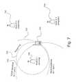
- FIG. 4is a diagram of a serving and neighboring node arrangement for a UE.
- a UE 410is illustrated as surrounded by one serving Node B 420 and six neighboring Node Bs 430 .
- LMUsmay or may not be installed (i.e., co-located or not co-located) at every Node B site.
- processing gain in primary detectionmay be designed such that at least an LMU at the serving site 420 will detect the TOA of the uplink frame.
- other sites, such as a neighboring Node B 430may also detect the signal.
- knowing the uplink frame TOA at any one sitemay provide a narrower search window for the other sites, which normally could not detect the uplink frame utilizing a primary processing algorithm, to search for the uplink frame marker TOA.
- the timing or range uncertaintymay be reduced to the size of the respective cell. For example, assume (i) that the serving Node B 420 has detected an uplink frame marker at the n th chip of the collected samples, (ii) that the average radius of the serving ceil is r (in chips), and (iii) that the distance between the serving Node B 420 and the neighboring Node B 430 is d (in chips).
- the search window for the secondary sitesmay be reduced from 38400 chips to only 2r chips.
- rmay be 64 chips whereby timing uncertainty corresponds to 128 chips. Timing uncertainty may be further reduced if sector geometry is considered in the respective calculations; therefore, such a reduced timing uncertainty may assist in implementing a high gain detection algorithm at the secondary sites.
- An exemplary primary detection process utilized in embodiments of the present subject mattermay employ non-coherent integration techniques disclosed in Yousef, N., et al., “Robust Wireless Location Over Fading Channels.” IEEE Transactions on Vehicular Technology, Vol. 52, No. 1, January 2003 and/or Tsui, J., “Fundamentals of Global Positioning System Receivers: A Software Approach,” 2nd ed. 2005, the entirety of each are incorporated herein by reference.
- a more robust detection metricmay be utilized for peak detection and peak quality estimation. For example, uplink DPCCH pilot bits are distributed among 15 slots of the periodic frame.
- Each reference slot(containing non-zero values for the pilot bits and zero for the remaining bits) may be correlated against corresponding segments of the captured data so that the fully overlapped correlation results are exactly one frame (e.g., 15 slots) long.
- This correlation processmay be conducted for a predetermined number of slots (e.g., 15, 30, and 60 slots, etc.).
- the results of these one frame long correlation outputsmay then be summed after converting the correlation samples into other metrics, e.g., magnitude or square of magnitude.
- An analysis of this techniquecan be found in sections 10.6 and 10.7 of Tsui. J., “Fundamentals of Global Positioning System Receivers: A Software Approach,” 2nd ed. 2005.
- the output of this exemplary non-coherent integration processis shown in FIG.
- a peak 510 of 5.85*10 4is shown utilizing this exemplary process.
- An exemplary peak detection and threshold setting techniqueis discussed in section 10.13 of Tsui, et al. This approach, however, is dependent upon automatic gain control (“AGC”) performance of the data collection device, is dependent upon the number of non-coherent additions, and requires noise power measurement.
- AGCautomatic gain control
- another metric, demeaned peak to standard deviation ratiomay be employed for peak detection in the primary processing.
- demeaned peak to standard deviation ratio(e.g., (peak-mean)/std)
- This metricdoes not require noise power measurement, is independent of the number of non-coherent additions, and is more robust to AGC fluctuations.
- Non-coherent additions of the magnitude (or magnitude squared) of correlation resultselevates the noise level in the summed correlation result.
- the demeaned peak to standard deviation ratio metricmay be indicative of the distinctness of the peak regardless of how much the mean is elevated.
- An alternative embodimentmay narrow the correlation peak search window in another manner.
- the UEmay transmit an uplink dedicated physical control channel/dedicated physical data channel (“DPCCH/DPDCH”) frame 1024 ⁇ 148 chips after the reception of the first detected path (in time) of the corresponding downlink dedicated physical channel (“DPCH”) or fractional dedicated physical channel (“F-DPCH”) frame. Therefore, if the downlink DPCH or F-DPCH frame timing is known at a LMU co-located with the serving site, the correlation peak search window may be reduced from 38400 chips to 148*2+r max chips, where r max represents the maximum search range in units of chips. For a large radius UMTS cell, r max may be 64 chips and the search window 360 chips.
- Determination of the timing of downlink DPCHmay be a function of the relationships of the primary common control physical channel (“P-CCPCH”) and the DPCH/F-DPCH. These relationships are described in section 7.1 of 3GPP TS 25.211 V7.0.0 (2006-03) and incorporated herein by reference.
- P-CCPCHprimary common control physical channel
- One method of obtaining P-CCPCH timing that may be implemented in the LMUis described in Annex C of 3GPP TS 25.214 V7.1.0 (2006-06) and is incorporated herein by reference.
- the offset between P-CCPCH and DPCH/F-DPCHis known to the RRC and is provided to the UE as discussed in IE 10.3.6.21 and 10.3.6.23ob of 3GPP TS 25.331 V7.4.0 (2007-03) and incorporated herein by reference.
- An exemplary networkmay provide this information as part of the tipping information to the SMLC, or the information may be obtained from the respective communication links.
- the LMUs 310may provide the detected peak information to the GCS 306 whereby the GCS 306 selects the best primary site depending upon the signal quality. After the primary site is chosen, the GCS 306 may then determine the distance between the selected primary site and the secondary sites. The GCS 306 may then provide the primary peak location and primary to neighbor site distances to the neighbor sites for secondary processing.
- the ambiguity function method described in Stein, S., “Algorithms for Ambiguity Function Processing,” IEEE Transactions on Acoustics, Speech, and Signal Processing, Vol. ASSP-29, No. 3, June 1981, the entirety of which is incorporated herein by reference,may be employed to perform coherent integration for different frequency offsets. This is an effective technique for detecting peaks if the signal is coherent over a collection duration.
- the secondary algorithmmay process signals of the order of seconds, and field tests have shown that signals may be incoherent over such a long span of time.
- FIG. 6is a graph showing a non-coherently added ambiguity matrix applied to real UMTS data according to an embodiment of the present subject matter.
- both the coherent and non-coherent methodsmay be employed during secondary processing in another embodiment of the present subject matter.
- all the collected signal sampleswere coherently integrated using the decimation technique described in Stein, “Algorithms for Ambiguity Function Processing.”
- the datawas segmented into smaller portions, and the coherent ambiguity function of each portion was non-coherently integrated. This process was repeated for different sizes of data segments. Since the demeaned peak to standard ratio metric does not depend upon number of non-coherent integrations, this metric may be employed to compare and identify the best peak among different non-coherent and coherent integration results.
- An advantage of embodiments employing this processis a higher probability of signal detection.
- the secondary processing algorithmgenerally has more processing gain than the primary processing algorithm; therefore, the primary site may, in certain embodiments, perform the secondary processing.
- a UE's range from a serving site or nodemay be estimated according to the systems and methods described in co-pending and related U.S. application Ser. No. 11/984,207, the entirety of which is incorporated herein by reference.
- each LMUmay determine the UE's range under the assumption that the LMU is located at the serving site or node. The range estimation of only the serving site or node is a valid range; however, range estimations from neighboring sites or nodes provide downlink slot marker offsets between base stations.
- the LMUsmay provide the GCS with the estimated range, TOA, and/or TOA quality from secondary processing.
- FIGS. 7 and 8are pictorial representations of a system and method for location of a UE according to embodiments of the present subject matter.
- a GCSmay utilize the TOA and range information to determine the location of a UE 702 .
- FIG. 8if measurements are available from only two LMUs 740 , 742 , there will be one range ring 830 and one hyperbola 810 , which intersect at two points.
- sector geometry 820(e.g., an intersecting point may be outside a serving sector and may be eliminated as the UE's location) may be utilized to eliminate one of the intersecting points as the location of the UE 702 .
- the intersection of the range ring and sector axismay be considered as the location of the UE 702 .
- the range ring computationmay also be based on the assumption that the downlink receive and uplink transmit time difference is 1024 chips. During handover, however, the downlink receive and uplink transmit time difference may not be 1024 chips, but the UE is likely to be near the cell edge and the uplink signal is usually detected by multiple LMUs.
- a UE's range estimationmay provide the actual transmit time of the UE, and the TOA information at the neighbor may be converted into range estimation.
- the network measured range ringmay be combined with LMU determined UTDOA hyperbolas.
- the tipping informationincludes the IE 9.2.2.31 of 3GPP TS 25.453 V7.6.0 (2007-03), incorporated herein by reference
- the range of the UEmay be determined from the Round Trip Time (“RTT”) and UE Rx-Tx Time Difference Type 2 parameters. If the above two parameters are converted into units of chips, the range of the UE from the serving site may be represented as (RTT-UE Rx-Tx Time Difference Type 2)/2 in chips.
- the range informationmay then be combined with the UTDOA hyperbolas to provide better location accuracy and yield.
- the IE 9.2.2.31is a part of a POSITION CALCULATION REQUEST of the lupc interface
- the standardized interface for tipping informationthis exemplary embodiment of the present subject matter may provide yet another novel approach.
- FIG. 9is an algorithm according to an embodiment of the present subject matter.
- a method for estimating a location of a wireless device 900 in a wireless communication system having a plurality of nodes and a plurality of LMUsis provided.
- the LMUsmay or may not be co-located with respective nodes.
- An exemplary communication systemmay be but is not limited to a UMTS network. WiMax network, GSM network, OFDMA network, WiFi network, and CDMA network.
- the systemmay also operate under a standard such as IS-95, EVDO, CDMA2000, LTE and 1 ⁇ RTT.
- Exemplary nodesmay be base stations, base station sectors, and combinations thereof.
- a plurality of signal samples from a first wireless device and a second wireless devicemay be collected by one or more LMUs in a first search window.
- Exemplary signal samplesmay represent both uplink and downlink spectrums.
- the first wireless devicemay be a UE and the second wireless device a Node B.
- a first TOAmay be determined from the plural signal samples at step 920 , and a second search window determined as a function of the first TOA at step 930 .
- the first TOAmay be determined by recreating an uplink pilot signal in at least one LMU and correlating the recreated uplink pilot signal against the plural signal samples.
- the second search windowmay be determined as a function of downlink dedicated physical channel frame timing or fractional dedicated channel frame timing. In another embodiment, the second search window may be determined as a function of round trip time and Rx-Tx time difference type 2 parameters.
- a second TOAmay be determined from the plural signal samples in the second search window.
- An exemplary TOAmay be an uplink signal TOA.
- a range estimate of the wireless devicemay be determined at step 950 , and an estimated location of the wireless device determined as a function of the first TOA, the second TOA, or range estimate and second TOA at step 960 .
- the range estimatemay be determined by comparing uplink and downlink frame markers in the plural signal samples.
- the estimated location of the wireless devicemay also be determined as a function of a value selected from the group consisting of sector geometry and sector axis in another embodiment.
- the processmay begin by providing a request to a geolocation control server to locate the wireless device in the communication system. This request may include tipping information provided by the communication system or the tipping information may be extracted from messages exchanged between the wireless device and a node.
- FIG. 10is an algorithm according to another embodiment of the present subject matter.
- a method for estimating a location of a wireless device 1000 in a wireless communication system having a plurality of nodes and a plurality of LMUsis provided.
- Exemplary nodesmay be base stations, base station sectors, and combinations thereof, and the LMUs may or may not be co-located with respective nodes.
- a set of signal samples from a first wireless device and a second wireless devicemay be collected by one or more LMUs in a search window determined as a function of a first uplink TOA from a first node.
- a second uplink TOAmay be determined at a second node or an LMU from the set of signal samples at step 1020 .
- the search windowmay be determined as a function of sector geometry.
- the first nodemay be a serving node and the second node a neighboring node.
- the first nodemay be a neighboring node and the second node a serving node or neighboring node.
- a range estimate of the wireless devicemay be determined, and at step 1040 an estimated location of the wireless device determined as a function of the first uplink TOA, the second uplink TOA, or the range estimate and second TOA.
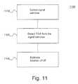
- FIG. 11is an algorithm according to yet another embodiment of the present subject matter.
- a method for estimating a location of a wireless device 1100is provided.
- signal samples from a wireless devicemay be collected by one or more LMUs, and at step 1120 a TOA detected from the signal samples where the TOA is detected by segmenting the collected signal samples to a predetermined length, determining an ambiguity function or correlation for each segment, and adding the ambiguity functions or correlations to detect a TOA.
- the TOAmay be detected by determining a mixing product of the collected signal samples, decimating the mixing product, segmenting the decimated product to predetermined lengths, determining ambiguity functions for each segment, and adding the ambiguity functions to detect a TOA.
- a demeaned peak to standard deviation ratiomay be applied to the added ambiguity functions and/or correlations.
- the ambiguity functions and/or correlationsmay be coherently or non-coherently added.
- an estimated location of the wireless devicemay be determined as a function of the TOA.
- a further embodiment of the present subject mattermay also select a TOA as a function of a detection threshold or quality.
- FIG. 12is an algorithm according to one embodiment of the present subject matter.
- a method for estimating a location of a wireless device 1200is provided.
- signal samplesmay be collected from a wireless device by one or more LMUs, and at step 1220 a TOA detected from the signal samples where the TOA is detected without regard to the noise and gain variation in the collected signal samples.
- an estimated location of the wireless devicemay be determined as a function of the TOA.
- FIG. 13is an algorithm according to an embodiment of the present subject matter.
- a method for estimating a location of a wireless device 1310 in a wireless communication system having a plurality of nodes and a plurality of LMUsis provided.
- a set of signal samples from a first wireless device and a second wireless devicemay be collected by one or more LMUs in a search window determined as a function of a first uplink TOA from a first node.
- a second uplink TOAmay be detected at a second node or LMU from the set of signal samples by a plurality of non-coherent additions of ambiguity functions.
- the second TOAmay be detected by segmenting the collected signal samples to a predetermined length, determining an ambiguity function or correlation for each segment, and adding the ambiguity functions or correlations to detect the TOA. These steps may be iteratively repeated for different sized portions. A demeaned peak to standard deviation ratio may be applied to the added ambiguity functions or correlations.
- the second TOAmay be detected by determining a mixing product of the collected signal samples, decimating the mixing product, segmenting the decimated product to predetermined lengths, determining ambiguity functions for each segment, and adding the ambiguity functions to detect the TOA. These steps may also be iteratively repeated for different sized portions.
- a demeaned peak to standard deviation ratiomay be applied to the added ambiguity functions.
- a range estimate of the wireless devicemay be determined at step 1330 and at step 1340 , an estimated location of the wireless device determined as a function of the first uplink TOA, the second uplink TOA, or the range estimate and second TOA.
- One aspect of embodiments of the present subject matteris to combine non-coherent and coherent integration methods to achieve a high processing gain in practical applications. Furthermore, the location estimation accuracy may be augmented by adding a range ring.
- FIGS. 1-13As shown by the various configurations and embodiments illustrated in FIGS. 1-13 , a system and method of UMTS UE location using uplink dedicated physical control and downlink synchronization channels have been described.
Landscapes
- Engineering & Computer Science (AREA)
- Computer Networks & Wireless Communication (AREA)
- Signal Processing (AREA)
- Physics & Mathematics (AREA)
- General Physics & Mathematics (AREA)
- Radar, Positioning & Navigation (AREA)
- Remote Sensing (AREA)
- Mobile Radio Communication Systems (AREA)
Abstract
Description
| TABLE 1 |
| DPCCH Fields |
| Channel | ||||||||||
| Slot | Channel | Symbol | Transmitted | |||||||
| Form | Bit Rate | Rate | Slots per | |||||||
| at #i | (kbps) | (ksps) | SF | Bits/Frame | Bits/Slot | Npilot | NTPC | NTFCI | NFBI | radio frame |
| 0 | 15 | 15 | 256 | 150 | 10 | 6 | 2 | 2 | 0 | 15 |
| 0A | 15 | 15 | 256 | 150 | 10 | 5 | 2 | 3 | 0 | 10-14 |
| 0B | 15 | 15 | 256 | 150 | 10 | 4 | 2 | 4 | 0 | 8-9 |
| 1 | 15 | 15 | 256 | 150 | 10 | 8 | 2 | 0 | 0 | 8-15 |
| 2 | 15 | 15 | 256 | 150 | 10 | 5 | 2 | 2 | 1 | 15 |
| 2A | 15 | 15 | 256 | 150 | 10 | 4 | 2 | 3 | 1 | 10-14 |
| 2B | 15 | 15 | 256 | 150 | 10 | 3 | 2 | 4 | 1 | 8-9 |
| 3 | 15 | 15 | 256 | 150 | 10 | 7 | 2 | 0 | 1 | 8-15 |
Claims (42)
Priority Applications (5)
| Application Number | Priority Date | Filing Date | Title |
|---|---|---|---|
| US12/246,156US8073463B2 (en) | 2008-10-06 | 2008-10-06 | System and method of UMTS UE location using uplink dedicated physical control channel and downlink synchronization channel |
| CA2681105ACA2681105A1 (en) | 2008-10-06 | 2009-10-05 | System and method of umts ue location using uplink dedicated physical control channel and downlink synchronization channel |
| EP09172302AEP2173131A1 (en) | 2008-10-06 | 2009-10-06 | System and method of UMTS UE location using uplink dedicated physical control channel and downlink synchronization channel |
| US13/269,911US8331956B2 (en) | 2008-10-06 | 2011-10-10 | System and method of UMTS UE location using uplink dedicated physical control channel and downlink synchronization channel |
| US13/705,820US8554248B2 (en) | 2008-10-06 | 2012-12-05 | System and method of UMTS UE location using uplink dedicated physical control channel and downlink synchronization channel |
Applications Claiming Priority (1)
| Application Number | Priority Date | Filing Date | Title |
|---|---|---|---|
| US12/246,156US8073463B2 (en) | 2008-10-06 | 2008-10-06 | System and method of UMTS UE location using uplink dedicated physical control channel and downlink synchronization channel |
Related Child Applications (1)
| Application Number | Title | Priority Date | Filing Date |
|---|---|---|---|
| US13/269,911ContinuationUS8331956B2 (en) | 2008-10-06 | 2011-10-10 | System and method of UMTS UE location using uplink dedicated physical control channel and downlink synchronization channel |
Publications (2)
| Publication Number | Publication Date |
|---|---|
| US20100087204A1 US20100087204A1 (en) | 2010-04-08 |
| US8073463B2true US8073463B2 (en) | 2011-12-06 |
Family
ID=41501592
Family Applications (3)
| Application Number | Title | Priority Date | Filing Date |
|---|---|---|---|
| US12/246,156Expired - Fee RelatedUS8073463B2 (en) | 2008-10-06 | 2008-10-06 | System and method of UMTS UE location using uplink dedicated physical control channel and downlink synchronization channel |
| US13/269,911ActiveUS8331956B2 (en) | 2008-10-06 | 2011-10-10 | System and method of UMTS UE location using uplink dedicated physical control channel and downlink synchronization channel |
| US13/705,820Expired - Fee RelatedUS8554248B2 (en) | 2008-10-06 | 2012-12-05 | System and method of UMTS UE location using uplink dedicated physical control channel and downlink synchronization channel |
Family Applications After (2)
| Application Number | Title | Priority Date | Filing Date |
|---|---|---|---|
| US13/269,911ActiveUS8331956B2 (en) | 2008-10-06 | 2011-10-10 | System and method of UMTS UE location using uplink dedicated physical control channel and downlink synchronization channel |
| US13/705,820Expired - Fee RelatedUS8554248B2 (en) | 2008-10-06 | 2012-12-05 | System and method of UMTS UE location using uplink dedicated physical control channel and downlink synchronization channel |
Country Status (3)
| Country | Link |
|---|---|
| US (3) | US8073463B2 (en) |
| EP (1) | EP2173131A1 (en) |
| CA (1) | CA2681105A1 (en) |
Cited By (6)
| Publication number | Priority date | Publication date | Assignee | Title |
|---|---|---|---|---|
| US20110070892A1 (en)* | 2009-09-21 | 2011-03-24 | Andrew Llc | System and method for a high throughput gsm location solution |
| US20120028653A1 (en)* | 2008-10-06 | 2012-02-02 | Andrew LLC. | System and method of umts ue location using uplink dedicated physical control channel and downlink synchronization channel |
| US20120136991A1 (en)* | 2010-11-29 | 2012-05-31 | Motorola Mobility, Inc. | Method and device for improving a browsing experience |
| US8472876B1 (en)* | 2009-09-30 | 2013-06-25 | Sprint Spectrum L.P. | Methods and systems for presenting the time of the most recently detected presence of a personal area network device |
| US20150163767A1 (en)* | 2013-12-10 | 2015-06-11 | At&T Intellectual Property I, L.P. | Dynamic network configuration based on passive location analytics |
| US9509473B2 (en) | 2009-08-14 | 2016-11-29 | Samsung Electroics Co., Ltd. | Method and device for sending and receiving a reference signal |
Families Citing this family (23)
| Publication number | Priority date | Publication date | Assignee | Title |
|---|---|---|---|---|
| US7783299B2 (en) | 1999-01-08 | 2010-08-24 | Trueposition, Inc. | Advanced triggers for location-based service applications in a wireless location system |
| JP4897038B2 (en)* | 2006-03-20 | 2012-03-14 | ケイティーフリーテル カンパニー リミテッド | Traffic information measuring method and system using CDMA network |
| WO2010096399A2 (en)* | 2009-02-17 | 2010-08-26 | Andrew Llc | Method and system for integrated timing measurements |
| US8213957B2 (en)* | 2009-04-22 | 2012-07-03 | Trueposition, Inc. | Network autonomous wireless location system |
| WO2011019356A1 (en)* | 2009-08-14 | 2011-02-17 | Andrew Llc | System and method for locating a wireless device in a wimax network using uplink signals |
| BR112012009800B1 (en)* | 2009-11-09 | 2020-12-08 | Zte Corporation | method for determining a slot format of a fractional dedicated physical control channel (f-dpch) and apparatus for determining a slot format of a fractional dedicated physical control channel (f-dpch) |
| US8472974B2 (en) | 2010-04-28 | 2013-06-25 | T-Mobile Usa, Inc. | Location continuity service for locating mobile devices using multiple access networks including wireless telecommunication networks |
| US9094927B2 (en) | 2010-04-28 | 2015-07-28 | T-Mobile Usa, Inc. | Location continuity service for locating mobile devices using multiple access networks including wireless telecommunication networks |
| US8384595B2 (en)* | 2010-12-16 | 2013-02-26 | Trueposition, Inc. | Position estimation through iterative inclusion of measurement data |
| US8331955B2 (en) | 2010-12-28 | 2012-12-11 | Trueposition, Inc. | Robust downlink frame synchronization schemes in CDMA wireless networks for geo-location |
| WO2013141771A1 (en)* | 2012-03-22 | 2013-09-26 | Telefonaktiebolaget L M Ericsson (Publ) | Enhancing uplink positioning |
| US9807560B2 (en)* | 2012-06-20 | 2017-10-31 | Telefonaktiebolaget L M Ericsson | Method and network node for enabling position determination of a user equipment measurement |
| US10588107B2 (en)* | 2012-10-26 | 2020-03-10 | Telefonaktiebolaget Lm Ericsson (Publ) | Methods of positioning in a system comprising measuring nodes with multiple receiving points |
| CN105580460A (en) | 2013-07-31 | 2016-05-11 | 慧与发展有限责任合伙企业 | Determining the location of a mobile device within a building |
| CN104540099A (en)* | 2014-12-31 | 2015-04-22 | 京信通信系统(中国)有限公司 | Terminal positioning method and evolutive serving mobile location center |
| US9560627B2 (en) | 2015-02-12 | 2017-01-31 | Qualcomm Incorporated | Assistance data for use in determining a position of a mobile device |
| US9733337B2 (en)* | 2015-08-28 | 2017-08-15 | Qualcomm Incorporated | Support of downlink positioning using coherent and non-coherent signal acquisition |
| US9622207B1 (en) | 2016-03-22 | 2017-04-11 | Qualcomm Incorporated | Wireless transmit station search window reduction |
| US9867007B1 (en) | 2016-11-29 | 2018-01-09 | Sprint Communications Company L.P. | Fine distance determination for user equipment (UE) that are served by wireless repeater chains |
| US10742271B2 (en)* | 2017-05-04 | 2020-08-11 | At&T Intellectual Property I, L.P. | Code block group configuration with code block segmentation for 5G systems |
| CN111970088B (en)* | 2018-01-30 | 2024-07-23 | 上海朗帛通信技术有限公司 | A method and device in a communication node for wireless communication |
| KR20200040676A (en)* | 2018-10-08 | 2020-04-20 | 한양대학교 산학협력단 | Apparatus and method for measuring position of target terminal in wireless communication system |
| US11234201B2 (en)* | 2019-06-10 | 2022-01-25 | Robotic Research Opco, Llc | Broadcast ranging radios for localization and timing |
Citations (49)
| Publication number | Priority date | Publication date | Assignee | Title |
|---|---|---|---|---|
| US4814751A (en) | 1987-02-27 | 1989-03-21 | Wildlife Materials, Inc. | Patient tracking system |
| US4845504A (en) | 1987-04-08 | 1989-07-04 | M/A-Com, Inc. | Mobile radio network for nationwide communications |
| US4891650A (en) | 1988-05-16 | 1990-01-02 | Trackmobile Inc. | Vehicle location system |
| US5056106A (en) | 1990-08-02 | 1991-10-08 | Wang James J | Golf course ranging and direction-finding system using spread-spectrum radiolocation techniques |
| US5218618A (en) | 1990-11-07 | 1993-06-08 | Hughes Aircraft Company | Cellular telephone service using spread spectrum transmission |
| US5245629A (en) | 1991-10-28 | 1993-09-14 | Motorola, Inc. | Method for compensating for capacity overload in a spread spectrum communication system |
| US5317323A (en) | 1993-03-05 | 1994-05-31 | E-Systems, Inc. | Passive high accuracy geolocation system and method |
| US5327144A (en) | 1993-05-07 | 1994-07-05 | Associated Rt, Inc. | Cellular telephone location system |
| US5365544A (en) | 1990-12-05 | 1994-11-15 | Interdigital Technology Corporation | CDMA communications and geolocation system and method |
| US5404376A (en) | 1993-09-09 | 1995-04-04 | Ericsson-Ge Mobile Communications Inc. | Navigation assistance for call handling in mobile telephone systems |
| US5506864A (en) | 1990-12-05 | 1996-04-09 | Interdigital Technology Corporation | CDMA communications and geolocation system and method |
| US5508708A (en) | 1995-05-08 | 1996-04-16 | Motorola, Inc. | Method and apparatus for location finding in a CDMA system |
| US5512908A (en) | 1994-07-08 | 1996-04-30 | Lockheed Sanders, Inc. | Apparatus and method for locating cellular telephones |
| US5515419A (en) | 1992-06-01 | 1996-05-07 | Trackmobile | Tracking system and method for tracking a movable object carrying a cellular phone unit, and integrated personal protection system incorporating the tracking system |
| US5519760A (en) | 1994-06-22 | 1996-05-21 | Gte Laboratories Incorporated | Cellular network-based location system |
| US5592180A (en) | 1992-08-20 | 1997-01-07 | Nexus1994 Limited | Direction finding and mobile location system for trunked mobile radio systems |
| US5614914A (en) | 1994-09-06 | 1997-03-25 | Interdigital Technology Corporation | Wireless telephone distribution system with time and space diversity transmission for determining receiver location |
| US5675344A (en) | 1996-06-28 | 1997-10-07 | Motorola, Inc. | Method and apparatus for locating a mobile station in a spread spectrum communication system |
| US5815538A (en) | 1993-06-25 | 1998-09-29 | Omniplex, Inc. | Method and apparatus for determining location of a subscriber device in a wireless cellular communications system |
| US5825887A (en) | 1995-12-28 | 1998-10-20 | Trimble Navigation Limited | Transmitting and receiving apparatus for full code correlation operation under encryption for satellite positioning system |
| US5900838A (en) | 1994-11-14 | 1999-05-04 | Lucent Technologies Inc. | Method and apparatus for a portable communication device to identify its own location |
| US5901358A (en) | 1997-07-15 | 1999-05-04 | Omnipoint Corporation | Mobile station locating system and method |
| US5914687A (en) | 1998-06-01 | 1999-06-22 | Litton Systems, Inc. | Combined phase-circle and multiplatform TDOA precision emitter location |
| US5920278A (en) | 1997-05-28 | 1999-07-06 | Gregory D. Gibbons | Method and apparatus for identifying, locating, tracking, or communicating with remote objects |
| US5945948A (en) | 1996-09-03 | 1999-08-31 | Motorola, Inc. | Method and apparatus for location finding in a communication system |
| US5959580A (en) | 1994-11-03 | 1999-09-28 | Ksi Inc. | Communications localization system |
| US5960341A (en) | 1994-09-28 | 1999-09-28 | U S West, Inc. | Positioning system having an RF-measurements databank |
| US5970413A (en) | 1996-06-06 | 1999-10-19 | Qualcomm Incorporated | Using a frequency that is unavailable for carrying telephone voice information traffic for determining the position of a mobile subscriber in a CDMA cellular telephone system |
| US5991329A (en) | 1995-06-30 | 1999-11-23 | Interdigital Technology Corporation | Automatic power control system for a code division multiple access (CDMA) communications system |
| US6047192A (en) | 1996-05-13 | 2000-04-04 | Ksi Inc. | Robust, efficient, localization system |
| US6097336A (en) | 1999-01-08 | 2000-08-01 | Trueposition, Inc. | Method for improving the accuracy of a wireless location system |
| US6108555A (en) | 1996-05-17 | 2000-08-22 | Ksi, Inc. | Enchanced time difference localization system |
| US6160511A (en) | 1999-09-30 | 2000-12-12 | Motorola, Inc. | Method and apparatus for locating a remote unit within a communication system |
| US6233459B1 (en) | 1997-04-10 | 2001-05-15 | The Atlantis Company, Limited, Japan | System for providing Geolocation of a mobile transceiver |
| US6246884B1 (en) | 1998-08-19 | 2001-06-12 | Sigmaone Communications Corporation | System and method for measuring and locating a mobile station signal in a wireless communication system |
| US6256494B1 (en)* | 1999-05-08 | 2001-07-03 | Motorola, Inc. | Method of and apparatus for estimating a characteristic of a signal |
| AU740903B2 (en) | 1999-01-23 | 2001-11-15 | Samsung Electronics Co., Ltd. | Device and method for tracking location of mobile telephone in mobile telecommunication network |
| US6334059B1 (en) | 1999-01-08 | 2001-12-25 | Trueposition, Inc. | Modified transmission method for improving accuracy for e-911 calls |
| US6356763B1 (en) | 1998-08-07 | 2002-03-12 | Telefonaktiebolaget Lm Ericsson (Publ) | Downlink observed time difference measurements |
| US6366241B2 (en) | 2000-06-26 | 2002-04-02 | Trueposition, Inc. | Enhanced determination of position-dependent signal characteristics of a wireless transmitter |
| US6456604B1 (en) | 1998-01-24 | 2002-09-24 | Samsung Electronics, Co., Ltd. | Data communication method in mobile communication system |
| US6463290B1 (en) | 1999-01-08 | 2002-10-08 | Trueposition, Inc. | Mobile-assisted network based techniques for improving accuracy of wireless location system |
| US20020155845A1 (en)* | 2001-04-23 | 2002-10-24 | Martorana Marc J. | Method and apparatus for high-accuracy position location using search mode ranging techniques |
| US20030054845A1 (en)* | 2001-08-30 | 2003-03-20 | Leonid Krasny | Enhanced time of arrival estimation using reduced complexity optimal processing |
| US20030086512A1 (en)* | 2001-10-29 | 2003-05-08 | Rick Roland R | Parameter estimator with dynamically variable search window size and/or placement |
| US6646604B2 (en) | 1999-01-08 | 2003-11-11 | Trueposition, Inc. | Automatic synchronous tuning of narrowband receivers of a wireless location system for voice/traffic channel tracking |
| US20060003695A1 (en) | 2002-10-16 | 2006-01-05 | Kennedy Joseph P Jr | System and method of operation for network overlay geolocation systemwith repeaters |
| US7190964B2 (en) | 2001-08-20 | 2007-03-13 | Telefonaktiebolaget Lm Ericsson (Publ) | Reverse link power control in 1xEV-DV systems |
| US20100039326A1 (en) | 2008-08-15 | 2010-02-18 | Trueposition, Inc. | Variable Coherence Integration for the Location of Weak Signals |
Family Cites Families (100)
| Publication number | Priority date | Publication date | Assignee | Title |
|---|---|---|---|---|
| US3150372A (en) | 1959-06-23 | 1964-09-22 | Motorola Inc | Computing system |
| US3659085A (en) | 1970-04-30 | 1972-04-25 | Sierra Research Corp | Computer determining the location of objects in a coordinate system |
| US4728959A (en) | 1986-08-08 | 1988-03-01 | Ventana Sciences Inc. | Direction finding localization system |
| JPH0567996A (en) | 1991-09-09 | 1993-03-19 | Nec Corp | Automobile telephone set system |
| US5372144A (en) | 1992-12-01 | 1994-12-13 | Scimed Life Systems, Inc. | Navigability improved guidewire construction and method of using same |
| US5465289A (en) | 1993-03-05 | 1995-11-07 | E-Systems, Inc. | Cellular based traffic sensor system |
| US5506863A (en) | 1993-08-25 | 1996-04-09 | Motorola, Inc. | Method and apparatus for operating with a hopping control channel in a communication system |
| US5594776A (en) | 1994-09-14 | 1997-01-14 | Ericsson Inc. | Efficient paging system |
| GB9508884D0 (en) | 1995-05-02 | 1995-06-21 | Telecom Sec Cellular Radio Ltd | Cellular radio system |
| US5870029A (en) | 1996-07-08 | 1999-02-09 | Harris Corporation | Remote mobile monitoring and communication system |
| WO1998009385A2 (en) | 1996-08-29 | 1998-03-05 | Cisco Technology, Inc. | Spatio-temporal processing for communication |
| US5945949A (en) | 1997-01-13 | 1999-08-31 | Lucent Technologies Inc. | Mobile station position determination in a wireless communication system |
| US5973643A (en) | 1997-04-11 | 1999-10-26 | Corsair Communications, Inc. | Method and apparatus for mobile emitter location |
| US6101178A (en) | 1997-07-10 | 2000-08-08 | Ksi Inc. | Pseudolite-augmented GPS for locating wireless telephones |
| US5987329A (en) | 1997-07-30 | 1999-11-16 | Ericsson Inc | System and method for mobile telephone location measurement using a hybrid technique |
| US5952969A (en) | 1997-08-18 | 1999-09-14 | Telefonakiebolaget L M Ericsson (Publ) | Method and system for determining the position of mobile radio terminals |
| US6011974A (en) | 1997-09-23 | 2000-01-04 | Telefonaktiebolaget L M Ericsson (Publ) | Method and system for determining position of a cellular mobile terminal |
| FR2771517B1 (en) | 1997-11-27 | 2001-12-14 | Dassault Electronique | ELECTRO-OPTICAL DEVICE, PARTICULARLY FOR OPTICAL DISTRIBUTION |
| US6097959A (en) | 1998-01-29 | 2000-08-01 | Ericsson Inc. | System and method for accurate positioning of mobile terminals |
| US6201499B1 (en) | 1998-02-03 | 2001-03-13 | Consair Communications | Time difference of arrival measurement system |
| US6014102A (en) | 1998-04-17 | 2000-01-11 | Motorola, Inc. | Method and apparatus for calibrating location finding equipment within a communication system |
| US6075826A (en) | 1998-05-13 | 2000-06-13 | Comsat Corporation | Method and apparatus for obtaining initial carrier and symbol phase estimates for use in synchronizing transmitting data |
| US6188351B1 (en) | 1998-08-13 | 2001-02-13 | Ericsson Inc. | Method for improving signal acquistion in a global positioning system receiver |
| US6311043B1 (en) | 1998-10-27 | 2001-10-30 | Siemens Aktiengesellschaft | Method and measurement configuration for measuring the characteristics of radio channels |
| GB9828216D0 (en) | 1998-12-21 | 1999-02-17 | Northern Telecom Ltd | A downlink beamforming approach for frequency division duplex cellular systems |
| US6782264B2 (en) | 1999-01-08 | 2004-08-24 | Trueposition, Inc. | Monitoring of call information in a wireless location system |
| WO2000041402A2 (en) | 1999-01-08 | 2000-07-13 | Trueposition, Inc. | A signal collection system |
| US6765531B2 (en) | 1999-01-08 | 2004-07-20 | Trueposition, Inc. | System and method for interference cancellation in a location calculation, for use in a wireless location system |
| US7783299B2 (en) | 1999-01-08 | 2010-08-24 | Trueposition, Inc. | Advanced triggers for location-based service applications in a wireless location system |
| US6873290B2 (en) | 1999-01-08 | 2005-03-29 | Trueposition, Inc. | Multiple pass location processor |
| AU4037499A (en) | 1999-05-05 | 2000-11-21 | Nokia Corporation | A method for positioning a mobile station |
| US6295455B1 (en) | 1999-06-11 | 2001-09-25 | Telefonaktiebolaget Lm Ericsson (Publ) | Methods and arrangements for locating a mobile telecommunications station |
| US6603761B1 (en) | 1999-09-17 | 2003-08-05 | Lucent Technologies Inc. | Using internet and internet protocols to bypass PSTN, GSM map, and ANSI-41 networks for wireless telephone call delivery |
| US6553322B1 (en) | 1999-09-29 | 2003-04-22 | Honeywell International Inc. | Apparatus and method for accurate pipeline surveying |
| US6191738B1 (en) | 1999-09-30 | 2001-02-20 | Motorola, Inc. | Method and apparatus for locating a remote unit within a communication system |
| US6490456B1 (en) | 1999-10-12 | 2002-12-03 | Lucent Technologies Inc. | Locating a mobile unit in a wireless time division multiple access system |
| US6571082B1 (en) | 1999-10-29 | 2003-05-27 | Verizon Laboratories Inc. | Wireless field test simulator |
| US6640106B2 (en) | 2001-09-20 | 2003-10-28 | Motorola, Inc. | Method and system for verifying the position of a mobile station using checkpoints |
| US6687507B2 (en) | 2000-05-03 | 2004-02-03 | Telefonaktiebolaget Lm Ericsson (Publ) | Time of arrival estimation for edge/GSM |
| US6501955B1 (en) | 2000-06-19 | 2002-12-31 | Intel Corporation | RF signal repeater, mobile unit position determination system using the RF signal repeater, and method of communication therefor |
| US6771969B1 (en) | 2000-07-06 | 2004-08-03 | Harris Corporation | Apparatus and method for tracking and communicating with a mobile radio unit |
| US6407703B1 (en) | 2000-08-07 | 2002-06-18 | Lockheed Martin Corporation | Multi-platform geolocation method and system |
| FI109839B (en) | 2000-08-22 | 2002-10-15 | Nokia Corp | A method for locating a mobile station |
| US7110774B1 (en) | 2000-10-27 | 2006-09-19 | Intel Corporation | Dual mode uplink/downlink location measurement and multi-protocol location measurement |
| US6470195B1 (en) | 2000-10-31 | 2002-10-22 | Raytheon Company | Method and apparatus for modeling a smart antenna in a network planning tool |
| BR0107383A (en)* | 2000-11-14 | 2002-11-05 | Symbol Technologies Inc | Wireless receiver station clock synchronization system and method |
| US6834234B2 (en) | 2000-11-22 | 2004-12-21 | Trimble Navigation, Limited | AINS land surveyor system with reprocessing, AINS-LSSRP |
| US6845240B2 (en) | 2000-12-11 | 2005-01-18 | Grayson Wireless | System and method for analog cellular radio geolocation |
| US6952158B2 (en) | 2000-12-11 | 2005-10-04 | Kennedy Jr Joseph P | Pseudolite positioning system and method |
| US6920329B2 (en) | 2001-01-16 | 2005-07-19 | Allen Telecom | Method and system for applying wireless geolocation technology |
| WO2002085057A1 (en) | 2001-04-06 | 2002-10-24 | Nokia Corporation | Location method and system |
| US6876859B2 (en) | 2001-07-18 | 2005-04-05 | Trueposition, Inc. | Method for estimating TDOA and FDOA in a wireless location system |
| US6871077B2 (en) | 2001-10-09 | 2005-03-22 | Grayson Wireless | System and method for geolocating a wireless mobile unit from a single base station using repeatable ambiguous measurements |
| US6748202B2 (en) | 2001-12-12 | 2004-06-08 | Nokia Corporation | Method, apparatus and system for synchronizing a cellular communication system to GPS time |
| US6987979B2 (en) | 2001-12-22 | 2006-01-17 | Telefonaktiebolaget Lm Ericsson (Publ) | Locating packet-switched mobile terminals using network initiated artificial cell hops |
| US6922170B2 (en) | 2002-01-24 | 2005-07-26 | Motorola, Inc. | Methods and apparatus for determining a direction of arrival in a wireless communication system |
| US6950664B2 (en) | 2002-01-24 | 2005-09-27 | Lucent Technologies Inc. | Geolocation using enhanced timing advance techniques |
| US6973320B2 (en) | 2002-04-29 | 2005-12-06 | Motorola, Inc. | Method and apparatus for locating a remote unit within a communication system |
| US8032149B2 (en) | 2002-08-29 | 2011-10-04 | Andrew Llc | Tasking and reporting method and implementation for wireless appliance location systems |
| US6889052B2 (en)* | 2002-08-30 | 2005-05-03 | Motorola, Inc. | Method and apparatus for generating time of arrival estimates for use in determining a location |
| US6996392B2 (en) | 2002-09-03 | 2006-02-07 | Trueposition, Inc. | E911 overlay solution for GSM, for use in a wireless location system |
| US7429951B2 (en) | 2002-10-16 | 2008-09-30 | Andrew Corporation | System and method for enhancing the accuracy of a location estimate |
| EP1568244B1 (en)* | 2002-12-02 | 2009-10-07 | Nokia Corporation | Estimation of a signal delay |
| US7162252B2 (en) | 2002-12-23 | 2007-01-09 | Andrew Corporation | Method and apparatus for supporting multiple wireless carrier mobile station location requirements with a common network overlay location system |
| US7358898B2 (en) | 2003-01-31 | 2008-04-15 | Andrew Corporation | Method for calibrating an AOA location system for all frequencies in a frequency hopping signal |
| US7405696B2 (en) | 2003-01-31 | 2008-07-29 | Andrew Corporation | Method for calibrating and AOA location system for frequency hopping air interfaces |
| US7379019B2 (en) | 2003-01-31 | 2008-05-27 | Andrew Corporation | Method for angle of arrival determination on frequency hopping air interfaces |
| US6859172B2 (en) | 2003-02-17 | 2005-02-22 | Global Business Software Development Technologies, Inc. | System and method for locating a mobile phone |
| ATE442750T1 (en) | 2003-03-03 | 2009-09-15 | Andrew Llc | INDEPENDENT CAPTURE AND TRACKING OF SIGNING CHANNEL ASSIGNMENTS OF A WIRELESS COMMUNICATION SYSTEM ON COMMUNICATION LINKS |
| US20040203921A1 (en) | 2003-03-21 | 2004-10-14 | Nicholas Bromhead | Sub-sector timing advance positions determinations |
| US7429914B2 (en) | 2003-06-04 | 2008-09-30 | Andrew Corporation | System and method for CDMA geolocation |
| US7623872B2 (en) | 2003-06-24 | 2009-11-24 | Andrew Corporation | Method for sparse network deployment accuracy enhancements |
| US7123928B2 (en) | 2003-07-21 | 2006-10-17 | Qualcomm Incorporated | Method and apparatus for creating and using a base station almanac for position determination |
| US7738836B2 (en) | 2003-09-26 | 2010-06-15 | Andrew Corporation | System and method of operation for network overlay geolocation system with repeaters using AM Golay Hadamard signatures |
| WO2005060669A2 (en) | 2003-12-19 | 2005-07-07 | Kennedy Joseph P | E-otd augmentation to u-tdoa location system |
| US7440762B2 (en) | 2003-12-30 | 2008-10-21 | Trueposition, Inc. | TDOA/GPS hybrid wireless location system |
| GB0410609D0 (en) | 2004-05-12 | 2004-06-16 | Nokia Corp | Locating mobile terminals |
| KR20070114286A (en) | 2005-02-11 | 2007-11-30 | 트루포지션, 인크. | Synchronization of transmit and receive base stations |
| US7427952B2 (en) | 2005-04-08 | 2008-09-23 | Trueposition, Inc. | Augmentation of commercial wireless location system (WLS) with moving and/or airborne sensors for enhanced location accuracy and use of real-time overhead imagery for identification of wireless device locations |
| US20060291577A1 (en) | 2005-05-26 | 2006-12-28 | Adrian Boariu | System and method for selecting pilot tone positions in communication systems |
| US7566971B2 (en) | 2005-05-27 | 2009-07-28 | Semiconductor Energy Laboratory Co., Ltd. | Semiconductor device and manufacturing method thereof |
| US8050691B2 (en)* | 2005-08-11 | 2011-11-01 | Telefonaktiebolaget L M Ericsson (Publ) | Method and arrangements in a mobile telecommunication network |
| US20070117573A1 (en) | 2005-11-04 | 2007-05-24 | Kennedy Joseph P Jr | System and method for generating geocoded data for network optimization under different network architectures and location technology conditions |
| US7689240B2 (en) | 2005-11-16 | 2010-03-30 | Trueposition, Inc. | Transmit-power control for wireless mobile services |
| US7593738B2 (en) | 2005-12-29 | 2009-09-22 | Trueposition, Inc. | GPS synchronization for wireless communications stations |
| US8150421B2 (en) | 2005-12-30 | 2012-04-03 | Trueposition, Inc. | User plane uplink time difference of arrival (U-TDOA) |
| US20090005061A1 (en) | 2005-12-30 | 2009-01-01 | Trueposition, Inc. | Location quality of service indicator |
| US20070155489A1 (en) | 2005-12-30 | 2007-07-05 | Frederic Beckley | Device and network enabled geo-fencing for area sensitive gaming enablement |
| US7844280B2 (en) | 2006-12-12 | 2010-11-30 | Trueposition, Inc. | Location of wideband OFDM transmitters with limited receiver bandwidth |
| US7920875B2 (en) | 2006-12-01 | 2011-04-05 | Trueposition, Inc. | Subscriptionless location of wireless devices |
| US7797000B2 (en) | 2006-12-01 | 2010-09-14 | Trueposition, Inc. | System for automatically determining cell transmitter parameters to facilitate the location of wireless devices |
| US7616155B2 (en) | 2006-12-27 | 2009-11-10 | Bull Jeffrey F | Portable, iterative geolocation of RF emitters |
| US8010079B2 (en) | 2006-12-28 | 2011-08-30 | Trueposition, Inc. | Emergency wireless location system including a wireless transceiver |
| US7848733B2 (en) | 2006-12-28 | 2010-12-07 | Trueposition, Inc. | Emergency wireless location system including a location determining receiver |
| US8478299B2 (en) | 2007-04-06 | 2013-07-02 | Hewlett-Packard Development Company, L.P. | System and methods for obtaining coarse location for a mobile device |
| US8242959B2 (en) | 2007-04-18 | 2012-08-14 | Trueposition, Inc. | Sparsed U-TDOA wireless location networks |
| US8041367B2 (en) | 2007-04-18 | 2011-10-18 | Trueposition, Inc. | Sparsed U-TDOA wireless location networks |
| US8140092B2 (en) | 2007-04-18 | 2012-03-20 | Trueposition, Inc. | Sparsed U-TDOA wireless location networks |
| US8045506B2 (en) | 2007-04-18 | 2011-10-25 | Trueposition, Inc. | Sparsed U-TDOA wireless location networks |
| US8073463B2 (en)* | 2008-10-06 | 2011-12-06 | Andrew, Llc | System and method of UMTS UE location using uplink dedicated physical control channel and downlink synchronization channel |
- 2008
- 2008-10-06USUS12/246,156patent/US8073463B2/ennot_activeExpired - Fee Related
- 2009
- 2009-10-05CACA2681105Apatent/CA2681105A1/ennot_activeAbandoned
- 2009-10-06EPEP09172302Apatent/EP2173131A1/ennot_activeWithdrawn
- 2011
- 2011-10-10USUS13/269,911patent/US8331956B2/enactiveActive
- 2012
- 2012-12-05USUS13/705,820patent/US8554248B2/ennot_activeExpired - Fee Related
Patent Citations (59)
| Publication number | Priority date | Publication date | Assignee | Title |
|---|---|---|---|---|
| US4814751A (en) | 1987-02-27 | 1989-03-21 | Wildlife Materials, Inc. | Patient tracking system |
| US4845504A (en) | 1987-04-08 | 1989-07-04 | M/A-Com, Inc. | Mobile radio network for nationwide communications |
| US4891650A (en) | 1988-05-16 | 1990-01-02 | Trackmobile Inc. | Vehicle location system |
| US5056106A (en) | 1990-08-02 | 1991-10-08 | Wang James J | Golf course ranging and direction-finding system using spread-spectrum radiolocation techniques |
| US5218618A (en) | 1990-11-07 | 1993-06-08 | Hughes Aircraft Company | Cellular telephone service using spread spectrum transmission |
| US5365544A (en) | 1990-12-05 | 1994-11-15 | Interdigital Technology Corporation | CDMA communications and geolocation system and method |
| US5506864A (en) | 1990-12-05 | 1996-04-09 | Interdigital Technology Corporation | CDMA communications and geolocation system and method |
| US5245629A (en) | 1991-10-28 | 1993-09-14 | Motorola, Inc. | Method for compensating for capacity overload in a spread spectrum communication system |
| US5515419A (en) | 1992-06-01 | 1996-05-07 | Trackmobile | Tracking system and method for tracking a movable object carrying a cellular phone unit, and integrated personal protection system incorporating the tracking system |
| US5592180A (en) | 1992-08-20 | 1997-01-07 | Nexus1994 Limited | Direction finding and mobile location system for trunked mobile radio systems |
| US5317323A (en) | 1993-03-05 | 1994-05-31 | E-Systems, Inc. | Passive high accuracy geolocation system and method |
| US5327144A (en) | 1993-05-07 | 1994-07-05 | Associated Rt, Inc. | Cellular telephone location system |
| US5815538A (en) | 1993-06-25 | 1998-09-29 | Omniplex, Inc. | Method and apparatus for determining location of a subscriber device in a wireless cellular communications system |
| US5404376A (en) | 1993-09-09 | 1995-04-04 | Ericsson-Ge Mobile Communications Inc. | Navigation assistance for call handling in mobile telephone systems |
| US5519760A (en) | 1994-06-22 | 1996-05-21 | Gte Laboratories Incorporated | Cellular network-based location system |
| US5512908A (en) | 1994-07-08 | 1996-04-30 | Lockheed Sanders, Inc. | Apparatus and method for locating cellular telephones |
| US5614914A (en) | 1994-09-06 | 1997-03-25 | Interdigital Technology Corporation | Wireless telephone distribution system with time and space diversity transmission for determining receiver location |
| US5960341A (en) | 1994-09-28 | 1999-09-28 | U S West, Inc. | Positioning system having an RF-measurements databank |
| US6288675B1 (en) | 1994-11-03 | 2001-09-11 | Ksi, Inc. | Single station communications localization system |
| US5959580A (en) | 1994-11-03 | 1999-09-28 | Ksi Inc. | Communications localization system |
| US6127975A (en) | 1994-11-03 | 2000-10-03 | Ksi, Incorporated | Single station communications localization system |
| US6288676B1 (en) | 1994-11-03 | 2001-09-11 | Ksi, Inc. | Apparatus and method for single station communications localization |
| US5900838A (en) | 1994-11-14 | 1999-05-04 | Lucent Technologies Inc. | Method and apparatus for a portable communication device to identify its own location |
| US5508708A (en) | 1995-05-08 | 1996-04-16 | Motorola, Inc. | Method and apparatus for location finding in a CDMA system |
| US5736964A (en) | 1995-05-08 | 1998-04-07 | Motorola, Inc. | Method and apparatus for location finding in a CDMA system |
| US5991329A (en) | 1995-06-30 | 1999-11-23 | Interdigital Technology Corporation | Automatic power control system for a code division multiple access (CDMA) communications system |
| US5825887A (en) | 1995-12-28 | 1998-10-20 | Trimble Navigation Limited | Transmitting and receiving apparatus for full code correlation operation under encryption for satellite positioning system |
| US6047192A (en) | 1996-05-13 | 2000-04-04 | Ksi Inc. | Robust, efficient, localization system |
| US6108555A (en) | 1996-05-17 | 2000-08-22 | Ksi, Inc. | Enchanced time difference localization system |
| US6119013A (en) | 1996-05-17 | 2000-09-12 | Ksi, Inc. | Enhanced time-difference localization system |
| US5970413A (en) | 1996-06-06 | 1999-10-19 | Qualcomm Incorporated | Using a frequency that is unavailable for carrying telephone voice information traffic for determining the position of a mobile subscriber in a CDMA cellular telephone system |
| US5675344A (en) | 1996-06-28 | 1997-10-07 | Motorola, Inc. | Method and apparatus for locating a mobile station in a spread spectrum communication system |
| US5945948A (en) | 1996-09-03 | 1999-08-31 | Motorola, Inc. | Method and apparatus for location finding in a communication system |
| US6233459B1 (en) | 1997-04-10 | 2001-05-15 | The Atlantis Company, Limited, Japan | System for providing Geolocation of a mobile transceiver |
| US5920278A (en) | 1997-05-28 | 1999-07-06 | Gregory D. Gibbons | Method and apparatus for identifying, locating, tracking, or communicating with remote objects |
| US5901358A (en) | 1997-07-15 | 1999-05-04 | Omnipoint Corporation | Mobile station locating system and method |
| US6456604B1 (en) | 1998-01-24 | 2002-09-24 | Samsung Electronics, Co., Ltd. | Data communication method in mobile communication system |
| US5914687A (en) | 1998-06-01 | 1999-06-22 | Litton Systems, Inc. | Combined phase-circle and multiplatform TDOA precision emitter location |
| US6356763B1 (en) | 1998-08-07 | 2002-03-12 | Telefonaktiebolaget Lm Ericsson (Publ) | Downlink observed time difference measurements |
| US6246884B1 (en) | 1998-08-19 | 2001-06-12 | Sigmaone Communications Corporation | System and method for measuring and locating a mobile station signal in a wireless communication system |
| US6400320B1 (en) | 1999-01-08 | 2002-06-04 | Trueposition, Inc. | Antenna selection method for a wireless location system |
| US6463290B1 (en) | 1999-01-08 | 2002-10-08 | Trueposition, Inc. | Mobile-assisted network based techniques for improving accuracy of wireless location system |
| US6317604B1 (en) | 1999-01-08 | 2001-11-13 | Trueposition, Inc. | Centralized database system for a wireless location system |
| US6317081B1 (en) | 1999-01-08 | 2001-11-13 | Trueposition, Inc. | Internal calibration method for receiver system of a wireless location system |
| US6334059B1 (en) | 1999-01-08 | 2001-12-25 | Trueposition, Inc. | Modified transmission method for improving accuracy for e-911 calls |
| US6184829B1 (en) | 1999-01-08 | 2001-02-06 | Trueposition, Inc. | Calibration for wireless location system |
| US6646604B2 (en) | 1999-01-08 | 2003-11-11 | Trueposition, Inc. | Automatic synchronous tuning of narrowband receivers of a wireless location system for voice/traffic channel tracking |
| US6281834B1 (en) | 1999-01-08 | 2001-08-28 | Trueposition, Inc. | Calibration for wireless location system |
| US6097336A (en) | 1999-01-08 | 2000-08-01 | Trueposition, Inc. | Method for improving the accuracy of a wireless location system |
| AU740903B2 (en) | 1999-01-23 | 2001-11-15 | Samsung Electronics Co., Ltd. | Device and method for tracking location of mobile telephone in mobile telecommunication network |
| US6256494B1 (en)* | 1999-05-08 | 2001-07-03 | Motorola, Inc. | Method of and apparatus for estimating a characteristic of a signal |
| US6160511A (en) | 1999-09-30 | 2000-12-12 | Motorola, Inc. | Method and apparatus for locating a remote unit within a communication system |
| US6366241B2 (en) | 2000-06-26 | 2002-04-02 | Trueposition, Inc. | Enhanced determination of position-dependent signal characteristics of a wireless transmitter |
| US20020155845A1 (en)* | 2001-04-23 | 2002-10-24 | Martorana Marc J. | Method and apparatus for high-accuracy position location using search mode ranging techniques |
| US7190964B2 (en) | 2001-08-20 | 2007-03-13 | Telefonaktiebolaget Lm Ericsson (Publ) | Reverse link power control in 1xEV-DV systems |
| US20030054845A1 (en)* | 2001-08-30 | 2003-03-20 | Leonid Krasny | Enhanced time of arrival estimation using reduced complexity optimal processing |
| US20030086512A1 (en)* | 2001-10-29 | 2003-05-08 | Rick Roland R | Parameter estimator with dynamically variable search window size and/or placement |
| US20060003695A1 (en) | 2002-10-16 | 2006-01-05 | Kennedy Joseph P Jr | System and method of operation for network overlay geolocation systemwith repeaters |
| US20100039326A1 (en) | 2008-08-15 | 2010-02-18 | Trueposition, Inc. | Variable Coherence Integration for the Location of Weak Signals |
Non-Patent Citations (7)
| Title |
|---|
| 3GPP TS 25.214 Version 7.1.0 Technical Specification, Universal Mobile Telecommunications System (UMTS) Physical Layer Procedures, Jun. 2006. |
| 3GPP TS 25.331 Version 7.4.0 Technical Specification, Universal Mobile Telecommunications System (UMTS) Radio Resource Control (RRC) Protocol Specification, Mar. 2007. |
| 3GPP TS 25.543 Version 7.6.0 Technical Specification, Universal Mobile Telecommunications System (UMTS) Physical Channels and Mapping of Transport Channels onto Physical Channels (FDD), Mar. 2006. |
| 3GPP TS 25.543 Version 7.6.0 Technical Specification, Universal Mobile Telecommunications System (UMTS) UTRAN Iupc Interface Positioning Calculation Application Part (PCAP) Signalling, Mar. 2007. |
| Stein, Seymour, "Algorithms for Ambiguity Function Processing," IEEE Transactions on Acoustics, Speech and Signal Processing, vol. ASSP-29, No. 3, Jun. 1981. |
| Tsui, James Bao-Yen, "Fundamentals of Global Positioning System Receivers A Software Approach," Wiley-Interscience, 2nd Edition, 2005, Sections 10.6, 10.7 and 10.13, pp. 231-235, 247-256. |
| Yousef, Nabil, et al., "Robust Wireless Location Over Fading Channels," IEEE Transactions on Vehicular Technology, vol. 52, No. 1, Jan. 2003. |
Cited By (12)
| Publication number | Priority date | Publication date | Assignee | Title |
|---|---|---|---|---|
| US20120028653A1 (en)* | 2008-10-06 | 2012-02-02 | Andrew LLC. | System and method of umts ue location using uplink dedicated physical control channel and downlink synchronization channel |
| US8331956B2 (en)* | 2008-10-06 | 2012-12-11 | Andrew Llc | System and method of UMTS UE location using uplink dedicated physical control channel and downlink synchronization channel |
| US20130095853A1 (en)* | 2008-10-06 | 2013-04-18 | Tariqul Islam | System and Method of UMTS UE Location Using Uplink Dedicated Physical Control Channel And Downlink Synchronization Channel |
| US8554248B2 (en)* | 2008-10-06 | 2013-10-08 | Andrew Llc | System and method of UMTS UE location using uplink dedicated physical control channel and downlink synchronization channel |
| US9509473B2 (en) | 2009-08-14 | 2016-11-29 | Samsung Electroics Co., Ltd. | Method and device for sending and receiving a reference signal |
| US20110070892A1 (en)* | 2009-09-21 | 2011-03-24 | Andrew Llc | System and method for a high throughput gsm location solution |
| US8472876B1 (en)* | 2009-09-30 | 2013-06-25 | Sprint Spectrum L.P. | Methods and systems for presenting the time of the most recently detected presence of a personal area network device |
| US20120136991A1 (en)* | 2010-11-29 | 2012-05-31 | Motorola Mobility, Inc. | Method and device for improving a browsing experience |
| US8886811B2 (en)* | 2010-11-29 | 2014-11-11 | Motorola Mobility Llc | Method and device for improving a browsing experience |
| US20150163767A1 (en)* | 2013-12-10 | 2015-06-11 | At&T Intellectual Property I, L.P. | Dynamic network configuration based on passive location analytics |
| US9591603B2 (en)* | 2013-12-10 | 2017-03-07 | At&T Intellectual Property I, L.P. | Dynamic network configuration based on passive location analytics |
| US10405295B2 (en) | 2013-12-10 | 2019-09-03 | At&T Intellectual Property I, L.P. | Dynamic network configuration based on passive location analytics |
Also Published As
| Publication number | Publication date |
|---|---|
| US8331956B2 (en) | 2012-12-11 |
| CA2681105A1 (en) | 2010-04-06 |
| US8554248B2 (en) | 2013-10-08 |
| EP2173131A1 (en) | 2010-04-07 |
| US20130095853A1 (en) | 2013-04-18 |
| US20120028653A1 (en) | 2012-02-02 |
| US20100087204A1 (en) | 2010-04-08 |
Similar Documents
| Publication | Publication Date | Title |
|---|---|---|
| US8073463B2 (en) | System and method of UMTS UE location using uplink dedicated physical control channel and downlink synchronization channel | |
| US8447319B2 (en) | System and method for locating UMTS user equipment using measurement reports | |
| US7366492B1 (en) | Method and system for mobile location detection using handoff information | |
| US8401570B2 (en) | LTE fingerprinting positioning references for other cellular systems | |
| US9594149B2 (en) | Fingerprinting with radio channel related information | |
| US8315648B2 (en) | Ranging in UMTS networks | |
| AU2009282218B2 (en) | Variable coherence integration for the location of weak signals | |
| US20130033999A1 (en) | Node and methods therein for enhanced positioning with complementary positioning information | |
| US20080285505A1 (en) | System and method for network timing recovery in communications networks | |
| US20080287139A1 (en) | System and method for estimating the location of a mobile station in communications networks | |
| CN101521901A (en) | Method, system and equipment for detecting blind areas | |
| EP2533569A1 (en) | Method for identifying missing neighbors and for updating current neighbors in wireless networks | |
| US8204511B2 (en) | Mid-call synchronization for U-TDOA and AOA location in UMTS | |
| WO2009065012A1 (en) | System and method for locating umts user equipment using measurement reports | |
| US20120094688A1 (en) | System and Method for Network Timing Recovery in Communications Networks | |
| US20130143598A1 (en) | Umts proximity detection with uplink and downlink signals | |
| EP2928244B1 (en) | A user terminal, a base station, and a method of determining received signal power and location of a user terminal | |
| Gundegård et al. | Cellular positioning using fingerprinting based on observed time differences | |
| Yang et al. | Design and implementation of signal processing scheme in CDMA wireless location systems | |
| WO2010062283A1 (en) | Ranging in umts networks |
Legal Events
| Date | Code | Title | Description |
|---|---|---|---|
| AS | Assignment | Owner name:ANDREW LLC,NORTH CAROLINA Free format text:ASSIGNMENT OF ASSIGNORS INTEREST;ASSIGNORS:ISLAM, TARIQUL;CARLSON, JOHN;AL-MUFTI, KHALID;AND OTHERS;SIGNING DATES FROM 20081030 TO 20081106;REEL/FRAME:021801/0464 Owner name:ANDREW LLC, NORTH CAROLINA Free format text:ASSIGNMENT OF ASSIGNORS INTEREST;ASSIGNORS:ISLAM, TARIQUL;CARLSON, JOHN;AL-MUFTI, KHALID;AND OTHERS;SIGNING DATES FROM 20081030 TO 20081106;REEL/FRAME:021801/0464 | |
| AS | Assignment | Owner name:BANK OF AMERICA, N.A., AS ADMINISTRATIVE AGENT,CAL Free format text:PATENT SECURITY AGREEMENT SUPPLEMENT;ASSIGNORS:COMMSCOPE OF NORTH CAROLINA;ANDREW LLC;REEL/FRAME:022118/0955 Effective date:20090115 Owner name:BANK OF AMERICA, N.A., AS ADMINISTRATIVE AGENT, CA Free format text:PATENT SECURITY AGREEMENT SUPPLEMENT;ASSIGNORS:COMMSCOPE OF NORTH CAROLINA;ANDREW LLC;REEL/FRAME:022118/0955 Effective date:20090115 | |
| AS | Assignment | Owner name:ANDREW LLC (F/K/A ANDREW CORPORATION), NORTH CAROL Free format text:PATENT RELEASE;ASSIGNOR:BANK OF AMERICA, N.A., AS ADMINISTRATIVE AGENT;REEL/FRAME:026039/0005 Effective date:20110114 Owner name:ALLEN TELECOM LLC, NORTH CAROLINA Free format text:PATENT RELEASE;ASSIGNOR:BANK OF AMERICA, N.A., AS ADMINISTRATIVE AGENT;REEL/FRAME:026039/0005 Effective date:20110114 Owner name:COMMSCOPE, INC. OF NORTH CAROLINA, NORTH CAROLINA Free format text:PATENT RELEASE;ASSIGNOR:BANK OF AMERICA, N.A., AS ADMINISTRATIVE AGENT;REEL/FRAME:026039/0005 Effective date:20110114 | |
| AS | Assignment | Owner name:JPMORGAN CHASE BANK, N.A., AS COLLATERAL AGENT, NE Free format text:SECURITY AGREEMENT;ASSIGNORS:ALLEN TELECOM LLC, A DELAWARE LLC;ANDREW LLC, A DELAWARE LLC;COMMSCOPE, INC. OF NORTH CAROLINA, A NORTH CAROLINA CORPORATION;REEL/FRAME:026276/0363 Effective date:20110114 | |
| AS | Assignment | Owner name:JPMORGAN CHASE BANK, N.A., AS COLLATERAL AGENT, NE Free format text:SECURITY AGREEMENT;ASSIGNORS:ALLEN TELECOM LLC, A DELAWARE LLC;ANDREW LLC, A DELAWARE LLC;COMMSCOPE, INC OF NORTH CAROLINA, A NORTH CAROLINA CORPORATION;REEL/FRAME:026272/0543 Effective date:20110114 | |
| AS | Assignment | Owner name:COMMSCOPE TECHNOLOGIES LLC, NORTH CAROLINA Free format text:CHANGE OF NAME;ASSIGNOR:ANDREW LLC;REEL/FRAME:035286/0001 Effective date:20150301 | |
| REMI | Maintenance fee reminder mailed | ||
| AS | Assignment | Owner name:WILMINGTON TRUST, NATIONAL ASSOCIATION, AS COLLATERAL AGENT, CONNECTICUT Free format text:SECURITY INTEREST;ASSIGNORS:ALLEN TELECOM LLC;COMMSCOPE TECHNOLOGIES LLC;COMMSCOPE, INC. OF NORTH CAROLINA;AND OTHERS;REEL/FRAME:036201/0283 Effective date:20150611 Owner name:WILMINGTON TRUST, NATIONAL ASSOCIATION, AS COLLATE Free format text:SECURITY INTEREST;ASSIGNORS:ALLEN TELECOM LLC;COMMSCOPE TECHNOLOGIES LLC;COMMSCOPE, INC. OF NORTH CAROLINA;AND OTHERS;REEL/FRAME:036201/0283 Effective date:20150611 | |
| LAPS | Lapse for failure to pay maintenance fees | ||
| STCH | Information on status: patent discontinuation | Free format text:PATENT EXPIRED DUE TO NONPAYMENT OF MAINTENANCE FEES UNDER 37 CFR 1.362 | |
| FP | Lapsed due to failure to pay maintenance fee | Effective date:20151206 | |
| AS | Assignment | Owner name:COMMSCOPE, INC. OF NORTH CAROLINA, NORTH CAROLINA Free format text:RELEASE OF SECURITY INTEREST PATENTS (RELEASES RF 036201/0283);ASSIGNOR:WILMINGTON TRUST, NATIONAL ASSOCIATION;REEL/FRAME:042126/0434 Effective date:20170317 Owner name:ALLEN TELECOM LLC, NORTH CAROLINA Free format text:RELEASE OF SECURITY INTEREST PATENTS (RELEASES RF 036201/0283);ASSIGNOR:WILMINGTON TRUST, NATIONAL ASSOCIATION;REEL/FRAME:042126/0434 Effective date:20170317 Owner name:COMMSCOPE TECHNOLOGIES LLC, NORTH CAROLINA Free format text:RELEASE OF SECURITY INTEREST PATENTS (RELEASES RF 036201/0283);ASSIGNOR:WILMINGTON TRUST, NATIONAL ASSOCIATION;REEL/FRAME:042126/0434 Effective date:20170317 Owner name:REDWOOD SYSTEMS, INC., NORTH CAROLINA Free format text:RELEASE OF SECURITY INTEREST PATENTS (RELEASES RF 036201/0283);ASSIGNOR:WILMINGTON TRUST, NATIONAL ASSOCIATION;REEL/FRAME:042126/0434 Effective date:20170317 | |
| AS | Assignment | Owner name:COMMSCOPE TECHNOLOGIES LLC, NORTH CAROLINA Free format text:RELEASE BY SECURED PARTY;ASSIGNOR:JPMORGAN CHASE BANK, N.A.;REEL/FRAME:048840/0001 Effective date:20190404 Owner name:REDWOOD SYSTEMS, INC., NORTH CAROLINA Free format text:RELEASE BY SECURED PARTY;ASSIGNOR:JPMORGAN CHASE BANK, N.A.;REEL/FRAME:048840/0001 Effective date:20190404 Owner name:COMMSCOPE, INC. OF NORTH CAROLINA, NORTH CAROLINA Free format text:RELEASE BY SECURED PARTY;ASSIGNOR:JPMORGAN CHASE BANK, N.A.;REEL/FRAME:048840/0001 Effective date:20190404 Owner name:ALLEN TELECOM LLC, ILLINOIS Free format text:RELEASE BY SECURED PARTY;ASSIGNOR:JPMORGAN CHASE BANK, N.A.;REEL/FRAME:048840/0001 Effective date:20190404 Owner name:ANDREW LLC, NORTH CAROLINA Free format text:RELEASE BY SECURED PARTY;ASSIGNOR:JPMORGAN CHASE BANK, N.A.;REEL/FRAME:048840/0001 Effective date:20190404 Owner name:ANDREW LLC, NORTH CAROLINA Free format text:RELEASE BY SECURED PARTY;ASSIGNOR:JPMORGAN CHASE BANK, N.A.;REEL/FRAME:049260/0001 Effective date:20190404 Owner name:ALLEN TELECOM LLC, ILLINOIS Free format text:RELEASE BY SECURED PARTY;ASSIGNOR:JPMORGAN CHASE BANK, N.A.;REEL/FRAME:049260/0001 Effective date:20190404 Owner name:COMMSCOPE TECHNOLOGIES LLC, NORTH CAROLINA Free format text:RELEASE BY SECURED PARTY;ASSIGNOR:JPMORGAN CHASE BANK, N.A.;REEL/FRAME:049260/0001 Effective date:20190404 Owner name:REDWOOD SYSTEMS, INC., NORTH CAROLINA Free format text:RELEASE BY SECURED PARTY;ASSIGNOR:JPMORGAN CHASE BANK, N.A.;REEL/FRAME:049260/0001 Effective date:20190404 Owner name:COMMSCOPE, INC. OF NORTH CAROLINA, NORTH CAROLINA Free format text:RELEASE BY SECURED PARTY;ASSIGNOR:JPMORGAN CHASE BANK, N.A.;REEL/FRAME:049260/0001 Effective date:20190404 | |
| AS | Assignment | Owner name:BISON PATENT LICENSING, LLC, GEORGIA Free format text:ASSIGNMENT OF ASSIGNORS INTEREST;ASSIGNOR:COMMSCOPE TECHNOLOGIES LLC;REEL/FRAME:060641/0312 Effective date:20220628 |