US8072739B2 - Device mount with selectively positionable tilt axis - Google Patents
Device mount with selectively positionable tilt axisDownload PDFInfo
- Publication number
- US8072739B2 US8072739B2US12/522,142US52214208AUS8072739B2US 8072739 B2US8072739 B2US 8072739B2US 52214208 AUS52214208 AUS 52214208AUS 8072739 B2US8072739 B2US 8072739B2
- Authority
- US
- United States
- Prior art keywords
- mounting surface
- tilt axis
- guide structure
- display
- guide
- Prior art date
- Legal status (The legal status is an assumption and is not a legal conclusion. Google has not performed a legal analysis and makes no representation as to the accuracy of the status listed.)
- Active
Links
Images


Classifications
- F—MECHANICAL ENGINEERING; LIGHTING; HEATING; WEAPONS; BLASTING
- F16—ENGINEERING ELEMENTS AND UNITS; GENERAL MEASURES FOR PRODUCING AND MAINTAINING EFFECTIVE FUNCTIONING OF MACHINES OR INSTALLATIONS; THERMAL INSULATION IN GENERAL
- F16M—FRAMES, CASINGS OR BEDS OF ENGINES, MACHINES OR APPARATUS, NOT SPECIFIC TO ENGINES, MACHINES OR APPARATUS PROVIDED FOR ELSEWHERE; STANDS; SUPPORTS
- F16M13/00—Other supports for positioning apparatus or articles; Means for steadying hand-held apparatus or articles
- F16M13/02—Other supports for positioning apparatus or articles; Means for steadying hand-held apparatus or articles for supporting on, or attaching to, an object, e.g. tree, gate, window-frame, cycle
- F—MECHANICAL ENGINEERING; LIGHTING; HEATING; WEAPONS; BLASTING
- F16—ENGINEERING ELEMENTS AND UNITS; GENERAL MEASURES FOR PRODUCING AND MAINTAINING EFFECTIVE FUNCTIONING OF MACHINES OR INSTALLATIONS; THERMAL INSULATION IN GENERAL
- F16M—FRAMES, CASINGS OR BEDS OF ENGINES, MACHINES OR APPARATUS, NOT SPECIFIC TO ENGINES, MACHINES OR APPARATUS PROVIDED FOR ELSEWHERE; STANDS; SUPPORTS
- F16M11/00—Stands or trestles as supports for apparatus or articles placed thereon ; Stands for scientific apparatus such as gravitational force meters
- F16M11/02—Heads
- F16M11/04—Means for attachment of apparatus; Means allowing adjustment of the apparatus relatively to the stand
- F16M11/06—Means for attachment of apparatus; Means allowing adjustment of the apparatus relatively to the stand allowing pivoting
- F16M11/10—Means for attachment of apparatus; Means allowing adjustment of the apparatus relatively to the stand allowing pivoting around a horizontal axis
- F—MECHANICAL ENGINEERING; LIGHTING; HEATING; WEAPONS; BLASTING
- F16—ENGINEERING ELEMENTS AND UNITS; GENERAL MEASURES FOR PRODUCING AND MAINTAINING EFFECTIVE FUNCTIONING OF MACHINES OR INSTALLATIONS; THERMAL INSULATION IN GENERAL
- F16M—FRAMES, CASINGS OR BEDS OF ENGINES, MACHINES OR APPARATUS, NOT SPECIFIC TO ENGINES, MACHINES OR APPARATUS PROVIDED FOR ELSEWHERE; STANDS; SUPPORTS
- F16M11/00—Stands or trestles as supports for apparatus or articles placed thereon ; Stands for scientific apparatus such as gravitational force meters
- F16M11/20—Undercarriages with or without wheels
- F16M11/2092—Undercarriages with or without wheels comprising means allowing depth adjustment, i.e. forward-backward translation of the head relatively to the undercarriage
- F—MECHANICAL ENGINEERING; LIGHTING; HEATING; WEAPONS; BLASTING
- F16—ENGINEERING ELEMENTS AND UNITS; GENERAL MEASURES FOR PRODUCING AND MAINTAINING EFFECTIVE FUNCTIONING OF MACHINES OR INSTALLATIONS; THERMAL INSULATION IN GENERAL
- F16M—FRAMES, CASINGS OR BEDS OF ENGINES, MACHINES OR APPARATUS, NOT SPECIFIC TO ENGINES, MACHINES OR APPARATUS PROVIDED FOR ELSEWHERE; STANDS; SUPPORTS
- F16M11/00—Stands or trestles as supports for apparatus or articles placed thereon ; Stands for scientific apparatus such as gravitational force meters
- F16M11/20—Undercarriages with or without wheels
- F16M11/24—Undercarriages with or without wheels changeable in height or length of legs, also for transport only, e.g. by means of tubes screwed into each other
Definitions
- the present inventionrelates to electronic displays and devices and more particularly to mounting devices for electronic displays and devices.
- Flat panel electronic display devicessuch as LCD and plasma displays offer many advantages over conventional CRT and rear projection displays, such as improved picture resolution, elimination of screen flicker, and greatly decreased physical dimensions. Consequently, flat panel displays are becoming commonplace in business and residential settings.
- Some prior adjustably positionable mountsinclude various arrangements of brackets and arms to enable tilting of the display screen. Examples of such tilt mounts are disclosed in U.S. Pat. No. 6,752,363 to Boele and U.S. Published Patent Application No. US20020033436A1 by Peng, et. al.
- a drawback of such simple tilt devices wherein the tilt axis passes through the mount behind the displayis that the display tends to tip forward or backward about the tilt axis unless it is held in the desired position with friction or other mechanical locking devices.
- large flat panel display devices, particularly plasma displayscan be quite heavy and unwieldy, it can be difficult for an individual to simultaneously lift the display in the desired position and manipulate the mechanical locking device to fix the display in position.
- a mounting system for an electronic display deviceincludes a support structure adapted to attach to a fixed structure and a display interface operably coupled with the support structure.
- the display interfaceincludes an interface member presenting a display mounting surface for receiving the electronic display thereon, and a tilt head assembly defining a substantially horizontal tilt axis oriented generally parallel with, and spaced apart from, the display mounting surface. When the electronic display device is received on the display mounting surface, the tilt axis extends through the electronic display device.
- the tilt head assemblyincludes a control mechanism for selectively shifting the tilt axis between a first location spaced apart a first distance from the display mounting surface and a second location spaced apart a second distance from the display mounting surface, wherein the second distance is greater than the first distance.
- the tilt head assembly of the systemincludes a first carrier having at least one follower and a first guide member defining a first guide structure positioned along an arc centered on the tilt axis.
- the at least one follower and the first guide structureare engaged and together define a range of tilt motion about the tilt axis.
- the control mechanismis operably coupled with the first guide member to selectively shift an orientation of the first guide structure to thereby effect selective shifting of the tilt axis between the first and second locations.
- the guide structuremay be curved, generally straight, angular or any other shape.
- the guide structuremay be a slot, groove, channel, ridge, cam edge, or any other structure.
- the systemmay include a second guide member defining a second guide structure positioned along the arc centered on the tilt axis.
- the first carrierincludes at least a pair of followers. One of the pair of followers is engaged with the first guide structure and the other of the pair of followers is engaged with the second guide structure.
- the first and second guide membersmay be operably coupled such that when the orientation of first guide structure is shifted with the control mechanism, an orientation of the second guide member is also shifted.
- a mounting system for an electronic display deviceincludes a support structure adapted to attach to a fixed structure and a display interface operably coupled with the support structure.
- the display interfacegenerally includes an interface member presenting a display mounting surface for receiving the electronic display thereon and a tilt head assembly defining a substantially horizontal tilt axis forward of the display mounting surface.
- the tilt head assemblyincludes means for selectively shifting the tilt axis between a first location spaced apart a first distance from the display mounting surface and a second location spaced apart a second distance from the display mounting surface, wherein the second distance is greater than the first distance.
- An embodiment of the inventionmay also include an electronic display system.
- the systemincludes an electronic display device with a front side presenting a display screen and an opposing rear side and a mount for attaching the electronic display device to a fixed structure.
- the mountincludes a support structure adapted to attach to a fixed structure and a display interface operably coupled with the support structure.
- the display interfacehas an interface member presenting a display mounting surface confronting the rear side of the electronic display device and a tilt head assembly defining a substantially horizontal tilt axis oriented generally parallel with and spaced apart from the display mounting surface such that the tilt axis extends through the electronic display device.
- the tilt head assemblyincludes a control mechanism for selectively shifting the tilt axis between a first location spaced apart a first distance from the display mounting surface and a second location spaced apart a second distance from the display mounting surface, wherein the second distance is greater than the first distance.
- An embodiment of the inventionmay also include a method for mounting an electronic display on a fixed structure with a mount defining a virtual tilt axis forward of the mount.
- the methodmay include adjusting the mount to shift the location of the virtual tilt axis so as to coincide with the center of gravity of the electronic display.
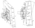
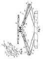
- FIG. 1is a front perspective view of an electronic display mount according to an embodiment of the invention
- FIG. 2is a front elevation view of the mount of FIG. 1 ;
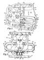
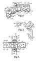
- FIG. 3is a fragmentary perspective view of an attachment channel assembly of an electronic display mount according to an embodiment of the invention.
- FIG. 4is a top plan view of the attachment channel assembly of FIG. 3 coupled with a carrier portion of a mount according to an embodiment of the invention
- FIG. 5is a rear elevation view of the attachment channel assembly and carrier portion of FIG. 4 ;
- FIG. 6is a rear perspective view of one of the attachment channels depicted in FIGS. 4 and 5 ;
- FIG. 7is a top plan view of the electronic display mount of FIG. 1 ;
- FIG. 8is a rear perspective view of the display interface portion of a mount according to an embodiment of the invention coupled with an electronic display device;
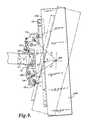
- FIG. 9is a fragmentary side elevation view of the mount and display of FIG. 8 , depicting the display being selectively tilted about a tilt axis B-B;
- FIG. 9 ais a fragmentary side elevation view of a portion of the guide member and carrier portions of a mount according to an alternative embodiment of the invention.
- FIG. 9 bis a fragmentary side elevation view of a portion of the guide member and carrier portions of a mount according to another alternative embodiment of the invention.
- FIG. 9 cis a fragmentary side elevation view of a portion of the guide member and carrier portions of a mount according to another alternative embodiment of the invention.
- FIG. 10is a fragmentary side elevation view of the mount and display of FIG. 8 with the follower member, interface plate and display depicted in phantom and with the tilt axis positioned in a first location at a first distance from the interface plate;
- FIG. 11is a fragmentary side elevation view of the mount and display of FIG. 8 with the follower member, interface plate and display depicted in phantom and with the tilt axis positioned in a second location at a second distance from the interface plate;
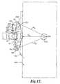
- FIG. 12is a fragmentary side elevation view of the mount and display of FIG. 8 with the follower member, interface plate and display depicted in phantom and with the tilt axis positioned in a third location at a third distance from the interface plate;
- FIG. 13is a rear perspective view of the mount of FIG. 8 with the follower member depicted in phantom to enable viewing of the upper and lower guide members;
- FIG. 13 ais a fragmentary top plan view of the mount of FIG. 8 ;
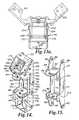
- FIG. 14is a rear perspective view of the mount of FIG. 8 without the follower member and follower pins;
- FIG. 15is a rear perspective view of the carrier portion of the mount of FIG. 8 ;
- FIG. 16is a rear perspective view of the upper guide member portion of the mount of FIG. 8 ;
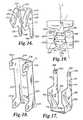
- FIG. 17is a rear perspective view of the lower guide member portion of the mount of FIG. 8 ;
- FIG. 18is a rear perspective view of the follower member portion of the mount of FIG. 8 ;
- FIG. 19is a side elevation view of a positioning tab and positioning notch taken at inset 19 of FIG. 14 ;
- FIG. 20is a rear perspective view of the display interface portion of a mount according to an alternative embodiment of the invention, coupled with an electronic display device;
- FIG. 21is a fragmentary front perspective view of the display interface portion of the mount of FIG. 20 depicted without an interface plate;
- FIG. 22is a fragmentary front perspective view of the mount of FIG. 21 depicted without an interface plate and outer carrier;
- FIG. 23is a rear perspective view of the outer carrier portion of the mount of FIG. 20 ;
- FIG. 24is a rear perspective view of the inner carrier portion of the mount of FIG. 20 ;
- FIG. 25is a rear perspective view of the upper guide member portion of the mount of FIG. 20 ;
- FIG. 26is a rear perspective view of one of the lower guide member portions of the mount of FIG. 20 ;
- FIG. 27is a fragmentary side elevation view of the mount and display of FIG. 20 with the outer carrier, interface plate and display depicted in phantom and with the tilt axis positioned in a first location at a first distance from the interface plate;
- FIG. 28is a fragmentary side elevation view of the mount and display of FIG. 20 with the outer carrier, interface plate and display depicted in phantom and with the tilt axis positioned in a second location at a second distance from the interface plate.
- Mount 30generally includes structure interface 32 , cantilever support 34 and device interface 36 .
- Structure interface 32generally includes mounting bars 38 , 39 , which attach to fixed structure 40 such as planar wall surface 42 , and upright columns 44 extending between mounting bars 38 , 39 .
- Cantilever support 34generally includes articulating arm assemblies 46 , 48 , and height adjustment mechanism 50 .
- Each articulating arm assembly 46 , 48generally includes lower arm 52 and upper arm 54 connected at pivot 56 .
- Each lower arm 52includes sleeve 58 received on one of upright columns 44 and vertically slidable thereon.
- Height adjustment, mechanism 50generally includes base portion 62 on mounting bar 39 and upper portion 64 operably coupled with sleeves 58 .
- Threaded coupler 66extends between base portion 62 and upper portion 64 and receives jacking nut 68 , which bears on the underside of upper portion 64 .
- articulating arm assembliesmay be translated together vertically by rotating jacking nut 68 up or down on threaded coupler 66 , thereby sliding upper portion 64 and sleeves 58 up or down on upright columns 44 .
- Further details of embodiments of structure interface 32 and cantilever support 34are disclosed in U.S. patent application Ser. No. 11/447,226, hereby fully incorporated herein by reference.
- Device interface 36in an embodiment depicted in FIGS. 8-18 , generally includes carrier 70 , upper guide member 72 , lower guide member 74 , follower member 76 , and interface plate 78 .
- Carrier 70generally includes back plane 79 with spaced-apart lateral flanges 80 , 82 , and spaced apart horizontal flanges 84 , 86 , projecting therefrom.
- Upper aperture 88 and lower aperture 90are defined in lateral flange 80 in registry with corresponding upper and lower apertures 88 , 90 , defined in lateral flange 82 .
- Each lateral flange 80 , 82defines a pair of facing shoulders 91 a , 91 b .
- Horizontal flange 84defines round aperture 92 and oblong aperture 94
- horizontal flange 86defines round aperture 96 in registry with aperture 92 .
- attachment channels 60 , 61generally include back wall 98 with projecting upper and lower flanges 100 , 102 , respectively.
- Apertures 104are defined in each of upper and lower flanges 100 , 102 proximate outer end 106 , each for receiving a fastener 108 to fix each attachment channel 60 , 61 , to one of upper arms 54 .
- Proximate inner end 110 , upper flange 100defines aperture 112 in registry with aperture 114 defined in lower flange 102 .
- attachment channels 60 , 61are positioned so as to overlap, with apertures 112 and 114 in registry.
- Bushing 116is received through apertures 112 and bushing 118 is received through apertures 114 .
- Bushings 116 , 118together define bore 120 , which is disposed in registry with apertures 92 , 96 , in horizontal flanges 84 , 86 of carrier 70 .
- Bolt 122is received through apertures 92 , 96 , and bore 120 , and is secured in place with nut 124 .
- Attachment channel 60is received between facing shoulders 91 a , 91 b , of lateral flange 80 with upper flange 100 confronting shoulder 91 a and lower flange 102 confronting shoulder 91 b.
- carrier 70In use, carrier 70 , and each of attachment channels 60 , 61 , and the upper arms 54 attached thereto are pivotable about bolt 122 . Accordingly, a user may push or pull on device interface 36 , which causes arms 52 , 54 , to pivot at sleeves 58 , pivot 56 and at bolt 122 .
- the articulating arrangement of arms 52 , 54 , and the pivotal connections of sleeves 58 with upright columns 44 of attachment channels 60 , 61 , with carrier 70 at bolt 122enable the device interface and a display attached thereto to be selectively positioned laterally and inward and outward relative to the fixed structure 40 .
- upper guide member 72generally includes a pair of lateral walls 126 , 128 , connected by upper wall 130 .
- Lateral wall 126defines apertures 132 , 134 , in registry with apertures 136 , 138 , respectively, defined in lateral wall 128 .
- Each lateral wall 126 , 128also defines a guide structure in the form of a slot 140 , 142 . Further, positioning tabs 144 , 146 , are defined at the bottom tips 148 , 150 , of each of lateral walls 126 , 128 respectively.
- Pivot pin 152extends through upper apertures 88 of carrier 70 and apertures 134 , 138 , of upper guide member 72 to pivotally couple upper guide member 72 to carrier 70 about pivot pin 152 .
- Adjustment carrier pin 154has an axial bore 156 with interior threads extending inward from each end 158 , 160 . Threaded fasteners 162 extend inward through apertures 132 , 136 , and thread into axial bore 156 to rotatably couple adjustment carrier pin 154 between lateral walls 126 , 128 .
- Adjustment carrier pin 154further defines transverse bore 164 with interior threading receiving adjustment screw 166 therethrough. Adjustment screw 166 extends downward through oblong aperture 94 in carrier 70 .
- Nut 168is fixed on adjustment screw 166 to prevent adjustment screw 166 from being withdrawn from oblong aperture 94 .
- adjustment screw 166when adjustment screw 166 is tightened, nut 168 will slidingly rotate against the underside 170 of horizontal flange 84 , and since nut 168 is fixed onto adjustment screw 166 , adjustment screw 166 will not vertically translate relative to carrier 70 .
- adjustment carrier pin 154As adjustment screw 166 threads into adjustment carrier pin 154 , however, adjustment carrier pin 154 is drawn closer to head 172 , causing upper guide member 72 to pivot about pivot pin 152 in a clockwise direction when viewed from the perspective of FIG. 13 .
- adjustment carrier pin 154when adjustment screw 166 is loosened, adjustment carrier pin 154 is pushed away from head 172 , causing guide member 72 to pivot about pivot pin 152 in a counterclockwise direction when viewed from the perspective of FIG. 13 .
- Lower guide member 74generally includes a pair of lateral walls 174 , 176 , connected by lower wall 178 .
- Lateral wall 174defines aperture 180 in registry with aperture 182 defined in lateral wall 176 .
- Each lateral wall 174 , 176also defines a guide structure in the form of a slot 184 , 186 .
- positioning notches 188 , 190are defined at the upper tips 192 , 194 , of each of lateral walls 174 , 176 , respectively.
- Pivot pin 196extends through lower apertures 90 of carrier 70 and apertures 180 , 182 , of lower guide member 74 to pivotally couple lower guide member 74 to carrier 70 about pivot pin 196 .
- Positioning tabs 144 , 146 , of upper guide member 72engage in positioning notches 188 , 190 , respectively, so that as upper guide member 72 pivots, lower guide member 74 pivots a corresponding distance in the opposite pivotal direction.
- FIG. 19The engagement of positioning tab 146 in positioning notch 190 in a exemplary embodiment is depicted in FIG. 19 .
- Front edge 198 of positioning tab 146is angled at angle ⁇ with respect to the longitudinal axis A-A of lateral wall 128 , while rear edge 200 may be angled at angle ⁇ , so that positioning tab 146 has a lower portion 202 presenting a first width W 1 , and an upper neck portion 204 presenting a second width W 2 smaller than first width W 1 .
- First width W 1may be only slightly smaller than the width W 3 of positioning notch 190 so that front edge 198 and rear edge 200 of positioning tab 146 smoothly engage inner periphery 206 of positioning notch 190 as upper guide structure 72 and lower guide structure 74 rotate with respect to each other.
- Second width W 2is selected so as to enable a desired range of rotation of positioning tab 146 within positioning notch 190 .
- angles ⁇ and ⁇may be different from each other where more rotational range is desired in one rotational direction.
- angle ⁇may be in a range from about 1 to about 10 degrees, while angle ⁇ is in a range from about 5 to about 20 degrees. In another embodiment angle ⁇ may be about 5 degrees while angle ⁇ is about 10 degrees.
- Follower member 76generally includes web 208 and a pair of spaced apart lateral walls 210 , 212 , defining a channel 214 .
- Web 208defines apertures 216 for receiving fasteners 218 to attach interface plate 78 on outer face 220 of web 208 .
- Lateral wall 210defines upper aperture 222 and lower aperture 224 in registry with upper aperture 226 and lower aperture 228 , respectively, defined in lateral wall 212 .
- Upper follower pin 230extends through upper apertures 222 , 226 , and slots 140 , 142 , while lower follower pin 232 extends through lower apertures 224 , 228 , and slots 184 , 186 .
- upper 230 and lower 232 follower pinsare retained in position with retainers 234 on opposing ends of the pins, facing the outer surfaces 236 , 238 , of lateral walls 210 , 212 .
- Upper and lower follower pins 230 , 232are slidable or rollable in slots 140 , 142 , and 184 , 186 , thereby enabling follower member 76 , interface plate 78 and an attached electronic display 240 or other device to tilt relative to carrier 70 and ultimately fixed structure 40 as depicted in FIG. 9 .
- slots 140 , 184 , and 142 , 186are positioned along arcs 242 of a circle centered on a generally horizontal tilt axis annotated B-B in the Figures.
- Tilt axis B-Bextends through electronic display 240 at a distance D in front of interface plate 78 , as depicted in FIG. 9 .
- Display 240may be tilted about tilt axis B-B, for example by pushing or pulling the top or bottom edge of the display 240 .
- Upper and lower follower pins 230 , 232will slide or roll in slots 140 , 142 , and 184 , 186 , and follower member 76 , interface plate 78 and the attached electronic display 240 will rotate about tilt axis B-B.
- the position of tilt axis B-Bmay be selectively adjusted with adjustment screw 166 .
- upper guide member 72 and lower guide member 74are positioned intermediate the travel limits of the mechanism.
- Slots 140 , 184 , and 142 , 186are positioned along arcs 242 of a circle having radius R 1 and centered on tilt axis B-B.
- Tilt axis B-Bis positioned at distance D 1 from interface plate 78 .
- adjustment carrier pin 154is urged away from head 172 , causing upper guide member 72 to pivot about pivot pin 152 in a counterclockwise direction when viewed from the vantage point of FIG. 12 .
- lower guide member 74is simultaneously pivoted clockwise about pivot pin 196 when viewed from the vantage point of FIG. 12 .
- the orientation of slots 140 , 184 , and 142 , 184is altered so as to define new arcs 242 having radius R 3 greater than radius R 1 .
- Tilt Axis B-Bis moved away from interface plate 78 , defining a new distance D 3 greater than distance D 1 .
- tilt axis B-Bmay be selectively positioned to coincide with or pass proximate the center of gravity C.G. of an electronic display 240 so that display 240 or other device mounted to interface plate 78 may be tilted in either rotational direction about tilt axis B-B with approximately equal effort.
- the ability to shift the location of tilt axis B-B relative to interface plate 78 according to embodiments of the inventionis particularly advantageous in that displays 240 of a variety of thicknesses and with a variety of center of gravity locations can be accommodated with the same device interface 36 .
- the location of tilt axis B-Bmay be adjusted to coincide with the center of gravity C.G.
- a relatively thicker display device or one in which the center of gravity C.G. is a different distance from interface plate 78may also be accommodated on the same mount and balanced for lower tilt effort by adjusting the location of tilt axis B-B to coincide with the center of gravity C.G. of the device 240 with adjustment screw 166 .
- multiple guide structuresare provided in the form of slots 140 , 184 , and 142 , 186 .
- the present inventionis not limited to any particular guide structure form, and that other guide structures, such as channels, grooves, ridges, or cam edges, coupled with compatible follower structures may also be used.
- the guide structuresare desirably curved to provide smooth operation for the mechanism, the guide structures may also be straight as depicted for example in FIG. 9 a , angular as depicted for example in FIG. 9 b , or any other shape capable of defining a generally arcuate path either alone or in combination with other guide structures.
- one or more of the guide structuresmay be fixed in position so long as at least one guide structure is selectively shiftable to effect shifting of the tilt axis.
- lower guide structure 74is fixed to carrier 70 with rivets 244
- upper guide structure 72is selectively pivotable about pivot pin 152 as before.
- arcs 242 of varying radiifor example R 1 , R 2 or R 3
- guide structures 140 , 184 , and 142 , 186are defined by guide structures 140 , 184 , and 142 , 186 .
- the orientation of guide structures 184 , 186remains fixed causing a general tendency of the resultant tilt axis to shift vertically as well as horizontally as depicted.
- device interface 36generally includes inner carrier 246 , upper guide structure 248 , a pair of lower guide structures 250 , outer carrier 252 , and adjustment assembly 254 .
- Inner carrier 246as depicted in FIG. 24 , generally includes back plane 256 with spaced-apart lateral flanges 258 , 260 , and spaced apart horizontal flanges 262 , 264 , projecting therefrom.
- Upper follower aperture 266 and lower follower aperture 268are defined in lateral flange 258 in registry with corresponding upper and lower follower apertures 270 , 272 , defined in lateral flange 260 .
- Each lateral flange 258 , 260defines a pair of facing shoulders 274 , 276 .
- Horizontal flange 262defines aperture 278 while horizontal flange 264 defines aperture 280 in registry with aperture 278 .
- attachment channels 60 , 61are positioned so as to overlap, with apertures 112 and 114 in registry.
- Bushing 116is received through apertures 112 and bushing 118 is received through apertures 114 .
- Bushings 116 , 118together define bore 120 , which is disposed in registry with apertures 278 , 280 , in horizontal flanges 262 , 264 , of inner carrier 246 .
- bolt 122is received through apertures 278 , 280 , and bore 120 , and is secured in place with a nut (not depicted).
- Attachment channel 60is received between facing shoulders 274 , 276 , of lateral flanges 258 , 260 , with upper flange 100 confronting shoulder 274 and lower flange 102 confronting shoulder 276 .
- inner carrier 246 , and each of attachment channels 60 , 61 , and the upper arms 54 attached theretoare pivotable about bolt 122 . Accordingly, a user may push or pull on device interface 36 , which causes arms 52 , 54 , to pivot at sleeves 58 , pivot 56 and at bolt 122 .
- the articulating arrangement of arms 52 , 54 , and the pivotal connections of sleeves 58 with upright columns 44 of attachment channels 60 , 61 , with carrier 70 at bolt 122enable the device interface and a display attached thereto to be selectively positioned laterally and inward and outward relative to the fixed structure 40 .
- upper guide member 248generally includes a pair of lateral walls 282 , 284 , connected by upper wall 286 .
- Lateral wall 282defines apertures 288 , 290 , in registry with apertures 292 , 294 , respectively, defined in lateral wall 284 .
- Each lateral wall 282 , 284also defines a guide structure in the form of a slot 296 , 298 .
- Positioning tabs 300 , 302are defined at the bottom tips 304 , 306 , of each of lateral walls 282 , 284 , respectively.
- Lower guide member 250defines aperture 308 , a guide structure in the form of slot 310 and a friction adjustment slot 312 .
- Positioning notch 314is defined at upper tip 316 .
- Outer carrier 252 as depicted in FIG. 23generally includes back portions 318 , 320 , with spaced-apart lateral flanges 322 , 324 , projecting therefrom.
- Upper pivot aperture 326 and lower pivot aperture 328are defined in lateral flange 322 in registry with corresponding upper and lower pivot apertures 330 , 332 , defined in lateral flange 324 .
- Back portions 318 , 320define apertures 334 for receiving fasteners (not depicted) to attach interface plate 78 on outer faces 336 of back portions 318 , 320 .
- Apertures 337are defined at the upper tip 339 of each lateral flange 322 , 324 .
- Upper guide member 248is pivotally coupled to outer carrier 252 between lateral flanges 322 , 324 , at pivots 338 which extend inward from the outer surface of lateral flanges 322 and 324 , through upper pivot aperture 326 and aperture 290 and upper pivot aperture 330 and aperture 294 , respectively.
- a lower guide member 250is pivotally coupled on the inside face 340 of each lateral flange 322 , 324 , at pivots 342 , which extend inward from the outer surface of lateral flanges 322 and 324 , through lower pivot apertures 328 and into aperture 308 .
- each lower guide member 250is engaged with one of positioning tabs 300 , 302 , of upper guide member 248 as before so that as upper guide member 248 pivots, lower guide members 250 pivot in unison a corresponding distance in the opposite pivotal direction.
- Follower pins 344 , 346are received through apertures 266 , 270 , and 268 , 272 , of inner carrier 246 , respectively.
- Inner carrier 246is received between lateral flanges 282 , 284 of upper guide member 248 and between lower guide members 250 .
- Follower pin 344presents opposing ends 348 , 350 , which are slidably or rollably engaged in guide structures 296 , 298 , of upper guide member 248 respectively.
- follower pin 346presents opposing ends 352 , 354 , which are slidably or rollably engaged in guide structures 310 of the separate lower guide members 250 .
- Adjustment assembly 254generally includes carrier 356 , adjustment screw 358 , and pivot block 360 .
- Carrier 356generally includes an L-shaped body portion 362 with a pair of opposing lateral ears 364 .
- Body portion 362is pivotally coupled between lateral flanges 322 , 324 , of outer carrier 252 with pivots 366 extending through apertures 337 into ears 364 .
- Adjustment screw 358has threaded shaft portion 367 extending through front wall 368 of body portion 362 .
- Retainer 369 and knob 370 on either side of front wall 368retain and prevent translation of adjustment screw 358 relative to body portion 362 .
- Pivot block 360is pivotally coupled between lateral flanges 282 , 284 , of upper guide member 248 with pivots 372 extending through apertures 288 and 292 and into pivot block 360 .
- Pivot block 360further defines transverse threaded aperture 374 which receives threaded shaft portion 367 of adjustment screw 358 .
- pivot block 360In use, as adjustment screw 358 is tightened, pivot block 360 is drawn toward front wall 368 , causing upper guide member 248 to pivot about pivots 338 in a clockwise direction when viewed from the vantage point of FIGS. 27 and 28 . Due to the engagement of positioning tabs 300 , 302 , in positioning notches 312 , lower guide members 250 are simultaneously pivoted counterclockwise about pivots 342 when viewed from the vantage point of FIGS. 27 and 28 . As a result of the pivoting motion of upper guide member 248 and lower guide members 250 , the orientation of slots 296 , 298 , and 310 is altered so as to define new arcs 242 having a relatively larger radius R. Tilt Axis B-B is moved away from interface plate 78 , so that distance D is relatively larger.
- pivot block 360is urged away from front wall 368 , causing upper guide member 248 to pivot about pivots 338 in a counterclockwise direction when viewed from the vantage point of FIGS. 27 and 28 .
- lower guide members 250are simultaneously pivoted clockwise about pivots 342 when viewed from the vantage point of FIGS. 27 and 28 .
- the orientation of slots 296 , 298 , and 310is altered so as to define new arcs 242 having a relatively smaller radius R.
- Tilt Axis B-Bis toward from interface plate 78 , so that distance D is relatively smaller.
- a display 240 or other device coupled to interface plate 78may be tilted about tilt axis B-B, for example by pushing or pulling the top or bottom edge of the display 240 .
- Follower pins 344 , 346will slide or roll in slots 296 , 298 and 310 , and outer carrier 252 , upper guide member 248 , lower guide members 250 , interface plate 78 and the attached electronic display 240 will rotate about tilt axis B-B.
Landscapes
- Engineering & Computer Science (AREA)
- General Engineering & Computer Science (AREA)
- Mechanical Engineering (AREA)
- Devices For Indicating Variable Information By Combining Individual Elements (AREA)
Abstract
Description
Claims (21)
Priority Applications (1)
| Application Number | Priority Date | Filing Date | Title |
|---|---|---|---|
| US12/522,142US8072739B2 (en) | 2007-01-03 | 2008-01-03 | Device mount with selectively positionable tilt axis |
Applications Claiming Priority (3)
| Application Number | Priority Date | Filing Date | Title |
|---|---|---|---|
| US88330307P | 2007-01-03 | 2007-01-03 | |
| US12/522,142US8072739B2 (en) | 2007-01-03 | 2008-01-03 | Device mount with selectively positionable tilt axis |
| PCT/US2008/000044WO2008083396A1 (en) | 2007-01-03 | 2008-01-03 | Device mount with selectively positionable tilt axis |
Publications (2)
| Publication Number | Publication Date |
|---|---|
| US20100091438A1 US20100091438A1 (en) | 2010-04-15 |
| US8072739B2true US8072739B2 (en) | 2011-12-06 |
Family
ID=39589014
Family Applications (1)
| Application Number | Title | Priority Date | Filing Date |
|---|---|---|---|
| US12/522,142ActiveUS8072739B2 (en) | 2007-01-03 | 2008-01-03 | Device mount with selectively positionable tilt axis |
Country Status (5)
| Country | Link |
|---|---|
| US (1) | US8072739B2 (en) |
| EP (1) | EP2108180B1 (en) |
| CN (1) | CN101720482B (en) |
| CA (1) | CA2674471C (en) |
| WO (1) | WO2008083396A1 (en) |
Cited By (20)
| Publication number | Priority date | Publication date | Assignee | Title |
|---|---|---|---|---|
| US20120032062A1 (en)* | 2010-08-04 | 2012-02-09 | Brian Newville | Television mount assembly |
| US20130327911A1 (en)* | 2010-02-22 | 2013-12-12 | 3D Space Arms Pty Ltd | Support Mechanism |
| US20140034793A1 (en)* | 2009-01-05 | 2014-02-06 | Peerless Industries, Inc. | Low Profile Mounting System |
| US8675354B2 (en)* | 2007-06-27 | 2014-03-18 | Voxx International Corporation | Multi-media memo board |
| US20150050071A1 (en)* | 2012-04-09 | 2015-02-19 | Illinois Tool Works Inc. | Arcuate clip assembly |
| US9052057B2 (en) | 2012-10-02 | 2015-06-09 | Mw Products Llc | Flexible mount apparatus and system |
| AU2015224380B2 (en)* | 2011-02-22 | 2017-02-02 | 3D Space Arms Pty Ltd | A Support Mechanism |
| US10081955B2 (en)* | 2015-07-24 | 2018-09-25 | Zipwall, Llc. | Partition mount system including head coupler with adjustable head length and head position |
| US10154729B2 (en) | 2016-05-10 | 2018-12-18 | Knape & Vogt Manufacturing Company | Articulating ergonomic support arm |
| US10646033B2 (en) | 2018-03-02 | 2020-05-12 | Ergotron, Inc. | Height adjustable platforms and associated mechanisms |
| US10781597B2 (en) | 2015-12-28 | 2020-09-22 | Zipwall, Llc | Self-closing entryway partition |
| US11071377B2 (en) | 2018-03-02 | 2021-07-27 | Ergotron, Inc. | Height adjustable platforms and associated mechanisms |
| US11112057B2 (en) | 2019-07-10 | 2021-09-07 | Ergotron, Inc. | Display mounting system and method |
| USD1002351S1 (en) | 2019-04-25 | 2023-10-24 | Legrand Av Inc. | Tapered articulating arm assembly for wall-mounted display mount |
| US11933450B2 (en) | 2021-05-12 | 2024-03-19 | Colebrook Bosson & Saunders (Products) Limited | Tilt head for high load display support system |
| US20240218960A1 (en)* | 2022-12-29 | 2024-07-04 | Shenzhen Bestqi Innovation Technology Co., Ltd. | Spring-balanced vertical-tilt mechanism for display mount |
| US20240218962A1 (en)* | 2022-12-29 | 2024-07-04 | Shenzhen Bestqi Innovation Technology Co., Ltd. | Vertical-tilt mechanism for display mount with eccentric gear |
| USD1036703S1 (en) | 2021-11-17 | 2024-07-23 | Zipwall, Llc | Door panel with window |
| US20240271744A1 (en)* | 2023-02-15 | 2024-08-15 | Weiping Cai | Adjustment component and multi-functional tv bracket |
| US12098589B2 (en) | 2018-12-06 | 2024-09-24 | Zipwall, Llc | Self-closing entryway for door-frame |
Families Citing this family (27)
| Publication number | Priority date | Publication date | Assignee | Title |
|---|---|---|---|---|
| AU2008205387A1 (en) | 2007-01-05 | 2008-07-17 | Milestone Av Technologies Llc | Wall-avoiding self-balancing mount for tilt positioning of a flat panel electronic display |
| PL384694A1 (en)* | 2008-03-14 | 2009-09-28 | Furniture In Motion, Inc. | Display screen head, especially of a flat television screen |
| TW201028585A (en) | 2009-01-05 | 2010-08-01 | Peerless Ind Inc | Moveable mounting system |
| TW201030266A (en)* | 2009-01-05 | 2010-08-16 | Peerless Ind Inc | Multiple arm articulating mounting system |
| US8891249B2 (en) | 2009-01-07 | 2014-11-18 | Milestone Av Technologies Llc | Display mount with adjustable position tilt axis |
| US10281080B1 (en) | 2010-06-04 | 2019-05-07 | Kurt William Massey | Adjustable mounting systems for televisions |
| US8724037B1 (en) | 2010-06-04 | 2014-05-13 | Kurt William Massey | Mounting system |
| US9625091B1 (en) | 2014-12-06 | 2017-04-18 | Kurt William Massey | Adjustable mounting systems for televisions |
| CN103460689A (en) | 2010-11-30 | 2013-12-18 | 麦尔斯顿Av技术有限责任公司 | Electronic display mount with extreme tilt feature |
| US9062816B2 (en) | 2012-01-06 | 2015-06-23 | Wirepath Home Systems, Llc | Tilt head assemblies and methods of using the same |
| CN102887382B (en)* | 2012-10-19 | 2016-01-20 | 江苏高博智融科技有限公司 | A kind of pushing plate |
| CN104885447B (en)* | 2012-11-05 | 2018-07-31 | 里程碑影音技术有限责任公司 | Short focus projector bracket with fine tuning structure |
| US9383060B2 (en)* | 2012-12-06 | 2016-07-05 | Synergy Global Supply, Inc. | Security wall rack and television mount combination |
| CN103915040B (en)* | 2013-01-07 | 2018-09-11 | 三星电子株式会社 | display screen |
| CA2926679C (en)* | 2013-10-09 | 2022-04-12 | Milestone Av Technologies Llc | Cleat mount with visual and audible indicator |
| USD743969S1 (en) | 2013-10-16 | 2015-11-24 | Wirepath Home Systems, Llc | Single arm articulating mount for an electronic display |
| USD747724S1 (en) | 2013-12-20 | 2016-01-19 | Wirepath Home Systems, Llc | Dual arm articulating mount for an electronic display |
| US9699924B2 (en)* | 2014-08-26 | 2017-07-04 | Milestone Av Technologies Llc | Display mount leveler |
| US12152720B1 (en) | 2017-04-17 | 2024-11-26 | Manehu Product Alliance, Llc | Adjustable mounting systems for televisions |
| US10738941B2 (en) | 2017-09-04 | 2020-08-11 | Manehu Product Alliance, Llc | Display mount assembly |
| US10859201B2 (en) | 2018-04-10 | 2020-12-08 | Manehu Product Alliance, Llc | Display mount assembly |
| CN110388548B (en)* | 2018-04-19 | 2022-04-22 | 鸿富锦精密电子(重庆)有限公司 | Display device |
| US11215313B1 (en)* | 2019-05-24 | 2022-01-04 | Snap One, Llc | Display mounts and related systems and methods |
| US11033107B2 (en) | 2019-07-16 | 2021-06-15 | Francis Douglas Warren | Tilting mounting apparatus |
| WO2021127552A1 (en) | 2019-12-19 | 2021-06-24 | Manehu Product Alliance, Llc, D/B/A | Adjustable display mounting system |
| WO2021159112A1 (en) | 2020-02-08 | 2021-08-12 | MANEHU PRODUCT ALLIANCE, LLC, d/b/a MANTELMOUNT | Display mounting system with adjustable weight counterbalance |
| US11287080B2 (en) | 2020-02-10 | 2022-03-29 | Manehu Product Alliance, Llc | Multidirectional display mount |
Citations (204)
| Publication number | Priority date | Publication date | Assignee | Title |
|---|---|---|---|---|
| US153943A (en) | 1874-08-11 | Improvement in brackets for dentists chairs | ||
| US212618A (en) | 1879-02-25 | Improvement in doors for stoves | ||
| US257050A (en) | 1882-04-25 | La mp-bracket | ||
| US1282489A (en) | 1916-02-08 | 1918-10-22 | Frank A Strodel | Drawing-board holder. |
| US1320775A (en) | 1919-11-04 | Lamp-stjppobt | ||
| US1358159A (en) | 1920-03-09 | 1920-11-09 | Kern John | Reflector-mounting |
| US1574277A (en) | 1924-10-14 | 1926-02-23 | Henry M Groue | Rim and tire construction for vehicle wheels |
| US1628218A (en) | 1926-02-09 | 1927-05-10 | Dora F Beauchamp | Adjustable reflector |
| US1646379A (en) | 1924-12-22 | 1927-10-18 | Kales Stamping Company | Mirror support |
| US1977153A (en) | 1928-05-23 | 1934-10-16 | Remac Patents Corp | Mount for moving picture cameras |
| US2030889A (en) | 1933-04-01 | 1936-02-18 | Sidney H Negrotto | Mount for machine guns |
| US2233882A (en) | 1938-01-24 | 1941-03-04 | Bobek William | Self-locking concealed hinge |
| US2466219A (en) | 1944-03-31 | 1949-04-05 | Sydney T Farrell | Gun mount |
| US2525534A (en) | 1947-11-05 | 1950-10-10 | Eastman Kodak Co | Elevating mechanism |
| US2734708A (en) | 1956-02-14 | Mounting of antenna masts | ||
| US2967035A (en) | 1957-09-23 | 1961-01-03 | Elizabeth W Simons | Hinge mounting for mirrors and the like |
| US3182946A (en) | 1963-01-23 | 1965-05-11 | Dudko Nicholas | Swing-away can opener |
| GB994246A (en) | 1963-02-25 | 1965-06-02 | Maurice Prentice Burke | Tilt swivel mechanism for chairs |
| US3574340A (en) | 1969-02-27 | 1971-04-13 | Kenneth A Busche | Television receiver adjustable tilt suspension |
| GB1280913A (en) | 1970-07-06 | 1972-07-12 | Rank Organisation Ltd | Motion picture camera mounts |
| US4068961A (en) | 1976-08-23 | 1978-01-17 | Milgo Electronic Corporation | Swivel joint |
| US4238802A (en) | 1978-12-18 | 1980-12-09 | General Dynamics Corporation, Pomona Division | Differential drive rolling arc gimbal |
| DE3215379A1 (en) | 1982-04-24 | 1983-10-27 | Plaubel, Feinmechanik & Optik GmbH, 6000 Frankfurt | Photographic camera provided for groundglass focusing |
| US4483803A (en) | 1982-09-30 | 1984-11-20 | The Halcon Sd Group, Inc. | Preparation of carboxylic acid anhydrides |
| US4483503A (en) | 1981-04-03 | 1984-11-20 | Mouldmaking Design Centre Limited | Swivel mountings |
| US4549710A (en) | 1982-02-26 | 1985-10-29 | Plessey Overseas Limited | Supporting assembly |
| US4554590A (en) | 1980-06-05 | 1985-11-19 | Ing. C. Olivetti & C., S.P.A. | Device for positioning video display unit |
| US4562988A (en) | 1984-06-27 | 1986-01-07 | Northern Telecom Limited | Video display mounting mechanism providing pivoting and tilting of the display |
| US4621782A (en) | 1984-07-26 | 1986-11-11 | At&T Bell Laboratories | Arrangement for mounting apparatus |
| US4645153A (en) | 1985-05-23 | 1987-02-24 | Ncr Corporation | Tilt and swivel support |
| US4652890A (en) | 1984-07-24 | 1987-03-24 | Crean Robert F | High rigidity, low center of gravity polar mount for dish type antenna |
| US4687305A (en) | 1984-05-29 | 1987-08-18 | Spy-Mirrors, Inc. | Mirror mounting apparatus |
| US4708312A (en) | 1985-10-23 | 1987-11-24 | Ncr Corporation | Extensible height-adjustable swivel arm for supporting a display or the like |
| US4718317A (en) | 1986-08-21 | 1988-01-12 | Roy F. Hensler | Hose coupling wrench |
| US4762378A (en) | 1986-03-17 | 1988-08-09 | Sanyo Electric Co., Ltd. | Display apparatus |
| US4768744A (en) | 1986-08-27 | 1988-09-06 | Richard Leeds | Apparatus for supporting a load in a dynamically balanced condition |
| US4814759A (en) | 1987-07-08 | 1989-03-21 | Clinicom Incorporated | Flat panel display monitor apparatus |
| US4836486A (en) | 1987-04-16 | 1989-06-06 | Anthro Corporation | Adjustable support |
| US4836478A (en) | 1987-10-15 | 1989-06-06 | Ergotron, Inc. | Suspension system for personal computers and monitors |
| US4844387A (en) | 1986-12-31 | 1989-07-04 | Hunt Holdings, Inc. | Monitor arm apparatus |
| US4880191A (en) | 1984-07-05 | 1989-11-14 | Unisys Corporation | Mounting arrangement for display terminal |
| US4934645A (en) | 1989-03-20 | 1990-06-19 | Rtc Industries, Inc. | Shelving assembly |
| US4989813A (en) | 1989-11-29 | 1991-02-05 | Samsung Electron Devices Co., Ltd. | Supporting base for controlling height, swivel and inclination of display means |
| US5037050A (en) | 1990-03-28 | 1991-08-06 | Digital Equipment Corporation | Interlocking assembly for adjustable mounting of a display unit |
| US5040759A (en) | 1990-07-05 | 1991-08-20 | Wainwright Andrew G | Camera mount for taking panoramic pictures |
| US5102081A (en) | 1991-03-15 | 1992-04-07 | Barchus David D | Telescopable pivotal mounting assembly |
| US5102082A (en) | 1989-11-30 | 1992-04-07 | Hyundai Electronics Ind. Co., Ltd. | Tiltable and rotatable base for a monitor |
| US5139223A (en) | 1991-04-09 | 1992-08-18 | Marty Sedighzadeh | Wall/ceiling support for television monitor |
| US5165644A (en) | 1991-07-25 | 1992-11-24 | Thomas Allen | Mounting apparatus for a video display |
| US5195900A (en) | 1990-10-02 | 1993-03-23 | Yazaki Corporation | Adjustable position connector mounting structure |
| US5209446A (en) | 1991-02-18 | 1993-05-11 | Mitsubishi Denki Kabushiki Kaisha | Rotary stand |
| US5277392A (en) | 1992-10-19 | 1994-01-11 | Curtis Manufacturing Company, Inc. | Adjustable computer monitor arm and method |
| US5305114A (en) | 1991-07-12 | 1994-04-19 | Matsushita Electric Industrial Co., Ltd. | Electronic blackboard apparatus |
| US5322255A (en) | 1991-03-23 | 1994-06-21 | International Business Machines Corporation | Mounting bracket |
| US5398901A (en) | 1992-10-10 | 1995-03-21 | Haropa Products Limited | Support apparatus |
| US5404182A (en) | 1993-10-28 | 1995-04-04 | Nippon Control Industrial Co., Ltd. | Swivel chassis |
| USD361062S (en) | 1993-03-17 | 1995-08-08 | Kabushiki Kaisha Toshiba | Electronic computer |
| USD361068S (en) | 1994-04-25 | 1995-08-08 | Pacific Monolithics, Inc. | Adjustable-angle antenna-mounting bracket assembly |
| US5465557A (en) | 1994-06-09 | 1995-11-14 | Koch Supplies, Inc. | Hinge assembly for vacuum packaging machine |
| US5520361A (en) | 1993-04-20 | 1996-05-28 | Inkel Corporation | Monitor tilting device |
| US5553820A (en) | 1994-10-17 | 1996-09-10 | Rubbermaid Office Products Inc. | Adjustable monitor arm |
| US5582375A (en) | 1992-04-20 | 1996-12-10 | Martin; Michael | Adjustable ergonomic support for computer keyboards |
| US5584735A (en) | 1996-01-24 | 1996-12-17 | Mcmath; John W. | Warm water supply system |
| US5603478A (en) | 1995-08-14 | 1997-02-18 | Wang; Daniel | Keyboard support |
| US5632463A (en) | 1994-06-13 | 1997-05-27 | Samsung Electronics Co., Ltd. | Monitor stand assembly |
| US5634622A (en) | 1995-09-18 | 1997-06-03 | Pye; Craig D. | Remote controllable television viewing stand |
| US5664752A (en) | 1993-04-21 | 1997-09-09 | Vm Acoustics Aps | Direction adjustable mounting fittings |
| US5687939A (en) | 1996-04-26 | 1997-11-18 | Moscovitch; Jerry | Dual display system |
| US5687944A (en) | 1994-08-06 | 1997-11-18 | Lg Electronics, Inc. | Angle controller for image display |
| US5713549A (en) | 1995-05-22 | 1998-02-03 | Shieh; En-Ru | Monitor support device |
| US5732922A (en) | 1995-01-16 | 1998-03-31 | Lg Electronics Inc. | Monitor support |
| US5743503A (en) | 1996-03-08 | 1998-04-28 | Ergotron, Inc. | Computer suspension system |
| US5751548A (en) | 1996-05-13 | 1998-05-12 | International Business Machines Corporation | Docking station for a portable computer providing rotational movement of the computer's viewable screen in three different planes |
| US5768648A (en) | 1997-09-05 | 1998-06-16 | Roy Isaia | Camera mount for controlled and steady rolling movement |
| USD395892S (en) | 1997-05-01 | 1998-07-07 | Allen Solomon | Universal speaker mounting device |
| DE29809300U1 (en) | 1998-05-22 | 1998-08-06 | Seisler & Co., 58507 Lüdenscheid | Arrangement of a mirror |
| US5793503A (en) | 1992-01-03 | 1998-08-11 | Simian Company, Inc. | Methods of hologram construction using computer-processed objects |
| US5797568A (en) | 1996-05-30 | 1998-08-25 | Telefonica De Espana S.A. | Multi-position television monitor stand |
| US5842672A (en) | 1996-06-07 | 1998-12-01 | Ergotron, Inc. | Mounting system for flat panel display, keyboard and stand |
| US5854735A (en) | 1996-11-16 | 1998-12-29 | Adi Corporation | Device for tiltably supporting a LCD |
| US5876008A (en) | 1995-01-17 | 1999-03-02 | Ergotron, Inc. | Suspension system for video monitor or other equipment |
| US5918845A (en) | 1995-02-24 | 1999-07-06 | Commercial Brains Limited | Support brackets |
| US5923528A (en) | 1997-05-07 | 1999-07-13 | Amtran Technology Co., Ltd. | Pitvotal apparatus for flat display panel |
| US5923852A (en) | 1996-09-04 | 1999-07-13 | Advanced Micro Devices, Inc. | Method and system for fast data transmissions in a processing system utilizing interrupts |
| US5941493A (en) | 1996-11-16 | 1999-08-24 | Adi Corporation | LCD support system |
| USD415768S (en) | 1996-04-10 | 1999-10-26 | Howell Richard J | Holder for flat screen monitors |
| US6000560A (en) | 1998-02-11 | 1999-12-14 | Barkan; Lior | Support tray tilt mechanism |
| US6012693A (en) | 1998-02-19 | 2000-01-11 | Ergotron, Inc. | Multi-function display mounting system |
| US6036337A (en) | 1998-05-22 | 2000-03-14 | Belfer; Bruce D. | Virtual axis lighting fixture |
| US6042068A (en) | 1997-09-04 | 2000-03-28 | Peerless Indsutries, Inc. | Low profile LCD projector mount |
| US6045103A (en) | 1998-07-17 | 2000-04-04 | Lucent Technologies, Inc. | Multiple axis bracket with keyed mount |
| US6048013A (en) | 1996-10-07 | 2000-04-11 | Phd, Inc. | Modular stamped parts transfer gripper |
| US6047939A (en) | 1997-07-09 | 2000-04-11 | Lg Electronics Inc. | Adjustable support structure for video appliance |
| US6068227A (en) | 1997-03-11 | 2000-05-30 | Pixelvision Technology, Inc. | Flat panel display housing |
| US6086034A (en) | 1996-02-28 | 2000-07-11 | Knoll, Inc. | Independently adjustable mouse pad |
| JP2000214787A (en) | 1999-01-25 | 2000-08-04 | Toshiba Tec Corp | Display tilt mechanism |
| US6102348A (en) | 1999-04-19 | 2000-08-15 | Lucasey Manufacturing Company | Appliance mounting device |
| US6113047A (en) | 1997-12-15 | 2000-09-05 | Intermec Technologies Corporation | Dual point vehicle mount for computer terminal |
| US6119997A (en) | 1995-02-17 | 2000-09-19 | Vogel's Holding B.V. | Assembly suitable for supporting an electronic appliance, as well as a coupling piece |
| US6125030A (en) | 1998-08-07 | 2000-09-26 | Lear Donnelly Overhead Systems L.L.C. | Vehicle overhead console with flip down navigation unit |
| US6126128A (en) | 1998-11-20 | 2000-10-03 | Lucent Technologies Inc. | Adjustable mounting bracket |
| US6138970A (en) | 1999-05-07 | 2000-10-31 | Sohrt; Thomas M. | Universally adjustable mounting system |
| WO2000073697A1 (en) | 1999-05-26 | 2000-12-07 | Bang & Olufsen A/S | Support arrangement for a display device |
| US6189842B1 (en) | 1999-06-21 | 2001-02-20 | Palo Alto Design Group | Tilt and swivel adjustment of flat panel display having detents for landscape and portrait positions and kickout for preventing contact between flat panel display and base |
| US6189850B1 (en) | 1997-08-09 | 2001-02-20 | Mitac International Corp. | Rotatable LCD screen device |
| US6213821B1 (en) | 1998-09-30 | 2001-04-10 | Johnson Outdoors Inc | Trolling motor assembly |
| US6213438B1 (en) | 1999-12-16 | 2001-04-10 | Ostby Leroy M. | Computer support for vehicle use having multiple position adjustments |
| USD440863S1 (en) | 1999-03-13 | 2001-04-24 | Avf Group Limited | Bracket, principally for supporting a television set |
| JP2001142408A (en) | 1999-11-17 | 2001-05-25 | Hitachi Ltd | Image display device |
| US6244552B1 (en) | 1999-04-21 | 2001-06-12 | Force 10 Marine Ltd. | Mounting bracket for maintaining an article level |
| JP2001175188A (en) | 1999-12-20 | 2001-06-29 | Fujitsu General Ltd | Display device installation device |
| JP3078557U (en) | 2000-12-25 | 2001-07-10 | 株式会社寺岡精工 | Touch panel support structure |
| US6264152B1 (en) | 1998-07-17 | 2001-07-24 | Lucent Technologies Inc. | Multiple access mounting bracket |
| US6273382B1 (en) | 1999-09-30 | 2001-08-14 | Gregory L. Pemberton | Adjustable tilt-down keyboard support device |
| US6273383B1 (en) | 1999-09-27 | 2001-08-14 | Innovative Office Products, Inc. | Arm apparatus for mounting electronic devices, and method of making and using the same |
| US6292981B1 (en) | 1999-04-14 | 2001-09-25 | Southco, Inc. | Crescent hinge |
| US20010050327A1 (en) | 1999-11-02 | 2001-12-13 | Schwegman, Lundberg, Woessner & Kluth, P.A. | Ratcheted pivot |
| US6336037B1 (en) | 1998-03-19 | 2002-01-01 | Kabushiki Kaisha Toshiba | Portable radio terminal device |
| US6340146B1 (en) | 2000-07-28 | 2002-01-22 | Proton Electronic Industrial Co., Ltd. | Ceiling LCD mounting structure |
| US20020011544A1 (en) | 2000-03-30 | 2002-01-31 | Bosson Peter Thomas | Display device support system |
| US6347776B1 (en) | 2000-06-30 | 2002-02-19 | Po-An Chuang | Multi-directional mounting bracket |
| US20020033436A1 (en) | 2000-09-20 | 2002-03-21 | Acer Communications And Multimedia Inc. | Wall Mount unit for plasma display panel |
| US6361012B1 (en) | 2000-07-06 | 2002-03-26 | Punch Video Inc. | Television stand for a vehicle |
| US6367756B1 (en) | 2000-07-07 | 2002-04-09 | James Wang | Adjustable device support and anchor means arrangement |
| US6378171B1 (en) | 1999-02-26 | 2002-04-30 | Katoh Electrical Machinery Co., Ltd. | Tilting hinge |
| US6378830B1 (en) | 2000-10-05 | 2002-04-30 | Lu Sheng-Nan | Adjustable support for an LCD monitor |
| US6394403B1 (en) | 2000-10-26 | 2002-05-28 | Ray Hung | Supporting device for a liquid crystal display |
| WO2002042681A1 (en) | 2000-11-21 | 2002-05-30 | Eyegonomic Aps | A support for an interface unit such as a display unit or a keyboard for a computer and an arm for such a unit |
| US6402109B1 (en) | 2001-05-16 | 2002-06-11 | Chief Manufacturing, Inc. | Self-balancing mounting system for a flat panel display |
| US6409134B1 (en) | 1999-06-07 | 2002-06-25 | Innovative Office Products, Inc. | Arm apparatus for mounting electronic devices with cable management system |
| US6409127B1 (en) | 1998-10-27 | 2002-06-25 | Knape & Vogt Manufacturing Co. | Adjustable keyboard support mechanism |
| US20020084396A1 (en) | 2000-12-29 | 2002-07-04 | Weaver Timothy H. | Mounting bracket |
| US6416027B1 (en) | 2001-02-28 | 2002-07-09 | James K. Hart | Apparatus for retracting a television to a stored position and extending the television to a viewing position |
| US6418010B1 (en) | 2000-08-11 | 2002-07-09 | Gateway, Inc. | Convertible flat panel display hanging support |
| USD460078S1 (en) | 2000-12-18 | 2002-07-09 | Chin-Chu Li | Supporting frame |
| US6450467B2 (en) | 1998-10-14 | 2002-09-17 | Work-Rite Ergonomic Accessories, Inc. | Tilt adjustable keyboard support |
| US6454234B1 (en) | 2001-11-14 | 2002-09-24 | Charles Westbrook | Apparatus for supporting and restraining electronic viewing monitors without penetrating fasteners |
| US6453509B1 (en) | 2001-02-19 | 2002-09-24 | Samsung Electronics Co., Ltd. | Hinge arrangement for a display apparatus |
| US6478275B1 (en) | 2001-08-31 | 2002-11-12 | Min Hwa Huang | Support device for monitor, displayer or other object |
| US6487274B2 (en) | 2001-01-29 | 2002-11-26 | Siemens Medical Solutions Usa, Inc. | X-ray target assembly and radiation therapy systems and methods |
| US20020179801A1 (en) | 2001-06-05 | 2002-12-05 | Lg Electronics Inc. | Grade control apparatus of display set for tapestry |
| US20020179791A1 (en) | 2001-06-05 | 2002-12-05 | Lg Electronics Inc. | Apparatus for adjusting an angle of a display means and a connection bracket thereof |
| US6494429B2 (en) | 1997-08-04 | 2002-12-17 | Canon Kabushiki Kaisha | Panel support structure, display panel supported by panel support structure, and image forming apparatus using display panel |
| US20020190180A1 (en) | 2001-06-15 | 2002-12-19 | Cotterill Michael John | Linkage mechanism |
| US6505988B1 (en) | 1999-06-02 | 2003-01-14 | Innovative Office Products, Inc. | Tilter for positioning electronic devices |
| US6510049B2 (en) | 2000-01-06 | 2003-01-21 | Rosen Products Llc | Adjustable display monitor unit |
| US6517040B1 (en) | 2001-12-20 | 2003-02-11 | Mitac International Corp. | Support unit for a display device |
| US20030042385A1 (en) | 2001-08-30 | 2003-03-06 | Hannstar Display Corp. | Liquid crystal display with a ball-and-socket mounting joint |
| US6530546B1 (en) | 2000-04-25 | 2003-03-11 | Omnimount Systems, Inc. | Cable mount |
| US6543734B2 (en) | 2000-12-01 | 2003-04-08 | Acer Inc. | Flat panel display apparatus and mounting apparatus therein |
| US20030075653A1 (en) | 2001-10-19 | 2003-04-24 | Chin-Chu Li | Liquid crystal display support |
| US6554238B1 (en) | 1999-11-18 | 2003-04-29 | Claiteal Pty. Limited | Support arm for visual display unit |
| US6560094B2 (en) | 2001-03-21 | 2003-05-06 | Acme Portable Machines Gmbh | Mounting device for a monitor, a flat monitor with such a mounting device, and an assembly of a flat monitor, a drawer and a computer |
| US6559829B1 (en) | 1998-07-09 | 2003-05-06 | Mitsubishi Denki Kabushiki Kaisha | Flat display device and fixing member for display unit |
| US6565056B2 (en) | 2001-08-28 | 2003-05-20 | Chin-Chih Lin | Axial urging mechanism |
| US6575419B1 (en) | 2002-03-12 | 2003-06-10 | Sun Microsystems, Inc. | Universal support system for displays |
| US6585203B1 (en) | 2000-07-17 | 2003-07-01 | Agilent Technologies, Inc. | Flat panel display exterior rack mount |
| US6594143B2 (en) | 1998-12-11 | 2003-07-15 | Nec Corporation | Liquid crystal module mounting structure and mobile terminal mounted with the same |
| US6592090B1 (en) | 2002-08-23 | 2003-07-15 | Chin-Chu Li | Object supporting structure |
| USD477606S1 (en) | 2002-04-24 | 2003-07-22 | Ergotron, Inc. | Support for flat panel monitor display unit |
| US20030136888A1 (en) | 2002-01-23 | 2003-07-24 | Vogel's Holding B.V. | Device for tiltable mounting of a display screen on a wall |
| US6604722B1 (en) | 2002-06-10 | 2003-08-12 | Seng-Ling Tan | Display support |
| US20030154673A1 (en) | 2002-02-15 | 2003-08-21 | Macgregor Bruce G. | Partition panel with modular appliance mounting arrangement |
| US20030201372A1 (en) | 2002-04-26 | 2003-10-30 | Leonard Dozier | Mounting device for a flat screen display panel |
| US6654235B2 (en) | 2000-01-25 | 2003-11-25 | Bruce Imsand | Portable workstation computer |
| US20030227739A1 (en) | 2002-06-07 | 2003-12-11 | Samsung Electronics Co., Ltd. | Tilting and shielding apparatus of monitor |
| US6663064B1 (en) | 1999-12-01 | 2003-12-16 | Garmin Corporation | Multi-position articulating mounting apparatus for an electronic device |
| US6671928B2 (en) | 2001-05-23 | 2004-01-06 | Kuo-Cheng Huang | Hinge assembly for monitor |
| US6672553B1 (en) | 2002-08-26 | 2004-01-06 | Chin-Chih Lin | Suspension arm |
| US20040011932A1 (en) | 2002-06-07 | 2004-01-22 | Simon Duff | Stand for flat panel display |
| US20040011938A1 (en) | 2002-04-24 | 2004-01-22 | Innovative Office Products, Inc. | Multiple electronic device reorienting support |
| US6695270B1 (en) | 2002-08-15 | 2004-02-24 | Ole Falk Smed | Flat panel display system |
| US20040056161A1 (en) | 2001-12-13 | 2004-03-25 | Takashi Ishizaki | Elevation regulator of display |
| US20040079849A1 (en) | 2001-03-12 | 2004-04-29 | Alain Rudolf | Support device for a liquid crystal flat screen |
| USD493800S1 (en) | 2004-01-02 | 2004-08-03 | Decade Industries, Inc. | Display mount |
| USD494596S1 (en) | 2004-01-02 | 2004-08-17 | Decade Industries, Inc. | Display mount |
| WO2004070257A1 (en) | 2003-02-03 | 2004-08-19 | Bang & Olufsen A/S | Tilt mechanism |
| USD494978S1 (en) | 2004-01-02 | 2004-08-24 | Decade Industries, Inc. | Display mount |
| USD495713S1 (en) | 2004-01-02 | 2004-09-07 | Decade Industries, Inc. | Display mount |
| US20040211870A1 (en) | 2003-04-11 | 2004-10-28 | Jeff Bremmon | Universal mount bracket |
| US20040232301A1 (en) | 2003-04-11 | 2004-11-25 | Jeff Bremmon | Adaptable mounting system for flat panel display |
| US20040232298A1 (en) | 2003-04-11 | 2004-11-25 | Jeff Bremmon | Flat panel display mounting system |
| US20040245420A1 (en) | 2003-01-09 | 2004-12-09 | Decade Industries, Inc. | Adjustable tilt mount |
| US20050051688A1 (en) | 2003-07-23 | 2005-03-10 | Jay Dittmer | Under-cabinet mount for flat-panel displays |
| US6874743B2 (en) | 2001-12-13 | 2005-04-05 | Murakami Corporation | Direction regulator of display |
| US6905101B1 (en) | 2002-06-11 | 2005-06-14 | Chief Manufacturing Inc. | Adjustable, self-balancing flat panel display mounting system |
| JP2005208080A (en) | 2004-01-19 | 2005-08-04 | Ohsuzu:Kk | Display supporting device |
| US6966532B2 (en) | 2003-02-03 | 2005-11-22 | Murakami Corporation | Display orientation adjustment apparatus |
| US7018961B2 (en) | 1999-07-06 | 2006-03-28 | Idemitsu Kosan Co., Ltd. | Refrigerating machine oil composition for carbon dioxide refrigerant |
| US20060065800A1 (en)* | 2004-09-29 | 2006-03-30 | Jeff Bremmon | Universal mount for flat panel displays |
| KR20060034351A (en) | 2004-10-18 | 2006-04-24 | (주)세아메카닉스 | A supporting apparatus of a displayer |
| WO2006044969A1 (en) | 2004-10-19 | 2006-04-27 | Ergotron, Inc. | Display mounting system and method |
| US20060186294A1 (en)* | 2004-11-30 | 2006-08-24 | Van Groesen Wilhelmus M | Device suitable for supporting a component |
| WO2006095379A1 (en) | 2005-03-11 | 2006-09-14 | Omb S.R.L. | Mounting system for a household appliance |
| US20060231711A1 (en) | 2005-03-08 | 2006-10-19 | Shin Yong-Ha | Wall mount for display apparatus |
| US20060244870A1 (en) | 2005-04-28 | 2006-11-02 | Sony Corporation | Mounting mechanism and monitor mounting apparatus |
| WO2006133188A2 (en) | 2005-06-06 | 2006-12-14 | Csav, Inc. | Articulating arm for flat panel display |
| US20070090250A1 (en) | 2005-10-21 | 2007-04-26 | Peerless Industries, Inc. | Tilt mounting system |
| US20070176067A1 (en) | 2006-01-13 | 2007-08-02 | Peerless Industries, Inc. | Incremental angular position and locking system for mounting devices |
| US20070235614A1 (en) | 2006-04-11 | 2007-10-11 | Peerless Industries, Inc. | Movable extension assembly for a mounting system |
| US7380760B2 (en) | 2003-05-30 | 2008-06-03 | Csav, Inc. | Self-balancing adjustable mounting system with friction adjustment |
| US7387286B2 (en) | 2003-05-30 | 2008-06-17 | Csav, Inc. | Self-balancing adjustable flat panel mounting system |
| WO2008085889A1 (en) | 2007-01-05 | 2008-07-17 | Milestone Av Technologies, Inc. | Wall-avoiding self-balancing mount for tilt positioning of a flat panel electronic display |
| US7438296B2 (en) | 2004-01-23 | 2008-10-21 | Stevens James C | Apparatus and method for shifting the center of gravity in a vehicle |
- 2008
- 2008-01-03CNCN200880006670.7Apatent/CN101720482B/enactiveActive
- 2008-01-03WOPCT/US2008/000044patent/WO2008083396A1/enactiveApplication Filing
- 2008-01-03EPEP08705455.7Apatent/EP2108180B1/enactiveActive
- 2008-01-03CACA2674471Apatent/CA2674471C/enactiveActive
- 2008-01-03USUS12/522,142patent/US8072739B2/enactiveActive
Patent Citations (226)
| Publication number | Priority date | Publication date | Assignee | Title |
|---|---|---|---|---|
| US212618A (en) | 1879-02-25 | Improvement in doors for stoves | ||
| US257050A (en) | 1882-04-25 | La mp-bracket | ||
| US1320775A (en) | 1919-11-04 | Lamp-stjppobt | ||
| US2734708A (en) | 1956-02-14 | Mounting of antenna masts | ||
| US153943A (en) | 1874-08-11 | Improvement in brackets for dentists chairs | ||
| US1282489A (en) | 1916-02-08 | 1918-10-22 | Frank A Strodel | Drawing-board holder. |
| US1358159A (en) | 1920-03-09 | 1920-11-09 | Kern John | Reflector-mounting |
| US1574277A (en) | 1924-10-14 | 1926-02-23 | Henry M Groue | Rim and tire construction for vehicle wheels |
| US1646379A (en) | 1924-12-22 | 1927-10-18 | Kales Stamping Company | Mirror support |
| US1628218A (en) | 1926-02-09 | 1927-05-10 | Dora F Beauchamp | Adjustable reflector |
| US1977153A (en) | 1928-05-23 | 1934-10-16 | Remac Patents Corp | Mount for moving picture cameras |
| US2030889A (en) | 1933-04-01 | 1936-02-18 | Sidney H Negrotto | Mount for machine guns |
| US2233882A (en) | 1938-01-24 | 1941-03-04 | Bobek William | Self-locking concealed hinge |
| US2466219A (en) | 1944-03-31 | 1949-04-05 | Sydney T Farrell | Gun mount |
| US2525534A (en) | 1947-11-05 | 1950-10-10 | Eastman Kodak Co | Elevating mechanism |
| US2967035A (en) | 1957-09-23 | 1961-01-03 | Elizabeth W Simons | Hinge mounting for mirrors and the like |
| US3182946A (en) | 1963-01-23 | 1965-05-11 | Dudko Nicholas | Swing-away can opener |
| GB994246A (en) | 1963-02-25 | 1965-06-02 | Maurice Prentice Burke | Tilt swivel mechanism for chairs |
| US3574340A (en) | 1969-02-27 | 1971-04-13 | Kenneth A Busche | Television receiver adjustable tilt suspension |
| GB1280913A (en) | 1970-07-06 | 1972-07-12 | Rank Organisation Ltd | Motion picture camera mounts |
| US4068961A (en) | 1976-08-23 | 1978-01-17 | Milgo Electronic Corporation | Swivel joint |
| US4238802A (en) | 1978-12-18 | 1980-12-09 | General Dynamics Corporation, Pomona Division | Differential drive rolling arc gimbal |
| US4554590A (en) | 1980-06-05 | 1985-11-19 | Ing. C. Olivetti & C., S.P.A. | Device for positioning video display unit |
| US4483503A (en) | 1981-04-03 | 1984-11-20 | Mouldmaking Design Centre Limited | Swivel mountings |
| US4549710A (en) | 1982-02-26 | 1985-10-29 | Plessey Overseas Limited | Supporting assembly |
| DE3215379A1 (en) | 1982-04-24 | 1983-10-27 | Plaubel, Feinmechanik & Optik GmbH, 6000 Frankfurt | Photographic camera provided for groundglass focusing |
| US4483803A (en) | 1982-09-30 | 1984-11-20 | The Halcon Sd Group, Inc. | Preparation of carboxylic acid anhydrides |
| US4687305A (en) | 1984-05-29 | 1987-08-18 | Spy-Mirrors, Inc. | Mirror mounting apparatus |
| US4562988A (en) | 1984-06-27 | 1986-01-07 | Northern Telecom Limited | Video display mounting mechanism providing pivoting and tilting of the display |
| US4880191A (en) | 1984-07-05 | 1989-11-14 | Unisys Corporation | Mounting arrangement for display terminal |
| US4652890A (en) | 1984-07-24 | 1987-03-24 | Crean Robert F | High rigidity, low center of gravity polar mount for dish type antenna |
| US4621782A (en) | 1984-07-26 | 1986-11-11 | At&T Bell Laboratories | Arrangement for mounting apparatus |
| US4645153A (en) | 1985-05-23 | 1987-02-24 | Ncr Corporation | Tilt and swivel support |
| US4708312A (en) | 1985-10-23 | 1987-11-24 | Ncr Corporation | Extensible height-adjustable swivel arm for supporting a display or the like |
| US4762378A (en) | 1986-03-17 | 1988-08-09 | Sanyo Electric Co., Ltd. | Display apparatus |
| US4718317A (en) | 1986-08-21 | 1988-01-12 | Roy F. Hensler | Hose coupling wrench |
| US4768744A (en) | 1986-08-27 | 1988-09-06 | Richard Leeds | Apparatus for supporting a load in a dynamically balanced condition |
| US4844387A (en) | 1986-12-31 | 1989-07-04 | Hunt Holdings, Inc. | Monitor arm apparatus |
| US4836486A (en) | 1987-04-16 | 1989-06-06 | Anthro Corporation | Adjustable support |
| US4814759A (en) | 1987-07-08 | 1989-03-21 | Clinicom Incorporated | Flat panel display monitor apparatus |
| US4836478A (en) | 1987-10-15 | 1989-06-06 | Ergotron, Inc. | Suspension system for personal computers and monitors |
| US4934645A (en) | 1989-03-20 | 1990-06-19 | Rtc Industries, Inc. | Shelving assembly |
| US4989813A (en) | 1989-11-29 | 1991-02-05 | Samsung Electron Devices Co., Ltd. | Supporting base for controlling height, swivel and inclination of display means |
| US5102082A (en) | 1989-11-30 | 1992-04-07 | Hyundai Electronics Ind. Co., Ltd. | Tiltable and rotatable base for a monitor |
| US5037050A (en) | 1990-03-28 | 1991-08-06 | Digital Equipment Corporation | Interlocking assembly for adjustable mounting of a display unit |
| US5040759A (en) | 1990-07-05 | 1991-08-20 | Wainwright Andrew G | Camera mount for taking panoramic pictures |
| US5195900A (en) | 1990-10-02 | 1993-03-23 | Yazaki Corporation | Adjustable position connector mounting structure |
| US5209446A (en) | 1991-02-18 | 1993-05-11 | Mitsubishi Denki Kabushiki Kaisha | Rotary stand |
| US5102081A (en) | 1991-03-15 | 1992-04-07 | Barchus David D | Telescopable pivotal mounting assembly |
| US5322255A (en) | 1991-03-23 | 1994-06-21 | International Business Machines Corporation | Mounting bracket |
| US5139223A (en) | 1991-04-09 | 1992-08-18 | Marty Sedighzadeh | Wall/ceiling support for television monitor |
| US5305114A (en) | 1991-07-12 | 1994-04-19 | Matsushita Electric Industrial Co., Ltd. | Electronic blackboard apparatus |
| US5165644A (en) | 1991-07-25 | 1992-11-24 | Thomas Allen | Mounting apparatus for a video display |
| US5793503A (en) | 1992-01-03 | 1998-08-11 | Simian Company, Inc. | Methods of hologram construction using computer-processed objects |
| US5582375A (en) | 1992-04-20 | 1996-12-10 | Martin; Michael | Adjustable ergonomic support for computer keyboards |
| US5398901A (en) | 1992-10-10 | 1995-03-21 | Haropa Products Limited | Support apparatus |
| US5277392A (en) | 1992-10-19 | 1994-01-11 | Curtis Manufacturing Company, Inc. | Adjustable computer monitor arm and method |
| USD361062S (en) | 1993-03-17 | 1995-08-08 | Kabushiki Kaisha Toshiba | Electronic computer |
| US5520361A (en) | 1993-04-20 | 1996-05-28 | Inkel Corporation | Monitor tilting device |
| US5664752A (en) | 1993-04-21 | 1997-09-09 | Vm Acoustics Aps | Direction adjustable mounting fittings |
| US5404182A (en) | 1993-10-28 | 1995-04-04 | Nippon Control Industrial Co., Ltd. | Swivel chassis |
| USD361068S (en) | 1994-04-25 | 1995-08-08 | Pacific Monolithics, Inc. | Adjustable-angle antenna-mounting bracket assembly |
| US5465557A (en) | 1994-06-09 | 1995-11-14 | Koch Supplies, Inc. | Hinge assembly for vacuum packaging machine |
| US5632463A (en) | 1994-06-13 | 1997-05-27 | Samsung Electronics Co., Ltd. | Monitor stand assembly |
| US5687944A (en) | 1994-08-06 | 1997-11-18 | Lg Electronics, Inc. | Angle controller for image display |
| US5553820A (en) | 1994-10-17 | 1996-09-10 | Rubbermaid Office Products Inc. | Adjustable monitor arm |
| US5732922A (en) | 1995-01-16 | 1998-03-31 | Lg Electronics Inc. | Monitor support |
| US5876008A (en) | 1995-01-17 | 1999-03-02 | Ergotron, Inc. | Suspension system for video monitor or other equipment |
| US6119997A (en) | 1995-02-17 | 2000-09-19 | Vogel's Holding B.V. | Assembly suitable for supporting an electronic appliance, as well as a coupling piece |
| US5918845A (en) | 1995-02-24 | 1999-07-06 | Commercial Brains Limited | Support brackets |
| US5713549A (en) | 1995-05-22 | 1998-02-03 | Shieh; En-Ru | Monitor support device |
| US5603478A (en) | 1995-08-14 | 1997-02-18 | Wang; Daniel | Keyboard support |
| US5634622A (en) | 1995-09-18 | 1997-06-03 | Pye; Craig D. | Remote controllable television viewing stand |
| US5584735A (en) | 1996-01-24 | 1996-12-17 | Mcmath; John W. | Warm water supply system |
| US6086034A (en) | 1996-02-28 | 2000-07-11 | Knoll, Inc. | Independently adjustable mouse pad |
| US5743503A (en) | 1996-03-08 | 1998-04-28 | Ergotron, Inc. | Computer suspension system |
| USD415768S (en) | 1996-04-10 | 1999-10-26 | Howell Richard J | Holder for flat screen monitors |
| USRE36978E (en) | 1996-04-26 | 2000-12-05 | Moscovitch; Jerry | Dual display system |
| US5687939A (en) | 1996-04-26 | 1997-11-18 | Moscovitch; Jerry | Dual display system |
| US5751548A (en) | 1996-05-13 | 1998-05-12 | International Business Machines Corporation | Docking station for a portable computer providing rotational movement of the computer's viewable screen in three different planes |
| US5797568A (en) | 1996-05-30 | 1998-08-25 | Telefonica De Espana S.A. | Multi-position television monitor stand |
| US5992809A (en) | 1996-06-07 | 1999-11-30 | Ergotron, Inc. | Mounting system for flat panel display, keyboard, and stand |
| US5918841A (en) | 1996-06-07 | 1999-07-06 | Ergotron, Inc. | Computer keyboard and flat panel display cart |
| US6019332A (en) | 1996-06-07 | 2000-02-01 | Ergotron, Inc. | Pivot/ratchet assembly and support system |
| US6015120A (en) | 1996-06-07 | 2000-01-18 | Ergotron, Inc. | Desktop flat panel display support system |
| US5924665A (en) | 1996-06-07 | 1999-07-20 | Ergotron, Inc. | Ceiling system for a flat panel display |
| US6419196B1 (en) | 1996-06-07 | 2002-07-16 | Ergotron, Inc. | Pivot assembly and support system |
| US5947429A (en) | 1996-06-07 | 1999-09-07 | Ergotron, Inc. | Table mount system for flat panel display |
| US5842672A (en) | 1996-06-07 | 1998-12-01 | Ergotron, Inc. | Mounting system for flat panel display, keyboard and stand |
| US5923852A (en) | 1996-09-04 | 1999-07-13 | Advanced Micro Devices, Inc. | Method and system for fast data transmissions in a processing system utilizing interrupts |
| US6048013A (en) | 1996-10-07 | 2000-04-11 | Phd, Inc. | Modular stamped parts transfer gripper |
| US5941493A (en) | 1996-11-16 | 1999-08-24 | Adi Corporation | LCD support system |
| US5854735A (en) | 1996-11-16 | 1998-12-29 | Adi Corporation | Device for tiltably supporting a LCD |
| US6068227A (en) | 1997-03-11 | 2000-05-30 | Pixelvision Technology, Inc. | Flat panel display housing |
| USD395892S (en) | 1997-05-01 | 1998-07-07 | Allen Solomon | Universal speaker mounting device |
| US5923528A (en) | 1997-05-07 | 1999-07-13 | Amtran Technology Co., Ltd. | Pitvotal apparatus for flat display panel |
| US6047939A (en) | 1997-07-09 | 2000-04-11 | Lg Electronics Inc. | Adjustable support structure for video appliance |
| US6494429B2 (en) | 1997-08-04 | 2002-12-17 | Canon Kabushiki Kaisha | Panel support structure, display panel supported by panel support structure, and image forming apparatus using display panel |
| US6189850B1 (en) | 1997-08-09 | 2001-02-20 | Mitac International Corp. | Rotatable LCD screen device |
| US6042068A (en) | 1997-09-04 | 2000-03-28 | Peerless Indsutries, Inc. | Low profile LCD projector mount |
| US5768648A (en) | 1997-09-05 | 1998-06-16 | Roy Isaia | Camera mount for controlled and steady rolling movement |
| US6113047A (en) | 1997-12-15 | 2000-09-05 | Intermec Technologies Corporation | Dual point vehicle mount for computer terminal |
| US6000560A (en) | 1998-02-11 | 1999-12-14 | Barkan; Lior | Support tray tilt mechanism |
| US6012693A (en) | 1998-02-19 | 2000-01-11 | Ergotron, Inc. | Multi-function display mounting system |
| US6336037B1 (en) | 1998-03-19 | 2002-01-01 | Kabushiki Kaisha Toshiba | Portable radio terminal device |
| DE29809300U1 (en) | 1998-05-22 | 1998-08-06 | Seisler & Co., 58507 Lüdenscheid | Arrangement of a mirror |
| US6036337A (en) | 1998-05-22 | 2000-03-14 | Belfer; Bruce D. | Virtual axis lighting fixture |
| US6559829B1 (en) | 1998-07-09 | 2003-05-06 | Mitsubishi Denki Kabushiki Kaisha | Flat display device and fixing member for display unit |
| US6045103A (en) | 1998-07-17 | 2000-04-04 | Lucent Technologies, Inc. | Multiple axis bracket with keyed mount |
| US6264152B1 (en) | 1998-07-17 | 2001-07-24 | Lucent Technologies Inc. | Multiple access mounting bracket |
| US6125030A (en) | 1998-08-07 | 2000-09-26 | Lear Donnelly Overhead Systems L.L.C. | Vehicle overhead console with flip down navigation unit |
| US6213821B1 (en) | 1998-09-30 | 2001-04-10 | Johnson Outdoors Inc | Trolling motor assembly |
| US6450467B2 (en) | 1998-10-14 | 2002-09-17 | Work-Rite Ergonomic Accessories, Inc. | Tilt adjustable keyboard support |
| US6409127B1 (en) | 1998-10-27 | 2002-06-25 | Knape & Vogt Manufacturing Co. | Adjustable keyboard support mechanism |
| US6126128A (en) | 1998-11-20 | 2000-10-03 | Lucent Technologies Inc. | Adjustable mounting bracket |
| US6594143B2 (en) | 1998-12-11 | 2003-07-15 | Nec Corporation | Liquid crystal module mounting structure and mobile terminal mounted with the same |
| JP2000214787A (en) | 1999-01-25 | 2000-08-04 | Toshiba Tec Corp | Display tilt mechanism |
| US6378171B1 (en) | 1999-02-26 | 2002-04-30 | Katoh Electrical Machinery Co., Ltd. | Tilting hinge |
| USD440863S1 (en) | 1999-03-13 | 2001-04-24 | Avf Group Limited | Bracket, principally for supporting a television set |
| US6292981B1 (en) | 1999-04-14 | 2001-09-25 | Southco, Inc. | Crescent hinge |
| US6102348A (en) | 1999-04-19 | 2000-08-15 | Lucasey Manufacturing Company | Appliance mounting device |
| US6244552B1 (en) | 1999-04-21 | 2001-06-12 | Force 10 Marine Ltd. | Mounting bracket for maintaining an article level |
| US6138970A (en) | 1999-05-07 | 2000-10-31 | Sohrt; Thomas M. | Universally adjustable mounting system |
| WO2000073697A1 (en) | 1999-05-26 | 2000-12-07 | Bang & Olufsen A/S | Support arrangement for a display device |
| US6505988B1 (en) | 1999-06-02 | 2003-01-14 | Innovative Office Products, Inc. | Tilter for positioning electronic devices |
| US6409134B1 (en) | 1999-06-07 | 2002-06-25 | Innovative Office Products, Inc. | Arm apparatus for mounting electronic devices with cable management system |
| US6189842B1 (en) | 1999-06-21 | 2001-02-20 | Palo Alto Design Group | Tilt and swivel adjustment of flat panel display having detents for landscape and portrait positions and kickout for preventing contact between flat panel display and base |
| US7018961B2 (en) | 1999-07-06 | 2006-03-28 | Idemitsu Kosan Co., Ltd. | Refrigerating machine oil composition for carbon dioxide refrigerant |
| US6273383B1 (en) | 1999-09-27 | 2001-08-14 | Innovative Office Products, Inc. | Arm apparatus for mounting electronic devices, and method of making and using the same |
| US6273382B1 (en) | 1999-09-30 | 2001-08-14 | Gregory L. Pemberton | Adjustable tilt-down keyboard support device |
| US20010050327A1 (en) | 1999-11-02 | 2001-12-13 | Schwegman, Lundberg, Woessner & Kluth, P.A. | Ratcheted pivot |
| US6354549B2 (en) | 1999-11-02 | 2002-03-12 | Ergotron, Inc. | Ratcheted pivot |
| JP2001142408A (en) | 1999-11-17 | 2001-05-25 | Hitachi Ltd | Image display device |
| US6554238B1 (en) | 1999-11-18 | 2003-04-29 | Claiteal Pty. Limited | Support arm for visual display unit |
| US6663064B1 (en) | 1999-12-01 | 2003-12-16 | Garmin Corporation | Multi-position articulating mounting apparatus for an electronic device |
| US6213438B1 (en) | 1999-12-16 | 2001-04-10 | Ostby Leroy M. | Computer support for vehicle use having multiple position adjustments |
| JP2001175188A (en) | 1999-12-20 | 2001-06-29 | Fujitsu General Ltd | Display device installation device |
| US6510049B2 (en) | 2000-01-06 | 2003-01-21 | Rosen Products Llc | Adjustable display monitor unit |
| US6654235B2 (en) | 2000-01-25 | 2003-11-25 | Bruce Imsand | Portable workstation computer |
| US20020011544A1 (en) | 2000-03-30 | 2002-01-31 | Bosson Peter Thomas | Display device support system |
| US6530546B1 (en) | 2000-04-25 | 2003-03-11 | Omnimount Systems, Inc. | Cable mount |
| US6347776B1 (en) | 2000-06-30 | 2002-02-19 | Po-An Chuang | Multi-directional mounting bracket |
| US6361012B1 (en) | 2000-07-06 | 2002-03-26 | Punch Video Inc. | Television stand for a vehicle |
| US6367756B1 (en) | 2000-07-07 | 2002-04-09 | James Wang | Adjustable device support and anchor means arrangement |
| US6585203B1 (en) | 2000-07-17 | 2003-07-01 | Agilent Technologies, Inc. | Flat panel display exterior rack mount |
| US6340146B1 (en) | 2000-07-28 | 2002-01-22 | Proton Electronic Industrial Co., Ltd. | Ceiling LCD mounting structure |
| US6418010B1 (en) | 2000-08-11 | 2002-07-09 | Gateway, Inc. | Convertible flat panel display hanging support |
| US20020033436A1 (en) | 2000-09-20 | 2002-03-21 | Acer Communications And Multimedia Inc. | Wall Mount unit for plasma display panel |
| US6378830B1 (en) | 2000-10-05 | 2002-04-30 | Lu Sheng-Nan | Adjustable support for an LCD monitor |
| US6394403B1 (en) | 2000-10-26 | 2002-05-28 | Ray Hung | Supporting device for a liquid crystal display |
| WO2002042681A1 (en) | 2000-11-21 | 2002-05-30 | Eyegonomic Aps | A support for an interface unit such as a display unit or a keyboard for a computer and an arm for such a unit |
| US6543734B2 (en) | 2000-12-01 | 2003-04-08 | Acer Inc. | Flat panel display apparatus and mounting apparatus therein |
| USD460078S1 (en) | 2000-12-18 | 2002-07-09 | Chin-Chu Li | Supporting frame |
| JP3078557U (en) | 2000-12-25 | 2001-07-10 | 株式会社寺岡精工 | Touch panel support structure |
| US20020084396A1 (en) | 2000-12-29 | 2002-07-04 | Weaver Timothy H. | Mounting bracket |
| US6484987B2 (en) | 2000-12-29 | 2002-11-26 | Bellsouth Intellectual Property Corporation | Mounting bracket |
| US6487274B2 (en) | 2001-01-29 | 2002-11-26 | Siemens Medical Solutions Usa, Inc. | X-ray target assembly and radiation therapy systems and methods |
| US6453509B1 (en) | 2001-02-19 | 2002-09-24 | Samsung Electronics Co., Ltd. | Hinge arrangement for a display apparatus |
| US6416027B1 (en) | 2001-02-28 | 2002-07-09 | James K. Hart | Apparatus for retracting a television to a stored position and extending the television to a viewing position |
| US20040079849A1 (en) | 2001-03-12 | 2004-04-29 | Alain Rudolf | Support device for a liquid crystal flat screen |
| US6560094B2 (en) | 2001-03-21 | 2003-05-06 | Acme Portable Machines Gmbh | Mounting device for a monitor, a flat monitor with such a mounting device, and an assembly of a flat monitor, a drawer and a computer |
| US6402109B1 (en) | 2001-05-16 | 2002-06-11 | Chief Manufacturing, Inc. | Self-balancing mounting system for a flat panel display |
| US6671928B2 (en) | 2001-05-23 | 2004-01-06 | Kuo-Cheng Huang | Hinge assembly for monitor |
| US20020179801A1 (en) | 2001-06-05 | 2002-12-05 | Lg Electronics Inc. | Grade control apparatus of display set for tapestry |
| US6554242B2 (en) | 2001-06-05 | 2003-04-29 | Lg Electronics Inc. | Grade control apparatus of display set for tapestry |
| US20020179791A1 (en) | 2001-06-05 | 2002-12-05 | Lg Electronics Inc. | Apparatus for adjusting an angle of a display means and a connection bracket thereof |
| US20020190180A1 (en) | 2001-06-15 | 2002-12-19 | Cotterill Michael John | Linkage mechanism |
| US6565056B2 (en) | 2001-08-28 | 2003-05-20 | Chin-Chih Lin | Axial urging mechanism |
| US20030042385A1 (en) | 2001-08-30 | 2003-03-06 | Hannstar Display Corp. | Liquid crystal display with a ball-and-socket mounting joint |
| US6478275B1 (en) | 2001-08-31 | 2002-11-12 | Min Hwa Huang | Support device for monitor, displayer or other object |
| US20030075653A1 (en) | 2001-10-19 | 2003-04-24 | Chin-Chu Li | Liquid crystal display support |
| US6454234B1 (en) | 2001-11-14 | 2002-09-24 | Charles Westbrook | Apparatus for supporting and restraining electronic viewing monitors without penetrating fasteners |
| US6874743B2 (en) | 2001-12-13 | 2005-04-05 | Murakami Corporation | Direction regulator of display |
| US20040056161A1 (en) | 2001-12-13 | 2004-03-25 | Takashi Ishizaki | Elevation regulator of display |
| US6517040B1 (en) | 2001-12-20 | 2003-02-11 | Mitac International Corp. | Support unit for a display device |
| US20030136888A1 (en) | 2002-01-23 | 2003-07-24 | Vogel's Holding B.V. | Device for tiltable mounting of a display screen on a wall |
| US6752363B2 (en) | 2002-01-23 | 2004-06-22 | Vogel's Holding B.V. | Device for tiltable mounting of a display screen on a wall |
| US20030154673A1 (en) | 2002-02-15 | 2003-08-21 | Macgregor Bruce G. | Partition panel with modular appliance mounting arrangement |
| US6575419B1 (en) | 2002-03-12 | 2003-06-10 | Sun Microsystems, Inc. | Universal support system for displays |
| USD477606S1 (en) | 2002-04-24 | 2003-07-22 | Ergotron, Inc. | Support for flat panel monitor display unit |
| US20040011938A1 (en) | 2002-04-24 | 2004-01-22 | Innovative Office Products, Inc. | Multiple electronic device reorienting support |
| US20030201372A1 (en) | 2002-04-26 | 2003-10-30 | Leonard Dozier | Mounting device for a flat screen display panel |
| US6923413B2 (en) | 2002-04-26 | 2005-08-02 | Premier Mounts | Mounting device for a flat screen display panel |
| US20040011932A1 (en) | 2002-06-07 | 2004-01-22 | Simon Duff | Stand for flat panel display |
| US20030227739A1 (en) | 2002-06-07 | 2003-12-11 | Samsung Electronics Co., Ltd. | Tilting and shielding apparatus of monitor |
| US6604722B1 (en) | 2002-06-10 | 2003-08-12 | Seng-Ling Tan | Display support |
| US20070181762A1 (en)* | 2002-06-11 | 2007-08-09 | Jay Dittmer | Adjustable self-balancing flat panel display mounting system |
| US7395996B2 (en) | 2002-06-11 | 2008-07-08 | Csav, Inc. | Adjustable, self-balancing flat panel display mounting system |
| US20050133678A1 (en) | 2002-06-11 | 2005-06-23 | Chief Manufacturing Inc. | Adjustable, self-balancing flat panel display mounting system |
| US6905101B1 (en) | 2002-06-11 | 2005-06-14 | Chief Manufacturing Inc. | Adjustable, self-balancing flat panel display mounting system |
| US6695270B1 (en) | 2002-08-15 | 2004-02-24 | Ole Falk Smed | Flat panel display system |
| US6592090B1 (en) | 2002-08-23 | 2003-07-15 | Chin-Chu Li | Object supporting structure |
| US6672553B1 (en) | 2002-08-26 | 2004-01-06 | Chin-Chih Lin | Suspension arm |
| US20050263659A1 (en) | 2003-01-09 | 2005-12-01 | Decade Industries, Inc. D/B/A Sanus Systems, Inc. | Adjustable tilt mount |
| US20040245420A1 (en) | 2003-01-09 | 2004-12-09 | Decade Industries, Inc. | Adjustable tilt mount |
| US7178775B2 (en) | 2003-01-09 | 2007-02-20 | Csav, Inc. | Adjustable tilt mount |
| US7152836B2 (en) | 2003-01-09 | 2006-12-26 | Csav, Inc. | Adjustable tilt mount |
| US20090084918A1 (en) | 2003-01-09 | 2009-04-02 | Pfister Joel W | Adjustable tilt mount |
| WO2004070257A1 (en) | 2003-02-03 | 2004-08-19 | Bang & Olufsen A/S | Tilt mechanism |
| US6966532B2 (en) | 2003-02-03 | 2005-11-22 | Murakami Corporation | Display orientation adjustment apparatus |
| US20040232298A1 (en) | 2003-04-11 | 2004-11-25 | Jeff Bremmon | Flat panel display mounting system |
| US20040211870A1 (en) | 2003-04-11 | 2004-10-28 | Jeff Bremmon | Universal mount bracket |
| US20040232301A1 (en) | 2003-04-11 | 2004-11-25 | Jeff Bremmon | Adaptable mounting system for flat panel display |
| US7380760B2 (en) | 2003-05-30 | 2008-06-03 | Csav, Inc. | Self-balancing adjustable mounting system with friction adjustment |
| US7387286B2 (en) | 2003-05-30 | 2008-06-17 | Csav, Inc. | Self-balancing adjustable flat panel mounting system |
| US20050051688A1 (en) | 2003-07-23 | 2005-03-10 | Jay Dittmer | Under-cabinet mount for flat-panel displays |
| USD494978S1 (en) | 2004-01-02 | 2004-08-24 | Decade Industries, Inc. | Display mount |
| USD494596S1 (en) | 2004-01-02 | 2004-08-17 | Decade Industries, Inc. | Display mount |
| USD495713S1 (en) | 2004-01-02 | 2004-09-07 | Decade Industries, Inc. | Display mount |
| USD493800S1 (en) | 2004-01-02 | 2004-08-03 | Decade Industries, Inc. | Display mount |
| JP2005208080A (en) | 2004-01-19 | 2005-08-04 | Ohsuzu:Kk | Display supporting device |
| US7438296B2 (en) | 2004-01-23 | 2008-10-21 | Stevens James C | Apparatus and method for shifting the center of gravity in a vehicle |
| US20060065800A1 (en)* | 2004-09-29 | 2006-03-30 | Jeff Bremmon | Universal mount for flat panel displays |
| KR20060034351A (en) | 2004-10-18 | 2006-04-24 | (주)세아메카닉스 | A supporting apparatus of a displayer |
| WO2006044969A1 (en) | 2004-10-19 | 2006-04-27 | Ergotron, Inc. | Display mounting system and method |
| US7571883B2 (en)* | 2004-11-30 | 2009-08-11 | Vogel's Holding B.V. | Device suitable for supporting a component |
| US20060186294A1 (en)* | 2004-11-30 | 2006-08-24 | Van Groesen Wilhelmus M | Device suitable for supporting a component |
| US20060231711A1 (en) | 2005-03-08 | 2006-10-19 | Shin Yong-Ha | Wall mount for display apparatus |
| US20080315049A1 (en)* | 2005-03-11 | 2008-12-25 | Omb S.R.L. | Mounting System for a Household Appliance |
| WO2006095379A1 (en) | 2005-03-11 | 2006-09-14 | Omb S.R.L. | Mounting system for a household appliance |
| US20060244870A1 (en) | 2005-04-28 | 2006-11-02 | Sony Corporation | Mounting mechanism and monitor mounting apparatus |
| WO2006133188A2 (en) | 2005-06-06 | 2006-12-14 | Csav, Inc. | Articulating arm for flat panel display |
| US20070090250A1 (en) | 2005-10-21 | 2007-04-26 | Peerless Industries, Inc. | Tilt mounting system |
| US20070176067A1 (en) | 2006-01-13 | 2007-08-02 | Peerless Industries, Inc. | Incremental angular position and locking system for mounting devices |
| US20070235614A1 (en) | 2006-04-11 | 2007-10-11 | Peerless Industries, Inc. | Movable extension assembly for a mounting system |
| WO2008085889A1 (en) | 2007-01-05 | 2008-07-17 | Milestone Av Technologies, Inc. | Wall-avoiding self-balancing mount for tilt positioning of a flat panel electronic display |
Non-Patent Citations (5)
| Title |
|---|
| Chinese Office Action Dated Apr. 20, 2011, Cited in Chinese Patent Application No. 200880006670.7. |
| EPO Search Report Cited Cited in Related European Application No. EP 08705455, dated Mar. 24, 2011. |
| European Search Report re European App. Ser. No. EPO8712990, dated Nov. 10, 2009. |
| File History for U.S. Appl. No. 12/518,593. |
| PCT Search Report and Written Opinion for International Application No. PCT/US2008/000117, Mailed Jun. 11, 2008. 12 Pgs. |
Cited By (37)
| Publication number | Priority date | Publication date | Assignee | Title |
|---|---|---|---|---|
| US8675354B2 (en)* | 2007-06-27 | 2014-03-18 | Voxx International Corporation | Multi-media memo board |
| US8870140B2 (en)* | 2009-01-05 | 2014-10-28 | Peerless Industries, Inc. | Low profile mounting system |
| US20140034793A1 (en)* | 2009-01-05 | 2014-02-06 | Peerless Industries, Inc. | Low Profile Mounting System |
| US20130327911A1 (en)* | 2010-02-22 | 2013-12-12 | 3D Space Arms Pty Ltd | Support Mechanism |
| US9441784B2 (en)* | 2010-02-22 | 2016-09-13 | 3D Space Arms Pty Ltd | Support mechanism |
| US8864092B2 (en)* | 2010-08-04 | 2014-10-21 | Brian Newville | Television mount assembly |
| US20120032062A1 (en)* | 2010-08-04 | 2012-02-09 | Brian Newville | Television mount assembly |
| AU2015224380B2 (en)* | 2011-02-22 | 2017-02-02 | 3D Space Arms Pty Ltd | A Support Mechanism |
| US20150050071A1 (en)* | 2012-04-09 | 2015-02-19 | Illinois Tool Works Inc. | Arcuate clip assembly |
| US9475525B2 (en)* | 2012-04-09 | 2016-10-25 | Illinois Tool Works Inc. | Arcuate clip assembly |
| US9052057B2 (en) | 2012-10-02 | 2015-06-09 | Mw Products Llc | Flexible mount apparatus and system |
| US10081955B2 (en)* | 2015-07-24 | 2018-09-25 | Zipwall, Llc. | Partition mount system including head coupler with adjustable head length and head position |
| US10597882B2 (en) | 2015-07-24 | 2020-03-24 | Zipwall, Llc | Partition mount system including head coupler with adjustable head length and head position |
| US10968649B1 (en) | 2015-07-24 | 2021-04-06 | Zipwall, Llc | Partition mount system including head coupler with adjustable head length and head position |
| US12188246B2 (en) | 2015-12-28 | 2025-01-07 | Zipwall, Llc. | Self-closing entryway partition |
| US10781597B2 (en) | 2015-12-28 | 2020-09-22 | Zipwall, Llc | Self-closing entryway partition |
| US11447968B2 (en) | 2015-12-28 | 2022-09-20 | Zipwall, Llc. | Self-closing entryway partition |
| US10154729B2 (en) | 2016-05-10 | 2018-12-18 | Knape & Vogt Manufacturing Company | Articulating ergonomic support arm |
| US11076689B2 (en) | 2018-03-02 | 2021-08-03 | Ergotron, Inc. | Height adjustable platforms and associated mechanisms |
| US11071377B2 (en) | 2018-03-02 | 2021-07-27 | Ergotron, Inc. | Height adjustable platforms and associated mechanisms |
| US11564484B2 (en) | 2018-03-02 | 2023-01-31 | Ergotron, Inc. | Height adjustable platforms and associated mechanisms |
| US10646033B2 (en) | 2018-03-02 | 2020-05-12 | Ergotron, Inc. | Height adjustable platforms and associated mechanisms |
| US12161220B2 (en) | 2018-03-02 | 2024-12-10 | Ergotron, Inc. | Height adjustable platforms and associated mechanisms |
| US11839294B2 (en) | 2018-03-02 | 2023-12-12 | Ergotron, Inc. | Height adjustable platforms and associated mechanisms |
| US12098589B2 (en) | 2018-12-06 | 2024-09-24 | Zipwall, Llc | Self-closing entryway for door-frame |
| USD1002351S1 (en) | 2019-04-25 | 2023-10-24 | Legrand Av Inc. | Tapered articulating arm assembly for wall-mounted display mount |
| USD1008013S1 (en) | 2019-04-25 | 2023-12-19 | Legrand Av Inc. | Tapered articulating arm assembly for wall-mounted display mount |
| US11112057B2 (en) | 2019-07-10 | 2021-09-07 | Ergotron, Inc. | Display mounting system and method |
| US11725773B2 (en) | 2019-07-10 | 2023-08-15 | Ergotron, Inc. | Display mounting system and method |
| US12209702B2 (en) | 2019-07-10 | 2025-01-28 | Ergotron, Inc. | Display mounting system and method |
| US11933450B2 (en) | 2021-05-12 | 2024-03-19 | Colebrook Bosson & Saunders (Products) Limited | Tilt head for high load display support system |
| USD1036703S1 (en) | 2021-11-17 | 2024-07-23 | Zipwall, Llc | Door panel with window |
| US20240218960A1 (en)* | 2022-12-29 | 2024-07-04 | Shenzhen Bestqi Innovation Technology Co., Ltd. | Spring-balanced vertical-tilt mechanism for display mount |
| US20240218962A1 (en)* | 2022-12-29 | 2024-07-04 | Shenzhen Bestqi Innovation Technology Co., Ltd. | Vertical-tilt mechanism for display mount with eccentric gear |
| US12140269B2 (en)* | 2022-12-29 | 2024-11-12 | Bestqi Innovation Technology (Shenzhen) Co., Ltd. | Vertical-tilt mechanism for display mount with eccentric gear |
| US12146606B2 (en)* | 2022-12-29 | 2024-11-19 | Bestqi Innovation Technology (Shenzhen) Co., Ltd. | Spring-balanced vertical-tilt mechanism for display mount |
| US20240271744A1 (en)* | 2023-02-15 | 2024-08-15 | Weiping Cai | Adjustment component and multi-functional tv bracket |
Also Published As
| Publication number | Publication date |
|---|---|
| US20100091438A1 (en) | 2010-04-15 |
| EP2108180B1 (en) | 2013-07-17 |
| EP2108180A1 (en) | 2009-10-14 |
| CN101720482B (en) | 2014-02-26 |
| CA2674471C (en) | 2014-07-29 |
| CN101720482A (en) | 2010-06-02 |
| EP2108180A4 (en) | 2011-05-04 |
| WO2008083396A1 (en) | 2008-07-10 |
| CA2674471A1 (en) | 2008-07-10 |
Similar Documents
| Publication | Publication Date | Title |
|---|---|---|
| US8072739B2 (en) | Device mount with selectively positionable tilt axis | |
| US8094438B2 (en) | Wall-avoiding self-balancing mount for tilt positioning of a flat panel electronic display | |
| US8693172B2 (en) | Flat panel display mount | |
| CA2749096C (en) | Display mount with adjustable position tilt axis | |
| CN105474629B (en) | Wall mounted system | |
| US8033519B2 (en) | Projector mount with Phillips screw driver angle adjustment | |
| US7866618B2 (en) | Automated tilt head for electronic display mount | |
| US20070023599A1 (en) | Adjustable display mount apparatus and system | |
| KR20050058738A (en) | Wall-hanger system for display appliance | |
| KR20070006433A (en) | Display device angle adjuster | |
| US20200340617A1 (en) | Display mounting apparatus | |
| JP2000200048A (en) | Terminal device tilt mechanism | |
| US12173837B2 (en) | Supporting apparatus and display device | |
| WO2011085085A2 (en) | Display mount | |
| US12404966B2 (en) | Display mounting support | |
| KR20030079042A (en) | Fine adjusting apparatus for thin display | |
| KR100838565B1 (en) | Display device rotating stand | |
| JPH07234645A (en) | Rotating device for image display device | |
| KR100714225B1 (en) | Panel Display Tilting Wall Mount | |
| CN120274185A (en) | Mounting device and electronic display system | |
| JP2011043858A (en) | Arm stand |
Legal Events
| Date | Code | Title | Description |
|---|---|---|---|
| AS | Assignment | Owner name:MILESTONE AV TECHNOLOGIES LLC,MINNESOTA Free format text:ASSIGNMENT OF ASSIGNORS INTEREST;ASSIGNOR:DITTMER, JAY;REEL/FRAME:023481/0946 Effective date:20090717 Owner name:MILESTONE AV TECHNOLOGIES LLC, MINNESOTA Free format text:ASSIGNMENT OF ASSIGNORS INTEREST;ASSIGNOR:DITTMER, JAY;REEL/FRAME:023481/0946 Effective date:20090717 | |
| AS | Assignment | Owner name:BANK OF AMERICA, N.A., AS ADMINISTRATIVE AGENT, TE Free format text:NOTICE OF GRANT OF SECURITY INTEREST IN PATENTS;ASSIGNOR:MILESTONE AV TECHNOLOGIES LLC;REEL/FRAME:026149/0720 Effective date:20110415 | |
| STCF | Information on status: patent grant | Free format text:PATENTED CASE | |
| AS | Assignment | Owner name:BANK OF AMERICA, N.A., AS ADMINISTRATIVE AGENT, TE Free format text:NOTICE OF GRANT OF SECURITY INTEREST IN PATENTS;ASSIGNOR:MILESTONE AV TECHNOLOGIES LLC;REEL/FRAME:031804/0427 Effective date:20131211 | |
| FPAY | Fee payment | Year of fee payment:4 | |
| AS | Assignment | Owner name:MILESTONE AV TECHNOLOGIES LLC, MINNESOTA Free format text:RELEASE BY SECURED PARTY;ASSIGNOR:BANK OF AMERICA, N.A.;REEL/FRAME:043394/0826 Effective date:20170801 Owner name:MILESTONE AV TECHNOLOGIES LLC, MINNESOTA Free format text:RELEASE BY SECURED PARTY;ASSIGNOR:BANK OF AMERICA, N.A.;REEL/FRAME:043394/0808 Effective date:20170801 | |
| MAFP | Maintenance fee payment | Free format text:PAYMENT OF MAINTENANCE FEE, 8TH YEAR, LARGE ENTITY (ORIGINAL EVENT CODE: M1552); ENTITY STATUS OF PATENT OWNER: LARGE ENTITY Year of fee payment:8 | |
| AS | Assignment | Owner name:LEGRAND AV INC., CONNECTICUT Free format text:MERGER;ASSIGNOR:MILESTONE AV TECHNOLOGIES INC.;REEL/FRAME:051136/0408 Effective date:20181221 | |
| AS | Assignment | Owner name:MILESTONE AV TECHNOLOGIES INC., MINNESOTA Free format text:MERGER AND CHANGE OF NAME;ASSIGNORS:MILESTONE AV TECHNOLOGIES LLC;MILESTONE AV TECHNOLOGIES INC.;REEL/FRAME:052994/0717 Effective date:20181206 | |
| MAFP | Maintenance fee payment | Free format text:PAYMENT OF MAINTENANCE FEE, 12TH YEAR, LARGE ENTITY (ORIGINAL EVENT CODE: M1553); ENTITY STATUS OF PATENT OWNER: LARGE ENTITY Year of fee payment:12 |