US8072626B2 - System for reading and authenticating a composite image in a sheeting - Google Patents
System for reading and authenticating a composite image in a sheetingDownload PDFInfo
- Publication number
- US8072626B2 US8072626B2US12/544,932US54493209AUS8072626B2US 8072626 B2US8072626 B2US 8072626B2US 54493209 AUS54493209 AUS 54493209AUS 8072626 B2US8072626 B2US 8072626B2
- Authority
- US
- United States
- Prior art keywords
- sheeting
- image
- floating
- composite image
- camera
- Prior art date
- Legal status (The legal status is an assumption and is not a legal conclusion. Google has not performed a legal analysis and makes no representation as to the accuracy of the status listed.)
- Expired - Lifetime, expires
Links
Images


Classifications
- G—PHYSICS
- G07—CHECKING-DEVICES
- G07D—HANDLING OF COINS OR VALUABLE PAPERS, e.g. TESTING, SORTING BY DENOMINATIONS, COUNTING, DISPENSING, CHANGING OR DEPOSITING
- G07D7/00—Testing specially adapted to determine the identity or genuineness of valuable papers or for segregating those which are unacceptable, e.g. banknotes that are alien to a currency
- G07D7/06—Testing specially adapted to determine the identity or genuineness of valuable papers or for segregating those which are unacceptable, e.g. banknotes that are alien to a currency using wave or particle radiation
- G07D7/12—Visible light, infrared or ultraviolet radiation
- G07D7/128—Viewing devices
- G—PHYSICS
- G07—CHECKING-DEVICES
- G07D—HANDLING OF COINS OR VALUABLE PAPERS, e.g. TESTING, SORTING BY DENOMINATIONS, COUNTING, DISPENSING, CHANGING OR DEPOSITING
- G07D7/00—Testing specially adapted to determine the identity or genuineness of valuable papers or for segregating those which are unacceptable, e.g. banknotes that are alien to a currency
- G07D7/20—Testing patterns thereon
- G07D7/202—Testing patterns thereon using pattern matching
- G07D7/206—Matching template patterns
Definitions
- the present inventionrelates to a system for reading and authenticating a composite image in a sheeting.
- the present inventionrelates more particularly to system for reading and authenticating a sheeting including a composite image that appears to the unaided eye to be floating above or below the sheeting.
- the present inventionalso relates more particularly to methods of reading and authenticating a composite image that appears to the unaided eye to be floating above or below the sheeting.
- Such laminatesmay contain security features that will indicate whether the laminate itself is genuine, whether the laminate has been lifted or replaced, whether the laminate's surface has been penetrated, and whether that laminate surface has been overprinted or overlabelled.
- Other security featurescan include printing or patterns that respond to ultra-violet or infra-red light.
- U.S. Pat. No. 6,288,842“Security Reader for Automatic Detection of Tampering and Alteration, (Mann) discloses a security reader for reading and processing information about security laminates.
- a passport readeris commercially available from 3M Company based in St. Paul, Minn. and 3M AiT, Ltd. based in Ottawa, Ontario, Canada, as the 3MTM Full Page Reader (formerly sold as the AiTTM imPAXTM Reader).
- Computer Visionwritten by Dana Bollard and Christopher Brown is a text book concerning computer vision or machine vision.
- Computer Visiondiscloses that computer vision or machine vision is the enterprise of automating and integrating a wide range of processes and representations used for vision perception. It includes as parts many techniques that are useful by themselves, such as image processing (transforming, encoding, and transmitting images) and statistical pattern classification (statistical decision theory applied to general patterns, visual or otherwise), geometric modeling, and cognitive processing.
- image processingtransforming, encoding, and transmitting images
- statistical pattern classificationstatistical decision theory applied to general patterns, visual or otherwise
- geometric modelingand cognitive processing.
- machine visionis taking a two-dimensional representation of a three-dimensional scene and trying to replicate the three-dimensional scene.
- machine vision systemsare not used for verifying the existence of a perceived three-dimensional security feature and then authenticating such security feature by comparing it to a database of security features.
- the system for reading and authenticating a composite image in a sheetingcomprises: a sheeting including a composite image that appears to the unaided eye to be floating above or below the sheeting or both; a reader, comprising: a first camera to capture a first image of the sheeting and a first image of the composite image floating above or below the sheeting or both; a second camera to capture a second image of the sheeting and a second image of the composite image floating above or below the sheeting or both; and a computer for comparing the first image and the second image of the sheeting and for comparing the first image and second image of the composite image floating above or below the sheeting or both to calculate the perceived distance between the sheeting and the composite image floating above or below the sheeting or both.
- the systemfurther comprises a database including information about composite images that float above or below the sheeting or both and their floating distances relative to the sheeting.
- the computercompares the first image of the composite image that floats above or below the sheeting or both to the database of composite images to identify the composite image.
- the systemcompares the calculated perceived distance between the sheeting and the composite image with the floating distances in the database to provide information about the sheeting.
- the calculated perceived distancematches the floating distance in the database for the identified composite image and the system thereby authenticates the sheeting.
- the calculated perceived distancedoes not match the floating distances in the database for the identified composite image and the system thereby determines that the sheeting is not authentic.
- the first camera and second cameraare perpendicular to the sheeting.
- the sheetingis located in a fixed position.
- the composite imageappears under reflected light to float above the sheeting.
- the composite imageappears in transmitted light to float above the sheeting.
- the composite imageappears under reflected light to float below the sheeting. In another preferred embodiment of the above system, the composite image appears in transmitted light to float below the sheeting. In another preferred embodiment of the above system, the composite image also appears to the unaided eye to be at least in part in the plane of the sheeting.
- the system for reading and authenticating a composite image in a sheetingcomprises: a sheeting including a composite image that appears to the unaided eye to be floating above or below the sheeting or both; a reader, comprising: a camera moveable between a first position and a second position, wherein in the first position the camera captures a first image of the sheeting and a first image of the composite image floating above or below the sheeting or both, wherein in the second position the camera captures a second image of the sheeting and captures a second image of the composite image floating above or below the sheeting or both; and a computer for comparing the first image and the second image of the sheeting and for comparing the first image and second image of the composite image floating above or below the sheeting or both to calculate the perceived distance between the sheeting and the composite image floating above or below the sheeting or both.
- the systemfurther comprises a database including information about composite images that float above or below the sheeting or both and their floating distances relative to the sheeting.
- the computercompares the first image of the composite image that floats above or below the sheeting or both to the database of composite images to identify the composite image.
- the systemcompares the calculated perceived distance between the sheeting and the composite image with the floating distances in the database to provide information about the sheeting.
- the calculated perceived distance of the floating image, above or below the sheeting or bothmatches the floating distance in the database for the identified composite image and the system thereby authenticates the sheeting.
- the calculated perceived distancedoes not match the floating distances in the database for the identified composite image and the system thereby determines that the sheeting is not authentic.
- the sheetingis located in a fixed position.
- the composite imageappears under reflected light to float above the sheeting. In another preferred embodiment of the above system, the composite image appears in transmitted light to float above the sheeting. In another preferred embodiment of the above system, the composite image appears under reflected light to float below the sheeting. In yet another preferred embodiment of the above system, the composite image appears in transmitted light to float below the sheeting. In another aspect of this embodiment, the composite image also appears to the unaided eye to be at least in part in the plane of the sheeting. In another preferred embodiment of the above system, the camera is perpendicular to the sheeting.
- the system for reading and authenticating a composite image in a sheetingcomprises: a sheeting including a composite image that appears to the unaided eye to be floating above or below the sheeting; a reader, comprising: a camera; and a sheeting holder moveable between a first position and a second position, wherein the microlens sheeting is positioned on the sheeting holder, wherein in the first position the camera captures a first image of the sheeting and a first image of the composite image floating above or below the sheeting or both, wherein in the second position the camera captures a second image of the microlens sheeting and a second image of the composite image floating above or below the sheeting or both; and a computer for comparing the first image and the second image of the sheeting and for comparing the first image and second image of the composite image floating above or below the sheeting or both to calculate the perceived distance between the sheeting and the composite image floating above or
- the systemfurther comprises a database including information about composite images that float above or below the sheeting or both and their floating distances relative to the sheeting.
- the computercompares the first image of the composite image that floats above or below the sheeting or both to the database of composite images to identify the composite image.
- the systemcompares the calculated perceived distance between the sheeting and the composite image with the floating distances in the database to provide information about the sheeting.
- the calculated perceived distancematches the floating distance in the database for the identified composite image and the system thereby authenticates the sheeting.
- the calculated distancedoes not match the floating distances in the database for the identified composite image and the system thereby determines that the sheeting is not authentic.
- the first camera and second cameraare perpendicular to the sheeting.
- the sheetingis located in a fixed position.
- the composite imageappears under reflected light to float above the sheeting.
- the composite imageappears in transmitted light to float above the sheeting.
- the composite imageappears under reflected light to float below the sheeting.
- the composite imageappears in transmitted light to float below the sheeting.
- the composite imagealso appears to the unaided eye to be at least in part in the plane of the sheeting.
- Another aspect of the present inventionprovides a method of reading and authenticating a composite image in a sheeting.
- the methodcomprises the steps of: providing a sheeting including a composite image that appears to the unaided eye to be floating above or below the sheeting or both; recording a first image of the microlens sheeting and recording a first image of the composite image floating above or below the sheeting or both; recording a second image of the microlens sheeting and recording a second image of the composite image floating above or below the sheeting or both; calculating the perceived distance between the sheeting and the composite image floating above or below the sheeting or both by comparing the first image and the second image of the microlens sheeting and by comparing the first image and second image of the composite image floating above or below the sheeting or both.
- the methodfurther includes the step of: providing a database including information about composite images that float above or below the sheeting or both and their floating distances relative to the sheeting.
- the methodfurther includes the step of: identifying the composite image by comparing the first image of the composite image that floats above or below the sheeting or both to the database of composite images.
- the methodfurther includes the step of: comparing the calculated perceived distance between the sheeting and the composite image with the floating distances in the database to provide information about the sheeting.
- the methodfurther includes the step of: providing a signal to a user that the sheeting is authentic when the calculated perceived distance matches the floating distance in the database for the identified composite image and the system.
- the methodfurther includes the step of: providing a signal to a user that the sheeting is not authentic when the calculated perceived distance does not match the floating distances in the database for the identified composite image.
- the composite imageappears under reflected light to float above the sheeting. In another preferred embodiment of the above system, the composite image appears in transmitted light to float above the sheeting. In another preferred embodiment of the above system, the composite image appears under reflected light to float below the sheeting. In one preferred embodiment of the above method, the composite image appears in transmitted light to float below the sheeting. In yet another preferred embodiment of the above system, the composite image also appears to the unaided eye to be at least in part in the plane of the sheeting.
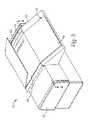
- FIG. 1is a perspective view of one exemplary embodiment of a reader for reading and authenticating a composite image in a sheeting of the present invention
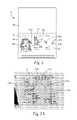
- FIG. 2is a top view of a passport including composite images that appear to float above and appear to float below the sheeting;
- FIG. 2 ais a photomicrograph of a passport including composite images that appear to float above and appear to float below the sheeting;
- FIG. 3is a perspective view of the passport of FIG. 2 being read by the reader of FIG. 1 ;
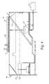
- FIG. 4is a side, cross-sectional, schematic view of the passport reader and passport of FIG. 3 ;
- FIG. 5illustrates a schematic view of one exemplary embodiment of the cameras in the system for reading and authenticating a composite image in a sheeting of the present invention
- FIG. 6illustrates a schematic view of another exemplary embodiment of the camera in the system for reading and authenticating a composite image in a sheeting of the present invention
- FIG. 7illustrates a schematic view of yet another exemplary embodiment of the camera in the system for reading and authenticating a composite image in a sheeting of the present invention.
- FIG. 8illustrates the optics associated with the embodiments of the systems illustrated in FIGS. 5-7 .
- the system of the present inventionreads a composite image that appears to be suspended, or to float, above, in the plane of, and/or below a sheeting.
- the system of the present inventionis also useful for providing information to a user whether or not a sheeting having such a composite image is authentic or not.
- the system of the present inventionis for reading and authenticating a composite image that appears to the unaided eye to be floating above or below a sheeting or both, such a floating composite image as taught in U.S. Pat. No. 6,288,842 B1, (“the '842 patent”), “Sheeting with Composite Image that Floats,” (Florczak et al.), which is owned by the same assignee as the present application, and which is hereby incorporated by reference.
- composite imagesare actually three-dimensional, optical illusions, and they are perceived by the user to either be floating above or below the sheeting or both.
- the system of the present inventionassists in calculating the distance that is perceived by the user between the composite image and the sheeting in this optical illusion.
- Composite images that appear to the unaided eye to be floating above a sheeting, below a sheeting, or both,are suspended images and are referred to for convenience as floating images.
- the term “unaided eye”means normal (or corrected to normal) human vision not enhanced by, for example, magnification.
- These suspended or floating imagesmay be either two or three-dimensional images, can be in black or white or in color, and can appear to move with the observer or change in shape.
- the sheeting that has a composite imagemay be viewed using light that impinges on the sheeting from the same side as the observer (reflected light), or from the opposite side of the sheeting as the observer (transmitted light), or both.
- FIG. 2 aOne example of sheeting including such composite images is shown in FIG. 2 a , which is explained in more detail below.
- the sheetingincludes: (a) at least one layer of microlens, the layer having first and second sides; (b) a layer of material disposed adjacent the first side of the layer of microlens; and (c) an at least partially complete image formed in the material associated with each of a plurality of the microlens, where the image contrasts with the material.
- Microlensmay also be called lenticular lens or microlenslets.
- the composite imageis provided by the individual images, and it appears to the unaided eye to be floating above or below the sheeting, or both.
- the '842 patentprovides a complete description of the microlens sheeting, exemplary material layers of such sheeting, some of which are preferably radiation sensitive material layers, examples of radiation sources for creating the individual images, and exemplary imaging processes.
- the sheeting having a composite image as described in the '842 patentmay be used in a variety of applications such as securing tamperproof images in passports, ID badges, event passes, affinity cards, or other documents of value, product identification formats and advertising promotions for verification and authenticity, brand enhancement images which provide a floating or sinking or a floating and sinking image of the brand, identification presentation images in graphics applications such as emblems for police, fire or other emergency vehicles; information presentation images in graphics applications such as kiosks, night signs and automotive dashboard displays, and novelty enhancement through the use of composite images on products such as business cards, hang-tags, art, shoes and bottled products.
- the system of the present invention for reading and authenticating sheeting having a composite imageincludes a reader for reading and authenticating any of the items mentioned above.
- the figures of the present applicationillustrate a passport having a floating image and a passport reader for reading and authenticating the floating image.
- the system of the present inventionmay include any reader for reading and authenticating any item having a floating image.
- FIG. 1illustrates one embodiment of a reader 10 that is a part of the system of the present invention for reading and authenticating a floating image.
- the reader 10is configured to read passports having floating images.
- the passport reader 10includes a housing 50 .
- the housing 50includes a first portion 42 and a second portion 44 .
- the first portion 42includes a window 40 , preferably made of glass, which is convenient for viewing the optical information found in the passport, such as printed images, photographs, signatures, personal alphanumeric information, and barcodes, and for viewing the floating images on the passport.
- the second portion 44 of the passport readerincludes a ledge, which is convenient for supporting half of a passport when the passport 14 is inserted into the passport reader 10 to be read (shown in FIG. 2 ). The other half of the passport is placed on the glass 40 when the passport 14 is inserted into the passport reader 10 to be read and authenticated or verified.
- FIG. 2illustrates one embodiment of a schematic document of value including a floating image.
- FIG. 2 ais a photomicrograph of a close up view of a portion of an actual document of value including floating images.
- the document of valueis a passport booklet 14 .
- the passport 14is typically a booklet filled with several bound pages.
- One of the pagesusually includes personalization data 18 , often presented as printed images, which can include photographs 16 , signatures, personal alphanumeric information, and barcodes, and allows human or electronic verification that the person presenting the document for inspection is the person to whom the passport 14 is assigned.
- This same page of the passportmay have a variety of covert and overt security features, such as those security features described in U.S. patent application Ser. No.
- this same page of the passport 14includes a laminate of microlens sheeting 20 having composite images 30 , which appear to the unaided eye to float either above or below the sheeting 20 or both.
- This featureis a security feature that is used to verify that the passport is an authentic passport and not a fake passport.
- suitable microlens sheeting 20is commercially available from 3M Company based in St. Paul, Minn. as 3MTM ConfirmTM Security Laminate with Floating Images.
- the composite images 30 or floating images 30include three different types of floating images.
- the first type of floating image 30 ais a “3M” that appears to the unaided eye to float above the page in the passport 14 .
- the second type of floating image 30 bis a “3M” that appears to the unaided eye to float below the page in the passport 14 .
- the third type of floating image 30 cis a sine wave that appears to the unaided eye to float above the page in the passport 14 .
- the floating images 30 a , 30 b , 30 cmay appear to move to the observer.
- the floating images 30 a , 30 b , 30 care optical illusions that appear to the viewer's unaided eye to be floating above or below the sheeting 20 or both.
- the passport 14 or document of valuemay include any combination of floating images that float above, below and/or in the plane of the passport 14 .
- the floating imagesmay be any configuration and may include words, symbols, or particular designs that correspond to the document of value.
- passports issued by the Australian governmentinclude microlens sheeting having floating images in the shape of a kangaroo and boomerangs, two symbols representing the country.
- the other pages of the passport bookletmay contain blank pages for receiving a country's stamp, as the person is processed through customs.
- the customs officialwould typically look at the passport 14 with his unaided eyes to see if the passport included the appropriate floating images 30 to verify that the passport was authentic.
- the system of the present inventionfirst verifies that the passport or document of value contains at least one floating image 30 . Then, the system verifies that the floating image 30 is the correct floating image 30 .
- the systemverifies the perceived distance between the floating image 30 and the passport page having the microlens sheeting, known as the “floating distance.” If this floating distance is the correct distance or within some margin of error, then the system verifies or authenticates or otherwise communicates to the customs official that the passport is an authentic passport. If, however, the floating distance is not the correct distance, the system indicates to the customs official that the passport is a forgery or a fake. The system also helps reduce time and effort spent by the customs official processing the passport.
- FIG. 3illustrates the passport reader 10 of the system in combination with a passport 14 .
- the passport booklet 14is opened up to the page containing the floating images, creating a first portion 46 of the passport and second portion 48 of the passport.
- the page of the passport 14 having the floating imagesis the same page that contains the personalization data 18 , such as the picture 16 of the individual carrying the passport.
- the passport bookletis inserted into the passport reader 10 , such that the floating images 30 and the personalization data 18 in the first portion 46 of the passport 14 are adjacent (or placed over) the glass 40 of the reader 10 .
- the second portion 48 of the passport 14is in contact with the ledge 44 of the reader, and the seam of the passport 14 extends along the junction between adjacent edges of the glass 40 and the ledge 44 .
- This placement of the passport 14 on the passport reader 50is convenient for reading the floating images 30 and the personalization data 18 , which is explained in more detail below in reference to FIGS. 4-7 .
- FIG. 4is convenient for illustrating the inside of the passport reader 14 when the passport is being read and verified.
- the passport reader 14can read the personalization data 18 from the passport and to perform this feature, the passport reader 14 contains many of the same parts (not illustrated) as the Full Page Readers sold under the 3M brand from 3M Company located in St. Paul, Minn.
- the cameras in the reader 10are also used to record and transmit the personalization information on the passport to the computer.
- the difference between the passport reader 14 of the system of the present invention and the Full Page Readersis that the passport reader 14 of the present invention can read and authenticate floating images 30 .
- the passport reader 14includes light source 52 , a mirror 54 , and at least a first camera 58 .
- the reader 14may optionally include a second camera 60 ( FIG. 5 .).
- the mirror 54is preferably a half-silvered mirror that can both reflect and transmit light.
- the microlens sheeting 20 on the passport 14is viewable through the glass window 40 .
- the microlens sheeting 20preferably includes a layer of microlens 22 and a layer of radiation sensitive material layer 24 .
- the mirror 54is positioned at a 45° angle relative to both the light source 52 and the camera 58 .
- This arrangementis such that the light from the light source 52 is reflected off the half-silvered mirror, up to the microlens sheeting or substrate 20 through the glass 40 , and then reflected back down through the half-silvered mirror 54 and into the camera 58 , as illustrated in FIG. 4 .
- the light source 52may provide light of a certain wavelength, polarized light, or retroreflected light.
- retroreflectedrefers to the attribute of reflecting an incident light ray in a direction antiparallel to its incident direction, or nearly so, such that it returns to the light source or the immediate vicinity thereof. Retroreflected light is preferred because it helps eliminate viewing the printed personalization information on the passport 14 , making the floating image 30 easier to view.
- the reader 10may include a stationary camera 58 , one moveable camera 58 a , or two cameras 58 , 60 , as discussed in more detail in reference to FIGS. 5-8 .
- a suitable light source 52is commercially available from Lumex, Inc. located in Palatine, Ill., a white, clear lens, TI format LED, under part number SSL-LX3054 UWC/A.
- a suitable camera 58is commercially available from Micron Technology, Inc. located in Boise, Id. as a 1.3 Mega-pixel CMOS color sensor camera.
- One example of a suitable half-silvered mirror 54is commercially available from Edmund Industrial Optics located in Barrington, N.J., having part number NT43-817.
- the systemincludes a computer 56 (illustrated as box 56 ) in communication with the camera 58 .
- the computer 56processes the information obtained by either the first camera 58 , second camera 60 or both cameras 58 , 60 .
- Any computer known in the artis suitable to be used in the passport reader 10 .
- FIGS. 5-8illustrate three different embodiments of the reader 10 .
- the reader 10includes a first camera 58 and a second camera 60 .
- the readerincludes a first moveable camera 58 a .
- the camera 58 amay move along a track inside the reader and be powered by a motor.
- the camera 58is stationary, but a holder 38 a of the passport 14 is moveable relative to the camera 58 .
- the holder 38 amay move along a track on top of the reader and be powered by a motor.
- the holder 38 apreferably includes the glass 40 .
- the images of the microlens sheeting 20 and floating image 30are captured on the camera image planes 66 , 68 and transmitted to the computer 56 for further processing.
- the first image 70 and second image 72 of the microlens sheetingare depicted graphically by boxes 70 and 72 .
- the first image 74 and second image 76 of the composite floating image 30are depicted graphically by boxes 74 and 76 .
- the first image 70 and second image 72 of the microlens sheetingare compared by the computer 56 .
- the first image 74 and second image 76 of the floating image 30are compared by the computer 56 .
- the images 70 , 72 , 74 , 76are measured relative to the center of the camera planes 66 , 68 as discussed in reference to FIG. 8 .
- FIG. 8illustrates the optics associated with the embodiments of the system illustrated in FIGS. 5-7 .
- FIG. 8illustrates a first camera image plane 66 and a second camera image plane 68 .
- the first image plane 66may be part of the first camera 58 and the second image plane 68 may be part of a second camera 60 , as illustrated in FIG. 5 .
- the first image plane 66may represent one camera 58 a in a first position and the second image plane 68 may represent the same camera in a second position, as illustrated in FIG. 6 .
- the optics illustrated in FIG. 8represent the same relative measurements for the embodiment illustrated in FIG. 7 , where the microlens sheeting 20 moves relative to the camera 58 .
- the optics illustrated in FIG. 8represent the same measurements for whether the composite image 30 is floating above or below the sheeting 20 .
- the position of the sheetingis fixed during the first and second pictures of the sheeting 20 by either the first and second camera 58 , 60 or by the single camera 58 .
- the single camera 58is fixed during the first and second pictures of the sheeting 20 and the sheeting 20 moves from a first position and to a second position using holder 38 a .
- the systempreferably captures two images of the composite sheeting 20 and the floating image 30 from two different perspectives.
- the measurements illustrated in FIG. 8are for calculating the distance “p” between the microlens sheeting 20 in the passport 14 and the floating image 30 floating above or below the sheeting, which is useful for authenticating or verifying the sheeting 20 .
- the systemis comparing the first image and the second image of the microlens sheeting and comparing the first image and second image of the composite image floating above or below the sheeting, so that the images will cancel each other out, except for the floating distance.
- the first camera 58includes a first camera lens 62 and a first camera image plane 66 and the second camera 60 includes a second camera lens 64 and a second camera image plane 68 .
- the first and second cameras 58 , 60both include a focal length “f” of their lens 62 , 64 .
- the first and second cameras 58 , 60are similar cameras with the same focal lengths.
- the first camera image plane 66has a center point 78 .
- the second camera image plane 68has a center point 80 .
- the local length “f”is measured from the center point of the camera image planes to the lens of the cameras.
- the first camera 58takes a first picture, records or captures a first image of the sheeting 20 and the floating image 30 .
- the second camera 60takes a second picture, records or captures a second image of the sheeting 20 and the floating image 30 .
- the first image of the microlens sheeting 20is represented schematically on the first camera image plane 66 as reference number 70 .
- the first image of the floating image 30is represented schematically on the first camera image plane 66 as reference number 72 .
- the second image of the microlens sheeting 20is represented schematically on the second camera image plane 68 as reference number 74 .
- the second image of the floating image 30is represented on the second camera image plane 68 as reference number 76 .
- the lens 62 , 64 of the cameras 58 , 60are preferably orthogonal relative to the microlens sheeting 20 .
- Distance “a”is the distance between the second image 74 of the microlens sheeting on the camera image plane 68 and the center 80 of the camera image plane 68 .
- Distance “b”is the distance between the second image 76 of the floating image 30 on the camera image plane 68 and the center 80 of the camera image plane 68 .
- Distance “d”is the distance between the first image 72 of the floating image 30 on the camera image plane 66 and the center 78 of the camera image plane 66 .
- Distance “c”is the distance between the first image 70 of the microlens sheeting on the camera image plane 66 and the center 78 of the camera image plane 66 .
- Distance “e”is the known distance between the centers of the lens 62 , 64 of the cameras.
- Distance “g”is the known orthogonal distance between the lens 62 , 64 of the cameras 58 , 60 and the microlens sheeting 20 . A relational point other than the center point of lens could be used with appropriate modification of the math formulas.
- the systemcan measure distances “a”, “b”, “c”, and “d”.
- the distances “e”, “f”, and “g”are known distances based on how the reader 10 is built.
- the floating distance or distance pis the unknown distance.
- the example belowprovides calculation of actual floating distance based on the formulas above.
- the system's computer 56calculates the floating distance “p.” Then, the computer can compare the floating distance to the database of floating distances. This enables inspection authorities to identify any anomalies or discrepancies between the data presented by a traveler and data held in databases. If the calculated floating distance matches the floating distance in the database for the identified composite image 30 , then the system authenticates the sheeting 20 . If the calculated floating distance does not match the floating distances in the database for the identified composite image 30 , then the system determines that the sheeting is not authentic.
- the systemincludes at least one camera that takes a first image and a second image of the microlens sheeting 20 having a floating image 30 .
- the cameramay move in any direction relative the sheeting 20 to obtain these first and second images. For instance, the camera may move in the x, y, or z direction relative to the sheeting 20 . Alternatively, the camera may rotate around its center of mass relative to the sheeting. In addition, the camera may take multiple images of the sheeting and composite images.
- the readermay have a one fixed focal-length camera.
- the single focus camerais moveable between a first position and a second position perpendicular to the sheeting 20 .
- the cameramoves along a track between the first position and the second position.
- the cameramoves until the microlens sheeting 20 comes into full focus, which establishes the first position of the camera.
- the cameracaptures a first image of the sheeting 20 and the composite image 30 .
- the cameramoves until the composite image 30 comes into full focus, which establishes the second position of the camera.
- the cameracaptures a second image of the microlens sheeting 20 and the composite image 30 .
- the distance between the first camera position and the second camera positionis the distance “p” between the microlens sheeting 20 in the passport 14 and the perceived distance of the floating image 30 floating above or below the sheeting or both.
- the reader 10is capable of locating the floating image 30 and identifying the floating image 30 .
- the camerawill first record the floating image 30 and then the computer 56 will compare the recorded floating image 30 with a database of floating images to identify the floating image.
- the computer 56preferably includes a template matching program or a normalization correlation matrix, which compares a known image with a recorded image.
- a normalization correlationis described in Computer Vision by Dana Bollard and Christopher Brown, copyright 1982, published by Prentice Hall, Inc., pages 65-70, which are hereby incorporated by reference.
- the reader 10may include radio-frequency identification (“RFID”) reading capabilities.
- RFIDradio-frequency identification
- the reader 10may include the features disclosed in U.S. patent application Ser. No. 10/953,200, “A Passport Reader for Processing a Passport Having an RFID Element,” (Jesme), which is hereby incorporated by reference. The system will read and authenticate a variety of different floating images.
- the floating distancemay vary from one sheeting to another.
- the systemreads a security code embedded in the sheeting that contains information relating to the floating distance of that sheeting and authenticates the sheeting only if the calculated floating distance matches the floating distance provided in the security code.
- the security codeis used to retrieve the proper floating distance from a database of floating distances.
- the camera lens 62was located at a measured distance of 12.5 centimeters (‘g’ in FIG. 8 ) from the microlens sheeting 20 .
- the microlens sheeting with the floating imagewas a sample of 3MTM ConfirmTM Security Laminate with Floating Images which is commercially available from 3M Company located in, St. Paul, Minn., as part number ES502.
- a first image of the microlens sheeting and of the composite imagewas captured.
- the camerawas then moved laterally and a second image of the microlens sheeting and the composite image was captured.
- the first image of the microlens sheeting and composite imagewere first used to identify if the microlens sheeting had a composite image and to verify if the composite image was the correct image.
- the computerran the template matching program which was based on the normalization correlation matrix disclosed in Computer Vision by Dana Bollard and Christopher Brown, published by Prentice-Hall, Inc., copyright 1982, pages 65-70, which has been incorporated by reference. Using the template matching program, the computer was able to identify at least one of the floating images and verify that the floating image was what was expected.
- Distances ‘c ⁇ a’ and ‘d ⁇ b’were determined by the computer. Since the camera captures the images in discrete pixels and the pixel density of the images formed by the camera is known, i.e. the number of pixels per millimeter is known, the computer can calculate the distances a, b, c and d. The computer calculates ‘a’—the distance between points 72 and 80 , ‘b’—the distance between points 76 and 80 , ‘c’—the distance between points 70 and 78 and ‘d’—the distance between points 74 and 78 by counting the number of pixels in each respective length, i.e.
- the computer determined values for c ⁇ a and d ⁇ bwas 7.6 millimeters and 8.3 millimeters respectively.
- the systemverifies the security laminate with the floating images as an authentic security laminate.
- test results described aboveare intended solely to be illustrative, rather than predictive, and variations in the testing procedure can be expected to yield different results.
Landscapes
- Health & Medical Sciences (AREA)
- General Health & Medical Sciences (AREA)
- Toxicology (AREA)
- Physics & Mathematics (AREA)
- General Physics & Mathematics (AREA)
- Computer Vision & Pattern Recognition (AREA)
- Engineering & Computer Science (AREA)
- Credit Cards Or The Like (AREA)
- Image Input (AREA)
- Inspection Of Paper Currency And Valuable Securities (AREA)
- Image Processing (AREA)
- Editing Of Facsimile Originals (AREA)
- User Interface Of Digital Computer (AREA)
- Character Input (AREA)
Abstract
Description
h/e=f/(d−b)andg/e=f(c−a)
h=g(c−a)/(d−b)
p=g−h
The example below provides calculation of actual floating distance based on the formulas above.
h=g(c−a)/(d−b)=12.5(0.76)/(0.83)=11.45 centimeters
p=g−h=12.5−11.45=1.05 centimeters
Claims (4)
Priority Applications (1)
| Application Number | Priority Date | Filing Date | Title |
|---|---|---|---|
| US12/544,932US8072626B2 (en) | 2004-12-02 | 2009-08-20 | System for reading and authenticating a composite image in a sheeting |
Applications Claiming Priority (2)
| Application Number | Priority Date | Filing Date | Title |
|---|---|---|---|
| US11/002,943US7616332B2 (en) | 2004-12-02 | 2004-12-02 | System for reading and authenticating a composite image in a sheeting |
| US12/544,932US8072626B2 (en) | 2004-12-02 | 2009-08-20 | System for reading and authenticating a composite image in a sheeting |
Related Parent Applications (1)
| Application Number | Title | Priority Date | Filing Date |
|---|---|---|---|
| US11/002,943DivisionUS7616332B2 (en) | 2004-12-02 | 2004-12-02 | System for reading and authenticating a composite image in a sheeting |
Publications (2)
| Publication Number | Publication Date |
|---|---|
| US20090310824A1 US20090310824A1 (en) | 2009-12-17 |
| US8072626B2true US8072626B2 (en) | 2011-12-06 |
Family
ID=35809688
Family Applications (2)
| Application Number | Title | Priority Date | Filing Date |
|---|---|---|---|
| US11/002,943Active2028-08-14US7616332B2 (en) | 2004-12-02 | 2004-12-02 | System for reading and authenticating a composite image in a sheeting |
| US12/544,932Expired - LifetimeUS8072626B2 (en) | 2004-12-02 | 2009-08-20 | System for reading and authenticating a composite image in a sheeting |
Family Applications Before (1)
| Application Number | Title | Priority Date | Filing Date |
|---|---|---|---|
| US11/002,943Active2028-08-14US7616332B2 (en) | 2004-12-02 | 2004-12-02 | System for reading and authenticating a composite image in a sheeting |
Country Status (19)
| Country | Link |
|---|---|
| US (2) | US7616332B2 (en) |
| EP (1) | EP1836688B1 (en) |
| JP (1) | JP4468993B2 (en) |
| KR (1) | KR101185665B1 (en) |
| CN (1) | CN101069216B (en) |
| AR (1) | AR051976A1 (en) |
| AT (1) | ATE406636T1 (en) |
| AU (1) | AU2005310220B2 (en) |
| BR (1) | BRPI0518774A2 (en) |
| CA (1) | CA2589350C (en) |
| DE (1) | DE602005009403D1 (en) |
| ES (1) | ES2313440T3 (en) |
| IL (1) | IL183477A (en) |
| MX (1) | MX2007006450A (en) |
| NZ (1) | NZ555679A (en) |
| RU (1) | RU2382415C2 (en) |
| TW (1) | TW200636590A (en) |
| WO (1) | WO2006060090A1 (en) |
| ZA (1) | ZA200705205B (en) |
Families Citing this family (22)
| Publication number | Priority date | Publication date | Assignee | Title |
|---|---|---|---|---|
| US7616332B2 (en) | 2004-12-02 | 2009-11-10 | 3M Innovative Properties Company | System for reading and authenticating a composite image in a sheeting |
| DE102005039320A1 (en)* | 2005-08-19 | 2007-02-22 | Giesecke & Devrient Gmbh | Card-shaped data carrier |
| US7800825B2 (en)* | 2006-12-04 | 2010-09-21 | 3M Innovative Properties Company | User interface including composite images that float |
| US7546957B2 (en)* | 2007-05-29 | 2009-06-16 | Ncr Corporation | Travel kiosk |
| CN101878438B (en) | 2007-11-27 | 2013-09-25 | 3M创新有限公司 | Method of forming sheet with suspended composite image and master mold |
| US8162219B2 (en)* | 2008-01-09 | 2012-04-24 | Jadak Llc | System and method for logo identification and verification |
| US7995278B2 (en)* | 2008-10-23 | 2011-08-09 | 3M Innovative Properties Company | Methods of forming sheeting with composite images that float and sheeting with composite images that float |
| JP2012520508A (en) | 2009-03-10 | 2012-09-06 | スリーエム イノベイティブ プロパティズ カンパニー | User interface with floating composite image |
| EP2320390A1 (en)* | 2009-11-10 | 2011-05-11 | Icar Vision Systems, SL | Method and system for reading and validation of identity documents |
| US9716711B2 (en)* | 2011-07-15 | 2017-07-25 | Pagemark Technology, Inc. | High-value document authentication system and method |
| WO2013179249A1 (en)* | 2012-05-30 | 2013-12-05 | Label Tech International Trims Limited | Authentication apparatus and methods |
| DE102013110165A1 (en) | 2013-09-16 | 2015-03-19 | Bundesdruckerei Gmbh | document examination |
| DE102014100532A1 (en)* | 2014-01-17 | 2015-07-23 | Bundesdruckerei Gmbh | Method for verifying the authenticity of an identification document |
| TWI523485B (en)* | 2014-03-10 | 2016-02-21 | 虹光精密工業股份有限公司 | Multi-purpose scanner |
| DE102014111171A1 (en)* | 2014-08-06 | 2016-02-11 | Bundesdruckerei Gmbh | An image capture device for capturing a first image of an identification document in a first wavelength range and a second image of the identification document in a second wavelength range |
| US10826900B1 (en)* | 2014-12-31 | 2020-11-03 | Morphotrust Usa, Llc | Machine-readable verification of digital identifications |
| CN105632012A (en)* | 2016-03-03 | 2016-06-01 | 深圳市中钞信达金融科技有限公司 | Method, device and system for bill authenticity identification |
| DE102016107900B4 (en)* | 2016-04-28 | 2020-10-08 | Carl Zeiss Industrielle Messtechnik Gmbh | Method and device for determining the edge of a measurement object in optical measurement technology |
| US10033980B2 (en) | 2016-08-22 | 2018-07-24 | Amazon Technologies, Inc. | Determining stereo distance information using imaging devices integrated into propeller blades |
| US10607310B1 (en)* | 2017-10-17 | 2020-03-31 | Amazon Technologies, Inc. | Determining ranges by imaging devices with dynamic baseline reconfiguration |
| FR3109657B1 (en)* | 2020-04-28 | 2022-09-09 | Idemia France | security device based on a grayscale image |
| CN112734688B (en)* | 2020-12-11 | 2025-03-14 | 江苏大学 | Potato browning detection method based on machine vision |
Citations (174)
| Publication number | Priority date | Publication date | Assignee | Title |
|---|---|---|---|---|
| US1905716A (en) | 1931-04-03 | 1933-04-25 | Bell Telephone Labor Inc | Making stereoscopic parallax panoramagrams from pseudoscopic parallax panoramagrams |
| US1918705A (en) | 1930-12-20 | 1933-07-18 | Herbert E Ives | Parallax panoramagram |
| US2039648A (en) | 1933-05-06 | 1936-05-05 | Perser Corp | Camera for making parallax panoramagrams |
| US2063985A (en) | 1935-05-24 | 1936-12-15 | Winnek Stereoscopic Processes | Apparatus for making a composite stereograph |
| US2279825A (en) | 1940-07-24 | 1942-04-14 | Nicholas T Kaszab | Stereoscopic picture with aplanat focusing element |
| US2326634A (en) | 1941-12-26 | 1943-08-10 | Minnesota Mining & Mfg | Reflex light reflector |
| US2500511A (en) | 1944-07-10 | 1950-03-14 | Reliephographie Soc Pour L Exp | Relief photograph having reflecting back |
| US2622472A (en) | 1946-05-25 | 1952-12-23 | Reliephographie Soc Pour L Exp | Apparatus for relief and movement photography |
| US2833176A (en) | 1953-07-21 | 1958-05-06 | Ossoinak Andres Juan Luis | Arrangement for the exhibition of dynamic scenes to an observer in movement with respect to a screen |
| US3154872A (en) | 1963-02-13 | 1964-11-03 | Minnesota Mining & Mfg | Tamper-proof markings for reflecting structures |
| US3161509A (en) | 1962-04-24 | 1964-12-15 | Eastman Kodak Co | Line stereo color pictures |
| US3306974A (en) | 1963-03-08 | 1967-02-28 | Gilbert R Johnson | Color reproduction with a monochromatic gradient line image |
| US3357770A (en) | 1961-10-02 | 1967-12-12 | Intermountain Res And Engineer | Stereoscopic viewing apparatus which includes a curved lenticular screen in front ofa curved picture supporting surface |
| US3365350A (en) | 1965-04-28 | 1968-01-23 | Cahn Leo | Three dimensional picture |
| US3442569A (en) | 1962-09-29 | 1969-05-06 | Centre Nat Rech Scient | Devices for producing virtual images |
| US3459111A (en) | 1966-06-20 | 1969-08-05 | Polaroid Corp | Image dissection camera |
| US3503315A (en) | 1966-12-12 | 1970-03-31 | Lucas Industries Ltd | Integral photography |
| US3584369A (en) | 1967-10-11 | 1971-06-15 | Roger Lannes De Montebello | Process of making reinforced lenticular sheet |
| US3607273A (en) | 1967-03-08 | 1971-09-21 | American Screen Process Equip | Image formation by selective foam generation |
| US3613539A (en) | 1968-07-26 | 1971-10-19 | Leslie Peter Dudley | Integral photography |
| US3671122A (en) | 1970-10-02 | 1972-06-20 | Dudley Optical Lab Inc | Methods of printing stereoscopic integral photograph from pseudoscopic original |
| US3676130A (en) | 1969-11-26 | 1972-07-11 | Bell Telephone Labor Inc | Beaded plate integral photography |
| US3683773A (en) | 1968-07-26 | 1972-08-15 | Dudley Optical Lab Inc | Stereoscopic photography |
| US3706486A (en) | 1970-08-27 | 1972-12-19 | Roger De Montebello | Reinforced lenticular sheet with plural apertured sheets |
| GB1308116A (en) | 1970-08-17 | 1973-02-21 | Agfa Gevaert Ag | Method and apparatus for printing coloured images |
| US3751258A (en) | 1970-10-29 | 1973-08-07 | Eastman Kodak Co | Autostereographic print element |
| US3801183A (en) | 1973-06-01 | 1974-04-02 | Minnesota Mining & Mfg | Retro-reflective film |
| GB1433025A (en) | 1972-06-29 | 1976-04-22 | Sublistatic Holding Sa | Reproducing a multi-coloured image |
| US4034555A (en) | 1975-12-16 | 1977-07-12 | Rosenthal Bruce A | Lenticular optical system |
| US4082426A (en) | 1976-11-26 | 1978-04-04 | Minnesota Mining And Manufacturing Company | Retroreflective sheeting with retroreflective markings |
| US4099838A (en) | 1976-06-07 | 1978-07-11 | Minnesota Mining And Manufacturing Company | Reflective sheet material |
| US4121011A (en) | 1975-11-28 | 1978-10-17 | Raychem Corporation | Polymeric article coated with a thermochromic paint |
| US4200875A (en) | 1978-07-31 | 1980-04-29 | The United States Of America As Represented By The Secretary Of The Air Force | Apparatus for, and method of, recording and viewing laser-made images on high gain retroreflective sheeting |
| US4315665A (en) | 1979-09-07 | 1982-02-16 | Eidetic Images, Inc. | Composite optical element having controllable light transmission and reflection characteristics |
| GB2083726A (en) | 1980-09-09 | 1982-03-24 | Minnesota Mining & Mfg | Preparation of multi-colour prints by laser irradiation and materials for use therein |
| US4420527A (en) | 1980-09-05 | 1983-12-13 | Rexham Corporation | Thermoset relief patterned sheet |
| US4424990A (en) | 1980-01-30 | 1984-01-10 | Raychem Corporation | Thermochromic compositions |
| US4541830A (en) | 1982-11-11 | 1985-09-17 | Matsushita Electric Industrial Co., Ltd. | Dye transfer sheets for heat-sensitive recording |
| US4541727A (en) | 1975-12-16 | 1985-09-17 | Rosenthal Bruce A | Lenticular optical system |
| US4552442A (en) | 1982-04-07 | 1985-11-12 | Street Graham S B | Method and apparatus for use in producing autostereoscopic images |
| US4557590A (en) | 1982-09-10 | 1985-12-10 | Winnek Douglas Fredwill | Method and apparatus for making true three-dimensional photographs from pseudo three-dimensional photographs |
| US4618552A (en) | 1984-02-17 | 1986-10-21 | Canon Kabushiki Kaisha | Light receiving member for electrophotography having roughened intermediate layer |
| US4621898A (en) | 1983-03-17 | 1986-11-11 | Allied Corporation | Directional optical filter |
| US4629667A (en) | 1985-03-29 | 1986-12-16 | Minnesota Mining And Manufacturing Company | White reflective coating |
| US4632895A (en) | 1984-08-23 | 1986-12-30 | Minnesota Mining And Manufacturing Company | Diffusion or sublimation transfer imaging system |
| US4634220A (en) | 1983-02-07 | 1987-01-06 | Minnesota Mining And Manufacturing Company | Directionally imaged sheeting |
| US4650283A (en) | 1984-08-03 | 1987-03-17 | Minnesota Mining And Manufacturing Company | Directionally imaged retroreflective sheeting |
| US4668063A (en) | 1983-10-03 | 1987-05-26 | Street Graham S B | Stereoscopic recording method and apparatus, and production method and apparatus |
| US4688894A (en) | 1985-05-13 | 1987-08-25 | Minnesota Mining And Manufacturing Company | Transparent retroreflective sheets containing directional images and method for forming the same |
| US4700207A (en) | 1985-12-24 | 1987-10-13 | Eastman Kodak Company | Cellulosic binder for dye-donor element used in thermal dye transfer |
| US4708920A (en) | 1985-09-16 | 1987-11-24 | Minnesota Mining And Manufacturing Company | Microlens sheet containing directional half-tone images and method for making the same |
| US4714656A (en) | 1985-09-23 | 1987-12-22 | Minnesota Mining And Manufacturing Company | Sheet containing contour-dependent directional image and method for forming the same |
| US4732453A (en) | 1984-12-10 | 1988-03-22 | Integrated Images, Inc. | Integral photography apparatus and method of forming same |
| US4743526A (en) | 1984-12-03 | 1988-05-10 | Hitachi, Ltd. | Alloy having variable spectral reflectance and information recording material making use of the same |
| US4765656A (en) | 1985-10-15 | 1988-08-23 | Gao Gesellschaft Fur Automation Und Organisation Mbh | Data carrier having an optical authenticity feature and methods for producing and testing said data carrier |
| US4772582A (en) | 1987-12-21 | 1988-09-20 | Eastman Kodak Company | Spacer bead layer for dye-donor element used in laser-induced thermal dye transfer |
| US4775219A (en) | 1986-11-21 | 1988-10-04 | Minnesota Mining & Manufacturing Company | Cube-corner retroreflective articles having tailored divergence profiles |
| US4783141A (en) | 1984-03-14 | 1988-11-08 | Canon Kabushiki Kaisha | Array lens |
| US4799739A (en) | 1987-08-10 | 1989-01-24 | Advanced Dimensional Displays, Inc. | Real time autostereoscopic displays using holographic diffusers |
| US4833124A (en) | 1987-12-04 | 1989-05-23 | Eastman Kodak Company | Process for increasing the density of images obtained by thermal dye transfer |
| US4876235A (en) | 1988-12-12 | 1989-10-24 | Eastman Kodak Company | Dye-receiving element containing spacer beads in a laser-induced thermal dye transfer |
| US4892336A (en) | 1986-03-18 | 1990-01-09 | Gao Gesellschaft Fuer Automation Und Organisation Mbh | Antifalsification document having a security thread embedded therein and a method for producing the same |
| US4917292A (en) | 1988-04-21 | 1990-04-17 | Drexler Technology Corporation | Book on a pocket card |
| US4920039A (en) | 1986-01-06 | 1990-04-24 | Dennison Manufacturing Company | Multiple imaging |
| US4927238A (en) | 1984-11-27 | 1990-05-22 | Nicholas C. Terzis | Method and apparatus for displaying a three dimensional visual image |
| US4935335A (en) | 1986-01-06 | 1990-06-19 | Dennison Manufacturing Company | Multiple imaging |
| EP0404004A3 (en) | 1989-06-19 | 1991-10-16 | Nippon Unicar Company Limited | A shape memory elastic body |
| US5064272A (en) | 1985-11-18 | 1991-11-12 | Minnesota Mining And Manufacturing Company | Encapsulated-lens retroreflective sheeting and method of making |
| US5091483A (en) | 1989-09-22 | 1992-02-25 | Minnesota Mining And Manufacturing Company | Radiation-curable silicone elastomers and pressure sensitive adhesives |
| US5105206A (en) | 1989-12-27 | 1992-04-14 | Eastman Kodak Company | Thermal printer for producing transparencies |
| US5169707A (en) | 1991-05-08 | 1992-12-08 | Minnesota Mining And Manufacturing Company | Retroreflective security laminates with dual level verification |
| US5204160A (en) | 1988-08-08 | 1993-04-20 | Minnesota Mining And Manufacturing Company | Light-collimating film |
| US5244288A (en) | 1991-07-15 | 1993-09-14 | Mitsubishi Jukogyo Kabushiki Kaisha | Method and apparatus for braille display of information from crt screen |
| US5254390A (en) | 1990-11-15 | 1993-10-19 | Minnesota Mining And Manufacturing Company | Plano-convex base sheet for retroreflective articles and method for making same |
| US5279912A (en) | 1992-05-11 | 1994-01-18 | Polaroid Corporation | Three-dimensional image, and methods for the production thereof |
| EP0583766A1 (en) | 1992-08-18 | 1994-02-23 | Eastman Kodak Company | Depth image printed on lenticular material |
| US5308737A (en) | 1993-03-18 | 1994-05-03 | Minnesota Mining And Manufacturing Company | Laser propulsion transfer using black metal coated substrates |
| EP0314134B1 (en) | 1987-10-28 | 1994-06-22 | Fuji Photo Film Co., Ltd. | Booklet with photograph |
| US5326619A (en) | 1993-10-28 | 1994-07-05 | Minnesota Mining And Manufacturing Company | Thermal transfer donor element comprising a substrate having a microstructured surface |
| US5330799A (en) | 1992-09-15 | 1994-07-19 | The Phscologram Venture, Inc. | Press polymerization of lenticular images |
| US5359454A (en) | 1992-08-18 | 1994-10-25 | Applied Physics Research, L.P. | Apparatus for providing autostereoscopic and dynamic images |
| US5360694A (en) | 1993-10-18 | 1994-11-01 | Minnesota Mining And Manufacturing Company | Thermal dye transfer |
| US5364740A (en) | 1992-12-30 | 1994-11-15 | Minnesota Mining And Manufacturing Company | Bleaching of dyes in photosensitive systems |
| EP0658443A1 (en) | 1993-12-16 | 1995-06-21 | Minnesota Mining And Manufacturing Company | Nanostructured thermal transfer dye donor element |
| US5449597A (en) | 1966-04-21 | 1995-09-12 | Sawyer; George M. | Lippmann process of color photography, which produces a photograph with a 2-dimensional image, to result in another process of color photography which produces a photograph with a 3-dimensional image |
| EP0673785A1 (en) | 1994-03-24 | 1995-09-27 | Minnesota Mining And Manufacturing Company | Black metal thermally imageable transparency elements |
| US5455689A (en) | 1991-06-27 | 1995-10-03 | Eastman Kodak Company | Electronically interpolated integral photography system |
| EP0363919B1 (en) | 1988-10-14 | 1996-01-31 | Mitsubishi Jukogyo Kabushiki Kaisha | Shape memory film |
| US5491045A (en) | 1994-12-16 | 1996-02-13 | Eastman Kodak Company | Image dye combination for laser ablative recording element |
| US5506300A (en) | 1985-01-04 | 1996-04-09 | Thoratec Laboratories Corporation | Compositions that soften at predetermined temperatures and the method of making same |
| US5514730A (en) | 1991-03-20 | 1996-05-07 | Minnesota Mining And Manufacturing Company | Radiation-curable acrylate/silicone pressure-sensitive adhesive compositions |
| US5521035A (en) | 1994-07-11 | 1996-05-28 | Minnesota Mining And Manufacturing Company | Methods for preparing color filter elements using laser induced transfer of colorants with associated liquid crystal display device |
| US5589246A (en) | 1994-10-17 | 1996-12-31 | Minnesota Mining And Manufacturing Company | Heat-activatable adhesive article |
| US5594841A (en) | 1993-12-27 | 1997-01-14 | Schutz; Stephen A. | Stereogram and method of constructing the same |
| US5639580A (en) | 1996-02-13 | 1997-06-17 | Eastman Kodak Company | Reflective integral image element |
| US5642226A (en) | 1995-01-18 | 1997-06-24 | Rosenthal; Bruce A. | Lenticular optical system |
| US5644431A (en) | 1990-05-18 | 1997-07-01 | University Of Arkansas, N.A. | Directional image transmission sheet and method of making same |
| EP0688351B1 (en) | 1993-03-11 | 1997-08-06 | Minnesota Mining And Manufacturing Company | Radiation curable acrylate/silicone permanently removable pressure sensitive adhesive |
| US5671089A (en) | 1993-05-05 | 1997-09-23 | Allio; Pierre | Device for forming an autostereoscopic image |
| US5680171A (en) | 1993-10-21 | 1997-10-21 | Lo; Allen Kwok Wah | Method and apparatus for producing composite images and 3D pictures |
| US5685939A (en) | 1995-03-10 | 1997-11-11 | Minnesota Mining And Manufacturing Company | Process for making a Z-axis adhesive and establishing electrical interconnection therewith |
| US5689372A (en) | 1995-12-22 | 1997-11-18 | Eastman Kodak Company | Integral imaging with anti-halation |
| US5706133A (en) | 1995-02-09 | 1998-01-06 | Minnesota Mining And Manufacturing Company | Retroreflective signage articles, kits for producing same, and methods of making signage articles |
| US5712731A (en) | 1993-05-11 | 1998-01-27 | Thomas De La Rue Limited | Security device for security documents such as bank notes and credit cards |
| US5717844A (en) | 1993-01-06 | 1998-02-10 | Lo; Allen Kwok Wah | Method and apparatus for producing 3D pictures with extended angular coverage |
| US5744291A (en) | 1997-04-03 | 1998-04-28 | Ip; Sunny Leong-Pang | 3D photographic print material |
| US5757550A (en) | 1995-10-31 | 1998-05-26 | Eastman Kodak Company | Dual-view imaging product |
| US5828488A (en) | 1993-12-21 | 1998-10-27 | Minnesota Mining And Manufacturing Co. | Reflective polarizer display |
| US5850580A (en) | 1992-02-06 | 1998-12-15 | Fuji Photo Film Co., Ltd. | Method and apparatus for recording stereoscopic images and lenticular recording material used thereof |
| US5850278A (en) | 1997-08-28 | 1998-12-15 | Lo; Allen Kwok Wah | Optical 3D printer with extended angular coverage |
| DE19804997C1 (en) | 1997-09-24 | 1999-02-11 | Utsch Kg Erich | Marking symbols in plates, especially vehicle number plates with reflective film on plate substrate |
| US5882774A (en) | 1993-12-21 | 1999-03-16 | Minnesota Mining And Manufacturing Company | Optical film |
| US5894069A (en) | 1997-02-12 | 1999-04-13 | Eastman Kodak Company | Transferring colorant from a donor element to a compact disc |
| US5896230A (en) | 1994-05-03 | 1999-04-20 | National Graphics, Inc. | Lenticular lens with multidimensional display having special effects layer |
| US5935758A (en) | 1995-04-20 | 1999-08-10 | Imation Corp. | Laser induced film transfer system |
| US5945249A (en) | 1995-04-20 | 1999-08-31 | Imation Corp. | Laser absorbable photobleachable compositions |
| CA2326180A1 (en) | 1998-03-27 | 1999-10-07 | Hideyoshi Horimai | Three-dimensional image display |
| US5986781A (en) | 1996-10-28 | 1999-11-16 | Pacific Holographics, Inc. | Apparatus and method for generating diffractive element using liquid crystal display |
| US5994026A (en) | 1998-03-30 | 1999-11-30 | Eastman Kodak Company | Flexographic printing plate with mask layer and methods of imaging and printing |
| US6028621A (en) | 1995-05-16 | 2000-02-22 | Yakubovich; Evsey Isaakovich | Method of forming and reproducing a three-dimensional image and a device for that purpose |
| US6057067A (en) | 1994-07-11 | 2000-05-02 | 3M Innovative Properties Company | Method for preparing integral black matrix/color filter elements |
| US6092465A (en) | 1998-03-03 | 2000-07-25 | United Container Machinery, Inc. | Method and apparatus for providing erasable relief images |
| US6095566A (en) | 1996-03-14 | 2000-08-01 | Kabushiki Kaisha Toshiba | Image recorded product, image recording system, image reproducing system, and recording medium for use to superimpose-record/reproduce additional information |
| US6110645A (en) | 1997-03-13 | 2000-08-29 | Kodak Polychrome Graphics Llc | Method of imaging lithographic printing plates with high intensity laser |
| US6197474B1 (en) | 1999-08-27 | 2001-03-06 | Eastman Kodak Company | Thermal color proofing process |
| US6212805B1 (en) | 1996-01-06 | 2001-04-10 | Contra Vision Limited | Panel with light permeable images |
| US6228555B1 (en) | 1999-12-28 | 2001-05-08 | 3M Innovative Properties Company | Thermal mass transfer donor element |
| US6242152B1 (en) | 2000-05-03 | 2001-06-05 | 3M Innovative Properties | Thermal transfer of crosslinked materials from a donor to a receptor |
| US6280891B2 (en) | 1994-05-04 | 2001-08-28 | Hologram Industries S.A. | Multi-layer assembly and method for marking articles and resulting marked articles |
| EP1130541A2 (en) | 2000-02-23 | 2001-09-05 | Eastman Kodak Company | Data storage and retrieval playback apparatus for a still image receiver |
| US6286873B1 (en) | 1998-08-26 | 2001-09-11 | Rufus Butler Seder | Visual display device with continuous animation |
| US6288842B1 (en) | 2000-02-22 | 2001-09-11 | 3M Innovative Properties | Sheeting with composite image that floats |
| US6351537B1 (en) | 1998-10-05 | 2002-02-26 | 3M Innovative Properties Company | Verifiable holographic article |
| WO2002022376A1 (en) | 2000-09-13 | 2002-03-21 | Trüb AG | Multilayered recording medium |
| US6369844B1 (en) | 2000-08-11 | 2002-04-09 | Eastman Kodak Company | Laser imaging process |
| US20020054434A1 (en) | 2000-02-22 | 2002-05-09 | 3M Innovative Properties Company | Sheeting with composite image that floats |
| US6388043B1 (en) | 1998-02-23 | 2002-05-14 | Mnemoscience Gmbh | Shape memory polymers |
| US6398270B1 (en) | 1999-05-06 | 2002-06-04 | Totaku Industries, Inc. | Corrugated pipe joint |
| US20020126396A1 (en) | 1996-08-16 | 2002-09-12 | Eugene Dolgoff | Three-dimensional display system |
| US20020145807A1 (en) | 2000-12-27 | 2002-10-10 | Takao Nishikawa | Microlens array, method of manufacturing the same, and optical device and electronic apparatus using the same |
| US6531230B1 (en) | 1998-01-13 | 2003-03-11 | 3M Innovative Properties Company | Color shifting film |
| WO2003022598A1 (en) | 2000-10-05 | 2003-03-20 | Trüb AG | Recording medium |
| US20030116630A1 (en) | 2001-12-21 | 2003-06-26 | Kba-Giori S.A. | Encrypted biometric encoded security documents |
| US6602578B1 (en) | 1999-04-09 | 2003-08-05 | Ovd Kinegram Ag | Decorative foil |
| US6729655B1 (en) | 1999-03-19 | 2004-05-04 | De La Rue International Limited | Security sheet and method |
| US6781733B1 (en) | 1999-10-18 | 2004-08-24 | Hitachi, Ltd. | Optical film and liquid crystal display using the same |
| US6791723B1 (en) | 1998-09-11 | 2004-09-14 | Roxio, Inc. | Method and system for scanning images in a photo kiosk |
| US20050057812A1 (en) | 2003-01-13 | 2005-03-17 | Raber Peter E. | Variable focus system |
| US20050142468A1 (en) | 2003-12-24 | 2005-06-30 | Eastman Kodak Company | Printing system, process, and product with a variable pantograph |
| US20050142469A1 (en) | 2003-12-24 | 2005-06-30 | Eastman Kodak Company | Printing system, process, and product with microprinting |
| US6919892B1 (en) | 2002-08-14 | 2005-07-19 | Avaworks, Incorporated | Photo realistic talking head creation system and method |
| US20050161512A1 (en) | 2001-12-24 | 2005-07-28 | Jones Robert L. | Optically variable personalized indicia for identification documents |
| US20060029753A1 (en) | 2004-08-06 | 2006-02-09 | 3M Innovative Properties Company | Tamper-indicating printable sheet for securing documents of value and methods of making the same |
| US7054042B2 (en) | 2000-06-28 | 2006-05-30 | De La Rue International Limited | Optically variable security device |
| US20060129489A1 (en) | 2004-06-30 | 2006-06-15 | Hersch Roger D | Model-based synthesis of band moire images for authentication purposes |
| US20060209412A1 (en) | 2003-06-25 | 2006-09-21 | Andreas Schilling | Optical security element |
| US20060262411A1 (en) | 2000-02-22 | 2006-11-23 | 3M Innovative Properties Company | Sheeting with composite image that floats |
| US7196822B2 (en) | 2001-08-14 | 2007-03-27 | Amgraf, Inc. | Security document manufacturing method and apparatus using halftone dots that contain microscopic images |
| US20070081254A1 (en) | 2005-10-11 | 2007-04-12 | 3M Innovative Properties Company | Methods of forming sheeting with a composite image that floats and sheeting with a composite image that floats |
| US20070132227A1 (en) | 2003-11-04 | 2007-06-14 | Dean Julia R | Security device |
| US7246824B2 (en) | 2000-06-01 | 2007-07-24 | Optaglio Limited | Labels and method of forming the same |
| US7253958B2 (en) | 2003-07-31 | 2007-08-07 | Lucent Technologies Inc. | Tunable micro-lens arrays |
| US7255909B2 (en) | 2002-02-19 | 2007-08-14 | 3M Innovative Properties Company | Security laminate |
| US20070196616A1 (en) | 2004-07-21 | 2007-08-23 | Rolic Ag | Anisotropic optical device and method for making same |
| US20070284546A1 (en) | 2001-07-17 | 2007-12-13 | Optaglio Ltd. | Optical device and method of manufacture |
| US20080024872A1 (en) | 2006-07-28 | 2008-01-31 | 3M Innovative Properties Company | Microlens sheeting with floating image using a shape memory material |
| US20080027199A1 (en) | 2006-07-28 | 2008-01-31 | 3M Innovative Properties Company | Shape memory polymer articles with a microstructured surface |
| US20080023890A1 (en) | 2006-07-28 | 2008-01-31 | 3M Innovative Properties Company | Methods for changing the shape of a surface of a shape memory polymer article |
| US20080037131A1 (en) | 2003-11-21 | 2008-02-14 | Nanoventions, Inc. | Micro-optic security and image presentation system |
| US7333268B2 (en) | 2003-11-21 | 2008-02-19 | Nanoventions Holdings, Llc | Micro-optic security and image presentation system |
| US20080130126A1 (en) | 2006-12-04 | 2008-06-05 | 3M Innovative Properties Company | User interface including composite images that float |
| JP4309583B2 (en) | 1998-06-09 | 2009-08-05 | ドナルドソン カンパニー,インコーポレイティド | Filter structure for preventing passage of water-soluble substance and filtration method |
| US7591415B2 (en) | 2004-09-28 | 2009-09-22 | 3M Innovative Properties Company | Passport reader for processing a passport having an RFID element |
| US7616332B2 (en) | 2004-12-02 | 2009-11-10 | 3M Innovative Properties Company | System for reading and authenticating a composite image in a sheeting |
Family Cites Families (7)
| Publication number | Priority date | Publication date | Assignee | Title |
|---|---|---|---|---|
| US365350A (en)* | 1887-06-21 | Railroad-rail tie and fastening | ||
| US2039985A (en)* | 1935-07-25 | 1936-05-05 | Edmond O Smullin | Musical instrument |
| US4509837A (en) | 1980-08-29 | 1985-04-09 | Michiel Kassies | Real image projection device |
| US6019287A (en)* | 1993-10-06 | 2000-02-01 | 3M Innovative Properties Company | Security reader for automatic detection of tampering and alteration |
| JPH07281327A (en) | 1994-04-08 | 1995-10-27 | Canon Inc | INKJET DEVICE AND INKJET METHOD |
| RU10646U1 (en)* | 1999-04-22 | 1999-08-16 | Закрытое акционерное общество "Оптическая техника и технология" | DRIVER'S LICENSE |
| CA2362121C (en)* | 1999-05-11 | 2006-04-18 | Diebold, Incorporated | Double sheet detector for automated transaction machine |
- 2004
- 2004-12-02USUS11/002,943patent/US7616332B2/enactiveActive
- 2005
- 2005-10-27DEDE602005009403Tpatent/DE602005009403D1/enactiveActive
- 2005-10-27NZNZ555679Apatent/NZ555679A/ennot_activeIP Right Cessation
- 2005-10-27BRBRPI0518774-5Apatent/BRPI0518774A2/ennot_activeIP Right Cessation
- 2005-10-27EPEP05813155Apatent/EP1836688B1/enactiveActive
- 2005-10-27CACA2589350Apatent/CA2589350C/enactiveActive
- 2005-10-27CNCN2005800415329Apatent/CN101069216B/ennot_activeExpired - Fee Related
- 2005-10-27ESES05813155Tpatent/ES2313440T3/enactiveActive
- 2005-10-27JPJP2007544350Apatent/JP4468993B2/enactiveActive
- 2005-10-27MXMX2007006450Apatent/MX2007006450A/enactiveIP Right Grant
- 2005-10-27KRKR1020077014878Apatent/KR101185665B1/enactiveActive
- 2005-10-27ATAT05813155Tpatent/ATE406636T1/ennot_activeIP Right Cessation
- 2005-10-27RURU2007120353/09Apatent/RU2382415C2/ennot_activeIP Right Cessation
- 2005-10-27WOPCT/US2005/038758patent/WO2006060090A1/enactiveApplication Filing
- 2005-10-27AUAU2005310220Apatent/AU2005310220B2/ennot_activeCeased
- 2005-11-15TWTW094140154Apatent/TW200636590A/enunknown
- 2005-11-30ARARP050105007Apatent/AR051976A1/enactiveIP Right Grant
- 2007
- 2007-05-28ILIL183477Apatent/IL183477A/ennot_activeIP Right Cessation
- 2007-06-29ZAZA200705205Apatent/ZA200705205B/enunknown
- 2009
- 2009-08-20USUS12/544,932patent/US8072626B2/ennot_activeExpired - Lifetime
Patent Citations (195)
| Publication number | Priority date | Publication date | Assignee | Title |
|---|---|---|---|---|
| US1918705A (en) | 1930-12-20 | 1933-07-18 | Herbert E Ives | Parallax panoramagram |
| US1905716A (en) | 1931-04-03 | 1933-04-25 | Bell Telephone Labor Inc | Making stereoscopic parallax panoramagrams from pseudoscopic parallax panoramagrams |
| US2039648A (en) | 1933-05-06 | 1936-05-05 | Perser Corp | Camera for making parallax panoramagrams |
| US2063985A (en) | 1935-05-24 | 1936-12-15 | Winnek Stereoscopic Processes | Apparatus for making a composite stereograph |
| US2279825A (en) | 1940-07-24 | 1942-04-14 | Nicholas T Kaszab | Stereoscopic picture with aplanat focusing element |
| US2326634A (en) | 1941-12-26 | 1943-08-10 | Minnesota Mining & Mfg | Reflex light reflector |
| US2500511A (en) | 1944-07-10 | 1950-03-14 | Reliephographie Soc Pour L Exp | Relief photograph having reflecting back |
| US2622472A (en) | 1946-05-25 | 1952-12-23 | Reliephographie Soc Pour L Exp | Apparatus for relief and movement photography |
| US2833176A (en) | 1953-07-21 | 1958-05-06 | Ossoinak Andres Juan Luis | Arrangement for the exhibition of dynamic scenes to an observer in movement with respect to a screen |
| US3357770A (en) | 1961-10-02 | 1967-12-12 | Intermountain Res And Engineer | Stereoscopic viewing apparatus which includes a curved lenticular screen in front ofa curved picture supporting surface |
| US3161509A (en) | 1962-04-24 | 1964-12-15 | Eastman Kodak Co | Line stereo color pictures |
| US3442569A (en) | 1962-09-29 | 1969-05-06 | Centre Nat Rech Scient | Devices for producing virtual images |
| US3154872A (en) | 1963-02-13 | 1964-11-03 | Minnesota Mining & Mfg | Tamper-proof markings for reflecting structures |
| US3306974A (en) | 1963-03-08 | 1967-02-28 | Gilbert R Johnson | Color reproduction with a monochromatic gradient line image |
| US3365350A (en) | 1965-04-28 | 1968-01-23 | Cahn Leo | Three dimensional picture |
| US5449597A (en) | 1966-04-21 | 1995-09-12 | Sawyer; George M. | Lippmann process of color photography, which produces a photograph with a 2-dimensional image, to result in another process of color photography which produces a photograph with a 3-dimensional image |
| US3459111A (en) | 1966-06-20 | 1969-08-05 | Polaroid Corp | Image dissection camera |
| US3503315A (en) | 1966-12-12 | 1970-03-31 | Lucas Industries Ltd | Integral photography |
| US3607273A (en) | 1967-03-08 | 1971-09-21 | American Screen Process Equip | Image formation by selective foam generation |
| US3584369A (en) | 1967-10-11 | 1971-06-15 | Roger Lannes De Montebello | Process of making reinforced lenticular sheet |
| US3613539A (en) | 1968-07-26 | 1971-10-19 | Leslie Peter Dudley | Integral photography |
| US3683773A (en) | 1968-07-26 | 1972-08-15 | Dudley Optical Lab Inc | Stereoscopic photography |
| US3676130A (en) | 1969-11-26 | 1972-07-11 | Bell Telephone Labor Inc | Beaded plate integral photography |
| GB1308116A (en) | 1970-08-17 | 1973-02-21 | Agfa Gevaert Ag | Method and apparatus for printing coloured images |
| US3706486A (en) | 1970-08-27 | 1972-12-19 | Roger De Montebello | Reinforced lenticular sheet with plural apertured sheets |
| US3671122A (en) | 1970-10-02 | 1972-06-20 | Dudley Optical Lab Inc | Methods of printing stereoscopic integral photograph from pseudoscopic original |
| US3751258A (en) | 1970-10-29 | 1973-08-07 | Eastman Kodak Co | Autostereographic print element |
| GB1433025A (en) | 1972-06-29 | 1976-04-22 | Sublistatic Holding Sa | Reproducing a multi-coloured image |
| US3801183A (en) | 1973-06-01 | 1974-04-02 | Minnesota Mining & Mfg | Retro-reflective film |
| US4121011A (en) | 1975-11-28 | 1978-10-17 | Raychem Corporation | Polymeric article coated with a thermochromic paint |
| US4034555A (en) | 1975-12-16 | 1977-07-12 | Rosenthal Bruce A | Lenticular optical system |
| US4541727A (en) | 1975-12-16 | 1985-09-17 | Rosenthal Bruce A | Lenticular optical system |
| US4099838A (en) | 1976-06-07 | 1978-07-11 | Minnesota Mining And Manufacturing Company | Reflective sheet material |
| US4082426A (en) | 1976-11-26 | 1978-04-04 | Minnesota Mining And Manufacturing Company | Retroreflective sheeting with retroreflective markings |
| US4200875A (en) | 1978-07-31 | 1980-04-29 | The United States Of America As Represented By The Secretary Of The Air Force | Apparatus for, and method of, recording and viewing laser-made images on high gain retroreflective sheeting |
| US4315665A (en) | 1979-09-07 | 1982-02-16 | Eidetic Images, Inc. | Composite optical element having controllable light transmission and reflection characteristics |
| US4424990A (en) | 1980-01-30 | 1984-01-10 | Raychem Corporation | Thermochromic compositions |
| US4420527A (en) | 1980-09-05 | 1983-12-13 | Rexham Corporation | Thermoset relief patterned sheet |
| GB2083726A (en) | 1980-09-09 | 1982-03-24 | Minnesota Mining & Mfg | Preparation of multi-colour prints by laser irradiation and materials for use therein |
| US4552442A (en) | 1982-04-07 | 1985-11-12 | Street Graham S B | Method and apparatus for use in producing autostereoscopic images |
| US4557590A (en) | 1982-09-10 | 1985-12-10 | Winnek Douglas Fredwill | Method and apparatus for making true three-dimensional photographs from pseudo three-dimensional photographs |
| US4541830A (en) | 1982-11-11 | 1985-09-17 | Matsushita Electric Industrial Co., Ltd. | Dye transfer sheets for heat-sensitive recording |
| US4634220A (en) | 1983-02-07 | 1987-01-06 | Minnesota Mining And Manufacturing Company | Directionally imaged sheeting |
| US4621898A (en) | 1983-03-17 | 1986-11-11 | Allied Corporation | Directional optical filter |
| US4757350A (en) | 1983-10-03 | 1988-07-12 | Street Graham S B | Stereoscopic recording method and apparatus, and production method and apparatus |
| US4668063A (en) | 1983-10-03 | 1987-05-26 | Street Graham S B | Stereoscopic recording method and apparatus, and production method and apparatus |
| US4618552A (en) | 1984-02-17 | 1986-10-21 | Canon Kabushiki Kaisha | Light receiving member for electrophotography having roughened intermediate layer |
| US4783141A (en) | 1984-03-14 | 1988-11-08 | Canon Kabushiki Kaisha | Array lens |
| US4650283A (en) | 1984-08-03 | 1987-03-17 | Minnesota Mining And Manufacturing Company | Directionally imaged retroreflective sheeting |
| US4632895A (en) | 1984-08-23 | 1986-12-30 | Minnesota Mining And Manufacturing Company | Diffusion or sublimation transfer imaging system |
| EP0175504B1 (en) | 1984-08-23 | 1989-04-05 | Minnesota Mining And Manufacturing Company | Diffusion or sublimation transfer imaging system |
| US4927238A (en) | 1984-11-27 | 1990-05-22 | Nicholas C. Terzis | Method and apparatus for displaying a three dimensional visual image |
| US4743526A (en) | 1984-12-03 | 1988-05-10 | Hitachi, Ltd. | Alloy having variable spectral reflectance and information recording material making use of the same |
| US4732453A (en) | 1984-12-10 | 1988-03-22 | Integrated Images, Inc. | Integral photography apparatus and method of forming same |
| US5506300A (en) | 1985-01-04 | 1996-04-09 | Thoratec Laboratories Corporation | Compositions that soften at predetermined temperatures and the method of making same |
| US4629667A (en) | 1985-03-29 | 1986-12-16 | Minnesota Mining And Manufacturing Company | White reflective coating |
| US4691993A (en) | 1985-05-13 | 1987-09-08 | Minnesota Mining And Manufacturing Company | Transparent sheets containing directional images and method for forming the same |
| US4688894A (en) | 1985-05-13 | 1987-08-25 | Minnesota Mining And Manufacturing Company | Transparent retroreflective sheets containing directional images and method for forming the same |
| US4708920A (en) | 1985-09-16 | 1987-11-24 | Minnesota Mining And Manufacturing Company | Microlens sheet containing directional half-tone images and method for making the same |
| US4714656A (en) | 1985-09-23 | 1987-12-22 | Minnesota Mining And Manufacturing Company | Sheet containing contour-dependent directional image and method for forming the same |
| US4765656A (en) | 1985-10-15 | 1988-08-23 | Gao Gesellschaft Fur Automation Und Organisation Mbh | Data carrier having an optical authenticity feature and methods for producing and testing said data carrier |
| US5064272A (en) | 1985-11-18 | 1991-11-12 | Minnesota Mining And Manufacturing Company | Encapsulated-lens retroreflective sheeting and method of making |
| US4700207A (en) | 1985-12-24 | 1987-10-13 | Eastman Kodak Company | Cellulosic binder for dye-donor element used in thermal dye transfer |
| US4935335A (en) | 1986-01-06 | 1990-06-19 | Dennison Manufacturing Company | Multiple imaging |
| US4920039A (en) | 1986-01-06 | 1990-04-24 | Dennison Manufacturing Company | Multiple imaging |
| US4892336A (en) | 1986-03-18 | 1990-01-09 | Gao Gesellschaft Fuer Automation Und Organisation Mbh | Antifalsification document having a security thread embedded therein and a method for producing the same |
| US4775219A (en) | 1986-11-21 | 1988-10-04 | Minnesota Mining & Manufacturing Company | Cube-corner retroreflective articles having tailored divergence profiles |
| US4799739A (en) | 1987-08-10 | 1989-01-24 | Advanced Dimensional Displays, Inc. | Real time autostereoscopic displays using holographic diffusers |
| EP0314134B1 (en) | 1987-10-28 | 1994-06-22 | Fuji Photo Film Co., Ltd. | Booklet with photograph |
| US4833124A (en) | 1987-12-04 | 1989-05-23 | Eastman Kodak Company | Process for increasing the density of images obtained by thermal dye transfer |
| US4772582A (en) | 1987-12-21 | 1988-09-20 | Eastman Kodak Company | Spacer bead layer for dye-donor element used in laser-induced thermal dye transfer |
| US4917292A (en) | 1988-04-21 | 1990-04-17 | Drexler Technology Corporation | Book on a pocket card |
| US5204160A (en) | 1988-08-08 | 1993-04-20 | Minnesota Mining And Manufacturing Company | Light-collimating film |
| EP0363919B1 (en) | 1988-10-14 | 1996-01-31 | Mitsubishi Jukogyo Kabushiki Kaisha | Shape memory film |
| US4876235A (en) | 1988-12-12 | 1989-10-24 | Eastman Kodak Company | Dye-receiving element containing spacer beads in a laser-induced thermal dye transfer |
| EP0404004A3 (en) | 1989-06-19 | 1991-10-16 | Nippon Unicar Company Limited | A shape memory elastic body |
| US5091483A (en) | 1989-09-22 | 1992-02-25 | Minnesota Mining And Manufacturing Company | Radiation-curable silicone elastomers and pressure sensitive adhesives |
| US5105206A (en) | 1989-12-27 | 1992-04-14 | Eastman Kodak Company | Thermal printer for producing transparencies |
| US5644431A (en) | 1990-05-18 | 1997-07-01 | University Of Arkansas, N.A. | Directional image transmission sheet and method of making same |
| US5254390B1 (en) | 1990-11-15 | 1999-05-18 | Minnesota Mining & Mfg | Plano-convex base sheet for retroreflective articles |
| US5254390A (en) | 1990-11-15 | 1993-10-19 | Minnesota Mining And Manufacturing Company | Plano-convex base sheet for retroreflective articles and method for making same |
| US5514730A (en) | 1991-03-20 | 1996-05-07 | Minnesota Mining And Manufacturing Company | Radiation-curable acrylate/silicone pressure-sensitive adhesive compositions |
| US5169707A (en) | 1991-05-08 | 1992-12-08 | Minnesota Mining And Manufacturing Company | Retroreflective security laminates with dual level verification |
| US5455689A (en) | 1991-06-27 | 1995-10-03 | Eastman Kodak Company | Electronically interpolated integral photography system |
| US5244288A (en) | 1991-07-15 | 1993-09-14 | Mitsubishi Jukogyo Kabushiki Kaisha | Method and apparatus for braille display of information from crt screen |
| US5850580A (en) | 1992-02-06 | 1998-12-15 | Fuji Photo Film Co., Ltd. | Method and apparatus for recording stereoscopic images and lenticular recording material used thereof |
| US5681676A (en) | 1992-05-11 | 1997-10-28 | Polaroid Corporation | Registration method |
| US5279912A (en) | 1992-05-11 | 1994-01-18 | Polaroid Corporation | Three-dimensional image, and methods for the production thereof |
| EP0583766A1 (en) | 1992-08-18 | 1994-02-23 | Eastman Kodak Company | Depth image printed on lenticular material |
| US5359454A (en) | 1992-08-18 | 1994-10-25 | Applied Physics Research, L.P. | Apparatus for providing autostereoscopic and dynamic images |
| US5554432A (en) | 1992-09-15 | 1996-09-10 | The Phscologram Venture, Inc. | Press polymerization of lenticular images |
| US5330799A (en) | 1992-09-15 | 1994-07-19 | The Phscologram Venture, Inc. | Press polymerization of lenticular images |
| US5364740A (en) | 1992-12-30 | 1994-11-15 | Minnesota Mining And Manufacturing Company | Bleaching of dyes in photosensitive systems |
| US5717844A (en) | 1993-01-06 | 1998-02-10 | Lo; Allen Kwok Wah | Method and apparatus for producing 3D pictures with extended angular coverage |
| EP0688351B1 (en) | 1993-03-11 | 1997-08-06 | Minnesota Mining And Manufacturing Company | Radiation curable acrylate/silicone permanently removable pressure sensitive adhesive |
| EP0615860B1 (en) | 1993-03-18 | 1998-08-12 | Minnesota Mining And Manufacturing Company | Laser-induced thermal dye transfer using black metal-coated substrates |
| US5308737A (en) | 1993-03-18 | 1994-05-03 | Minnesota Mining And Manufacturing Company | Laser propulsion transfer using black metal coated substrates |
| US5671089A (en) | 1993-05-05 | 1997-09-23 | Allio; Pierre | Device for forming an autostereoscopic image |
| US5712731A (en) | 1993-05-11 | 1998-01-27 | Thomas De La Rue Limited | Security device for security documents such as bank notes and credit cards |
| US5360694A (en) | 1993-10-18 | 1994-11-01 | Minnesota Mining And Manufacturing Company | Thermal dye transfer |
| US5680171A (en) | 1993-10-21 | 1997-10-21 | Lo; Allen Kwok Wah | Method and apparatus for producing composite images and 3D pictures |
| US5326619A (en) | 1993-10-28 | 1994-07-05 | Minnesota Mining And Manufacturing Company | Thermal transfer donor element comprising a substrate having a microstructured surface |
| EP0655347B1 (en) | 1993-10-28 | 1997-09-10 | Minnesota Mining And Manufacturing Company | Thermal transfer dye-donor element comprising a substrate having a microstructured surface |
| US5459016A (en) | 1993-12-16 | 1995-10-17 | Minnesota Mining And Manufacturing Company | Nanostructured thermal transfer donor element |
| EP0658443A1 (en) | 1993-12-16 | 1995-06-21 | Minnesota Mining And Manufacturing Company | Nanostructured thermal transfer dye donor element |
| US5882774A (en) | 1993-12-21 | 1999-03-16 | Minnesota Mining And Manufacturing Company | Optical film |
| US5828488A (en) | 1993-12-21 | 1998-10-27 | Minnesota Mining And Manufacturing Co. | Reflective polarizer display |
| US5594841A (en) | 1993-12-27 | 1997-01-14 | Schutz; Stephen A. | Stereogram and method of constructing the same |
| EP0673785A1 (en) | 1994-03-24 | 1995-09-27 | Minnesota Mining And Manufacturing Company | Black metal thermally imageable transparency elements |
| US5896230A (en) | 1994-05-03 | 1999-04-20 | National Graphics, Inc. | Lenticular lens with multidimensional display having special effects layer |
| US6280891B2 (en) | 1994-05-04 | 2001-08-28 | Hologram Industries S.A. | Multi-layer assembly and method for marking articles and resulting marked articles |
| US5521035A (en) | 1994-07-11 | 1996-05-28 | Minnesota Mining And Manufacturing Company | Methods for preparing color filter elements using laser induced transfer of colorants with associated liquid crystal display device |
| US6057067A (en) | 1994-07-11 | 2000-05-02 | 3M Innovative Properties Company | Method for preparing integral black matrix/color filter elements |
| US5589246A (en) | 1994-10-17 | 1996-12-31 | Minnesota Mining And Manufacturing Company | Heat-activatable adhesive article |
| US5491045A (en) | 1994-12-16 | 1996-02-13 | Eastman Kodak Company | Image dye combination for laser ablative recording element |
| US5642226A (en) | 1995-01-18 | 1997-06-24 | Rosenthal; Bruce A. | Lenticular optical system |
| US6084713A (en) | 1995-01-18 | 2000-07-04 | Rosenthal; Bruce A. | Lenticular optical system |
| US5706133A (en) | 1995-02-09 | 1998-01-06 | Minnesota Mining And Manufacturing Company | Retroreflective signage articles, kits for producing same, and methods of making signage articles |
| US5685939A (en) | 1995-03-10 | 1997-11-11 | Minnesota Mining And Manufacturing Company | Process for making a Z-axis adhesive and establishing electrical interconnection therewith |
| US5945249A (en) | 1995-04-20 | 1999-08-31 | Imation Corp. | Laser absorbable photobleachable compositions |
| US6291143B1 (en) | 1995-04-20 | 2001-09-18 | Imation Corp. | Laser absorbable photobleachable compositions |
| US5935758A (en) | 1995-04-20 | 1999-08-10 | Imation Corp. | Laser induced film transfer system |
| US6028621A (en) | 1995-05-16 | 2000-02-22 | Yakubovich; Evsey Isaakovich | Method of forming and reproducing a three-dimensional image and a device for that purpose |
| US5757550A (en) | 1995-10-31 | 1998-05-26 | Eastman Kodak Company | Dual-view imaging product |
| US5689372A (en) | 1995-12-22 | 1997-11-18 | Eastman Kodak Company | Integral imaging with anti-halation |
| US6212805B1 (en) | 1996-01-06 | 2001-04-10 | Contra Vision Limited | Panel with light permeable images |
| US5639580A (en) | 1996-02-13 | 1997-06-17 | Eastman Kodak Company | Reflective integral image element |
| US6095566A (en) | 1996-03-14 | 2000-08-01 | Kabushiki Kaisha Toshiba | Image recorded product, image recording system, image reproducing system, and recording medium for use to superimpose-record/reproduce additional information |
| US20020126396A1 (en) | 1996-08-16 | 2002-09-12 | Eugene Dolgoff | Three-dimensional display system |
| US5986781A (en) | 1996-10-28 | 1999-11-16 | Pacific Holographics, Inc. | Apparatus and method for generating diffractive element using liquid crystal display |
| US6552830B2 (en) | 1996-10-28 | 2003-04-22 | Pacific Holographics, Inc. | Holographic authentication element and document having holographic authentication element formed thereupon |
| US6222650B1 (en) | 1996-10-28 | 2001-04-24 | Pacific Holographics Inc. | Holographic authentication element and document having holographic authentication element formed thereon |
| US5894069A (en) | 1997-02-12 | 1999-04-13 | Eastman Kodak Company | Transferring colorant from a donor element to a compact disc |
| US6110645A (en) | 1997-03-13 | 2000-08-29 | Kodak Polychrome Graphics Llc | Method of imaging lithographic printing plates with high intensity laser |
| US5744291A (en) | 1997-04-03 | 1998-04-28 | Ip; Sunny Leong-Pang | 3D photographic print material |
| US5850278A (en) | 1997-08-28 | 1998-12-15 | Lo; Allen Kwok Wah | Optical 3D printer with extended angular coverage |
| DE19804997C1 (en) | 1997-09-24 | 1999-02-11 | Utsch Kg Erich | Marking symbols in plates, especially vehicle number plates with reflective film on plate substrate |
| US6531230B1 (en) | 1998-01-13 | 2003-03-11 | 3M Innovative Properties Company | Color shifting film |
| US6388043B1 (en) | 1998-02-23 | 2002-05-14 | Mnemoscience Gmbh | Shape memory polymers |
| US6092465A (en) | 1998-03-03 | 2000-07-25 | United Container Machinery, Inc. | Method and apparatus for providing erasable relief images |
| CA2326180A1 (en) | 1998-03-27 | 1999-10-07 | Hideyoshi Horimai | Three-dimensional image display |
| US5994026A (en) | 1998-03-30 | 1999-11-30 | Eastman Kodak Company | Flexographic printing plate with mask layer and methods of imaging and printing |
| JP4309583B2 (en) | 1998-06-09 | 2009-08-05 | ドナルドソン カンパニー,インコーポレイティド | Filter structure for preventing passage of water-soluble substance and filtration method |
| US6286873B1 (en) | 1998-08-26 | 2001-09-11 | Rufus Butler Seder | Visual display device with continuous animation |
| US6791723B1 (en) | 1998-09-11 | 2004-09-14 | Roxio, Inc. | Method and system for scanning images in a photo kiosk |
| US6351537B1 (en) | 1998-10-05 | 2002-02-26 | 3M Innovative Properties Company | Verifiable holographic article |
| US6729655B1 (en) | 1999-03-19 | 2004-05-04 | De La Rue International Limited | Security sheet and method |
| US6602578B1 (en) | 1999-04-09 | 2003-08-05 | Ovd Kinegram Ag | Decorative foil |
| US6398270B1 (en) | 1999-05-06 | 2002-06-04 | Totaku Industries, Inc. | Corrugated pipe joint |
| US6197474B1 (en) | 1999-08-27 | 2001-03-06 | Eastman Kodak Company | Thermal color proofing process |
| EP1079274B1 (en) | 1999-08-27 | 2004-12-01 | Eastman Kodak Company | Laser thermal transfer color proofing process |
| US6781733B1 (en) | 1999-10-18 | 2004-08-24 | Hitachi, Ltd. | Optical film and liquid crystal display using the same |
| US6468715B2 (en) | 1999-12-28 | 2002-10-22 | 3M Innovative Properties Company | Thermal mass transfer donor element |
| US6228555B1 (en) | 1999-12-28 | 2001-05-08 | 3M Innovative Properties Company | Thermal mass transfer donor element |
| US20060262411A1 (en) | 2000-02-22 | 2006-11-23 | 3M Innovative Properties Company | Sheeting with composite image that floats |
| US7336422B2 (en) | 2000-02-22 | 2008-02-26 | 3M Innovative Properties Company | Sheeting with composite image that floats |
| US7068434B2 (en) | 2000-02-22 | 2006-06-27 | 3M Innovative Properties Company | Sheeting with composite image that floats |
| CA2400894C (en) | 2000-02-22 | 2010-10-05 | 3M Innovative Properties Company | Sheeting with composite image that floats |
| US6288842B1 (en) | 2000-02-22 | 2001-09-11 | 3M Innovative Properties | Sheeting with composite image that floats |
| US20020054434A1 (en) | 2000-02-22 | 2002-05-09 | 3M Innovative Properties Company | Sheeting with composite image that floats |
| EP1130541A2 (en) | 2000-02-23 | 2001-09-05 | Eastman Kodak Company | Data storage and retrieval playback apparatus for a still image receiver |
| EP1130541A3 (en) | 2000-02-23 | 2003-01-22 | Eastman Kodak Company | Data storage and retrieval playback apparatus for a still image receiver |
| US6242152B1 (en) | 2000-05-03 | 2001-06-05 | 3M Innovative Properties | Thermal transfer of crosslinked materials from a donor to a receptor |
| US7246824B2 (en) | 2000-06-01 | 2007-07-24 | Optaglio Limited | Labels and method of forming the same |
| US7054042B2 (en) | 2000-06-28 | 2006-05-30 | De La Rue International Limited | Optically variable security device |
| US6369844B1 (en) | 2000-08-11 | 2002-04-09 | Eastman Kodak Company | Laser imaging process |
| WO2002022376A1 (en) | 2000-09-13 | 2002-03-21 | Trüb AG | Multilayered recording medium |
| WO2003022598A1 (en) | 2000-10-05 | 2003-03-20 | Trüb AG | Recording medium |
| US20020145807A1 (en) | 2000-12-27 | 2002-10-10 | Takao Nishikawa | Microlens array, method of manufacturing the same, and optical device and electronic apparatus using the same |
| US20070284546A1 (en) | 2001-07-17 | 2007-12-13 | Optaglio Ltd. | Optical device and method of manufacture |
| US7196822B2 (en) | 2001-08-14 | 2007-03-27 | Amgraf, Inc. | Security document manufacturing method and apparatus using halftone dots that contain microscopic images |
| US20030116630A1 (en) | 2001-12-21 | 2003-06-26 | Kba-Giori S.A. | Encrypted biometric encoded security documents |
| US20050161512A1 (en) | 2001-12-24 | 2005-07-28 | Jones Robert L. | Optically variable personalized indicia for identification documents |
| US7255909B2 (en) | 2002-02-19 | 2007-08-14 | 3M Innovative Properties Company | Security laminate |
| US6919892B1 (en) | 2002-08-14 | 2005-07-19 | Avaworks, Incorporated | Photo realistic talking head creation system and method |
| US20050057812A1 (en) | 2003-01-13 | 2005-03-17 | Raber Peter E. | Variable focus system |
| US7265904B2 (en) | 2003-06-25 | 2007-09-04 | Ovd Kinegram Ag | Optical security element |
| US20060209412A1 (en) | 2003-06-25 | 2006-09-21 | Andreas Schilling | Optical security element |
| US7253958B2 (en) | 2003-07-31 | 2007-08-07 | Lucent Technologies Inc. | Tunable micro-lens arrays |
| US20070132227A1 (en) | 2003-11-04 | 2007-06-14 | Dean Julia R | Security device |
| US20080037131A1 (en) | 2003-11-21 | 2008-02-14 | Nanoventions, Inc. | Micro-optic security and image presentation system |
| US7333268B2 (en) | 2003-11-21 | 2008-02-19 | Nanoventions Holdings, Llc | Micro-optic security and image presentation system |
| US20050142469A1 (en) | 2003-12-24 | 2005-06-30 | Eastman Kodak Company | Printing system, process, and product with microprinting |
| US20050142468A1 (en) | 2003-12-24 | 2005-06-30 | Eastman Kodak Company | Printing system, process, and product with a variable pantograph |
| US20060129489A1 (en) | 2004-06-30 | 2006-06-15 | Hersch Roger D | Model-based synthesis of band moire images for authentication purposes |
| US20070196616A1 (en) | 2004-07-21 | 2007-08-23 | Rolic Ag | Anisotropic optical device and method for making same |
| US7648744B2 (en) | 2004-08-06 | 2010-01-19 | 3M Innovative Properties Company | Tamper-indicating printable sheet for securing documents of value and methods of making the same |
| US20060029753A1 (en) | 2004-08-06 | 2006-02-09 | 3M Innovative Properties Company | Tamper-indicating printable sheet for securing documents of value and methods of making the same |
| US7591415B2 (en) | 2004-09-28 | 2009-09-22 | 3M Innovative Properties Company | Passport reader for processing a passport having an RFID element |
| US7616332B2 (en) | 2004-12-02 | 2009-11-10 | 3M Innovative Properties Company | System for reading and authenticating a composite image in a sheeting |
| US20070081254A1 (en) | 2005-10-11 | 2007-04-12 | 3M Innovative Properties Company | Methods of forming sheeting with a composite image that floats and sheeting with a composite image that floats |
| US20080023890A1 (en) | 2006-07-28 | 2008-01-31 | 3M Innovative Properties Company | Methods for changing the shape of a surface of a shape memory polymer article |
| US20080027199A1 (en) | 2006-07-28 | 2008-01-31 | 3M Innovative Properties Company | Shape memory polymer articles with a microstructured surface |
| US20080024872A1 (en) | 2006-07-28 | 2008-01-31 | 3M Innovative Properties Company | Microlens sheeting with floating image using a shape memory material |
| US20080130126A1 (en) | 2006-12-04 | 2008-06-05 | 3M Innovative Properties Company | User interface including composite images that float |
Non-Patent Citations (24)
| Title |
|---|
| 3M Security Systems Division, 3M(TM) Authentication Reader Product Fact Sheet, 2004, 4 pages. |
| 3M Security Systems Division, 3M(TM) ePassport Reader Product Fact Sheet, 2004, 6 pages. |
| 3M Security Systems Division, 3M(TM) Full Page Reader Product Fact Sheet, 2004, 6 pages. |
| 3M Security Systems Division, 3M(TM) Inspection Reader Product Fact Sheet, 2004, 2 pages. |
| 3M Security Systems Division, 3M™ Authentication Reader Product Fact Sheet, 2004, 4 pages. |
| 3M Security Systems Division, 3M™ ePassport Reader Product Fact Sheet, 2004, 6 pages. |
| 3M Security Systems Division, 3M™ Full Page Reader Product Fact Sheet, 2004, 6 pages. |
| 3M Security Systems Division, 3M™ Inspection Reader Product Fact Sheet, 2004, 2 pages. |
| Bollard, Dana et al., "Computer Vision", Prentice Hall, Inc., 1982, pp. 65-70. |
| De Montebello, "Processing and Display of Three-Dimensional Data II", Proceedings of SPIE, vol. 507, San Diego, 1984. |
| Factiva WireWatch Message, "Shape-memory polymers offer new twist on applications", Modern Plastics International, Chemical Business NewsBase, Apr. 24, 2003. |
| Lendlein and Kelch, "Shape-memory polymers", Angew. Chem. Int. Ed. 2002, 41, 2034-2057. |
| Lendlein and Langer, "Biodegradable, elastic shape-memory polymers for potential biomedical applications", Science, vol. 296, pp. 1673-1676, 2002. |
| Lendlein et al., "AB-polymer networks based on oligo(epsilon-caprolactone) segments showing shape-memory properties", PNAS, vol. 98 No. 3, pp. 842-847, 2001. |
| Lendlein et al., "AB-polymer networks based on oligo(ε-caprolactone) segments showing shape-memory properties", PNAS, vol. 98 No. 3, pp. 842-847, 2001. |
| Lendlein et al., "Shape-Memory Polymers as Stimuli-Sensitive Implant Materials," Clinical Hemorheology and Microcirculation, IOS Press, Amsterdam, NL, vol. 32, No. 2, Jan. 1, 2005, pp. 105-116. |
| Mazurek et al., "Novel materials based on silicone-acrylate copolymer networks", Journal of Applied Polymer Science, vol. 80, pp. 159-180, 2001. |
| Pai, V.M., et al., "Microscopic flow visualization system for fluids in magnetic field", Journal of Magnetism and Magnetic Materials, vol. 194, No. 1-3, Apr. 1999, pp. 262-266. |
| U.S. Appl. No. 12/257,182, filed Oct. 23, 2008 entitled "Methods of Forming Sheeting with Composite Images that Float and Sheeting with Composite Images that Float." |
| U.S. Appl. No. 12/257,223, filed Oct. 23, 2008 entitled "Methods of Forming Sheeting with Composite Images that Float and Sheeting with Composite Images that Float." |
| Weekly Reports of the Meetings of the Academy of Science published, in accordance with an academy decision dated Jul. 13, 1835, vol. 146, Jan.-Jun. 1908, pp. 446-451. |
| Yu. A. Dudknikov and B.K. Rozhkov, "G. Lippmann's Integral Photography Method Limitations," Leningrad, Maschinostroeniye, 1986, pp. 119-123. |
| Yu. A. Dudknikov and B.K. Rozhkov, "Selecting the Parameters of the Lens-Array Photgraphing System in Integral Photograpy," Feb. 24, 1977, pp. 349-351, Sov. J. Opt. Technol. 45(6), Jun. 1978, © 1979 The Optical Society of America. |
| Yu. A. Dudknikov, B.K. Rozhkov, and E.N. Antipova, "Obtaining a Portrait of a Person by the Integral Photography Method," Dec. 20, 1979, pp. 562-563, Sov. J. Opt. Technol. 47(9), Sep. 1980, © 1981 The Optical Society of America. |
Also Published As
| Publication number | Publication date |
|---|---|
| TW200636590A (en) | 2006-10-16 |
| JP4468993B2 (en) | 2010-05-26 |
| CN101069216A (en) | 2007-11-07 |
| ATE406636T1 (en) | 2008-09-15 |
| JP2008522318A (en) | 2008-06-26 |
| IL183477A (en) | 2010-11-30 |
| CA2589350C (en) | 2014-04-15 |
| EP1836688B1 (en) | 2008-08-27 |
| CN101069216B (en) | 2010-08-11 |
| WO2006060090A1 (en) | 2006-06-08 |
| US7616332B2 (en) | 2009-11-10 |
| BRPI0518774A2 (en) | 2008-12-09 |
| RU2382415C2 (en) | 2010-02-20 |
| KR20070086792A (en) | 2007-08-27 |
| RU2007120353A (en) | 2009-01-10 |
| US20090310824A1 (en) | 2009-12-17 |
| MX2007006450A (en) | 2007-07-20 |
| KR101185665B1 (en) | 2012-09-24 |
| DE602005009403D1 (en) | 2008-10-09 |
| AU2005310220B2 (en) | 2010-07-15 |
| AU2005310220A1 (en) | 2006-06-08 |
| CA2589350A1 (en) | 2006-06-08 |
| HK1110421A1 (en) | 2008-07-11 |
| US20060119876A1 (en) | 2006-06-08 |
| IL183477A0 (en) | 2007-09-20 |
| ZA200705205B (en) | 2009-09-30 |
| ES2313440T3 (en) | 2009-03-01 |
| AR051976A1 (en) | 2007-02-21 |
| EP1836688A1 (en) | 2007-09-26 |
| NZ555679A (en) | 2010-08-27 |
Similar Documents
| Publication | Publication Date | Title |
|---|---|---|
| US8072626B2 (en) | System for reading and authenticating a composite image in a sheeting | |
| EP1099199B1 (en) | Secure document reader and method therefor | |
| US20210323337A1 (en) | Security document and method for the authentication thereof | |
| US9058535B2 (en) | Security barcode | |
| CA1322792C (en) | Method and apparatus for scrambling and unscrambling bar code symbols | |
| CN108292456A (en) | Recognition methods and identification medium | |
| JPH023397A (en) | Security card | |
| MXPA05003984A (en) | Identification document and related methods. | |
| EP4073576B1 (en) | Laser engravable floating image for security laminates | |
| HK1110421B (en) | A system for reading and authenticating a composite image in a sheeting | |
| JP2002516777A (en) | Identification documents with specific reduced scale printing of documents | |
| US11995510B2 (en) | Optical authentication structure with augmented reality feature | |
| WO2003079092A1 (en) | Tamperproof and counterfeit-resistant structure | |
| FI20225103A1 (en) | CAMERA, SYSTEM FOR DETECTION OF OPTICAL IDENTITY AND METHOD OF IDENTIFICATION | |
| CN119072400A (en) | Identification documents and manufacturing methods | |
| AU723376B2 (en) | Automatic visa issuing device | |
| McCarthy et al. | Modulated digital images for biometric and other security applications | |
| HK1188188A (en) | Method for authenticity assessment easily performed by ordinary people using printed minute identification mark |
Legal Events
| Date | Code | Title | Description |
|---|---|---|---|
| STCF | Information on status: patent grant | Free format text:PATENTED CASE | |
| CC | Certificate of correction | ||
| FPAY | Fee payment | Year of fee payment:4 | |
| AS | Assignment | Owner name:GEMALTO SA, FRANCE Free format text:ASSIGNMENT OF ASSIGNORS INTEREST;ASSIGNOR:3M INNOVATIVE PROPERTIES COMPANY;REEL/FRAME:042751/0106 Effective date:20170501 | |
| MAFP | Maintenance fee payment | Free format text:PAYMENT OF MAINTENANCE FEE, 8TH YEAR, LARGE ENTITY (ORIGINAL EVENT CODE: M1552); ENTITY STATUS OF PATENT OWNER: LARGE ENTITY Year of fee payment:8 | |
| MAFP | Maintenance fee payment | Free format text:PAYMENT OF MAINTENANCE FEE, 12TH YEAR, LARGE ENTITY (ORIGINAL EVENT CODE: M1553); ENTITY STATUS OF PATENT OWNER: LARGE ENTITY Year of fee payment:12 | |
| AS | Assignment | Owner name:THALES DIS FRANCE SA, FRANCE Free format text:CHANGE OF NAME;ASSIGNOR:GEMALTO SA;REEL/FRAME:064855/0001 Effective date:20190716 | |
| AS | Assignment | Owner name:THALES DIS FRANCE SAS, FRANCE Free format text:ASSIGNMENT OF ASSIGNORS INTEREST;ASSIGNOR:THALES DIS FRANCE SA;REEL/FRAME:064898/0413 Effective date:20211215 |