US8072393B2 - User interface for a head mounted display - Google Patents
User interface for a head mounted displayDownload PDFInfo
- Publication number
- US8072393B2 US8072393B2US11/940,546US94054607AUS8072393B2US 8072393 B2US8072393 B2US 8072393B2US 94054607 AUS94054607 AUS 94054607AUS 8072393 B2US8072393 B2US 8072393B2
- Authority
- US
- United States
- Prior art keywords
- headset
- mobile device
- sensor
- user
- accessory
- Prior art date
- Legal status (The legal status is an assumption and is not a legal conclusion. Google has not performed a legal analysis and makes no representation as to the accuracy of the status listed.)
- Active, expires
Links
Images


Classifications
- G—PHYSICS
- G06—COMPUTING OR CALCULATING; COUNTING
- G06F—ELECTRIC DIGITAL DATA PROCESSING
- G06F1/00—Details not covered by groups G06F3/00 - G06F13/00 and G06F21/00
- G06F1/16—Constructional details or arrangements
- G06F1/1613—Constructional details or arrangements for portable computers
- G06F1/163—Wearable computers, e.g. on a belt
- G—PHYSICS
- G06—COMPUTING OR CALCULATING; COUNTING
- G06F—ELECTRIC DIGITAL DATA PROCESSING
- G06F3/00—Input arrangements for transferring data to be processed into a form capable of being handled by the computer; Output arrangements for transferring data from processing unit to output unit, e.g. interface arrangements
- G06F3/01—Input arrangements or combined input and output arrangements for interaction between user and computer
- G06F3/03—Arrangements for converting the position or the displacement of a member into a coded form
- G06F3/033—Pointing devices displaced or positioned by the user, e.g. mice, trackballs, pens or joysticks; Accessories therefor
- G06F3/0346—Pointing devices displaced or positioned by the user, e.g. mice, trackballs, pens or joysticks; Accessories therefor with detection of the device orientation or free movement in a 3D space, e.g. 3D mice, 6-DOF [six degrees of freedom] pointers using gyroscopes, accelerometers or tilt-sensors
- G—PHYSICS
- G06—COMPUTING OR CALCULATING; COUNTING
- G06F—ELECTRIC DIGITAL DATA PROCESSING
- G06F3/00—Input arrangements for transferring data to be processed into a form capable of being handled by the computer; Output arrangements for transferring data from processing unit to output unit, e.g. interface arrangements
- G06F3/01—Input arrangements or combined input and output arrangements for interaction between user and computer
- G06F3/03—Arrangements for converting the position or the displacement of a member into a coded form
- G06F3/033—Pointing devices displaced or positioned by the user, e.g. mice, trackballs, pens or joysticks; Accessories therefor
- G06F3/038—Control and interface arrangements therefor, e.g. drivers or device-embedded control circuitry
Definitions
- the present inventionrelates generally to a user interface for a head mounted display. Specifically, movements performed with the user interface are translated for a pointing device of the display.
- a mobile unitmay be used in a variety of environments.
- the mobile unitis utilized without a need to be connected to an external power supply.
- a large workspaceis beneficial.
- the mobile unitmay be equipped with various accessories such as a headset in order to increase the workspace.
- the headsetmay provide a user with an audio input and an audio output component.
- the headsetmay include a head-mounted display so that the user is not required to view a display of the mobile unit.
- the head-mounted displaymay function substantially similar to the display of the mobile unit.
- the head-mounted displaymay be equipped with a pointing device.
- the pointing devicemay be controlled using a mouse or a joystick.
- this approachrestricts the mobility offered by the mobile unit. If the mobile unit is hand-held the other free hand is required to use the control device. If the mobile unit is mounted, at least one hand is required to use the control device.
- the present inventionrelates to a headset comprising an arrangement and a display.
- the arrangementis situated at least partially on a head of a user.
- the displayis coupled to the arrangement and capable of displaying a pointing device to the user.
- the headsetis coupled to a mobile device which includes a sensor. When the mobile device is moved, the sensor detects a direction of the movement to generate corresponding direction data.
- the displaydisplays to the user a corresponding movement of the pointing device which is determined as a function of the corresponding direction data.
- FIG. 1shows a first view of a headset according to an exemplary embodiment of the present invention.
- FIG. 2shows a second view of the headset of FIG. 1 according to an exemplary embodiment of the present invention.
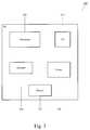
- FIG. 3shows components of a mobile unit used with the headset of FIG. 1 according to an exemplary embodiment of the present invention.
- FIG. 4shows an assembled system of components including the headset of FIG. 1 , the mobile unit of FIG. 3 and a module according to an exemplary embodiment of the present invention.
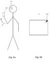
- FIG. 5 ashows a first movement of the mobile unit of FIG. 3 according to an exemplary embodiment of the present invention.
- FIG. 5 bshows a first translation of the first movement of FIG. 5 a on a head-mounted display according to an exemplary embodiment of the present invention.
- FIG. 6 ashows a second movement of the mobile unit of FIG. 3 according to an exemplary embodiment of the present invention.
- FIG. 6 bshows a second translation of the second movement of FIG. 6 a on a head-mounted display according to an exemplary embodiment of the present invention.
- FIG. 7 ashows a third movement subsequent to the second movement of FIG. 6 a of the mobile unit of FIG. 3 according to an exemplary embodiment of the present invention.
- FIG. 7 bshows a third translation of the third movement of FIG. 7 a on a head-mounted display according to an exemplary embodiment of the present invention.
- the exemplary embodiments of the present inventionmay be further understood with reference to the following description and the appended drawings, wherein like elements are referred to with the same reference numerals.
- the exemplary embodiments of the present inventiondescribe a user interface for a head-mounted display.
- the exemplary embodiments of the present inventionmay utilize a motion or inertial sensor disposed in the interface device to detect a motion that is translated into a movement of a pointing device shown on the display.
- the interface devicemay be embodied in a hand-held MU or an accessory thereto. The user interface, the head-mounted display, the sensor, the MU, and the accessory will be discussed in more detail below.
- FIG. 1shows a first view of a headset 100 according to an exemplary embodiment of the present invention.
- the headset 100may be any device capable of being worn on a user's head where components of the headset are used to perform a functionality.
- the headset 100may be for a voice functionality.
- the headset 100may also be configured to include additional functionalities such as displaying data to the user.
- the headset 100may be a stand alone unit or may be used in conjunction with other electronic devices.
- the headset 100may be coupled to an MU so that data may be exchanged between the headset 100 and the MU.
- the couplingmay be, for example, a wired connector from the headset 100 with a jack that plugs into a port of the MU.
- the headset 100may include a head band 105 , an audio output 110 , a stabilizer 115 , a boom 120 , an audio input 125 , an extender 130 , a head-mounted display 135 , and an input/output (I/O) port 140 .
- the head band 105may be a supporting mechanism to allow the headset 100 to be used hands-free.
- the head band 105may rest on a top surface of a user's head.
- the head band 105may be partially elastic so that the head band 105 may flex to conform to the top surface of the user's head.
- the head band 105may be manufactured, for example, of a semi-elastic polymer with a spring metal interior.
- the stabilizer 115may be a padding disposed at a first end of the head band 105 .
- the paddingmay provide a comfortable end to the head band 105 . Because the ends of the head band 105 partially squeeze (e.g., to securely hold the head set 100 on the user's head), the stabilizer 115 may allow the comfortable use of the headset 100 .
- the headset 100 including the head band 105 and the stabilizer 115is only exemplary.
- the headset 100may include an ear clip so that the headset 100 may be worn on a user's ear.
- the head band 105 and the stabilizer 115may be unnecessary.
- the audio output 110may be, for example, a speaker.
- the audio output 110may be disposed at a second end of the head band 105 .
- the audio output 110may include a cushion substantially similar to the stabilizer 115 . Again, because the ends of the head band 105 partially squeeze, the cushion of the audio output 110 may provide the comfortable wearing of the headset 100 .
- the audio output 110may be disposed around a user's ear.
- the stabilizer 115may be disposed slightly above a user's other ear.
- the boom 120may be a flexible extension where a first end of the boom 120 is attached to the second end of the head band 105 or the audio output 110 .
- a second end of the boom 120may be attached to the audio input 125 .
- the audio input 125may be, for example, a microphone.
- the flexibility of the boom 120may allow a user to orient the headset 100 so that the audio input 125 is disposed around a user's mouth.
- the audio input 125may include a foam coat so that sounds received by the audio input 125 may be filtered.
- the first end of the boom 120may be coupled to the second end of the head band 105 or the audio output 110 with a rotator. In this embodiment, the audio output 125 may be rotated in an upward position when not being used.
- the audio output 125may be deactivated, thereby conserving power.
- Voice data received by the audio input 125may include voice commands relating to the components of the headset 100 .
- the voice commandsmay activate/deactivate the head-mounted display 135 .
- the voice commandsmay relate to the MU.
- the extender 130may be another flexible extension where a first end of the extender 130 is attached to the head band 105 . As illustrated, the extender 130 is disposed on a right side of the head band 105 . However, it should be noted that the extender 130 may be disposed on a left side of the head band 105 above the audio output 110 , depending on a preference of the user. A second end of the extender 130 may be attached to the head-mounted display 135 . The flexibility of the extender 130 may allow the user to orient the head-mounted display 135 over an eye of the user. The head-mounted display 135 may be clear so that a user may view data thereon or view beyond the head-mounted display 135 . The head-mounted display 135 may also occlude.
- the first end of the extender 130may be coupled to the head band 105 with a rotator.
- the head-mounted display 135may be rotated in an upward position when not being used.
- the head-mounted display 135may be deactivated, thereby conserving power.
- the I/O port 140may be a device to connect the headset 100 to, for example, an MU.
- the I/O port 140may be configured to receive a connector from the MU. It should be noted that the use of the I/O port 140 is only exemplary.
- the headset 100may not include an actual I/O port 140 . Instead, the headset 100 may be equipped with a connector and a jack to be received by a port of the MU.
- the I/O port 140may also enable a wireless connection to be established with the MU. In the exemplary embodiment where a wireless connection is used, the headset 100 may include its own processor, memory, transceiver, antenna, etc.
- FIG. 2shows a second view of the headset 100 of FIG. 1 according to an exemplary embodiment of the present invention.
- the second viewillustrates an orientation of the audio output 110 , the audio input 125 , and the head-mounted display 135 when worn by the user.
- the audio output 110may be disposed around the user's ear.
- the audio input 125may be disposed around the user's mouth.
- the head-mounted display 135may be disposed around the user's eye.
- the audio output 110 and the head-mounted display 135are disposed to be worn on a right side of a user's face.
- FIG. 3shows components of an MU 200 used with the headset 100 of FIG. 1 according to an exemplary embodiment of the present invention.
- the MU 200may be any portable electronic device that utilizes a portable power supply (e.g., battery, capacitor, super capacitor, etc.).
- the MU 200may be a laptop, a personal digital assistant, a pager, a cell phone, a scanner, an RFID device, etc.
- the MU 200may include a processor 205 , a memory 210 , an input/output arrangement (I/O) 215 , a sensor 220 , and a battery 225 .
- I/Oinput/output arrangement
- the processor 205may be a central computing component that operates the MU 200 .
- the memory 210may store data related to the MU 200 .
- the datamay pertain to programs installed on the MU 200 , functionalities associated with the MU 200 , etc.
- the datamay also include configuration data relating to inputs received by the sensor 220 .
- the configuration datamay indicate how a pointing device of the head-mounted display 135 moves in accordance to the inputs.
- the battery 225may be a portable power supply that provides energy to the MU 200 .
- the MU 200may be any electronic device that utilizes a portable power supply.
- the battery 225may be a rechargeable battery such as a nickel cadmium (Ni—Cd), a nickel hydride (Ni—H), a lithium ion, etc. It should be noted that the battery 225 may be removed from the MU 200 . While removed, the battery 225 may be recharged separately from the MU 200 . The battery 225 may also provide energy to any accessory connected to the MU 200 including the headset 100 .
- the I/O 215may be connected to at least one port disposed on a periphery of the MU 200 .
- the I/O 215may be configured to establish an electrical connection between an accessory and the MU 200 .
- the headset 100may include a connector with a jack. The jack may be received in one of the ports of the MU 200 .
- the I/O 215may recognize the reception and establish the electrical connection between the MU 200 and the headset 100 .
- other accessoriesmay be connected to the MU 200 .
- the I/O 215may establish the electrical connection in other manners.
- the I/O 215may be a BlueTooth interface that wirelessly communicates with the I/O of the headset 100 .
- the headset 100may be wirelessly coupled to the MU 100 .
- the sensor 220may be a motion or inertial sensor that is configured to detect a direction that the MU 200 is moved and/or determine an angle or orientation that the MU 200 is positioned.
- the direction in which the MU 200 is movedmay be translated by the sensor 220 or the processor 205 into a corresponding movement of the pointing device on the head-mounted display 135 .
- the sensor 220may consist of, for example, an accelerometer. A user may activate the sensor 220 when requiring a user interface for the pointing device.
- Activationmay be achieved by various methods such as pressing a button, a voice command, a specific gesture recognized by the MU 200 through processing the data provided by the sensor 220 , etc. That is, a separate user interface such as a mouse, a stylus, etc. is not required to move the pointing device of the head-mounted display 135 .
- FIG. 4shows an assembled system of components including the headset 100 of FIG. 1 , the MU 200 of FIG. 3 and a module 300 according to an exemplary embodiment of the present invention.
- the headset 100may be electrically connected to the MU 200 .
- the headset 100may be equipped with a connector (extending from the port 140 ) that has a jack disposed on a distal end. The jack may be received by a port that is connected to the I/O 215 of the MU 200 .
- a module 300 or accessorymay be electrically connected to the MU 200 .
- the module 300may be connected to the MU 200 in a substantially similar manner as the headset 100 .
- the module 300may be any electronic device that provides an additional functionality.
- the module 300may be a data capture device such as a barcode scanner (e.g., one-dimensional, two-dimensional, color, etc.), a laser scanner, an imager, a camera, a radio frequency identification (RFID) reader, etc.
- the module 300may be a communications device such as a transceiver (if the MU 200 is not equipped with such a functionality).
- the module 300may be coupled to the MU 200 using any of the above described manners for coupling the MU 200 to the headset 100 such as a wired connection, a wireless connection, etc.
- the MU 200may be wearable. That is, the MU 200 may be coupled to a mount such as a wrist mount, a finger mount, a waist mount, etc.
- the module 300may also be wearable.
- the module 300may be a ring scanner that is worn on a finger.
- the MU 200 and the module 300may also be hand-held devices that are held in a user's hand.
- the module 300may be absent in the assembled system. That is, the module 300 may be an optional component that may be added to the system of the MU 200 and the headset 100 . Thus, the MU 200 may only be coupled to the headset 100 .
- the module 300may also include a processor, a memory, a battery, an I/O, and a sensor.
- the module 300does not include a memory or a battery as data may be stored in the memory 210 of the MU 200 and power may be provided by the battery 225 of the MU 200 .
- the I/O of the module 300may be coupled to the MU 200 .
- the processor of the module 300may be less complex than the processor 205 of the MU 200 as the processor of the module 300 need only execute the functionality provided thereby.
- the module 300may also include the sensor that is substantially similar to the sensor 220 of the MU 200 .
- the module sensormay provide the movement data that is translated into the corresponding movement of the pointing device of the head-mounted display 135 .
- the MU 200may not be equipped with the sensor 220 as it is redundant.
- the MU 200may be fixedly worn, for example, on a waist mount.
- the MU 200 and the module 300may be equipped with the sensor (not shown).
- the sensor of the module 300may be substantially similar to the sensor 220 of the MU 200 .
- the sensor of the module 300may override the sensor 220 of the MU 200 .
- the sensor 220may be deactivated while the sensor of the module 300 is activated.
- the type of mountmay determine activation or deactivation of the sensor.
- the MU 200may recognize that the MU 200 is likely to remain fixed in position. Thus, the MU 200 may deactivate the sensor 220 .
- the use of the module 300is only exemplary.
- the module 300may provide an additional functionality to the MU 200 .
- the MU 200may come equipped with the functionality provided by the module 300 .
- the module 300may represent providing a functionality that is not available to the MU 200 .
- FIG. 5 ashows a first movement of the MU 200 of FIG. 3 according to an exemplary embodiment of the present invention.
- the MU 200is hand-held, in particular, being held in a right hand of the user.
- the headset 100(not shown) is worn on the user's head with the head-mounted display 135 disposed over the user's right eye.
- the MU 200 and the headset 100may be coupled and the sensor 220 may be activated.
- the MU 200may be moved in any planar direction.
- the first movementinvolves moving the MU 200 down in the direction d 1 .
- the module 300may also include the sensor.
- the MU 200may be worn, while the module 300 is hand-held or worn, for example, on the user's wrist or finger.
- FIG. 5 bshows a first translation of the first movement of FIG. 5 a on the head-mounted display 135 according to an exemplary embodiment of the present invention.
- FIG. 5 bshows a view of how the user sees the head-mounted display 135 .
- the head-mounted display 135may include a pointing device 135 a.
- the first movement of FIG. 5 ais in the direction d 1 .
- the direction d 1is measured by the sensor 220 as going straight downward. Thus, this movement may be translated into a straight downward movement of the pointing device 135 a.
- FIG. 6 ashows a second movement of the MU 200 of FIG. 3 according to an exemplary embodiment of the present invention.
- the MU 200is hand-held, in particular, being held in a right hand of the user, while the headset 100 (not shown) is worn on the user's head with the head-mounted display 135 disposed over the user's right eye.
- the MU 200 and the headset 100may be electrically connected and the sensor 220 may be activated.
- the second movementinvolves moving the MU 200 upward and to the right in the direction d 2 .
- the use of the MU 200is only exemplary and the movement may be of the module 300 .
- FIG. 6 bshows a second translation of the second movement of FIG. 6 a on the head-mounted display 135 according to an exemplary embodiment of the present invention.
- FIG. 6 bshows a view of how the user sees the head-mounted display 135 .
- the head-mounted display 135may include the pointing device 135 a .
- the second movement of FIG. 6 ais in the direction d 2 .
- the direction d 2is measured by the sensor 220 as going upward and to the right. Thus, this movement may be translated into an upward and to the right movement of the pointing device 135 a.
- FIG. 7 ashows a third movement subsequent to the second movement of FIG. 6 a of the MU 200 of FIG. 3 according to an exemplary embodiment of the present invention.
- the third movementrelates to moving the MU 200 upon moving the MU 200 in the direction d 2 .
- the third movementinvolves moving the MU 200 down in the direction d 3 .
- FIG. 7 bshows a third translation of the third movement of FIG. 7 a on the head-mounted display 135 according to an exemplary embodiment of the present invention.
- FIG. 7 bshows a view of how the user sees the head-mounted display 135 .
- the pointing device 135 a ′was originally located in an upper right corner of the head-mounted display 135 .
- the third movement of FIG. 6 ais in the direction d 3 .
- the direction d 3is measured by the sensor 220 as going straight downward. Thus, this movement may be translated into a downward movement of the pointing device 135 a from the position last seen in FIG. 6 b.
- the exemplary embodiments of the present inventionenable a user to utilize a pointing device for a head-mounted display without requiring a use of both hands of the user.
- a touch pad or stylusmay be necessary to move the pointing device.
- one handmay hold the MU while the other hand uses the interface to move the pointing device.
- the sensor disposed in the MU and/or the module of the exemplary embodimentsallow the pointing device to be moved with a single hand. As discussed above, a movement of the MU or the module itself translates into the movement of the pointing device.
- the exemplary embodiments of the present inventionalso enable a user to utilize a pointing device for a head-mounted display without requiring the user to move the user's head. For example, if the MU is hand-held, a touch pad or stylus may be necessary to move the pointing device. In each of these cases, the user is required to look down at the MU in order to use the pointing device. With the sensor integrated in the MU 200 or module 300 , the user does not need to look away from the head-mounted display.
Landscapes
- Engineering & Computer Science (AREA)
- Theoretical Computer Science (AREA)
- General Engineering & Computer Science (AREA)
- Human Computer Interaction (AREA)
- Physics & Mathematics (AREA)
- General Physics & Mathematics (AREA)
- Computer Hardware Design (AREA)
- Position Input By Displaying (AREA)
Abstract
Description
Claims (22)
Priority Applications (2)
| Application Number | Priority Date | Filing Date | Title |
|---|---|---|---|
| US11/940,546US8072393B2 (en) | 2007-11-15 | 2007-11-15 | User interface for a head mounted display |
| US13/221,941US8681074B2 (en) | 2007-11-15 | 2011-08-31 | User interface for a head mounted display |
Applications Claiming Priority (1)
| Application Number | Priority Date | Filing Date | Title |
|---|---|---|---|
| US11/940,546US8072393B2 (en) | 2007-11-15 | 2007-11-15 | User interface for a head mounted display |
Related Child Applications (1)
| Application Number | Title | Priority Date | Filing Date |
|---|---|---|---|
| US13/221,941ContinuationUS8681074B2 (en) | 2007-11-15 | 2011-08-31 | User interface for a head mounted display |
Publications (2)
| Publication Number | Publication Date |
|---|---|
| US20090128448A1 US20090128448A1 (en) | 2009-05-21 |
| US8072393B2true US8072393B2 (en) | 2011-12-06 |
Family
ID=40641391
Family Applications (2)
| Application Number | Title | Priority Date | Filing Date |
|---|---|---|---|
| US11/940,546Active2030-10-02US8072393B2 (en) | 2007-11-15 | 2007-11-15 | User interface for a head mounted display |
| US13/221,941Active2028-02-12US8681074B2 (en) | 2007-11-15 | 2011-08-31 | User interface for a head mounted display |
Family Applications After (1)
| Application Number | Title | Priority Date | Filing Date |
|---|---|---|---|
| US13/221,941Active2028-02-12US8681074B2 (en) | 2007-11-15 | 2011-08-31 | User interface for a head mounted display |
Country Status (1)
| Country | Link |
|---|---|
| US (2) | US8072393B2 (en) |
Cited By (28)
| Publication number | Priority date | Publication date | Assignee | Title |
|---|---|---|---|---|
| US20080169998A1 (en)* | 2007-01-12 | 2008-07-17 | Kopin Corporation | Monocular display device |
| US20110089207A1 (en)* | 2009-10-21 | 2011-04-21 | Symbol Technologies, Inc. | Mounting device couplable to a human head |
| US20110194029A1 (en)* | 2010-02-05 | 2011-08-11 | Kopin Corporation | Touch sensor for controlling eyewear |
| US8355671B2 (en) | 2008-01-04 | 2013-01-15 | Kopin Corporation | Method and apparatus for transporting video signal over Bluetooth wireless interface |
| US8378924B2 (en) | 2007-01-12 | 2013-02-19 | Kopin Corporation | Monocular display device |
| US8706170B2 (en) | 2010-09-20 | 2014-04-22 | Kopin Corporation | Miniature communications gateway for head mounted display |
| US8736516B2 (en) | 2010-09-20 | 2014-05-27 | Kopin Corporation | Bluetooth or other wireless interface with power management for head mounted display |
| US8825468B2 (en) | 2007-07-31 | 2014-09-02 | Kopin Corporation | Mobile wireless display providing speech to speech translation and avatar simulating human attributes |
| USD713406S1 (en) | 2012-11-30 | 2014-09-16 | Kopin Corporation | Headset computer with reversible display |
| US8929954B2 (en) | 2012-04-25 | 2015-01-06 | Kopin Corporation | Headset computer (HSC) as auxiliary display with ASR and HT input |
| USD724084S1 (en)* | 2014-03-17 | 2015-03-10 | Lg Electronics Inc. | Head mounted display device |
| US8994610B2 (en) | 2010-11-08 | 2015-03-31 | Symbol Technologies, Inc. | User configurable headset |
| US9116340B2 (en) | 2007-05-14 | 2015-08-25 | Kopin Corporation | Mobile wireless display for accessing data from a host and method for controlling |
| US9134793B2 (en) | 2013-01-04 | 2015-09-15 | Kopin Corporation | Headset computer with head tracking input used for inertial control |
| US9160064B2 (en) | 2012-12-28 | 2015-10-13 | Kopin Corporation | Spatially diverse antennas for a headset computer |
| US9201625B2 (en) | 2012-06-22 | 2015-12-01 | Nokia Technologies Oy | Method and apparatus for augmenting an index generated by a near eye display |
| US9332580B2 (en) | 2013-01-04 | 2016-05-03 | Kopin Corporation | Methods and apparatus for forming ad-hoc networks among headset computers sharing an identifier |
| US9377862B2 (en) | 2010-09-20 | 2016-06-28 | Kopin Corporation | Searchlight navigation using headtracker to reveal hidden or extra document data |
| US9378028B2 (en) | 2012-05-31 | 2016-06-28 | Kopin Corporation | Headset computer (HSC) with docking station and dual personality |
| US9442290B2 (en) | 2012-05-10 | 2016-09-13 | Kopin Corporation | Headset computer operation using vehicle sensor feedback for remote control vehicle |
| US9620144B2 (en) | 2013-01-04 | 2017-04-11 | Kopin Corporation | Confirmation of speech commands for control of headset computers |
| US9817232B2 (en) | 2010-09-20 | 2017-11-14 | Kopin Corporation | Head movement controlled navigation among multiple boards for display in a headset computer |
| US9886231B2 (en) | 2008-03-28 | 2018-02-06 | Kopin Corporation | Head worn wireless computer having high-resolution display suitable for use as a mobile internet device |
| US9910501B2 (en) | 2014-01-07 | 2018-03-06 | Toshiba Global Commerce Solutions Holdings Corporation | Systems and methods for implementing retail processes based on machine-readable images and user gestures |
| US10013976B2 (en) | 2010-09-20 | 2018-07-03 | Kopin Corporation | Context sensitive overlays in voice controlled headset computer displays |
| US10019149B2 (en) | 2014-01-07 | 2018-07-10 | Toshiba Global Commerce Solutions Holdings Corporation | Systems and methods for implementing retail processes based on machine-readable images and user gestures |
| US10627860B2 (en) | 2011-05-10 | 2020-04-21 | Kopin Corporation | Headset computer that uses motion and voice commands to control information display and remote devices |
| USD945521S1 (en) | 2016-06-21 | 2022-03-08 | Symbol Technologies, Llc | Heads-up display mount |
Families Citing this family (33)
| Publication number | Priority date | Publication date | Assignee | Title |
|---|---|---|---|---|
| US7841967B1 (en) | 2006-04-26 | 2010-11-30 | Dp Technologies, Inc. | Method and apparatus for providing fitness coaching using a mobile device |
| US8902154B1 (en) | 2006-07-11 | 2014-12-02 | Dp Technologies, Inc. | Method and apparatus for utilizing motion user interface |
| US8620353B1 (en) | 2007-01-26 | 2013-12-31 | Dp Technologies, Inc. | Automatic sharing and publication of multimedia from a mobile device |
| US8949070B1 (en) | 2007-02-08 | 2015-02-03 | Dp Technologies, Inc. | Human activity monitoring device with activity identification |
| US8855719B2 (en)* | 2009-05-08 | 2014-10-07 | Kopin Corporation | Wireless hands-free computing headset with detachable accessories controllable by motion, body gesture and/or vocal commands |
| US8555282B1 (en) | 2007-07-27 | 2013-10-08 | Dp Technologies, Inc. | Optimizing preemptive operating system with motion sensing |
| US20090262205A1 (en)* | 2008-04-21 | 2009-10-22 | Dana Stephen Smith | Voice activated headset imaging system |
| US8285344B2 (en) | 2008-05-21 | 2012-10-09 | DP Technlogies, Inc. | Method and apparatus for adjusting audio for a user environment |
| US8996332B2 (en) | 2008-06-24 | 2015-03-31 | Dp Technologies, Inc. | Program setting adjustments based on activity identification |
| US8957835B2 (en) | 2008-09-30 | 2015-02-17 | Apple Inc. | Head-mounted display apparatus for retaining a portable electronic device with display |
| US8872646B2 (en) | 2008-10-08 | 2014-10-28 | Dp Technologies, Inc. | Method and system for waking up a device due to motion |
| US8624836B1 (en)* | 2008-10-24 | 2014-01-07 | Google Inc. | Gesture-based small device input |
| WO2010129679A1 (en) | 2009-05-08 | 2010-11-11 | Kopin Corporation | Remote control of host application using motion and voice commands |
| US9529437B2 (en)* | 2009-05-26 | 2016-12-27 | Dp Technologies, Inc. | Method and apparatus for a motion state aware device |
| US10462651B1 (en)* | 2010-05-18 | 2019-10-29 | Electric Mirror, Llc | Apparatuses and methods for streaming audio and video |
| US9686673B2 (en)* | 2010-05-18 | 2017-06-20 | Electric Mirror, Llc | Apparatuses and methods for streaming audio and video |
| US8862186B2 (en) | 2010-09-21 | 2014-10-14 | Kopin Corporation | Lapel microphone micro-display system incorporating mobile information access system |
| US20180048750A1 (en)* | 2012-06-15 | 2018-02-15 | Muzik, Llc | Audio/video wearable computer system with integrated projector |
| US20130339859A1 (en) | 2012-06-15 | 2013-12-19 | Muzik LLC | Interactive networked headphones |
| US9874936B2 (en)* | 2012-06-22 | 2018-01-23 | Cape Evolution Limited | Wearable electronic device |
| US9301085B2 (en) | 2013-02-20 | 2016-03-29 | Kopin Corporation | Computer headset with detachable 4G radio |
| US8922366B1 (en) | 2013-06-28 | 2014-12-30 | Google Inc. | Reader communication with contact lens sensors and display device |
| KR102229890B1 (en)* | 2014-05-30 | 2021-03-19 | 삼성전자주식회사 | Method for processing data and an electronic device thereof |
| GB2543019A (en)* | 2015-07-23 | 2017-04-12 | Muzaffar Saj | Virtual reality headset user input system |
| US9298283B1 (en) | 2015-09-10 | 2016-03-29 | Connectivity Labs Inc. | Sedentary virtual reality method and systems |
| US9996149B1 (en) | 2016-02-22 | 2018-06-12 | Immersacad Corporation | Method for one-touch translational navigation of immersive, virtual reality environments |
| US10936872B2 (en) | 2016-12-23 | 2021-03-02 | Realwear, Inc. | Hands-free contextually aware object interaction for wearable display |
| US10620910B2 (en)* | 2016-12-23 | 2020-04-14 | Realwear, Inc. | Hands-free navigation of touch-based operating systems |
| US10437070B2 (en) | 2016-12-23 | 2019-10-08 | Realwear, Inc. | Interchangeable optics for a head-mounted display |
| US10393312B2 (en) | 2016-12-23 | 2019-08-27 | Realwear, Inc. | Articulating components for a head-mounted display |
| US11099716B2 (en) | 2016-12-23 | 2021-08-24 | Realwear, Inc. | Context based content navigation for wearable display |
| US11507216B2 (en) | 2016-12-23 | 2022-11-22 | Realwear, Inc. | Customizing user interfaces of binary applications |
| CN110134197A (en)* | 2019-06-26 | 2019-08-16 | 北京小米移动软件有限公司 | Wearable control device, virtual/augmented reality system and control method |
Citations (11)
| Publication number | Priority date | Publication date | Assignee | Title |
|---|---|---|---|---|
| US5590062A (en)* | 1993-07-02 | 1996-12-31 | Matsushita Electric Industrial Co., Ltd. | Simulator for producing various living environments mainly for visual perception |
| US5844824A (en) | 1995-10-02 | 1998-12-01 | Xybernaut Corporation | Hands-free, portable computer and system |
| US6127990A (en) | 1995-11-28 | 2000-10-03 | Vega Vista, Inc. | Wearable display and methods for controlling same |
| US6167413A (en)* | 2000-03-09 | 2000-12-26 | Daley, Iii; Charles A. | Wearable computer apparatus |
| US6347290B1 (en) | 1998-06-24 | 2002-02-12 | Compaq Information Technologies Group, L.P. | Apparatus and method for detecting and executing positional and gesture commands corresponding to movement of handheld computing device |
| US6573883B1 (en) | 1998-06-24 | 2003-06-03 | Hewlett Packard Development Company, L.P. | Method and apparatus for controlling a computing device with gestures |
| US6798429B2 (en) | 2001-03-29 | 2004-09-28 | Intel Corporation | Intuitive mobile device interface to virtual spaces |
| US6853293B2 (en) | 1993-05-28 | 2005-02-08 | Symbol Technologies, Inc. | Wearable communication system |
| US6985138B2 (en)* | 2003-08-29 | 2006-01-10 | Motorola, Inc. | Input writing device |
| US20060164230A1 (en)* | 2000-03-02 | 2006-07-27 | Dewind Darryl P | Interior mirror assembly with display |
| US20080246694A1 (en)* | 2007-04-06 | 2008-10-09 | Ronald Fischer | Personal theater display |
Family Cites Families (1)
| Publication number | Priority date | Publication date | Assignee | Title |
|---|---|---|---|---|
| JP4642400B2 (en)* | 2004-07-20 | 2011-03-02 | オリンパス株式会社 | Information display system |
- 2007
- 2007-11-15USUS11/940,546patent/US8072393B2/enactiveActive
- 2011
- 2011-08-31USUS13/221,941patent/US8681074B2/enactiveActive
Patent Citations (11)
| Publication number | Priority date | Publication date | Assignee | Title |
|---|---|---|---|---|
| US6853293B2 (en) | 1993-05-28 | 2005-02-08 | Symbol Technologies, Inc. | Wearable communication system |
| US5590062A (en)* | 1993-07-02 | 1996-12-31 | Matsushita Electric Industrial Co., Ltd. | Simulator for producing various living environments mainly for visual perception |
| US5844824A (en) | 1995-10-02 | 1998-12-01 | Xybernaut Corporation | Hands-free, portable computer and system |
| US6127990A (en) | 1995-11-28 | 2000-10-03 | Vega Vista, Inc. | Wearable display and methods for controlling same |
| US6347290B1 (en) | 1998-06-24 | 2002-02-12 | Compaq Information Technologies Group, L.P. | Apparatus and method for detecting and executing positional and gesture commands corresponding to movement of handheld computing device |
| US6573883B1 (en) | 1998-06-24 | 2003-06-03 | Hewlett Packard Development Company, L.P. | Method and apparatus for controlling a computing device with gestures |
| US20060164230A1 (en)* | 2000-03-02 | 2006-07-27 | Dewind Darryl P | Interior mirror assembly with display |
| US6167413A (en)* | 2000-03-09 | 2000-12-26 | Daley, Iii; Charles A. | Wearable computer apparatus |
| US6798429B2 (en) | 2001-03-29 | 2004-09-28 | Intel Corporation | Intuitive mobile device interface to virtual spaces |
| US6985138B2 (en)* | 2003-08-29 | 2006-01-10 | Motorola, Inc. | Input writing device |
| US20080246694A1 (en)* | 2007-04-06 | 2008-10-09 | Ronald Fischer | Personal theater display |
Cited By (38)
| Publication number | Priority date | Publication date | Assignee | Title |
|---|---|---|---|---|
| US9217868B2 (en) | 2007-01-12 | 2015-12-22 | Kopin Corporation | Monocular display device |
| US20080169998A1 (en)* | 2007-01-12 | 2008-07-17 | Kopin Corporation | Monocular display device |
| US8378924B2 (en) | 2007-01-12 | 2013-02-19 | Kopin Corporation | Monocular display device |
| US9116340B2 (en) | 2007-05-14 | 2015-08-25 | Kopin Corporation | Mobile wireless display for accessing data from a host and method for controlling |
| US9310613B2 (en) | 2007-05-14 | 2016-04-12 | Kopin Corporation | Mobile wireless display for accessing data from a host and method for controlling |
| US8825468B2 (en) | 2007-07-31 | 2014-09-02 | Kopin Corporation | Mobile wireless display providing speech to speech translation and avatar simulating human attributes |
| US10579324B2 (en) | 2008-01-04 | 2020-03-03 | BlueRadios, Inc. | Head worn wireless computer having high-resolution display suitable for use as a mobile internet device |
| US10474418B2 (en) | 2008-01-04 | 2019-11-12 | BlueRadios, Inc. | Head worn wireless computer having high-resolution display suitable for use as a mobile internet device |
| US8355671B2 (en) | 2008-01-04 | 2013-01-15 | Kopin Corporation | Method and apparatus for transporting video signal over Bluetooth wireless interface |
| US9886231B2 (en) | 2008-03-28 | 2018-02-06 | Kopin Corporation | Head worn wireless computer having high-resolution display suitable for use as a mobile internet device |
| US9503555B2 (en) | 2009-10-21 | 2016-11-22 | Symbol Technologies, Llc | Mounting device couplable to a human head |
| US20110089207A1 (en)* | 2009-10-21 | 2011-04-21 | Symbol Technologies, Inc. | Mounting device couplable to a human head |
| US8665177B2 (en) | 2010-02-05 | 2014-03-04 | Kopin Corporation | Touch sensor for controlling eyewear |
| US20110194029A1 (en)* | 2010-02-05 | 2011-08-11 | Kopin Corporation | Touch sensor for controlling eyewear |
| US9817232B2 (en) | 2010-09-20 | 2017-11-14 | Kopin Corporation | Head movement controlled navigation among multiple boards for display in a headset computer |
| US9152378B2 (en) | 2010-09-20 | 2015-10-06 | Kopin Corporation | Bluetooth or other wireless interface with power management for head mounted display |
| US8706170B2 (en) | 2010-09-20 | 2014-04-22 | Kopin Corporation | Miniature communications gateway for head mounted display |
| US8736516B2 (en) | 2010-09-20 | 2014-05-27 | Kopin Corporation | Bluetooth or other wireless interface with power management for head mounted display |
| US10013976B2 (en) | 2010-09-20 | 2018-07-03 | Kopin Corporation | Context sensitive overlays in voice controlled headset computer displays |
| US9377862B2 (en) | 2010-09-20 | 2016-06-28 | Kopin Corporation | Searchlight navigation using headtracker to reveal hidden or extra document data |
| US8994610B2 (en) | 2010-11-08 | 2015-03-31 | Symbol Technologies, Inc. | User configurable headset |
| US11237594B2 (en) | 2011-05-10 | 2022-02-01 | Kopin Corporation | Headset computer that uses motion and voice commands to control information display and remote devices |
| US10627860B2 (en) | 2011-05-10 | 2020-04-21 | Kopin Corporation | Headset computer that uses motion and voice commands to control information display and remote devices |
| US11947387B2 (en) | 2011-05-10 | 2024-04-02 | Kopin Corporation | Headset computer that uses motion and voice commands to control information display and remote devices |
| US8929954B2 (en) | 2012-04-25 | 2015-01-06 | Kopin Corporation | Headset computer (HSC) as auxiliary display with ASR and HT input |
| US9294607B2 (en) | 2012-04-25 | 2016-03-22 | Kopin Corporation | Headset computer (HSC) as auxiliary display with ASR and HT input |
| US9442290B2 (en) | 2012-05-10 | 2016-09-13 | Kopin Corporation | Headset computer operation using vehicle sensor feedback for remote control vehicle |
| US9378028B2 (en) | 2012-05-31 | 2016-06-28 | Kopin Corporation | Headset computer (HSC) with docking station and dual personality |
| US9201625B2 (en) | 2012-06-22 | 2015-12-01 | Nokia Technologies Oy | Method and apparatus for augmenting an index generated by a near eye display |
| USD713406S1 (en) | 2012-11-30 | 2014-09-16 | Kopin Corporation | Headset computer with reversible display |
| US9160064B2 (en) | 2012-12-28 | 2015-10-13 | Kopin Corporation | Spatially diverse antennas for a headset computer |
| US9620144B2 (en) | 2013-01-04 | 2017-04-11 | Kopin Corporation | Confirmation of speech commands for control of headset computers |
| US9332580B2 (en) | 2013-01-04 | 2016-05-03 | Kopin Corporation | Methods and apparatus for forming ad-hoc networks among headset computers sharing an identifier |
| US9134793B2 (en) | 2013-01-04 | 2015-09-15 | Kopin Corporation | Headset computer with head tracking input used for inertial control |
| US9910501B2 (en) | 2014-01-07 | 2018-03-06 | Toshiba Global Commerce Solutions Holdings Corporation | Systems and methods for implementing retail processes based on machine-readable images and user gestures |
| US10019149B2 (en) | 2014-01-07 | 2018-07-10 | Toshiba Global Commerce Solutions Holdings Corporation | Systems and methods for implementing retail processes based on machine-readable images and user gestures |
| USD724084S1 (en)* | 2014-03-17 | 2015-03-10 | Lg Electronics Inc. | Head mounted display device |
| USD945521S1 (en) | 2016-06-21 | 2022-03-08 | Symbol Technologies, Llc | Heads-up display mount |
Also Published As
| Publication number | Publication date |
|---|---|
| US8681074B2 (en) | 2014-03-25 |
| US20090128448A1 (en) | 2009-05-21 |
| US20110310012A1 (en) | 2011-12-22 |
Similar Documents
| Publication | Publication Date | Title |
|---|---|---|
| US8072393B2 (en) | User interface for a head mounted display | |
| US8520860B2 (en) | Modular mobile computing headset | |
| CN107786922B (en) | Portable sound equipment | |
| US12045395B2 (en) | Wearable device and method for detecting motion gesture of wearable device | |
| US9668367B2 (en) | Wearable computing systems | |
| US20080054039A1 (en) | Wearable Mobile Computing System | |
| EP3300386A1 (en) | Bluetooth headset and watch including same | |
| KR20190018518A (en) | Wearable device | |
| CN103324309A (en) | Wearable computer | |
| US11990689B2 (en) | Antenna system for wearable devices | |
| EP3102993A1 (en) | Wearable computing device | |
| KR20220016734A (en) | Electronic device controlling input mode according to folding angle and Method thereof | |
| CN109892755A (en) | A kind of watch chain and wearable device | |
| KR20200133456A (en) | Wearable electronic device including force sensor | |
| WO2015187054A1 (en) | Wearable electronic communication device | |
| KR100703323B1 (en) | Headset | |
| KR20160032563A (en) | Terminal of watch type and mobile terminal assembly | |
| KR20170072769A (en) | Bluetooth headset and wristwatch comprising the same | |
| US20220407220A1 (en) | Tunable monopole antenna with unified grounding structure | |
| CN212435844U (en) | AR glasses control device and MR glasses system with same | |
| CN210143969U (en) | Watch chain and wearable device | |
| US20230327328A1 (en) | Antenna system for mobile devices | |
| CN212543998U (en) | Portable bluetooth sound of gesture control | |
| CN110133993A (en) | wearable smart watch | |
| EP4378348A1 (en) | Cover of electronic device |
Legal Events
| Date | Code | Title | Description |
|---|---|---|---|
| AS | Assignment | Owner name:SYMBOL TECHNOLOGIES, INC., NEW YORK Free format text:ASSIGNMENT OF ASSIGNORS INTEREST;ASSIGNOR:RIECHEL, PATRICK;REEL/FRAME:020161/0239 Effective date:20071114 | |
| STCF | Information on status: patent grant | Free format text:PATENTED CASE | |
| AS | Assignment | Owner name:MORGAN STANLEY SENIOR FUNDING, INC. AS THE COLLATERAL AGENT, MARYLAND Free format text:SECURITY AGREEMENT;ASSIGNORS:ZIH CORP.;LASER BAND, LLC;ZEBRA ENTERPRISE SOLUTIONS CORP.;AND OTHERS;REEL/FRAME:034114/0270 Effective date:20141027 Owner name:MORGAN STANLEY SENIOR FUNDING, INC. AS THE COLLATE Free format text:SECURITY AGREEMENT;ASSIGNORS:ZIH CORP.;LASER BAND, LLC;ZEBRA ENTERPRISE SOLUTIONS CORP.;AND OTHERS;REEL/FRAME:034114/0270 Effective date:20141027 | |
| FPAY | Fee payment | Year of fee payment:4 | |
| AS | Assignment | Owner name:SYMBOL TECHNOLOGIES, LLC, NEW YORK Free format text:CHANGE OF NAME;ASSIGNOR:SYMBOL TECHNOLOGIES, INC.;REEL/FRAME:036083/0640 Effective date:20150410 | |
| AS | Assignment | Owner name:SYMBOL TECHNOLOGIES, INC., NEW YORK Free format text:RELEASE BY SECURED PARTY;ASSIGNOR:MORGAN STANLEY SENIOR FUNDING, INC.;REEL/FRAME:036371/0738 Effective date:20150721 | |
| MAFP | Maintenance fee payment | Free format text:PAYMENT OF MAINTENANCE FEE, 8TH YEAR, LARGE ENTITY (ORIGINAL EVENT CODE: M1552); ENTITY STATUS OF PATENT OWNER: LARGE ENTITY Year of fee payment:8 | |
| MAFP | Maintenance fee payment | Free format text:PAYMENT OF MAINTENANCE FEE, 12TH YEAR, LARGE ENTITY (ORIGINAL EVENT CODE: M1553); ENTITY STATUS OF PATENT OWNER: LARGE ENTITY Year of fee payment:12 |