US8071922B2 - Impingement/convection/microwave oven and method - Google Patents
Impingement/convection/microwave oven and methodDownload PDFInfo
- Publication number
- US8071922B2 US8071922B2US11/302,638US30263805AUS8071922B2US 8071922 B2US8071922 B2US 8071922B2US 30263805 AUS30263805 AUS 30263805AUS 8071922 B2US8071922 B2US 8071922B2
- Authority
- US
- United States
- Prior art keywords
- oven
- impingement
- oven chamber
- air
- wall
- Prior art date
- Legal status (The legal status is an assumption and is not a legal conclusion. Google has not performed a legal analysis and makes no representation as to the accuracy of the status listed.)
- Expired - Fee Related
Links
Images


Classifications
- H—ELECTRICITY
- H05—ELECTRIC TECHNIQUES NOT OTHERWISE PROVIDED FOR
- H05B—ELECTRIC HEATING; ELECTRIC LIGHT SOURCES NOT OTHERWISE PROVIDED FOR; CIRCUIT ARRANGEMENTS FOR ELECTRIC LIGHT SOURCES, IN GENERAL
- H05B6/00—Heating by electric, magnetic or electromagnetic fields
- H05B6/64—Heating using microwaves
- A—HUMAN NECESSITIES
- A21—BAKING; EDIBLE DOUGHS
- A21B—BAKERS' OVENS; MACHINES OR EQUIPMENT FOR BAKING
- A21B1/00—Bakers' ovens
- A21B1/02—Bakers' ovens characterised by the heating arrangements
- A21B1/24—Ovens heated by media flowing therethrough
- A21B1/245—Ovens heated by media flowing therethrough with a plurality of air nozzles to obtain an impingement effect on the food
- H—ELECTRICITY
- H05—ELECTRIC TECHNIQUES NOT OTHERWISE PROVIDED FOR
- H05B—ELECTRIC HEATING; ELECTRIC LIGHT SOURCES NOT OTHERWISE PROVIDED FOR; CIRCUIT ARRANGEMENTS FOR ELECTRIC LIGHT SOURCES, IN GENERAL
- H05B6/00—Heating by electric, magnetic or electromagnetic fields
- H05B6/64—Heating using microwaves
- H05B6/642—Cooling of the microwave components and related air circulation systems
- H—ELECTRICITY
- H05—ELECTRIC TECHNIQUES NOT OTHERWISE PROVIDED FOR
- H05B—ELECTRIC HEATING; ELECTRIC LIGHT SOURCES NOT OTHERWISE PROVIDED FOR; CIRCUIT ARRANGEMENTS FOR ELECTRIC LIGHT SOURCES, IN GENERAL
- H05B6/00—Heating by electric, magnetic or electromagnetic fields
- H05B6/64—Heating using microwaves
- H05B6/6426—Aspects relating to the exterior of the microwave heating apparatus, e.g. metal casing, power cord
- H—ELECTRICITY
- H05—ELECTRIC TECHNIQUES NOT OTHERWISE PROVIDED FOR
- H05B—ELECTRIC HEATING; ELECTRIC LIGHT SOURCES NOT OTHERWISE PROVIDED FOR; CIRCUIT ARRANGEMENTS FOR ELECTRIC LIGHT SOURCES, IN GENERAL
- H05B6/00—Heating by electric, magnetic or electromagnetic fields
- H05B6/64—Heating using microwaves
- H05B6/647—Aspects related to microwave heating combined with other heating techniques
- H05B6/6473—Aspects related to microwave heating combined with other heating techniques combined with convection heating
- H05B6/6476—Aspects related to microwave heating combined with other heating techniques combined with convection heating the refrigerating air being used for convection
Definitions
- This inventionrelates to new and improved cooking ovens, systems, oven controllers and methods concerning microwave, convection and impingement cooking separately and in various combinations as well as cooling and interlock features for cooking ovens in general.
- a cooking oven that has both convection and impingement modesis shown in U.S. Pat. No. 5,345,923 as a countertop oven with one or more removable air impingement supply structures.
- Each air impingement supply structureincludes a specially designed food rack disposed between upper and lower corrugated impingement air forming walls.
- the air impingement supply structuresare removably inserted into the oven's air impingement supply structure cooking chamber for operation in the impingement mode.
- One or more of the air impingement supply structurescan be removed and replaced by a standard food rack for operation in a convection mode.
- the countertop ovenrequires n specially designed food racks for n air impingement supply structures and up to n standard food racks.
- the countertop ovenalso uses a fan disposed adjacent a side wall of the oven chamber, which increases the side-to-side footprint of the oven.
- a cooking oven that has both a microwave mode and an impingement modeis shown in U.S. Pat. No. 5,254,823 as an oven that has a rather large preheated thermal reservoir (at least 60 pounds) so as to facilitate rapid heat transfer to ambient air in a plenum.
- a rather large preheated thermal reservoirat least 60 pounds
- the preheat timeis considerable (up to two or more hours) and cooling of the oven's exterior surfaces can be difficult and energy inefficient.
- the ovenuses impingement air from a top of the oven's cooking chamber.
- the ovenhas a single microwave energy feed into the bottom of the cooking chamber. This results in uneven microwave cooking as the bottom of the food product is exposed to direct microwave energy and the top of the food is exposed to indirect microwave energy. Moreover, if metal pans are used, bottom feed microwave energy results in a large amount of reflected microwave energy to the bottom feed aperture, which can considerably reduce the useful life of the magnetrons.
- a combination oven of the present inventioncomprises an oven chamber and at least one impingement air generator disposed in the oven chamber to provide impingement air that flows substantially in a vertical direction within the oven chamber.
- a microwave generatoris disposed to provide microwave energy into the oven chamber via at least one wall of the oven chamber.
- a controlleroperates the oven in a microwave mode, an impingement mode or a combination microwave and impingement mode.
- the wallis vertical.
- the wallis a back wall or a side wall.
- the microwave generatorprovides the microwave energy via two walls of the oven chamber.
- the impingement air generatorcomprises a removable plate, a blower and an air heater.
- the wallis a side wall and the oven further comprises a fan disposed in a fan box to circulate heated air between the fan box and the oven chamber via a baffle plate.
- the impingement air generatorcomprises a plate that converts a portion of the circulating air to the impingement air.
- the plateis removable to convert the oven for operation in either a convection mode or a combination microwave and convection mode.
- the plateis disposed near a bottom wall of the oven chamber so that the impingement air flows upwardly.
- the plateis disposed near a top wall of the oven chamber so that the impingement air flows downwardly.
- an additional plateis disposed near a top wall of the oven chamber so that another portion of the impingement air flows downwardly.
- the platehas a handle to facilitate installation and removal by a sliding motion.
- the platecomprises a front and opposed sides separated by a wall that contains an array of jet holes shaped to provide the impingement air.
- the plateis installable in and removable from the oven chamber.
- the plateis installed substantially flush with the baffle plate to receive circulating air from the fan box.
- the platecomprises a diverter to provide a substantially uniform pressure to the jet holes, whether located near or remote from the baffle plate.
- the microwave generatoralso provides microwave energy into the oven chamber via an opposite side wall of the oven chamber.
- the microwave generatorcomprises one or more magnetrons and one or more wave guides to provide the microwave energy.
- the ovencomprises an outer enclosure comprising at least a first side wall and an additional wall that is substantially perpendicular to the first side wall and connected to the first side wall by a portion that is inwardly offset from the first side wall.
- An inner enclosureis disposed within and spaced from the outer enclosure by a passageway.
- a cooling fanis disposed within the passageway and is operable to maintain a flow of cooling air in the passageway between at least one intake port and one or more output ports.
- the intake portis located in the offset portion of the outer enclosure.
- the outer enclosurefurther comprises a second side wall.
- the additional wallis inwardly offset from the second side wall by an additional offset portion.
- An additional intake portis located in the additional offset portion.
- the offset portioncomprises a first bevel between the additional wall and the first side wall, and wherein the additional offset portion comprises a second bevel between the additional wall and the second side wall.
- the additional wallis a bottom wall.
- the output portis located in a back wall of the outer enclosure.
- an air filterdisposed at the intake port.
- a first air filteris disposed in the intake port and a second air filter is disposed at the second intake port.
- a first air filter holder and a second air filter holderthat enables easy installation and removal of the first air filter and the second air filter, respectively, are provided.
- the first air filter holder and the second air filter holderare configured for installation and removal by a sliding motion of the respective air filters.
- a source of cooking energyis disposed to provide cook energy to the inner enclosure to cook food therein.
- a method of the present inventionoperates an oven that includes an oven chamber.
- the methodcomprises:
- controlling the ovensuch that it operates in either a microwave mode, an impingement mode or a combination microwave and impingement mode.
- the wallis vertical.
- the wallis a back wall or a side wall.
- the microwave energyis provided by a microwave generator via two walls of the oven chamber.
- a further stepcomprises installing in and removing from the oven chamber a removable impingement plate.
- the impingement plateis installable in and removable from the oven chamber with a sliding motion.
- the wallis a side wall and further steps comprise running a fan disposed in a fan box to circulate heated air between the fan box and the oven chamber via a baffle plate, and converting a portion of the circulating air to the impingement air.
- the converting stepuses at least one impingement plate disposed in the oven chamber to convert the circulating air to impingement air.
- the impingement plateis removable to convert the oven for operation in a convection mode or a combination microwave and convection mode.
- the impingement plateis disposed near a bottom wall of the oven chamber so that the impingement air flows upwardly.
- the impingement plateis disposed near a top wall of the oven chamber so that the impingement air flows downwardly.
- an additional impingement plateis disposed near a top wall of the oven chamber so that another portion of the impingement air flows downwardly.
- further stepscomprise installing and removing the impingement plate with a sliding motion.
- the impingement platecomprises a frame that includes a front and opposed sides separated by a wall that contains an array of jet holes shaped to provide the impingement air.
- the impingement platefurther comprises a handle to facilitate installation and removal by a sliding motion.
- the impingement plateis installed substantially flush with the baffle plate to receive circulating air from the fan box, and wherein the impingement plate comprises a diverter to provide a substantially uniform pressure to the jet holes, whether located near or remote from the baffle plate.
- the microwave energyis also provided into the oven chamber via an opposite side wall of the oven chamber.
- the microwave energyis also provided into the oven chamber via an opposite side wall of the oven chamber.
- Another method of the present inventioncomprises the steps of:
- an outer enclosurecomprising at least a first side wall and an additional wall that is substantially perpendicular to the first side wall and connected to the first side wall by a portion that is inwardly offset from the first side wall;
- the outer enclosurefurther comprises a second side wall.
- the additional wallis inwardly offset from the second side wall by an additional offset portion.
- An additional intake portis located in the additional offset portion.
- the offset portioncomprises a first bevel between the additional wall and the first side wall.
- the additional offset portioncomprises a second bevel between the additional wall and the second side wall.
- the additional wallis a bottom wall.
- the output portis located in a back wall of the outer enclosure.
- an air filteris disposed at the intake port.
- a first air filteris disposed at the intake port and a second air filter is disposed at the second intake port.
- a first air filter holder and a second air filter holderthat enables easy installation and removal of the first air filter and the second air filter, respectively, are provided.
- the first air filter holder and the second air filter holderare configured for installation and removal by a sliding motion of the respective air filters.
- cook energyis provided to the inner enclosure to cook food therein.
- Another oven of the present inventioncomprises a frame, a door and a hinge that is connected with the door and the frame for rotating the door about a pivot as the door is opened and closed.
- a cammoves as the door rotates.
- An interlock assemblycomprises first and second switches and responds to the motion of the cam to activate the first and second switches in sequence as the door opens and closes.
- the first and second switchesare micro-switches.
- the interlock assemblyfurther comprises a plunger that is mounted for reciprocal motion and that activates the first and second micro-switches in response to the cam motion.
- the plungeris shaped to control the sequence.
- the first and second micro-switchescomprise a first contact element and a second contact element, respectively, that are engaged by and tripped by the reciprocal motion of the plunger.
- the plungeris shaped with first and second contours that are disposed in engagement with the first and second contact elements of the first and second micro-switches, respectively, wherein the first and second contours are shaped to activate the first and second micro-switches in sequence as the plunger is moved.
- the interlock assemblyfurther comprises a spring that compresses as the door closes and decompresses as the door opens to return the plunger to a door open position.
- a system of the present inventioncomprises an oven chamber and an oven rack disposed in the oven chamber to hold a metal pan that contains the food product.
- a microwave generatorprovides microwave energy into the oven chamber via at least one vertical wall of the oven chamber to rapidly cook the food product.
- An impingement air generatorthat provides impingement air substantially in a vertical direction in the oven chamber to brown the food product.
- the microwave generatorincludes a microwave source that provides the microwave energy into the oven via a feed aperture in the vertical wall, and wherein the food rack is located below the feed aperture so as to minimize microwave energy incident to the feed aperture that is reflected by the metal pan, thereby prolonging the longevity of the microwave source.
- the vertical wallis a side wall of the oven chamber.
- the microwave generatoralso provides the microwave energy into the oven chamber via an opposite side wall.
- the impingement air generatorcomprises a plate that is manually installable and removable so as to convert the system back and forth between a combination of impingement and microwave and a combination of convection and microwave.
- a controller and a cooling fan that cools the microwave generatorare provided.
- the controllerregulates a speed of the cooling fan based on a temperature sensed by a probe in a vicinity of the microwave facility to reduce the speed as the sensed temperature falls and to increase the speed as the sensed temperature rises.
- a controller of the present inventioncontrols an oven that comprises at least one microwave generator.
- the controllercomprises a processor and a memory containing a control program.
- the control programcomprises one or more instructions that cause the processor to perform the steps of:
- the microwave generatorcomprises at least one magnetron.
- the ovenis disabled automatically or manually by an operator as instructed by an error message notification generated by the processor.
- the current temperatureis unacceptable if it is greater than a predetermined overheat temperature.
- the current temperatureis also unacceptable if it is less than a predetermined cold temperature.
- the current temperatureis unacceptable when the current temperature fails a comparison test with a reference value a predetermined number of times.
- Another controller of the present inventioncontrols an oven that comprises at least one microwave generator.
- the controllercomprises a processor and a memory containing a control program.
- the control programcomprises one or more instructions that cause the processor to run the microwave generator for N cooking stages and a remainder cooking stage at a predetermined duty cycle, where N is the total cooking time for a food product divided by a predetermined cooking stage period and the remainder is a remainder of the division.
- the instructionscause the processor to perform the further steps of:
- Another controller of the present inventioncontrols an oven that comprises an oven chamber.
- the controllercomprises a processor and a memory containing a control program.
- the control programcomprises one or more instructions that cause the processor to control the oven for a cool down mode with steps comprising:
- the instructionscause the processor to perform a further step of adjusting a speed of a cooling fan of the oven to a higher speed to assist in the cool down mode.
- Another controller of the present inventioncontrols an oven that comprises a cooling fan.
- the controllercomprises a processor and a memory containing a control program.
- the control programcomprises one or more instructions that cause the processor to control the cooling fan with steps comprising:
- a location of the temperature sensoris selected from the group consisting of: ambient, oven chamber and temperature sensitive components.
- the controllercomprises a processor and a memory containing a control program.
- the control programcomprises one or more instructions that cause the processor to control an oven profile with steps comprising:
- the profile entry parametersare selected from the group consisting of: language, alarm volume, alarm sound, manual mode, automatic mode and temperature units.
- the profile entry parametersare sequentially displayed to the operator.
- the controllercomprises a processor and a memory containing a control program.
- the control programcomprises one or more instructions that cause the processor to control a transfer of data with a data carrying key with steps comprising:
- the controllerperforms the further steps of:
- a method of the present inventionuses a computer to control an oven that has at least one microwave generator.
- the methodcomprises:
- the microwave generatorcomprises at least one magnetron.
- the ovenis disabled automatically or manually by an operator as instructed by an error message notification generated by the processor.
- the current temperatureis unacceptable if it is greater than a predetermined overheat temperature.
- the current temperatureis also unacceptable if it is less than a predetermined cold temperature.
- the current temperatureis unacceptable when the current temperature fails a comparison test with a reference value a predetermined number of times.
- Another method of the present inventionuses a computer to control an oven that comprises at least one microwave generator.
- the methodcomprises:
- Nis the total cooking time for a food product divided by a predetermined cooking stage period and the remainder is a remainder of the division.
- the methodfurther comprises:
- Another method of the present inventionuses a computer to control an oven that comprises an oven chamber.
- the methodcomprises:
- the methodfurther comprises: adjusting a speed of a cooling fan of the oven to a higher speed to assist in the cool down mode.
- Another method of the present inventionuses a computer to control an oven that comprises a cooling fan.
- the methodcomprises:
- a location of the temperature sensoris selected from the group consisting of: ambient, oven chamber and temperature sensitive components.
- Another method of the present inventionuses a computer to control an oven.
- the methodcomprises:
- the profile entry parametersare selected from the group consisting of: language, alarm volume, alarm sound, manual mode, automatic mode and temperature units.
- the profile entry parametersare sequentially displayed to the operator.
- Another method of the present inventionuses a computer and a data carrying key to control an oven.
- the methodcomprises:
- the methodfurther comprises:
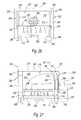
- FIG. 1is a perspective view of the oven of the present invention
- FIG. 2is a rear view of the oven of FIG. 1 ;
- FIG. 3is a perspective view of an air filter frame for the oven of FIG. 1 ;
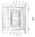
- FIG. 4is a cross-sectional view along line 4 of FIG. 1 that depicts the oven in a convection mode
- FIG. 5is a cross-sectional view along line 4 of FIG. 1 that depicts the oven in an impingement mode
- FIG. 6is a view along line 4 of FIG. 1 that depicts the oven in a microwave mode
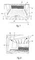
- FIG. 7is a perspective view of a portion of the oven of FIG. 1 with the oven door open that depicts the lower impingement plate installed;
- FIG. 8is a perspective view of a portion of the oven of FIG. 1 with the oven door open that depicts the upper impingement plate installed;
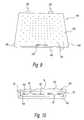
- FIG. 9is a top view of the lower impingement plate of the oven of FIG. 1 ;
- FIG. 10is a cross-sectional view of FIG. 7 along line 10 ;
- FIG. 11is a perspective view of the upper impingement plate of the oven of FIG. 1 ;
- FIG. 12is a front view of the upper impingement plate of the oven of FIG. 1 ;
- FIG. 13is a detail view of an interlock assembly mounted in place on a hinge of the door of the oven of FIG. 1 ;
- FIG. 14is a perspective view of the interlock assembly of FIG. 13 ;
- FIG. 15is a top view of the interlock assembly of FIG. 14 ;
- FIG. 16is a front view of the interlock assembly of FIG. 14 ;
- FIG. 17is a side view of the interlock assembly of FIG. 13
- FIG. 18is a perspective view of another embodiment of the oven of the present invention.
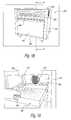
- FIG. 19depicts a portion of the oven of FIG. 18 with the door open;
- FIG. 20is a view along line 20 of FIG. 21 ;
- FIG. 21is a cross-sectional view along line 21 of FIG. 18 ;
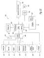
- FIG. 22is a block diagram of the controller of the oven of FIG. 1 ;
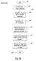
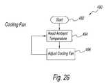
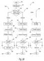
- FIGS. 23-28are flow diagrams of program mode features of the controller of FIG. 22 .
- a combination oven 30 of the present inventioncomprises a pair of outer side walls 32 and 34 , an outer back wall 36 , an outer top wall 38 , an outer bottom wall 40 and a front wall 41 , all of which comprise an outer enclosure.
- Front wall 41comprises a door 42 , a control panel 44 above door 42 and a grease drawer 46 below door 42 .
- a handle 48is disposed on door 42 for opening the door in a pull down manner.
- Outer bottom wall 40is offset from outer side walls 32 and 34 , outer back wall 36 and front wall 41 .
- the offsetis preferably a bevel 50 , but could be have other shapes.
- An air intake port 52 and an air intake port 54are located in opposed sides of bevel 50 adjacent outer side walls 32 and 34 , respectively.
- Air filters 56 and 58are disposed at air intake ports 52 and 54 , respectively. Ambient air is taken in via air intake ports 52 and 54 to cool various control parts, a fan motor (not shown), outer side walls 32 and 34 , outer bottom wall 40 and outer top wall 38 and outer back wall 36 .
- the cooling airexits oven 30 via a plurality of louvers 60 disposed in outer back wall 36 .
- Combination oven 30is configurable for operation in a convection mode, an impingement mode, a microwave mode, a combination convection and microwave mode, a combination impingement and microwave mode and a combination microwave, impingement and convection mode.
- combination oven 30is shown configured for a convection mode.
- Combination oven 30comprises an oven chamber 70 and a fan box 72 supported by a support structure 68 , which is mechanically connected to outer bottom wall 40 and outer side walls 32 and 34 .
- Oven chamber 70 and fan box 72share an inner top wall 76 , an inner bottom wall 78 and inner side walls 80 and 82 , inner side wall 82 being shown only in FIGS. 6 and 7 .
- Oven chamber 70 and fan box 72also share a vertically disposed baffle plate 74 .
- oven chamber 70comprises door 42 , baffle plate 74 , inner top wall 76 , inner bottom wall 78 and inner side walls 80 and 82 .
- Fan box 72comprises baffle plate 74 , inner top wall 76 , inner bottom wall 78 , inner side walls 80 and 82 and an inner back wall 84 .
- a fan 85is disposed in fan box 72 and a heater 87 is disposed downstream of fan 85 .
- Fan 85may be any fan suitable for circulating heated air in an oven.
- fan 85is a three phase cage induction motor suitable for inverter drive, preferably L7FWDS-638 manufactured by Hanning.
- Heater 87may be any heater (gas or electric) suitable for heating circulating air in a convection and/or impingement air oven.
- heater 87is an electrical heater having one or more heating elements disposed above and below the blades of fan 85 .
- baffle plate 74comprises a plurality of openings to provide a path for air to circulate between oven chamber 70 and fan box 72 .
- a first opening 86(shown only in FIG. 7 ) is located above the bottom of baffle plate 74 .
- a grease filter 88is mounted to baffle plate 74 to cover opening 86 , which is preferably at least partially in registration with fan 85 .
- a second opening 90is located at or near the top of baffle plate 74 .
- One or more third openings 92are located near the bottom of baffle plate 74 .
- Grease filter 88is advantageously located upstream airflow to the suction side of fan 85 to filter grease and/or other particles from the circulating air stream before reaching the blades of fan 85 .
- Grease filter 88is also located in a readily accessible position for removal and cleaning.
- the oven chamber inner walls 80 and 82are shaped so that grease and other liquid flows downwardly toward grease drawer or pan 46 . Since grease drawer 46 is readily removable, it is easy to clean.
- a catalyst structure 96is disposed in fan box 72 between fan 85 and baffle plate 74 .
- Catalyst structure 96comprises a catalyst 98 , a catalyst 100 and a catalyst 102 .
- Catalyst 98is disposed adjacent inner top wall 76 in at least partial registration with opening 90 of baffle plate 74 .
- Catalyst 100is disposed at least in partial registration with grease filter 88 and fan 85 .
- Catalyst 102is disposed in registration with openings 92 .
- a fan cover 104has an opening 106 and is disposed between fan 85 and catalyst 100 so that opening 106 is in registration with fan 85 and catalyst 100 .
- Catalyst 100may suitably be a sheet material with a plurality of apertures.
- catalyst 100may be 12 ⁇ 12 0.041 inch diameter open wire mesh available from Englehard.
- Catalysts 98 and 102may suitably be 0.0006 inches metal foil hemingbone pattern substrate with platinum catalyst 105 cell per square inch available from Englehard.
- an oven rack 108is disposed in oven chamber 70 on supports 110 mounted to inner side walls 80 and 82 so that oven rack 108 is near the bottom of grease filter 88 and above openings 92 .
- Oven rack 108may be a standard food rack, i.e., available off-shelf.
- a microwave opening 112is disposed in inner side wall 80 and a microwave opening 116 is disposed in inner side wall 82 .
- a cover 114 and a cover 118are disposed to cover openings 112 and 116 , respectively.
- Covers 114 and 118are microwave transparent.
- the coversmay be a suitable ceramic or other microwave transparent material.
- Outer walls 32 , 34 , 36 , 38 and 40which comprise an outer enclosure, inner walls 76 , 78 , 80 , 82 and 84 , which comprise an inner enclosure, and baffle plate 74 are preferably a metal, such as stainless steel.
- Inner walls 76 , 78 , 80 , 82 and 84are separated from outer walls 32 , 34 , 36 , 38 and 40 by a passageway 120 for cooling air in combination oven 30 .
- a cooling fan 122is disposed in passageway 120 below oven chamber 70 and between outer bottom wall 40 and inner bottom wall 78 .
- a fan motor compartment 124 and one or more microwave generators 126are disposed in passageway 120 between outer back wall 36 and inner back wall 84 .
- a fan motor(not shown) is disposed in fan motor compartment 124 and is coupled to rotate fan 85 .
- a suitable thermal insulation(not shown) is disposed in passageway 120 about oven chamber 70 and fan box 72 .
- air filter holder 130that permits easy installation and removal of air filter 56 .
- air filter holder 130comprises flanges 132 and 134 that are shaped for installation and removal of air filter 56 by a sliding motion.
- Air filter holder 130also comprises an opening 136 that is in registration with air intake port 52 .
- Air filter holder 130is mounted to bevel 50 by any suitable fastener, such as screws.
- air filter holder 130can be formed in bevel 50 by stamping or other metal working process. It will be apparent to those skilled in the art that a similar air filter holder 130 is provided for air filter 58 .
- Air filters 56 and 58each comprise an array of perforations.
- the perforationsmay simply be the mesh of a screen, such as screen 138 , a portion of which is shown for air filter 56 .
- cooling fan 122is operable to circulate cooling air in passageway 120 .
- the cooling airis drawn into passageway 120 from ambient via air intake ports 52 and 54 and flows through passageway 120 and exits via louvers 60 in outer back wall 36 to cool various control parts, the fan motor (not shown), microwave generators 126 , outer side walls 32 and 34 , outer bottom wall 40 , outer top wall 38 and outer back wall 36 .
- air intake ports 52 and 54By locating air intake ports 52 and 54 in bevel 50 , combination oven 30 can be located side by side with other structures (e.g., a wall), i.e., outer side walls 32 and 34 being flush against the other structures. This conserves space and allows combination oven 30 to have a smaller footprint than prior ovens.
- fan 85circulates air drawn from oven chamber 70 into fan box 72 via grease filter 88 and catalyst 100 .
- the airis heated by heater 87 and circulated to oven chamber via catalyst 98 and catalyst 102 .
- Grease filter 88 and catalyst 100function to remove contaminates (e.g., grease particles and other contaminates) from the air prior to contact with fan 85 .
- Catalysts 98 and 102function to further purify the air prior to circulation into oven chamber 70 .
- combination oven 30is also configurable in an impingement mode by installing removable lower and/or upper impingement plates 150 and 152 , respectively.
- lower impingement plate 150comprises a frame 154 that has a top side 156 , a front side 158 , a left side 160 and a right side 162 .
- Top side 156comprises an array of jet holes 164 shaped to provide jets or columns of impingement air.
- Frame 154is dimensioned for installation by sliding motion along inner bottom wall 78 .
- a handle 159is disposed on top side 156 . Also, as shown in FIG.
- one or more guides or locators 166are provided to assure that frame 154 is installed flush with baffle plate 74 to minimize air leakage.
- Guides 166mate with similar guides in baffle plate 74 .
- Guides 166 and their mating guidesmay be any suitable guides that mate, e.g., tab and slot, flange and flange, and other mating guides.
- impingement plate 150When installed, impingement plate 150 forms with inner bottom wall 78 an impingement plenum that is in fluid communication with fan box 72 via openings 92 in baffle plate 74 .
- airflow from fan box 72 through holes 92pressurizes lower impingement plate 150 to provide jets or columns impingement of impingement air toward oven rack 108 , as indicated by the vertical upwardly extending arrows in FIG. 5 .
- perforations or jet holes 164 in a central area of top side 156 of impingement plate 150are shown as closely spaced. This directs most of the impingement air to a central area of oven rack 108 so as to impinge directly on the food product. There are fewer jet holes 164 (less closely spaced jet holes) near the edges. This assures that most of the impingement air will be concentrated toward the center for food products like pizza.
- upper impingement plate 152comprises a comprises a frame 170 that has a bottom side 172 , a front side 174 , a left side 176 and a right side 178 .
- Bottom side 172comprises an array of jet holes 180 shaped to provide jets or columns of impingement air as indicated by the vertical downwardly extending arrows in FIG. 5 .
- Front side 174 , left side 176 and right side 178extend above bottom side 172 .
- Front side 174 , left side 176 and right side 178are fastened to bottom plate 172 by any suitable fastener, such as screws, weldment or other suitable fastener.
- frame 170can be formed as an integral one-piece construction. Frame 170 is dimensioned for installation in oven chamber 70 against inner top wall 76 and baffle plate 74 in registration with opening 90 and catalyst 98 . Upper impingement plate 152 is installed with fasteners, such as screws 182 to inner top wall 76 .
- front side 174is angled for an air diversion function to provide a more uniform air pressure throughout the delivery plenum to assure that the air jets 180 remote from the airflow entry at opening 90 have the same velocity as those that are nearer to opening 90 .
- the lower impingement platecould also be provided with an air diverter.
- fan 85circulates air drawn from oven chamber 70 into fan box 72 via grease filter 88 and catalyst 100 .
- the airis heated by heater 87 and circulated to oven chamber via catalysts 98 and 102 and lower and upper impingement plates 150 and 152 , respectively.
- grease filter 88 and catalyst 100function to remove contaminates (e.g., grease particles and other contaminates) from the air prior to contact with fan 85 .
- Catalysts 98 and 102function to further purify the air prior to circulation into lower and upper impingement plates 150 and 152 for delivery as impingement air to oven chamber 70 .
- Combination oven 30can also be operated in microwave and both impingement and convection mode by removal of either upper impingement plate 152 or lower impingement plate 150 , but not both. If both impingement plates 150 and 152 are removed, oven 3 will function in a convection mode or a combination convection and microwave mode.
- combination oven 30is configured in a combination microwave and impingement mode.
- Upper and lower impingement plates 150 and 152are installed.
- a microwave generatorcomprising one or more magnetrons 126 ( FIG. 4 ) and a pair of wave-guides (not shown) provides microwave energy through entry openings or ports 112 and 116 disposed in inner side walls 80 and 82 , respectively.
- the wave-guidesextend from microwave generators 126 in passageway 120 ( FIGS. 4 and 5 ) to openings 112 and 116 .
- This combination of microwave energy feed from opposed inner side walls 80 and 82 and impingement air from above and/or belowis a significant feature of the present invention.
- Microwave energy from both inner side walls 80 and 82provide direct microwave energy to the sides, top and bottom of a food product disposed on food rack 108 . Impingement air from above and below impinges and browns the top and bottom of the food product. If browning is not desired on the bottom, for example, lower impingement plate 150 is removed. The oven then is configured for microwave, impingement (from the top) and convection. An alternative arrangement would be the removal of upper impingement plate 152 while retaining lower impingement plate 150 for products that require bottom browning and a gentle convection heat, i.e., delicate pastries. Due to microwave energy being launched from one or more side walls, metal pans can be used in oven 30 .
- low profile metal panssuch as those used for baking pastries and other foods, can be used to hold food products during cooking without reflected microwave energy seriously impairing the useful life of magnetrons 126 .
- Microwave energyis signified in FIG. 6 with arrows directed into oven chamber 70 from openings 112 and 116 .
- Impingement cookingis signified by the arrows in FIG. 4 .
- Cooling fan 122is preferably a variable speed fan so as to minimize noise and energy consumption while still maintaining low temperature of critical components. This is to be contrasted with known ovens that have a fixed speed cooling fan that is always on or a delayed turn-on and a delayed turn-off.
- Combination oven 30comprises a temperature probe (not shown) that is located (e.g., in the vicinity of magnetrons 126 ) to provide a signal proportional to temperature of critical or temperature sensitive components.
- An oven controlleruses the signal to regulate the cooling fan speed accordingly.
- a magnetronwill only generate heat while it is operating, thereby requiring a relatively large amount of cooling air to keep the temperature sensitive components from overheating.
- combination oven 30 of the present inventionalso comprises an interlock switch assembly 200 that is disposed on a hinge 190 that is fastened to door 42 by fasteners 191 and 193 and to a frame 192 by a fastener 194 .
- Frame 192is supported by bottom wall 40 .
- Hinge 190comprises a pivot 195 , which is coupled by a spring 196 to a cam 197 .
- interlock assembly 200includes an angled bracket 202 that comprises a first portion 204 and end portions 206 and 208 that extend at an angle, preferably a right angle, thereto, at spaced apart locations. Preferably, the spaced apart locations are at opposed ends of portion 204 .
- a plunger 210has a portion 230 that extends through openings 212 and 214 of portions 206 and 208 of bracket 202 , respectively.
- a fastener 216extends through an opening 218 in portion 230 of plunger 210 just outside portion 208 of bracket 202 .
- Plunger 210has a right angle portion 220 just outside of portion 206 of bracket 202 by a distance depicted as d in FIG. 18 .
- plunger 210The motion of plunger 210 is limited to the distance d by the locations of fastener 216 and right angle portion 220 .
- Plunger portion 230comprises a neck section 232 that carries a spring 228 between a stop 234 thereof and portion 208 of bracket 202 .
- Plunger portion 230also comprises a cam surface 236 and a cam surface 238 .
- a micro-switch 240has a contact element 242 in contact with cam surface 236 .
- a micro-switch 244has a contact element 246 in contact with cam surface 238 .
- Cam surfaces 236 and 238are shaped such that micro-switches 240 and 244 are activated in sequence as plunger moves to the right or the left as viewed in FIG. 15 .
- the ramps to the left side of cam surfaces 236 and 238are offset from one another by an amount that yields the time differential in the sequence of activation, i.e., the turning on and off of micro-switches 240 and 244 .
- the motion of plunger 210is controlled by the motion of cam 197 as oven door 42 rotates about hinge 190 of combination oven 30 .
- plunger 210is as shown in FIGS. 14-17 when door 42 is open.
- Spring 228is in its least compressed condition.
- cam 197engages and moves plunger 210 up in FIG. 13 (to the right in FIGS. 14-17 ).
- contact elements 242 and 246encounter the left hand ramps of cam surfaces 236 and 238 in sequence to activate their respective micro-switches 240 and 244 .
- the left hand ramp of cam surface 236is encountered first (its ramp is offset slightly to the right from that of cam surface 238 ).
- micro-switch 240is activated first and then micro-switch 244 is activated.
- spring 228compresses.
- micro-switch 244When door 42 is opened, spring 228 decompresses and returns plunger 210 to the position shown in FIGS. 14-17 . As plunger 210 moves to the left, micro-switch 244 is activated first and then micro-switch 240 is activated. Micro-switches 240 and 244 are connectable in circuit with other components to shut off microwave power, oven heating and reduces fan speed to 10% airflow as door 42 opens. The assembly is robust enough to assure the correct sequencing of micro-switches 240 and 244 even upon the occurrence of jarring events, such as slamming of the oven door.
- a substantially identical interlock assemblyis incorporated in the hinge assembly for the other side of door 42 .
- the switch assembly application(two interlock assemblies, one on each door hinge) serve to comply with the UL923 safety standard requiring a crowbar circuit to render the unit safe if a switch were to fail.
- a control system(not shown) generates continuous reduced microwave power without generating large current flicker in the mains power supply. This is only applicable in a microwave oven containing N magnetrons (N>1) where the filament current is supplied separate from the high voltage transformers. There are two advantages with this arrangement. First, the food quality of items rises during cooking.
- the controllerincludes a special control mode that aids in the recipe cooking parameters.
- the controllerasks for certain parameters and then suggests suitable cooking parameters.
- the controllerposes questions to evaluate the desired quality and modifies the cooking parameters automatically with a possible manual override. This will continue until a satisfactory result has been achieved and the program can be stored automatically in the controller.
- the controllercomprises a CPU (central processing unit), a switching unit with variable speed drive for fans, a key reader, an input switch matrix, an alarm/beeper, a non-volatile memory, a cavity temperature sensor, magnetron temperature sensors and a display module.
- the controllerincludes the features of uploading and downloading cooking programs (500 ⁇ 8 stages).
- the controlleralso includes a cool down mode that allows a 24/7 store operator to rapidly cool down the oven using ice. This process is fully automated and only advises the operator when the oven is cool and safe to clean.
- the controlleralso has a configuration or profile mode that allows individual customers to set up their preferred mode of operation, i.e., manual or programmed or preprogrammed only.
- Other variables that can be either set by the menu key or by the operatorare beeper loudness, language, oven operating temperature band (to insure consistent cooking results), Degrees F or C and whether during operation the actual oven temperature or the set temperature is displayed.
- the controllerutilizes an averaging mode where a temperature measurement is taken every 30 seconds and the actual oven temperature is calculated from the average of the last ten readings. Also to help in this area the controller switches the heater on for a fixed period whenever the door is opened.
- oven 250comprises a pair of outer side walls 252 and 254 , an outer back wall 256 , an outer top wall 258 , an outer bottom wall 260 and a front wall 261 , all of which comprise an outer enclosure.
- Front wall 261comprises a door 262 and a control panel 264 above door 262 .
- a handle 268is disposed on door 262 for opening the door in a pull down manner.
- Combination oven 250is configurable for operation in a convection mode and a combination impingement and convection mode.
- oven 250comprises an oven chamber 270 and a fan box 272 supported by a support structure 266 .
- Oven chamber 270 and fan box 272share an inner top wall 276 , an inner bottom wall 278 and inner side walls 280 and 282 .
- Oven chamber 270 and fan box 272also share a vertically disposed baffle plate 274 .
- oven chamber 270comprises door 262 , baffle plate 274 , inner top wall 276 , inner bottom wall 278 and inner side walls 280 and 282 .
- Fan box 272comprises baffle plate 274 , inner top wall 276 , inner bottom wall 278 , inner side walls 280 and 282 and an inner back wall 284 .
- Support structure 266is mechanically connected to outer bottom wall 260 , outer side walls 252 and 254 and inner bottom wall 278 .
- a fan 286is disposed in fan box 272 and a heater 288 is disposed downstream of fan 286 .
- Fan 286may be any fan suitable for circulating heated air in an oven.
- Heater 288may be any heater (gas or electric) suitable for heating circulating air in a convection and/or impingement air oven.
- heater 288is an electrical heater having one or more heating elements disposed above and below the blades of fan 286 .
- baffle plate 274comprises a plurality of openings to provide a path for air to circulate between oven chamber 270 and fan box 272 .
- baffle plate 274is mounted offset by an opening or gap 290 from inner side walls 280 and 282 and inner top wall 276 .
- Baffle plate 274is also offset from inner bottom wall 278 by a gap 291 .
- Baffle plate 274also includes an intake port 292 located centrally and in registration with at least a portion of the blades of fan 286 .
- Intake port 292comprises a plurality of apertures 294 .
- Fan 286circulates air heated by heater 288 through gap 290 into oven chamber 270 and takes in the circulating air via intake port 292 as shown by arrow 296 in FIG. 21 .
- a grease filter and/or a catalystmay be located upstream to the suction side of fan 286 (e.g., at intake port 292 ) to filter grease particles and other contaminates from the circulating air stream.
- an oven rack 298is disposed in oven chamber 270 on supports 300 mounted to inner side walls 280 and 282 so that oven rack 108 is near the bottom of intake port 292 .
- Oven rack 298may be a standard food rack, i.e., available off-shelf.
- Outer walls 32 , 34 , 36 , 38 and 40which comprise an outer enclosure, inner walls 76 , 78 , 80 , 82 and 84 , which comprise an inner enclosure, and baffle plate 74 are preferably a metal, such as stainless steel.
- a fan motor 302is disposed in the space between inner back wall and outer back wall is coupled to rotate fan 286 .
- a suitable thermal insulation(not shown) is disposed in passageway 120 about oven chamber 70 and fan box 72 .
- Inner walls 276 , 278 , 280 , 282 and 284are separated from outer walls 252 , 254 , 256 , 258 and 260 by a passageway 304 for cooling air in oven 250 .
- a cooling fan 306is disposed in passageway 304 below oven chamber 270 and between outer bottom wall 260 and inner bottom wall 278 .
- a fan motor 302 and other componentsare disposed in passageway 304 .
- a fan motor(not shown) is disposed in fan motor compartment 124 and is coupled to rotate fan 286 .
- a suitable thermal insulation(not shown) is disposed in passageway 304 about oven chamber 270 and fan box 272 .
- Cooling fan 306is operable to circulate cooling air in passageway 304 .
- the cooling airis drawn into passageway 304 from ambient via suitably located air intake ports (not shown) and flows through passageway 304 and exits via suitably located exit ports (not shown) to cool various control parts, fan motor 302 and other control parts.
- the intake portscould be located along outer side walls near outer bottom wall and the output ports in outer back wall 256 as in oven 30 of FIG. 1 .
- oven 250For convection operation of oven 250 , fan 286 circulates air drawn from oven chamber 270 into fan box 272 via intake port 292 . The air is heated by heater 288 and circulated to oven chamber 270 via gaps 290 and 291
- oven 250is also configurable in an impingement mode by installing a removable lower impingement plate, which is substantially identical to and bears the same reference numeral as lower impingement plate 150 of oven 30 .
- Lower impingement plate 150is dimensioned for installation by sliding motion along inner bottom wall 278 .
- Handle 158facilitates installation and removal.
- a pair of stops 310FIGS.
- flange 312is located along the bottom edge of baffle plate 274 to facilitate a flush installation of impingement plate 150 and baffle plate 274 to minimize air leakage.
- stops 310can be replaced with any suitable guide or stop.
- flange 312can be suitably shaped to engage the top of lower impingement plate 150 at one or more locations to provide a flush fit.
- impingement plate 150When installed, impingement plate 150 forms with inner bottom wall 278 an impingement plenum that is in fluid communication with fan box 272 via gap 291 below baffle plate 274 .
- airflow from fan box 272 through gap 291pressurizes lower impingement plate 150 to provide jets or columns impingement of impingement air toward the underside of a food product located on oven rack 298 , as indicated by the vertical upwardly extending arrows in FIGS. 20 and 21 .
- the back side of lower impingement plate 150has an opening (not shown) to accept air from the gap between the fan cover and the bottom wall of the oven.
- the openingcan encompass all (back side totally open) or a portion of the back side of impingement plate 150 .
- the boxis shaped so as to slide beneath the bottom edge of baffle plate 274 during installation and removal.
- Flange 312assists in the sliding motion.
- Flange 312 and lower impingement plate 150are dimensioned for the sliding motion and for a relative tight fit to effectively deliver the airflow to the impingement plate with an adequate air pressure to produce the impingement columns with minimal air leakage at the back of lower impingement plate 150 .
- a pair of vertical baffle structures 314 and 316is mounted on opposite sides of fan 286 in fan box 272 .
- baffle plate 274is mounted to vertical baffle structures 314 and 316 .
- Vertical baffle structures 314 and 316also serve as baffles or guides to direct more of the airflow around the top and bottom edges and a lesser airflow about the sides of baffle plate 174 .
- the vertical structuresare spaced a slight distance 318 from inner back wall 284 to provide a pair of vertical slots 318 , which are narrow compared to the distance (gap 290 ) between the top of baffle plate 274 and inner top wall 276 and to the distance (gap 291 ) between the bottom of baffle plate 274 and inner bottom wall 278 .
- Vertical baffle structures 314 and 316do not extend above the top of baffle plate 274 so as to permit the top airflow to extend from inner side wall 280 to inner side wall 282 of oven 250 .
- vertical baffle structures 314 and 316extend below baffle plate 274 to inner bottom wall 278 , i.e., the bottom of impingement plate 150 .
- the less closely spaced jet holes near the edges of impingement plate 150provides lesser impingement air to the side s of a food product on the oven rack.
- convection airalso flows around the edges of baffle plate 274 and off inner side walls 280 and 282 of oven chamber 270 . This helps with browning of the bottom of the food product portions that are near inner side walls 280 and 282 .
- Oven 250can alternatively be provided with a removable upper impingement plate (not shown) similar to upper impingement plate 152 of oven 30 to provide impingement air from above either in place of or in addition to lower impingement plate 150 .
- a microwave facilitymay be disposed adjacent one of the oven walls, e.g., the top wall, and can also be used in a microwave mode or in combination with the heated air stream in either an impingement mode or a non-impingement mode.
- controller 400is shown for oven 30 .
- Controller 400is similar to the controller shown in U.S. Pat. Nos. 6,660,982 and 6,903,318, which are hereby incorporated by reference.
- controller 400includes a central processing unit (CPU) 408 that is interconnected with a key reader 402 , a manual control panel 404 , a display unit 407 , an audio alarm/beeper 410 , a control interface 409 , a memory 411 and oven 30 .
- CPU 408comprises a processor 405 and a memory 406 .
- Oven 30comprises an oven temperature sensor 401 that is located in oven chamber 70 .
- Oven temperature sensor 401provides a signal that is proportional to the temperature of oven chamber 70 . This signal is coupled to CPU 408 .
- Key reader 402is operable to read information carried on a key. This information may include program data corresponding to different cooking sequences at a data site, and is then sent to the cooking site for use with oven 30 and optionally with other ovens.
- Control interface 409is interconnected with a number of devices of oven 30 . To this end, control interface 409 is interconnected with cooling fan 122 , oven fan 85 , heaters 87 , magnetrons 126 , a magnetron temperature sensor 415 , an ambient temperature sensor 403 and a memory 411 .
- a plurality of control programsis stored in memory 411 and/or key 400 .
- a cool down program or mode 420is used by CPU to control a cool down of oven 30 .
- Cool down programbegins at start box 422 and proceeds to step 424 , which tests or samples a current temperature of oven chamber 70 provided by oven temperature sensor 401 .
- Step 426determines if the cavity (oven chamber 70 ) is too hot. For example, step 426 determines if the current oven temperature greater than a predetermined temperature limit. If not, the user is informed on display unit 407 that the oven chamber is cool. If step 426 determines that the current oven temperature is too hot, the user is instructed to place a load of ice in oven chamber 70 . Step 436 then automatically adjusts the speed of fan 85 and/or cooling fan 122 .
- Step 428then tests the temperature of oven chamber 70 based on the temperature signal provided by oven temperature sensor 401 .
- Step 430determines if the cavity is hot. For example, step 430 determines if the oven chamber temperature above a safe limit at or below which it is safe for an operator to clean or service oven 30 . If yes, cool down mode reiterates in the loop of steps 428 and 430 until step 430 determines that the oven chamber temperature has dropped to or below the safe limit. When this happens, step 432 informs the user that the oven is cool with a message on display unit 407 . Cool down program 400 ends at step 458 .
- a duty cycle control mode 440is used by CPU to control the duty cycle of the magnetrons.
- Duty cycle program 440begins at start box 442 and proceeds to step 444 , which converts total microwave cook time to seconds.
- Step 446then divides the total time by 40 and calculates a remainder. As an example, assume a total microwave cook time of 50 seconds and a duty cycle of 25%.
- Step 446calculates one interval of 40 seconds and a remainder of 10 seconds.
- Step 448converts the remainder of ten seconds into tenths of a second by multiplying by 10 for a total of 100 tenths of a second.
- Step 450then calculates the on time of magnetrons 126 for the 25% duty cycle of the 40 second interval and the ten second remainder.
- Step 452executes the cooking stages at 40 second intervals, which for the assumed example is one 40 second interval.
- Step 456then executes a last stage using the remainder on time for magnetrons 126 .
- Duty cycle control mode 440ends at step 458 .
- a magnetron error program 470is used by CPU 408 to handle magnetron errors.
- Magnetron error program 470begins at start box 472 and proceeds to step 474 , which tests the temperature of magnetrons 126 .
- Step 474samples the temperature signal provided by magnetron sensor 415 to provide a current magnetron temperature.
- Step 476determines if the magnetron current temperature is okay. For example, the current temperature is okay if it is in a range having a predetermined upper limit of too hot (magnetron overheated) and a lower limit of too cold (magnetron shutdown or other failure).
- Step 480then resets a counter.
- Step 482determines if the counter value is an error.
- step 480reset the counter there is no error and magnetron error program 470 would then end at step 486 . If step 476 determines that the current magnetron temperature is outside the range, step 478 decrements the counter. Step 482 would the determine that the counter value is an error and step 484 displays a message on display unit 407 informing the user to disable the oven.
- a cooling fan control program 490begins at start 492 and proceeds to step 494 , which reads the current ambient temperature from ambient temperature sensor 415 . Based on the current ambient temperature, controller 400 adjusts the speed of cooling fan 122 . For example, the cooling fan speed is adjusted higher for warmer ambient temperatures and lower for cooler ambient temperatures.
- a profile program 500begins at start 502 and proceeds to step 504 , which reads a default oven profile.
- Step 506displays the default oven profile on display unit 407 .
- the oven profileincludes a plurality of parameters affecting the user interface, such as language to be used, temperature units ° F. or ° C., manual or program mode, beeper volume or sound and others.
- the user at step 510can input changes to the profile parameters.
- Step 512validates the entered changes.
- Step 508determines if the user has entered any change. If yes, step 514 modifies the profile and step 506 displays the change. The user chan then edit the change or make other changes.
- profile program 500iterates in the loop of steps 506 , 508 and 514 until step 508 determines that the user has not entered a change.
- Step 516determines if the profile entry is the last profile parameter. If not, profile program 500 returns to iterate in the loop of steps 506 , 508 , 514 and 516 until step 516 determines that the current profile entry is the last profile entry.
- Step 506displays the next profile parameter and steps 508 and 514 .
- Profile programthen ends at step 518 .
- a down and upload program 530controls data and program downloads and uploads between controller 400 and menu key 400 .
- Download and upload program 530begins at start 532 and proceeds to step 534 , which detects a menu key 400 at key reader 402 .
- Step 536identifies whether menu key 400 is inserted for a firmware upload, a program download or a program upload.
- step 536identifies a firmware upgrade
- step 536identifies a firmware upgrade
- step 542transfers the firmware to CPU memory 406 .
- Step 543performs a checksum of the firmware data.
- Step 546determines if the firmware update is okay. If yes, step 547 displays a message on display unit 407 that the upgrade is okay. If no, step 547 displays a message on display unit 407 that the upgrade is not okay.
- Firmware upgrade routine 540then ends at step 548 .
- step 536identifies a program download
- Program download routine 550begins at step 551 , which identifies the programs to be downloaded.
- Step 552transfers the programs to memory 411 .
- Step 553performs a checksum of the program data.
- Step 554determines if the program download is okay. If yes, step 556 displays a message on display unit 407 that the program download is okay. If no, step 556 displays a message on display unit 407 that the program download is not okay.
- Program download routine 550then ends at step 557 .
- step 536identifies a program upload
- Program upload routine 560begins at step 561 , which identifies the programs to be downloaded.
- Step 562transfers the programs to memory 411 .
- Step 563performs a checksum of the program data.
- Step 564determines if the program upload is okay. If yes, step 565 displays a message on display unit 407 that the program upload is okay. If no, step 565 displays a message on display unit 407 that the program upload is not okay.
- Program upload routine 550then ends at step 566 .
Landscapes
- Physics & Mathematics (AREA)
- Electromagnetism (AREA)
- Thermal Sciences (AREA)
- Life Sciences & Earth Sciences (AREA)
- Engineering & Computer Science (AREA)
- Food Science & Technology (AREA)
- Electric Ovens (AREA)
- Constitution Of High-Frequency Heating (AREA)
- Saccharide Compounds (AREA)
- Electric Stoves And Ranges (AREA)
- Baking, Grill, Roasting (AREA)
Abstract
Description
- sampling an output of a temperature sensor located in the vicinity of the microwave generator for a current temperature of the microwave generator;
- determining whether the current temperature is acceptable; and
- if the current temperature is unacceptable, causing the oven to be disabled.
- calculating N and the remainder; and
- calculating the on and off time of the microwave generator for the N cooking stages and the remainder cooking stage, based on the predetermined duty cycle.
- calculating N and the remainder; and
- calculating the on and off time of the microwave generator for the N cooking stages and the remainder cooking stage, based on the predetermined duty cycle.
Claims (16)
Priority Applications (6)
| Application Number | Priority Date | Filing Date | Title |
|---|---|---|---|
| US11/302,638US8071922B2 (en) | 2004-12-14 | 2005-12-14 | Impingement/convection/microwave oven and method |
| US11/891,104US8093538B2 (en) | 2004-12-14 | 2007-08-09 | Impingement/convection/microwave oven and method |
| US11/891,212US7834299B2 (en) | 2004-12-14 | 2007-08-09 | Impingement/convection/microwave oven and method |
| US11/891,229US7838807B2 (en) | 2004-12-14 | 2007-08-09 | Impingement/convection/microwave oven and method |
| US13/282,366US20120067226A1 (en) | 2004-12-14 | 2011-10-26 | Impingement/convection/microwave oven and method |
| US13/329,003US20120152936A1 (en) | 2004-12-14 | 2011-12-16 | Impingement/convection/microwave oven and method |
Applications Claiming Priority (4)
| Application Number | Priority Date | Filing Date | Title |
|---|---|---|---|
| US63585704P | 2004-12-14 | 2004-12-14 | |
| US68259405P | 2005-05-19 | 2005-05-19 | |
| US73524105P | 2005-11-09 | 2005-11-09 | |
| US11/302,638US8071922B2 (en) | 2004-12-14 | 2005-12-14 | Impingement/convection/microwave oven and method |
Related Child Applications (4)
| Application Number | Title | Priority Date | Filing Date |
|---|---|---|---|
| US11/891,212DivisionUS7834299B2 (en) | 2004-12-14 | 2007-08-09 | Impingement/convection/microwave oven and method |
| US11/891,229DivisionUS7838807B2 (en) | 2004-12-14 | 2007-08-09 | Impingement/convection/microwave oven and method |
| US11/891,104DivisionUS8093538B2 (en) | 2004-12-14 | 2007-08-09 | Impingement/convection/microwave oven and method |
| US13/282,366ContinuationUS20120067226A1 (en) | 2004-12-14 | 2011-10-26 | Impingement/convection/microwave oven and method |
Publications (2)
| Publication Number | Publication Date |
|---|---|
| US20060157479A1 US20060157479A1 (en) | 2006-07-20 |
| US8071922B2true US8071922B2 (en) | 2011-12-06 |
Family
ID=36588469
Family Applications (6)
| Application Number | Title | Priority Date | Filing Date |
|---|---|---|---|
| US11/302,638Expired - Fee RelatedUS8071922B2 (en) | 2004-12-14 | 2005-12-14 | Impingement/convection/microwave oven and method |
| US11/891,104Expired - Fee RelatedUS8093538B2 (en) | 2004-12-14 | 2007-08-09 | Impingement/convection/microwave oven and method |
| US11/891,212Expired - Fee RelatedUS7834299B2 (en) | 2004-12-14 | 2007-08-09 | Impingement/convection/microwave oven and method |
| US11/891,229Expired - Fee RelatedUS7838807B2 (en) | 2004-12-14 | 2007-08-09 | Impingement/convection/microwave oven and method |
| US13/282,366AbandonedUS20120067226A1 (en) | 2004-12-14 | 2011-10-26 | Impingement/convection/microwave oven and method |
| US13/329,003AbandonedUS20120152936A1 (en) | 2004-12-14 | 2011-12-16 | Impingement/convection/microwave oven and method |
Family Applications After (5)
| Application Number | Title | Priority Date | Filing Date |
|---|---|---|---|
| US11/891,104Expired - Fee RelatedUS8093538B2 (en) | 2004-12-14 | 2007-08-09 | Impingement/convection/microwave oven and method |
| US11/891,212Expired - Fee RelatedUS7834299B2 (en) | 2004-12-14 | 2007-08-09 | Impingement/convection/microwave oven and method |
| US11/891,229Expired - Fee RelatedUS7838807B2 (en) | 2004-12-14 | 2007-08-09 | Impingement/convection/microwave oven and method |
| US13/282,366AbandonedUS20120067226A1 (en) | 2004-12-14 | 2011-10-26 | Impingement/convection/microwave oven and method |
| US13/329,003AbandonedUS20120152936A1 (en) | 2004-12-14 | 2011-12-16 | Impingement/convection/microwave oven and method |
Country Status (15)
| Country | Link |
|---|---|
| US (6) | US8071922B2 (en) |
| EP (3) | EP2408264B1 (en) |
| JP (1) | JP2008523352A (en) |
| KR (1) | KR20070116784A (en) |
| CN (5) | CN101496447B (en) |
| AT (1) | ATE536078T1 (en) |
| AU (1) | AU2005316586B2 (en) |
| CA (3) | CA2807931C (en) |
| ES (1) | ES2378458T3 (en) |
| MX (1) | MX2007007104A (en) |
| NZ (2) | NZ586502A (en) |
| PL (1) | PL1825715T3 (en) |
| SG (1) | SG184719A1 (en) |
| TW (1) | TWI365043B (en) |
| WO (1) | WO2006065807A2 (en) |
Cited By (10)
| Publication number | Priority date | Publication date | Assignee | Title |
|---|---|---|---|---|
| US20110186032A1 (en)* | 2008-08-01 | 2011-08-04 | Lg Electronics Inc. | Oven Range |
| US20110247782A1 (en)* | 2010-04-09 | 2011-10-13 | Hon Hai Precision Industry Co., Ltd. | Constant temperature chamber |
| US9677774B2 (en) | 2015-06-08 | 2017-06-13 | Alto-Shaam, Inc. | Multi-zone oven with variable cavity sizes |
| US9879865B2 (en) | 2015-06-08 | 2018-01-30 | Alto-Shaam, Inc. | Cooking oven |
| US10088172B2 (en) | 2016-07-29 | 2018-10-02 | Alto-Shaam, Inc. | Oven using structured air |
| TWI640735B (en)* | 2016-12-07 | 2018-11-11 | 財團法人金屬工業研究發展中心 | Microwave cavity with pollution prevention |
| US10337745B2 (en) | 2015-06-08 | 2019-07-02 | Alto-Shaam, Inc. | Convection oven |
| US10890336B2 (en) | 2015-06-08 | 2021-01-12 | Alto-Shaam, Inc. | Thermal management system for multizone oven |
| US11229322B2 (en) | 2020-04-06 | 2022-01-25 | Sharkninja Operating Llc | Dynamic flip toaster |
| US12232647B2 (en) | 2019-02-26 | 2025-02-25 | Sharkninja Operating Llc | Stowable countertop cooking system |
Families Citing this family (64)
| Publication number | Priority date | Publication date | Assignee | Title |
|---|---|---|---|---|
| US8839527B2 (en) | 2006-02-21 | 2014-09-23 | Goji Limited | Drying apparatus and methods and accessories for use therewith |
| WO2008102334A1 (en) | 2007-02-21 | 2008-08-28 | Rf Dynamics Ltd. | Rf controlled freezing |
| US8653482B2 (en) | 2006-02-21 | 2014-02-18 | Goji Limited | RF controlled freezing |
| EP1997349B1 (en) | 2006-02-21 | 2013-06-26 | Goji Limited | Electromagnetic heating |
| US10674570B2 (en) | 2006-02-21 | 2020-06-02 | Goji Limited | System and method for applying electromagnetic energy |
| US8156859B2 (en)* | 2007-01-02 | 2012-04-17 | S'more Ventures Llc | Machine and method for making smores |
| US8129665B2 (en)* | 2007-05-15 | 2012-03-06 | Appliance Scientific, Inc. | Apparatus and method for heating or cooling an object using a fluid |
| EP2015610B1 (en) | 2007-07-09 | 2015-09-09 | Samsung Electronics Co., Ltd. | Convection heating unit and heating cooker having the same |
| KR101207306B1 (en)* | 2007-07-11 | 2012-12-03 | 삼성전자주식회사 | convection heating unit and heating cooker having the same |
| IL184672A (en) | 2007-07-17 | 2012-10-31 | Eran Ben-Shmuel | Apparatus and method for concentrating electromagnetic energy on a remotely-located object |
| US9131543B2 (en) | 2007-08-30 | 2015-09-08 | Goji Limited | Dynamic impedance matching in RF resonator cavity |
| US8247752B2 (en)* | 2007-10-09 | 2012-08-21 | Acp, Inc. | Combination cooking appliance including multiple microwave heating units with rotatable antennae |
| WO2009049081A1 (en)* | 2007-10-09 | 2009-04-16 | Acp, Inc. | Air circuit for cooking appliance including combination heating system |
| US9006619B2 (en)* | 2007-10-09 | 2015-04-14 | Acp, Inc. | Cooking appliance including combination heating system |
| IT1392061B1 (en)* | 2008-10-10 | 2012-02-09 | Whirlpool Co | OPENING OVEN FOR AIR INTAKE IN ITS CAVITY |
| CN102293051B (en) | 2008-11-10 | 2014-08-27 | 高知有限公司 | Device and method for controlling energy |
| EP2370735B1 (en)* | 2008-12-31 | 2016-02-17 | Arçelik Anonim Sirketi | Oven with illumation switch integrated in a door hinge |
| JP2010181112A (en)* | 2009-02-06 | 2010-08-19 | Sharp Corp | Drawer type heating cooker |
| JP5295371B2 (en)* | 2009-08-10 | 2013-09-18 | シャープ株式会社 | Induction heating cooker |
| US8709905B2 (en)* | 2009-09-01 | 2014-04-29 | Manitowoc Foodservice Uk Limited | Cooking oven with energy saving mode and method |
| US9516704B2 (en) | 2009-09-11 | 2016-12-06 | Enodis Corporation | Impingement microwave oven with steam assist |
| EP2499505B2 (en) | 2009-11-10 | 2021-05-05 | Goji Limited | Device and method for controlling energy |
| US8674270B2 (en)* | 2009-12-18 | 2014-03-18 | Whirlpool Corporation | Cooking appliance with programmable recipe system |
| KR101134471B1 (en)* | 2009-12-23 | 2012-04-16 | 린나이코리아 주식회사 | Method for Upload and Download of Auto Recipe using Oven Range |
| CN103004287B (en) | 2010-05-03 | 2016-01-20 | 高知有限公司 | Loss profile analysis |
| US8993945B2 (en)* | 2010-05-04 | 2015-03-31 | Appliance Scientific, Inc. | Oven circulating heated air |
| US9271339B2 (en)* | 2010-07-09 | 2016-02-23 | Sharp Kabushiki Kaisha | Microwave oven |
| JP2012021693A (en)* | 2010-07-14 | 2012-02-02 | Hitachi Appliances Inc | Heating cooker |
| CN102197834A (en)* | 2011-01-26 | 2011-09-28 | 济南佳泰电器有限公司 | Oven body of quick oven |
| CN102692039B (en)* | 2011-03-25 | 2016-02-10 | 上海松下微波炉有限公司 | A kind of micro-wave oven and control method thereof with baking function |
| EP2618634A1 (en)* | 2012-01-23 | 2013-07-24 | Whirlpool Corporation | Microwave heating apparatus |
| WO2013112464A2 (en)* | 2012-01-23 | 2013-08-01 | Connors Robert W | Compact microwave oven |
| KR20150036197A (en) | 2012-06-26 | 2015-04-07 | 더 델필드 컴퍼니, 엘엘씨 | Moist and crispy product holding cabinet with heated airflow |
| US9341381B2 (en)* | 2012-12-12 | 2016-05-17 | Bsh Home Appliances Corporation | Home appliance with supplemental primary air supply |
| US20140251584A1 (en)* | 2013-03-11 | 2014-09-11 | Air Bath Technologies, LLC | System For Precision Temperature Control of Thermal Bead Baths |
| WO2015082757A1 (en)* | 2013-12-05 | 2015-06-11 | R-Menu Oy | Oven for heating and frying food |
| WO2016018820A1 (en)* | 2014-07-28 | 2016-02-04 | Patentco LLC | Countertop deck oven with advanced conduction elements |
| CN106687749A (en)* | 2014-08-19 | 2017-05-17 | 克利夫兰炉灶有限责任公司 | A system to prevent incorrect finger placement in conveyor ovens |
| US20160116171A1 (en)* | 2014-10-22 | 2016-04-28 | General Electric Company | Oven airflow control |
| PL3277141T3 (en)* | 2015-04-03 | 2019-05-31 | Koninklijke Philips Nv | Cooking apparatus with filter element |
| US10462857B2 (en)* | 2015-09-21 | 2019-10-29 | Guangdong Midea Kitchen Appliances Manufacturing Co., Ltd. | Microwave heating device |
| WO2017059172A1 (en)* | 2015-10-01 | 2017-04-06 | United Electrical Systems Llc | Smart timer for refrigerators and similar appliances |
| KR102556755B1 (en)* | 2016-09-09 | 2023-07-18 | 삼성전자주식회사 | Oven |
| US10736185B2 (en)* | 2016-11-30 | 2020-08-04 | Illinois Tool Works Inc. | Apparatus and system for an oven support structure and air filtration assembly |
| USD821814S1 (en)* | 2016-11-30 | 2018-07-03 | Illinois Tool Works, Inc. | Convection airflow control plate |
| US10904959B2 (en)* | 2016-11-30 | 2021-01-26 | Illinois Tool Works, Inc. | Apparatus and system for solid state oven electronics cooling |
| US10631374B1 (en) | 2017-12-19 | 2020-04-21 | Roberta Fowler | Microwave oven |
| CN110652219B (en)* | 2018-06-28 | 2021-09-28 | 佛山市顺德区美的电热电器制造有限公司 | Baking appliance |
| US11585601B2 (en) | 2018-08-03 | 2023-02-21 | Wisys Technology Foundation, Inc. | Flameless impingement oven |
| CN210520811U (en)* | 2019-01-24 | 2020-05-15 | 斯蒂尔斯通集团有限责任公司 | Baking oven |
| US11812536B2 (en) | 2019-06-10 | 2023-11-07 | Inductive Engineering Technology, LLC | Magnetic induction fluid heater |
| DE102019211065A1 (en)* | 2019-07-25 | 2021-01-28 | BSH Hausgeräte GmbH | Operating a microwave household appliance as a function of a microwave generator temperature |
| US12016107B2 (en) | 2020-03-19 | 2024-06-18 | Texas Research International, Inc. | Continuous mode conveyor cooking utilizing hot air jet impingement and microwave energy |
| US12287098B2 (en) | 2020-04-02 | 2025-04-29 | Automation Tech, LLC | Modular cooking appliance having a grease shield |
| US12239255B2 (en) | 2020-04-02 | 2025-03-04 | Automation Tech, LLC | Modular cooking appliance |
| US12178357B2 (en) | 2020-04-02 | 2024-12-31 | Automation Tech, LLC | Modular cooking appliance |
| US11737467B2 (en) | 2020-04-02 | 2023-08-29 | Automation Tech, LLC | Method for cooking in a modular cooking appliance |
| US12063732B2 (en) | 2020-04-02 | 2024-08-13 | Automation Tech, LLC | Modular cooking appliance having an auto-loading microwave oven |
| US11739942B2 (en) | 2020-04-02 | 2023-08-29 | Automation Tech, LLC | Modular cooking appliance having a hot air oven with a built-in magnetron and a double duty heater |
| CN115148518A (en)* | 2021-03-31 | 2022-10-04 | 惠而浦公司 | Interlocking system with hinged connection for appliance door |
| US12426134B2 (en)* | 2021-03-31 | 2025-09-23 | Whirlpool Corporation | Interlock system with hinge connection for appliance door |
| IT202200000833U1 (en) | 2022-03-02 | 2023-09-02 | Ali Group S R L | COOKING CHAMBER PROTECTION DEVICE FOR ACCELERATED COOKING OVENS |
| CN116380517A (en)* | 2022-12-18 | 2023-07-04 | 湖南镭目科技有限公司 | A bar sampling inspection platform |
| US20240247812A1 (en)* | 2023-01-25 | 2024-07-25 | Appliance Innovation, Inc. | Oven having a movable jet plate |
Citations (128)
| Publication number | Priority date | Publication date | Assignee | Title |
|---|---|---|---|---|
| US750276A (en) | 1904-01-26 | Vaginal syringe | ||
| US1986088A (en) | 1932-11-11 | 1935-01-01 | Wild Barfield Electr Furnaces | Electric oven |
| US2098295A (en) | 1933-03-17 | 1937-11-09 | Gen Motors Corp | Method of and apparatus for creating an artificial fever |
| US2106462A (en) | 1935-10-12 | 1938-01-25 | Lindberg Eng Co | Heat treating furnace |
| US2214630A (en) | 1939-03-04 | 1940-09-10 | Westinghouse Electric & Mfg Co | Oven |
| US2458190A (en) | 1947-12-20 | 1949-01-04 | Newburger Samuel | Popcorn warming device |
| US2791199A (en) | 1955-08-11 | 1957-05-07 | Hamnett James | Hatching device for incubated eggs |
| US3221729A (en) | 1962-10-22 | 1965-12-07 | Mc Graw Edison Co | Oven supplied with hot air through foraminous duct-shelves |
| US3235971A (en) | 1963-03-01 | 1966-02-22 | Hammtronic S Systems Inc | Method and apparatus for drying |
| US3304406A (en) | 1963-08-14 | 1967-02-14 | Square Mfg Company | Infrared oven for heating food in packages |
| US3364912A (en) | 1966-09-22 | 1968-01-23 | Gen Electric | Self-cleaning gas oven |
| US3384068A (en) | 1966-12-09 | 1968-05-21 | American Gas Ass | Gas oven system |
| US3470942A (en) | 1966-12-10 | 1969-10-07 | Sanyo Electric Co | Microwave heating apparatus and method |
| US3518949A (en) | 1968-02-19 | 1970-07-07 | Arnold H Stock | Apparatus for conditioning dough and baked goods |
| US3538904A (en) | 1968-09-16 | 1970-11-10 | Westinghouse Electric Corp | Combination food preparation device |
| US3545832A (en) | 1968-07-03 | 1970-12-08 | Jos M Linsey Corp | Heated display case |
| US3692968A (en) | 1970-04-06 | 1972-09-19 | Sanyo Electric Co | Electronic oven |
| US3780794A (en) | 1971-12-02 | 1973-12-25 | B Staub | Food table |
| US3784776A (en) | 1970-04-20 | 1974-01-08 | Tokyo Shibaura Electric Co | Electromagnetic locking mechanism for a microwave oven |
| US3785778A (en) | 1971-03-23 | 1974-01-15 | Smokontrol Corp | Smoke eliminating device |
| US3828760A (en) | 1973-05-23 | 1974-08-13 | Lca Corp | Oven |
| US3884213A (en) | 1973-03-30 | 1975-05-20 | Donald P Smith | Cooking apparatus |
| US3905760A (en) | 1973-01-26 | 1975-09-16 | Tipe Revent Ab | Oven for baking food products |
| US3991737A (en) | 1974-05-18 | 1976-11-16 | Zanussi Grandi Impianti S.P.A. | Forced-convection oven |
| US4029463A (en) | 1973-01-26 | 1977-06-14 | Tipe Revent Ab | Method for baking food products |
| US4059399A (en) | 1975-03-04 | 1977-11-22 | Bertin & Cie | Cooled tunnel-furnace with ground effect |
| US4096369A (en) | 1975-11-20 | 1978-06-20 | Matsushita Electric Industrial Co., Ltd. | Microwave oven |
| US4097709A (en) | 1975-12-17 | 1978-06-27 | Elektromaschinen Ag | Oven |
| US4109636A (en) | 1976-12-22 | 1978-08-29 | British Gas Corporation | Forced convection ovens |
| US4113439A (en) | 1975-09-11 | 1978-09-12 | Matsushita Electric Industrial Co., Ltd. | Cooking apparatus employing a purging device |
| US4116620A (en) | 1977-05-23 | 1978-09-26 | Tec Systems, Inc. | Web drying apparatus having means for heating recirculated air |
| US4154861A (en) | 1976-05-19 | 1979-05-15 | Smith Donald P | Heat treatment of food products |
| US4162141A (en) | 1977-12-27 | 1979-07-24 | West Clarence W | Variable air flow oven |
| US4233495A (en) | 1978-12-15 | 1980-11-11 | Lincoln Manufacturing Company, Inc. | Food warming cabinet |
| US4275464A (en) | 1979-02-16 | 1981-06-23 | Robertshaw Controls Company | Universal self-diagnosing appliance control |
| US4283614A (en) | 1978-02-20 | 1981-08-11 | Matsushita Electric Industrial Co., Ltd. | Cooking device with high-frequency heating means and resistance heating means |
| US4289792A (en) | 1976-05-19 | 1981-09-15 | Smith Donald P | Microwave treatment of food products |
| US4327274A (en) | 1978-08-21 | 1982-04-27 | General Electric Company | Ventilation system for combination microwave oven and exhaust vent |
| US4332992A (en) | 1979-12-19 | 1982-06-01 | Amana Refrigeration, Inc. | Air flow system for combination microwave and convection oven |
| US4337384A (en) | 1979-08-01 | 1982-06-29 | Matsushita Electric Industrial Co., Ltd. | Cooking appliance of the hot air circulating type |
| US4338911A (en) | 1976-05-19 | 1982-07-13 | Smith Donald P | Cooking apparatus |
| US4363957A (en) | 1979-01-09 | 1982-12-14 | Hitachi Heating Appliances Co., Ltd. | Heating apparatus with char detecting and heating controller |
| US4373504A (en) | 1979-01-16 | 1983-02-15 | Raytheon Company | Gas burner convection oven |
| US4381442A (en) | 1980-12-30 | 1983-04-26 | Sunset Ltd. | Counter-top unit for heating packaged food |
| US4409453A (en) | 1976-05-19 | 1983-10-11 | Smith Donald P | Combined microwave and impingement heating apparatus |
| US4415799A (en) | 1979-07-27 | 1983-11-15 | Matsushita Electric Industrial Co., Ltd. | Multi-function oven with control circuit for operation during fermentation of yeast containing product |
| US4430541A (en) | 1981-01-14 | 1984-02-07 | Raytheon Company | Combination microwave gas convection oven |
| US4455478A (en) | 1981-11-17 | 1984-06-19 | Sunset Ltd. | Portable unit for heating packaged food |
| US4471750A (en) | 1982-05-19 | 1984-09-18 | Mastermatic, Inc. | Tunnel heater |
| US4480164A (en) | 1982-12-03 | 1984-10-30 | General Electric Company | Food browning system incorporating a combined microwave and hot air oven |
| US4479776A (en) | 1981-07-22 | 1984-10-30 | Smith Donald P | Thermal treatment of food products |
| US4481396A (en) | 1980-04-22 | 1984-11-06 | Sharp Kabushiki Kaisha | Combination microwave and convection oven |
| US4492839A (en) | 1976-05-19 | 1985-01-08 | Smith Donald P | Thermal treatment apparatus |
| US4523391A (en) | 1982-09-27 | 1985-06-18 | Donald P. Smith | High efficiency impingement heating and cooling apparatus |
| US4556043A (en) | 1984-09-17 | 1985-12-03 | Lincoln Manufacturing Company, Inc. | Air delivery system for an impingement food preparation oven including a conical air deflector |
| US4576090A (en) | 1982-05-19 | 1986-03-18 | Mastermatic, Inc. | Tunnel heater |
| US4627409A (en) | 1982-04-14 | 1986-12-09 | Matsushita Electric Industrial Co., Ltd. | Cooking appliance of hot air circulation type |
| US4654508A (en) | 1984-02-06 | 1987-03-31 | Societe De Dietrich & Cie, S.A. | Electro-domestic oven having a catalytic reactor with a depression baffle |
| US4679542A (en) | 1982-03-19 | 1987-07-14 | Donald P. Smith | Fan-plenum configuration |
| US4750276A (en) | 1984-05-10 | 1988-06-14 | Donald Paul Smith | Impingement thermal treatment apparatus with collector plate |
| US4780596A (en) | 1986-05-15 | 1988-10-25 | Kabushiki Kaisha Toshiba | Hot-air circulation cooking oven |
| US4780254A (en) | 1987-02-20 | 1988-10-25 | Yukyan Kabushiki Kaisha | Method and apparatus for controlling the humidity in a closed chamber |
| US4829158A (en)* | 1988-01-06 | 1989-05-09 | Sunbeam Corporation | Portable electric oven utilizing recirculating high speed air for cooking |
| US4870254A (en) | 1986-05-15 | 1989-09-26 | Kabushiki Kaisha Toshiba | Hot air circulating cooker |
| US4914277A (en) | 1986-10-27 | 1990-04-03 | De Dietrich Et Cie, S.A. | Electronic control device for automatic cooking, including learning for home electric oven |
| US4913223A (en) | 1986-02-19 | 1990-04-03 | Hoshizaki Electric Co., Ltd. | Apparatus for defreezing frozen foods |
| US4935604A (en) | 1988-09-29 | 1990-06-19 | Dentronix, Inc. | Method and apparatus for hot air sterilization of medical instruments |
| US4954693A (en) | 1989-07-11 | 1990-09-04 | Suga Test Instruments Co., Ltd. | Ventilation regulated hot air supplied constant temperature oven |
| US4960100A (en) | 1989-03-13 | 1990-10-02 | Mastermatic, Inc. | Conveyor oven |
| US5050578A (en) | 1988-12-02 | 1991-09-24 | Welbilt Corporation | Commercial hot air impingement cooking apparatus |
| US5094222A (en) | 1989-11-17 | 1992-03-10 | Matsushita Electric Industrial Co., Ltd. | Catalytic composite and a cooker having the same |
| US5107097A (en) | 1990-11-05 | 1992-04-21 | Specialty Equipment Companies, Inc. | Forced air convection oven |
| US5142125A (en) | 1988-09-23 | 1992-08-25 | Whirlpool International B.V. | Double-chamber electric oven with uniform heat transfer |
| US5155318A (en) | 1991-12-17 | 1992-10-13 | Raytheon Company | Microwave oven griddle seal |
| US5154940A (en) | 1989-04-27 | 1992-10-13 | The Procter & Gamble Company | Method for rapidly heating or cooking a food product |
| US5166487A (en) | 1989-12-15 | 1992-11-24 | Tecogen, Inc. | Cooking oven with convection and microwave heating |
| US5180898A (en) | 1991-07-25 | 1993-01-19 | G. S. Blodgett Corporation | High velocity conveyor oven |
| US5204503A (en) | 1991-12-17 | 1993-04-20 | Raytheon Company | Microwave oven having convection and griddle features |
| US5205274A (en) | 1989-09-22 | 1993-04-27 | Patentsmith Ii, Inc. | Turntable convection oven |
| DE4139904A1 (en) | 1991-12-04 | 1993-06-09 | Kueppersbusch Ag, 4650 Gelsenkirchen, De | Catalytic assembly for fan assisted baking oven - has porous mesh of wire or ceramic coated with catalyst giving free flow of circulating air and large surface area. |
| US5254823A (en) | 1991-09-17 | 1993-10-19 | Turbochef Inc. | Quick-cooking oven |
| US5308956A (en) | 1990-06-27 | 1994-05-03 | Fri-Jado B.V. | Appliance for the preparation of meat or similar products |
| US5310978A (en) | 1990-01-10 | 1994-05-10 | Patentsmith Corporation | Method and apparatus for controlling the temperature and surface texture of a food product |
| US5345923A (en) | 1988-12-02 | 1994-09-13 | Welbilt Corporation | Commercial hot air impingement cooking apparatus |
| US5388177A (en) | 1991-07-16 | 1995-02-07 | Matsushita Electric Industrial Co., Ltd. | Heating element for deodorization |
| US5401940A (en) | 1990-01-10 | 1995-03-28 | Patentsmith Ii, Inc. | Oscillating air dispensers for microwave oven |
| US5423248A (en) | 1989-09-22 | 1995-06-13 | Patentsmith Corporation | Air circulator for impingement heat transfer apparatus |
| US5431887A (en) | 1992-05-19 | 1995-07-11 | Prototech Company | Flame arresting and contaminant-adsorbing filter apparatus and method in the catalytic abatement of broiler emissions |
| US5434390A (en) | 1991-09-17 | 1995-07-18 | Turbochef, Inc. | Quick-cookig oven |
| FR2705766B1 (en) | 1993-05-24 | 1995-08-25 | Scholtes Ets Eugen | Device for the catalytic oxidation of gases and fumes produced in a domestic cooking oven. |
| US5483044A (en) | 1993-06-25 | 1996-01-09 | Merrychef Limited | Microwave heating with hot and cold air streams |
| US5568802A (en) | 1994-11-18 | 1996-10-29 | Buday; Gene | Vertical oven |
| US5580535A (en) | 1994-07-07 | 1996-12-03 | Engelhard Corporation | System and method for abatement of food cooking fumes |
| US5616270A (en) | 1994-02-25 | 1997-04-01 | Samsung Electronics Co., Ltd. | Microwave oven having a lamp and door-operated switch mounted on a circuit board |
| US5620731A (en) | 1993-03-24 | 1997-04-15 | Turbochef, Inc. | Method of par-baking a foodstuff and product thereof |
| US5676044A (en)* | 1996-01-03 | 1997-10-14 | Lara, Jr.; George A. | Rotary air impingement oven |
| US5717192A (en) | 1990-01-10 | 1998-02-10 | Patentsmith Technology, Ltd. | Jet impingement batch oven |
| US5747775A (en) | 1993-10-14 | 1998-05-05 | Fujimak Corporation | High speed oven |
| US5756974A (en)* | 1995-06-09 | 1998-05-26 | Samsung Electronics Co., Ltd. | Convection microwave oven having improved hot air circulation |
| US5927265A (en) | 1997-05-27 | 1999-07-27 | Turbochef Technologies, Inc. | Recycling cooking oven with catalytic converter |
| US5990466A (en) | 1998-04-02 | 1999-11-23 | Turbochef Technologies, Inc. | Apparatus for supplying microwave energy to a cavity |
| US6008483A (en) | 1998-10-09 | 1999-12-28 | Turbochef Technologies, Inc. | Apparatus for supplying microwave energy to a cavity |
| US6058924A (en) | 1997-05-27 | 2000-05-09 | Turbochef Technologies, Inc. | Vented recycling oven with separate catalytic converter |
| US6060701A (en) | 1997-05-27 | 2000-05-09 | Turbochef Technologies, Inc. | Compact quick-cooking convectional oven |
| US6066837A (en) | 1999-04-16 | 2000-05-23 | Thermador Corporation | Method and apparatus for sabbath compliance cooking process |
| USRE36724E (en) | 1988-05-19 | 2000-06-06 | Quadlux, Inc. | Visible light and infra-red cooking apparatus |
| US6140626A (en) | 1998-04-23 | 2000-10-31 | Turbochef Technologies, Inc. | System for rapid air temperature modification in a recycling oven |
| US6146678A (en) | 1997-01-04 | 2000-11-14 | Heat And Control, Inc. | Method of cooking food products in an air impingement oven |
| US6250296B1 (en) | 1998-05-23 | 2001-06-26 | Patentsmith Technology, Ltd. | Convection oven with circulated air filtration means |
| US6291808B1 (en) | 1999-09-13 | 2001-09-18 | Maytag Corporation | Heating system for a microwave and convection cooking appliance |
| US6320165B1 (en) | 1999-03-23 | 2001-11-20 | Pizza Hut, Inc. | Impingement oven airflow devices and methods |
| US6359271B1 (en) | 2000-10-27 | 2002-03-19 | Turbochef Technologies, Inc. | Apparatus for supporting foodstuffs in a microwave oven |
| US6376817B1 (en)* | 1998-10-09 | 2002-04-23 | Turbochef Technologies, Inc. | Compact quick-cooking oven |
| US6392211B2 (en) | 1999-12-20 | 2002-05-21 | Lg Electronics Inc. | Convection device of microwave oven |
| US6399930B2 (en) | 2000-07-08 | 2002-06-04 | The Garland Group | Combination convection/microwave oven |
| CN1356501A (en) | 2000-11-30 | 2002-07-03 | Lg电子株式会社 | Heater of microwave oven |
| US6440746B1 (en) | 1998-06-12 | 2002-08-27 | Troxler Electronic Laboratories, Inc. | Method and apparatus for analyzing asphalt content |
| US6462319B1 (en) | 2001-05-29 | 2002-10-08 | Bsh Home Appliances Corporation | Multi-stage self-cleaning control for oven |
| US6472640B2 (en) | 1999-09-13 | 2002-10-29 | Maytag Corporation | Preheat system for convection cooking appliance |
| US20030024925A1 (en) | 2001-01-11 | 2003-02-06 | Graves Todd Vincent | Speedcooking oven including a convection / bake mode |
| US6528773B2 (en) | 2000-04-19 | 2003-03-04 | Lg Electronics Inc. | Microwave oven with a convection heater and airflow mechanism to optimize convection cooking |
| US6541745B2 (en) | 2000-11-10 | 2003-04-01 | Lg Electronics Inc. | Heater system for microwave oven |
| US6541746B2 (en) | 2000-11-30 | 2003-04-01 | Lg Electronics Inc. | Microwave oven with a convectional heating apparatus |
| US20030111464A1 (en) | 2001-12-04 | 2003-06-19 | Masato Yamauchi | High frequency heating apparatus |
| US6603102B2 (en) | 1999-09-13 | 2003-08-05 | Maytag Corporation | Pressure monitoring arrangement for heating system of a convection cooking appliance |
| US6730881B1 (en) | 2002-12-13 | 2004-05-04 | Maytag Corporation | Cooking appliance having accelerated cooking system |
| US20040118392A1 (en) | 2002-07-05 | 2004-06-24 | Mcfadden David H | Speed cooking oven with gas flow control |
| US20050051540A1 (en) | 2003-09-08 | 2005-03-10 | Roland Ekinge | Microwave oven with convection heating |
Family Cites Families (32)
| Publication number | Priority date | Publication date | Assignee | Title |
|---|---|---|---|---|
| US3659068A (en)* | 1970-09-23 | 1972-04-25 | Heath Co | Microwave oven safety interlock |
| US3867605A (en)* | 1973-08-06 | 1975-02-18 | Welbuilt Corp | Microwave oven |
| US3882843A (en)* | 1974-06-24 | 1975-05-13 | Westinghouse Electric Corp | Self-cleaning wall oven with air flow system |
| US3995899A (en)* | 1975-02-14 | 1976-12-07 | Hobart Corporation | Microwave oven interlock |
| US4484063A (en)* | 1980-02-25 | 1984-11-20 | Rival Manufacturing Company | Convection oven |
| US4601279A (en)* | 1984-07-10 | 1986-07-22 | Societe De Dietrich | Pyrolytic self-cleaning domestic oven with improved means for protecting electronic panel and controls from heat damages |
| JPS61228228A (en)* | 1985-04-03 | 1986-10-11 | Sanyo Electric Co Ltd | Installment for cooking utentil |
| JPS629398U (en)* | 1985-07-02 | 1987-01-20 | ||
| US4743728A (en)* | 1986-05-31 | 1988-05-10 | Kabushiki Kaisha Toshiba | Dual path air circulation system for microwave ovens |
| US4745250A (en)* | 1987-04-27 | 1988-05-17 | Litton Systems, Inc. | Interlock switch baseplate assembly |
| SE500318C2 (en)* | 1992-10-09 | 1994-05-30 | Whirlpool Int | Safety switch device for appliance with hatch or the like, use of the same and microwave oven |
| US5334390A (en)* | 1992-11-05 | 1994-08-02 | Neil Solomon | Method for tabacco dehabituation |
| JP3262423B2 (en)* | 1993-09-24 | 2002-03-04 | 株式会社東芝 | microwave |
| US5616269A (en)* | 1994-09-07 | 1997-04-01 | Robertshaw Controls Company | Control system for a microwave oven and method of making the same |
| US5653906A (en)* | 1994-09-07 | 1997-08-05 | Robertshaw Controls Company | Control system for a microwave oven, a microwave oven using such a control system and methods of making the same |
| US5672857A (en)* | 1996-04-26 | 1997-09-30 | Honeywell Inc. | Switch actuating mechanism for two sequentially activated switches |
| US6232587B1 (en)* | 1996-09-03 | 2001-05-15 | Matsushita Electric Industrial Co., Ltd. | Microwave heating apparatus with a vapor generator and regenerating plates |
| JP3113621B2 (en)* | 1997-04-07 | 2000-12-04 | 三洋電機株式会社 | Cooking device |
| WO1999052328A1 (en)* | 1998-04-02 | 1999-10-14 | Turbochef Technologies, Inc. | Residential oven with convectional and microwave heating |
| US6218652B1 (en)* | 1999-05-29 | 2001-04-17 | Samsung Electronics Co., Ltd. | Apparatus for eliminating inrush current of a microwave oven |
| JP4619477B2 (en)* | 2000-03-06 | 2011-01-26 | タニコー株式会社 | Microwave heating device |
| JP3607927B2 (en)* | 2000-03-15 | 2005-01-05 | 三洋電機株式会社 | Steam generator |
| US6903318B2 (en) | 2000-09-13 | 2005-06-07 | Merrychef Limited | Programmable food service systems and method |
| GB2354603B (en) | 2000-09-13 | 2002-07-17 | Merrychef Ltd | Programmable cooking systems |
| KR200226752Y1 (en)* | 2000-11-01 | 2001-06-15 | 엘지전자주식회사 | Hood Air Flow System for internal anti- pollution in Over the Range |
| US7111247B2 (en)* | 2001-07-02 | 2006-09-19 | Lg Electronics Inc. | Device and method for controlling menu display of microwave oven |
| CN2548524Y (en)* | 2002-06-25 | 2003-05-07 | 中国农业大学 | Horizontal gas jet impulse oven |
| KR20040008868A (en)* | 2002-07-19 | 2004-01-31 | 삼성전자주식회사 | Baking machine and method of controlling the same |
| KR100478455B1 (en)* | 2002-08-19 | 2005-03-22 | 삼성전자주식회사 | Microwave Oven |
| EP1469257B1 (en)* | 2003-03-19 | 2015-01-28 | LG Electronics, Inc. | Door assembly for microwave oven |
| US7193195B2 (en)* | 2004-07-01 | 2007-03-20 | Whirlpool Corporation | Wall mounted microwave oven having a top vent with filter system |
| US8195444B2 (en)* | 2005-10-12 | 2012-06-05 | Storage Appliance Corporation | Systems and methods for automated diagnosis and repair of storage devices |
- 2005
- 2005-12-14NZNZ586502Apatent/NZ586502A/ennot_activeIP Right Cessation
- 2005-12-14EPEP11185188.7Apatent/EP2408264B1/ennot_activeNot-in-force
- 2005-12-14AUAU2005316586Apatent/AU2005316586B2/ennot_activeCeased
- 2005-12-14ATAT05849459Tpatent/ATE536078T1/enactive
- 2005-12-14MXMX2007007104Apatent/MX2007007104A/enactiveIP Right Grant
- 2005-12-14CNCN2005800473080Apatent/CN101496447B/ennot_activeExpired - Fee Related
- 2005-12-14CACA2807931Apatent/CA2807931C/ennot_activeExpired - Fee Related
- 2005-12-14PLPL05849459Tpatent/PL1825715T3/enunknown
- 2005-12-14USUS11/302,638patent/US8071922B2/ennot_activeExpired - Fee Related
- 2005-12-14CNCN201010200347.2Apatent/CN101869124B/ennot_activeExpired - Fee Related
- 2005-12-14CACA2807937Apatent/CA2807937C/ennot_activeExpired - Fee Related
- 2005-12-14CNCN201010200360Apatent/CN101873732A/enactivePending
- 2005-12-14EPEP05849459Apatent/EP1825715B1/ennot_activeNot-in-force
- 2005-12-14KRKR1020077016329Apatent/KR20070116784A/ennot_activeCeased
- 2005-12-14SGSG2012065710Apatent/SG184719A1/enunknown
- 2005-12-14NZNZ555798Apatent/NZ555798A/ennot_activeIP Right Cessation
- 2005-12-14CNCN2010102003222Apatent/CN101869123B/ennot_activeExpired - Fee Related
- 2005-12-14CACA2590375Apatent/CA2590375C/ennot_activeExpired - Fee Related
- 2005-12-14ESES05849459Tpatent/ES2378458T3/enactiveActive
- 2005-12-14JPJP2007546825Apatent/JP2008523352A/enactivePending
- 2005-12-14EPEP11185186.1Apatent/EP2408263B1/ennot_activeNot-in-force
- 2005-12-14WOPCT/US2005/045049patent/WO2006065807A2/enactiveApplication Filing
- 2005-12-14TWTW094144257Apatent/TWI365043B/ennot_activeIP Right Cessation
- 2005-12-14CNCN2010102003650Apatent/CN101869125B/ennot_activeExpired - Fee Related
- 2007
- 2007-08-09USUS11/891,104patent/US8093538B2/ennot_activeExpired - Fee Related
- 2007-08-09USUS11/891,212patent/US7834299B2/ennot_activeExpired - Fee Related
- 2007-08-09USUS11/891,229patent/US7838807B2/ennot_activeExpired - Fee Related
- 2011
- 2011-10-26USUS13/282,366patent/US20120067226A1/ennot_activeAbandoned
- 2011-12-16USUS13/329,003patent/US20120152936A1/ennot_activeAbandoned
Patent Citations (143)
| Publication number | Priority date | Publication date | Assignee | Title |
|---|---|---|---|---|
| US750276A (en) | 1904-01-26 | Vaginal syringe | ||
| US1986088A (en) | 1932-11-11 | 1935-01-01 | Wild Barfield Electr Furnaces | Electric oven |
| US2098295A (en) | 1933-03-17 | 1937-11-09 | Gen Motors Corp | Method of and apparatus for creating an artificial fever |
| US2106462A (en) | 1935-10-12 | 1938-01-25 | Lindberg Eng Co | Heat treating furnace |
| US2214630A (en) | 1939-03-04 | 1940-09-10 | Westinghouse Electric & Mfg Co | Oven |
| US2458190A (en) | 1947-12-20 | 1949-01-04 | Newburger Samuel | Popcorn warming device |
| US2791199A (en) | 1955-08-11 | 1957-05-07 | Hamnett James | Hatching device for incubated eggs |
| US3221729A (en) | 1962-10-22 | 1965-12-07 | Mc Graw Edison Co | Oven supplied with hot air through foraminous duct-shelves |
| US3235971A (en) | 1963-03-01 | 1966-02-22 | Hammtronic S Systems Inc | Method and apparatus for drying |
| US3304406A (en) | 1963-08-14 | 1967-02-14 | Square Mfg Company | Infrared oven for heating food in packages |
| US3364912A (en) | 1966-09-22 | 1968-01-23 | Gen Electric | Self-cleaning gas oven |
| US3384068A (en) | 1966-12-09 | 1968-05-21 | American Gas Ass | Gas oven system |
| US3470942A (en) | 1966-12-10 | 1969-10-07 | Sanyo Electric Co | Microwave heating apparatus and method |
| US3518949A (en) | 1968-02-19 | 1970-07-07 | Arnold H Stock | Apparatus for conditioning dough and baked goods |
| US3545832A (en) | 1968-07-03 | 1970-12-08 | Jos M Linsey Corp | Heated display case |
| US3538904A (en) | 1968-09-16 | 1970-11-10 | Westinghouse Electric Corp | Combination food preparation device |
| US3692968A (en) | 1970-04-06 | 1972-09-19 | Sanyo Electric Co | Electronic oven |
| US3784776A (en) | 1970-04-20 | 1974-01-08 | Tokyo Shibaura Electric Co | Electromagnetic locking mechanism for a microwave oven |
| US3785778A (en) | 1971-03-23 | 1974-01-15 | Smokontrol Corp | Smoke eliminating device |
| US3780794A (en) | 1971-12-02 | 1973-12-25 | B Staub | Food table |
| US3905760A (en) | 1973-01-26 | 1975-09-16 | Tipe Revent Ab | Oven for baking food products |
| US4029463A (en) | 1973-01-26 | 1977-06-14 | Tipe Revent Ab | Method for baking food products |
| US3884213A (en) | 1973-03-30 | 1975-05-20 | Donald P Smith | Cooking apparatus |
| US3828760A (en) | 1973-05-23 | 1974-08-13 | Lca Corp | Oven |
| US3991737A (en) | 1974-05-18 | 1976-11-16 | Zanussi Grandi Impianti S.P.A. | Forced-convection oven |
| US4059399A (en) | 1975-03-04 | 1977-11-22 | Bertin & Cie | Cooled tunnel-furnace with ground effect |
| US4113439A (en) | 1975-09-11 | 1978-09-12 | Matsushita Electric Industrial Co., Ltd. | Cooking apparatus employing a purging device |
| US4096369A (en) | 1975-11-20 | 1978-06-20 | Matsushita Electric Industrial Co., Ltd. | Microwave oven |
| US4097709A (en) | 1975-12-17 | 1978-06-27 | Elektromaschinen Ag | Oven |
| US4154861A (en) | 1976-05-19 | 1979-05-15 | Smith Donald P | Heat treatment of food products |
| US4492839A (en) | 1976-05-19 | 1985-01-08 | Smith Donald P | Thermal treatment apparatus |
| US4338911A (en) | 1976-05-19 | 1982-07-13 | Smith Donald P | Cooking apparatus |
| US4409453A (en) | 1976-05-19 | 1983-10-11 | Smith Donald P | Combined microwave and impingement heating apparatus |
| US4289792A (en) | 1976-05-19 | 1981-09-15 | Smith Donald P | Microwave treatment of food products |
| US4109636A (en) | 1976-12-22 | 1978-08-29 | British Gas Corporation | Forced convection ovens |
| US4116620A (en) | 1977-05-23 | 1978-09-26 | Tec Systems, Inc. | Web drying apparatus having means for heating recirculated air |
| US4162141A (en) | 1977-12-27 | 1979-07-24 | West Clarence W | Variable air flow oven |
| US4283614A (en) | 1978-02-20 | 1981-08-11 | Matsushita Electric Industrial Co., Ltd. | Cooking device with high-frequency heating means and resistance heating means |
| US4327274A (en) | 1978-08-21 | 1982-04-27 | General Electric Company | Ventilation system for combination microwave oven and exhaust vent |
| US4233495A (en) | 1978-12-15 | 1980-11-11 | Lincoln Manufacturing Company, Inc. | Food warming cabinet |
| US4363957A (en) | 1979-01-09 | 1982-12-14 | Hitachi Heating Appliances Co., Ltd. | Heating apparatus with char detecting and heating controller |
| US4373504A (en) | 1979-01-16 | 1983-02-15 | Raytheon Company | Gas burner convection oven |
| US4275464A (en) | 1979-02-16 | 1981-06-23 | Robertshaw Controls Company | Universal self-diagnosing appliance control |
| US4415799A (en) | 1979-07-27 | 1983-11-15 | Matsushita Electric Industrial Co., Ltd. | Multi-function oven with control circuit for operation during fermentation of yeast containing product |
| US4337384A (en) | 1979-08-01 | 1982-06-29 | Matsushita Electric Industrial Co., Ltd. | Cooking appliance of the hot air circulating type |
| US4332992A (en) | 1979-12-19 | 1982-06-01 | Amana Refrigeration, Inc. | Air flow system for combination microwave and convection oven |
| US4481396A (en) | 1980-04-22 | 1984-11-06 | Sharp Kabushiki Kaisha | Combination microwave and convection oven |
| US4381442A (en) | 1980-12-30 | 1983-04-26 | Sunset Ltd. | Counter-top unit for heating packaged food |
| US4430541A (en) | 1981-01-14 | 1984-02-07 | Raytheon Company | Combination microwave gas convection oven |
| US4479776A (en) | 1981-07-22 | 1984-10-30 | Smith Donald P | Thermal treatment of food products |
| US4455478A (en) | 1981-11-17 | 1984-06-19 | Sunset Ltd. | Portable unit for heating packaged food |
| US4679542A (en) | 1982-03-19 | 1987-07-14 | Donald P. Smith | Fan-plenum configuration |
| US4627409A (en) | 1982-04-14 | 1986-12-09 | Matsushita Electric Industrial Co., Ltd. | Cooking appliance of hot air circulation type |
| US4576090A (en) | 1982-05-19 | 1986-03-18 | Mastermatic, Inc. | Tunnel heater |
| US4471750A (en) | 1982-05-19 | 1984-09-18 | Mastermatic, Inc. | Tunnel heater |
| US4523391A (en) | 1982-09-27 | 1985-06-18 | Donald P. Smith | High efficiency impingement heating and cooling apparatus |
| US4480164A (en) | 1982-12-03 | 1984-10-30 | General Electric Company | Food browning system incorporating a combined microwave and hot air oven |
| US4654508A (en) | 1984-02-06 | 1987-03-31 | Societe De Dietrich & Cie, S.A. | Electro-domestic oven having a catalytic reactor with a depression baffle |
| US4750276A (en) | 1984-05-10 | 1988-06-14 | Donald Paul Smith | Impingement thermal treatment apparatus with collector plate |
| US4556043A (en) | 1984-09-17 | 1985-12-03 | Lincoln Manufacturing Company, Inc. | Air delivery system for an impingement food preparation oven including a conical air deflector |
| US4913223A (en) | 1986-02-19 | 1990-04-03 | Hoshizaki Electric Co., Ltd. | Apparatus for defreezing frozen foods |
| US4780596A (en) | 1986-05-15 | 1988-10-25 | Kabushiki Kaisha Toshiba | Hot-air circulation cooking oven |
| US4870254A (en) | 1986-05-15 | 1989-09-26 | Kabushiki Kaisha Toshiba | Hot air circulating cooker |
| US4914277A (en) | 1986-10-27 | 1990-04-03 | De Dietrich Et Cie, S.A. | Electronic control device for automatic cooking, including learning for home electric oven |
| US4780254A (en) | 1987-02-20 | 1988-10-25 | Yukyan Kabushiki Kaisha | Method and apparatus for controlling the humidity in a closed chamber |
| US4829158A (en)* | 1988-01-06 | 1989-05-09 | Sunbeam Corporation | Portable electric oven utilizing recirculating high speed air for cooking |
| USRE36724E (en) | 1988-05-19 | 2000-06-06 | Quadlux, Inc. | Visible light and infra-red cooking apparatus |
| US5142125A (en) | 1988-09-23 | 1992-08-25 | Whirlpool International B.V. | Double-chamber electric oven with uniform heat transfer |
| US4935604A (en) | 1988-09-29 | 1990-06-19 | Dentronix, Inc. | Method and apparatus for hot air sterilization of medical instruments |
| US5050578A (en) | 1988-12-02 | 1991-09-24 | Welbilt Corporation | Commercial hot air impingement cooking apparatus |
| US5345923A (en) | 1988-12-02 | 1994-09-13 | Welbilt Corporation | Commercial hot air impingement cooking apparatus |
| US4960100A (en) | 1989-03-13 | 1990-10-02 | Mastermatic, Inc. | Conveyor oven |
| US5154940A (en) | 1989-04-27 | 1992-10-13 | The Procter & Gamble Company | Method for rapidly heating or cooking a food product |
| US4954693A (en) | 1989-07-11 | 1990-09-04 | Suga Test Instruments Co., Ltd. | Ventilation regulated hot air supplied constant temperature oven |
| US5205274A (en) | 1989-09-22 | 1993-04-27 | Patentsmith Ii, Inc. | Turntable convection oven |
| US5423248A (en) | 1989-09-22 | 1995-06-13 | Patentsmith Corporation | Air circulator for impingement heat transfer apparatus |
| US5094222A (en) | 1989-11-17 | 1992-03-10 | Matsushita Electric Industrial Co., Ltd. | Catalytic composite and a cooker having the same |
| US5166487A (en) | 1989-12-15 | 1992-11-24 | Tecogen, Inc. | Cooking oven with convection and microwave heating |
| US5510601A (en) | 1990-01-10 | 1996-04-23 | Patentsmith Corporation | Convection heat transfer apparatus |
| EP0437344B1 (en) | 1990-01-10 | 2001-03-21 | Enersyst Development Center, Inc. | Microwave oven |
| US5717192A (en) | 1990-01-10 | 1998-02-10 | Patentsmith Technology, Ltd. | Jet impingement batch oven |
| US5958274A (en) | 1990-01-10 | 1999-09-28 | Dobie; Michael J. | Jet impingement batch oven |
| US5310978A (en) | 1990-01-10 | 1994-05-10 | Patentsmith Corporation | Method and apparatus for controlling the temperature and surface texture of a food product |
| US5582758A (en) | 1990-01-10 | 1996-12-10 | Patentsmith Technology, Ltd. | Method and apparatus for vending hot food |
| US5401940A (en) | 1990-01-10 | 1995-03-28 | Patentsmith Ii, Inc. | Oscillating air dispensers for microwave oven |
| US5308956A (en) | 1990-06-27 | 1994-05-03 | Fri-Jado B.V. | Appliance for the preparation of meat or similar products |
| US5107097A (en) | 1990-11-05 | 1992-04-21 | Specialty Equipment Companies, Inc. | Forced air convection oven |
| US5388177A (en) | 1991-07-16 | 1995-02-07 | Matsushita Electric Industrial Co., Ltd. | Heating element for deodorization |
| US5180898A (en) | 1991-07-25 | 1993-01-19 | G. S. Blodgett Corporation | High velocity conveyor oven |
| US5558793A (en) | 1991-09-17 | 1996-09-24 | Turbochef, Inc. | Quick-cooking oven |
| US5434390A (en) | 1991-09-17 | 1995-07-18 | Turbochef, Inc. | Quick-cookig oven |
| US5254823A (en) | 1991-09-17 | 1993-10-19 | Turbochef Inc. | Quick-cooking oven |
| DE4139904A1 (en) | 1991-12-04 | 1993-06-09 | Kueppersbusch Ag, 4650 Gelsenkirchen, De | Catalytic assembly for fan assisted baking oven - has porous mesh of wire or ceramic coated with catalyst giving free flow of circulating air and large surface area. |
| US5155318A (en) | 1991-12-17 | 1992-10-13 | Raytheon Company | Microwave oven griddle seal |
| US5204503A (en) | 1991-12-17 | 1993-04-20 | Raytheon Company | Microwave oven having convection and griddle features |
| US5431887A (en) | 1992-05-19 | 1995-07-11 | Prototech Company | Flame arresting and contaminant-adsorbing filter apparatus and method in the catalytic abatement of broiler emissions |
| US5620731A (en) | 1993-03-24 | 1997-04-15 | Turbochef, Inc. | Method of par-baking a foodstuff and product thereof |
| FR2705766B1 (en) | 1993-05-24 | 1995-08-25 | Scholtes Ets Eugen | Device for the catalytic oxidation of gases and fumes produced in a domestic cooking oven. |
| US5483044A (en) | 1993-06-25 | 1996-01-09 | Merrychef Limited | Microwave heating with hot and cold air streams |
| US6218650B1 (en) | 1993-10-14 | 2001-04-17 | Fujimak Corporation | High speed oven using a jet of heated air |
| US5954986A (en) | 1993-10-14 | 1999-09-21 | Fujimak Corporation | High speed oven |
| US5747775A (en) | 1993-10-14 | 1998-05-05 | Fujimak Corporation | High speed oven |
| US5928541A (en) | 1993-10-14 | 1999-07-27 | Fujimak Corporation | High speed oven using a jet of heated air |
| US5616270A (en) | 1994-02-25 | 1997-04-01 | Samsung Electronics Co., Ltd. | Microwave oven having a lamp and door-operated switch mounted on a circuit board |
| US5756053A (en) | 1994-07-07 | 1998-05-26 | Engelhard Corporation | System and method for abatement of food cooking fumes |
| US5580535A (en) | 1994-07-07 | 1996-12-03 | Engelhard Corporation | System and method for abatement of food cooking fumes |
| US5568802A (en) | 1994-11-18 | 1996-10-29 | Buday; Gene | Vertical oven |
| US5756974A (en)* | 1995-06-09 | 1998-05-26 | Samsung Electronics Co., Ltd. | Convection microwave oven having improved hot air circulation |
| US5676044A (en)* | 1996-01-03 | 1997-10-14 | Lara, Jr.; George A. | Rotary air impingement oven |
| US6146678A (en) | 1997-01-04 | 2000-11-14 | Heat And Control, Inc. | Method of cooking food products in an air impingement oven |
| US6060701A (en) | 1997-05-27 | 2000-05-09 | Turbochef Technologies, Inc. | Compact quick-cooking convectional oven |
| US6058924A (en) | 1997-05-27 | 2000-05-09 | Turbochef Technologies, Inc. | Vented recycling oven with separate catalytic converter |
| US5927265A (en) | 1997-05-27 | 1999-07-27 | Turbochef Technologies, Inc. | Recycling cooking oven with catalytic converter |
| US6262406B1 (en) | 1997-05-27 | 2001-07-17 | Turbochef Technologies, Inc. | Compact quick-cooking convectional oven |
| US5990466A (en) | 1998-04-02 | 1999-11-23 | Turbochef Technologies, Inc. | Apparatus for supplying microwave energy to a cavity |
| US6140626A (en) | 1998-04-23 | 2000-10-31 | Turbochef Technologies, Inc. | System for rapid air temperature modification in a recycling oven |
| US6250296B1 (en) | 1998-05-23 | 2001-06-26 | Patentsmith Technology, Ltd. | Convection oven with circulated air filtration means |
| US6440746B1 (en) | 1998-06-12 | 2002-08-27 | Troxler Electronic Laboratories, Inc. | Method and apparatus for analyzing asphalt content |
| US6376817B1 (en)* | 1998-10-09 | 2002-04-23 | Turbochef Technologies, Inc. | Compact quick-cooking oven |
| US6008483A (en) | 1998-10-09 | 1999-12-28 | Turbochef Technologies, Inc. | Apparatus for supplying microwave energy to a cavity |
| US6320165B1 (en) | 1999-03-23 | 2001-11-20 | Pizza Hut, Inc. | Impingement oven airflow devices and methods |
| US6066837A (en) | 1999-04-16 | 2000-05-23 | Thermador Corporation | Method and apparatus for sabbath compliance cooking process |
| US6566638B2 (en) | 1999-09-13 | 2003-05-20 | Maytag Corporation | Heating system for a cooking appliance |
| US6291808B1 (en) | 1999-09-13 | 2001-09-18 | Maytag Corporation | Heating system for a microwave and convection cooking appliance |
| US6603102B2 (en) | 1999-09-13 | 2003-08-05 | Maytag Corporation | Pressure monitoring arrangement for heating system of a convection cooking appliance |
| US6472640B2 (en) | 1999-09-13 | 2002-10-29 | Maytag Corporation | Preheat system for convection cooking appliance |
| US6392211B2 (en) | 1999-12-20 | 2002-05-21 | Lg Electronics Inc. | Convection device of microwave oven |
| US6528773B2 (en) | 2000-04-19 | 2003-03-04 | Lg Electronics Inc. | Microwave oven with a convection heater and airflow mechanism to optimize convection cooking |
| US20020134778A1 (en) | 2000-07-08 | 2002-09-26 | The Garland Group | Combination convection/microwave oven controller |
| US6399930B2 (en) | 2000-07-08 | 2002-06-04 | The Garland Group | Combination convection/microwave oven |
| US6359271B1 (en) | 2000-10-27 | 2002-03-19 | Turbochef Technologies, Inc. | Apparatus for supporting foodstuffs in a microwave oven |
| US6541745B2 (en) | 2000-11-10 | 2003-04-01 | Lg Electronics Inc. | Heater system for microwave oven |
| US6472647B2 (en)* | 2000-11-30 | 2002-10-29 | Lg Electronics Inc. | Microwave oven with radiant and convectional heating apparatus |
| CN1356501A (en) | 2000-11-30 | 2002-07-03 | Lg电子株式会社 | Heater of microwave oven |
| US6541746B2 (en) | 2000-11-30 | 2003-04-01 | Lg Electronics Inc. | Microwave oven with a convectional heating apparatus |
| US20030024925A1 (en) | 2001-01-11 | 2003-02-06 | Graves Todd Vincent | Speedcooking oven including a convection / bake mode |
| US6462319B1 (en) | 2001-05-29 | 2002-10-08 | Bsh Home Appliances Corporation | Multi-stage self-cleaning control for oven |
| US20030111464A1 (en) | 2001-12-04 | 2003-06-19 | Masato Yamauchi | High frequency heating apparatus |
| US20040118392A1 (en) | 2002-07-05 | 2004-06-24 | Mcfadden David H | Speed cooking oven with gas flow control |
| US20040216732A1 (en)* | 2002-07-05 | 2004-11-04 | Mcfadden David H. | Speed cooking oven |
| US6874495B2 (en) | 2002-07-05 | 2005-04-05 | Global Appliance Technologies, Inc. | Speed cooking oven |
| US6730881B1 (en) | 2002-12-13 | 2004-05-04 | Maytag Corporation | Cooking appliance having accelerated cooking system |
| US20050051540A1 (en) | 2003-09-08 | 2005-03-10 | Roland Ekinge | Microwave oven with convection heating |
Non-Patent Citations (4)
| Title |
|---|
| Australian Office Action dated Aug. 27, 2010 for corresponding Australian Patent Application No. 2005316586. |
| Chinese Office Action dated Jul. 30, 2010 for corresponding Chinese Patent Application No. 200580047308.0 (with English translation). |
| International Search Report dated Feb. 22, 2008 concerning Application PCT/US2005/045049. |
| Supplementary European Search Report dated Dec. 11, 2009 in the corresponding application EP05849459.2. |
Cited By (15)
| Publication number | Priority date | Publication date | Assignee | Title |
|---|---|---|---|---|
| US20110186032A1 (en)* | 2008-08-01 | 2011-08-04 | Lg Electronics Inc. | Oven Range |
| US8770180B2 (en)* | 2008-08-01 | 2014-07-08 | Lg Electronics Inc. | Oven range |
| US20110247782A1 (en)* | 2010-04-09 | 2011-10-13 | Hon Hai Precision Industry Co., Ltd. | Constant temperature chamber |
| US10890336B2 (en) | 2015-06-08 | 2021-01-12 | Alto-Shaam, Inc. | Thermal management system for multizone oven |
| US9879865B2 (en) | 2015-06-08 | 2018-01-30 | Alto-Shaam, Inc. | Cooking oven |
| US10088173B2 (en) | 2015-06-08 | 2018-10-02 | Alto-Shaam, Inc. | Low-profile multi-zone oven |
| US10337745B2 (en) | 2015-06-08 | 2019-07-02 | Alto-Shaam, Inc. | Convection oven |
| US9677774B2 (en) | 2015-06-08 | 2017-06-13 | Alto-Shaam, Inc. | Multi-zone oven with variable cavity sizes |
| US11754294B2 (en) | 2015-06-08 | 2023-09-12 | Alto-Shaam, Inc. | Thermal management system for multizone oven |
| US10088172B2 (en) | 2016-07-29 | 2018-10-02 | Alto-Shaam, Inc. | Oven using structured air |
| TWI640735B (en)* | 2016-12-07 | 2018-11-11 | 財團法人金屬工業研究發展中心 | Microwave cavity with pollution prevention |
| US12232647B2 (en) | 2019-02-26 | 2025-02-25 | Sharkninja Operating Llc | Stowable countertop cooking system |
| US11229322B2 (en) | 2020-04-06 | 2022-01-25 | Sharkninja Operating Llc | Dynamic flip toaster |
| US11445859B2 (en) | 2020-04-06 | 2022-09-20 | Sharkninja Operating Llc | Dynamic flip toaster |
| US12207762B2 (en) | 2020-04-06 | 2025-01-28 | Sharkninja Operating Llc | Dynamic flip toaster |
Also Published As
Similar Documents
| Publication | Publication Date | Title |
|---|---|---|
| US8071922B2 (en) | Impingement/convection/microwave oven and method | |
| US9516704B2 (en) | Impingement microwave oven with steam assist | |
| US9723951B2 (en) | Matchbox oven with heat sink temperature control | |
| AU2012200169B2 (en) | Impingement / convection / microwave oven and method | |
| HK1130144B (en) | Impingement/convection/microwave oven and method | |
| HK1146625A (en) | Impingement/convection/microwave oven and method | |
| HK1146624B (en) | Impingement/convection/microwave oven and method | |
| HK1150148B (en) | Impingement/convection/microwave oven and method |
Legal Events
| Date | Code | Title | Description |
|---|---|---|---|
| AS | Assignment | Owner name:ENODIS CORPORATION, FLORIDA Free format text:ASSIGNMENT OF ASSIGNORS INTEREST;ASSIGNORS:CLAESSON, JAN;STANGER, KEITH;THORNEYWORK, NIGEL;AND OTHERS;SIGNING DATES FROM 20060302 TO 20060306;REEL/FRAME:017679/0095 Owner name:ENODIS CORPORATION, FLORIDA Free format text:ASSIGNMENT OF ASSIGNORS INTEREST;ASSIGNORS:CLAESSON, JAN;STANGER, KEITH;THORNEYWORK, NIGEL;AND OTHERS;SIGNING DATES FROM 20060302 TO 20060306;REEL/FRAME:017723/0600 Owner name:ENODIS CORPORATION, FLORIDA Free format text:ASSIGNMENT OF ASSIGNORS INTEREST;ASSIGNORS:CLAESSON, JAN;STANGER, KEITH;THORNEYWORK, NIGEL;AND OTHERS;REEL/FRAME:017679/0095;SIGNING DATES FROM 20060302 TO 20060306 Owner name:ENODIS CORPORATION, FLORIDA Free format text:ASSIGNMENT OF ASSIGNORS INTEREST;ASSIGNORS:CLAESSON, JAN;STANGER, KEITH;THORNEYWORK, NIGEL;AND OTHERS;REEL/FRAME:017723/0600;SIGNING DATES FROM 20060302 TO 20060306 | |
| AS | Assignment | Owner name:JPMORGAN CHASE BANK, N.A., AS AGENT, ILLINOIS Free format text:SECURITY INTEREST;ASSIGNOR:ENODIS CORPORATION;REEL/FRAME:023079/0840 Effective date:20090720 | |
| STCF | Information on status: patent grant | Free format text:PATENTED CASE | |
| FPAY | Fee payment | Year of fee payment:4 | |
| AS | Assignment | Owner name:JPMORGAN CHASE BANK, N.A., AS COLLATERAL AGENT, ILLINOIS Free format text:SECURITY INTEREST;ASSIGNORS:APPLIANCE SCIENTIFIC, INC.;CLEVELAND RANGE, LLC;THE DELFIELD COMPANY, LLC;AND OTHERS;REEL/FRAME:038263/0001 Effective date:20160303 Owner name:JPMORGAN CHASE BANK, N.A., AS COLLATERAL AGENT, IL Free format text:SECURITY INTEREST;ASSIGNORS:APPLIANCE SCIENTIFIC, INC.;CLEVELAND RANGE, LLC;THE DELFIELD COMPANY, LLC;AND OTHERS;REEL/FRAME:038263/0001 Effective date:20160303 | |
| FEPP | Fee payment procedure | Free format text:MAINTENANCE FEE REMINDER MAILED (ORIGINAL EVENT CODE: REM.); ENTITY STATUS OF PATENT OWNER: LARGE ENTITY | |
| LAPS | Lapse for failure to pay maintenance fees | Free format text:PATENT EXPIRED FOR FAILURE TO PAY MAINTENANCE FEES (ORIGINAL EVENT CODE: EXP.); ENTITY STATUS OF PATENT OWNER: LARGE ENTITY | |
| STCH | Information on status: patent discontinuation | Free format text:PATENT EXPIRED DUE TO NONPAYMENT OF MAINTENANCE FEES UNDER 37 CFR 1.362 | |
| FP | Lapsed due to failure to pay maintenance fee | Effective date:20191206 | |
| AS | Assignment | Owner name:FRYMASTER L.L.C., LOUISIANA Free format text:RELEASE OF SECURITY INTEREST IN UNITED STATES PATENTS;ASSIGNOR:JPMORGAN CHASE BANK, N.A.;REEL/FRAME:061053/0411 Effective date:20220728 Owner name:MANITOWOC FOODSERVICE COMPANIES, LLC, FLORIDA Free format text:RELEASE OF SECURITY INTEREST IN UNITED STATES PATENTS;ASSIGNOR:JPMORGAN CHASE BANK, N.A.;REEL/FRAME:061053/0411 Effective date:20220728 Owner name:GARLAND COMMERCIAL INDUSTRIES LLC, FLORIDA Free format text:RELEASE OF SECURITY INTEREST IN UNITED STATES PATENTS;ASSIGNOR:JPMORGAN CHASE BANK, N.A.;REEL/FRAME:061053/0411 Effective date:20220728 Owner name:ENODIS CORPORATION, FLORIDA Free format text:RELEASE OF SECURITY INTEREST IN UNITED STATES PATENTS;ASSIGNOR:JPMORGAN CHASE BANK, N.A.;REEL/FRAME:061053/0411 Effective date:20220728 Owner name:THE DELFIELD COMPANY, LLC, MICHIGAN Free format text:RELEASE OF SECURITY INTEREST IN UNITED STATES PATENTS;ASSIGNOR:JPMORGAN CHASE BANK, N.A.;REEL/FRAME:061053/0411 Effective date:20220728 Owner name:CLEVELAND RANGE, LLC, OHIO Free format text:RELEASE OF SECURITY INTEREST IN UNITED STATES PATENTS;ASSIGNOR:JPMORGAN CHASE BANK, N.A.;REEL/FRAME:061053/0411 Effective date:20220728 Owner name:APPLIANCE SCIENTIFIC, INC., FLORIDA Free format text:RELEASE OF SECURITY INTEREST IN UNITED STATES PATENTS;ASSIGNOR:JPMORGAN CHASE BANK, N.A.;REEL/FRAME:061053/0411 Effective date:20220728 |