US8070820B2 - Shoulder implant assembly - Google Patents
Shoulder implant assemblyDownload PDFInfo
- Publication number
- US8070820B2 US8070820B2US12/390,652US39065209AUS8070820B2US 8070820 B2US8070820 B2US 8070820B2US 39065209 AUS39065209 AUS 39065209AUS 8070820 B2US8070820 B2US 8070820B2
- Authority
- US
- United States
- Prior art keywords
- coupling
- adaptor
- glenoid
- taper
- head
- Prior art date
- Legal status (The legal status is an assumption and is not a legal conclusion. Google has not performed a legal analysis and makes no representation as to the accuracy of the status listed.)
- Expired - Lifetime, expires
Links
- 239000007943implantSubstances0.000titleabstractdescription30
- 241001653121GlenoidesSpecies0.000claimsabstractdescription101
- 238000011882arthroplastyMethods0.000claimsabstractdescription59
- 238000000034methodMethods0.000claimsabstractdescription36
- 210000002758humerusAnatomy0.000claimsabstractdescription20
- 210000000323shoulder jointAnatomy0.000claimsabstractdescription16
- 230000008878couplingEffects0.000claimsdescription76
- 238000010168coupling processMethods0.000claimsdescription76
- 238000005859coupling reactionMethods0.000claimsdescription76
- 210000000988bone and boneAnatomy0.000claimsdescription29
- 230000007246mechanismEffects0.000claimsdescription3
- 239000002184metalSubstances0.000description7
- 229910052751metalInorganic materials0.000description7
- 230000013011matingEffects0.000description4
- 210000001991scapulaAnatomy0.000description3
- 239000004698PolyethyleneSubstances0.000description2
- 239000000919ceramicSubstances0.000description2
- 230000001054cortical effectEffects0.000description2
- 230000005786degenerative changesEffects0.000description2
- 238000006073displacement reactionMethods0.000description2
- 238000002513implantationMethods0.000description2
- 239000000463materialSubstances0.000description2
- -1polyethylenePolymers0.000description2
- 229920000573polyethylenePolymers0.000description2
- 229920000642polymerPolymers0.000description2
- 229910000684Cobalt-chromeInorganic materials0.000description1
- 239000000853adhesiveSubstances0.000description1
- 230000001070adhesive effectEffects0.000description1
- 229910045601alloyInorganic materials0.000description1
- 239000000956alloySubstances0.000description1
- 230000000712assemblyEffects0.000description1
- 238000000429assemblyMethods0.000description1
- 238000005452bendingMethods0.000description1
- 239000004568cementSubstances0.000description1
- 239000011248coating agentSubstances0.000description1
- 238000000576coating methodMethods0.000description1
- 239000010952cobalt-chromeSubstances0.000description1
- 210000004095humeral headAnatomy0.000description1
- 238000003780insertionMethods0.000description1
- 230000037431insertionEffects0.000description1
- 230000002427irreversible effectEffects0.000description1
- 230000014759maintenance of locationEffects0.000description1
- 239000007769metal materialSubstances0.000description1
- 238000012986modificationMethods0.000description1
- 230000004048modificationEffects0.000description1
- 239000004033plasticSubstances0.000description1
- 229920003023plasticPolymers0.000description1
- 238000002271resectionMethods0.000description1
- 210000004872soft tissueAnatomy0.000description1
- 239000007787solidSubstances0.000description1
Images


Classifications
- A—HUMAN NECESSITIES
- A61—MEDICAL OR VETERINARY SCIENCE; HYGIENE
- A61F—FILTERS IMPLANTABLE INTO BLOOD VESSELS; PROSTHESES; DEVICES PROVIDING PATENCY TO, OR PREVENTING COLLAPSING OF, TUBULAR STRUCTURES OF THE BODY, e.g. STENTS; ORTHOPAEDIC, NURSING OR CONTRACEPTIVE DEVICES; FOMENTATION; TREATMENT OR PROTECTION OF EYES OR EARS; BANDAGES, DRESSINGS OR ABSORBENT PADS; FIRST-AID KITS
- A61F2/00—Filters implantable into blood vessels; Prostheses, i.e. artificial substitutes or replacements for parts of the body; Appliances for connecting them with the body; Devices providing patency to, or preventing collapsing of, tubular structures of the body, e.g. stents
- A61F2/02—Prostheses implantable into the body
- A61F2/30—Joints
- A61F2/40—Joints for shoulders
- A61F2/4081—Glenoid components, e.g. cups
- A—HUMAN NECESSITIES
- A61—MEDICAL OR VETERINARY SCIENCE; HYGIENE
- A61F—FILTERS IMPLANTABLE INTO BLOOD VESSELS; PROSTHESES; DEVICES PROVIDING PATENCY TO, OR PREVENTING COLLAPSING OF, TUBULAR STRUCTURES OF THE BODY, e.g. STENTS; ORTHOPAEDIC, NURSING OR CONTRACEPTIVE DEVICES; FOMENTATION; TREATMENT OR PROTECTION OF EYES OR EARS; BANDAGES, DRESSINGS OR ABSORBENT PADS; FIRST-AID KITS
- A61F2/00—Filters implantable into blood vessels; Prostheses, i.e. artificial substitutes or replacements for parts of the body; Appliances for connecting them with the body; Devices providing patency to, or preventing collapsing of, tubular structures of the body, e.g. stents
- A61F2/02—Prostheses implantable into the body
- A61F2/30—Joints
- A61F2/40—Joints for shoulders
- A61F2/4014—Humeral heads or necks; Connections of endoprosthetic heads or necks to endoprosthetic humeral shafts
- A—HUMAN NECESSITIES
- A61—MEDICAL OR VETERINARY SCIENCE; HYGIENE
- A61F—FILTERS IMPLANTABLE INTO BLOOD VESSELS; PROSTHESES; DEVICES PROVIDING PATENCY TO, OR PREVENTING COLLAPSING OF, TUBULAR STRUCTURES OF THE BODY, e.g. STENTS; ORTHOPAEDIC, NURSING OR CONTRACEPTIVE DEVICES; FOMENTATION; TREATMENT OR PROTECTION OF EYES OR EARS; BANDAGES, DRESSINGS OR ABSORBENT PADS; FIRST-AID KITS
- A61F2/00—Filters implantable into blood vessels; Prostheses, i.e. artificial substitutes or replacements for parts of the body; Appliances for connecting them with the body; Devices providing patency to, or preventing collapsing of, tubular structures of the body, e.g. stents
- A61F2/02—Prostheses implantable into the body
- A61F2/30—Joints
- A61F2/40—Joints for shoulders
- A61F2/4059—Humeral shafts
- A—HUMAN NECESSITIES
- A61—MEDICAL OR VETERINARY SCIENCE; HYGIENE
- A61B—DIAGNOSIS; SURGERY; IDENTIFICATION
- A61B17/00—Surgical instruments, devices or methods
- A61B17/56—Surgical instruments or methods for treatment of bones or joints; Devices specially adapted therefor
- A61B17/58—Surgical instruments or methods for treatment of bones or joints; Devices specially adapted therefor for osteosynthesis, e.g. bone plates, screws or setting implements
- A61B17/68—Internal fixation devices, including fasteners and spinal fixators, even if a part thereof projects from the skin
- A61B17/84—Fasteners therefor or fasteners being internal fixation devices
- A61B17/86—Pins or screws or threaded wires; nuts therefor
- A—HUMAN NECESSITIES
- A61—MEDICAL OR VETERINARY SCIENCE; HYGIENE
- A61F—FILTERS IMPLANTABLE INTO BLOOD VESSELS; PROSTHESES; DEVICES PROVIDING PATENCY TO, OR PREVENTING COLLAPSING OF, TUBULAR STRUCTURES OF THE BODY, e.g. STENTS; ORTHOPAEDIC, NURSING OR CONTRACEPTIVE DEVICES; FOMENTATION; TREATMENT OR PROTECTION OF EYES OR EARS; BANDAGES, DRESSINGS OR ABSORBENT PADS; FIRST-AID KITS
- A61F2/00—Filters implantable into blood vessels; Prostheses, i.e. artificial substitutes or replacements for parts of the body; Appliances for connecting them with the body; Devices providing patency to, or preventing collapsing of, tubular structures of the body, e.g. stents
- A61F2/02—Prostheses implantable into the body
- A61F2/30—Joints
- A61F2/30767—Special external or bone-contacting surface, e.g. coating for improving bone ingrowth
- A—HUMAN NECESSITIES
- A61—MEDICAL OR VETERINARY SCIENCE; HYGIENE
- A61F—FILTERS IMPLANTABLE INTO BLOOD VESSELS; PROSTHESES; DEVICES PROVIDING PATENCY TO, OR PREVENTING COLLAPSING OF, TUBULAR STRUCTURES OF THE BODY, e.g. STENTS; ORTHOPAEDIC, NURSING OR CONTRACEPTIVE DEVICES; FOMENTATION; TREATMENT OR PROTECTION OF EYES OR EARS; BANDAGES, DRESSINGS OR ABSORBENT PADS; FIRST-AID KITS
- A61F2/00—Filters implantable into blood vessels; Prostheses, i.e. artificial substitutes or replacements for parts of the body; Appliances for connecting them with the body; Devices providing patency to, or preventing collapsing of, tubular structures of the body, e.g. stents
- A61F2/02—Prostheses implantable into the body
- A61F2/30—Joints
- A61F2002/30001—Additional features of subject-matter classified in A61F2/28, A61F2/30 and subgroups thereof
- A61F2002/30316—The prosthesis having different structural features at different locations within the same prosthesis; Connections between prosthetic parts; Special structural features of bone or joint prostheses not otherwise provided for
- A61F2002/30329—Connections or couplings between prosthetic parts, e.g. between modular parts; Connecting elements
- A61F2002/30331—Connections or couplings between prosthetic parts, e.g. between modular parts; Connecting elements made by longitudinally pushing a protrusion into a complementarily-shaped recess, e.g. held by friction fit
- A61F2002/30332—Conically- or frustoconically-shaped protrusion and recess
- A—HUMAN NECESSITIES
- A61—MEDICAL OR VETERINARY SCIENCE; HYGIENE
- A61F—FILTERS IMPLANTABLE INTO BLOOD VESSELS; PROSTHESES; DEVICES PROVIDING PATENCY TO, OR PREVENTING COLLAPSING OF, TUBULAR STRUCTURES OF THE BODY, e.g. STENTS; ORTHOPAEDIC, NURSING OR CONTRACEPTIVE DEVICES; FOMENTATION; TREATMENT OR PROTECTION OF EYES OR EARS; BANDAGES, DRESSINGS OR ABSORBENT PADS; FIRST-AID KITS
- A61F2/00—Filters implantable into blood vessels; Prostheses, i.e. artificial substitutes or replacements for parts of the body; Appliances for connecting them with the body; Devices providing patency to, or preventing collapsing of, tubular structures of the body, e.g. stents
- A61F2/02—Prostheses implantable into the body
- A61F2/30—Joints
- A61F2002/30001—Additional features of subject-matter classified in A61F2/28, A61F2/30 and subgroups thereof
- A61F2002/30316—The prosthesis having different structural features at different locations within the same prosthesis; Connections between prosthetic parts; Special structural features of bone or joint prostheses not otherwise provided for
- A61F2002/30329—Connections or couplings between prosthetic parts, e.g. between modular parts; Connecting elements
- A61F2002/30476—Connections or couplings between prosthetic parts, e.g. between modular parts; Connecting elements locked by an additional locking mechanism
- A61F2002/305—Snap connection
- A—HUMAN NECESSITIES
- A61—MEDICAL OR VETERINARY SCIENCE; HYGIENE
- A61F—FILTERS IMPLANTABLE INTO BLOOD VESSELS; PROSTHESES; DEVICES PROVIDING PATENCY TO, OR PREVENTING COLLAPSING OF, TUBULAR STRUCTURES OF THE BODY, e.g. STENTS; ORTHOPAEDIC, NURSING OR CONTRACEPTIVE DEVICES; FOMENTATION; TREATMENT OR PROTECTION OF EYES OR EARS; BANDAGES, DRESSINGS OR ABSORBENT PADS; FIRST-AID KITS
- A61F2/00—Filters implantable into blood vessels; Prostheses, i.e. artificial substitutes or replacements for parts of the body; Appliances for connecting them with the body; Devices providing patency to, or preventing collapsing of, tubular structures of the body, e.g. stents
- A61F2/02—Prostheses implantable into the body
- A61F2/30—Joints
- A61F2002/30001—Additional features of subject-matter classified in A61F2/28, A61F2/30 and subgroups thereof
- A61F2002/30316—The prosthesis having different structural features at different locations within the same prosthesis; Connections between prosthetic parts; Special structural features of bone or joint prostheses not otherwise provided for
- A61F2002/30535—Special structural features of bone or joint prostheses not otherwise provided for
- A61F2002/30537—Special structural features of bone or joint prostheses not otherwise provided for adjustable
- A61F2002/30538—Special structural features of bone or joint prostheses not otherwise provided for adjustable for adjusting angular orientation
- A—HUMAN NECESSITIES
- A61—MEDICAL OR VETERINARY SCIENCE; HYGIENE
- A61F—FILTERS IMPLANTABLE INTO BLOOD VESSELS; PROSTHESES; DEVICES PROVIDING PATENCY TO, OR PREVENTING COLLAPSING OF, TUBULAR STRUCTURES OF THE BODY, e.g. STENTS; ORTHOPAEDIC, NURSING OR CONTRACEPTIVE DEVICES; FOMENTATION; TREATMENT OR PROTECTION OF EYES OR EARS; BANDAGES, DRESSINGS OR ABSORBENT PADS; FIRST-AID KITS
- A61F2/00—Filters implantable into blood vessels; Prostheses, i.e. artificial substitutes or replacements for parts of the body; Appliances for connecting them with the body; Devices providing patency to, or preventing collapsing of, tubular structures of the body, e.g. stents
- A61F2/02—Prostheses implantable into the body
- A61F2/30—Joints
- A61F2002/30001—Additional features of subject-matter classified in A61F2/28, A61F2/30 and subgroups thereof
- A61F2002/30316—The prosthesis having different structural features at different locations within the same prosthesis; Connections between prosthetic parts; Special structural features of bone or joint prostheses not otherwise provided for
- A61F2002/30535—Special structural features of bone or joint prostheses not otherwise provided for
- A61F2002/30604—Special structural features of bone or joint prostheses not otherwise provided for modular
- A61F2002/30607—Kits of prosthetic parts to be assembled in various combinations for forming different prostheses
- A—HUMAN NECESSITIES
- A61—MEDICAL OR VETERINARY SCIENCE; HYGIENE
- A61F—FILTERS IMPLANTABLE INTO BLOOD VESSELS; PROSTHESES; DEVICES PROVIDING PATENCY TO, OR PREVENTING COLLAPSING OF, TUBULAR STRUCTURES OF THE BODY, e.g. STENTS; ORTHOPAEDIC, NURSING OR CONTRACEPTIVE DEVICES; FOMENTATION; TREATMENT OR PROTECTION OF EYES OR EARS; BANDAGES, DRESSINGS OR ABSORBENT PADS; FIRST-AID KITS
- A61F2/00—Filters implantable into blood vessels; Prostheses, i.e. artificial substitutes or replacements for parts of the body; Appliances for connecting them with the body; Devices providing patency to, or preventing collapsing of, tubular structures of the body, e.g. stents
- A61F2/02—Prostheses implantable into the body
- A61F2/30—Joints
- A61F2002/30001—Additional features of subject-matter classified in A61F2/28, A61F2/30 and subgroups thereof
- A61F2002/30316—The prosthesis having different structural features at different locations within the same prosthesis; Connections between prosthetic parts; Special structural features of bone or joint prostheses not otherwise provided for
- A61F2002/30535—Special structural features of bone or joint prostheses not otherwise provided for
- A61F2002/30604—Special structural features of bone or joint prostheses not otherwise provided for modular
- A61F2002/30616—Sets comprising a plurality of prosthetic parts of different sizes or orientations
- A—HUMAN NECESSITIES
- A61—MEDICAL OR VETERINARY SCIENCE; HYGIENE
- A61F—FILTERS IMPLANTABLE INTO BLOOD VESSELS; PROSTHESES; DEVICES PROVIDING PATENCY TO, OR PREVENTING COLLAPSING OF, TUBULAR STRUCTURES OF THE BODY, e.g. STENTS; ORTHOPAEDIC, NURSING OR CONTRACEPTIVE DEVICES; FOMENTATION; TREATMENT OR PROTECTION OF EYES OR EARS; BANDAGES, DRESSINGS OR ABSORBENT PADS; FIRST-AID KITS
- A61F2/00—Filters implantable into blood vessels; Prostheses, i.e. artificial substitutes or replacements for parts of the body; Appliances for connecting them with the body; Devices providing patency to, or preventing collapsing of, tubular structures of the body, e.g. stents
- A61F2/02—Prostheses implantable into the body
- A61F2/30—Joints
- A61F2/30721—Accessories
- A61F2/30734—Modular inserts, sleeves or augments, e.g. placed on proximal part of stem for fixation purposes or wedges for bridging a bone defect
- A61F2002/30736—Augments or augmentation pieces, e.g. wedges or blocks for bridging a bone defect
- A—HUMAN NECESSITIES
- A61—MEDICAL OR VETERINARY SCIENCE; HYGIENE
- A61F—FILTERS IMPLANTABLE INTO BLOOD VESSELS; PROSTHESES; DEVICES PROVIDING PATENCY TO, OR PREVENTING COLLAPSING OF, TUBULAR STRUCTURES OF THE BODY, e.g. STENTS; ORTHOPAEDIC, NURSING OR CONTRACEPTIVE DEVICES; FOMENTATION; TREATMENT OR PROTECTION OF EYES OR EARS; BANDAGES, DRESSINGS OR ABSORBENT PADS; FIRST-AID KITS
- A61F2/00—Filters implantable into blood vessels; Prostheses, i.e. artificial substitutes or replacements for parts of the body; Appliances for connecting them with the body; Devices providing patency to, or preventing collapsing of, tubular structures of the body, e.g. stents
- A61F2/02—Prostheses implantable into the body
- A61F2/30—Joints
- A61F2/30767—Special external or bone-contacting surface, e.g. coating for improving bone ingrowth
- A61F2/30771—Special external or bone-contacting surface, e.g. coating for improving bone ingrowth applied in original prostheses, e.g. holes or grooves
- A61F2002/3085—Special external or bone-contacting surface, e.g. coating for improving bone ingrowth applied in original prostheses, e.g. holes or grooves with a threaded, e.g. self-tapping, bone-engaging surface, e.g. external surface
- A—HUMAN NECESSITIES
- A61—MEDICAL OR VETERINARY SCIENCE; HYGIENE
- A61F—FILTERS IMPLANTABLE INTO BLOOD VESSELS; PROSTHESES; DEVICES PROVIDING PATENCY TO, OR PREVENTING COLLAPSING OF, TUBULAR STRUCTURES OF THE BODY, e.g. STENTS; ORTHOPAEDIC, NURSING OR CONTRACEPTIVE DEVICES; FOMENTATION; TREATMENT OR PROTECTION OF EYES OR EARS; BANDAGES, DRESSINGS OR ABSORBENT PADS; FIRST-AID KITS
- A61F2/00—Filters implantable into blood vessels; Prostheses, i.e. artificial substitutes or replacements for parts of the body; Appliances for connecting them with the body; Devices providing patency to, or preventing collapsing of, tubular structures of the body, e.g. stents
- A61F2/02—Prostheses implantable into the body
- A61F2/30—Joints
- A61F2/30767—Special external or bone-contacting surface, e.g. coating for improving bone ingrowth
- A61F2/30771—Special external or bone-contacting surface, e.g. coating for improving bone ingrowth applied in original prostheses, e.g. holes or grooves
- A61F2002/30878—Special external or bone-contacting surface, e.g. coating for improving bone ingrowth applied in original prostheses, e.g. holes or grooves with non-sharp protrusions, for instance contacting the bone for anchoring, e.g. keels, pegs, pins, posts, shanks, stems, struts
- A61F2002/30879—Ribs
- A—HUMAN NECESSITIES
- A61—MEDICAL OR VETERINARY SCIENCE; HYGIENE
- A61F—FILTERS IMPLANTABLE INTO BLOOD VESSELS; PROSTHESES; DEVICES PROVIDING PATENCY TO, OR PREVENTING COLLAPSING OF, TUBULAR STRUCTURES OF THE BODY, e.g. STENTS; ORTHOPAEDIC, NURSING OR CONTRACEPTIVE DEVICES; FOMENTATION; TREATMENT OR PROTECTION OF EYES OR EARS; BANDAGES, DRESSINGS OR ABSORBENT PADS; FIRST-AID KITS
- A61F2/00—Filters implantable into blood vessels; Prostheses, i.e. artificial substitutes or replacements for parts of the body; Appliances for connecting them with the body; Devices providing patency to, or preventing collapsing of, tubular structures of the body, e.g. stents
- A61F2/02—Prostheses implantable into the body
- A61F2/30—Joints
- A61F2/30767—Special external or bone-contacting surface, e.g. coating for improving bone ingrowth
- A61F2/30771—Special external or bone-contacting surface, e.g. coating for improving bone ingrowth applied in original prostheses, e.g. holes or grooves
- A61F2002/30878—Special external or bone-contacting surface, e.g. coating for improving bone ingrowth applied in original prostheses, e.g. holes or grooves with non-sharp protrusions, for instance contacting the bone for anchoring, e.g. keels, pegs, pins, posts, shanks, stems, struts
- A61F2002/30884—Fins or wings, e.g. longitudinal wings for preventing rotation within the bone cavity
- A—HUMAN NECESSITIES
- A61—MEDICAL OR VETERINARY SCIENCE; HYGIENE
- A61F—FILTERS IMPLANTABLE INTO BLOOD VESSELS; PROSTHESES; DEVICES PROVIDING PATENCY TO, OR PREVENTING COLLAPSING OF, TUBULAR STRUCTURES OF THE BODY, e.g. STENTS; ORTHOPAEDIC, NURSING OR CONTRACEPTIVE DEVICES; FOMENTATION; TREATMENT OR PROTECTION OF EYES OR EARS; BANDAGES, DRESSINGS OR ABSORBENT PADS; FIRST-AID KITS
- A61F2/00—Filters implantable into blood vessels; Prostheses, i.e. artificial substitutes or replacements for parts of the body; Appliances for connecting them with the body; Devices providing patency to, or preventing collapsing of, tubular structures of the body, e.g. stents
- A61F2/02—Prostheses implantable into the body
- A61F2/30—Joints
- A61F2/30767—Special external or bone-contacting surface, e.g. coating for improving bone ingrowth
- A61F2/30771—Special external or bone-contacting surface, e.g. coating for improving bone ingrowth applied in original prostheses, e.g. holes or grooves
- A61F2002/30878—Special external or bone-contacting surface, e.g. coating for improving bone ingrowth applied in original prostheses, e.g. holes or grooves with non-sharp protrusions, for instance contacting the bone for anchoring, e.g. keels, pegs, pins, posts, shanks, stems, struts
- A61F2002/30899—Protrusions pierced with apertures
- A61F2002/30901—Protrusions pierced with apertures longitudinally
- A—HUMAN NECESSITIES
- A61—MEDICAL OR VETERINARY SCIENCE; HYGIENE
- A61F—FILTERS IMPLANTABLE INTO BLOOD VESSELS; PROSTHESES; DEVICES PROVIDING PATENCY TO, OR PREVENTING COLLAPSING OF, TUBULAR STRUCTURES OF THE BODY, e.g. STENTS; ORTHOPAEDIC, NURSING OR CONTRACEPTIVE DEVICES; FOMENTATION; TREATMENT OR PROTECTION OF EYES OR EARS; BANDAGES, DRESSINGS OR ABSORBENT PADS; FIRST-AID KITS
- A61F2/00—Filters implantable into blood vessels; Prostheses, i.e. artificial substitutes or replacements for parts of the body; Appliances for connecting them with the body; Devices providing patency to, or preventing collapsing of, tubular structures of the body, e.g. stents
- A61F2/02—Prostheses implantable into the body
- A61F2/30—Joints
- A61F2/40—Joints for shoulders
- A61F2002/4011—Joints for shoulders including proximal or total replacement of the humerus
- A—HUMAN NECESSITIES
- A61—MEDICAL OR VETERINARY SCIENCE; HYGIENE
- A61F—FILTERS IMPLANTABLE INTO BLOOD VESSELS; PROSTHESES; DEVICES PROVIDING PATENCY TO, OR PREVENTING COLLAPSING OF, TUBULAR STRUCTURES OF THE BODY, e.g. STENTS; ORTHOPAEDIC, NURSING OR CONTRACEPTIVE DEVICES; FOMENTATION; TREATMENT OR PROTECTION OF EYES OR EARS; BANDAGES, DRESSINGS OR ABSORBENT PADS; FIRST-AID KITS
- A61F2/00—Filters implantable into blood vessels; Prostheses, i.e. artificial substitutes or replacements for parts of the body; Appliances for connecting them with the body; Devices providing patency to, or preventing collapsing of, tubular structures of the body, e.g. stents
- A61F2/02—Prostheses implantable into the body
- A61F2/30—Joints
- A61F2/40—Joints for shoulders
- A61F2/4014—Humeral heads or necks; Connections of endoprosthetic heads or necks to endoprosthetic humeral shafts
- A61F2002/4018—Heads or epiphyseal parts of humerus
- A61F2002/4022—Heads or epiphyseal parts of humerus having a concave shape, e.g. hemispherical cups
- A—HUMAN NECESSITIES
- A61—MEDICAL OR VETERINARY SCIENCE; HYGIENE
- A61F—FILTERS IMPLANTABLE INTO BLOOD VESSELS; PROSTHESES; DEVICES PROVIDING PATENCY TO, OR PREVENTING COLLAPSING OF, TUBULAR STRUCTURES OF THE BODY, e.g. STENTS; ORTHOPAEDIC, NURSING OR CONTRACEPTIVE DEVICES; FOMENTATION; TREATMENT OR PROTECTION OF EYES OR EARS; BANDAGES, DRESSINGS OR ABSORBENT PADS; FIRST-AID KITS
- A61F2/00—Filters implantable into blood vessels; Prostheses, i.e. artificial substitutes or replacements for parts of the body; Appliances for connecting them with the body; Devices providing patency to, or preventing collapsing of, tubular structures of the body, e.g. stents
- A61F2/02—Prostheses implantable into the body
- A61F2/30—Joints
- A61F2/40—Joints for shoulders
- A61F2/4014—Humeral heads or necks; Connections of endoprosthetic heads or necks to endoprosthetic humeral shafts
- A61F2002/4029—Necks
- A61F2002/4033—Necks with an integral complete or partial peripheral collar at its base
- A—HUMAN NECESSITIES
- A61—MEDICAL OR VETERINARY SCIENCE; HYGIENE
- A61F—FILTERS IMPLANTABLE INTO BLOOD VESSELS; PROSTHESES; DEVICES PROVIDING PATENCY TO, OR PREVENTING COLLAPSING OF, TUBULAR STRUCTURES OF THE BODY, e.g. STENTS; ORTHOPAEDIC, NURSING OR CONTRACEPTIVE DEVICES; FOMENTATION; TREATMENT OR PROTECTION OF EYES OR EARS; BANDAGES, DRESSINGS OR ABSORBENT PADS; FIRST-AID KITS
- A61F2/00—Filters implantable into blood vessels; Prostheses, i.e. artificial substitutes or replacements for parts of the body; Appliances for connecting them with the body; Devices providing patency to, or preventing collapsing of, tubular structures of the body, e.g. stents
- A61F2/02—Prostheses implantable into the body
- A61F2/30—Joints
- A61F2/40—Joints for shoulders
- A61F2/4014—Humeral heads or necks; Connections of endoprosthetic heads or necks to endoprosthetic humeral shafts
- A61F2002/4037—Connections of heads to necks
- A—HUMAN NECESSITIES
- A61—MEDICAL OR VETERINARY SCIENCE; HYGIENE
- A61F—FILTERS IMPLANTABLE INTO BLOOD VESSELS; PROSTHESES; DEVICES PROVIDING PATENCY TO, OR PREVENTING COLLAPSING OF, TUBULAR STRUCTURES OF THE BODY, e.g. STENTS; ORTHOPAEDIC, NURSING OR CONTRACEPTIVE DEVICES; FOMENTATION; TREATMENT OR PROTECTION OF EYES OR EARS; BANDAGES, DRESSINGS OR ABSORBENT PADS; FIRST-AID KITS
- A61F2/00—Filters implantable into blood vessels; Prostheses, i.e. artificial substitutes or replacements for parts of the body; Appliances for connecting them with the body; Devices providing patency to, or preventing collapsing of, tubular structures of the body, e.g. stents
- A61F2/02—Prostheses implantable into the body
- A61F2/30—Joints
- A61F2/40—Joints for shoulders
- A61F2/4014—Humeral heads or necks; Connections of endoprosthetic heads or necks to endoprosthetic humeral shafts
- A61F2002/4044—Connections of necks to shafts
- A—HUMAN NECESSITIES
- A61—MEDICAL OR VETERINARY SCIENCE; HYGIENE
- A61F—FILTERS IMPLANTABLE INTO BLOOD VESSELS; PROSTHESES; DEVICES PROVIDING PATENCY TO, OR PREVENTING COLLAPSING OF, TUBULAR STRUCTURES OF THE BODY, e.g. STENTS; ORTHOPAEDIC, NURSING OR CONTRACEPTIVE DEVICES; FOMENTATION; TREATMENT OR PROTECTION OF EYES OR EARS; BANDAGES, DRESSINGS OR ABSORBENT PADS; FIRST-AID KITS
- A61F2/00—Filters implantable into blood vessels; Prostheses, i.e. artificial substitutes or replacements for parts of the body; Appliances for connecting them with the body; Devices providing patency to, or preventing collapsing of, tubular structures of the body, e.g. stents
- A61F2/02—Prostheses implantable into the body
- A61F2/30—Joints
- A61F2/40—Joints for shoulders
- A61F2/4014—Humeral heads or necks; Connections of endoprosthetic heads or necks to endoprosthetic humeral shafts
- A61F2002/4051—Connections of heads directly to shafts
- A—HUMAN NECESSITIES
- A61—MEDICAL OR VETERINARY SCIENCE; HYGIENE
- A61F—FILTERS IMPLANTABLE INTO BLOOD VESSELS; PROSTHESES; DEVICES PROVIDING PATENCY TO, OR PREVENTING COLLAPSING OF, TUBULAR STRUCTURES OF THE BODY, e.g. STENTS; ORTHOPAEDIC, NURSING OR CONTRACEPTIVE DEVICES; FOMENTATION; TREATMENT OR PROTECTION OF EYES OR EARS; BANDAGES, DRESSINGS OR ABSORBENT PADS; FIRST-AID KITS
- A61F2/00—Filters implantable into blood vessels; Prostheses, i.e. artificial substitutes or replacements for parts of the body; Appliances for connecting them with the body; Devices providing patency to, or preventing collapsing of, tubular structures of the body, e.g. stents
- A61F2/02—Prostheses implantable into the body
- A61F2/30—Joints
- A61F2/40—Joints for shoulders
- A61F2/4059—Humeral shafts
- A61F2002/4062—Proximal or metaphyseal parts of shafts
- A61F2002/4066—Proximal or metaphyseal parts of shafts for replacement or reinforcement of the greater tubercle
- A—HUMAN NECESSITIES
- A61—MEDICAL OR VETERINARY SCIENCE; HYGIENE
- A61F—FILTERS IMPLANTABLE INTO BLOOD VESSELS; PROSTHESES; DEVICES PROVIDING PATENCY TO, OR PREVENTING COLLAPSING OF, TUBULAR STRUCTURES OF THE BODY, e.g. STENTS; ORTHOPAEDIC, NURSING OR CONTRACEPTIVE DEVICES; FOMENTATION; TREATMENT OR PROTECTION OF EYES OR EARS; BANDAGES, DRESSINGS OR ABSORBENT PADS; FIRST-AID KITS
- A61F2/00—Filters implantable into blood vessels; Prostheses, i.e. artificial substitutes or replacements for parts of the body; Appliances for connecting them with the body; Devices providing patency to, or preventing collapsing of, tubular structures of the body, e.g. stents
- A61F2/02—Prostheses implantable into the body
- A61F2/30—Joints
- A61F2/40—Joints for shoulders
- A61F2/4059—Humeral shafts
- A61F2002/407—Intermediate parts of shafts
- A61F2002/4074—Connections of proximal or metaphyseal parts to distal or diaphyseal parts
- A—HUMAN NECESSITIES
- A61—MEDICAL OR VETERINARY SCIENCE; HYGIENE
- A61F—FILTERS IMPLANTABLE INTO BLOOD VESSELS; PROSTHESES; DEVICES PROVIDING PATENCY TO, OR PREVENTING COLLAPSING OF, TUBULAR STRUCTURES OF THE BODY, e.g. STENTS; ORTHOPAEDIC, NURSING OR CONTRACEPTIVE DEVICES; FOMENTATION; TREATMENT OR PROTECTION OF EYES OR EARS; BANDAGES, DRESSINGS OR ABSORBENT PADS; FIRST-AID KITS
- A61F2/00—Filters implantable into blood vessels; Prostheses, i.e. artificial substitutes or replacements for parts of the body; Appliances for connecting them with the body; Devices providing patency to, or preventing collapsing of, tubular structures of the body, e.g. stents
- A61F2/02—Prostheses implantable into the body
- A61F2/30—Joints
- A61F2/40—Joints for shoulders
- A61F2/4059—Humeral shafts
- A61F2002/4077—Distal or diaphyseal parts of shafts
- A—HUMAN NECESSITIES
- A61—MEDICAL OR VETERINARY SCIENCE; HYGIENE
- A61F—FILTERS IMPLANTABLE INTO BLOOD VESSELS; PROSTHESES; DEVICES PROVIDING PATENCY TO, OR PREVENTING COLLAPSING OF, TUBULAR STRUCTURES OF THE BODY, e.g. STENTS; ORTHOPAEDIC, NURSING OR CONTRACEPTIVE DEVICES; FOMENTATION; TREATMENT OR PROTECTION OF EYES OR EARS; BANDAGES, DRESSINGS OR ABSORBENT PADS; FIRST-AID KITS
- A61F2/00—Filters implantable into blood vessels; Prostheses, i.e. artificial substitutes or replacements for parts of the body; Appliances for connecting them with the body; Devices providing patency to, or preventing collapsing of, tubular structures of the body, e.g. stents
- A61F2/02—Prostheses implantable into the body
- A61F2/30—Joints
- A61F2/40—Joints for shoulders
- A61F2/4081—Glenoid components, e.g. cups
- A61F2002/4085—Glenoid components, e.g. cups having a convex shape, e.g. hemispherical heads
- A—HUMAN NECESSITIES
- A61—MEDICAL OR VETERINARY SCIENCE; HYGIENE
- A61F—FILTERS IMPLANTABLE INTO BLOOD VESSELS; PROSTHESES; DEVICES PROVIDING PATENCY TO, OR PREVENTING COLLAPSING OF, TUBULAR STRUCTURES OF THE BODY, e.g. STENTS; ORTHOPAEDIC, NURSING OR CONTRACEPTIVE DEVICES; FOMENTATION; TREATMENT OR PROTECTION OF EYES OR EARS; BANDAGES, DRESSINGS OR ABSORBENT PADS; FIRST-AID KITS
- A61F2220/00—Fixations or connections for prostheses classified in groups A61F2/00 - A61F2/26 or A61F2/82 or A61F9/00 or A61F11/00 or subgroups thereof
- A61F2220/0025—Connections or couplings between prosthetic parts, e.g. between modular parts; Connecting elements
- A61F2220/0033—Connections or couplings between prosthetic parts, e.g. between modular parts; Connecting elements made by longitudinally pushing a protrusion into a complementary-shaped recess, e.g. held by friction fit
- A—HUMAN NECESSITIES
- A61—MEDICAL OR VETERINARY SCIENCE; HYGIENE
- A61F—FILTERS IMPLANTABLE INTO BLOOD VESSELS; PROSTHESES; DEVICES PROVIDING PATENCY TO, OR PREVENTING COLLAPSING OF, TUBULAR STRUCTURES OF THE BODY, e.g. STENTS; ORTHOPAEDIC, NURSING OR CONTRACEPTIVE DEVICES; FOMENTATION; TREATMENT OR PROTECTION OF EYES OR EARS; BANDAGES, DRESSINGS OR ABSORBENT PADS; FIRST-AID KITS
- A61F2250/00—Special features of prostheses classified in groups A61F2/00 - A61F2/26 or A61F2/82 or A61F9/00 or A61F11/00 or subgroups thereof
- A61F2250/0004—Special features of prostheses classified in groups A61F2/00 - A61F2/26 or A61F2/82 or A61F9/00 or A61F11/00 or subgroups thereof adjustable
- A61F2250/0006—Special features of prostheses classified in groups A61F2/00 - A61F2/26 or A61F2/82 or A61F9/00 or A61F11/00 or subgroups thereof adjustable for adjusting angular orientation
- A—HUMAN NECESSITIES
- A61—MEDICAL OR VETERINARY SCIENCE; HYGIENE
- A61F—FILTERS IMPLANTABLE INTO BLOOD VESSELS; PROSTHESES; DEVICES PROVIDING PATENCY TO, OR PREVENTING COLLAPSING OF, TUBULAR STRUCTURES OF THE BODY, e.g. STENTS; ORTHOPAEDIC, NURSING OR CONTRACEPTIVE DEVICES; FOMENTATION; TREATMENT OR PROTECTION OF EYES OR EARS; BANDAGES, DRESSINGS OR ABSORBENT PADS; FIRST-AID KITS
- A61F2250/00—Special features of prostheses classified in groups A61F2/00 - A61F2/26 or A61F2/82 or A61F9/00 or A61F11/00 or subgroups thereof
- A61F2250/0058—Additional features; Implant or prostheses properties not otherwise provided for
- A61F2250/006—Additional features; Implant or prostheses properties not otherwise provided for modular
- A61F2250/0062—Kits of prosthetic parts to be assembled in various combinations for forming different prostheses
- A—HUMAN NECESSITIES
- A61—MEDICAL OR VETERINARY SCIENCE; HYGIENE
- A61F—FILTERS IMPLANTABLE INTO BLOOD VESSELS; PROSTHESES; DEVICES PROVIDING PATENCY TO, OR PREVENTING COLLAPSING OF, TUBULAR STRUCTURES OF THE BODY, e.g. STENTS; ORTHOPAEDIC, NURSING OR CONTRACEPTIVE DEVICES; FOMENTATION; TREATMENT OR PROTECTION OF EYES OR EARS; BANDAGES, DRESSINGS OR ABSORBENT PADS; FIRST-AID KITS
- A61F2310/00—Prostheses classified in A61F2/28 or A61F2/30 - A61F2/44 being constructed from or coated with a particular material
- A61F2310/00005—The prosthesis being constructed from a particular material
- A61F2310/00011—Metals or alloys
- A61F2310/00029—Cobalt-based alloys, e.g. Co-Cr alloys or Vitallium
Definitions
- the present inventionrelates to an implant assembly for shoulder joint replacement.
- a natural shoulder jointmay undergo degenerative changes caused by a variety of reasons. When these degenerative changes become so far advanced and irreversible, it may ultimately become necessary to replace a natural shoulder joint with a prosthetic shoulder joint.
- the natural head portion of the humerusis resected and a cavity is created in the intramedullary canal of the host humerus for accepting a humeral component.
- the humeral componentgenerally includes a stem and a head portion, which is used to replace the natural head of the humerus.
- the glenoid cavity positioned at the scapulamay also be resected and shaped to accept a glenoid component.
- the glenoid componentgenerally includes an articulating surface or cup which is engaged by the head portion of the humeral component.
- Modular designs for the humeral and glenoid componentsare currently available for the traditional shoulder arthroplasty, and components of different sizes or shapes are at the disposal of the surgeon performing the operation.
- the traditional shoulder joint arthroplastytypically involves the coupling of a humeral head with a modified humerus, while a concave bearing member can be placed on a prepared glenoid.
- the humeral componentincludes a stem and a cup connected to the stem.
- the glenoid componentsupports a head which articulates with the cup.
- the implant assemblymay include a humeral stem configured to be inserted in the humerus, and a head bounded by a convex surface and a planar base that has a female taper.
- the implant assemblyalso includes an adaptor having a tray and a male taper. The tray may be configured to be attached to the glenoid. The male taper of the adaptor is configured to be received in the female taper of the head.
- the implant assemblyalso includes a cup that can be attached to the stem. The cup has a concave surface that is configured to articulate with the convex surface of the head.
- the assemblyincludes a humeral stem, a head having a convex surface, and a cup configured to articulate with the convex surface of the head.
- the assemblyoptionally includes a glenoid adaptor for a reverse shoulder arthroplasty, and a humeral adaptor for traditional shoulder arthroplasty.
- the glenoid adaptoris configured to connect the head to the glenoid when the cup is connected to the humeral stem.
- the optional humeral adaptoris configured to connect the head to the humeral stem when the cup is connected to the glenoid.
- the same adaptormay be used as a glenoid and as a humeral adaptor.
- the assemblyincludes a plurality of humeral stems, a plurality of heads, and a plurality of cups configured to articulate with the heads.
- the assemblyalso includes a plurality of glenoid adaptors for a reverse shoulder arthroplasty, and a plurality of humeral adaptors for traditional shoulder arthroplasty.
- the humeral or glenoid adaptorshave an offset feature which allows for relative positioning of the humeral or glenoid articulating surfaces.
- Each glenoid adaptoris configured to connect one of the heads to the glenoid when one of the cups is connected to one of the humeral stems.
- Each humeral adaptoris configured to connect one of the heads to one of the humeral stems when one of the cups is connected to the glenoid.
- Another embodimentprovides a method for selectively performing reverse and traditional arthroplasty for a shoulder joint that includes a humerus and a glenoid.
- the methodincludes providing a head, a cup, and a humeral stem.
- the methodalso includes providing a humeral adaptor for traditional arthroplasty, and providing a glenoid adaptor for reverse arthroplasty.
- the methodincludes selecting one of the humeral and glenoid adaptors, and performing the corresponding arthroplasty utilizing the head, the cup, the humeral stem and the selected adaptor.
- Another embodimentprovides a method for selectively performing reverse and traditional arthroplasty for a shoulder joint that includes a humerus and a glenoid.
- the methodincludes inserting a humeral stem to the humerus and connecting an adaptor to a head with mating male and female tapers.
- the methodalso includes selectively attaching a base of the adaptor to the glenoid for reverse arthroplasty and to the stem for traditional arthroplasty, and selectively attaching a cup to the stem for reverse arthroplasty, and to the glenoid for traditional arthroplasty. Further, the method includes articulating the head with the cup.
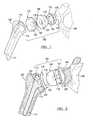
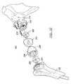
- FIG. 1is an exploded view of an embodiment of an implant assembly according to the invention, shown in a traditional shoulder arthroplasty;
- FIG. 2is an exploded view of an embodiment of an implant assembly according to the invention, shown in a reverse shoulder arthroplasty;
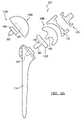
- FIGS. 3A-3Dare side views of embodiments of an adaptor according to the present invention.
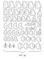
- FIGS. 4A-4Eare side views of embodiments of a cup according to the present invention.
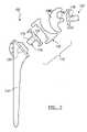
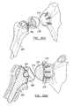
- FIG. 5Ais an exploded view of an embodiment of an implant assembly according to the invention, shown in a traditional shoulder arthroplasty and with alternative heads and humeral adaptors;
- FIG. 5Bis an exploded view of an embodiment of an implant assembly according to the invention, shown in a reverse shoulder arthroplasty;
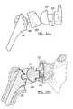
- FIG. 6Ais an exploded view of an embodiment of an implant assembly according to the invention, shown in a traditional shoulder arthroplasty;
- FIG. 6Bis an exploded view of an embodiment of an implant assembly according to the invention, shown in a reverse shoulder arthroplasty;
- FIG. 7is an exploded view of an embodiment of an implant assembly according to the invention, shown in a reverse shoulder arthroplasty;
- FIG. 8is an embodiment of a assembly of components for shoulder arthroplasty according to the invention.
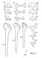
- FIGS. 9A-9Care side views of embodiments of heads according to the invention.
- FIGS. 10A-10Care side views of embodiments of adaptors corresponding to the heads of FIGS. 9A-9C ;
- FIGS. 11A-11Care side views of embodiments of head bearings
- FIG. 12is an exploded view of an embodiment of an implant assembly according to the invention, shown in a traditional shoulder arthroplasty;
- FIG. 13is an exploded view of an embodiment of an implant assembly according to the invention, shown in a traditional shoulder arthroplasty without a humeral stem;
- FIG. 14is an exploded view of an embodiment of an implant assembly according to the invention, shown in a reverse shoulder arthroplasty without a humeral stem;
- FIG. 15is an exploded view of an embodiment of modular adaptor, shown with glenoid and humeral stems;
- FIG. 16is an exploded view of an embodiment of modular adaptor; shown with glenoid and humeral stems;
- FIG. 17represents a perspective exploded view of an alternate shoulder prosthetic
- FIGS. 18A-18Crepresent side views of the shoulder prosthetic shown in FIG. 17 ;
- FIGS. 19A and 19Brepresent side views of an alternate shoulder assembly
- FIGS. 20A and 20Brepresent side views of an alternate shoulder assembly
- FIGS. 21A and 21Brepresent side views of an alternate shoulder assembly
- FIGS. 22A and 22Brepresent side views of an alternate shoulder assembly
- FIGS. 23A and 23Bdepict the assembly of a humeral component shown in the joint prosthetic shown in FIGS. 20A and 20B ;
- FIGS. 24A-26Brepresent views of the glenoid component shown in FIGS. 17-21B ;
- FIGS. 27A-29Brepresent bearings used in the assemblies shown in FIGS. 18A , 18 B, 20 A and 20 B;
- FIGS. 30A-32represent head components shown in FIGS. 17-22B ;
- FIGS. 33A-33Crepresent the adaptor shown in FIGS. 17-23B ;
- FIG. 34represents a kit of components shown in FIGS. 17-33 ;
- FIG. 35represents the humeral implant for a reverse shoulder prosthetic
- FIGS. 36-40represent an implant shown in FIG. 35 utilizing an alternate head
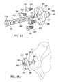
- FIGS. 41A-41Drepresent glenoid fixation components
- FIGS. 42A and 42Brepresent a humeral body portion shown in FIGS. 35-40 .
- FIG. 43represents a coupling glenoid tray according to the present teachings.
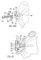
- FIGS. 44A and 44Brepresent the insertion of the tray shown in FIG. 43 ;
- FIG. 45represents a cross-sectional view of an implanted tray shown in FIG. 43 ;
- FIG. 46represents the coupling of an articulating head to the tray shown in FIG. 45 ;
- FIG. 47represents the coupling of a glenoid prosthetic to the tray shown in FIG. 45 ;
- FIGS. 48 and 49represent an alternate method to fix the tray of FIG. 43 to a prepared glenoid
- FIGS. 50 and 51represent alternate mechanisms to couple a head to the tray of FIG. 43 ;
- FIG. 52represents an alternate method of implanting the tray shown in FIG. 43 ;
- FIG. 53represents an exploded view of a prosthetic shoulder assembly
- FIG. 54represent an alternate shoulder prosthesis.
- FIGS. 1 and 2there is shown an embodiment of an implant assembly 100 for a total shoulder joint replacement.
- the implant assembly 100is configured to be implanted between a resected humerus 102 and a glenoid cavity (“glenoid”) 104 of a scapula 106 in one of two ways, i.e., in a traditional arthroplasty depicted in FIG. 1 , or in a reverse arthroplasty depicted in FIG. 2 , by selecting and/or reconfiguring appropriately the components of the implant assembly 100 .
- the implant assembly 100includes a head 108 , a cup 110 , and an adaptor 112 .
- the implant assembly 100may also include a humeral stem 114 that has a proximal end 115 and a distal end 117 .
- FIGS. 5A , 6 A, 12 , and 13are shown in FIGS. 5A , 6 A, 12 , and 13 for traditional shoulder replacement, and in FIGS. 5B , 6 B, 7 and 14 for reverse shoulder replacement.
- FIGS. 3A-3D , 4 A- 4 E, 9 A- 9 C, 10 A- 10 C, and 11 A- 11 Cshow representative embodiments of various components.
- FIGS. 15 and 16show embodiments of a modular adaptor 113 .
- FIG. 8shows an embodiment of a component assembly (kit) for shoulder replacement 800 showing different sizes of representative components. It should be understood that the component assembly 800 in FIG. 8 is only illustrative of the inclusion of different sizes of each component and it is not limited by the type of components actually shown.
- the component assembly 800may include different sizes of each of the heads 108 shown in FIGS. 9A-9C , different types and sizes of adaptors 112 , different sizes and types of cups 110 , etc.
- Like reference numeralsrefer to like components. When clarity requires differentiating between different embodiments of the same component, an alphabetic character is attached to the reference numeral.
- the head 108is referenced as head 108 A and head 108 B to distinguish between two different head embodiments, as shown in FIG. 5A .
- the head 108is bounded by a convex surface 116 , which may be, for example, a hemispherical surface, and a base 118 , which may be a substantially planar surface.
- the base 118may be modularly connected to the head 108 .
- a female taper 120 with tapered inner walls 122extends from the base 118 into the head 108 .
- the convex surface 116 of the head 108is shaped to articulate with a concave surface 124 of the cup 110 to allow for shoulder joint movement. Such articulation may be centered or eccentric.
- FIGS. 9A-9CThis and other embodiments of the head 108 are shown in FIGS. 9A-9C .
- the head 108has a male taper 140 .
- the head 108has a female taper 142 .
- the cup 110may include a back surface 126 that may be configured to be selectively attached to the humeral stem 114 in reverse shoulder arthroplasty, or to the resected glenoid 104 in the traditional shoulder arthroplasty.
- the cup 110may be chosen from a number for available cups, such as those shown in FIGS. 4A-4D , some of which are better suited to either reverse shoulder arthroplasty or traditional shoulder arthroplasty.
- the back surface 126 of the cup 110may be a substantially planar surface which can be attached with cement or with mechanical fasteners, such as screws, to the humeral stem 114 or to the appropriately resected glenoid 104 .
- the back surface 126may be slightly convex.
- the back surface 126may include a number of pegs 127 for attachment to the glenoid 104 .
- the cup 110may include a male taper 121 which is received in a corresponding female taper 123 of the proximal end 115 of the humeral stem 114 .
- FIG. 4Eshows a bearing 192 of a modular cup 110 that has a concave surface 124 and a female taper 144 adapted to receive a modular glenoid stem 130 or modular humeral stem 136 , such as those shown in FIGS. 15 and 16 in connection with the modular adaptor 113 .
- the bearing 192may also be used with the embodiments of FIGS. 13 and 14 , as is described below.
- the modular adaptor 113may include a body 150 with a male taper 152 and a female taper 154 .
- the female taper 154is adapted to receive a glenoid stem 134 for the reverse shoulder arthroplasty and a humeral stem 136 for the traditional shoulder arthroplasty.
- the male taper 152is adapted to be received in the female taper 142 of the embodiment of the head 108 shown in FIG. 9B or in the female taper 120 of the embodiment of the head 108 shown in FIG. 9C , for example.
- the adaptor 112may be modular, such as the adaptor 113 of FIGS. 15 and 16 , or a monolithic adaptor.
- the adaptor 112may be a single, one and the same, adaptor that can be used selectively in both the traditional and the reverse shoulder arthroplasty, or it can be chosen from a number of available adaptors of an assembly of components, such as those shown in FIGS. 3A-3D , depending on which arthroplasty procedure is to be performed.
- Some of these adaptors 112such as, for example, the adaptor shown in FIG. 3C , may be specifically configured for use with reverse arthroplasty, because they incorporate the glenoid stem 134 , either modularly or monolithically.
- the adaptor 112may include an adaptor tray 128 and an extension or male taper 130 that can be press-fitted into the female taper 120 of the head 108 .
- the tray 128is attached to the proximal end of the humeral stem 114 , as shown in FIG. 1 .
- the tray 128is attached to the glenoid 104 , as shown in FIG. 2 .
- the tray 128may include a curved portion 132 shaped to conform to a portion of the glenoid 104 . It may also include the glenoid stem 134 , which is inserted into the glenoid 104 .
- the adaptormay be attached to the glenoid 104 with fasteners, such as screws.
- the tray 128may also be substantially planar. It will be appreciated, however, that other shapes, in addition to those shown in FIGS. 3A-3D , are possible for the tray 128 depending, for example, on the various ways the tray 128 is be attached to the humerus 102 , to the humeral stem 114 , or to the glenoid 104 .
- the adaptor 112may be modular, such that the male taper 130 , the tray 128 and the glenoid stem 134 are all separate components interconnected though fasteners, such as screws, or other type of connectors, including male-female tapers as illustrated in FIGS. 15 and 16 .
- the adaptors 112 , 112 A shown in FIGS. 3D and 5Ainclude a male taper 148 which can be received in the female taper of 120 of the head 108 , 108 A, and a male taper 160 which can be received in the female taper 123 of the humeral stem 114 .
- the cup 110may be replaced by a bearing base 170 , which is also an adaptor, and a bearing 172 that can be fitted to the base 170 .
- the bearing base 170has a male taper 174 configured to be received in the female taper 123 of the humeral stem 114 . Examples of bearings 172 with symmetric or non-symmetric and eccentric bearing surfaces 176 are shown in FIGS. 11A-11C .
- the bearing base 170includes a female taper 178 adapted to receive the male taper 140 of the head 108 B.
- the cup 110may be replaced by a bearing 180 that is fitted in a bearing base 182 with mating male taper 184 and female taper 186 , or with a bearing 180 that includes only a liner 188 .
- the bearing base 182may include a modular or integral glenoid stem 190 .
- the implant assembly 100may be used as follows.
- the humeral stem 114is inserted in the resected humerus 102 .
- the adaptor 112is attached to the head 108 by inserting the male taper 130 into the female taper 120 .
- the cup 110is attached to the glenoid 104 , and the adaptor 112 is attached to the proximal end 115 of the humeral stem 114 , such that the convex surface 116 of head 108 articulates with the concave surface 124 of the cup 110 .
- the cup 110is attached to the proximal end 115 of the stem humeral 114 and the adaptor 112 is attached to the resected glenoid 104 such that the convex surface 116 of head 108 articulates with the concave surface 124 of the cup 110 .
- the same adaptor 112can be used for both the traditional and the reverse shoulder arthroplasty procedures, glenoid-specific adaptors 112 may be chosen, either as integral components or built from modular parts that include male tapers 130 , trays 128 and glenoid stems 134 .
- the individual components of the implant assembly 100may be made using a variety of materials, including metal and plastic.
- the head and the stemmay be made of metallic material, such as a cobalt chrome alloy, for example. Porous coating may be provided for the proximal end of the stem.
- the cupmay be made of polyethylene or metal or a combination thereof, such as polyethylene bearing or lining and metal base.
- the adaptorcan be typically made of metal.
- FIGS. 5A , 5 B, 6 A, 6 B, 7 , and 12 - 14Other exemplary embodiments are illustrated in FIGS. 5A , 5 B, 6 A, 6 B, 7 , and 12 - 14 .
- the male taper 140 of the head 108 Bcan also be inserted directly into the female taper 123 of the humeral stem 123 .
- an adaptor 112 B having a male taper 162 and a female taper 164may be provided.
- the adaptor 112 Bmay be also used in the embodiments shown in FIGS. 5B , 6 A, and 6 B.
- the male taper 148 of the adaptor 112 Acan be received in the female taper 120 of the head 108 for the traditional shoulder arthroplasty shown in FIG. 13 , and in the female taper 144 of the bearing 192 for the reverse arthroplasty shown in FIG. 14 .
- the male taper 130 of the glenoid adaptor 112may be received in the female taper 120 of the head 108 for the reverse shoulder arthroplasty, and in the female taper 144 of the bearing 192 for the traditional shoulder arthroplasty.
- FIG. 17represents a perspective exploded view of an alternate shoulder prosthetic 200 .
- the prosthetic 200has a humeral stem 202 which is mated to a bearing 208 that interfaces with a head portion 210 .
- the head portion 210is coupled to a prepared glenoid 214 .
- the humeral stem 202has a coupling portion 204 which is configured to mate with a coupling taper 206 ′ on adaptor 206 .
- the adaptor 206has a coupling taper or taper lock connection 207 which is configured to couple to a corresponding coupling taper 211 disposed on a surface of the bearing 208 .
- the bearing 208has a bearing surface 209 which articulates with the articulating surface of the head 210 .
- FIGS. 18A and 18Brepresent a side view of the prosthetic 200 shown in FIG. 17 .
- a second adaptor 206is disposed between head 210 and the glenoid component 212 .
- the adaptor 206is configured to interface with a coupling taper 222 defined within the glenoid bearing member 212 .
- the coupling taper 222can be either a male or a female taper lock connection configured to mate with an appropriate taper on the head 210 (see FIG. 18C ).
- the glenoid bearing member 212is coupled to the prepared glenoid 214 using a plurality of fixation screws 216 .
- the adaptors 206optionally can have a pair of locking tapered members which are off axis from each other, allowing a physician to rotate the offset to align the components within the joint to increase the range of motion of the prosthetic 200 .
- the rotation of the adaptors 206allows for the radial, rotational and angular positioning of the head and cup members.
- at least some of the componentscan be used in a traditional arthroplasty.
- the bearing member 208 ′can be coupled directly to the coupling portion 204 of the humeral stem 202 .
- the bearing 208 ′can have a male coupled taper 206 or a female coupling taper.
- the use of an adaptor 206 having an offset tapered stemcan allow for relative movement of the articulating head 210 with respect to the bearing 208 .
- the articulating head 210can have a stem 213 which is configured to couple with a female locking taper 222 within the glenoid component 212 .
- the use of an offset adaptor 206 located between the bearing 208 and the coupling portion 204 of the humeral stem 202allows for relative displacement of the bearing surface 209 of the bearing member 208 with respect to the head portion 210 . Furthermore, by removing the adaptor 206 , the size of the joint can be reduced.
- the bearing 208can be directly coupled to a coupling portion 204 of the stem 202 .
- the head 210can be coupled directly to the glenoid component 212 to reduce the overall size of the joint.
- the direct coupling of the componentsis accomplished by using locking tapers or fixation members such as threaded fasteners or adhesive.
- a head 218can be directly coupled to the glenoid 214 .
- This head 218can be directly coupled to the glenoid 214 using a plurality of bone fixation screws 216 coupled to the head 218 .
- an attachment tray(not shown) can be used to couple the head to the prepared glenoid.
- the bearing surface 219 of the head 218can have a varying radius of curvature over its surface. In this regard, the radius of curvature can be specifically design to interface with the bearing surface 209 of the bearing member 208 to increase the range of motion while reducing chances of dislocation of the joint.
- FIGS. 23A and 23Brepresent the coupling of the bearing member to the humeral component 202 .
- the adaptor 206is coupled to coupling portion 204 of the stem.
- a male taper lock connection 226is disposed within the coupling portion 204 .
- the bearing 208is then coupled to a male taper lock connection 228 disposed on the adaptor 226 .
- a trialing adaptor 206can be used to allow the placement of the bearing member 208 .
- the trailing headis non-fixably coupled to the stem and rotated to place the cup in its proper location.
- a regular adaptor 206is fixably coupled the stem using an impactor as is known.
- FIGS. 24A-26Brepresent alternate views of the glenoid member 212 .
- the glenoid member 212has a first curved coupling surface 230 which is configured to be mated to a curved surface on the prepared glenoid 214 . Additionally, the glenoid 212 has a outward facing surface 232 which is generally opposite to the coupling surface 230 . Disposed on the outward surface 232 is a boss portion 236 which defines an exterior fixation taper. Additionally, the boss 236 defines the interior taper 222 which is configured to fixedly accept a male taper of the adaptor 206 . Defined through the glenoid component is a plurality of bone fixation holes 234 . The bone fixation holes 234 are angled with respect to each other to provide enhanced fixation of the glenoid member 212 to the prepared glenoid 214 .
- FIGS. 27A-29Brepresent alternate bearing members 208 .
- the coupling taper 240is configured to be mated either with an adaptor 206 or with the humeral fixation member 204 .
- Defined on a bearing side 239 of the adaptor 208is the bearing surface 209 .
- the bearing surface 209can vary in curvature to maximize the articulation of the head on the bearing surface 208 while minimizing the possibility of dislocation of the head 210 from the bearing 208 .
- the surface 209can have a profile which varies with respect to the bearing side 239 or the coupling surface 238 .
- FIGS. 30A-32represent alternate heads 210 that can optionally be used in the shoulder prosthetic 200 .
- a fixation member 248Disposed on a coupling side of the head 210 is a fixation member 248 which can be a female or male coupling taper.
- the head 210can further have an extended articulating surface 250 which can vary in radius of curvature and in length.
- FIGS. 33A-33Crepresent adaptors 206 having varying offsets for adjusting the location of the head or bearing member within the joint. It is envisioned the adaptors 206 additionally can have varying heights which allow for varying displacement of the head from the glenoid.
- FIG. 34represents the kit of bearing, head, and adaptor members utilized to construct the humeral prosthetic. It is envisioned that this kit can additionally have varying stems and fixation devices such as screws.
- FIG. 35represents an alternate reverse humeral prosthetic 260 for use with a large segment humeral resection.
- the modular humeral prosthetic 260has a humeral body portion 262 , a base member 264 , and a fixation stem 266 .
- the base membercan annularly support a soft tissue fixation member 268 .
- the humeral body portion 262has a concave bearing surface 270 configured to articulate with a head member in a reverse shoulder. It is envisioned that this concave bearing surface 270 can be a bio-compatible polymer, metal or ceramic.
- the concave bearingcan be coupled to a modular bearing head 290 which is mated with a coupling taper 292 defined in the humeral body portion 262 .
- FIGS. 36-38depict a side view of an implanted humeral prosthetic 260 .
- Each humeral prosthetic 260is mated with a head 272 that is coupled to the prepared glenoid 214 .
- the head 272 of the reverse shoulder prostheticcan be coupled to the prepared glenoid 214 using a large mating screw 294 .
- the head 272can have extended articulating surface 274 to allow for proper articulation of the joint.
- the head 272can have a coupling surface 215 which is generally perpendicular or angled to the fixation screw 294 .
- FIGS. 38 and 39represent the coupling of the head portion 272 of the prosthetic to the glenoid 214 . Shown is the tray 276 which is inserted into an aperture 277 defined within a coupled glenoid 288 . Next, a fixation screw is used to couple the tray 276 to the prepared glenoid 288 . A head 272 is oriented and then snapped or fixed to the tray 276 .
- the tray 276has a retaining flange 284 and a bone screw accepting aperture 280 .
- Disposed on a coupling surface of the tray 276is a non-threaded extended region 286 which measures in length greater than 6 millimeters. It has been found that having the extended portion 286 having a length of greater than 6 millimeters allows for the proper coupling of the tray 276 without stress concentration failures in the mating fastener.
- the extended portion 286can have a counter bore 287 , which is configured to accept a head of the bone engaging fastener 282 .
- FIGS. 42A and 42Brepresent the humeral body portion 262 .
- the humeral body portion 262has a concave bearing member 272 .
- the concave bearing member 272can be integral with the monolithic humeral body portion 262 or may be coupled to a bearing member 290 .
- the bearing member 290can be coupled to a fixation member 294 within the humeral body portion 262 .
- the humeral body portion 262further has a locking member 292 which can either be a male or female taper to couple the humeral body portion 262 to the base member 264 .
- FIG. 43represents an alternate tray 300 of the present teachings. Shown is a central fixation screw 302 configured to mate with a central fixation hole 304 defined in a tray plate 306 .
- the central fixation screw 302has a threaded body 308 having a bone engaging tip 310 and associated coupling screw thread 312 .
- the screw 302further has a head 314 configured to be removably coupled to a tray central screw bearing surface 335 .
- Included radially about the central fixation hole 304are a plurality of bone screw accepting apertures 316 .
- four bone screw accepting apertures 316can have tapered inner surfaces 317 which are defined about the central fixation hole 304 .
- the screw accepting apertures 316are configured to optionally accept cortical bone engaging screws 320 .
- the cortical bone engaging screws 320can have a conical thread exterior surface 322 .
- Associated with the conical exterior surface 322can be conical heads 324 which are configured to engage a conical inner surface 317 of the screw accepting apertures 316 .
- the plate tray 306has a bone engaging surface 326 having a hollow tapered peg 328 .
- the peg 328defines a through bore 330 linearly aligned with the central fixation hole 304 .
- the tapered peg 328can have an exterior treatment to enhance the coupling of the hollowed tapered peg 328 with a prepared glenoid 331 .
- FIGS. 44A and 44Bdepict the coupling of a tray 300 to a prepared glenoid.
- an aperture 329is formed in the prepared glenoid to receive the peg 328 .
- the tray 300can be rotated to position the apertures 316 in locations where the bone tissue is most advantageous for coupling of the critical bone screws.
- the central fixation screw 302is passed through the central fixation hole 304 and through the through bore 330 of the hollowed tapered peg 328 .
- the hollow tapered peg 328has a first portion 332 having a first exterior surface with a first diameter and a second portion 333 having a second diameter smaller than the first diameter.
- the through bore 330includes a seat portion 335 configured to function as a bearing surface for engagement with the head 314 of the central screw 302 .
- the location of the seated portion 335is preferably located about 6 millimeters from the coupling surface 334 of the tray 300 . This offset is configured to reduce bending moments and loading on the fixation screw 302 .
- the through bore 330further includes a coupling interior taper 337 which is configured to engageably receive a corresponding fixation taper 338 .
- the plurality of bone engaging screws 320can be inserted into the bone screw accepting apertures 316 .
- the tapered head surfaces 324 of the bone engaging screws 320can engage the tapered inner surfaces of the bone screw accepting apertures 316 .
- the center lines of the plurality of bone screw accepting apertures 316may be parallel to the center line of the through bore 330 . Additionally, the center line of bone accepting apertures 316 can intersect or skew with respect to the centerline of the through bore 330 .
- the head 324 or glenoid component 326can have a male coupling taper 338 .
- the head 324 and glenoid component 326can have a polymer, ceramic or biocompatible metal articulating surface disposed on a metal support.
- the tray 300can be coupled to the prepared glenoid using only the plurality of bone engaging screws 320 .
- the central fixation screws 302may not be used.
- the peg 328can be solid.
- the platecan take the form of the plate 170 of FIG. 5 having a plurality of bone screw accepting apertures 316 .
- a coupling mechanism 330can be positioned between the head 324 and the tray 300 .
- the head 332can have a countersink 334 configured to encapsulate the tray 300 to place the articulating head 324 close to the resected glenoid.
- the glenoid surfacecan have a countersink 336 which can encapsulate the plate 306 of tray 300 .
- the adaptor 340can be used to offset a head with respect to the central screw member 302 . It is envisioned that this offset adaptor 340 can be used with either a head 324 , as shown, or a glenoid component (not shown) to perform either a reverse or regular total shoulder replacement. In this regard, during implantation, any of the aforementioned methods can be used to position a head at the scapula or a cup member. Additionally, previously detailed offsetting intermediate members can be used to change the positions of any of the articulating members within a joint.
- a humeral stem 114can be placed within the medullary canal of a humerus 102 .
- the base 170coupled to the female taper 123 of the humeral stem 114 can be the base 170 with corresponding female coupling taper 178 .
- Disposed about a periphery of the coupling taper 178can be at least one screw accepting aperture 316 which accepts a bone engaging screw or fastener 320 .
- Either the baseplate 170 or the screw accepting aperture 316can define a fastener head engaging surface.
- the base 170can be coupled to the female taper 123 .
- the base 170Prior to fixably coupling the base 170 to the stem 114 , the base 170 can be rotated into position so as to maximize the retention by the bone fixation fastener 320 .
- Fasteners 320can then be selectively coupled to bone which is radially disposed about the coupling portion 3432 of the stem 114 .
Landscapes
- Health & Medical Sciences (AREA)
- Orthopedic Medicine & Surgery (AREA)
- Cardiology (AREA)
- Oral & Maxillofacial Surgery (AREA)
- Transplantation (AREA)
- Engineering & Computer Science (AREA)
- Biomedical Technology (AREA)
- Heart & Thoracic Surgery (AREA)
- Vascular Medicine (AREA)
- Life Sciences & Earth Sciences (AREA)
- Animal Behavior & Ethology (AREA)
- General Health & Medical Sciences (AREA)
- Public Health (AREA)
- Veterinary Medicine (AREA)
- Prostheses (AREA)
Abstract
Description
Claims (13)
Priority Applications (3)
| Application Number | Priority Date | Filing Date | Title |
|---|---|---|---|
| US12/390,652US8070820B2 (en) | 2003-10-08 | 2009-02-23 | Shoulder implant assembly |
| US13/269,772US9283083B2 (en) | 2003-10-08 | 2011-10-10 | Shoulder implant assembly |
| US15/068,717US20160262902A1 (en) | 2003-10-08 | 2016-03-14 | Shoulder implant assembly |
Applications Claiming Priority (3)
| Application Number | Priority Date | Filing Date | Title |
|---|---|---|---|
| US10/680,924US7175663B1 (en) | 2003-10-08 | 2003-10-08 | Shoulder implant assembly |
| US11/234,743US8062376B2 (en) | 2002-07-10 | 2005-09-23 | Shoulder implant assembly |
| US12/390,652US8070820B2 (en) | 2003-10-08 | 2009-02-23 | Shoulder implant assembly |
Related Parent Applications (1)
| Application Number | Title | Priority Date | Filing Date |
|---|---|---|---|
| US11/234,743Continuation-In-PartUS8062376B2 (en) | 2002-07-10 | 2005-09-23 | Shoulder implant assembly |
Related Child Applications (1)
| Application Number | Title | Priority Date | Filing Date |
|---|---|---|---|
| US13/269,772DivisionUS9283083B2 (en) | 2003-10-08 | 2011-10-10 | Shoulder implant assembly |
Publications (2)
| Publication Number | Publication Date |
|---|---|
| US20090192621A1 US20090192621A1 (en) | 2009-07-30 |
| US8070820B2true US8070820B2 (en) | 2011-12-06 |
Family
ID=46332134
Family Applications (3)
| Application Number | Title | Priority Date | Filing Date |
|---|---|---|---|
| US12/390,652Expired - LifetimeUS8070820B2 (en) | 2003-10-08 | 2009-02-23 | Shoulder implant assembly |
| US13/269,772Expired - Fee RelatedUS9283083B2 (en) | 2003-10-08 | 2011-10-10 | Shoulder implant assembly |
| US15/068,717AbandonedUS20160262902A1 (en) | 2003-10-08 | 2016-03-14 | Shoulder implant assembly |
Family Applications After (2)
| Application Number | Title | Priority Date | Filing Date |
|---|---|---|---|
| US13/269,772Expired - Fee RelatedUS9283083B2 (en) | 2003-10-08 | 2011-10-10 | Shoulder implant assembly |
| US15/068,717AbandonedUS20160262902A1 (en) | 2003-10-08 | 2016-03-14 | Shoulder implant assembly |
Country Status (1)
| Country | Link |
|---|---|
| US (3) | US8070820B2 (en) |
Cited By (41)
| Publication number | Priority date | Publication date | Assignee | Title |
|---|---|---|---|---|
| US20120150308A1 (en)* | 2003-07-22 | 2012-06-14 | Avanta Orthopaedics, Llc | Prosthetic wrist implant |
| US8545511B2 (en) | 2007-10-12 | 2013-10-01 | Howmedica Osteonics Corp. | Expandable reverse shoulder trial |
| WO2013110031A3 (en)* | 2012-01-20 | 2014-02-13 | Shoulder Options, Inc. | Humeral head prosthesis |
| US8663334B2 (en) | 2012-05-31 | 2014-03-04 | Howmedica Osteonics Corp. | Lateral entry insert for cup trial |
| WO2014047155A1 (en) | 2012-09-21 | 2014-03-27 | Zimmer, Inc. | Shoulder implant system |
| US20140294488A1 (en)* | 2012-03-01 | 2014-10-02 | Bayerische Motoren Werke Aktiengesellschaft | Fixing Element, Method for Welding a Fixing Element to a Component and Component Connection |
| US8906102B2 (en)* | 2012-05-31 | 2014-12-09 | Howmedica Osteonics Corp. | Lateral entry insert for cup trial |
| US9078758B2 (en) | 2011-05-12 | 2015-07-14 | Howmedica Osteonics Corp. | Wrist implant for carpal hemiarthroplasty |
| US9283083B2 (en) | 2003-10-08 | 2016-03-15 | Biomet Manufacturing, Llc | Shoulder implant assembly |
| US9421106B2 (en) | 2011-12-07 | 2016-08-23 | Howmedica Osteonics Corp. | Reverse shoulder baseplate with alignment guide for glenosphere |
| US9498345B2 (en) | 2011-02-01 | 2016-11-22 | Tornier Sas | Glenoid implant for a shoulder prosthesis, and surgical kit |
| US9597190B2 (en) | 2015-01-15 | 2017-03-21 | DePuy Synthes Products, Inc. | Modular reverse shoulder orthopaedic implant and method of implanting the same |
| US9629725B2 (en) | 2014-01-03 | 2017-04-25 | Tornier, Inc. | Reverse shoulder systems and methods |
| US9681960B2 (en) | 2014-05-16 | 2017-06-20 | Howmedica Osteonics Corp. | Guides for fracture system |
| US10034759B2 (en) | 2012-10-29 | 2018-07-31 | Tornier Orthopedics Ireland Ltd. | Reverse shoulder implants |
| USD835276S1 (en) | 2015-09-11 | 2018-12-04 | United Orthopedic Corporation | Keeled glenoid |
| US10172714B2 (en) | 2016-02-28 | 2019-01-08 | Consortium Of Focused Orthopedists, Llc | Shoulder arthroplasty implant system |
| US10390972B2 (en) | 2016-01-15 | 2019-08-27 | Howmedica Osteonics Corp. | Humeral trial adaptor |
| US10433969B2 (en) | 2013-12-30 | 2019-10-08 | United Orthopedic Corp. | Arthroplasty implants and methods for orienting joint prosthesis |
| US20190314161A1 (en)* | 2015-04-07 | 2019-10-17 | Zimmer, Inc. | Convertible glenoid |
| US20200030108A1 (en)* | 2018-07-24 | 2020-01-30 | DePuy Synthes Products, Inc. | Baseplate of a modular shoulder joint prosthesis and related methods for implanting the same |
| US10548737B2 (en) | 2011-10-31 | 2020-02-04 | Tornier Orthopedics Ireland Ltd. | Reverse shoulder prostheses with anti-rotation features |
| US10575968B2 (en) | 2014-05-16 | 2020-03-03 | Howmedica Osteonics Corp. | Guides for fracture system |
| US10610367B2 (en) | 2015-09-11 | 2020-04-07 | United Orthopedic Corp. | Arthroplasty components |
| US10722374B2 (en) | 2015-05-05 | 2020-07-28 | Tornier, Inc. | Convertible glenoid implant |
| WO2020219962A1 (en)* | 2019-04-25 | 2020-10-29 | Encore Medical, L.P. (D/B/A/ Djo Surgical) | Glenoid implant systems and methods of using the same |
| US10849692B2 (en)* | 2016-06-17 | 2020-12-01 | Zimmer, Inc. | System and method for intraoperative surgical planning |
| US10898336B2 (en) | 2006-03-21 | 2021-01-26 | Tornier, Inc. | Femoral and humeral stem geometry and implantation method for orthopedic joint reconstruction |
| US11160661B2 (en) | 2009-12-14 | 2021-11-02 | Tornier Sas | Shoulder prosthesis glenoid component |
| US11197764B2 (en) | 2017-03-31 | 2021-12-14 | Howmedica Osteonics Corp. | Modular humeral head |
| US11369479B2 (en) | 2016-08-24 | 2022-06-28 | Howmedica Osteonics Corp. | Humeral head implant system |
| US11432935B2 (en)* | 2020-04-01 | 2022-09-06 | Arthrex, Inc. | Orthopaedic implants including peripheral aperture arrangements |
| WO2022232517A1 (en)* | 2021-04-29 | 2022-11-03 | Raphael S.F. Longobardi, Llc | Modular glenoid component for use in a universal shoulder prosthesis system |
| US11564802B2 (en) | 2017-10-16 | 2023-01-31 | Imascap Sas | Shoulder implants and assembly |
| US11571310B2 (en) | 2019-04-03 | 2023-02-07 | Catalyst Orthoscience Inc. | Stemmed implant |
| US11779471B2 (en) | 2019-08-09 | 2023-10-10 | Howmedica Osteonics Corp. | Apparatuses and methods for implanting glenoid prostheses |
| US11833055B2 (en) | 2016-02-28 | 2023-12-05 | Integrated Shoulder Collaboration, Inc. | Shoulder arthroplasty implant system |
| US11931264B2 (en) | 2018-10-02 | 2024-03-19 | Howmedica Osteonics Corp. | Modular humeral head |
| US12268610B2 (en) | 2020-05-07 | 2025-04-08 | Howmedica Osteonics Corp. | Stemless metaphyseal humeral implant |
| US12370052B2 (en) | 2018-10-02 | 2025-07-29 | Howmedica Osteonics Corp. | Modular humeral head |
| US12396862B2 (en) | 2019-05-13 | 2025-08-26 | Howmedica Osteonics Corp. | Glenoid baseplate and implant assemblies |
Families Citing this family (103)
| Publication number | Priority date | Publication date | Assignee | Title |
|---|---|---|---|---|
| US6942699B2 (en) | 2001-07-11 | 2005-09-13 | Biomet, Inc. | Shoulder prosthesis |
| US8795379B2 (en)* | 2001-07-11 | 2014-08-05 | Biomet Manufacturing, Llc | Variable prosthesis |
| US20040162619A1 (en) | 2001-08-27 | 2004-08-19 | Zimmer Technology, Inc. | Tibial augments for use with knee joint prostheses, method of implanting the tibial augment, and associated tools |
| US7892288B2 (en) | 2001-08-27 | 2011-02-22 | Zimmer Technology, Inc. | Femoral augments for use with knee joint prosthesis |
| US20030065397A1 (en) | 2001-08-27 | 2003-04-03 | Hanssen Arlen D. | Prosthetic implant support structure |
| US8062376B2 (en)* | 2002-07-10 | 2011-11-22 | Biomet Manufacturing Corp. | Shoulder implant assembly |
| US8388624B2 (en) | 2003-02-24 | 2013-03-05 | Arthrosurface Incorporated | Trochlear resurfacing system and method |
| US8778028B2 (en) | 2005-02-25 | 2014-07-15 | Shoulder Innovations, Inc. | Methods and devices for less invasive glenoid replacement |
| US8007538B2 (en) | 2005-02-25 | 2011-08-30 | Shoulder Innovations, Llc | Shoulder implant for glenoid replacement |
| US20230080207A1 (en) | 2005-02-25 | 2023-03-16 | Shoulder Innovations, Inc. | Methods and devices for less invasive glenoid replacement |
| US9358029B2 (en) | 2006-12-11 | 2016-06-07 | Arthrosurface Incorporated | Retrograde resection apparatus and method |
| US9545311B2 (en) | 2009-03-05 | 2017-01-17 | Tornier, Inc. | Glenoid implant anchor post |
| US10945743B2 (en) | 2009-04-17 | 2021-03-16 | Arthrosurface Incorporated | Glenoid repair system and methods of use thereof |
| WO2010121250A1 (en) | 2009-04-17 | 2010-10-21 | Arthrosurface Incorporated | Glenoid resurfacing system and method |
| US8246687B2 (en) | 2009-11-18 | 2012-08-21 | Biomet Manufacturing Corp. | Shoulder prosthetic |
| US9421109B2 (en) | 2010-01-13 | 2016-08-23 | Jcbd, Llc | Systems and methods of fusing a sacroiliac joint |
| WO2014015309A1 (en) | 2012-07-20 | 2014-01-23 | Jcbd, Llc | Orthopedic anchoring system and methods |
| US9333090B2 (en) | 2010-01-13 | 2016-05-10 | Jcbd, Llc | Systems for and methods of fusing a sacroiliac joint |
| US9381045B2 (en) | 2010-01-13 | 2016-07-05 | Jcbd, Llc | Sacroiliac joint implant and sacroiliac joint instrument for fusing a sacroiliac joint |
| CA3002234C (en) | 2010-01-13 | 2020-07-28 | Jcbd, Llc | Sacroiliac joint fixation fusion system |
| EP2542165A4 (en) | 2010-03-05 | 2015-10-07 | Arthrosurface Inc | Tibial resurfacing system and method |
| US8313531B2 (en)* | 2010-03-08 | 2012-11-20 | Hip Innovation Technology Llc | Interlocking reverse hip prosthesis and method |
| US8454702B2 (en) | 2011-01-20 | 2013-06-04 | Biomet Manufacturing Corp. | Reverse shoulder prosthetic |
| AU2012214581A1 (en)* | 2011-02-07 | 2013-08-15 | Exactech, Inc. | Adjustable reverse shoulder prostheses |
| US20120253467A1 (en)* | 2011-02-13 | 2012-10-04 | Mark Frankle | Shoulder Arthroplasty Systems and Configurations for Components Thereof |
| US8591591B2 (en)* | 2011-05-25 | 2013-11-26 | Biomet Manufacturing, Llc | Spring base glenosphere |
| EP2720628B1 (en) | 2011-06-17 | 2021-08-11 | Jcbd, Llc | Sacroiliac joint implant system |
| ES2592222T3 (en) | 2011-08-08 | 2016-11-28 | Hip Innovation Technology Llc | Orthopedic instrument and system to implant an acetabular cup |
| ES2558460T3 (en) | 2011-08-13 | 2016-02-04 | Hip Innovation Technology Llc | Acetabular locking screws and their combination with an acetabular cup for inverted hip |
| US8702804B2 (en) | 2011-12-02 | 2014-04-22 | Biomet Manufacturing, Llc | Variable prosthesis |
| US9439768B2 (en) | 2011-12-08 | 2016-09-13 | Imds Llc | Glenoid vault fixation |
| US9414927B2 (en) | 2011-12-08 | 2016-08-16 | Imds Llc | Shoulder arthroplasty |
| EP2804565B1 (en) | 2011-12-22 | 2018-03-07 | Arthrosurface Incorporated | System for bone fixation |
| US20130261751A1 (en)* | 2012-03-27 | 2013-10-03 | Kyle E. Lappin | Reverse shoulder orthopaedic implant having an elliptical glenosphere component |
| ES2627254T3 (en) | 2012-04-23 | 2017-07-27 | Zimmer, Inc. | Glenoidal implant |
| US20140005789A1 (en) | 2012-06-28 | 2014-01-02 | Depuy Products, Inc. | Modified Glenoid Components and Methods of Installing Same |
| WO2014008126A1 (en) | 2012-07-03 | 2014-01-09 | Arthrosurface Incorporated | System and method for joint resurfacing and repair |
| US9788957B2 (en) | 2012-12-07 | 2017-10-17 | Cleveland Clinic Foundation | Glenoid vault fixation |
| ITMI20122177A1 (en)* | 2012-12-19 | 2014-06-20 | Permedica S P A | IMPROVING SHOULDER PROSTHESIS |
| EP2749255A1 (en)* | 2012-12-27 | 2014-07-02 | Zimmer GmbH | Shoulder prosthesis and components thereof |
| US10973646B2 (en) | 2013-03-11 | 2021-04-13 | Catalyst Orthoscience Inc. | Stabilized drill guide |
| US20170319348A1 (en) | 2015-08-10 | 2017-11-09 | Catalyst Orthoscience Inc. | Arthroplasty prostheses with multi-axis fixation |
| US11007063B2 (en) | 2013-03-11 | 2021-05-18 | Catalyst Orthoscience Inc. | Offset reamers |
| US9814471B2 (en) | 2013-03-11 | 2017-11-14 | Catalyst Orthoscience Inc. | Glenoid arthroplasty and offset reamers |
| US9814588B2 (en) | 2015-08-10 | 2017-11-14 | Catalyst Orthoscience Inc. | Glenoid arthroplasty with multi-directional fixation |
| USD730522S1 (en) | 2013-03-11 | 2015-05-26 | Catalyst Orthopaedics Llc | Implant |
| US9700356B2 (en) | 2013-07-30 | 2017-07-11 | Jcbd, Llc | Systems for and methods of fusing a sacroiliac joint |
| US9717539B2 (en) | 2013-07-30 | 2017-08-01 | Jcbd, Llc | Implants, systems, and methods for fusing a sacroiliac joint |
| US10245087B2 (en) | 2013-03-15 | 2019-04-02 | Jcbd, Llc | Systems and methods for fusing a sacroiliac joint and anchoring an orthopedic appliance |
| US9826986B2 (en) | 2013-07-30 | 2017-11-28 | Jcbd, Llc | Systems for and methods of preparing a sacroiliac joint for fusion |
| US9289306B2 (en) | 2013-03-15 | 2016-03-22 | Catalyst Orthopaedics Llc | Humeral arthroplasty |
| US9492200B2 (en) | 2013-04-16 | 2016-11-15 | Arthrosurface Incorporated | Suture system and method |
| FR3008607A1 (en)* | 2013-07-17 | 2015-01-23 | Tornier Sa | SURGICAL KIT FOR REALIZING ARTHROPLASTY OF THE SHOULDER |
| PL3054896T3 (en) | 2013-10-13 | 2018-02-28 | 41Hemiverse Ag | Joint implant |
| USD735338S1 (en) | 2013-10-31 | 2015-07-28 | Catalyst Orthopaedics Llc | Humeral component for shoulder arthroplasty |
| US9345582B2 (en) | 2013-11-19 | 2016-05-24 | VXP Solutions LLC | Method and apparatus for restoring a shoulder joint and/or another joint |
| KR102150845B1 (en) | 2013-12-02 | 2020-09-03 | 짐머, 인크. | Adjustable orthopedic connections |
| US9956083B2 (en) | 2013-12-30 | 2018-05-01 | Deltoid, Llc | Instruments and techniques for orienting prosthesis components for joint prostheses |
| US9931219B2 (en)* | 2014-03-07 | 2018-04-03 | Arthrosurface Incorporated | Implant and anchor assembly |
| US11607319B2 (en) | 2014-03-07 | 2023-03-21 | Arthrosurface Incorporated | System and method for repairing articular surfaces |
| US9801546B2 (en) | 2014-05-27 | 2017-10-31 | Jcbd, Llc | Systems for and methods of diagnosing and treating a sacroiliac joint disorder |
| BR112016023184B1 (en) | 2014-08-22 | 2022-02-22 | Wright Medical Technology, Inc | ENHANCED IMPLANT REVISION COMPONENT |
| US10492926B1 (en) | 2014-09-04 | 2019-12-03 | Shoulder Innovations, Inc. | Alignment guide for humeral or femoral stem replacement prostheses |
| AU2015334602A1 (en)* | 2014-10-21 | 2017-05-25 | Tecres S.P.A. | Spacer device for treating infections of the shoulder articulation |
| WO2016063145A1 (en)* | 2014-10-21 | 2016-04-28 | Tecres S.P.A. | Prosthesis for a shoulder articulation |
| US9713533B2 (en) | 2014-12-02 | 2017-07-25 | Biomet Manufacturing, Llc | In-line pegged hybrid glenoid |
| JP6839176B2 (en)* | 2015-08-27 | 2021-03-03 | ジンマー,インコーポレイティド | Reverse shoulder prosthesis and system for directional locking |
| EP3178446B1 (en)* | 2015-12-03 | 2019-07-03 | Zimmer, Inc. | Multi-curvature liners for reversed shoulder replacement |
| US10463499B2 (en)* | 2016-03-25 | 2019-11-05 | Tornier, Inc. | Stemless shoulder implant with fixation components |
| US10835383B2 (en) | 2016-07-15 | 2020-11-17 | Encore Medical, L.P. | Glenosphere with flange for augmented fixation and related methods |
| AU2017297403B2 (en)* | 2016-07-15 | 2022-04-21 | DJO Global, Inc. | Glenosphere with flange for augmented fixation and related methods |
| US10136998B2 (en) | 2016-08-30 | 2018-11-27 | Wright Medical Technology, Inc. | Revision total ankle implants |
| US20180085226A1 (en)* | 2016-09-26 | 2018-03-29 | Keith Baumgarten | Convertible anatomic to reverse total shoulder arthroplasty device |
| US11083588B2 (en)* | 2016-12-21 | 2021-08-10 | Biomet Manufacturing, Llc | Methods and apparatuses for trialing a humeral head |
| CA3049585C (en)* | 2017-01-09 | 2021-09-21 | Zimmer, Inc. | Adjustable orthopedic connections |
| CA3051099C (en)* | 2017-01-20 | 2022-07-12 | Biomet Manufacturing, Llc | Modular augment component |
| EP4520302A3 (en) | 2017-04-14 | 2025-04-16 | Shoulder Innovations, Inc. | Total shoulder prosthesis having inset glenoid implant convertible from anatomic to reverse |
| US10925658B2 (en) | 2017-04-21 | 2021-02-23 | Zimmer, Inc. | Guide wire alignment |
| US10849690B2 (en) | 2017-04-21 | 2020-12-01 | Zimmer, Inc. | Tool for fixed customised relative alignment of adjustable orthopedic devices |
| EP3624707B1 (en) | 2017-05-19 | 2023-07-12 | Biomet Manufacturing, LLC | Joint reaming devices |
| US11160663B2 (en) | 2017-08-04 | 2021-11-02 | Arthrosurface Incorporated | Multicomponent articular surface implant |
| US10603055B2 (en) | 2017-09-15 | 2020-03-31 | Jcbd, Llc | Systems for and methods of preparing and fusing a sacroiliac joint |
| US12121450B2 (en) | 2018-01-17 | 2024-10-22 | Knollwood Orthopedic Innovations Llc | Reverse shoulder prosthesis |
| US10898338B1 (en)* | 2018-01-17 | 2021-01-26 | Matthew Budge | Reverse shoulder prosthesis |
| US10595886B2 (en)* | 2018-03-04 | 2020-03-24 | Joint Innovation Technology, Llc | Arthroscopic shoulder arthroplasty and method thereof |
| US12138172B2 (en) | 2018-04-30 | 2024-11-12 | Shoulder Innovations, Inc. | Inset/onlay glenoid, porous coated convertible glenoid, and humeral heads with textured undersides |
| CN108938148B (en)* | 2018-09-13 | 2023-07-28 | 北京爱康宜诚医疗器材有限公司 | Bone block is filled to pestle and mortar joint |
| CN108938149B (en)* | 2018-09-13 | 2023-07-28 | 北京爱康宜诚医疗器材有限公司 | Bone block is filled to pestle and mortar joint |
| EP3894074A2 (en) | 2018-12-12 | 2021-10-20 | ARLANXEO Deutschland GmbH | Catalyst system containing a metathesis catalyst and at least one phenolic compound and a process for metathesis of nitrile-butadiene rubber (nbr) using the catalyst system |
| US20220096241A1 (en)* | 2019-01-24 | 2022-03-31 | Arthrosurface Incorporated | Hybrid inlay/onlay articular surface implants and methods |
| AU2020237088B2 (en)* | 2019-03-11 | 2025-09-04 | Shoulder Innovations, Inc. | Total reverse shoulder systems and methods |
| WO2020186099A1 (en)* | 2019-03-12 | 2020-09-17 | Arthrosurface Incorporated | Humeral and glenoid articular surface implant systems and methods |
| DK3914193T3 (en)* | 2019-03-25 | 2024-09-23 | Loci Orthopaedics Ltd | BONE GLUE IMPLANTS |
| US11813170B2 (en) | 2020-01-29 | 2023-11-14 | Arthrosurface Incorporated | Humeral and glenoid articular surface implant systems and methods |
| CN111374805B (en)* | 2020-03-25 | 2022-05-17 | 北京市春立正达医疗器械股份有限公司 | Assembled shoulder joint prosthesis and manufacturing method thereof |
| WO2021202101A1 (en) | 2020-04-01 | 2021-10-07 | Arthrex, Inc. | Systems and methods of forming orthopaedic implants including printed augments |
| AU2021281217A1 (en) | 2020-05-27 | 2023-02-02 | Ignite Orthopedics Llc | Offset adapters, trial implant systems, and implant systems allowing for selectable eccentricity |
| US20220249241A1 (en)* | 2021-01-27 | 2022-08-11 | Skeletal Dynamics, Inc. | Reverse shoulder prosthesis and related methods |
| US11737883B2 (en) | 2021-03-02 | 2023-08-29 | Arthrex, Inc. | Orthopaedic implants including breakaway fastener |
| US11819415B2 (en) | 2021-04-02 | 2023-11-21 | Arthrex, Inc. | Orthopaedic implant systems including internal networks and methods of repair |
| EP4595929A3 (en) | 2021-04-27 | 2025-09-17 | Arthrex, Inc. | Orthopaedic implant systems including transfer features for plan transfer |
| USD1087343S1 (en)* | 2021-12-15 | 2025-08-05 | Brian K. Reaux | Medical humeral stem |
| KR20250069522A (en)* | 2022-06-29 | 2025-05-19 | 앙코르 메디컬, 엘.피.(디/비/에이 디제이오 서지컬) | Transitional Shoulder Arthroplasty System |
Citations (91)
| Publication number | Priority date | Publication date | Assignee | Title |
|---|---|---|---|---|
| US3815157A (en) | 1971-11-30 | 1974-06-11 | Nat Res Dev | Prosthetic shoulder joint devices |
| US3842442A (en) | 1972-09-04 | 1974-10-22 | Nat Res Dev | Endoprosthetic shoulder joint |
| US3916451A (en) | 1974-10-25 | 1975-11-04 | Frederick F Buechel | Floating center prosthetic joint |
| US3978528A (en) | 1975-06-26 | 1976-09-07 | Howmedica, Inc. | Bone and joint prosthesis |
| US3979778A (en) | 1976-01-14 | 1976-09-14 | Stroot Jerome H | Shoulder prosthesis |
| US4003095A (en) | 1976-04-29 | 1977-01-18 | Howmedica, Inc. | Trispherical prosthetic shoulder device |
| US4030143A (en) | 1975-01-31 | 1977-06-21 | National Research Development Corporation | Endoprosthetic bone joint devices |
| US4135517A (en) | 1977-07-21 | 1979-01-23 | Minnesota Mining And Manufacturing Company | Femoral prosthesis trial fitting device |
| US4179758A (en) | 1976-04-29 | 1979-12-25 | Howmedica, Inc. | Fixation stem for prosthetic device |
| US4206517A (en) | 1977-12-01 | 1980-06-10 | Biomedical Engineering Corp. | Floating center prosthetic joint |
| FR2574283A1 (en) | 1984-12-07 | 1986-06-13 | Tornier Sa | Prosthesis for the neck of the femur with eccentric ball |
| US4693723A (en) | 1983-05-02 | 1987-09-15 | Commissariat A L'energie Atomique | Shoulder prosthesis |
| EP0257359A1 (en) | 1986-08-15 | 1988-03-02 | Boehringer Mannheim Corporation | Modular hip prosthesis |
| US4822370A (en) | 1986-01-14 | 1989-04-18 | Orthoplant Endoprothetik | Hip joint femoral prosthesis |
| US4865605A (en) | 1988-02-02 | 1989-09-12 | Dines David M | Modular shoulder prosthesis |
| US4865609A (en) | 1988-03-02 | 1989-09-12 | Bioconcepts, Inc. | Modular joint prosthesis assembly and method of removing |
| US4919670A (en) | 1988-02-03 | 1990-04-24 | Intermedics Orthopedics, Inc. | Modular humeral prosthesis |
| US4957510A (en) | 1987-08-03 | 1990-09-18 | Patrizio Cremascoli | Hip prosthesis structure adapted for easy fitting to the patient coxo-femural articulation |
| US4963155A (en) | 1989-08-30 | 1990-10-16 | Zimmer, Inc. | Attachment mechanism for modular surgical products |
| US5080673A (en) | 1988-02-03 | 1992-01-14 | Intermedics Orthopedics, Inc. | Glenoid prosthesis and method of use |
| US5080685A (en) | 1986-08-15 | 1992-01-14 | Boehringer Mannheim Corporation | Modular hip prosthesis |
| US5135529A (en) | 1989-11-03 | 1992-08-04 | Dow Corning Wright Corporation | Instrument for implanting modular hip joint prosthesis with adjustable anteversion and method of using said instrument |
| US5201882A (en) | 1989-11-03 | 1993-04-13 | Paxson Robert D | Modular hip joint prosthesis with adjustable anteversion |
| US5222984A (en) | 1990-03-15 | 1993-06-29 | Forte Mark R | Implantable acetabular prosthetic hip joint with universal adjustability |
| US5314479A (en) | 1986-08-15 | 1994-05-24 | Depuy Inc. | Modular prosthesis |
| EP0599429A2 (en) | 1992-11-26 | 1994-06-01 | Bristol-Myers Squibb Company | Femoral part of a hip joint endoprosthesis |
| US5358526A (en) | 1991-12-27 | 1994-10-25 | Etablissements Tornier | Modular shoulder prosthesis |
| FR2704747B1 (en) | 1993-05-06 | 1995-07-21 | Medinov Sa | Support intended to receive a glenoid organ. |
| EP0664108A2 (en) | 1994-01-24 | 1995-07-26 | ESKA Implants GmbH & Co. | Shoulder endoprosthesis |
| US5462563A (en) | 1991-01-17 | 1995-10-31 | Minnesota Mining And Manufacturing Company | Orthopaedic implant |
| EP0679375A1 (en) | 1994-04-25 | 1995-11-02 | EUROS Société Anonyme | Modular prosthetic set for the shoulder joint |
| US5507817A (en) | 1994-02-22 | 1996-04-16 | Kirschner Medical Corporation | Modular humeral prosthesis for reconstruction of the humerus |
| US5507818A (en) | 1994-06-30 | 1996-04-16 | Mclaughlin; John A. | Multipolar joint endoprosthesis |
| US5507824A (en) | 1993-02-23 | 1996-04-16 | Lennox; Dennis W. | Adjustable prosthetic socket component, for articulating anatomical joints |
| EP0712617A1 (en) | 1994-11-18 | 1996-05-22 | Tornier Sa | Spherical humeral prosthesis |
| US5549682A (en) | 1994-06-16 | 1996-08-27 | Roy; Stephen C. | Shoulder joint prosthesis with angular adjustment |
| US5580352A (en) | 1990-06-06 | 1996-12-03 | Sekel; Ronald | Distal shaft with fast and slow screw threads |
| EP0797964A1 (en) | 1996-03-26 | 1997-10-01 | Groupe Lepine | Assembly of elements for the formation of a total hip prosthesis |
| FR2652498B1 (en) | 1989-10-04 | 1997-12-26 | Medinov | MODULAR ASSEMBLY FOR SHOULDER PROSTHESIS. |
| FR2664809B1 (en) | 1990-07-19 | 1997-12-26 | Erato Ste Civile | SHOULDER PROSTHESIS SYSTEM. |
| US5723018A (en) | 1992-11-17 | 1998-03-03 | Cyprien; Jean-Maxwell | Shoulder-joint endoprosthesis |
| US5728161A (en) | 1995-06-08 | 1998-03-17 | Depuy Orthopedics, Inc. | Large taper modular shoulder prosthesis |
| US5902340A (en) | 1996-10-29 | 1999-05-11 | Hayes Medical, Inc. | Method of assembling a modular prosthesis used for bone replacement |
| US5910171A (en) | 1993-03-12 | 1999-06-08 | Hospital For Joint Diseases | Components for a modular shoulder and hip prosthesis |
| FR2721200B1 (en) | 1994-06-17 | 1999-09-17 | Cremascoli France | Hip prosthesis of the type comprising a rod with housing for removable neck. |
| US5961555A (en) | 1998-03-17 | 1999-10-05 | Huebner; Randall J. | Modular shoulder prosthesis |
| US6045582A (en) | 1998-09-25 | 2000-04-04 | Sulzer Orthopedics Inc. | Implantable humeral shoulder prosthesis having extended articular surface |
| US6129764A (en) | 1998-11-24 | 2000-10-10 | Stryker Technologies Corporation | Modular prosthetic joint components |
| US6171341B1 (en) | 1996-08-02 | 2001-01-09 | Tornier Sa | Prosthesis for the upper extremity of the humerus |
| US6197063B1 (en) | 1997-04-11 | 2001-03-06 | Smith & Nephew, Inc. | Modular humeral prosthesis and method |
| US6197062B1 (en) | 1999-01-11 | 2001-03-06 | Howmedica Osteonics, Corp. | Modular shoulder prosthesis system |
| US6206925B1 (en) | 1997-09-12 | 2001-03-27 | Tornier Sa | Elbow prosthesis with indexed sphere |
| US6228120B1 (en) | 1998-01-09 | 2001-05-08 | Alain Leonard | Surgical equipment for implanting a total shoulder prosthesis, and total shoulder prosthesis constituting same |
| US20010053935A1 (en) | 2000-05-03 | 2001-12-20 | Hartdegen Vernon D. | Multi modular trialing system and instrumentation |
| US6364910B1 (en) | 2001-07-11 | 2002-04-02 | Biomet, Inc. | Method and apparatus for use of a glenoid component |
| US20020120339A1 (en) | 2001-02-27 | 2002-08-29 | Incumed, Inc. | Adjustable bone prostheses and related methods |
| US20020138148A1 (en) | 2001-01-16 | 2002-09-26 | Hyde Edward R. | Transosseous core approach and instrumentation for joint replacement and repair |
| US20020156534A1 (en) | 2001-04-19 | 2002-10-24 | Grusin N. Kelley | Modular humeral head with eccentric connector |
| US20030028253A1 (en) | 2001-07-11 | 2003-02-06 | Stone Kevin T. | Shoulder prosthesis |
| US20030097183A1 (en) | 2001-11-21 | 2003-05-22 | Markus Rauscher | Shoulder joint prosthesis |
| US20030114933A1 (en) | 1999-12-23 | 2003-06-19 | Denis Bouttens | Shoulder prosthesis assembly |
| US20030158605A1 (en) | 2002-02-15 | 2003-08-21 | Alain Tornier | Glenoid component of a shoulder prosthesis and complete shoulder prosthesis incorporating such a component |
| US6620197B2 (en) | 2001-01-23 | 2003-09-16 | Depuy Orthopaedics, Inc. | Method and apparatus for performing a shoulder replacement procedure in the treatment of cuff tear arthropathy |
| US6626946B1 (en) | 1996-06-25 | 2003-09-30 | Tornier Sa | Shoulder prosthesis and humeral stems for such a prosthesis |
| US20040064190A1 (en) | 2002-09-30 | 2004-04-01 | Ball Robert J. | Reverse-type humeral prosthesis |
| US20040064189A1 (en) | 2002-09-27 | 2004-04-01 | Maroney Brian John | Concave resurfacing prosthesis |
| US6719799B1 (en) | 1998-09-11 | 2004-04-13 | Argomedical Ag | Implantable prosthesis having at least two sections which can be displaced in relation to one another, and the use of displaceable sections |
| US6790234B1 (en) | 2002-01-04 | 2004-09-14 | Frankle Mark A | Reverse shoulder prosthesis system |
| EP1472999A1 (en) | 2003-04-30 | 2004-11-03 | LIMA Lto SpA | Prosthesis for the articulation of the shoulder |
| US20040220673A1 (en) | 2003-04-30 | 2004-11-04 | Pria Paolo Dalla | Inverse prosthesis for the articulation of the shoulder |
| FR2848099B1 (en) | 2002-12-10 | 2005-02-11 | Tornier Sa | GAME OF PROTHETIC COMPONENTS AND PROSTHESIS OF SHOULDER COMPOSED FROM SUCH A GAME |
| EP1520560A1 (en) | 2003-10-01 | 2005-04-06 | Biomet Merck France | Humeral implant for a shoulder prosthesis |
| US6890358B2 (en)* | 2002-03-29 | 2005-05-10 | Depuy Products, Inc. | Distal component for wrist prosthesis |
| US6974483B2 (en) | 1998-04-14 | 2005-12-13 | Encore Medical Corporation | Modular neck for femur replacement surgery |
| FR2852229B1 (en) | 2003-03-10 | 2005-12-16 | TOTAL PROSTHESIS OF SHOULDER. | |
| US6986790B2 (en) | 2002-09-30 | 2006-01-17 | Depuy Products, Inc. | Shoulder prosthesis having infinitely adjustable humeral head |
| US20060020344A1 (en) | 2002-07-10 | 2006-01-26 | Biomet Manufacturing Corp. | Shoulder implant assembly |
| EP1639965A1 (en) | 2004-09-27 | 2006-03-29 | DePuy Products, Inc. | Extended articulation prosthesis adaptor |
| US7022141B2 (en) | 2002-12-20 | 2006-04-04 | Depuy Products, Inc. | Alignment device for modular implants and method |
| GB2405346B (en) | 2003-08-29 | 2006-08-09 | Stanmore Implants Worldwide | Shoulder joint prosthetic system |
| US7097663B1 (en) | 2001-12-17 | 2006-08-29 | Smith & Nephew, Inc. | Modular prosthesis system with novel locking mechanism |
| US7135044B2 (en) | 2004-03-09 | 2006-11-14 | Howmedics Osteonics Corp. | Modular prosthesis kits |
| US7175663B1 (en) | 2003-10-08 | 2007-02-13 | Biomet Manufacturing Corp. | Shoulder implant assembly |
| US7189261B2 (en) | 1998-04-03 | 2007-03-13 | Smith & Nephew, Inc. | Modular humeral prosthesis and method |
| US7238207B2 (en) | 2001-12-21 | 2007-07-03 | Mathys Ag Bettlach | Shoulder prosthesis |
| US20070198094A1 (en) | 2006-02-17 | 2007-08-23 | Biomet Manufacturing Corp. | Adaptor prosthesis kit |
| US20090210065A1 (en) | 2004-10-25 | 2009-08-20 | Cecile Nerot | Modular humeral prosthesis for an inverted shoulder prosthesis |
| US20090270993A1 (en) | 2008-04-28 | 2009-10-29 | Robin Maisonneuve | Orientation feature on eccentric glenosphere |
| US20110035013A1 (en) | 2006-03-20 | 2011-02-10 | Biomet Manufacturing Corp. | Modular center pegged glenoid |
| US20110054624A1 (en) | 2009-08-31 | 2011-03-03 | Iannotti Joseph P | Humeral joint replacement component |
| US20110118846A1 (en) | 2009-11-18 | 2011-05-19 | Biomet Manufacturing Corp. | Shoulder prosthetic |
Family Cites Families (6)
| Publication number | Priority date | Publication date | Assignee | Title |
|---|---|---|---|---|
| US4964865A (en)* | 1988-02-03 | 1990-10-23 | Intermedics Orthopedics, Inc. | Glenoid prosthesis and method of use |
| WO1996017553A1 (en) | 1994-12-05 | 1996-06-13 | Wright Medical Technology, Inc. | A modular humeral prosthesis, and modular instrumentation for preparing a humerus for same, and a method for implanting same |
| DE19509037C1 (en) | 1995-03-14 | 1996-09-12 | Sq Services Ag | Humerus-head prosthesis for orthopaedic surgery |
| DE19841612A1 (en) | 1998-09-11 | 2000-03-16 | Argomedical Ag | Shoulder joint implant, comprising of three main elements, can be infinitely variable moved, in order to create realistic motion of upper arm |
| US8070820B2 (en) | 2003-10-08 | 2011-12-06 | Biomet Manufacturing Corp. | Shoulder implant assembly |
| US7959680B2 (en)* | 2006-02-02 | 2011-06-14 | Biomet Manufacturing Corp. | Method and apparatus for performing a shoulder implant procedure |
- 2009
- 2009-02-23USUS12/390,652patent/US8070820B2/ennot_activeExpired - Lifetime
- 2011
- 2011-10-10USUS13/269,772patent/US9283083B2/ennot_activeExpired - Fee Related
- 2016
- 2016-03-14USUS15/068,717patent/US20160262902A1/ennot_activeAbandoned
Patent Citations (106)
| Publication number | Priority date | Publication date | Assignee | Title |
|---|---|---|---|---|
| US3815157A (en) | 1971-11-30 | 1974-06-11 | Nat Res Dev | Prosthetic shoulder joint devices |
| US3842442A (en) | 1972-09-04 | 1974-10-22 | Nat Res Dev | Endoprosthetic shoulder joint |
| US3916451A (en) | 1974-10-25 | 1975-11-04 | Frederick F Buechel | Floating center prosthetic joint |
| US4030143A (en) | 1975-01-31 | 1977-06-21 | National Research Development Corporation | Endoprosthetic bone joint devices |
| US3978528A (en) | 1975-06-26 | 1976-09-07 | Howmedica, Inc. | Bone and joint prosthesis |
| US3979778A (en) | 1976-01-14 | 1976-09-14 | Stroot Jerome H | Shoulder prosthesis |
| US4179758A (en) | 1976-04-29 | 1979-12-25 | Howmedica, Inc. | Fixation stem for prosthetic device |
| US4003095A (en) | 1976-04-29 | 1977-01-18 | Howmedica, Inc. | Trispherical prosthetic shoulder device |
| US4040131A (en) | 1976-04-29 | 1977-08-09 | Howmedica, Inc. | Trispherical prosthetic shoulder device |
| US4135517A (en) | 1977-07-21 | 1979-01-23 | Minnesota Mining And Manufacturing Company | Femoral prosthesis trial fitting device |
| US4206517A (en) | 1977-12-01 | 1980-06-10 | Biomedical Engineering Corp. | Floating center prosthetic joint |
| US4693723A (en) | 1983-05-02 | 1987-09-15 | Commissariat A L'energie Atomique | Shoulder prosthesis |
| FR2574283A1 (en) | 1984-12-07 | 1986-06-13 | Tornier Sa | Prosthesis for the neck of the femur with eccentric ball |
| US4822370A (en) | 1986-01-14 | 1989-04-18 | Orthoplant Endoprothetik | Hip joint femoral prosthesis |
| EP0257359A1 (en) | 1986-08-15 | 1988-03-02 | Boehringer Mannheim Corporation | Modular hip prosthesis |
| US5080685A (en) | 1986-08-15 | 1992-01-14 | Boehringer Mannheim Corporation | Modular hip prosthesis |
| US5314479A (en) | 1986-08-15 | 1994-05-24 | Depuy Inc. | Modular prosthesis |
| US5181928A (en) | 1986-08-15 | 1993-01-26 | Boehringer Mannheim Corporation | Modular hip prosthesis |
| US4957510A (en) | 1987-08-03 | 1990-09-18 | Patrizio Cremascoli | Hip prosthesis structure adapted for easy fitting to the patient coxo-femural articulation |
| US4865605A (en) | 1988-02-02 | 1989-09-12 | Dines David M | Modular shoulder prosthesis |
| US5080673A (en) | 1988-02-03 | 1992-01-14 | Intermedics Orthopedics, Inc. | Glenoid prosthesis and method of use |
| US4919670A (en) | 1988-02-03 | 1990-04-24 | Intermedics Orthopedics, Inc. | Modular humeral prosthesis |
| US4865609A (en) | 1988-03-02 | 1989-09-12 | Bioconcepts, Inc. | Modular joint prosthesis assembly and method of removing |
| US4963155A (en) | 1989-08-30 | 1990-10-16 | Zimmer, Inc. | Attachment mechanism for modular surgical products |
| FR2652498B1 (en) | 1989-10-04 | 1997-12-26 | Medinov | MODULAR ASSEMBLY FOR SHOULDER PROSTHESIS. |
| US5135529A (en) | 1989-11-03 | 1992-08-04 | Dow Corning Wright Corporation | Instrument for implanting modular hip joint prosthesis with adjustable anteversion and method of using said instrument |
| US5201882A (en) | 1989-11-03 | 1993-04-13 | Paxson Robert D | Modular hip joint prosthesis with adjustable anteversion |
| US5222984A (en) | 1990-03-15 | 1993-06-29 | Forte Mark R | Implantable acetabular prosthetic hip joint with universal adjustability |
| US5580352A (en) | 1990-06-06 | 1996-12-03 | Sekel; Ronald | Distal shaft with fast and slow screw threads |
| FR2664809B1 (en) | 1990-07-19 | 1997-12-26 | Erato Ste Civile | SHOULDER PROSTHESIS SYSTEM. |
| US5462563A (en) | 1991-01-17 | 1995-10-31 | Minnesota Mining And Manufacturing Company | Orthopaedic implant |
| US5358526A (en) | 1991-12-27 | 1994-10-25 | Etablissements Tornier | Modular shoulder prosthesis |
| US5723018A (en) | 1992-11-17 | 1998-03-03 | Cyprien; Jean-Maxwell | Shoulder-joint endoprosthesis |
| EP0599429A2 (en) | 1992-11-26 | 1994-06-01 | Bristol-Myers Squibb Company | Femoral part of a hip joint endoprosthesis |
| US5507824A (en) | 1993-02-23 | 1996-04-16 | Lennox; Dennis W. | Adjustable prosthetic socket component, for articulating anatomical joints |
| US5910171A (en) | 1993-03-12 | 1999-06-08 | Hospital For Joint Diseases | Components for a modular shoulder and hip prosthesis |
| FR2704747B1 (en) | 1993-05-06 | 1995-07-21 | Medinov Sa | Support intended to receive a glenoid organ. |
| EP0664108A2 (en) | 1994-01-24 | 1995-07-26 | ESKA Implants GmbH & Co. | Shoulder endoprosthesis |
| US5507817A (en) | 1994-02-22 | 1996-04-16 | Kirschner Medical Corporation | Modular humeral prosthesis for reconstruction of the humerus |
| US5702486A (en) | 1994-02-22 | 1997-12-30 | Kirschner Medical Corporation | Modular humeral prosthesis for reconstruction of the humerus |
| EP0679375A1 (en) | 1994-04-25 | 1995-11-02 | EUROS Société Anonyme | Modular prosthetic set for the shoulder joint |
| US5549682A (en) | 1994-06-16 | 1996-08-27 | Roy; Stephen C. | Shoulder joint prosthesis with angular adjustment |
| FR2721200B1 (en) | 1994-06-17 | 1999-09-17 | Cremascoli France | Hip prosthesis of the type comprising a rod with housing for removable neck. |
| US5507818A (en) | 1994-06-30 | 1996-04-16 | Mclaughlin; John A. | Multipolar joint endoprosthesis |
| EP0712617A1 (en) | 1994-11-18 | 1996-05-22 | Tornier Sa | Spherical humeral prosthesis |
| US5702457A (en) | 1994-11-18 | 1997-12-30 | Tornier Sa | Humeral prosthesis incorporating a sphere |
| US5728161A (en) | 1995-06-08 | 1998-03-17 | Depuy Orthopedics, Inc. | Large taper modular shoulder prosthesis |
| US6033439A (en) | 1995-06-08 | 2000-03-07 | Depuy Orthopaedics, Inc. | Large taper modular shoulder prosthesis |
| US6368352B1 (en) | 1995-06-08 | 2002-04-09 | Depuy Orthopaedics, Inc. | Large taper modular shoulder prosthesis |
| EP0797964A1 (en) | 1996-03-26 | 1997-10-01 | Groupe Lepine | Assembly of elements for the formation of a total hip prosthesis |
| US6626946B1 (en) | 1996-06-25 | 2003-09-30 | Tornier Sa | Shoulder prosthesis and humeral stems for such a prosthesis |
| US6171341B1 (en) | 1996-08-02 | 2001-01-09 | Tornier Sa | Prosthesis for the upper extremity of the humerus |
| US5902340A (en) | 1996-10-29 | 1999-05-11 | Hayes Medical, Inc. | Method of assembling a modular prosthesis used for bone replacement |
| US6197063B1 (en) | 1997-04-11 | 2001-03-06 | Smith & Nephew, Inc. | Modular humeral prosthesis and method |
| US20010049561A1 (en) | 1997-04-11 | 2001-12-06 | Dews Paul M. | Modular humeral prosthesis and method |
| US6206925B1 (en) | 1997-09-12 | 2001-03-27 | Tornier Sa | Elbow prosthesis with indexed sphere |
| US6228120B1 (en) | 1998-01-09 | 2001-05-08 | Alain Leonard | Surgical equipment for implanting a total shoulder prosthesis, and total shoulder prosthesis constituting same |
| US6102953A (en) | 1998-03-17 | 2000-08-15 | Acumed, Inc. | Shoulder prosthesis |
| US5961555A (en) | 1998-03-17 | 1999-10-05 | Huebner; Randall J. | Modular shoulder prosthesis |
| US7189261B2 (en) | 1998-04-03 | 2007-03-13 | Smith & Nephew, Inc. | Modular humeral prosthesis and method |
| US6974483B2 (en) | 1998-04-14 | 2005-12-13 | Encore Medical Corporation | Modular neck for femur replacement surgery |
| US6719799B1 (en) | 1998-09-11 | 2004-04-13 | Argomedical Ag | Implantable prosthesis having at least two sections which can be displaced in relation to one another, and the use of displaceable sections |
| US6045582A (en) | 1998-09-25 | 2000-04-04 | Sulzer Orthopedics Inc. | Implantable humeral shoulder prosthesis having extended articular surface |
| US6129764A (en) | 1998-11-24 | 2000-10-10 | Stryker Technologies Corporation | Modular prosthetic joint components |
| US6197062B1 (en) | 1999-01-11 | 2001-03-06 | Howmedica Osteonics, Corp. | Modular shoulder prosthesis system |
| US20030114933A1 (en) | 1999-12-23 | 2003-06-19 | Denis Bouttens | Shoulder prosthesis assembly |
| US20010053935A1 (en) | 2000-05-03 | 2001-12-20 | Hartdegen Vernon D. | Multi modular trialing system and instrumentation |
| US20020138148A1 (en) | 2001-01-16 | 2002-09-26 | Hyde Edward R. | Transosseous core approach and instrumentation for joint replacement and repair |
| US6620197B2 (en) | 2001-01-23 | 2003-09-16 | Depuy Orthopaedics, Inc. | Method and apparatus for performing a shoulder replacement procedure in the treatment of cuff tear arthropathy |
| US20020120339A1 (en) | 2001-02-27 | 2002-08-29 | Incumed, Inc. | Adjustable bone prostheses and related methods |
| US20020156534A1 (en) | 2001-04-19 | 2002-10-24 | Grusin N. Kelley | Modular humeral head with eccentric connector |
| US7819923B2 (en) | 2001-07-11 | 2010-10-26 | Biomet Manufacturing Corp. | Shoulder prosthesis |
| US6364910B1 (en) | 2001-07-11 | 2002-04-02 | Biomet, Inc. | Method and apparatus for use of a glenoid component |
| US20110035015A1 (en) | 2001-07-11 | 2011-02-10 | Biomet Manufacturing Corp. | Shoulder prothesis |
| US6942699B2 (en) | 2001-07-11 | 2005-09-13 | Biomet, Inc. | Shoulder prosthesis |
| US20030028253A1 (en) | 2001-07-11 | 2003-02-06 | Stone Kevin T. | Shoulder prosthesis |
| US20050197708A1 (en) | 2001-07-11 | 2005-09-08 | Stone Kevin T. | Shoulder prosthesis |
| US20030097183A1 (en) | 2001-11-21 | 2003-05-22 | Markus Rauscher | Shoulder joint prosthesis |
| US7097663B1 (en) | 2001-12-17 | 2006-08-29 | Smith & Nephew, Inc. | Modular prosthesis system with novel locking mechanism |
| US7238207B2 (en) | 2001-12-21 | 2007-07-03 | Mathys Ag Bettlach | Shoulder prosthesis |
| US6790234B1 (en) | 2002-01-04 | 2004-09-14 | Frankle Mark A | Reverse shoulder prosthesis system |
| US6761740B2 (en) | 2002-02-15 | 2004-07-13 | Tornier | Glenoid component of a shoulder prosthesis and complete shoulder prosthesis incorporating such a component |
| US20030158605A1 (en) | 2002-02-15 | 2003-08-21 | Alain Tornier | Glenoid component of a shoulder prosthesis and complete shoulder prosthesis incorporating such a component |
| US6890358B2 (en)* | 2002-03-29 | 2005-05-10 | Depuy Products, Inc. | Distal component for wrist prosthesis |
| US20060020344A1 (en) | 2002-07-10 | 2006-01-26 | Biomet Manufacturing Corp. | Shoulder implant assembly |
| US20040064189A1 (en) | 2002-09-27 | 2004-04-01 | Maroney Brian John | Concave resurfacing prosthesis |
| US6986790B2 (en) | 2002-09-30 | 2006-01-17 | Depuy Products, Inc. | Shoulder prosthesis having infinitely adjustable humeral head |
| US20040064190A1 (en) | 2002-09-30 | 2004-04-01 | Ball Robert J. | Reverse-type humeral prosthesis |
| FR2848099B1 (en) | 2002-12-10 | 2005-02-11 | Tornier Sa | GAME OF PROTHETIC COMPONENTS AND PROSTHESIS OF SHOULDER COMPOSED FROM SUCH A GAME |
| US7022141B2 (en) | 2002-12-20 | 2006-04-04 | Depuy Products, Inc. | Alignment device for modular implants and method |
| FR2852229B1 (en) | 2003-03-10 | 2005-12-16 | TOTAL PROSTHESIS OF SHOULDER. | |
| US20040220673A1 (en) | 2003-04-30 | 2004-11-04 | Pria Paolo Dalla | Inverse prosthesis for the articulation of the shoulder |
| EP1472999A1 (en) | 2003-04-30 | 2004-11-03 | LIMA Lto SpA | Prosthesis for the articulation of the shoulder |
| US20040220674A1 (en) | 2003-04-30 | 2004-11-04 | Pria Paolo Dalla | Prosthesis for the articulation of the shoulder |
| GB2405346B (en) | 2003-08-29 | 2006-08-09 | Stanmore Implants Worldwide | Shoulder joint prosthetic system |
| EP1520560A1 (en) | 2003-10-01 | 2005-04-06 | Biomet Merck France | Humeral implant for a shoulder prosthesis |
| US7175663B1 (en) | 2003-10-08 | 2007-02-13 | Biomet Manufacturing Corp. | Shoulder implant assembly |
| US20070142918A1 (en) | 2003-10-08 | 2007-06-21 | Stone Kevin T | Shoulder implant assembly |
| US7135044B2 (en) | 2004-03-09 | 2006-11-14 | Howmedics Osteonics Corp. | Modular prosthesis kits |
| EP1639965A1 (en) | 2004-09-27 | 2006-03-29 | DePuy Products, Inc. | Extended articulation prosthesis adaptor |
| US20090210065A1 (en) | 2004-10-25 | 2009-08-20 | Cecile Nerot | Modular humeral prosthesis for an inverted shoulder prosthesis |
| US20070198094A1 (en) | 2006-02-17 | 2007-08-23 | Biomet Manufacturing Corp. | Adaptor prosthesis kit |
| US20110035013A1 (en) | 2006-03-20 | 2011-02-10 | Biomet Manufacturing Corp. | Modular center pegged glenoid |
| US20090270993A1 (en) | 2008-04-28 | 2009-10-29 | Robin Maisonneuve | Orientation feature on eccentric glenosphere |
| US20110054624A1 (en) | 2009-08-31 | 2011-03-03 | Iannotti Joseph P | Humeral joint replacement component |
| US20110118846A1 (en) | 2009-11-18 | 2011-05-19 | Biomet Manufacturing Corp. | Shoulder prosthetic |
Non-Patent Citations (13)
| Title |
|---|
| "Buechel-Pappas.TM. Total Shoulder System", Endotec, Jul. 1991. |
| "Delta Prothese Totale D'epaule Inversee", Depuy (8 sheets). cited by other, submitted Oct. 2004. |
| "Reverse Shoulder Prosthesis", Encore Surgical (2 sheets). cited by other, submitted Oct. 2004. |
| Final Office Action for U.S. Appl. No. 11/234,743 Mailed Jun. 15, 2010. |
| Non-Final Office Action for U.S. Appl. No. 11/234,743 Mailed Dec. 2, 2009. |
| Non-Final Office Action for U.S. Appl. No. 11/234,743 Mailed Dec. 21, 2010. |
| Non-Final Office Action for U.S. Appl. No. 12/911,238 Mailed Jul. 1, 2011. |
| Surgery Eases Rotator Cuff Pain by Ruth Campbell Odessa American, online article, (2 sheets) dated Feb. 9, 2005. |
| Thabe et al., "Die endoprothetische Versorgung des rheumatischen Schultergelenkes", Aktuelle Rheumatologie, vol. 19 (1994), pp. 155-160 (with English abstract). |
| Thabe et al., "Modulares-Vario-Schulter", 6 sheets of pictures, cited Oct. 2004. |
| Thabe et al., "Modulares—Vario—Schulter", 6 sheets of pictures, cited Oct. 2004. |
| The Delta CTA(TM) Reverse Shoulder System, copyright Johnson & Johnson Gateway LLC 2000-2005 online article (2 sheets) dated Feb. 9, 2005. |
| The Delta CTA™ Reverse Shoulder System, copyright Johnson & Johnson Gateway LLC 2000-2005 online article (2 sheets) dated Feb. 9, 2005. |
Cited By (73)
| Publication number | Priority date | Publication date | Assignee | Title |
|---|---|---|---|---|
| US9233004B2 (en) | 2003-07-22 | 2016-01-12 | Howmedica Osteonics Corp. | Prosthetic wrist implant |
| US20120150308A1 (en)* | 2003-07-22 | 2012-06-14 | Avanta Orthopaedics, Llc | Prosthetic wrist implant |
| US8758445B2 (en)* | 2003-07-22 | 2014-06-24 | Avanta Orthopaedics, Llc | Prosthetic wrist implant |
| US9283083B2 (en) | 2003-10-08 | 2016-03-15 | Biomet Manufacturing, Llc | Shoulder implant assembly |
| US10898336B2 (en) | 2006-03-21 | 2021-01-26 | Tornier, Inc. | Femoral and humeral stem geometry and implantation method for orthopedic joint reconstruction |
| US8545511B2 (en) | 2007-10-12 | 2013-10-01 | Howmedica Osteonics Corp. | Expandable reverse shoulder trial |
| US11160661B2 (en) | 2009-12-14 | 2021-11-02 | Tornier Sas | Shoulder prosthesis glenoid component |
| US10918492B2 (en) | 2011-02-01 | 2021-02-16 | Tornier Sas | Glenoid implant for a shoulder prosthesis, and surgical kit |
| US20170042690A1 (en)* | 2011-02-01 | 2017-02-16 | Tornier Sas | Glenoid implant for a shoulder prosthesis, and surgical kit |
| US11877933B2 (en) | 2011-02-01 | 2024-01-23 | Tornier Sas | Glenoid implant for a shoulder prosthesis, and surgical kit |
| US12290447B2 (en) | 2011-02-01 | 2025-05-06 | Tornier Sas | Glenoid implant for a shoulder prosthesis, and surgical kit |
| US10064734B2 (en)* | 2011-02-01 | 2018-09-04 | Tornier Sas | Glenoid implant for a shoulder prosthesis, and surgical kit |
| US9498345B2 (en) | 2011-02-01 | 2016-11-22 | Tornier Sas | Glenoid implant for a shoulder prosthesis, and surgical kit |
| US9078758B2 (en) | 2011-05-12 | 2015-07-14 | Howmedica Osteonics Corp. | Wrist implant for carpal hemiarthroplasty |
| US10548737B2 (en) | 2011-10-31 | 2020-02-04 | Tornier Orthopedics Ireland Ltd. | Reverse shoulder prostheses with anti-rotation features |
| US9421106B2 (en) | 2011-12-07 | 2016-08-23 | Howmedica Osteonics Corp. | Reverse shoulder baseplate with alignment guide for glenosphere |
| WO2013110031A3 (en)* | 2012-01-20 | 2014-02-13 | Shoulder Options, Inc. | Humeral head prosthesis |
| US9687928B2 (en)* | 2012-03-01 | 2017-06-27 | Bayerische Motoren Werke Aktiengesellschaft | Fixing element, method for welding a fixing element to a component and component connection |
| US20140294488A1 (en)* | 2012-03-01 | 2014-10-02 | Bayerische Motoren Werke Aktiengesellschaft | Fixing Element, Method for Welding a Fixing Element to a Component and Component Connection |
| US8663334B2 (en) | 2012-05-31 | 2014-03-04 | Howmedica Osteonics Corp. | Lateral entry insert for cup trial |
| US8858641B2 (en)* | 2012-05-31 | 2014-10-14 | Howmedica Osteonics Corp. | Lateral entry insert for cup trial |
| US8906102B2 (en)* | 2012-05-31 | 2014-12-09 | Howmedica Osteonics Corp. | Lateral entry insert for cup trial |
| WO2014047155A1 (en) | 2012-09-21 | 2014-03-27 | Zimmer, Inc. | Shoulder implant system |
| US9433508B2 (en) | 2012-09-21 | 2016-09-06 | Zimmer, Inc. | Shoulder implant system |
| US12064353B2 (en) | 2012-10-29 | 2024-08-20 | Stryker European Operations Limited | Systems for reverse shoulder implants |
| US10034759B2 (en) | 2012-10-29 | 2018-07-31 | Tornier Orthopedics Ireland Ltd. | Reverse shoulder implants |
| US10973645B2 (en) | 2012-10-29 | 2021-04-13 | Tornier Orthopedics Ireland, Ltd. | Systems for reverse shoulder implants |
| US10433969B2 (en) | 2013-12-30 | 2019-10-08 | United Orthopedic Corp. | Arthroplasty implants and methods for orienting joint prosthesis |
| US12144739B2 (en) | 2014-01-03 | 2024-11-19 | Howmedica Osteonics Corp. | Reverse shoulder systems and methods |
| US10357373B2 (en)* | 2014-01-03 | 2019-07-23 | Tornier, Inc. | Reverse shoulder systems and methods |
| US11103357B2 (en) | 2014-01-03 | 2021-08-31 | Howmedica Osteonics Corp. | Reverse shoulder systems and methods |
| US9629725B2 (en) | 2014-01-03 | 2017-04-25 | Tornier, Inc. | Reverse shoulder systems and methods |
| US10575968B2 (en) | 2014-05-16 | 2020-03-03 | Howmedica Osteonics Corp. | Guides for fracture system |
| US9681960B2 (en) | 2014-05-16 | 2017-06-20 | Howmedica Osteonics Corp. | Guides for fracture system |
| US10368998B2 (en) | 2015-01-15 | 2019-08-06 | DePuy Synthes Products, Inc. | Modular reverse shoulder orthopaedic implant and method of implanting the same |
| US11147678B2 (en) | 2015-01-15 | 2021-10-19 | DePuy Synthes Products, Inc. | Modular reverse shoulder orthopaedic implant and method of implanting the same |
| US9597190B2 (en) | 2015-01-15 | 2017-03-21 | DePuy Synthes Products, Inc. | Modular reverse shoulder orthopaedic implant and method of implanting the same |
| US11771560B2 (en) | 2015-01-15 | 2023-10-03 | DePuy Synthes Products, Inc. | Modular reverse shoulder orthopaedic implant and method of implanting the same |
| US20190314161A1 (en)* | 2015-04-07 | 2019-10-17 | Zimmer, Inc. | Convertible glenoid |
| US10722374B2 (en) | 2015-05-05 | 2020-07-28 | Tornier, Inc. | Convertible glenoid implant |
| US10610367B2 (en) | 2015-09-11 | 2020-04-07 | United Orthopedic Corp. | Arthroplasty components |
| USD835276S1 (en) | 2015-09-11 | 2018-12-04 | United Orthopedic Corporation | Keeled glenoid |
| US10390972B2 (en) | 2016-01-15 | 2019-08-27 | Howmedica Osteonics Corp. | Humeral trial adaptor |
| US11033399B2 (en) | 2016-02-28 | 2021-06-15 | Integrated Shoulder Collaboration, Inc. | Shoulder arthroplasty implant system |
| US12150861B2 (en) | 2016-02-28 | 2024-11-26 | Integrated Shoulder Collaboration, Inc. | Shoulder arthroplasty implant system |
| US12220319B2 (en) | 2016-02-28 | 2025-02-11 | Integrated Shoulder Collaboration, Inc. | Shoulder arthroplasty implant system |
| US10172714B2 (en) | 2016-02-28 | 2019-01-08 | Consortium Of Focused Orthopedists, Llc | Shoulder arthroplasty implant system |
| US11833055B2 (en) | 2016-02-28 | 2023-12-05 | Integrated Shoulder Collaboration, Inc. | Shoulder arthroplasty implant system |
| US10849692B2 (en)* | 2016-06-17 | 2020-12-01 | Zimmer, Inc. | System and method for intraoperative surgical planning |
| US11490965B2 (en) | 2016-06-17 | 2022-11-08 | Zimmer, Inc. | System and method for intraoperative surgical planning |
| US11369479B2 (en) | 2016-08-24 | 2022-06-28 | Howmedica Osteonics Corp. | Humeral head implant system |
| US11607320B2 (en) | 2016-08-24 | 2023-03-21 | Howmedica Osteonics Corp. | Humeral head implant system |
| US12208014B2 (en) | 2017-03-31 | 2025-01-28 | Howmedica Osteonics Corp. | Modular humeral head and related methods |
| US11925563B2 (en) | 2017-03-31 | 2024-03-12 | Howmedica Osteonics Corp. | Modular humeral head and related methods |
| US11197764B2 (en) | 2017-03-31 | 2021-12-14 | Howmedica Osteonics Corp. | Modular humeral head |
| US11564802B2 (en) | 2017-10-16 | 2023-01-31 | Imascap Sas | Shoulder implants and assembly |
| US10813769B2 (en)* | 2018-07-24 | 2020-10-27 | DePuy Synthes Products, Inc. | Baseplate of a modular shoulder joint prosthesis and related methods for implanting the same |
| US20200030108A1 (en)* | 2018-07-24 | 2020-01-30 | DePuy Synthes Products, Inc. | Baseplate of a modular shoulder joint prosthesis and related methods for implanting the same |
| US11903839B2 (en) | 2018-07-24 | 2024-02-20 | Depuy Ireland Unlimited Company | Baseplate of a modular shoulder joint prosthesis and related methods for implanting the same |
| US12403011B2 (en) | 2018-07-24 | 2025-09-02 | Depuy Ireland Unlimited Company | Baseplate of a modular shoulder joint prosthesis and related methods for implanting the same |
| US12370052B2 (en) | 2018-10-02 | 2025-07-29 | Howmedica Osteonics Corp. | Modular humeral head |
| US11931264B2 (en) | 2018-10-02 | 2024-03-19 | Howmedica Osteonics Corp. | Modular humeral head |
| US11571310B2 (en) | 2019-04-03 | 2023-02-07 | Catalyst Orthoscience Inc. | Stemmed implant |
| US11406506B2 (en) | 2019-04-25 | 2022-08-09 | Encore Medical, L.P. | Glenoid implant systems and methods of using the same |
| WO2020219962A1 (en)* | 2019-04-25 | 2020-10-29 | Encore Medical, L.P. (D/B/A/ Djo Surgical) | Glenoid implant systems and methods of using the same |
| KR20220002330A (en) | 2019-04-25 | 2022-01-06 | 앙코르 메디컬, 엘.피.(디/비/에이 디제이오 서지컬) | Joint and implant systems and how to use them |
| CN114364348A (en)* | 2019-04-25 | 2022-04-15 | 安可医疗有限公司(以Djo外科名义) | Shoulder socket implant system and method of using the same |
| US12396862B2 (en) | 2019-05-13 | 2025-08-26 | Howmedica Osteonics Corp. | Glenoid baseplate and implant assemblies |
| US11779471B2 (en) | 2019-08-09 | 2023-10-10 | Howmedica Osteonics Corp. | Apparatuses and methods for implanting glenoid prostheses |
| US12329659B2 (en) | 2019-08-09 | 2025-06-17 | Howmedica Osteonics Corp. | Apparatuses and methods for implanting glenoid prostheses |
| US11432935B2 (en)* | 2020-04-01 | 2022-09-06 | Arthrex, Inc. | Orthopaedic implants including peripheral aperture arrangements |
| US12268610B2 (en) | 2020-05-07 | 2025-04-08 | Howmedica Osteonics Corp. | Stemless metaphyseal humeral implant |
| WO2022232517A1 (en)* | 2021-04-29 | 2022-11-03 | Raphael S.F. Longobardi, Llc | Modular glenoid component for use in a universal shoulder prosthesis system |
Also Published As
| Publication number | Publication date |
|---|---|
| US9283083B2 (en) | 2016-03-15 |
| US20090192621A1 (en) | 2009-07-30 |
| US20160262902A1 (en) | 2016-09-15 |
| US20120029647A1 (en) | 2012-02-02 |
Similar Documents
| Publication | Publication Date | Title |
|---|---|---|
| US8070820B2 (en) | Shoulder implant assembly | |
| US8062376B2 (en) | Shoulder implant assembly | |
| EP1782765A1 (en) | Shoulder implant assembly | |
| US7175663B1 (en) | Shoulder implant assembly | |
| US20250161061A1 (en) | Shoulder Prosthesis with Variable Inclination Humeral Head Component | |
| US7338528B2 (en) | Humeral stem with anatomical location of taper access for fixation of humeral head | |
| US9504581B2 (en) | Extended articular surface resurfacing head | |
| US7959680B2 (en) | Method and apparatus for performing a shoulder implant procedure | |
| US6673114B2 (en) | Multi modular trialing system and instrumentation | |
| US8123814B2 (en) | Method and appartus for acetabular reconstruction | |
| US20040107001A1 (en) | Joint prostheses and components thereof | |
| EP1769776A1 (en) | Joint prosthesis with positionable head | |
| AU2017372734A1 (en) | Shoulder prosthesis with variable inclination, offset, and version of humeral component | |
| CN115551445A (en) | Shoulder prosthesis | |
| WO2025059049A1 (en) | Reverse shoulder prosthesis and related methods |
Legal Events
| Date | Code | Title | Description |
|---|---|---|---|
| AS | Assignment | Owner name:BIOMET MANUFACTURING CORP., INDIANA Free format text:ASSIGNMENT OF ASSIGNORS INTEREST;ASSIGNORS:WINSLOW, NATHAN A.;BERELSMAN, BRIAN K.;ISCH, BRYCE A.;AND OTHERS;REEL/FRAME:022553/0675 Effective date:20090331 | |
| AS | Assignment | Owner name:BANK OF AMERICA, N.A., AS ADMINISTRATIVE AGENT FOR Free format text:SECURITY AGREEMENT;ASSIGNORS:LVB ACQUISITION, INC.;BIOMET, INC.;BIOMET 3I, LLC;AND OTHERS;REEL/FRAME:023505/0241 Effective date:20091111 | |
| STCF | Information on status: patent grant | Free format text:PATENTED CASE | |
| CC | Certificate of correction | ||
| AS | Assignment | Owner name:BIOMET MANUFACTURING, LLC, INDIANA Free format text:CHANGE OF NAME;ASSIGNOR:BIOMET MANUFACTURING CORPORATION;REEL/FRAME:030656/0702 Effective date:20130603 | |
| FPAY | Fee payment | Year of fee payment:4 | |
| AS | Assignment | Owner name:EBI, LLC, INDIANA Free format text:RELEASE OF SECURITY INTEREST IN PATENTS RECORDED AT REEL 023505/ FRAME 0241;ASSIGNOR:BANK OF AMERICA, N.A., AS ADMINISTRATIVE AGENT;REEL/FRAME:037155/0082 Effective date:20150624 Owner name:BIOLECTRON, INC., INDIANA Free format text:RELEASE OF SECURITY INTEREST IN PATENTS RECORDED AT REEL 023505/ FRAME 0241;ASSIGNOR:BANK OF AMERICA, N.A., AS ADMINISTRATIVE AGENT;REEL/FRAME:037155/0082 Effective date:20150624 Owner name:INTERPORE SPINE, LTD., CALIFORNIA Free format text:RELEASE OF SECURITY INTEREST IN PATENTS RECORDED AT REEL 023505/ FRAME 0241;ASSIGNOR:BANK OF AMERICA, N.A., AS ADMINISTRATIVE AGENT;REEL/FRAME:037155/0082 Effective date:20150624 Owner name:BIOMET ORTHOPEDICS, LLC, INDIANA Free format text:RELEASE OF SECURITY INTEREST IN PATENTS RECORDED AT REEL 023505/ FRAME 0241;ASSIGNOR:BANK OF AMERICA, N.A., AS ADMINISTRATIVE AGENT;REEL/FRAME:037155/0082 Effective date:20150624 Owner name:IMPLANT INNOVATIONS HOLDINGS, LLC, INDIANA Free format text:RELEASE OF SECURITY INTEREST IN PATENTS RECORDED AT REEL 023505/ FRAME 0241;ASSIGNOR:BANK OF AMERICA, N.A., AS ADMINISTRATIVE AGENT;REEL/FRAME:037155/0082 Effective date:20150624 Owner name:EBI HOLDINGS, LLC, INDIANA Free format text:RELEASE OF SECURITY INTEREST IN PATENTS RECORDED AT REEL 023505/ FRAME 0241;ASSIGNOR:BANK OF AMERICA, N.A., AS ADMINISTRATIVE AGENT;REEL/FRAME:037155/0082 Effective date:20150624 Owner name:BIOMET 3I, LLC, FLORIDA Free format text:RELEASE OF SECURITY INTEREST IN PATENTS RECORDED AT REEL 023505/ FRAME 0241;ASSIGNOR:BANK OF AMERICA, N.A., AS ADMINISTRATIVE AGENT;REEL/FRAME:037155/0082 Effective date:20150624 Owner name:ELECTR-OBIOLOGY, LLC, INDIANA Free format text:RELEASE OF SECURITY INTEREST IN PATENTS RECORDED AT REEL 023505/ FRAME 0241;ASSIGNOR:BANK OF AMERICA, N.A., AS ADMINISTRATIVE AGENT;REEL/FRAME:037155/0082 Effective date:20150624 Owner name:BIOMET MICROFIXATION, LLC, FLORIDA Free format text:RELEASE OF SECURITY INTEREST IN PATENTS RECORDED AT REEL 023505/ FRAME 0241;ASSIGNOR:BANK OF AMERICA, N.A., AS ADMINISTRATIVE AGENT;REEL/FRAME:037155/0082 Effective date:20150624 Owner name:EBI MEDICAL SYSTEMS, LLC, INDIANA Free format text:RELEASE OF SECURITY INTEREST IN PATENTS RECORDED AT REEL 023505/ FRAME 0241;ASSIGNOR:BANK OF AMERICA, N.A., AS ADMINISTRATIVE AGENT;REEL/FRAME:037155/0082 Effective date:20150624 Owner name:LVB ACQUISITION, INC., INDIANA Free format text:RELEASE OF SECURITY INTEREST IN PATENTS RECORDED AT REEL 023505/ FRAME 0241;ASSIGNOR:BANK OF AMERICA, N.A., AS ADMINISTRATIVE AGENT;REEL/FRAME:037155/0082 Effective date:20150624 Owner name:BIOMET TRAVEL, INC., INDIANA Free format text:RELEASE OF SECURITY INTEREST IN PATENTS RECORDED AT REEL 023505/ FRAME 0241;ASSIGNOR:BANK OF AMERICA, N.A., AS ADMINISTRATIVE AGENT;REEL/FRAME:037155/0082 Effective date:20150624 Owner name:BIOMET FAIR LAWN LLC, NEW JERSEY Free format text:RELEASE OF SECURITY INTEREST IN PATENTS RECORDED AT REEL 023505/ FRAME 0241;ASSIGNOR:BANK OF AMERICA, N.A., AS ADMINISTRATIVE AGENT;REEL/FRAME:037155/0082 Effective date:20150624 Owner name:BIOMET LEASING, INC., INDIANA Free format text:RELEASE OF SECURITY INTEREST IN PATENTS RECORDED AT REEL 023505/ FRAME 0241;ASSIGNOR:BANK OF AMERICA, N.A., AS ADMINISTRATIVE AGENT;REEL/FRAME:037155/0082 Effective date:20150624 Owner name:BIOMET, INC., INDIANA Free format text:RELEASE OF SECURITY INTEREST IN PATENTS RECORDED AT REEL 023505/ FRAME 0241;ASSIGNOR:BANK OF AMERICA, N.A., AS ADMINISTRATIVE AGENT;REEL/FRAME:037155/0082 Effective date:20150624 Owner name:BIOMET FLORIDA SERVICES, LLC, INDIANA Free format text:RELEASE OF SECURITY INTEREST IN PATENTS RECORDED AT REEL 023505/ FRAME 0241;ASSIGNOR:BANK OF AMERICA, N.A., AS ADMINISTRATIVE AGENT;REEL/FRAME:037155/0082 Effective date:20150624 Owner name:INTERPORE CROSS INTERNATIONAL, LLC, CALIFORNIA Free format text:RELEASE OF SECURITY INTEREST IN PATENTS RECORDED AT REEL 023505/ FRAME 0241;ASSIGNOR:BANK OF AMERICA, N.A., AS ADMINISTRATIVE AGENT;REEL/FRAME:037155/0082 Effective date:20150624 Owner name:BIOMET EUROPE LTD., INDIANA Free format text:RELEASE OF SECURITY INTEREST IN PATENTS RECORDED AT REEL 023505/ FRAME 0241;ASSIGNOR:BANK OF AMERICA, N.A., AS ADMINISTRATIVE AGENT;REEL/FRAME:037155/0082 Effective date:20150624 Owner name:BIOMET SPORTS MEDICINE, LLC, INDIANA Free format text:RELEASE OF SECURITY INTEREST IN PATENTS RECORDED AT REEL 023505/ FRAME 0241;ASSIGNOR:BANK OF AMERICA, N.A., AS ADMINISTRATIVE AGENT;REEL/FRAME:037155/0082 Effective date:20150624 Owner name:CROSS MEDICAL PRODUCTS, LLC, CALIFORNIA Free format text:RELEASE OF SECURITY INTEREST IN PATENTS RECORDED AT REEL 023505/ FRAME 0241;ASSIGNOR:BANK OF AMERICA, N.A., AS ADMINISTRATIVE AGENT;REEL/FRAME:037155/0082 Effective date:20150624 Owner name:BIOMET HOLDINGS LTD., INDIANA Free format text:RELEASE OF SECURITY INTEREST IN PATENTS RECORDED AT REEL 023505/ FRAME 0241;ASSIGNOR:BANK OF AMERICA, N.A., AS ADMINISTRATIVE AGENT;REEL/FRAME:037155/0082 Effective date:20150624 Owner name:KIRSCHNER MEDICAL CORPORATION, INDIANA Free format text:RELEASE OF SECURITY INTEREST IN PATENTS RECORDED AT REEL 023505/ FRAME 0241;ASSIGNOR:BANK OF AMERICA, N.A., AS ADMINISTRATIVE AGENT;REEL/FRAME:037155/0082 Effective date:20150624 Owner name:BIOMET MANUFACTURING CORPORATION, INDIANA Free format text:RELEASE OF SECURITY INTEREST IN PATENTS RECORDED AT REEL 023505/ FRAME 0241;ASSIGNOR:BANK OF AMERICA, N.A., AS ADMINISTRATIVE AGENT;REEL/FRAME:037155/0082 Effective date:20150624 Owner name:BIOMET BIOLOGICS, LLC., INDIANA Free format text:RELEASE OF SECURITY INTEREST IN PATENTS RECORDED AT REEL 023505/ FRAME 0241;ASSIGNOR:BANK OF AMERICA, N.A., AS ADMINISTRATIVE AGENT;REEL/FRAME:037155/0082 Effective date:20150624 Owner name:BIOMET INTERNATIONAL LTD., INDIANA Free format text:RELEASE OF SECURITY INTEREST IN PATENTS RECORDED AT REEL 023505/ FRAME 0241;ASSIGNOR:BANK OF AMERICA, N.A., AS ADMINISTRATIVE AGENT;REEL/FRAME:037155/0082 Effective date:20150624 | |
| MAFP | Maintenance fee payment | Free format text:PAYMENT OF MAINTENANCE FEE, 8TH YEAR, LARGE ENTITY (ORIGINAL EVENT CODE: M1552); ENTITY STATUS OF PATENT OWNER: LARGE ENTITY Year of fee payment:8 | |
| MAFP | Maintenance fee payment | Free format text:PAYMENT OF MAINTENANCE FEE, 12TH YEAR, LARGE ENTITY (ORIGINAL EVENT CODE: M1553); ENTITY STATUS OF PATENT OWNER: LARGE ENTITY Year of fee payment:12 |