US8070802B2 - Mitral valve system - Google Patents
Mitral valve systemDownload PDFInfo
- Publication number
- US8070802B2 US8070802B2US12/028,572US2857208AUS8070802B2US 8070802 B2US8070802 B2US 8070802B2US 2857208 AUS2857208 AUS 2857208AUS 8070802 B2US8070802 B2US 8070802B2
- Authority
- US
- United States
- Prior art keywords
- tissue
- valve prosthesis
- valve
- respect
- positioning
- Prior art date
- Legal status (The legal status is an assumption and is not a legal conclusion. Google has not performed a legal analysis and makes no representation as to the accuracy of the status listed.)
- Active - Reinstated, expires
Links
Images


Classifications
- A—HUMAN NECESSITIES
- A61—MEDICAL OR VETERINARY SCIENCE; HYGIENE
- A61F—FILTERS IMPLANTABLE INTO BLOOD VESSELS; PROSTHESES; DEVICES PROVIDING PATENCY TO, OR PREVENTING COLLAPSING OF, TUBULAR STRUCTURES OF THE BODY, e.g. STENTS; ORTHOPAEDIC, NURSING OR CONTRACEPTIVE DEVICES; FOMENTATION; TREATMENT OR PROTECTION OF EYES OR EARS; BANDAGES, DRESSINGS OR ABSORBENT PADS; FIRST-AID KITS
- A61F2/00—Filters implantable into blood vessels; Prostheses, i.e. artificial substitutes or replacements for parts of the body; Appliances for connecting them with the body; Devices providing patency to, or preventing collapsing of, tubular structures of the body, e.g. stents
- A61F2/02—Prostheses implantable into the body
- A61F2/24—Heart valves ; Vascular valves, e.g. venous valves; Heart implants, e.g. passive devices for improving the function of the native valve or the heart muscle; Transmyocardial revascularisation [TMR] devices; Valves implantable in the body
- A61F2/2412—Heart valves ; Vascular valves, e.g. venous valves; Heart implants, e.g. passive devices for improving the function of the native valve or the heart muscle; Transmyocardial revascularisation [TMR] devices; Valves implantable in the body with soft flexible valve members, e.g. tissue valves shaped like natural valves
- A61F2/2418—Scaffolds therefor, e.g. support stents
- A—HUMAN NECESSITIES
- A61—MEDICAL OR VETERINARY SCIENCE; HYGIENE
- A61F—FILTERS IMPLANTABLE INTO BLOOD VESSELS; PROSTHESES; DEVICES PROVIDING PATENCY TO, OR PREVENTING COLLAPSING OF, TUBULAR STRUCTURES OF THE BODY, e.g. STENTS; ORTHOPAEDIC, NURSING OR CONTRACEPTIVE DEVICES; FOMENTATION; TREATMENT OR PROTECTION OF EYES OR EARS; BANDAGES, DRESSINGS OR ABSORBENT PADS; FIRST-AID KITS
- A61F2/00—Filters implantable into blood vessels; Prostheses, i.e. artificial substitutes or replacements for parts of the body; Appliances for connecting them with the body; Devices providing patency to, or preventing collapsing of, tubular structures of the body, e.g. stents
- A61F2/02—Prostheses implantable into the body
- A61F2/24—Heart valves ; Vascular valves, e.g. venous valves; Heart implants, e.g. passive devices for improving the function of the native valve or the heart muscle; Transmyocardial revascularisation [TMR] devices; Valves implantable in the body
- A61F2/2427—Devices for manipulating or deploying heart valves during implantation
- A61F2/2436—Deployment by retracting a sheath
- A—HUMAN NECESSITIES
- A61—MEDICAL OR VETERINARY SCIENCE; HYGIENE
- A61F—FILTERS IMPLANTABLE INTO BLOOD VESSELS; PROSTHESES; DEVICES PROVIDING PATENCY TO, OR PREVENTING COLLAPSING OF, TUBULAR STRUCTURES OF THE BODY, e.g. STENTS; ORTHOPAEDIC, NURSING OR CONTRACEPTIVE DEVICES; FOMENTATION; TREATMENT OR PROTECTION OF EYES OR EARS; BANDAGES, DRESSINGS OR ABSORBENT PADS; FIRST-AID KITS
- A61F2/00—Filters implantable into blood vessels; Prostheses, i.e. artificial substitutes or replacements for parts of the body; Appliances for connecting them with the body; Devices providing patency to, or preventing collapsing of, tubular structures of the body, e.g. stents
- A61F2/02—Prostheses implantable into the body
- A61F2/24—Heart valves ; Vascular valves, e.g. venous valves; Heart implants, e.g. passive devices for improving the function of the native valve or the heart muscle; Transmyocardial revascularisation [TMR] devices; Valves implantable in the body
- A61F2/2427—Devices for manipulating or deploying heart valves during implantation
- A61F2/2439—Expansion controlled by filaments
- A—HUMAN NECESSITIES
- A61—MEDICAL OR VETERINARY SCIENCE; HYGIENE
- A61F—FILTERS IMPLANTABLE INTO BLOOD VESSELS; PROSTHESES; DEVICES PROVIDING PATENCY TO, OR PREVENTING COLLAPSING OF, TUBULAR STRUCTURES OF THE BODY, e.g. STENTS; ORTHOPAEDIC, NURSING OR CONTRACEPTIVE DEVICES; FOMENTATION; TREATMENT OR PROTECTION OF EYES OR EARS; BANDAGES, DRESSINGS OR ABSORBENT PADS; FIRST-AID KITS
- A61F2220/00—Fixations or connections for prostheses classified in groups A61F2/00 - A61F2/26 or A61F2/82 or A61F9/00 or A61F11/00 or subgroups thereof
- A61F2220/0008—Fixation appliances for connecting prostheses to the body
- A61F2220/0016—Fixation appliances for connecting prostheses to the body with sharp anchoring protrusions, e.g. barbs, pins, spikes
- A—HUMAN NECESSITIES
- A61—MEDICAL OR VETERINARY SCIENCE; HYGIENE
- A61F—FILTERS IMPLANTABLE INTO BLOOD VESSELS; PROSTHESES; DEVICES PROVIDING PATENCY TO, OR PREVENTING COLLAPSING OF, TUBULAR STRUCTURES OF THE BODY, e.g. STENTS; ORTHOPAEDIC, NURSING OR CONTRACEPTIVE DEVICES; FOMENTATION; TREATMENT OR PROTECTION OF EYES OR EARS; BANDAGES, DRESSINGS OR ABSORBENT PADS; FIRST-AID KITS
- A61F2220/00—Fixations or connections for prostheses classified in groups A61F2/00 - A61F2/26 or A61F2/82 or A61F9/00 or A61F11/00 or subgroups thereof
- A61F2220/0025—Connections or couplings between prosthetic parts, e.g. between modular parts; Connecting elements
- A61F2220/0075—Connections or couplings between prosthetic parts, e.g. between modular parts; Connecting elements sutured, ligatured or stitched, retained or tied with a rope, string, thread, wire or cable
- A—HUMAN NECESSITIES
- A61—MEDICAL OR VETERINARY SCIENCE; HYGIENE
- A61F—FILTERS IMPLANTABLE INTO BLOOD VESSELS; PROSTHESES; DEVICES PROVIDING PATENCY TO, OR PREVENTING COLLAPSING OF, TUBULAR STRUCTURES OF THE BODY, e.g. STENTS; ORTHOPAEDIC, NURSING OR CONTRACEPTIVE DEVICES; FOMENTATION; TREATMENT OR PROTECTION OF EYES OR EARS; BANDAGES, DRESSINGS OR ABSORBENT PADS; FIRST-AID KITS
- A61F2230/00—Geometry of prostheses classified in groups A61F2/00 - A61F2/26 or A61F2/82 or A61F9/00 or A61F11/00 or subgroups thereof
- A61F2230/0063—Three-dimensional shapes
- A61F2230/0073—Quadric-shaped
- A61F2230/008—Quadric-shaped paraboloidal
Definitions
- the present disclosureis directed to advantageous valve prosthesis systems and associated methods/systems for placement of a heart valve prosthesis and, more particularly, to a mitral valve prosthesis that is adapted for secure and aligned placement relative to a heart annulus and associated methods/systems for placement thereof.
- Heart valve regurgitationoccurs when the heart valve does not close completely as a result of disease or injury. Mitral regurgitation due to ischemic and degenerative (prolapse) disease has been shown to contribute to left ventricular dilation and dysfunction due to remodeling, and is associated with increased rates of cardiac events and death. Currently, malfunctioning heart valves may be replaced with biologic or mechanical prostheses through open-heart surgery with the attendant significant risk of death, stroke, infection, bleeding, and complications due to the use of general anesthesia and cardiopulmonary bypass.
- Cribier et al.describe a balloon-expandable stent to which a biologic valve prosthesis is sewn. (See, “Percutaneous Transcatheter Implantation of an Aortic Valve Prosthesis for Calcific Aortic Stenosis,” Circulation, Dec. 10, 2002, pages 3006-3008.)
- the Cribier deviceis utilized to treat calcific aortic stenosis.
- Bonhoeffer et al.describe a similar stent approach with a bovine venous (jugular) valve inserted to treat pulmonic valve disease.
- NorredU.S. Pat. No. 6,482,2278 discloses a percutaneous aortic valve replacement in which a heart valve prosthesis having ribs and a circular elastomeric canopy is folded for insertion into a catheter for delivery to the implantation region without surgery.
- the body and leaflets of the heart valve prosthesisare opened like an umbrella by pulling on a central column of suture-like members. Hinge joints are used to create a miniature umbrella.
- the aortic valve prosthesisis anchored using a stent system that is extended in the ascending aorta to anchor the valve in the aortic channel above the biologic aortic valve.
- the suture-like members used to open the umbrella structureare deployed as part of the stent system.
- Such a designis not amenable to placement of the heart valve prosthesis at the location of the biologic valve.
- stented heart valve prosthesesare described in the art in which the anchoring system is a passive one that requires either balloon expandable stents or a self-expanding stent design.
- the anchoring systemis a passive one that requires either balloon expandable stents or a self-expanding stent design.
- such stented designsare described in U.S. Pat. No. 6,454,799, US 2002/0138138, U.S. Pat. Nos. 6,582,462, 6,458,153, 6,425,916, and 5,855,601. It will be appreciated that once these stented heart valve prostheses are deployed, they cannot be repositioned, refolded, or easily removed.
- the rigidity of the stent as it is deployed in calcified positionsmay allow for regurgitation around the outside of the stent, as has been seen in the early aortic valve deployments which utilize this design. It is also difficult to position these designs as one has to inflate a balloon in a moving column of blood while the heart is beating and one only gets one chance to accurately deploy it.
- the nature by which the stent folds on a balloon and then expands with plastic deformabilitylimits the ratio of its initial to final size such that it will, by necessity, have a fairly large profile making percutaneous insertion via catheter more difficult in a valve annulus with a large diameter that has not been reduced by calcium deposition.
- Herrmann et al.disclose a percutaneously inserted bistable heart valve prosthesis that may be folded inside a catheter for delivery to the patient's heart for implantation.
- the heart valvehas an elastic annular ring, a body member having a plurality of legs, each leg connecting at one end to the annular ring, claws that are adjustable from a first position to a second position by application of external force so as to allow ingress of surrounding heart tissue into the claws in the second position, and leaflet membranes connected to the annular ring, the body member and/or the legs.
- the disclosed leaflet membraneshave a first position for blocking blood flow therethrough and a second position for allowing blood flow therethrough.
- the heart valveis designed such that upon removal of the external force, the claws elastically revert to the first position so as to grip the heart tissue positioned within the claws, thereby holding the heart valve in place.
- the body member and clawsmay be integrated into a one-piece design.
- the heart valve so designedmay be used as a prosthesis for the mitral valve, aortic valve, pulmonary valve, or tricuspid valve by adapting the annular ring to fit in a respective mitral, aortic, pulmonary, or tricuspid valve opening of the heart.
- Machold et al.disclose an implant that is sized and configured to attach to the annulus of a dysfunctional heart valve. In use, the implant extends across the major axis of the annulus above and/or along the valve annulus. The implant reshapes the major axis dimension and/or other surrounding anatomic structures and is intended to restore a more functional anatomic shape and tension.
- Machold et al.contemplate a pair of struts that are joined by a rail and that carry other structures to enhance the anchorage and stabilization of the implant in the heart valve annulus.
- the anchoring mechanismsmay be located below the plane of the annulus to engage infra-annular heart tissue adjoining the annulus in the ventricle and/or may be located at or above the plane of the annulus, to engage tissue on the annulus or in the atrium.
- Machold et al.further disclose that the struts may be used to simply locate the implant in the valve, imparting little or no force on their own. In this arrangement, the annulus reshaping forces of the Machold design emanate from the rail(s) above the commissures.
- the Machold et al. strut on the leading end of the implantis freed from a sheath and seated retrograde in the posterior commissure of the valve annulus.
- Anchoring structures or mechanisms associated with the strutare also placed into contact with adjoining tissue below and/or above the plane of the annulus.
- the delivery cathetermaintains force on the leading strut within the posterior commissure as the sheath is withdrawn in line with the coaptation line in a posterior-to-anterior direction along the coaptation line.
- Similar structures for positioning an implant relative to an annulusare disclosed by Vazquez et al. (U.S. Pat. No. 6,287,339).
- a needremains for an improved heart valve prosthesis design that allows a low profile for insertion via a catheter but, in the absence of a balloon or stent, transforms to a large profile once deployed.
- a heart valve prosthesis designis also desired that can be deployed, folded, removed, and then redeployed so as to increase the safety as well as the preciseness of prosthesis deployment.
- a needremains for heart valve prosthesis design(s) that may be effectively aligned and/or oriented relative to the heart and, most desirably, is substantially self-aligning and/or self-orienting with respect thereto. Reliable and effective deployment systems and methods for such advantageous heart valve prostheses are also needed.
- a mitral valve prosthesisis provided that is adapted for secure and aligned placement relative to a heart annulus.
- the disclosed valve prosthesis systemsmay be placed in a minimally-invasive manner, e.g., via trans-catheter techniques.
- An exemplary valve prosthesisincludes a resilient ring, a plurality of leaflet membranes mounted with respect to the resilient ring, and a plurality of positioning elements movably mounted with respect to the flexible ring.
- Each of the positioning elementsdefines a proximal tissue engaging region including a first elongate tissue-piercing element, a distal tissue engaging region spaced apart from the proximal tissue engaging region along a direction of blood flow through the valve prosthesis and including a second elongate tissue-piercing element, and an intermediate tissue engaging region disposed between the proximal and distal tissue engaging region and including a third elongate tissue-piercing element.
- the proximal, distal, and intermediate tissue-engaging regionsare cooperatively configured and dimensioned to simultaneously engage separate corresponding areas of the tissue of an anatomical structure so as to stabilize a position of the valve prosthesis with respect to the anatomical structure, including wherein for purposes of so simultaneously engaging the separate corresponding areas of tissue, at least one of the first, second, and third elongate tissue-piercing elements is pointed at least partially opposite the direction of blood flow, and at least another thereof is pointed at least partially along the direction of blood flow.
- At least one of the first and second elongate tissue-engaging elementsmay include a fork tine.
- at least one of the first and second elongate tissue-engaging elementsmay include a fork defining a pair of closely-spaced, outwardly-extending fork times for cooperatively piercing, connecting, and/or anchoring the valve prosthesis with respect to a particular area of native valve tissue (e.g., such as a valve annulus or one or more valve leaflets), the fork tines being joined by a transversely extending web region for engaging a portion of the native valve tissue area falling between the tines so as to limit a depth to which the latter may become lodged in the former.
- native valve tissuee.g., such as a valve annulus or one or more valve leaflets
- At least one of the proximal and distal tissue engaging regionsmay further define an arcuate surface for engaging the corresponding area of tissue so as to limit a depth to which the respective first or second elongate tissue-piercing element may become lodged therewithin.
- the third elongate tissue-piercing elementmay include a chevron-shaped barb.
- the first elongate tissue-piercing elementmay be pointed at least partially opposite the direction of blood flow, and the third elongate tissue-piercing element may be pointed at least partially along the direction of blood flow
- the second elongate tissue-piercing elementmay be pointed at least partially opposite the direction of blood flow
- the third elongate tissue-piercing elementmay be pointed at least partially along the direction of blood flow
- two of the first, second, and third elongate tissue-piercing elementsmay be pointed at least partially opposite the direction of blood flow, and the other thereof may be pointed at least partially along the direction of blood flow.
- Each of the plurality of positioning elementsmay be adapted to substantially completely invert by rotating relative to the resilient ring between a first position in which the at least two of the first, second, and third elongate tissue-piercing elements point at least partially along the direction of blood flow for facilitating positioning of the valve prosthesis within a delivery catheter, and a second position in which the at least two of the first, second, and third elongate tissue-piercing elements point at least partially opposite the direction of blood flow for engaging tissue.
- the resilient ringmay include multiple instances of a hoop segment defining a hoop plane and separated by a corresponding number of instances of a gap within the hoop plane, and/or may include multiple instances of a hoop segment defining a hoop plane for coupling with a separate respective one of the plurality of leaflet membranes and a corresponding number of instances of a retainer for forming separate respective interfaces between respective adjacent ones of the plurality of leaflet membranes.
- the resilient ringmay define a circular or elliptical peripheral geometry.
- the valve prosthesismay further include a hub disposed substantially centrally with respect to a peripheral geometry of the resilient ring, and a plurality of legs directed radially with respect to the resilient ring and mounted with respect to (i) the hub and (ii) a corresponding positioning element of the plurality thereof.
- the legmay be mounted with respect to the positioning element such that the positioning element is substantially rotationally fixed with respect to the leg.
- the legmay include an intermediate joint and corresponding leg lengths extending from the joint for allowing the leg to collapse against itself for facilitating positioning of the valve prosthesis within a delivery catheter.
- Each positioning element of the pluralitymay include a pair of apertures for permitting the positioning element to be releasably engaged by a corresponding filament looped through the apertures of the pair thereof for remotely controlling a rotational position of the positioning element during implantation of the valve prosthesis.
- the resilient ringmay be adapted to be implanted with respect to a diseased heart valve such that the first tissue-piercing element lodges within tissue associated with an annulus of the diseased heart valve, and the second tissue-piercing element lodges within tissue associated with a leaflet of the diseased heart valve.
- the valve prosthesismay further include a skirt mounted with respect to the resilient ring for at least partially sealing against a reverse flow of blood around a periphery of the valve prosthesis.
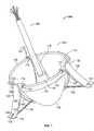
- FIG. 1is a downward perspective of an exemplary valve prosthesis system according to the present disclosure
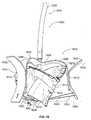
- FIG. 2is a partially-sectional side view of an exemplary valve prosthesis system according to the present disclosure positioned relative to a heart annulus;
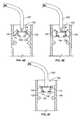
- FIG. 3Ais a side view of an exemplary prosthesis system according to the present disclosure, wherein an exemplary heart valve prosthesis is positioned within an exemplary delivery structure;
- FIG. 3Bis a partially-sectional side view of the exemplary prosthesis system of FIG. 3A , also shown positioned within the exemplary delivery structure;
- FIGS. 4A , 4 B, 4 C, 4 D, 4 E, 4 F, 4 G, 4 H, and 4 Iare schematic views illustrating percutaneous placement of a heart valve prosthesis relative to an annulus according to an exemplary embodiment of the present disclosure
- FIGS. 5 , 6 , and 7are schematic perspective views of variations of a positioning element according to the present disclosure.
- FIGS. 8 , 9 , 10 , 11 and 12are schematic side elevational and perspective views of variations of a prosthetic heart valve in accordance with the present disclosure
- FIGS. 13 and 14are respective side and perspective views of a flexible ring according to the present disclosure.
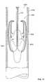
- FIG. 15is a schematic side view of an exemplary valve prosthesis contained within a delivery catheter in accordance with the present disclosure
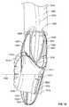
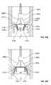
- FIGS. 16 , 17 , 18 , 19 and 20are sequential side views of an exemplary valve prosthesis being outwardly deployed from within a delivery catheter in accordance with the present invention
- FIG. 21is a schematic perspective view of a positioning element according to the present disclosure.
- FIG. 22is a schematic perspective view of a valve prosthesis incorporating the positioning element of FIG. 21 ;
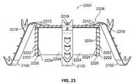
- FIG. 23is a side elevational view of the valve prosthesis of FIG. 22 ;
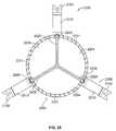
- FIG. 24is a top plan view of the valve prosthesis of FIG. 22 ;
- FIG. 25is a bottom plan view of the valve prosthesis of FIG. 22 ;
- FIGS. 26A , 26 B, 26 C, 26 D, 26 E, 26 F and 26 Gare schematic side views illustrating percutaneous placement of the heart valve prosthesis of FIGS. 22-25 relative to an annulus according to exemplary embodiments of the present disclosure
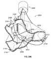
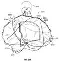
- FIG. 27is a schematic perspective view of a variation of the valve prosthesis of FIG. 22 according to exemplary embodiments of the present disclosure.
- FIGS. 28A , 28 B, 28 C, 28 D, 28 E and 28 Fare schematic perspective views illustrating a system and method of remotely manipulating the positions and orientations various components of the heart valve prosthesis of FIGS. 22-25 in accordance with exemplary embodiments of the present disclosure.
- valve prosthesis systems and deployment systems/methodsare provided according to the present disclosure.
- the disclosed systems and methodspermit surgeons/clinicians to improve heart valve function without invasive surgical intervention.
- the disclosed valve prosthesis systemspermit a heart valve prosthesis to be percutaneously delivered to a desired anatomical location. Once located in the desired anatomical region/locale, the disclosed valve prosthesis system facilitates secure and aligned placement of a heart valve prosthesis relative to a heart annulus.
- Percutaneous delivery of the disclosed heart valve prosthesis as disclosed hereinprovides for efficient and effective clinical placement of a heart valve prosthesis.
- the disclosed heart valve prosthesis and associated delivery techniquesoffer numerous clinical benefits, including enhanced valve function without the need to remove existing valve leaflets, an ability to effectively and efficiently deliver a valve prosthesis percutaneously, and an ability to position a valve prosthesis relative to an annulus to ensure proper orientation relative to anatomical features.
- the valve prosthesis system 100includes a heart valve prosthesis 102 and a delivery structure 104 .
- the valve prosthesis 102includes a flexible ring 106 .
- Mounted with respect to the flexible ring 106are a plurality of leaflet membranes 108 , a valve skirt 110 , and a resilient element 112 .
- the resilient element 112may include a hub 114 and a plurality of legs 116 , each of the legs 116 extending from the hub 114 (e.g., in a regular radial arrangement, as shown in FIG.
- valve prosthesis 102may further include a corresponding plurality of positioning elements 120 , each such positioning element 120 being attached to one of the legs 116 of the resilient element 112 .
- the valve prosthesis 102may include three (3) leaflet membranes 108 , each leaflet membrane 108 assuming an inwardly bowed orientation when mounted with respect to the flexible ring 106 . More or fewer of the leaflet membranes 108 may be employed without departing from the spirit or scope of the present disclosure, provided the desired blood flow functionality is achieved.
- the leaflet membranes 108may be fabricated from xenograft tissue, e.g., the valve leaflets may be fabricated from standard biologic or artificial prosthetic material, such as cryo- or chemically-preserved bovine pericardium or porcine heart valve tissue.
- Synthetic membrane materialsmay also be employed in the fabrication of the leaflet membranes 108 , e.g., fiber-reinforced matrix materials.
- the leaflet membranes 108may be secured with respect to the flexible ring 106 through conventional means, e.g., creation of an annulus and/or cuff that surrounds, in whole or in part, the flexible ring 106 such that each of the plurality of leaflet membranes 108 extends downwardly with respect to the flexible ring 106 .
- the valve skirt 110may extend to a full extent of the flexible ring 106 , e.g., to a fill extent of the circumference of the flexible ring 106 .
- the valve skirt 110may be formed from a single, contiguous structure, or may be defined by a plurality of adjacent and/or overlapping elements that, together, extend along the circumference of flexible ring 106 .
- the valve skirt 110may be sutured with respect to the flexible ring 106 .
- a cuffmay be formed at an edge of the valve skirt 110 , such cuff being adapted to receive the flexible ring 106 therewithin.
- the cuffmay extend along the entire edge of the valve skirt 110 or may be defined at discrete intervals along the length of the valve skirt 110 , such that the valve skirt 110 is mounted with respect to the flexible ring 106 at spaced intervals.
- the valve skirt 110may be fabricated from a variety of substantially flexible and/or pliable materials, e.g., xenographic tissue or a synthetic material that is compatible with blood flow, e.g., a non-thrombogenic material.
- valve skirt 110 and the leaflet membranes 108may be fabricated as integral/contiguous structures, e.g., from a desired xenographic and/or synthetic material, and such integral/continuous structure may be advantageously mounted with respect to the flexible ring 106 such that the functionalities of both elements (i.e., leaflet membrane functionality and valve skirt functionality) are achieved.
- the thickness of the valve skirt 110may be substantially uniform from edge-to-edge or may vary along its length.
- the valve skirt 110would be thicker in a region thereof adjacent the flexible ring 106 and thinner in a region thereof relatively more distant from the flexible ring 106 , thereby enhancing the flexibility of the valve skirt 110 in the latter region to provide more effective sealing functionality relative to adjacent anatomical structures/tissue.
- the thicker region adjacent the flexible ring 106may serve to reduce the likelihood of the valve skirt 110 disengaging from the flexible ring 106 .
- valve skirt 110may extend in a single direction relative to the flexible ring 106 , i.e., downward, it is contemplated according to the present disclosure that the valve skirt 110 may extend both upwardly and downwardly relative to the flexible ring 106 .
- the attachment means for securing the valve skirt 110 relative to the flexible ring 106would not necessarily be located at an edge thereof. Rather, such attachment means, e.g., cuff(s) and/or suturing, may be positioned along an intermediate line/region of the valve skirt 110 .
- a first portion of the valve skirt 110would be free to extend above the flexible ring 106
- a second portion of the valve skirt 110would be free to extend below the flexible ring 106 .
- Both portions of the valve skirt 110i.e., the portions above and below the flexible ring 106 , would advantageously function to seal the valve prosthesis 102 relative to a patient's anatomy when the valve prosthesis 102 is deployed relative thereto, as described in greater detail below.
- a portion of the valve skirt 110 extending above the flexible ring 106may include a notch or discontinuity to accommodate structures associated with the positioning elements 120 , as described in greater detail below.
- the valve skirt 110may have a downward length that is effective to achieve a desired level of sealing relative to surrounding anatomical structures.
- the valve skirt 110may have a downward length of about five (5) millimeters to about fifteen (15) millimeters relative to the flexible ring 106 . Similar dimensions are contemplated for the upward extending portion of the valve skirt 110 in implementations wherein the valve skirt 110 extends both above and below the flexible ring 106 .
- valve skirt 110may be tacked or otherwise secured in at least some manner relative to the resilient element 112 (e.g., to one or more of the legs 116 of the resilient element 112 ). In an alternative embodiment, the valve skirt 110 may be positioned radially outward of the positioning elements 120 .
- the resilient element 112may include three (3) legs 116 mounted in a circumferentially-spaced manner with respect to the flexible ring 106 via the mounting elements 118 .
- Each leg 116may be configured or adapted to include or assume an arcuate shape or bend in the vicinity of the flexible ring 106 .
- the legs 116may be spaced by about 120° relative to each other, although an alternative number and/or spacing of the legs 116 may be employed without departing from the spirit or scope of the present disclosure.
- the mounting elements 118may be of any suitable shape, design, configuration, and/or attachment technique relative to the legs 116 to permit rotational and/or overturning motion of the legs 116 relative to the hub 114 , and/or relative to the flexible ring 106 .
- the mounting elements 118may be substantially C-shaped, and/or tube shaped.
- the mounting elements 118may, for example, be affixed to respective undersides of the legs 116 (e.g., within an arcuate or bent portion thereof) through an appropriate mounting technique, e.g., a tack weld.
- the mounting elements 118may overlay the valve skirt 110 to the extent that the valve skirt 110 is secured to the flexible ring 106 in such circumferential region. Further, the valve skirt 110 may be tacked, adhered or otherwise joined to the underside of one or more of the legs 116 where the same extend over the valve skirt 110 .
- each of the positioning elements 120may be shaped, configured, and/or otherwise adapted to engage tissue, and/or to position the valve prosthesis 102 relative to tissue.
- each positioning element 120may define an outer surface 122 , an inner surface 124 opposite the outer surface 122 , an upper arcuate region 126 , and a lower arcuate region 128 opposite the upper arcuate region 126 .
- Each of the positioning elements 120may be coupled (e.g., fixedly joined) to a corresponding leg 116 of the resilient element 112 , e.g., through a weld between the inner surface 124 of the positioning element 120 a corresponding outer surface of the leg 116 .
- the positioning elements 120may be dimensioned such that the upper arcuate regions 126 thereof extend above the flexible ring 106 (e.g., when the valve prosthesis 102 assumes the orientation depicted in FIG. 1 ).
- the upper and lower arcuate regions 126 , 128 of the positioning elements 120may be spaced by a distance that facilitates positioning of the valve prosthesis 102 relative to a heart annulus, as described in greater detail below.
- the upper and lower arcuate regions 126 , 128may be spaced by between about seven (7) millimeters and about twenty-five (25) millimeters.
- the positioning elements 120 and the legs 116may be fabricated from a material that permits at least some degree of flexibility/deformation (e.g., elastic deformation), such as stainless steel or Nitinol of an appropriate thickness/gauge. Other materials for the positioning elements 120 and/or the legs 116 are possible.
- the lower arcuate regions 128 of the positioning elements 120may include a pair of spaced apertures 130 , 132 .
- the delivery structure 104may include a plurality of filaments or cords 134 , each cord 134 being threaded through a positioning element 120 via the pair of spaced apertures 130 , 132 formed therein, such that separate lengths 136 of the cord 134 extend away from the apertures 130 , 132 and radially inwardly toward the hub 114 of the resilient element 112 . As may be more clearly seen in FIG.
- the hub 114 of the resilient element 112may include one or more lumen(s) 200 (e.g., a centrally-located lumen 200 ), the delivery structure 104 may include a delivery tube 202 having one or more corresponding lumens 204 (e.g., an axially located lumen), and the lengths 136 of the cords 134 may pass from the respective lower arcuate regions 128 of the positioning elements 120 toward the hub 114 , into and through the lumen 200 thereof, and into and through the lumen 204 of the delivery tube 202 .
- lumen(s) 200e.g., a centrally-located lumen 200
- the delivery structure 104may include a delivery tube 202 having one or more corresponding lumens 204 (e.g., an axially located lumen)
- the lengths 136 of the cords 134may pass from the respective lower arcuate regions 128 of the positioning elements 120 toward the hub 114 , into and through the lumen 200 thereof, and into and through the
- Such lengths 136 of the cords 134may facilitate deployment of the valve prosthesis 102 relative to an annulus and/or associated heart tissue.
- the delivery tube 202may be flexible, and the lumen or lumens 204 may accommodate passage of a plurality of lengths 136 of cords 134 .
- three (3) positioning elements 120are associated with the valve prosthesis 102 and each positioning element 120 interacts with a separate cord 134 .
- the respective lumen(s) 200 , 204 of the hub 114 and the delivery tube 200may be appropriately sized and/or of an appropriate number to accommodate least six (6) separate lengths 136 of cords 134 , based on the looping of each cord 134 through a pair of spaced apertures 130 , 132 formed at or near the respective lower arcuate regions 128 of the positioning elements 120 .
- the legs 116 of the resilient element 112may cooperate with the hub 114 thereof and/or with the flexible ring 106 to provide stability to the valve prosthesis 102 , e.g., during the deployment process, and/or during the useful life of the valve prosthesis 102 in situ.
- the structural interaction between the legs 116 and the flexible ring 106 , and/or between the legs 116 and the hub 114permits a surgeon/clinician to utilize the lengths 136 of the cords 134 and the delivery structure 104 to remotely operate the valve prosthesis 102 (e.g., to remotely move/rotate the legs 116 relative to the flexible ring 106 and/or relative to the hub 114 ).
- Each of the legs 116may, for example, include one or more joints along its respective length (e.g., one or more living hinges at or near a mid-point thereof) to facilitate collapse of valve prosthesis 102 for catheter-based delivery thereof.
- one or more such jointsmay store energy so as to facilitate the delivery of a spring force to expand the flexible ring 106 to a full diameter thereof (or at least a substantial fraction thereof), or assist in an otherwise substantially self-powered expansion thereof, upon deployment of the valve prosthesis 102 in situ.
- one or more such jointsmay further store energy so as to urge the positioning elements 120 radially outward (e.g., toward secure engagement with corresponding tissue, and/or radially outward from a compressed shape associated with intra-catheter delivery).
- three (3) legs 116may extend from the hub 114 , such that the resilient element 112 assumes a ‘tripod’-type shape for expanding and/or supporting the valve prosthesis 102 (e.g., helping the flexible ring 106 to assume and/or maintain a shape consistent with the intended function of the valve prosthesis 102 , and/or to urge the positioning elements 120 radially outward) during deployment and/or while implanted in situ.
- valve prosthesis 102 of the valve prosthesis system 100is depicted in alignment and engagement with an heart valve annulus “A” and a heart wall “W” of a patient.
- the valve prosthesis 102is further shown displacing heart valve leaflet structure “V” (e.g., the valve prosthesis 102 is implanted within the annulus A for purposes of providing the valve function for which the valve leaflet structure V is no longer well suited).
- the annulus Ais depicted in an enlarged and symmetric fashion for ease of description.
- the actual geometric and dimensional details of the relevant anatomical structuresare well known to persons skilled in the art. As shown in FIG.
- each of the upper arcuate regions 126 of the respective positioning elements 120may be positioned advantageously so as to engage a corresponding part of an upper portion of the annulus A. In this fashion, at least, the positioning elements 120 may be employed in cooperation with each other to align the valve prosthesis 102 relative to the annulus A. As also shown in FIG. 2 , each of the lower arcuate regions 128 may be positioned advantageously so as to engage a corresponding part of the wall W below the annulus A. In this fashion, at least, the positioning elements 120 may be employed in cooperation with each other to stabilize and secure the valve prosthesis 102 relative to the overall anatomical environment.
- valve prosthesis 102may deflect the lower arcuate regions 128 of the positioning elements 120 inward by pulling or otherwise manipulating or moving the respective lengths 136 of the cords 134 a sufficient extent radially inwardly and/or upwardly through the hub 114 and the delivery tube 202 to cause the lower arcuate regions 128 of the positioning elements 120 to disengage from the wall W.
- the surgeon/clinicianmay then reposition the structure of the valve prosthesis 102 relative to the overall anatomical environment by pulling, pushing, or otherwise manipulating or moving the delivery tube 202 to a desired extent with respect to the delivery catheter (not separately shown). Such manipulation may, for example, be translated to the valve prosthesis 102 via the hub 114 and the legs 116 of the resilient element 112 .
- Such manipulationmay, for example, be translated to the valve prosthesis 102 via the hub 114 and the legs 116 of the resilient element 112 .
- the surgeon/clinicianmay elect to pull the valve prosthesis 102 at least partially back upward, causing the lower arcuate regions 128 of the positioning elements to engage a corresponding part of a lower portion of the annulus A, and/or to engage the heart valve leaflet structure V, which in at least some instances results in the valve prosthesis 102 to be lodged and/or anchored in a particularly secure fashion within the annulus A.
- the surgeon/clinicianmay withdraw the cords 134 from the valve prosthesis 102 through the delivery tube 202 by pulling outward on one length 136 thereof to a sufficient extent while leaving the other length 136 loose.
- the surgeon/clinicianmay further withdraw the remainder of the delivery structure 104 from the valve prosthesis 102 by separating the delivery tube 202 from the hub 114 of the resilient element 112 .
- Means for disconnecting the delivery tube 202 from the hub 114may take a variety of forms, e.g., a screw thread arrangement at the end of the delivery tube 202 that may be disengaged from a corresponding socket associated with the hub 114 .
- connection and/or disconnection meansare possible, including bayonet lock mechanisms, detent engagement mechanisms, and the like, at least some of which are further described hereinbelow.
- Tissue-engaging featurese.g., barbs, tacks or the like, may be formed on, in, and/or through one or more tissue-engaging surfaces of the respective positioning elements 120 .
- tissue-engaging featuresmay be formed on the outer surface 122 of the positioning elements 120 , e.g., within the upper and/or lower arcuate regions 126 , 128 .
- surface treatments and/or adjunct structuresmay be associated with the positioning elements 120 to promote tissue in-growth, thereby further enhancing the stability/security of an implanted valve prosthesis according to the present disclosure.
- a biologic coating and/or a material or fabric that promotes tissue in-growthe.g., DACRONTM material, may be applied to a desired portion/region of the respective outer surfaces 122 of the positioning elements 120 .
- valve prostheses and valve prosthesis systems and methodshave applicability in a variety of anatomical regions, e.g., as a prosthesis for the mitral valve, aortic valve, pulmonary valve, or tricuspid valve.
- Embodiments of the disclosed valve prosthesishave particular applicability for mitral valve applications.
- the valve prosthesis system 100 and/or the valve prosthesis 102may be sized and dimensioned to accommodate such use by adapting the annular ring to fit in the requisite anatomical space, e.g., a mitral, aortic, pulmonary, or tricuspid valve opening of the heart.
- the heart valve prosthesis 102may assume a collapsed configuration within a lumen 300 of a catheter 302 .
- the positioning elements 120may be substantially inverted, e.g., rotated approximately 180° relative to the flexible ring 106 to which they are mounted and relative to the hub 114 of the resilient element 112 , as compared to the relative positions or orientations the positioning elements 120 may tend to occupy with respect to such structure (e.g., as shown in FIG. 1 ) when not being subjected to the application of opposing outside forces.
- the flexible ring 106may also be substantially deformed and the legs 116 of the resilient element 112 may be deflected so as to permit the valve prosthesis 102 to fit within the catheter 302 .
- the upper and lower arcuate regions 126 , 128 associated with the respective positioning elements 120may be inwardly directed toward the delivery tube 202 .
- the upper and lower arcuate portions 126 , 128 of the respective positioning elements 120may be associated with and/or terminate in respective tips 304 , 306 , and such tips 304 , 306 may feature cut-outs (not shown in FIGS.
- FIGS. 4A-4Ian exemplary sequence of steps for percutaneously delivering and positioning the disclosed valve prosthesis 102 in a desired anatomical location are schematically depicted.
- the valve prosthesis 102may be navigated to the desired anatomical location, e.g., adjacent a mitral valve, aortic valve, pulmonary valve, or tricuspid valve, within a delivery catheter 400 having a distal end 402 .
- the valve prosthesis 102may be delivered to the mitral valve cavity transseptally or by direct venous or arterial delivery to the aortic valve, pulmonary valve, or tricuspid valve cavities.
- the valve prosthesismay be navigated to a desired location using a guide wire (not shown) that cooperates with a corresponding guide wire lumen (not shown) formed in or otherwise present within the delivery catheter 400 .
- the valve prosthesis 102may be advanced through the delivery catheter 400 along an associated guide wire in a collapsed/inverted orientation (by being pushed, for example, by the delivery tube 202 ) to the implantation position (e.g., left atrium for mitral valve) where the valve prosthesis 102 is deployed adjacent the diseased valve for subsequent implantation therein.
- valve prosthesis 102may be pre-positioned within the delivery catheter 400 at or near the distal end 402 , and both the valve prosthesis 102 and the distal end 402 of the delivery catheter 400 may be so advanced in unison along an associated guide wire.
- the delivery tube 202may be extended relative to the delivery catheter 400 to push the valve prosthesis 102 outward of the catheter via a corresponding opening in the distal end 402 .
- resilient properties of several components of the valve prosthesis 102particularly the flexible ring 106 and the legs 116 of the resilient element 112 ( FIG. 2 ), may cause at least the flexible ring 106 to automatically resume its non-deformed/uncompressed shape (e.g., as seen in FIG. 4B as well as all later figures in the sequence of FIGS.
- valve prosthesis 102may tend eventually to fully relax, and assume a generally non-deformed orientation, wherein the positioning elements 120 are seen to have overturned or become inverted by rotating both outwardly and downwardly past the horizontal (e.g., so that the outer surfaces 122 thereof face generally outward again, and the upper and lower arcuate regions 126 , 128 thereof are, once again, outwardly directed).
- the valve skirt 110may be appropriately substantially downwardly oriented and positioned for performing an advantageous sealing function (e.g., as against valve prolapse) upon being positioned in a desired anatomical position.
- the surgeon/clinicianmay deflect the lower arcuate regions 128 of the positioning elements 120 inward by pulling the respective lengths 136 of the cords 134 ( FIG. 2 ) a sufficient extent radially inward toward, and/or upward through, the hub 114 ( FIG. 2 ) and the delivery tube 202 in such a way as to continue (see FIG. 4D ) an overturning or inverting motion of the positioning elements 120 relative to the flexible ring 106 and the hub 114 ( FIG. 2 ), progressing through sequential orientations as depicted in FIGS. 4D and 4E and arriving at the particularly notable orientation depicted in FIG.
- the surgeon/clinicianmay be permitted to accomplish such deflection of the positioning elements 120 by grasping or otherwise seizing respective proximal ends (not shown) of the lengths 136 of the plurality of cords 134 ( FIG. 2 ) disposed outside the delivery catheter 400 and outside the patient's body and pulling such ends outward of the delivery catheter 400 and the patient's body.
- Such withdrawal of the lengths 136 of the cords 134results in the lower arcuate regions 128 of the positioning elements 120 being pulled radially inwardly, e.g., to a point where the tips 306 of the lower arcuate regions 128 extend at least partially downwardly toward the diseased valve.
- FIG. 1As shown in FIG.
- such downwardly-directed and relatively more closely spaced lower arcuate regions 128may be utilized in the manner of a probe or ‘plow’ to deflect the patient's leaflet membranes (see, e.g., valve structure V in FIG. 2 ) and/or otherwise facilitate advancing the valve prosthesis 102 downward into the patient's diseased valve such that the valve prosthesis 102 is able to be positioned at an appropriate implantation elevation and an appropriate lateral position relative to the annulus A,
- the upper arcuate regions 126 of the respective positioning elements 120may be cooperatively adapted to be contained within a common plane, e.g., in the manner of a “top hat”, so as to facilitate positioning/alignment of the valve prosthesis 102 relative to the annulus A.
- the circumferentially interrupted aspect exhibited by of the valve prosthesis 102 and collectively defined by the positioning elements 120may facilitate both inversion of the positioning elements 120 during percutaneous introduction, and effective alignment and tissue engagement/stability upon final implantation and in situ valve function.
- the valve prosthesis 102may be generally aligned in a desirable fashion upon each of the plurality of upper arcuate regions 126 substantially engaging a corresponding part of the upper portion of the annulus A.
- the valve prosthesis 102may now be further positioned and/or spatially oriented relative to the annulus A in the manner desired by the surgeon/clinician, e.g., as viewed through conventional imaging instrumentation.
- the positioning elements 120and particularly, the upper arcuate regions 126 thereof
- the surgeon/clinicianmay begin to relax an accumulated degree of tension within the lengths 136 of the plurality of cords 134 ( FIG. 2 ), and thereby begin to allow a corresponding accumulation of energy/spring force contained in the legs 116 ( FIG. 2 ) of the resilient element 112 ( FIG.
- the lower arcuate regions 128may be allowed to rotate radially outward to an extent sufficient to permit the respective tips 306 thereof to contact and/or engage the cardiac tissue comprising the wall W. Having retracted to an extent sufficient to permit such tissue engagement, the legs 116 of the resilient element 112 and/or the positioning elements 120 may still retain sufficient energy/spring force to further cause the respective tips 306 to collectively press against and/or become substantially embedded in place with respect to the wall W.
- Such collective spring forcemay be sufficient to permit the lower arcuate regions 128 of the positioning elements 120 to offer a degree of resistance against vertically upward pullout or displacement of the valve prosthesis 102 , e.g., a degree of resistance at least comparable to a naturally strong degree of resistance against vertically downward displacement thereof offered by the upper arcuate elements 126 positioned across and/or against the annulus A.
- the cords 134may be withdrawn from the positioning elements 120 . Thereafter, the remainder of the delivery structure 104 may be disconnected and/or separated from the valve prosthesis 102 (e.g., the delivery tube 202 may be disconnected from the hub 114 ( FIG. 2 ), thereby leaving the valve prosthesis 102 in an appropriate position relative to the patient's diseased heart valve to serve as a functional replacement thereof.
- the positioning elements 120may serve to maintain the native leaflet membranes (see valve structure V in FIG. 2 ) in an open position, and each of the leaflet membranes 108 and the valve skirt 110 mounted with respect to the flexible ring 106 may function to ensure appropriate directional control of blood flow therethrough.
- the disclosed valve prosthesis and associated delivery structures/methodsoffer numerous advantages relative to existing systems.
- the positioning elements associated with the disclosed valve prosthesis valveinclude upper and lower arcuate regions that may advantageously function to engage the annulus as well as the wall of the ventricular chamber below the annulus, thereby securely aligning and stabilizing the valve prosthesis (e.g., in a redeployable manner) relative thereto.
- the invertible and collapsible aspects of the valve prosthesismay facilitate efficient percutaneous delivery and in situ manipulation of the disclosed valve prosthesis system.
- the disclosed valve skirtmay enhance sealing functionality of the disclosed valve prosthesis when positioned in situ as compared to that which might otherwise be the case (e.g., without such a skirt and/or the annular sealing function provided thereby).
- the “top-hat” geometry and/or functionality of the upper arcuate regions of the positioning elementsmay advantageously function to accurately and securely position the valve prosthesis relative to an annulus and associated anatomical structures.
- the disclosed design and implantation methodologymay not require extensive surgery, and that the disclosed positioning elements may function to provide stable and well aligned implantation, central blood flow, and/or a stable platform for the leaflet membranes. Moreover, positioning may be more precise than with a balloon expandable device, such as a stent. Additionally, and also unlike a stent, the positioning may potentially be repeated (e.g., until the desired implantation position and/or orientation is achieved).
- the heart valve prosthesis described hereinmay also allow anchoring relative to the valve annulus in states of the diseased valve in which a stent may not encounter sufficient tissue to which to adhere (e.g., as is commonly the case with respect to mitral valve disease).
- the heart valve prosthesismay be placed squarely at the site of a diseased heart valve, as distinct from certain existing heart valve prosthesis implementations characterized by the use of stents configured for placement in the connecting blood vessels adjacent to and/or near the diseased heart valve, and, as such, are designed to be disposed in spaced relation therewith, whether during or after implantation, or during in situ operation.
- stentsconfigured for placement in the connecting blood vessels adjacent to and/or near the diseased heart valve, and, as such, are designed to be disposed in spaced relation therewith, whether during or after implantation, or during in situ operation.
- the positioning elements 120 of the present disclosuremay be implemented by one or more of a plurality of variations, including those depicted in FIGS. 5-7 . More particularly, a positioning element 500 depicted in FIG. 5 is one such variation of the positioning element 120 .
- the positioning element 500may include upper and lower arcuate regions 502 , 504 , an intermediate region 506 disposed therebetween, and an outer surface 508 .
- An array 510 of holes 512may be formed in the outer surface 508 in a vicinity of the intermediate region 506 to encourage in-growth of tissue, increasing positional and orientational stability in situ.
- a positioning element 600is another such variation of the positioning element 120 .
- the positioning element 600may include upper and lower arcuate regions 602 , 604 , an intermediate region 606 disposed therebetween, and an outer surface 608 .
- An array 610 of spikes or spurs 612may be provided, extending from the outer surface 608 in a vicinity of the intermediate region 606 to facilitate secure engagement of tissue, similarly increasing positional and orientational stability in situ.
- a positioning element 700 depicted in FIG. 7is yet another variation of the positioning element 120 .
- the positioning element 700may include upper and lower arcuate regions 702 , 704 , an intermediate region 706 disposed therebetween, and an outer surface 708 .
- An array 710 of holes 712may be formed in, and spikes or spurs 714 may be provided so as to extend from, the outer surface 708 in a vicinity of the intermediate region 706 to facilitate both in-growth of tissue and secure engagement of tissue, also increasing positional and orientational stability in situ. While the holes 512 and 712 and the spurs 612 and 714 are shown in FIGS. 5-7 as appearing in the respective intermediate regions 506 , 606 , 706 of the respective positioning elements 500 , 600 , 700 , such features may alternatively, and/or in addition, be positioned in one or both of the upper 502 , 602 , 702 and lower 504 , 604 , 704 arcuate regions thereof.
- a leg 802 of a resilient element 804may support the positioning element 800 , which may in turn include a lower arcuate region 806 having a tissue-engaging tip 808 that, in a retracted state of the lower arcuate region 806 , may be coiled or ‘rolled up’ so as to extend inward toward an intermediate region 810 of the positioning element and/or downward toward itself.
- a deployment structure 812may include a cord 814 attached to the lower arcuate region 806 (e.g., near the tip 808 thereof) to uncoil the lower arcuate region 806 so as to permit the tip 808 to be redirected outward so as to be capable of engaging with a the cardiac tissue comprising a patient's heart wall (not shown).
- a surgeon/clinicianmay be permitted to pull outward on the cord 814 during positioning of the positioning element 800 , and once the tip 808 has begun to engage the cardiac tissue, to release the cord 814 , allowing an accumulated energy/spring force inherent in the lower arcuate region 806 (e.g., the same having a coil-spring configuration) to impinge with additional force upon the cardiac tissue.
- positioning element 800may be provided in a valve prosthesis 816 (not otherwise shown) such that at least some balancing of reaction forces can be achieved, and an upper arcuate region 818 of the positioning element 800 may have a similar coiled configuration (not separately shown) to that of the lower arcuate region 806 .
- the valve prosthesis 900may include a resilient element 902 having a leg 904 generally similar to the legs 116 associated with the above-described resilient element 112 .
- the leg 904may support a claw 906 having an upper jaw 908 , a lower jaw 910 , and a hinge 912 disposed between the upper and lower jaws 908 , 910 .
- the valve prosthesis 900may further include a torsional spring (not shown) for biasing the upper and lower jaws 908 , 910 of the claw 906 in favor of closure toward each other, and securely engaging the cardiac tissue of a patient's heart wall.
- a deployment structure 914may include a cord 916 attached to the upper and lower jaws 908 , 910 .
- a surgeon/clinicianmay be permitted to pull outward on the cord 916 to hold the claw 906 open during positioning of the claw 906 .
- the surgeon/clinicianmay be permitted to release the cord 916 , allowing the spring bias to act on the upper and lower jaws 908 , 910 and thereby allowing the claw 906 to affix itself to the cardiac tissue.
- Multiple instances (not shown) of the claw 906may be provided in the valve prosthesis 900 .
- valve prostheses 1000 , 1100 , and 1200shown partially and schematically in FIGS. 10 , 11 and 12 , respectively.
- the valve prosthesis 1000 of FIG. 10may include a resilient element 1002 having multiple instances of a leg 1004 extending from a hub 1006 .
- the leg 1004may itself be a spring, and may include at least two leaves 1008 joined at an arcuate or bend region 1010 .
- the valve prosthesis 1000may further include one or more engaging elements 1012 , each of which may include a plurality of prongs 1014 for piercing and/or otherwise invasively engaging cardiac tissue as appropriate to secure the valve prosthesis 1000 in place relative to a diseased heart valve, and/or relative to an annulus associated therewith.
- the engaging element 1012may be supported by one of the leaves 1008 of the leg 1004 , and the valve prosthesis 1000 may include a plurality of sets of two engaging elements 1012 (e.g., having two prongs 1014 each) as shown in FIG. 10 .
- the valve prosthesis 1100 of FIG. 11may include a resilient element 1102 having multiple instances of a leg 1104 extending from a hub 1106 .
- the leg 1104may itself be a spring, and may include at least two leaves 1108 joined at an arcuate or bend region 1110 .
- the valve prosthesis 1100may further include one or more engaging elements 1112 , each of which may include two arms 1114 extending outward from a common point of connection in a V shape.
- the valve prosthesis 1100may further include biasing springs (indicated schematically at reference numeral 1116 ) for urging the arms 1114 of the engaging elements 1112 together for purposes of closing the engaging element 1112 about an annulus associated with a patient's diseased heart valve.
- the engaging element 1112may be supported by one of the leaves 1108 of the leg 1104 , and the valve prosthesis 1100 may include a plurality of such engaging elements 1112 .
- the valve prosthesis 1200 of FIG. 12may include a resilient element 1202 having multiple instances of a leg 1204 extending from a hub 1206 .
- the leg 1204may itself be a spring, and includes at least two leaves 1208 joined at an arcuate or bend region 1210 .
- the valve prosthesis 1200may further include one or more engaging elements 1212 , each of which may include a plurality of teeth 1214 for engaging cardiac tissue as appropriate to secure the valve prosthesis 1200 relative to a diseased heart valve.
- the engaging element 1212may be directly affixed to one of the leaves 1208 of the leg 1204 (e.g., the valve prosthesis 1200 may include a plurality of engaging elements 1212 having two rows of teeth 1214 each as shown in FIG. 12 ).
- the engaging element 1212may be hinged at a central location between the two rows of teeth 1214 such that the engaging element 1212 may be movable to at least some degree relative to the leg 1204 . Accordingly, in at least some such embodiments, the engaging element 1212 may be utilized in the manner of a toothed claw otherwise structurally and functionally similar to the claw 906 described above with reference to FIG. 9 .
- a variation of the above-discussed flexible ring 106is embodied by a flexible ring 1300 illustrated in FIGS. 13 and 14 .
- the flexible ring 1300may be resilient such that it may tend (e.g., absent any substantial compressive forces) to expand outward to assume a three-dimensional shape (e.g., the three-dimensional shape shown FIG. 14 ), in which the flexible ring 1300 may have a not insubstantial vertical height, in addition to a characteristic lateral width or diameter. More particularly, the flexible ring 1300 may include multiple instances of a hoop segment 1302 .
- the hoop segments 1302may be contained within a common horizontal plane (e.g., upon the flexible ring 1300 being expanded out to its maximum width and height) wherein the hoop segments may be separated by and/or coupled via a corresponding number of instances of a coupling segment 1304 extending vertically relative to the common horizontal plane, constituting at least a portion of the height extent of the flexible ring 1300 .
- Each hoop segment 1302may further include a notch 1306 to facilitate secure coupling of one or more of a valve skirt similar to the above-described valve skirt 110 , at least one leaflet membrane similar to the above-described leaflet membranes 108 , and/or an associated annulus or cuff similar to that described above.
- such couplingmay be obtained via a knotted suture (not shown) at least partially lodged within the notch 1306 so as to restrict relative movement of the valve skirt, leaflet membrane, and/or cuff relative to and/or about a circumference of the flexible ring 1300 .
- Each of the coupling segments 1304may comprise a spring having two leaves 1308 joined at an arcuate or bend region 1310 , whereby the flexible ring 1300 may be particularly amenable to being radially compressed and/or to assume a compact shape suitable for compressing a corresponding valve prosthesis (not separately shown) of which the flexible ring 1300 is a part, and/or passing such a prosthesis through a narrow-gauge catheter (not shown).
- the flexible ring 1300may include intermittent breaks in its circumference in the plane of the hoop segments 1302 (e.g., associated with the coupling segments 1304 ), its geometry may further contribute to an elastic radial compressibility exhibited by the flexible ring 1300 .
- the bend regions 1310 of the coupling segments 1304may further serve as anchoring points functionally similar to the notches 1306 .
- such notches 1306may be used as anchoring points for securing, and/or limiting a length extent of, commisure seams (not shown in FIGS. 13-14 ; see, e.g., corresponding structure illustrated and described below with reference to FIGS. 16-20 ) formed between corresponding leaflet membranes (not shown) of a heart valve prosthesis (not shown) incorporating the flexible ring 1300 in accordance with embodiments of the present disclosure.
- valve prosthesis 1500illustrated in FIG. 15 .
- the resilient element 1502 of the valve prosthesis 1500may be structurally and functionally similar to the above-described resilient element 112 .
- the legs 1504 of the resilient element 1502may flex inwardly toward the delivery tube 202 .
- the legs 1504may be adapted to flex inwardly toward the delivery tube 202 in a manner that facilitates an enhanced degree of radial compression of the valve prosthesis 1500 .
- Such flexure of the legs 1504may further permit the valve prosthesis 1500 to pass along a lumen 1506 of a catheter 1508 exhibiting a smaller internal diameter than would otherwise be the case.
- a modified version of the valve prosthesis system 100 in accordance with the present disclosureis embodied by a valve prosthesis system 1600 illustrated in various stages of operation in FIGS. 16 , 17 , 18 , 19 , and 20 .
- the valve prosthesis system 1600may include a valve prosthesis 1602 that is a modified version of the valve prosthesis 102 including substantially all structural and functional features thereof, with at least some exceptions as discussed below.
- the valve prosthesis 1602may include a resilient element 1604 having multiple instances of a leg 1606 extending radially outward from a hub 1608 , and multiple instances of a leaflet membrane 1610 .
- Commissures 1612 between the leaflet membranes 1610may be partially closed, or at least limited in length via respective sutured seams 1614 formed between the leaflet membranes 1610 .
- the sutured seams 1614may extend from a flexible ring 1616 of the valve prosthesis 1602 , or from a location in spaced relation below the flexible ring 1616 (e.g., as in embodiments of the valve prosthesis (not specifically shown) in which each of the leaflet membranes 1610 forms a portion of a larger membrane structure of unitary construction), downward to a point coinciding with respective free ends or distal edges of the leaflet membranes 1610 .
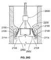
- the valve prosthesis system 1600may further include a delivery structure 1618 that, in addition to having cables 1620 and a delivery tube 1622 structurally and functionally similar to corresponding aspects of the delivery structure 104 , further includes a tower 1624 extending downward from the hub 1608 .
- the tower 1624may at least participate in defining a central axis 1625 of the valve prosthesis system 1600 , and may further introduce an axial (e.g., vertical or lengthwise) separation between an elevation (e.g., generally indicated at 1626 in FIG. 20 ) at which the legs 1606 meet the hub 1608 and an elevation (e.g., generally indicated at 1628 in FIG. 20 ) at which the cables 1620 extend, and/or are deployed, outward from the central axis 1625 .
- an elevatione.g., generally indicated at 1626 in FIG. 20
- an elevatione.g., generally indicated at 1628 in FIG. 20
- such an arrangementmay have the advantage of displacing and/or routing the cables 1620 generally away from an elevation (e.g., generally shown at 1630 in FIG.
- such an arrangementmay advantageously reduce and/or eliminate a risk of the cables 1620 abrading or cutting the leaflet membranes 1610 and/or the sutures of the sutured scams 1614 during a process of deploying, adjusting a position of, and/or otherwise implanting the valve prosthesis 1602 .
- a riskdoes not necessarily exist with respect to any particular embodiment of a heart valve prosthesis in accordance with the present embodiment.
- the use of a tower 1624 , or of another component structurally and/or functionally similar thereto, to introduce an appropriate axial separation between the cables 1620 and the leaflet membranes 1610 , and/or between the cables 1620 and the sutured seams 1614may provide a particular advantage.
- such an arrangementmay further permit additional energy and/or spring force to be built up within the resilient element 1604 by imparting significant flexure to the resilient element 1604 where the legs 1608 meet the hub 1606 .
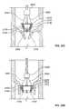
- a sufficient amount of flexuremay be imparted thereby to the resilient element 1604 to cause the hub 1606 to be raised to an elevation substantially entirely above those of the respective positioning elements 1632 during a corresponding process of deployment from a catheter 1634 , in which the positioning elements 1632 may be overturned or inverted relative to the flexible ring 1616 and the hub 1608 in preparation for placement of the valve prosthesis 1602 with respect to a patient's diseased heart valve.
- Such elevated placement of the hub 1608 relative to the positioning elements 1632may further persist in the final in situ configuration of the valve prosthesis 1602 within the diseased heart valve (not specifically shown), such that an elevation of the hub 1608 may be and/or remain even with or above that of the corresponding annulus A (see FIG. 2 for comparison).
- the legs 1608may assume a final configuration relative to the hub 1606 such that: i) the legs 1608 either effectively no longer extend vertically upward from the hub 1608 ; or ii) an extent to which the legs 1608 continues to so extend upward from the hub 1606 is substantially reduced; and/or iii), the legs 1608 have substantially completely been overturned relative to the flexible ring 1616 so as to extend substantially completely downwardly from the hub 1608 . Any one or all of these arrangements of the legs 1608 of the resilient element 1604 relative to the hub 1606 thereof and/or relative to the flexible ring 1616 may have the advantageous effect of reducing an occurrence of or an extent of eddies or turbulence in the flow of blood past or through the resilient element 1604 .
- an extent and/or magnitude of a shear force characteristic of the flow of blood through the heart valve prosthesis 1602may be beneficially adjusted, limited, and/or reduced.
- a modified version of the positioning element 120is embodied by the positioning element 2100 of FIG. 21 .
- the positioning element 2100may be fabricated from a metallic material.
- the positioning element 2100may be fabricated from a shape memory alloy (SMA, also known as a smart alloy, memory metal, or muscle wire) such as the nickel-titanium alloy Nitinol.
- SMAshape memory alloy
- the positioning element 2100may include proximal and distal end regions 2102 , 2104 , and an intermediate region 2106 disposed between the proximal and distal end regions 2102 , 2104 .
- the intermediate and distal end regions 2106 , 2104 of the positioning element 2100may collectively define a hook 2108 for invasively hooking and/or otherwise engaging cardiac tissue, such as leaflet tissue associated with a diseased heart valve (not separately shown), thereby at least partially anchoring the positioning element 2100 with respect to such valve.
- the hook 2108may include a shank portion 2110 at least partially defined by the intermediate region 2106 of the positioning element 2100 , and a bend portion 2112 and a barb portion 2114 defined by the distal end region 2104 thereof.
- a free end 2116 of the barb portion 2114may be sufficiently sharp and/or pointed to permit the barb portion 2114 to pierce the tissue of a heart valve leaflet.
- the barb portion 2114 and the free end 2116 thereofmay be sized, shaped, oriented, and/or configured to extend upward from the left ventricular side at least partially against the direction of blood flow through the native heart valve, and to permit the barb portion 2114 to pierce, connect with, and/or anchor with one or more of the heart valve leaflets.
- the barb portion 2114 of the hook 2108may take any suitable shape, including but not limited to the shape illustrated in FIG. 21 , including wherein the barb portion 2114 is provided in the form of an upturned fork including a pair of tines 2118 , each of which terminates in a point 2120 .
- each of the points 2120 of the tines 2118is positionable against the tissue of a heart valve leaflet, and is of sufficient sharpness such that a moderate amount of upwardly directed force applied to the barb portion 2114 (e.g., from the shank portion 2110 and/or via the bend portion 2112 , such as in the event of an upward pull by the surgeon on the positioning element 2100 during the implantation of a prosthesis of which the positioning element 2100 forms a part) can cause the tines 2118 to pierce the heart valve leaflet, and to plunge into the tissue thereof.
- a moderate amount of upwardly directed force applied to the barb portion 2114e.g., from the shank portion 2110 and/or via the bend portion 2112 , such as in the event of an upward pull by the surgeon on the positioning element 2100 during the implantation of a prosthesis of which the positioning element 2100 forms a part
- the barb portion 2114 of the hook 2108may further define a web region 2122 disposed between the tines 2118 and defining a curved surface 2124 .
- the curved surface 2124may be defined by a relatively large radius as compared to those which define the points 2120 of the tines 2118 .
- the points 2120may define a height dimension 2126 of the tines 2118 relative to a lowermost point 2128 on the web surface 2124 .
- the tines 2118 of the barb portion 2114may be permitted to plunge into the tissue of a heart valve leaflet at least to a depth substantially equivalent to the height dimension 2126 .
- the radius associated with the web surface 2124may be large enough, and/or the edges of the web surface 2124 may be sufficiently dull or otherwise rounded, to prevent further tearing or cutting into the tissue of a heart valve leaflet.
- the web surface 2124may be of an appropriate size, shape and/or configuration to establish, in the form of the height dimension 2126 , a practical limit in terms of a depth to which the tines 2118 will be allowed to plunge into the tissue of a heart valve upon exposure to ordinary manipulation and urging forces associated with heart valve prosthesis implantation.
- barb portion 2114 of the hook 2108is shown in FIG. 21 and described above to include wherein the barb portion 2114 is provided in the form of an upturned fork including a pair of tines 2118 , each of which terminates in a point 2120 , other configurations for the barb portion 2114 are possible.
- such other configurationmay include, but not necessarily be limited to: upturned forks for the barb portion including more than two tines; an upturned, non-forked, tissue-piercing element/spear/barb for the barb portion and provided with an alternatively-configured feature for limiting tissue piercing depth (e.g, in the form of a surrounding ‘hilt’ or an appropriate flange or other surface); an upturned, non-forked, tissue-piercing element/spear/barb for the barb portion and provided without a separate feature for limiting tissue piercing depth, etc.).
- upturned forks for the barb portionincluding more than two tines
- an upturned, non-forked, tissue-piercing element/spear/barbfor the barb portion and provided with an alternatively-configured feature for limiting tissue piercing depth (e.g, in the form of a surrounding ‘hilt’ or an appropriate flange or other surface)
- the proximal end region 2102 of the positioning element 2100may define a hook 2130 for invasively hooking and/or otherwise engaging cardiac tissue, such as annulus tissue associated with a diseased heart valve (not separately shown), thereby at least partially anchoring the positioning element 2100 with respect to such valve.
- the hook 2130may include a bend portion 2132 and a barb portion 2134 defined by the proximal end region 2102 of the positioning element 2100 .
- a free end 2136 of the barb portion 2134may be sufficiently sharp and/or pointed to permit the barb portion 2134 to pierce the tissue of a heart valve annulus
- the barb portion 2134 and the free end 2126 thereofmay be sized, shaped, oriented, and/or configured to extend upward at least partially against the direction of blood flow through the native heart valve, and to permit the barb portion 2134 to pierce, connect with, and/or anchor with the heart valve annulus from the left ventricular side (e.g., from below a plane of the heart valve annulus).
- the barb portion 2134 of the hook 2130may take any suitable shape, including but not limited to the shape illustrated in FIG. 21 , including wherein the barb portion 2114 is provided in the form of an upturned fork including a pair of tines 2138 , each of which terminates in a point 2140 .
- each of the points 2140 of the tines 2138is positionable against the annulus of a heart valve, and is of sufficient sharpness such that a moderate amount of upwardly directed force applied to the barb portion 2134 (e.g., via the bend portion 2132 , such as in the event of an upward pull by the surgeon on the positioning element 2100 during the implantation of a prosthesis of which the positioning element 2100 forms a part) can cause the tines 2138 to pierce the heart valve leaflet, and to plunge into the tissue thereof.
- the barb portion 2134 of the hook 2130may further define a web region 2142 disposed between the tines 2138 and defining a curved surface 2144 .
- the curved surface 2144may be defined by a relatively large radius as compared to those which define the points 2140 of the tines 2138 .
- the points 2140may define a height dimension 2146 of the tines 2138 relative to a lowermost point 2148 on the web surface 2144 .
- the tines 2138 of the barb portion 2134may be permitted to plunge into the tissue of a heart valve leaflet at least to a depth substantially equivalent to the height dimension 2146 .
- the radius associated with the web surface 2144may be large enough, and/or the edges of the web surface 2144 may be sufficiently dull or otherwise rounded, to prevent further tearing or cutting into the tissue of a heart valve leaflet.
- the web surface 2144may be of an appropriate size, shape and/or configuration to establish, e.g., in the form of the height dimension 2146 , a practical limit in terms of a depth to which the tines 2138 will be allowed to plunge into the tissue of a heart valve upon exposure to ordinary manipulation and urging forces associated with heart valve prosthesis implantation.
- barb portion 2134 of the hook 2130is shown in FIG. 21 and described above to include wherein the barb portion 2134 is provided in the form of an upturned fork including a pair of tines 2138 , each of which terminates in a point 2140 , other configurations for the barb portion 2134 are possible.
- such other configurationmay include, but are not necessarily limited to: upturned forks for the barb portion including more than two tines; an upturned, non-forked, tissue-piercing element/spear/barb for the barb portion and provided with an alternatively-configured feature for limiting tissue piercing depth (e.g, in the form of a surrounding ‘hilt’ or an appropriate flange or other surface); and an upturned, non-forked, tissue-piercing element/spear/barb for the barb portion and provided without a separate feature for limiting tissue piercing depth, etc.
- upturned forks for the barb portionincluding more than two tines
- an upturned, non-forked, tissue-piercing element/spear/barbfor the barb portion and provided with an alternatively-configured feature for limiting tissue piercing depth (e.g, in the form of a surrounding ‘hilt’ or an appropriate flange or other surface)
- the intermediate region 2106 disposed between the proximal and distal end regions 2102 , 2104may include an outward-facing side or surface 2148 defining a plurality of outwardly and downwardly extending barbs 2150 , each of which terminates in a point 2152 .
- each of the points 2152 of the barbs 2150may define a chevron associated with a correspondingly angled peak, be positionable against the tissue of a heart valve leaflet, and be of sufficient sharpness such that a moderate amount of downwardly directed force applied to the intermediate region 2106 (e.g., such as in the event of a downward push by the surgeon on the positioning element 2100 during the implantation of a prosthesis of which the positioning element 2100 forms a part) can cause the barbs 2150 to pierce corresponding adjacent portions of the heart valve annulus and/or leaflet, and to plunge into the tissue thereof
- the outward-facing side or surface 2148may further define apertures or through holes 2154 (e.g., of a size and shape roughly corresponding to those of the barbs 2150 , as might result from the particular manner of forming the barbs 2150 ). In such circumstances, the apertures or through holes 2154 may be sized and/or shaped to
- intermediate region 2106is shown in FIG. 21 and described above to describe barbs 2150 terminating in points 2152 define chevrons associated with a correspondingly angled peaks, other configurations for the points 2152 and/or for the barbs 2150 are possible. Also, and/or in the alternative, the intermediate region 2106 may include other or different elements than barbs for piercing the tissue of the heart valve leaflets.
- such other configurationmay include, but not necessarily be limited to, the intermediate region 2106 defining: downturned forks including two or more tines; and a downturned tissue-piercing element/spear/barb and provided with a depth-limitation feature other than (or in addition to) the outward-facing side or surface 2148 (e.g, in the form of a surrounding ‘hilt’ or other appropriate flange or surface), etc.
- each of the proximal and distal end regions 2102 , 2104 of the positioning element 2100may include an aperture 2156 , each of which may be sized and shaped to accommodate a filament or cord (e.g., a cord or cable having a diameter of 0.008 inches, ⁇ 0.002′′) being threaded through the positioning element 2100 .
- a filament or corde.g., a cord or cable having a diameter of 0.008 inches, ⁇ 0.002′′
- the structure and particular function of the apertures 2156are described in greater detail below with respect to a manner in which a heart valve prosthesis incorporating the positioning element 2100 may be remotely manipulated and implanted with respect to a diseased heart valve.
- an exemplary heart valve prosthesis 2200 including a set of three of the above-described positioning elements 2100is schematically depicted.
- the heart valve prosthesis 2200may be a modified version of the heart valve prosthesis 102 shown and described above with respect to FIG. 1 .
- the present disclosurecomprehends embodiments of the heart valve prosthesis 2200 featuring both similarities to, and differences from, the heart valve prosthesis 102 .
- heart valve prosthesis 2200may be substantially similar to corresponding features, aspects, and functions of the heart valve prosthesis 102 . At least some other features, aspects, and functions of the heart valve prosthesis 2200 , though at least somewhat different from corresponding features, aspects, and functions of the heart valve prosthesis 102 , may still be considered analogous thereto. Accordingly, to the extent the above description of the various features, aspects, and functions of the heart valve prosthesis 102 is not inconsistent with the following description of the heart valve prosthesis 2200 , the former is hereby incorporated within the latter.
- the heart valve prosthesis 2200may include a flexible ring 2202 (e.g., a resilient ring). Mounted with respect to the flexible ring 2202 may be a plurality (e.g., three (3)) of leaflet membranes 2204 , a skirt 2206 , and a resilient element 2208 (for purposes of convenience and to facilitate discussion of other components of the heart valve prosthesis 2200 , the skirt 2206 shown in FIG. 22 is omitted from each of FIGS. 23 , 24 and 25 ).
- a flexible ring 2202e.g., a resilient ring
- Mounted with respect to the flexible ring 2202may be a plurality (e.g., three (3)) of leaflet membranes 2204 , a skirt 2206 , and a resilient element 2208 (for purposes of convenience and to facilitate discussion of other components of the heart valve prosthesis 2200 , the skirt 2206 shown in FIG. 22 is omitted from each of FIGS. 23 , 24 and 25 ).
- the resilient element 2208may include a hub 2210 and a plurality (e.g., three (3)) of legs 2212 , each of the legs 2212 extending from the hub 2210 (e.g., in a regular radial arrangement, spaced by about 120° relative to each other) and being movably mounted with respect to the flexible ring 2202 via individual ones of a corresponding plurality (e.g., three (3)) of mounting elements 2214 .
- a hub 2210and a plurality (e.g., three (3)) of legs 2212 , each of the legs 2212 extending from the hub 2210 (e.g., in a regular radial arrangement, spaced by about 120° relative to each other) and being movably mounted with respect to the flexible ring 2202 via individual ones of a corresponding plurality (e.g., three (3)) of mounting elements 2214 .
- Each of the flexible ring 2202 and the resilient element 2208may be fabricated from a metallic material.
- the flexible ring 2202 and the resilient element 2208may be fabricated from a shape memory alloy (SMA, also known as a smart alloy, memory metal, or muscle wire) such as the nickel-titanium alloy Nitinol.
- SMAshape memory alloy
- the valve prosthesis 2200may further include a corresponding plurality (e.g., three (3)) of instances of the above-described positioning element 2100 , each positioning element 2100 being attached to one of the legs 2212 of the resilient element 2208 .
- each of the leaflet membranes 2204may assume an inwardly-bowed orientation when mounted with respect to the flexible ring 2202 . More or fewer of the leaflet membranes 2204 may be employed without departing from the spirit or scope of the present disclosure, provided the desired blood flow functionality is achieved.
- the leaflet membranes 2204may be fabricated from xenograft tissue and/or from synthetic membrane materials and may be secured to the flexible ring 2202 through conventional means (e.g., via sutures) such that each of the plurality of leaflet membranes 2204 extends downwardly with respect to the flexible ring 2202 .
- the leaflet membranes 2204may comprise bovine pericardium tissue optimized for size and rapid closure function.
- the skirt 2206may be configured and dimensioned to control for perivalvular leakage (i.e., a reverse-flow of blood about the periphery of the heart valve prosthesis 2200 ).
- the skirt 2206may be generously sized for purposes of accommodating irregular valve openings in such a manner as to normalize them for implantation of the heart valve prosthesis 2200 to minimize any leakage at the device/annulus interface.
- the skirt 2206may extend to a full extent of the flexible ring 2202 , e.g., around the entire circumference of the flexible ring 2202 .
- the skirt 2206may be formed from a single, contiguous structure, or may be defined by a plurality of adjacent and/or overlapping elements that, together, extend along the circumference of the flexible ring 2202 , including (but not necessarily limited to) examples in which the skirt 2206 departs from the substantially circular shape thereof depicted in FIG. 22 .
- some such examples of the skirt 2206may include wherein an outer peripheral edge of the skirt 2206 between the radial stations of the legs 2212 bows radially outward and/or downward, thereby approximating, to at least some extent, the appearance of the leaves of a three-leaf clover.
- the skirt 2206may include wherein an outer peripheral edge of the skirt bows outward both at the radial stations of the legs 2212 , and between the radial stations of the legs 2212 , forming a total of six leaves or “lobes”. According to exemplary embodiments of the present disclosure, and as particularly shown in FIG. 22 , the skirt 2206 may be sutured with respect to the flexible ring 2202 .
- the skirt 2206may be fabricated from a variety of materials that are suitably flexible and/or pliable materials, while also being compatible with heart valve tissue.
- the material of the skirt 2206may include or define features or characteristics such as to facilitate tissue ingrowth from the heart valve annulus or valve leaflets, and/or to permit the skirt 2206 to become embedded within the surrounding valve tissue, which may be useful in terms of scaling the valve prosthesis 2200 against a reverse flow of blood around its periphery in situ.
- the skirt 2206may be fabricated with two layers of polyester double velour and/or Dacron fabric cut to the designed shape with a fabricated cutting die.
- An inner diameter of the skirt 2206may be sewn, e.g., with polyester thread, to the flexible ring 2202 .
- a portion of the skirt 2206may pass at least partially above the positioning elements 2100 .
- an outer diameter of the skirt 2206may pass above the positioning elements 2100 below the lowermost barb 2150 ( FIG. 21 ), and may be sewn (not shown) closed to capture a hoop 2215 of small diameter Nitinol wire to provide radial force against the native valve surface.
- One or more integral radial Nitinol wiresmay further be incorporated as part of the skirt 2206 and secured to the resilient element 2208 to provide support to and eliminate the skirt 2206 from ‘flipping’ or buckling.
- portions of the skirt 2206may be sewn or otherwise affixed to the positioning elements 2100 . Additionally, and/or in the alternative, the skirt 2206 may be omitted and replaced with a radially-extending bumper (not shown) fabricated from a foam or foam-like material, such as an open cell, articulating urethane or PTFE foam or polyester felt in appropriate thickness and/or density.
- a radially-extending bumper(not shown) fabricated from a foam or foam-like material, such as an open cell, articulating urethane or PTFE foam or polyester felt in appropriate thickness and/or density.
- each leg 2212 of the resilient element 2208may be configured to exhibit, and/or adapted to assume, an arcuate shape or bend in the vicinity of an upper margin of the flexible ring 2202 .
- the mounting elements 2214may be of any suitable shape, design, configuration, and/or attachment technique relative to the skirt 2206 and/or relative to the legs 2212 to permit rotational and/or overturning motion of the legs 2212 relative to one or more of, or relative to each of, the skirt 2206 , the flexible ring 2202 , and the hub 2210 .
- the mounting elements 2214may be substantially C-shaped, and/or donut shaped.
- Each of the mounting elements 2214may, for example, be coupled (e.g., fixedly joined) to the skirt 2206 adjacent an upper surface 2216 thereof, and may pass through a pair of corresponding apertures 2218 formed in each leg 2212 .
- the mounting elements 2214may be integrally formed as part of the skirt 2206 .
- the skirt 2206may be tacked, adhered, or otherwise joined to the underside of one or more of the legs 2212 , and/or to one or more of the positioning elements 2100 , where the same are positioned above the skirt 2206 .
- Each of the positioning elements 2100may be coupled (e.g., fixedly joined) to a corresponding leg 2212 of the resilient element 2208 , e.g., through a weld between an inner surface of the positioning element 2100 and a corresponding outer surface of the leg 2212 .
- the positioning elements 2100may be dimensioned such that the proximal ends thereof extend above an upper margin of the flexible ring 2202 (e.g., when the valve prosthesis 2200 assumes the orientation depicted in FIGS. 22 , 23 , 24 and 25 ).
- the proximal and distal ends of the positioning elements 2100may be spaced by a distance that facilitates positioning of the valve prosthesis 2200 relative to a heart valve annulus (e.g., relative to a mitral valve annulus), as described in greater detail below.
- the proximal and distal ends of the positioning elements 2100may be space by between about seven (7) millimeters and about twenty-five (25) millimeters.
- the positioning elements 2100 and the legs 2212may be fabricated from a material that permits at least some degree of flexibility/deformation (e.g., elastic deformation), such as stainless steel or Nitinol of an appropriate thickness/gauge. Other materials for the positioning elements 2100 and/or the legs 2212 are possible.
- Each individual subassembly of a leg 2212 and a positioning element 2100may be substantially vertically aligned with and/or disposed directly above a respective one of a plurality (e.g., three (3)) of commissures 2220 formed between adjacent ones of the plurality of leaflet membranes 2204 .
- a pluralitye.g., three (3)
- commissures 2220formed between adjacent ones of the plurality of leaflet membranes 2204 .
- none of the subassemblies of a leg 2212 and a positioning element 2100is necessarily either substantially or at least partially vertically aligned above any particular one of the plurality of leaflet membranes 2204 .).
- the leaflet membranes 2204may occupy and/or function within the peripheral space between the radial stations of the legs 2212 and the positioning elements 2100 , as opposed to the peripheral space beneath such structure.
- Such an arrangementmay be advantageous for at least the following reason(s): promoting uniform blood flow about the legs 2212 , preventing the leaflet membranes 2204 from contacting the legs 2212 , and permitting the positioning elements 2100 and the legs 2212 to engage native tissue independent of leaflet membrane movement.
- the flexible ring 2202may be a variation of the above-discussed flexible ring 106 of FIG. 1 , and/or may share some features of the above-discussed flexible ring 1300 illustrated in FIGS. 13 and 14 .
- the flexible ring 2202may be resilient in that it may tend (e.g., absent any substantial compressive forces) to expand outward to assume a three-dimensional shape (e.g., the three-dimensional shape shown in FIG. 22 ), in which the flexible ring 2202 may have a non insubstantial vertical height, in addition to a characteristic lateral width or diameter. More particularly, and referring particularly to FIGS. 23 and 25 , the flexible ring 2202 may include multiple instances of a hoop segment 2221 .
- the hoop segments 2221may be contained within a common horizontal plane (e.g., upon the flexible ring 2202 being expanded out to its maximum width and height) wherein the hoop segments 2221 may be separated by and/or coupled via a corresponding number of instances of a retainer 2222 extending vertically and/or substantially perpendicularly relative to the common horizontal plane, constituting at least a portion of the height extent of the flexible ring 2202 and comprising first and second arms 2224 joined by a distal bend 2226 .
- the retainers 2222may function to receive and retain at least a peripheral portion of the commissures between the leaflet membranes 2204 .
- Each individual hoop segment 2221may be associated with a corresponding one of the plurality of leaflet membranes 2204 , in that each of the leaflet membranes may be coupled (e.g., sutured) to the flexible ring substantially solely along a corresponding one of the individual hoop segments 2221 .
- each retainer 2222may be associated with an interface between adjacent ones of the plurality of leaflet membranes 2204 . In such circumstances, wherever corresponding outer peripheral edges of an adjacent pair of the leaflet membranes 2204 meet, the same are bound up and/or sealed along their entire height between the arms 2224 of a corresponding retainer 2222 (e.g., from the common horizontal plane defined by the hoop segments 2221 down to the distal bend 2226 ).
- FIGS. 26A , 26 B, 26 C, 26 D, 26 E. 26 F and 26 Gan exemplary sequence of steps for percutaneously delivering and positioning the above-discussed valve prosthesis 2200 in a desired anatomical location is schematically depicted.
- the sequence of steps shown in FIGS. 26A-26Gmay be a modified version of the sequence of steps for percutaneously delivering and positioning the heart valve prosthesis 102 shown and described above with respect to FIGS. 4A-4I .
- the present disclosurecomprehends embodiments of the sequence of steps for percutaneously delivering and positioning the above-discussed valve prosthesis 2200 featuring both similarities to, and differences from, the sequence of steps for percutaneously delivering and positioning the heart valve prosthesis 102 shown and described above with respect to FIGS. 4A-4I .
- FIGS. 26A-26Gmay be substantially similar to the sequence of steps shown and described above with respect to FIGS. 4A-4I . At least some other features and aspects of the sequence of steps shown in FIGS. 26A-26G , though at least somewhat different from corresponding features and aspects of the sequence of steps shown and described above with respect to FIGS. 4A-4I , may still be considered analogous thereto. Accordingly, to the extent the above description of the sequence of steps shown in FIGS. 4A-4I is not inconsistent with the following description of the sequence of steps shown in FIGS. 26A-26G , the former is hereby incorporated within the latter.
- resilient properties of several components of the valve prosthesis 2200may cause the flexible ring 2202 to automatically assume a non-deformed/uncompressed shape, and to cause the positioning elements 2100 to become overturned or inverted by rotating both outwardly and downwardly past the horizontal.
- the outer surfaces 2148 of the positioning elements 2100may face generally outward, and the barbed portions 2134 , 2114 of the proximal and distal end regions 2102 , 2104 extend generally outwardly and/or upwardly.
- the surgeon/clinicianmay employ a prosthesis positioning apparatus 2600 to deflect both the distal 2104 and proximal 2102 end regions of the positioning elements 2100 inward, thereby generally radially compressing the valve prosthesis 2200 , as shown in FIG. 26B .
- a cord 2602e.g., a metallic cable, such as a Nitinol cable, having a diameter of 0.008′′, ⁇ 0.002′′
- the valve prosthesis 2200may then be remotely lowered by the surgeon/clinician down into the mitral valve as shown in FIGS.
- step the surgeon/clinicianmay use employ the radially-compressed distal end regions 2104 of the positioning elements 2100 in the manner of a ‘plow’ to push the valve leaflets V to some extent radially outwardly (e.g., to accommodate the insertion of the valve prosthesis 2200 within the diseased valve), and by which step the surgeon/clinician may place the proximal end regions 2102 of the positioning elements 2100 at a general elevation of the annulus A in preparation for further implantation steps.
- the surgeon/clinicianmay then carefully begin to release tension on the cords 2602 as shown in FIG. 26E in such a way as to permit the proximal end regions 2102 of the positioning elements 2100 to extend and expand radially outwardly against corresponding tissue of the annulus A, while still largely preventing the distal end regions 2104 thereof to extend or expand away from each other (e.g., causing the distal end regions of the positioning elements to remain more or less cinched together as compared to the proximal end regions thereof), after which the surgeon/clinician may then execute a short upward pull on the valve prosthesis 2200 to cause the barbed portions of the proximal end regions of the positioning elements to pierce, connect, anchor with, and/or become lodged within the ventricular side (e.g., the left ventricular side) of the tissue of the annulus A.
- the ventricular sidee.g., the left ventricular side
- the surgeon/clinicianmay now release the remaining tension on the cords 2602 to permit the distal end regions 2104 of the positioning elements 2100 to extend or expand outward to sweep the valve leaflets V further radially outwardly).
- the surgeon/clinicianmay then execute another short upward pull on the valve prosthesis 2200 , thereby causing the barbed portions 2114 of the distal end regions 2104 of the positioning elements 2100 to pierce, connect, anchor with, and/or become lodged within the tissue of the valve leaflets V.
- the surgeon/clinicianmay further cause the downward-extending barbs 2150 of the intermediate region to pierce and/or become lodged within the ventricular side tissue of the annulus A and/or the of valve leaflets V.
- the valve prosthesis 2200employs differently-directed tissue-piercing elements to become very securely lodged in place and/or affixed with respect to the annulus A and valve leaflets V of the diseased mitral valve. Among other advantages, this effectively ensures that the valve prosthesis 2200 will not move vertically to any functionally significant extent from the desired location with respect to the diseased valve once the implantation process has been completed in accordance with the present disclosure.
- FIG. 27another exemplary heart valve prosthesis 2700 including a set of three of the above-described positioning elements 2100 is shown.
- the heart valve prosthesis 2700may be a variation of the heart valve prosthesis 2200 shown and described above with respect to FIGS. 22-25 . More particularly, the heart valve prosthesis 2700 includes a resilient element 2702 substantially similar to the resilient element 2208 of the heart valve prosthesis 2200 , at least except as discussed below.
- the resilient element 2702may include legs 2704 and a hub 2706 exhibiting relatively narrowed profiles as compared to at least some embodiments of the legs 2212 and the hub 2210 of the heart valve prosthesis 2200 for purposes of reducing the area of the resilient element 2702 (e.g., down to about 0.095 square inches or less). Advantages provided by such a reduced profile may include reduced interference with blood flow through the heart valve prosthesis 2700 , and reduced potential that the leaflets of the heart valve prosthesis 2700 will contact and/or become abraded by the legs 2704 .
- a first elongate region 2707 of each legs 2704 that extends outward from the hub 2706may exhibit up to a one-third or greater reduction in breadth as compared to the legs 2212 of the heart valve prosthesis 2200 .
- the hub 2706may exhibit up to a one-third or greater reduction in breadth as compared to the hub 2210 of the heart valve prosthesis 2200 .
- the legs 2706may be partially or substantially completely replaced with struts or wires (not shown) (e.g., a pair of two closely-spaced wires extending in parallel and exhibiting the same or similar hoop strength as the legs 2706 and/or the legs 2212 ).
- struts or wiresnot shown
- the resilient element 2702may further include positioning elements 2708 exhibiting an abbreviated overall length as compared to one or more embodiments of the positioning elements 2100 of the heart valve prosthesis 2200 , thereby affording a relatively shorter and/or more slender profile without any degradation in fixation. Advantages provided by such a reduced length in the positioning elements 2708 may include allowing complete unfolding of the heart valve prosthesis 2700 adjacent a diseased native heart valve (e.g., within the left atrium), facilitating the advancement of same within in the atrium (e.g., in the left atrium) during introduction of the heart valve prosthesis 2700 into the heart valve annulus, and facilitating orientation and reorientation of the heart valve prosthesis 2700 with respect to the heart valve annulus after such introduction.
- a diseased native heart valvee.g., within the left atrium
- facilitating the advancement of same within in the atriume.g., in the left atrium
- a second elongate region 2710 of each leg 2704 that extends outward from the first elongate region 2707 thereofmay exhibit a somewhat larger breadth dimension than the first elongate region 2707 to facilitate attachment (e.g., via welding) of the positioning elements 2708 to the legs 2704 .
- the positioning elements 2708may feature two barbs 2712 .
- the barbs 2712may, for example, be spaced approximately 1 ⁇ 8 inch apart along a surface 2714 of the positioning element 2708 , pointing generally downward (e.g., away from the atrium and toward the ventriclular cavity) and outward at an angle of between about 50° and about 70° with respect to the surface 2714 , such as an angle of approximately 60° with respect thereto.
- a lower, distal end 2716 of each positioning element 2708may be curved into a 120 degree sweep. Cable guide holes (not shown) may also be formed in the barbs 2712 .
- the heart valve prosthesis 2700further includes a flexible ring 2718 substantially similar to the flexible ring 2202 of the heart valve prosthesis 2200 , at least except as discussed below.
- the flexible ring 2718may include regularly spaced (e.g., by 120°) retainers 2720 defining arms 2722 for receiving leaflet commissures, wherein detents 2724 (e.g., ‘scallops’ useful as sewing detents) are formed in the arms 2722 .
- detents 2724e.g., ‘scallops’ useful as sewing detents
- the retainers 2720may positioned in rotational alignment with the legs 2704 and the positioning elements 2708 .
- the retainers 2720may be positioned out of phase therewith (e.g., 60° out of phase), a configuration which in at least some instances facilitates a process of folding and/or collapsing the overall frame structure of the heart valve prosthesis 2700 .
- the flexible ring 2718may further include hoop segments 2726 extending between the retainers 2720 .
- FIGS. 28A , 28 B, 28 C, 28 D, 28 E, and 28 Fan exemplary sequence of steps for percutaneously delivering and positioning the above-discussed valve prosthesis 2200 in a desired anatomical location is schematically depicted.
- the sequence of steps shown in FIGS. 28A-26Fmay be a variation of the sequence of steps for percutaneously delivering and positioning the heart valve prosthesis 2200 shown and described above with respect to FIGS. 26A-26G .
- FIG. 22is depicted in a series of schematic views illustrating the heart valve prosthesis 2200 from a vantage point below the distal ends 2104 of the positioning elements 2100 (e.g., as the heart valve prosthesis might appear if viewed from the ventricular cavity during implantation with respect to a diseased heart valve).
- the prosthesis positioning apparatus 2600may include a separate cord 2800 extending outward from a distal end of a cord distribution tube 2802 to form a loop 2804 for manipulating the skirt 2206 .
- the skirt 2206may include a plurality of perforations 2806 provided along a outer peripheral edge 2808 of the skirt 2206 through which the loop 2804 of cord 2800 may be threaded.
- the surgeon/clinicianmay employ the prosthesis positioning apparatus 2600 to deflect both the distal 2104 and proximal 2102 ( FIG. 21 ) end regions of the positioning elements 2100 inward, thereby generally radially compressing the valve prosthesis 2200 , as shown in sequence in FIGS. 28B , 28 C, and 28 D.
- the surgeonmay pull upward very snugly on respective lengths of the cord 2800 (e.g., a metallic cable, such as a Nitinol cable, having a diameter of 0.008′′, ⁇ 0.002′′) to pull the peripheral edge 2808 of the skirt radially inward in the manner of a cinching movement.
- the valve prosthesis 2200may then be remotely lowered by the surgeon/clinician down into the mitral valve (see FIGS. 26C and 26D ) whereby the surgeon/clinician may place the proximal end regions 2102 of the positioning elements 2100 at a general elevation of the annulus A (see FIG. 26D ) in preparation for further implantation steps.
- the surgeon/clinicianmay then carefully begin to release tension on the cords 2602 as shown in FIG. 28E in such a way as to permit the proximal, and then the distal end regions 2102 , 2104 of the positioning elements 2100 , along with the barbs 2150 thereof to extend outward, engage, and pierce corresponding tissue (e.g., left ventricular side tissue) of the annulus A and/or of the valve leaflets V (see FIGS. 26E , 26 F, and 26 G).
- tissuee.g., left ventricular side tissue
- the surgeon/clinicianmay now release the tension on the cord 2800 to permit the peripheral edge 2808 of the skirt 2206 to extend or expand outward under the force of the one or more resilient elements (e.g., the hoop 2215 ( FIG. 22 ) of small diameter Nitinol wire) embedded within it.
- the valve prosthesis 2200may be effectively sealed against a reverse flow of blood around its periphery in situ.
Landscapes
- Health & Medical Sciences (AREA)
- Cardiology (AREA)
- Engineering & Computer Science (AREA)
- Biomedical Technology (AREA)
- Heart & Thoracic Surgery (AREA)
- Transplantation (AREA)
- Oral & Maxillofacial Surgery (AREA)
- Vascular Medicine (AREA)
- Life Sciences & Earth Sciences (AREA)
- Animal Behavior & Ethology (AREA)
- General Health & Medical Sciences (AREA)
- Public Health (AREA)
- Veterinary Medicine (AREA)
- Prostheses (AREA)
Abstract
Description
Claims (16)
Priority Applications (7)
| Application Number | Priority Date | Filing Date | Title |
|---|---|---|---|
| US12/028,572US8070802B2 (en) | 2007-02-23 | 2008-02-08 | Mitral valve system |
| EP08730251AEP2124827A2 (en) | 2007-02-23 | 2008-02-20 | Mitral valve system |
| CA002678940ACA2678940A1 (en) | 2007-02-23 | 2008-02-20 | Mitral valve system |
| PCT/US2008/054410WO2008103722A2 (en) | 2007-02-23 | 2008-02-20 | Mitral valve system |
| JP2009550619AJP2010518947A (en) | 2007-02-23 | 2008-02-20 | Mitral valve system |
| AU2008218700AAU2008218700A1 (en) | 2007-02-23 | 2008-02-20 | Mitral valve system |
| IL200475AIL200475A0 (en) | 2007-02-23 | 2009-08-18 | Mitral valve system |
Applications Claiming Priority (3)
| Application Number | Priority Date | Filing Date | Title |
|---|---|---|---|
| US90298807P | 2007-02-23 | 2007-02-23 | |
| US11/869,972US7753949B2 (en) | 2007-02-23 | 2007-10-10 | Valve prosthesis systems and methods |
| US12/028,572US8070802B2 (en) | 2007-02-23 | 2008-02-08 | Mitral valve system |
Related Parent Applications (1)
| Application Number | Title | Priority Date | Filing Date |
|---|---|---|---|
| US11/869,972Continuation-In-PartUS7753949B2 (en) | 2007-02-23 | 2007-10-10 | Valve prosthesis systems and methods |
Publications (2)
| Publication Number | Publication Date |
|---|---|
| US20080221672A1 US20080221672A1 (en) | 2008-09-11 |
| US8070802B2true US8070802B2 (en) | 2011-12-06 |
Family
ID=39710720
Family Applications (1)
| Application Number | Title | Priority Date | Filing Date |
|---|---|---|---|
| US12/028,572Active - Reinstated2030-01-14US8070802B2 (en) | 2007-02-23 | 2008-02-08 | Mitral valve system |
Country Status (7)
| Country | Link |
|---|---|
| US (1) | US8070802B2 (en) |
| EP (1) | EP2124827A2 (en) |
| JP (1) | JP2010518947A (en) |
| AU (1) | AU2008218700A1 (en) |
| CA (1) | CA2678940A1 (en) |
| IL (1) | IL200475A0 (en) |
| WO (1) | WO2008103722A2 (en) |
Cited By (154)
| Publication number | Priority date | Publication date | Assignee | Title |
|---|---|---|---|---|
| US20130123898A1 (en)* | 2011-11-15 | 2013-05-16 | Boston Scientific Scimed, Inc. | Medical device with one or more sheathing transition members |
| US20140228940A1 (en)* | 2013-02-08 | 2014-08-14 | Muffin Incorporated | Peripheral sealing venous check-valve |
| US8852272B2 (en)* | 2011-08-05 | 2014-10-07 | Mitraltech Ltd. | Techniques for percutaneous mitral valve replacement and sealing |
| US8870950B2 (en) | 2009-12-08 | 2014-10-28 | Mitral Tech Ltd. | Rotation-based anchoring of an implant |
| US8992604B2 (en) | 2010-07-21 | 2015-03-31 | Mitraltech Ltd. | Techniques for percutaneous mitral valve replacement and sealing |
| US9017399B2 (en) | 2010-07-21 | 2015-04-28 | Mitraltech Ltd. | Techniques for percutaneous mitral valve replacement and sealing |
| US20150157457A1 (en)* | 2010-03-10 | 2015-06-11 | Mitraltech Ltd. | Axially-shortening prosthetic valve |
| US9078749B2 (en) | 2007-09-13 | 2015-07-14 | Georg Lutter | Truncated cone heart valve stent |
| US9186249B2 (en) | 2012-08-10 | 2015-11-17 | Sorin Group Italia S.R.L. | Valve prosthesis and kit |
| WO2015191923A1 (en)* | 2014-06-11 | 2015-12-17 | Micro Interventional Devices, Inc. | System and method for heart valve anchoring |
| USD755384S1 (en) | 2014-03-05 | 2016-05-03 | Edwards Lifesciences Cardiaq Llc | Stent |
| US9333074B2 (en) | 2009-04-15 | 2016-05-10 | Edwards Lifesciences Cardiaq Llc | Vascular implant and delivery system |
| US9339377B2 (en) | 2008-09-29 | 2016-05-17 | Edwards Lifesciences Cardiaq Llc | Body cavity prosthesis |
| US9345573B2 (en)* | 2012-05-30 | 2016-05-24 | Neovasc Tiara Inc. | Methods and apparatus for loading a prosthesis onto a delivery system |
| US9375312B2 (en) | 2010-07-09 | 2016-06-28 | Highlife Sas | Transcatheter atrio-ventricular valve prosthesis |
| US9393111B2 (en) | 2014-01-15 | 2016-07-19 | Sino Medical Sciences Technology Inc. | Device and method for mitral valve regurgitation treatment |
| US9427220B2 (en) | 2010-01-20 | 2016-08-30 | Micro Interventional Devices, Inc. | Tissue repair implant and delivery device and method |
| US9480559B2 (en) | 2011-08-11 | 2016-11-01 | Tendyne Holdings, Inc. | Prosthetic valves and related inventions |
| US9480560B2 (en) | 2009-09-29 | 2016-11-01 | Edwards Lifesciences Cardiaq Llc | Method of securing an intralumenal frame assembly |
| US9486306B2 (en) | 2013-04-02 | 2016-11-08 | Tendyne Holdings, Inc. | Inflatable annular sealing device for prosthetic mitral valve |
| US9526611B2 (en) | 2013-10-29 | 2016-12-27 | Tendyne Holdings, Inc. | Apparatus and methods for delivery of transcatheter prosthetic valves |
| US9554897B2 (en) | 2011-04-28 | 2017-01-31 | Neovasc Tiara Inc. | Methods and apparatus for engaging a valve prosthesis with tissue |
| US9572665B2 (en) | 2013-04-04 | 2017-02-21 | Neovasc Tiara Inc. | Methods and apparatus for delivering a prosthetic valve to a beating heart |
| US9579193B2 (en) | 2010-09-23 | 2017-02-28 | Transmural Systems Llc | Methods and systems for delivering prostheses using rail techniques |
| US9597181B2 (en) | 2013-06-25 | 2017-03-21 | Tendyne Holdings, Inc. | Thrombus management and structural compliance features for prosthetic heart valves |
| US9597183B2 (en) | 2008-10-01 | 2017-03-21 | Edwards Lifesciences Cardiaq Llc | Delivery system for vascular implant |
| US9610159B2 (en) | 2013-05-30 | 2017-04-04 | Tendyne Holdings, Inc. | Structural members for prosthetic mitral valves |
| US9610161B2 (en)* | 2000-09-20 | 2017-04-04 | Mvrx, Inc. | Devices, systems, and methods for supplementing, repairing or replacing a native heart valve leaflet |
| US9675454B2 (en) | 2012-07-30 | 2017-06-13 | Tendyne Holdings, Inc. | Delivery systems and methods for transcatheter prosthetic valves |
| US9681952B2 (en) | 2013-01-24 | 2017-06-20 | Mitraltech Ltd. | Anchoring of prosthetic valve supports |
| US9681951B2 (en) | 2013-03-14 | 2017-06-20 | Edwards Lifesciences Cardiaq Llc | Prosthesis with outer skirt and anchors |
| US9713529B2 (en) | 2011-04-28 | 2017-07-25 | Neovasc Tiara Inc. | Sequentially deployed transcatheter mitral valve prosthesis |
| US9717591B2 (en) | 2009-12-04 | 2017-08-01 | Edwards Lifesciences Corporation | Prosthetic valve for replacing mitral valve |
| US9730791B2 (en) | 2013-03-14 | 2017-08-15 | Edwards Lifesciences Cardiaq Llc | Prosthesis for atraumatically grasping intralumenal tissue and methods of delivery |
| US9763657B2 (en) | 2010-07-21 | 2017-09-19 | Mitraltech Ltd. | Techniques for percutaneous mitral valve replacement and sealing |
| US9770329B2 (en) | 2010-05-05 | 2017-09-26 | Neovasc Tiara Inc. | Transcatheter mitral valve prosthesis |
| USD800908S1 (en) | 2016-08-10 | 2017-10-24 | Mitraltech Ltd. | Prosthetic valve element |
| US9827092B2 (en) | 2011-12-16 | 2017-11-28 | Tendyne Holdings, Inc. | Tethers for prosthetic mitral valve |
| US9895225B2 (en) | 2012-03-23 | 2018-02-20 | Sorin Group Italia S.R.L. | Collapsible valve prosthesis |
| US9895221B2 (en) | 2012-07-28 | 2018-02-20 | Tendyne Holdings, Inc. | Multi-component designs for heart valve retrieval device, sealing structures and stent assembly |
| USD815744S1 (en) | 2016-04-28 | 2018-04-17 | Edwards Lifesciences Cardiaq Llc | Valve frame for a delivery system |
| US9949827B2 (en) | 2009-09-29 | 2018-04-24 | Edwards Lifesciences Cardiaq Llc | Replacement heart valves, delivery devices and methods |
| US9974669B2 (en) | 2005-11-10 | 2018-05-22 | Edwards Lifesciences Cardiaq Llc | Percutaneous heart valve |
| US9974651B2 (en) | 2015-02-05 | 2018-05-22 | Mitral Tech Ltd. | Prosthetic valve with axially-sliding frames |
| US9980708B2 (en) | 2010-01-20 | 2018-05-29 | Micro Interventional Devices, Inc. | Tissue closure device and method |
| US9986993B2 (en) | 2014-02-11 | 2018-06-05 | Tendyne Holdings, Inc. | Adjustable tether and epicardial pad system for prosthetic heart valve |
| US10004599B2 (en) | 2014-02-21 | 2018-06-26 | Edwards Lifesciences Cardiaq Llc | Prosthesis, delivery device and methods of use |
| US10010414B2 (en) | 2014-06-06 | 2018-07-03 | Edwards Lifesciences Corporation | Prosthetic valve for replacing a mitral valve |
| US10045765B2 (en) | 2014-03-27 | 2018-08-14 | Transmural Systems Llc | Devices and methods for closure of transvascular or transcameral access ports |
| US10058314B2 (en) | 2010-01-20 | 2018-08-28 | Micro Interventional Devices, Inc. | Tissue closure device and method |
| US10092400B2 (en) | 2015-06-23 | 2018-10-09 | Edwards Lifesciences Cardiaq Llc | Systems and methods for anchoring and sealing a prosthetic heart valve |
| US10117744B2 (en) | 2015-08-26 | 2018-11-06 | Edwards Lifesciences Cardiaq Llc | Replacement heart valves and methods of delivery |
| US10143550B2 (en) | 2013-08-08 | 2018-12-04 | Sorin Group Italia S.R.L. | Heart valve prosthesis |
| US10179044B2 (en) | 2014-05-19 | 2019-01-15 | Edwards Lifesciences Cardiaq Llc | Replacement mitral valve |
| US10201419B2 (en) | 2014-02-05 | 2019-02-12 | Tendyne Holdings, Inc. | Apparatus and methods for transfemoral delivery of prosthetic mitral valve |
| USD841813S1 (en) | 2017-08-03 | 2019-02-26 | Cardiovalve Ltd. | Prosthetic heart valve element |
| US10226335B2 (en) | 2015-06-22 | 2019-03-12 | Edwards Lifesciences Cardiaq Llc | Actively controllable heart valve implant and method of controlling same |
| US10245141B2 (en) | 2014-05-14 | 2019-04-02 | Sorin Group Italia S.R.L. | Implant device and implantation kit |
| US10245143B2 (en) | 2011-08-05 | 2019-04-02 | Cardiovalve Ltd. | Techniques for percutaneous mitral valve replacement and sealing |
| US10292816B2 (en) | 2012-05-20 | 2019-05-21 | Tel Hashomer Medical Research Infrastructure And Services Ltd. | Prosthetic mitral valve |
| US10321998B2 (en) | 2010-09-23 | 2019-06-18 | Transmural Systems Llc | Methods and systems for delivering prostheses using rail techniques |
| US10327894B2 (en) | 2015-09-18 | 2019-06-25 | Tendyne Holdings, Inc. | Methods for delivery of prosthetic mitral valves |
| US10350066B2 (en) | 2015-08-28 | 2019-07-16 | Edwards Lifesciences Cardiaq Llc | Steerable delivery system for replacement mitral valve and methods of use |
| US10350065B2 (en) | 2006-07-28 | 2019-07-16 | Edwards Lifesciences Cardiaq Llc | Percutaneous valve prosthesis and system and method for implanting the same |
| US10350062B2 (en) | 2016-07-21 | 2019-07-16 | Edwards Lifesciences Corporation | Replacement heart valve prosthesis |
| US10376361B2 (en) | 2011-08-05 | 2019-08-13 | Cardiovalve Ltd. | Techniques for percutaneous mitral valve replacement and sealing |
| US10376363B2 (en) | 2015-04-30 | 2019-08-13 | Edwards Lifesciences Cardiaq Llc | Replacement mitral valve, delivery system for replacement mitral valve and methods of use |
| US10390952B2 (en) | 2015-02-05 | 2019-08-27 | Cardiovalve Ltd. | Prosthetic valve with flexible tissue anchor portions |
| US10398551B2 (en) | 2011-09-22 | 2019-09-03 | Transmural Systems Llc | Devices, systems and methods for repairing lumenal systems |
| US10426605B2 (en) | 2013-10-05 | 2019-10-01 | Sino Medical Sciences Technology, Inc. | Device and method for mitral valve regurgitation treatment |
| US10426482B2 (en) | 2015-09-15 | 2019-10-01 | The United States Of America, As Represented By The Secretary, Department Of Health And Human Services | Devices and methods for effectuating percutaneous Glenn and Fontan procedures |
| US10441416B2 (en) | 2015-04-21 | 2019-10-15 | Edwards Lifesciences Corporation | Percutaneous mitral valve replacement device |
| US10463494B2 (en) | 2013-04-02 | 2019-11-05 | Tendyne Holdings, Inc. | Prosthetic heart valve and systems and methods for delivering the same |
| US10463489B2 (en) | 2013-04-02 | 2019-11-05 | Tendyne Holdings, Inc. | Prosthetic heart valve and systems and methods for delivering the same |
| US10470877B2 (en) | 2016-05-03 | 2019-11-12 | Tendyne Holdings, Inc. | Apparatus and methods for anterior valve leaflet management |
| US10478293B2 (en) | 2013-04-04 | 2019-11-19 | Tendyne Holdings, Inc. | Retrieval and repositioning system for prosthetic heart valve |
| US10485660B2 (en) | 2010-06-21 | 2019-11-26 | Edwards Lifesciences Cardiaq Llc | Replacement heart valve |
| US10492908B2 (en) | 2014-07-30 | 2019-12-03 | Cardiovalve Ltd. | Anchoring of a prosthetic valve |
| US10500038B1 (en) | 2011-05-20 | 2019-12-10 | Tel Hashomer Medical Research Infrastructure And Services Ltd. | Prosthetic mitral valve, and methods and devices for deploying the prosthetic mitral valve |
| US10517728B2 (en) | 2014-03-10 | 2019-12-31 | Tendyne Holdings, Inc. | Devices and methods for positioning and monitoring tether load for prosthetic mitral valve |
| US10531866B2 (en) | 2016-02-16 | 2020-01-14 | Cardiovalve Ltd. | Techniques for providing a replacement valve and transseptal communication |
| US10555718B2 (en) | 2013-10-17 | 2020-02-11 | Tendyne Holdings, Inc. | Apparatus and methods for alignment and deployment of intracardiac devices |
| US10575948B2 (en) | 2017-08-03 | 2020-03-03 | Cardiovalve Ltd. | Prosthetic heart valve |
| US10575951B2 (en) | 2015-08-26 | 2020-03-03 | Edwards Lifesciences Cardiaq Llc | Delivery device and methods of use for transapical delivery of replacement mitral valve |
| US10583002B2 (en) | 2013-03-11 | 2020-03-10 | Neovasc Tiara Inc. | Prosthetic valve with anti-pivoting mechanism |
| US10583000B2 (en) | 2013-03-14 | 2020-03-10 | Edwards Lifesciences Cardiaq Llc | Prosthesis for atraumatically grasping intralumenal tissue and methods of delivery |
| US10610354B2 (en) | 2013-08-01 | 2020-04-07 | Tendyne Holdings, Inc. | Epicardial anchor devices and methods |
| US10610358B2 (en) | 2015-12-28 | 2020-04-07 | Tendyne Holdings, Inc. | Atrial pocket closures for prosthetic heart valves |
| US10610356B2 (en) | 2015-02-05 | 2020-04-07 | Tendyne Holdings, Inc. | Expandable epicardial pads and devices and methods for delivery of same |
| US10639143B2 (en) | 2016-08-26 | 2020-05-05 | Edwards Lifesciences Corporation | Multi-portion replacement heart valve prosthesis |
| US10646340B2 (en) | 2016-08-19 | 2020-05-12 | Edwards Lifesciences Corporation | Steerable delivery system for replacement mitral valve |
| US10667905B2 (en) | 2015-04-16 | 2020-06-02 | Tendyne Holdings, Inc. | Apparatus and methods for delivery, repositioning, and retrieval of transcatheter prosthetic valves |
| US10743854B2 (en) | 2010-01-20 | 2020-08-18 | Micro Interventional Devices, Inc. | Tissue closure device and method |
| US10758348B2 (en) | 2016-11-02 | 2020-09-01 | Edwards Lifesciences Corporation | Supra and sub-annular mitral valve delivery system |
| US10786351B2 (en) | 2015-01-07 | 2020-09-29 | Tendyne Holdings, Inc. | Prosthetic mitral valves and apparatus and methods for delivery of same |
| US10813757B2 (en) | 2017-07-06 | 2020-10-27 | Edwards Lifesciences Corporation | Steerable rail delivery system |
| US10856975B2 (en) | 2016-08-10 | 2020-12-08 | Cardiovalve Ltd. | Prosthetic valve with concentric frames |
| US10888421B2 (en) | 2017-09-19 | 2021-01-12 | Cardiovalve Ltd. | Prosthetic heart valve with pouch |
| US10959840B2 (en) | 2010-01-20 | 2021-03-30 | Micro Interventional Devices, Inc. | Systems and methods for affixing a prosthesis to tissue |
| US11039921B2 (en) | 2016-06-13 | 2021-06-22 | Tendyne Holdings, Inc. | Sequential delivery of two-part prosthetic mitral valve |
| US11051934B2 (en) | 2018-02-28 | 2021-07-06 | Edwards Lifesciences Corporation | Prosthetic mitral valve with improved anchors and seal |
| US11065116B2 (en) | 2016-07-12 | 2021-07-20 | Tendyne Holdings, Inc. | Apparatus and methods for trans-septal retrieval of prosthetic heart valves |
| US11090157B2 (en) | 2016-06-30 | 2021-08-17 | Tendyne Holdings, Inc. | Prosthetic heart valves and apparatus and methods for delivery of same |
| US11096782B2 (en) | 2015-12-03 | 2021-08-24 | Tendyne Holdings, Inc. | Frame features for prosthetic mitral valves |
| US11154399B2 (en) | 2017-07-13 | 2021-10-26 | Tendyne Holdings, Inc. | Prosthetic heart valves and apparatus and methods for delivery of same |
| US11179236B2 (en) | 2009-12-08 | 2021-11-23 | Colorado State University Research Foundation | Device and system for transcatheter mitral valve replacement |
| US11191639B2 (en) | 2017-08-28 | 2021-12-07 | Tendyne Holdings, Inc. | Prosthetic heart valves with tether coupling features |
| US11224510B2 (en) | 2013-04-02 | 2022-01-18 | Tendyne Holdings, Inc. | Prosthetic heart valve and systems and methods for delivering the same |
| US11246704B2 (en) | 2017-08-03 | 2022-02-15 | Cardiovalve Ltd. | Prosthetic heart valve |
| US11291546B2 (en) | 2011-08-05 | 2022-04-05 | Cardiovalve Ltd. | Leaflet clip with collars |
| US11304804B2 (en) | 2017-09-19 | 2022-04-19 | Cardiovalve, Ltd. | Prosthetic valve with connecting struts of variable size and tissue anchoring legs of variable size that extend from junctions |
| US11382746B2 (en) | 2017-12-13 | 2022-07-12 | Cardiovalve Ltd. | Prosthetic valve and delivery tool therefor |
| US11491011B2 (en) | 2018-09-17 | 2022-11-08 | Cardiovalve Ltd. | Leaflet-grouping system |
| US11504231B2 (en) | 2018-05-23 | 2022-11-22 | Corcym S.R.L. | Cardiac valve prosthesis |
| US11504230B2 (en)* | 2012-01-24 | 2022-11-22 | Medtentia International Ltd. Oy | Arrangement, a loop-shaped support, a prosthetic heart valve and a method of repairing or replacing a native heart valve |
| US11633277B2 (en) | 2018-01-10 | 2023-04-25 | Cardiovalve Ltd. | Temperature-control during crimping of an implant |
| US11648114B2 (en) | 2019-12-20 | 2023-05-16 | Tendyne Holdings, Inc. | Distally loaded sheath and loading funnel |
| US11648110B2 (en) | 2019-12-05 | 2023-05-16 | Tendyne Holdings, Inc. | Braided anchor for mitral valve |
| US11648122B2 (en) | 2017-10-19 | 2023-05-16 | Cardiovalve Ltd. | Techniques for use with prosthetic valve leaflets |
| US11653910B2 (en) | 2010-07-21 | 2023-05-23 | Cardiovalve Ltd. | Helical anchor implantation |
| US11666444B2 (en) | 2017-08-03 | 2023-06-06 | The Regents Of The University Of California | Atrial cage for placement, securing and anchoring of atrioventricular valves |
| US11678980B2 (en) | 2020-08-19 | 2023-06-20 | Tendyne Holdings, Inc. | Fully-transseptal apical pad with pulley for tensioning |
| US11684474B2 (en) | 2018-01-25 | 2023-06-27 | Edwards Lifesciences Corporation | Delivery system for aided replacement valve recapture and repositioning post-deployment |
| US20230218389A1 (en)* | 2020-12-28 | 2023-07-13 | Shanghai Trulive Medtech Co., Ltd. | Prosthetic valve prosthesis |
| US11793633B2 (en) | 2017-08-03 | 2023-10-24 | Cardiovalve Ltd. | Prosthetic heart valve |
| US11857441B2 (en) | 2018-09-04 | 2024-01-02 | 4C Medical Technologies, Inc. | Stent loading device |
| US11931253B2 (en) | 2020-01-31 | 2024-03-19 | 4C Medical Technologies, Inc. | Prosthetic heart valve delivery system: ball-slide attachment |
| US11944537B2 (en) | 2017-01-24 | 2024-04-02 | 4C Medical Technologies, Inc. | Systems, methods and devices for two-step delivery and implantation of prosthetic heart valve |
| US11951002B2 (en) | 2020-03-30 | 2024-04-09 | Tendyne Holdings, Inc. | Apparatus and methods for valve and tether fixation |
| US11957577B2 (en) | 2017-01-19 | 2024-04-16 | 4C Medical Technologies, Inc. | Systems, methods and devices for delivery systems, methods and devices for implanting prosthetic heart valves |
| US11992403B2 (en) | 2020-03-06 | 2024-05-28 | 4C Medical Technologies, Inc. | Devices, systems and methods for improving recapture of prosthetic heart valve device with stent frame having valve support with inwardly stent cells |
| US12029647B2 (en) | 2017-03-07 | 2024-07-09 | 4C Medical Technologies, Inc. | Systems, methods and devices for prosthetic heart valve with single valve leaflet |
| US12029646B2 (en) | 2017-08-03 | 2024-07-09 | Cardiovalve Ltd. | Prosthetic heart valve |
| US12036115B2 (en) | 2019-08-14 | 2024-07-16 | Innovalve Bio Medical Ltd. | Atrioventricular valve replacement |
| US12036113B2 (en) | 2017-06-14 | 2024-07-16 | 4C Medical Technologies, Inc. | Delivery of heart chamber prosthetic valve implant |
| US12053379B2 (en) | 2016-08-01 | 2024-08-06 | Cardiovalve Ltd. | Minimally-invasive delivery systems |
| US12053378B2 (en) | 2012-11-07 | 2024-08-06 | Transmural Systems Llc | Devices, systems and methods for repairing lumenal systems |
| US12053375B2 (en) | 2020-03-05 | 2024-08-06 | 4C Medical Technologies, Inc. | Prosthetic mitral valve with improved atrial and/or annular apposition and paravalvular leakage mitigation |
| US12127757B2 (en) | 2019-02-11 | 2024-10-29 | Cardiovalve Ltd. | Device for conditioning ex vivo pericardial tissue |
| US12133797B2 (en) | 2020-01-31 | 2024-11-05 | 4C Medical Technologies, Inc. | Prosthetic heart valve delivery system: paddle attachment feature |
| US12138160B2 (en) | 2014-11-26 | 2024-11-12 | Edwards Lifesciences Corporation | Transcatheter prosthetic heart valve and delivery system |
| US12232991B2 (en) | 2019-04-15 | 2025-02-25 | 4C Medical Technologies, Inc. | Loading systems for collapsible prosthetic heart valve devices and methods thereof |
| US12295839B2 (en) | 2019-04-23 | 2025-05-13 | Edwards Lifesciences Corporation | Motorized implant delivery system |
| US12295584B2 (en) | 2015-03-20 | 2025-05-13 | Edwards Lifesciences Corporation | Systems and methods for delivering an implantable device |
| US12303385B2 (en) | 2013-02-04 | 2025-05-20 | Edwards Lifesciences Corporation | Method of implanting a spacer body in a mitral valve |
| US12310853B2 (en) | 2014-09-28 | 2025-05-27 | Edwards Lifesciences Corporation | Systems and methods for treating cardiac dysfunction |
| US12318289B2 (en) | 2018-05-23 | 2025-06-03 | Corcym S.R.L. | Device for the in-situ delivery of heart valve prosthesis |
| US12350156B2 (en) | 2018-11-14 | 2025-07-08 | Sheba Impact Ltd. | Atrioventricular valve repair |
| US12357459B2 (en) | 2020-12-03 | 2025-07-15 | Cardiovalve Ltd. | Transluminal delivery system |
| US12364587B2 (en) | 2020-12-18 | 2025-07-22 | Edwards Lifesciences Corporation | Storage jar assembly for a prosthetic heart valve |
| US12376956B2 (en) | 2017-09-01 | 2025-08-05 | Transmural Systems Llc | Percutaneous shunt devices and related methods |
| US12376961B2 (en) | 2008-05-01 | 2025-08-05 | Edwards Lifesciences Corporation | Method of implanting a prosthetic heart valve assembly |
| US12427016B2 (en) | 2009-04-29 | 2025-09-30 | Edwards Lifesciences Corporation | Apparatus and method for replacing a diseased cardiac valve |
| US12440335B2 (en) | 2023-05-11 | 2025-10-14 | Edwards Lifesciences Corporation | Delivery system for aided replacement valve recapture and repositioning post-deployment |
Families Citing this family (285)
| Publication number | Priority date | Publication date | Assignee | Title |
|---|---|---|---|---|
| EP1309289A2 (en) | 2000-08-18 | 2003-05-14 | Atritech, Inc. | Expandable implant devices for filtering blood flow from atrial appendages |
| US7621948B2 (en)* | 2003-07-21 | 2009-11-24 | The Trustees Of The University Of Pennsylvania | Percutaneous heart valve |
| US7381219B2 (en) | 2003-12-23 | 2008-06-03 | Sadra Medical, Inc. | Low profile heart valve and delivery system |
| US20050137694A1 (en) | 2003-12-23 | 2005-06-23 | Haug Ulrich R. | Methods and apparatus for endovascularly replacing a patient's heart valve |
| US8840663B2 (en) | 2003-12-23 | 2014-09-23 | Sadra Medical, Inc. | Repositionable heart valve method |
| US9005273B2 (en) | 2003-12-23 | 2015-04-14 | Sadra Medical, Inc. | Assessing the location and performance of replacement heart valves |
| US7780725B2 (en) | 2004-06-16 | 2010-08-24 | Sadra Medical, Inc. | Everting heart valve |
| US8182528B2 (en) | 2003-12-23 | 2012-05-22 | Sadra Medical, Inc. | Locking heart valve anchor |
| US20120041550A1 (en) | 2003-12-23 | 2012-02-16 | Sadra Medical, Inc. | Methods and Apparatus for Endovascular Heart Valve Replacement Comprising Tissue Grasping Elements |
| US8579962B2 (en) | 2003-12-23 | 2013-11-12 | Sadra Medical, Inc. | Methods and apparatus for performing valvuloplasty |
| EP2529699B1 (en) | 2003-12-23 | 2014-01-29 | Sadra Medical, Inc. | Repositionable heart valve |
| US8343213B2 (en) | 2003-12-23 | 2013-01-01 | Sadra Medical, Inc. | Leaflet engagement elements and methods for use thereof |
| US7329279B2 (en) | 2003-12-23 | 2008-02-12 | Sadra Medical, Inc. | Methods and apparatus for endovascularly replacing a patient's heart valve |
| US11278398B2 (en) | 2003-12-23 | 2022-03-22 | Boston Scientific Scimed, Inc. | Methods and apparatus for endovascular heart valve replacement comprising tissue grasping elements |
| US7959666B2 (en) | 2003-12-23 | 2011-06-14 | Sadra Medical, Inc. | Methods and apparatus for endovascularly replacing a heart valve |
| US8828078B2 (en) | 2003-12-23 | 2014-09-09 | Sadra Medical, Inc. | Methods and apparatus for endovascular heart valve replacement comprising tissue grasping elements |
| US8603160B2 (en) | 2003-12-23 | 2013-12-10 | Sadra Medical, Inc. | Method of using a retrievable heart valve anchor with a sheath |
| US7445631B2 (en) | 2003-12-23 | 2008-11-04 | Sadra Medical, Inc. | Methods and apparatus for endovascularly replacing a patient's heart valve |
| US9526609B2 (en) | 2003-12-23 | 2016-12-27 | Boston Scientific Scimed, Inc. | Methods and apparatus for endovascularly replacing a patient's heart valve |
| US20050137687A1 (en) | 2003-12-23 | 2005-06-23 | Sadra Medical | Heart valve anchor and method |
| DE102005003632A1 (en) | 2005-01-20 | 2006-08-17 | Fraunhofer-Gesellschaft zur Förderung der angewandten Forschung e.V. | Catheter for the transvascular implantation of heart valve prostheses |
| US8608797B2 (en) | 2005-03-17 | 2013-12-17 | Valtech Cardio Ltd. | Mitral valve treatment techniques |
| US7962208B2 (en) | 2005-04-25 | 2011-06-14 | Cardiac Pacemakers, Inc. | Method and apparatus for pacing during revascularization |
| US8951285B2 (en) | 2005-07-05 | 2015-02-10 | Mitralign, Inc. | Tissue anchor, anchoring system and methods of using the same |
| US20070213813A1 (en) | 2005-12-22 | 2007-09-13 | Symetis Sa | Stent-valves for valve replacement and associated methods and systems for surgery |
| EP1988851A2 (en) | 2006-02-14 | 2008-11-12 | Sadra Medical, Inc. | Systems and methods for delivering a medical implant |
| US9883943B2 (en) | 2006-12-05 | 2018-02-06 | Valtech Cardio, Ltd. | Implantation of repair devices in the heart |
| US11259924B2 (en) | 2006-12-05 | 2022-03-01 | Valtech Cardio Ltd. | Implantation of repair devices in the heart |
| US7753949B2 (en)* | 2007-02-23 | 2010-07-13 | The Trustees Of The University Of Pennsylvania | Valve prosthesis systems and methods |
| US11660190B2 (en) | 2007-03-13 | 2023-05-30 | Edwards Lifesciences Corporation | Tissue anchors, systems and methods, and devices |
| US7896915B2 (en) | 2007-04-13 | 2011-03-01 | Jenavalve Technology, Inc. | Medical device for treating a heart valve insufficiency |
| BR112012021347A2 (en) | 2008-02-26 | 2019-09-24 | Jenavalve Tecnology Inc | stent for positioning and anchoring a valve prosthesis at an implantation site in a patient's heart |
| US9044318B2 (en) | 2008-02-26 | 2015-06-02 | Jenavalve Technology Gmbh | Stent for the positioning and anchoring of a valvular prosthesis |
| US8382829B1 (en) | 2008-03-10 | 2013-02-26 | Mitralign, Inc. | Method to reduce mitral regurgitation by cinching the commissure of the mitral valve |
| EP2296744B1 (en) | 2008-06-16 | 2019-07-31 | Valtech Cardio, Ltd. | Annuloplasty devices |
| US8323335B2 (en) | 2008-06-20 | 2012-12-04 | Edwards Lifesciences Corporation | Retaining mechanisms for prosthetic valves and methods for using |
| US8652202B2 (en) | 2008-08-22 | 2014-02-18 | Edwards Lifesciences Corporation | Prosthetic heart valve and delivery apparatus |
| EP3238661B1 (en) | 2008-10-10 | 2019-05-22 | Boston Scientific Scimed, Inc. | Medical devices and delivery systems for delivering medical devices |
| US8690936B2 (en) | 2008-10-10 | 2014-04-08 | Edwards Lifesciences Corporation | Expandable sheath for introducing an endovascular delivery device into a body |
| US10517719B2 (en) | 2008-12-22 | 2019-12-31 | Valtech Cardio, Ltd. | Implantation of repair devices in the heart |
| US8911494B2 (en) | 2009-05-04 | 2014-12-16 | Valtech Cardio, Ltd. | Deployment techniques for annuloplasty ring |
| US8241351B2 (en) | 2008-12-22 | 2012-08-14 | Valtech Cardio, Ltd. | Adjustable partial annuloplasty ring and mechanism therefor |
| WO2010073246A2 (en) | 2008-12-22 | 2010-07-01 | Valtech Cardio, Ltd. | Adjustable annuloplasty devices and adjustment mechanisms therefor |
| US8715342B2 (en) | 2009-05-07 | 2014-05-06 | Valtech Cardio, Ltd. | Annuloplasty ring with intra-ring anchoring |
| US9011530B2 (en) | 2008-12-22 | 2015-04-21 | Valtech Cardio, Ltd. | Partially-adjustable annuloplasty structure |
| US8353956B2 (en) | 2009-02-17 | 2013-01-15 | Valtech Cardio, Ltd. | Actively-engageable movement-restriction mechanism for use with an annuloplasty structure |
| US9968452B2 (en) | 2009-05-04 | 2018-05-15 | Valtech Cardio, Ltd. | Annuloplasty ring delivery cathethers |
| US10098737B2 (en) | 2009-10-29 | 2018-10-16 | Valtech Cardio, Ltd. | Tissue anchor for annuloplasty device |
| US9180007B2 (en) | 2009-10-29 | 2015-11-10 | Valtech Cardio, Ltd. | Apparatus and method for guide-wire based advancement of an adjustable implant |
| US9011520B2 (en) | 2009-10-29 | 2015-04-21 | Valtech Cardio, Ltd. | Tissue anchor for annuloplasty device |
| CN102665612B (en) | 2009-11-05 | 2015-04-08 | 宾夕法尼亚大学理事会 | Valve prosthesis |
| US8734467B2 (en) | 2009-12-02 | 2014-05-27 | Valtech Cardio, Ltd. | Delivery tool for implantation of spool assembly coupled to a helical anchor |
| HUE059497T2 (en)* | 2010-03-05 | 2022-11-28 | Edwards Lifesciences Corp | Support structures for heart valve prosthesis |
| US8652204B2 (en) | 2010-04-01 | 2014-02-18 | Medtronic, Inc. | Transcatheter valve with torsion spring fixation and related systems and methods |
| AU2011250971B2 (en)* | 2010-05-10 | 2015-05-07 | Hlt, Inc. | Stentless support structure |
| US10856978B2 (en) | 2010-05-20 | 2020-12-08 | Jenavalve Technology, Inc. | Catheter system |
| WO2011147849A1 (en) | 2010-05-25 | 2011-12-01 | Jenavalve Technology Inc. | Prosthetic heart valve and transcatheter delivered endoprosthesis comprising a prosthetic heart valve and a stent |
| WO2012012660A2 (en)* | 2010-07-21 | 2012-01-26 | Accola Kevin D | Prosthetic heart valves and devices, systems, and methods for deploying prosthetic heart valves |
| US9326853B2 (en) | 2010-07-23 | 2016-05-03 | Edwards Lifesciences Corporation | Retaining mechanisms for prosthetic valves |
| AU2011300644B2 (en) | 2010-09-10 | 2015-08-20 | Symetis Sa | Valve replacement devices and a system comprising the valve replacement device and a delivery device therefor |
| WO2012061809A2 (en)* | 2010-11-06 | 2012-05-10 | Mehr Medical Llc | Methods and systems for delivering prostheses using rail techniques |
| CA2822381C (en) | 2010-12-23 | 2019-04-02 | Foundry Newco Xii, Inc. | System for mitral valve repair and replacement |
| EP2688516B1 (en) | 2011-03-21 | 2022-08-17 | Cephea Valve Technologies, Inc. | Disk-based valve apparatus |
| EP2520251A1 (en) | 2011-05-05 | 2012-11-07 | Symetis SA | Method and Apparatus for Compressing Stent-Valves |
| JP5872692B2 (en) | 2011-06-21 | 2016-03-01 | トゥエルヴ, インコーポレイテッド | Artificial therapy device |
| EP3345573B1 (en) | 2011-06-23 | 2020-01-29 | Valtech Cardio, Ltd. | Closure element for use with annuloplasty structure |
| US10792152B2 (en) | 2011-06-23 | 2020-10-06 | Valtech Cardio, Ltd. | Closed band for percutaneous annuloplasty |
| US8998976B2 (en) | 2011-07-12 | 2015-04-07 | Boston Scientific Scimed, Inc. | Coupling system for medical devices |
| WO2013131069A1 (en)* | 2012-03-02 | 2013-09-06 | Mehr Medical Llc | Prostheses |
| US9039757B2 (en) | 2011-10-19 | 2015-05-26 | Twelve, Inc. | Prosthetic heart valve devices, prosthetic mitral valves and associated systems and methods |
| EA201400478A1 (en) | 2011-10-19 | 2014-10-30 | Твелв, Инк. | DEVICES, SYSTEMS AND METHODS OF PROTESIZING THE HEART VALVE |
| US9763780B2 (en) | 2011-10-19 | 2017-09-19 | Twelve, Inc. | Devices, systems and methods for heart valve replacement |
| US11202704B2 (en) | 2011-10-19 | 2021-12-21 | Twelve, Inc. | Prosthetic heart valve devices, prosthetic mitral valves and associated systems and methods |
| US9655722B2 (en) | 2011-10-19 | 2017-05-23 | Twelve, Inc. | Prosthetic heart valve devices, prosthetic mitral valves and associated systems and methods |
| JP6133309B2 (en)* | 2011-10-19 | 2017-05-24 | トゥエルヴ, インコーポレイテッド | Prosthetic heart valve device |
| US8858623B2 (en) | 2011-11-04 | 2014-10-14 | Valtech Cardio, Ltd. | Implant having multiple rotational assemblies |
| EP3656434B1 (en) | 2011-11-08 | 2021-10-20 | Valtech Cardio, Ltd. | Controlled steering functionality for implant-delivery tool |
| US9131926B2 (en) | 2011-11-10 | 2015-09-15 | Boston Scientific Scimed, Inc. | Direct connect flush system |
| US8940014B2 (en) | 2011-11-15 | 2015-01-27 | Boston Scientific Scimed, Inc. | Bond between components of a medical device |
| US8951243B2 (en) | 2011-12-03 | 2015-02-10 | Boston Scientific Scimed, Inc. | Medical device handle |
| EP2881083B1 (en) | 2011-12-12 | 2017-03-22 | David Alon | Heart valve repair device |
| US9510945B2 (en) | 2011-12-20 | 2016-12-06 | Boston Scientific Scimed Inc. | Medical device handle |
| US9277993B2 (en) | 2011-12-20 | 2016-03-08 | Boston Scientific Scimed, Inc. | Medical device delivery systems |
| WO2013112547A1 (en) | 2012-01-25 | 2013-08-01 | Boston Scientific Scimed, Inc. | Valve assembly with a bioabsorbable gasket and a replaceable valve implant |
| US9579198B2 (en) | 2012-03-01 | 2017-02-28 | Twelve, Inc. | Hydraulic delivery systems for prosthetic heart valve devices and associated methods |
| US9011515B2 (en) | 2012-04-19 | 2015-04-21 | Caisson Interventional, LLC | Heart valve assembly systems and methods |
| US9427315B2 (en) | 2012-04-19 | 2016-08-30 | Caisson Interventional, LLC | Valve replacement systems and methods |
| US9883941B2 (en) | 2012-06-19 | 2018-02-06 | Boston Scientific Scimed, Inc. | Replacement heart valve |
| US9510946B2 (en) | 2012-09-06 | 2016-12-06 | Edwards Lifesciences Corporation | Heart valve sealing devices |
| US9216018B2 (en) | 2012-09-29 | 2015-12-22 | Mitralign, Inc. | Plication lock delivery system and method of use thereof |
| EP2911593B1 (en) | 2012-10-23 | 2020-03-25 | Valtech Cardio, Ltd. | Percutaneous tissue anchor techniques |
| WO2014064694A2 (en) | 2012-10-23 | 2014-05-01 | Valtech Cardio, Ltd. | Controlled steering functionality for implant-delivery tool |
| US8628571B1 (en) | 2012-11-13 | 2014-01-14 | Mitraltech Ltd. | Percutaneously-deliverable mechanical valve |
| EP4162902A1 (en) | 2012-11-21 | 2023-04-12 | Edwards Lifesciences Corporation | Retaining mechanisms for prosthetic heart valves |
| WO2014087402A1 (en) | 2012-12-06 | 2014-06-12 | Valtech Cardio, Ltd. | Techniques for guide-wire based advancement of a tool |
| WO2014128705A1 (en)* | 2013-02-20 | 2014-08-28 | Mvalve Technologies Ltd. | Delivery systems for cardiac valve support devices |
| EP2961351B1 (en) | 2013-02-26 | 2018-11-28 | Mitralign, Inc. | Devices for percutaneous tricuspid valve repair |
| US10449333B2 (en) | 2013-03-14 | 2019-10-22 | Valtech Cardio, Ltd. | Guidewire feeder |
| AU2014233505B2 (en)* | 2013-03-15 | 2019-09-12 | Twelve, Inc. | Prosthetic heart valve devices, prosthetic mitral valves and associated systems and methods |
| EP2777617B1 (en)* | 2013-03-15 | 2022-09-14 | Edwards Lifesciences CardiAQ LLC | Prosthesis with outer skirt |
| CN105283214B (en) | 2013-03-15 | 2018-10-16 | 北京泰德制药股份有限公司 | Translate conduit, system and its application method |
| AU2014268631B2 (en) | 2013-05-20 | 2019-08-01 | Twelve, Inc. | Implantable heart valve devices, mitral valve repair devices and associated systems and methods |
| US8870948B1 (en) | 2013-07-17 | 2014-10-28 | Cephea Valve Technologies, Inc. | System and method for cardiac valve repair and replacement |
| WO2015013666A1 (en) | 2013-07-26 | 2015-01-29 | Cardiaq Valve Technologies, Inc. | Systems and methods for sealing openings in an anatomical wall |
| CN105491978A (en) | 2013-08-30 | 2016-04-13 | 耶拿阀门科技股份有限公司 | Radially collapsible frame for a prosthetic valve and method for manufacturing such a frame |
| US10070857B2 (en) | 2013-08-31 | 2018-09-11 | Mitralign, Inc. | Devices and methods for locating and implanting tissue anchors at mitral valve commissure |
| US10195028B2 (en) | 2013-09-10 | 2019-02-05 | Edwards Lifesciences Corporation | Magnetic retaining mechanisms for prosthetic valves |
| US9050188B2 (en) | 2013-10-23 | 2015-06-09 | Caisson Interventional, LLC | Methods and systems for heart valve therapy |
| WO2015059699A2 (en) | 2013-10-23 | 2015-04-30 | Valtech Cardio, Ltd. | Anchor magazine |
| US9622863B2 (en) | 2013-11-22 | 2017-04-18 | Edwards Lifesciences Corporation | Aortic insufficiency repair device and method |
| US9610162B2 (en) | 2013-12-26 | 2017-04-04 | Valtech Cardio, Ltd. | Implantation of flexible implant |
| ES2755938T3 (en) | 2014-02-04 | 2020-04-24 | Innovheart S R L | Prosthetic device for a heart valve |
| US9572666B2 (en) | 2014-03-17 | 2017-02-21 | Evalve, Inc. | Mitral valve fixation device removal devices and methods |
| US9974647B2 (en) | 2014-06-12 | 2018-05-22 | Caisson Interventional, LLC | Two stage anchor and mitral valve assembly |
| US10195026B2 (en) | 2014-07-22 | 2019-02-05 | Edwards Lifesciences Corporation | Mitral valve anchoring |
| US10058424B2 (en) | 2014-08-21 | 2018-08-28 | Edwards Lifesciences Corporation | Dual-flange prosthetic valve frame |
| EP3922213A1 (en) | 2014-10-14 | 2021-12-15 | Valtech Cardio, Ltd. | Leaflet-restraining techniques |
| US9750607B2 (en) | 2014-10-23 | 2017-09-05 | Caisson Interventional, LLC | Systems and methods for heart valve therapy |
| US9750605B2 (en) | 2014-10-23 | 2017-09-05 | Caisson Interventional, LLC | Systems and methods for heart valve therapy |
| US9901445B2 (en) | 2014-11-21 | 2018-02-27 | Boston Scientific Scimed, Inc. | Valve locking mechanism |
| WO2016090308A1 (en) | 2014-12-04 | 2016-06-09 | Edwards Lifesciences Corporation | Percutaneous clip for repairing a heart valve |
| WO2016093877A1 (en) | 2014-12-09 | 2016-06-16 | Cephea Valve Technologies, Inc. | Replacement cardiac valves and methods of use and manufacture |
| WO2016115375A1 (en) | 2015-01-16 | 2016-07-21 | Boston Scientific Scimed, Inc. | Displacement based lock and release mechanism |
| US9861477B2 (en) | 2015-01-26 | 2018-01-09 | Boston Scientific Scimed Inc. | Prosthetic heart valve square leaflet-leaflet stitch |
| WO2016126524A1 (en) | 2015-02-03 | 2016-08-11 | Boston Scientific Scimed, Inc. | Prosthetic heart valve having tubular seal |
| US9788942B2 (en) | 2015-02-03 | 2017-10-17 | Boston Scientific Scimed Inc. | Prosthetic heart valve having tubular seal |
| US20160256269A1 (en) | 2015-03-05 | 2016-09-08 | Mitralign, Inc. | Devices for treating paravalvular leakage and methods use thereof |
| US10426617B2 (en) | 2015-03-06 | 2019-10-01 | Boston Scientific Scimed, Inc. | Low profile valve locking mechanism and commissure assembly |
| US10285809B2 (en) | 2015-03-06 | 2019-05-14 | Boston Scientific Scimed Inc. | TAVI anchoring assist device |
| US10080652B2 (en) | 2015-03-13 | 2018-09-25 | Boston Scientific Scimed, Inc. | Prosthetic heart valve having an improved tubular seal |
| EP3270827B1 (en) | 2015-03-19 | 2023-12-20 | Caisson Interventional, LLC | Systems for heart valve therapy |
| EP3270825B1 (en) | 2015-03-20 | 2020-04-22 | JenaValve Technology, Inc. | Heart valve prosthesis delivery system |
| US10064718B2 (en) | 2015-04-16 | 2018-09-04 | Edwards Lifesciences Corporation | Low-profile prosthetic heart valve for replacing a mitral valve |
| US10010417B2 (en) | 2015-04-16 | 2018-07-03 | Edwards Lifesciences Corporation | Low-profile prosthetic heart valve for replacing a mitral valve |
| CN107847320B (en) | 2015-04-30 | 2020-03-17 | 瓦尔泰克卡迪欧有限公司 | Valvuloplasty techniques |
| US10709555B2 (en) | 2015-05-01 | 2020-07-14 | Jenavalve Technology, Inc. | Device and method with reduced pacemaker rate in heart valve replacement |
| EP3294220B1 (en) | 2015-05-14 | 2023-12-06 | Cephea Valve Technologies, Inc. | Cardiac valve delivery devices and systems |
| EP3294219B1 (en) | 2015-05-14 | 2020-05-13 | Edwards Lifesciences Corporation | Heart valve sealing devices and delivery devices therefor |
| AU2016262564B2 (en) | 2015-05-14 | 2020-11-05 | Cephea Valve Technologies, Inc. | Replacement mitral valves |
| WO2018136959A1 (en) | 2017-01-23 | 2018-07-26 | Cephea Valve Technologies, Inc. | Replacement mitral valves |
| EP3307207A1 (en)* | 2015-06-12 | 2018-04-18 | St. Jude Medical, Cardiology Division, Inc. | Heart valve repair and replacement |
| GB2539444A (en) | 2015-06-16 | 2016-12-21 | Ucl Business Plc | Prosthetic heart valve |
| US10376673B2 (en) | 2015-06-19 | 2019-08-13 | Evalve, Inc. | Catheter guiding system and methods |
| US10195392B2 (en) | 2015-07-02 | 2019-02-05 | Boston Scientific Scimed, Inc. | Clip-on catheter |
| WO2017004377A1 (en) | 2015-07-02 | 2017-01-05 | Boston Scientific Scimed, Inc. | Adjustable nosecone |
| US10179041B2 (en) | 2015-08-12 | 2019-01-15 | Boston Scientific Scimed Icn. | Pinless release mechanism |
| US10136991B2 (en) | 2015-08-12 | 2018-11-27 | Boston Scientific Scimed Inc. | Replacement heart valve implant |
| US10238490B2 (en) | 2015-08-21 | 2019-03-26 | Twelve, Inc. | Implant heart valve devices, mitral valve repair devices and associated systems and methods |
| US10779940B2 (en) | 2015-09-03 | 2020-09-22 | Boston Scientific Scimed, Inc. | Medical device handle |
| US10470876B2 (en) | 2015-11-10 | 2019-11-12 | Edwards Lifesciences Corporation | Transcatheter heart valve for replacing natural mitral valve |
| US10376364B2 (en) | 2015-11-10 | 2019-08-13 | Edwards Lifesciences Corporation | Implant delivery capsule |
| ITUB20159133A1 (en) | 2015-12-15 | 2017-06-15 | Innovheart S R L | Prosthesis for heart valve |
| CA3007660A1 (en) | 2015-12-15 | 2017-06-22 | Neovasc Tiara Inc. | Transseptal delivery system |
| US10751182B2 (en) | 2015-12-30 | 2020-08-25 | Edwards Lifesciences Corporation | System and method for reshaping right heart |
| WO2017117388A1 (en) | 2015-12-30 | 2017-07-06 | Caisson Interventional, LLC | Systems and methods for heart valve therapy |
| US10828160B2 (en) | 2015-12-30 | 2020-11-10 | Edwards Lifesciences Corporation | System and method for reducing tricuspid regurgitation |
| US10342660B2 (en) | 2016-02-02 | 2019-07-09 | Boston Scientific Inc. | Tensioned sheathing aids |
| US10835714B2 (en) | 2016-03-21 | 2020-11-17 | Edwards Lifesciences Corporation | Multi-direction steerable handles for steering catheters |
| US10799675B2 (en) | 2016-03-21 | 2020-10-13 | Edwards Lifesciences Corporation | Cam controlled multi-direction steerable handles |
| US11219746B2 (en) | 2016-03-21 | 2022-01-11 | Edwards Lifesciences Corporation | Multi-direction steerable handles for steering catheters |
| WO2017189276A1 (en) | 2016-04-29 | 2017-11-02 | Medtronic Vascular Inc. | Prosthetic heart valve devices with tethered anchors and associated systems and methods |
| WO2017195125A1 (en) | 2016-05-13 | 2017-11-16 | Jenavalve Technology, Inc. | Heart valve prosthesis delivery system and method for delivery of heart valve prosthesis with introducer sheath and loading system |
| US10583005B2 (en) | 2016-05-13 | 2020-03-10 | Boston Scientific Scimed, Inc. | Medical device handle |
| US10201416B2 (en) | 2016-05-16 | 2019-02-12 | Boston Scientific Scimed, Inc. | Replacement heart valve implant with invertible leaflets |
| US10702274B2 (en) | 2016-05-26 | 2020-07-07 | Edwards Lifesciences Corporation | Method and system for closing left atrial appendage |
| WO2017218877A1 (en) | 2016-06-17 | 2017-12-21 | Cephea Valve Technologies, Inc. | Cardiac valve delivery devices and systems |
| US10736632B2 (en) | 2016-07-06 | 2020-08-11 | Evalve, Inc. | Methods and devices for valve clip excision |
| US10973638B2 (en) | 2016-07-07 | 2021-04-13 | Edwards Lifesciences Corporation | Device and method for treating vascular insufficiency |
| GB201611910D0 (en) | 2016-07-08 | 2016-08-24 | Valtech Cardio Ltd | Adjustable annuloplasty device with alternating peaks and troughs |
| US10639151B2 (en) | 2016-07-29 | 2020-05-05 | Cephea Valve Technologies, Inc. | Threaded coil |
| US10661052B2 (en) | 2016-07-29 | 2020-05-26 | Cephea Valve Technologies, Inc. | Intravascular device delivery sheath |
| US10646689B2 (en) | 2016-07-29 | 2020-05-12 | Cephea Valve Technologies, Inc. | Mechanical interlock for catheters |
| US10974027B2 (en) | 2016-07-29 | 2021-04-13 | Cephea Valve Technologies, Inc. | Combination steerable catheter and systems |
| US11324495B2 (en) | 2016-07-29 | 2022-05-10 | Cephea Valve Technologies, Inc. | Systems and methods for delivering an intravascular device to the mitral annulus |
| US10751485B2 (en) | 2016-08-29 | 2020-08-25 | Cephea Valve Technologies, Inc. | Methods, systems, and devices for sealing and flushing a delivery system |
| US10933216B2 (en) | 2016-08-29 | 2021-03-02 | Cephea Valve Technologies, Inc. | Multilumen catheter |
| US11045315B2 (en) | 2016-08-29 | 2021-06-29 | Cephea Valve Technologies, Inc. | Methods of steering and delivery of intravascular devices |
| US11109967B2 (en) | 2016-08-29 | 2021-09-07 | Cephea Valve Technologies, Inc. | Systems and methods for loading and deploying an intravascular device |
| US11071564B2 (en) | 2016-10-05 | 2021-07-27 | Evalve, Inc. | Cardiac valve cutting device |
| US10874512B2 (en) | 2016-10-05 | 2020-12-29 | Cephea Valve Technologies, Inc. | System and methods for delivering and deploying an artificial heart valve within the mitral annulus |
| US10653862B2 (en) | 2016-11-07 | 2020-05-19 | Edwards Lifesciences Corporation | Apparatus for the introduction and manipulation of multiple telescoping catheters |
| US10363138B2 (en) | 2016-11-09 | 2019-07-30 | Evalve, Inc. | Devices for adjusting the curvature of cardiac valve structures |
| US10398553B2 (en) | 2016-11-11 | 2019-09-03 | Evalve, Inc. | Opposing disk device for grasping cardiac valve tissue |
| US10631981B2 (en) | 2016-11-15 | 2020-04-28 | Cephea Valve Technologies, Inc. | Delivery catheter distal cap |
| US10905554B2 (en) | 2017-01-05 | 2021-02-02 | Edwards Lifesciences Corporation | Heart valve coaptation device |
| AU2018203053B2 (en) | 2017-01-23 | 2020-03-05 | Cephea Valve Technologies, Inc. | Replacement mitral valves |
| WO2018138658A1 (en) | 2017-01-27 | 2018-08-02 | Jenavalve Technology, Inc. | Heart valve mimicry |
| US10702378B2 (en) | 2017-04-18 | 2020-07-07 | Twelve, Inc. | Prosthetic heart valve device and associated systems and methods |
| EP4613214A2 (en) | 2017-04-18 | 2025-09-10 | Edwards Lifesciences Corporation | Heart valve sealing devices and delivery devices therefor |
| US11045627B2 (en) | 2017-04-18 | 2021-06-29 | Edwards Lifesciences Corporation | Catheter system with linear actuation control mechanism |
| US11224511B2 (en)* | 2017-04-18 | 2022-01-18 | Edwards Lifesciences Corporation | Heart valve sealing devices and delivery devices therefor |
| US10433961B2 (en) | 2017-04-18 | 2019-10-08 | Twelve, Inc. | Delivery systems with tethers for prosthetic heart valve devices and associated methods |
| US10575950B2 (en) | 2017-04-18 | 2020-03-03 | Twelve, Inc. | Hydraulic systems for delivering prosthetic heart valve devices and associated methods |
| US10799312B2 (en) | 2017-04-28 | 2020-10-13 | Edwards Lifesciences Corporation | Medical device stabilizing apparatus and method of use |
| US10959846B2 (en) | 2017-05-10 | 2021-03-30 | Edwards Lifesciences Corporation | Mitral valve spacer device |
| US10792151B2 (en) | 2017-05-11 | 2020-10-06 | Twelve, Inc. | Delivery systems for delivering prosthetic heart valve devices and associated methods |
| US10646338B2 (en) | 2017-06-02 | 2020-05-12 | Twelve, Inc. | Delivery systems with telescoping capsules for deploying prosthetic heart valve devices and associated methods |
| US10709591B2 (en) | 2017-06-06 | 2020-07-14 | Twelve, Inc. | Crimping device and method for loading stents and prosthetic heart valves |
| US10828154B2 (en) | 2017-06-08 | 2020-11-10 | Boston Scientific Scimed, Inc. | Heart valve implant commissure support structure |
| EP3648678A4 (en) | 2017-07-06 | 2021-03-24 | Raghuveer Basude | TISSUE GRIPPING DEVICES AND RELATED PROCEDURES |
| US10729541B2 (en) | 2017-07-06 | 2020-08-04 | Twelve, Inc. | Prosthetic heart valve devices and associated systems and methods |
| US10786352B2 (en) | 2017-07-06 | 2020-09-29 | Twelve, Inc. | Prosthetic heart valve devices and associated systems and methods |
| EP3661458A1 (en) | 2017-08-01 | 2020-06-10 | Boston Scientific Scimed, Inc. | Medical implant locking mechanism |
| US10939996B2 (en) | 2017-08-16 | 2021-03-09 | Boston Scientific Scimed, Inc. | Replacement heart valve commissure assembly |
| CA3073834A1 (en) | 2017-08-25 | 2019-02-28 | Neovasc Tiara Inc. | Sequentially deployed transcatheter mitral valve prosthesis |
| US11051940B2 (en) | 2017-09-07 | 2021-07-06 | Edwards Lifesciences Corporation | Prosthetic spacer device for heart valve |
| US11065117B2 (en) | 2017-09-08 | 2021-07-20 | Edwards Lifesciences Corporation | Axisymmetric adjustable device for treating mitral regurgitation |
| US11040174B2 (en) | 2017-09-19 | 2021-06-22 | Edwards Lifesciences Corporation | Multi-direction steerable handles for steering catheters |
| US10835221B2 (en) | 2017-11-02 | 2020-11-17 | Valtech Cardio, Ltd. | Implant-cinching devices and systems |
| US11135062B2 (en) | 2017-11-20 | 2021-10-05 | Valtech Cardio Ltd. | Cinching of dilated heart muscle |
| US10973639B2 (en) | 2018-01-09 | 2021-04-13 | Edwards Lifesciences Corporation | Native valve repair devices and procedures |
| US10245144B1 (en) | 2018-01-09 | 2019-04-02 | Edwards Lifesciences Corporation | Native valve repair devices and procedures |
| US10105222B1 (en) | 2018-01-09 | 2018-10-23 | Edwards Lifesciences Corporation | Native valve repair devices and procedures |
| US10159570B1 (en) | 2018-01-09 | 2018-12-25 | Edwards Lifesciences Corporation | Native valve repair devices and procedures |
| US10111751B1 (en) | 2018-01-09 | 2018-10-30 | Edwards Lifesciences Corporation | Native valve repair devices and procedures |
| US10231837B1 (en) | 2018-01-09 | 2019-03-19 | Edwards Lifesciences Corporation | Native valve repair devices and procedures |
| US10123873B1 (en) | 2018-01-09 | 2018-11-13 | Edwards Lifesciences Corporation | Native valve repair devices and procedures |
| US10238493B1 (en) | 2018-01-09 | 2019-03-26 | Edwards Lifesciences Corporation | Native valve repair devices and procedures |
| US10076415B1 (en) | 2018-01-09 | 2018-09-18 | Edwards Lifesciences Corporation | Native valve repair devices and procedures |
| FI3964175T3 (en) | 2018-01-09 | 2024-12-03 | Edwards Lifesciences Corp | Native valve repair devices |
| US10136993B1 (en) | 2018-01-09 | 2018-11-27 | Edwards Lifesciences Corporation | Native valve repair devices and procedures |
| JP7349997B2 (en)* | 2018-01-16 | 2023-09-25 | メドフリー, インコーポレイテッド | Tissue grasping devices and related methods |
| EP3740160A2 (en) | 2018-01-19 | 2020-11-25 | Boston Scientific Scimed Inc. | Inductance mode deployment sensors for transcatheter valve system |
| US11246625B2 (en) | 2018-01-19 | 2022-02-15 | Boston Scientific Scimed, Inc. | Medical device delivery system with feedback loop |
| CN116531147A (en) | 2018-01-24 | 2023-08-04 | 爱德华兹生命科学创新(以色列)有限公司 | Contraction of annuloplasty structures |
| EP4248904A3 (en) | 2018-01-26 | 2023-11-29 | Edwards Lifesciences Innovation (Israel) Ltd. | Techniques for facilitating heart valve tethering and chord replacement |
| EP3749252A1 (en) | 2018-02-07 | 2020-12-16 | Boston Scientific Scimed, Inc. | Medical device delivery system with alignment feature |
| EP3758651B1 (en) | 2018-02-26 | 2022-12-07 | Boston Scientific Scimed, Inc. | Embedded radiopaque marker in adaptive seal |
| WO2019195860A2 (en) | 2018-04-04 | 2019-10-10 | Vdyne, Llc | Devices and methods for anchoring transcatheter heart valve |
| US11389297B2 (en) | 2018-04-12 | 2022-07-19 | Edwards Lifesciences Corporation | Mitral valve spacer device |
| US11207181B2 (en) | 2018-04-18 | 2021-12-28 | Edwards Lifesciences Corporation | Heart valve sealing devices and delivery devices therefor |
| GB2574576B (en) | 2018-05-01 | 2022-07-20 | The David J Wheatley Discretionary Trust | Heart valve |
| CN112399836B (en) | 2018-05-15 | 2024-10-15 | 波士顿科学国际有限公司 | Replacement heart valve commissure assembly |
| US11241310B2 (en) | 2018-06-13 | 2022-02-08 | Boston Scientific Scimed, Inc. | Replacement heart valve delivery device |
| EP3820406B1 (en) | 2018-07-12 | 2023-12-20 | Edwards Lifesciences Innovation (Israel) Ltd. | Annuloplasty systems and locking tools therefor |
| US12186187B2 (en) | 2018-09-20 | 2025-01-07 | Vdyne, Inc. | Transcatheter deliverable prosthetic heart valves and methods of delivery |
| US11278437B2 (en) | 2018-12-08 | 2022-03-22 | Vdyne, Inc. | Compression capable annular frames for side delivery of transcatheter heart valve replacement |
| US10595994B1 (en) | 2018-09-20 | 2020-03-24 | Vdyne, Llc | Side-delivered transcatheter heart valve replacement |
| US11344413B2 (en) | 2018-09-20 | 2022-05-31 | Vdyne, Inc. | Transcatheter deliverable prosthetic heart valves and methods of delivery |
| US12310850B2 (en) | 2018-09-20 | 2025-05-27 | Vdyne, Inc. | Transcatheter deliverable prosthetic heart valves and methods of delivery |
| US10321995B1 (en) | 2018-09-20 | 2019-06-18 | Vdyne, Llc | Orthogonally delivered transcatheter heart valve replacement |
| US11071627B2 (en) | 2018-10-18 | 2021-07-27 | Vdyne, Inc. | Orthogonally delivered transcatheter heart valve frame for valve in valve prosthesis |
| US10945844B2 (en) | 2018-10-10 | 2021-03-16 | Edwards Lifesciences Corporation | Heart valve sealing devices and delivery devices therefor |
| US11109969B2 (en) | 2018-10-22 | 2021-09-07 | Vdyne, Inc. | Guidewire delivery of transcatheter heart valve |
| US12102531B2 (en) | 2018-10-22 | 2024-10-01 | Evalve, Inc. | Tissue cutting systems, devices and methods |
| CN109846579B (en)* | 2018-11-04 | 2024-03-15 | 上海汇禾医疗科技股份有限公司 | Clamp, valve annulus clamp assembly, valve annulus repair system and use method |
| CN113271890B (en) | 2018-11-08 | 2024-08-30 | 内奥瓦斯克迪亚拉公司 | Ventricular deployment of transcatheter mitral valve prosthesis |
| US11724068B2 (en) | 2018-11-16 | 2023-08-15 | Cephea Valve Technologies, Inc. | Intravascular delivery system |
| CN113226223A (en) | 2018-11-20 | 2021-08-06 | 爱德华兹生命科学公司 | Deployment tools and methods for delivering devices to native heart valves |
| CA3118988A1 (en) | 2018-11-21 | 2020-05-28 | Edwards Lifesciences Corporation | Heart valve sealing devices, delivery devices therefor, and retrieval devices |
| CR20210312A (en) | 2018-11-29 | 2021-09-14 | Edwards Lifesciences Corp | Catheterization method and apparatus |
| US11241312B2 (en) | 2018-12-10 | 2022-02-08 | Boston Scientific Scimed, Inc. | Medical device delivery system including a resistance member |
| US11253359B2 (en) | 2018-12-20 | 2022-02-22 | Vdyne, Inc. | Proximal tab for side-delivered transcatheter heart valves and methods of delivery |
| WO2020146842A1 (en) | 2019-01-10 | 2020-07-16 | Vdyne, Llc | Anchor hook for side-delivery transcatheter heart valve prosthesis |
| US11185409B2 (en) | 2019-01-26 | 2021-11-30 | Vdyne, Inc. | Collapsible inner flow control component for side-delivered transcatheter heart valve prosthesis |
| US11273032B2 (en) | 2019-01-26 | 2022-03-15 | Vdyne, Inc. | Collapsible inner flow control component for side-deliverable transcatheter heart valve prosthesis |
| ES2969252T3 (en) | 2019-02-14 | 2024-05-17 | Edwards Lifesciences Corp | Heart valve sealing devices and delivery devices therefor |
| WO2020181154A2 (en) | 2019-03-05 | 2020-09-10 | Vdyne, Inc. | Tricuspid regurgitation control devices for orthogonal transcatheter heart valve prosthesis |
| CA3132873A1 (en) | 2019-03-08 | 2020-09-17 | Neovasc Tiara Inc. | Retrievable prosthesis delivery system |
| US11076956B2 (en) | 2019-03-14 | 2021-08-03 | Vdyne, Inc. | Proximal, distal, and anterior anchoring tabs for side-delivered transcatheter mitral valve prosthesis |
| US11173027B2 (en) | 2019-03-14 | 2021-11-16 | Vdyne, Inc. | Side-deliverable transcatheter prosthetic valves and methods for delivering and anchoring the same |
| CA3138875A1 (en) | 2019-05-04 | 2020-11-12 | Vdyne, Inc. | Cinch device and method for deployment of a side-delivered prosthetic heart valve in a native annulus |
| US11439504B2 (en) | 2019-05-10 | 2022-09-13 | Boston Scientific Scimed, Inc. | Replacement heart valve with improved cusp washout and reduced loading |
| US11779742B2 (en) | 2019-05-20 | 2023-10-10 | Neovasc Tiara Inc. | Introducer with hemostasis mechanism |
| SG11202112651QA (en) | 2019-05-29 | 2021-12-30 | Valtech Cardio Ltd | Tissue anchor handling systems and methods |
| US12364606B2 (en) | 2019-07-23 | 2025-07-22 | Edwards Lifesciences Innovation (Israel) Ltd. | Fluoroscopic visualization of heart valve anatomy |
| EP4480458A3 (en) | 2019-08-20 | 2025-04-09 | Vdyne, Inc. | Delivery devices for side-deliverable transcatheter prosthetic valves |
| CN120531525A (en)* | 2019-08-26 | 2025-08-26 | 维迪内股份有限公司 | Laterally deliverable transcatheter prosthetic valve and method for its delivery and anchoring |
| JP2022546160A (en) | 2019-08-30 | 2022-11-04 | エドワーズ ライフサイエンシーズ イノベーション (イスラエル) リミテッド | Anchor channel tip |
| EP4034042A1 (en) | 2019-09-25 | 2022-08-03 | Cardiac Implants LLC | Cardiac valve annulus reduction system |
| EP4193934A1 (en) | 2019-10-29 | 2023-06-14 | Edwards Lifesciences Innovation (Israel) Ltd. | Annuloplasty and tissue anchor technologies |
| US11234813B2 (en) | 2020-01-17 | 2022-02-01 | Vdyne, Inc. | Ventricular stability elements for side-deliverable prosthetic heart valves and methods of delivery |
| US12171486B2 (en) | 2020-05-06 | 2024-12-24 | Evalve, Inc. | Devices and methods for clip separation |
| US12178444B2 (en) | 2020-05-06 | 2024-12-31 | Evalve, Inc. | Clip removal systems and methods |
| US12048448B2 (en) | 2020-05-06 | 2024-07-30 | Evalve, Inc. | Leaflet grasping and cutting device |
| US12171485B2 (en) | 2020-05-06 | 2024-12-24 | Evalve, Inc. | Systems and methods for leaflet cutting using a hook catheter |
| US12414811B2 (en) | 2020-05-06 | 2025-09-16 | Evalve, Inc. | Devices and methods for leaflet cutting |
| US12023247B2 (en) | 2020-05-20 | 2024-07-02 | Edwards Lifesciences Corporation | Reducing the diameter of a cardiac valve annulus with independent control over each of the anchors that are launched into the annulus |
| CA3182316A1 (en) | 2020-06-19 | 2021-12-23 | Edwards Lifesciences Innovation (Israel) Ltd. | Self-stopping tissue anchors |
| US11857417B2 (en)* | 2020-08-16 | 2024-01-02 | Trilio Medical Ltd. | Leaflet support |
| CN114681153B (en)* | 2020-12-31 | 2025-06-03 | 深圳市健心医疗科技有限公司 | Clipping device and valve clipping system |
| KR20240108478A (en)* | 2021-11-23 | 2024-07-09 | 에드워즈 라이프사이언시스 코포레이션 | Implantable artificial valve |
| WO2023099940A1 (en)* | 2021-12-01 | 2023-06-08 | Corcym S.R.L. | A supporting structure for a prosthetic heart valve, a related heart valve prosthesis, and a storage kit for a heart valve prosthesis |
| WO2024102411A1 (en) | 2022-11-09 | 2024-05-16 | Jenavalve Technology, Inc. | Catheter system for sequential deployment of an expandable implant |
| USD1071198S1 (en) | 2023-06-28 | 2025-04-15 | Edwards Lifesciences Corporation | Cradle |
Citations (83)
| Publication number | Priority date | Publication date | Assignee | Title |
|---|---|---|---|---|
| US4454875A (en) | 1982-04-15 | 1984-06-19 | Techmedica, Inc. | Osteal medical staple |
| US4759759A (en) | 1983-06-23 | 1988-07-26 | Walker David K | Bubble heart valve |
| US5554185A (en) | 1994-07-18 | 1996-09-10 | Block; Peter C. | Inflatable prosthetic cardiovascular valve for percutaneous transluminal implantation of same |
| WO1998010719A1 (en) | 1996-09-13 | 1998-03-19 | Medtronic, Inc. | Prosthetic heart valve with suturing member having non-uniform radial width |
| US5855601A (en) | 1996-06-21 | 1999-01-05 | The Trustees Of Columbia University In The City Of New York | Artificial heart valve and method and device for implanting the same |
| WO2000044311A2 (en) | 1999-05-25 | 2000-08-03 | Eric Berreklouw | Fixing device, in particular for fixing to vascular wall tissue |
| US20010002445A1 (en) | 1997-12-29 | 2001-05-31 | The Cleveland Clinic Foundation | Bioprosthetic cardiovascular valve system |
| US6287339B1 (en) | 1999-05-27 | 2001-09-11 | Sulzer Carbomedics Inc. | Sutureless heart valve prosthesis |
| US20010021872A1 (en)* | 1999-12-31 | 2001-09-13 | Bailey Steven R. | Endoluminal cardiac and venous valve prostheses and methods of manufacture and delivery thereof |
| US20010039450A1 (en)* | 1999-06-02 | 2001-11-08 | Dusan Pavcnik | Implantable vascular device |
| US20020055774A1 (en) | 2000-09-07 | 2002-05-09 | Liddicoat John R. | Fixation band for affixing a prosthetic heart valve to tissue |
| US20020055772A1 (en)* | 2000-06-26 | 2002-05-09 | Rex Medical | Vascular device with valve for approximating vessel wall |
| US6425916B1 (en) | 1999-02-10 | 2002-07-30 | Michi E. Garrison | Methods and devices for implanting cardiac valves |
| US20020133226A1 (en) | 1999-01-26 | 2002-09-19 | Salvador Marquez | Holder for flexible heart valve |
| US20020138138A1 (en) | 2001-03-23 | 2002-09-26 | Jibin Yang | Rolled minimally-invasive heart valves and methods of use |
| EP1281375A2 (en) | 2001-08-03 | 2003-02-05 | Philipp Bonhoeffer | Implantation device and method for an endoprosthesis |
| US6551344B2 (en) | 2000-04-26 | 2003-04-22 | Ev3 Inc. | Septal defect occluder |
| US20030125805A1 (en) | 2002-01-02 | 2003-07-03 | Medtronic, Inc. | Heart valve system |
| US20030149477A1 (en)* | 2000-09-12 | 2003-08-07 | Shlomo Gabbay | Valvular prosthesis |
| US6605102B1 (en) | 1994-07-08 | 2003-08-12 | Ev3, Inc. | Intravascular trap and method of trapping particles in bodily fluids |
| WO2003088873A1 (en) | 2002-04-16 | 2003-10-30 | Viacor, Inc. | Fixation band for affixing a prosthetic heart valve to tissue |
| US6682559B2 (en) | 2000-01-27 | 2004-01-27 | 3F Therapeutics, Inc. | Prosthetic heart valve |
| US20040024451A1 (en) | 2002-01-02 | 2004-02-05 | Medtronic, Inc. | Prosthetic heart valve system |
| US20040044406A1 (en) | 2001-09-07 | 2004-03-04 | Woolfson Steven B. | Fixation band for affixing a prosthetic heart valve to tissue |
| WO2004019811A2 (en) | 2002-08-28 | 2004-03-11 | Heart Leaflet Technologies | Method and device for treating diseased valve |
| WO2004028558A1 (en) | 2002-09-27 | 2004-04-08 | Takeda Pharmaceutical Company Limited | Preventives/remedies for neurodegenerative disease |
| WO2004030568A2 (en) | 2002-10-01 | 2004-04-15 | Ample Medical, Inc. | Device and method for repairing a native heart valve leaflet |
| WO2004030569A2 (en) | 2002-10-01 | 2004-04-15 | Ample Medical, Inc. | Devices, systems, and methods for reshaping a heart valve annulus |
| WO2004030570A2 (en) | 2002-10-01 | 2004-04-15 | Ample Medical, Inc. | Devices for retaining native heart valve leaflet |
| US20040097979A1 (en) | 2002-11-14 | 2004-05-20 | Oleg Svanidze | Aortic valve implantation device |
| WO2004043293A2 (en) | 2002-11-13 | 2004-05-27 | Viacor, Inc. | Cardiac valve procedure methods and devices |
| US20040122516A1 (en) | 2002-12-20 | 2004-06-24 | Fogarty Thomas J. | Biologically implantable prosthesis and methods of using the same |
| US20040138745A1 (en) | 2001-10-01 | 2004-07-15 | Ample Medical, Inc. | Methods and devices for heart valve treatments |
| US20040186563A1 (en) | 2003-03-18 | 2004-09-23 | Lobbi Mario M. | Minimally-invasive heart valve with cusp positioners |
| US20040186558A1 (en)* | 2001-02-05 | 2004-09-23 | Cook Incorporated | Implantable vascular device |
| US20040210304A1 (en) | 1999-11-17 | 2004-10-21 | Corevalve, S.A. | Prosthetic valve for transluminal delivery |
| US20040225353A1 (en) | 2003-05-05 | 2004-11-11 | Rex Medical | Percutaneous aortic valve |
| US20040243222A1 (en)* | 2003-05-19 | 2004-12-02 | Osborne Thomas A. | Implantable medical device with constrained expansion |
| US20040260393A1 (en) | 2000-09-20 | 2004-12-23 | Ample Medical, Inc. | Devices, systems, and methods for reshaping a heart valve annulus |
| WO2005009285A2 (en) | 2003-07-21 | 2005-02-03 | The Trustees Of The University Of Pennsylvania | Percutaneous heart valve |
| US20050033398A1 (en) | 2001-07-31 | 2005-02-10 | Jacques Seguin | Assembly for setting a valve prosthesis in a corporeal duct |
| US20050043760A1 (en) | 2003-08-22 | 2005-02-24 | Fogarty Thomas J. | Prosthesis fixturing device and methods of using the same |
| US20050055089A1 (en) | 2000-09-20 | 2005-03-10 | Ample Medical, Inc. | Devices, systems, and methods for reshaping a heart valve annulus |
| US20050070993A1 (en)* | 2003-09-29 | 2005-03-31 | Peter Boekstegers | Methods of retroperfusion and related devices |
| US20050075584A1 (en) | 2003-10-06 | 2005-04-07 | Cali Douglas S. | Minimally invasive valve replacement system |
| US6893459B1 (en) | 2000-09-20 | 2005-05-17 | Ample Medical, Inc. | Heart valve annulus device and method of using same |
| US6896690B1 (en) | 2000-01-27 | 2005-05-24 | Viacor, Inc. | Cardiac valve procedure methods and devices |
| WO2005046528A1 (en) | 2003-10-06 | 2005-05-26 | 3F Therapeutics, Inc. | Minimally invasive valve replacement system |
| US20050137681A1 (en)* | 2003-12-19 | 2005-06-23 | Scimed Life Systems, Inc. | Venous valve apparatus, system, and method |
| US20050137697A1 (en) | 2003-12-23 | 2005-06-23 | Amr Salahieh | Leaflet engagement elements and methods for use thereof |
| US20050182486A1 (en) | 2004-02-13 | 2005-08-18 | Shlomo Gabbay | Support apparatus and heart valve prosthesis for sutureless implantation |
| US20060015179A1 (en) | 2004-07-19 | 2006-01-19 | Neil Bulman-Fleming | Aortic annuloplasty ring |
| US20060020332A1 (en) | 2004-05-05 | 2006-01-26 | Lashinski Randall T | Nonstented temporary valve for cardiovascular therapy |
| US20060089671A1 (en) | 1999-04-09 | 2006-04-27 | Evalve, Inc. | Fixation devices for variation in engagement of tissue |
| US7041128B2 (en)* | 2000-06-26 | 2006-05-09 | Rex Medical, L.P. | Vascular device for valve leaflet apposition |
| US20060161249A1 (en) | 2004-11-22 | 2006-07-20 | Fidel Realyvasquez | Ring-shaped valve prosthesis attachment device |
| US20060190074A1 (en)* | 2005-02-23 | 2006-08-24 | Boston Scientific Scimed, Inc. | Valve apparatus, system and method |
| US20060212111A1 (en)* | 2004-10-29 | 2006-09-21 | Case Brian C | Vascular valves having implanted and target configurations and methods of preparing the same |
| US20060212110A1 (en)* | 2003-03-17 | 2006-09-21 | Osborne Thomas A | Vascular valve with removable support component |
| US20060229708A1 (en)* | 2005-02-07 | 2006-10-12 | Powell Ferolyn T | Methods, systems and devices for cardiac valve repair |
| US20060253188A1 (en)* | 2005-03-03 | 2006-11-09 | Case Brian C | Medical valve leaflet structures with peripheral region receptive to tissue ingrowth |
| US20060253191A1 (en) | 2003-12-23 | 2006-11-09 | Amr Salahieh | Methods and apparatus for endovascular heart valve replacement comprising tissue grasping elements |
| US20060271081A1 (en) | 2003-03-30 | 2006-11-30 | Fidel Realyvasquez | Apparatus and methods for valve repair |
| US20060276882A1 (en)* | 2005-04-11 | 2006-12-07 | Cook Incorporated | Medical device including remodelable material attached to frame |
| US20060293759A1 (en)* | 2001-05-24 | 2006-12-28 | Torax Medical, Inc. | Methods and apparatus for regulating the flow of matter through body tubing |
| US20070010877A1 (en) | 2003-12-23 | 2007-01-11 | Amr Salahieh | Methods and Apparatus for Endovascularly Replacing a Heart Valve |
| US20070027518A1 (en)* | 2003-04-01 | 2007-02-01 | Case Brian C | Percutaneously deployed vascular valves |
| US7201772B2 (en)* | 2003-07-08 | 2007-04-10 | Ventor Technologies, Ltd. | Fluid flow prosthetic device |
| US20080046071A1 (en)* | 2006-08-21 | 2008-02-21 | Dusan Pavcnik | Biomedical valve devices, support frames for use in such devices, and related methods |
| US20080133003A1 (en)* | 1999-11-17 | 2008-06-05 | Jacques Seguin | Prosthetic valve for transluminal delivery |
| US20080208332A1 (en) | 2007-02-23 | 2008-08-28 | Endovalve, Inc. | Valve Prosthesis Systems and Methods |
| US20080275550A1 (en)* | 2006-02-24 | 2008-11-06 | Arash Kheradvar | Implantable small percutaneous valve and methods of delivery |
| US7566343B2 (en)* | 2004-09-02 | 2009-07-28 | Boston Scientific Scimed, Inc. | Cardiac valve, system, and method |
| US20090216313A1 (en)* | 2008-02-26 | 2009-08-27 | Helmut Straubinger | Stent for the positioning and anchoring of a valvular prosthesis |
| US20090254174A1 (en)* | 2005-10-24 | 2009-10-08 | Cook Incorporated | Removable Covering for Implantable Frame Projections |
| US20090270972A1 (en)* | 2006-05-23 | 2009-10-29 | All-Vascular Pty Ltd. | Endovenous valve transfer stent |
| US20100016953A1 (en)* | 2004-01-27 | 2010-01-21 | Med Institute, Inc. | Anchoring Barb for Attachment to a Medical Prosthesis |
| US20100057191A1 (en)* | 1999-06-02 | 2010-03-04 | Dusan Pavcnik | Implantable vascular device |
| US20100222871A1 (en)* | 2000-04-11 | 2010-09-02 | Endovascular Technologies, Inc. | Mechanism for securing to a corporeal lumen and method of manufacturing |
| US7799072B2 (en)* | 2005-05-20 | 2010-09-21 | The Cleveland Clinic Foundation | Apparatus and methods for repairing the function of a diseased valve and method for making same |
| US20100249923A1 (en)* | 2007-09-28 | 2010-09-30 | St Jude Medical Inc. | Collapsible/expandable prosthetic heart valves with native calcified leaflet retention features |
| US20100312330A1 (en)* | 2006-07-18 | 2010-12-09 | Majercak David C | Twisted anchoring barb for stent of abdominal aortic aneurysm (aaa) device |
| US7947075B2 (en)* | 2006-02-16 | 2011-05-24 | Transcatheter Technologies Gmbh | Minimally invasive heart valve replacement |
Family Cites Families (2)
| Publication number | Priority date | Publication date | Assignee | Title |
|---|---|---|---|---|
| US20050137686A1 (en)* | 2003-12-23 | 2005-06-23 | Sadra Medical, A Delaware Corporation | Externally expandable heart valve anchor and method |
| US20080209332A1 (en)* | 2007-02-22 | 2008-08-28 | Gary Chevsky | Map interface with directional navigation |
- 2008
- 2008-02-08USUS12/028,572patent/US8070802B2/enactiveActive - Reinstated
- 2008-02-20CACA002678940Apatent/CA2678940A1/ennot_activeAbandoned
- 2008-02-20EPEP08730251Apatent/EP2124827A2/ennot_activeWithdrawn
- 2008-02-20WOPCT/US2008/054410patent/WO2008103722A2/enactiveApplication Filing
- 2008-02-20JPJP2009550619Apatent/JP2010518947A/ennot_activeWithdrawn
- 2008-02-20AUAU2008218700Apatent/AU2008218700A1/ennot_activeAbandoned
- 2009
- 2009-08-18ILIL200475Apatent/IL200475A0/enunknown
Patent Citations (115)
| Publication number | Priority date | Publication date | Assignee | Title |
|---|---|---|---|---|
| US4454875A (en) | 1982-04-15 | 1984-06-19 | Techmedica, Inc. | Osteal medical staple |
| US4759759A (en) | 1983-06-23 | 1988-07-26 | Walker David K | Bubble heart valve |
| US6605102B1 (en) | 1994-07-08 | 2003-08-12 | Ev3, Inc. | Intravascular trap and method of trapping particles in bodily fluids |
| US5554185A (en) | 1994-07-18 | 1996-09-10 | Block; Peter C. | Inflatable prosthetic cardiovascular valve for percutaneous transluminal implantation of same |
| US5855601A (en) | 1996-06-21 | 1999-01-05 | The Trustees Of Columbia University In The City Of New York | Artificial heart valve and method and device for implanting the same |
| WO1998010719A1 (en) | 1996-09-13 | 1998-03-19 | Medtronic, Inc. | Prosthetic heart valve with suturing member having non-uniform radial width |
| US20010002445A1 (en) | 1997-12-29 | 2001-05-31 | The Cleveland Clinic Foundation | Bioprosthetic cardiovascular valve system |
| US6736845B2 (en) | 1999-01-26 | 2004-05-18 | Edwards Lifesciences Corporation | Holder for flexible heart valve |
| US20020133226A1 (en) | 1999-01-26 | 2002-09-19 | Salvador Marquez | Holder for flexible heart valve |
| US20050261759A1 (en) | 1999-01-27 | 2005-11-24 | Medtronic, Inc. | Cardiac valve procedure methods and devices |
| US6425916B1 (en) | 1999-02-10 | 2002-07-30 | Michi E. Garrison | Methods and devices for implanting cardiac valves |
| US20060089671A1 (en) | 1999-04-09 | 2006-04-27 | Evalve, Inc. | Fixation devices for variation in engagement of tissue |
| US6790229B1 (en) | 1999-05-25 | 2004-09-14 | Eric Berreklouw | Fixing device, in particular for fixing to vascular wall tissue |
| WO2000044311A2 (en) | 1999-05-25 | 2000-08-03 | Eric Berreklouw | Fixing device, in particular for fixing to vascular wall tissue |
| US6287339B1 (en) | 1999-05-27 | 2001-09-11 | Sulzer Carbomedics Inc. | Sutureless heart valve prosthesis |
| US20010039450A1 (en)* | 1999-06-02 | 2001-11-08 | Dusan Pavcnik | Implantable vascular device |
| US20100057191A1 (en)* | 1999-06-02 | 2010-03-04 | Dusan Pavcnik | Implantable vascular device |
| US20080133003A1 (en)* | 1999-11-17 | 2008-06-05 | Jacques Seguin | Prosthetic valve for transluminal delivery |
| US20040210304A1 (en) | 1999-11-17 | 2004-10-21 | Corevalve, S.A. | Prosthetic valve for transluminal delivery |
| US20010021872A1 (en)* | 1999-12-31 | 2001-09-13 | Bailey Steven R. | Endoluminal cardiac and venous valve prostheses and methods of manufacture and delivery thereof |
| US6458153B1 (en) | 1999-12-31 | 2002-10-01 | Abps Venture One, Ltd. | Endoluminal cardiac and venous valve prostheses and methods of manufacture and delivery thereof |
| US7799069B2 (en)* | 1999-12-31 | 2010-09-21 | Abps Venture One, Ltd. | Endoluminal cardiac and venous valve prostheses and methods of manufacture and delivery thereof |
| US6682559B2 (en) | 2000-01-27 | 2004-01-27 | 3F Therapeutics, Inc. | Prosthetic heart valve |
| US6896690B1 (en) | 2000-01-27 | 2005-05-24 | Viacor, Inc. | Cardiac valve procedure methods and devices |
| US20100222871A1 (en)* | 2000-04-11 | 2010-09-02 | Endovascular Technologies, Inc. | Mechanism for securing to a corporeal lumen and method of manufacturing |
| US6551344B2 (en) | 2000-04-26 | 2003-04-22 | Ev3 Inc. | Septal defect occluder |
| US6676698B2 (en)* | 2000-06-26 | 2004-01-13 | Rex Medicol, L.P. | Vascular device with valve for approximating vessel wall |
| US20020055772A1 (en)* | 2000-06-26 | 2002-05-09 | Rex Medical | Vascular device with valve for approximating vessel wall |
| US20110029067A1 (en)* | 2000-06-26 | 2011-02-03 | Mcguckin Jr James F | Vascular device with valve for approximating vessel wall |
| US7041128B2 (en)* | 2000-06-26 | 2006-05-09 | Rex Medical, L.P. | Vascular device for valve leaflet apposition |
| US6846325B2 (en) | 2000-09-07 | 2005-01-25 | Viacor, Inc. | Fixation band for affixing a prosthetic heart valve to tissue |
| US20020055774A1 (en) | 2000-09-07 | 2002-05-09 | Liddicoat John R. | Fixation band for affixing a prosthetic heart valve to tissue |
| US20030149477A1 (en)* | 2000-09-12 | 2003-08-07 | Shlomo Gabbay | Valvular prosthesis |
| US20040127981A1 (en) | 2000-09-20 | 2004-07-01 | Ample Medical, Inc. | Devices, systems, and methods for retaining a native heart valve leaflet |
| US20050055089A1 (en) | 2000-09-20 | 2005-03-10 | Ample Medical, Inc. | Devices, systems, and methods for reshaping a heart valve annulus |
| US20050267573A9 (en) | 2000-09-20 | 2005-12-01 | Ample Medical, Inc. | Devices, systems, and methods for supplementing, repairing, or replacing a native heart valve leaflet |
| US6893459B1 (en) | 2000-09-20 | 2005-05-17 | Ample Medical, Inc. | Heart valve annulus device and method of using same |
| US20050216079A1 (en) | 2000-09-20 | 2005-09-29 | Ample Medical, Inc. | Heart valve annulus device and method of using same |
| US20050010287A1 (en) | 2000-09-20 | 2005-01-13 | Ample Medical, Inc. | Devices, systems, and methods for supplementing, repairing, or replacing a native heart valve leaflet |
| US20040260393A1 (en) | 2000-09-20 | 2004-12-23 | Ample Medical, Inc. | Devices, systems, and methods for reshaping a heart valve annulus |
| US7604661B2 (en)* | 2001-02-05 | 2009-10-20 | Cook Incorporated | Implantable vascular device |
| US20040186558A1 (en)* | 2001-02-05 | 2004-09-23 | Cook Incorporated | Implantable vascular device |
| US20020138138A1 (en) | 2001-03-23 | 2002-09-26 | Jibin Yang | Rolled minimally-invasive heart valves and methods of use |
| US20060293759A1 (en)* | 2001-05-24 | 2006-12-28 | Torax Medical, Inc. | Methods and apparatus for regulating the flow of matter through body tubing |
| US20050033398A1 (en) | 2001-07-31 | 2005-02-10 | Jacques Seguin | Assembly for setting a valve prosthesis in a corporeal duct |
| EP1281375A2 (en) | 2001-08-03 | 2003-02-05 | Philipp Bonhoeffer | Implantation device and method for an endoprosthesis |
| US20030036791A1 (en) | 2001-08-03 | 2003-02-20 | Bonhoeffer Philipp | Implant implantation unit and procedure for implanting the unit |
| US7097659B2 (en) | 2001-09-07 | 2006-08-29 | Medtronic, Inc. | Fixation band for affixing a prosthetic heart valve to tissue |
| US20040044406A1 (en) | 2001-09-07 | 2004-03-04 | Woolfson Steven B. | Fixation band for affixing a prosthetic heart valve to tissue |
| US20040138745A1 (en) | 2001-10-01 | 2004-07-15 | Ample Medical, Inc. | Methods and devices for heart valve treatments |
| US20030125805A1 (en) | 2002-01-02 | 2003-07-03 | Medtronic, Inc. | Heart valve system |
| US20040024451A1 (en) | 2002-01-02 | 2004-02-05 | Medtronic, Inc. | Prosthetic heart valve system |
| WO2003088873A1 (en) | 2002-04-16 | 2003-10-30 | Viacor, Inc. | Fixation band for affixing a prosthetic heart valve to tissue |
| US20040092858A1 (en) | 2002-08-28 | 2004-05-13 | Heart Leaflet Technologies, Inc. | Leaflet valve |
| WO2004019811A2 (en) | 2002-08-28 | 2004-03-11 | Heart Leaflet Technologies | Method and device for treating diseased valve |
| WO2004028558A1 (en) | 2002-09-27 | 2004-04-08 | Takeda Pharmaceutical Company Limited | Preventives/remedies for neurodegenerative disease |
| WO2004030568A2 (en) | 2002-10-01 | 2004-04-15 | Ample Medical, Inc. | Device and method for repairing a native heart valve leaflet |
| US20040127982A1 (en) | 2002-10-01 | 2004-07-01 | Ample Medical, Inc. | Devices, systems, and methods for reshaping a heart valve annulus |
| WO2004030570A2 (en) | 2002-10-01 | 2004-04-15 | Ample Medical, Inc. | Devices for retaining native heart valve leaflet |
| WO2004030569A2 (en) | 2002-10-01 | 2004-04-15 | Ample Medical, Inc. | Devices, systems, and methods for reshaping a heart valve annulus |
| WO2004043293A2 (en) | 2002-11-13 | 2004-05-27 | Viacor, Inc. | Cardiac valve procedure methods and devices |
| US20040097979A1 (en) | 2002-11-14 | 2004-05-20 | Oleg Svanidze | Aortic valve implantation device |
| US20040122516A1 (en) | 2002-12-20 | 2004-06-24 | Fogarty Thomas J. | Biologically implantable prosthesis and methods of using the same |
| US20060212110A1 (en)* | 2003-03-17 | 2006-09-21 | Osborne Thomas A | Vascular valve with removable support component |
| US7524332B2 (en)* | 2003-03-17 | 2009-04-28 | Cook Incorporated | Vascular valve with removable support component |
| US20040186563A1 (en) | 2003-03-18 | 2004-09-23 | Lobbi Mario M. | Minimally-invasive heart valve with cusp positioners |
| US20060271081A1 (en) | 2003-03-30 | 2006-11-30 | Fidel Realyvasquez | Apparatus and methods for valve repair |
| US7871434B2 (en)* | 2003-04-01 | 2011-01-18 | Cook Incorporated | Percutaneously deployed vascular valves |
| US20070027518A1 (en)* | 2003-04-01 | 2007-02-01 | Case Brian C | Percutaneously deployed vascular valves |
| US20040225353A1 (en) | 2003-05-05 | 2004-11-11 | Rex Medical | Percutaneous aortic valve |
| US20070106372A1 (en)* | 2003-05-19 | 2007-05-10 | Cook Incorporated | Implantable medical device with constrained expansion |
| US20040243222A1 (en)* | 2003-05-19 | 2004-12-02 | Osborne Thomas A. | Implantable medical device with constrained expansion |
| US7201772B2 (en)* | 2003-07-08 | 2007-04-10 | Ventor Technologies, Ltd. | Fluid flow prosthetic device |
| US20070016286A1 (en)* | 2003-07-21 | 2007-01-18 | Herrmann Howard C | Percutaneous heart valve |
| WO2005009285A2 (en) | 2003-07-21 | 2005-02-03 | The Trustees Of The University Of Pennsylvania | Percutaneous heart valve |
| US20050043760A1 (en) | 2003-08-22 | 2005-02-24 | Fogarty Thomas J. | Prosthesis fixturing device and methods of using the same |
| US20050070993A1 (en)* | 2003-09-29 | 2005-03-31 | Peter Boekstegers | Methods of retroperfusion and related devices |
| US20050075584A1 (en) | 2003-10-06 | 2005-04-07 | Cali Douglas S. | Minimally invasive valve replacement system |
| WO2005046528A1 (en) | 2003-10-06 | 2005-05-26 | 3F Therapeutics, Inc. | Minimally invasive valve replacement system |
| US20050137681A1 (en)* | 2003-12-19 | 2005-06-23 | Scimed Life Systems, Inc. | Venous valve apparatus, system, and method |
| US20060253191A1 (en) | 2003-12-23 | 2006-11-09 | Amr Salahieh | Methods and apparatus for endovascular heart valve replacement comprising tissue grasping elements |
| US20050137697A1 (en) | 2003-12-23 | 2005-06-23 | Amr Salahieh | Leaflet engagement elements and methods for use thereof |
| US20070010877A1 (en) | 2003-12-23 | 2007-01-11 | Amr Salahieh | Methods and Apparatus for Endovascularly Replacing a Heart Valve |
| US20100016953A1 (en)* | 2004-01-27 | 2010-01-21 | Med Institute, Inc. | Anchoring Barb for Attachment to a Medical Prosthesis |
| US7311730B2 (en)* | 2004-02-13 | 2007-12-25 | Shlomo Gabbay | Support apparatus and heart valve prosthesis for sutureless implantation |
| US20050182486A1 (en) | 2004-02-13 | 2005-08-18 | Shlomo Gabbay | Support apparatus and heart valve prosthesis for sutureless implantation |
| US20060025855A1 (en) | 2004-05-05 | 2006-02-02 | Lashinski Randall T | Translumenally implantable heart valve with multiple chamber formed in place support |
| US20060020327A1 (en) | 2004-05-05 | 2006-01-26 | Lashinski Randall T | Nonstented heart valves with formed in situ support |
| US20060020333A1 (en) | 2004-05-05 | 2006-01-26 | Lashinski Randall T | Method of in situ formation of translumenally deployable heart valve support |
| US20060020334A1 (en) | 2004-05-05 | 2006-01-26 | Lashinski Randall T | Methods of cardiac valve replacement using nonstented prosthetic valve |
| US20080015687A1 (en) | 2004-05-05 | 2008-01-17 | Direct Flow Medical, Inc. | Method of in situ formation of translumenally deployable heart valve support |
| US7320704B2 (en) | 2004-05-05 | 2008-01-22 | Direct Flow Medical, Inc. | Nonstented temporary valve for cardiovascular therapy |
| US20060025854A1 (en) | 2004-05-05 | 2006-02-02 | Lashinski Randall T | Translumenally implantable heart valve with formed in place support |
| US20060020332A1 (en) | 2004-05-05 | 2006-01-26 | Lashinski Randall T | Nonstented temporary valve for cardiovascular therapy |
| WO2005112827A2 (en) | 2004-05-14 | 2005-12-01 | Ample Medical, Inc. | Devices, systems, and methods for reshaping a heart valve annulus |
| US20060015179A1 (en) | 2004-07-19 | 2006-01-19 | Neil Bulman-Fleming | Aortic annuloplasty ring |
| US7566343B2 (en)* | 2004-09-02 | 2009-07-28 | Boston Scientific Scimed, Inc. | Cardiac valve, system, and method |
| US20090287298A1 (en)* | 2004-09-02 | 2009-11-19 | Boston Scientific Scimed, Inc. | Cardiac valve, system, and method |
| US20060212111A1 (en)* | 2004-10-29 | 2006-09-21 | Case Brian C | Vascular valves having implanted and target configurations and methods of preparing the same |
| US20060161249A1 (en) | 2004-11-22 | 2006-07-20 | Fidel Realyvasquez | Ring-shaped valve prosthesis attachment device |
| US20060229708A1 (en)* | 2005-02-07 | 2006-10-12 | Powell Ferolyn T | Methods, systems and devices for cardiac valve repair |
| US20060190074A1 (en)* | 2005-02-23 | 2006-08-24 | Boston Scientific Scimed, Inc. | Valve apparatus, system and method |
| US20060253188A1 (en)* | 2005-03-03 | 2006-11-09 | Case Brian C | Medical valve leaflet structures with peripheral region receptive to tissue ingrowth |
| US20060276882A1 (en)* | 2005-04-11 | 2006-12-07 | Cook Incorporated | Medical device including remodelable material attached to frame |
| US7799072B2 (en)* | 2005-05-20 | 2010-09-21 | The Cleveland Clinic Foundation | Apparatus and methods for repairing the function of a diseased valve and method for making same |
| US20090254174A1 (en)* | 2005-10-24 | 2009-10-08 | Cook Incorporated | Removable Covering for Implantable Frame Projections |
| US7947075B2 (en)* | 2006-02-16 | 2011-05-24 | Transcatheter Technologies Gmbh | Minimally invasive heart valve replacement |
| US20080275550A1 (en)* | 2006-02-24 | 2008-11-06 | Arash Kheradvar | Implantable small percutaneous valve and methods of delivery |
| US20090270972A1 (en)* | 2006-05-23 | 2009-10-29 | All-Vascular Pty Ltd. | Endovenous valve transfer stent |
| US20100312330A1 (en)* | 2006-07-18 | 2010-12-09 | Majercak David C | Twisted anchoring barb for stent of abdominal aortic aneurysm (aaa) device |
| US20080046071A1 (en)* | 2006-08-21 | 2008-02-21 | Dusan Pavcnik | Biomedical valve devices, support frames for use in such devices, and related methods |
| US20080208332A1 (en) | 2007-02-23 | 2008-08-28 | Endovalve, Inc. | Valve Prosthesis Systems and Methods |
| US20080208328A1 (en) | 2007-02-23 | 2008-08-28 | Endovalve, Inc. | Systems and Methods For Placement of Valve Prosthesis System |
| US20100249923A1 (en)* | 2007-09-28 | 2010-09-30 | St Jude Medical Inc. | Collapsible/expandable prosthetic heart valves with native calcified leaflet retention features |
| US20090216313A1 (en)* | 2008-02-26 | 2009-08-27 | Helmut Straubinger | Stent for the positioning and anchoring of a valvular prosthesis |
Non-Patent Citations (9)
| Title |
|---|
| Block, P.C., "Precutaneous Mitral Valve Repair for Mitral Regurgitation," J. of Interventional Cardiology, 2003, 16(1) 93-96. |
| Bonhoeffer, et al., "Precutaneous Insertion of the Pulmonary Valve," J. of the Am. College of Cardionogy, 2002, 39(10), 1664-1669. |
| Cribier, et al., "Precutaneous Transcatheter implantation of an Aortic Valve Prostheses for Calcific Aortic Stenosis," Circulation, 2002, 3006-3008. |
| Davies, H., "Catheter-Mounted Valve for Temporary Relief of Aortic Insufficiency," The Lancet, Jan. 30, 1965. |
| European Search Report dated Mar. 28, 2007. |
| PCT International Search Report dated Aug. 12, 2008. |
| PCT International Search Report dated Aug. 8, 2008 (PCT/US08/50096). |
| PCT International Search Report dated Aug. 8, 2008 (PCT/US08/54410). |
| PCT International Search Report dated Feb. 9, 2005. |
Cited By (385)
| Publication number | Priority date | Publication date | Assignee | Title |
|---|---|---|---|---|
| US9610161B2 (en)* | 2000-09-20 | 2017-04-04 | Mvrx, Inc. | Devices, systems, and methods for supplementing, repairing or replacing a native heart valve leaflet |
| US10456277B2 (en) | 2005-11-10 | 2019-10-29 | Edwards Lifesciences Cardiaq Llc | Percutaneous heart valve |
| US9974669B2 (en) | 2005-11-10 | 2018-05-22 | Edwards Lifesciences Cardiaq Llc | Percutaneous heart valve |
| US11141265B2 (en) | 2006-07-28 | 2021-10-12 | Edwards Lifesciences Cardiaq Llc | Percutaneous valve prosthesis and system and method for implanting the same |
| US10350065B2 (en) | 2006-07-28 | 2019-07-16 | Edwards Lifesciences Cardiaq Llc | Percutaneous valve prosthesis and system and method for implanting the same |
| US9254192B2 (en) | 2007-09-13 | 2016-02-09 | Georg Lutter | Truncated cone heart valve stent |
| US12383398B2 (en) | 2007-09-13 | 2025-08-12 | Georg Lutter | Truncated cone heart valve stent |
| US9078749B2 (en) | 2007-09-13 | 2015-07-14 | Georg Lutter | Truncated cone heart valve stent |
| US9095433B2 (en) | 2007-09-13 | 2015-08-04 | Georg Lutter | Truncated cone heart valve stent |
| US10456248B2 (en) | 2007-09-13 | 2019-10-29 | Georg Lutter | Truncated cone heart valve stent |
| US11213387B2 (en) | 2007-09-13 | 2022-01-04 | Georg Lutter | Truncated cone heart valve stent |
| US9730792B2 (en) | 2007-09-13 | 2017-08-15 | Georg Lutter | Truncated cone heart valve stent |
| US12376961B2 (en) | 2008-05-01 | 2025-08-05 | Edwards Lifesciences Corporation | Method of implanting a prosthetic heart valve assembly |
| US11589983B2 (en) | 2008-09-29 | 2023-02-28 | Edwards Lifesciences Cardiaq Llc | Heart valve |
| US11819404B2 (en) | 2008-09-29 | 2023-11-21 | Edwards Lifesciences Cardiaq Llc | Heart valve |
| US10646334B2 (en) | 2008-09-29 | 2020-05-12 | Edwards Lifesciences Cardiaq Llc | Heart valve |
| US9456896B2 (en) | 2008-09-29 | 2016-10-04 | Edwards Lifesciences Cardiaq Llc | Body cavity prosthesis |
| US9339377B2 (en) | 2008-09-29 | 2016-05-17 | Edwards Lifesciences Cardiaq Llc | Body cavity prosthesis |
| US10149756B2 (en) | 2008-09-29 | 2018-12-11 | Edwards Lifesciences Cardiaq Llc | Heart valve |
| US9597183B2 (en) | 2008-10-01 | 2017-03-21 | Edwards Lifesciences Cardiaq Llc | Delivery system for vascular implant |
| US9333074B2 (en) | 2009-04-15 | 2016-05-10 | Edwards Lifesciences Cardiaq Llc | Vascular implant and delivery system |
| US10441412B2 (en) | 2009-04-15 | 2019-10-15 | Edwards Lifesciences Cardiaq Llc | Vascular implant and delivery system |
| US9339378B2 (en) | 2009-04-15 | 2016-05-17 | Edwards Lifesciences Cardiaq Llc | Vascular implant and delivery system |
| US9339380B2 (en) | 2009-04-15 | 2016-05-17 | Edwards Lifesciences Cardiaq Llc | Vascular implant |
| US9339379B2 (en) | 2009-04-15 | 2016-05-17 | Edwards Lifesciences Cardiaq Llc | Vascular implant and delivery system |
| US9333073B2 (en) | 2009-04-15 | 2016-05-10 | Edwards Lifesciences Cardiaq Llc | Vascular implant and delivery method |
| US9585747B2 (en) | 2009-04-15 | 2017-03-07 | Edwards Lifesciences Cardiaq Llc | Vascular implant |
| US12343252B2 (en) | 2009-04-15 | 2025-07-01 | Edwards Lifesciences Cardiaq Llc | Vascular implant and delivery system |
| US11376119B2 (en) | 2009-04-15 | 2022-07-05 | Edwards Lifesciences Cardiaq Llc | Vascular implant and delivery system |
| US12427016B2 (en) | 2009-04-29 | 2025-09-30 | Edwards Lifesciences Corporation | Apparatus and method for replacing a diseased cardiac valve |
| US10166097B2 (en) | 2009-09-29 | 2019-01-01 | Edwards Lifesciences Cardiaq Llc | Replacement heart valve and method |
| US9949827B2 (en) | 2009-09-29 | 2018-04-24 | Edwards Lifesciences Cardiaq Llc | Replacement heart valves, delivery devices and methods |
| US9730790B2 (en) | 2009-09-29 | 2017-08-15 | Edwards Lifesciences Cardiaq Llc | Replacement valve and method |
| US10524901B2 (en) | 2009-09-29 | 2020-01-07 | Edwards Lifesciences Cardiaq Llc | Replacement heart valve |
| US9480560B2 (en) | 2009-09-29 | 2016-11-01 | Edwards Lifesciences Cardiaq Llc | Method of securing an intralumenal frame assembly |
| US10111748B2 (en) | 2009-12-04 | 2018-10-30 | Edwards Lifesciences Corporation | Prosthetic valve for replacing mitral valve |
| US10507102B2 (en) | 2009-12-04 | 2019-12-17 | Edwards Lifesciences Corporation | Prosthetic valve for replacing mitral valve |
| US12433743B2 (en) | 2009-12-04 | 2025-10-07 | Edwards Lifesciences Corporation | System for replacing a native valve of the heart |
| US10758342B2 (en) | 2009-12-04 | 2020-09-01 | Edwards Lifesciences Corporation | Prosthetic valve for replacing mitral valve |
| US12115062B2 (en) | 2009-12-04 | 2024-10-15 | Edwards Lifesciences Corporation | Prosthetic valve having multi-part frame |
| US11583396B2 (en) | 2009-12-04 | 2023-02-21 | Edwards Lifesciences Corporation | Prosthetic valve for replacing mitral valve |
| US11911264B2 (en) | 2009-12-04 | 2024-02-27 | Edwards Lifesciences Corporation | Valve repair and replacement devices |
| US12409031B2 (en) | 2009-12-04 | 2025-09-09 | Edwards Lifesciences Corporation | Prosthetic valve having a multi-part frame |
| US9717591B2 (en) | 2009-12-04 | 2017-08-01 | Edwards Lifesciences Corporation | Prosthetic valve for replacing mitral valve |
| US10660751B2 (en) | 2009-12-08 | 2020-05-26 | Cardiovalve Ltd. | Prosthetic heart valve with upper skirt |
| US11141268B2 (en) | 2009-12-08 | 2021-10-12 | Cardiovalve Ltd. | Prosthetic heart valve with upper and lower skirts |
| US10231831B2 (en) | 2009-12-08 | 2019-03-19 | Cardiovalve Ltd. | Folding ring implant for heart valve |
| US8870950B2 (en) | 2009-12-08 | 2014-10-28 | Mitral Tech Ltd. | Rotation-based anchoring of an implant |
| US11351026B2 (en) | 2009-12-08 | 2022-06-07 | Cardiovalve Ltd. | Rotation-based anchoring of an implant |
| US11839541B2 (en) | 2009-12-08 | 2023-12-12 | Cardiovalve Ltd. | Prosthetic heart valve with upper skirt |
| US10610359B2 (en) | 2009-12-08 | 2020-04-07 | Cardiovalve Ltd. | Folding ring prosthetic heart valve |
| US10548726B2 (en) | 2009-12-08 | 2020-02-04 | Cardiovalve Ltd. | Rotation-based anchoring of an implant |
| US11179236B2 (en) | 2009-12-08 | 2021-11-23 | Colorado State University Research Foundation | Device and system for transcatheter mitral valve replacement |
| US9980708B2 (en) | 2010-01-20 | 2018-05-29 | Micro Interventional Devices, Inc. | Tissue closure device and method |
| US12268595B2 (en) | 2010-01-20 | 2025-04-08 | Micro Interventional Devices, Inc. | Systems and methods for affixing a prosthesis to tissue |
| US9427220B2 (en) | 2010-01-20 | 2016-08-30 | Micro Interventional Devices, Inc. | Tissue repair implant and delivery device and method |
| US10058314B2 (en) | 2010-01-20 | 2018-08-28 | Micro Interventional Devices, Inc. | Tissue closure device and method |
| US10959840B2 (en) | 2010-01-20 | 2021-03-30 | Micro Interventional Devices, Inc. | Systems and methods for affixing a prosthesis to tissue |
| US10743854B2 (en) | 2010-01-20 | 2020-08-18 | Micro Interventional Devices, Inc. | Tissue closure device and method |
| US11109964B2 (en) | 2010-03-10 | 2021-09-07 | Cardiovalve Ltd. | Axially-shortening prosthetic valve |
| US12167963B2 (en) | 2010-03-10 | 2024-12-17 | Cardiovalve Ltd. | Method for use at a heart valve |
| US20150157457A1 (en)* | 2010-03-10 | 2015-06-11 | Mitraltech Ltd. | Axially-shortening prosthetic valve |
| US9788941B2 (en)* | 2010-03-10 | 2017-10-17 | Mitraltech Ltd. | Axially-shortening prosthetic valve |
| US9770329B2 (en) | 2010-05-05 | 2017-09-26 | Neovasc Tiara Inc. | Transcatheter mitral valve prosthesis |
| US10449042B2 (en) | 2010-05-05 | 2019-10-22 | Neovasc Tiara Inc. | Transcatheter mitral valve prosthesis |
| US11419720B2 (en) | 2010-05-05 | 2022-08-23 | Neovasc Tiara Inc. | Transcatheter mitral valve prosthesis |
| US11432924B2 (en) | 2010-05-05 | 2022-09-06 | Neovasc Tiara Inc. | Transcatheter mitral valve prosthesis |
| US10485660B2 (en) | 2010-06-21 | 2019-11-26 | Edwards Lifesciences Cardiaq Llc | Replacement heart valve |
| US10639146B2 (en) | 2010-06-21 | 2020-05-05 | Edwards Lifesciences Cardiaq Llc | Replacement heart valve |
| US11452597B2 (en) | 2010-06-21 | 2022-09-27 | Edwards Lifesciences Cardiaq Llc | Replacement heart valve |
| US11259921B2 (en) | 2010-07-09 | 2022-03-01 | Highlife Sas | Transcatheter atrio-ventricular valve prosthesis |
| US11446140B2 (en) | 2010-07-09 | 2022-09-20 | Highlife Sas | Transcatheter atrio-ventricular valve prosthesis |
| US9375312B2 (en) | 2010-07-09 | 2016-06-28 | Highlife Sas | Transcatheter atrio-ventricular valve prosthesis |
| US9931206B2 (en) | 2010-07-09 | 2018-04-03 | Highlife Sas | Transcatheter atrio-ventricular valve prosthesis |
| US11311377B2 (en) | 2010-07-09 | 2022-04-26 | Highlife Sas | Transcatheter atrio-ventricular valve prosthesis |
| US11259922B2 (en) | 2010-07-09 | 2022-03-01 | Highlife Sas | Transcatheter atrio-ventricular valve prosthesis |
| US11883283B2 (en) | 2010-07-09 | 2024-01-30 | Highlife Sas | Transcatheter atrio-ventricular valve prosthesis |
| US9132009B2 (en) | 2010-07-21 | 2015-09-15 | Mitraltech Ltd. | Guide wires with commissural anchors to advance a prosthetic valve |
| US9017399B2 (en) | 2010-07-21 | 2015-04-28 | Mitraltech Ltd. | Techniques for percutaneous mitral valve replacement and sealing |
| US11653910B2 (en) | 2010-07-21 | 2023-05-23 | Cardiovalve Ltd. | Helical anchor implantation |
| US10512456B2 (en) | 2010-07-21 | 2019-12-24 | Cardiovalve Ltd. | Techniques for percutaneous mitral valve replacement and sealing |
| US10925595B2 (en) | 2010-07-21 | 2021-02-23 | Cardiovalve Ltd. | Valve prosthesis configured for deployment in annular spacer |
| US11426155B2 (en) | 2010-07-21 | 2022-08-30 | Cardiovalve Ltd. | Helical anchor implantation |
| US10531872B2 (en) | 2010-07-21 | 2020-01-14 | Cardiovalve Ltd. | Valve prosthesis configured for deployment in annular spacer |
| US12310575B2 (en) | 2010-07-21 | 2025-05-27 | Cardiovalve Ltd. | Helical anchor implantation |
| US11969163B2 (en) | 2010-07-21 | 2024-04-30 | Cardiovalve Ltd. | Valve prosthesis configured for deployment in annular spacer |
| US9763657B2 (en) | 2010-07-21 | 2017-09-19 | Mitraltech Ltd. | Techniques for percutaneous mitral valve replacement and sealing |
| US8992604B2 (en) | 2010-07-21 | 2015-03-31 | Mitraltech Ltd. | Techniques for percutaneous mitral valve replacement and sealing |
| US12433748B2 (en) | 2010-09-23 | 2025-10-07 | Transmural Systems Llc | Methods and systems for delivering prostheses using rail techniques |
| US10610362B2 (en) | 2010-09-23 | 2020-04-07 | Edwards Lifesciences Cardiaq Llc | Replacement heart valves, delivery devices and methods |
| US9579193B2 (en) | 2010-09-23 | 2017-02-28 | Transmural Systems Llc | Methods and systems for delivering prostheses using rail techniques |
| US10881510B2 (en) | 2010-09-23 | 2021-01-05 | Edwards Lifesciences Cardiaq Llc | Replacement heart valves, delivery devices and methods |
| US12318290B2 (en) | 2010-09-23 | 2025-06-03 | Edwards Lifesciences Cardiaq Llc | Replacement heart valves, delivery devices and methods |
| US11135061B2 (en) | 2010-09-23 | 2021-10-05 | Transmural Systems Llc | Methods and systems for delivering prostheses using rail techniques |
| US10321998B2 (en) | 2010-09-23 | 2019-06-18 | Transmural Systems Llc | Methods and systems for delivering prostheses using rail techniques |
| US10779938B2 (en) | 2011-02-23 | 2020-09-22 | Edwards Lifesciences Cardiaq Llc | Replacement heart valve and method |
| US11903825B2 (en) | 2011-02-23 | 2024-02-20 | Edwards Lifesciences Cardiaq Llc | Replacement heart valve and method |
| US9713529B2 (en) | 2011-04-28 | 2017-07-25 | Neovasc Tiara Inc. | Sequentially deployed transcatheter mitral valve prosthesis |
| US9554897B2 (en) | 2011-04-28 | 2017-01-31 | Neovasc Tiara Inc. | Methods and apparatus for engaging a valve prosthesis with tissue |
| US11583394B2 (en) | 2011-05-20 | 2023-02-21 | Tel HaShomer Med. Rsch. Infra. and Services Ltd. | Methods for deploying a prosthetic mitral valve |
| US12208003B2 (en) | 2011-05-20 | 2025-01-28 | Sheba Impact Ltd. | Prosthetic mitral valve |
| US10500038B1 (en) | 2011-05-20 | 2019-12-10 | Tel Hashomer Medical Research Infrastructure And Services Ltd. | Prosthetic mitral valve, and methods and devices for deploying the prosthetic mitral valve |
| US10702385B2 (en) | 2011-08-05 | 2020-07-07 | Cardiovalve Ltd. | Implant for heart valve |
| US10245143B2 (en) | 2011-08-05 | 2019-04-02 | Cardiovalve Ltd. | Techniques for percutaneous mitral valve replacement and sealing |
| US11291546B2 (en) | 2011-08-05 | 2022-04-05 | Cardiovalve Ltd. | Leaflet clip with collars |
| US11864995B2 (en) | 2011-08-05 | 2024-01-09 | Cardiovalve Ltd. | Implant for heart valve |
| US10226341B2 (en) | 2011-08-05 | 2019-03-12 | Cardiovalve Ltd. | Implant for heart valve |
| US10376361B2 (en) | 2011-08-05 | 2019-08-13 | Cardiovalve Ltd. | Techniques for percutaneous mitral valve replacement and sealing |
| US11291547B2 (en) | 2011-08-05 | 2022-04-05 | Cardiovalve Ltd. | Leaflet clip with collars |
| US10695173B2 (en) | 2011-08-05 | 2020-06-30 | Cardiovalve Ltd. | Techniques for percutaneous mitral valve replacement and sealing |
| US11369469B2 (en) | 2011-08-05 | 2022-06-28 | Cardiovalve Ltd. | Method for use at a heart valve |
| US11291545B2 (en) | 2011-08-05 | 2022-04-05 | Cardiovalve Ltd. | Implant for heart valve |
| US9387078B2 (en) | 2011-08-05 | 2016-07-12 | Mitraltech Ltd. | Percutaneous mitral valve replacement and sealing |
| US11517429B2 (en) | 2011-08-05 | 2022-12-06 | Cardiovalve Ltd. | Apparatus for use at a heart valve |
| US11344410B2 (en)* | 2011-08-05 | 2022-05-31 | Cardiovalve Ltd. | Implant for heart valve |
| US12396848B2 (en) | 2011-08-05 | 2025-08-26 | Cardiovalve Ltd. | Method for use at a heart valve |
| US11951005B2 (en) | 2011-08-05 | 2024-04-09 | Cardiovalve Ltd. | Implant for heart valve |
| US11517436B2 (en) | 2011-08-05 | 2022-12-06 | Cardiovalve Ltd. | Implant for heart valve |
| US8852272B2 (en)* | 2011-08-05 | 2014-10-07 | Mitraltech Ltd. | Techniques for percutaneous mitral valve replacement and sealing |
| US20200330221A1 (en)* | 2011-08-05 | 2020-10-22 | Cardiovalve Ltd. | Clip-secured implant for heart valve |
| US11690712B2 (en)* | 2011-08-05 | 2023-07-04 | Cardiovalve Ltd. | Clip-secured implant for heart valve |
| US12121434B2 (en) | 2011-08-11 | 2024-10-22 | Tendyne Holdings, Inc. | Prosthetic valves and related inventions |
| US10617519B2 (en) | 2011-08-11 | 2020-04-14 | Tendyne Holdings, Inc. | Prosthetic valves and related inventions |
| US11484404B2 (en) | 2011-08-11 | 2022-11-01 | Tendyne Holdings, Inc. | Prosthetic valves and related inventions |
| US11123180B2 (en) | 2011-08-11 | 2021-09-21 | Tendyne Holdings, Inc. | Prosthetic valves and related inventions |
| US9833315B2 (en) | 2011-08-11 | 2017-12-05 | Tendyne Holdings, Inc. | Prosthetic valves and related inventions |
| US11311374B2 (en) | 2011-08-11 | 2022-04-26 | Tendyne Holdings, Inc. | Prosthetic valves and related inventions |
| US11364116B2 (en) | 2011-08-11 | 2022-06-21 | Tendyne Holdings, Inc. | Prosthetic valves and related inventions |
| US11123181B2 (en) | 2011-08-11 | 2021-09-21 | Tendyne Holdings, Inc. | Prosthetic valves and related inventions |
| US9480559B2 (en) | 2011-08-11 | 2016-11-01 | Tendyne Holdings, Inc. | Prosthetic valves and related inventions |
| US10639145B2 (en) | 2011-08-11 | 2020-05-05 | Tendyne Holdings, Inc. | Prosthetic valves and related inventions |
| US12059343B2 (en) | 2011-08-11 | 2024-08-13 | Tendyne Holdings, Inc. | Prosthetic valves and related inventions |
| US11135055B2 (en) | 2011-08-11 | 2021-10-05 | Tendyne Holdings, Inc. | Prosthetic valves and related inventions |
| US11382737B2 (en) | 2011-08-11 | 2022-07-12 | Tendyne Holdings, Inc. | Prosthetic valves and related inventions |
| US10449046B2 (en) | 2011-09-22 | 2019-10-22 | Transmural Systems Llc | Devices, systems and methods for repairing lumenal systems |
| US10398551B2 (en) | 2011-09-22 | 2019-09-03 | Transmural Systems Llc | Devices, systems and methods for repairing lumenal systems |
| US20130123898A1 (en)* | 2011-11-15 | 2013-05-16 | Boston Scientific Scimed, Inc. | Medical device with one or more sheathing transition members |
| US11413139B2 (en) | 2011-11-23 | 2022-08-16 | Neovasc Tiara Inc. | Sequentially deployed transcatheter mitral valve prosthesis |
| US12053369B2 (en) | 2011-11-23 | 2024-08-06 | Neovasc Tiara Inc. | Sequentially deployed transcatheter mitral valve prosthesis |
| US10537422B2 (en) | 2011-11-23 | 2020-01-21 | Neovasc Tiara Inc. | Sequentially deployed transcatheter mitral valve prosthesis |
| US10952844B2 (en) | 2011-12-16 | 2021-03-23 | Tendyne Holdings, Inc. | Tethers for prosthetic mitral valve |
| US9827092B2 (en) | 2011-12-16 | 2017-11-28 | Tendyne Holdings, Inc. | Tethers for prosthetic mitral valve |
| US11504230B2 (en)* | 2012-01-24 | 2022-11-22 | Medtentia International Ltd. Oy | Arrangement, a loop-shaped support, a prosthetic heart valve and a method of repairing or replacing a native heart valve |
| US12138159B2 (en) | 2012-02-14 | 2024-11-12 | Neovasc Tiara Inc. | Methods and apparatus for engaging a valve prosthesis with tissue |
| US11497602B2 (en) | 2012-02-14 | 2022-11-15 | Neovasc Tiara Inc. | Methods and apparatus for engaging a valve prosthesis with tissue |
| US10363133B2 (en) | 2012-02-14 | 2019-07-30 | Neovac Tiara Inc. | Methods and apparatus for engaging a valve prosthesis with tissue |
| US9895225B2 (en) | 2012-03-23 | 2018-02-20 | Sorin Group Italia S.R.L. | Collapsible valve prosthesis |
| US11779459B2 (en) | 2012-05-20 | 2023-10-10 | Tel Hashomer Medical Research Infra And Svcs Ltd | Frame for prosthetic valve |
| US10292816B2 (en) | 2012-05-20 | 2019-05-21 | Tel Hashomer Medical Research Infrastructure And Services Ltd. | Prosthetic mitral valve |
| US12097114B2 (en) | 2012-05-20 | 2024-09-24 | Tel Hashomer Medical Research Infrastructure And Services Ltd. | Ventricular structure reshaping atrio-ventricular valve |
| US11065114B2 (en) | 2012-05-20 | 2021-07-20 | Tel Hashomer Medical Research Infrastructure And Services Ltd. | Frame for prosthetic valve |
| US9345573B2 (en)* | 2012-05-30 | 2016-05-24 | Neovasc Tiara Inc. | Methods and apparatus for loading a prosthesis onto a delivery system |
| US10940001B2 (en) | 2012-05-30 | 2021-03-09 | Neovasc Tiara Inc. | Methods and apparatus for loading a prosthesis onto a delivery system |
| US11617650B2 (en) | 2012-05-30 | 2023-04-04 | Neovasc Tiara Inc. | Methods and apparatus for loading a prosthesis onto a delivery system |
| US11389294B2 (en) | 2012-05-30 | 2022-07-19 | Neovasc Tiara Inc. | Methods and apparatus for loading a prosthesis onto a delivery system |
| US10016275B2 (en) | 2012-05-30 | 2018-07-10 | Neovasc Tiara Inc. | Methods and apparatus for loading a prosthesis onto a delivery system |
| US10314705B2 (en) | 2012-05-30 | 2019-06-11 | Neovasc Tiara Inc. | Methods and apparatus for loading a prosthesis onto a delivery system |
| US9895221B2 (en) | 2012-07-28 | 2018-02-20 | Tendyne Holdings, Inc. | Multi-component designs for heart valve retrieval device, sealing structures and stent assembly |
| US11759318B2 (en) | 2012-07-28 | 2023-09-19 | Tendyne Holdings, Inc. | Multi-component designs for heart valve retrieval device, sealing structures and stent assembly |
| US9675454B2 (en) | 2012-07-30 | 2017-06-13 | Tendyne Holdings, Inc. | Delivery systems and methods for transcatheter prosthetic valves |
| US11090155B2 (en) | 2012-07-30 | 2021-08-17 | Tendyne Holdings, Inc. | Delivery systems and methods for transcatheter prosthetic valves |
| US10219900B2 (en) | 2012-07-30 | 2019-03-05 | Tendyne Holdings, Inc. | Delivery systems and methods for transcatheter prosthetic valves |
| US9186249B2 (en) | 2012-08-10 | 2015-11-17 | Sorin Group Italia S.R.L. | Valve prosthesis and kit |
| US11839543B2 (en) | 2012-11-07 | 2023-12-12 | Transmural Systems Llc | Devices, systems and methods for repairing lumenal systems |
| US12053378B2 (en) | 2012-11-07 | 2024-08-06 | Transmural Systems Llc | Devices, systems and methods for repairing lumenal systems |
| US11357627B2 (en) | 2012-11-07 | 2022-06-14 | Transmural Systems Llc | Devices, systems and methods for repairing lumenal systems |
| US10631982B2 (en) | 2013-01-24 | 2020-04-28 | Cardiovale Ltd. | Prosthetic valve and upstream support therefor |
| US9681952B2 (en) | 2013-01-24 | 2017-06-20 | Mitraltech Ltd. | Anchoring of prosthetic valve supports |
| US10835377B2 (en) | 2013-01-24 | 2020-11-17 | Cardiovalve Ltd. | Rolled prosthetic valve support |
| US11135059B2 (en) | 2013-01-24 | 2021-10-05 | Cardiovalve Ltd. | Prosthetic valve and upstream support therefor |
| US11844691B2 (en) | 2013-01-24 | 2023-12-19 | Cardiovalve Ltd. | Partially-covered prosthetic valves |
| US12357453B2 (en) | 2013-02-04 | 2025-07-15 | Edwards Lifesciences Corporation | Prosthetic heart valve with atrial sealing member |
| US12303385B2 (en) | 2013-02-04 | 2025-05-20 | Edwards Lifesciences Corporation | Method of implanting a spacer body in a mitral valve |
| US9629721B2 (en)* | 2013-02-08 | 2017-04-25 | Muffin Incorporated | Peripheral sealing venous check-valve |
| US10098739B2 (en) | 2013-02-08 | 2018-10-16 | Muffin Incorporated | Peripheral sealing venous check-valve |
| US20140228940A1 (en)* | 2013-02-08 | 2014-08-14 | Muffin Incorporated | Peripheral sealing venous check-valve |
| US10583002B2 (en) | 2013-03-11 | 2020-03-10 | Neovasc Tiara Inc. | Prosthetic valve with anti-pivoting mechanism |
| US9730791B2 (en) | 2013-03-14 | 2017-08-15 | Edwards Lifesciences Cardiaq Llc | Prosthesis for atraumatically grasping intralumenal tissue and methods of delivery |
| US11324591B2 (en) | 2013-03-14 | 2022-05-10 | Edwards Lifesciences Cardiaq Llc | Prosthesis for atraumatically grasping intralumenal tissue and methods of delivery |
| US10583000B2 (en) | 2013-03-14 | 2020-03-10 | Edwards Lifesciences Cardiaq Llc | Prosthesis for atraumatically grasping intralumenal tissue and methods of delivery |
| US10716664B2 (en) | 2013-03-14 | 2020-07-21 | Edwards Lifesciences Cardiaq Llc | Prosthesis for atraumatically grasping intralumenal tissue and methods of delivery |
| US9681951B2 (en) | 2013-03-14 | 2017-06-20 | Edwards Lifesciences Cardiaq Llc | Prosthesis with outer skirt and anchors |
| US12285330B2 (en) | 2013-03-14 | 2025-04-29 | Edwards Lifesciences Cardiaq Llc | Prosthesis for atraumatically grasping intralumenal tissue and methods of delivery |
| US11951001B2 (en) | 2013-03-14 | 2024-04-09 | Edwards Lifesciences Cardiaq Llc | Prosthesis for atraumatically grapsing intralumenal tissue and methods of delivery |
| US9486306B2 (en) | 2013-04-02 | 2016-11-08 | Tendyne Holdings, Inc. | Inflatable annular sealing device for prosthetic mitral valve |
| US10463489B2 (en) | 2013-04-02 | 2019-11-05 | Tendyne Holdings, Inc. | Prosthetic heart valve and systems and methods for delivering the same |
| US11224510B2 (en) | 2013-04-02 | 2022-01-18 | Tendyne Holdings, Inc. | Prosthetic heart valve and systems and methods for delivering the same |
| US10463494B2 (en) | 2013-04-02 | 2019-11-05 | Tendyne Holdings, Inc. | Prosthetic heart valve and systems and methods for delivering the same |
| US11311379B2 (en) | 2013-04-02 | 2022-04-26 | Tendyne Holdings, Inc. | Prosthetic heart valve and systems and methods for delivering the same |
| US11389291B2 (en) | 2013-04-04 | 2022-07-19 | Neovase Tiara Inc. | Methods and apparatus for delivering a prosthetic valve to a beating heart |
| US10478293B2 (en) | 2013-04-04 | 2019-11-19 | Tendyne Holdings, Inc. | Retrieval and repositioning system for prosthetic heart valve |
| US10383728B2 (en) | 2013-04-04 | 2019-08-20 | Neovasc Tiara Inc. | Methods and apparatus for delivering a prosthetic valve to a beating heart |
| US11364119B2 (en) | 2013-04-04 | 2022-06-21 | Tendyne Holdings, Inc. | Retrieval and repositioning system for prosthetic heart valve |
| US9572665B2 (en) | 2013-04-04 | 2017-02-21 | Neovasc Tiara Inc. | Methods and apparatus for delivering a prosthetic valve to a beating heart |
| US9610159B2 (en) | 2013-05-30 | 2017-04-04 | Tendyne Holdings, Inc. | Structural members for prosthetic mitral valves |
| US10405976B2 (en) | 2013-05-30 | 2019-09-10 | Tendyne Holdings, Inc. | Structural members for prosthetic mitral valves |
| US11617645B2 (en) | 2013-05-30 | 2023-04-04 | Tendyne Holdings, Inc. | Structural members for prosthetic mitral valves |
| US9597181B2 (en) | 2013-06-25 | 2017-03-21 | Tendyne Holdings, Inc. | Thrombus management and structural compliance features for prosthetic heart valves |
| US10595996B2 (en) | 2013-06-25 | 2020-03-24 | Tendyne Holdings, Inc. | Thrombus management and structural compliance features for prosthetic heart valves |
| US11471281B2 (en) | 2013-06-25 | 2022-10-18 | Tendyne Holdings, Inc. | Thrombus management and structural compliance features for prosthetic heart valves |
| US10610354B2 (en) | 2013-08-01 | 2020-04-07 | Tendyne Holdings, Inc. | Epicardial anchor devices and methods |
| US12274615B2 (en) | 2013-08-01 | 2025-04-15 | Tendyne Holdings, Inc. | Epicardial anchor devices and methods |
| US11612480B2 (en) | 2013-08-01 | 2023-03-28 | Tendyne Holdings, Inc. | Epicardial anchor devices and methods |
| US10143550B2 (en) | 2013-08-08 | 2018-12-04 | Sorin Group Italia S.R.L. | Heart valve prosthesis |
| US10426605B2 (en) | 2013-10-05 | 2019-10-01 | Sino Medical Sciences Technology, Inc. | Device and method for mitral valve regurgitation treatment |
| US10555718B2 (en) | 2013-10-17 | 2020-02-11 | Tendyne Holdings, Inc. | Apparatus and methods for alignment and deployment of intracardiac devices |
| US11246562B2 (en) | 2013-10-17 | 2022-02-15 | Tendyne Holdings, Inc. | Apparatus and methods for alignment and deployment of intracardiac devices |
| US9526611B2 (en) | 2013-10-29 | 2016-12-27 | Tendyne Holdings, Inc. | Apparatus and methods for delivery of transcatheter prosthetic valves |
| US10363135B2 (en) | 2013-10-29 | 2019-07-30 | Tendyne Holdings, Inc. | Apparatus and methods for delivery of transcatheter prosthetic valves |
| US11096783B2 (en) | 2013-10-29 | 2021-08-24 | Tendyne Holdings, Inc. | Apparatus and methods for delivery of transcatheter prosthetic valves |
| US9393111B2 (en) | 2014-01-15 | 2016-07-19 | Sino Medical Sciences Technology Inc. | Device and method for mitral valve regurgitation treatment |
| US11464628B2 (en) | 2014-02-05 | 2022-10-11 | Tendyne Holdings, Inc. | Expandable epicardial pads and devices and methods for delivery of same |
| US10201419B2 (en) | 2014-02-05 | 2019-02-12 | Tendyne Holdings, Inc. | Apparatus and methods for transfemoral delivery of prosthetic mitral valve |
| US11589985B2 (en) | 2014-02-05 | 2023-02-28 | Tendyne Holdings, Inc. | Apparatus and methods for transfemoral delivery of prosthetic mitral valve |
| US9986993B2 (en) | 2014-02-11 | 2018-06-05 | Tendyne Holdings, Inc. | Adjustable tether and epicardial pad system for prosthetic heart valve |
| US11045183B2 (en) | 2014-02-11 | 2021-06-29 | Tendyne Holdings, Inc. | Adjustable tether and epicardial pad system for prosthetic heart valve |
| US11633279B2 (en) | 2014-02-21 | 2023-04-25 | Edwards Lifesciences Cardiaq Llc | Prosthesis, delivery device and methods of use |
| US10952849B2 (en) | 2014-02-21 | 2021-03-23 | Edwards Lifesciences Cardiaq Llc | Prosthesis, delivery device and methods of use |
| US10004599B2 (en) | 2014-02-21 | 2018-06-26 | Edwards Lifesciences Cardiaq Llc | Prosthesis, delivery device and methods of use |
| USD755384S1 (en) | 2014-03-05 | 2016-05-03 | Edwards Lifesciences Cardiaq Llc | Stent |
| US10517728B2 (en) | 2014-03-10 | 2019-12-31 | Tendyne Holdings, Inc. | Devices and methods for positioning and monitoring tether load for prosthetic mitral valve |
| US11382753B2 (en) | 2014-03-10 | 2022-07-12 | Tendyne Holdings, Inc. | Devices and methods for positioning and monitoring tether load for prosthetic mitral valve |
| US10058315B2 (en) | 2014-03-27 | 2018-08-28 | Transmural Systems Llc | Devices and methods for closure of transvascular or transcameral access ports |
| US10045765B2 (en) | 2014-03-27 | 2018-08-14 | Transmural Systems Llc | Devices and methods for closure of transvascular or transcameral access ports |
| USRE49792E1 (en) | 2014-05-14 | 2024-01-09 | Corcym S.R.L. | Implant device and implantation kit |
| US10245141B2 (en) | 2014-05-14 | 2019-04-02 | Sorin Group Italia S.R.L. | Implant device and implantation kit |
| US12083011B2 (en) | 2014-05-19 | 2024-09-10 | Edwards Lifesciences Cardiaq Llc | Replacement heart valve |
| US10179044B2 (en) | 2014-05-19 | 2019-01-15 | Edwards Lifesciences Cardiaq Llc | Replacement mitral valve |
| US11045313B2 (en) | 2014-05-19 | 2021-06-29 | Edwards Lifesciences Cardiaq Llc | Replacement mitral valve |
| US10687939B2 (en) | 2014-06-06 | 2020-06-23 | Edwards Lifesciences Corporation | Prosthetic valve for replacing a mitral valve |
| US12403004B2 (en) | 2014-06-06 | 2025-09-02 | Edwards Lifesciences Corporation | Method for replacing a tricuspid valve |
| US11684471B2 (en) | 2014-06-06 | 2023-06-27 | Edwards Lifesciences Corporation | Prosthetic valve for replacing a native mitral or tricuspid valve |
| US10010414B2 (en) | 2014-06-06 | 2018-07-03 | Edwards Lifesciences Corporation | Prosthetic valve for replacing a mitral valve |
| WO2015191923A1 (en)* | 2014-06-11 | 2015-12-17 | Micro Interventional Devices, Inc. | System and method for heart valve anchoring |
| US11701225B2 (en) | 2014-07-30 | 2023-07-18 | Cardiovalve Ltd. | Delivery of a prosthetic valve |
| US10492908B2 (en) | 2014-07-30 | 2019-12-03 | Cardiovalve Ltd. | Anchoring of a prosthetic valve |
| US12053380B2 (en) | 2014-07-30 | 2024-08-06 | Cardiovalve Ltd. | Anchoring of a prosthetic valve |
| US11872130B2 (en) | 2014-07-30 | 2024-01-16 | Cardiovalve Ltd. | Prosthetic heart valve implant |
| US12310853B2 (en) | 2014-09-28 | 2025-05-27 | Edwards Lifesciences Corporation | Systems and methods for treating cardiac dysfunction |
| US12138160B2 (en) | 2014-11-26 | 2024-11-12 | Edwards Lifesciences Corporation | Transcatheter prosthetic heart valve and delivery system |
| US10786351B2 (en) | 2015-01-07 | 2020-09-29 | Tendyne Holdings, Inc. | Prosthetic mitral valves and apparatus and methods for delivery of same |
| US10864078B2 (en) | 2015-02-05 | 2020-12-15 | Cardiovalve Ltd. | Prosthetic valve with separably-deployable valve body and tissue anchors |
| US9974651B2 (en) | 2015-02-05 | 2018-05-22 | Mitral Tech Ltd. | Prosthetic valve with axially-sliding frames |
| US11793635B2 (en) | 2015-02-05 | 2023-10-24 | Cardiovalve Ltd. | Prosthetic valve with angularly offset frames |
| US10610356B2 (en) | 2015-02-05 | 2020-04-07 | Tendyne Holdings, Inc. | Expandable epicardial pads and devices and methods for delivery of same |
| US10973636B2 (en) | 2015-02-05 | 2021-04-13 | Cardiovalve Ltd. | Prosthetic valve with tissue anchors free from lateral interconnections |
| US10426610B2 (en) | 2015-02-05 | 2019-10-01 | Cardiovalve Ltd. | Prosthetic valve with radially-deflectable tissue anchors |
| US11801135B2 (en) | 2015-02-05 | 2023-10-31 | Cardiovalve Ltd. | Techniques for deployment of a prosthetic valve |
| US10667908B2 (en) | 2015-02-05 | 2020-06-02 | Cardiovalve Ltd. | Prosthetic valve with S-shaped tissue anchors |
| US10390952B2 (en) | 2015-02-05 | 2019-08-27 | Cardiovalve Ltd. | Prosthetic valve with flexible tissue anchor portions |
| US10524903B2 (en) | 2015-02-05 | 2020-01-07 | Cardiovalve Ltd. | Prosthetic valve with aligned inner and outer frames |
| US10918481B2 (en) | 2015-02-05 | 2021-02-16 | Cardiovalve Ltd. | Techniques for deployment of a prosthetic valve |
| US10682227B2 (en) | 2015-02-05 | 2020-06-16 | Cardiovalve Ltd. | Prosthetic valve with pivoting tissue anchor portions |
| US10357360B2 (en) | 2015-02-05 | 2019-07-23 | Cardiovalve Ltd. | Prosthetic valve with aligned inner and outer frames |
| US10758344B2 (en) | 2015-02-05 | 2020-09-01 | Cardiovalve Ltd. | Prosthetic valve with angularly offset frames |
| US10695177B2 (en) | 2015-02-05 | 2020-06-30 | Cardiovalve Ltd. | Prosthetic valve with aligned inner and outer frames |
| US10463488B2 (en) | 2015-02-05 | 2019-11-05 | Cardiovalve Ltd. | Prosthetic valve with separably-deployable valve body and tissue anchors |
| US10888422B2 (en) | 2015-02-05 | 2021-01-12 | Cardiovalve Ltd. | Prosthetic valve with flexible tissue anchor portions |
| US11672658B2 (en) | 2015-02-05 | 2023-06-13 | Cardiovalve Ltd. | Prosthetic valve with aligned inner and outer frames |
| US10722360B2 (en) | 2015-02-05 | 2020-07-28 | Cardiovalve Ltd. | Prosthetic valve with radially-deflectable tissue anchors |
| US10463487B2 (en) | 2015-02-05 | 2019-11-05 | Cardiovalve Ltd. | Prosthetic valve delivery system with independently-movable capsule portions |
| US10449047B2 (en) | 2015-02-05 | 2019-10-22 | Cardiovalve Ltd. | Prosthetic heart valve with compressible frames |
| US10736742B2 (en) | 2015-02-05 | 2020-08-11 | Cardiovalve Ltd. | Prosthetic valve with atrial arms |
| US10507105B2 (en) | 2015-02-05 | 2019-12-17 | Cardiovalve Ltd. | Prosthetic valve with tissue anchors free from lateral interconnections |
| US11793638B2 (en) | 2015-02-05 | 2023-10-24 | Cardiovalve Ltd. | Prosthetic valve with pivoting tissue anchor portions |
| US10849748B2 (en) | 2015-02-05 | 2020-12-01 | Cardiovalve Ltd. | Prosthetic valve delivery system with independently-movable capsule portions |
| US11534298B2 (en) | 2015-02-05 | 2022-12-27 | Cardiovalve Ltd. | Prosthetic valve with s-shaped tissue anchors |
| US12396851B2 (en) | 2015-02-05 | 2025-08-26 | Cardiovalve Ltd. | Prosthetic valve with arms and flanges |
| US12295584B2 (en) | 2015-03-20 | 2025-05-13 | Edwards Lifesciences Corporation | Systems and methods for delivering an implantable device |
| US11523902B2 (en) | 2015-04-16 | 2022-12-13 | Tendyne Holdings, Inc. | Apparatus and methods for delivery, repositioning, and retrieval of transcatheter prosthetic valves |
| US10667905B2 (en) | 2015-04-16 | 2020-06-02 | Tendyne Holdings, Inc. | Apparatus and methods for delivery, repositioning, and retrieval of transcatheter prosthetic valves |
| US10441416B2 (en) | 2015-04-21 | 2019-10-15 | Edwards Lifesciences Corporation | Percutaneous mitral valve replacement device |
| US11850147B2 (en) | 2015-04-21 | 2023-12-26 | Edwards Lifesciences Corporation | Percutaneous mitral valve replacement device |
| US10376363B2 (en) | 2015-04-30 | 2019-08-13 | Edwards Lifesciences Cardiaq Llc | Replacement mitral valve, delivery system for replacement mitral valve and methods of use |
| US11389292B2 (en) | 2015-04-30 | 2022-07-19 | Edwards Lifesciences Cardiaq Llc | Replacement mitral valve, delivery system for replacement mitral valve and methods of use |
| US10226335B2 (en) | 2015-06-22 | 2019-03-12 | Edwards Lifesciences Cardiaq Llc | Actively controllable heart valve implant and method of controlling same |
| US11083576B2 (en) | 2015-06-22 | 2021-08-10 | Edwards Lifesciences Cardiaq Llc | Actively controllable heart valve implant and method of controlling same |
| US11844690B2 (en) | 2015-06-23 | 2023-12-19 | Edwards Lifesciences Cardiaq Llc | Systems and methods for anchoring and sealing a prosthetic heart valve |
| US10092400B2 (en) | 2015-06-23 | 2018-10-09 | Edwards Lifesciences Cardiaq Llc | Systems and methods for anchoring and sealing a prosthetic heart valve |
| US10842620B2 (en) | 2015-06-23 | 2020-11-24 | Edwards Lifesciences Cardiaq Llc | Systems and methods for anchoring and sealing a prosthetic heart valve |
| US10575951B2 (en) | 2015-08-26 | 2020-03-03 | Edwards Lifesciences Cardiaq Llc | Delivery device and methods of use for transapical delivery of replacement mitral valve |
| US12004949B2 (en) | 2015-08-26 | 2024-06-11 | Edwards Lifesciences Cardiaq Llc | Replacement heart valves and methods of delivery |
| US11278405B2 (en) | 2015-08-26 | 2022-03-22 | Edwards Lifesciences Cardiaq Llc | Delivery device and methods of use for transapical delivery of replacement valve |
| US10117744B2 (en) | 2015-08-26 | 2018-11-06 | Edwards Lifesciences Cardiaq Llc | Replacement heart valves and methods of delivery |
| US10758345B2 (en) | 2015-08-26 | 2020-09-01 | Edwards Lifesciences Cardiaq Llc | Replacement heart valves and methods of delivery |
| US12023245B2 (en) | 2015-08-26 | 2024-07-02 | Edwards Lifesciences Cardiaq Llc | Delivery device and methods of use for transapical delivery of replacement valve |
| US11253364B2 (en) | 2015-08-28 | 2022-02-22 | Edwards Lifesciences Cardiaq Llc | Steerable delivery system for replacement mitral valve and methods of use |
| US10350066B2 (en) | 2015-08-28 | 2019-07-16 | Edwards Lifesciences Cardiaq Llc | Steerable delivery system for replacement mitral valve and methods of use |
| US12161553B2 (en) | 2015-08-28 | 2024-12-10 | Edwards Lifesciences Cardiaq Llc | Steerable delivery system for replacement mitral valve and methods of use |
| US10426482B2 (en) | 2015-09-15 | 2019-10-01 | The United States Of America, As Represented By The Secretary, Department Of Health And Human Services | Devices and methods for effectuating percutaneous Glenn and Fontan procedures |
| US11179156B2 (en) | 2015-09-15 | 2021-11-23 | The United States Of America, As Represented By The Secretary, Department Of Health And Human Services | Devices and methods for effectuating percutaneous glenn and fontan procedures |
| US11871928B2 (en) | 2015-09-15 | 2024-01-16 | Transmural Systems Llc | Devices and methods for effectuating percutaneous shunt procedures |
| US11318012B2 (en) | 2015-09-18 | 2022-05-03 | Tendyne Holdings, Inc. | Apparatus and methods for delivery of prosthetic mitral valve |
| US10327894B2 (en) | 2015-09-18 | 2019-06-25 | Tendyne Holdings, Inc. | Methods for delivery of prosthetic mitral valves |
| US11096782B2 (en) | 2015-12-03 | 2021-08-24 | Tendyne Holdings, Inc. | Frame features for prosthetic mitral valves |
| US11464629B2 (en) | 2015-12-28 | 2022-10-11 | Tendyne Holdings, Inc. | Atrial pocket closures for prosthetic heart valves |
| US10610358B2 (en) | 2015-12-28 | 2020-04-07 | Tendyne Holdings, Inc. | Atrial pocket closures for prosthetic heart valves |
| US11937795B2 (en) | 2016-02-16 | 2024-03-26 | Cardiovalve Ltd. | Techniques for providing a replacement valve and transseptal communication |
| US10531866B2 (en) | 2016-02-16 | 2020-01-14 | Cardiovalve Ltd. | Techniques for providing a replacement valve and transseptal communication |
| US11298117B2 (en) | 2016-02-16 | 2022-04-12 | Cardiovalve Ltd. | Techniques for providing a replacement valve and transseptal communication |
| USD815744S1 (en) | 2016-04-28 | 2018-04-17 | Edwards Lifesciences Cardiaq Llc | Valve frame for a delivery system |
| US10470877B2 (en) | 2016-05-03 | 2019-11-12 | Tendyne Holdings, Inc. | Apparatus and methods for anterior valve leaflet management |
| US11253354B2 (en) | 2016-05-03 | 2022-02-22 | Tendyne Holdings, Inc. | Apparatus and methods for anterior valve leaflet management |
| US11039921B2 (en) | 2016-06-13 | 2021-06-22 | Tendyne Holdings, Inc. | Sequential delivery of two-part prosthetic mitral valve |
| US11701226B2 (en) | 2016-06-30 | 2023-07-18 | Tendyne Holdings, Inc. | Prosthetic heart valves and apparatus and methods for delivery of same |
| US11090157B2 (en) | 2016-06-30 | 2021-08-17 | Tendyne Holdings, Inc. | Prosthetic heart valves and apparatus and methods for delivery of same |
| US11065116B2 (en) | 2016-07-12 | 2021-07-20 | Tendyne Holdings, Inc. | Apparatus and methods for trans-septal retrieval of prosthetic heart valves |
| US10350062B2 (en) | 2016-07-21 | 2019-07-16 | Edwards Lifesciences Corporation | Replacement heart valve prosthesis |
| US11224507B2 (en) | 2016-07-21 | 2022-01-18 | Edwards Lifesciences Corporation | Replacement heart valve prosthesis |
| US12053379B2 (en) | 2016-08-01 | 2024-08-06 | Cardiovalve Ltd. | Minimally-invasive delivery systems |
| USD800908S1 (en) | 2016-08-10 | 2017-10-24 | Mitraltech Ltd. | Prosthetic valve element |
| US10856975B2 (en) | 2016-08-10 | 2020-12-08 | Cardiovalve Ltd. | Prosthetic valve with concentric frames |
| US11779458B2 (en) | 2016-08-10 | 2023-10-10 | Cardiovalve Ltd. | Prosthetic valve with leaflet connectors |
| US10646340B2 (en) | 2016-08-19 | 2020-05-12 | Edwards Lifesciences Corporation | Steerable delivery system for replacement mitral valve |
| US11931258B2 (en) | 2016-08-19 | 2024-03-19 | Edwards Lifesciences Corporation | Steerable delivery system for replacement mitral valve and methods of use |
| US10639143B2 (en) | 2016-08-26 | 2020-05-05 | Edwards Lifesciences Corporation | Multi-portion replacement heart valve prosthesis |
| US11504229B2 (en) | 2016-08-26 | 2022-11-22 | Edwards Lifesciences Corporation | Multi-portion replacement heart valve prosthesis |
| US11510778B2 (en) | 2016-11-02 | 2022-11-29 | Edwards Lifesciences Corporation | Supra and sub-annular mitral valve delivery system |
| US10758348B2 (en) | 2016-11-02 | 2020-09-01 | Edwards Lifesciences Corporation | Supra and sub-annular mitral valve delivery system |
| US11957577B2 (en) | 2017-01-19 | 2024-04-16 | 4C Medical Technologies, Inc. | Systems, methods and devices for delivery systems, methods and devices for implanting prosthetic heart valves |
| US11944537B2 (en) | 2017-01-24 | 2024-04-02 | 4C Medical Technologies, Inc. | Systems, methods and devices for two-step delivery and implantation of prosthetic heart valve |
| US12029647B2 (en) | 2017-03-07 | 2024-07-09 | 4C Medical Technologies, Inc. | Systems, methods and devices for prosthetic heart valve with single valve leaflet |
| US12036113B2 (en) | 2017-06-14 | 2024-07-16 | 4C Medical Technologies, Inc. | Delivery of heart chamber prosthetic valve implant |
| US10813757B2 (en) | 2017-07-06 | 2020-10-27 | Edwards Lifesciences Corporation | Steerable rail delivery system |
| US11123186B2 (en) | 2017-07-06 | 2021-09-21 | Edwards Lifesciences Corporation | Steerable delivery system and components |
| US11883287B2 (en) | 2017-07-06 | 2024-01-30 | Edwards Lifesciences Corporation | Steerable rail delivery system |
| US11154399B2 (en) | 2017-07-13 | 2021-10-26 | Tendyne Holdings, Inc. | Prosthetic heart valves and apparatus and methods for delivery of same |
| US11666444B2 (en) | 2017-08-03 | 2023-06-06 | The Regents Of The University Of California | Atrial cage for placement, securing and anchoring of atrioventricular valves |
| US11246704B2 (en) | 2017-08-03 | 2022-02-15 | Cardiovalve Ltd. | Prosthetic heart valve |
| US12232958B2 (en) | 2017-08-03 | 2025-02-25 | Cardiovalve Ltd. | Prosthetic heart valve |
| US12064347B2 (en) | 2017-08-03 | 2024-08-20 | Cardiovalve Ltd. | Prosthetic heart valve |
| US12090048B2 (en) | 2017-08-03 | 2024-09-17 | Cardiovalve Ltd. | Prosthetic heart valve |
| USD841813S1 (en) | 2017-08-03 | 2019-02-26 | Cardiovalve Ltd. | Prosthetic heart valve element |
| US12029646B2 (en) | 2017-08-03 | 2024-07-09 | Cardiovalve Ltd. | Prosthetic heart valve |
| US10575948B2 (en) | 2017-08-03 | 2020-03-03 | Cardiovalve Ltd. | Prosthetic heart valve |
| US10537426B2 (en) | 2017-08-03 | 2020-01-21 | Cardiovalve Ltd. | Prosthetic heart valve |
| US11793633B2 (en) | 2017-08-03 | 2023-10-24 | Cardiovalve Ltd. | Prosthetic heart valve |
| US11571298B2 (en) | 2017-08-03 | 2023-02-07 | Cardiovalve Ltd. | Prosthetic valve with appendages |
| USD841812S1 (en) | 2017-08-03 | 2019-02-26 | Cardiovalve Ltd. | Prosthetic heart valve element |
| US11191639B2 (en) | 2017-08-28 | 2021-12-07 | Tendyne Holdings, Inc. | Prosthetic heart valves with tether coupling features |
| US12376956B2 (en) | 2017-09-01 | 2025-08-05 | Transmural Systems Llc | Percutaneous shunt devices and related methods |
| US10888421B2 (en) | 2017-09-19 | 2021-01-12 | Cardiovalve Ltd. | Prosthetic heart valve with pouch |
| US11337802B2 (en) | 2017-09-19 | 2022-05-24 | Cardiovalve Ltd. | Heart valve delivery systems and methods |
| US11304804B2 (en) | 2017-09-19 | 2022-04-19 | Cardiovalve, Ltd. | Prosthetic valve with connecting struts of variable size and tissue anchoring legs of variable size that extend from junctions |
| US11304806B2 (en) | 2017-09-19 | 2022-04-19 | Cardiovalve Ltd. | Prosthetic valve with atrial tissue anchors having variable flexibility and ventricular tissue anchors having constant flexibility |
| US11304805B2 (en) | 2017-09-19 | 2022-04-19 | Cardiovalve Ltd. | Prosthetic valve with inflatable cuff configured to fill a volume between atrial and ventricular tissue anchors |
| US11318014B2 (en) | 2017-09-19 | 2022-05-03 | Cardiovalve Ltd. | Prosthetic valve delivery system with multi-planar steering |
| US11337804B2 (en) | 2017-09-19 | 2022-05-24 | Cardiovalve Ltd. | Prosthetic valve with radially-deformable tissue anchors configured to restrict axial valve migration |
| US11864996B2 (en) | 2017-09-19 | 2024-01-09 | Cardiovalve Ltd. | Prosthetic valve with protective sleeve around an outlet rim |
| US11337803B2 (en) | 2017-09-19 | 2022-05-24 | Cardiovalve Ltd. | Prosthetic valve with inner and outer frames connected at a location of tissue anchor portion |
| US12023243B2 (en) | 2017-09-19 | 2024-07-02 | Cardiovalve Ltd. | Prosthetic valve with protective fabric covering around tissue anchor bases |
| US11819405B2 (en) | 2017-09-19 | 2023-11-21 | Cardiovalve Ltd. | Prosthetic valve with inflatable cuff configured for radial extension |
| US11980547B2 (en) | 2017-10-19 | 2024-05-14 | Cardiovalve Ltd. | Techniques for use with prosthetic valve leaflets |
| US11648122B2 (en) | 2017-10-19 | 2023-05-16 | Cardiovalve Ltd. | Techniques for use with prosthetic valve leaflets |
| US11872131B2 (en) | 2017-12-13 | 2024-01-16 | Cardiovalve Ltd. | Prosthetic valve and delivery tool therefor |
| US11382746B2 (en) | 2017-12-13 | 2022-07-12 | Cardiovalve Ltd. | Prosthetic valve and delivery tool therefor |
| US11872124B2 (en) | 2018-01-10 | 2024-01-16 | Cardiovalve Ltd. | Temperature-control during crimping of an implant |
| US11633277B2 (en) | 2018-01-10 | 2023-04-25 | Cardiovalve Ltd. | Temperature-control during crimping of an implant |
| US11684474B2 (en) | 2018-01-25 | 2023-06-27 | Edwards Lifesciences Corporation | Delivery system for aided replacement valve recapture and repositioning post-deployment |
| US11051934B2 (en) | 2018-02-28 | 2021-07-06 | Edwards Lifesciences Corporation | Prosthetic mitral valve with improved anchors and seal |
| US11969341B2 (en) | 2018-05-23 | 2024-04-30 | Corcym S.R.L. | Cardiac valve prosthesis |
| US12318289B2 (en) | 2018-05-23 | 2025-06-03 | Corcym S.R.L. | Device for the in-situ delivery of heart valve prosthesis |
| US11504231B2 (en) | 2018-05-23 | 2022-11-22 | Corcym S.R.L. | Cardiac valve prosthesis |
| US11857441B2 (en) | 2018-09-04 | 2024-01-02 | 4C Medical Technologies, Inc. | Stent loading device |
| US11883293B2 (en) | 2018-09-17 | 2024-01-30 | Cardiovalve Ltd. | Leaflet-grouping system |
| US11491011B2 (en) | 2018-09-17 | 2022-11-08 | Cardiovalve Ltd. | Leaflet-grouping system |
| US12350156B2 (en) | 2018-11-14 | 2025-07-08 | Sheba Impact Ltd. | Atrioventricular valve repair |
| US12127757B2 (en) | 2019-02-11 | 2024-10-29 | Cardiovalve Ltd. | Device for conditioning ex vivo pericardial tissue |
| US12232991B2 (en) | 2019-04-15 | 2025-02-25 | 4C Medical Technologies, Inc. | Loading systems for collapsible prosthetic heart valve devices and methods thereof |
| US12295839B2 (en) | 2019-04-23 | 2025-05-13 | Edwards Lifesciences Corporation | Motorized implant delivery system |
| US12138157B2 (en) | 2019-08-14 | 2024-11-12 | Innovalve Bio Medical Ltd. | Atrioventricular valve replacement |
| US12036115B2 (en) | 2019-08-14 | 2024-07-16 | Innovalve Bio Medical Ltd. | Atrioventricular valve replacement |
| US12396847B2 (en) | 2019-08-14 | 2025-08-26 | Innovalve Bio Medical Ltd. | Atrioventricular valve replacement |
| US11648110B2 (en) | 2019-12-05 | 2023-05-16 | Tendyne Holdings, Inc. | Braided anchor for mitral valve |
| US11648114B2 (en) | 2019-12-20 | 2023-05-16 | Tendyne Holdings, Inc. | Distally loaded sheath and loading funnel |
| US11931253B2 (en) | 2020-01-31 | 2024-03-19 | 4C Medical Technologies, Inc. | Prosthetic heart valve delivery system: ball-slide attachment |
| US12133797B2 (en) | 2020-01-31 | 2024-11-05 | 4C Medical Technologies, Inc. | Prosthetic heart valve delivery system: paddle attachment feature |
| US12053375B2 (en) | 2020-03-05 | 2024-08-06 | 4C Medical Technologies, Inc. | Prosthetic mitral valve with improved atrial and/or annular apposition and paravalvular leakage mitigation |
| US11992403B2 (en) | 2020-03-06 | 2024-05-28 | 4C Medical Technologies, Inc. | Devices, systems and methods for improving recapture of prosthetic heart valve device with stent frame having valve support with inwardly stent cells |
| US11951002B2 (en) | 2020-03-30 | 2024-04-09 | Tendyne Holdings, Inc. | Apparatus and methods for valve and tether fixation |
| US11678980B2 (en) | 2020-08-19 | 2023-06-20 | Tendyne Holdings, Inc. | Fully-transseptal apical pad with pulley for tensioning |
| US12357459B2 (en) | 2020-12-03 | 2025-07-15 | Cardiovalve Ltd. | Transluminal delivery system |
| US12364587B2 (en) | 2020-12-18 | 2025-07-22 | Edwards Lifesciences Corporation | Storage jar assembly for a prosthetic heart valve |
| US20230218389A1 (en)* | 2020-12-28 | 2023-07-13 | Shanghai Trulive Medtech Co., Ltd. | Prosthetic valve prosthesis |
| US12440335B2 (en) | 2023-05-11 | 2025-10-14 | Edwards Lifesciences Corporation | Delivery system for aided replacement valve recapture and repositioning post-deployment |
Also Published As
| Publication number | Publication date |
|---|---|
| WO2008103722A3 (en) | 2008-10-23 |
| EP2124827A2 (en) | 2009-12-02 |
| WO2008103722A2 (en) | 2008-08-28 |
| IL200475A0 (en) | 2010-04-29 |
| CA2678940A1 (en) | 2008-08-28 |
| US20080221672A1 (en) | 2008-09-11 |
| AU2008218700A1 (en) | 2008-08-28 |
| JP2010518947A (en) | 2010-06-03 |
Similar Documents
| Publication | Publication Date | Title |
|---|---|---|
| US8070802B2 (en) | Mitral valve system | |
| US11523900B2 (en) | Prosthetic heart valve devices and associated systems and methods | |
| US7753949B2 (en) | Valve prosthesis systems and methods |
Legal Events
| Date | Code | Title | Description |
|---|---|---|---|
| AS | Assignment | Owner name:THE TRUSTEES OF THE UNIVERSITY OF PENNSYLVANNIA, P Free format text:ASSIGNMENT OF ASSIGNORS INTEREST;ASSIGNORS:HERRMANN, HOWARD C.;GORMAN, ROBERT C.;GORMAN, JOSEPH H.;REEL/FRAME:020997/0711;SIGNING DATES FROM 20080513 TO 20080514 Owner name:THE TRUSTEES OF THE UNIVERSITY OF PENNSYLVANNIA, P Free format text:ASSIGNMENT OF ASSIGNORS INTEREST;ASSIGNORS:HERRMANN, HOWARD C.;GORMAN, ROBERT C.;GORMAN, JOSEPH H.;SIGNING DATES FROM 20080513 TO 20080514;REEL/FRAME:020997/0711 | |
| AS | Assignment | Owner name:ENDOVALVE, INC., NEW JERSEY Free format text:ASSIGNMENT OF ASSIGNORS INTEREST;ASSIGNORS:LAMPHERE, DAVID G.;NGUYEN, TUAN ANH;TOMBA, TODD C.;REEL/FRAME:021041/0147;SIGNING DATES FROM 20080508 TO 20080602 Owner name:ENDOVALVE, INC., NEW JERSEY Free format text:ASSIGNMENT OF ASSIGNORS INTEREST;ASSIGNORS:LAMPHERE, DAVID G.;NGUYEN, TUAN ANH;TOMBA, TODD C.;SIGNING DATES FROM 20080508 TO 20080602;REEL/FRAME:021041/0147 | |
| ZAAA | Notice of allowance and fees due | Free format text:ORIGINAL CODE: NOA | |
| ZAAB | Notice of allowance mailed | Free format text:ORIGINAL CODE: MN/=. | |
| STCF | Information on status: patent grant | Free format text:PATENTED CASE | |
| FPAY | Fee payment | Year of fee payment:4 | |
| FEPP | Fee payment procedure | Free format text:MAINTENANCE FEE REMINDER MAILED (ORIGINAL EVENT CODE: REM.); ENTITY STATUS OF PATENT OWNER: SMALL ENTITY | |
| FEPP | Fee payment procedure | Free format text:7.5 YR SURCHARGE - LATE PMT W/IN 6 MO, SMALL ENTITY (ORIGINAL EVENT CODE: M2555); ENTITY STATUS OF PATENT OWNER: SMALL ENTITY | |
| MAFP | Maintenance fee payment | Free format text:PAYMENT OF MAINTENANCE FEE, 8TH YR, SMALL ENTITY (ORIGINAL EVENT CODE: M2552); ENTITY STATUS OF PATENT OWNER: SMALL ENTITY Year of fee payment:8 | |
| FEPP | Fee payment procedure | Free format text:MAINTENANCE FEE REMINDER MAILED (ORIGINAL EVENT CODE: REM.); ENTITY STATUS OF PATENT OWNER: SMALL ENTITY | |
| LAPS | Lapse for failure to pay maintenance fees | Free format text:PATENT EXPIRED FOR FAILURE TO PAY MAINTENANCE FEES (ORIGINAL EVENT CODE: EXP.); ENTITY STATUS OF PATENT OWNER: SMALL ENTITY | |
| STCH | Information on status: patent discontinuation | Free format text:PATENT EXPIRED DUE TO NONPAYMENT OF MAINTENANCE FEES UNDER 37 CFR 1.362 | |
| FP | Lapsed due to failure to pay maintenance fee | Effective date:20231206 | |
| PRDP | Patent reinstated due to the acceptance of a late maintenance fee | Effective date:20240322 | |
| FEPP | Fee payment procedure | Free format text:PETITION RELATED TO MAINTENANCE FEES FILED (ORIGINAL EVENT CODE: PMFP); ENTITY STATUS OF PATENT OWNER: SMALL ENTITY Free format text:PETITION RELATED TO MAINTENANCE FEES GRANTED (ORIGINAL EVENT CODE: PMFG); ENTITY STATUS OF PATENT OWNER: SMALL ENTITY Free format text:SURCHARGE, PETITION TO ACCEPT PYMT AFTER EXP, UNINTENTIONAL. (ORIGINAL EVENT CODE: M2558); ENTITY STATUS OF PATENT OWNER: SMALL ENTITY | |
| MAFP | Maintenance fee payment | Free format text:PAYMENT OF MAINTENANCE FEE, 12TH YR, SMALL ENTITY (ORIGINAL EVENT CODE: M2553); ENTITY STATUS OF PATENT OWNER: SMALL ENTITY Year of fee payment:12 | |
| STCF | Information on status: patent grant | Free format text:PATENTED CASE |