US8070774B2 - Reinforced bone anchor for a dynamic stabilization and motion preservation spinal implantation system and method - Google Patents
Reinforced bone anchor for a dynamic stabilization and motion preservation spinal implantation system and methodDownload PDFInfo
- Publication number
- US8070774B2 US8070774B2US11/832,377US83237707AUS8070774B2US 8070774 B2US8070774 B2US 8070774B2US 83237707 AUS83237707 AUS 83237707AUS 8070774 B2US8070774 B2US 8070774B2
- Authority
- US
- United States
- Prior art keywords
- saddle
- anchor
- rods
- anchor assembly
- horizontal rod
- Prior art date
- Legal status (The legal status is an assumption and is not a legal conclusion. Google has not performed a legal analysis and makes no representation as to the accuracy of the status listed.)
- Expired - Fee Related, expires
Links
Images


Classifications
- A—HUMAN NECESSITIES
- A61—MEDICAL OR VETERINARY SCIENCE; HYGIENE
- A61B—DIAGNOSIS; SURGERY; IDENTIFICATION
- A61B17/00—Surgical instruments, devices or methods
- A61B17/56—Surgical instruments or methods for treatment of bones or joints; Devices specially adapted therefor
- A61B17/58—Surgical instruments or methods for treatment of bones or joints; Devices specially adapted therefor for osteosynthesis, e.g. bone plates, screws or setting implements
- A61B17/68—Internal fixation devices, including fasteners and spinal fixators, even if a part thereof projects from the skin
- A61B17/70—Spinal positioners or stabilisers, e.g. stabilisers comprising fluid filler in an implant
- A61B17/7001—Screws or hooks combined with longitudinal elements which do not contact vertebrae
- A61B17/7043—Screws or hooks combined with longitudinal elements which do not contact vertebrae with a longitudinal element fixed to one or more transverse elements which connect multiple screws or hooks
- A—HUMAN NECESSITIES
- A61—MEDICAL OR VETERINARY SCIENCE; HYGIENE
- A61B—DIAGNOSIS; SURGERY; IDENTIFICATION
- A61B17/00—Surgical instruments, devices or methods
- A61B17/56—Surgical instruments or methods for treatment of bones or joints; Devices specially adapted therefor
- A61B17/58—Surgical instruments or methods for treatment of bones or joints; Devices specially adapted therefor for osteosynthesis, e.g. bone plates, screws or setting implements
- A61B17/68—Internal fixation devices, including fasteners and spinal fixators, even if a part thereof projects from the skin
- A61B17/70—Spinal positioners or stabilisers, e.g. stabilisers comprising fluid filler in an implant
- A61B17/7001—Screws or hooks combined with longitudinal elements which do not contact vertebrae
- A61B17/7032—Screws or hooks with U-shaped head or back through which longitudinal rods pass
- A61B17/7034—Screws or hooks with U-shaped head or back through which longitudinal rods pass characterised by a lateral opening
- A—HUMAN NECESSITIES
- A61—MEDICAL OR VETERINARY SCIENCE; HYGIENE
- A61B—DIAGNOSIS; SURGERY; IDENTIFICATION
- A61B17/00—Surgical instruments, devices or methods
- A61B17/56—Surgical instruments or methods for treatment of bones or joints; Devices specially adapted therefor
- A61B17/58—Surgical instruments or methods for treatment of bones or joints; Devices specially adapted therefor for osteosynthesis, e.g. bone plates, screws or setting implements
- A61B17/68—Internal fixation devices, including fasteners and spinal fixators, even if a part thereof projects from the skin
- A61B17/70—Spinal positioners or stabilisers, e.g. stabilisers comprising fluid filler in an implant
- A61B17/7001—Screws or hooks combined with longitudinal elements which do not contact vertebrae
- A61B17/7035—Screws or hooks, wherein a rod-clamping part and a bone-anchoring part can pivot relative to each other
- A—HUMAN NECESSITIES
- A61—MEDICAL OR VETERINARY SCIENCE; HYGIENE
- A61P—SPECIFIC THERAPEUTIC ACTIVITY OF CHEMICAL COMPOUNDS OR MEDICINAL PREPARATIONS
- A61P11/00—Drugs for disorders of the respiratory system
- A61P11/06—Antiasthmatics
- A—HUMAN NECESSITIES
- A61—MEDICAL OR VETERINARY SCIENCE; HYGIENE
- A61P—SPECIFIC THERAPEUTIC ACTIVITY OF CHEMICAL COMPOUNDS OR MEDICINAL PREPARATIONS
- A61P19/00—Drugs for skeletal disorders
- A61P19/02—Drugs for skeletal disorders for joint disorders, e.g. arthritis, arthrosis
- A—HUMAN NECESSITIES
- A61—MEDICAL OR VETERINARY SCIENCE; HYGIENE
- A61P—SPECIFIC THERAPEUTIC ACTIVITY OF CHEMICAL COMPOUNDS OR MEDICINAL PREPARATIONS
- A61P29/00—Non-central analgesic, antipyretic or antiinflammatory agents, e.g. antirheumatic agents; Non-steroidal antiinflammatory drugs [NSAID]
- A—HUMAN NECESSITIES
- A61—MEDICAL OR VETERINARY SCIENCE; HYGIENE
- A61B—DIAGNOSIS; SURGERY; IDENTIFICATION
- A61B17/00—Surgical instruments, devices or methods
- A61B17/56—Surgical instruments or methods for treatment of bones or joints; Devices specially adapted therefor
- A61B17/58—Surgical instruments or methods for treatment of bones or joints; Devices specially adapted therefor for osteosynthesis, e.g. bone plates, screws or setting implements
- A61B17/60—Surgical instruments or methods for treatment of bones or joints; Devices specially adapted therefor for osteosynthesis, e.g. bone plates, screws or setting implements for external osteosynthesis, e.g. distractors, contractors
- A61B17/66—Alignment, compression or distraction mechanisms
- A—HUMAN NECESSITIES
- A61—MEDICAL OR VETERINARY SCIENCE; HYGIENE
- A61B—DIAGNOSIS; SURGERY; IDENTIFICATION
- A61B17/00—Surgical instruments, devices or methods
- A61B17/56—Surgical instruments or methods for treatment of bones or joints; Devices specially adapted therefor
- A61B17/58—Surgical instruments or methods for treatment of bones or joints; Devices specially adapted therefor for osteosynthesis, e.g. bone plates, screws or setting implements
- A61B17/68—Internal fixation devices, including fasteners and spinal fixators, even if a part thereof projects from the skin
- A61B17/70—Spinal positioners or stabilisers, e.g. stabilisers comprising fluid filler in an implant
- A61B17/7001—Screws or hooks combined with longitudinal elements which do not contact vertebrae
- A61B17/7035—Screws or hooks, wherein a rod-clamping part and a bone-anchoring part can pivot relative to each other
- A61B17/7037—Screws or hooks, wherein a rod-clamping part and a bone-anchoring part can pivot relative to each other wherein pivoting is blocked when the rod is clamped
- A—HUMAN NECESSITIES
- A61—MEDICAL OR VETERINARY SCIENCE; HYGIENE
- A61B—DIAGNOSIS; SURGERY; IDENTIFICATION
- A61B17/00—Surgical instruments, devices or methods
- A61B17/56—Surgical instruments or methods for treatment of bones or joints; Devices specially adapted therefor
- A61B17/58—Surgical instruments or methods for treatment of bones or joints; Devices specially adapted therefor for osteosynthesis, e.g. bone plates, screws or setting implements
- A61B17/68—Internal fixation devices, including fasteners and spinal fixators, even if a part thereof projects from the skin
- A61B17/70—Spinal positioners or stabilisers, e.g. stabilisers comprising fluid filler in an implant
- A61B17/7001—Screws or hooks combined with longitudinal elements which do not contact vertebrae
- A61B17/7041—Screws or hooks combined with longitudinal elements which do not contact vertebrae with single longitudinal rod offset laterally from single row of screws or hooks
- A—HUMAN NECESSITIES
- A61—MEDICAL OR VETERINARY SCIENCE; HYGIENE
- A61B—DIAGNOSIS; SURGERY; IDENTIFICATION
- A61B17/00—Surgical instruments, devices or methods
- A61B17/56—Surgical instruments or methods for treatment of bones or joints; Devices specially adapted therefor
- A61B17/58—Surgical instruments or methods for treatment of bones or joints; Devices specially adapted therefor for osteosynthesis, e.g. bone plates, screws or setting implements
- A61B17/68—Internal fixation devices, including fasteners and spinal fixators, even if a part thereof projects from the skin
- A61B17/70—Spinal positioners or stabilisers, e.g. stabilisers comprising fluid filler in an implant
- A61B17/7049—Connectors, not bearing on the vertebrae, for linking longitudinal elements together
Definitions
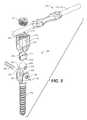
- the head 110can tilt from about 12 degrees to zero degrees where the head 110 is about parallel to the x axis and from zero degrees to 12 degrees about the y axis and on the other side of the x axis.
- the headcan tilt through about 24 degrees about the y axis.
- the head 110can swivel for a total of about 40 degrees about the x axis.
- the head 110can swivel about the x axis from about 20 degrees to one side of the z axis to zero degrees and from zero degrees to about 20 degrees on the other side of the z axis.
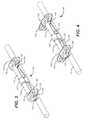
- the horizontal rod systemconnects to the heads of the anchor system without the vertical rod system connecting to the heads.
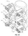
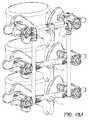
- two anchor systemsare secured to each vertebral level with a horizontal rod system connected between the two anchor systems. This further ensures that less stress and force is placed on the anchor systems secured to each level and also enables dynamic stability of the vertebra of the spine. Accordingly, movement of the vertebra relative to each other vertebra, as the spine extends, flexes, rotates and bends, is stabilized by the horizontal rods and the entire system 100 without placing excessive force or stress on the anchor system as there are no vertical rods that connect the anchor systems of one vertebra level with the anchor system of another vertebra.
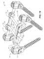
- FIG. 19 through FIG. 25another embodiment of the horizontal rod system 304 of the dynamic stabilization system 300 is depicted as used with an anchor system 102 of the embodiment depicted in FIG. 1 .
- the horizontal rod system 304includes first and second horizontal rods 308 , 310 .
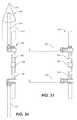
- FIG. 19Ashows a second image of only the horizontal rod 308 in a first undeployed position and that FIG. 19 shows a deployed position with the horizontal rod 308 connected with vertical rods 306 and, thus, the entire system 300 .
- the torsion rod and connector elements used in the horizontal rod embodiment of FIG. 1can be used with the horizontal rod of FIG. 33 .
- the connectoris secured to the platform of the horizontal rod of FIG. 33 with the two deflection rods or loading rods extending toward the ends of the horizontal rod of FIG. 33 and about parallel to that horizontal rod.
Landscapes
- Health & Medical Sciences (AREA)
- Orthopedic Medicine & Surgery (AREA)
- Life Sciences & Earth Sciences (AREA)
- Surgery (AREA)
- Neurology (AREA)
- Veterinary Medicine (AREA)
- Animal Behavior & Ethology (AREA)
- Nuclear Medicine, Radiotherapy & Molecular Imaging (AREA)
- Public Health (AREA)
- General Health & Medical Sciences (AREA)
- Engineering & Computer Science (AREA)
- Molecular Biology (AREA)
- Biomedical Technology (AREA)
- Medical Informatics (AREA)
- Heart & Thoracic Surgery (AREA)
- Medicinal Chemistry (AREA)
- Chemical Kinetics & Catalysis (AREA)
- General Chemical & Material Sciences (AREA)
- Chemical & Material Sciences (AREA)
- Organic Chemistry (AREA)
- Pharmacology & Pharmacy (AREA)
- Rheumatology (AREA)
- Pulmonology (AREA)
- Bioinformatics & Cheminformatics (AREA)
- Pain & Pain Management (AREA)
- Immunology (AREA)
- Physical Education & Sports Medicine (AREA)
- Surgical Instruments (AREA)
- Prostheses (AREA)
- Pharmaceuticals Containing Other Organic And Inorganic Compounds (AREA)
- Acyclic And Carbocyclic Compounds In Medicinal Compositions (AREA)
Abstract
Description
Claims (30)
Priority Applications (1)
| Application Number | Priority Date | Filing Date | Title |
|---|---|---|---|
| US11/832,377US8070774B2 (en) | 2007-06-05 | 2007-08-01 | Reinforced bone anchor for a dynamic stabilization and motion preservation spinal implantation system and method |
Applications Claiming Priority (2)
| Application Number | Priority Date | Filing Date | Title |
|---|---|---|---|
| US94216207P | 2007-06-05 | 2007-06-05 | |
| US11/832,377US8070774B2 (en) | 2007-06-05 | 2007-08-01 | Reinforced bone anchor for a dynamic stabilization and motion preservation spinal implantation system and method |
Publications (2)
| Publication Number | Publication Date |
|---|---|
| US20080306552A1 US20080306552A1 (en) | 2008-12-11 |
| US8070774B2true US8070774B2 (en) | 2011-12-06 |
Family
ID=40096581
Family Applications (23)
| Application Number | Title | Priority Date | Filing Date |
|---|---|---|---|
| US11/832,470Expired - Fee RelatedUS8048128B2 (en) | 2007-06-05 | 2007-08-01 | Revision system and method for a dynamic stabilization and motion preservation spinal implantation system and method |
| US11/832,562Expired - Fee RelatedUS8182516B2 (en) | 2007-06-05 | 2007-08-01 | Rod capture mechanism for dynamic stabilization and motion preservation spinal implantation system and method |
| US11/832,485Expired - Fee RelatedUS8118842B2 (en) | 2007-06-05 | 2007-08-01 | Multi-level dynamic stabilization and motion preservation spinal implantation system and method |
| US11/832,534Expired - Fee RelatedUS8147520B2 (en) | 2007-06-05 | 2007-08-01 | Horizontally loaded dynamic stabilization and motion preservation spinal implantation system and method |
| US11/832,436Expired - Fee RelatedUS8211150B2 (en) | 2007-06-05 | 2007-08-01 | Dynamic stabilization and motion preservation spinal implantation system and method |
| US11/832,527Expired - Fee RelatedUS8162987B2 (en) | 2007-06-05 | 2007-08-01 | Modular spine treatment kit for dynamic stabilization and motion preservation of the spine |
| US11/832,557Expired - Fee RelatedUS8080039B2 (en) | 2007-06-05 | 2007-08-01 | Anchor system for a spine implantation system that can move about three axes |
| US11/832,494Expired - Fee RelatedUS8182515B2 (en) | 2007-06-05 | 2007-08-01 | Dynamic stabilization and motion preservation spinal implantation system and method |
| US11/832,338Expired - Fee RelatedUS8070780B2 (en) | 2007-06-05 | 2007-08-01 | Bone anchor with a yoke-shaped anchor head for a dynamic stabilization and motion preservation spinal implantation system and method |
| US11/832,305Expired - Fee RelatedUS8002800B2 (en) | 2007-06-05 | 2007-08-01 | Horizontal rod with a mounting platform for a dynamic stabilization and motion preservation spinal implantation system and method |
| US11/832,400Active2028-02-22US7635380B2 (en) | 2007-06-05 | 2007-08-01 | Bone anchor with a compressor element for receiving a rod for a dynamic stabilization and motion preservation spinal implantation system and method |
| US11/832,446Expired - Fee RelatedUS8177815B2 (en) | 2007-06-05 | 2007-08-01 | Super-elastic deflection rod for a dynamic stabilization and motion preservation spinal implantation system and method |
| US11/832,413Expired - Fee RelatedUS8192469B2 (en) | 2007-06-05 | 2007-08-01 | Dynamic stabilization and motion preservation spinal implantation system and method with a deflection rod |
| US11/832,548Expired - Fee RelatedUS8142480B2 (en) | 2007-06-05 | 2007-08-01 | Dynamic stabilization and motion preservation spinal implantation system with horizontal deflection rod and articulating vertical rods |
| US11/832,426Expired - Fee RelatedUS8172881B2 (en) | 2007-06-05 | 2007-08-01 | Dynamic stabilization and motion preservation spinal implantation system and method with a deflection rod mounted in close proximity to a mounting rod |
| US11/832,358Expired - Fee RelatedUS8105356B2 (en) | 2007-06-05 | 2007-08-01 | Bone anchor with a curved mounting element for a dynamic stabilization and motion preservation spinal implantation system and method |
| US11/832,377Expired - Fee RelatedUS8070774B2 (en) | 2007-06-05 | 2007-08-01 | Reinforced bone anchor for a dynamic stabilization and motion preservation spinal implantation system and method |
| US11/832,330Expired - Fee RelatedUS8052721B2 (en) | 2007-06-05 | 2007-08-01 | Multi-dimensional horizontal rod for a dynamic stabilization and motion preservation spinal implantation system and method |
| US11/832,260Expired - Fee RelatedUS7942900B2 (en) | 2007-06-05 | 2007-08-01 | Shaped horizontal rod for dynamic stabilization and motion preservation spinal implantation system and method |
| US11/832,517Expired - Fee RelatedUS8066747B2 (en) | 2007-06-05 | 2007-08-01 | Implantation method for a dynamic stabilization and motion preservation spinal implantation system and method |
| US11/832,273Expired - Fee RelatedUS8012175B2 (en) | 2007-06-05 | 2007-08-01 | Multi-directional deflection profile for a dynamic stabilization and motion preservation spinal implantation system and method |
| US12/615,367Active2028-07-18US8568451B2 (en) | 2007-06-05 | 2009-11-10 | Bone anchor for receiving a rod for stabilization and motion preservation spinal implantation system and method |
| US12/615,380Expired - Fee RelatedUS8317836B2 (en) | 2007-06-05 | 2009-11-10 | Bone anchor for receiving a rod for stabilization and motion preservation spinal implantation system and method |
Family Applications Before (16)
| Application Number | Title | Priority Date | Filing Date |
|---|---|---|---|
| US11/832,470Expired - Fee RelatedUS8048128B2 (en) | 2007-06-05 | 2007-08-01 | Revision system and method for a dynamic stabilization and motion preservation spinal implantation system and method |
| US11/832,562Expired - Fee RelatedUS8182516B2 (en) | 2007-06-05 | 2007-08-01 | Rod capture mechanism for dynamic stabilization and motion preservation spinal implantation system and method |
| US11/832,485Expired - Fee RelatedUS8118842B2 (en) | 2007-06-05 | 2007-08-01 | Multi-level dynamic stabilization and motion preservation spinal implantation system and method |
| US11/832,534Expired - Fee RelatedUS8147520B2 (en) | 2007-06-05 | 2007-08-01 | Horizontally loaded dynamic stabilization and motion preservation spinal implantation system and method |
| US11/832,436Expired - Fee RelatedUS8211150B2 (en) | 2007-06-05 | 2007-08-01 | Dynamic stabilization and motion preservation spinal implantation system and method |
| US11/832,527Expired - Fee RelatedUS8162987B2 (en) | 2007-06-05 | 2007-08-01 | Modular spine treatment kit for dynamic stabilization and motion preservation of the spine |
| US11/832,557Expired - Fee RelatedUS8080039B2 (en) | 2007-06-05 | 2007-08-01 | Anchor system for a spine implantation system that can move about three axes |
| US11/832,494Expired - Fee RelatedUS8182515B2 (en) | 2007-06-05 | 2007-08-01 | Dynamic stabilization and motion preservation spinal implantation system and method |
| US11/832,338Expired - Fee RelatedUS8070780B2 (en) | 2007-06-05 | 2007-08-01 | Bone anchor with a yoke-shaped anchor head for a dynamic stabilization and motion preservation spinal implantation system and method |
| US11/832,305Expired - Fee RelatedUS8002800B2 (en) | 2007-06-05 | 2007-08-01 | Horizontal rod with a mounting platform for a dynamic stabilization and motion preservation spinal implantation system and method |
| US11/832,400Active2028-02-22US7635380B2 (en) | 2007-06-05 | 2007-08-01 | Bone anchor with a compressor element for receiving a rod for a dynamic stabilization and motion preservation spinal implantation system and method |
| US11/832,446Expired - Fee RelatedUS8177815B2 (en) | 2007-06-05 | 2007-08-01 | Super-elastic deflection rod for a dynamic stabilization and motion preservation spinal implantation system and method |
| US11/832,413Expired - Fee RelatedUS8192469B2 (en) | 2007-06-05 | 2007-08-01 | Dynamic stabilization and motion preservation spinal implantation system and method with a deflection rod |
| US11/832,548Expired - Fee RelatedUS8142480B2 (en) | 2007-06-05 | 2007-08-01 | Dynamic stabilization and motion preservation spinal implantation system with horizontal deflection rod and articulating vertical rods |
| US11/832,426Expired - Fee RelatedUS8172881B2 (en) | 2007-06-05 | 2007-08-01 | Dynamic stabilization and motion preservation spinal implantation system and method with a deflection rod mounted in close proximity to a mounting rod |
| US11/832,358Expired - Fee RelatedUS8105356B2 (en) | 2007-06-05 | 2007-08-01 | Bone anchor with a curved mounting element for a dynamic stabilization and motion preservation spinal implantation system and method |
Family Applications After (6)
| Application Number | Title | Priority Date | Filing Date |
|---|---|---|---|
| US11/832,330Expired - Fee RelatedUS8052721B2 (en) | 2007-06-05 | 2007-08-01 | Multi-dimensional horizontal rod for a dynamic stabilization and motion preservation spinal implantation system and method |
| US11/832,260Expired - Fee RelatedUS7942900B2 (en) | 2007-06-05 | 2007-08-01 | Shaped horizontal rod for dynamic stabilization and motion preservation spinal implantation system and method |
| US11/832,517Expired - Fee RelatedUS8066747B2 (en) | 2007-06-05 | 2007-08-01 | Implantation method for a dynamic stabilization and motion preservation spinal implantation system and method |
| US11/832,273Expired - Fee RelatedUS8012175B2 (en) | 2007-06-05 | 2007-08-01 | Multi-directional deflection profile for a dynamic stabilization and motion preservation spinal implantation system and method |
| US12/615,367Active2028-07-18US8568451B2 (en) | 2007-06-05 | 2009-11-10 | Bone anchor for receiving a rod for stabilization and motion preservation spinal implantation system and method |
| US12/615,380Expired - Fee RelatedUS8317836B2 (en) | 2007-06-05 | 2009-11-10 | Bone anchor for receiving a rod for stabilization and motion preservation spinal implantation system and method |
Country Status (3)
| Country | Link |
|---|---|
| US (23) | US8048128B2 (en) |
| BR (1) | BRPI0812221A2 (en) |
| TN (1) | TN2009000439A1 (en) |
Cited By (6)
| Publication number | Priority date | Publication date | Assignee | Title |
|---|---|---|---|---|
| US8317836B2 (en) | 2007-06-05 | 2012-11-27 | Spartek Medical, Inc. | Bone anchor for receiving a rod for stabilization and motion preservation spinal implantation system and method |
| US8394127B2 (en) | 2009-12-02 | 2013-03-12 | Spartek Medical, Inc. | Low profile spinal prosthesis incorporating a bone anchor having a deflectable post and a compound spinal rod |
| US8430916B1 (en) | 2012-02-07 | 2013-04-30 | Spartek Medical, Inc. | Spinal rod connectors, methods of use, and spinal prosthesis incorporating spinal rod connectors |
| US10149702B2 (en) | 2015-01-12 | 2018-12-11 | Imds Llc | Polyaxial screw and rod system |
| US10610265B1 (en) | 2017-07-31 | 2020-04-07 | K2M, Inc. | Polyaxial bone screw with increased angulation |
| US10687860B2 (en) | 2012-04-24 | 2020-06-23 | Retrospine Pty Ltd | Segmental correction of lumbar lordosis |
Families Citing this family (187)
| Publication number | Priority date | Publication date | Assignee | Title |
|---|---|---|---|---|
| US7833250B2 (en) | 2004-11-10 | 2010-11-16 | Jackson Roger P | Polyaxial bone screw with helically wound capture connection |
| US8353932B2 (en) | 2005-09-30 | 2013-01-15 | Jackson Roger P | Polyaxial bone anchor assembly with one-piece closure, pressure insert and plastic elongate member |
| US8292926B2 (en) | 2005-09-30 | 2012-10-23 | Jackson Roger P | Dynamic stabilization connecting member with elastic core and outer sleeve |
| US10729469B2 (en) | 2006-01-09 | 2020-08-04 | Roger P. Jackson | Flexible spinal stabilization assembly with spacer having off-axis core member |
| US10258382B2 (en) | 2007-01-18 | 2019-04-16 | Roger P. Jackson | Rod-cord dynamic connection assemblies with slidable bone anchor attachment members along the cord |
| US7862587B2 (en) | 2004-02-27 | 2011-01-04 | Jackson Roger P | Dynamic stabilization assemblies, tool set and method |
| US8876868B2 (en) | 2002-09-06 | 2014-11-04 | Roger P. Jackson | Helical guide and advancement flange with radially loaded lip |
| WO2006052796A2 (en) | 2004-11-10 | 2006-05-18 | Jackson Roger P | Helical guide and advancement flange with break-off extensions |
| US7621918B2 (en) | 2004-11-23 | 2009-11-24 | Jackson Roger P | Spinal fixation tool set and method |
| US7377923B2 (en) | 2003-05-22 | 2008-05-27 | Alphatec Spine, Inc. | Variable angle spinal screw assembly |
| US7766915B2 (en) | 2004-02-27 | 2010-08-03 | Jackson Roger P | Dynamic fixation assemblies with inner core and outer coil-like member |
| US8377102B2 (en)* | 2003-06-18 | 2013-02-19 | Roger P. Jackson | Polyaxial bone anchor with spline capture connection and lower pressure insert |
| US8137386B2 (en) | 2003-08-28 | 2012-03-20 | Jackson Roger P | Polyaxial bone screw apparatus |
| US8366753B2 (en) | 2003-06-18 | 2013-02-05 | Jackson Roger P | Polyaxial bone screw assembly with fixed retaining structure |
| US8926670B2 (en) | 2003-06-18 | 2015-01-06 | Roger P. Jackson | Polyaxial bone screw assembly |
| US7776067B2 (en) | 2005-05-27 | 2010-08-17 | Jackson Roger P | Polyaxial bone screw with shank articulation pressure insert and method |
| US7967850B2 (en) | 2003-06-18 | 2011-06-28 | Jackson Roger P | Polyaxial bone anchor with helical capture connection, insert and dual locking assembly |
| US8398682B2 (en) | 2003-06-18 | 2013-03-19 | Roger P. Jackson | Polyaxial bone screw assembly |
| US8092500B2 (en) | 2007-05-01 | 2012-01-10 | Jackson Roger P | Dynamic stabilization connecting member with floating core, compression spacer and over-mold |
| US7527638B2 (en) | 2003-12-16 | 2009-05-05 | Depuy Spine, Inc. | Methods and devices for minimally invasive spinal fixation element placement |
| US11419642B2 (en) | 2003-12-16 | 2022-08-23 | Medos International Sarl | Percutaneous access devices and bone anchor assemblies |
| US7179261B2 (en) | 2003-12-16 | 2007-02-20 | Depuy Spine, Inc. | Percutaneous access devices and bone anchor assemblies |
| FR2865373B1 (en)* | 2004-01-27 | 2006-03-03 | Medicrea International | MATERIAL OF VERTEBRAL OSTEOSYNTHESIS |
| US8333789B2 (en)* | 2007-01-10 | 2012-12-18 | Gmedelaware 2 Llc | Facet joint replacement |
| US11241261B2 (en) | 2005-09-30 | 2022-02-08 | Roger P Jackson | Apparatus and method for soft spinal stabilization using a tensionable cord and releasable end structure |
| JP2007525274A (en) | 2004-02-27 | 2007-09-06 | ロジャー・ピー・ジャクソン | Orthopedic implant rod reduction instrument set and method |
| US8152810B2 (en) | 2004-11-23 | 2012-04-10 | Jackson Roger P | Spinal fixation tool set and method |
| US7160300B2 (en) | 2004-02-27 | 2007-01-09 | Jackson Roger P | Orthopedic implant rod reduction tool set and method |
| DE102004010380A1 (en)* | 2004-03-03 | 2005-09-22 | Biedermann Motech Gmbh | Anchoring element and stabilizing device for the dynamic stabilization of vertebrae or bones with such an anchoring element |
| US7651502B2 (en) | 2004-09-24 | 2010-01-26 | Jackson Roger P | Spinal fixation tool set and method for rod reduction and fastener insertion |
| US8926672B2 (en) | 2004-11-10 | 2015-01-06 | Roger P. Jackson | Splay control closure for open bone anchor |
| US9216041B2 (en) | 2009-06-15 | 2015-12-22 | Roger P. Jackson | Spinal connecting members with tensioned cords and rigid sleeves for engaging compression inserts |
| US8308782B2 (en) | 2004-11-23 | 2012-11-13 | Jackson Roger P | Bone anchors with longitudinal connecting member engaging inserts and closures for fixation and optional angulation |
| US9980753B2 (en) | 2009-06-15 | 2018-05-29 | Roger P Jackson | pivotal anchor with snap-in-place insert having rotation blocking extensions |
| WO2006057837A1 (en) | 2004-11-23 | 2006-06-01 | Jackson Roger P | Spinal fixation tool attachment structure |
| US8444681B2 (en) | 2009-06-15 | 2013-05-21 | Roger P. Jackson | Polyaxial bone anchor with pop-on shank, friction fit retainer and winged insert |
| US9168069B2 (en) | 2009-06-15 | 2015-10-27 | Roger P. Jackson | Polyaxial bone anchor with pop-on shank and winged insert with lower skirt for engaging a friction fit retainer |
| DE102005005647A1 (en)* | 2005-02-08 | 2006-08-17 | Henning Kloss | Pedicle screw for spinal column stabilizing device, has screw head with two opposed oblong hole shaped recesses, and ball unit including recess for accommodating connecting unit and movably mounted in head |
| US7896905B2 (en)* | 2005-02-09 | 2011-03-01 | David Lee | Bone fixation apparatus |
| US7901437B2 (en) | 2007-01-26 | 2011-03-08 | Jackson Roger P | Dynamic stabilization member with molded connection |
| US10076361B2 (en) | 2005-02-22 | 2018-09-18 | Roger P. Jackson | Polyaxial bone screw with spherical capture, compression and alignment and retention structures |
| US7955358B2 (en) | 2005-09-19 | 2011-06-07 | Albert Todd J | Bone screw apparatus, system and method |
| US8105368B2 (en) | 2005-09-30 | 2012-01-31 | Jackson Roger P | Dynamic stabilization connecting member with slitted core and outer sleeve |
| US8075599B2 (en) | 2005-10-18 | 2011-12-13 | Warsaw Orthopedic, Inc. | Adjustable bone anchor assembly |
| US8002806B2 (en)* | 2005-10-20 | 2011-08-23 | Warsaw Orthopedic, Inc. | Bottom loading multi-axial screw assembly |
| GB0521582D0 (en) | 2005-10-22 | 2005-11-30 | Depuy Int Ltd | An implant for supporting a spinal column |
| US8100946B2 (en) | 2005-11-21 | 2012-01-24 | Synthes Usa, Llc | Polyaxial bone anchors with increased angulation |
| US9907580B2 (en) | 2005-11-22 | 2018-03-06 | Bryson Medical Technology Llc | Adjustable spinous process spacer device and method of treating spinal disorders |
| US7517359B2 (en)* | 2005-12-20 | 2009-04-14 | Sdgi Holdings, Inc. | Vertebral rod assemblies and methods |
| GB0600662D0 (en) | 2006-01-13 | 2006-02-22 | Depuy Int Ltd | Spinal support rod kit |
| US8348952B2 (en) | 2006-01-26 | 2013-01-08 | Depuy International Ltd. | System and method for cooling a spinal correction device comprising a shape memory material for corrective spinal surgery |
| FR2901687B1 (en)* | 2006-05-30 | 2008-12-19 | Arthroplastie Diffusion Sarl | BONE FASTENING DEVICE |
| CA2670988C (en) | 2006-12-08 | 2014-03-25 | Roger P. Jackson | Tool system for dynamic spinal implants |
| US8366745B2 (en) | 2007-05-01 | 2013-02-05 | Jackson Roger P | Dynamic stabilization assembly having pre-compressed spacers with differential displacements |
| US8475498B2 (en) | 2007-01-18 | 2013-07-02 | Roger P. Jackson | Dynamic stabilization connecting member with cord connection |
| US10792074B2 (en) | 2007-01-22 | 2020-10-06 | Roger P. Jackson | Pivotal bone anchor assemly with twist-in-place friction fit insert |
| US8012177B2 (en) | 2007-02-12 | 2011-09-06 | Jackson Roger P | Dynamic stabilization assembly with frusto-conical connection |
| US10383660B2 (en) | 2007-05-01 | 2019-08-20 | Roger P. Jackson | Soft stabilization assemblies with pretensioned cords |
| US8979904B2 (en) | 2007-05-01 | 2015-03-17 | Roger P Jackson | Connecting member with tensioned cord, low profile rigid sleeve and spacer with torsion control |
| US10758283B2 (en) | 2016-08-11 | 2020-09-01 | Mighty Oak Medical, Inc. | Fixation devices having fenestrations and methods for using the same |
| US9439681B2 (en) | 2007-07-20 | 2016-09-13 | DePuy Synthes Products, Inc. | Polyaxial bone fixation element |
| US8057518B2 (en)* | 2007-08-31 | 2011-11-15 | Depuy Spine, Inc. | Spanning connector for connecting a spinal fixation element and an offset bone anchor |
| US20090069849A1 (en)* | 2007-09-10 | 2009-03-12 | Oh Younghoon | Dynamic screw system |
| FR2920959B1 (en)* | 2007-09-17 | 2010-09-10 | Clariance | VERTEBRAL ANCHORING DEVICE. |
| GB0720762D0 (en)* | 2007-10-24 | 2007-12-05 | Depuy Spine Sorl | Assembly for orthopaedic surgery |
| EP2211742A4 (en) | 2007-10-24 | 2012-12-19 | Nuvasive Inc | Surgical fixation system and related methods |
| US8197515B2 (en)* | 2008-02-18 | 2012-06-12 | Expanding Orthopedics Inc. | Cross-connector assembly |
| KR100895243B1 (en)* | 2008-02-27 | 2009-04-30 | 최길운 | Buffered pedicle screws |
| US9060813B1 (en) | 2008-02-29 | 2015-06-23 | Nuvasive, Inc. | Surgical fixation system and related methods |
| US8092495B2 (en)* | 2008-04-04 | 2012-01-10 | The Cleveland Clinic Foundation | Spinal platform and method for delivering a therapeutic agent to a spinal cord target |
| FR2931054A1 (en)* | 2008-05-13 | 2009-11-20 | Warsaw Orthopedic Inc | SPINAL CONNECTOR SYSTEM AND SPINAL SURGICAL SYSTEM USING THE SAME |
| AU2010260521C1 (en) | 2008-08-01 | 2013-08-01 | Roger P. Jackson | Longitudinal connecting member with sleeved tensioned cords |
| WO2010028070A1 (en)* | 2008-09-02 | 2010-03-11 | Life Spine, Inc. | Peek spinal mesh and peek spinal mesh applicator |
| EP2484300B1 (en)* | 2008-09-05 | 2015-05-20 | Biedermann Technologies GmbH & Co. KG | Stabilization device for bones, in particular for the spinal column |
| JP5815407B2 (en) | 2008-09-12 | 2015-11-17 | ジンテス ゲゼルシャフト ミット ベシュレンクテル ハフツング | Spinal stabilization and guided fixation system |
| KR20110081208A (en) | 2008-09-29 | 2011-07-13 | 신세스 게엠바하 | Multi-Axis Bottom-Loading Screw and Rod Assemblies |
| US10383659B2 (en)* | 2008-10-10 | 2019-08-20 | Globus Medical, Inc. | Uniplanar screw |
| CA2742399A1 (en)* | 2008-11-03 | 2010-06-03 | Dustin M. Harvey | Uni-planar bone fixation assembly |
| US8177814B2 (en)* | 2009-02-26 | 2012-05-15 | Life Spine, Inc. | Posterior spinal bridge assembly providing static or dynamic N-level spinal bridge interconnection |
| US9351767B2 (en)* | 2009-03-24 | 2016-05-31 | Life Spine, Inc. | Supplementary spinal fixation/stabilization apparatus with dynamic inter-vertebral connection |
| KR20120013312A (en) | 2009-04-15 | 2012-02-14 | 신세스 게엠바하 | Orthodontic Connectors for Spinal Structures |
| US20100292739A1 (en)* | 2009-05-15 | 2010-11-18 | Warsaw Orthopedic, Inc. | Bone Screws With Improved Locking Mechanisms |
| US8998959B2 (en) | 2009-06-15 | 2015-04-07 | Roger P Jackson | Polyaxial bone anchors with pop-on shank, fully constrained friction fit retainer and lock and release insert |
| CN103826560A (en) | 2009-06-15 | 2014-05-28 | 罗杰.P.杰克逊 | Polyaxial Bone Anchor with Socket Stem and Winged Inserts with Friction Fit Compression Collars |
| US9668771B2 (en) | 2009-06-15 | 2017-06-06 | Roger P Jackson | Soft stabilization assemblies with off-set connector |
| US11229457B2 (en) | 2009-06-15 | 2022-01-25 | Roger P. Jackson | Pivotal bone anchor assembly with insert tool deployment |
| CA2764841A1 (en) | 2009-06-17 | 2010-12-23 | Synthes Usa, Llc | Revision connector for spinal constructs |
| USD642268S1 (en)* | 2009-08-26 | 2011-07-26 | Theken Spine, Llc | Hex rod for spinal surgery |
| US9211144B2 (en) | 2009-09-09 | 2015-12-15 | Globus Medical, Inc. | Spine surgery device and method |
| EP2485654B1 (en) | 2009-10-05 | 2021-05-05 | Jackson P. Roger | Polyaxial bone anchor with non-pivotable retainer and pop-on shank, some with friction fit |
| US20110098748A1 (en)* | 2009-10-26 | 2011-04-28 | Warsaw Orthopedic, Inc. | Adjustable vertebral rod system and methods of use |
| US8298275B2 (en)* | 2009-10-30 | 2012-10-30 | Warsaw Orthopedic, Inc. | Direct control spinal implant |
| US8430917B2 (en)* | 2009-10-30 | 2013-04-30 | Warsaw Orthopedic, Inc. | Bone engaging implant with adjustment saddle |
| US20110106173A1 (en)* | 2009-10-30 | 2011-05-05 | Warsaw Orthopedic, Inc. | Anchor Assembly With Directionally Controlled Saddle Adjustment And Transversely Adjustable Receiver |
| US8449578B2 (en)* | 2009-11-09 | 2013-05-28 | Ebi, Llc | Multiplanar bone anchor system |
| US9044272B2 (en) | 2009-11-09 | 2015-06-02 | Ebi, Llc | Multiplanar bone anchor system |
| US20110202094A1 (en)* | 2009-11-11 | 2011-08-18 | Pereira Mario L | Trans-polyaxial screw |
| US8419778B2 (en) | 2010-01-15 | 2013-04-16 | Ebi, Llc | Uniplanar bone anchor system |
| US8647370B2 (en)* | 2010-01-15 | 2014-02-11 | Ebi, Llc | Uniplanar bone anchor system |
| US8617216B2 (en)* | 2010-04-05 | 2013-12-31 | David L. Brumfield | Fully-adjustable bone fixation device |
| WO2011127065A1 (en) | 2010-04-06 | 2011-10-13 | Seaspine, Inc. | System and methods for correcting spinal deformities |
| DE102010016854A1 (en) | 2010-05-10 | 2011-11-10 | Ulrich Gmbh & Co. Kg | Retaining device for vertebral bodies of the spine |
| US12383311B2 (en) | 2010-05-14 | 2025-08-12 | Roger P. Jackson | Pivotal bone anchor assembly and method for use thereof |
| WO2017066518A1 (en) | 2010-06-29 | 2017-04-20 | Mighty Oak Medical, Inc. | Patient-matched apparatus and methods for performing surgical procedures |
| US11376073B2 (en) | 2010-06-29 | 2022-07-05 | Mighty Oak Medical Inc. | Patient-matched apparatus and methods for performing surgical procedures |
| US12357413B2 (en) | 2010-06-29 | 2025-07-15 | Mighty Oak Medical, Inc. | Patient-matched apparatus for use in spine related surgical procedures and methods for using the same |
| US11806197B2 (en) | 2010-06-29 | 2023-11-07 | Mighty Oak Medical, Inc. | Patient-matched apparatus for use in spine related surgical procedures and methods for using the same |
| US11039889B2 (en) | 2010-06-29 | 2021-06-22 | Mighty Oak Medical, Inc. | Patient-matched apparatus and methods for performing surgical procedures |
| US9642633B2 (en) | 2010-06-29 | 2017-05-09 | Mighty Oak Medical, Inc. | Patient-matched apparatus and methods for performing surgical procedures |
| US9084634B1 (en) | 2010-07-09 | 2015-07-21 | Theken Spine, Llc | Uniplanar screw |
| US10603083B1 (en) | 2010-07-09 | 2020-03-31 | Theken Spine, Llc | Apparatus and method for limiting a range of angular positions of a screw |
| US8979901B2 (en) | 2010-08-26 | 2015-03-17 | Warsaw Orthopedic, Inc. | Dynamic bone fastener with a preset range of motion |
| US9072546B2 (en)* | 2010-08-26 | 2015-07-07 | Warsaw Orthopedic, Inc. | Spinal constructs with improved load-sharing |
| AU2011299558A1 (en) | 2010-09-08 | 2013-05-02 | Roger P. Jackson | Dynamic stabilization members with elastic and inelastic sections |
| US9232969B2 (en)* | 2010-10-29 | 2016-01-12 | Warsaw Orthopedic, Inc. | Directional control for a multi-axial screw assembly |
| AU2011324058A1 (en) | 2010-11-02 | 2013-06-20 | Roger P. Jackson | Polyaxial bone anchor with pop-on shank and pivotable retainer |
| US8721566B2 (en)* | 2010-11-12 | 2014-05-13 | Robert A. Connor | Spinal motion measurement device |
| EP2455014B1 (en)* | 2010-11-17 | 2015-08-12 | Hyprevention | Implantable device for preventive or interventive treatment of femur fractures, associated ancillary device |
| US20120215263A1 (en)* | 2011-02-23 | 2012-08-23 | Choon Sung Lee | Extensible pedicle screw coupling device |
| US20120221056A1 (en)* | 2011-02-24 | 2012-08-30 | Alphatec Spine, Inc. | Apparatus for linking implants and reducing deformities |
| US9387013B1 (en) | 2011-03-01 | 2016-07-12 | Nuvasive, Inc. | Posterior cervical fixation system |
| US8337530B2 (en)* | 2011-03-09 | 2012-12-25 | Zimmer Spine, Inc. | Polyaxial pedicle screw with increased angulation |
| JP5865479B2 (en) | 2011-03-24 | 2016-02-17 | ロジャー・ピー・ジャクソン | Multiaxial bone anchor with compound joint and pop-mounted shank |
| US20120290013A1 (en)* | 2011-03-24 | 2012-11-15 | Peter Melott Simonson | Tapered spinal rod |
| US9005292B2 (en) | 2011-05-10 | 2015-04-14 | Hooman M. MELAMED | Vertebral spacer |
| US9149306B2 (en) | 2011-06-21 | 2015-10-06 | Seaspine, Inc. | Spinous process device |
| USD775335S1 (en)* | 2011-06-29 | 2016-12-27 | Mighty Oak Medical, Inc. | Multi-level surgical guide |
| US8852241B2 (en) | 2011-08-04 | 2014-10-07 | Devin Datta | Surgical devices and methods providing sacroiliac stabilization |
| US20130103086A1 (en)* | 2011-10-19 | 2013-04-25 | Warsaw Orthopedic, Inc. | Spinous process mounted spinal implant |
| US20130123854A1 (en)* | 2011-11-16 | 2013-05-16 | Dimitriy G. Kondrashov | System and method for spinal stabilization through mutli-head spinal screws |
| US8911479B2 (en) | 2012-01-10 | 2014-12-16 | Roger P. Jackson | Multi-start closures for open implants |
| US9101405B2 (en)* | 2012-02-10 | 2015-08-11 | Warsaw Orthopedic, Inc. | Vertebral implant and connector |
| US8470009B1 (en)* | 2012-03-08 | 2013-06-25 | Warsaw Orthopedic, Inc. | Bone fastener and method of use |
| US10327818B2 (en) | 2012-06-18 | 2019-06-25 | Bruce Francis Hodgson | Method and apparatus for the treatment of scoliosis |
| CA2903160A1 (en)* | 2012-06-18 | 2014-12-27 | Bruce Francis HODGSON | Method and apparatus for the treatment of scoliosis |
| EP2689734B1 (en) | 2012-07-27 | 2016-09-14 | Biedermann Technologies GmbH & Co. KG | Polyaxial bone anchoring device with enlarged pivot angle |
| US9295488B2 (en) | 2012-08-09 | 2016-03-29 | Wilson T. Asfora | Joint fusion |
| US20140074169A1 (en)* | 2012-09-13 | 2014-03-13 | Warsaw Orthopedic, Inc. | Spinal correction system and method |
| US9023087B2 (en)* | 2012-11-09 | 2015-05-05 | Blackstone Medical, Inc. | Percutaneous modular head-to-head cross connector |
| US9561064B2 (en) | 2012-11-21 | 2017-02-07 | Pioneer Surgical Technology, Inc. | Bone plate system and method |
| US10765465B2 (en) | 2012-11-21 | 2020-09-08 | A&E Advanced Closure Systems, Llc | Tensioning instrument |
| US8911478B2 (en) | 2012-11-21 | 2014-12-16 | Roger P. Jackson | Splay control closure for open bone anchor |
| US10058354B2 (en) | 2013-01-28 | 2018-08-28 | Roger P. Jackson | Pivotal bone anchor assembly with frictional shank head seating surfaces |
| US9579125B2 (en) | 2013-02-09 | 2017-02-28 | Vertiscrew, Llc | Bone screw |
| US9463047B2 (en) | 2013-02-09 | 2016-10-11 | Vertiscrew, Llc | Bone screw |
| US8852239B2 (en) | 2013-02-15 | 2014-10-07 | Roger P Jackson | Sagittal angle screw with integral shank and receiver |
| US10154861B2 (en)* | 2013-03-15 | 2018-12-18 | Jcbd, Llc | Spinal stabilization system |
| US9510872B2 (en) | 2013-03-15 | 2016-12-06 | Jcbd, Llc | Spinal stabilization system |
| WO2014169189A1 (en)* | 2013-04-12 | 2014-10-16 | Alphatec Spine, Inc. | Uniplanar screw assembly and methods of use |
| CN106659524B (en)* | 2013-06-07 | 2019-02-12 | 乔治·弗雷 | Patient-matched instrument and method for performing surgical procedures |
| WO2015023420A2 (en) | 2013-07-25 | 2015-02-19 | Latitude Holdings, Llc | Percutaneous pedicle screw revision system |
| US9987047B2 (en) | 2013-10-07 | 2018-06-05 | Spine Wave, Inc. | Translating polyaxial screw |
| US9566092B2 (en) | 2013-10-29 | 2017-02-14 | Roger P. Jackson | Cervical bone anchor with collet retainer and outer locking sleeve |
| US9999454B2 (en) | 2013-12-05 | 2018-06-19 | A&E Advanced Closure Systems, Llc | Bone plate system and method |
| US9717533B2 (en) | 2013-12-12 | 2017-08-01 | Roger P. Jackson | Bone anchor closure pivot-splay control flange form guide and advancement structure |
| US9451993B2 (en) | 2014-01-09 | 2016-09-27 | Roger P. Jackson | Bi-radial pop-on cervical bone anchor |
| US10314635B2 (en) | 2014-05-28 | 2019-06-11 | A&E Advanced Closure Systems, Llc | Tensioning instruments |
| US9597119B2 (en) | 2014-06-04 | 2017-03-21 | Roger P. Jackson | Polyaxial bone anchor with polymer sleeve |
| US10064658B2 (en) | 2014-06-04 | 2018-09-04 | Roger P. Jackson | Polyaxial bone anchor with insert guides |
| EP3193755B1 (en) | 2014-09-19 | 2022-02-09 | In Queue Innovations, LLC | Fusion systems of assembly and use |
| BR112017005408B1 (en)* | 2014-09-19 | 2022-05-10 | Duet Spine Holdings, Llc | Single-level fusion system and assembly method thereof |
| US9763703B2 (en) | 2015-05-05 | 2017-09-19 | Degen Medical, Inc. | Cross connectors, kits, and methods |
| ES1143158Y (en)* | 2015-07-31 | 2015-11-26 | Inst Catala D Especialitats Odontologiques S L | PERFECTED SHOCK ABSORBER DEVICE FOR DENTAL IMPLANTS AND PROTESIS |
| WO2017040115A1 (en) | 2015-08-28 | 2017-03-09 | Cardiac Pacemakers, Inc. | System for detecting tamponade |
| US10265104B2 (en) | 2015-09-23 | 2019-04-23 | Deniz Ufuk Erbulut | Pedicle screw |
| US9603634B1 (en) | 2015-11-13 | 2017-03-28 | Amendia, Inc. | Percutaneous rod-to-rod cross connector |
| US10034691B1 (en) | 2015-12-03 | 2018-07-31 | Nuvasive, Inc. | Bone anchor |
| ES2878182T3 (en) | 2015-12-17 | 2021-11-18 | Ali Fahir Ozer | Double-headed pedicle screw |
| EP3405131B1 (en) | 2016-01-22 | 2023-07-19 | A&E Advanced Closure Systems, LLC | Bone plate having a connector and a connector for a surgical loop |
| CA3031931C (en) | 2016-07-29 | 2022-10-04 | A&E Advanced Closure Systems, Llc | Surgical cable tensioner |
| US10743890B2 (en) | 2016-08-11 | 2020-08-18 | Mighty Oak Medical, Inc. | Drill apparatus and surgical fixation devices and methods for using the same |
| US12016573B2 (en) | 2016-08-11 | 2024-06-25 | Mighty Oak Medical, Inc. | Drill apparatus and surgical fixation devices and methods for using the same |
| US9887489B1 (en) | 2016-10-19 | 2018-02-06 | Hubbell Incorporated | Electrical connector with plug latching assembly |
| USD864702S1 (en)* | 2017-05-09 | 2019-10-29 | Julius Blum Gmbh | Dowel |
| US11058510B2 (en)* | 2017-09-22 | 2021-07-13 | The Governors Of The University Of Alberta | Spine-mounted stereotactic systems and related methods |
| US10507043B1 (en) | 2017-10-11 | 2019-12-17 | Seaspine Orthopedics Corporation | Collet for a polyaxial screw assembly |
| USD857893S1 (en) | 2017-10-26 | 2019-08-27 | Mighty Oak Medical, Inc. | Cortical surgical guide |
| USD858765S1 (en) | 2017-10-26 | 2019-09-03 | Mighty Oak Medical, Inc. | Cortical surgical guide |
| USD948717S1 (en) | 2018-06-04 | 2022-04-12 | Mighty Oak Medical, Inc. | Sacro-iliac guide |
| USD895111S1 (en) | 2018-06-04 | 2020-09-01 | Mighty Oak Medical, Inc. | Sacro-iliac guide |
| US20220160400A1 (en)* | 2019-03-12 | 2022-05-26 | Carbofix Spine Inc. | Composite material spinal implant |
| JP7487222B2 (en) | 2019-03-26 | 2024-05-20 | マイティ オーク メディカル、インコーポレイテッド | Patient-adapted device for use in augmented reality assisted surgery and method for using same - Patents.com |
| EP3878386B1 (en) | 2020-03-12 | 2023-08-30 | Biedermann Technologies GmbH & Co. KG | Coupling device for use with a bone anchoring element and bone anchoring device with such a coupling device |
| US20250186088A1 (en)* | 2021-08-26 | 2025-06-12 | Orthopediatrics Corp. | Guided growth spinal implants |
| US12226131B2 (en) | 2021-10-18 | 2025-02-18 | Charles KANALY | Spinal fixation tool, system and method |
| JP2024538236A (en)* | 2021-10-28 | 2024-10-18 | アキュームド・エルエルシー | Anchor insertion system for winged bone anchors having a driving core - Patents.com |
| USD1045082S1 (en)* | 2022-01-18 | 2024-10-01 | Mirus Llc | Rod attachment extension |
Citations (497)
| Publication number | Priority date | Publication date | Assignee | Title |
|---|---|---|---|---|
| GB780652A (en) | 1954-04-30 | 1957-08-07 | Zimmer Orthopaedic Ltd | Improvements in or relating to apparatus for use in spinal fixation |
| US4041939A (en) | 1975-04-28 | 1977-08-16 | Downs Surgical Limited | Surgical implant spinal screw |
| US4065817A (en) | 1975-04-22 | 1978-01-03 | Per Ingvar Branemark | Bone prosthesis and method of forming a bone joint |
| DE2649042B1 (en) | 1976-10-28 | 1978-01-05 | Ulrich Max Bernhard | Corrective implant for anterior derotation spondylodesis and device for adjusting the corrective implant |
| US4347845A (en) | 1981-03-23 | 1982-09-07 | Mayfield Jack K | Hook inserter device |
| US4369770A (en) | 1980-07-30 | 1983-01-25 | Wyzsza Szkola Inzynierska Im. J. Gagarina | Surgical strut for treatment of the back-bone |
| US4382438A (en) | 1979-09-11 | 1983-05-10 | Synthes Ag | Instrument for treatment of spinal fractures, scoliosis and the like |
| US4409968A (en) | 1980-02-04 | 1983-10-18 | Drummond Denis S | Method and apparatus for engaging a hook assembly to a spinal column |
| US4411259A (en) | 1980-02-04 | 1983-10-25 | Drummond Denis S | Apparatus for engaging a hook assembly to a spinal column |
| US4422451A (en) | 1982-03-22 | 1983-12-27 | Ali Kalamchi | Spinal compression and distraction instrumentation |
| US4479491A (en) | 1982-07-26 | 1984-10-30 | Martin Felix M | Intervertebral stabilization implant |
| EP0128058A1 (en) | 1983-05-04 | 1984-12-12 | SOCIETE DE FABRICATION DE MATERIEL ORTHOPEDIQUE SOFAMOR Société à responsabilité limitée dite: | Spinal fixation device |
| US4567885A (en) | 1981-11-03 | 1986-02-04 | Androphy Gary W | Triplanar knee resection system |
| US4573454A (en) | 1984-05-17 | 1986-03-04 | Hoffman Gregory A | Spinal fixation apparatus |
| US4604995A (en) | 1984-03-30 | 1986-08-12 | Stephens David C | Spinal stabilizer |
| US4611581A (en) | 1983-12-16 | 1986-09-16 | Acromed Corporation | Apparatus for straightening spinal columns |
| US4611582A (en) | 1983-12-27 | 1986-09-16 | Wisconsin Alumni Research Foundation | Vertebral clamp |
| US4611580A (en) | 1983-11-23 | 1986-09-16 | Henry Ford Hospital | Intervertebral body stabilization |
| US4648388A (en) | 1985-11-01 | 1987-03-10 | Acromed Corporation | Apparatus and method for maintaining vertebrae in a desired relationship |
| US4653481A (en) | 1985-07-24 | 1987-03-31 | Howland Robert S | Advanced spine fixation system and method |
| US4653489A (en) | 1984-04-02 | 1987-03-31 | Tronzo Raymond G | Fenestrated hip screw and method of augmented fixation |
| US4655199A (en) | 1985-03-29 | 1987-04-07 | Acromed Corporation | Spinal column straightening apparatus |
| US4658809A (en) | 1983-02-25 | 1987-04-21 | Firma Heinrich C. Ulrich | Implantable spinal distraction splint |
| US4696290A (en) | 1983-12-16 | 1987-09-29 | Acromed Corporation | Apparatus for straightening spinal columns |
| GB2173104B (en) | 1984-02-28 | 1987-11-25 | Peter John Webb | Spinal fixation apparatus |
| US4719905A (en) | 1985-11-01 | 1988-01-19 | Acromed Corporation | Apparatus and method for maintaining vertebrae in a desired relationship |
| DE3639810A1 (en) | 1986-11-21 | 1988-05-26 | Heinrich Ulrich | Implant for correction and/or stabilisation of the spine |
| FR2612070A1 (en) | 1987-03-12 | 1988-09-16 | Privat Jean Marie | Posterior spinal osteosynthesis device |
| US4773402A (en) | 1985-09-13 | 1988-09-27 | Isola Implants, Inc. | Dorsal transacral surgical implant |
| FR2615095A1 (en) | 1987-05-15 | 1988-11-18 | Fabrication Materiel Orthopedi | Osteosynthesis instrumentation for the correction of lumbar scoliosis through the posterior |
| US4805602A (en) | 1986-11-03 | 1989-02-21 | Danninger Medical Technology | Transpedicular screw and rod system |
| US4887595A (en) | 1987-07-29 | 1989-12-19 | Acromed Corporation | Surgically implantable device for spinal columns |
| US4913134A (en) | 1987-07-24 | 1990-04-03 | Biotechnology, Inc. | Spinal fixation system |
| US4946458A (en) | 1986-04-25 | 1990-08-07 | Harms Juergen | Pedicle screw |
| US4950269A (en) | 1988-06-13 | 1990-08-21 | Acromed Corporation | Spinal column fixation device |
| US4955885A (en) | 1988-12-21 | 1990-09-11 | Zimmer, Inc. | Surgical slider instrument and method of using instrument |
| US4987892A (en) | 1989-04-04 | 1991-01-29 | Krag Martin H | Spinal fixation device |
| US5005562A (en) | 1988-06-24 | 1991-04-09 | Societe De Fabrication De Material Orthopedique | Implant for spinal osteosynthesis device, in particular in traumatology |
| US5024213A (en) | 1989-02-08 | 1991-06-18 | Acromed Corporation | Connector for a corrective device |
| US5030220A (en) | 1990-03-29 | 1991-07-09 | Advanced Spine Fixation Systems Incorporated | Spine fixation system |
| US5042982A (en) | 1987-07-08 | 1991-08-27 | Harms Juergen | Positioning device |
| US5047029A (en) | 1988-06-10 | 1991-09-10 | Synthes (U.S.A.) | Clamp and system for internal fixation |
| US5067955A (en) | 1989-04-13 | 1991-11-26 | Societe De Fabrication De Material Orthopedique | Vertebral implant for osteosynthesis device |
| US5074864A (en) | 1988-12-21 | 1991-12-24 | Zimmer, Inc. | Clamp assembly for use in a spinal system |
| US5084049A (en) | 1989-02-08 | 1992-01-28 | Acromed Corporation | Transverse connector for spinal column corrective devices |
| US5092866A (en) | 1989-02-03 | 1992-03-03 | Breard Francis H | Flexible inter-vertebral stabilizer as well as process and apparatus for determining or verifying its tension before installation on the spinal column |
| US5102412A (en) | 1990-06-19 | 1992-04-07 | Chaim Rogozinski | System for instrumentation of the spine in the treatment of spinal deformities |
| US5112332A (en) | 1988-12-21 | 1992-05-12 | Zimmer, Inc. | Method of performing spinal surgery |
| US5113685A (en) | 1991-01-28 | 1992-05-19 | Acromed Corporation | Apparatus for contouring spine plates and/or rods |
| US5127912A (en) | 1990-10-05 | 1992-07-07 | R. Charles Ray | Sacral implant system |
| US5129900A (en) | 1990-07-24 | 1992-07-14 | Acromed Corporation | Spinal column retaining method and apparatus |
| US5129388A (en) | 1989-02-09 | 1992-07-14 | Vignaud Jean Louis | Device for supporting the spinal column |
| US5147359A (en) | 1988-12-21 | 1992-09-15 | Zimmer, Inc. | Spinal hook body |
| US5154718A (en) | 1988-12-21 | 1992-10-13 | Zimmer, Inc. | Spinal coupler assembly |
| US5176680A (en) | 1990-02-08 | 1993-01-05 | Vignaud Jean Louis | Device for the adjustable fixing of spinal osteosynthesis rods |
| US5180393A (en) | 1990-09-21 | 1993-01-19 | Polyclinique De Bourgogne & Les Hortensiad | Artificial ligament for the spine |
| US5190543A (en) | 1990-11-26 | 1993-03-02 | Synthes (U.S.A.) | Anchoring device |
| US5201734A (en) | 1988-12-21 | 1993-04-13 | Zimmer, Inc. | Spinal locking sleeve assembly |
| US5207678A (en) | 1989-07-20 | 1993-05-04 | Prufer | Pedicle screw and receiver member therefore |
| US5261912A (en) | 1990-08-21 | 1993-11-16 | Synthes (U.S.A.) | Implant for an osteosynthesis device, in particular for spinal column correction |
| US5261911A (en) | 1991-06-18 | 1993-11-16 | Allen Carl | Anterolateral spinal fixation system |
| US5261913A (en) | 1989-07-26 | 1993-11-16 | J.B.S. Limited Company | Device for straightening, securing, compressing and elongating the spinal column |
| US5281222A (en) | 1992-06-30 | 1994-01-25 | Zimmer, Inc. | Spinal implant system |
| US5282801A (en) | 1993-02-17 | 1994-02-01 | Danek Medical, Inc. | Top tightening clamp assembly for a spinal fixation system |
| US5282863A (en) | 1985-06-10 | 1994-02-01 | Charles V. Burton | Flexible stabilization system for a vertebral column |
| US5290289A (en) | 1990-05-22 | 1994-03-01 | Sanders Albert E | Nitinol spinal instrumentation and method for surgically treating scoliosis |
| US5312402A (en) | 1991-04-16 | 1994-05-17 | Synthes (U.S.A.) | Connection device |
| US5344422A (en) | 1989-10-30 | 1994-09-06 | Synthes (U.S.A.) | Pedicular screw clamp |
| US5346493A (en) | 1991-10-04 | 1994-09-13 | Acromed Corporation | Top-entry rod retainer |
| US5360429A (en) | 1992-02-20 | 1994-11-01 | Jbs Societe Anonyme | Device for straightening, fixing, compressing, and elongating cervical vertebrae |
| US5360431A (en) | 1990-04-26 | 1994-11-01 | Cross Medical Products | Transpedicular screw system and method of use |
| US5380325A (en) | 1992-11-06 | 1995-01-10 | Biomat | Osteosynthesis device for spinal consolidation |
| US5380326A (en) | 1993-11-12 | 1995-01-10 | Lin; Chih-I | Clamping device for vertebral locking rod |
| US5382248A (en) | 1992-09-10 | 1995-01-17 | H. D. Medical, Inc. | System and method for stabilizing bone segments |
| US5385583A (en) | 1991-08-19 | 1995-01-31 | Sofamor | Implant for an osteosynthesis device, particular for the spine |
| US5387213A (en) | 1991-02-05 | 1995-02-07 | Safir S.A.R.L. | Osseous surgical implant particularly for an intervertebral stabilizer |
| US5415661A (en) | 1993-03-24 | 1995-05-16 | University Of Miami | Implantable spinal assist device |
| US5429639A (en) | 1993-05-17 | 1995-07-04 | Tornier S.A. | Spine fixator for holding a vertebral column |
| US5437672A (en) | 1992-11-12 | 1995-08-01 | Alleyne; Neville | Spinal cord protection device |
| US5443467A (en) | 1993-03-10 | 1995-08-22 | Biedermann Motech Gmbh | Bone screw |
| US5466237A (en) | 1993-11-19 | 1995-11-14 | Cross Medical Products, Inc. | Variable locking stabilizer anchor seat and screw |
| US5487742A (en) | 1990-03-08 | 1996-01-30 | Sofamore Danek Group | Transverse fixation device for a spinal osteosynthesis system |
| US5496321A (en) | 1993-11-19 | 1996-03-05 | Cross Medical Products, Inc. | Rod anchor seat having a sliding interlocking rod connector |
| US5498264A (en) | 1992-07-21 | 1996-03-12 | Synthes (U.S.A.) | Clamp connection for connecting two construction components for a setting device, particularly an osteosynthetic setting device |
| US5520689A (en) | 1992-06-04 | 1996-05-28 | Synthes (U.S.A.) | Osteosynthetic fastening device |
| US5534001A (en) | 1993-05-11 | 1996-07-09 | Synthes (U.S.A.) | Osteosynthetic fixation element and manipulation device |
| US5536268A (en) | 1992-12-23 | 1996-07-16 | Plus Endoprothetik Ag | System for osteosynthesis at the vertebral column, connecting element for such a system and tool for its placement and removal |
| US5540688A (en) | 1991-05-30 | 1996-07-30 | Societe "Psi" | Intervertebral stabilization device incorporating dampers |
| US5545167A (en) | 1995-04-11 | 1996-08-13 | Lin; Chih-I | Retaining mechanism of vertebral fixation rod |
| US5549607A (en) | 1993-02-19 | 1996-08-27 | Alphatec Manufacturing, Inc, | Apparatus for spinal fixation system |
| US5562737A (en) | 1993-11-18 | 1996-10-08 | Henry Graf | Extra-discal intervertebral prosthesis |
| US5569248A (en) | 1992-03-17 | 1996-10-29 | Danek Medical, Inc. | Apparatus for subcutaneous suprafascial pedicular internal fixation |
| US5609593A (en) | 1995-07-13 | 1997-03-11 | Fastenetix, Llc | Advanced polyaxial locking hook and coupling element device for use with top loading rod fixation devices |
| US5609592A (en) | 1993-01-04 | 1997-03-11 | Danek Medical, Inc. | Spinal Fixation System |
| US5611800A (en) | 1994-02-15 | 1997-03-18 | Alphatec Manufacturing, Inc. | Spinal fixation system |
| US5624441A (en) | 1993-08-19 | 1997-04-29 | Danek Medical, Inc. | Attachment plate for top-tightening clamp assembly in a spinal fixation system |
| US5628740A (en) | 1993-12-23 | 1997-05-13 | Mullane; Thomas S. | Articulating toggle bolt bone screw |
| US5630816A (en) | 1995-05-01 | 1997-05-20 | Kambin; Parviz | Double barrel spinal fixation system and method |
| US5643260A (en) | 1995-02-14 | 1997-07-01 | Smith & Nephew, Inc. | Orthopedic fixation system |
| US5645599A (en) | 1994-07-26 | 1997-07-08 | Fixano | Interspinal vertebral implant |
| US5653708A (en) | 1992-12-28 | 1997-08-05 | Advanced Spine Fixation Systems, Inc. | Cervical spine rod fixation system |
| US5658284A (en) | 1994-06-30 | 1997-08-19 | Allo Pro Ag | Connection member for the connection of a resilient rod with a bone screw which can be anchored in a vertebra |
| US5667507A (en) | 1995-12-04 | 1997-09-16 | Fastenetix, Llc | Compression locking variable length cross-link device for use with dual rod apparatus |
| US5667506A (en) | 1992-10-22 | 1997-09-16 | Danek Medical, Inc. | Spinal rod transverse connector for supporting vertebral fixation elements |
| US5669910A (en) | 1996-01-02 | 1997-09-23 | Pioneer Laboratories, Inc. | Crosslink for implantable rods |
| US5672176A (en) | 1995-03-15 | 1997-09-30 | Biedermann; Lutz | Anchoring member |
| US5672175A (en) | 1993-08-27 | 1997-09-30 | Martin; Jean Raymond | Dynamic implanted spinal orthosis and operative procedure for fitting |
| US5676703A (en) | 1994-05-11 | 1997-10-14 | Gelbard; Steven D. | Spinal stabilization implant system |
| US5676665A (en) | 1995-06-23 | 1997-10-14 | Bryan; Donald W. | Spinal fixation apparatus and method |
| US5681311A (en) | 1994-09-15 | 1997-10-28 | Smith & Nephew, Inc. | Osteosynthesis apparatus |
| US5681319A (en) | 1995-03-01 | 1997-10-28 | Biedermann; Lutz | Locking tool |
| US5683393A (en) | 1996-12-23 | 1997-11-04 | Third Millennium Engineering, Llc | Bidirectional rod-hook locking mechanism |
| US5683392A (en) | 1995-10-17 | 1997-11-04 | Wright Medical Technology, Inc. | Multi-planar locking mechanism for bone fixation |
| US5683391A (en) | 1995-06-07 | 1997-11-04 | Danek Medical, Inc. | Anterior spinal instrumentation and method for implantation and revision |
| US5688273A (en) | 1995-10-23 | 1997-11-18 | Fastenetix, Llc. | Spinal implant apparatus having a single central rod and plow hooks |
| US5688272A (en) | 1995-03-30 | 1997-11-18 | Danek Medical, Inc. | Top-tightening transverse connector for a spinal fixation system |
| US5690632A (en) | 1995-11-30 | 1997-11-25 | Schwartz; Paul Steven | Osteosynthesis screw fastener having angularly adjustable threads and methods of use therefor |
| US5690629A (en) | 1996-04-24 | 1997-11-25 | Acromed Corporation | Apparatus for maintaining vertebrae of a spinal column in a desired spatial relationship |
| US5690633A (en) | 1994-09-23 | 1997-11-25 | Smith & Nephew Richards, Inc. | Orthopedic fracture fixation device |
| US5693053A (en) | 1995-10-19 | 1997-12-02 | Sdgi Holdings, Inc. | Variable angle and transitional linking member |
| US5697929A (en) | 1995-10-18 | 1997-12-16 | Cross Medical Products, Inc. | Self-limiting set screw for use with spinal implant systems |
| US5700292A (en) | 1992-11-09 | 1997-12-23 | Hospital For Joint Diseases | Spinal stabilization system and method |
| US5702452A (en) | 1995-01-23 | 1997-12-30 | Sofamor S.N.C. | Spinal osteosynthesis device with median hook and vertebral anchoring support |
| US5702392A (en) | 1995-09-25 | 1997-12-30 | Wu; Shing-Sheng | Coupling plate for spinal correction and a correction device of using the same |
| US5702395A (en) | 1992-11-10 | 1997-12-30 | Sofamor S.N.C. | Spine osteosynthesis instrumentation for an anterior approach |
| US5702396A (en) | 1995-03-27 | 1997-12-30 | Hoenig; Johannes Franz | Osteosynthesis plate |
| US5702394A (en) | 1993-04-20 | 1997-12-30 | Stryker Corporation | Assembly piece for an osteosynthesis device |
| US5702399A (en) | 1996-05-16 | 1997-12-30 | Pioneer Laboratories, Inc. | Surgical cable screw connector |
| US5713904A (en) | 1997-02-12 | 1998-02-03 | Third Millennium Engineering, Llc | Selectively expandable sacral fixation screw-sleeve device |
| US5713900A (en) | 1996-05-31 | 1998-02-03 | Acromed Corporation | Apparatus for retaining bone portions in a desired spatial relationship |
| US5716359A (en) | 1995-05-30 | 1998-02-10 | Asahi Kogaku Kogyo Kabushiki Kaisha | Anchor and method for fixing a screw in bone |
| US5716356A (en) | 1994-07-18 | 1998-02-10 | Biedermann; Lutz | Anchoring member and adjustment tool therefor |
| US5716355A (en) | 1995-04-10 | 1998-02-10 | Sofamor Danek Group, Inc. | Transverse connection for spinal rods |
| US5716357A (en) | 1993-10-08 | 1998-02-10 | Rogozinski; Chaim | Spinal treatment and long bone fixation apparatus and method |
| US5716358A (en) | 1994-12-02 | 1998-02-10 | Johnson & Johnson Professional, Inc. | Directional bone fixation device |
| US5720751A (en) | 1996-11-27 | 1998-02-24 | Jackson; Roger P. | Tools for use in seating spinal rods in open ended implants |
| US5725582A (en) | 1992-08-19 | 1998-03-10 | Surgicraft Limited | Surgical implants |
| US5725528A (en) | 1997-02-12 | 1998-03-10 | Third Millennium Engineering, Llc | Modular polyaxial locking pedicle screw |
| US5728098A (en) | 1996-11-07 | 1998-03-17 | Sdgi Holdings, Inc. | Multi-angle bone screw assembly using shape-memory technology |
| US5733286A (en) | 1997-02-12 | 1998-03-31 | Third Millennium Engineering, Llc | Rod securing polyaxial locking screw and coupling element assembly |
| US5735851A (en) | 1996-10-09 | 1998-04-07 | Third Millennium Engineering, Llc | Modular polyaxial locking pedicle screw |
| US5741254A (en) | 1993-04-19 | 1998-04-21 | Stryker Corporation | Implant for an ostheosynthesis device, in particular for the spine |
| US5743911A (en) | 1994-03-18 | 1998-04-28 | Sofamor S.N.C. | Fixing device for a rigid transverse connection device between rods of a spinal osteosynthesis system |
| US5752957A (en) | 1997-02-12 | 1998-05-19 | Third Millennium Engineering, Llc | Polyaxial mechanism for use with orthopaedic implant devices |
| US5766254A (en) | 1992-08-11 | 1998-06-16 | Gelbard; Steven D. | Spinal stabilization implant system |
| US5776135A (en) | 1996-12-23 | 1998-07-07 | Third Millennium Engineering, Llc | Side mounted polyaxial pedicle screw |
| US5782833A (en) | 1996-12-20 | 1998-07-21 | Haider; Thomas T. | Pedicle screw system for osteosynthesis |
| US5785711A (en) | 1997-05-15 | 1998-07-28 | Third Millennium Engineering, Llc | Polyaxial pedicle screw having a through bar clamp locking mechanism |
| US5797911A (en) | 1996-09-24 | 1998-08-25 | Sdgi Holdings, Inc. | Multi-axial bone screw assembly |
| US5800435A (en) | 1996-10-09 | 1998-09-01 | Techsys, Llc | Modular spinal plate for use with modular polyaxial locking pedicle screws |
| US5810819A (en) | 1997-05-15 | 1998-09-22 | Spinal Concepts, Inc. | Polyaxial pedicle screw having a compression locking rod gripping mechanism |
| US5863293A (en) | 1996-10-18 | 1999-01-26 | Spinal Innovations | Spinal implant fixation assembly |
| US5879350A (en) | 1996-09-24 | 1999-03-09 | Sdgi Holdings, Inc. | Multi-axial bone screw assembly |
| US5885286A (en) | 1996-09-24 | 1999-03-23 | Sdgi Holdings, Inc. | Multi-axial bone screw assembly |
| US5891145A (en) | 1997-07-14 | 1999-04-06 | Sdgi Holdings, Inc. | Multi-axial screw |
| US5899904A (en) | 1998-10-19 | 1999-05-04 | Third Milennium Engineering, Llc | Compression locking vertebral body screw, staple, and rod assembly |
| EP0669109B1 (en) | 1994-02-28 | 1999-05-26 | Sulzer Orthopädie AG | Stabilizer for adjacent vertebrae |
| USRE36221E (en) | 1989-02-03 | 1999-06-01 | Breard; Francis Henri | Flexible inter-vertebral stabilizer as well as process and apparatus for determining or verifying its tension before installation on the spinal column |
| US5910142A (en) | 1998-10-19 | 1999-06-08 | Bones Consulting, Llc | Polyaxial pedicle screw having a rod clamping split ferrule coupling element |
| US5925047A (en) | 1998-10-19 | 1999-07-20 | Third Millennium Engineering, Llc | Coupled rod, anterior vertebral body screw, and staple assembly |
| US5928232A (en) | 1994-11-16 | 1999-07-27 | Advanced Spine Fixation Systems, Incorporated | Spinal fixation system |
| US5928231A (en) | 1995-05-19 | 1999-07-27 | Klein; Jean-Michel | Implantable osteosynthesis device |
| US5928233A (en) | 1995-12-22 | 1999-07-27 | Ohio Medical Instrument Co., Inc. | Spinal fixation device with laterally attachable connectors |
| US5947965A (en) | 1992-12-31 | 1999-09-07 | Bryan; Donald W. | Spinal fixation apparatus and method |
| US5947969A (en) | 1998-10-19 | 1999-09-07 | Third Millennium Engineering, Llc | Rotatable locking vertebral body screw, staple and rod assembly |
| US5961517A (en) | 1994-07-18 | 1999-10-05 | Biedermann; Lutz | Anchoring member and adjustment tool therefor |
| US5964760A (en) | 1996-10-18 | 1999-10-12 | Spinal Innovations | Spinal implant fixation assembly |
| US5980523A (en) | 1998-01-08 | 1999-11-09 | Jackson; Roger | Transverse connectors for spinal rods |
| US5984922A (en) | 1993-07-09 | 1999-11-16 | Mckay; Douglas William | Spinal fixation device and method |
| US5989254A (en) | 1997-05-20 | 1999-11-23 | Katz; Akiva Raphael | Pedicle screw assembly |
| US5989251A (en) | 1998-06-17 | 1999-11-23 | Surgical Dynamics, Inc. | Apparatus for spinal stabilization |
| US6001098A (en) | 1997-01-17 | 1999-12-14 | Howmedica Gmbh | Connecting element for spinal stabilizing system |
| US6004322A (en) | 1994-10-25 | 1999-12-21 | Sdgi Holdings, Inc. | Modular pedicle screw system |
| US6010503A (en) | 1998-04-03 | 2000-01-04 | Spinal Innovations, Llc | Locking mechanism |
| US6015409A (en) | 1994-05-25 | 2000-01-18 | Sdgi Holdings, Inc. | Apparatus and method for spinal fixation and correction of spinal deformities |
| US6036693A (en) | 1996-05-31 | 2000-03-14 | Depuy Orthopaedics, Inc. | Cervical spine stabilization method and system |
| US6050997A (en) | 1999-01-25 | 2000-04-18 | Mullane; Thomas S. | Spinal fixation system |
| US6077262A (en) | 1993-06-04 | 2000-06-20 | Synthes (U.S.A.) | Posterior spinal implant |
| US6086588A (en) | 1997-05-07 | 2000-07-11 | Aesculap Ag & Co. Kg | Osteosynthesis system for vertebra arthrodesis |
| US6090111A (en) | 1998-06-17 | 2000-07-18 | Surgical Dynamics, Inc. | Device for securing spinal rods |
| US6096039A (en) | 1998-05-13 | 2000-08-01 | Howmedica Gmbh | Means for interconnecting two spaced elongated rods of a human spine implant |
| US6113600A (en) | 1995-06-06 | 2000-09-05 | Denek Medical, Inc. | Device for linking adjacent rods in spinal instrumentation |
| US6113601A (en) | 1998-06-12 | 2000-09-05 | Bones Consulting, Llc | Polyaxial pedicle screw having a loosely coupled locking cap |
| US6127597A (en) | 1997-03-07 | 2000-10-03 | Discotech N.V. | Systems for percutaneous bone and spinal stabilization, fixation and repair |
| US6132430A (en) | 1996-10-24 | 2000-10-17 | Spinal Concepts, Inc. | Spinal fixation system |
| US6136000A (en) | 1996-01-19 | 2000-10-24 | Louis; Rene | Anchoring device for posterior vertebral osteosynthesis |
| US6146383A (en) | 1998-02-02 | 2000-11-14 | Sulzer Orthopadie Ag | Pivotal securing system at a bone screw |
| US6171311B1 (en) | 1996-10-18 | 2001-01-09 | Marc Richelsoph | Transverse connector |
| US6193720B1 (en) | 1998-11-30 | 2001-02-27 | Depuy Orthopaedics, Inc. | Cervical spine stabilization method and system |
| US6197028B1 (en) | 1990-10-05 | 2001-03-06 | Sdgi Holdings, Inc. | Sacral implant system |
| US6210413B1 (en) | 1999-04-23 | 2001-04-03 | Sdgi Holdings, Inc. | Connecting apparatus using shape-memory technology |
| US6217578B1 (en) | 1999-10-19 | 2001-04-17 | Stryker Spine S.A. | Spinal cross connector |
| US6248106B1 (en) | 2000-02-25 | 2001-06-19 | Bret Ferree | Cross-coupled vertebral stabilizers |
| US6254602B1 (en) | 1999-05-28 | 2001-07-03 | Sdgi Holdings, Inc. | Advanced coupling device using shape-memory technology |
| US6261287B1 (en) | 1992-03-02 | 2001-07-17 | Stryker Trauma Gmbh | Apparatus for bracing vertebrae |
| US6273888B1 (en) | 1999-05-28 | 2001-08-14 | Sdgi Holdings, Inc. | Device and method for selectively preventing the locking of a shape-memory alloy coupling system |
| US6273914B1 (en) | 1995-09-28 | 2001-08-14 | Sparta, Inc. | Spinal implant |
| US6280443B1 (en) | 1999-01-30 | 2001-08-28 | Ja-Kyo Gu | Spinal fixation system |
| US6293949B1 (en) | 2000-03-01 | 2001-09-25 | Sdgi Holdings, Inc. | Superelastic spinal stabilization system and method |
| US6302888B1 (en) | 1999-03-19 | 2001-10-16 | Interpore Cross International | Locking dovetail and self-limiting set screw assembly for a spinal stabilization member |
| US6302882B1 (en) | 1997-05-15 | 2001-10-16 | Surgical Dynamics, Inc. | Transverse rod connector clip |
| US6309391B1 (en) | 2000-03-15 | 2001-10-30 | Sdgi Holding, Inc. | Multidirectional pivoting bone screw and fixation system |
| US6325802B1 (en) | 1992-08-12 | 2001-12-04 | Synthes (U.S.A.) | Spinal fixation element |
| US6344057B1 (en) | 1994-11-22 | 2002-02-05 | Sdgi Holdings, Inc. | Adjustable vertebral body replacement |
| US20020026192A1 (en) | 2000-08-02 | 2002-02-28 | Schmiel Daniel G. | Posterior oblique lumbar arthrodesis |
| US6379354B1 (en) | 1993-10-08 | 2002-04-30 | Chaim Rogozinski | Spinal implant and method |
| US20020068975A1 (en) | 2000-06-23 | 2002-06-06 | Teitelbaum George P. | Formable orthopedic fixation system with cross linking |
| US6402752B2 (en) | 2000-02-07 | 2002-06-11 | Ulrich Gmbh & Co. Kg | Polyaxial pedicle-screw |
| US6402749B1 (en) | 1999-04-21 | 2002-06-11 | Sdgi Holdings, Inc. | Variable angle connection assembly for a spinal implant system |
| US20020082603A1 (en) | 2000-11-22 | 2002-06-27 | Dixon Robert A. | Method and device utilizing tapered screw shanks for spinal stabilization |
| US6413257B1 (en) | 1997-05-15 | 2002-07-02 | Surgical Dynamics, Inc. | Clamping connector for spinal fixation systems |
| US6423064B1 (en) | 1999-09-15 | 2002-07-23 | Ulrich Gmbh & Co. Kg | Orthopaedic screw variable angle connection to a longitudinal support |
| US6440169B1 (en) | 1998-02-10 | 2002-08-27 | Dimso | Interspinous stabilizer to be fixed to spinous processes of two vertebrae |
| US20020120271A1 (en) | 2001-02-27 | 2002-08-29 | Dixon Robert A. | Method and device for using extended interference fit screw shanks for spinal stabilization |
| US6451021B1 (en) | 2001-02-15 | 2002-09-17 | Third Millennium Engineering, Llc | Polyaxial pedicle screw having a rotating locking element |
| US6458131B1 (en) | 2000-08-07 | 2002-10-01 | Salut, Ltd. | Apparatus and method for reducing spinal deformity |
| US6458132B2 (en) | 2000-03-15 | 2002-10-01 | Gil-Woon Choi | Spine supporting system |
| US20020143329A1 (en) | 2001-03-30 | 2002-10-03 | Serhan Hassan A. | Intervertebral connection system |
| US6471705B1 (en) | 1999-08-02 | 2002-10-29 | Lutz Biedermann | Bone screw |
| US6478797B1 (en) | 2001-05-16 | 2002-11-12 | Kamaljit S. Paul | Spinal fixation device |
| US20020169450A1 (en) | 2001-04-24 | 2002-11-14 | Co-Ligne Ag | Instrumentation for stabilizing certain vertebrae of the spine |
| US6482207B1 (en) | 2000-07-13 | 2002-11-19 | Fastenetix, Llc | Efficient assembling modular locking pedicle screw |
| US6485491B1 (en) | 2000-09-15 | 2002-11-26 | Sdgi Holdings, Inc. | Posterior fixation system |
| US6488681B2 (en) | 2001-01-05 | 2002-12-03 | Stryker Spine S.A. | Pedicle screw assembly |
| US20030004511A1 (en) | 2001-06-27 | 2003-01-02 | Ferree Bret A. | Polyaxial pedicle screw system |
| EP1281362A2 (en) | 2001-08-01 | 2003-02-05 | Showa IKA Kohgyo Co., Ltd. | Implant for bone connector |
| US6520990B1 (en) | 1990-10-05 | 2003-02-18 | Sdgi Holdings, Inc. | Lateral fixation plates for a spinal system |
| US6520962B1 (en) | 2000-10-23 | 2003-02-18 | Sdgi Holdings, Inc. | Taper-locked adjustable connector |
| US6540749B2 (en) | 2001-02-17 | 2003-04-01 | Bernd Schäfer | Bone screw |
| US6540748B2 (en) | 1999-09-27 | 2003-04-01 | Blackstone Medical, Inc. | Surgical screw system and method of use |
| US6547789B1 (en) | 1999-07-02 | 2003-04-15 | Sulzer Orthopedics Ltd. | Holding apparatus for the spinal column |
| US20030073997A1 (en) | 2001-10-17 | 2003-04-17 | Doubler Robert L. | Split ring bone screw for a spinal fixation system |
| US20030073996A1 (en) | 2001-10-17 | 2003-04-17 | Doubler Robert L. | Split ring bone screw for a spinal fixation system |
| US6554834B1 (en) | 1999-10-07 | 2003-04-29 | Stryker Spine | Slotted head pedicle screw assembly |
| US6554832B2 (en) | 2001-04-02 | 2003-04-29 | Endius Incorporated | Polyaxial transverse connector |
| US20030083657A1 (en) | 2001-10-30 | 2003-05-01 | Drewry Troy D. | Flexible spinal stabilization system and method |
| US6565605B2 (en) | 2000-12-13 | 2003-05-20 | Medicinelodge, Inc. | Multiple facet joint replacement |
| US6565565B1 (en) | 1998-06-17 | 2003-05-20 | Howmedica Osteonics Corp. | Device for securing spinal rods |
| US6565566B1 (en) | 2000-03-22 | 2003-05-20 | Spinal Concepts, Inc. | Sacral screw assembly and method |
| GB2382304A (en) | 2001-10-10 | 2003-05-28 | Dilip Kumar Sengupta | An assembly for soft stabilisation of vertebral bodies of the spine |
| US6572653B1 (en) | 2001-12-07 | 2003-06-03 | Rush E. Simonson | Vertebral implant adapted for posterior insertion |
| US6572617B1 (en) | 1997-11-10 | 2003-06-03 | Stryker Spine | Vertebra implant |
| US6579290B1 (en) | 1997-11-29 | 2003-06-17 | Surgicraft Limited | Surgical implant and surgical fixing screw |
| US6585737B1 (en) | 1998-04-30 | 2003-07-01 | Stryker Spine | Backbone osteosynthesis system with collar and lock |
| EP1330987A1 (en) | 2002-01-28 | 2003-07-30 | Biomet Merck France | Interspinous vertebral implant |
| US6616669B2 (en) | 1999-04-23 | 2003-09-09 | Sdgi Holdings, Inc. | Method for the correction of spinal deformities through vertebral body tethering without fusion |
| US20030171749A1 (en) | 2000-07-25 | 2003-09-11 | Regis Le Couedic | Semirigid linking piece for stabilizing the spine |
| US6626908B2 (en) | 2000-07-22 | 2003-09-30 | Corin Spinal Systems Limited | Pedicle attachment assembly |
| US6645207B2 (en) | 2000-05-08 | 2003-11-11 | Robert A. Dixon | Method and apparatus for dynamized spinal stabilization |
| US6652526B1 (en) | 2001-10-05 | 2003-11-25 | Ruben P. Arafiles | Spinal stabilization rod fastener |
| US6660005B2 (en) | 2000-12-27 | 2003-12-09 | Kyocera Corporation | Vertebra correcting and fixing device |
| US6660004B2 (en) | 1999-09-01 | 2003-12-09 | Sdgi Holdings, Inc. | Multi-axial bone screw assembly |
| US20040015166A1 (en) | 2002-07-22 | 2004-01-22 | Gorek Josef E. | System and method for stabilizing the spine by securing spine stabilization rods in crossed disposition |
| US20040030337A1 (en) | 2002-04-09 | 2004-02-12 | Neville Alleyne | Bone fixation apparatus |
| US6695845B2 (en) | 2000-10-16 | 2004-02-24 | Robert A Dixon | Method and apparatus utilizing interference fit screw shanks for nonmetallic spinal stabilization |
| US20040039384A1 (en) | 2002-08-21 | 2004-02-26 | Boehm Frank H. | Device and method for pertcutaneous placement of lumbar pedicle screws and connecting rods |
| US6709434B1 (en) | 1998-07-30 | 2004-03-23 | Sofamor S.N.C. | Spinal osteosynthesis device |
| WO2004024011A1 (en) | 2002-09-11 | 2004-03-25 | Spinevision | Linking element for dynamically stabilizing a spinal fixing system and spinal fixing system comprising same |
| US6716214B1 (en) | 2003-06-18 | 2004-04-06 | Roger P. Jackson | Polyaxial bone screw with spline capture connection |
| US6716213B2 (en) | 2000-04-28 | 2004-04-06 | Hideo Shitoto | Spinal-rod connecting apparatus and a connector thereof |
| US6726689B2 (en) | 2002-09-06 | 2004-04-27 | Roger P. Jackson | Helical interlocking mating guide and advancement structure |
| WO2004034916A1 (en) | 2002-10-14 | 2004-04-29 | Scient'x | Dynamic device for intervertebral linkage with multidirectional controlled displacement |
| US6736820B2 (en) | 2000-11-10 | 2004-05-18 | Biedermann Motech Gmbh | Bone screw |
| US20040097925A1 (en) | 2002-06-07 | 2004-05-20 | Boehm Frank H. | Cervical spine stabilizing system and method |
| US20040097933A1 (en) | 2002-11-19 | 2004-05-20 | Rodolphe Lourdel | Vertebral anchoring device and its blocking device on a polyaxial screw |
| US6740086B2 (en) | 2002-04-18 | 2004-05-25 | Spinal Innovations, Llc | Screw and rod fixation assembly and device |
| US20040111088A1 (en) | 2002-12-06 | 2004-06-10 | Picetti George D. | Multi-rod bone attachment member |
| US20040122425A1 (en) | 2002-09-12 | 2004-06-24 | Showa Ika Kohgyo Co., Ltd. | Rod fixing apparatus for vertebra connecting member |
| US6755835B2 (en) | 1999-08-14 | 2004-06-29 | Aesculap Ag & Co. Kg | Bone screw |
| US6755829B1 (en) | 2000-09-22 | 2004-06-29 | Depuy Acromed, Inc. | Lock cap anchor assembly for orthopaedic fixation |
| US20040138662A1 (en) | 2002-10-30 | 2004-07-15 | Landry Michael E. | Spinal stabilization systems and methods |
| US20040147928A1 (en) | 2002-10-30 | 2004-07-29 | Landry Michael E. | Spinal stabilization system using flexible members |
| US20040158245A1 (en) | 2003-02-11 | 2004-08-12 | Chin Kingsley Richard | Apparatus and method for connecting spinal vertebrae |
| US20040158247A1 (en) | 2003-02-07 | 2004-08-12 | Arthit Sitiso | Polyaxial pedicle screw system |
| US20040162560A1 (en) | 2003-02-19 | 2004-08-19 | Raynor Donald E. | Implant device including threaded locking mechanism |
| US6805695B2 (en) | 2000-04-04 | 2004-10-19 | Spinalabs, Llc | Devices and methods for annular repair of intervertebral discs |
| US6805714B2 (en) | 2001-04-02 | 2004-10-19 | Ulrich Gmbh & Co. Kg | Anchorable vertebral implant |
| US6811567B2 (en) | 1999-10-22 | 2004-11-02 | Archus Orthopedics Inc. | Facet arthroplasty devices and methods |
| US20040225289A1 (en) | 2003-05-07 | 2004-11-11 | Biedermann Motech Gmbh | Dynamic anchoring device and dynamic stabilization device for bones, in particular for vertebrae, with such an anchoring device |
| US20040230192A1 (en) | 2001-07-20 | 2004-11-18 | Henry Graf | Intervertebral linking device |
| US20040236327A1 (en) | 2003-05-23 | 2004-11-25 | Paul David C. | Spine stabilization system |
| US20040236330A1 (en) | 2003-05-22 | 2004-11-25 | Thomas Purcell | Variable angle spinal screw assembly |
| US6832999B2 (en) | 2000-09-22 | 2004-12-21 | Showa Ika Kohgyo Co., Ltd. | Rod for cervical vertebra and connecting system thereof |
| US6843791B2 (en) | 2003-01-10 | 2005-01-18 | Depuy Acromed, Inc. | Locking cap assembly for spinal fixation instrumentation |
| US6852128B2 (en) | 2001-02-28 | 2005-02-08 | Sdgi Holdings, Inc. | Flexible spine stabilization systems |
| US20050033441A1 (en) | 1999-08-18 | 2005-02-10 | Lambrecht Gregory H. | Method of implanting dynamically stable spinal implant |
| US20050049589A1 (en) | 2003-08-28 | 2005-03-03 | Jackson Roger P. | Polyaxial bone screw apparatus |
| US6869433B2 (en) | 2001-01-12 | 2005-03-22 | Depuy Acromed, Inc. | Polyaxial screw with improved locking |
| US20050065515A1 (en) | 2003-09-24 | 2005-03-24 | Tae-Ahn Jahng | Marking and guidance method and system for flexible fixation of a spine |
| US20050070901A1 (en) | 2003-09-26 | 2005-03-31 | Stryker Spine | Bone fixation assembly and method |
| US20050070899A1 (en) | 2003-09-26 | 2005-03-31 | Doubler Robert L. | Polyaxial bone screw with torqueless fastening |
| US6875211B2 (en) | 1999-03-30 | 2005-04-05 | Howmedica Osteonics Corp. | Apparatus for spinal stabilization |
| US20050080415A1 (en) | 2003-10-14 | 2005-04-14 | Keyer Thomas R. | Polyaxial bone anchor and method of spinal fixation |
| US6881215B2 (en) | 1998-04-29 | 2005-04-19 | Stryker Spine | Backbone osteosynthesis system with clamping means in particular for anterior fixing |
| US20050085813A1 (en) | 2003-10-21 | 2005-04-21 | Innovative Spinal Technologies | System and method for stabilizing of internal structures |
| US20050090822A1 (en) | 2003-10-24 | 2005-04-28 | Dipoto Gene | Methods and apparatus for stabilizing the spine through an access device |
| US20050096659A1 (en) | 2003-10-31 | 2005-05-05 | Stefan Freudiger | Pedicle screw with a closure device for the fixing of elastic rod elements |
| US20050096652A1 (en) | 2003-10-31 | 2005-05-05 | Burton Charles V. | Integral flexible spine stabilization device and method |
| US20050107788A1 (en) | 2001-12-12 | 2005-05-19 | Jacques Beaurain | Implant for osseous anchoring with polyaxial head |
| US20050113927A1 (en) | 2003-11-25 | 2005-05-26 | Malek Michel H. | Spinal stabilization systems |
| US20050113929A1 (en) | 2000-02-16 | 2005-05-26 | Cragg Andrew H. | Spinal mobility preservation apparatus |
| US6899714B2 (en) | 2001-10-03 | 2005-05-31 | Vaughan Medical Technologies, Inc. | Vertebral stabilization assembly and method |
| US20050124991A1 (en) | 2003-12-05 | 2005-06-09 | Tae-Ahn Jahng | Method and apparatus for flexible fixation of a spine |
| US20050131406A1 (en) | 2003-12-15 | 2005-06-16 | Archus Orthopedics, Inc. | Polyaxial adjustment of facet joint prostheses |
| US20050131404A1 (en) | 2002-02-25 | 2005-06-16 | Keyvan Mazda | Device for the connection between a shaft and a screw head with spherical symmetry |
| US20050131405A1 (en) | 2003-12-10 | 2005-06-16 | Sdgi Holdings, Inc. | Method and apparatus for replacing the function of facet joints |
| US20050143737A1 (en) | 2003-12-31 | 2005-06-30 | John Pafford | Dynamic spinal stabilization system |
| US20050143823A1 (en) | 2003-12-31 | 2005-06-30 | Boyd Lawrence M. | Dynamic spinal stabilization system |
| US6918911B2 (en) | 2002-03-27 | 2005-07-19 | Biedermann Motech Gmbh | Bone anchoring device for stabilizing bone segments and seat part of a bone anchoring device |
| US20050171537A1 (en) | 2001-11-27 | 2005-08-04 | Christian Mazel | Connector for vertebral anchoring system |
| US20050171543A1 (en) | 2003-05-02 | 2005-08-04 | Timm Jens P. | Spine stabilization systems and associated devices, assemblies and methods |
| US20050177166A1 (en) | 2003-05-02 | 2005-08-11 | Timm Jens P. | Mounting mechanisms for pedicle screws and related assemblies |
| US20050177156A1 (en) | 2003-05-02 | 2005-08-11 | Timm Jens P. | Surgical implant devices and systems including a sheath member |
| US20050177164A1 (en) | 2003-05-02 | 2005-08-11 | Carmen Walters | Pedicle screw devices, systems and methods having a preloaded set screw |
| US20050182401A1 (en) | 2003-05-02 | 2005-08-18 | Timm Jens P. | Systems and methods for spine stabilization including a dynamic junction |
| US20050182409A1 (en) | 2003-05-02 | 2005-08-18 | Ronald Callahan | Systems and methods accommodating relative motion in spine stabilization |
| US6932817B2 (en) | 2002-02-01 | 2005-08-23 | Innovative Spinal Design | Polyaxial modular skeletal hook |
| US20050187548A1 (en) | 2004-01-13 | 2005-08-25 | Butler Michael S. | Pedicle screw constructs for spine fixation systems |
| US20050192571A1 (en) | 2004-02-27 | 2005-09-01 | Custom Spine, Inc. | Polyaxial pedicle screw assembly |
| US20050192572A1 (en) | 2004-02-27 | 2005-09-01 | Custom Spine, Inc. | Medialised rod pedicle screw assembly |
| US20050203518A1 (en) | 2004-03-05 | 2005-09-15 | Biedermann Motech Gmbh | Stabilization device for the dynamic stabilization of vertebrae or bones and rod like element for such a stabilization device |
| US20050203514A1 (en) | 2003-09-24 | 2005-09-15 | Tae-Ahn Jahng | Adjustable spinal stabilization system |
| US20050203517A1 (en) | 2003-09-24 | 2005-09-15 | N Spine, Inc. | Spinal stabilization device |
| US6945974B2 (en) | 2003-07-07 | 2005-09-20 | Aesculap Inc. | Spinal stabilization implant and method of application |
| US6951561B2 (en) | 2003-05-06 | 2005-10-04 | Triage Medical, Inc. | Spinal stabilization device |
| US20050228382A1 (en) | 2004-04-12 | 2005-10-13 | Marc Richelsoph | Screw and rod fixation assembly and device |
| US20050228385A1 (en) | 2004-04-08 | 2005-10-13 | Globus Medical Inc. | Polyaxial screw |
| US20050228375A1 (en) | 2002-07-23 | 2005-10-13 | Keyvan Mazda | Vertebral fixing system |
| US20050234451A1 (en) | 2004-04-16 | 2005-10-20 | Markworth Aaron D | Pedicle screw assembly |
| US20050234557A1 (en) | 1999-08-18 | 2005-10-20 | Lambrecht Gregory H | Stabilized intervertebral disc barrier |
| US20050234454A1 (en) | 2003-09-24 | 2005-10-20 | Chin Kingsley R | Multi-axial screw with a spherical landing |
| US20050240180A1 (en) | 2001-09-03 | 2005-10-27 | Cecile Vienney | Spinal osteosynthesis system comprising a support pad |
| US20050240265A1 (en) | 2004-04-22 | 2005-10-27 | Kuiper Mark K | Crossbar spinal prosthesis having a modular design and related implantation methods |
| US20050240266A1 (en) | 2004-04-22 | 2005-10-27 | Kuiper Mark K | Crossbar spinal prosthesis having a modular design and related implantation methods |
| US6964666B2 (en) | 2003-04-09 | 2005-11-15 | Jackson Roger P | Polyaxial bone screw locking mechanism |
| US6966910B2 (en) | 2002-04-05 | 2005-11-22 | Stephen Ritland | Dynamic fixation device and method of use |
| US20050261770A1 (en) | 2004-04-22 | 2005-11-24 | Kuiper Mark K | Crossbar spinal prosthesis having a modular design and related implantation methods |
| US20050267472A1 (en) | 2002-03-27 | 2005-12-01 | Biedermann Motech Gmbh | Bone anchoring device for stabilising bone segments and seat part of a bone anchoring device |
| US20050267470A1 (en) | 2004-05-13 | 2005-12-01 | Mcbride Duncan Q | Spinal stabilization system to flexibly connect vertebrae |
| US20050277922A1 (en) | 2004-06-09 | 2005-12-15 | Trieu Hai H | Systems and methods for flexible spinal stabilization |
| US20050277928A1 (en) | 2004-06-14 | 2005-12-15 | Boschert Paul F | Spinal implant fixation assembly |
| US20050277927A1 (en) | 2004-06-14 | 2005-12-15 | Guenther Kevin V | Fastening system for spinal stabilization system |
| US20050277925A1 (en) | 2004-06-09 | 2005-12-15 | Mujwid James R | Spinal fixation device with internal drive structure |
| US20050288670A1 (en) | 2004-06-23 | 2005-12-29 | Panjabi Manohar M | Dynamic stabilization device including overhanging stabilizing member |
| US6991632B2 (en) | 2001-09-28 | 2006-01-31 | Stephen Ritland | Adjustable rod and connector device and method of use |
| US20060025771A1 (en) | 2000-08-23 | 2006-02-02 | Jackson Roger P | Helical reverse angle guide and advancement structure with break-off extensions |
| US20060030839A1 (en) | 2004-07-21 | 2006-02-09 | Solco Biomedical Co., Ltd. | Pedicle screw and operating device thereof |
| US20060036324A1 (en) | 2004-08-03 | 2006-02-16 | Dan Sachs | Adjustable spinal implant device and method |
| US20060036242A1 (en) | 2004-08-10 | 2006-02-16 | Nilsson C M | Screw and rod fixation system |
| US20060052786A1 (en) | 2004-08-17 | 2006-03-09 | Zimmer Spine, Inc. | Polyaxial device for spine stabilization during osteosynthesis |
| US20060052784A1 (en) | 2004-08-17 | 2006-03-09 | Zimmer Spine, Inc. | Polyaxial device for spine stabilization during osteosynthesis |
| US20060052783A1 (en) | 2004-08-17 | 2006-03-09 | Dant Jack A | Polyaxial device for spine stabilization during osteosynthesis |
| US7011685B2 (en) | 2003-11-07 | 2006-03-14 | Impliant Ltd. | Spinal prostheses |
| US20060058787A1 (en) | 2004-08-24 | 2006-03-16 | Stryker Spine | Spinal implant assembly |
| US20060058790A1 (en) | 2004-08-03 | 2006-03-16 | Carl Allen L | Spinous process reinforcement device and method |
| US20060058788A1 (en) | 2004-08-27 | 2006-03-16 | Hammer Michael A | Multi-axial connection system |
| US20060064090A1 (en) | 2004-09-22 | 2006-03-23 | Kyung-Woo Park | Bio-flexible spinal fixation apparatus with shape memory alloy |
| US20060064091A1 (en) | 2004-03-31 | 2006-03-23 | Depuy Spine, Inc. | Rod attachment for head to head cross connector |
| US7018378B2 (en) | 2000-12-27 | 2006-03-28 | Biedermann Motech Gmbh | Screw |
| US20060069391A1 (en) | 2004-02-27 | 2006-03-30 | Jackson Roger P | Spinal fixation tool attachment structure |
| US7022122B2 (en) | 1997-01-22 | 2006-04-04 | Synthes (U.S.A.) | Device for connecting a longitudinal bar to a pedicle screw |
| US20060074419A1 (en) | 2004-10-05 | 2006-04-06 | Taylor Harold S | Spinal implants with multi-axial anchor assembly and methods |
| US20060079896A1 (en) | 2004-09-30 | 2006-04-13 | Depuy Spine, Inc. | Methods and devices for posterior stabilization |
| US20060079894A1 (en) | 2003-10-21 | 2006-04-13 | Innovative Spinal Technologies | Connector transfer tool for internal structure stabilization systems |
| US7029475B2 (en) | 2003-05-02 | 2006-04-18 | Yale University | Spinal stabilization method |
| US20060084983A1 (en) | 2004-10-20 | 2006-04-20 | The Board Of Trustees Of The Leland Stanford Junior University | Systems and methods for posterior dynamic stabilization of the spine |
| US20060084982A1 (en) | 2004-10-20 | 2006-04-20 | The Board Of Trustees Of The Leland Stanford Junior University | Systems and methods for posterior dynamic stabilization of the spine |
| US20060085070A1 (en) | 2004-10-20 | 2006-04-20 | Vertiflex, Inc. | Systems and methods for posterior dynamic stabilization of the spine |
| US20060084978A1 (en) | 2004-09-30 | 2006-04-20 | Mokhtar Mourad B | Spinal fixation system and method |
| US20060084985A1 (en) | 2004-10-20 | 2006-04-20 | The Board Of Trustees Of The Leland Stanford Junior University | Systems and methods for posterior dynamic stabilization of the spine |
| US20060084980A1 (en) | 2004-10-05 | 2006-04-20 | Melkent Anthony J | Spinal implants and methods with extended multi-axial anchor assemblies |
| US20060084989A1 (en) | 2004-10-05 | 2006-04-20 | Sdgi Holdings, Inc. | Multi-axial anchor assemblies for spinal implants and methods |
| US20060085069A1 (en) | 2004-10-20 | 2006-04-20 | The Board Of Trustees Of The Leland Stanford Junior University | Systems and methods for posterior dynamic stabilization of the spine |
| US20060084990A1 (en) | 2004-05-26 | 2006-04-20 | Jose Gournay | Dual anchor spinal implant apparatus |
| US20060084988A1 (en) | 2004-10-20 | 2006-04-20 | The Board Of Trustees Of The Leland Stanford Junior University | Systems and methods for posterior dynamic stabilization of the spine |
| US20060089643A1 (en) | 2004-06-09 | 2006-04-27 | Mujwid James R | Spinal fixation device |
| US20060089644A1 (en) | 2004-10-27 | 2006-04-27 | Felix Brent A | Spinal stabilizing system |
| US20060095038A1 (en) | 2004-11-03 | 2006-05-04 | Jackson Roger P | Polyaxial bone screw |
| US20060095035A1 (en) | 2004-11-03 | 2006-05-04 | Jones Robert J | Instruments and methods for reduction of vertebral bodies |
| US20060100621A1 (en) | 2004-11-10 | 2006-05-11 | Jackson Roger P | Polyaxial bone screw with discontinuous helically wound capture connection |
| US20060100622A1 (en) | 2004-11-10 | 2006-05-11 | Jackson Roger P | Polyaxial bone screw with helically wound capture connection |
| US20060106380A1 (en) | 2003-10-21 | 2006-05-18 | Innovative Spinal Technologies | Extension for use with stabilization systems for internal structures |
| US7048736B2 (en) | 2002-05-17 | 2006-05-23 | Sdgi Holdings, Inc. | Device for fixation of spinous processes |
| US20060111712A1 (en) | 2004-11-23 | 2006-05-25 | Jackson Roger P | Spinal fixation tool set and method |
| US20060111715A1 (en) | 2004-02-27 | 2006-05-25 | Jackson Roger P | Dynamic stabilization assemblies, tool set and method |
| US7051451B2 (en) | 2004-04-22 | 2006-05-30 | Archus Orthopedics, Inc. | Facet joint prosthesis measurement and implant tools |
| US20060116676A1 (en) | 2002-12-17 | 2006-06-01 | Thomas Gradel | Device comprising anterior plate for vertebral column support |
| US20060122597A1 (en) | 2004-12-02 | 2006-06-08 | Jones Robert J | Instruments and methods for adjusting separation distance of vertebral bodies with a minimally invasive spinal stabilization procedure |
| US20060122620A1 (en) | 2004-10-20 | 2006-06-08 | The Board Of Trustees Of The Leland Stanford Junior University | Systems and methods for stabilizing the motion or adjusting the position of the spine |
| US7060066B2 (en) | 2002-06-28 | 2006-06-13 | Mayo Foundation For Medical Education And Research | Spinal fixation support device and methods of using |
| US20060129149A1 (en) | 2004-04-08 | 2006-06-15 | Andrew Iott | Polyaxial screw |
| US20060129147A1 (en) | 2004-04-16 | 2006-06-15 | Biedermann Motech Gmbh | Elastic element for the use in a stabilization device for bones and vertebrae and method for the manufacture of such elastic element |
| US20060129148A1 (en) | 2004-10-01 | 2006-06-15 | Simmons Edward D | Screw sleeve made of polyetheretherketone (PEEK) for augmentation of bone screw insertion in osteoporotic or revision lumbar spine instrumentation |
| WO2006066685A1 (en) | 2004-12-17 | 2006-06-29 | Zimmer Gmbh | Intervertebral stabilisation system |
| US20060149231A1 (en) | 2004-12-13 | 2006-07-06 | Rsb Spine Llc | Bone fastener assembly for bone retention apparatus |
| US20060149242A1 (en) | 2004-12-17 | 2006-07-06 | Gary Kraus | Spinal stabilization systems supplemented with diagnostically opaque materials |
| US20060149380A1 (en) | 2004-12-01 | 2006-07-06 | Lotz Jeffrey C | Systems, devices and methods for treatment of intervertebral disorders |
| US20060149237A1 (en) | 2004-12-30 | 2006-07-06 | Markworth Aaron D | Screw with deployable interlaced dual rods |
| US20060149240A1 (en) | 2004-11-23 | 2006-07-06 | Jackson Roger P | Polyaxial bone screw with multi-part shank retainer |
| US20060149232A1 (en) | 2004-12-15 | 2006-07-06 | Sasing Jude L | Multi-axial bone screw mechanism |
| US20060149234A1 (en) | 2004-12-22 | 2006-07-06 | Stryker Spine | Variable offset connectors and bone fixation methods |
| US20060149238A1 (en) | 2005-01-04 | 2006-07-06 | Sherman Michael C | Systems and methods for spinal stabilization with flexible elements |
| US20060155277A1 (en) | 2002-03-21 | 2006-07-13 | Peter Metz-Stavenhagen | Anchoring element for securing a rod of a device for adjusting a human or animal vertrebal column on a vertreba |
| US20060155278A1 (en) | 2004-10-25 | 2006-07-13 | Alphaspine, Inc. | Pedicle screw systems and methods of assembling/installing the same |
| US20060161153A1 (en) | 2004-10-25 | 2006-07-20 | Alphaspine, Inc. | Pedicle screw systems and methods of assembling/installing the same |
| US7083621B2 (en) | 2003-04-25 | 2006-08-01 | Sdgi Holdings, Inc. | Articulating spinal fixation rod and system |
| US7083622B2 (en) | 2003-11-10 | 2006-08-01 | Simonson Peter M | Artificial facet joint and method |
| US20060173456A1 (en) | 2005-01-31 | 2006-08-03 | Hawkes David T | Polyaxial pedicle screw assembly |
| US7087057B2 (en) | 2003-06-27 | 2006-08-08 | Depuy Acromed, Inc. | Polyaxial bone screw |
| US7087084B2 (en) | 1999-10-22 | 2006-08-08 | Archus Orthopedics, Inc. | Method for replacing a natural facet joint with a prosthesis having an artificial facet joint structure |
| US7090698B2 (en) | 2001-03-02 | 2006-08-15 | Facet Solutions | Method and apparatus for spine joint replacement |
| US7101398B2 (en) | 2002-12-31 | 2006-09-05 | Depuy Acromed, Inc. | Prosthetic facet joint ligament |
| US20060200131A1 (en) | 2005-03-04 | 2006-09-07 | Depuy Spine Sarl | Constrained motion bone screw assembly |
| US20060200133A1 (en) | 2005-02-22 | 2006-09-07 | Jackson Roger P | Polyaxial bone screw assembly |
| US20060200130A1 (en) | 2005-02-18 | 2006-09-07 | Hawkins Nathaniel E | Spinal fixation device and associated method |
| US20060200128A1 (en) | 2003-04-04 | 2006-09-07 | Richard Mueller | Bone anchor |
| US7104992B2 (en) | 2003-01-14 | 2006-09-12 | Ebi, L.P. | Spinal fixation system |
| US7107091B2 (en) | 2002-07-25 | 2006-09-12 | Orthosoft Inc. | Multiple bone tracking |
| US20060217716A1 (en) | 2005-03-22 | 2006-09-28 | Baker Daniel R | Spinal fixation locking mechanism |
| US20060229606A1 (en) | 2003-06-27 | 2006-10-12 | Jean-Luc Clement | Vertebral osteosynthesis equipment |
| WO2006105935A1 (en) | 2005-04-04 | 2006-10-12 | Zimmer Gmbh | Pedicle screw |
| US20060229616A1 (en) | 2005-03-03 | 2006-10-12 | Accin Corporation | Spinal stabilization using bone anchor seat and cross coupling with improved locking feature |
| US20060229615A1 (en) | 2005-02-18 | 2006-10-12 | Abdou M S | Devices and methods for dynamic fixation of skeletal structure |
| US20060229613A1 (en) | 2004-12-31 | 2006-10-12 | Timm Jens P | Sheath assembly for spinal stabilization device |
| US20060229607A1 (en) | 2005-03-16 | 2006-10-12 | Sdgi Holdings, Inc. | Systems, kits and methods for treatment of the spinal column using elongate support members |
| US20060235389A1 (en) | 2005-03-03 | 2006-10-19 | Accin Corporation | Spinal stabilization using bone anchor and anchor seat with tangential locking feature |
| US20060235392A1 (en) | 2004-08-27 | 2006-10-19 | Hammer Michael A | Multi-axial connection system |
| US20060235385A1 (en) | 2005-03-31 | 2006-10-19 | Dale Whipple | Low profile polyaxial screw |
| US7125410B2 (en) | 2002-05-21 | 2006-10-24 | Spinelab Gmbh | Elastic stabilization system for vertebral columns |
| US20060241603A1 (en) | 2003-06-18 | 2006-10-26 | Jackson Roger P | Polyaxial bone screw assembly with fixed retaining structure |
| US20060241757A1 (en) | 2005-03-31 | 2006-10-26 | Sdgi Holdings, Inc. | Intervertebral prosthetic device for spinal stabilization and method of manufacturing same |
| US20060241600A1 (en) | 2005-03-23 | 2006-10-26 | Ensign Michael D | Percutaneous pedicle screw assembly |
| US20060241601A1 (en) | 2005-04-08 | 2006-10-26 | Trautwein Frank T | Interspinous vertebral and lumbosacral stabilization devices and methods of use |
| US20060241595A1 (en) | 2005-04-22 | 2006-10-26 | Sdgi Holdings, Inc. | Force limiting coupling assemblies for spinal implants |
| US20060241594A1 (en) | 2005-04-08 | 2006-10-26 | Mccarthy Richard | Systems, devices and methods for stabilization of the spinal column |
| US20060247624A1 (en) | 2005-04-29 | 2006-11-02 | Ezzine Banouskou | Orthopedic implant apparatus |
| US20060247637A1 (en) | 2004-08-09 | 2006-11-02 | Dennis Colleran | System and method for dynamic skeletal stabilization |
| US20060247623A1 (en) | 2005-04-29 | 2006-11-02 | Sdgi Holdings, Inc. | Local delivery of an active agent from an orthopedic implant |
| US20060247631A1 (en) | 2005-04-27 | 2006-11-02 | Ahn Sae Y | Spinal pedicle screw assembly |
| US20060247628A1 (en) | 2005-04-29 | 2006-11-02 | Sdgi Holdings, Inc. | Spinal stabilization apparatus and method |
| US20060264935A1 (en) | 2005-05-04 | 2006-11-23 | White Patrick M | Orthopedic stabilization device |
| US20060264937A1 (en) | 2005-05-04 | 2006-11-23 | White Patrick M | Mobile spine stabilization device |
| US20060276897A1 (en) | 2004-12-13 | 2006-12-07 | St. Francis Medical Technologies, Inc. | Implant for stabilizing a bone graft during spinal fusion |
| US20060282073A1 (en) | 2003-04-03 | 2006-12-14 | Naum Simanovsky | Implant for treating idiopathic scoliosis and a method for using the same |
| US20060282078A1 (en) | 2005-06-10 | 2006-12-14 | Depuy Spine, Inc. | Posterior dynamic stabilization cross connectors |
| US20070005063A1 (en) | 2005-06-20 | 2007-01-04 | Sdgi Holdings, Inc. | Multi-level multi-functional spinal stabilization systems and methods |
| US20070005062A1 (en) | 2005-06-20 | 2007-01-04 | Sdgi Holdings, Inc. | Multi-directional spinal stabilization systems and methods |
| US20070016190A1 (en) | 2005-07-14 | 2007-01-18 | Medical Device Concepts Llc | Dynamic spinal stabilization system |
| US20070032123A1 (en) | 2005-08-03 | 2007-02-08 | Timm Jens P | Spring junction and assembly methods for spinal device |
| US20070043356A1 (en) | 2005-07-26 | 2007-02-22 | Timm Jens P | Dynamic spine stabilization device with travel-limiting functionality |
| US20070043358A1 (en) | 2005-08-05 | 2007-02-22 | Sdgi Holdings, Inc. | Coupling assemblies for spinal implants |
| US20070049936A1 (en) | 2005-08-26 | 2007-03-01 | Dennis Colleran | Alignment instrument for dynamic spinal stabilization systems |
| US20070073289A1 (en) | 2005-09-27 | 2007-03-29 | Depuy Spine, Inc. | Posterior dynamic stabilization systems and methods |
| FR2880256B1 (en) | 2004-12-30 | 2007-04-06 | Neuro France Implants Sarl | SYSTEM OF VERTEBRAL OSTEOSYNTHESIS |
| US20070083200A1 (en) | 2005-09-23 | 2007-04-12 | Gittings Darin C | Spinal stabilization systems and methods |
| US20070088359A1 (en) | 2005-02-07 | 2007-04-19 | Woods Richard W | Universal dynamic spine stabilization device and method of use |
| US20070093821A1 (en) | 2005-09-13 | 2007-04-26 | Stefan Freudiger | Dynamic clamping device for spinal implant |
| US20070093814A1 (en) | 2005-10-11 | 2007-04-26 | Callahan Ronald Ii | Dynamic spinal stabilization systems |
| US20070093829A1 (en) | 2005-10-06 | 2007-04-26 | Abdou M S | Devices and methods for inter-vertebral orthopedic device placement |
| US20070093820A1 (en) | 2005-08-29 | 2007-04-26 | Stefan Freudiger | Frictional screw-rod connection having an indirect form-locking portion |
| US7214227B2 (en) | 2004-03-22 | 2007-05-08 | Innovative Spinal Technologies | Closure member for a medical implant device |
| US20070118122A1 (en) | 2005-11-18 | 2007-05-24 | Life Spine, Llc | Dynamic spinal stabilization device and systems |
| US20070123861A1 (en) | 2005-11-10 | 2007-05-31 | Sdgi Holdings, Inc. | Intervertebral prosthetic device for spinal stabilization and method of implanting same |
| US20070156143A1 (en) | 2006-01-03 | 2007-07-05 | Zimmer Spine, Inc. | Instrument for pedicle screw adhesive materials |
| US20070161997A1 (en) | 2005-05-12 | 2007-07-12 | Lanx, Llc | Dynamic spinal stabilization |
| US20070162007A1 (en) | 2004-08-13 | 2007-07-12 | Mazor Surgical Technologies, Ltd. | Minimally invasive spinal fusion |
| US20070161994A1 (en) | 2005-09-30 | 2007-07-12 | Lowery Gary L | Hinged Polyaxial Screw and methods of use |
| US20070198014A1 (en) | 2006-02-07 | 2007-08-23 | Sdgi Holdings, Inc. | Articulating connecting member and anchor systems for spinal stabilization |
| US20070213714A1 (en) | 2006-02-07 | 2007-09-13 | Sdgi Holdings, Inc. | Surgical instruments and techniques for percutaneous placement of spinal stabilization elements |
| US20070213719A1 (en) | 2006-03-07 | 2007-09-13 | Zimmer Spine, Inc. | Spinal stabilization device |
| US20070233094A1 (en) | 2006-03-29 | 2007-10-04 | Dennis Colleran | Dynamic motion spinal stabilization system |
| US20070233093A1 (en) | 2006-02-24 | 2007-10-04 | Falahee Mark H | Multilevel facet/laminar fixation system |
| US20070233091A1 (en) | 2006-02-23 | 2007-10-04 | Naifeh Bill R | Multi-level spherical linkage implant system |
| US20070233068A1 (en) | 2006-02-22 | 2007-10-04 | Sdgi Holdings, Inc. | Intervertebral prosthetic assembly for spinal stabilization and method of implanting same |
| US20070233072A1 (en) | 2006-03-01 | 2007-10-04 | Sdgi Holdings, Inc. | Modular fastener assemblies for spinal stabilization systems and methods |
| US20070233075A1 (en) | 2006-03-16 | 2007-10-04 | Zimmer Spine, Inc. | Spinal fixation device with variable stiffness |
| US20070233090A1 (en) | 2006-02-23 | 2007-10-04 | Naifeh Bill R | Aligning cross-connector |
| US20070233092A1 (en) | 2006-02-24 | 2007-10-04 | Falahee Mark H | Dynamic/static facet fixation device and method |
| US20070244481A1 (en) | 2006-04-17 | 2007-10-18 | Timm Jens P | Spinal stabilization device with weld cap |
| US20070250061A1 (en) | 2006-04-24 | 2007-10-25 | Spinefrontier Lls | Spine fixation method and apparatus |
| US20070270838A1 (en) | 2006-05-08 | 2007-11-22 | Sdgi Holdings, Inc. | Dynamic spinal stabilization device with dampener |
| US20070270819A1 (en) | 2006-04-25 | 2007-11-22 | Justis Jeff R | Surgical instruments and techniques for controlling spinal motion segments with positioning of spinal stabilization elements |
| US20070270837A1 (en) | 2006-05-08 | 2007-11-22 | Sdgi Holdings, Inc. | Load bearing flexible spinal connecting element |
| US20070270836A1 (en) | 2006-05-08 | 2007-11-22 | Sdgi Holdings, Inc. | Dynamic spinal stabilization members and methods |
| US20070276380A1 (en) | 2003-09-24 | 2007-11-29 | Tae-Ahn Jahng | Spinal stabilization device |
| US20070288009A1 (en) | 2006-06-08 | 2007-12-13 | Steven Brown | Dynamic spinal stabilization device |
| US20070288012A1 (en) | 2006-04-21 | 2007-12-13 | Dennis Colleran | Dynamic motion spinal stabilization system and device |
| US20080021285A1 (en) | 2006-01-04 | 2008-01-24 | Anne Drzyzga | Surgical retractor for use with minimally invasive spinal stabilization systems and methods of minimally invasive surgery |
| US20080021459A1 (en) | 2006-07-07 | 2008-01-24 | Warsaw Orthopedic Inc. | Dynamic constructs for spinal stabilization |
| US20080021461A1 (en) | 2006-07-24 | 2008-01-24 | Warsaw Orthopedic Inc. | Spinal stabilization and reconstruction with fusion rods |
| US20080033433A1 (en) | 2006-08-01 | 2008-02-07 | Dante Implicito | Dynamic spinal stabilization device |
| US20080045951A1 (en) | 2006-08-16 | 2008-02-21 | Depuy Spine, Inc. | Modular multi-level spine stabilization system and method |
| US20080051787A1 (en) | 2006-08-22 | 2008-02-28 | Neuropro Technologies, Inc. | Percutaneous system for dynamic spinal stabilization |
| US20080065079A1 (en) | 2006-09-11 | 2008-03-13 | Aurelien Bruneau | Spinal Stabilization Devices and Methods of Use |
| US20080065073A1 (en) | 2006-09-08 | 2008-03-13 | Michael Perriello | Offset dynamic motion spinal stabilization system |
| US20080071273A1 (en) | 2006-09-15 | 2008-03-20 | Hawkes David T | Dynamic Pedicle Screw System |
| US20080077139A1 (en) | 2002-10-30 | 2008-03-27 | Landry Michael E | Spinal stabilization systems with quick-connect sleeve assemblies for use in surgical procedures |
Family Cites Families (118)
| Publication number | Priority date | Publication date | Assignee | Title |
|---|---|---|---|---|
| US4274401A (en) | 1978-12-08 | 1981-06-23 | Miskew Don B W | Apparatus for correcting spinal deformities and method for using |
| US4308863A (en)* | 1979-10-18 | 1982-01-05 | Ace Orthopedic Manufacturing, Inc. | External fixation device |
| DE10237531A1 (en)* | 2002-08-16 | 2004-02-26 | Tutogen Medical Gmbh | implant |
| US4931055A (en) | 1986-05-30 | 1990-06-05 | John Bumpus | Distraction rods |
| US5116334A (en) | 1988-12-21 | 1992-05-26 | Zimmer, Inc. | Posterior spinal system and method |
| US5209596A (en)* | 1990-02-07 | 1993-05-11 | Matczak Stanley E | Seal component and rod end assembly utilizing same |
| US5080520A (en)* | 1991-01-31 | 1992-01-14 | Trw Inc. | Joint for rack and pinion steering assembly |
| DE4138555A1 (en)* | 1991-11-23 | 1993-05-27 | Hilti Ag | SET SCREW FOR SELF-TAPING |
| US5258031A (en) | 1992-01-06 | 1993-11-02 | Danek Medical | Intervertebral disk arthroplasty |
| NL9200288A (en) | 1992-02-17 | 1993-09-16 | Acromed Bv | DEVICE FOR FIXING AT LEAST A PART OF THE CERVICAL AND / OR THORACAL SPIRIT COLUMN. |
| AU659912B2 (en)* | 1992-03-10 | 1995-06-01 | Bristol-Myers Squibb Company | Perpendicular rod connector for spinal fixation device |
| JP3308271B2 (en)* | 1992-06-25 | 2002-07-29 | ジンテーズ アクチエンゲゼルシャフト,クール | Osteosynthesis fixation device |
| US5611354A (en)* | 1992-11-12 | 1997-03-18 | Alleyne; Neville | Cardiac protection device |
| US5405347A (en)* | 1993-02-12 | 1995-04-11 | Zimmer, Inc. | Adjustable connector for external fixation rods |
| DE4417629B4 (en)* | 1993-06-24 | 2006-03-16 | SDGI Holdings, Inc., Wilmington | Implant for the replacement of vertebral bodies |
| US5499983A (en)* | 1994-02-23 | 1996-03-19 | Smith & Nephew Richards, Inc. | Variable angle spinal screw |
| FR2721501B1 (en) | 1994-06-24 | 1996-08-23 | Fairant Paulette | Prostheses of the vertebral articular facets. |
| US5545166A (en)* | 1994-07-14 | 1996-08-13 | Advanced Spine Fixation Systems, Incorporated | Spinal segmental reduction derotational fixation system |
| US5681310A (en) | 1994-07-20 | 1997-10-28 | Yuan; Hansen A. | Vertebral auxiliary fixation device having holding capability |
| FR2726171B1 (en) | 1994-10-28 | 1997-01-24 | Jbs Sa | REHABITABLE CONNECTING SCREW DEVICE FOR BONE JOINT, IN PARTICULAR FOR STABILIZING AT LEAST TWO VERTEBRES |
| US5509328A (en)* | 1995-02-03 | 1996-04-23 | Lai; Yung-Hsin | Adjustable upright tube of a bicycle handlebar |
| US5591166A (en)* | 1995-03-27 | 1997-01-07 | Smith & Nephew Richards, Inc. | Multi angle bone bolt |
| JP2871620B2 (en)* | 1996-09-06 | 1999-03-17 | 株式会社ロバート・リード商会 | Bone fixation device |
| US5860977A (en)* | 1997-01-02 | 1999-01-19 | Saint Francis Medical Technologies, Llc | Spine distraction implant and method |
| FR2761590B1 (en)* | 1997-04-04 | 1999-08-20 | Stryker France Sa | DEVICE FOR OSTEOSYNTHESIS OF THE RACHIS WITH ATTACHMENT OF DEAXED INTERVERTEBRAL ROD |
| IES77331B2 (en) | 1997-06-03 | 1997-12-03 | Tecos Holdings Inc | Pluridirectional and modulable vertebral osteosynthesis device of small overall size |
| EP0905389A3 (en) | 1997-09-25 | 2000-05-10 | TOGE-Dübel A. Gerhard KG | Screw for anchoring in concrete |
| EP0923908B1 (en) | 1997-12-17 | 2003-04-23 | Robert Lange | Apparatus for stabilizing certain vertebrae of the spine |
| US6022164A (en)* | 1998-01-20 | 2000-02-08 | Cbc Industries, Inc. | Captive multi-position fixture |
| US6231575B1 (en) | 1998-08-27 | 2001-05-15 | Martin H. Krag | Spinal column retainer |
| FR2783411B1 (en) | 1998-09-18 | 2000-12-01 | Eurosurgical | POSTERIOR SPINAL OSTEOSYNTHESIS DEVICE |
| US6669697B1 (en) | 1998-09-25 | 2003-12-30 | Perumala Corporation | Self-retaining bolt for internal spinal stabilizers |
| US6033410A (en) | 1999-01-04 | 2000-03-07 | Bristol-Myers Squibb Company | Orthopaedic instrumentation |
| FR2796546B1 (en)* | 1999-07-23 | 2001-11-30 | Eurosurgical | POLYAXIAL CONNECTOR FOR SPINAL IMPLANT |
| US6592625B2 (en) | 1999-10-20 | 2003-07-15 | Anulex Technologies, Inc. | Spinal disc annulus reconstruction method and spinal disc annulus stent |
| US6974478B2 (en) | 1999-10-22 | 2005-12-13 | Archus Orthopedics, Inc. | Prostheses, systems and methods for replacement of natural facet joints with artificial facet joint surfaces |
| MXPA02004117A (en) | 1999-12-20 | 2002-10-17 | Synthes Ag | Device for the stabilisation of two adjacent verterbral bodies of the spine. |
| AU7123101A (en) | 2000-06-01 | 2001-12-11 | Hipokrat Tibbi Malzemeler Imalat Ve Pazarlama A.S. | New spinal system |
| FR2812186B1 (en) | 2000-07-25 | 2003-02-28 | Spine Next Sa | FLEXIBLE CONNECTION PIECE FOR SPINAL STABILIZATION |
| US6554831B1 (en) | 2000-09-01 | 2003-04-29 | Hopital Sainte-Justine | Mobile dynamic system for treating spinal disorder |
| IT1320834B1 (en) | 2000-11-14 | 2003-12-10 | Giancarlo Cortese | IMPLANT DEVICE FOR DENTAL PROSTHESES. |
| US20050080486A1 (en) | 2000-11-29 | 2005-04-14 | Fallin T. Wade | Facet joint replacement |
| FR2817461B1 (en) | 2000-12-01 | 2003-08-15 | Henry Graf | INTERVERTEBRAL STABILIZATION DEVICE |
| CA2437575C (en) | 2001-02-16 | 2009-04-07 | Queen's University At Kingston | Method and device for treating abnormal curvature of the spine |
| US6827743B2 (en) | 2001-02-28 | 2004-12-07 | Sdgi Holdings, Inc. | Woven orthopedic implants |
| US20020143327A1 (en) | 2001-03-27 | 2002-10-03 | Endius Incorporated | Transverse connector for use in spinal corrective surgery |
| TW524094U (en)* | 2001-05-02 | 2003-03-11 | Jung-Chiuan Ye | Retaining and recovering apparatus for spines |
| US6478798B1 (en)* | 2001-05-17 | 2002-11-12 | Robert S. Howland | Spinal fixation apparatus and methods for use |
| US6770075B2 (en)* | 2001-05-17 | 2004-08-03 | Robert S. Howland | Spinal fixation apparatus with enhanced axial support and methods for use |
| US7314467B2 (en)* | 2002-04-24 | 2008-01-01 | Medical Device Advisory Development Group, Llc. | Multi selective axis spinal fixation system |
| US6475219B1 (en) | 2001-06-07 | 2002-11-05 | Alexis P. Shelokov | Anterior vertebral protection method and device |
| GB0114783D0 (en) | 2001-06-16 | 2001-08-08 | Sengupta Dilip K | A assembly for the stabilisation of vertebral bodies of the spine |
| FR2827498B1 (en) | 2001-07-18 | 2004-05-14 | Frederic Fortin | FLEXIBLE VERTEBRAL CONNECTION DEVICE CONSISTING OF PALLIANT ELEMENTS OF THE RACHIS |
| US6656180B2 (en)* | 2001-09-05 | 2003-12-02 | Stahurski Consulting Inc. | Apparatus for retaining vertebrae in a desired spatial relationship |
| US7678136B2 (en) | 2002-02-04 | 2010-03-16 | Spinal, Llc | Spinal fixation assembly |
| FR2835735B1 (en)* | 2002-02-11 | 2004-11-12 | Fixano | VERTEBRAL ARTHRODESIS MATERIAL |
| US7066937B2 (en)* | 2002-02-13 | 2006-06-27 | Endius Incorporated | Apparatus for connecting a longitudinal member to a bone portion |
| US7163538B2 (en)* | 2002-02-13 | 2007-01-16 | Cross Medical Products, Inc. | Posterior rod system |
| FR2837094B1 (en) | 2002-03-15 | 2004-11-26 | Fixano | INTERVERTEBRAL IMPLANT |
| WO2003099148A2 (en) | 2002-05-21 | 2003-12-04 | Sdgi Holdings, Inc. | Vertebrae bone anchor and cable for coupling it to a rod |
| DE20209025U1 (en)* | 2002-06-11 | 2002-08-14 | Dierks, Michael, 42929 Wermelskirchen | Device for holding a connecting rod of a spinal fixative |
| FR2842093B1 (en)* | 2002-07-12 | 2005-04-15 | Scient X | BONE ANCHORING DEVICE WITH SPHERICAL JOINT |
| DE10236691B4 (en) | 2002-08-09 | 2005-12-01 | Biedermann Motech Gmbh | Dynamic stabilization device for bones, in particular for vertebrae |
| US7066938B2 (en) | 2002-09-09 | 2006-06-27 | Depuy Spine, Inc. | Snap-on spinal rod connector |
| US20040049285A1 (en) | 2002-09-09 | 2004-03-11 | Brian Haas | Duo-fixation prosthetic joints |
| DE10246386B4 (en) | 2002-10-04 | 2008-08-07 | Biedermann Motech Gmbh | Bone screw, bone fixation device and retaining element |
| US7713287B2 (en) | 2003-05-02 | 2010-05-11 | Applied Spine Technologies, Inc. | Dynamic spine stabilizer |
| US20040230304A1 (en) | 2003-05-14 | 2004-11-18 | Archus Orthopedics Inc. | Prostheses, tools and methods for replacement of natural facet joints with artifical facet joint surfaces |
| FR2855392B1 (en)* | 2003-05-28 | 2005-08-05 | Spinevision | CONNECTION DEVICE FOR SPINAL OSTESYNTHESIS |
| US7270665B2 (en) | 2003-06-11 | 2007-09-18 | Sdgi Holdings, Inc. | Variable offset spinal fixation system |
| US7309355B2 (en) | 2003-06-27 | 2007-12-18 | Depuy Mitek, Inc. | Flexible tibial sheath |
| WO2005034800A2 (en) | 2003-10-03 | 2005-04-21 | Acker David E | Prosthetic spinal disc nucleus |
| DE10348329B3 (en)* | 2003-10-17 | 2005-02-17 | Biedermann Motech Gmbh | Rod-shaped element used in spinal column and accident surgery for connecting two bone-anchoring elements comprises a rigid section and an elastic section that are made in one piece |
| US8632570B2 (en)* | 2003-11-07 | 2014-01-21 | Biedermann Technologies Gmbh & Co. Kg | Stabilization device for bones comprising a spring element and manufacturing method for said spring element |
| US20050216087A1 (en)* | 2004-01-05 | 2005-09-29 | St. Francis Medical Technologies, Inc. | Disk repair structures for positioning disk repair material |
| US8562649B2 (en)* | 2004-02-17 | 2013-10-22 | Gmedelaware 2 Llc | System and method for multiple level facet joint arthroplasty and fusion |
| US8333789B2 (en)* | 2007-01-10 | 2012-12-18 | Gmedelaware 2 Llc | Facet joint replacement |
| US8236028B2 (en) | 2004-03-31 | 2012-08-07 | Depuy Spine Sarl | Spinal rod connector |
| US7909852B2 (en)* | 2004-03-31 | 2011-03-22 | Depuy Spine Sarl | Adjustable-angle spinal fixation element |
| US7678139B2 (en)* | 2004-04-20 | 2010-03-16 | Allez Spine, Llc | Pedicle screw assembly |
| US7854752B2 (en) | 2004-08-09 | 2010-12-21 | Theken Spine, Llc | System and method for dynamic skeletal stabilization |
| US7785353B2 (en)* | 2005-02-02 | 2010-08-31 | Syberspine Limited | Integral, articulated, pedicle screw and longitudinal member for spinal osteosynthesis |
| DE102005005647A1 (en)* | 2005-02-08 | 2006-08-17 | Henning Kloss | Pedicle screw for spinal column stabilizing device, has screw head with two opposed oblong hole shaped recesses, and ball unit including recess for accommodating connecting unit and movably mounted in head |
| US7604654B2 (en) | 2005-02-22 | 2009-10-20 | Stryker Spine | Apparatus and method for dynamic vertebral stabilization |
| CA2614898C (en)* | 2005-04-27 | 2014-04-22 | Trinity Orthopedics, Llc | Mono-planar pedilcle screw method, system, and kit |
| US7533672B2 (en) | 2005-09-06 | 2009-05-19 | Synthes Usa, Llc | Methods and apparatus for vascular protection in spinal surgery |
| US7927359B2 (en) | 2005-10-06 | 2011-04-19 | Paradigm Spine, Llc | Polyaxial screw |
| ES2313182T3 (en)* | 2005-10-12 | 2009-03-01 | Biedermann Motech Gmbh | PIVOTABLE POLIAXIAL STORM IN A SINGLE FLAT. |
| US8075599B2 (en) | 2005-10-18 | 2011-12-13 | Warsaw Orthopedic, Inc. | Adjustable bone anchor assembly |
| US7699873B2 (en) | 2005-11-23 | 2010-04-20 | Warsaw Orthopedic, Inc. | Spinous process anchoring systems and methods |
| JP2009517174A (en) | 2005-12-01 | 2009-04-30 | ウォーソー・オーソペディック・インコーポレーテッド | Side mounted adjustable bone anchor |
| FR2896145B1 (en) | 2006-01-13 | 2009-02-06 | Spineart Sa Sa | PEDICULAR PLATE AND SCREW SYSTEM AND APPLICATIONS |
| US20070270813A1 (en)* | 2006-04-12 | 2007-11-22 | Laszlo Garamszegi | Pedicle screw assembly |
| US7588593B2 (en)* | 2006-04-18 | 2009-09-15 | International Spinal Innovations, Llc | Pedicle screw with vertical adjustment |
| FR2901687B1 (en)* | 2006-05-30 | 2008-12-19 | Arthroplastie Diffusion Sarl | BONE FASTENING DEVICE |
| US20080058808A1 (en) | 2006-06-14 | 2008-03-06 | Spartek Medical, Inc. | Implant system and method to treat degenerative disorders of the spine |
| US8066744B2 (en)* | 2006-11-10 | 2011-11-29 | Warsaw Orthopedic, Inc. | Keyed crown orientation for multi-axial screws |
| US8162990B2 (en)* | 2006-11-16 | 2012-04-24 | Spine Wave, Inc. | Multi-axial spinal fixation system |
| CN102525623B (en) | 2006-12-10 | 2015-04-29 | 帕拉迪格脊骨有限责任公司 | Posterior functionally dynamic stabilization system |
| US7828824B2 (en) | 2006-12-15 | 2010-11-09 | Depuy Spine, Inc. | Facet joint prosthesis |
| US20080161929A1 (en) | 2006-12-29 | 2008-07-03 | Mccormack Bruce | Cervical distraction device |
| US7875059B2 (en)* | 2007-01-18 | 2011-01-25 | Warsaw Orthopedic, Inc. | Variable stiffness support members |
| US9414861B2 (en) | 2007-02-09 | 2016-08-16 | Transcendental Spine, Llc | Dynamic stabilization device |
| WO2008121343A1 (en) | 2007-03-30 | 2008-10-09 | Vertiflex, Inc. | Multi-level minimally invasive spinal stabilization system |
| US7942910B2 (en) | 2007-05-16 | 2011-05-17 | Ortho Innovations, Llc | Polyaxial bone screw |
| WO2008153747A2 (en) | 2007-05-25 | 2008-12-18 | Vertiflex, Inc. | Dynamic rod |
| US8048115B2 (en) | 2007-06-05 | 2011-11-01 | Spartek Medical, Inc. | Surgical tool and method for implantation of a dynamic bone anchor |
| US8021396B2 (en) | 2007-06-05 | 2011-09-20 | Spartek Medical, Inc. | Configurable dynamic spinal rod and method for dynamic stabilization of the spine |
| US8048128B2 (en) | 2007-06-05 | 2011-11-01 | Spartek Medical, Inc. | Revision system and method for a dynamic stabilization and motion preservation spinal implantation system and method |
| US8109970B2 (en) | 2007-06-05 | 2012-02-07 | Spartek Medical, Inc. | Deflection rod system with a deflection contouring shield for a spine implant and method |
| US8052722B2 (en) | 2007-06-05 | 2011-11-08 | Spartek Medical, Inc. | Dual deflection rod system for a dynamic stabilization and motion preservation spinal implantation system and method |
| US8048123B2 (en) | 2007-06-05 | 2011-11-01 | Spartek Medical, Inc. | Spine implant with a deflection rod system and connecting linkages and method |
| US20090062914A1 (en)* | 2007-08-29 | 2009-03-05 | Marino James F | Devices and methods for intervertebral therapy |
| FR2920959B1 (en)* | 2007-09-17 | 2010-09-10 | Clariance | VERTEBRAL ANCHORING DEVICE. |
| US8048125B2 (en) | 2008-02-26 | 2011-11-01 | Spartek Medical, Inc. | Versatile offset polyaxial connector and method for dynamic stabilization of the spine |
| US8057517B2 (en) | 2008-02-26 | 2011-11-15 | Spartek Medical, Inc. | Load-sharing component having a deflectable post and centering spring and method for dynamic stabilization of the spine |
| US8007518B2 (en) | 2008-02-26 | 2011-08-30 | Spartek Medical, Inc. | Load-sharing component having a deflectable post and method for dynamic stabilization of the spine |
| KR20080084997A (en) | 2008-07-01 | 2008-09-22 | 워쏘우 오르쏘페딕 인코포레이티드 | Side mounted adjustable bone anchor |
- 2007
- 2007-08-01USUS11/832,470patent/US8048128B2/ennot_activeExpired - Fee Related
- 2007-08-01USUS11/832,562patent/US8182516B2/ennot_activeExpired - Fee Related
- 2007-08-01USUS11/832,485patent/US8118842B2/ennot_activeExpired - Fee Related
- 2007-08-01USUS11/832,534patent/US8147520B2/ennot_activeExpired - Fee Related
- 2007-08-01USUS11/832,436patent/US8211150B2/ennot_activeExpired - Fee Related
- 2007-08-01USUS11/832,527patent/US8162987B2/ennot_activeExpired - Fee Related
- 2007-08-01USUS11/832,557patent/US8080039B2/ennot_activeExpired - Fee Related
- 2007-08-01USUS11/832,494patent/US8182515B2/ennot_activeExpired - Fee Related
- 2007-08-01USUS11/832,338patent/US8070780B2/ennot_activeExpired - Fee Related
- 2007-08-01USUS11/832,305patent/US8002800B2/ennot_activeExpired - Fee Related
- 2007-08-01USUS11/832,400patent/US7635380B2/enactiveActive
- 2007-08-01USUS11/832,446patent/US8177815B2/ennot_activeExpired - Fee Related
- 2007-08-01USUS11/832,413patent/US8192469B2/ennot_activeExpired - Fee Related
- 2007-08-01USUS11/832,548patent/US8142480B2/ennot_activeExpired - Fee Related
- 2007-08-01USUS11/832,426patent/US8172881B2/ennot_activeExpired - Fee Related
- 2007-08-01USUS11/832,358patent/US8105356B2/ennot_activeExpired - Fee Related
- 2007-08-01USUS11/832,377patent/US8070774B2/ennot_activeExpired - Fee Related
- 2007-08-01USUS11/832,330patent/US8052721B2/ennot_activeExpired - Fee Related
- 2007-08-01USUS11/832,260patent/US7942900B2/ennot_activeExpired - Fee Related
- 2007-08-01USUS11/832,517patent/US8066747B2/ennot_activeExpired - Fee Related
- 2007-08-01USUS11/832,273patent/US8012175B2/ennot_activeExpired - Fee Related
- 2008
- 2008-06-04BRBRPI0812221-0A2Apatent/BRPI0812221A2/ennot_activeIP Right Cessation
- 2009
- 2009-10-23TNTNP2009000439Apatent/TN2009000439A1/enunknown
- 2009-11-10USUS12/615,367patent/US8568451B2/enactiveActive
- 2009-11-10USUS12/615,380patent/US8317836B2/ennot_activeExpired - Fee Related
Patent Citations (588)
| Publication number | Priority date | Publication date | Assignee | Title |
|---|---|---|---|---|
| GB780652A (en) | 1954-04-30 | 1957-08-07 | Zimmer Orthopaedic Ltd | Improvements in or relating to apparatus for use in spinal fixation |
| US4065817A (en) | 1975-04-22 | 1978-01-03 | Per Ingvar Branemark | Bone prosthesis and method of forming a bone joint |
| US4041939A (en) | 1975-04-28 | 1977-08-16 | Downs Surgical Limited | Surgical implant spinal screw |
| DE2649042B1 (en) | 1976-10-28 | 1978-01-05 | Ulrich Max Bernhard | Corrective implant for anterior derotation spondylodesis and device for adjusting the corrective implant |
| US4382438A (en) | 1979-09-11 | 1983-05-10 | Synthes Ag | Instrument for treatment of spinal fractures, scoliosis and the like |
| US4411259A (en) | 1980-02-04 | 1983-10-25 | Drummond Denis S | Apparatus for engaging a hook assembly to a spinal column |
| US4409968A (en) | 1980-02-04 | 1983-10-18 | Drummond Denis S | Method and apparatus for engaging a hook assembly to a spinal column |
| US4369770A (en) | 1980-07-30 | 1983-01-25 | Wyzsza Szkola Inzynierska Im. J. Gagarina | Surgical strut for treatment of the back-bone |
| US4347845A (en) | 1981-03-23 | 1982-09-07 | Mayfield Jack K | Hook inserter device |
| US4567885A (en) | 1981-11-03 | 1986-02-04 | Androphy Gary W | Triplanar knee resection system |
| US4422451A (en) | 1982-03-22 | 1983-12-27 | Ali Kalamchi | Spinal compression and distraction instrumentation |
| US4479491A (en) | 1982-07-26 | 1984-10-30 | Martin Felix M | Intervertebral stabilization implant |
| US4658809A (en) | 1983-02-25 | 1987-04-21 | Firma Heinrich C. Ulrich | Implantable spinal distraction splint |
| EP0128058A1 (en) | 1983-05-04 | 1984-12-12 | SOCIETE DE FABRICATION DE MATERIEL ORTHOPEDIQUE SOFAMOR Société à responsabilité limitée dite: | Spinal fixation device |
| US4815453A (en) | 1983-05-04 | 1989-03-28 | Societe De Fabrication De Materiel Orthopedique (Sofamor) | Device for supporting the rachis |
| US4641636A (en) | 1983-05-04 | 1987-02-10 | Cotrel Yves P C A | Device for supporting the rachis |
| US4611580A (en) | 1983-11-23 | 1986-09-16 | Henry Ford Hospital | Intervertebral body stabilization |
| US4696290A (en) | 1983-12-16 | 1987-09-29 | Acromed Corporation | Apparatus for straightening spinal columns |
| US4611581A (en) | 1983-12-16 | 1986-09-16 | Acromed Corporation | Apparatus for straightening spinal columns |
| US4611582A (en) | 1983-12-27 | 1986-09-16 | Wisconsin Alumni Research Foundation | Vertebral clamp |
| US4763644A (en) | 1984-02-28 | 1988-08-16 | Webb Peter J | Spinal fixation |
| GB2173104B (en) | 1984-02-28 | 1987-11-25 | Peter John Webb | Spinal fixation apparatus |
| US4604995A (en) | 1984-03-30 | 1986-08-12 | Stephens David C | Spinal stabilizer |
| US4653489A (en) | 1984-04-02 | 1987-03-31 | Tronzo Raymond G | Fenestrated hip screw and method of augmented fixation |
| US4573454A (en) | 1984-05-17 | 1986-03-04 | Hoffman Gregory A | Spinal fixation apparatus |
| US4655199A (en) | 1985-03-29 | 1987-04-07 | Acromed Corporation | Spinal column straightening apparatus |
| US5282863A (en) | 1985-06-10 | 1994-02-01 | Charles V. Burton | Flexible stabilization system for a vertebral column |
| US4653481A (en) | 1985-07-24 | 1987-03-31 | Howland Robert S | Advanced spine fixation system and method |
| US4773402A (en) | 1985-09-13 | 1988-09-27 | Isola Implants, Inc. | Dorsal transacral surgical implant |
| US4648388B1 (en) | 1985-11-01 | 1995-10-31 | Acromed Corp | Apparatus and method for maintaining vertebrae in a desired relationship |
| US4719905A (en) | 1985-11-01 | 1988-01-19 | Acromed Corporation | Apparatus and method for maintaining vertebrae in a desired relationship |
| US4719905B1 (en) | 1985-11-01 | 1995-10-31 | Acromed Corp | Apparatus and method for maintaining vertebrae in a desired relationship |
| US4648388A (en) | 1985-11-01 | 1987-03-10 | Acromed Corporation | Apparatus and method for maintaining vertebrae in a desired relationship |
| US4946458A (en) | 1986-04-25 | 1990-08-07 | Harms Juergen | Pedicle screw |
| US4805602A (en) | 1986-11-03 | 1989-02-21 | Danninger Medical Technology | Transpedicular screw and rod system |
| DE3639810A1 (en) | 1986-11-21 | 1988-05-26 | Heinrich Ulrich | Implant for correction and/or stabilisation of the spine |
| FR2612070A1 (en) | 1987-03-12 | 1988-09-16 | Privat Jean Marie | Posterior spinal osteosynthesis device |
| FR2615095A1 (en) | 1987-05-15 | 1988-11-18 | Fabrication Materiel Orthopedi | Osteosynthesis instrumentation for the correction of lumbar scoliosis through the posterior |
| US5042982A (en) | 1987-07-08 | 1991-08-27 | Harms Juergen | Positioning device |
| US4913134A (en) | 1987-07-24 | 1990-04-03 | Biotechnology, Inc. | Spinal fixation system |
| US4887595A (en) | 1987-07-29 | 1989-12-19 | Acromed Corporation | Surgically implantable device for spinal columns |
| US5047029A (en) | 1988-06-10 | 1991-09-10 | Synthes (U.S.A.) | Clamp and system for internal fixation |
| US4950269A (en) | 1988-06-13 | 1990-08-21 | Acromed Corporation | Spinal column fixation device |
| US5005562A (en) | 1988-06-24 | 1991-04-09 | Societe De Fabrication De Material Orthopedique | Implant for spinal osteosynthesis device, in particular in traumatology |
| US5112332A (en) | 1988-12-21 | 1992-05-12 | Zimmer, Inc. | Method of performing spinal surgery |
| US5147359A (en) | 1988-12-21 | 1992-09-15 | Zimmer, Inc. | Spinal hook body |
| US5074864A (en) | 1988-12-21 | 1991-12-24 | Zimmer, Inc. | Clamp assembly for use in a spinal system |
| US5201734A (en) | 1988-12-21 | 1993-04-13 | Zimmer, Inc. | Spinal locking sleeve assembly |
| US5154718A (en) | 1988-12-21 | 1992-10-13 | Zimmer, Inc. | Spinal coupler assembly |
| US4955885A (en) | 1988-12-21 | 1990-09-11 | Zimmer, Inc. | Surgical slider instrument and method of using instrument |
| US5092866A (en) | 1989-02-03 | 1992-03-03 | Breard Francis H | Flexible inter-vertebral stabilizer as well as process and apparatus for determining or verifying its tension before installation on the spinal column |
| USRE36221E (en) | 1989-02-03 | 1999-06-01 | Breard; Francis Henri | Flexible inter-vertebral stabilizer as well as process and apparatus for determining or verifying its tension before installation on the spinal column |
| US5084049A (en) | 1989-02-08 | 1992-01-28 | Acromed Corporation | Transverse connector for spinal column corrective devices |
| US5024213A (en) | 1989-02-08 | 1991-06-18 | Acromed Corporation | Connector for a corrective device |
| US5129388A (en) | 1989-02-09 | 1992-07-14 | Vignaud Jean Louis | Device for supporting the spinal column |
| US4987892A (en) | 1989-04-04 | 1991-01-29 | Krag Martin H | Spinal fixation device |
| US5067955A (en) | 1989-04-13 | 1991-11-26 | Societe De Fabrication De Material Orthopedique | Vertebral implant for osteosynthesis device |
| US5207678A (en) | 1989-07-20 | 1993-05-04 | Prufer | Pedicle screw and receiver member therefore |
| US5261913A (en) | 1989-07-26 | 1993-11-16 | J.B.S. Limited Company | Device for straightening, securing, compressing and elongating the spinal column |
| US5344422A (en) | 1989-10-30 | 1994-09-06 | Synthes (U.S.A.) | Pedicular screw clamp |
| US5176680A (en) | 1990-02-08 | 1993-01-05 | Vignaud Jean Louis | Device for the adjustable fixing of spinal osteosynthesis rods |
| US5651789A (en) | 1990-03-08 | 1997-07-29 | Sofamor Danek Group | Transverse fixation device for ensuring a rigid transverse connection between two rods of a spinal osteosynthesis system |
| US5487742A (en) | 1990-03-08 | 1996-01-30 | Sofamore Danek Group | Transverse fixation device for a spinal osteosynthesis system |
| US5030220A (en) | 1990-03-29 | 1991-07-09 | Advanced Spine Fixation Systems Incorporated | Spine fixation system |
| US5360431A (en) | 1990-04-26 | 1994-11-01 | Cross Medical Products | Transpedicular screw system and method of use |
| US5474555A (en) | 1990-04-26 | 1995-12-12 | Cross Medical Products | Spinal implant system |
| US5290289A (en) | 1990-05-22 | 1994-03-01 | Sanders Albert E | Nitinol spinal instrumentation and method for surgically treating scoliosis |
| US5102412A (en) | 1990-06-19 | 1992-04-07 | Chaim Rogozinski | System for instrumentation of the spine in the treatment of spinal deformities |
| US5129900B1 (en) | 1990-07-24 | 1998-12-29 | Acromed Corp | Spinal column retaining method and apparatus |
| US5312404A (en) | 1990-07-24 | 1994-05-17 | Acromed Corporation | Spinal column retaining apparatus |
| US5743907A (en) | 1990-07-24 | 1998-04-28 | Acromed Corporation | Spinal column retaining method and apparatus |
| US5129900A (en) | 1990-07-24 | 1992-07-14 | Acromed Corporation | Spinal column retaining method and apparatus |
| US5261912A (en) | 1990-08-21 | 1993-11-16 | Synthes (U.S.A.) | Implant for an osteosynthesis device, in particular for spinal column correction |
| US5180393A (en) | 1990-09-21 | 1993-01-19 | Polyclinique De Bourgogne & Les Hortensiad | Artificial ligament for the spine |
| US6197028B1 (en) | 1990-10-05 | 2001-03-06 | Sdgi Holdings, Inc. | Sacral implant system |
| US6520990B1 (en) | 1990-10-05 | 2003-02-18 | Sdgi Holdings, Inc. | Lateral fixation plates for a spinal system |
| US5127912A (en) | 1990-10-05 | 1992-07-07 | R. Charles Ray | Sacral implant system |
| US5190543A (en) | 1990-11-26 | 1993-03-02 | Synthes (U.S.A.) | Anchoring device |
| US5113685A (en) | 1991-01-28 | 1992-05-19 | Acromed Corporation | Apparatus for contouring spine plates and/or rods |
| US5387213A (en) | 1991-02-05 | 1995-02-07 | Safir S.A.R.L. | Osseous surgical implant particularly for an intervertebral stabilizer |
| US5312402A (en) | 1991-04-16 | 1994-05-17 | Synthes (U.S.A.) | Connection device |
| US5540688A (en) | 1991-05-30 | 1996-07-30 | Societe "Psi" | Intervertebral stabilization device incorporating dampers |
| US5261911A (en) | 1991-06-18 | 1993-11-16 | Allen Carl | Anterolateral spinal fixation system |
| US5385583A (en) | 1991-08-19 | 1995-01-31 | Sofamor | Implant for an osteosynthesis device, particular for the spine |
| US5346493A (en) | 1991-10-04 | 1994-09-13 | Acromed Corporation | Top-entry rod retainer |
| US5360429A (en) | 1992-02-20 | 1994-11-01 | Jbs Societe Anonyme | Device for straightening, fixing, compressing, and elongating cervical vertebrae |
| US6537276B2 (en) | 1992-03-02 | 2003-03-25 | Stryker Trauma Gmbh | Apparatus for bracing vertebrae |
| US6261287B1 (en) | 1992-03-02 | 2001-07-17 | Stryker Trauma Gmbh | Apparatus for bracing vertebrae |
| US5569248A (en) | 1992-03-17 | 1996-10-29 | Danek Medical, Inc. | Apparatus for subcutaneous suprafascial pedicular internal fixation |
| US6793656B1 (en) | 1992-03-17 | 2004-09-21 | Sdgi Holdings, Inc. | Systems and methods for fixation of adjacent vertebrae |
| US5520689A (en) | 1992-06-04 | 1996-05-28 | Synthes (U.S.A.) | Osteosynthetic fastening device |
| US5281222A (en) | 1992-06-30 | 1994-01-25 | Zimmer, Inc. | Spinal implant system |
| US5498264A (en) | 1992-07-21 | 1996-03-12 | Synthes (U.S.A.) | Clamp connection for connecting two construction components for a setting device, particularly an osteosynthetic setting device |
| US5766254A (en) | 1992-08-11 | 1998-06-16 | Gelbard; Steven D. | Spinal stabilization implant system |
| US6325802B1 (en) | 1992-08-12 | 2001-12-04 | Synthes (U.S.A.) | Spinal fixation element |
| US5725582A (en) | 1992-08-19 | 1998-03-10 | Surgicraft Limited | Surgical implants |
| US5382248A (en) | 1992-09-10 | 1995-01-17 | H. D. Medical, Inc. | System and method for stabilizing bone segments |
| US5667506A (en) | 1992-10-22 | 1997-09-16 | Danek Medical, Inc. | Spinal rod transverse connector for supporting vertebral fixation elements |
| US5380325A (en) | 1992-11-06 | 1995-01-10 | Biomat | Osteosynthesis device for spinal consolidation |
| US5700292A (en) | 1992-11-09 | 1997-12-23 | Hospital For Joint Diseases | Spinal stabilization system and method |
| US5702395A (en) | 1992-11-10 | 1997-12-30 | Sofamor S.N.C. | Spine osteosynthesis instrumentation for an anterior approach |
| US5437672A (en) | 1992-11-12 | 1995-08-01 | Alleyne; Neville | Spinal cord protection device |
| US5536268A (en) | 1992-12-23 | 1996-07-16 | Plus Endoprothetik Ag | System for osteosynthesis at the vertebral column, connecting element for such a system and tool for its placement and removal |
| US5653708A (en) | 1992-12-28 | 1997-08-05 | Advanced Spine Fixation Systems, Inc. | Cervical spine rod fixation system |
| US5947965A (en) | 1992-12-31 | 1999-09-07 | Bryan; Donald W. | Spinal fixation apparatus and method |
| US5609592A (en) | 1993-01-04 | 1997-03-11 | Danek Medical, Inc. | Spinal Fixation System |
| US5282801A (en) | 1993-02-17 | 1994-02-01 | Danek Medical, Inc. | Top tightening clamp assembly for a spinal fixation system |
| US5549607A (en) | 1993-02-19 | 1996-08-27 | Alphatec Manufacturing, Inc, | Apparatus for spinal fixation system |
| US5443467A (en) | 1993-03-10 | 1995-08-22 | Biedermann Motech Gmbh | Bone screw |
| US5415661A (en) | 1993-03-24 | 1995-05-16 | University Of Miami | Implantable spinal assist device |
| US5741254A (en) | 1993-04-19 | 1998-04-21 | Stryker Corporation | Implant for an ostheosynthesis device, in particular for the spine |
| US5702394A (en) | 1993-04-20 | 1997-12-30 | Stryker Corporation | Assembly piece for an osteosynthesis device |
| US5534001A (en) | 1993-05-11 | 1996-07-09 | Synthes (U.S.A.) | Osteosynthetic fixation element and manipulation device |
| US5429639A (en) | 1993-05-17 | 1995-07-04 | Tornier S.A. | Spine fixator for holding a vertebral column |
| US6077262A (en) | 1993-06-04 | 2000-06-20 | Synthes (U.S.A.) | Posterior spinal implant |
| US5984922A (en) | 1993-07-09 | 1999-11-16 | Mckay; Douglas William | Spinal fixation device and method |
| US6468276B1 (en) | 1993-07-09 | 2002-10-22 | Mckay Douglas William | Spinal fixation device and method |
| US5624441A (en) | 1993-08-19 | 1997-04-29 | Danek Medical, Inc. | Attachment plate for top-tightening clamp assembly in a spinal fixation system |
| US5672175A (en) | 1993-08-27 | 1997-09-30 | Martin; Jean Raymond | Dynamic implanted spinal orthosis and operative procedure for fitting |
| US5716357A (en) | 1993-10-08 | 1998-02-10 | Rogozinski; Chaim | Spinal treatment and long bone fixation apparatus and method |
| US6379354B1 (en) | 1993-10-08 | 2002-04-30 | Chaim Rogozinski | Spinal implant and method |
| US5380326A (en) | 1993-11-12 | 1995-01-10 | Lin; Chih-I | Clamping device for vertebral locking rod |
| US5562737A (en) | 1993-11-18 | 1996-10-08 | Henry Graf | Extra-discal intervertebral prosthesis |
| US5496321A (en) | 1993-11-19 | 1996-03-05 | Cross Medical Products, Inc. | Rod anchor seat having a sliding interlocking rod connector |
| US5466237A (en) | 1993-11-19 | 1995-11-14 | Cross Medical Products, Inc. | Variable locking stabilizer anchor seat and screw |
| US5628740A (en) | 1993-12-23 | 1997-05-13 | Mullane; Thomas S. | Articulating toggle bolt bone screw |
| US5611800A (en) | 1994-02-15 | 1997-03-18 | Alphatec Manufacturing, Inc. | Spinal fixation system |
| EP0669109B1 (en) | 1994-02-28 | 1999-05-26 | Sulzer Orthopädie AG | Stabilizer for adjacent vertebrae |
| US5743911A (en) | 1994-03-18 | 1998-04-28 | Sofamor S.N.C. | Fixing device for a rigid transverse connection device between rods of a spinal osteosynthesis system |
| US5676703A (en) | 1994-05-11 | 1997-10-14 | Gelbard; Steven D. | Spinal stabilization implant system |
| US6015409A (en) | 1994-05-25 | 2000-01-18 | Sdgi Holdings, Inc. | Apparatus and method for spinal fixation and correction of spinal deformities |
| US5658284A (en) | 1994-06-30 | 1997-08-19 | Allo Pro Ag | Connection member for the connection of a resilient rod with a bone screw which can be anchored in a vertebra |
| US5716356A (en) | 1994-07-18 | 1998-02-10 | Biedermann; Lutz | Anchoring member and adjustment tool therefor |
| US5961517A (en) | 1994-07-18 | 1999-10-05 | Biedermann; Lutz | Anchoring member and adjustment tool therefor |
| US5645599A (en) | 1994-07-26 | 1997-07-08 | Fixano | Interspinal vertebral implant |
| US5681311A (en) | 1994-09-15 | 1997-10-28 | Smith & Nephew, Inc. | Osteosynthesis apparatus |
| US5690633A (en) | 1994-09-23 | 1997-11-25 | Smith & Nephew Richards, Inc. | Orthopedic fracture fixation device |
| US6004322A (en) | 1994-10-25 | 1999-12-21 | Sdgi Holdings, Inc. | Modular pedicle screw system |
| US5928232A (en) | 1994-11-16 | 1999-07-27 | Advanced Spine Fixation Systems, Incorporated | Spinal fixation system |
| US6344057B1 (en) | 1994-11-22 | 2002-02-05 | Sdgi Holdings, Inc. | Adjustable vertebral body replacement |
| US5716358A (en) | 1994-12-02 | 1998-02-10 | Johnson & Johnson Professional, Inc. | Directional bone fixation device |
| US5702452A (en) | 1995-01-23 | 1997-12-30 | Sofamor S.N.C. | Spinal osteosynthesis device with median hook and vertebral anchoring support |
| US5643260A (en) | 1995-02-14 | 1997-07-01 | Smith & Nephew, Inc. | Orthopedic fixation system |
| US5681319A (en) | 1995-03-01 | 1997-10-28 | Biedermann; Lutz | Locking tool |
| US5672176A (en) | 1995-03-15 | 1997-09-30 | Biedermann; Lutz | Anchoring member |
| US5702396A (en) | 1995-03-27 | 1997-12-30 | Hoenig; Johannes Franz | Osteosynthesis plate |
| US5688272A (en) | 1995-03-30 | 1997-11-18 | Danek Medical, Inc. | Top-tightening transverse connector for a spinal fixation system |
| US5980521A (en) | 1995-03-30 | 1999-11-09 | Sdgi Holdings,Inc. | Top-tightening transverse connector for a spinal fixation system |
| US5716355A (en) | 1995-04-10 | 1998-02-10 | Sofamor Danek Group, Inc. | Transverse connection for spinal rods |
| US5545167A (en) | 1995-04-11 | 1996-08-13 | Lin; Chih-I | Retaining mechanism of vertebral fixation rod |
| US5630816A (en) | 1995-05-01 | 1997-05-20 | Kambin; Parviz | Double barrel spinal fixation system and method |
| US5928231A (en) | 1995-05-19 | 1999-07-27 | Klein; Jean-Michel | Implantable osteosynthesis device |
| US5716359A (en) | 1995-05-30 | 1998-02-10 | Asahi Kogaku Kogyo Kabushiki Kaisha | Anchor and method for fixing a screw in bone |
| US6402751B1 (en) | 1995-06-06 | 2002-06-11 | Sdgi Holdings, Inc. | Device for linking adjacent rods in spinal instrumentation |
| US6113600A (en) | 1995-06-06 | 2000-09-05 | Denek Medical, Inc. | Device for linking adjacent rods in spinal instrumentation |
| US5683391A (en) | 1995-06-07 | 1997-11-04 | Danek Medical, Inc. | Anterior spinal instrumentation and method for implantation and revision |
| US5676665A (en) | 1995-06-23 | 1997-10-14 | Bryan; Donald W. | Spinal fixation apparatus and method |
| US5609593A (en) | 1995-07-13 | 1997-03-11 | Fastenetix, Llc | Advanced polyaxial locking hook and coupling element device for use with top loading rod fixation devices |
| US5702392A (en) | 1995-09-25 | 1997-12-30 | Wu; Shing-Sheng | Coupling plate for spinal correction and a correction device of using the same |
| US6273914B1 (en) | 1995-09-28 | 2001-08-14 | Sparta, Inc. | Spinal implant |
| US5683392A (en) | 1995-10-17 | 1997-11-04 | Wright Medical Technology, Inc. | Multi-planar locking mechanism for bone fixation |
| US5697929A (en) | 1995-10-18 | 1997-12-16 | Cross Medical Products, Inc. | Self-limiting set screw for use with spinal implant systems |
| US5693053A (en) | 1995-10-19 | 1997-12-02 | Sdgi Holdings, Inc. | Variable angle and transitional linking member |
| US5688273A (en) | 1995-10-23 | 1997-11-18 | Fastenetix, Llc. | Spinal implant apparatus having a single central rod and plow hooks |
| US5690632A (en) | 1995-11-30 | 1997-11-25 | Schwartz; Paul Steven | Osteosynthesis screw fastener having angularly adjustable threads and methods of use therefor |
| US5667507A (en) | 1995-12-04 | 1997-09-16 | Fastenetix, Llc | Compression locking variable length cross-link device for use with dual rod apparatus |
| US5928233A (en) | 1995-12-22 | 1999-07-27 | Ohio Medical Instrument Co., Inc. | Spinal fixation device with laterally attachable connectors |
| US5669910A (en) | 1996-01-02 | 1997-09-23 | Pioneer Laboratories, Inc. | Crosslink for implantable rods |
| US6136000A (en) | 1996-01-19 | 2000-10-24 | Louis; Rene | Anchoring device for posterior vertebral osteosynthesis |
| US5690629A (en) | 1996-04-24 | 1997-11-25 | Acromed Corporation | Apparatus for maintaining vertebrae of a spinal column in a desired spatial relationship |
| US5702399A (en) | 1996-05-16 | 1997-12-30 | Pioneer Laboratories, Inc. | Surgical cable screw connector |
| US5713900A (en) | 1996-05-31 | 1998-02-03 | Acromed Corporation | Apparatus for retaining bone portions in a desired spatial relationship |
| US6036693A (en) | 1996-05-31 | 2000-03-14 | Depuy Orthopaedics, Inc. | Cervical spine stabilization method and system |
| US5885286A (en) | 1996-09-24 | 1999-03-23 | Sdgi Holdings, Inc. | Multi-axial bone screw assembly |
| US5797911A (en) | 1996-09-24 | 1998-08-25 | Sdgi Holdings, Inc. | Multi-axial bone screw assembly |
| US6053917A (en) | 1996-09-24 | 2000-04-25 | Sdgi Holdings, Inc. | Multi-axial bone screw assembly |
| US5879350A (en) | 1996-09-24 | 1999-03-09 | Sdgi Holdings, Inc. | Multi-axial bone screw assembly |
| US5800435A (en) | 1996-10-09 | 1998-09-01 | Techsys, Llc | Modular spinal plate for use with modular polyaxial locking pedicle screws |
| US5735851A (en) | 1996-10-09 | 1998-04-07 | Third Millennium Engineering, Llc | Modular polyaxial locking pedicle screw |
| US5964760A (en) | 1996-10-18 | 1999-10-12 | Spinal Innovations | Spinal implant fixation assembly |
| US6171311B1 (en) | 1996-10-18 | 2001-01-09 | Marc Richelsoph | Transverse connector |
| US6328740B1 (en) | 1996-10-18 | 2001-12-11 | Spinal Innovations, Llc | Transverse connector |
| US5863293A (en) | 1996-10-18 | 1999-01-26 | Spinal Innovations | Spinal implant fixation assembly |
| US6132430A (en) | 1996-10-24 | 2000-10-17 | Spinal Concepts, Inc. | Spinal fixation system |
| US6416515B1 (en) | 1996-10-24 | 2002-07-09 | Spinal Concepts, Inc. | Spinal fixation system |
| US5954725A (en) | 1996-11-07 | 1999-09-21 | Sdgi Holdings, Inc. | Multi-angle bone screw assembly using shape memory technology |
| US5728098A (en) | 1996-11-07 | 1998-03-17 | Sdgi Holdings, Inc. | Multi-angle bone screw assembly using shape-memory technology |
| US6454773B1 (en) | 1996-11-07 | 2002-09-24 | Sdgi Holdings, Inc. | Multi-angle bone screw assembly using shape-memory technology |
| US6132434A (en) | 1996-11-07 | 2000-10-17 | Sdgi Holdings, Inc. | Multi-angle bone screw assembly using shape-memory technology |
| US6287311B1 (en) | 1996-11-07 | 2001-09-11 | Sdgi Holdings, Inc. | Multi-angle bone screw assembly using shape-memory technology |
| US5720751A (en) | 1996-11-27 | 1998-02-24 | Jackson; Roger P. | Tools for use in seating spinal rods in open ended implants |
| US6565567B1 (en) | 1996-12-20 | 2003-05-20 | Thomas T. Haider | Pedicle screw for osteosynthesis |
| US5782833A (en) | 1996-12-20 | 1998-07-21 | Haider; Thomas T. | Pedicle screw system for osteosynthesis |
| US6063089A (en) | 1996-12-23 | 2000-05-16 | Spinal Concepts, Inc. | Side mounted polyaxial pedicle screw |
| US5683393A (en) | 1996-12-23 | 1997-11-04 | Third Millennium Engineering, Llc | Bidirectional rod-hook locking mechanism |
| US5776135A (en) | 1996-12-23 | 1998-07-07 | Third Millennium Engineering, Llc | Side mounted polyaxial pedicle screw |
| US6001098A (en) | 1997-01-17 | 1999-12-14 | Howmedica Gmbh | Connecting element for spinal stabilizing system |
| US7022122B2 (en) | 1997-01-22 | 2006-04-04 | Synthes (U.S.A.) | Device for connecting a longitudinal bar to a pedicle screw |
| US20060149244A1 (en) | 1997-01-22 | 2006-07-06 | Synthes (Usa) | Device for connecting a longitudinal bar to a pedicle screw |
| US5733286A (en) | 1997-02-12 | 1998-03-31 | Third Millennium Engineering, Llc | Rod securing polyaxial locking screw and coupling element assembly |
| US5713904A (en) | 1997-02-12 | 1998-02-03 | Third Millennium Engineering, Llc | Selectively expandable sacral fixation screw-sleeve device |
| US5752957A (en) | 1997-02-12 | 1998-05-19 | Third Millennium Engineering, Llc | Polyaxial mechanism for use with orthopaedic implant devices |
| US5725528A (en) | 1997-02-12 | 1998-03-10 | Third Millennium Engineering, Llc | Modular polyaxial locking pedicle screw |
| US6127597A (en) | 1997-03-07 | 2000-10-03 | Discotech N.V. | Systems for percutaneous bone and spinal stabilization, fixation and repair |
| US6086588A (en) | 1997-05-07 | 2000-07-11 | Aesculap Ag & Co. Kg | Osteosynthesis system for vertebra arthrodesis |
| US6706045B2 (en) | 1997-05-15 | 2004-03-16 | Howmedica Osteonics Corp. | Clamping connector for spinal fixation systems |
| US6302882B1 (en) | 1997-05-15 | 2001-10-16 | Surgical Dynamics, Inc. | Transverse rod connector clip |
| US6413257B1 (en) | 1997-05-15 | 2002-07-02 | Surgical Dynamics, Inc. | Clamping connector for spinal fixation systems |
| US6752807B2 (en) | 1997-05-15 | 2004-06-22 | Howmedica Osteonics Corp. | Transverse rod connector clip |
| US5785711A (en) | 1997-05-15 | 1998-07-28 | Third Millennium Engineering, Llc | Polyaxial pedicle screw having a through bar clamp locking mechanism |
| US5810819A (en) | 1997-05-15 | 1998-09-22 | Spinal Concepts, Inc. | Polyaxial pedicle screw having a compression locking rod gripping mechanism |
| US6783526B1 (en) | 1997-05-15 | 2004-08-31 | Howmedica Osteonics Corp. | Transverse rod connector clip |
| US5989254A (en) | 1997-05-20 | 1999-11-23 | Katz; Akiva Raphael | Pedicle screw assembly |
| US5891145A (en) | 1997-07-14 | 1999-04-06 | Sdgi Holdings, Inc. | Multi-axial screw |
| US6572617B1 (en) | 1997-11-10 | 2003-06-03 | Stryker Spine | Vertebra implant |
| US6579290B1 (en) | 1997-11-29 | 2003-06-17 | Surgicraft Limited | Surgical implant and surgical fixing screw |
| US5980523A (en) | 1998-01-08 | 1999-11-09 | Jackson; Roger | Transverse connectors for spinal rods |
| US6146383A (en) | 1998-02-02 | 2000-11-14 | Sulzer Orthopadie Ag | Pivotal securing system at a bone screw |
| US6440169B1 (en) | 1998-02-10 | 2002-08-27 | Dimso | Interspinous stabilizer to be fixed to spinous processes of two vertebrae |
| US6010503A (en) | 1998-04-03 | 2000-01-04 | Spinal Innovations, Llc | Locking mechanism |
| US6355040B1 (en) | 1998-04-03 | 2002-03-12 | Spinal Innovations, L.L.C. | Locking mechanism |
| US6881215B2 (en) | 1998-04-29 | 2005-04-19 | Stryker Spine | Backbone osteosynthesis system with clamping means in particular for anterior fixing |
| US7008423B2 (en) | 1998-04-29 | 2006-03-07 | Stryker Spine | Spinal osteosynthesis system for anterior fixation |
| US6585737B1 (en) | 1998-04-30 | 2003-07-01 | Stryker Spine | Backbone osteosynthesis system with collar and lock |
| US6096039A (en) | 1998-05-13 | 2000-08-01 | Howmedica Gmbh | Means for interconnecting two spaced elongated rods of a human spine implant |
| US6113601A (en) | 1998-06-12 | 2000-09-05 | Bones Consulting, Llc | Polyaxial pedicle screw having a loosely coupled locking cap |
| US5989251A (en) | 1998-06-17 | 1999-11-23 | Surgical Dynamics, Inc. | Apparatus for spinal stabilization |
| US20030125742A1 (en) | 1998-06-17 | 2003-07-03 | Howmedica Osteonics Corp. | Device for securing spinal rods |
| US6565565B1 (en) | 1998-06-17 | 2003-05-20 | Howmedica Osteonics Corp. | Device for securing spinal rods |
| US6090111A (en) | 1998-06-17 | 2000-07-18 | Surgical Dynamics, Inc. | Device for securing spinal rods |
| US20050288671A1 (en) | 1998-06-17 | 2005-12-29 | Hansen Yuan | Methods for securing spinal rods |
| US20060247636A1 (en) | 1998-06-17 | 2006-11-02 | Hansen Yuan | Methods for securing spinal rods |
| US6709434B1 (en) | 1998-07-30 | 2004-03-23 | Sofamor S.N.C. | Spinal osteosynthesis device |
| US5947969A (en) | 1998-10-19 | 1999-09-07 | Third Millennium Engineering, Llc | Rotatable locking vertebral body screw, staple and rod assembly |
| US5925047A (en) | 1998-10-19 | 1999-07-20 | Third Millennium Engineering, Llc | Coupled rod, anterior vertebral body screw, and staple assembly |
| US5910142A (en) | 1998-10-19 | 1999-06-08 | Bones Consulting, Llc | Polyaxial pedicle screw having a rod clamping split ferrule coupling element |
| US5899904A (en) | 1998-10-19 | 1999-05-04 | Third Milennium Engineering, Llc | Compression locking vertebral body screw, staple, and rod assembly |
| US6193720B1 (en) | 1998-11-30 | 2001-02-27 | Depuy Orthopaedics, Inc. | Cervical spine stabilization method and system |
| US6050997A (en) | 1999-01-25 | 2000-04-18 | Mullane; Thomas S. | Spinal fixation system |
| US6280443B1 (en) | 1999-01-30 | 2001-08-28 | Ja-Kyo Gu | Spinal fixation system |
| US6302888B1 (en) | 1999-03-19 | 2001-10-16 | Interpore Cross International | Locking dovetail and self-limiting set screw assembly for a spinal stabilization member |
| US20050192569A1 (en) | 1999-03-30 | 2005-09-01 | Howmedica Osteonics Corp. | Apparatus for spinal stabilization |
| US6875211B2 (en) | 1999-03-30 | 2005-04-05 | Howmedica Osteonics Corp. | Apparatus for spinal stabilization |
| US6402749B1 (en) | 1999-04-21 | 2002-06-11 | Sdgi Holdings, Inc. | Variable angle connection assembly for a spinal implant system |
| US6616669B2 (en) | 1999-04-23 | 2003-09-09 | Sdgi Holdings, Inc. | Method for the correction of spinal deformities through vertebral body tethering without fusion |
| US6210413B1 (en) | 1999-04-23 | 2001-04-03 | Sdgi Holdings, Inc. | Connecting apparatus using shape-memory technology |
| US6254602B1 (en) | 1999-05-28 | 2001-07-03 | Sdgi Holdings, Inc. | Advanced coupling device using shape-memory technology |
| US6273888B1 (en) | 1999-05-28 | 2001-08-14 | Sdgi Holdings, Inc. | Device and method for selectively preventing the locking of a shape-memory alloy coupling system |
| US6547789B1 (en) | 1999-07-02 | 2003-04-15 | Sulzer Orthopedics Ltd. | Holding apparatus for the spinal column |
| US6471705B1 (en) | 1999-08-02 | 2002-10-29 | Lutz Biedermann | Bone screw |
| US6755835B2 (en) | 1999-08-14 | 2004-06-29 | Aesculap Ag & Co. Kg | Bone screw |
| US20050033441A1 (en) | 1999-08-18 | 2005-02-10 | Lambrecht Gregory H. | Method of implanting dynamically stable spinal implant |
| US6883520B2 (en) | 1999-08-18 | 2005-04-26 | Intrinsic Therapeutics, Inc. | Methods and apparatus for dynamically stable spinal implant |
| US20050234557A1 (en) | 1999-08-18 | 2005-10-20 | Lambrecht Gregory H | Stabilized intervertebral disc barrier |
| US6660004B2 (en) | 1999-09-01 | 2003-12-09 | Sdgi Holdings, Inc. | Multi-axial bone screw assembly |
| US20040116929A1 (en) | 1999-09-01 | 2004-06-17 | Barker B. Thomas | Multi-axial bone screw assembly |
| US6423064B1 (en) | 1999-09-15 | 2002-07-23 | Ulrich Gmbh & Co. Kg | Orthopaedic screw variable angle connection to a longitudinal support |
| US6540748B2 (en) | 1999-09-27 | 2003-04-01 | Blackstone Medical, Inc. | Surgical screw system and method of use |
| US6554834B1 (en) | 1999-10-07 | 2003-04-29 | Stryker Spine | Slotted head pedicle screw assembly |
| US6217578B1 (en) | 1999-10-19 | 2001-04-17 | Stryker Spine S.A. | Spinal cross connector |
| US6811567B2 (en) | 1999-10-22 | 2004-11-02 | Archus Orthopedics Inc. | Facet arthroplasty devices and methods |
| US7087084B2 (en) | 1999-10-22 | 2006-08-08 | Archus Orthopedics, Inc. | Method for replacing a natural facet joint with a prosthesis having an artificial facet joint structure |
| US6402752B2 (en) | 2000-02-07 | 2002-06-11 | Ulrich Gmbh & Co. Kg | Polyaxial pedicle-screw |
| US20050113929A1 (en) | 2000-02-16 | 2005-05-26 | Cragg Andrew H. | Spinal mobility preservation apparatus |
| US6248106B1 (en) | 2000-02-25 | 2001-06-19 | Bret Ferree | Cross-coupled vertebral stabilizers |
| US6293949B1 (en) | 2000-03-01 | 2001-09-25 | Sdgi Holdings, Inc. | Superelastic spinal stabilization system and method |
| US20040215192A1 (en) | 2000-03-01 | 2004-10-28 | Justis Jeff R | Superelastic spinal stabilization system and method |
| US20020013586A1 (en) | 2000-03-01 | 2002-01-31 | Justis Jeff R. | Superelastic spinal stabilization system and method |
| US6761719B2 (en) | 2000-03-01 | 2004-07-13 | Sdgi Holdings, Inc. | Superelastic spinal stabilization system and method |
| US6458132B2 (en) | 2000-03-15 | 2002-10-01 | Gil-Woon Choi | Spine supporting system |
| US6309391B1 (en) | 2000-03-15 | 2001-10-30 | Sdgi Holding, Inc. | Multidirectional pivoting bone screw and fixation system |
| US6565566B1 (en) | 2000-03-22 | 2003-05-20 | Spinal Concepts, Inc. | Sacral screw assembly and method |
| US6805695B2 (en) | 2000-04-04 | 2004-10-19 | Spinalabs, Llc | Devices and methods for annular repair of intervertebral discs |
| US6716213B2 (en) | 2000-04-28 | 2004-04-06 | Hideo Shitoto | Spinal-rod connecting apparatus and a connector thereof |
| US6645207B2 (en) | 2000-05-08 | 2003-11-11 | Robert A. Dixon | Method and apparatus for dynamized spinal stabilization |
| US6749614B2 (en) | 2000-06-23 | 2004-06-15 | Vertelink Corporation | Formable orthopedic fixation system with cross linking |
| US20020068975A1 (en) | 2000-06-23 | 2002-06-06 | Teitelbaum George P. | Formable orthopedic fixation system with cross linking |
| US6482207B1 (en) | 2000-07-13 | 2002-11-19 | Fastenetix, Llc | Efficient assembling modular locking pedicle screw |
| US6626908B2 (en) | 2000-07-22 | 2003-09-30 | Corin Spinal Systems Limited | Pedicle attachment assembly |
| US20030171749A1 (en) | 2000-07-25 | 2003-09-11 | Regis Le Couedic | Semirigid linking piece for stabilizing the spine |
| US20020026192A1 (en) | 2000-08-02 | 2002-02-28 | Schmiel Daniel G. | Posterior oblique lumbar arthrodesis |
| US6626905B1 (en) | 2000-08-02 | 2003-09-30 | Sulzer Spine-Tech Inc. | Posterior oblique lumbar arthrodesis |
| US6458131B1 (en) | 2000-08-07 | 2002-10-01 | Salut, Ltd. | Apparatus and method for reducing spinal deformity |
| US20060025771A1 (en) | 2000-08-23 | 2006-02-02 | Jackson Roger P | Helical reverse angle guide and advancement structure with break-off extensions |
| US6485491B1 (en) | 2000-09-15 | 2002-11-26 | Sdgi Holdings, Inc. | Posterior fixation system |
| US6755829B1 (en) | 2000-09-22 | 2004-06-29 | Depuy Acromed, Inc. | Lock cap anchor assembly for orthopaedic fixation |
| US7081117B2 (en) | 2000-09-22 | 2006-07-25 | Depuy Acromed, Inc. | Locking cap assembly for spinal fixation instrumentation |
| US6832999B2 (en) | 2000-09-22 | 2004-12-21 | Showa Ika Kohgyo Co., Ltd. | Rod for cervical vertebra and connecting system thereof |
| US7125426B2 (en) | 2000-09-22 | 2006-10-24 | Depuy Spine Sarl | Locking cap assembly for spinal fixation instrumentation |
| US20060235393A1 (en) | 2000-09-22 | 2006-10-19 | Depuy Spine, Inc. | Locking cap assembly for spinal fixation instrumentation |
| US6695845B2 (en) | 2000-10-16 | 2004-02-24 | Robert A Dixon | Method and apparatus utilizing interference fit screw shanks for nonmetallic spinal stabilization |
| US6520962B1 (en) | 2000-10-23 | 2003-02-18 | Sdgi Holdings, Inc. | Taper-locked adjustable connector |
| US6736820B2 (en) | 2000-11-10 | 2004-05-18 | Biedermann Motech Gmbh | Bone screw |
| US20060084995A1 (en) | 2000-11-10 | 2006-04-20 | Biedermann Motech Gmbh | Bone screw |
| US20060106383A1 (en) | 2000-11-10 | 2006-05-18 | Biedermann Motech Gmbh | Bone screw |
| US20040153077A1 (en) | 2000-11-10 | 2004-08-05 | Lutz Biedermann | Bone screw |
| US6656181B2 (en) | 2000-11-22 | 2003-12-02 | Robert A Dixon | Method and device utilizing tapered screw shanks for spinal stabilization |
| US20020082603A1 (en) | 2000-11-22 | 2002-06-27 | Dixon Robert A. | Method and device utilizing tapered screw shanks for spinal stabilization |
| US6565605B2 (en) | 2000-12-13 | 2003-05-20 | Medicinelodge, Inc. | Multiple facet joint replacement |
| US7074237B2 (en) | 2000-12-13 | 2006-07-11 | Facet Solutions, Inc. | Multiple facet joint replacement |
| US6660005B2 (en) | 2000-12-27 | 2003-12-09 | Kyocera Corporation | Vertebra correcting and fixing device |
| US7018378B2 (en) | 2000-12-27 | 2006-03-28 | Biedermann Motech Gmbh | Screw |
| US6488681B2 (en) | 2001-01-05 | 2002-12-03 | Stryker Spine S.A. | Pedicle screw assembly |
| US6858030B2 (en) | 2001-01-05 | 2005-02-22 | Stryker Spine | Pedicle screw assembly and methods therefor |
| US6869433B2 (en) | 2001-01-12 | 2005-03-22 | Depuy Acromed, Inc. | Polyaxial screw with improved locking |
| US6840940B2 (en) | 2001-02-15 | 2005-01-11 | K2 Medical, Llc | Polyaxial pedicle screw having a rotating locking element |
| US20050119658A1 (en) | 2001-02-15 | 2005-06-02 | K2 Medical Llc | Polyaxial pedicle screw having a rotating locking element |
| US6451021B1 (en) | 2001-02-15 | 2002-09-17 | Third Millennium Engineering, Llc | Polyaxial pedicle screw having a rotating locking element |
| US6540749B2 (en) | 2001-02-17 | 2003-04-01 | Bernd Schäfer | Bone screw |
| US20020120271A1 (en) | 2001-02-27 | 2002-08-29 | Dixon Robert A. | Method and device for using extended interference fit screw shanks for spinal stabilization |
| US6852128B2 (en) | 2001-02-28 | 2005-02-08 | Sdgi Holdings, Inc. | Flexible spine stabilization systems |
| US7090698B2 (en) | 2001-03-02 | 2006-08-15 | Facet Solutions | Method and apparatus for spine joint replacement |
| US20020143329A1 (en) | 2001-03-30 | 2002-10-03 | Serhan Hassan A. | Intervertebral connection system |
| US6554832B2 (en) | 2001-04-02 | 2003-04-29 | Endius Incorporated | Polyaxial transverse connector |
| US6805714B2 (en) | 2001-04-02 | 2004-10-19 | Ulrich Gmbh & Co. Kg | Anchorable vertebral implant |
| US20020169450A1 (en) | 2001-04-24 | 2002-11-14 | Co-Ligne Ag | Instrumentation for stabilizing certain vertebrae of the spine |
| US6786907B2 (en) | 2001-04-24 | 2004-09-07 | Co-Ligne Ag | Instrumentation for stabilizing certain vertebrae of the spine |
| US6478797B1 (en) | 2001-05-16 | 2002-11-12 | Kamaljit S. Paul | Spinal fixation device |
| US20030004511A1 (en) | 2001-06-27 | 2003-01-02 | Ferree Bret A. | Polyaxial pedicle screw system |
| US20040230192A1 (en) | 2001-07-20 | 2004-11-18 | Henry Graf | Intervertebral linking device |
| EP1281362A2 (en) | 2001-08-01 | 2003-02-05 | Showa IKA Kohgyo Co., Ltd. | Implant for bone connector |
| US20050240180A1 (en) | 2001-09-03 | 2005-10-27 | Cecile Vienney | Spinal osteosynthesis system comprising a support pad |
| US6991632B2 (en) | 2001-09-28 | 2006-01-31 | Stephen Ritland | Adjustable rod and connector device and method of use |
| US7087056B2 (en) | 2001-10-03 | 2006-08-08 | Vaughan Medical Technologies, Inc. | Vertebral stabilization assembly and method |
| US6899714B2 (en) | 2001-10-03 | 2005-05-31 | Vaughan Medical Technologies, Inc. | Vertebral stabilization assembly and method |
| US6652526B1 (en) | 2001-10-05 | 2003-11-25 | Ruben P. Arafiles | Spinal stabilization rod fastener |
| GB2382304A (en) | 2001-10-10 | 2003-05-28 | Dilip Kumar Sengupta | An assembly for soft stabilisation of vertebral bodies of the spine |
| US6887242B2 (en) | 2001-10-17 | 2005-05-03 | Ortho Innovations, Llc | Split ring bone screw for a spinal fixation system |
| US6623485B2 (en) | 2001-10-17 | 2003-09-23 | Hammill Manufacturing Company | Split ring bone screw for a spinal fixation system |
| US20030073996A1 (en) | 2001-10-17 | 2003-04-17 | Doubler Robert L. | Split ring bone screw for a spinal fixation system |
| US20030073997A1 (en) | 2001-10-17 | 2003-04-17 | Doubler Robert L. | Split ring bone screw for a spinal fixation system |
| US7018379B2 (en) | 2001-10-30 | 2006-03-28 | Sdgi Holdings, Inc. | Flexible spinal stabilization system and method |
| US20060122599A1 (en) | 2001-10-30 | 2006-06-08 | Sdgi Holdings, Inc. | Flexible spinal stabilization system and method |
| US6783527B2 (en) | 2001-10-30 | 2004-08-31 | Sdgi Holdings, Inc. | Flexible spinal stabilization system and method |
| US20030083657A1 (en) | 2001-10-30 | 2003-05-01 | Drewry Troy D. | Flexible spinal stabilization system and method |
| US20050171537A1 (en) | 2001-11-27 | 2005-08-04 | Christian Mazel | Connector for vertebral anchoring system |
| US6572653B1 (en) | 2001-12-07 | 2003-06-03 | Rush E. Simonson | Vertebral implant adapted for posterior insertion |
| US20050107788A1 (en) | 2001-12-12 | 2005-05-19 | Jacques Beaurain | Implant for osseous anchoring with polyaxial head |
| EP1330987A1 (en) | 2002-01-28 | 2003-07-30 | Biomet Merck France | Interspinous vertebral implant |
| US6932817B2 (en) | 2002-02-01 | 2005-08-23 | Innovative Spinal Design | Polyaxial modular skeletal hook |
| US20050131404A1 (en) | 2002-02-25 | 2005-06-16 | Keyvan Mazda | Device for the connection between a shaft and a screw head with spherical symmetry |
| US20060155277A1 (en) | 2002-03-21 | 2006-07-13 | Peter Metz-Stavenhagen | Anchoring element for securing a rod of a device for adjusting a human or animal vertrebal column on a vertreba |
| US20050267472A1 (en) | 2002-03-27 | 2005-12-01 | Biedermann Motech Gmbh | Bone anchoring device for stabilising bone segments and seat part of a bone anchoring device |
| US6918911B2 (en) | 2002-03-27 | 2005-07-19 | Biedermann Motech Gmbh | Bone anchoring device for stabilizing bone segments and seat part of a bone anchoring device |
| US6966910B2 (en) | 2002-04-05 | 2005-11-22 | Stephen Ritland | Dynamic fixation device and method of use |
| US20040030337A1 (en) | 2002-04-09 | 2004-02-12 | Neville Alleyne | Bone fixation apparatus |
| US6740086B2 (en) | 2002-04-18 | 2004-05-25 | Spinal Innovations, Llc | Screw and rod fixation assembly and device |
| US7048736B2 (en) | 2002-05-17 | 2006-05-23 | Sdgi Holdings, Inc. | Device for fixation of spinous processes |
| US20070016201A1 (en) | 2002-05-21 | 2007-01-18 | Spinelab Gmbh | Elastic stabilization system for vertebral columns |
| US7125410B2 (en) | 2002-05-21 | 2006-10-24 | Spinelab Gmbh | Elastic stabilization system for vertebral columns |
| US20040097925A1 (en) | 2002-06-07 | 2004-05-20 | Boehm Frank H. | Cervical spine stabilizing system and method |
| US7060066B2 (en) | 2002-06-28 | 2006-06-13 | Mayo Foundation For Medical Education And Research | Spinal fixation support device and methods of using |
| US20040015166A1 (en) | 2002-07-22 | 2004-01-22 | Gorek Josef E. | System and method for stabilizing the spine by securing spine stabilization rods in crossed disposition |
| US20040172024A1 (en) | 2002-07-22 | 2004-09-02 | Gorek Josef E. | System and method for stabilizing the spine by securing spine stabilization rods in crossed disposition |
| US20050228375A1 (en) | 2002-07-23 | 2005-10-13 | Keyvan Mazda | Vertebral fixing system |
| US7107091B2 (en) | 2002-07-25 | 2006-09-12 | Orthosoft Inc. | Multiple bone tracking |
| US20040039384A1 (en) | 2002-08-21 | 2004-02-26 | Boehm Frank H. | Device and method for pertcutaneous placement of lumbar pedicle screws and connecting rods |
| US7306603B2 (en) | 2002-08-21 | 2007-12-11 | Innovative Spinal Technologies | Device and method for percutaneous placement of lumbar pedicle screws and connecting rods |
| US6726689B2 (en) | 2002-09-06 | 2004-04-27 | Roger P. Jackson | Helical interlocking mating guide and advancement structure |
| WO2004024011A1 (en) | 2002-09-11 | 2004-03-25 | Spinevision | Linking element for dynamically stabilizing a spinal fixing system and spinal fixing system comprising same |
| US20040122425A1 (en) | 2002-09-12 | 2004-06-24 | Showa Ika Kohgyo Co., Ltd. | Rod fixing apparatus for vertebra connecting member |
| WO2004034916A1 (en) | 2002-10-14 | 2004-04-29 | Scient'x | Dynamic device for intervertebral linkage with multidirectional controlled displacement |
| US20080045957A1 (en) | 2002-10-30 | 2008-02-21 | Landry Michael E | Spinal stabilization systems and methods using minimally invasive surgical procedures |
| US20080039838A1 (en) | 2002-10-30 | 2008-02-14 | Landry Michael E | Spinal stabilization systems and methods |
| US20040138662A1 (en) | 2002-10-30 | 2004-07-15 | Landry Michael E. | Spinal stabilization systems and methods |
| US7250052B2 (en) | 2002-10-30 | 2007-07-31 | Abbott Spine Inc. | Spinal stabilization systems and methods |
| US20060084993A1 (en) | 2002-10-30 | 2006-04-20 | Landry Michael E | Spinal stabilization systems and methods |
| US20040172022A1 (en) | 2002-10-30 | 2004-09-02 | Landry Michael E. | Bone fastener assembly for a spinal stabilization system |
| US20080077139A1 (en) | 2002-10-30 | 2008-03-27 | Landry Michael E | Spinal stabilization systems with quick-connect sleeve assemblies for use in surgical procedures |
| US20040147928A1 (en) | 2002-10-30 | 2004-07-29 | Landry Michael E. | Spinal stabilization system using flexible members |
| US20060142761A1 (en) | 2002-10-30 | 2006-06-29 | Landry Michael E | Spinal stabilization systems and methods |
| US20080009864A1 (en) | 2002-10-30 | 2008-01-10 | Charlie Forton | Instruments and methods for reduction of vertebral bodies |
| US20040143265A1 (en) | 2002-10-30 | 2004-07-22 | Landry Michael E. | Spinal stabilization systems and methods using minimally invasive surgical procedures |
| US20040097933A1 (en) | 2002-11-19 | 2004-05-20 | Rodolphe Lourdel | Vertebral anchoring device and its blocking device on a polyaxial screw |
| US20040111088A1 (en) | 2002-12-06 | 2004-06-10 | Picetti George D. | Multi-rod bone attachment member |
| US20060116676A1 (en) | 2002-12-17 | 2006-06-01 | Thomas Gradel | Device comprising anterior plate for vertebral column support |
| US7101398B2 (en) | 2002-12-31 | 2006-09-05 | Depuy Acromed, Inc. | Prosthetic facet joint ligament |
| US6843791B2 (en) | 2003-01-10 | 2005-01-18 | Depuy Acromed, Inc. | Locking cap assembly for spinal fixation instrumentation |
| US20060253118A1 (en) | 2003-01-14 | 2006-11-09 | Bailey Kirk J | Spinal fixation system |
| US7104992B2 (en) | 2003-01-14 | 2006-09-12 | Ebi, L.P. | Spinal fixation system |
| US20040158247A1 (en) | 2003-02-07 | 2004-08-12 | Arthit Sitiso | Polyaxial pedicle screw system |
| US20040158245A1 (en) | 2003-02-11 | 2004-08-12 | Chin Kingsley Richard | Apparatus and method for connecting spinal vertebrae |
| US7282064B2 (en) | 2003-02-11 | 2007-10-16 | Spinefrontier Lls | Apparatus and method for connecting spinal vertebrae |
| US20040162560A1 (en) | 2003-02-19 | 2004-08-19 | Raynor Donald E. | Implant device including threaded locking mechanism |
| US20060282073A1 (en) | 2003-04-03 | 2006-12-14 | Naum Simanovsky | Implant for treating idiopathic scoliosis and a method for using the same |
| US20060200128A1 (en) | 2003-04-04 | 2006-09-07 | Richard Mueller | Bone anchor |
| US6964666B2 (en) | 2003-04-09 | 2005-11-15 | Jackson Roger P | Polyaxial bone screw locking mechanism |
| US20070016194A1 (en) | 2003-04-25 | 2007-01-18 | Shaolian Samuel M | Articulating spinal fixation rod and system |
| US7083621B2 (en) | 2003-04-25 | 2006-08-01 | Sdgi Holdings, Inc. | Articulating spinal fixation rod and system |
| US20050177166A1 (en) | 2003-05-02 | 2005-08-11 | Timm Jens P. | Mounting mechanisms for pedicle screws and related assemblies |
| US20050171543A1 (en) | 2003-05-02 | 2005-08-04 | Timm Jens P. | Spine stabilization systems and associated devices, assemblies and methods |
| US20050182401A1 (en) | 2003-05-02 | 2005-08-18 | Timm Jens P. | Systems and methods for spine stabilization including a dynamic junction |
| US20050177156A1 (en) | 2003-05-02 | 2005-08-11 | Timm Jens P. | Surgical implant devices and systems including a sheath member |
| US7029475B2 (en) | 2003-05-02 | 2006-04-18 | Yale University | Spinal stabilization method |
| US20050177164A1 (en) | 2003-05-02 | 2005-08-11 | Carmen Walters | Pedicle screw devices, systems and methods having a preloaded set screw |
| US20050182400A1 (en) | 2003-05-02 | 2005-08-18 | Jeffrey White | Spine stabilization systems, devices and methods |
| US20050182409A1 (en) | 2003-05-02 | 2005-08-18 | Ronald Callahan | Systems and methods accommodating relative motion in spine stabilization |
| US6951561B2 (en) | 2003-05-06 | 2005-10-04 | Triage Medical, Inc. | Spinal stabilization device |
| US20040225289A1 (en) | 2003-05-07 | 2004-11-11 | Biedermann Motech Gmbh | Dynamic anchoring device and dynamic stabilization device for bones, in particular for vertebrae, with such an anchoring device |
| US20040236330A1 (en) | 2003-05-22 | 2004-11-25 | Thomas Purcell | Variable angle spinal screw assembly |
| US6986771B2 (en) | 2003-05-23 | 2006-01-17 | Globus Medical, Inc. | Spine stabilization system |
| US20040236327A1 (en) | 2003-05-23 | 2004-11-25 | Paul David C. | Spine stabilization system |
| US6716214B1 (en) | 2003-06-18 | 2004-04-06 | Roger P. Jackson | Polyaxial bone screw with spline capture connection |
| US20050222570A1 (en) | 2003-06-18 | 2005-10-06 | Jackson Roger P | Upload shank swivel head bone screw spinal implant |
| US20060241603A1 (en) | 2003-06-18 | 2006-10-26 | Jackson Roger P | Polyaxial bone screw assembly with fixed retaining structure |
| US20060229606A1 (en) | 2003-06-27 | 2006-10-12 | Jean-Luc Clement | Vertebral osteosynthesis equipment |
| US7087057B2 (en) | 2003-06-27 | 2006-08-08 | Depuy Acromed, Inc. | Polyaxial bone screw |
| US20060241599A1 (en) | 2003-06-27 | 2006-10-26 | Konieczynski David D | Polyaxial Bone Screw |
| US6945974B2 (en) | 2003-07-07 | 2005-09-20 | Aesculap Inc. | Spinal stabilization implant and method of application |
| US20050049589A1 (en) | 2003-08-28 | 2005-03-03 | Jackson Roger P. | Polyaxial bone screw apparatus |
| US20050203517A1 (en) | 2003-09-24 | 2005-09-15 | N Spine, Inc. | Spinal stabilization device |
| US7326210B2 (en) | 2003-09-24 | 2008-02-05 | N Spine, Inc | Spinal stabilization device |
| US20050177157A1 (en) | 2003-09-24 | 2005-08-11 | N Spine, Inc. | Method and apparatus for flexible fixation of a spine |
| US20070276380A1 (en) | 2003-09-24 | 2007-11-29 | Tae-Ahn Jahng | Spinal stabilization device |
| US20050203514A1 (en) | 2003-09-24 | 2005-09-15 | Tae-Ahn Jahng | Adjustable spinal stabilization system |
| US20070123871A1 (en) | 2003-09-24 | 2007-05-31 | Tae-Ahn Jahng | Method and apparatus for flexible fixation of a spine |
| US20050065515A1 (en) | 2003-09-24 | 2005-03-24 | Tae-Ahn Jahng | Marking and guidance method and system for flexible fixation of a spine |
| US20050234454A1 (en) | 2003-09-24 | 2005-10-20 | Chin Kingsley R | Multi-axial screw with a spherical landing |
| US20060195093A1 (en) | 2003-09-24 | 2006-08-31 | Tae-Ahn Jahng | Method and apparatus for flexible fixation of a spine |
| US7335201B2 (en) | 2003-09-26 | 2008-02-26 | Zimmer Spine, Inc. | Polyaxial bone screw with torqueless fastening |
| US20050070899A1 (en) | 2003-09-26 | 2005-03-31 | Doubler Robert L. | Polyaxial bone screw with torqueless fastening |
| US20050070901A1 (en) | 2003-09-26 | 2005-03-31 | Stryker Spine | Bone fixation assembly and method |
| US20050080415A1 (en) | 2003-10-14 | 2005-04-14 | Keyer Thomas R. | Polyaxial bone anchor and method of spinal fixation |
| US20050085813A1 (en) | 2003-10-21 | 2005-04-21 | Innovative Spinal Technologies | System and method for stabilizing of internal structures |
| US20060079894A1 (en) | 2003-10-21 | 2006-04-13 | Innovative Spinal Technologies | Connector transfer tool for internal structure stabilization systems |
| US20060106380A1 (en) | 2003-10-21 | 2006-05-18 | Innovative Spinal Technologies | Extension for use with stabilization systems for internal structures |
| US20050090822A1 (en) | 2003-10-24 | 2005-04-28 | Dipoto Gene | Methods and apparatus for stabilizing the spine through an access device |
| US20050096659A1 (en) | 2003-10-31 | 2005-05-05 | Stefan Freudiger | Pedicle screw with a closure device for the fixing of elastic rod elements |
| US20050096652A1 (en) | 2003-10-31 | 2005-05-05 | Burton Charles V. | Integral flexible spine stabilization device and method |
| US7011685B2 (en) | 2003-11-07 | 2006-03-14 | Impliant Ltd. | Spinal prostheses |
| US7083622B2 (en) | 2003-11-10 | 2006-08-01 | Simonson Peter M | Artificial facet joint and method |
| US20050113927A1 (en) | 2003-11-25 | 2005-05-26 | Malek Michel H. | Spinal stabilization systems |
| US20050124991A1 (en) | 2003-12-05 | 2005-06-09 | Tae-Ahn Jahng | Method and apparatus for flexible fixation of a spine |
| US20050131405A1 (en) | 2003-12-10 | 2005-06-16 | Sdgi Holdings, Inc. | Method and apparatus for replacing the function of facet joints |
| US20050131406A1 (en) | 2003-12-15 | 2005-06-16 | Archus Orthopedics, Inc. | Polyaxial adjustment of facet joint prostheses |
| US20050143737A1 (en) | 2003-12-31 | 2005-06-30 | John Pafford | Dynamic spinal stabilization system |
| US20050143823A1 (en) | 2003-12-31 | 2005-06-30 | Boyd Lawrence M. | Dynamic spinal stabilization system |
| US20050187548A1 (en) | 2004-01-13 | 2005-08-25 | Butler Michael S. | Pedicle screw constructs for spine fixation systems |
| US20060111715A1 (en) | 2004-02-27 | 2006-05-25 | Jackson Roger P | Dynamic stabilization assemblies, tool set and method |
| US20060069391A1 (en) | 2004-02-27 | 2006-03-30 | Jackson Roger P | Spinal fixation tool attachment structure |
| US20050192571A1 (en) | 2004-02-27 | 2005-09-01 | Custom Spine, Inc. | Polyaxial pedicle screw assembly |
| US20050192572A1 (en) | 2004-02-27 | 2005-09-01 | Custom Spine, Inc. | Medialised rod pedicle screw assembly |
| US20050203518A1 (en) | 2004-03-05 | 2005-09-15 | Biedermann Motech Gmbh | Stabilization device for the dynamic stabilization of vertebrae or bones and rod like element for such a stabilization device |
| US7214227B2 (en) | 2004-03-22 | 2007-05-08 | Innovative Spinal Technologies | Closure member for a medical implant device |
| US20060064091A1 (en) | 2004-03-31 | 2006-03-23 | Depuy Spine, Inc. | Rod attachment for head to head cross connector |
| US20060004357A1 (en) | 2004-04-08 | 2006-01-05 | Andrew Lee | Polyaxial screw |
| US20050228385A1 (en) | 2004-04-08 | 2005-10-13 | Globus Medical Inc. | Polyaxial screw |
| US20060129149A1 (en) | 2004-04-08 | 2006-06-15 | Andrew Iott | Polyaxial screw |
| US20050228382A1 (en) | 2004-04-12 | 2005-10-13 | Marc Richelsoph | Screw and rod fixation assembly and device |
| US20050234451A1 (en) | 2004-04-16 | 2005-10-20 | Markworth Aaron D | Pedicle screw assembly |
| US20060129147A1 (en) | 2004-04-16 | 2006-06-15 | Biedermann Motech Gmbh | Elastic element for the use in a stabilization device for bones and vertebrae and method for the manufacture of such elastic element |
| US7051451B2 (en) | 2004-04-22 | 2006-05-30 | Archus Orthopedics, Inc. | Facet joint prosthesis measurement and implant tools |
| US20050240266A1 (en) | 2004-04-22 | 2005-10-27 | Kuiper Mark K | Crossbar spinal prosthesis having a modular design and related implantation methods |
| US20050240265A1 (en) | 2004-04-22 | 2005-10-27 | Kuiper Mark K | Crossbar spinal prosthesis having a modular design and related implantation methods |
| US20050261770A1 (en) | 2004-04-22 | 2005-11-24 | Kuiper Mark K | Crossbar spinal prosthesis having a modular design and related implantation methods |
| US20050267470A1 (en) | 2004-05-13 | 2005-12-01 | Mcbride Duncan Q | Spinal stabilization system to flexibly connect vertebrae |
| US20060084990A1 (en) | 2004-05-26 | 2006-04-20 | Jose Gournay | Dual anchor spinal implant apparatus |
| US20060089643A1 (en) | 2004-06-09 | 2006-04-27 | Mujwid James R | Spinal fixation device |
| US20050277922A1 (en) | 2004-06-09 | 2005-12-15 | Trieu Hai H | Systems and methods for flexible spinal stabilization |
| US20050277925A1 (en) | 2004-06-09 | 2005-12-15 | Mujwid James R | Spinal fixation device with internal drive structure |
| US20050277928A1 (en) | 2004-06-14 | 2005-12-15 | Boschert Paul F | Spinal implant fixation assembly |
| US20050277927A1 (en) | 2004-06-14 | 2005-12-15 | Guenther Kevin V | Fastening system for spinal stabilization system |
| US20050288670A1 (en) | 2004-06-23 | 2005-12-29 | Panjabi Manohar M | Dynamic stabilization device including overhanging stabilizing member |
| US20060030839A1 (en) | 2004-07-21 | 2006-02-09 | Solco Biomedical Co., Ltd. | Pedicle screw and operating device thereof |
| US20060036324A1 (en) | 2004-08-03 | 2006-02-16 | Dan Sachs | Adjustable spinal implant device and method |
| US20060058790A1 (en) | 2004-08-03 | 2006-03-16 | Carl Allen L | Spinous process reinforcement device and method |
| US20060247637A1 (en) | 2004-08-09 | 2006-11-02 | Dennis Colleran | System and method for dynamic skeletal stabilization |
| US20060036242A1 (en) | 2004-08-10 | 2006-02-16 | Nilsson C M | Screw and rod fixation system |
| US20070162007A1 (en) | 2004-08-13 | 2007-07-12 | Mazor Surgical Technologies, Ltd. | Minimally invasive spinal fusion |
| US20060052786A1 (en) | 2004-08-17 | 2006-03-09 | Zimmer Spine, Inc. | Polyaxial device for spine stabilization during osteosynthesis |
| US20060052784A1 (en) | 2004-08-17 | 2006-03-09 | Zimmer Spine, Inc. | Polyaxial device for spine stabilization during osteosynthesis |
| US20060052783A1 (en) | 2004-08-17 | 2006-03-09 | Dant Jack A | Polyaxial device for spine stabilization during osteosynthesis |
| US20080065075A1 (en) | 2004-08-17 | 2008-03-13 | Zimmer Spine, Inc. | METHOD FOR SPINE STABILIZATION DURING OSTEOSYNTHESIS (As Amended) |
| US20060058787A1 (en) | 2004-08-24 | 2006-03-16 | Stryker Spine | Spinal implant assembly |
| US20060058788A1 (en) | 2004-08-27 | 2006-03-16 | Hammer Michael A | Multi-axial connection system |
| US20060235392A1 (en) | 2004-08-27 | 2006-10-19 | Hammer Michael A | Multi-axial connection system |
| US20060064090A1 (en) | 2004-09-22 | 2006-03-23 | Kyung-Woo Park | Bio-flexible spinal fixation apparatus with shape memory alloy |
| WO2006033503A1 (en) | 2004-09-22 | 2006-03-30 | Kyung-Woo Park | Bio-flexible spinal fixation apparatus with shape memory alloy |
| US20060079896A1 (en) | 2004-09-30 | 2006-04-13 | Depuy Spine, Inc. | Methods and devices for posterior stabilization |
| US20060084978A1 (en) | 2004-09-30 | 2006-04-20 | Mokhtar Mourad B | Spinal fixation system and method |
| US20060129148A1 (en) | 2004-10-01 | 2006-06-15 | Simmons Edward D | Screw sleeve made of polyetheretherketone (PEEK) for augmentation of bone screw insertion in osteoporotic or revision lumbar spine instrumentation |
| US20060074419A1 (en) | 2004-10-05 | 2006-04-06 | Taylor Harold S | Spinal implants with multi-axial anchor assembly and methods |
| US20060084989A1 (en) | 2004-10-05 | 2006-04-20 | Sdgi Holdings, Inc. | Multi-axial anchor assemblies for spinal implants and methods |
| US20060084980A1 (en) | 2004-10-05 | 2006-04-20 | Melkent Anthony J | Spinal implants and methods with extended multi-axial anchor assemblies |
| US20060085069A1 (en) | 2004-10-20 | 2006-04-20 | The Board Of Trustees Of The Leland Stanford Junior University | Systems and methods for posterior dynamic stabilization of the spine |
| US20060084987A1 (en) | 2004-10-20 | 2006-04-20 | Kim Daniel H | Systems and methods for posterior dynamic stabilization of the spine |
| US20060122620A1 (en) | 2004-10-20 | 2006-06-08 | The Board Of Trustees Of The Leland Stanford Junior University | Systems and methods for stabilizing the motion or adjusting the position of the spine |
| US20060084984A1 (en) | 2004-10-20 | 2006-04-20 | The Board Of Trustees For The Leland Stanford Junior University | Systems and methods for posterior dynamic stabilization of the spine |
| US20060085070A1 (en) | 2004-10-20 | 2006-04-20 | Vertiflex, Inc. | Systems and methods for posterior dynamic stabilization of the spine |
| US20060084983A1 (en) | 2004-10-20 | 2006-04-20 | The Board Of Trustees Of The Leland Stanford Junior University | Systems and methods for posterior dynamic stabilization of the spine |
| US20060084982A1 (en) | 2004-10-20 | 2006-04-20 | The Board Of Trustees Of The Leland Stanford Junior University | Systems and methods for posterior dynamic stabilization of the spine |
| US20060084988A1 (en) | 2004-10-20 | 2006-04-20 | The Board Of Trustees Of The Leland Stanford Junior University | Systems and methods for posterior dynamic stabilization of the spine |
| US20060084985A1 (en) | 2004-10-20 | 2006-04-20 | The Board Of Trustees Of The Leland Stanford Junior University | Systems and methods for posterior dynamic stabilization of the spine |
| US20060161153A1 (en) | 2004-10-25 | 2006-07-20 | Alphaspine, Inc. | Pedicle screw systems and methods of assembling/installing the same |
| US20060155278A1 (en) | 2004-10-25 | 2006-07-13 | Alphaspine, Inc. | Pedicle screw systems and methods of assembling/installing the same |
| US20060089644A1 (en) | 2004-10-27 | 2006-04-27 | Felix Brent A | Spinal stabilizing system |
| US20060095038A1 (en) | 2004-11-03 | 2006-05-04 | Jackson Roger P | Polyaxial bone screw |
| US20060095035A1 (en) | 2004-11-03 | 2006-05-04 | Jones Robert J | Instruments and methods for reduction of vertebral bodies |
| US20060100622A1 (en) | 2004-11-10 | 2006-05-11 | Jackson Roger P | Polyaxial bone screw with helically wound capture connection |
| US20060100621A1 (en) | 2004-11-10 | 2006-05-11 | Jackson Roger P | Polyaxial bone screw with discontinuous helically wound capture connection |
| US20060111712A1 (en) | 2004-11-23 | 2006-05-25 | Jackson Roger P | Spinal fixation tool set and method |
| US20060149240A1 (en) | 2004-11-23 | 2006-07-06 | Jackson Roger P | Polyaxial bone screw with multi-part shank retainer |
| US20060149380A1 (en) | 2004-12-01 | 2006-07-06 | Lotz Jeffrey C | Systems, devices and methods for treatment of intervertebral disorders |
| US20060122597A1 (en) | 2004-12-02 | 2006-06-08 | Jones Robert J | Instruments and methods for adjusting separation distance of vertebral bodies with a minimally invasive spinal stabilization procedure |
| US20060276897A1 (en) | 2004-12-13 | 2006-12-07 | St. Francis Medical Technologies, Inc. | Implant for stabilizing a bone graft during spinal fusion |
| US20060149231A1 (en) | 2004-12-13 | 2006-07-06 | Rsb Spine Llc | Bone fastener assembly for bone retention apparatus |
| US20060149232A1 (en) | 2004-12-15 | 2006-07-06 | Sasing Jude L | Multi-axial bone screw mechanism |
| US7306606B2 (en) | 2004-12-15 | 2007-12-11 | Orthopaedic Innovations, Inc. | Multi-axial bone screw mechanism |
| US20060149242A1 (en) | 2004-12-17 | 2006-07-06 | Gary Kraus | Spinal stabilization systems supplemented with diagnostically opaque materials |
| WO2006066685A1 (en) | 2004-12-17 | 2006-06-29 | Zimmer Gmbh | Intervertebral stabilisation system |
| US20060149234A1 (en) | 2004-12-22 | 2006-07-06 | Stryker Spine | Variable offset connectors and bone fixation methods |
| US20060149237A1 (en) | 2004-12-30 | 2006-07-06 | Markworth Aaron D | Screw with deployable interlaced dual rods |
| FR2880256B1 (en) | 2004-12-30 | 2007-04-06 | Neuro France Implants Sarl | SYSTEM OF VERTEBRAL OSTEOSYNTHESIS |
| US20060229613A1 (en) | 2004-12-31 | 2006-10-12 | Timm Jens P | Sheath assembly for spinal stabilization device |
| US20060149238A1 (en) | 2005-01-04 | 2006-07-06 | Sherman Michael C | Systems and methods for spinal stabilization with flexible elements |
| US20060173456A1 (en) | 2005-01-31 | 2006-08-03 | Hawkes David T | Polyaxial pedicle screw assembly |
| US20070088359A1 (en) | 2005-02-07 | 2007-04-19 | Woods Richard W | Universal dynamic spine stabilization device and method of use |
| US20060229615A1 (en) | 2005-02-18 | 2006-10-12 | Abdou M S | Devices and methods for dynamic fixation of skeletal structure |
| US7294129B2 (en) | 2005-02-18 | 2007-11-13 | Ebi, L.P. | Spinal fixation device and associated method |
| US20060200130A1 (en) | 2005-02-18 | 2006-09-07 | Hawkins Nathaniel E | Spinal fixation device and associated method |
| US20060200133A1 (en) | 2005-02-22 | 2006-09-07 | Jackson Roger P | Polyaxial bone screw assembly |
| US20060229616A1 (en) | 2005-03-03 | 2006-10-12 | Accin Corporation | Spinal stabilization using bone anchor seat and cross coupling with improved locking feature |
| US20060235389A1 (en) | 2005-03-03 | 2006-10-19 | Accin Corporation | Spinal stabilization using bone anchor and anchor seat with tangential locking feature |
| US20060200131A1 (en) | 2005-03-04 | 2006-09-07 | Depuy Spine Sarl | Constrained motion bone screw assembly |
| US20060229607A1 (en) | 2005-03-16 | 2006-10-12 | Sdgi Holdings, Inc. | Systems, kits and methods for treatment of the spinal column using elongate support members |
| US20060217716A1 (en) | 2005-03-22 | 2006-09-28 | Baker Daniel R | Spinal fixation locking mechanism |
| US20060241600A1 (en) | 2005-03-23 | 2006-10-26 | Ensign Michael D | Percutaneous pedicle screw assembly |
| US20060241757A1 (en) | 2005-03-31 | 2006-10-26 | Sdgi Holdings, Inc. | Intervertebral prosthetic device for spinal stabilization and method of manufacturing same |
| US20060235385A1 (en) | 2005-03-31 | 2006-10-19 | Dale Whipple | Low profile polyaxial screw |
| WO2006105935A1 (en) | 2005-04-04 | 2006-10-12 | Zimmer Gmbh | Pedicle screw |
| US20060241601A1 (en) | 2005-04-08 | 2006-10-26 | Trautwein Frank T | Interspinous vertebral and lumbosacral stabilization devices and methods of use |
| US20060241594A1 (en) | 2005-04-08 | 2006-10-26 | Mccarthy Richard | Systems, devices and methods for stabilization of the spinal column |
| US20060241595A1 (en) | 2005-04-22 | 2006-10-26 | Sdgi Holdings, Inc. | Force limiting coupling assemblies for spinal implants |
| US20060247631A1 (en) | 2005-04-27 | 2006-11-02 | Ahn Sae Y | Spinal pedicle screw assembly |
| US20060247628A1 (en) | 2005-04-29 | 2006-11-02 | Sdgi Holdings, Inc. | Spinal stabilization apparatus and method |
| US20060247624A1 (en) | 2005-04-29 | 2006-11-02 | Ezzine Banouskou | Orthopedic implant apparatus |
| US20060247623A1 (en) | 2005-04-29 | 2006-11-02 | Sdgi Holdings, Inc. | Local delivery of an active agent from an orthopedic implant |
| US20060264937A1 (en) | 2005-05-04 | 2006-11-23 | White Patrick M | Mobile spine stabilization device |
| US20060264935A1 (en) | 2005-05-04 | 2006-11-23 | White Patrick M | Orthopedic stabilization device |
| US20070161997A1 (en) | 2005-05-12 | 2007-07-12 | Lanx, Llc | Dynamic spinal stabilization |
| US20060282078A1 (en) | 2005-06-10 | 2006-12-14 | Depuy Spine, Inc. | Posterior dynamic stabilization cross connectors |
| US20070005062A1 (en) | 2005-06-20 | 2007-01-04 | Sdgi Holdings, Inc. | Multi-directional spinal stabilization systems and methods |
| US20070005063A1 (en) | 2005-06-20 | 2007-01-04 | Sdgi Holdings, Inc. | Multi-level multi-functional spinal stabilization systems and methods |
| US20070016190A1 (en) | 2005-07-14 | 2007-01-18 | Medical Device Concepts Llc | Dynamic spinal stabilization system |
| US20070043356A1 (en) | 2005-07-26 | 2007-02-22 | Timm Jens P | Dynamic spine stabilization device with travel-limiting functionality |
| US20070032123A1 (en) | 2005-08-03 | 2007-02-08 | Timm Jens P | Spring junction and assembly methods for spinal device |
| US20070043358A1 (en) | 2005-08-05 | 2007-02-22 | Sdgi Holdings, Inc. | Coupling assemblies for spinal implants |
| US20070049936A1 (en) | 2005-08-26 | 2007-03-01 | Dennis Colleran | Alignment instrument for dynamic spinal stabilization systems |
| US20070093820A1 (en) | 2005-08-29 | 2007-04-26 | Stefan Freudiger | Frictional screw-rod connection having an indirect form-locking portion |
| US20070093821A1 (en) | 2005-09-13 | 2007-04-26 | Stefan Freudiger | Dynamic clamping device for spinal implant |
| US20070083200A1 (en) | 2005-09-23 | 2007-04-12 | Gittings Darin C | Spinal stabilization systems and methods |
| US20070167947A1 (en) | 2005-09-23 | 2007-07-19 | Gittings Darin C | Spinal stabilization device |
| US20070168035A1 (en) | 2005-09-23 | 2007-07-19 | Koske Nicholas C | Prosthetic facet and facet joint replacement device |
| US20070073289A1 (en) | 2005-09-27 | 2007-03-29 | Depuy Spine, Inc. | Posterior dynamic stabilization systems and methods |
| US20070161994A1 (en) | 2005-09-30 | 2007-07-12 | Lowery Gary L | Hinged Polyaxial Screw and methods of use |
| US20070093829A1 (en) | 2005-10-06 | 2007-04-26 | Abdou M S | Devices and methods for inter-vertebral orthopedic device placement |
| US20070093814A1 (en) | 2005-10-11 | 2007-04-26 | Callahan Ronald Ii | Dynamic spinal stabilization systems |
| US20070123861A1 (en) | 2005-11-10 | 2007-05-31 | Sdgi Holdings, Inc. | Intervertebral prosthetic device for spinal stabilization and method of implanting same |
| US20070118122A1 (en) | 2005-11-18 | 2007-05-24 | Life Spine, Llc | Dynamic spinal stabilization device and systems |
| US20070156143A1 (en) | 2006-01-03 | 2007-07-05 | Zimmer Spine, Inc. | Instrument for pedicle screw adhesive materials |
| US20080021285A1 (en) | 2006-01-04 | 2008-01-24 | Anne Drzyzga | Surgical retractor for use with minimally invasive spinal stabilization systems and methods of minimally invasive surgery |
| US20070213714A1 (en) | 2006-02-07 | 2007-09-13 | Sdgi Holdings, Inc. | Surgical instruments and techniques for percutaneous placement of spinal stabilization elements |
| US20070198014A1 (en) | 2006-02-07 | 2007-08-23 | Sdgi Holdings, Inc. | Articulating connecting member and anchor systems for spinal stabilization |
| US20070233068A1 (en) | 2006-02-22 | 2007-10-04 | Sdgi Holdings, Inc. | Intervertebral prosthetic assembly for spinal stabilization and method of implanting same |
| US20070233090A1 (en) | 2006-02-23 | 2007-10-04 | Naifeh Bill R | Aligning cross-connector |
| US20070233091A1 (en) | 2006-02-23 | 2007-10-04 | Naifeh Bill R | Multi-level spherical linkage implant system |
| US20070233093A1 (en) | 2006-02-24 | 2007-10-04 | Falahee Mark H | Multilevel facet/laminar fixation system |
| US20070233092A1 (en) | 2006-02-24 | 2007-10-04 | Falahee Mark H | Dynamic/static facet fixation device and method |
| US20070233072A1 (en) | 2006-03-01 | 2007-10-04 | Sdgi Holdings, Inc. | Modular fastener assemblies for spinal stabilization systems and methods |
| US20070213719A1 (en) | 2006-03-07 | 2007-09-13 | Zimmer Spine, Inc. | Spinal stabilization device |
| US20070233075A1 (en) | 2006-03-16 | 2007-10-04 | Zimmer Spine, Inc. | Spinal fixation device with variable stiffness |
| US20070233094A1 (en) | 2006-03-29 | 2007-10-04 | Dennis Colleran | Dynamic motion spinal stabilization system |
| US20070244481A1 (en) | 2006-04-17 | 2007-10-18 | Timm Jens P | Spinal stabilization device with weld cap |
| US20070288012A1 (en) | 2006-04-21 | 2007-12-13 | Dennis Colleran | Dynamic motion spinal stabilization system and device |
| US20070250061A1 (en) | 2006-04-24 | 2007-10-25 | Spinefrontier Lls | Spine fixation method and apparatus |
| US20070270819A1 (en) | 2006-04-25 | 2007-11-22 | Justis Jeff R | Surgical instruments and techniques for controlling spinal motion segments with positioning of spinal stabilization elements |
| US20070270837A1 (en) | 2006-05-08 | 2007-11-22 | Sdgi Holdings, Inc. | Load bearing flexible spinal connecting element |
| US20070270838A1 (en) | 2006-05-08 | 2007-11-22 | Sdgi Holdings, Inc. | Dynamic spinal stabilization device with dampener |
| US20070270836A1 (en) | 2006-05-08 | 2007-11-22 | Sdgi Holdings, Inc. | Dynamic spinal stabilization members and methods |
| US20070288009A1 (en) | 2006-06-08 | 2007-12-13 | Steven Brown | Dynamic spinal stabilization device |
| US20080021459A1 (en) | 2006-07-07 | 2008-01-24 | Warsaw Orthopedic Inc. | Dynamic constructs for spinal stabilization |
| US20080021461A1 (en) | 2006-07-24 | 2008-01-24 | Warsaw Orthopedic Inc. | Spinal stabilization and reconstruction with fusion rods |
| US20080033433A1 (en) | 2006-08-01 | 2008-02-07 | Dante Implicito | Dynamic spinal stabilization device |
| US20080045951A1 (en) | 2006-08-16 | 2008-02-21 | Depuy Spine, Inc. | Modular multi-level spine stabilization system and method |
| US20080051787A1 (en) | 2006-08-22 | 2008-02-28 | Neuropro Technologies, Inc. | Percutaneous system for dynamic spinal stabilization |
| US20080065073A1 (en) | 2006-09-08 | 2008-03-13 | Michael Perriello | Offset dynamic motion spinal stabilization system |
| US20080065079A1 (en) | 2006-09-11 | 2008-03-13 | Aurelien Bruneau | Spinal Stabilization Devices and Methods of Use |
| US20080071273A1 (en) | 2006-09-15 | 2008-03-20 | Hawkes David T | Dynamic Pedicle Screw System |
Non-Patent Citations (60)
| Title |
|---|
| "Activ-L Lumbar (Aesculap) Total Disk Arthroplasty," J.J. Yue et al., Dynamic Reconstruction of the Spine, Section III, Restoration of Lumbar Motion Segment, B. Lumbar Total Disk Replacement, Chapter 26, 2006, pp. 204-211. |
| "BioFlex Spring Rod Pedicle Screw System," YS Kim et al., Dynamic Reconstruction of the Spine, Section III, Restoration of Lumbar Motion Segment, C. Dynamic Posterior Stabilization, Chapter 43, 2006, pp. 340-344. |
| "Biomechanical Aspects Associated with Cervical Disk Arthroplasty," D.J. DiAngelo et al., Dynamic Reconstruction of the Spine, Section II, Restoration of Cervical Motion Segment, Chapter 3, 2006, pp. 27-32. |
| "Biomechanical Considerations for Total Lumbar Disk Replacement," J. LeHuec et al., Dynamic Reconstruction of the Spine, Section III, Restoration of Lumbar Motion Segment, B. Lumbar Total Disk Replacement, Chapter 20, 2006, pp. 149-153. |
| "Biomechanical Testing Protocol for Evaluating Cervical Disk Arthroplasty," D.J. DiAngelo et al., Dynamic Reconstruction of the Spine, Section II, Restoration of Cervical Motion Segment, Chapter 4, 2006, pp. 33-41. |
| "Bryan Cervical Disc Device," R. Hacker, Dynamic Reconstruction of the Spine, Section II, Restoration of Cervical Motion Segment, Chapter 7, 2006, pp. 59-66. |
| "Cervical Disk Arthroplasty: Rationale, Indications, and Clinical Experience," M.R. Lim et al., Dynamic Reconstruction of the Spine, Section II, Restoration of Cervical Motion Segment, Chapter 5, 2006, pp. 42-51. |
| "CerviCore Cervical Intervertebral Disk Replacement," S.S. Lee et al., Dynamic Reconstruction of the Spine, Section II, Restoration of Cervical Motion Segment, Chapter 12, 2006, pp. 92-95. |
| "Cervidisc Concept: Six-Year Follow-Up and Introducing Cervidisc II: DISCOVERV," A.S. Ramadan et al., Dynamic Reconstruction of the Spine, Section II, Restoration of Cervical Motion Segment, Chapter 11, 2006, pp. 86-91. |
| "Charté Artificial Disc," F.H. Geisler, Dynamic Reconstruction of the Spine, Section III, Restoration of Lumbar Motion Segment, B. Lumbar Total Disk Replacement, Chapter 22, 2006, pp. 160-178. |
| "Coflex," ES Kim et al., Dynamic Reconstruction of the Spine, Section III, Restoration of Lumbar Motion Segment, C. Dynamic Posterior Stabilization, Chapter 34, 2006, pp. 268-273. |
| "Complications of Lumbar Disk Arthroplasty," SH Lee et al., Dynamic Reconstruction of the Spine, Section III, Restoration of Lumbar Motion Segment, B. Lumbar Total Disk Replacement, Chapter 29, 2006, pp. 227-233. |
| "Current Concepts in Spinal Fusion versus Nonfusion," D.H. Walker et al., Dynamic Reconstruction of the Spine, Section I, Motion Preservation of the Spine, Chapter 2, 2006, pp. 16-23. |
| "Dynamic Lumbar Stabilization with the Wallis Interspinous Implant," J. Sénégas, Dynamic Reconstruction of the Spine, Section III, Restoration of Lumbar Motion Segment, C. Dynamic Posterior Stabilization, Chapter 33, 2006, pp. 258-267. |
| "Facet Replacement Technologies," M.R. Lim et al., Dynamic Reconstruction of the Spine, Section III, Restoration of Lumbar Motion Segment, D. Facet Replacement, Chapter 44, 2006, pp. 347-353. |
| "Flexible rods and the case for dynamic stabilization," Jason M. Highsmith, M.D., et al., Neurosurg. Focus, vol. 22, Jan. 2007, pp. 1-5. |
| "Functional Lumbar Artificial Nucleus Replacement: The DASCOR System," J.E. Sherman et al., Dynamic Reconstruction of the Spine, Section III, Restoration of Lumbar Motion Segment, A. Lumbar Nucleus Replacement, Chapter 15, 2006, pp. 114-121. |
| "Graf Soft Stabilization: Graf Ligamentoplasty," YS Kim et al., Dynamic Reconstruction of the Spine, Section III, Restoration of Lumbar Motion Segment, C. Dynamic Posterior Stabilization, Chapter 39, 2006, pp. 305-311. |
| "Historical Review of Spinal Arthroplasty and Dynamic Stabilizations," K M. Shibata et al., Dynamic Reconstruction of the Spine, Section I, Motion Preservation of the Spine, Chapter 1, 2006, pp. 3-15. |
| "Indications and Techniques in Annuloplasty," M.Y. Wang, Dynamic Reconstruction of the Spine, Section III, Restoration of Lumbar Motion Segment, E. Annular Repair, Chapter 47, 2006, pp. 375-379. |
| "Indications for Total Lumbar Disk Replacement," R. Bertagnoli, Dynamic Reconstruction of the Spine, Section III, Restoration of Lumbar Motion Segment, B. Lumbar Total Disk Replacement, Chapter 21, 2006, pp. 154-159. |
| "Isobar TTL Dynamic Instrumentation," A.E. Castellvi et al., Dynamic Reconstruction of the Spine, Section III, Restoration of Lumbar Motion Segment, C. Dynamic Posterior Stabilization, Chapter 40, 2006, pp. 312-322. |
| "Management of Vascular and Surgical Approach-Related Complications for Lumbar Total Disk Replacement," S.H. Lee et al., Dynamic Reconstruction of the Spine, Section III, Restoration of Lumbar Motion Segment, B. Lumbar Total Disk Replacement, Chapter 28, 2006, pp. 221-226. |
| "Maverick Total Disc Replacement," M.F.Gornet, Dynamic Reconstruction of the Spine, Section III, Restoration of Lumbar Motion Segment, B. Lumbar Total Disk Replacement, Chapter 24, 2006, pp. 186-195. |
| "Minimally Invasive Posterior Dynamic Stabilization System," L. Pimenta et al., Dynamic Reconstruction of the Spine, Section III, Restoration of Lumbar Motion Segment, C. Dynamic Posterior Stabilization, Chapter 41, 2006, pp. 323-329. |
| "Molecular Therapy of the Intervertebral Disk," S.T. Yoon, Dynamic Reconstruction of the Spine, Section IV, Future Biological Approaches to Disk Repair, Chapter 48, 2006, pp. 383-388. |
| "Morphological and functional changes of the lumbar spinous processes in the elderly," R. Scapinelli, Surgical Radiologic Anatomy, vol. 11, 1989, pp. 129-133. |
| "NeuDisc," R. Bertagnoli et al., Dynamic Reconstruction of the Spine, Section III, Restoration of Lumbar Motion Segment, A. Lumbar Nucleus Replacement, Chapter 16, 2006, pp. 122-126. |
| "Nonfusion Stabilization of the Degenerated Lumbar Spine with Cosmic," A. von Strempel, Dynamic Reconstruction of the Spine, Section III, Restoration of Lumbar Motion Segment, C. Dynamic Posterior Stabilization, Chapter 42, 2006, pp. 330-339. |
| "Nucore Injectable Disk Nucleus," S.H. Kitchel et al., Dynamic Reconstruction of the Spine, Section III, Restoration of Lumbar Motion Segment, A. Lumbar Nucleus Replacement, Chapter 19, 2006, pp. 142-146. |
| "PCM (Porous Coated Motion) Artificial Cervical Disc," L Pimenta et al., Dynamic Reconstruction of the Spine, Section II, Restoration of Cervical Motion Segment, Chapter 10, 2006, pp. 78-85. |
| "Pioneer Surgical Technology NUBAC Artificial Nucleus," Q. Bao et al., Dynamic Reconstruction of the Spine, Section III, Restoration of Lumbar Motion Segment, A. Lumbar Nucleus Replacement, Chapter 17, 2006, pp. 128-136. |
| "Prestige Cervical Artificial Disk," J.T. Robertson, Dynamic Reconstruction of the Spine, Section II, Restoration of Cervical Motion Segment, Chapter 8, 2006, pp. 67-71. |
| "ProDisc Lumbar Artificial Disk," J.E.Zigler et al., Dynamic Reconstruction of the Spine, Section III, Restoration of Lumbar Motion Segment, B. Lumbar Total Disk Replacement, Chapter 23, 2006, pp. 179-185. |
| "ProDisc-C Cervical Artificial Disk" G.K. Jeong et al., Dynamic Reconstruction of the Spine, Section II, Restoration of Cervical Motion Segment, Chapter 9, 2006, pp. 72-77. |
| "Prosthetic Disk Nucleus Partial Disk Replacement: Pathobiological and Biomechanical Rationale for Design and Function," C.D. Ray et al., Dynamic Reconstruction of the Spine, Section III, Restoration of Lumbar Motion Segment, A. Lumbar Nucleus Replacement, Chapter 13, 2006, pp. 99-104. |
| "Rationale for Dynamic Stabilization II-SoftFlex System," D.K. Sengupta, Dynamic Reconstruction of the Spine, Section III, Restoration of Lumbar Motion Segment, C. Dynamic Posterior Stabilization, Chapter 31, 2006, pp. 244-250. |
| "Rationale for Dynamic Stabilization," D.S. McNally, Dynamic Reconstruction of the Spine, Section III, Restoration of Lumbar Motion Segment, C. Dynamic Posterior Stabilization, Chapter 30, 2006, pp. 237-243. |
| "Shape Memory Implant (KIMPF-DI Fixing) System," YS Kim et al., Dynamic Reconstruction of the Spine, Section III, Restoration of Lumbar Motion Segment, C. Dynamic Posterior Stabilization, Chapter 37, 2006, pp. 292-298. |
| "SINUX (Sinitec)," J. Zoellner, Dynamic Reconstruction of the Spine, Section III, Restoration of Lumbar Motion Segment, A. Lumbar Nucleus Replacement, Chapter 18, 2006, pp. 137-141. |
| "Spinal Kinetics Cervical Disc," D.H. Kim et al., Dynamic Reconstruction of the Spine, Section II, Restoration of Cervical Motion Segment, Chapter 6, 2006, pp. 52-58. |
| "Tension Band System," SH Lee et al., Dynamic Reconstruction of the Spine, Section III, Restoration of Lumbar Motion Segment, C. Dynamic Posterior Stabilization, Chapter 36, 2006, pp. 284-291. |
| "The FlexiCore Disk," A.D. Sharan et al., Dynamic Reconstruction of the Spine, Section III, Restoration of Lumbar Motion Segment, B. Lumbar Total Disk Replacement, Chapter 27, 2006, pp. 212-220. |
| "The Mobidisc Prosthesis," J.P. Steib et al., Dynamic Reconstruction of the Spine, Section III, Restoration of Lumbar Motion Segment, B. Lumbar Total Disk Replacement, Chapter 25, 2006, pp. 196-203. |
| "The Paraspinal Sacrospinalis-Splitting Approach to the Lumbar Spine," Leon L. Wiltse et al., The Journal of Bone & Joint Surgery, vol. 50-A, No. 5, Jul. 1968 pp. 919-926. |
| "The Raymedica Prosthetic Disk Nucleus (PDN): Stabilizing the Degenerated Lumbar Vertebral Segment without Fusion or Total Disk Replacement," C.D. Ray, Dynamic Reconstruction of the Spine, Section III, Restoration of Lumbar Motion Segment, A. Lumbar Nucleus Replacement, Chapter 14, pp. 105-113. |
| "The Spinous Process: The Forgotten Appendage," Kenneth R. Kattan, M. D. eta 1., Skeletal Radiology, vol. 6, 1981, pp. 199-204. |
| "The X Stop Interspinous Process Decompression System for the Treatment of Lumbar Neurogenic Claudication," R.M. Thunder et al., Dynamic Reconstruction of the Spine, Section III, Restoration of Lumbar Motion Segment, C. Dynamic Posterior Stabilization, Chapter 32, 2006, pp. 251-257. |
| "TOPS-Total Posterior Facet Replacement and Dynamic Motion Segment Stabilization System," L.T. Khoo et al., Dynamic Reconstruction of the Spine, Section III, Restoration of Lumbar Motion Segment, D. Facet Replacement, Chapter 45, 2006, pp. 354-363. |
| "Total Facet Arthroplasty System (TFAS)," S. Webb, Dynamic Reconstruction of the Spine, Section III, Restoration of Lumbar Motion Segment, D. Facet Replacement, Chapter 46, 2006, pp. 364-371. |
| "Treatment of Mobile Vertebral Instability with Dynesys," G. Dubois et al., Dynamic Reconstruction of the Spine, Section III, Restoration of Lumbar Motion Segment, C. Dynamic Posterior Stabilization, Chapter 38, 2006, pp. 299-304. |
| Diam (Device for Intervertebral Assisted Motion) Spinal Stabilization System, K. Singh et al., Dynamic Reconstruction of the Spine, Section III, Restoration of Lumbar Motion Segment, C. Dynamic Posterior Stabilization, Chapter 35, 2006, pp. 274-283. |
| Dynamic Reconstruction of the Spine, D.H. Kim et al., 2006, cover through page xix. |
| Dynamic Reconstruction of the Spine, D.H. Kim et al., 2006, Index, pp. 389-402. |
| International Search Report for PCT/US/08/65443 dated Sep. 16, 2008, 4 pages. |
| International Search Report for PCT/US/08/65444 dated Sep. 16, 2008, 4 pages. |
| International Search Report for PCT/US07/70981 dated Apr. 23, 2008, 7 pages. |
| Itoika Medical Instruments, product description for S-Plate, 15 pages, http://ito-ika.co.jp/s-plate/splatel.pdf and http://ito-ika.co.jp/s-plate/splatel.pdf. |
| Mekanika-The Spinal Stabilization Company, product description for Modulus System, 2 pages, http://mekanika.com/htm/modsystem.htm. |
| Zimmer Spine, product description for Dynesis-The Dynamic Stabilization System, 5 pages, http://www.zimmer.com/ctl?template=IN&action=1&op=global&id=9165&pr=Y. |
Cited By (9)
| Publication number | Priority date | Publication date | Assignee | Title |
|---|---|---|---|---|
| US8317836B2 (en) | 2007-06-05 | 2012-11-27 | Spartek Medical, Inc. | Bone anchor for receiving a rod for stabilization and motion preservation spinal implantation system and method |
| US8568451B2 (en) | 2007-06-05 | 2013-10-29 | Spartek Medical, Inc. | Bone anchor for receiving a rod for stabilization and motion preservation spinal implantation system and method |
| US8394127B2 (en) | 2009-12-02 | 2013-03-12 | Spartek Medical, Inc. | Low profile spinal prosthesis incorporating a bone anchor having a deflectable post and a compound spinal rod |
| US8430916B1 (en) | 2012-02-07 | 2013-04-30 | Spartek Medical, Inc. | Spinal rod connectors, methods of use, and spinal prosthesis incorporating spinal rod connectors |
| US10687860B2 (en) | 2012-04-24 | 2020-06-23 | Retrospine Pty Ltd | Segmental correction of lumbar lordosis |
| US10149702B2 (en) | 2015-01-12 | 2018-12-11 | Imds Llc | Polyaxial screw and rod system |
| US10610265B1 (en) | 2017-07-31 | 2020-04-07 | K2M, Inc. | Polyaxial bone screw with increased angulation |
| US11229459B2 (en) | 2017-07-31 | 2022-01-25 | K2M, Inc. | Polyaxial bone screw with increased angulation |
| US12262923B2 (en) | 2017-07-31 | 2025-04-01 | K2M, Inc. | Polyaxial bone screw with increased angulation |
Also Published As
Similar Documents
| Publication | Publication Date | Title |
|---|---|---|
| US8070774B2 (en) | Reinforced bone anchor for a dynamic stabilization and motion preservation spinal implantation system and method | |
| US8002803B2 (en) | Deflection rod system for a spine implant including an inner rod and an outer shell and method | |
| WO2008154194A1 (en) | Dynamic stabilization and motion preservation spinal implantation system and method |
Legal Events
| Date | Code | Title | Description |
|---|---|---|---|
| AS | Assignment | Owner name:SPARTEK MEDICAL, INC., CALIFORNIA Free format text:ASSIGNMENT OF ASSIGNORS INTEREST;ASSIGNORS:WINSLOW, CHARLES J;ZUCHERMAN, JAMES F;HSU, KEN Y;AND OTHERS;REEL/FRAME:021102/0446;SIGNING DATES FROM 20071002 TO 20071016 Owner name:SPARTEK MEDICAL, INC., CALIFORNIA Free format text:ASSIGNMENT OF ASSIGNORS INTEREST;ASSIGNORS:WINSLOW, CHARLES J;ZUCHERMAN, JAMES F;HSU, KEN Y;AND OTHERS;SIGNING DATES FROM 20071002 TO 20071016;REEL/FRAME:021102/0446 | |
| AS | Assignment | Owner name:SPARTEK MEDICAL, INC., CALIFORNIA Free format text:CORRECTIVE ASSIGNMENT TO CORRECT THE STATE OF INCORPORATION; AND PLACE OF BUSINESS PREVIOUSLY RECORDED ON REEL 021102 FRAME 0446;ASSIGNORS:WINSLOW, CHARLES J.;ZUCHERMAN, JAMES F.;HSU, KEN Y.;AND OTHERS;REEL/FRAME:022149/0298;SIGNING DATES FROM 20081209 TO 20081230 Owner name:SPARTEK MEDICAL, INC., CALIFORNIA Free format text:CORRECTIVE ASSIGNMENT TO CORRECT THE STATE OF INCORPORATION; AND PLACE OF BUSINESS PREVIOUSLY RECORDED ON REEL 021102 FRAME 0446. ASSIGNOR(S) HEREBY CONFIRMS THE STATE OF INCORPORATION TO DELAWARE; AND PLACE OF BUSINESS OF 1100 MARINA VILLAGE PARKWAY, SUITE 103, ALAMEDA, CA 94501;ASSIGNORS:WINSLOW, CHARLES J.;ZUCHERMAN, JAMES F.;HSU, KEN Y.;AND OTHERS;SIGNING DATES FROM 20081209 TO 20081230;REEL/FRAME:022149/0298 | |
| REMI | Maintenance fee reminder mailed | ||
| LAPS | Lapse for failure to pay maintenance fees | ||
| STCH | Information on status: patent discontinuation | Free format text:PATENT EXPIRED DUE TO NONPAYMENT OF MAINTENANCE FEES UNDER 37 CFR 1.362 | |
| FP | Lapsed due to failure to pay maintenance fee | Effective date:20151206 |