US8069750B2 - Compact pedal assembly with improved noise control - Google Patents
Compact pedal assembly with improved noise controlDownload PDFInfo
- Publication number
- US8069750B2 US8069750B2US11/836,484US83648407AUS8069750B2US 8069750 B2US8069750 B2US 8069750B2US 83648407 AUS83648407 AUS 83648407AUS 8069750 B2US8069750 B2US 8069750B2
- Authority
- US
- United States
- Prior art keywords
- pedal
- swing plate
- mounting bracket
- arm
- guide slot
- Prior art date
- Legal status (The legal status is an assumption and is not a legal conclusion. Google has not performed a legal analysis and makes no representation as to the accuracy of the status listed.)
- Expired - Fee Related, expires
Links
Images


Classifications
- B—PERFORMING OPERATIONS; TRANSPORTING
- B60—VEHICLES IN GENERAL
- B60T—VEHICLE BRAKE CONTROL SYSTEMS OR PARTS THEREOF; BRAKE CONTROL SYSTEMS OR PARTS THEREOF, IN GENERAL; ARRANGEMENT OF BRAKING ELEMENTS ON VEHICLES IN GENERAL; PORTABLE DEVICES FOR PREVENTING UNWANTED MOVEMENT OF VEHICLES; VEHICLE MODIFICATIONS TO FACILITATE COOLING OF BRAKES
- B60T7/00—Brake-action initiating means
- B60T7/02—Brake-action initiating means for personal initiation
- B60T7/04—Brake-action initiating means for personal initiation foot actuated
- B60T7/06—Disposition of pedal
- B60T7/065—Disposition of pedal with means to prevent injuries in case of collision
- B—PERFORMING OPERATIONS; TRANSPORTING
- B60—VEHICLES IN GENERAL
- B60K—ARRANGEMENT OR MOUNTING OF PROPULSION UNITS OR OF TRANSMISSIONS IN VEHICLES; ARRANGEMENT OR MOUNTING OF PLURAL DIVERSE PRIME-MOVERS IN VEHICLES; AUXILIARY DRIVES FOR VEHICLES; INSTRUMENTATION OR DASHBOARDS FOR VEHICLES; ARRANGEMENTS IN CONNECTION WITH COOLING, AIR INTAKE, GAS EXHAUST OR FUEL SUPPLY OF PROPULSION UNITS IN VEHICLES
- B60K23/00—Arrangement or mounting of control devices for vehicle transmissions, or parts thereof, not otherwise provided for
- B60K23/02—Arrangement or mounting of control devices for vehicle transmissions, or parts thereof, not otherwise provided for for main transmission clutches
- G—PHYSICS
- G05—CONTROLLING; REGULATING
- G05G—CONTROL DEVICES OR SYSTEMS INSOFAR AS CHARACTERISED BY MECHANICAL FEATURES ONLY
- G05G1/00—Controlling members, e.g. knobs or handles; Assemblies or arrangements thereof; Indicating position of controlling members
- G05G1/30—Controlling members actuated by foot
- G05G1/38—Controlling members actuated by foot comprising means to continuously detect pedal position
- G—PHYSICS
- G05—CONTROLLING; REGULATING
- G05G—CONTROL DEVICES OR SYSTEMS INSOFAR AS CHARACTERISED BY MECHANICAL FEATURES ONLY
- G05G1/00—Controlling members, e.g. knobs or handles; Assemblies or arrangements thereof; Indicating position of controlling members
- G05G1/30—Controlling members actuated by foot
- G05G1/40—Controlling members actuated by foot adjustable
- G05G1/405—Controlling members actuated by foot adjustable infinitely adjustable
- G—PHYSICS
- G05—CONTROLLING; REGULATING
- G05G—CONTROL DEVICES OR SYSTEMS INSOFAR AS CHARACTERISED BY MECHANICAL FEATURES ONLY
- G05G1/00—Controlling members, e.g. knobs or handles; Assemblies or arrangements thereof; Indicating position of controlling members
- G05G1/30—Controlling members actuated by foot
- G05G1/50—Manufacturing of pedals; Pedals characterised by the material used
- G05G1/506—Controlling members for foot-actuation
- G—PHYSICS
- G05—CONTROLLING; REGULATING
- G05G—CONTROL DEVICES OR SYSTEMS INSOFAR AS CHARACTERISED BY MECHANICAL FEATURES ONLY
- G05G25/00—Other details or appurtenances of control mechanisms, e.g. supporting intermediate members elastically
- G05G25/02—Inhibiting the generation or transmission of noise
- Y—GENERAL TAGGING OF NEW TECHNOLOGICAL DEVELOPMENTS; GENERAL TAGGING OF CROSS-SECTIONAL TECHNOLOGIES SPANNING OVER SEVERAL SECTIONS OF THE IPC; TECHNICAL SUBJECTS COVERED BY FORMER USPC CROSS-REFERENCE ART COLLECTIONS [XRACs] AND DIGESTS
- Y10—TECHNICAL SUBJECTS COVERED BY FORMER USPC
- Y10T—TECHNICAL SUBJECTS COVERED BY FORMER US CLASSIFICATION
- Y10T74/00—Machine element or mechanism
- Y10T74/20—Control lever and linkage systems
- Y10T74/20528—Foot operated
- Y—GENERAL TAGGING OF NEW TECHNOLOGICAL DEVELOPMENTS; GENERAL TAGGING OF CROSS-SECTIONAL TECHNOLOGIES SPANNING OVER SEVERAL SECTIONS OF THE IPC; TECHNICAL SUBJECTS COVERED BY FORMER USPC CROSS-REFERENCE ART COLLECTIONS [XRACs] AND DIGESTS
- Y10—TECHNICAL SUBJECTS COVERED BY FORMER USPC
- Y10T—TECHNICAL SUBJECTS COVERED BY FORMER US CLASSIFICATION
- Y10T74/00—Machine element or mechanism
- Y10T74/20—Control lever and linkage systems
- Y10T74/20576—Elements
- Y10T74/20888—Pedals
Definitions
- This inventionrelates to pedals, and more particularly to a compact pedal assembly for a vehicle with improved noise control.
- Vehiclessuch as motor vehicles, typically contain foot-actuated devices or pedals for controlling various functions of the vehicle. These functions are known to include: acceleration, controlled by an accelerator pedal; braking, controlled by a brake pedal; and shifting, controlled by a clutch pedal.
- the vehiclemay include a non-functional pedal that serves as a footrest for the driver.
- the pedalsare aligned in a predetermined dimensional relationship relative to each other and fixed portions of the vehicle, including the vehicle dash panel, floor, seat and instrument panel.
- the pedalsare positioned in the vehicle so that they are accessible by the driver.
- driverscome in a wide variety of shapes and sizes, and a pedal positioned to accommodate a large driver with a large foot will generally be unreachable by a small driver with a small foot.
- the pedalswere fixedly positioned so that the majority of drivers were accommodated, from a functional and ergonomic aspect.
- An example of a functional aspect of the pedalis the ability of the driver to reach and actuate the pedal.
- An example of an ergonomic aspect of the pedalis the driver's comfort while actuating the pedal, as measured by a parameter such as foot angle.
- adjustable pedalshave been used in vehicles to accommodate a greater number of drivers from a functional and ergonomic perspective.
- the drivercan modify the position of the pedal so that it is either closer to the driver or away from the driver.
- the relative dimensional relationships between the pedalsare maintained during adjustment, such as the height relationship between each of the pedals.
- the pedal pad portion of the pedal assemblygenerally travels in a predetermined path during adjustment, such as an arc or a line.
- the pedal padtypically moves along the path into the vehicle, closer to the driver.
- adjustable pedalswork well, and include an adjustment mechanism comprising a motor, a drive mechanism operatively connected to the motor and a screw mechanism operatively connected to the pedal.
- the mechanismsare bulky, and during adjustment any side loading of the adjustment mechanism may result in the transmission of an audible noise.
- an ergonomically beneficial adjustable pedal assemblythat has a more compact configuration, as well as improved stability and noise control.
- the present inventionis a compact pedal assembly with improved noise control.
- the compact pedal assemblyincludes a mounting bracket adapted for mounting to the vehicle.
- the mounting bracketis an F-shaped bracket having a mounting face portion that is adapted for mounting on the vehicle and an upper arm extending radially from an upper end of the mounting face portion to a free end, and a lower arm extending radially from a lower end of the mounting face portion to a free end that includes a longitudinally extending guide slot.
- the assemblyincludes a swing plate having a mounting face with an upper end and a lower end, and an upper arm extending radially from an upper edge of the mounting face upper end to a free end that includes a guide slot.
- the swing plate upper armis pivotally interconnected to the mounting bracket upper arm by a pivot pin slidingly disposed within the swing plate guide channel at a first pivot axis, so that the upper end of the swing plate has a first degree of freedom of movement during pedal adjustment, and the first pivot axis is fixed during pedal actuation.
- a pedal arm assemblyis mounted to the swing plate mounting face, and includes a pedal arm member having a pedal pad mounted to a lower end of the pedal arm member and an upper end operatively connected to an electronic control means that is responsive to the degree of relative movement of the pedal arm member about a third axis that is parallel to and juxtaposed between the first axis and a second axis, and to produce a control signal proportional to such movement about the third axis.
- the assemblyalso includes a drive apparatus mounted to the mounting bracket mounting face and a screw member having one end operatively connected to the drive apparatus, and an opposite end fixedly connected to the swing plate lower end and slidingly disposed within the mounting bracket lower arm guide channel at the second pivot axis so that the swing plate lower end has a second degree of freedom of movement relative to the mounting bracket during pedal adjustment.
- Activation of the drive apparatus to adjust the position of the pedal pad along a predetermined path between a non-adjusted position and a fully adjusted positiondisplaces the screw member within the mounting bracket lower arm guide channel to pivot the swing plate and the pedal arm assembly together as a unit without relative movement between the pedal arm member and the pedal pad about the first pivot axis and the second pivot axis.
- the first degree of freedomis less than the second degree of freedom to constrain the pivotal movement of the swing plate.
- a compact pedal assembly with improved noise controlis provided that occupies less space.
- a compact pedal assembly with improved noise controlis provided that includes a swing plate for supporting a pedal assembly.
- a compact pedal assembly with improved noise controlis provided that positively supports the adjustment mechanism for improved stability.
- a compact pedal assembly with improved noise controlis provided that positively constrains the adjustment screw, resulting in reduced noise during pedal adjustment.
- FIG. 1is a side elevational view of a compact pedal assembly in a non-adjusted position, according to the present invention.
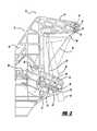
- FIG. 2is a partial side elevational view of the compact adjustable pedal assembly of FIG. 1 in an adjusted position and a non-adjusted position, according to the present invention.
- FIG. 3is an enlarged side view of the first pivot point of FIG. 1 , according to the present invention.
- FIG. 4is a side view of an alternative embodiment of the pedal assembly of FIG. 1 , according to the present invention.
- a compact pedal assembly 10for transferring a signal between a vehicle operator or driver (not shown) and an actuating mechanism (not shown) to control the movement of the vehicle, is illustrated.
- the pedal assembly 10is an adjustable pedal assembly 10 .
- the pedal assembly 10is shown in a non-adjusted position, whereas in FIG. 2 the pedal assembly 10 is shown moving between a non-adjusted position and an adjusted position.
- the pedal assembly 10includes a mounting bracket 12 , or mounting base for attaching the pedal assembly 10 to a portion of the vehicle.
- the mounting bracket 12is attached to the dash panel (not shown).
- the mounting bracket 12includes a generally planar mounting face 13 .
- the mounting face 13includes at least one aperture for attaching the mounting bracket 12 to the vehicle using an attaching means, such as by bolting or the like.
- the mounting bracket 12also includes an upper arm 14 or a pair of opposed upper arms 14 extending radially from an uppermost end of the mounting face 13 .
- the upper armoperatively supports a swing plate in a manner to be described.
- the mounting bracket upper arm 14includes an aperture 16 located at an outermost end of the upper bracket arm at a first pivot axis shown at 18 .
- the upper arm aperture 16is round in shape, and pivotally supports a pivot pin 20 and an adjustable swing plate, in a manner to be described.
- the mounting bracket 12also includes a lower arm 22 extending radially from the mounting face 13 .
- the lower arm 22extends radially from a lower portion of the mounting bracket 12 .
- the lower arm 22is positioned below the upper arm 14 .
- the lower arm 22includes a substantially horizontally oriented slot 24 .
- the lower arm slot 24is inclined in a downwardly direction, with an upper edge of the slot located adjacent the mounting face 12 and a lower edge of the slot located below the upper edge of the slot 24 and an outer edge of the lower arm 22 .
- the mounting bracket 12generally has an “F” shape.
- a guide pin for the adjustment meansis adjustably displaceable within the lower arm inclined slot, in a manner to be described.
- the pedal assembly 10also includes a swing plate 26 .
- the swing plate 26includes a generally planar mounting face 28 , and an upper arm 30 extending radially from an upper edge of the swing plate mounting face 28 in an outward direction.
- An outermost end of the swing plate upper arm 30includes a slot 32 for receiving a pivot pin for pivotally supporting the swing plate by the mounting bracket upper arm 14 at the first pivot axis 18 .
- the swing plate slot 32is oval and has a substantially vertical orientation. Further, the slot has a length of about 1-2 mm. The swing plate slot 32 provides for a predetermined degree of freedom of movement of the swing plate 26 relative to the mounting bracket 12 during adjustment.
- the swing plate 26is pivotally and slidably attached between the mounting bracket upper arms 14 at a first pivot axis 18 using a conventionally known attaching means, such as pin 20 and clip or the like.
- the upper armincludes two finger-like projections, and the swing plate 26 is pivotally and slidably attached between the finger projections at the first pivot axis 18 , as previously described.
- the first pivot axis 18is fixed during pedal activation, and varies during pedal adjustment as the angular relationship between the swing plate 26 and bracket 12 varies during pedal adjustment due to movement of the swing plate with respect to the first pivot axis 18 .
- the swing plate 26also includes an attachment portion 34 for securing the swing plate to the adjustment mechanism in a manner to be described.
- the attachment portion 34 of the swing plate 26is a finger extending radially from a lower side edge of the swing plate mounting face 28 and directed towards the mounting bracket 12 , for securing the lower end of the swing plate to the adjustment mechanism.
- the attachment portion 34 of the swing plate 26is slidingly connected to the adjustment mechanism through the slot 24 in the mounting bracket lower arm 22 at a second, non-fixed attachment axis as shown at 36 . It should be appreciated that in this example the second, non-fixed attachment axis 36 is positioned below, and radially inward, from the first pivot axis 18 located in the mounting bracket upper arm 14 .
- the swing plate 26also includes a mounting face 28 for supporting a pedal arm assembly 38 .
- the pedal arm assembly 38includes an elongated pedal arm member 40 having an upper end and a lower end.
- the pedal arm assembly 38includes a pedal pad 42 secured to the lower end of the pedal arm member 40 .
- the pedal pad 42is a rectangular member made from an isomeric material, such as rubber.
- An upper portion of the pedal arm member 40is fixedly attached to the swing plate 26 . The fixed attachment of the pedal arm assembly to the swing plate 26 allows for pivotal movement of the pedal arm assembly 38 about a third pedal arm pivot axis shown at 44 during actuation of the pedal arm assembly 38 by an operator of the vehicle.
- the third pedal arm pivot axis 44is non-fixed during pedal adjustment as a result of the change in angular relationship between the mounting bracket 12 and the swing plate 26 during adjustment. Further, the third pedal arm pivot axis 44 is fixed during pedal operation. The third pedal arm pivot axis 44 is located between the first pivot axis 18 and second pivot axis 36 . The third pedal arm pivot axis 44 is displaced as the pedal assembly 10 is adjusted, but not as the pedal assembly 10 is actuated.
- the pedal arm assembly 38includes an electronic position sensing device 46 for electronic control of an associated component, such as the engine.
- the pedal assembly 10is an electronically controlled throttle assembly, as is known in the art.
- An example of an electronic position sensing device 46is a position sensor, potentiometer, inductive sensor, hall sensor or the like.
- the position sensing device 46is located at the third pedal arm pivot axis 44 , in order to detect the rotation of the pedal arm member 40 as a result of movement of the pedal pad 42 during actuation of the pedal arm assembly 38 by the operator. Movement of the pedal arm member 40 relative to the third pedal arm pivot axis 44 produces an electronic control signal proportional to the relative position of the pedal arm member 40 , to operate the corresponding control, which in this example is an engine control.
- the pedal arm assemblymay be attached to the swing plate as an integral unit.
- the pedal assembly 10further includes an adjustment mechanism 48 for adjusting the angular position of the swing plate 26 with respect to the mounting bracket 12 , in order to adjust the initial starting location of the pedal pad 26 .
- the adjustment mechanism 24includes a drive motor 50 secured to the mounting bracket 12 , for adjusting the relative location of the pedal arm member 40 between a nonadjusted position shown at 52 and a fully adjusted position shown at 54 or a position therebetween.
- the adjustment mechanism 48also includes a screw rod 56 . One end of the screw rod 56 is operatively attached to the drive motor, and the other end of the screw rod 56 is operatively attached to the swing plate attachment portion 34 .
- a radially extending pin 58interconnects the swing plate attachment portion 34 with the mounting bracket 12 at the second pivot axis 36 .
- the pin 58is slidingly disposed in the guide slot 24 in the mounting bracket lower arm 22 .
- the drive motor 50has a drive shaft with a worm gear portion, which engages a gear wheel with a threaded aperture to displace the screw rod 56 during adjustment.
- the drive motor 50may be connected to the drive shaft by a cable to drive the shaft.
- activation of the motor worm gearrotates the screw rod 56 to move the lower end of the swing plate 26 by displacing the screw rod 56 with respect to the guide slot 24 in the lower arm of the mounting bracket 12 , and thus varying the second pivot axis 36 .
- the pedal arm member 40is adjusted in a predetermined direction, such as forwardly or rearwardly, depending upon the direction of rotation of the screw rod 56 .
- the screw rod 56is located at one end of the guide slot 24 .
- the pin 58slides therethrough the guide slot 24 .
- the shape and position of the guide slot 24defines the travel of the swing plate 26 and the second pivot axis 36 .
- first pivot axis 18 in the upper end of the swing plate 26begins to vary eccentrically within the swing plate guide slot 32 .
- the upper end of the swing plate and first pivot axis 18moves in a downwardly and forwardly direction as the lower edge of the swing plate 26 and second pivot axis 36 moves rearwardly into the vehicle during pedal adjustment.
- the relative position of the pedal pad 52 with respect to the drivermoves along a predetermined path towards the driver. This unique combination of selectively adjustable pivot axis constrains the motion of the swing plate 26 with respect to the lower arm guide slot 24 in the mounting bracket 12 .
- the slot 32 in the upper end of the swing plate 26provides a predetermined degree of freedom of movement of the upper end of the swing plate 26 relative to the mounting bracket 12 . It also provides for a predetermined second degree of freedom of movement of the lower end of the swing plate 26 relative to the mounting bracket 12 .
- the first degree of freedomis less than the second degree of freedom.
- side loading of the screw rod 56 during adjustmentis reduced, as well as noise transmission through the screw rod and lower arm slot 24 .
- a material such as plasticmay be utilized in the worm gear. This may offer a cost or weight benefit.
- FIG. 4Another embodiment of a compact pedal assembly 110 is illustrated in FIG. 4 .
- the pedal assembly 110is illustrated in a fully adjusted position.
- the aperture 116 in the upper arm 114 of the mounting bracket 112is an elongated slot.
- the elongated slot 116has a generally vertical orientation.
- the slot 116may be inclined with an upper end of the slot 116 closer to the mounting bracket mounting face 113 than a lower end of the slot 116 .
- the compact pedal assembly 10operates in a manner similar to the previously described example.
- the first pivot axis 18 and upper end of the swing platemove upwardly as the second pivot axis 36 and lower end of the pedal arm move rearwardly into the vehicle.
- the lower arm slot 124 in the lower end of the mounting bracket 112has a horizontal orientation in this example, although other configurations are envisioned.
Landscapes
- Engineering & Computer Science (AREA)
- Physics & Mathematics (AREA)
- General Physics & Mathematics (AREA)
- Automation & Control Theory (AREA)
- Transportation (AREA)
- Mechanical Engineering (AREA)
- Manufacturing & Machinery (AREA)
- Chemical & Material Sciences (AREA)
- Combustion & Propulsion (AREA)
- Mechanical Control Devices (AREA)
- Auxiliary Drives, Propulsion Controls, And Safety Devices (AREA)
- Braking Elements And Transmission Devices (AREA)
Abstract
Description
Claims (10)
Priority Applications (7)
| Application Number | Priority Date | Filing Date | Title |
|---|---|---|---|
| US11/836,484US8069750B2 (en) | 2007-08-09 | 2007-08-09 | Compact pedal assembly with improved noise control |
| DE112008002125TDE112008002125A5 (en) | 2007-08-09 | 2008-08-07 | Compact pedal assembly with improved noise control |
| CN200880106203.1ACN101802744B (en) | 2007-08-09 | 2008-08-07 | Compact pedal assembly with improved noise control |
| BRPI0814148-7A2ABRPI0814148A2 (en) | 2007-08-09 | 2008-08-07 | SET COMPACT PEDAL FOR A VEHICLE |
| PCT/IB2008/002088WO2009019589A2 (en) | 2007-08-09 | 2008-08-07 | Compact pedal assembly with improved noise control |
| JP2010519539AJP5361081B2 (en) | 2007-08-09 | 2008-08-07 | Small pedal assembly with improved noise control |
| KR1020107004886AKR101471480B1 (en) | 2007-08-09 | 2008-08-07 | Compact pedal assembly with improved noise control |
Applications Claiming Priority (1)
| Application Number | Priority Date | Filing Date | Title |
|---|---|---|---|
| US11/836,484US8069750B2 (en) | 2007-08-09 | 2007-08-09 | Compact pedal assembly with improved noise control |
Publications (2)
| Publication Number | Publication Date |
|---|---|
| US20090038431A1 US20090038431A1 (en) | 2009-02-12 |
| US8069750B2true US8069750B2 (en) | 2011-12-06 |
Family
ID=40341827
Family Applications (1)
| Application Number | Title | Priority Date | Filing Date |
|---|---|---|---|
| US11/836,484Expired - Fee RelatedUS8069750B2 (en) | 2007-08-09 | 2007-08-09 | Compact pedal assembly with improved noise control |
Country Status (7)
| Country | Link |
|---|---|
| US (1) | US8069750B2 (en) |
| JP (1) | JP5361081B2 (en) |
| KR (1) | KR101471480B1 (en) |
| CN (1) | CN101802744B (en) |
| BR (1) | BRPI0814148A2 (en) |
| DE (1) | DE112008002125A5 (en) |
| WO (1) | WO2009019589A2 (en) |
Cited By (2)
| Publication number | Priority date | Publication date | Assignee | Title |
|---|---|---|---|---|
| US20100313699A1 (en)* | 2009-06-16 | 2010-12-16 | Shuichi Yoshida | Installation structure of a pedal stroke sensor |
| US20140331813A1 (en)* | 2013-05-07 | 2014-11-13 | Kia Motors Corp. | Active control method of pedal effort for accelerator |
Families Citing this family (13)
| Publication number | Priority date | Publication date | Assignee | Title |
|---|---|---|---|---|
| US7146876B2 (en)* | 2002-06-28 | 2006-12-12 | Ksr International Company | Adjustable pedal assembly |
| US7823480B2 (en)* | 2003-07-03 | 2010-11-02 | Ksr Technologies Co. | Support bracket with an integrated switch for a pedal assembly |
| JP6068751B2 (en) | 2013-11-01 | 2017-01-25 | 豊田鉄工株式会社 | Operation pedal device for vehicle |
| JP6267024B2 (en)* | 2014-03-17 | 2018-01-24 | 旭化成株式会社 | Brake bracket |
| US20170043662A1 (en)* | 2014-04-23 | 2017-02-16 | Daryl PERUSIC | Improvements in vehicle mounted pedal box assemblies |
| US11364800B2 (en) | 2018-08-30 | 2022-06-21 | Marine Acquisition (Us) Incorporated | Throttle pedal assembly |
| US11148646B2 (en)* | 2019-04-03 | 2021-10-19 | GM Global Technology Operations LLC | Retractable pedal assembly for a vehicle |
| US11157034B2 (en)* | 2019-09-30 | 2021-10-26 | Marine Acquisition (Us) Incorporated | Throttle pedal assembly |
| DE112020004912T5 (en)* | 2019-10-10 | 2022-08-04 | KSR IP Holdings, LLC | PEDAL ASSEMBLY FOR AUTONOMOUS VEHICLES |
| IT202000007639A1 (en)* | 2020-04-09 | 2021-10-09 | Plastic Components And Modules Automotive S P A | Pedal position adjustment mechanism |
| US11537159B2 (en) | 2020-04-09 | 2022-12-27 | Plastic Components And Modules Automotice S.P.A. | Pedal position adjusting mechanism |
| CN111731097A (en)* | 2020-07-06 | 2020-10-02 | 摩登汽车有限公司 | Automobile pedal assembly and automobile |
| KR20230028854A (en)* | 2021-08-23 | 2023-03-03 | 현대자동차주식회사 | Foldable pedal apparatus for vehicle |
Citations (115)
| Publication number | Priority date | Publication date | Assignee | Title |
|---|---|---|---|---|
| US2550732A (en) | 1946-08-23 | 1951-05-01 | American Steel Foundries | Brake arrangement and slack adjuster therefor |
| US2550731A (en) | 1946-06-22 | 1951-05-01 | American Steel Foundries | Brake adjusting means |
| US2860720A (en) | 1956-01-18 | 1958-11-18 | Gen Motors Corp | Adjustable toeboard for an automobile |
| US2860780A (en) | 1954-12-06 | 1958-11-18 | Kloeckner Humboldt Deutz Ag | Fuel injection valve |
| US2906842A (en) | 1958-03-20 | 1959-09-29 | Electro Snap Switch & Mfg Co | Adjustable actuator arm |
| US2908183A (en) | 1953-04-21 | 1959-10-13 | Giovanni Norman P Di | Accelerator foot control and adjustment mechanisms |
| US2936867A (en) | 1959-02-17 | 1960-05-17 | Nelson I Perry | Combined accelerator and foot brake |
| GB952831A (en) | 1960-01-15 | 1964-03-18 | Westland Aircraft Ltd | Improvements in or relating to adjustable pedal control means for vehicles |
| US3282125A (en) | 1963-12-23 | 1966-11-01 | Gen Motors Corp | Vehicle control pedals |
| US3301088A (en) | 1964-03-02 | 1967-01-31 | Gen Motors Corp | Vehicle adjustable control pedal assemblies |
| US3319487A (en) | 1964-01-09 | 1967-05-16 | Gen Motors Corp | Vehicle control pedals |
| US3338348A (en) | 1964-09-15 | 1967-08-29 | Gen Motors Corp | Brake pedal height adjusting and ratio changing mechanism |
| US3400607A (en) | 1965-12-20 | 1968-09-10 | Ford Motor Co | Vehicle control assembly |
| US3511109A (en) | 1968-10-14 | 1970-05-12 | Gen Motors Corp | Adjustable control pedals |
| US3563111A (en) | 1968-07-24 | 1971-02-16 | Gen Motors Corp | Adjustable control pedals |
| US3643525A (en) | 1970-05-26 | 1972-02-22 | Gen Motors Corp | Adjustable control pedals for vehicles |
| US3643524A (en) | 1970-05-26 | 1972-02-22 | Gen Motors Corp | Control pedals for vehicles |
| US3646831A (en) | 1970-07-06 | 1972-03-07 | Ford Motor Co | Variable ratio brake pedal |
| US3678779A (en) | 1970-11-12 | 1972-07-25 | Ford Motor Co | Variable ratio brake pedal |
| US3691868A (en) | 1971-07-06 | 1972-09-19 | Raymond P Smith | Adjustable pedal |
| US3754480A (en) | 1972-05-08 | 1973-08-28 | Gen Motors Corp | Vehicle control apparatus |
| US3765264A (en) | 1971-11-19 | 1973-10-16 | Grand Stamped Prod Co | Adjustable linkage |
| US3798995A (en) | 1972-11-09 | 1974-03-26 | H Schroter | Brake operating lever system |
| US3958677A (en) | 1974-09-18 | 1976-05-25 | Spanelis Evangelos L | Unitary pedal apparatus for selectively accelerating and braking a vehicle |
| US3975972A (en) | 1975-04-16 | 1976-08-24 | Muhleck Earl M | Adjustable pedal construction |
| US4386537A (en) | 1978-10-10 | 1983-06-07 | Clark Equipment Company | Variable ratio brake pedal |
| US4470570A (en) | 1982-09-29 | 1984-09-11 | The Boeing Company | Control assembly for aircraft |
| US4497399A (en) | 1982-12-03 | 1985-02-05 | General Motors Corporation | Adjusting mechanism for a manually operated clutch |
| US4528590A (en) | 1983-11-09 | 1985-07-09 | Allied Corporation | Electronic treadle |
| US4683977A (en) | 1985-05-15 | 1987-08-04 | Thomas Murphy | Adjustable pedal assembly |
| US4779481A (en) | 1987-04-16 | 1988-10-25 | J. I. Case Company | Adjustable two-pedal swing control apparatus |
| US4850094A (en) | 1988-01-26 | 1989-07-25 | Bomar Corporation | Method for mounting gate opener |
| US4870871A (en) | 1987-05-22 | 1989-10-03 | Wickes Manufacturing Company | Adjustable accelerator and brake pedal mechanism |
| US4875385A (en) | 1986-08-18 | 1989-10-24 | Sitrin Gabriel M | Control pedal apparatus for a motor vehicle |
| US4883037A (en) | 1988-02-17 | 1989-11-28 | Automotive Products Plc | Throttle control system |
| US4912997A (en) | 1989-06-02 | 1990-04-03 | Chrysler Corporation | Electric shift selector mechanism for transmission |
| US4915075A (en) | 1989-03-20 | 1990-04-10 | Caterpillar Inc. | Accelerator pedal position sensor |
| US4938304A (en) | 1987-09-14 | 1990-07-03 | Mazda Motor Corporation | Throttle valve control apparatus for a vehicle |
| US4958607A (en) | 1989-04-18 | 1990-09-25 | Williams Controls, Inc. | Foot pedal arrangement for electronic throttle control of truck engines |
| US4969437A (en) | 1988-07-23 | 1990-11-13 | Daimler-Benz Ag | Adjusting device for a control element, especially for the throttle flap of an internal combustion engine |
| US4986238A (en) | 1988-08-31 | 1991-01-22 | Aisin Seiki Kabushiki Kaisha | Throttle control system |
| US4989474A (en) | 1986-08-18 | 1991-02-05 | Brecom Corporation | Control pedal apparatus for a motor vehicle |
| US5010782A (en) | 1988-07-28 | 1991-04-30 | Fuji Kiko Company, Ltd. | Position adjustable pedal assembly |
| US5036576A (en) | 1988-06-06 | 1991-08-06 | Cherry Division Of Textron, Inc. | Method of installing a fastener |
| US5056742A (en) | 1987-11-13 | 1991-10-15 | The Boeing Company | Modular rudder pedal and brake control assembly for aircraft |
| US5063811A (en) | 1990-07-09 | 1991-11-12 | Ford Motor Company | Accelerator pedal assembly |
| US5078024A (en) | 1986-08-18 | 1992-01-07 | Comfort Pedals Inc. | Control pedal apparatus for a motor vehicle |
| US5086663A (en) | 1989-07-28 | 1992-02-11 | Fuji Kiko Company, Limited | Adjustable pedal |
| US5121889A (en) | 1991-05-06 | 1992-06-16 | Grumman Aerospace Corporation | Electronic foot controls |
| US5125483A (en) | 1990-11-13 | 1992-06-30 | Honda Giken Kogyo Kabushiki Kaisha | Motor vehicle brake system with fail-safe mechanism |
| US5172606A (en) | 1992-03-25 | 1992-12-22 | General Motors Corporation | Module cockpit/support structure with adjustable pedals |
| US5211072A (en) | 1990-07-26 | 1993-05-18 | Dura Mechanical Components, Inc. | Variable ratio park brake with slack adjust |
| US5215057A (en) | 1991-08-21 | 1993-06-01 | Hitachi, Ltd. | Electrically-operated throttle actuator |
| US5214834A (en) | 1990-05-18 | 1993-06-01 | S.A. Des Etablissments Staubli | Process for assembling the actuation elements of a rotating dobby |
| US5233882A (en) | 1990-07-12 | 1993-08-10 | General Motors Corporation | Remote control lever module |
| US5239886A (en) | 1992-08-03 | 1993-08-31 | Cincinnati Milacron Inc. | Stability high gain and dynamic stiffness servo axis drive system and method |
| US5241936A (en) | 1991-09-09 | 1993-09-07 | Williams Controls, Inc. | Foot pedal arrangement for electronic throttle control of truck engines |
| US5351573A (en) | 1991-10-07 | 1994-10-04 | Cicotte Edmond B | Adjustable automobile pedal system |
| US5385068A (en) | 1992-12-18 | 1995-01-31 | Cts Corporation | Electronic accelerator pedal assembly with pedal force sensor |
| US5408899A (en) | 1993-06-14 | 1995-04-25 | Brecom Subsidiary Corporation No. 1 | Foot pedal devices for controlling engines |
| EP0492873B1 (en) | 1990-12-28 | 1995-09-06 | Ford Motor Company Limited | Operating mechanism for hydraulic cylinders |
| US5460061A (en) | 1993-09-17 | 1995-10-24 | Comfort Pedals, Inc. | Adjustable control pedal apparatus |
| US5497677A (en) | 1993-12-21 | 1996-03-12 | Dr. Ing. H.C.F. Porsche Ag | Accelerator pedal device for a motor vehicle |
| FR2715485B1 (en) | 1994-01-26 | 1996-04-05 | Peugeot | Arrangement for mounting an accelerator pedal for a motor vehicle. |
| US5632183A (en) | 1995-08-09 | 1997-05-27 | Comfort Pedals, Inc. | Adjustable pedal assembly |
| DE3904616C2 (en) | 1988-02-22 | 1997-08-21 | Volkswagen Ag | Arrangement for storing at least one hanging pedal lever |
| FR2739947B1 (en) | 1995-10-17 | 1997-12-12 | Renault | MOTOR VEHICLE CRANKSET HAVING A DEVICE FOR ADJUSTING THE HEIGHT AND THE ORIENTATION OF THE PEDALS |
| US5697260A (en) | 1995-08-09 | 1997-12-16 | Teleflex Incorporated | Electronic adjustable pedal assembly |
| US5722302A (en) | 1995-08-09 | 1998-03-03 | Teleflex, Inc. | Adjustable pedal assembly |
| US5771752A (en) | 1991-10-07 | 1998-06-30 | Cicotte; Edmond B. | Adjustable automobile pedal system |
| US5819593A (en) | 1995-08-09 | 1998-10-13 | Comcorp Technologies, Inc. | Electronic adjustable pedal assembly |
| US5884532A (en) | 1997-04-28 | 1999-03-23 | Tecnology Holding Company Ii | Adjustable pedal apparatus |
| US5887488A (en) | 1997-04-16 | 1999-03-30 | Imo Industries, Inc. | Vehicular accelerator pedal apparatus |
| US5927154A (en) | 1998-02-11 | 1999-07-27 | General Motors Corporation | Adjustable brake and clutch pedals |
| US5996439A (en) | 1998-07-22 | 1999-12-07 | General Motors Corporation | Brake pedal mechanism |
| US5996438A (en) | 1998-06-23 | 1999-12-07 | General Motors Corporation | Adjustable accelerator pedal |
| US6019241A (en) | 1998-01-05 | 2000-02-01 | Burns; Kyle S. | Paint tray with storable carrying handle |
| US6019015A (en) | 1998-02-11 | 2000-02-01 | General Motors Corporation | Adjustable accelerator pedal |
| US6073515A (en) | 1998-07-21 | 2000-06-13 | General Motors Corporation | Adjustable foot support |
| US6109241A (en) | 1999-01-26 | 2000-08-29 | Teleflex Incorporated | Adjustable pedal assembly with electronic throttle control |
| US6151986A (en) | 1997-10-09 | 2000-11-28 | Ksr Industrial Corporation | Adjustable vehicle control pedals |
| US6151985A (en) | 1999-04-01 | 2000-11-28 | Daimlerchrysler Corporation | Adjustable pedal apparatus |
| US6151984A (en) | 1997-11-21 | 2000-11-28 | Teleflex Incorporated | Adjustable pedal assembly |
| US6173625B1 (en) | 1999-12-14 | 2001-01-16 | Teleflex Incorporated | Adjustable multi-pedal assembly |
| US6178847B1 (en) | 1997-10-09 | 2001-01-30 | Ksr Industrial Corporation | Adjustable vehicle control pedals |
| US6212970B1 (en) | 1999-08-24 | 2001-04-10 | Teleflex Incorporated | Pedal assembly with adjustable pad |
| US6289763B1 (en) | 1995-08-09 | 2001-09-18 | Teleflex Incorporated | Electronic adjustable pedal assembly |
| US6289761B1 (en) | 2000-02-04 | 2001-09-18 | Dura Global Technologies, Inc. | Automatic adjustable brake, clutch and accelerator pedals |
| US6321617B1 (en) | 2000-06-08 | 2001-11-27 | Jeffrey Schwyn | Adjustable pedal assembly |
| US6324939B1 (en) | 1999-02-14 | 2001-12-04 | Edmond B. Cicotte | Adjustable automobile pedal system |
| US20020002874A1 (en) | 2000-06-15 | 2002-01-10 | Pat Burton | Adjustable pedal assembly |
| US6364047B1 (en) | 2000-09-27 | 2002-04-02 | Teleflex Incorporated | Adjustable pedal assembly—floating floor |
| US20020038577A1 (en) | 2000-05-30 | 2002-04-04 | Richard Bialk | Pedalry and pedal system with a multiple of such pedalries |
| US6367348B1 (en) | 2000-05-01 | 2002-04-09 | Dura Global Technologies, Inc. | Adjustable brake, clutch and accelerator pedals |
| US6367349B1 (en) | 2000-05-01 | 2002-04-09 | Dura Global Technologies, Inc. | Adjustable brake, clutch and accelerator pedals |
| US6389927B1 (en) | 2000-07-12 | 2002-05-21 | Ksr International, Inc. | Adjustable control vehicle pedal |
| US20020088303A1 (en) | 2000-10-19 | 2002-07-11 | Takashi Hayashihara | Vehicle pedal device capable of adjusting pedal position in longitudinal direction of vehicle |
| US6431021B1 (en) | 1999-06-24 | 2002-08-13 | Atoma International Corp. | Adjustable pedal |
| US6450061B1 (en) | 1999-09-23 | 2002-09-17 | Delphi Technologies, Inc. | Adjustable pedal system with misalignment sensor |
| JP2002287837A (en) | 2001-03-23 | 2002-10-04 | Aisin Seiki Co Ltd | Pedal device |
| US6520045B2 (en) | 2000-04-04 | 2003-02-18 | Toyoda Iron Works Co., Ltd. | Vehicle pedal device assembly including two pedals whose non-operated positions are adjustable in vehicle longitudinal direction |
| US20030056615A1 (en) | 2000-04-07 | 2003-03-27 | Oberheide G. Clarke | Adjustable pedal mechanism for a motor vehicle |
| US20030084744A1 (en) | 2001-11-05 | 2003-05-08 | Parenteau Chantal S | Adjustable assembly |
| US6655231B2 (en) | 2001-02-21 | 2003-12-02 | Ksr Industrial Corporation | Pedal adjuster for electronic throttle control |
| US6662677B2 (en) | 1999-10-15 | 2003-12-16 | Teleflex Incorporated | Adjustable pedal assembly (banana rod) |
| US20040000211A1 (en)* | 2002-06-28 | 2004-01-01 | Willemsen Larry G. | Adjustable pedal assembly |
| US20040031350A1 (en) | 2000-10-07 | 2004-02-19 | Christopher Williams | Collapsible pedal box |
| US6722226B2 (en) | 2001-09-24 | 2004-04-20 | Daimlerchrysler Corporation | Adjustable pedal assembly |
| US6763741B2 (en) | 2001-05-30 | 2004-07-20 | Daimlerchrysler Ag | Adjustable foot-lever assembly |
| US20040217726A1 (en) | 2000-07-12 | 2004-11-04 | Willemsen Larry G. | Adjustable control vehicle pedal |
| US20060169549A1 (en)* | 1999-03-02 | 2006-08-03 | Lang Joseph A | Golf car having disk brakes and flexible brake lines |
| US20070137396A1 (en)* | 2005-10-31 | 2007-06-21 | Akhil Mahendra | Adjustable pedal system with low brake ratio change |
| JP4219562B2 (en) | 1999-04-13 | 2009-02-04 | セミトゥール・インコーポレイテッド | System for electrochemical processing of workpieces |
| US20090223319A1 (en)* | 2008-03-10 | 2009-09-10 | Sl Corporation | Adjustable pedal system |
| US20100107804A1 (en)* | 2008-11-04 | 2010-05-06 | Tervol Stuart A | Fixed pedal assembly with multi-piece support bracket and captive pivot |
Family Cites Families (7)
| Publication number | Priority date | Publication date | Assignee | Title |
|---|---|---|---|---|
| CA1289039C (en)* | 1986-08-18 | 1991-09-17 | Gabriel M. Sitrin | Control pedal apparatus for a motor vehicle |
| JP2001018679A (en)* | 1999-07-06 | 2001-01-23 | Toyota Motor Corp | Vehicle pedal system |
| CN2451805Y (en)* | 2000-11-22 | 2001-10-03 | 陈谦 | Energy-saving clutch |
| US7114411B2 (en)* | 2001-05-09 | 2006-10-03 | Ksr Industrial Corporation | Pedal adjuster |
| JP3931060B2 (en)* | 2001-08-08 | 2007-06-13 | Ntn株式会社 | Syringe pump lead screw and syringe pump |
| JP4778966B2 (en)* | 2004-07-06 | 2011-09-21 | ケイエスアール テクノロジーズ カンパニー | Support bracket with integrated switch for pedal assembly |
| KR100649166B1 (en)* | 2005-11-09 | 2006-11-27 | 에스엘 주식회사 | Adjustable pedal system |
- 2007
- 2007-08-09USUS11/836,484patent/US8069750B2/ennot_activeExpired - Fee Related
- 2008
- 2008-08-07CNCN200880106203.1Apatent/CN101802744B/ennot_activeExpired - Fee Related
- 2008-08-07WOPCT/IB2008/002088patent/WO2009019589A2/enactiveApplication Filing
- 2008-08-07JPJP2010519539Apatent/JP5361081B2/ennot_activeExpired - Fee Related
- 2008-08-07BRBRPI0814148-7A2Apatent/BRPI0814148A2/ennot_activeIP Right Cessation
- 2008-08-07KRKR1020107004886Apatent/KR101471480B1/ennot_activeExpired - Fee Related
- 2008-08-07DEDE112008002125Tpatent/DE112008002125A5/ennot_activeWithdrawn
Patent Citations (127)
| Publication number | Priority date | Publication date | Assignee | Title |
|---|---|---|---|---|
| US2550731A (en) | 1946-06-22 | 1951-05-01 | American Steel Foundries | Brake adjusting means |
| US2550732A (en) | 1946-08-23 | 1951-05-01 | American Steel Foundries | Brake arrangement and slack adjuster therefor |
| US2908183A (en) | 1953-04-21 | 1959-10-13 | Giovanni Norman P Di | Accelerator foot control and adjustment mechanisms |
| US2860780A (en) | 1954-12-06 | 1958-11-18 | Kloeckner Humboldt Deutz Ag | Fuel injection valve |
| US2860720A (en) | 1956-01-18 | 1958-11-18 | Gen Motors Corp | Adjustable toeboard for an automobile |
| US2906842A (en) | 1958-03-20 | 1959-09-29 | Electro Snap Switch & Mfg Co | Adjustable actuator arm |
| US2936867A (en) | 1959-02-17 | 1960-05-17 | Nelson I Perry | Combined accelerator and foot brake |
| GB952831A (en) | 1960-01-15 | 1964-03-18 | Westland Aircraft Ltd | Improvements in or relating to adjustable pedal control means for vehicles |
| US3282125A (en) | 1963-12-23 | 1966-11-01 | Gen Motors Corp | Vehicle control pedals |
| US3319487A (en) | 1964-01-09 | 1967-05-16 | Gen Motors Corp | Vehicle control pedals |
| US3301088A (en) | 1964-03-02 | 1967-01-31 | Gen Motors Corp | Vehicle adjustable control pedal assemblies |
| US3338348A (en) | 1964-09-15 | 1967-08-29 | Gen Motors Corp | Brake pedal height adjusting and ratio changing mechanism |
| US3400607A (en) | 1965-12-20 | 1968-09-10 | Ford Motor Co | Vehicle control assembly |
| US3563111A (en) | 1968-07-24 | 1971-02-16 | Gen Motors Corp | Adjustable control pedals |
| US3511109A (en) | 1968-10-14 | 1970-05-12 | Gen Motors Corp | Adjustable control pedals |
| US3643524A (en) | 1970-05-26 | 1972-02-22 | Gen Motors Corp | Control pedals for vehicles |
| US3643525A (en) | 1970-05-26 | 1972-02-22 | Gen Motors Corp | Adjustable control pedals for vehicles |
| US3646831A (en) | 1970-07-06 | 1972-03-07 | Ford Motor Co | Variable ratio brake pedal |
| US3678779A (en) | 1970-11-12 | 1972-07-25 | Ford Motor Co | Variable ratio brake pedal |
| US3691868A (en) | 1971-07-06 | 1972-09-19 | Raymond P Smith | Adjustable pedal |
| US3765264A (en) | 1971-11-19 | 1973-10-16 | Grand Stamped Prod Co | Adjustable linkage |
| US3754480A (en) | 1972-05-08 | 1973-08-28 | Gen Motors Corp | Vehicle control apparatus |
| US3798995A (en) | 1972-11-09 | 1974-03-26 | H Schroter | Brake operating lever system |
| US3958677A (en) | 1974-09-18 | 1976-05-25 | Spanelis Evangelos L | Unitary pedal apparatus for selectively accelerating and braking a vehicle |
| US3975972A (en) | 1975-04-16 | 1976-08-24 | Muhleck Earl M | Adjustable pedal construction |
| US4386537A (en) | 1978-10-10 | 1983-06-07 | Clark Equipment Company | Variable ratio brake pedal |
| US4470570A (en) | 1982-09-29 | 1984-09-11 | The Boeing Company | Control assembly for aircraft |
| US4497399A (en) | 1982-12-03 | 1985-02-05 | General Motors Corporation | Adjusting mechanism for a manually operated clutch |
| US4528590A (en) | 1983-11-09 | 1985-07-09 | Allied Corporation | Electronic treadle |
| US4683977A (en) | 1985-05-15 | 1987-08-04 | Thomas Murphy | Adjustable pedal assembly |
| US4989474A (en) | 1986-08-18 | 1991-02-05 | Brecom Corporation | Control pedal apparatus for a motor vehicle |
| US5078024A (en) | 1986-08-18 | 1992-01-07 | Comfort Pedals Inc. | Control pedal apparatus for a motor vehicle |
| US4875385A (en) | 1986-08-18 | 1989-10-24 | Sitrin Gabriel M | Control pedal apparatus for a motor vehicle |
| US4779481A (en) | 1987-04-16 | 1988-10-25 | J. I. Case Company | Adjustable two-pedal swing control apparatus |
| US4870871A (en) | 1987-05-22 | 1989-10-03 | Wickes Manufacturing Company | Adjustable accelerator and brake pedal mechanism |
| US4938304A (en) | 1987-09-14 | 1990-07-03 | Mazda Motor Corporation | Throttle valve control apparatus for a vehicle |
| US5056742A (en) | 1987-11-13 | 1991-10-15 | The Boeing Company | Modular rudder pedal and brake control assembly for aircraft |
| US4850094A (en) | 1988-01-26 | 1989-07-25 | Bomar Corporation | Method for mounting gate opener |
| US4883037A (en) | 1988-02-17 | 1989-11-28 | Automotive Products Plc | Throttle control system |
| DE3904616C2 (en) | 1988-02-22 | 1997-08-21 | Volkswagen Ag | Arrangement for storing at least one hanging pedal lever |
| US5036576A (en) | 1988-06-06 | 1991-08-06 | Cherry Division Of Textron, Inc. | Method of installing a fastener |
| US4969437A (en) | 1988-07-23 | 1990-11-13 | Daimler-Benz Ag | Adjusting device for a control element, especially for the throttle flap of an internal combustion engine |
| US5010782A (en) | 1988-07-28 | 1991-04-30 | Fuji Kiko Company, Ltd. | Position adjustable pedal assembly |
| US4986238A (en) | 1988-08-31 | 1991-01-22 | Aisin Seiki Kabushiki Kaisha | Throttle control system |
| US4915075A (en) | 1989-03-20 | 1990-04-10 | Caterpillar Inc. | Accelerator pedal position sensor |
| US4958607A (en) | 1989-04-18 | 1990-09-25 | Williams Controls, Inc. | Foot pedal arrangement for electronic throttle control of truck engines |
| US4912997A (en) | 1989-06-02 | 1990-04-03 | Chrysler Corporation | Electric shift selector mechanism for transmission |
| US5086663A (en) | 1989-07-28 | 1992-02-11 | Fuji Kiko Company, Limited | Adjustable pedal |
| US5214834A (en) | 1990-05-18 | 1993-06-01 | S.A. Des Etablissments Staubli | Process for assembling the actuation elements of a rotating dobby |
| US5063811A (en) | 1990-07-09 | 1991-11-12 | Ford Motor Company | Accelerator pedal assembly |
| US5233882A (en) | 1990-07-12 | 1993-08-10 | General Motors Corporation | Remote control lever module |
| US5211072A (en) | 1990-07-26 | 1993-05-18 | Dura Mechanical Components, Inc. | Variable ratio park brake with slack adjust |
| US5125483A (en) | 1990-11-13 | 1992-06-30 | Honda Giken Kogyo Kabushiki Kaisha | Motor vehicle brake system with fail-safe mechanism |
| EP0492873B1 (en) | 1990-12-28 | 1995-09-06 | Ford Motor Company Limited | Operating mechanism for hydraulic cylinders |
| US5121889A (en) | 1991-05-06 | 1992-06-16 | Grumman Aerospace Corporation | Electronic foot controls |
| US5215057A (en) | 1991-08-21 | 1993-06-01 | Hitachi, Ltd. | Electrically-operated throttle actuator |
| US5241936A (en) | 1991-09-09 | 1993-09-07 | Williams Controls, Inc. | Foot pedal arrangement for electronic throttle control of truck engines |
| US5351573A (en) | 1991-10-07 | 1994-10-04 | Cicotte Edmond B | Adjustable automobile pedal system |
| US5823064A (en) | 1991-10-07 | 1998-10-20 | Cicotte; Edmond B. | Adjustable automobile pedal system |
| US5771752A (en) | 1991-10-07 | 1998-06-30 | Cicotte; Edmond B. | Adjustable automobile pedal system |
| US5172606A (en) | 1992-03-25 | 1992-12-22 | General Motors Corporation | Module cockpit/support structure with adjustable pedals |
| US5239886A (en) | 1992-08-03 | 1993-08-31 | Cincinnati Milacron Inc. | Stability high gain and dynamic stiffness servo axis drive system and method |
| US5385068A (en) | 1992-12-18 | 1995-01-31 | Cts Corporation | Electronic accelerator pedal assembly with pedal force sensor |
| US5408899A (en) | 1993-06-14 | 1995-04-25 | Brecom Subsidiary Corporation No. 1 | Foot pedal devices for controlling engines |
| US5460061A (en) | 1993-09-17 | 1995-10-24 | Comfort Pedals, Inc. | Adjustable control pedal apparatus |
| US5497677A (en) | 1993-12-21 | 1996-03-12 | Dr. Ing. H.C.F. Porsche Ag | Accelerator pedal device for a motor vehicle |
| FR2715485B1 (en) | 1994-01-26 | 1996-04-05 | Peugeot | Arrangement for mounting an accelerator pedal for a motor vehicle. |
| US6289763B1 (en) | 1995-08-09 | 2001-09-18 | Teleflex Incorporated | Electronic adjustable pedal assembly |
| US5697260A (en) | 1995-08-09 | 1997-12-16 | Teleflex Incorporated | Electronic adjustable pedal assembly |
| US5722302A (en) | 1995-08-09 | 1998-03-03 | Teleflex, Inc. | Adjustable pedal assembly |
| US5632183A (en) | 1995-08-09 | 1997-05-27 | Comfort Pedals, Inc. | Adjustable pedal assembly |
| US5819593A (en) | 1995-08-09 | 1998-10-13 | Comcorp Technologies, Inc. | Electronic adjustable pedal assembly |
| US5937707A (en) | 1995-08-09 | 1999-08-17 | Technology Holding Company Ii | Vehicle pedal assembly including a hysteresis feedback device |
| FR2739947B1 (en) | 1995-10-17 | 1997-12-12 | Renault | MOTOR VEHICLE CRANKSET HAVING A DEVICE FOR ADJUSTING THE HEIGHT AND THE ORIENTATION OF THE PEDALS |
| US5887488A (en) | 1997-04-16 | 1999-03-30 | Imo Industries, Inc. | Vehicular accelerator pedal apparatus |
| US5884532A (en) | 1997-04-28 | 1999-03-23 | Tecnology Holding Company Ii | Adjustable pedal apparatus |
| US6178847B1 (en) | 1997-10-09 | 2001-01-30 | Ksr Industrial Corporation | Adjustable vehicle control pedals |
| US6151986A (en) | 1997-10-09 | 2000-11-28 | Ksr Industrial Corporation | Adjustable vehicle control pedals |
| US6453767B1 (en) | 1997-10-09 | 2002-09-24 | Ksr Industrial Corporation | Adjustable vehicle control pedals |
| US6305239B1 (en) | 1997-11-21 | 2001-10-23 | Teleflex Incorporated | Adjustable pedal assembly |
| US20020092374A1 (en) | 1997-11-21 | 2002-07-18 | Mattias Johansson | Adjustable pedal assembly |
| EP0918273B1 (en) | 1997-11-21 | 2004-07-21 | Teleflex Incorporated | Adjustable pedal assembly |
| SE518099C2 (en) | 1997-11-21 | 2002-08-27 | Claes Johansson Automotive Ab | Adjustable pedal rack for a vehicle |
| US6374695B1 (en) | 1997-11-21 | 2002-04-23 | Teleflex Incorporated | Adjustable pedal assembly |
| US6151984A (en) | 1997-11-21 | 2000-11-28 | Teleflex Incorporated | Adjustable pedal assembly |
| US6019241A (en) | 1998-01-05 | 2000-02-01 | Burns; Kyle S. | Paint tray with storable carrying handle |
| US6019015A (en) | 1998-02-11 | 2000-02-01 | General Motors Corporation | Adjustable accelerator pedal |
| US5927154A (en) | 1998-02-11 | 1999-07-27 | General Motors Corporation | Adjustable brake and clutch pedals |
| US5996438A (en) | 1998-06-23 | 1999-12-07 | General Motors Corporation | Adjustable accelerator pedal |
| US6073515A (en) | 1998-07-21 | 2000-06-13 | General Motors Corporation | Adjustable foot support |
| US5996439A (en) | 1998-07-22 | 1999-12-07 | General Motors Corporation | Brake pedal mechanism |
| US6237565B1 (en) | 1999-01-26 | 2001-05-29 | Teleflex Incorporated | Adjustable pedal assembly with electronic throttle control |
| US6109241A (en) | 1999-01-26 | 2000-08-29 | Teleflex Incorporated | Adjustable pedal assembly with electronic throttle control |
| US6324939B1 (en) | 1999-02-14 | 2001-12-04 | Edmond B. Cicotte | Adjustable automobile pedal system |
| US20060169549A1 (en)* | 1999-03-02 | 2006-08-03 | Lang Joseph A | Golf car having disk brakes and flexible brake lines |
| US6151985A (en) | 1999-04-01 | 2000-11-28 | Daimlerchrysler Corporation | Adjustable pedal apparatus |
| JP4219562B2 (en) | 1999-04-13 | 2009-02-04 | セミトゥール・インコーポレイテッド | System for electrochemical processing of workpieces |
| US6431021B1 (en) | 1999-06-24 | 2002-08-13 | Atoma International Corp. | Adjustable pedal |
| US6212970B1 (en) | 1999-08-24 | 2001-04-10 | Teleflex Incorporated | Pedal assembly with adjustable pad |
| US6450061B1 (en) | 1999-09-23 | 2002-09-17 | Delphi Technologies, Inc. | Adjustable pedal system with misalignment sensor |
| US6662677B2 (en) | 1999-10-15 | 2003-12-16 | Teleflex Incorporated | Adjustable pedal assembly (banana rod) |
| US6173625B1 (en) | 1999-12-14 | 2001-01-16 | Teleflex Incorporated | Adjustable multi-pedal assembly |
| US6289761B1 (en) | 2000-02-04 | 2001-09-18 | Dura Global Technologies, Inc. | Automatic adjustable brake, clutch and accelerator pedals |
| US6520045B2 (en) | 2000-04-04 | 2003-02-18 | Toyoda Iron Works Co., Ltd. | Vehicle pedal device assembly including two pedals whose non-operated positions are adjustable in vehicle longitudinal direction |
| US20030056615A1 (en) | 2000-04-07 | 2003-03-27 | Oberheide G. Clarke | Adjustable pedal mechanism for a motor vehicle |
| US6367349B1 (en) | 2000-05-01 | 2002-04-09 | Dura Global Technologies, Inc. | Adjustable brake, clutch and accelerator pedals |
| US6367348B1 (en) | 2000-05-01 | 2002-04-09 | Dura Global Technologies, Inc. | Adjustable brake, clutch and accelerator pedals |
| US20020038577A1 (en) | 2000-05-30 | 2002-04-04 | Richard Bialk | Pedalry and pedal system with a multiple of such pedalries |
| US6321617B1 (en) | 2000-06-08 | 2001-11-27 | Jeffrey Schwyn | Adjustable pedal assembly |
| US6584871B2 (en) | 2000-06-15 | 2003-07-01 | Ksr International, Inc. | Adjustable pedal assembly |
| US20020002874A1 (en) | 2000-06-15 | 2002-01-10 | Pat Burton | Adjustable pedal assembly |
| US7353729B2 (en)* | 2000-07-12 | 2008-04-08 | Ksr Technologies Co. | Adjustable control vehicle pedal |
| US6389927B1 (en) | 2000-07-12 | 2002-05-21 | Ksr International, Inc. | Adjustable control vehicle pedal |
| US20040217726A1 (en) | 2000-07-12 | 2004-11-04 | Willemsen Larry G. | Adjustable control vehicle pedal |
| US6364047B1 (en) | 2000-09-27 | 2002-04-02 | Teleflex Incorporated | Adjustable pedal assembly—floating floor |
| US20040031350A1 (en) | 2000-10-07 | 2004-02-19 | Christopher Williams | Collapsible pedal box |
| US20020088303A1 (en) | 2000-10-19 | 2002-07-11 | Takashi Hayashihara | Vehicle pedal device capable of adjusting pedal position in longitudinal direction of vehicle |
| US6655231B2 (en) | 2001-02-21 | 2003-12-02 | Ksr Industrial Corporation | Pedal adjuster for electronic throttle control |
| JP2002287837A (en) | 2001-03-23 | 2002-10-04 | Aisin Seiki Co Ltd | Pedal device |
| US6763741B2 (en) | 2001-05-30 | 2004-07-20 | Daimlerchrysler Ag | Adjustable foot-lever assembly |
| US6722226B2 (en) | 2001-09-24 | 2004-04-20 | Daimlerchrysler Corporation | Adjustable pedal assembly |
| US20030084744A1 (en) | 2001-11-05 | 2003-05-08 | Parenteau Chantal S | Adjustable assembly |
| US20040000211A1 (en)* | 2002-06-28 | 2004-01-01 | Willemsen Larry G. | Adjustable pedal assembly |
| US7146876B2 (en) | 2002-06-28 | 2006-12-12 | Ksr International Company | Adjustable pedal assembly |
| US20070137396A1 (en)* | 2005-10-31 | 2007-06-21 | Akhil Mahendra | Adjustable pedal system with low brake ratio change |
| US20090223319A1 (en)* | 2008-03-10 | 2009-09-10 | Sl Corporation | Adjustable pedal system |
| US20100107804A1 (en)* | 2008-11-04 | 2010-05-06 | Tervol Stuart A | Fixed pedal assembly with multi-piece support bracket and captive pivot |
Cited By (4)
| Publication number | Priority date | Publication date | Assignee | Title |
|---|---|---|---|---|
| US20100313699A1 (en)* | 2009-06-16 | 2010-12-16 | Shuichi Yoshida | Installation structure of a pedal stroke sensor |
| US8596163B2 (en)* | 2009-06-16 | 2013-12-03 | Mitsubishi Jidosha Kogyo Kabushiki Kaisha | Installation structure of a pedal stroke sensor |
| US20140331813A1 (en)* | 2013-05-07 | 2014-11-13 | Kia Motors Corp. | Active control method of pedal effort for accelerator |
| US9128509B2 (en)* | 2013-05-07 | 2015-09-08 | Hyundai Motor Company | Active control method of pedal effort for accelerator |
Also Published As
| Publication number | Publication date |
|---|---|
| WO2009019589A2 (en) | 2009-02-12 |
| CN101802744B (en) | 2013-05-08 |
| DE112008002125T5 (en) | 2010-10-14 |
| KR101471480B1 (en) | 2014-12-10 |
| JP5361081B2 (en) | 2013-12-04 |
| KR20100049099A (en) | 2010-05-11 |
| JP2010536083A (en) | 2010-11-25 |
| BRPI0814148A2 (en) | 2015-02-03 |
| US20090038431A1 (en) | 2009-02-12 |
| WO2009019589A3 (en) | 2009-04-02 |
| CN101802744A (en) | 2010-08-11 |
| DE112008002125A5 (en) | 2011-09-22 |
Similar Documents
| Publication | Publication Date | Title |
|---|---|---|
| US8069750B2 (en) | Compact pedal assembly with improved noise control | |
| US7963189B2 (en) | Adjustable pedal assembly | |
| JP3450245B2 (en) | Adjustable pedal body with electronic throttle control | |
| US6840130B2 (en) | Adjustable brake, clutch and accelerator pedals | |
| EP0410815A1 (en) | Adjustable pedal | |
| US7954398B2 (en) | Pedal device | |
| US6389927B1 (en) | Adjustable control vehicle pedal | |
| KR100395738B1 (en) | Adjustable pedal-parallel screw and rod | |
| US6763741B2 (en) | Adjustable foot-lever assembly | |
| US20070266816A1 (en) | Adjustable pedal device | |
| US7832305B2 (en) | Adjustable pedal system with low brake ratio change | |
| JP3129609B2 (en) | Pedal depression stroke detection device | |
| US6655231B2 (en) | Pedal adjuster for electronic throttle control | |
| JP4874517B2 (en) | Adjustable vehicle pedal | |
| EP1280034A1 (en) | Device for adjusting the position of a pedal | |
| JP2005275636A (en) | Automotive pedal equipment | |
| AU2001293238A1 (en) | Adjustable control vehicle pedal | |
| SE502184C2 (en) | Pedal device for motor vehicles | |
| JP4234464B2 (en) | Front and rear adjustable pedal device for vehicles | |
| JP2003532575A (en) | Driving pedal module | |
| KR20060013613A (en) | Adjustable pedal system with slot-link mechanism | |
| JP2006048280A (en) | Adjustable pedal device having groove hole link mechanism |
Legal Events
| Date | Code | Title | Description |
|---|---|---|---|
| AS | Assignment | Owner name:KSR INTERNATIONAL CO., CANADA Free format text:ASSIGNMENT OF ASSIGNORS INTEREST;ASSIGNORS:WILLEMSEN, LARRY;O'NEILL, DAN;REEL/FRAME:019676/0762 Effective date:20070711 | |
| AS | Assignment | Owner name:KSR TECHNOLOGIES CO., CANADA Free format text:ASSIGNMENT OF ASSIGNORS INTEREST;ASSIGNOR:KSR INTERNATIONAL CO.;REEL/FRAME:020288/0479 Effective date:20071130 | |
| ZAAA | Notice of allowance and fees due | Free format text:ORIGINAL CODE: NOA | |
| ZAAB | Notice of allowance mailed | Free format text:ORIGINAL CODE: MN/=. | |
| STCF | Information on status: patent grant | Free format text:PATENTED CASE | |
| AS | Assignment | Owner name:KSR IP HOLDINGS LLC., DELAWARE Free format text:ASSIGNMENT OF ASSIGNORS INTEREST;ASSIGNOR:KSR TECHNOLOGIES CO.;REEL/FRAME:032660/0691 Effective date:20140407 | |
| FPAY | Fee payment | Year of fee payment:4 | |
| AS | Assignment | Owner name:WELLS FARGO BANK, NATIONAL ASSOCIATION, TENNESSEE Free format text:PATENT COLLATERAL AGREEMENT;ASSIGNOR:KSR IP HOLDINGS LLC;REEL/FRAME:045541/0171 Effective date:20171228 | |
| MAFP | Maintenance fee payment | Free format text:PAYMENT OF MAINTENANCE FEE, 8TH YEAR, LARGE ENTITY (ORIGINAL EVENT CODE: M1552); ENTITY STATUS OF PATENT OWNER: LARGE ENTITY Year of fee payment:8 | |
| AS | Assignment | Owner name:WELLS FARGO CAPITAL FINANCE CORPORATION CANADA, CANADA Free format text:SECURITY INTEREST;ASSIGNOR:KSR IP HOLDINGS LLC;REEL/FRAME:056097/0664 Effective date:20210429 Owner name:KSR IP HOLDINGS, LLC, MICHIGAN Free format text:RELEASE BY SECURED PARTY;ASSIGNOR:WELLS FARGO BANK, NATIONAL ASSOCIATION;REEL/FRAME:056097/0267 Effective date:20210428 | |
| FEPP | Fee payment procedure | Free format text:MAINTENANCE FEE REMINDER MAILED (ORIGINAL EVENT CODE: REM.); ENTITY STATUS OF PATENT OWNER: LARGE ENTITY | |
| LAPS | Lapse for failure to pay maintenance fees | Free format text:PATENT EXPIRED FOR FAILURE TO PAY MAINTENANCE FEES (ORIGINAL EVENT CODE: EXP.); ENTITY STATUS OF PATENT OWNER: LARGE ENTITY | |
| STCH | Information on status: patent discontinuation | Free format text:PATENT EXPIRED DUE TO NONPAYMENT OF MAINTENANCE FEES UNDER 37 CFR 1.362 | |
| FP | Lapsed due to failure to pay maintenance fee | Effective date:20231206 | |
| AS | Assignment | Owner name:KSR IP HOLDINGS LLC, MICHIGAN Free format text:RELEASE OF SECURITY INTEREST;ASSIGNOR:WELLS FARGO CAPITAL FINANCE CORPORATION CANADA;REEL/FRAME:071918/0562 Effective date:20250703 |