US8068905B2 - Method and apparatus for continuous electrode impedance monitoring - Google Patents
Method and apparatus for continuous electrode impedance monitoringDownload PDFInfo
- Publication number
- US8068905B2 US8068905B2US11/205,373US20537305AUS8068905B2US 8068905 B2US8068905 B2US 8068905B2US 20537305 AUS20537305 AUS 20537305AUS 8068905 B2US8068905 B2US 8068905B2
- Authority
- US
- United States
- Prior art keywords
- signal
- test
- output
- physiological
- impedance
- Prior art date
- Legal status (The legal status is an assumption and is not a legal conclusion. Google has not performed a legal analysis and makes no representation as to the accuracy of the status listed.)
- Expired - Fee Related, expires
Links
- 238000000034methodMethods0.000titleclaimsdescription15
- 238000012544monitoring processMethods0.000titledescription9
- 238000012360testing methodMethods0.000claimsabstractdescription51
- 238000001914filtrationMethods0.000claimsdescription7
- 230000003213activating effectEffects0.000claims2
- 239000013078crystalSubstances0.000abstractdescription3
- 230000008859changeEffects0.000description2
- 238000010586diagramMethods0.000description2
- 230000004048modificationEffects0.000description2
- 238000012986modificationMethods0.000description2
- 230000004044responseEffects0.000description2
- 238000005070samplingMethods0.000description2
- 238000010998test methodMethods0.000description1
- 238000012956testing procedureMethods0.000description1
- 230000001960triggered effectEffects0.000description1
Images


Classifications
- A—HUMAN NECESSITIES
- A61—MEDICAL OR VETERINARY SCIENCE; HYGIENE
- A61B—DIAGNOSIS; SURGERY; IDENTIFICATION
- A61B5/00—Measuring for diagnostic purposes; Identification of persons
- A61B5/24—Detecting, measuring or recording bioelectric or biomagnetic signals of the body or parts thereof
- A—HUMAN NECESSITIES
- A61—MEDICAL OR VETERINARY SCIENCE; HYGIENE
- A61B—DIAGNOSIS; SURGERY; IDENTIFICATION
- A61B5/00—Measuring for diagnostic purposes; Identification of persons
- A61B5/24—Detecting, measuring or recording bioelectric or biomagnetic signals of the body or parts thereof
- A61B5/25—Bioelectric electrodes therefor
- A61B5/276—Protection against electrode failure
- A—HUMAN NECESSITIES
- A61—MEDICAL OR VETERINARY SCIENCE; HYGIENE
- A61B—DIAGNOSIS; SURGERY; IDENTIFICATION
- A61B5/00—Measuring for diagnostic purposes; Identification of persons
- A61B5/68—Arrangements of detecting, measuring or recording means, e.g. sensors, in relation to patient
- A61B5/6801—Arrangements of detecting, measuring or recording means, e.g. sensors, in relation to patient specially adapted to be attached to or worn on the body surface
- A61B5/6843—Monitoring or controlling sensor contact pressure
Definitions
- the present inventionrelates to a method and apparatus for ensuring the accuracy of an acquired physiological signal. More specifically, the present invention is a method of monitoring electrode impedance while receiving an electromagnetic physiological signal.
- Physiological monitorswill often have a testing procedure to check whether the interface between a sensor and the patient being monitored is adequate to acquire a physiological reading. This is especially true with regards to the acquisition of an electrophysiological signal.
- an electrophysiological signalis acquired through an electrode which is attached to the patient.
- the contact between an electrode and a patient's skincan significantly affect the results of an electrophysiological signal.
- High contact impedancegenerally causes poor quality recordings due to power interference.
- Electrophysiological signalssuch as EEG, ECG, EOG and EMG are often distorted by the test current utilized during the test. Consequently, the prior art devices have been unable to continuously monitor the contact impedance between the electrode and the patient.
- the present inventionis a method and apparatus for continuously monitoring a test signal while simultaneously acquiring a physiological signal.
- the impedance test methods currently employed in electrophysiological recording equipmentcause interference to the signal being recorded because the test signal has a frequency (or frequencies in the case of non-sinusoidal test waveforms) within the frequency band of the electrophysiological signal.
- a digital signal processorDSP
- a digital band pass filter of the DSPcan be used to extract the impedance test signal and electrode impedance from the received signal.
- the present inventionincludes a test signal generator capable of producing an impedance test signal comprising of a sine wave having a known frequency.
- the test signal generatorincludes a crystal oscillator, a counter, and a lookup table.
- the lookup table outputis applied to a digital to analog converter and is then low pass filtered using a conventional analog filter to produce a test signal comprised of a sine wave having a known frequency and voltage amplitude.
- the test signalis passed through the electrode and combines with an electrophysiological signal to form a combined signal.
- a signal processoris used to isolate the combined signal into the test signal component and the electrophysiological component.
- the signal processordigitally low pass filters the combined signal and the output of the low pass filter is the electrophysiological signal.
- the signal processorthen digitally bandpass filters the combined signal using a filter with a center frequency which is the same as the test frequency. The output of this filter is then used to calculate the electrode impedance.
- the present inventioncan be adapted to be integrated into an electrophysological monitoring system such as EEG, EOG, EMG, and ECG.
- EEGelectrophysological monitoring system
- EOGelectrophysological monitoring system
- EMGelectrophysological monitoring system
- ECGelectrophysiological monitoring system
- the contact impedance between an electrode and a patientcan be continuously monitored while simultaneously acquiring an electrophysiological signal.
- a displaycan be used to monitor both the physiological signal and the contact impedance.
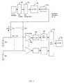
- FIG. 1is a block diagram of one embodiment of the present invention.
- FIG. 2is a graph of the relationship between a test frequency and a frequency of an electrophysiological signal.
- FIG. 3is a block diagram of a system employing one embodiment of the present invention.
- FIG. 4is an embodiment of a display in one embodiment of the present invention.
- the present inventionis a method and apparatus for change in electrode impedance monitoring via a combined test and physiological signal. While the embodiment disclosed is particularly adapted to monitor contact impedance and EEG, ECG, EOG, or EMG signals, one skilled in the art can readily adapt the present invention to monitor different parameters, which involve the testing of a sensor that is acquiring a physiological signal.
- the present inventionincludes a test signal generator capable of producing an impedance test signal comprising of a sine wave having a known frequency, fz 3 , which is slightly higher than the frequency range of the electrophysiological signal being monitored.
- a crystal oscillator 12provides a known, frequency stable signal to clock the input of a counter 14 .
- the counter outputsequentially accesses a lookup table 16 which can be implemented using any digital storage device such as an EPROM or RAM, containing a sine waveform in digital format.
- the lookup table 16 outputis then applied to a digital to analog converter (DAC) 18 .
- the output of the DACis low pass filtered using a conventional analog filter 20 to produce a sine wave of frequency, fz, and voltage amplitude Vz.
- a resistor, Rd 1with a resistance many times higher than the desired electrode impedance range, converts Vz into a test current Ie 1 .
- This currentflows through the electrode, represented in FIG. 1 by Ze 1 , to produce a voltage, Ve 1 , at the input of amplifier 22 .
- Vs 1there will also be an electrophysiological signal, Vs 1 , at the input of amplifier 22 .
- the combined signal of Ve 1 +Vs 1is amplified and then low pass filtered by anti-aliasing filter 24 before being converted into a digital signal by analog to digital converter (ADC) 26 .
- ADCanalog to digital converter
- the resultant digital signalis read by a digital signal processor (DSP) 30 via multiplexor 28 .
- FIG. 1shows the concept of the present invention extended to n electrode channels, using a separate ADC 26 for each channel, but a single ADC with an analog multiplexor would work equally well.
- the ADC sampling frequencyshould be greater than twice fz to prevent aliasing.
- the DSP 30should have sufficient computational power to execute both filters for all channels at the desired sample rate plus any storage or display functions. It should be noted that the DSP 30 could alter the sampling frequency, fs, signal bandwidth, fo, and impedance test frequency, fz, provided the relationship to each other is maintained as per FIG. 2 .
- the combined signalcan be isolated into the test signal component and the electrophysiological component by filtering the combined signal at appropriate frequencies.
- the DSP 30digitally low pass filters the combined signal using a filter with a ⁇ 3 dB point, fo, which is lower than the impedance test frequency, fz as shown in FIG. 2 .
- the physiological signal, Vs 1alone is the output of the low pass filter.
- the low pass filtershould have a sharp roll-off characteristic so that the test signal component at fz is completely removed.
- the filtershould also have a linear phase characteristic so the physiological signal is not distorted.
- a symmetrical FIR filterfinite impulse response
- the DSP 30also digitally bandpass filters the combined signal using a filter with a center frequency of fz, the same as the test frequency.
- the output of this filteris Ve 1 , as the physiological signal and any higher frequency noise has been removed by the bandpass filter.
- the bandpass filtermay be implemented as either an FIR or an IIR (infinite impulse response) if shorter computation time is needed.
- the impedance of each electrodecould be displayed numerically on a computer monitor connected to the DSP ( FIGS. 3 and 4 ) or used to activate indicators such as light emitting diodes attached to the amplifier circuit enclosure should the impedance exceed a pre-determined threshold.
- the present inventioncan be adapted to be integrated into an electrophysiological monitoring system 30 such as EEG, EOG, EMG, and ECG.
- EEGelectrophysiological monitoring system
- EOGelectronic glycol
- EMGelectrophysiological monitoring system
- ECGelectrophysiological monitoring system
- a display 32can be used to monitor both the physiological signal and the contact impedance.
- the electrophysiological monitor system 30may also communicate with a central monitoring station 34 .
- the electrophysiological monitor system 30is adapted to trigger an alarm condition at the central monitoring station 34 should the impedance of any of the electrodes exceed a pre-determined threshold for a pre-determined time (to avoid spurious values triggering the alarm).
- the operatorcould set the alarm threshold and the minimum time the threshold needs to be exceeded before the alarm is triggered via a computer network connection to the electrophysiological monitor system 30 . This would allow an operator to monitor the contact impedance of each electrode for each patient at a central location remote from the electrophysiological monitor system 30 .
Landscapes
- Life Sciences & Earth Sciences (AREA)
- Health & Medical Sciences (AREA)
- Medical Informatics (AREA)
- Biophysics (AREA)
- Pathology (AREA)
- Engineering & Computer Science (AREA)
- Biomedical Technology (AREA)
- Heart & Thoracic Surgery (AREA)
- Physics & Mathematics (AREA)
- Molecular Biology (AREA)
- Surgery (AREA)
- Animal Behavior & Ethology (AREA)
- General Health & Medical Sciences (AREA)
- Public Health (AREA)
- Veterinary Medicine (AREA)
- Measurement And Recording Of Electrical Phenomena And Electrical Characteristics Of The Living Body (AREA)
Abstract
Description
Claims (8)
Priority Applications (1)
| Application Number | Priority Date | Filing Date | Title |
|---|---|---|---|
| US11/205,373US8068905B2 (en) | 2004-02-26 | 2005-08-17 | Method and apparatus for continuous electrode impedance monitoring |
Applications Claiming Priority (3)
| Application Number | Priority Date | Filing Date | Title |
|---|---|---|---|
| PCT/US2004/006272WO2004075738A2 (en) | 2003-02-26 | 2004-02-26 | Method and apparatus for continuous electrode impedance monitoring |
| WOPCT/US04/06272 | 2004-02-26 | ||
| US11/205,373US8068905B2 (en) | 2004-02-26 | 2005-08-17 | Method and apparatus for continuous electrode impedance monitoring |
Publications (2)
| Publication Number | Publication Date |
|---|---|
| US20060020218A1 US20060020218A1 (en) | 2006-01-26 |
| US8068905B2true US8068905B2 (en) | 2011-11-29 |
Family
ID=35658228
Family Applications (1)
| Application Number | Title | Priority Date | Filing Date |
|---|---|---|---|
| US11/205,373Expired - Fee RelatedUS8068905B2 (en) | 2004-02-26 | 2005-08-17 | Method and apparatus for continuous electrode impedance monitoring |
Country Status (1)
| Country | Link |
|---|---|
| US (1) | US8068905B2 (en) |
Cited By (11)
| Publication number | Priority date | Publication date | Assignee | Title |
|---|---|---|---|---|
| US20110066053A1 (en)* | 2009-09-14 | 2011-03-17 | Imec | Adaptive sampling |
| US20110066054A1 (en)* | 2009-09-14 | 2011-03-17 | Imec | Method and electronic medical device for simultaneously measuring an impedance and a biopotential signal |
| US20110092834A1 (en)* | 2009-09-14 | 2011-04-21 | Imec | Analogue signal processors |
| US20140247058A1 (en)* | 2013-03-04 | 2014-09-04 | Mortara Instrument, Inc. | Impedance measurement system |
| US20150241505A1 (en)* | 2012-08-01 | 2015-08-27 | Draeger Medical Systems, Inc. | System And Method For Measuring Contact Impedance Of An Electrode |
| WO2016064456A1 (en)* | 2014-10-22 | 2016-04-28 | Natus Medical Incorporated | Simultaneous impedance testing method and apparatus |
| US10080898B2 (en) | 2015-05-29 | 2018-09-25 | Medtronic, Inc. | Simultaneous physiological sensing and stimulation with saturation detection |
| US10342451B2 (en) | 2013-10-23 | 2019-07-09 | Brain Sentinel, Inc. | Method and apparatus for detecting seizures including loose electrode monitoring |
| US10368805B2 (en) | 2016-12-29 | 2019-08-06 | Drägerwerk AG & Co. KGaA | Electrode impedance measurement |
| US10434308B2 (en) | 2015-05-29 | 2019-10-08 | Medtronic, Inc. | Impedance matching and electrode conditioning in patient interface systems |
| US11399762B1 (en) | 2021-08-05 | 2022-08-02 | Starcat LLC | Modular electroencephalograph (EEG) system |
Families Citing this family (44)
| Publication number | Priority date | Publication date | Assignee | Title |
|---|---|---|---|---|
| EP1816956A4 (en)* | 2004-11-24 | 2010-04-07 | Measurement Ltd | Two wire oscillator system for determining body impedance |
| US7630763B2 (en) | 2005-04-20 | 2009-12-08 | Cardiac Pacemakers, Inc. | Thoracic or intracardiac impedance detection with automatic vector selection |
| US20060271121A1 (en)* | 2005-05-25 | 2006-11-30 | Cardiac Pacemakers, Inc. | Closed loop impedance-based cardiac resynchronization therapy systems, devices, and methods |
| US8494618B2 (en)* | 2005-08-22 | 2013-07-23 | Cardiac Pacemakers, Inc. | Intracardiac impedance and its applications |
| US9839781B2 (en) | 2005-08-22 | 2017-12-12 | Cardiac Pacemakers, Inc. | Intracardiac impedance and its applications |
| US7974691B2 (en)* | 2005-09-21 | 2011-07-05 | Cardiac Pacemakers, Inc. | Method and apparatus for controlling cardiac resynchronization therapy using cardiac impedance |
| DE502007005697D1 (en)* | 2006-09-07 | 2010-12-30 | Telozo Gmbh | METHOD FOR DISTRIBUTING AND EVALUATING HEART CIRCULATION INFORMATION FROM CARDIOVASCULAR CURVES, ESPECIALLY FOR TELEMEDICAL APPLICATIONS |
| US9554721B1 (en)* | 2007-04-23 | 2017-01-31 | Neurowave Systems Inc. | Seizure detector, brain dysfunction monitor and method |
| WO2009023488A1 (en)* | 2007-08-10 | 2009-02-19 | Consolidated Research, Inc. | Apparatus and method for high-speed determination of bioelectric electrode impedances |
| WO2009036316A1 (en)* | 2007-09-14 | 2009-03-19 | Corventis, Inc. | Energy management, tracking and security for adherent patient monitor |
| US9186089B2 (en)* | 2007-09-14 | 2015-11-17 | Medtronic Monitoring, Inc. | Injectable physiological monitoring system |
| US20090076397A1 (en)* | 2007-09-14 | 2009-03-19 | Corventis, Inc. | Adherent Emergency Patient Monitor |
| WO2009036321A1 (en)* | 2007-09-14 | 2009-03-19 | Corventis, Inc. | Adherent device for cardiac rhythm management |
| US20090076342A1 (en)* | 2007-09-14 | 2009-03-19 | Corventis, Inc. | Adherent Multi-Sensor Device with Empathic Monitoring |
| EP3922171A1 (en) | 2007-09-14 | 2021-12-15 | Medtronic Monitoring, Inc. | Adherent cardiac monitor with advanced sensing capabilities |
| US20090076349A1 (en)* | 2007-09-14 | 2009-03-19 | Corventis, Inc. | Adherent Multi-Sensor Device with Implantable Device Communication Capabilities |
| WO2009036326A1 (en)* | 2007-09-14 | 2009-03-19 | Corventis, Inc. | Adherent athletic monitor |
| EP2194858B1 (en)* | 2007-09-14 | 2017-11-22 | Corventis, Inc. | Medical device automatic start-up upon contact to patient tissue |
| WO2009036327A1 (en) | 2007-09-14 | 2009-03-19 | Corventis, Inc. | Adherent device for respiratory monitoring and sleep disordered breathing |
| WO2009036369A1 (en)* | 2007-09-14 | 2009-03-19 | Corventis, Inc. | System and methods for wireless body fluid monitoring |
| US8116841B2 (en)* | 2007-09-14 | 2012-02-14 | Corventis, Inc. | Adherent device with multiple physiological sensors |
| US8343079B2 (en)* | 2007-10-18 | 2013-01-01 | Innovative Surgical Solutions, Llc | Neural monitoring sensor |
| US20090259137A1 (en)* | 2007-11-14 | 2009-10-15 | Emotiv Systems Pty Ltd | Determination of biosensor contact quality |
| EP2257216B1 (en)* | 2008-03-12 | 2021-04-28 | Medtronic Monitoring, Inc. | Heart failure decompensation prediction based on cardiac rhythm |
| WO2009146214A1 (en)* | 2008-04-18 | 2009-12-03 | Corventis, Inc. | Method and apparatus to measure bioelectric impedance of patient tissue |
| US20100191310A1 (en)* | 2008-07-29 | 2010-07-29 | Corventis, Inc. | Communication-Anchor Loop For Injectable Device |
| US8154435B2 (en)* | 2008-08-22 | 2012-04-10 | Microsoft Corporation | Stability monitoring using synthetic aperture radar |
| US10007758B2 (en) | 2009-03-04 | 2018-06-26 | Masimo Corporation | Medical monitoring system |
| US9323894B2 (en) | 2011-08-19 | 2016-04-26 | Masimo Corporation | Health care sanitation monitoring system |
| JP5749658B2 (en) | 2009-03-04 | 2015-07-15 | マシモ・コーポレイション | Medical monitoring system |
| US10032002B2 (en) | 2009-03-04 | 2018-07-24 | Masimo Corporation | Medical monitoring system |
| WO2011050283A2 (en) | 2009-10-22 | 2011-04-28 | Corventis, Inc. | Remote detection and monitoring of functional chronotropic incompetence |
| US9451897B2 (en)* | 2009-12-14 | 2016-09-27 | Medtronic Monitoring, Inc. | Body adherent patch with electronics for physiologic monitoring |
| US8965498B2 (en) | 2010-04-05 | 2015-02-24 | Corventis, Inc. | Method and apparatus for personalized physiologic parameters |
| US9980662B2 (en)* | 2010-05-25 | 2018-05-29 | Neurowave Systems Inc. | Method and system for electrode impedance measurement |
| US10357177B2 (en)* | 2013-12-13 | 2019-07-23 | General Electric Company | Systems and methods for electrical impedance imaging |
| US9615762B2 (en)* | 2014-12-11 | 2017-04-11 | General Electric Company | Coordinating interface for electrophysiology studies |
| KR102451268B1 (en) | 2015-12-09 | 2022-10-06 | 삼성전자주식회사 | Signal processing method, signal filtering apparatus and signal processing unit |
| CN105559773B (en)* | 2015-12-12 | 2018-11-27 | 中国计量学院 | It is exclusively used in the signal generator of medical exercise stress calibration |
| EP3372158B1 (en)* | 2017-03-08 | 2021-05-12 | Inomed Medizintechnik GmbH | System for intraoperative monitoring of the functionality of nerves |
| US10492704B2 (en)* | 2017-08-29 | 2019-12-03 | Biosense Webster (Israel) Ltd. | Medical patch for simultaneously sensing ECG signals and impedance-indicative electrical signals |
| JP7149613B2 (en)* | 2017-10-20 | 2022-10-07 | 株式会社Lifescapes | Rehabilitation support system, electroencephalogram measurement system control method, program, and non-temporary recording medium |
| US11779253B1 (en)* | 2019-10-28 | 2023-10-10 | Cognionics, Inc. | Measurement of electrode impedances in biopotential-physiological-phenomena sensing systems |
| TWI752867B (en)* | 2020-04-24 | 2022-01-11 | 聯發科技股份有限公司 | Circuitry of a biopotential acquisition system |
Citations (13)
| Publication number | Priority date | Publication date | Assignee | Title |
|---|---|---|---|---|
| US4459993A (en)* | 1982-08-20 | 1984-07-17 | Camino Laboratories | Continuity detector for heartbeat rate measuring system |
| US4610254A (en)* | 1984-03-08 | 1986-09-09 | Physio-Control Corporation | Interactive portable defibrillator |
| US4870341A (en)* | 1986-11-26 | 1989-09-26 | First Medical Devices Corporation | Impedance measurement circuit |
| US4919145A (en)* | 1988-07-13 | 1990-04-24 | Physio-Control Corporation | Method and apparatus for sensing lead and transthoracic impedances |
| US4993423A (en) | 1988-07-13 | 1991-02-19 | Physio-Control Corporation | Method and apparatus for differential lead impedance comparison |
| US5042498A (en) | 1990-04-06 | 1991-08-27 | Hewlett-Packard Company | Intelligent electrocardiogram system |
| US5184616A (en)* | 1991-10-21 | 1993-02-09 | Telectronics Pacing Systems, Inc. | Apparatus and method for generation of varying waveforms in arrhythmia control system |
| US5300093A (en)* | 1992-09-14 | 1994-04-05 | Telectronics Pacing Systems, Inc. | Apparatus and method for measuring, formatting and transmitting combined intracardiac impedance data and electrograms |
| US5819741A (en)* | 1994-10-07 | 1998-10-13 | Ortivus Medical Ab | Cardiac monitoring system and method |
| US6007532A (en) | 1997-08-29 | 1999-12-28 | 3M Innovative Properties Company | Method and apparatus for detecting loss of contact of biomedical electrodes with patient skin |
| US20020046756A1 (en)* | 2000-09-20 | 2002-04-25 | Laizzo Paul A. | System and method for determining tissue contact of an implantable medical device within a body |
| US6487449B1 (en)* | 2000-05-23 | 2002-11-26 | Ge Medical Systems Information Technologies, Inc. | Method and apparatus for reducing noise and detecting electrode faults in medical equipment |
| US7020513B2 (en)* | 2002-01-23 | 2006-03-28 | Ela Medical S.A. | Testing the electrical continuity of the connecting cables for a recorder of physiological signals, in particular a holter recorder of ECG signals |
- 2005
- 2005-08-17USUS11/205,373patent/US8068905B2/ennot_activeExpired - Fee Related
Patent Citations (13)
| Publication number | Priority date | Publication date | Assignee | Title |
|---|---|---|---|---|
| US4459993A (en)* | 1982-08-20 | 1984-07-17 | Camino Laboratories | Continuity detector for heartbeat rate measuring system |
| US4610254A (en)* | 1984-03-08 | 1986-09-09 | Physio-Control Corporation | Interactive portable defibrillator |
| US4870341A (en)* | 1986-11-26 | 1989-09-26 | First Medical Devices Corporation | Impedance measurement circuit |
| US4919145A (en)* | 1988-07-13 | 1990-04-24 | Physio-Control Corporation | Method and apparatus for sensing lead and transthoracic impedances |
| US4993423A (en) | 1988-07-13 | 1991-02-19 | Physio-Control Corporation | Method and apparatus for differential lead impedance comparison |
| US5042498A (en) | 1990-04-06 | 1991-08-27 | Hewlett-Packard Company | Intelligent electrocardiogram system |
| US5184616A (en)* | 1991-10-21 | 1993-02-09 | Telectronics Pacing Systems, Inc. | Apparatus and method for generation of varying waveforms in arrhythmia control system |
| US5300093A (en)* | 1992-09-14 | 1994-04-05 | Telectronics Pacing Systems, Inc. | Apparatus and method for measuring, formatting and transmitting combined intracardiac impedance data and electrograms |
| US5819741A (en)* | 1994-10-07 | 1998-10-13 | Ortivus Medical Ab | Cardiac monitoring system and method |
| US6007532A (en) | 1997-08-29 | 1999-12-28 | 3M Innovative Properties Company | Method and apparatus for detecting loss of contact of biomedical electrodes with patient skin |
| US6487449B1 (en)* | 2000-05-23 | 2002-11-26 | Ge Medical Systems Information Technologies, Inc. | Method and apparatus for reducing noise and detecting electrode faults in medical equipment |
| US20020046756A1 (en)* | 2000-09-20 | 2002-04-25 | Laizzo Paul A. | System and method for determining tissue contact of an implantable medical device within a body |
| US7020513B2 (en)* | 2002-01-23 | 2006-03-28 | Ela Medical S.A. | Testing the electrical continuity of the connecting cables for a recorder of physiological signals, in particular a holter recorder of ECG signals |
Cited By (20)
| Publication number | Priority date | Publication date | Assignee | Title |
|---|---|---|---|---|
| US8862210B2 (en) | 2009-09-14 | 2014-10-14 | Imec | Analogue signal processors |
| US20110066054A1 (en)* | 2009-09-14 | 2011-03-17 | Imec | Method and electronic medical device for simultaneously measuring an impedance and a biopotential signal |
| US20110092834A1 (en)* | 2009-09-14 | 2011-04-21 | Imec | Analogue signal processors |
| US8454505B2 (en)* | 2009-09-14 | 2013-06-04 | Imec | Method and electronic medical device for simultaneously measuring an impedance and a biopotential signal |
| US8755868B2 (en) | 2009-09-14 | 2014-06-17 | Imec | Adaptive sampling |
| US20110066053A1 (en)* | 2009-09-14 | 2011-03-17 | Imec | Adaptive sampling |
| US20150241505A1 (en)* | 2012-08-01 | 2015-08-27 | Draeger Medical Systems, Inc. | System And Method For Measuring Contact Impedance Of An Electrode |
| US20140247058A1 (en)* | 2013-03-04 | 2014-09-04 | Mortara Instrument, Inc. | Impedance measurement system |
| US9113805B2 (en)* | 2013-03-04 | 2015-08-25 | Mortara Instrument, Inc. | Impedance measurement system |
| US11497447B2 (en) | 2013-03-04 | 2022-11-15 | Welch Allyn, Inc. | Impedance measurement system |
| US9913614B2 (en) | 2013-03-04 | 2018-03-13 | Mortara Instrument, Inc. | Impedance measurement system |
| US11000230B2 (en) | 2013-03-04 | 2021-05-11 | Welch Allyn, Inc. | Impedance measurement system |
| US10342451B2 (en) | 2013-10-23 | 2019-07-09 | Brain Sentinel, Inc. | Method and apparatus for detecting seizures including loose electrode monitoring |
| US9594104B2 (en) | 2014-10-22 | 2017-03-14 | Natus Medical Incorporated | Simultaneous impedance testing method and apparatus |
| WO2016064456A1 (en)* | 2014-10-22 | 2016-04-28 | Natus Medical Incorporated | Simultaneous impedance testing method and apparatus |
| US10434308B2 (en) | 2015-05-29 | 2019-10-08 | Medtronic, Inc. | Impedance matching and electrode conditioning in patient interface systems |
| US10080898B2 (en) | 2015-05-29 | 2018-09-25 | Medtronic, Inc. | Simultaneous physiological sensing and stimulation with saturation detection |
| US11511115B2 (en) | 2015-05-29 | 2022-11-29 | Medtronic, Inc. | Simultaneous physiological sensing and stimulation with saturation detection |
| US10368805B2 (en) | 2016-12-29 | 2019-08-06 | Drägerwerk AG & Co. KGaA | Electrode impedance measurement |
| US11399762B1 (en) | 2021-08-05 | 2022-08-02 | Starcat LLC | Modular electroencephalograph (EEG) system |
Also Published As
| Publication number | Publication date |
|---|---|
| US20060020218A1 (en) | 2006-01-26 |
Similar Documents
| Publication | Publication Date | Title |
|---|---|---|
| US8068905B2 (en) | Method and apparatus for continuous electrode impedance monitoring | |
| US12144631B1 (en) | Method and system for electrode impedance measurement | |
| US5813993A (en) | Alertness and drowsiness detection and tracking system | |
| EP0150125B1 (en) | Real-time eeg spectral analyzer | |
| US5280791A (en) | Monitor system for determining the sleep stages of a person | |
| US6493576B1 (en) | Method and apparatus for measuring stimulus-evoked potentials of the brain | |
| Luo et al. | A review of electrocardiogram filtering | |
| RU2107460C1 (en) | Method and device for recording galvanic skin responses | |
| KR100450758B1 (en) | Apparatus and method for measuring electroencephalogram | |
| US8089283B2 (en) | Apparatus and method for high-speed determination of bioelectric electrode impedances | |
| US10420499B2 (en) | Method and system of detecting seizures | |
| JPH07163535A (en) | Patient monitor | |
| US12028103B1 (en) | Physiological signal acquisition system and method with improved noise and common mode rejection performance and signal quality | |
| FI100452B (en) | Method and apparatus for heart rate measurement by a person | |
| US20140378859A1 (en) | Method of Multichannel Galvanic Skin Response Detection for Improving Measurement Accuracy and Noise/Artifact Rejection | |
| US6343229B1 (en) | Device for measurement and analysis of brain activity of both cerebral hemispheres in a patient | |
| US20080319337A1 (en) | Method and Apparatus for Monitoring a Sedated Patient | |
| AU2004215917B2 (en) | Method and apparatus for continuous electrode impedance monitoring | |
| AU2006211808B2 (en) | Method and apparatus for monitoring a sedated patient | |
| Principe et al. | Microcomputer-based system for the detection and quantification of petit mal epilepsy | |
| Patuzzi et al. | A correlation method for detecting the sound-evoked post-auricular muscle response (PAMR) | |
| Dotsinsky et al. | Assessment of metrological characteristics of digital electrocardiographs | |
| Pinheiro et al. | A practical approach concerning heart rate variability measurement and arrhythmia detection based on virtual instrumentation | |
| Burgar et al. | Proposed standard measurement techniques for the technical specification of biofeedback devices | |
| JPH0686762A (en) | Method for evaluating physiological state using brain waves and apparatus therefor |
Legal Events
| Date | Code | Title | Description |
|---|---|---|---|
| AS | Assignment | Owner name:COMPUMEDICS LIMITED, AUSTRALIA Free format text:ASSIGNMENT OF ASSIGNORS INTEREST;ASSIGNOR:NEWMAN, RICHARD;REEL/FRAME:018603/0773 Effective date:20060116 Owner name:COMPUMEDICS LIMITED, AUSTRALIA Free format text:ASSIGNMENT OF ASSIGNORS INTEREST;ASSIGNOR:FREEMAN, WARWICK;REEL/FRAME:018639/0581 Effective date:20060301 Owner name:COMPUMEDICS LIMITED, AUSTRALIA Free format text:ASSIGNMENT OF ASSIGNORS INTEREST;ASSIGNOR:GRASSO, PHILLIP;REEL/FRAME:018626/0545 Effective date:20060109 | |
| AS | Assignment | Owner name:BANK OF WESTERN AUSTRALIA LTD.,AUSTRALIA Free format text:SECURITY AGREEMENT;ASSIGNOR:COMPUMEDICS USA, INC.;REEL/FRAME:024001/0245 Effective date:20100215 Owner name:BANK OF WESTERN AUSTRALIA LTD., AUSTRALIA Free format text:SECURITY AGREEMENT;ASSIGNOR:COMPUMEDICS USA, INC.;REEL/FRAME:024001/0245 Effective date:20100215 | |
| AS | Assignment | Owner name:COMPUMEDICS USA, INC., NORTH CAROLINA Free format text:RELEASE BY SECURED PARTY;ASSIGNOR:COMMONWEALTH BANK OF AUSTRALIA;REEL/FRAME:029838/0731 Effective date:20130214 | |
| REMI | Maintenance fee reminder mailed | ||
| LAPS | Lapse for failure to pay maintenance fees | ||
| STCH | Information on status: patent discontinuation | Free format text:PATENT EXPIRED DUE TO NONPAYMENT OF MAINTENANCE FEES UNDER 37 CFR 1.362 | |
| FP | Lapsed due to failure to pay maintenance fee | Effective date:20151129 |