US8068550B2 - Initiation of a MIMO communication - Google Patents
Initiation of a MIMO communicationDownload PDFInfo
- Publication number
- US8068550B2 US8068550B2US11/132,516US13251605AUS8068550B2US 8068550 B2US8068550 B2US 8068550B2US 13251605 AUS13251605 AUS 13251605AUS 8068550 B2US8068550 B2US 8068550B2
- Authority
- US
- United States
- Prior art keywords
- transmitter
- antennas
- receiver
- frame
- transmitter antennas
- Prior art date
- Legal status (The legal status is an assumption and is not a legal conclusion. Google has not performed a legal analysis and makes no representation as to the accuracy of the status listed.)
- Expired - Fee Related, expires
Links
Images


Classifications
- H—ELECTRICITY
- H04—ELECTRIC COMMUNICATION TECHNIQUE
- H04B—TRANSMISSION
- H04B7/00—Radio transmission systems, i.e. using radiation field
- H04B7/02—Diversity systems; Multi-antenna system, i.e. transmission or reception using multiple antennas
- H04B7/04—Diversity systems; Multi-antenna system, i.e. transmission or reception using multiple antennas using two or more spaced independent antennas
- H04B7/06—Diversity systems; Multi-antenna system, i.e. transmission or reception using multiple antennas using two or more spaced independent antennas at the transmitting station
- H04B7/0613—Diversity systems; Multi-antenna system, i.e. transmission or reception using multiple antennas using two or more spaced independent antennas at the transmitting station using simultaneous transmission
- H04B7/0615—Diversity systems; Multi-antenna system, i.e. transmission or reception using multiple antennas using two or more spaced independent antennas at the transmitting station using simultaneous transmission of weighted versions of same signal
- H04B7/0619—Diversity systems; Multi-antenna system, i.e. transmission or reception using multiple antennas using two or more spaced independent antennas at the transmitting station using simultaneous transmission of weighted versions of same signal using feedback from receiving side
- H04B7/0621—Feedback content
- H04B7/0628—Diversity capabilities
- H—ELECTRICITY
- H04—ELECTRIC COMMUNICATION TECHNIQUE
- H04B—TRANSMISSION
- H04B7/00—Radio transmission systems, i.e. using radiation field
- H04B7/02—Diversity systems; Multi-antenna system, i.e. transmission or reception using multiple antennas
- H04B7/04—Diversity systems; Multi-antenna system, i.e. transmission or reception using multiple antennas using two or more spaced independent antennas
- H04B7/06—Diversity systems; Multi-antenna system, i.e. transmission or reception using multiple antennas using two or more spaced independent antennas at the transmitting station
- H04B7/0686—Hybrid systems, i.e. switching and simultaneous transmission
- H04B7/0689—Hybrid systems, i.e. switching and simultaneous transmission using different transmission schemes, at least one of them being a diversity transmission scheme
- H—ELECTRICITY
- H04—ELECTRIC COMMUNICATION TECHNIQUE
- H04B—TRANSMISSION
- H04B7/00—Radio transmission systems, i.e. using radiation field
- H04B7/02—Diversity systems; Multi-antenna system, i.e. transmission or reception using multiple antennas
- H04B7/04—Diversity systems; Multi-antenna system, i.e. transmission or reception using multiple antennas using two or more spaced independent antennas
- H04B7/06—Diversity systems; Multi-antenna system, i.e. transmission or reception using multiple antennas using two or more spaced independent antennas at the transmitting station
- H04B7/0686—Hybrid systems, i.e. switching and simultaneous transmission
- H04B7/0691—Hybrid systems, i.e. switching and simultaneous transmission using subgroups of transmit antennas
- H—ELECTRICITY
- H04—ELECTRIC COMMUNICATION TECHNIQUE
- H04B—TRANSMISSION
- H04B7/00—Radio transmission systems, i.e. using radiation field
- H04B7/02—Diversity systems; Multi-antenna system, i.e. transmission or reception using multiple antennas
- H04B7/04—Diversity systems; Multi-antenna system, i.e. transmission or reception using multiple antennas using two or more spaced independent antennas
- H04B7/08—Diversity systems; Multi-antenna system, i.e. transmission or reception using multiple antennas using two or more spaced independent antennas at the receiving station
- H04B7/0868—Hybrid systems, i.e. switching and combining
- H04B7/0871—Hybrid systems, i.e. switching and combining using different reception schemes, at least one of them being a diversity reception scheme
- H—ELECTRICITY
- H04—ELECTRIC COMMUNICATION TECHNIQUE
- H04B—TRANSMISSION
- H04B7/00—Radio transmission systems, i.e. using radiation field
- H04B7/02—Diversity systems; Multi-antenna system, i.e. transmission or reception using multiple antennas
- H04B7/04—Diversity systems; Multi-antenna system, i.e. transmission or reception using multiple antennas using two or more spaced independent antennas
- H04B7/08—Diversity systems; Multi-antenna system, i.e. transmission or reception using multiple antennas using two or more spaced independent antennas at the receiving station
- H04B7/0868—Hybrid systems, i.e. switching and combining
- H04B7/0874—Hybrid systems, i.e. switching and combining using subgroups of receive antennas
Definitions
- This inventionrelates generally to wireless communication systems and more particularly to multiple input multiple output (MIMO) communications.
- MIMOmultiple input multiple output
- Communication systemsare known to support wireless and wire lined communications between wireless and/or wire lined communication devices. Such communication systems range from national and/or international cellular telephone systems to the Internet to point-to-point in-home wireless networks. Each type of communication system is constructed, and hence operates, in accordance with one or more communication standards. For instance, wireless communication systems may operate in accordance with one or more standards including, but not limited to, IEEE 802.11, Bluetooth, advanced mobile phone services (AMPS), digital AMPS, global system for mobile communications (GSM), code division multiple access (CDMA), local multi-point distribution systems (LMDS), multi-channel-multi-point distribution systems (MMDS), and/or variations thereof.
- GSMglobal system for mobile communications
- CDMAcode division multiple access
- LMDSlocal multi-point distribution systems
- MMDSmulti-channel-multi-point distribution systems
- a wireless communication devicesuch as a cellular telephone, two-way radio, personal digital assistant (PDA), personal computer (PC), laptop computer, home entertainment equipment, et cetera communicates directly or indirectly with other wireless communication devices.
- the participating wireless communication devicestune their receivers and transmitters to the same channel or channels (e.g., one of the plurality of radio frequency (RF) carriers of the wireless communication system) and communicate over that channel(s).
- RFradio frequency
- each wireless communication devicecommunicates directly with an associated base station (e.g., for cellular services) and/or an associated access point (e.g., for an in-home or in-building wireless network) via an assigned channel.
- the associated base stations and/or associated access pointscommunicate with each other directly, via a system controller, via the public switch telephone network, via the Internet, and/or via some other wide area network.
- each wireless communication deviceFor each wireless communication device to participate in wireless communications, it includes a built-in radio transceiver (i.e., receiver and transmitter) or is coupled to an associated radio transceiver (e.g., a station for in-home and/or in-building wireless communication networks, RF modem, etc.).
- the receiveris coupled to the antenna and includes a low noise amplifier, one or more intermediate frequency stages, a filtering stage, and a data recovery stage.
- the low noise amplifierreceives inbound RF signals via the antenna and amplifies then.
- the one or more intermediate frequency stagesmix the amplified RF signals with one or more local oscillations to convert the amplified RF signal into baseband signals or intermediate frequency (IF) signals.
- the filtering stagefilters the baseband signals or the IF signals to attenuate unwanted out of band signals to produce filtered signals.
- the data recovery stagerecovers raw data from the filtered signals in accordance with the particular wireless communication standard.
- the transmitterincludes a data modulation stage, one or more intermediate frequency stages, and a power amplifier.
- the data modulation stageconverts raw data into baseband signals in accordance with a particular wireless communication standard.
- the one or more intermediate frequency stagesmix the baseband signals with one or more local oscillations to produce RF signals.
- the power amplifieramplifies the RF signals prior to transmission via an antenna.
- the transmitterwill include one antenna for transmitting the RF signals, which are received by a single antenna, or multiple antennas, of a receiver.
- the receiverWhen the receiver includes two or more antennas, the receiver will select one of them to receive the incoming RF signals.
- the wireless communication between the transmitter and receiveris a single-output-single-input (SISO) communication, even if the receiver includes multiple antennas that are used as diversity antennas (i.e., selecting one of them to receive the incoming RF signals).
- SISO wireless communicationsa transceiver includes one transmitter and one receiver.
- WLANwireless local area networks
- 802.11gemploy SISO wireless communications.
- SIMOsingle-input-multiple-output
- MISOmultiple-input-single-output
- MIMOmultiple-input-multiple-output
- a single transmitterprocesses data into radio frequency signals that are transmitted to a receiver.
- the receiverincludes two or more antennas and two or more receiver paths. Each of the antennas receives the RF signals and provides them to a corresponding receiver path (e.g., LNA, down conversion module, filters, and ADCs). Each of the receiver paths processes the received RF signals to produce digital signals, which are combined and then processed to recapture the transmitted data.
- LNAlow noise amplifier
- ADCanalog to digital converter
- the transmitterincludes two or more transmission paths (e.g., digital to analog converter, filters, up-conversion module, and a power amplifier) that each converts a corresponding portion of baseband signals into RF signals, which are transmitted via corresponding antennas to a receiver.
- the receiverincludes a single receiver path that receives the multiple RF signals from the transmitter. In this instance, the receiver uses beam forming to combine the multiple RF signals into one signal for processing.
- the transmitter and receivereach include multiple paths.
- the transmitterparallel processes data using a spatial and time encoding function to produce two or more streams of data.
- the transmitterincludes multiple transmission paths to convert each stream of data into multiple RF signals.
- the receiverreceives the multiple RF signals via multiple receiver paths that recapture the streams of data utilizing a spatial and time decoding function. The recaptured streams of data are combined and subsequently processed to recover the original data.
- An issue with MIMO wireless communicationsis determining the number of transmit antennas and the number of receive antennas to be used in a communication. For instance, at the commencement of a MIMO wireless communication, the transmitting device knows the number of antennas it includes, but does not know the number of antennas of the targeted receiving devices. To provide efficient MIMO wireless communications, the transmitting device needs to economically determine the number of transmit antennas and receive antennas that will be used for a communication.
- MIMOmultiple input multiple output
- FIG. 1is a schematic block diagram of a wireless communication system in accordance with the present invention
- FIG. 2is a schematic block diagram of a wireless communication device in accordance with the present invention.
- FIG. 3is a schematic block diagram of a transmitting device initiating a MIMO wireless communication with a target receiving device in accordance with the present invention
- FIG. 4is a logic diagram of a method for initiating a MIMO wireless communication by a transmitting device in accordance with the present invention.
- FIG. 5is a logic diagram of a method for selecting transmit antennas for a MIMO communication by a transmitting device in accordance with the present invention.
- FIG. 1is a schematic block diagram illustrating a communication system 10 that includes a plurality of base stations and/or access points 12 , 16 , a plurality of wireless communication devices 18 - 32 and a network hardware component 34 .
- the network hardware 34which may be a router, switch, bridge, modem, system controller, et cetera provides a wide area network connection 42 for the communication system 10 .
- the wireless communication devices 18 - 32may be laptop host computers 18 and 26 , personal digital assistant hosts 20 and 30 , personal computer hosts 24 and 32 and/or cellular telephone hosts 22 and 28 . The details of the wireless communication devices will be described in greater detail with reference to FIG. 2 .
- Wireless communication devices 22 , 23 , and 24are located within an independent basic service set (IBSS) area and communicate directly (i.e., point to point). In this configuration, these devices 22 , 23 , and 24 may only communicate with each other. To communicate with other wireless communication devices within the system 10 or to communicate outside of the system 10 , the devices 22 , 23 , and/or 24 need to affiliate with one of the base stations or access points 12 or 16 .
- IBSSindependent basic service set
- the base stations or access points 12 , 16are located within basic service set (BSS) areas 11 and 13 , respectively, and are operably coupled to the network hardware 34 via local area network connections 36 , 38 . Such a connection provides the base station or access point 12 16 with connectivity to other devices within the system 10 and provides connectivity to other networks via the WAN connection 42 .
- BSSbasic service set
- each of the base stations or access points 12 - 16has an associated antenna or antenna array.
- base station or access point 12wirelessly communicates with wireless communication devices 18 and 20 while base station or access point 16 wirelessly communicates with wireless communication devices 26 - 32 .
- the wireless communication devicesregister with a particular base station or access point 12 , 16 to receive services from the communication system 10 .
- each wireless communication deviceincludes a built-in radio and/or is coupled to a radio.
- FIG. 2is a schematic block diagram illustrating a wireless communication device that includes the host device 18 - 32 and an associated radio 60 .
- the radio 60is a built-in component.
- the radio 60may be built-in or an externally coupled component.
- the host device 18 - 32includes a processing module 50 , memory 52 , radio interface 54 , input interface 58 and output interface 56 .
- the processing module 50 and memory 52execute the corresponding instructions that are typically done by the host device. For example, for a cellular telephone host device, the processing module 50 performs the corresponding communication functions in accordance with a particular cellular telephone standard.
- the radio interface 54allows data to be received from and sent to the radio 60 .
- the radio interface 54For data received from the radio 60 (e.g., inbound data), the radio interface 54 provides the data to the processing module 50 for further processing and/or routing to the output interface 56 .
- the output interface 56provides connectivity to an output display device such as a display, monitor, speakers, et cetera such that the received data may be displayed.
- the radio interface 54also provides data from the processing module 50 to the radio 60 .
- the processing module 50may receive the outbound data from an input device such as a keyboard, keypad, microphone, et cetera via the input interface 58 or generate the data itself.
- the processing module 50may perform a corresponding host function on the data and/or route it to the radio 60 via the radio interface 54 .
- Radio 60includes a host interface 62 , a baseband processing module 100 , memory 65 , a plurality of radio frequency (RF) transmitters 106 - 110 , a transmit/receive (T/R) module 114 , a plurality of antennas 81 - 85 , a plurality of RF receivers 118 - 120 , and a local oscillation module 74 .
- the baseband processing module 100in combination with operational instructions stored in memory 65 , executes digital receiver functions and digital transmitter functions, respectively.
- the digital receiver functionsinclude, but are not limited to, digital intermediate frequency to baseband conversion, demodulation, constellation demapping, decoding, de-interleaving, fast Fourier transform, cyclic prefix removal, space and time decoding, and/or descrambling.
- the digital transmitter functionsinclude, but are not limited to, scrambling, encoding, interleaving, constellation mapping, modulation, inverse fast Fourier transform, cyclic prefix addition, space and time encoding, digital baseband to IF conversion, multiple input multiple output (MIMO) communication initiation as further described with reference to FIGS. 3 and 4 , and/or transmit antenna selection as further described with reference to FIG. 5 .
- the baseband processing modules 100may be implemented using one or more processing devices.
- Such a processing devicemay be a microprocessor, micro-controller, digital signal processor, microcomputer, central processing unit, field programmable gate array, programmable logic device, state machine, logic circuitry, analog circuitry, digital circuitry, and/or any device that manipulates signals (analog and/or digital) based on operational instructions.
- the memory 65may be a single memory device or a plurality of memory devices.
- Such a memory devicemay be a read-only memory, random access memory, volatile memory, non-volatile memory, static memory, dynamic memory, flash memory, and/or any device that stores digital information.
- the processing module 100implements one or more of its functions via a state machine, analog circuitry, digital circuitry, and/or logic circuitry
- the memory storing the corresponding operational instructionsis embedded with the circuitry comprising the state machine, analog circuitry, digital circuitry, and/or logic circuitry.
- the radio 60receives outbound data 94 from the host device via the host interface 62 .
- the baseband processing module 64receives the outbound data 88 and, based on a mode selection signal 102 , produces one or more outbound symbol streams 90 .
- the mode selection signal 102will indicate a particular mode of operation that is compliant with one or more specific modes of the various IEEE 802.11 standards.
- the mode selection signal 102may indicate a frequency band of 2.4 GHz, a channel bandwidth of 20 or 22 MHz and a maximum bit rate of 54 megabits-per-second. In this general category, the mode selection signal will further indicate a particular rate ranging from 1 megabit-per-second to 54 megabits-per-second.
- the mode selection signalwill indicate a particular type of modulation, which includes, but is not limited to, Barker Code Modulation, BPSK, QPSK, CCK, 16 QAM and/or 64 QAM.
- the mode select signal 102may also include a code rate, a number of coded bits per subcarrier (NBPSC), coded bits per OFDM symbol (NCBPS), and/or data bits per OFDM symbol (NDBPS).
- the mode selection signal 102may also indicate a particular channelization for the corresponding mode that provides a channel number and corresponding center frequency.
- the mode select signal 102may further indicate a power spectral density mask value and a number of antennas to be initially used for a MIMO communication.
- the baseband processing module 100based on the mode selection signal 102 produces one or more outbound symbol streams 104 from the outbound data 94 . For example, if the mode selection signal 102 indicates that a single transmit antenna is being utilized for the particular mode that has been selected, the baseband processing module 100 will produce a single outbound symbol stream 104 . Alternatively, if the mode select signal 102 indicates 2, 3 or 4 antennas, the baseband processing module 100 will produce 2, 3 or 4 outbound symbol streams 104 from the outbound data 94 .
- each of the RF transmitters 106 - 110includes a digital filter and up sampling module, a digital to analog conversion module, an analog filter module, a frequency up conversion module, a power amplifier, and a radio frequency bandpass filter.
- the RF transmitters 106 - 110provide the outbound RF signals 112 to the transmit/receive module 114 , which provides each outbound RF signal to a corresponding antenna 81 - 85 .
- the transmit/receive module 114receives one or more inbound RF signals 116 via the antennas 81 - 85 and provides them to one or more RF receivers 118 - 122 .
- Each of the RF receivers 118 - 122includes an RF bandpass filter, a low noise amplifier, programmable gain amplifier, a frequency down conversion module, an analog filtering module, an analog to digital conversion module, and a digital filter and down sampling module.
- the RF receiver 118 - 122converts the inbound RF signals 116 into a corresponding number of inbound symbol streams 124 .
- the number of inbound symbol streams 124will correspond to the particular mode in which the data was received.
- the baseband processing module 100converts the inbound symbol streams 124 into inbound data 92 , which is provided to the host device 18 - 32 via the host interface 62 .
- the wireless communication device of FIG. 2may be implemented using one or more integrated circuits.
- the host devicemay be implemented on one integrated circuit
- the baseband processing module 100 and memory 65may be implemented on a second integrated circuit
- the remaining components of the radio 60less the antennas 81 - 85 , may be implemented on a third integrated circuit.
- the radio 60may be implemented on a single integrated circuit.
- the processing module 50 of the host device and the baseband processing module 100may be a common processing device implemented on a single integrated circuit.
- the memory 52 and memory 65may be implemented on a single integrated circuit and/or on the same integrated circuit as the common processing modules of processing module 50 and the baseband processing module 100 .
- FIG. 3is a schematic block diagram of a transmitting device 130 (e.g., one of the plurality of wireless communication devices 18 - 32 of FIG. 1 ) transmitting a default formatted frame 134 to a target receiving device 132 (e.g., another one of the plurality of wireless communication devices 18 - 32 of FIG. 1 ).
- the default formatted frame 134may be transmitted directly to the targeted receiving device 132 and/or via an access point.
- the default formatted frame 134may be constructed in a variety of ways to initiate a MIMO communication with the targeted receiving device 132 .
- the default formatted frame 134may be based on an assumed number of antennas of the targeted receiving device (e.g., 1, 2, 3, or 4 antennas) and then constructed based space time encoding, space frequency encoding, beamformning, or a fixed M by N configuration.
- the frame 134When the default formatted frame 134 is constructed in accordance with space time encoding, the frame 134 includes a header section that comprises a short training sequence (STS), a long training sequence (LTS), a signal field, and a service field.
- STSshort training sequence
- LTSlong training sequence
- the STS, LTS, and signal fieldare at a lowest rate (or some other default rate) based on the number of assumed antennas of the targeted receiving device 132 .
- the transmitting device 130Within the signal and/or service field, the transmitting device 130 includes an indication of the number of available transmit antennas.
- the targeted receiving device 132In response to the default formatted frame 134 , the targeted receiving device 132 generates and subsequently transmits a response frame 136 .
- the response frame 136may be an acknowledgement of receipt of the default formatted frame 134 that includes an indication of the number of its antennas.
- the indication of the number of receiving device antennasmay include the number of antennas, the configuration of the antennas, the type of antennas, and/or any other information regarding the antennas that would facilitate determining a frame format (e.g., number of transmit antennas, data rate, modulation, number of receiving antennas, frequency band, and/or any other information pertaining to a particular mode of operation) for an efficient MIMO communication.
- an efficient MIMO communicationis one that minimizes the use an RF channel or channels but still reliably conveys data between the devices 130 and 132 .
- the devices 130 and 132will typically establish the MIMO communication using the largest channel bandwidth (e.g., 20 MHz channel or 40 MHz channel), the highest data rate (e.g., 54 Mbps to approximately 500 Mbps), the highest modulation (e.g., 16 QAM or 64 QAM), etc. that the devices and allocated RF channel(s) can support.
- the largest channel bandwidthe.g., 20 MHz channel or 40 MHz channel
- the highest data ratee.g., 54 Mbps to approximately 500 Mbps
- the highest modulatione.g., 16 QAM or 64 QAM
- the default formatted frame 134may include a probe request within the signal and/or service field to an access point, where the probe request is requesting the targeted receiving device to response with an indication of the number of its antennas.
- the targeted receiving device 132which may be the access point or another wireless communication device, provides the response frame 136 , which includes an indication of the receiving device's antenna configuration, via the access point to the transmitting device 130 .
- the transmitting device 130interprets the response frame 136 to determine the receiver's number of antennas and may also determine other antenna configuration information regarding the receiver's antennas. From this information, the transmitting device 130 determines the number of antennas it will use to provide an efficient MIMO communication. In one embodiment, the transmitting device 130 will select a number of transmitting antennas to match the number of receiving antennas. In another embodiment, the transmitting device 130 will select a greater number of transmitting antennas than receiving antennas for asymmetrical MIMO communication. The selection of which transmit antennas to use will be described with reference to FIG. 5 .
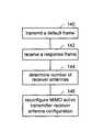
- FIG. 4is a logic diagram of a method for initiating a MIMO wireless communication by a transmitting device.
- the processbegins at step 140 where the transmitting device transmits a frame formatted in accordance with a default MIMO active transmitter-receiver antenna configuration to a target receiver.
- the frame formatted in accordance with the default MIMO active transmitter-receiver antenna configurationis a data frame that is based on an assumed number of receiver antennas and a corresponding number of transmit antennas.
- the target receiveris an access point, where the frame is a probe request.
- the transmitting devicereceives at least one response frame from the target receiver.
- the response frameis an acknowledgement that includes an indication of the receiver's number of antennas.
- the response framemay be from an access point that includes a response to a probe request frame.
- the response framemay include a signal and/or service field that includes an indication of the receiver's number of antennas.
- step 144the transmitting device determines a number of receiver antennas of the target receiver from the at least one response frame.
- the processthen proceeds to step 146 where the transmitting device reconfigures the MIMO active transmitter-receiver antenna configuration from the default MIMO active transmitter-receiver antenna configuration based on the at least one response frame. In one embodiment, the transmitting device reconfigures the active transmitter-receiver antenna configuration such that the number of transmit antennas equals the number of receiver antennas. In another embodiment, the transmitting device reconfigures the active transmitter-receiver antenna configuration such that the number of transmit antennas is greater than the number of receiver antennas for asymmetric MIMO communications.
- the transmitting devicemay further determine which of a plurality of transmitter antennas to include in the reconfigured MIMO active transmitter-receiver antenna configuration based on at least one of supported date rate and a predetermined grouping of the plurality of transmitter antennas.
- FIG. 5is a logic diagram of a method for selecting transmit antennas for a MIMO communication by a transmitting device.
- the processbegins at step 150 where the transmitting device determines a number of receiver antennas of a targeted receiver, wherein the number of receiver antennas is less than a number of transmitter antennas.
- the processthen proceeds to step 152 where the transmitting device equates a number of active transmitter antennas to the number of receiver antennas.
- the transmitting deviceselects a set of the transmitter antennas based on the number of active transmitter antennas to produce a selected set of transmitter antennas.
- the transmitting deviceselects the set of the transmitter antennas by selecting the set of the transmitter antennas from a list of predetermined groupings of the plurality of transmitter antennas, wherein a number of the transmitter antennas in a grouping corresponds to the number of receive antennas.
- the transmitting devicetransmits a frame to the targeted receiver via the selected set of transmitter antennas.
- the framehas a given data rate, which may be set from the lowest data rate for the antenna configuration to the highest data rate for the antenna configuration.
- the data ratemay be set at the highest data rate or at some mid point data rate.
- step 158the transmitting device determines whether an acknowledgement has been received for the frame within a given time period or within a given number of retransmissions of the frame. If not, the process proceeds to step 162 where the transmitting device selects another set of the transmitter antennas when an acknowledgement of receipt of the frame is not received from the targeted receiver. If the acknowledgement is received, the process proceeds to step 160 where the transmitting device uses the selected transmitter antennas. As an alternative to step 160 , the transmitting device may increase the data rate and varying the transmit antenna configuration to determine if a different transmit antenna configuration will provide a higher data rate.
- the term “substantially” or “approximately”, as may be used herein,provides an industry-accepted tolerance to its corresponding term and/or relativity between items. Such an industry-accepted tolerance ranges from less than one percent to twenty percent and corresponds to, but is not limited to, component values, integrated circuit process variations, temperature variations, rise and fall times, and/or thermal noise. Such relativity between items ranges from a difference of a few percent to magnitude differences.
- operably coupledincludes direct coupling and indirect coupling via another component, element, circuit, or module where, for indirect coupling, the intervening component, element, circuit, or module does not modify the information of a signal but may adjust its current level, voltage level, and/or power level.
- inferred couplingi.e., where one element is coupled to another element by inference
- inferred couplingincludes direct and indirect coupling between two elements in the same manner as “operably coupled”.
- the term “compares favorably”, as may be used herein,indicates that a comparison between two or more elements, items, signals, etc., provides a desired relationship. For example, when the desired relationship is that signal 1 has a greater magnitude than signal 2 , a favorable comparison may be achieved when the magnitude of signal 1 is greater than that of signal 2 or when the magnitude of signal 2 is less than that of signal 1 .
Landscapes
- Engineering & Computer Science (AREA)
- Computer Networks & Wireless Communication (AREA)
- Signal Processing (AREA)
- Mobile Radio Communication Systems (AREA)
- Radio Transmission System (AREA)
Abstract
Description
Claims (9)
Priority Applications (7)
| Application Number | Priority Date | Filing Date | Title |
|---|---|---|---|
| US11/132,516US8068550B2 (en) | 2005-01-28 | 2005-05-19 | Initiation of a MIMO communication |
| DE602005026364TDE602005026364D1 (en) | 2005-01-28 | 2005-09-23 | Initialization of a MIMO communication |
| EP05020803AEP1686701B1 (en) | 2005-01-28 | 2005-09-23 | Initiation of a MIMO communication |
| CN200610006883.2ACN1825779B (en) | 2005-01-28 | 2006-01-25 | Method for initiation of a mimo communication and radio frequency emitter |
| TW095102818ATWI330953B (en) | 2005-01-28 | 2006-01-25 | Initiation of a mimo communication |
| US13/279,558US8295385B2 (en) | 2005-01-28 | 2011-10-24 | Initiation of a MIMO communication |
| US13/613,392US8913678B2 (en) | 2005-01-28 | 2012-09-13 | Initiation of a MIMO communication |
Applications Claiming Priority (2)
| Application Number | Priority Date | Filing Date | Title |
|---|---|---|---|
| US64820705P | 2005-01-28 | 2005-01-28 | |
| US11/132,516US8068550B2 (en) | 2005-01-28 | 2005-05-19 | Initiation of a MIMO communication |
Related Child Applications (1)
| Application Number | Title | Priority Date | Filing Date |
|---|---|---|---|
| US13/279,558ContinuationUS8295385B2 (en) | 2005-01-28 | 2011-10-24 | Initiation of a MIMO communication |
Publications (2)
| Publication Number | Publication Date |
|---|---|
| US20060171482A1 US20060171482A1 (en) | 2006-08-03 |
| US8068550B2true US8068550B2 (en) | 2011-11-29 |
Family
ID=36046636
Family Applications (3)
| Application Number | Title | Priority Date | Filing Date |
|---|---|---|---|
| US11/132,516Expired - Fee RelatedUS8068550B2 (en) | 2005-01-28 | 2005-05-19 | Initiation of a MIMO communication |
| US13/279,558Expired - Fee RelatedUS8295385B2 (en) | 2005-01-28 | 2011-10-24 | Initiation of a MIMO communication |
| US13/613,392Expired - LifetimeUS8913678B2 (en) | 2005-01-28 | 2012-09-13 | Initiation of a MIMO communication |
Family Applications After (2)
| Application Number | Title | Priority Date | Filing Date |
|---|---|---|---|
| US13/279,558Expired - Fee RelatedUS8295385B2 (en) | 2005-01-28 | 2011-10-24 | Initiation of a MIMO communication |
| US13/613,392Expired - LifetimeUS8913678B2 (en) | 2005-01-28 | 2012-09-13 | Initiation of a MIMO communication |
Country Status (5)
| Country | Link |
|---|---|
| US (3) | US8068550B2 (en) |
| EP (1) | EP1686701B1 (en) |
| CN (1) | CN1825779B (en) |
| DE (1) | DE602005026364D1 (en) |
| TW (1) | TWI330953B (en) |
Cited By (2)
| Publication number | Priority date | Publication date | Assignee | Title |
|---|---|---|---|---|
| US20120039324A1 (en)* | 2005-01-28 | 2012-02-16 | Broadcom Corporation | Initiation of a mimo communication |
| US20200313738A1 (en)* | 2019-04-01 | 2020-10-01 | Qualcomm Incorporated | Network-sensitive transmit diversity scheme |
Families Citing this family (22)
| Publication number | Priority date | Publication date | Assignee | Title |
|---|---|---|---|---|
| WO2005112318A2 (en)* | 2004-05-11 | 2005-11-24 | Wionics Research | Mimo system and mode table |
| US7486720B2 (en)* | 2005-05-11 | 2009-02-03 | Mitsubishi Electric Research Laboratories, Inc. | Training frames for MIMO stations |
| US8068872B2 (en) | 2005-10-06 | 2011-11-29 | Telefonaktiebolaget Lm Ericsson (Publ) | Signaling support for antenna selection using subset lists and subset masks |
| US7548729B2 (en)* | 2005-11-14 | 2009-06-16 | Intel Corporation | Techniques enabling fast transmit rates and antenna adaptation for wireless networks based on explicit feedback |
| US20070223402A1 (en)* | 2006-03-21 | 2007-09-27 | Shai Waxman | Device, system and method of extended-range wireless communication |
| CN101155012B (en)* | 2006-09-28 | 2013-05-01 | 中兴通讯股份有限公司 | Multi-antenna mode control method based on terminal |
| CN101154974B (en)* | 2006-09-28 | 2011-08-10 | 中兴通讯股份有限公司 | Multi-antenna mode control method based on base station |
| US20080146163A1 (en)* | 2006-12-14 | 2008-06-19 | Motorola, Inc. | Diversity control of multi-mode communication devices |
| US8452296B2 (en)* | 2007-06-18 | 2013-05-28 | Motorola Mobility Llc | Method and apparatus to facilitate use of default transmitter-receiver configurations |
| US8176378B2 (en)* | 2007-09-07 | 2012-05-08 | Broadcom Corporation | Method and system for a transmitting antenna selection failure recovery mode |
| HUE055563T2 (en) | 2008-02-04 | 2021-12-28 | Nokia Technologies Oy | Method and apparatus for conveying antenna configuration information via masking |
| ES2733016T3 (en)* | 2011-06-24 | 2019-11-27 | Sun Patent Trust | Transmission device, transmission method, reception device and reception method |
| WO2014030714A1 (en) | 2012-08-24 | 2014-02-27 | 日本電気株式会社 | Remote communication system, server device, remote communication method, and program |
| WO2015057097A1 (en) | 2013-10-18 | 2015-04-23 | Motorola Solutions, Inc. | Method of and system for provisioning public safety communication devices via a wireless local area network protocol to communicate with one another in a common talk group configuration |
| US9270303B2 (en)* | 2013-12-30 | 2016-02-23 | Broadcom Corporation | Configurable receiver architecture for carrier aggregation with multiple-input multiple-output |
| US11252555B2 (en)* | 2014-07-11 | 2022-02-15 | Apple Inc. | Receive operation mode indication for power save |
| US10091725B2 (en) | 2014-07-11 | 2018-10-02 | Apple Inc. | Outage delay indication and exploitation |
| WO2016048210A1 (en)* | 2014-09-26 | 2016-03-31 | Telefonaktiebolaget L M Ericsson (Publ) | Detecting neighbor cell system information by low complexity user equipment |
| KR102429965B1 (en) | 2016-02-19 | 2022-08-08 | 삼성전자주식회사 | Method and Apparatus for Selecting Rx Antenna Set |
| CN108882369B (en)* | 2017-05-12 | 2020-11-13 | 大唐移动通信设备有限公司 | Signal processing method, system, access point and mobile station |
| US11477821B2 (en) | 2017-12-20 | 2022-10-18 | Telefonaktiebolaget Lm Ericsson (Publ) | Uplink transmissions in a wireless communications network |
| US11451270B2 (en) | 2020-07-29 | 2022-09-20 | Samsung Electronics Co., Ltd. | Method and apparatus for end-to-end gigahertz beamforming system |
Citations (15)
| Publication number | Priority date | Publication date | Assignee | Title |
|---|---|---|---|---|
| WO2002093819A1 (en) | 2001-05-16 | 2002-11-21 | Qualcomm Incorporated | Method and apparatus for allocating resources in a multiple-input multiple-output (mimo) communication system |
| US20020193146A1 (en) | 2001-06-06 | 2002-12-19 | Mark Wallace | Method and apparatus for antenna diversity in a wireless communication system |
| US20030003863A1 (en)* | 2001-05-04 | 2003-01-02 | Jorn Thielecke | Link adaptation for MIMO transmission schemes |
| US20030072452A1 (en)* | 2001-10-04 | 2003-04-17 | Mody Apurva N. | Preamble structures for single-input, single-output (SISO) and multi-input, multi-output (MIMO) communication systems |
| WO2004039011A2 (en) | 2002-10-25 | 2004-05-06 | Qualcomm Incorporated | Mimo wlan system |
| US20050111419A1 (en)* | 2003-11-20 | 2005-05-26 | Samsung Electronics Co., Ltd. | Method of performing communication over wireless network including multiple input/multiple output stations |
| US20050135318A1 (en)* | 2003-10-15 | 2005-06-23 | Qualcomm Incorporated | High speed media access control with legacy system interoperability |
| US20050152387A1 (en)* | 2004-01-09 | 2005-07-14 | Yoriko Utsunomiya | Communication method, communication apparatus, and communication system |
| US20050219999A1 (en)* | 2004-04-02 | 2005-10-06 | Lg Electronics Inc. | Frame structure of uplink control information transmission channel in MIMO communication system |
| US20050265225A1 (en)* | 2004-05-11 | 2005-12-01 | Orion Microelectronics Corporation | MIMO system and mode table |
| US20050288062A1 (en)* | 2004-06-23 | 2005-12-29 | Hammerschmidt Joachim S | Method and apparatus for selecting a transmission mode based upon packet size in a multiple antenna communication system |
| US20060034178A1 (en)* | 2004-08-13 | 2006-02-16 | Samsung Electronics Co., Ltd. | Wireless LAN communication method and apparatus |
| US7103325B1 (en)* | 2002-04-05 | 2006-09-05 | Nortel Networks Limited | Adaptive modulation and coding |
| US20080108310A1 (en)* | 2004-06-22 | 2008-05-08 | Wen Tong | Closed Loop Mimo Systems and Methods |
| US7697625B2 (en)* | 2004-02-11 | 2010-04-13 | Lg Electronics Inc. | Method and system for transmitting and receiving data streams |
Family Cites Families (14)
| Publication number | Priority date | Publication date | Assignee | Title |
|---|---|---|---|---|
| US7224704B2 (en)* | 2002-04-01 | 2007-05-29 | Texas Instruments Incorporated | Wireless network scheduling data frames including physical layer configuration |
| US7167708B2 (en)* | 2003-02-24 | 2007-01-23 | Autocell Laboratories Inc. | Wireless channel selection apparatus including scanning logic |
| ATE487291T1 (en)* | 2003-08-27 | 2010-11-15 | Wavion Ltd | WIFI CAPACITY EXPANSION BY USING SDM |
| US8233462B2 (en)* | 2003-10-15 | 2012-07-31 | Qualcomm Incorporated | High speed media access control and direct link protocol |
| US8483105B2 (en)* | 2003-10-15 | 2013-07-09 | Qualcomm Incorporated | High speed media access control |
| US7616698B2 (en)* | 2003-11-04 | 2009-11-10 | Atheros Communications, Inc. | Multiple-input multiple output system and method |
| US8983467B2 (en)* | 2003-12-09 | 2015-03-17 | Lsi Corporation | Method and apparatus for access point selection using channel correlation in a wireless communication system |
| US7450489B2 (en)* | 2003-12-30 | 2008-11-11 | Intel Corporation | Multiple-antenna communication systems and methods for communicating in wireless local area networks that include single-antenna communication devices |
| US7324605B2 (en)* | 2004-01-12 | 2008-01-29 | Intel Corporation | High-throughput multicarrier communication systems and methods for exchanging channel state information |
| US7519035B2 (en)* | 2004-02-23 | 2009-04-14 | Sharp Laboratories Of America, Inc. | Method to negotiate consumed power versus medium occupancy time in MIMO based WLAN systems using admission control |
| US20060034244A1 (en)* | 2004-08-11 | 2006-02-16 | Interdigital Technology Corporation | Method and system for link adaptation in an orthogonal frequency division multiplexing (OFDM) wireless communication system |
| US8504110B2 (en)* | 2004-09-10 | 2013-08-06 | Interdigital Technology Corporation | Method and apparatus for transferring smart antenna capability information |
| US7882412B2 (en)* | 2004-10-05 | 2011-02-01 | Sanjiv Nanda | Enhanced block acknowledgement |
| US8068550B2 (en)* | 2005-01-28 | 2011-11-29 | Broadcom Corporation | Initiation of a MIMO communication |
- 2005
- 2005-05-19USUS11/132,516patent/US8068550B2/ennot_activeExpired - Fee Related
- 2005-09-23DEDE602005026364Tpatent/DE602005026364D1/ennot_activeExpired - Lifetime
- 2005-09-23EPEP05020803Apatent/EP1686701B1/ennot_activeExpired - Lifetime
- 2006
- 2006-01-25CNCN200610006883.2Apatent/CN1825779B/ennot_activeExpired - Fee Related
- 2006-01-25TWTW095102818Apatent/TWI330953B/ennot_activeIP Right Cessation
- 2011
- 2011-10-24USUS13/279,558patent/US8295385B2/ennot_activeExpired - Fee Related
- 2012
- 2012-09-13USUS13/613,392patent/US8913678B2/ennot_activeExpired - Lifetime
Patent Citations (16)
| Publication number | Priority date | Publication date | Assignee | Title |
|---|---|---|---|---|
| US20030003863A1 (en)* | 2001-05-04 | 2003-01-02 | Jorn Thielecke | Link adaptation for MIMO transmission schemes |
| CN1522512A (en) | 2001-05-16 | 2004-08-18 | �����ɷ� | Method and device for allocating resources in a multiple-input multiple-output (MIMO) communication system |
| WO2002093819A1 (en) | 2001-05-16 | 2002-11-21 | Qualcomm Incorporated | Method and apparatus for allocating resources in a multiple-input multiple-output (mimo) communication system |
| US20020193146A1 (en) | 2001-06-06 | 2002-12-19 | Mark Wallace | Method and apparatus for antenna diversity in a wireless communication system |
| US20030072452A1 (en)* | 2001-10-04 | 2003-04-17 | Mody Apurva N. | Preamble structures for single-input, single-output (SISO) and multi-input, multi-output (MIMO) communication systems |
| US7103325B1 (en)* | 2002-04-05 | 2006-09-05 | Nortel Networks Limited | Adaptive modulation and coding |
| WO2004039011A2 (en) | 2002-10-25 | 2004-05-06 | Qualcomm Incorporated | Mimo wlan system |
| US20050135318A1 (en)* | 2003-10-15 | 2005-06-23 | Qualcomm Incorporated | High speed media access control with legacy system interoperability |
| US20050111419A1 (en)* | 2003-11-20 | 2005-05-26 | Samsung Electronics Co., Ltd. | Method of performing communication over wireless network including multiple input/multiple output stations |
| US20050152387A1 (en)* | 2004-01-09 | 2005-07-14 | Yoriko Utsunomiya | Communication method, communication apparatus, and communication system |
| US7697625B2 (en)* | 2004-02-11 | 2010-04-13 | Lg Electronics Inc. | Method and system for transmitting and receiving data streams |
| US20050219999A1 (en)* | 2004-04-02 | 2005-10-06 | Lg Electronics Inc. | Frame structure of uplink control information transmission channel in MIMO communication system |
| US20050265225A1 (en)* | 2004-05-11 | 2005-12-01 | Orion Microelectronics Corporation | MIMO system and mode table |
| US20080108310A1 (en)* | 2004-06-22 | 2008-05-08 | Wen Tong | Closed Loop Mimo Systems and Methods |
| US20050288062A1 (en)* | 2004-06-23 | 2005-12-29 | Hammerschmidt Joachim S | Method and apparatus for selecting a transmission mode based upon packet size in a multiple antenna communication system |
| US20060034178A1 (en)* | 2004-08-13 | 2006-02-16 | Samsung Electronics Co., Ltd. | Wireless LAN communication method and apparatus |
Cited By (6)
| Publication number | Priority date | Publication date | Assignee | Title |
|---|---|---|---|---|
| US20120039324A1 (en)* | 2005-01-28 | 2012-02-16 | Broadcom Corporation | Initiation of a mimo communication |
| US8295385B2 (en)* | 2005-01-28 | 2012-10-23 | Broadcom Corporation | Initiation of a MIMO communication |
| US20130016709A1 (en)* | 2005-01-28 | 2013-01-17 | Broadcom Corporation | Initiation of a mimo communication |
| US8913678B2 (en)* | 2005-01-28 | 2014-12-16 | Broadcom Corporation | Initiation of a MIMO communication |
| US20200313738A1 (en)* | 2019-04-01 | 2020-10-01 | Qualcomm Incorporated | Network-sensitive transmit diversity scheme |
| US11569886B2 (en)* | 2019-04-01 | 2023-01-31 | Qualcomm Incorporated | Network-sensitive transmit diversity scheme |
Also Published As
| Publication number | Publication date |
|---|---|
| CN1825779B (en) | 2011-06-08 |
| EP1686701A1 (en) | 2006-08-02 |
| EP1686701B1 (en) | 2011-02-16 |
| US20130016709A1 (en) | 2013-01-17 |
| TWI330953B (en) | 2010-09-21 |
| US8913678B2 (en) | 2014-12-16 |
| US20120039324A1 (en) | 2012-02-16 |
| US20060171482A1 (en) | 2006-08-03 |
| DE602005026364D1 (en) | 2011-03-31 |
| TW200705860A (en) | 2007-02-01 |
| CN1825779A (en) | 2006-08-30 |
| US8295385B2 (en) | 2012-10-23 |
Similar Documents
| Publication | Publication Date | Title |
|---|---|---|
| US8295385B2 (en) | Initiation of a MIMO communication | |
| US7711061B2 (en) | Preamble formats supporting high-throughput MIMO WLAN and auto-detection | |
| US7738356B2 (en) | Multiple stream cyclic-shifted delay transmitter | |
| US8891642B2 (en) | Mixed mode preamble for MIMO wireless communications | |
| US8472901B2 (en) | Gain control in a multiple RF transceiver integrated circuit | |
| US9344535B2 (en) | Multiple protocol wireless communications in a WLAN | |
| US8081687B2 (en) | Received signal determination based upon frame classification | |
| US7924764B2 (en) | Method and apparatus for packet processing | |
| US20070025392A1 (en) | Modulation-type discrimination in a wireless local area network | |
| US9516483B2 (en) | Wireless communication between stations of differing protocols | |
| US20070076811A1 (en) | Channel estimation for orthogonal preambles in a MIMO system | |
| EP1746757A1 (en) | Space-time and/or space-frequency block coding using complex signal swapping | |
| US8774327B2 (en) | Adjustable RF receiver | |
| US20060239372A1 (en) | Reduced feedback for beamforming in a wireless communication | |
| US7738584B2 (en) | Beamforming in a wireless communication with a partial estimation to reduce overhead |
Legal Events
| Date | Code | Title | Description |
|---|---|---|---|
| AS | Assignment | Owner name:BROADCOM CORPORATION, CALIFORNIA Free format text:ASSIGNMENT OF ASSIGNORS INTEREST;ASSIGNOR:TRACHEWSKY, JASON A.;REEL/FRAME:016162/0913 Effective date:20050518 | |
| FEPP | Fee payment procedure | Free format text:PAYOR NUMBER ASSIGNED (ORIGINAL EVENT CODE: ASPN); ENTITY STATUS OF PATENT OWNER: LARGE ENTITY | |
| REMI | Maintenance fee reminder mailed | ||
| LAPS | Lapse for failure to pay maintenance fees | ||
| STCH | Information on status: patent discontinuation | Free format text:PATENT EXPIRED DUE TO NONPAYMENT OF MAINTENANCE FEES UNDER 37 CFR 1.362 | |
| FP | Lapsed due to failure to pay maintenance fee | Effective date:20151129 | |
| AS | Assignment | Owner name:BANK OF AMERICA, N.A., AS COLLATERAL AGENT, NORTH CAROLINA Free format text:PATENT SECURITY AGREEMENT;ASSIGNOR:BROADCOM CORPORATION;REEL/FRAME:037806/0001 Effective date:20160201 Owner name:BANK OF AMERICA, N.A., AS COLLATERAL AGENT, NORTH Free format text:PATENT SECURITY AGREEMENT;ASSIGNOR:BROADCOM CORPORATION;REEL/FRAME:037806/0001 Effective date:20160201 | |
| AS | Assignment | Owner name:AVAGO TECHNOLOGIES GENERAL IP (SINGAPORE) PTE. LTD., SINGAPORE Free format text:ASSIGNMENT OF ASSIGNORS INTEREST;ASSIGNOR:BROADCOM CORPORATION;REEL/FRAME:041706/0001 Effective date:20170120 Owner name:AVAGO TECHNOLOGIES GENERAL IP (SINGAPORE) PTE. LTD Free format text:ASSIGNMENT OF ASSIGNORS INTEREST;ASSIGNOR:BROADCOM CORPORATION;REEL/FRAME:041706/0001 Effective date:20170120 | |
| AS | Assignment | Owner name:BROADCOM CORPORATION, CALIFORNIA Free format text:TERMINATION AND RELEASE OF SECURITY INTEREST IN PATENTS;ASSIGNOR:BANK OF AMERICA, N.A., AS COLLATERAL AGENT;REEL/FRAME:041712/0001 Effective date:20170119 |