US8068521B2 - Laser source that generates a plurality of alternative wavelength output beams - Google Patents
Laser source that generates a plurality of alternative wavelength output beamsDownload PDFInfo
- Publication number
- US8068521B2 US8068521B2US12/960,742US96074210AUS8068521B2US 8068521 B2US8068521 B2US 8068521B2US 96074210 AUS96074210 AUS 96074210AUS 8068521 B2US8068521 B2US 8068521B2
- Authority
- US
- United States
- Prior art keywords
- gain medium
- laser source
- power
- feedback device
- output beams
- Prior art date
- Legal status (The legal status is an assumption and is not a legal conclusion. Google has not performed a legal analysis and makes no representation as to the accuracy of the status listed.)
- Active
Links
- 230000003287optical effectEffects0.000claimsdescription47
- 238000000034methodMethods0.000claimsdescription14
- 238000003384imaging methodMethods0.000claimsdescription7
- 230000001360synchronised effectEffects0.000claimsdescription4
- 238000012544monitoring processMethods0.000claimsdescription3
- 239000007789gasSubstances0.000description67
- 238000013461designMethods0.000description39
- 239000011248coating agentSubstances0.000description11
- 238000000576coating methodMethods0.000description11
- 239000000126substanceSubstances0.000description11
- 239000000463materialSubstances0.000description8
- 238000010521absorption reactionMethods0.000description7
- 238000001514detection methodMethods0.000description7
- 230000003595spectral effectEffects0.000description7
- 238000001228spectrumMethods0.000description7
- 238000003860storageMethods0.000description6
- QGZKDVFQNNGYKY-UHFFFAOYSA-NAmmoniaChemical compoundNQGZKDVFQNNGYKY-UHFFFAOYSA-N0.000description4
- IJGRMHOSHXDMSA-UHFFFAOYSA-NAtomic nitrogenChemical compoundN#NIJGRMHOSHXDMSA-UHFFFAOYSA-N0.000description4
- GQPLMRYTRLFLPF-UHFFFAOYSA-NNitrous OxideChemical compound[O-][N+]#NGQPLMRYTRLFLPF-UHFFFAOYSA-N0.000description4
- 238000002310reflectometryMethods0.000description4
- 239000004065semiconductorSubstances0.000description4
- OAKJQQAXSVQMHS-UHFFFAOYSA-NHydrazineChemical compoundNNOAKJQQAXSVQMHS-UHFFFAOYSA-N0.000description3
- 230000004888barrier functionEffects0.000description3
- 239000012530fluidSubstances0.000description3
- 238000005259measurementMethods0.000description3
- VNWKTOKETHGBQD-UHFFFAOYSA-NmethaneChemical compoundCVNWKTOKETHGBQD-UHFFFAOYSA-N0.000description3
- HGINCPLSRVDWNT-UHFFFAOYSA-NAcroleinChemical compoundC=CC=OHGINCPLSRVDWNT-UHFFFAOYSA-N0.000description2
- OTMSDBZUPAUEDD-UHFFFAOYSA-NEthaneChemical compoundCCOTMSDBZUPAUEDD-UHFFFAOYSA-N0.000description2
- VGGSQFUCUMXWEO-UHFFFAOYSA-NEtheneChemical compoundC=CVGGSQFUCUMXWEO-UHFFFAOYSA-N0.000description2
- 239000005977EthyleneSubstances0.000description2
- MHAJPDPJQMAIIY-UHFFFAOYSA-NHydrogen peroxideChemical compoundOOMHAJPDPJQMAIIY-UHFFFAOYSA-N0.000description2
- PXHVJJICTQNCMI-UHFFFAOYSA-NNickelChemical compound[Ni]PXHVJJICTQNCMI-UHFFFAOYSA-N0.000description2
- 229910018503SF6Inorganic materials0.000description2
- 238000004847absorption spectroscopyMethods0.000description2
- 230000000712assemblyEffects0.000description2
- 238000000429assemblyMethods0.000description2
- 238000005102attenuated total reflectionMethods0.000description2
- 230000008901benefitEffects0.000description2
- 230000008859changeEffects0.000description2
- 238000001816coolingMethods0.000description2
- 231100001261hazardousToxicity0.000description2
- 239000000383hazardous chemicalSubstances0.000description2
- 238000010438heat treatmentMethods0.000description2
- 238000004519manufacturing processMethods0.000description2
- 229910052751metalInorganic materials0.000description2
- 239000002184metalSubstances0.000description2
- 239000000203mixtureSubstances0.000description2
- HDZGCSFEDULWCS-UHFFFAOYSA-NmonomethylhydrazineChemical compoundCNNHDZGCSFEDULWCS-UHFFFAOYSA-N0.000description2
- 229910052757nitrogenInorganic materials0.000description2
- 239000001272nitrous oxideSubstances0.000description2
- 239000007787solidSubstances0.000description2
- SFZCNBIFKDRMGX-UHFFFAOYSA-Nsulfur hexafluorideChemical compoundFS(F)(F)(F)(F)FSFZCNBIFKDRMGX-UHFFFAOYSA-N0.000description2
- 229960000909sulfur hexafluorideDrugs0.000description2
- 238000012546transferMethods0.000description2
- 230000007704transitionEffects0.000description2
- ZAMOUSCENKQFHK-UHFFFAOYSA-NChlorine atomChemical compound[Cl]ZAMOUSCENKQFHK-UHFFFAOYSA-N0.000description1
- RYGMFSIKBFXOCR-UHFFFAOYSA-NCopperChemical compound[Cu]RYGMFSIKBFXOCR-UHFFFAOYSA-N0.000description1
- 239000004338DichlorodifluoromethaneSubstances0.000description1
- 239000004593EpoxySubstances0.000description1
- 229910005542GaSbInorganic materials0.000description1
- 229910000530Gallium indium arsenideInorganic materials0.000description1
- VEXZGXHMUGYJMC-UHFFFAOYSA-NHydrochloric acidChemical compoundClVEXZGXHMUGYJMC-UHFFFAOYSA-N0.000description1
- WETWJCDKMRHUPV-UHFFFAOYSA-Nacetyl chlorideChemical compoundCC(Cl)=OWETWJCDKMRHUPV-UHFFFAOYSA-N0.000description1
- 239000012346acetyl chlorideSubstances0.000description1
- 229910021529ammoniaInorganic materials0.000description1
- 238000004458analytical methodMethods0.000description1
- 230000002238attenuated effectEffects0.000description1
- QKSKPIVNLNLAAV-UHFFFAOYSA-Nbis(2-chloroethyl) sulfideChemical compoundClCCSCCClQKSKPIVNLNLAAV-UHFFFAOYSA-N0.000description1
- 239000005387chalcogenide glassSubstances0.000description1
- 239000013043chemical agentSubstances0.000description1
- 238000006243chemical reactionMethods0.000description1
- 239000000460chlorineSubstances0.000description1
- 229910052801chlorineInorganic materials0.000description1
- 238000004891communicationMethods0.000description1
- 239000004020conductorSubstances0.000description1
- 238000010276constructionMethods0.000description1
- 229910052802copperInorganic materials0.000description1
- 239000010949copperSubstances0.000description1
- SBYXRAKIOMOBFF-UHFFFAOYSA-Ncopper tungstenChemical compound[Cu].[W]SBYXRAKIOMOBFF-UHFFFAOYSA-N0.000description1
- 239000013078crystalSubstances0.000description1
- 230000007423decreaseEffects0.000description1
- 230000001419dependent effectEffects0.000description1
- 238000007516diamond turningMethods0.000description1
- PXBRQCKWGAHEHS-UHFFFAOYSA-NdichlorodifluoromethaneChemical compoundFC(F)(Cl)ClPXBRQCKWGAHEHS-UHFFFAOYSA-N0.000description1
- 235000019404dichlorodifluoromethaneNutrition0.000description1
- 230000000694effectsEffects0.000description1
- 230000005611electricityEffects0.000description1
- 238000005516engineering processMethods0.000description1
- 230000007613environmental effectEffects0.000description1
- 239000002360explosiveSubstances0.000description1
- 230000006870functionEffects0.000description1
- 239000011521glassSubstances0.000description1
- 230000020169heat generationEffects0.000description1
- 238000002347injectionMethods0.000description1
- 239000007924injectionSubstances0.000description1
- 239000012212insulatorSubstances0.000description1
- 230000010354integrationEffects0.000description1
- 239000007788liquidSubstances0.000description1
- 239000011159matrix materialSubstances0.000description1
- 238000000465mouldingMethods0.000description1
- 229910052759nickelInorganic materials0.000description1
- 229910000069nitrogen hydrideInorganic materials0.000description1
- 230000009965odorless effectEffects0.000description1
- 230000005855radiationEffects0.000description1
- 238000005215recombinationMethods0.000description1
- 230000006798recombinationEffects0.000description1
- 230000009467reductionEffects0.000description1
- SBIBMFFZSBJNJF-UHFFFAOYSA-Nselenium;zincChemical compound[Se]=[Zn]SBIBMFFZSBJNJF-UHFFFAOYSA-N0.000description1
- 230000035945sensitivityEffects0.000description1
- 229910000679solderInorganic materials0.000description1
- 239000000758substrateSubstances0.000description1
- 238000012360testing methodMethods0.000description1
- 231100000331toxicToxicity0.000description1
- 230000002588toxic effectEffects0.000description1
- 239000002341toxic gasSubstances0.000description1
- 238000003466weldingMethods0.000description1
Images


Classifications
- H—ELECTRICITY
- H01—ELECTRIC ELEMENTS
- H01S—DEVICES USING THE PROCESS OF LIGHT AMPLIFICATION BY STIMULATED EMISSION OF RADIATION [LASER] TO AMPLIFY OR GENERATE LIGHT; DEVICES USING STIMULATED EMISSION OF ELECTROMAGNETIC RADIATION IN WAVE RANGES OTHER THAN OPTICAL
- H01S5/00—Semiconductor lasers
- H01S5/10—Construction or shape of the optical resonator, e.g. extended or external cavity, coupled cavities, bent-guide, varying width, thickness or composition of the active region
- H01S5/14—External cavity lasers
- H01S5/141—External cavity lasers using a wavelength selective device, e.g. a grating or etalon
- G—PHYSICS
- G01—MEASURING; TESTING
- G01N—INVESTIGATING OR ANALYSING MATERIALS BY DETERMINING THEIR CHEMICAL OR PHYSICAL PROPERTIES
- G01N21/00—Investigating or analysing materials by the use of optical means, i.e. using sub-millimetre waves, infrared, visible or ultraviolet light
- G01N21/17—Systems in which incident light is modified in accordance with the properties of the material investigated
- G01N21/25—Colour; Spectral properties, i.e. comparison of effect of material on the light at two or more different wavelengths or wavelength bands
- G01N21/31—Investigating relative effect of material at wavelengths characteristic of specific elements or molecules, e.g. atomic absorption spectrometry
- G01N21/35—Investigating relative effect of material at wavelengths characteristic of specific elements or molecules, e.g. atomic absorption spectrometry using infrared light
- G01N21/3504—Investigating relative effect of material at wavelengths characteristic of specific elements or molecules, e.g. atomic absorption spectrometry using infrared light for analysing gases, e.g. multi-gas analysis
- H—ELECTRICITY
- H01—ELECTRIC ELEMENTS
- H01S—DEVICES USING THE PROCESS OF LIGHT AMPLIFICATION BY STIMULATED EMISSION OF RADIATION [LASER] TO AMPLIFY OR GENERATE LIGHT; DEVICES USING STIMULATED EMISSION OF ELECTROMAGNETIC RADIATION IN WAVE RANGES OTHER THAN OPTICAL
- H01S3/00—Lasers, i.e. devices using stimulated emission of electromagnetic radiation in the infrared, visible or ultraviolet wave range
- H01S3/05—Construction or shape of optical resonators; Accommodation of active medium therein; Shape of active medium
- H01S3/08—Construction or shape of optical resonators or components thereof
- H01S3/08059—Constructional details of the reflector, e.g. shape
- H—ELECTRICITY
- H01—ELECTRIC ELEMENTS
- H01S—DEVICES USING THE PROCESS OF LIGHT AMPLIFICATION BY STIMULATED EMISSION OF RADIATION [LASER] TO AMPLIFY OR GENERATE LIGHT; DEVICES USING STIMULATED EMISSION OF ELECTROMAGNETIC RADIATION IN WAVE RANGES OTHER THAN OPTICAL
- H01S3/00—Lasers, i.e. devices using stimulated emission of electromagnetic radiation in the infrared, visible or ultraviolet wave range
- H01S3/10—Controlling the intensity, frequency, phase, polarisation or direction of the emitted radiation, e.g. switching, gating, modulating or demodulating
- H01S3/105—Controlling the intensity, frequency, phase, polarisation or direction of the emitted radiation, e.g. switching, gating, modulating or demodulating by controlling the mutual position or the reflecting properties of the reflectors of the cavity, e.g. by controlling the cavity length
- H01S3/1055—Controlling the intensity, frequency, phase, polarisation or direction of the emitted radiation, e.g. switching, gating, modulating or demodulating by controlling the mutual position or the reflecting properties of the reflectors of the cavity, e.g. by controlling the cavity length one of the reflectors being constituted by a diffraction grating
- H—ELECTRICITY
- H01—ELECTRIC ELEMENTS
- H01S—DEVICES USING THE PROCESS OF LIGHT AMPLIFICATION BY STIMULATED EMISSION OF RADIATION [LASER] TO AMPLIFY OR GENERATE LIGHT; DEVICES USING STIMULATED EMISSION OF ELECTROMAGNETIC RADIATION IN WAVE RANGES OTHER THAN OPTICAL
- H01S5/00—Semiconductor lasers
- H01S5/02—Structural details or components not essential to laser action
- H01S5/022—Mountings; Housings
- H01S5/023—Mount members, e.g. sub-mount members
- H01S5/02325—Mechanically integrated components on mount members or optical micro-benches
- H—ELECTRICITY
- H01—ELECTRIC ELEMENTS
- H01S—DEVICES USING THE PROCESS OF LIGHT AMPLIFICATION BY STIMULATED EMISSION OF RADIATION [LASER] TO AMPLIFY OR GENERATE LIGHT; DEVICES USING STIMULATED EMISSION OF ELECTROMAGNETIC RADIATION IN WAVE RANGES OTHER THAN OPTICAL
- H01S5/00—Semiconductor lasers
- H01S5/02—Structural details or components not essential to laser action
- H01S5/024—Arrangements for thermal management
- H01S5/02407—Active cooling, e.g. the laser temperature is controlled by a thermo-electric cooler or water cooling
- H01S5/02415—Active cooling, e.g. the laser temperature is controlled by a thermo-electric cooler or water cooling by using a thermo-electric cooler [TEC], e.g. Peltier element
- H—ELECTRICITY
- H01—ELECTRIC ELEMENTS
- H01S—DEVICES USING THE PROCESS OF LIGHT AMPLIFICATION BY STIMULATED EMISSION OF RADIATION [LASER] TO AMPLIFY OR GENERATE LIGHT; DEVICES USING STIMULATED EMISSION OF ELECTROMAGNETIC RADIATION IN WAVE RANGES OTHER THAN OPTICAL
- H01S5/00—Semiconductor lasers
- H01S5/02—Structural details or components not essential to laser action
- H01S5/024—Arrangements for thermal management
- H01S5/02453—Heating, e.g. the laser is heated for stabilisation against temperature fluctuations of the environment
Definitions
- the usage, transportation, and storage of hazardous materialscreate many safety and environmental issues. More specifically, during usage, transportation, and storage of hazardous materials, leaks can release toxic or explosive gas into the surrounding environment. For example, industrial equipment used in the oil, gas, utility, and chemical industries can release toxic gas into the surrounding environment. As another example, hazardous gases can pose a threat to homeland security. In many cases, the hazardous gas is odorless, colorless, and spreads quickly. As a result thereof, it can be quite difficult to detect and locate the source of the leak.
- MIR rangemid infrared range
- the laser sourceIn order to detect a wide range of gases, the laser source must generate a set of sequential, specific output beams that span a portion or the entire the MIR range.
- emitting gases in many atmospheric environmentsare susceptible to intensity fluctuations due to air turbulence. This can make it very difficult to detect these emitting gases.
- the present inventionis directed to a laser source for emitting a set of output beams, with each of the output beams in the set having a different center wavelength.
- the laser sourceincludes a gain medium, a feedback assembly and a control system.
- the gain mediumincludes a first facet, and the gain medium is adapted to generate a beam that exits the first facet.
- the feedback assemblyincludes a feedback device and a device mover.
- the feedback deviceis positioned in the path of the beam that exits the first facet and the feedback device redirects at least a portion of the beam back to the gain medium.
- the device movercontinuously adjusts an angle of incidence of the beam on the feedback device.
- the control systemselectively directs pulses of power to the gain medium as the device mover is continuously adjusting the angle of incidence.
- the laser sourceincludes a position detector that generates a position signal that relates to the angle of incidence of the beam on the feedback device.
- the control systemcan selectively direct the pulses of power to the gain medium based on the position signal from the position detector.
- the position detectorcan include a plurality of encoder marks and an optical reader that monitors the encoder marks.
- the control systemcan selectively direct a pulse of power to the gain medium whenever the optical reader reads a predetermined number of encoder marks.
- the control systemcan determine a center wavelength of the output beam based on the position signal. With this design, the laser source rapidly and accurately generates one or more sets of sequential, wavelength specific output beams that span a predetermined detection range.
- the gain mediumcan be a QC gain medium.
- the gain mediumcan include a partly reflective second facet, and the output beams can exit the second facet.
- the second facetcan define a first end of an external cavity and the feedback device can defines a second end of the external cavity.
- the feedback deviceincludes a diffraction grating, and the device mover rapidly adjusts the angle of incidence of the beam on the diffraction grating.
- the device movercan include a voice coil motor that quickly pivots the feedback device back and forth about a pivot axis.
- the device movercan include a rotary motor that rotates the diffraction grating about a rotation axis.
- the feedback devicecan include a plurality of diffraction gratings, and the device mover can include a rotary motor that rotates the plurality of diffraction gratings about the rotation axis.
- the feedback deviceincludes a fixed diffraction grating, and one or more reflectors.
- the device moverincludes a rotary motor that rotates the one or more reflectors about a rotation axis.
- the feedback devicecan be moved to a plurality of alternative device positions with the device mover. Further, the control system can direct a pulse of power to the gain medium at each of the plurality of device positions so that the laser source generates the set of output beams, with each of the output beams in the set having a different center wavelength.
- the position detectorcan generate a first position signal when the feedback device is at a first device position and a second position signal when the feedback device is at a second device position.
- the control systemcan direct a pulse of power to the gain medium upon receipt of the first position signal, and the control system can direct another pulse of power to the gain medium upon receipt of the second position signal.
- the present inventionis directed to a sensor system for imaging an emitting gas.
- the imaging systemcan include an imager that captures a thermal image, and the laser source described above.
- the set of output beamsare directed at the emitting gas and one or more of the output beams are backscatter near and/or absorbed by the emitting gas.
- the gasabsorbs and attenuates the backscattered light.
- a shadow or contrast that corresponds to the emitting gasis clearly visible in the image that is captured by the imager.
- the sensor systemis very accurate and can be extremely lightweight, stable, rugged, small, self-contained, and portable.
- the present inventionis directed to one or more methods for generating a set of output beams.
- FIG. 1Ais simplified top illustration in partial cut-away of a laser source having features of the present invention
- FIG. 1Bis a simplified side illustration in partial cut-away of the laser source of FIG. 1B ;
- FIG. 2is a simplified graph that illustrates a center wavelength for a set of output beams
- FIG. 3Ais a graph that illustrates pulses of power directed to a gain medium versus angle of incidence
- FIG. 3Bis a graph that illustrates pulses of power directed to a gain medium versus position signals
- FIG. 3Cis a graph that illustrates pulses of power directed to a gain medium versus number of encoder marks
- FIG. 4Ais a simplified illustration of a position detector and a feedback assembly having features of the present invention in a first device position
- FIG. 4Bis a simplified illustration of the position detector and the feedback assembly of FIG. 4A in a second device position
- FIG. 5Ais a simplified illustration of another embodiment of a position detector and a feedback assembly having features of the present invention in a first device position;
- FIG. 5Bis a simplified illustration of the position detector and the feedback assembly of FIG. 5A in a second device position
- FIG. 6Ais a simplified illustration of still another embodiment of a position detector and a feedback assembly having features of the present invention in a first device position;
- FIG. 6Bis a simplified illustration of the position detector and the feedback assembly of FIG. 6A in a second device position
- FIG. 7is a simplified illustration of another embodiment of a laser source having features of the present invention.
- FIG. 8is simplified illustration of a gas sensor system having features of the present invention and an emitting gas
- FIG. 9is a simplified illustration of another embodiment of a gas sensor system having features of the present invention.
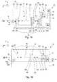
- FIG. 1Ais a simplified top illustration, in partial cut-away and FIG. 1B is a simplified side illustration, in partial cut-away of a laser source 10 that is suited for imaging, locating, detecting, and/or identifying an emitting gas (not shown in FIGS. 1A and 1B ) and/or other industrial or testing applications.
- the laser source 10is designed to rapidly and accurately generate one or more sets of sequential, wavelength specific output beams 12 that span a predetermined detection range. With this design, the set of output beams 12 from the laser source 10 can be specifically tailored to target the absorption features of the gases of interest. Further, in certain embodiments, because of the unique design disclosed herein, the laser source 10 can be extremely compact, hand-held, lightweight, stable, rugged, small, self-contained, and portable.
- the plurality of output beams 12traverse the same optical path and originate from the same gain medium.
- the laser source 10is a mid infrared (“MIR”) laser source and the output beams 12 in the set have a center wavelength in the MIR range of approximately 2-20 micrometers.
- the laser source 10can be designed to generate the set of sequential, specific output beams 12 that span the entire or just a portion of the MIR range.
- MIR laser sources 10are particularly useful in absorption spectroscopy applications since many gases of interest have strong, unique absorption signatures within the MIR range.
- the laser source 10can have generate one or more output beams 12 having a center wavelength of greater than or lesser than 2-20 micrometers.
- a number of Figuresinclude an orientation system that illustrates an X axis, a Y axis that is orthogonal to the X axis and a Z axis that is orthogonal to the X and Y axes. It should be noted that these axes can also be referred to as the first, second and third axes.
- the design of the laser source 10can be varied to achieve the desired type of gas detection or other usage of the laser source 10 .
- the laser source 10includes a source frame 14 , a gain medium 16 , a cavity optical assembly 18 , a power source 20 , a temperature controller 22 , an output optical assembly 24 , a wavelength dependant (“WD”) feedback assembly 26 , a position detector 28 , and a laser control system 30 that cooperate to generate the one or more sets of output beams 12 .
- the design of each of these componentscan be varied pursuant to the teachings provided herein. Further, it should be noted that the laser source 10 can be designed with more or fewer components than described herein.
- the source frame 14supports at least some of the components of the laser source 10 .
- the gain medium 16 , the cavity optical assembly 18 , the output optical assembly 24 , and the WD feedback assembly 26are each fixedly secured, in a rigid arrangement to the source frame 14 ; and (ii) the source frame 14 maintains these components in precise mechanical alignment to achieve the desired wavelength of each of the output beams 12 of the set.
- the laser control system 30 , the power source 20 , and the temperature controller 22can be secured to source frame 14 . With this design, all of the critical components are fixed to the source frame 14 in a stable manner, and the laser source 10 can be self-contained and extremely portable.
- the power source 20 , the temperature controller 22 , and/or the laser control system 30can be separate from and external to the source frame 14 .
- the design of the source frame 14can be varied to achieve the design requirements of the laser source 10 .
- the source frame 14includes a rigid mounting base 32 , a cover 34 that encloses the components of the laser source 10 , and a window 35 that allows the output beam 12 to exit the cover 34 .
- the source frame 32can be designed without the cover 34 , without the window 35 , and/or can have a configuration different from that illustrated in the Figures.
- the mounting base 32provides a rigid platform for fixedly mounting the gain medium 16 , the cavity optical assembly 18 , the output optical assembly 24 and the WD feedback assembly 26 .
- the mounting base 32is illustrated as being generally rectangular plate shaped.
- the mounting base 32is a single mechanical ground plane that provides structural integrity to the laser source 10 .
- the mounting base 32can have a configuration that is different than that illustrated in Figures.
- the mounting base 32is made of rigid material that has a relatively high thermal conductivity.
- the mounting base 32has a thermal conductivity of at least approximately 170 watts/meter K.
- the mounting base 32in addition to rigidly supporting the components of the laser source 10 , the mounting base 32 also readily transfers heat away from the gain medium 16 to the temperature controller 22 .
- the mounting base 32can be fabricated from a single, integral piece of copper, copper-tungsten or other material having a sufficiently high thermal conductivity. The one piece structure of the mounting base 32 maintains the fixed relationship of the components mounted thereto and contributes to the small size and portability of the laser source 10 .
- the cover 34is shaped somewhat similar to an inverted, open rectangular box.
- the cover 34is hermetically sealed to the mounting base 32 in an air tight manner. This allows the source frame 14 to provide a controlled environment around some of the components of the laser source 10 .
- the environment enclosed by the cover 34can be filled with a fluid such as nitrogen or an air/nitrogen mixture to keep out moisture and humidity; or it can be subjected to a vacuum.
- the overall size of the source frame 14is relatively small so that the laser source 10 is very portability.
- the source frame 14can have dimensions of approximately 20 centimeters (height) by 20 centimeters (width) by 20 centimeters (length) (where length is taken along the propagation direction of the laser beam) or less, and more preferably, the source frame 14 has dimensions of approximately 3 centimeters (height) by 4 centimeters (width) by 5 centimeters (length). Still alternatively, the source frame 14 can have dimensions of less than approximately 10 millimeters (height) by 25 millimeters (width) by 30 millimeters.
- the gain medium 16generates the output beams 12 .
- the gain medium 16is a semiconductor type laser that directly emits the output beams 12 without any frequency conversion.
- the term semiconductorshall include any solid crystalline substance having electrical conductivity greater than insulators but less than good conductors.
- the gain medium 16is a QC gain medium that is a unipolar semiconductor laser that includes a series of energy steps built into the material matrix while the crystal is being grown. With this design, electrons transmitted through the gain medium 16 emit one photon at each of the energy steps.
- the QC gain medium 16uses two different semiconductor materials such as InGaAs and AlInAs (grown on an InP or GaSb substrate for example) to form a series of potential wells and barriers for electron transitions. The thickness of these wells/barriers determines the wavelength characteristic of the gain medium 16 . Fabricating QC gain medium of different thickness enables production of the laser having different output frequencies within the MIR range.
- the “diode”has been replaced by a conduction band quantum well. Electrons are injected into the upper quantum well state and collected from the lower state using a superlattice structure. The upper and lower states are both within the conduction band. Replacing the diode with a single-carrier quantum well system means that the generated photon energy is no longer tied to the material bandgap. This removes the requirement for exotic new materials for each wavelength, and also removes Auger recombination as a problem issue in the active region.
- the superlattice and quantum wellcan be designed to provide lasing at almost any photon energy that is sufficiently below the conduction band quantum well barrier.
- QC gain mediumshall also include Interband Cascade Lasers (ICL) in addition to Quantum Cascade type media.
- ICL lasersuse a conduction-band to valence-band transition as in the traditional diode laser.
- the gain medium 16includes (i) a first facet 16 A that faces the cavity optical assembly 18 and the WD feedback assembly 26 , and (ii) a second facet 16 B that faces the output optical assembly 24 .
- the QC gain medium 16emits from both facets.
- the first facet 16 Ais coated with an anti-reflection (“AR”) coating and the second facet 16 B is coated with a reflective coating.
- ARanti-reflection
- the AR coatingallows light directed from the gain medium 16 at the first facet 16 A to easily exit the gain medium 16 as a light beam 12 A directed at the WD feedback assembly 26 ; and allows the light beam reflected from the WD feedback assembly 26 to easily enter the gain medium 16 .
- the reflective coating on the second facet 16 Breflects at least some of the light that is directed at the second facet 16 B from the gain medium 16 back into the gain medium 16 .
- the AR coatingcan have a reflectivity of less than approximately 2 percent, and the reflective coating can have a reflectivity of between approximately 2-95 percent.
- the reflective coatingacts as an output coupler (e.g. a first end) for an external cavity 36 .
- the QC gain medium 16is approximately 2 millimeters by 0.5 millimeters, by 90 micrometers.
- a suitable QC gain medium 16can be purchased from Roc Lasers, located in Switzerland.
- the gain medium 16can generate quite a bit of heat. Accordingly, the temperature controller 22 can be an important component that is needed to remove the heat, thereby permitting long lived operation of the laser source 10 and consistent optical output power.
- the cavity optical assembly 18is positioned between the gain medium 16 and the WD feedback assembly 26 along a lasing axis 38 (along the X axis in FIGS. 1A and 1B ), and collimates and focuses the light that passes between these components.
- the cavity optical assembly 18can include one or more lens 18 A (illustrated in phantom), a lens mount 18 B, and one or more lens fastener (not shown).
- the lens 18 Acan be an aspherical lens having an optical axis that is aligned with the lasing axis 38 .
- the lens 18 Ahas a relatively small diameter.
- the lens 18 Ahas a diameter of less than approximately 5 or 10 millimeters, and a focal length of approximately 1, 2, 3, 4, 5, 6, 7, 8, 9, 10, 11, 12, 13, 14, 15, 16, 17, 18, 19, or 20 mm and any fractional values thereof.
- the lens 18 Acan comprise materials selected from the group of Ge, ZnSe, ZnS Si, CaF, BaF or chalcogenide glass. However, other materials may also be utilized.
- the lensmay be made using a diamond turning or molding technique.
- the lens 18 Acan be designed to have a relatively large numerical aperture (NA).
- NAnumerical aperture
- the lens 18 Acan have a numerical aperture of at least approximately 0.6, 0.7, or 0.8.
- the NAmay be approximated by the lens diameter divided by twice the focal length.
- a lens diameter of 5 mm having a NA of 0.8would have a focal length of approximately 3.1 mm.
- the power source 20provides electrical power to the gain medium 16 , the laser electronic controller 30 , and the temperature controller 22 .
- the power source 20is a battery that is secured to the source frame 14 .
- the batterycan be nickel metal hydrate.
- the power source 20can be external to the source frame 14 .
- the power source 20can be an external battery or a power outlet.
- the temperature controller 22can be used to control the temperature of the gain medium 16 , the mounting base 32 , and/or one or more of the other components of the laser source 10 . Further, by controlling the temperature, the temperature controller 22 can be used to maintain the relative position of the gain medium 16 , the optical assemblies 18 , 24 and the WD feedback assembly 26 .
- the temperature controller 22includes a thermoelectric cooler and a temperature sensor (not shown).
- the thermoelectric coolermay be controlled to effect cooling or heating depending on the polarity of the drive current thereto.
- the thermoelectric cooleris fixed to the bottom of the mounting base 32 so that the thermoelectric cooler is in direct thermal communication with the mounting base 32 , and so that the thermoelectric cooler can provide additional rigidity and support to the mounting base 32 .
- the top of the thermoelectric cooleris approximately the same size as the bottom surface of the mounting base 32 . This promotes good heat transfer between the thermoelectric cooler and the mounting base 32 , and maximizes the support for the mounting base 32 provided by the thermoelectric cooler.
- the thermoelectric coolercan be fixedly secured to the mounting base with bolts, epoxy, welding, solder or other suitable means.
- thermoelectric coolermay be attached between the thermoelectric cooler and the mounting base 32 .
- the temperature sensorprovides temperature information that can be used to control the operation of the thermoelectric cooler so that the thermoelectric cooler can maintain the desired temperature of the laser source 10 .
- the temperature sensorcan be positioned on the mounting base near the gain medium 16 and can be used to monitor the temperature of the gain medium 16 .
- fine tuning of the output beams 12can be achieved by controlling the temperature of the gain medium 16 , such as by changing the DC bias current.
- Such temperature tuningis relatively narrow and may be used to vary the wavelength by approximately 1-2 gigahertz/Kelvin which is typically less than 0.01% of the peak emission wavelength.
- the source frame 14can be mounted to a heat sink (not shown) inside a larger housing (not shown) which may also contain additional equipment including cooling fans and vents to further remove the heat generated by the operation of the laser source 10 .
- the output optical assembly 24is positioned between the gain medium 16 and the window 35 in line with the lasing axis 38 . In this design, and the output optical assembly 24 collimates and focuses the output beams 12 that exit the second facet 16 B of the gain medium 16 .
- the output optical assembly 24can include one or more lens 24 A (illustrated in phantom), a lens mount 24 B, and a lens fastener.
- the lens 24 A of the output optical assembly 24can be somewhat similar in design to the lens 16 A of the cavity optical assembly 16 .
- the WD feedback assembly 26reflects the light back to the gain medium 16 , and is used to precisely select and adjust the lasing frequency of the external cavity 36 and the wavelength of the output beam 12 . Stated in another fashion, the WD feedback assembly 26 is used to feed back to the gain medium 16 a relatively narrow band wavelength which is then amplified in the gain medium 16 . In this manner, the output beam 12 may be tuned with the WD feedback assembly 26 without adjusting the gain medium 16 . Thus, with the external cavity 36 arrangements disclosed herein, the WD feedback assembly 26 dictates what wavelength will experience the most gain and thus dominate the wavelength of the output beam 12 .
- the WD feedback assembly 26is spaced apart from the gain medium 16 and defines a second end of the external cavity 36 .
- the external cavity 36extends from the output coupler (reflective coating) on the second facet 16 B to the WD feedback assembly 26 .
- the term external cavity 36is utilized to designate the WD feedback assembly 26 is positioned outside of the gain medium 16 . In FIGS. 1A and 1B , the external cavity 36 is not external to the source frame 14 in which the gain medium 16 is contained.
- the WD feedback assembly 26includes a feedback device 40 and a feedback mover 42 that cooperate to rapidly adjust the lasing frequency of the external cavity 36 and the wavelength of each of the sequential output beams 12 .
- the feedback device 40is a diffraction grating that has wavelength dependent reflectivity, and rotation of the diffraction grating relative to the lasing axis 38 and the gain medium 16 with the feedback mover 42 adjusts the lasing wavelength and the wavelength of the output beam 12 .
- a typical diffraction grating 40includes a glass or polished metal reflector surface having a large number of very fine parallel grooves or slits. With this design, rotation of the grating 40 relative to the gain medium 16 and the incident beam 12 A changes an angle of incidence ⁇ of the beam 12 onto the feedback device 40 and the wavelength of the output beam 12 .
- changing the incidence angle ⁇serves to preferentially select a single wavelength which is the first order diffracted light from the grating 40 .
- the grating 40is used to precisely adjust the lasing frequency of the external cavity 36 and the wavelength of the output beam 12 .
- the grating 40is used to feed back to the gain medium 16 a relatively narrow band wavelength which is then amplified in the gain medium 16 .
- the feedback device 40is illustrated in a first device position 40 A having a first angle of incidence ⁇ 1 , and a second device position 40 B (illustrated in phantom) having a second angle of incidence ⁇ 2 (illustrated in FIG. 4B ) that is different than the first angle of incidence ⁇ 1 .
- the laser 10When the feedback device 40 is in the first device position 40 A, the laser 10 generates a first output beam having a first center wavelength; and when the feedback device 40 is in the second device position 40 B, the laser 10 generates a second output beam having a second center wavelength that is different from the first center wavelength.
- the difference in wavelength between the first output beam and the second output beamwill depend upon the difference between the first angle of incidence ⁇ 1 and the second angle of incidence ⁇ 2 .
- the feedback device 40can be moved to control the fixed center wavelength of each output beam 12 to within approximately 0.1, 0.01, 0.001, or 0.0001 micrometers.
- each of output beams 12has a relatively narrow line width.
- the laser source 10can be designed so that the line width of the output beams 12 is less than approximately 5, 4, 3, 2, 1, 0.8, 0.5, or 0.1 cm-1.
- the laser source 10can be designed so that the line width of the output beams 12 is greater than approximately 7, 8, 9, or 10 cm-1.
- the spectral width of the output beams 12can be adjusted by adjusting the cavity parameters of the external cavity 36 . For example, the spectral width of the output beams 12 can be increased by increasing the focal length of the cavity optical assembly 18 .
- the feedback device 40can include a MEMS grating.
- the feedback mover 42rapidly and continuously adjusts the angle of incidence ⁇ of the beam 12 A on the feedback device 40 to quickly generate the set of output beams.
- the feedback mover 42includes a mover arm 44 , an arm pivot 46 , and a motor 48 .
- the mover arm 44is a generally rigid beam that includes a distal end that retains the grating 40 and a proximal end that is secured to the motor 48 .
- the arm pivot 46pivotable connects (via one or more bearings) the mover arm 44 to the mounting base 32 intermediate the distal end and proximal end of the mover arm 44 so that the grating 40 pivots about a pivot axis 46 A.
- the motor 48can be a voice coil type actuator that quickly pivots and moves the mover arm 44 (as illustrated by arrow 50 in FIG. 1A ) and the grating 40 about the pivot axis 46 A.
- the voice coil type actuatoris mechanically durable, very fast, and highly accurate.
- the motor 48can be another type of actuator that fits these design requirements.
- the tuning of the wavelength of the output beams 12is realized by changing the angle of incidence ⁇ of the grating 40 (by pivoting the grating 40 about the pivot axis 46 A) to change the lasing wavelength.
- the angle of incidence ⁇is changed by changing the angle of the feedback element 40 relative to the incident beam 12 A.
- the motor 48can move the feedback device 40 to a plurality of alternative device positions 40 A, 40 B (only two are illustrated in FIG. 1 ) to adjust the angle of incidence ⁇ .
- the grating 40in order to realize the full tuning range of the laser 10 , the grating 40 must be rotated over an adjustment range that is approximately five degrees.
- the motor 48adjusts the angle of incidence ⁇ and the angle of the grating 40 approximately five degrees to generate the desired set of output beams 12 .
- the motor 48can be designed so that the adjustment range of the angle of incidence ⁇ is approximately two, three, four, six, seven, eight, nine or ten degrees.
- the laser 10In many spectroscopic applications, it is desirable to tune over the entire range of the laser 10 in a time that is short compared to the environment being evaluated. For example, if the laser 10 is used to target gases in the open air, the target gases are susceptible to intensity fluctuations due to atmospheric turbulence. In order to approximately “freeze” the atmosphere and acquire a spectrum with a substantially unvarying intensity profile, it is necessary to scan the laser 10 faster than the atmospheric turbulence.
- the motor 48moves the grating 40 to adjust the angle of incidence ⁇ over the entire adjustment range to generate the spectrum of output beams 12 in less than approximately one, two, three, four, five, seven or ten milliseconds.
- the motor 48allows for rapid sweeps across the wavelength range of the laser 10 . This is necessary to acquire a complete molecular spectrum before the measurement volume significantly changes due to conditions such as atmospheric turbulence.
- the position detector 28accurately measures and monitors the position of at least a portion of the WD feedback assembly 26 and provides a position signal to the control system 30 that relates to the position of at least a portion of the WD feedback assembly 26 .
- the position detector 28can generate a position signal that relates to each position of the moving feedback device 40 .
- the position detector 28can generate a first position signal when the feedback device 40 is at the first device position 40 A and a second position signal when the feedback device 40 is at the second device position 40 B.
- the position signalsrelate to the angle of incidence ⁇ of the beam 12 A on the feedback device 40 .
- the position detector 28can be an optical encoder, or a Hall type sensor.
- the position detector 28is an optical encoder that includes a plurality of encoder marks 52 A on the mounting base 32 , and an optical reader 52 B (illustrated in FIGS. 4A and 4B in phantom) that is secured to the mover arm 44 .
- the optical reader 52 Bcan monitor the encoder marks 52 A and provide a position signal that relates to the position of the mover arm 44 and the grating 40 as the mover arm 44 and the grating 40 are being moved relative to the incident beam 12 A.
- the control system 30controls the operation of the laser source 10 including the electrical power to the device mover 42 , the electrical power that is directed to the gain medium 16 (e.g. controls the gain medium 16 by controlling the electron injection current), and the temperature controller 22 .
- the control system 30can include one or more processors.
- the control system 30is rigidly and fixedly mounted to the source frame 14 so that the laser source 10 is portable and rugged.
- the control system 30can be external to the source frame 14 .
- control system 30receives the position signals from the position detector 28 and directs power to the motor 48 to continuously move the grating 40 back and forth about the pivot axis 46 A over the entire adjustment range of the grating 40 .
- control system 30can direct power to the gain medium 16 in a fashion that minimizes heat generation in, and power consumption of the gain medium 16 while still achieving the desired set of output beams 12 .
- the power to the gain medium 16can be pulsed on and off. Pulsing of the power to the gain medium 16 not only reduces power consumption, it also reduces the thermal load produced by the laser 10 , and allows higher temperature operation such that more efficient above-ambient temperature control can be used to stabilize the laser 10 .
- the benefits of running the laser 10 in pulsed modeextend to a reduction in size and complexity due to the simpler and more robust above-ambient temperature control and battery operation. This in turn aids in creating a truly portable laser 10 by reducing the size and weight, and enabling cordless battery operation. It also enables more compact and rugged lasers 10 to be built that can be field-deployed.
- the control system 30directs the pulses of power to the gain medium 16 based on the position signal received from the position detector 28 .
- the control system 30can direct a pulse of power to the gain medium 16 every time the optical reader 52 B reads a predetermined number of encoder marks 52 A.
- the predetermined numbercan be one, two, or three encoder marks 52 A.
- control system 30can direct a pulse of power to the gain medium 16 at each of the plurality of device positions 40 A, 40 B (only two are shown) so that the laser source 10 generates the set of output beams 12 .
- control system 30can direct a pulse of power to the gain medium upon receipt of each new position signal.
- the specific wavelength of the output beams 12will not be influenced by variations in speed of the motor 48 .
- the pulsing of the power to the gain medium 16allows the laser pulses to be tied directly to the angular rotation by employing a phase-locked-loop (PLL) technique where the position signals from the position detector 28 are up-converted in frequency and phase locked to the angular signals to allow the pulses of power to be fired at precise angular increments that are well characterized. These angles for each power pulse can then be converted to an accurate wavelength scale for the recorded chemical spectra.
- PLLphase-locked-loop
- Accuracy and sensitivityare also enabled by using boxcar integration techniques with the position signals to allow the high-frequency pulsing of the laser to be analyzed in real time. This is necessary to use the full spectral range of the laser even as it is rapidly tuning.
- the control system 30can control the motor 48 and the gain medium 16 to generate a set of sequential, specific, different wavelength output beams 12 that span a portion or the entire the MIR range.
- the motor 48 and the gain medium 16can be controlled by the control system 30 to sequentially generate approximately one thousand different wavelength output beams 12 that cover a detection range of approximately four to six micrometers (4 to 6 micrometers).
- the motor 48 and the gain medium 16can be controlled by the control system 30 to sequentially generate more than one thousand or fewer than one thousand different wavelength output beams 12 and the detection range can be greater or less than six micrometers.
- the motor 48 and the gain medium 16can be controlled by the control system 30 to sequentially generate five hundred different wavelength output beams 12 that cover the detection range of approximately two micrometers.
- an output beam 12 having a peak optical power of greater than approximately 1 milliwattin order to achieve good contrast in the captured image, is may be necessary to generate an output beam 12 having a peak optical power of greater than approximately 1 milliwatt. Further, in certain embodiments, an even better contrast can be achieved with an output beam 12 having a peak optical power greater than approximately 100 milliwatts.
- control system 30can control each pulse of power to have a duration of approximately 10, 25, 50, 75, 100, 150, 200, 300, 400, 500, 600 or 700 nanoseconds.
- the laser source 10can be calibrated using a wavelength measurement device 56 during manufacturing of the laser source 10 . More specifically, with the laser source 10 activated, the device mover 42 can be used to change the angle of incidence ⁇ , while monitoring position of the feedback device 40 with the position detector 28 , and wavelength of the output beams 12 with the wavelength measurement device 56 . With this design, each position signal of the position detector 28 can be corresponded to a measured center wavelength of one of the output beams 12 of the set. Stated in another fashion, the control system 30 can determine a center wavelength of the output beam 12 based on the position signal.
- FIG. 2is a simplified graph that illustrates the wavelengths of a set 260 of output beams that can be generated by the laser source 10 (illustrated in FIGS. 1A and 1B ).
- the laser source 10can be controlled to generate the set 260 of sequential, specific, different center wavelength output beams that span a predetermined range.
- an imaging system(not shown in FIG. 2 ) can analyze the information to identify the gases detected and/or how much of each of the gases is present.
- FIG. 3Ais a graph that illustrates power directed to the gain medium 16 (illustrated in FIGS. 1A and 1B ) by the control system 30 (illustrated in FIGS. 1A and 1B ) versus angle of incidence.
- the control system 30pulses the power (as opposed to constant power) directed to the gain medium 16 when the position detector determines that the angle of incidence ⁇ is equal to A, B, C, or D.
- the control system 30generates approximately 1 to 100 milliwatts optical power peak for a relatively short period of time (e.g. 100-200 nanoseconds), and the control system 30 directs low or no power to the gain medium 16 between the peaks.
- the gain medium 16With this design, relatively high power is directed to the gain medium 16 for short, spaced apart periods of time. As a result thereof, the gain medium 16 lases with little to no heating of the core of the gain medium 16 , the average power directed to the gain medium 16 is relatively low, and the desired optical power of the output beam 12 can be efficiently achieved. It should be noted that as the temperature of the gain medium 16 increases, the efficiency of the gain medium 16 decreases. With this embodiment, the pulsing of the gain medium 16 keeps the gain medium 16 operating efficiently and the overall system utilizes relatively low power. As a result thereof, the laser source 10 can be battery powered.
- FIG. 3Bis another example of how power can be directed to the gain medium. More specifically, FIG. 3B is a graph that illustrates power directed to the gain medium 16 (illustrated in FIGS. 1A and 1B ) by the control system 30 (illustrated in FIGS. 1A and 1B ) versus position signal.
- the control system 30pulses the power directed to the gain medium 16 when the position detector determines that the position signal is equal to A, B, C, D, E, or F.
- the control system 30again generates approximately 1 to 100 milliwatts optical power peak for a relatively short period of time (e.g. 100-200 nanoseconds), and the control system 30 directs low or no power to the gain medium 16 between the peaks.
- FIG. 3Cis yet another example of how power can be directed to the gain medium. More specifically, FIG. 3C is a graph that illustrates power directed to the gain medium 16 (illustrated in FIGS. 1A and 1B ) by the control system 30 (illustrated in FIGS. 1A and 1B ) versus encoder marks.
- the control system 30pulses the power directed to the gain medium 16 when the position detector determines that the encoder marks is equal to A, C, E, G, or I. Stated in another fashion, the control system 30 can direct a pulse of power to the gain medium 16 every time the optical reader 52 B reads a predetermined number of encoder marks 52 A. In FIG. 3C , the predetermined number is two encoder marks 52 A. In this design, the time between the pulses represents the time it takes to move the grating 40 two encoder marks 52 A.
- control system 30again generates approximately 1 to 100 milliwatts optical power peak for a relatively short period of time (e.g. 100-200 nanoseconds), and the control system 30 directs low or no power to the gain medium 16 between the peaks.
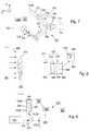
- FIG. 4Ais a simplified illustration of the WD feedback assembly 26 of FIGS. 1A and 1B in the first device position 40 A and the first angle of incidence ⁇ 1
- FIG. 4Billustrates the WD feedback assembly 26 in the second device position 40 B and the second angle of incidence ⁇ 2 .
- These Figuresalso illustrate the beam incident 12 A on the WD feedback assembly 26 , and the encoder marks 52 A and the optical reader 52 B of the position detector 28 .
- the motor 48has moved the grating 40 between the two positions 40 A, 40 B
- FIG. 5Ais a simplified illustration of another embodiment of a WD feedback assembly 526 in a first device position 540 A and the first angle of incidence ⁇ 1
- FIG. 5Billustrates the WD feedback assembly 526 in a second device position 540 B and the second angle of incidence ⁇ 2
- the beam 512 A incident on the WD feedback assembly 526is also illustrated in these Figures.
- the WD feedback assembly 526includes a plurality of feedback devices 540 (i.e.
- a multiple sided device housing 544that retains the feedback devices 540
- a rotary motor 548(illustrated as a box in phantom) that rotates the devices 540 and the device housing 544 about a rotation axis 546 .
- the number of feedback devices 540 used in this designcan be varied.
- the WD feedback assembly 526includes eight diffraction gratings 540 and the device housing 544 is octagonal shaped.
- this WD feedback assembly 526can include more than eight or fewer than eight gratings 540 .
- the number of gratings 540is increased, the number of spectral sweeps per motor revolution is increased.
- the WD feedback assembly 526could be designed with a single grating 540 .
- the lasermay only tuned over a five degree once per revolution of the grating 540 . This leads to a relatively low duty cycle for laser scanning.
- the rotary motor 548is a brushless DC servo motor. This type of motor is capable of (i) highly linear rotation, (ii) rotation speeds allowing one millisecond and faster scans over five degrees of grating rotation, and (ii) continuous operation with lifetimes of several years.
- control systemagain receives position signals from the position sensor 528 (illustrated as a box in phantom). Further, the control system can direct power pulses to the gain medium (not shown in FIGS. 5A and 5B ) at certain position signals, and not when the gratings 540 are at non-useful angles.
- FIG. 6Ais a simplified illustration of another embodiment of a WD feedback assembly 626 in a first device position 640 A and the first angle of incidence ⁇ 1
- FIG. 6Billustrates the WD feedback assembly 626 in a second device position 640 B and the second angle of incidence ⁇ 2
- the beam incident on the WD feedback assembly 626is also illustrated in these Figures.
- the WD feedback assembly 626includes a single stationary feedback device 640 (i.e. a grating), plurality of reflectors 641 (i.e.
- the reflectors 641sequentially direct the intracavity laser beam 612 A at the fixed grating 640 .
- This designmay be preferred over the embodiment illustrated in FIGS. 5A and 5B , since it may be easier to make a multi-faceted mirror than to align and attach multiple gratings to the device housing.
- the number of mirrors 641 used in this designcan be varied.
- the WD feedback assembly 626includes eight mirrors 641 and the device housing 644 is octagonal shaped.
- this WD feedback assembly 626can include more than eight or fewer than eight mirrors 641 .
- the rotary motor 648can again be a brushless DC servo motor.
- the control system(not shown in FIGS. 6A and 6B ) again receives position signals from the position sensor 628 (illustrated as a box in phantom). Further, the control system can direct power pulses to the gain medium (not shown in FIGS. 6A and 6B ) at certain position signals, and not when the mirrors 641 are at non-useful angles.
- FIG. 7is a simplified illustration of another embodiment of a laser source 710 that is somewhat similar to the laser source 10 described above.
- the laser source 710includes a gain medium 716 , a cavity optical assembly 718 , a power source 720 , a control system 730 , a mounting base 732 , a wavelength dependant (“WD”) feedback assembly 726 , and a position detector 728 that are somewhat similar to the corresponding components described above.
- the gain medium 716emits from only a first facet 716 A which is coated with an anti-reflection (AR) coating, a second facet 716 B of the gain medium 716 is coated with a high reflection (HR) coating, and the external cavity 736 is folded.
- the laser source 710includes a beam reflector 725 that directs a portion of the beam towards the WD feedback assembly 726 and allows a portion of the beam to pass there through as the output beam 712 .
- the beam reflector 725is a partly reflective output coupler that reflects a portion of the beam and allows a portion of the beam to transmit there through.
- the degree of reflectively of the beam reflector 725can be adjusted to optimize the output beam 712 .
- the degree of reflectivity of the beam reflector 725is optimized to optimize the tuning range and power of the laser source 710 .
- the beam reflector 725is a prism that requires only a coating on the surface that faces the gain medium 716 . This is because the residual reflection on the other surfaces of the prism will not feed back into the laser cavity 736 . It should be noted that in certain designs that the beam reflector 725 naturally produces two output beams 712 . Because many applications rely on picking off some of the output beam 712 to use for a reference channel, the two exiting beams 712 (having the same wavelength) allows a reference channel to be implemented without the inclusion of an additional beam splitter.
- the beamemits from the first facet 716 A along a first axis 795 and is directed along the first axis 795 at the beam reflector 725 . Subsequently, the beam reflector 725 redirects a portion of the beam along a second axis 796 at the WD feedback assembly 726 .
- the first axis 795 and the second axis 796are at an axis angle 797 of approximately 30°, 45°, 60°, 75°, or 90°relative to each other. It should be noted that other axis angles 797 can be utilized.
- the WD feedback assembly 726reflects a portion of the beam back to the gain medium 716 via the beam reflector 725 , and the WD feedback assembly 726 is used to precisely select and adjust the lasing frequency of the external cavity 736 and the wavelength of the output beams 712 .
- the WD feedback assembly 726dictates what wavelength will experience the most gain and thus dominate the wavelength of the output beams 712 .
- the WD feedback assembly 726is similar to the WD feedback assembly 26 illustrated in FIGS. 4A and 4B and described above.
- the WD feedback assembly 726can be similar to the corresponding WD feedback assemblies 526 , 626 illustrated in FIGS. 5A-6B .
- the gain medium 716 , the beam reflector 725 , and the WD feedback assembly 726cooperate to form the folded external cavity 736 .
- the folded configuration of the external cavity 736can allow for a relatively longer external cavity 736 in an overall relatively small footprint. This allows for a smaller physical dimensioned laser source 710 .
- longer cavity lengthse.g. approximately 10 centimeters
- the laser source 710does not require an output optical assembly 24 (illustrated in FIGS. 1A and 1B ). Stated in another fashion, because the gain medium 716 is emitting from only one facet 716 A, only one optical assembly 718 is required. This can reduce the cost and complexity of the laser source 710 .
- FIG. 8is simplified illustration of a gas sensor system 870 having features of the present invention and an emitting gas 872 .
- the gas sensor system 870includes (i) a laser source 810 that illuminates the area near the emitting gas 872 , and (ii) an imager 874 (i.e. an infrared camera) that captures real-time, high resolution thermal images 876 of the emitting gas 872 that can be displayed or recorded for future viewing.
- the gas sensor system 870is useful for locating emitting gas 872 (i.e. leaks) in the oil, gas, utility, chemical industries, as well as locating emitting gas 872 for homeland security.
- the gas sensor system 870can be extremely compact, hand-held, lightweight, stable, rugged, small, self-contained, and portable.
- the sensor system 870can have dimensions of approximately 130 millimeters (height) by 145 millimeters (width) by 250 millimeters (length) (where length is taken along the propagation direction of the laser beam) or less.
- the type of emitting gas 872 detectable by the sensor system 870can include any gas 872 having molecules that absorb (“absorption features”) in the MIR range.
- gases 872 having absorption features in the MIR range that can be detectedincludes, but is not limited to, (i) sulfur hexafluoride (SF6), (ii) Acetylchloride, (iii) Ethylene, (iv) Freon (such as dichlorodifluoromethane), (v) Propenal, (vii) Tricholorethylene, (viii) methane (CH4), (ix) ethylene (C2H4), (x) ethane (C2H6), (xi) hydrogen chloride (HCl), (xii) ammonia (NH3), (xiii) nitrous oxide (NO), (xiv) hydrazine (N2H4), and (xv) monomethyl hydrazine (MMH).
- gases 12includes (i) sulfur hexafluor
- a non-exclusive list of possible gas sources 878 of the emitting gas 872includes containers, power plants, industrial equipment, gas lines, storage tanks, and electrical equipment.
- the laser source 810can be similar in design to the laser sources 10 described above.
- the laser source 710can rapidly and accurately generate one or more sets of sequential, wavelength specific output beams 812 that span a predetermined detection range (e.g. the mid-infrared range).
- the imager 874captures the thermal image 876 of the emitting gas 872 and the surrounding environment.
- the imager 874is an infrared camera that provides real-time, high resolution thermal images 876 of the emitting gas 872 that can be displayed on a display 882 or recorded for future viewing.
- the display 882is illustrated as being positioned away from the imager 874 .
- the display 882can be a screen that is attached to the imager 874 .
- the imager 874includes an image sensor 884 (illustrated in phantom), a filter assembly 886 (illustrated in phantom), a storage system 888 (illustrated in phantom), and an imager control system 890 .
- the image sensor 884receives the light that passes through the filter assembly 786 and converts the light into electricity.
- suitable image sensors 884can include microbolometers, quantum well infrared photodetectors, or thermal light valve technology sold by Redshift Systems Corporation, located in Burlington, Mass.
- the filter assembly 886limits the wavelength of the light that is directed at the image sensor 884 .
- the filter assembly 886can be designed to transmit all light in the MIR range, and block all light having a wavelength that is greater or lesser than the MIR range. With this design, the image sensor 884 responds primarily to desired wavelength, and ignores other background thermal emissions.
- the storage system 7888stores the various images.
- suitable storage systems 888include flash memory, a floppy disk, a hard disk, or a writeable CD or DVD.
- the imager control system 890is electrically connected to and controls the operation of the electrical components of the imager 874 .
- the imager control system 790can include one or more processors and circuits and the imager control system 890 can be programmed to perform one or more of the functions described herein.
- the imager control system 890receives information from the image sensor 884 and generates the image 876 . Additionally, or alternatively, the imager control system 890 can further enhance the image 876 with color or other features that will further identify the location or type of emitting gas 872 .
- the imager control system 890can analyze the information from one or more images 876 to identify the one or more specific emitting gases 872 that are present and/or determine the quantity of one or more emitting gases 872 that are present.
- the imager 874 and the laser source 810share a common housing.
- the imager 874 and the laser source 810can have separate housings.
- the imager 874can include a battery 892 (illustrated in phantom) for powering the imager 874 . This allows for the portable operation of the imager 874 in remote locations.
- the imager 874 and the laser source 810can share a common battery, or the sensor system 870 can be connected with an electrical cord to a power outlet.
- the output beams 812are directed at a background 894 near a possible site of a gas leakage.
- the imager 874captures both backscattered light 896 (illustrated as arrows) that is reflected off of the background 894 and background radiation.
- the backscattered light 896is highly attenuated. This produces a region of contrast or shadow 898 on the image 876 that corresponds to and clearly illustrates the emitting gas 872 .
- the background 894can be any object that reflects the output beams 812 .
- the wavelength of the output beams 812is synchronized with the imager 874 so that imager control system 890 knows the wavelength of the output beam 812 at the time each image 876 is captured so that the gas 872 captured in the image 876 can be specifically identified. For example, if the gas 872 appears in a first image captured when the output beam 812 is at a first center wavelength and the gas 872 does not appear in a second image when the output beam 812 is at a second center wavelength, the type of gas 872 captured in the first image can be identified if the value of the first wavelength is known.
- the laser source 810can be controlled to generate a set of sequential, specific, different center wavelength output beams 812 that span a portion or the entire the MIR range.
- the imager control system 890can analyze the images 876 captured by the imager 874 and compare the images 876 to a lookup table (not shown) that includes the absorption profiles of the gases in interest. With this information, the imager control system 890 can identify the gases 872 detected and/or how much of each of the gases is present. Further, with this design, the sensor system 870 scans for a relatively large number of gases 872 that have absorption in the scanning range.
- FIG. 9is simplified illustration of another embodiment of a fluid sensor system having features of the present invention.
- the fluid sensor systemincludes a laser source 910 (similar to those described above) that generates a plurality of output beams 912 , and a spectrometer 970 that utilizes the output beams 912 to analyze one or more substance 972 (illustrated as circles).
- the substance 972can be a liquid, gas or solid.
- the spectrometer 970includes (i) a beam splitter 974 that splits the output beams 912 into two beams 912 A, 912 B, (ii) a reference detector 976 that receives one of the beams 912 A and that analyzes the beam 912 A to determine the unattenuated power level, (iii) a sample area 978 (e.g.
- a containerthat receives the other beam 912 B and the one or more gases 972 , (iv) a signal detector 980 (illustrated in phantom) that detects the beam 912 B after travelling through the sample area 978 , (v) control electronics 982 for powering the laser 910 and the spectrometer 970 , (vi) acquisition electronics 984 for digitizing and integrating the detector signals from the signal detector 980 , and (vii) analysis electronics 986 fro assembling the data into spectra and analyzing the spectra to determine the concentration and/or presence of different chemicals in the gases 972 .
- the sample area 978can be a container that receives the one or more substances 972 .
- the sample area 978can include an area input 978 A and an area output 978 B that allows the substances 972 to be changed in the sample area 978 .
- the sample area 978receives a gas or condensed phase sample in a cell, or a condensed phase sample in an attenuated-total-reflectance (ATR) device.
- ATRattenuated-total-reflectance
Landscapes
- Physics & Mathematics (AREA)
- Spectroscopy & Molecular Physics (AREA)
- General Physics & Mathematics (AREA)
- Chemical & Material Sciences (AREA)
- Pathology (AREA)
- Analytical Chemistry (AREA)
- Biochemistry (AREA)
- General Health & Medical Sciences (AREA)
- Health & Medical Sciences (AREA)
- Immunology (AREA)
- Life Sciences & Earth Sciences (AREA)
- Condensed Matter Physics & Semiconductors (AREA)
- Electromagnetism (AREA)
- Optics & Photonics (AREA)
- Lasers (AREA)
- Investigating Or Analysing Materials By Optical Means (AREA)
- Spectrometry And Color Measurement (AREA)
Abstract
Description
Claims (22)
Priority Applications (1)
| Application Number | Priority Date | Filing Date | Title |
|---|---|---|---|
| US12/960,742US8068521B2 (en) | 2008-01-17 | 2010-12-06 | Laser source that generates a plurality of alternative wavelength output beams |
Applications Claiming Priority (3)
| Application Number | Priority Date | Filing Date | Title |
|---|---|---|---|
| US2185408P | 2008-01-17 | 2008-01-17 | |
| US12/353,223US7848382B2 (en) | 2008-01-17 | 2009-01-13 | Laser source that generates a plurality of alternative wavelength output beams |
| US12/960,742US8068521B2 (en) | 2008-01-17 | 2010-12-06 | Laser source that generates a plurality of alternative wavelength output beams |
Related Parent Applications (1)
| Application Number | Title | Priority Date | Filing Date |
|---|---|---|---|
| US12/353,223ContinuationUS7848382B2 (en) | 2008-01-17 | 2009-01-13 | Laser source that generates a plurality of alternative wavelength output beams |
Publications (2)
| Publication Number | Publication Date |
|---|---|
| US20110096800A1 US20110096800A1 (en) | 2011-04-28 |
| US8068521B2true US8068521B2 (en) | 2011-11-29 |
Family
ID=40601443
Family Applications (2)
| Application Number | Title | Priority Date | Filing Date |
|---|---|---|---|
| US12/353,223Active2029-04-18US7848382B2 (en) | 2008-01-17 | 2009-01-13 | Laser source that generates a plurality of alternative wavelength output beams |
| US12/960,742ActiveUS8068521B2 (en) | 2008-01-17 | 2010-12-06 | Laser source that generates a plurality of alternative wavelength output beams |
Family Applications Before (1)
| Application Number | Title | Priority Date | Filing Date |
|---|---|---|---|
| US12/353,223Active2029-04-18US7848382B2 (en) | 2008-01-17 | 2009-01-13 | Laser source that generates a plurality of alternative wavelength output beams |
Country Status (2)
| Country | Link |
|---|---|
| US (2) | US7848382B2 (en) |
| EP (1) | EP2081265B1 (en) |
Cited By (15)
| Publication number | Priority date | Publication date | Assignee | Title |
|---|---|---|---|---|
| US8335413B2 (en) | 2010-05-14 | 2012-12-18 | Daylight Solutions, Inc. | Optical switch |
| US20130076274A1 (en)* | 2011-09-28 | 2013-03-28 | DigitalOptics Corporation MEMS | Electrostatic actuator control |
| US8774244B2 (en) | 2009-04-21 | 2014-07-08 | Daylight Solutions, Inc. | Thermal pointer |
| US9042688B2 (en) | 2011-01-26 | 2015-05-26 | Daylight Solutions, Inc. | Multiple port, multiple state optical switch |
| US9059562B2 (en) | 2011-06-23 | 2015-06-16 | Daylight Solutions, Inc. | Control system for directing power to a laser assembly |
| US9077137B2 (en) | 2013-03-08 | 2015-07-07 | Daylight Solutions, Inc. | Laser assembly with package beam pointing registration |
| US9086375B2 (en) | 2008-04-29 | 2015-07-21 | Daylight Solutions, Inc. | Laser source with a large spectral range |
| US9093813B2 (en) | 2011-10-11 | 2015-07-28 | Daylight Solutions, Inc. | Mounting base for a laser system |
| US9147995B2 (en) | 2013-03-15 | 2015-09-29 | Daylight Solutions, Inc. | Rapidly tunable laser source assembly with long stroke grating mover |
| US9496674B2 (en) | 2012-08-28 | 2016-11-15 | Daylight Solutions, Inc. | Rapidly tunable laser assembly |
| US9739661B2 (en) | 2015-06-30 | 2017-08-22 | Agilent Technologies, Inc. | Infrared imaging system with automatic referencing |
| US9791113B2 (en) | 2013-10-23 | 2017-10-17 | Daylight Solutions, Inc. | Light source assembly with multiple, disparate light sources |
| US10208902B2 (en) | 2013-10-23 | 2019-02-19 | Daylight Solutions, Inc. | Light source assembly with multiple, disparate light sources |
| US11009217B2 (en) | 2013-10-23 | 2021-05-18 | Daylight Solutions, Inc. | Light source assembly with multiple, disparate light sources |
| US20220412704A1 (en)* | 2014-05-23 | 2022-12-29 | Vista Outdoor Operations Llc | Handgun cartridge with shear groove bullet |
Families Citing this family (35)
| Publication number | Priority date | Publication date | Assignee | Title |
|---|---|---|---|---|
| US7492806B2 (en) | 2005-06-15 | 2009-02-17 | Daylight Solutions, Inc. | Compact mid-IR laser |
| US7535656B2 (en) | 2005-06-15 | 2009-05-19 | Daylight Solutions, Inc. | Lenses, optical sources, and their couplings |
| WO2009039683A1 (en) | 2007-09-28 | 2009-04-02 | Chongfei Shen | Infrared sensor, focal plane array and infrared imaging system thereof |
| US7848382B2 (en)* | 2008-01-17 | 2010-12-07 | Daylight Solutions, Inc. | Laser source that generates a plurality of alternative wavelength output beams |
| US8565275B2 (en) | 2008-04-29 | 2013-10-22 | Daylight Solutions, Inc. | Multi-wavelength high output laser source assembly with precision output beam |
| US20110255561A1 (en)* | 2008-07-14 | 2011-10-20 | The General Hospital Corporation | Apparatus configured to provide a wavelength-swept electro-magnetic radiation |
| EP2451033A4 (en)* | 2009-06-30 | 2013-01-09 | Shandong Fareach Optics Inc | Continuous mode-hop-free grating-tuned external cavity semiconductor laser |
| US8902944B2 (en)* | 2009-10-08 | 2014-12-02 | Kaiam Corp. | High power multi-wavelength laser source |
| US8718105B2 (en)* | 2010-03-15 | 2014-05-06 | Daylight Solutions, Inc. | Laser source that generates a rapidly changing output beam |
| US8269977B2 (en)* | 2010-05-26 | 2012-09-18 | Gerard A Alphonse | Discrete spectrum broadband optical source |
| US8259304B2 (en)* | 2010-05-26 | 2012-09-04 | Gerard A Alphonse | Broadband discrete spectrum optical source |
| US9225148B2 (en) | 2010-09-23 | 2015-12-29 | Daylight Solutions, Inc. | Laser source assembly with thermal control and mechanically stable mounting |
| US8467430B2 (en) | 2010-09-23 | 2013-06-18 | Daylight Solutions, Inc. | Continuous wavelength tunable laser source with optimum orientation of grating and gain medium |
| JP5775325B2 (en) | 2011-02-25 | 2015-09-09 | 浜松ホトニクス株式会社 | Tunable light source |
| US8730466B2 (en) | 2011-07-14 | 2014-05-20 | Thermo Electron Scientific Instruments Llc | Optical spectrometer with underfilled fiber optic sample interface |
| US9989412B2 (en)* | 2011-10-25 | 2018-06-05 | Daylight Solutions, Inc. | Low-noise spectroscopic imaging system |
| US10365158B2 (en)* | 2011-10-25 | 2019-07-30 | Daylight Solutions, Inc. | Low-noise spectroscopic imaging system |
| JP6313211B2 (en)* | 2011-10-25 | 2018-04-18 | デイライト ソリューションズ、インコーポレイテッド | Infrared imaging microscope |
| DE102012006047B3 (en)* | 2012-03-27 | 2013-08-01 | Deutsches Zentrum Für Luft- Und Raumfahrt | Device for determining gas concentrations in investigation volume e.g. clean room used in semiconductor manufacture, has beam steering unit that steers beam from radiation source on spectrometer over beam paths between deflection units |
| US11803044B2 (en) | 2014-01-18 | 2023-10-31 | Daylight Solutions, Inc. | Low-noise spectroscopic imaging system with steerable substantially coherent illumination |
| DE102014201701B4 (en)* | 2014-01-30 | 2018-04-05 | Fraunhofer-Gesellschaft zur Förderung der angewandten Forschung e.V. | Microelectromechanical system for tuning lasers |
| US20150311665A1 (en)* | 2014-04-29 | 2015-10-29 | Board Of Regents, The University Of Texas System | External cavity system generating broadly tunable terahertz radiation in mid-infrared quantum cascade lasers |
| CN107078457A (en)* | 2014-10-28 | 2017-08-18 | 住友电气工业株式会社 | Optical module applying light source, light modulator and wavelength detector and assembly method thereof |
| US10078014B2 (en)* | 2014-12-12 | 2018-09-18 | Daylight Solutions, Inc. | System and method for rapid thermal data acquisition |
| KR102469618B1 (en)* | 2015-03-23 | 2022-11-21 | 아이피지 포토닉스 코포레이션 | High Power CW Mid-IR Laser |
| US9312701B1 (en) | 2015-07-16 | 2016-04-12 | Wi-Charge Ltd | System for optical wireless power supply |
| KR102455846B1 (en)* | 2016-03-14 | 2022-10-18 | 위-차지 리미티드. | Systems for Optical Wireless Power Supplies |
| CN109937359A (en)* | 2016-09-15 | 2019-06-25 | 前视红外系统股份公司 | Gas detection on scene |
| WO2018075964A1 (en)* | 2016-10-21 | 2018-04-26 | Rebellion Photonics, Inc. | Mobile gas and chemical imaging camera |
| JP6943675B2 (en)* | 2017-08-10 | 2021-10-06 | 浜松ホトニクス株式会社 | External resonance type laser module, analyzer, external resonance type laser module drive method, program |
| KR102168373B1 (en)* | 2019-05-24 | 2020-10-22 | 세종대학교산학협력단 | Wireless optical charging system and method |
| JP7489277B2 (en)* | 2020-09-15 | 2024-05-23 | 浜松ホトニクス株式会社 | External Cavity Laser Module |
| JP7564014B2 (en)* | 2021-02-24 | 2024-10-08 | 浜松ホトニクス株式会社 | External Cavity Laser Module |
| US20230071683A1 (en)* | 2021-09-03 | 2023-03-09 | Thomas James Kane | Laser resonator assembly |
| JP7714420B2 (en)* | 2021-09-21 | 2025-07-29 | 浜松ホトニクス株式会社 | External Cavity Laser Module |
Citations (128)
| Publication number | Priority date | Publication date | Assignee | Title |
|---|---|---|---|---|
| US2684015A (en) | 1950-04-27 | 1954-07-20 | Polaroid Corp | Reflecting mirror optical objective |
| JPS5587107A (en) | 1978-12-23 | 1980-07-01 | Fujitsu Ltd | Photo switch |
| US4470662A (en) | 1983-04-07 | 1984-09-11 | Mid-West Instrument | Rotary optic switch |
| US4555627A (en) | 1983-04-05 | 1985-11-26 | The United States Of America As Represented By The United States Department Of Energy | Backscatter absorption gas imaging system |
| US4656641A (en) | 1985-02-04 | 1987-04-07 | Xerox Corporation | Laser cavity optical system for stabilizing the beam from a phase locked multi-emitter broad emitter laser |
| US4737028A (en) | 1986-04-07 | 1988-04-12 | The United States Of America As Represented By The Secretary Of The Army | Target loop active boresighting device |
| US4745276A (en) | 1985-03-08 | 1988-05-17 | Preussag Aktiengesellschaft Metall | Device for the detection of fluorescent substances on the surface of the earth |
| US4772789A (en) | 1987-12-28 | 1988-09-20 | Rockwell International Corporation | Leak imaging using differential absorption |
| US4796266A (en) | 1987-12-21 | 1989-01-03 | Bell Communications Research, Inc. | Laser driver circuit with dynamic bias |
| US4852956A (en) | 1986-12-15 | 1989-08-01 | Holotek Ltd. | Hologan scanner system |
| US4871916A (en) | 1987-05-08 | 1989-10-03 | The Broken Hill Proprietary Company Limited | Sensing of methane |
| US5005934A (en) | 1989-07-11 | 1991-04-09 | Galileo Electro-Optics Corporation | Fiber optics channel selection device |
| US5050176A (en) | 1989-06-19 | 1991-09-17 | Fujitsu Limited | Direct modulation phase-shift-keying system and method |
| US5064988A (en) | 1990-04-19 | 1991-11-12 | Havis-Shields Equipment Corporation | Laser light attachment for firearms |
| US5068867A (en) | 1989-11-20 | 1991-11-26 | Hughes Aircraft Company | Coupled quantum well strained superlattice structure and optically bistable semiconductor laser incorporating the same |
| US5082339A (en) | 1988-07-11 | 1992-01-21 | Telefunken Electronic Gmbh | Optical read-write head with diffraction grating structure |
| US5082799A (en) | 1990-09-14 | 1992-01-21 | Gte Laboratories Incorporated | Method for fabricating indium phosphide/indium gallium arsenide phosphide buried heterostructure semiconductor lasers |
| US5140599A (en) | 1990-08-01 | 1992-08-18 | Hewlett-Packard Company | Optical oscillator sweeper |
| US5161408A (en) | 1991-08-26 | 1992-11-10 | Mcrae Thomas G | Photo-acoustic leak detection system and method |
| WO1992020127A1 (en) | 1991-05-08 | 1992-11-12 | Radians Innova Ab | External cavity laser |
| US5172390A (en) | 1989-04-20 | 1992-12-15 | Massachusetts Institute Of Technology | Pre-aligned diode laser for external cavity operation |
| US5181214A (en) | 1991-11-18 | 1993-01-19 | Harmonic Lightwaves, Inc. | Temperature stable solid-state laser package |
| US5225679A (en) | 1992-01-24 | 1993-07-06 | Boston Advanced Technologies, Inc. | Methods and apparatus for determining hydrocarbon fuel properties |
| US5255073A (en) | 1989-05-19 | 1993-10-19 | Opsis Ab | Apparatus for emitting and receiving light |
| US5264368A (en) | 1990-10-10 | 1993-11-23 | Boston Advanced Technologies, Inc. | Hydrocarbon leak sensor |
| US5315436A (en) | 1990-06-06 | 1994-05-24 | Lowenhar Herman Leonard | Fiber optics system |
| US5331651A (en) | 1992-01-24 | 1994-07-19 | Hewlett-Packard Company | Method and apparatus for adjusting the wavelength in an optical device and laser using the method |
| US5430293A (en) | 1991-10-08 | 1995-07-04 | Osaka Gas Co., Ltd. | Gas visualizing apparatus and method for detecting gas leakage from tanks or piping |
| GB2286901A (en) | 1994-02-25 | 1995-08-30 | Perkin Elmer Corp | Optical switching apparatus using movable retroreflector |
| US5457709A (en) | 1994-04-04 | 1995-10-10 | At&T Ipm Corp. | Unipolar semiconductor laser |
| US5491714A (en)* | 1994-02-28 | 1996-02-13 | Ando Electric Co., Ltd. | Wavelength-variable semiconductor laser light source |
| US5523569A (en) | 1993-06-30 | 1996-06-04 | Stn Atlas Electronik Gmbh | Apparatus for detecting leakages in structural members |
| US5537432A (en) | 1993-01-07 | 1996-07-16 | Sdl, Inc. | Wavelength-stabilized, high power semiconductor laser |
| US5656813A (en) | 1995-04-04 | 1997-08-12 | Gmd Systems, Inc. | Apparatus for imaging gas |
| US5662819A (en) | 1994-02-10 | 1997-09-02 | Sony Corporation | Plasma processing method with controlled ion/radical ratio |
| US5751830A (en) | 1995-05-24 | 1998-05-12 | Lockheed Martin Energy Systems, Inc. | Method and apparatus for coherent imaging of infrared energy |
| US5752100A (en) | 1996-01-26 | 1998-05-12 | Eastman Kodak Company | Driver circuit for a camera autofocus laser diode with provision for fault protection |
| US5780724A (en) | 1997-03-27 | 1998-07-14 | United Technologies Corp | Photo-acoustic leak detector with improved signal-to-noise response |
| US5824884A (en) | 1997-03-27 | 1998-10-20 | United Technologies Corporation | Photo-acoustic leak detector with baseline measuring |
| EP0877454A1 (en) | 1997-05-07 | 1998-11-11 | Lucent Technologies Inc. | Article comprising an improved QC laser |
| EP0883220A2 (en) | 1997-06-06 | 1998-12-09 | Ando Electric Co., Ltd. | External resonator type of wavelength tunable semiconductor laser light source and method for tuning wavelength therefor |
| US5854422A (en) | 1996-07-10 | 1998-12-29 | K-Line Industries, Inc. | Ultrasonic detector |
| US5862162A (en) | 1996-03-25 | 1999-01-19 | Ando Electric Co., Ltd. | External resonator type wavelength- tunable light source |
| US5866073A (en) | 1997-02-28 | 1999-02-02 | The United States Of America As Represented By The Secretary Of The Army | Detector of halogenated compounds based on laser photofragmentation/fragment stimulated emission |
| US6089076A (en) | 1998-09-18 | 2000-07-18 | United Technologies Corporation | System to control the power of a beam |
| US6134257A (en) | 1998-04-21 | 2000-10-17 | Lucent Technologies Inc. | Solid state laser for operation in librational modes |
| US6154307A (en) | 1998-09-18 | 2000-11-28 | United Technologies Corporation | Method and apparatus to diffract multiple beams |
| US6157033A (en) | 1998-05-18 | 2000-12-05 | Power Distribution Services, Inc. | Leak detection system |
| US6192064B1 (en) | 1997-07-01 | 2001-02-20 | Cymer, Inc. | Narrow band laser with fine wavelength control |
| US6243404B1 (en) | 1999-01-25 | 2001-06-05 | Lucent Technologies, Inc. | Laser module with adjustable operating temperature range |
| US6326646B1 (en) | 1999-11-24 | 2001-12-04 | Lucent Technologies, Inc. | Mounting technology for intersubband light emitters |
| US20020024979A1 (en) | 1999-02-19 | 2002-02-28 | Kennet Vilhelmsson | Device and method for tuning the wavelength of the light in an external cavity laser |
| US20020064198A1 (en) | 2000-11-27 | 2002-05-30 | Hideshi Koizumi | Semiconductor laser device having a circuit for protecting semiconductor laser element from static electricity |
| US6400744B1 (en) | 2000-02-25 | 2002-06-04 | Lucent Technologies, Inc. | Apparatus comprising a quantum cascade laser having improved distributed feedback for single-mode operation |
| US20020090013A1 (en) | 2001-01-09 | 2002-07-11 | Murry Stefan J. | VCSEL assembly with edge-receiving optical devices |
| US20020105699A1 (en) | 2001-02-02 | 2002-08-08 | Teravicta Technologies, Inc | Integrated optical micro-electromechanical systems and methods of fabricating and operating the same |
| US20020150133A1 (en) | 1999-02-04 | 2002-10-17 | Takeshi Aikiyo | Mounting structure for semiconductor laser module |
| US6470036B1 (en) | 2000-11-03 | 2002-10-22 | Cidra Corporation | Tunable external cavity semiconductor laser incorporating a tunable bragg grating |
| US6483978B1 (en) | 2001-06-08 | 2002-11-19 | Photon-X, Inc. | Compact optical amplifier module |
| US20020176473A1 (en) | 2001-05-23 | 2002-11-28 | Aram Mooradian | Wavelength selectable, controlled chirp, semiconductor laser |
| US20030043877A1 (en) | 2001-09-04 | 2003-03-06 | Ron Kaspi | Multiple wavelength broad bandwidth optically pumped semiconductor laser |
| US20030063633A1 (en) | 2001-09-28 | 2003-04-03 | Zhang Guangzhi Z. | Tunable laser with suppression of spontaneous emission |
| US20030095346A1 (en) | 2001-10-31 | 2003-05-22 | The Furukawa Electric Co., Ltd. | Optical module |
| US6575641B2 (en) | 2000-11-13 | 2003-06-10 | Sumitomo Electric Industries, Ltd. | Laser diode module |
| US20030123495A1 (en) | 2001-12-31 | 2003-07-03 | Cox James Allen | Tunable laser assembly |
| WO2003067720A2 (en) | 2002-02-08 | 2003-08-14 | Fraunhofer-Gesellschaft zur Förderung der angewandten Forschung e.V. | Laser device comprising a quantum cascade laser |
| US20030174315A1 (en) | 2002-03-14 | 2003-09-18 | Byren Robert W. | Efficient multiple emitter boresight reference source |
| US20030179789A1 (en) | 2001-07-24 | 2003-09-25 | Pilgrim Jeffrey S. | Discrete wavelength-locked external cavity laser |
| US6636539B2 (en) | 2001-05-25 | 2003-10-21 | Novalux, Inc. | Method and apparatus for controlling thermal variations in an optical device |
| US20030198274A1 (en) | 2002-04-20 | 2003-10-23 | Lucchetti Richard L. | Laser-based jaw setting device |
| US20040013154A1 (en) | 2002-07-16 | 2004-01-22 | Applied Optoelectronics, Inc. | Optically-pumped multiple-quantum well active region with improved distribution of optical pumping power |
| US6690472B2 (en) | 2000-09-28 | 2004-02-10 | Sandia National Laboratories | Pulsed laser linescanner for a backscatter absorption gas imaging system |
| US20040032891A1 (en) | 2001-03-16 | 2004-02-19 | The Furukawa Electric Co., Ltd. | Light source having plural laser diode modules |
| US20040095579A1 (en) | 2002-11-19 | 2004-05-20 | Bisson Scott E. | Tunable light source for use in photoacoustic spectrometers |
| US6782162B2 (en) | 2001-08-06 | 2004-08-24 | Nippon Sheet Glass Co., Ltd. | Optical module and method for assembling the same |
| US20040165640A1 (en) | 2003-02-25 | 2004-08-26 | Clifford George M. | Apparatus and method for adjusting external-cavity lasers |
| US6803577B2 (en) | 1999-12-28 | 2004-10-12 | Gas Optics Sweden Ab | Quantitative imaging of gas emissions utilizing optical techniques |
| US20040208602A1 (en) | 2001-12-01 | 2004-10-21 | James Plante | Free space optical communications link tolerant of atmospheric interference |
| US20040228371A1 (en) | 2003-04-09 | 2004-11-18 | James Kolodzey | Terahertz frequency radiation sources and detectors based on group IV materials and method of manufacture |
| US20040238811A1 (en) | 2002-06-28 | 2004-12-02 | Takao Nakamura | Semiconductor light-emitting device |
| US20040264523A1 (en) | 2003-06-30 | 2004-12-30 | Posamentier Joshua D | Temperature compensation circuit to maintain ratio of monitor photodiode current to fiber coupled light in a laser |
| US6856717B2 (en) | 2003-03-24 | 2005-02-15 | Hymite A/S | Package with a light emitting device |
| US6866089B2 (en) | 2002-07-02 | 2005-03-15 | Carrier Corporation | Leak detection with thermal imaging |
| US20050083568A1 (en) | 2001-07-02 | 2005-04-21 | The Furukawa Electric Co., Ltd. | Semiconductor laser module, optical amplifier, and method of manufacturing the semiconductor laser module |
| US6885965B2 (en) | 2002-05-22 | 2005-04-26 | First Responder Systems Technologies, Llc | Processing system for remote chemical identification |
| US20050105566A1 (en) | 2003-11-19 | 2005-05-19 | Joachim Sacher | Laser diode arrangement with external resonator |
| US6909539B2 (en) | 2000-08-30 | 2005-06-21 | Science Applications International Corporation | System and method for combining multiple energy bands to improve scene viewing |
| US20050199869A1 (en) | 2004-02-05 | 2005-09-15 | Zhisheng Shi | Orientated group IV-VI semiconductor structure, and method for making and using the same |
| US20050213627A1 (en) | 2004-02-20 | 2005-09-29 | Humboldt-Universtaet Zu Berlin | Quantum cascade laser structure |
| US20050237524A1 (en) | 2004-03-01 | 2005-10-27 | National Institute Of Adv. Industrial Sci. & Tech. | Device for detecting emission light of micro-object |
| JP2005317819A (en) | 2004-04-30 | 2005-11-10 | Sony Corp | Laser system |
| US6995846B2 (en) | 2003-12-19 | 2006-02-07 | Itt Manufacturing Enterprises, Inc. | System and method for remote quantitative detection of fluid leaks from a natural gas or oil pipeline |
| US20060056466A1 (en) | 2004-08-19 | 2006-03-16 | Gregory Belenky | Semiconductor light source with electrically tunable emission wavelength |
| US7032431B2 (en) | 2003-06-13 | 2006-04-25 | Baum Marc A | Non-invasive, miniature, breath monitoring apparatus |
| US7061022B1 (en) | 2003-08-26 | 2006-06-13 | United States Of America As Represented By The Secretary Of The Army | Lateral heat spreading layers for epi-side up ridge waveguide semiconductor lasers |
| US7088076B2 (en) | 2000-09-21 | 2006-08-08 | O2Micro International Limited | Power management for battery powered appliances |
| US20060214107A1 (en) | 2005-03-22 | 2006-09-28 | Mueller Eric R | Detection of hidden objects by terahertz heterodyne laser imaging |
| US20060262316A1 (en) | 2005-05-20 | 2006-11-23 | Baney Douglas M | System and method for interferometric laser photoacoustic spectroscopy |
| US20060268947A1 (en) | 2005-05-24 | 2006-11-30 | Itt Manufacturing Enterprises, Inc. | Multi-line tunable laser system |
| US7151787B2 (en) | 2003-09-10 | 2006-12-19 | Sandia National Laboratories | Backscatter absorption gas imaging systems and light sources therefore |
| US20070019702A1 (en) | 2005-06-15 | 2007-01-25 | Daylight Solutions Inc. | Lenses, optical sources, and their couplings |
| US20070030865A1 (en) | 2005-08-05 | 2007-02-08 | Daylight Solutions | External cavity tunable compact mid-IR laser |
| US20070047599A1 (en) | 2005-08-15 | 2007-03-01 | William Marsh Rice University | Piezo activated mode tracking system for widely tunable mode-hop-free external cavity mid-IR semiconductor lasers |
| US7189970B2 (en) | 2003-08-29 | 2007-03-13 | Power Diagnostic Technologies Ltd. | Imaging of fugitive gas leaks |
| US20070195833A1 (en)* | 2003-09-29 | 2007-08-23 | Bernd Nebendahl | Angular laser control |
| US7265842B2 (en) | 2004-10-14 | 2007-09-04 | Picarro, Inc. | Method for detecting a gaseous analyte present as a minor constituent in an admixture |
| US20070291804A1 (en) | 2005-06-15 | 2007-12-20 | Timothy Day | Compact mid-IR laser |
| US7345277B2 (en) | 2000-08-09 | 2008-03-18 | Evan Zhang | Image intensifier and LWIR fusion/combination system |
| WO2008036884A2 (en) | 2006-09-22 | 2008-03-27 | Daylight Solutions, Inc. | Compact external cavity mid-ir optical lasers |
| WO2008036881A2 (en) | 2006-09-22 | 2008-03-27 | Daylight Solutions, Inc. | Extended tuning in external cavity quantum cascade lasers |
| US20080075153A1 (en) | 2000-06-12 | 2008-03-27 | Time Domain Corporation | Method and apparatus for applying codes having pre-defined properties |
| US7358498B2 (en) | 2003-08-04 | 2008-04-15 | Technest Holdings, Inc. | System and a method for a smart surveillance system |
| US20080231719A1 (en) | 2007-03-23 | 2008-09-25 | Flir Systems Inc. | Thermography camera configured for leak detection |
| US7429734B1 (en) | 2006-11-29 | 2008-09-30 | Aculight Corporation | System and method for aircraft infrared countermeasures to missiles |
| US20080304524A1 (en) | 2007-03-12 | 2008-12-11 | Daylight Solutions, Inc. | Quantum cascade laser suitable for portable applications |
| US20090015914A1 (en) | 2007-07-10 | 2009-01-15 | Lockheed Martin Corporation A Maryland Corporation | Scanning wide field telescope and method |
| US20090159798A1 (en) | 2007-12-20 | 2009-06-25 | Daylight Solutions, Inc. | Gas imaging system |
| US20090213882A1 (en) | 2008-01-17 | 2009-08-27 | Miles James Weida | Laser source that generates a plurality of alternative wavelength output beams |
| US7590316B2 (en) | 2005-09-14 | 2009-09-15 | Polatis Limited | Optical switch |
| US20090257709A1 (en) | 2004-07-15 | 2009-10-15 | Polatis Ltd. | Optical switch |
| US7623234B2 (en) | 2004-03-22 | 2009-11-24 | Quantaspec, Inc. | System and method for detecting and identifying an analyte |
| US20100110198A1 (en) | 2008-04-01 | 2010-05-06 | Daylight Solutions, Inc. | Mid infrared optical illuminator assembly |
| US7733925B2 (en) | 2008-07-07 | 2010-06-08 | Daylight Solutions, Inc. | Continuous wavelength tunable laser source with optimum positioning of pivot axis for grating |
| US7732767B2 (en) | 2006-08-11 | 2010-06-08 | Lasermax, Inc. | Target marker having quantum cascade laser for thermally marking a target |
| US7755041B2 (en) | 2005-11-15 | 2010-07-13 | University Of South Florida | Optical and laser differential absorption remote detection of TATP peroxide based explosives |
| US20100229448A1 (en) | 2007-12-14 | 2010-09-16 | Lasermax, Inc. | Removable foregrip with laser sight |
| US20100243891A1 (en) | 2005-06-15 | 2010-09-30 | Timothy Day | Compact mid-ir laser |
| US7818911B2 (en) | 2007-10-26 | 2010-10-26 | Lasermax, Inc. | Target marking system having a gas laser assembly and a thermal imager |
Family Cites Families (2)
| Publication number | Priority date | Publication date | Assignee | Title |
|---|---|---|---|---|
| JPH0724322B2 (en) | 1989-07-17 | 1995-03-15 | 松下電器産業株式会社 | Optical feedback type light emitting device |
| GB2382848A (en) | 2001-12-06 | 2003-06-11 | Alstom | Gas turbine wet compression |
- 2009
- 2009-01-13USUS12/353,223patent/US7848382B2/enactiveActive
- 2009-01-15EPEP09150631.1Apatent/EP2081265B1/enactiveActive
- 2010
- 2010-12-06USUS12/960,742patent/US8068521B2/enactiveActive
Patent Citations (149)
| Publication number | Priority date | Publication date | Assignee | Title |
|---|---|---|---|---|
| US2684015A (en) | 1950-04-27 | 1954-07-20 | Polaroid Corp | Reflecting mirror optical objective |
| JPS5587107A (en) | 1978-12-23 | 1980-07-01 | Fujitsu Ltd | Photo switch |
| US4555627A (en) | 1983-04-05 | 1985-11-26 | The United States Of America As Represented By The United States Department Of Energy | Backscatter absorption gas imaging system |
| US4470662A (en) | 1983-04-07 | 1984-09-11 | Mid-West Instrument | Rotary optic switch |
| US4656641A (en) | 1985-02-04 | 1987-04-07 | Xerox Corporation | Laser cavity optical system for stabilizing the beam from a phase locked multi-emitter broad emitter laser |
| US4745276A (en) | 1985-03-08 | 1988-05-17 | Preussag Aktiengesellschaft Metall | Device for the detection of fluorescent substances on the surface of the earth |
| US4737028A (en) | 1986-04-07 | 1988-04-12 | The United States Of America As Represented By The Secretary Of The Army | Target loop active boresighting device |
| US4852956A (en) | 1986-12-15 | 1989-08-01 | Holotek Ltd. | Hologan scanner system |
| US4871916A (en) | 1987-05-08 | 1989-10-03 | The Broken Hill Proprietary Company Limited | Sensing of methane |
| US4796266A (en) | 1987-12-21 | 1989-01-03 | Bell Communications Research, Inc. | Laser driver circuit with dynamic bias |
| US4772789A (en) | 1987-12-28 | 1988-09-20 | Rockwell International Corporation | Leak imaging using differential absorption |
| US5082339A (en) | 1988-07-11 | 1992-01-21 | Telefunken Electronic Gmbh | Optical read-write head with diffraction grating structure |
| US5172390A (en) | 1989-04-20 | 1992-12-15 | Massachusetts Institute Of Technology | Pre-aligned diode laser for external cavity operation |
| US5255073A (en) | 1989-05-19 | 1993-10-19 | Opsis Ab | Apparatus for emitting and receiving light |
| US5050176A (en) | 1989-06-19 | 1991-09-17 | Fujitsu Limited | Direct modulation phase-shift-keying system and method |
| US5005934A (en) | 1989-07-11 | 1991-04-09 | Galileo Electro-Optics Corporation | Fiber optics channel selection device |
| US5068867A (en) | 1989-11-20 | 1991-11-26 | Hughes Aircraft Company | Coupled quantum well strained superlattice structure and optically bistable semiconductor laser incorporating the same |
| US5064988A (en) | 1990-04-19 | 1991-11-12 | Havis-Shields Equipment Corporation | Laser light attachment for firearms |
| US5315436A (en) | 1990-06-06 | 1994-05-24 | Lowenhar Herman Leonard | Fiber optics system |
| US5140599A (en) | 1990-08-01 | 1992-08-18 | Hewlett-Packard Company | Optical oscillator sweeper |
| US5082799A (en) | 1990-09-14 | 1992-01-21 | Gte Laboratories Incorporated | Method for fabricating indium phosphide/indium gallium arsenide phosphide buried heterostructure semiconductor lasers |
| US5264368A (en) | 1990-10-10 | 1993-11-23 | Boston Advanced Technologies, Inc. | Hydrocarbon leak sensor |
| WO1992020127A1 (en) | 1991-05-08 | 1992-11-12 | Radians Innova Ab | External cavity laser |
| US5161408A (en) | 1991-08-26 | 1992-11-10 | Mcrae Thomas G | Photo-acoustic leak detection system and method |
| US5430293A (en) | 1991-10-08 | 1995-07-04 | Osaka Gas Co., Ltd. | Gas visualizing apparatus and method for detecting gas leakage from tanks or piping |
| US5181214A (en) | 1991-11-18 | 1993-01-19 | Harmonic Lightwaves, Inc. | Temperature stable solid-state laser package |
| US5331651A (en) | 1992-01-24 | 1994-07-19 | Hewlett-Packard Company | Method and apparatus for adjusting the wavelength in an optical device and laser using the method |
| US5225679A (en) | 1992-01-24 | 1993-07-06 | Boston Advanced Technologies, Inc. | Methods and apparatus for determining hydrocarbon fuel properties |
| US5537432A (en) | 1993-01-07 | 1996-07-16 | Sdl, Inc. | Wavelength-stabilized, high power semiconductor laser |
| US5523569A (en) | 1993-06-30 | 1996-06-04 | Stn Atlas Electronik Gmbh | Apparatus for detecting leakages in structural members |
| US5662819A (en) | 1994-02-10 | 1997-09-02 | Sony Corporation | Plasma processing method with controlled ion/radical ratio |
| GB2286901A (en) | 1994-02-25 | 1995-08-30 | Perkin Elmer Corp | Optical switching apparatus using movable retroreflector |
| US5491714A (en)* | 1994-02-28 | 1996-02-13 | Ando Electric Co., Ltd. | Wavelength-variable semiconductor laser light source |
| US5457709A (en) | 1994-04-04 | 1995-10-10 | At&T Ipm Corp. | Unipolar semiconductor laser |
| US5656813A (en) | 1995-04-04 | 1997-08-12 | Gmd Systems, Inc. | Apparatus for imaging gas |
| US5751830A (en) | 1995-05-24 | 1998-05-12 | Lockheed Martin Energy Systems, Inc. | Method and apparatus for coherent imaging of infrared energy |
| US5752100A (en) | 1996-01-26 | 1998-05-12 | Eastman Kodak Company | Driver circuit for a camera autofocus laser diode with provision for fault protection |
| US5862162A (en) | 1996-03-25 | 1999-01-19 | Ando Electric Co., Ltd. | External resonator type wavelength- tunable light source |
| US5854422A (en) | 1996-07-10 | 1998-12-29 | K-Line Industries, Inc. | Ultrasonic detector |
| US5866073A (en) | 1997-02-28 | 1999-02-02 | The United States Of America As Represented By The Secretary Of The Army | Detector of halogenated compounds based on laser photofragmentation/fragment stimulated emission |
| US5780724A (en) | 1997-03-27 | 1998-07-14 | United Technologies Corp | Photo-acoustic leak detector with improved signal-to-noise response |
| US5834632A (en) | 1997-03-27 | 1998-11-10 | United Technologies Corporation | Photo-acoustic leak detector with multiple beams |
| US5824884A (en) | 1997-03-27 | 1998-10-20 | United Technologies Corporation | Photo-acoustic leak detector with baseline measuring |
| EP0877454A1 (en) | 1997-05-07 | 1998-11-11 | Lucent Technologies Inc. | Article comprising an improved QC laser |
| EP0883220A2 (en) | 1997-06-06 | 1998-12-09 | Ando Electric Co., Ltd. | External resonator type of wavelength tunable semiconductor laser light source and method for tuning wavelength therefor |
| US6192064B1 (en) | 1997-07-01 | 2001-02-20 | Cymer, Inc. | Narrow band laser with fine wavelength control |
| US6134257A (en) | 1998-04-21 | 2000-10-17 | Lucent Technologies Inc. | Solid state laser for operation in librational modes |
| US6157033A (en) | 1998-05-18 | 2000-12-05 | Power Distribution Services, Inc. | Leak detection system |
| US6154307A (en) | 1998-09-18 | 2000-11-28 | United Technologies Corporation | Method and apparatus to diffract multiple beams |
| US6089076A (en) | 1998-09-18 | 2000-07-18 | United Technologies Corporation | System to control the power of a beam |
| US6327896B1 (en) | 1998-09-18 | 2001-12-11 | United Technologies Corporation | Photo-acoustic leak detection system |
| US6243404B1 (en) | 1999-01-25 | 2001-06-05 | Lucent Technologies, Inc. | Laser module with adjustable operating temperature range |
| US20020150133A1 (en) | 1999-02-04 | 2002-10-17 | Takeshi Aikiyo | Mounting structure for semiconductor laser module |
| US20020024979A1 (en) | 1999-02-19 | 2002-02-28 | Kennet Vilhelmsson | Device and method for tuning the wavelength of the light in an external cavity laser |
| US6326646B1 (en) | 1999-11-24 | 2001-12-04 | Lucent Technologies, Inc. | Mounting technology for intersubband light emitters |
| US6803577B2 (en) | 1999-12-28 | 2004-10-12 | Gas Optics Sweden Ab | Quantitative imaging of gas emissions utilizing optical techniques |
| US6400744B1 (en) | 2000-02-25 | 2002-06-04 | Lucent Technologies, Inc. | Apparatus comprising a quantum cascade laser having improved distributed feedback for single-mode operation |
| US20080075153A1 (en) | 2000-06-12 | 2008-03-27 | Time Domain Corporation | Method and apparatus for applying codes having pre-defined properties |
| US7345277B2 (en) | 2000-08-09 | 2008-03-18 | Evan Zhang | Image intensifier and LWIR fusion/combination system |
| US6909539B2 (en) | 2000-08-30 | 2005-06-21 | Science Applications International Corporation | System and method for combining multiple energy bands to improve scene viewing |
| US7088076B2 (en) | 2000-09-21 | 2006-08-08 | O2Micro International Limited | Power management for battery powered appliances |
| US6690472B2 (en) | 2000-09-28 | 2004-02-10 | Sandia National Laboratories | Pulsed laser linescanner for a backscatter absorption gas imaging system |
| US6470036B1 (en) | 2000-11-03 | 2002-10-22 | Cidra Corporation | Tunable external cavity semiconductor laser incorporating a tunable bragg grating |
| US6575641B2 (en) | 2000-11-13 | 2003-06-10 | Sumitomo Electric Industries, Ltd. | Laser diode module |
| US20020064198A1 (en) | 2000-11-27 | 2002-05-30 | Hideshi Koizumi | Semiconductor laser device having a circuit for protecting semiconductor laser element from static electricity |
| US20020090013A1 (en) | 2001-01-09 | 2002-07-11 | Murry Stefan J. | VCSEL assembly with edge-receiving optical devices |
| US20020105699A1 (en) | 2001-02-02 | 2002-08-08 | Teravicta Technologies, Inc | Integrated optical micro-electromechanical systems and methods of fabricating and operating the same |
| US20040032891A1 (en) | 2001-03-16 | 2004-02-19 | The Furukawa Electric Co., Ltd. | Light source having plural laser diode modules |
| US20020176473A1 (en) | 2001-05-23 | 2002-11-28 | Aram Mooradian | Wavelength selectable, controlled chirp, semiconductor laser |
| US6636539B2 (en) | 2001-05-25 | 2003-10-21 | Novalux, Inc. | Method and apparatus for controlling thermal variations in an optical device |
| US6483978B1 (en) | 2001-06-08 | 2002-11-19 | Photon-X, Inc. | Compact optical amplifier module |
| US20050083568A1 (en) | 2001-07-02 | 2005-04-21 | The Furukawa Electric Co., Ltd. | Semiconductor laser module, optical amplifier, and method of manufacturing the semiconductor laser module |
| US20030179789A1 (en) | 2001-07-24 | 2003-09-25 | Pilgrim Jeffrey S. | Discrete wavelength-locked external cavity laser |
| US6782162B2 (en) | 2001-08-06 | 2004-08-24 | Nippon Sheet Glass Co., Ltd. | Optical module and method for assembling the same |
| US6553045B2 (en) | 2001-09-04 | 2003-04-22 | The United States Of America As Represented By The Secretary Of The Air Force | Multiple wavelength broad bandwidth optically pumped semiconductor laser |
| US20030043877A1 (en) | 2001-09-04 | 2003-03-06 | Ron Kaspi | Multiple wavelength broad bandwidth optically pumped semiconductor laser |
| US20030063633A1 (en) | 2001-09-28 | 2003-04-03 | Zhang Guangzhi Z. | Tunable laser with suppression of spontaneous emission |
| US6608847B2 (en)* | 2001-09-28 | 2003-08-19 | New Focus, Inc. | Tunable laser with suppression of spontaneous emission |
| US20030095346A1 (en) | 2001-10-31 | 2003-05-22 | The Furukawa Electric Co., Ltd. | Optical module |
| US20040208602A1 (en) | 2001-12-01 | 2004-10-21 | James Plante | Free space optical communications link tolerant of atmospheric interference |
| US20030123495A1 (en) | 2001-12-31 | 2003-07-03 | Cox James Allen | Tunable laser assembly |
| WO2003067720A2 (en) | 2002-02-08 | 2003-08-14 | Fraunhofer-Gesellschaft zur Förderung der angewandten Forschung e.V. | Laser device comprising a quantum cascade laser |
| DE10205310A1 (en) | 2002-02-08 | 2003-09-18 | Fraunhofer Ges Forschung | Laser device with a quantum cascade laser |
| US20030174315A1 (en) | 2002-03-14 | 2003-09-18 | Byren Robert W. | Efficient multiple emitter boresight reference source |
| US20030198274A1 (en) | 2002-04-20 | 2003-10-23 | Lucchetti Richard L. | Laser-based jaw setting device |
| US6885965B2 (en) | 2002-05-22 | 2005-04-26 | First Responder Systems Technologies, Llc | Processing system for remote chemical identification |
| US20040238811A1 (en) | 2002-06-28 | 2004-12-02 | Takao Nakamura | Semiconductor light-emitting device |
| US6866089B2 (en) | 2002-07-02 | 2005-03-15 | Carrier Corporation | Leak detection with thermal imaging |
| US6859481B2 (en) | 2002-07-16 | 2005-02-22 | Applied Optoelectronics, Inc. | Optically-pumped multiple-quantum well active region with improved distribution of optical pumping power |
| US20040013154A1 (en) | 2002-07-16 | 2004-01-22 | Applied Optoelectronics, Inc. | Optically-pumped multiple-quantum well active region with improved distribution of optical pumping power |
| US20040095579A1 (en) | 2002-11-19 | 2004-05-20 | Bisson Scott E. | Tunable light source for use in photoacoustic spectrometers |
| US20040165640A1 (en) | 2003-02-25 | 2004-08-26 | Clifford George M. | Apparatus and method for adjusting external-cavity lasers |
| US6856717B2 (en) | 2003-03-24 | 2005-02-15 | Hymite A/S | Package with a light emitting device |
| US20040228371A1 (en) | 2003-04-09 | 2004-11-18 | James Kolodzey | Terahertz frequency radiation sources and detectors based on group IV materials and method of manufacture |
| US7032431B2 (en) | 2003-06-13 | 2006-04-25 | Baum Marc A | Non-invasive, miniature, breath monitoring apparatus |
| US20040264523A1 (en) | 2003-06-30 | 2004-12-30 | Posamentier Joshua D | Temperature compensation circuit to maintain ratio of monitor photodiode current to fiber coupled light in a laser |
| US7358498B2 (en) | 2003-08-04 | 2008-04-15 | Technest Holdings, Inc. | System and a method for a smart surveillance system |
| US7061022B1 (en) | 2003-08-26 | 2006-06-13 | United States Of America As Represented By The Secretary Of The Army | Lateral heat spreading layers for epi-side up ridge waveguide semiconductor lasers |
| US7189970B2 (en) | 2003-08-29 | 2007-03-13 | Power Diagnostic Technologies Ltd. | Imaging of fugitive gas leaks |
| US7151787B2 (en) | 2003-09-10 | 2006-12-19 | Sandia National Laboratories | Backscatter absorption gas imaging systems and light sources therefore |
| US20070195833A1 (en)* | 2003-09-29 | 2007-08-23 | Bernd Nebendahl | Angular laser control |
| US20050105566A1 (en) | 2003-11-19 | 2005-05-19 | Joachim Sacher | Laser diode arrangement with external resonator |
| US6995846B2 (en) | 2003-12-19 | 2006-02-07 | Itt Manufacturing Enterprises, Inc. | System and method for remote quantitative detection of fluid leaks from a natural gas or oil pipeline |
| US20050199869A1 (en) | 2004-02-05 | 2005-09-15 | Zhisheng Shi | Orientated group IV-VI semiconductor structure, and method for making and using the same |
| US20050213627A1 (en) | 2004-02-20 | 2005-09-29 | Humboldt-Universtaet Zu Berlin | Quantum cascade laser structure |
| US20050237524A1 (en) | 2004-03-01 | 2005-10-27 | National Institute Of Adv. Industrial Sci. & Tech. | Device for detecting emission light of micro-object |
| US7623234B2 (en) | 2004-03-22 | 2009-11-24 | Quantaspec, Inc. | System and method for detecting and identifying an analyte |
| JP2005317819A (en) | 2004-04-30 | 2005-11-10 | Sony Corp | Laser system |
| US20090257709A1 (en) | 2004-07-15 | 2009-10-15 | Polatis Ltd. | Optical switch |
| US20060056466A1 (en) | 2004-08-19 | 2006-03-16 | Gregory Belenky | Semiconductor light source with electrically tunable emission wavelength |
| US7265842B2 (en) | 2004-10-14 | 2007-09-04 | Picarro, Inc. | Method for detecting a gaseous analyte present as a minor constituent in an admixture |
| US20060214107A1 (en) | 2005-03-22 | 2006-09-28 | Mueller Eric R | Detection of hidden objects by terahertz heterodyne laser imaging |
| US20060262316A1 (en) | 2005-05-20 | 2006-11-23 | Baney Douglas M | System and method for interferometric laser photoacoustic spectroscopy |
| US20060268947A1 (en) | 2005-05-24 | 2006-11-30 | Itt Manufacturing Enterprises, Inc. | Multi-line tunable laser system |
| US7466734B1 (en) | 2005-06-15 | 2008-12-16 | Daylight Solutions, Inc. | Compact external cavity mid-IR optical lasers |
| US20080298406A1 (en) | 2005-06-15 | 2008-12-04 | Daylight Solutions Inc. | Compact external cavity mid-ir optical lasers |
| US7873094B2 (en) | 2005-06-15 | 2011-01-18 | Daylight Solutions, Inc. | Compact Mid-IR laser |
| US20070291804A1 (en) | 2005-06-15 | 2007-12-20 | Timothy Day | Compact mid-IR laser |
| US20110006229A1 (en) | 2005-06-15 | 2011-01-13 | Timothy Day | Lenses, optical sources, and their couplings |
| US20100243891A1 (en) | 2005-06-15 | 2010-09-30 | Timothy Day | Compact mid-ir laser |
| US7796341B2 (en) | 2005-06-15 | 2010-09-14 | Daylight Solutions, Inc. | Lenses, optical sources, and their couplings |
| US20090262768A1 (en) | 2005-06-15 | 2009-10-22 | Timothy Day | Compact mid-ir laser |
| US20100132581A1 (en) | 2005-06-15 | 2010-06-03 | Timothy Day | Compact mid-ir laser |
| US7535656B2 (en) | 2005-06-15 | 2009-05-19 | Daylight Solutions, Inc. | Lenses, optical sources, and their couplings |
| US20070019702A1 (en) | 2005-06-15 | 2007-01-25 | Daylight Solutions Inc. | Lenses, optical sources, and their couplings |
| US7492806B2 (en) | 2005-06-15 | 2009-02-17 | Daylight Solutions, Inc. | Compact mid-IR laser |
| US7535936B2 (en) | 2005-08-05 | 2009-05-19 | Daylight Solutions, Inc. | External cavity tunable compact Mid-IR laser |
| US20070030865A1 (en) | 2005-08-05 | 2007-02-08 | Daylight Solutions | External cavity tunable compact mid-IR laser |
| US20070047599A1 (en) | 2005-08-15 | 2007-03-01 | William Marsh Rice University | Piezo activated mode tracking system for widely tunable mode-hop-free external cavity mid-IR semiconductor lasers |
| US7590316B2 (en) | 2005-09-14 | 2009-09-15 | Polatis Limited | Optical switch |
| US7755041B2 (en) | 2005-11-15 | 2010-07-13 | University Of South Florida | Optical and laser differential absorption remote detection of TATP peroxide based explosives |
| US7732767B2 (en) | 2006-08-11 | 2010-06-08 | Lasermax, Inc. | Target marker having quantum cascade laser for thermally marking a target |
| WO2008036884A2 (en) | 2006-09-22 | 2008-03-27 | Daylight Solutions, Inc. | Compact external cavity mid-ir optical lasers |
| US7424042B2 (en) | 2006-09-22 | 2008-09-09 | Daylight Solutions, Inc. | Extended tuning in external cavity quantum cascade lasers |
| US7826503B2 (en) | 2006-09-22 | 2010-11-02 | Daylight Solutions, Inc. | Extended tuning in external cavity quantum cascade lasers |
| WO2008036881A2 (en) | 2006-09-22 | 2008-03-27 | Daylight Solutions, Inc. | Extended tuning in external cavity quantum cascade lasers |
| US7429734B1 (en) | 2006-11-29 | 2008-09-30 | Aculight Corporation | System and method for aircraft infrared countermeasures to missiles |
| US7920608B2 (en) | 2007-03-12 | 2011-04-05 | Daylight Solutions, Inc. | Quantum cascade laser suitable for portable applications |
| US20080304524A1 (en) | 2007-03-12 | 2008-12-11 | Daylight Solutions, Inc. | Quantum cascade laser suitable for portable applications |
| US20080231719A1 (en) | 2007-03-23 | 2008-09-25 | Flir Systems Inc. | Thermography camera configured for leak detection |
| US20090015914A1 (en) | 2007-07-10 | 2009-01-15 | Lockheed Martin Corporation A Maryland Corporation | Scanning wide field telescope and method |
| US7818911B2 (en) | 2007-10-26 | 2010-10-26 | Lasermax, Inc. | Target marking system having a gas laser assembly and a thermal imager |
| US20100229448A1 (en) | 2007-12-14 | 2010-09-16 | Lasermax, Inc. | Removable foregrip with laser sight |
| US20090159798A1 (en) | 2007-12-20 | 2009-06-25 | Daylight Solutions, Inc. | Gas imaging system |
| EP2081265A3 (en) | 2008-01-17 | 2009-09-23 | Daylight Solutions, Inc. | Laser source that generates a plurality of alternative wavelength output beams |
| US7848382B2 (en)* | 2008-01-17 | 2010-12-07 | Daylight Solutions, Inc. | Laser source that generates a plurality of alternative wavelength output beams |
| US20090213882A1 (en) | 2008-01-17 | 2009-08-27 | Miles James Weida | Laser source that generates a plurality of alternative wavelength output beams |
| US20100110198A1 (en) | 2008-04-01 | 2010-05-06 | Daylight Solutions, Inc. | Mid infrared optical illuminator assembly |
| US7733925B2 (en) | 2008-07-07 | 2010-06-08 | Daylight Solutions, Inc. | Continuous wavelength tunable laser source with optimum positioning of pivot axis for grating |
Non-Patent Citations (53)
| Title |
|---|
| A.A. Koserev et al., Thermoelectrically cooled quantum cascade laser based sensor for continuous monitoring of ambient atmospheric CO-AA Koserev, FK Tettel, R Kohler, C Gmachi, F Capasso, DL Sivco, AY Cho, S Wehe and M Allen, 2002, cover and pp. 1-16, Copyright 2002 Optical Society of America. |
| Cassidy et al., Short-external-cavity module for ehanced single-mode tuning of InGaAsP and AIGaAs semiconductor diode lasers, Oct. 1991, No. 10, pp. 2385-2388, © 1991 American Institute of Physics (provided in parent U.S. Appl. No. 12/353,223). |
| Cavity Enhancing Sensors using QC Lasers, Jun. 7, 2005, pp. 1-6, http://www.infrared.phl.gov/enhanced.sensors.html, Webmaster: Pamela Kinsey, Reviewed: Nov. 23, 2004. |
| Cooke, M., Producing more light than heat from quantum cascade lasers, published on-line Jan. 10, 2010, www.semiconductor-today.com, Semiconductor Today, vol. 5, Issue 1, pp. 106-107, Feb. 2010. |
| Corrie David Farmer, "Fab and Eval. of QCL's", Sep. 2000, Faculty of Engineering, University of Glasgow, Glasgow, UK (provided in parent U.S. Appl. No. 12/353,223). |
| D. Weidmann et al., Development of a compact quantum cascade laser spectrometer for field measurements of Co 2 isotopes, Feb. 1, 2005, pp. 255-260, Applied PhysicsB, Lasers and Optics, Appl. Phys. B 80, published online: Sep. 29, 2004 © Springer-Verlag 2004 (provided in parent U.S. Appl. No. 12/353,223). |
| Day et al., Miniaturized External Cavity Quantum Cascade Lasers for Broad Tunability in the Mid-Infrared, May 21, 2006, 1-55752-813-6, Lasers and Electro-Optics and 2006 Quantum Electronics and Laser Science Conference, © 2006 IEEE (provided in parent U.S. Appl. No. 12/353,223). |
| European Patent Office Communication pursuant to Article 94(3) EPC for European Application No. 09150631.1, dated Feb .10, 2011, Daylight Solutions, Inc. (provided in parent U.S. Appl. No. 12/353-223). |
| European Patent Office Communication pursuant to Article 94(3) for European Application No. 09150631.1 dated Feb. 10, 2011 (related to present application) Daylight Solutions, Inc. |
| Extended European Search Report for European Application No. 09150631.1, publication date Aug. 21, 2009, Daylight Solutions, Inc. (provided in parent U.S. Appl. No. 12/353,223). |
| External-cavity quantum-cascade lasers, May 11, 2005, pp. 1-4, http://www.unine.ch/phys/meso/EC/EC.html. |
| File:LED, 5mm, green (en).svg-Wikipedia, the free encyclopedia, Description English: A labeled drawing of a 5mm round (the "normal" type) LED. Apr. 6, 2009, 3 pages, http://en.wikipedia.org/wiki/File:LED,-5mm,-green(en).svg. |
| FM Spectoscopy With Tunable Diode Lasers, Application Note 7, pp. 1-10, New Focus Copyright 2001. |
| Frequency stabilization of diode lasers, May 30, 2005, pp. 1-17, Santa Chawla-National Physical Laboratory, http://www.ias.ac.in/currsci/jan25/articles41.htm, National Physical Lab, New Delhi 110 012 India. |
| G. Totschig et al.,Mid-infrared external-cavity quantum-cascade laser XP-001161786, Oct. 15, 2002, pp. 1788-1790, Optics Letters/Vol. 27, No. 20, © 2002 Optical Society of America (provided in parent U.S. Appl. No. 12/353,223). |
| G. Wysocki et al.,Widely tunable mode-hop free external cavity quantum cascade laser for high resolution spectroscopic applications, Jul. 27, 2005, Applied Physics, B81, pp. 769-777, Applied Physics B Lasers and Optics (provided in parent U.S. Appl. No. 12/353,223). |
| G.P. Luo et al.,Grating-tuned external-cavity quantum-cascade semiconductor lasers, May 7, 2001, Applied Physics Letters, vol. 78, No. 19, © 2001 American Institute of Physics (provided in parent U.S. Appl. No. 12/353,223) . |
| Gaetano Scamarcio et al., Micro-probe characterization of QCLs correlation with optical performance APL 78, 1177 & APL 78, 2095 (2001), APL 2002, APL 2004, University of Bari, Bari Italy (provided in parent U.S. Appl. No. 12/353,223). |
| Gaetano Scamarcio, Mid-IR and THz Quantum CAscade Lasers, 2005, Physics Dept., University of Bari, Bari Italy (provided in parent U.S. Appl. No. 12/353,223). |
| Gregory E. Hall and Simon W. North,Transient Laser Frequency Modulation Spectroscopy, 2000, pp. 243-274, Annu. Rev.Phys.Chem. 2000.51:243-74-Copyright 2000. |
| Haim Lotem, Mode-hop suppression of Littrow grating-tuned lasers: comment, 20 Month 1994, p. 1, vol. 1, No. 00, Applied Optics (provided in parent U.S. Appl. No. 12/353,223). |
| Hildebrandt, L.et al.."Quantum cascade external cavity laser systems in the mid-infrared spectral range," 2004 Sacher Lasertechnik Group, Marburg, Germany (provided in U.S. Appl. No. 12/353,223). |
| J. Faist, THz and Mid-IR Quantum cascade lasers, QM in space, Chatillon, Mar. 31, Science 2002, University of Neuchatel, EU Projects Answer/Teranova; Agilent, Funding Swiss National Science Foundation (provided in parent U.S. Appl. No. 12/353,223). |
| J.M. Hensley et al., Demonstration of an External Cavity Terahertz Quantum Cascade Laser, Copyright 2005, Optical Society of America, Washington, DC 20036 (provided in parent U.S. Appl. No. 12/353,223). |
| Joel M. Hensley, Recent Updates in QCL-based Sensing Applications, Sep. 5-10, 2006, Physical Sciences, Inc., Andover, MA, 2nd International Workshop on Quantum Cascade Lasers, Ostuni, Italy (provided in parent U.S. Appl. No. 12/353,223). |
| John Andrews and Paul Dalin,Frequency Modulation Spectroscopy, Dec. 2005, pp. 24-26, http://www.spectroscopyeurope.com. |
| K. Namjou, S. Cai, E.A. Whitaker, J. Faist, C. Gmacahi, F. Capasso, D.L. Sivco and A.Y. Cho,Sensitive absorption spectroscopy with a room-temperature distributed-feedback quantum-cascade laser, 1998, pp. 219-221, 1998 Optical Society of America. |
| L. Hildebrandt et al., Quantum cascade external cavity and DFB laser systems in the mid-infrared spectral range: devices and applications, 2004, Marburg Germany (provided in parent U.S. Appl. No. 12/353,223). |
| M. De Labachelerie and G. Passedat, Mode-hop suppression of Littrow grating-tuned lasers, Jan. 20, 1993, pp. 269-272vol. 32, No. 3, Applied OPtics, ® 1993 Optical Society of America (provided in parent U.S. Appl. No. 12/353,223). |
| M.G. Littman, H.J. Metcalf: "Spectrally narrow pulse dye laser without beam expander" Applied Optics, vol. 17, No. 14, Jul. 15, 1978, pp. 2224-2227, XP002528173 US (provided in parent U.S. Appl. No. 12/353,223). |
| Martini, Ranier et al.,"High duty cycle operation of quantum cascade lasers based on graded superlattice active regions," Journal of Applied Physics, Jun. 15, 2001, pp. 7735-7738,vol. 89, No. 12, XP012052642 ISSN:0021-8979, © 2001 American Institute of Physics (provided in parent U.S. Appl. No. 12/353,223). |
| Patrick McNicholl and Harold J. Metcalf, Synchronous cavity mode and feedback wavelength scanning in dye laser oscillators with gratings, Sep. 1, 1985, pp. 2757-2761, vol. 24, No. 17, Applied Optics, © 1985 Optical Society of America (provided in parent U.S. Appl. No. 12/353,223). |
| Pushkarsky, M. et al.; "Sub-parts-per-billion level detection of NO2 using room temp. QCLs"; May 2006 (provided in parent U.S. Appl. No. 12/353,223). |
| R.A. Syms, A. Lohmann, Moems Tuning element for a Littrow External Cavity Laser, Dec. 2003, pp. 921-928, Journal of Microelectromechanical Systems, vol. 12, No. 6 Dec. 2003. |
| R.F. Curl and F.K. Tittel,Tunable infrared laser spectroscopy, 1998, pp. 219-268, Annu. Rep. Prog-Chem. Sect. C, 2002. |
| Response to European Patent Office Communication dated Feb. 10, 2011 for European Application No. 09150631.1 as filed on Jun. 9, 2011 (related to present application) Daylight Solutions, Inc. |
| Richard Maulini et al., Broadly tunable external cavity quantum-cascade lasers, 2005, University of Neuchatel, Neuchatel Switzerland (provided in parent U.S. Appl. No. 12/353,223). |
| S. Blaser et al., Alpes Lasers, Room-temperature continuous-wave single-mode quantum cascade lasers, Photonics West 2006, Novel In-Plane Semiconductors V:Quantum Cascade Lasers:6133-01 Switzerland (provided in parent U.S. Appl. No. 12/353,223). |
| Shawn Wehe et al., Aiaa 2002-0824 Measurements of Trace Pollutants in Combustion Flows Using Room-Temperature, Mid-IR Quantum Cascade Lasers , S. Wehe, et al. (Physical Sciences, Inc.) C Gmachi and F Capasso (Bell Lab., Lucent Technologies), Jan. 2002, cover and pp. 1-7, 40th AIAA Aerospace Sciences Meeting and Exhibit 14, Jan. 17, 2002, Reno, NV. |
| Sitori, Carlo et al.,"Mid-Infrared (8.5 mum) Semiconductor Lasers Operating at Room Temperature," IEEE Photonics Technology Letters, Mar. 1997, pp. 297-299, vol. 9, No. 3, XP000684396, ISN:1041-1135, © 1997 IEE (provided in parent U.S. Appl. No. 12/353,223). |
| Sitori, Carlo et al.,"Mid-Infrared (8.5 μm) Semiconductor Lasers Operating at Room Temperature," IEEE Photonics Technology Letters, Mar. 1997, pp. 297-299, vol. 9, No. 3, XP000684396, ISN:1041-1135, © 1997 IEE (provided in parent U.S. Appl. No. 12/353,223). |
| T Topfer, KP Petrov, Y Mine, D Jundt, RF Curl, and FK Tittel, Room-temperature mid-infrared laser sensor for trace gas detection, Applied Optics, Oct. 20, 1997, pp. 8042-8049, vol. 36 No. 30, Oct. 20, 1997/Applied Optics. |
| Thierry Aellen et al., Continuous-wave distributed-feedback quantum-cascade lasers on a Peltier cooler, Sep. 8, 2003, pp. 1929-1931, Applied Physics Letters, vol. 83, No. 10, © 2003 American Institute of Physics (provided in parent U.S. Appl. No. 12/353,223). |
| Transient FM Absorption Spectroscopy, Jun. 7, 2005, pp. 1 and 2, http://www.chem/tamu.edu/group/north/FM.html. |
| Tsekoun, A. et al; "Improved performance of QCL's through a scalable, manufacturable epitaxial-side-down mounting process"; Feb. 2006 (provided in parent U.S. Appl. No. 12/353,223). |
| US 7,733,928, 06/2010, Marsland, Jr. et al. (withdrawn) |
| Victor Rudometov and Eugene Rudometrov, Peltier Coolers, May 11, 2005, pp. 1-11, http://www.digit-life.com/article/peltiercoolers.com/ © Digit-Life.com 1997-2004. |
| W. Huang, RRA Syms, J. Stagg and A.A. Lohmann, Precision MEMS Flxure mount for a Littman tunable external cavity laser, Mar. 2004, pp. 67-75, IEE Prc-Sci Meas. Technol vol. 151, No. 2 Mar. 2004. |
| W.Y. Oh et al, "115 kHz tuning repetition rate ultrahigh-speed wavelength-swept semiconductor laser", Dec. 1, 2005, pp. 3159-3163, vol. 30, No. 23, Optics Letters, © 2005 Optical Society of America. |
| Weida et al., Utilizing broad gain bandwidth in quantum cascade devices, Nov. 2010, vol. 49 (11) Optical Engineering , 111120, 0091-3286/2010 ©2010 SPIE. |
| Weida et al.,"Tunable QC laser opens up mid-IR sensing applications," Jul. 2006, pp. 1-5, Laser Focus World, http://www.optoiq.com/index/photonics-technologies-applications/Ifw-display/Ifw-articles-tools-template/-pr . . . . |
| Williams, B. et al.;"Terahertz QCLs and Electronics"; PhD-MIT 2003 (provided in parent U.S. Appl. No. 12/353,223). |
| Wirtz, D. et al.; "A tuneable heterodyne infrared spectrometer"; Physikalisches Institut; University of Koln; Koln Germany Spectrochimica 2002 (provided in parent U.S. Appl. No. 12/353,223). |
Cited By (18)
| Publication number | Priority date | Publication date | Assignee | Title |
|---|---|---|---|---|
| US9086375B2 (en) | 2008-04-29 | 2015-07-21 | Daylight Solutions, Inc. | Laser source with a large spectral range |
| US8774244B2 (en) | 2009-04-21 | 2014-07-08 | Daylight Solutions, Inc. | Thermal pointer |
| US8335413B2 (en) | 2010-05-14 | 2012-12-18 | Daylight Solutions, Inc. | Optical switch |
| US9042688B2 (en) | 2011-01-26 | 2015-05-26 | Daylight Solutions, Inc. | Multiple port, multiple state optical switch |
| US9059562B2 (en) | 2011-06-23 | 2015-06-16 | Daylight Solutions, Inc. | Control system for directing power to a laser assembly |
| US20130076274A1 (en)* | 2011-09-28 | 2013-03-28 | DigitalOptics Corporation MEMS | Electrostatic actuator control |
| US8853975B2 (en)* | 2011-09-28 | 2014-10-07 | DigitalOptics Corporation MEMS | Electrostatic actuator control |
| US9093813B2 (en) | 2011-10-11 | 2015-07-28 | Daylight Solutions, Inc. | Mounting base for a laser system |
| US9496674B2 (en) | 2012-08-28 | 2016-11-15 | Daylight Solutions, Inc. | Rapidly tunable laser assembly |
| US9780531B2 (en) | 2012-08-28 | 2017-10-03 | Daylight Solutions, Inc. | Rapidly tunable laser assembly |
| US9077137B2 (en) | 2013-03-08 | 2015-07-07 | Daylight Solutions, Inc. | Laser assembly with package beam pointing registration |
| US9147995B2 (en) | 2013-03-15 | 2015-09-29 | Daylight Solutions, Inc. | Rapidly tunable laser source assembly with long stroke grating mover |
| US9791113B2 (en) | 2013-10-23 | 2017-10-17 | Daylight Solutions, Inc. | Light source assembly with multiple, disparate light sources |
| US10208902B2 (en) | 2013-10-23 | 2019-02-19 | Daylight Solutions, Inc. | Light source assembly with multiple, disparate light sources |
| US11009217B2 (en) | 2013-10-23 | 2021-05-18 | Daylight Solutions, Inc. | Light source assembly with multiple, disparate light sources |
| US20220412704A1 (en)* | 2014-05-23 | 2022-12-29 | Vista Outdoor Operations Llc | Handgun cartridge with shear groove bullet |
| US12259225B2 (en)* | 2014-05-23 | 2025-03-25 | Federal Cartridge Company | Handgun cartridge with shear groove bullet |
| US9739661B2 (en) | 2015-06-30 | 2017-08-22 | Agilent Technologies, Inc. | Infrared imaging system with automatic referencing |
Also Published As
| Publication number | Publication date |
|---|---|
| US20090213882A1 (en) | 2009-08-27 |
| US20110096800A1 (en) | 2011-04-28 |
| EP2081265A3 (en) | 2009-09-23 |
| EP2081265A2 (en) | 2009-07-22 |
| US7848382B2 (en) | 2010-12-07 |
| EP2081265B1 (en) | 2017-11-08 |
Similar Documents
| Publication | Publication Date | Title |
|---|---|---|
| US8068521B2 (en) | Laser source that generates a plurality of alternative wavelength output beams | |
| US20090159798A1 (en) | Gas imaging system | |
| US8718105B2 (en) | Laser source that generates a rapidly changing output beam | |
| US20100243891A1 (en) | Compact mid-ir laser | |
| Wysocki et al. | Widely tunable mode-hop free external cavity quantum cascade lasers for high resolution spectroscopy and chemical sensing | |
| Wysocki et al. | Widely tunable mode-hop free external cavity quantum cascade laser for high resolution spectroscopic applications | |
| AU2013223813B2 (en) | Heterodyne detection system and method | |
| US7535936B2 (en) | External cavity tunable compact Mid-IR laser | |
| US8050307B2 (en) | Compact mid-IR laser | |
| US9086375B2 (en) | Laser source with a large spectral range | |
| US7733924B2 (en) | Piezo activated mode tracking system for widely tunable mode-hop-free external cavity mid-IR semiconductor lasers | |
| US10574030B2 (en) | External resonance type laser module, analysis apparatus, method of driving external resonance type laser module, and non-transitory computer readable medium | |
| Fischer et al. | Intermittent operation of QC-lasers for mid-IR spectroscopy with low heat dissipation: tuning characteristics and driving electronics | |
| US9780531B2 (en) | Rapidly tunable laser assembly | |
| CN113412561B (en) | Method and device for characterizing laser gain chip | |
| US20150042820A1 (en) | Sensor system for detecting fugitive gas | |
| Pushkarsky et al. | High-power tunable external cavity quantum cascade laser in the 5-11 micron regime | |
| Murata et al. | Mid-infrared gas sensing using uncooled quantum cascade laser with low power consumption | |
| Tsai | External cavity quantum cascade lasers for spectroscopic applications | |
| Weida et al. | Tunable QC laser opens up mid-IR sensing applications Miniaturized external-cavity quantum-cascade lasers are ready to provide tunable laser light for a new generation of mid-IR optical sensors for chemical detection and other optical-sensing applications. | |
| Gurlit | SPECTRALOGGER: An ultracompact tunable diode laser spectrometer for automated field use |
Legal Events
| Date | Code | Title | Description |
|---|---|---|---|
| STCF | Information on status: patent grant | Free format text:PATENTED CASE | |
| AS | Assignment | Owner name:VENTURE LENDING & LEASING VI, INC., CALIFORNIA Free format text:SECURITY INTEREST;ASSIGNOR:DAYLIGHT SOLUTIONS, INC.;REEL/FRAME:032707/0884 Effective date:20140414 Owner name:VENTURE LENDING & LEASING VII, INC., CALIFORNIA Free format text:SECURITY INTEREST;ASSIGNOR:DAYLIGHT SOLUTIONS, INC.;REEL/FRAME:032707/0884 Effective date:20140414 | |
| FPAY | Fee payment | Year of fee payment:4 | |
| AS | Assignment | Owner name:VENTURE LENDING & LEASING VIII, INC., CALIFORNIA Free format text:SECURITY INTEREST;ASSIGNOR:DAYLIGHT SOLUTIONS, INC.;REEL/FRAME:038474/0212 Effective date:20151221 Owner name:VENTURE LENDING & LEASING VII, INC., CALIFORNIA Free format text:SECURITY INTEREST;ASSIGNOR:DAYLIGHT SOLUTIONS, INC.;REEL/FRAME:038474/0212 Effective date:20151221 | |
| AS | Assignment | Owner name:DAYLIGHT SOLUTIONS, INC., CALIFORNIA Free format text:ASSIGNMENT OF ASSIGNORS INTEREST;ASSIGNORS:WEIDA, MILES JAMES;PRITCHETT, RUSS;ARNONE, DAVID F.;REEL/FRAME:041368/0994 Effective date:20090113 | |
| FEPP | Fee payment procedure | Free format text:ENTITY STATUS SET TO UNDISCOUNTED (ORIGINAL EVENT CODE: BIG.); ENTITY STATUS OF PATENT OWNER: LARGE ENTITY | |
| MAFP | Maintenance fee payment | Free format text:PAYMENT OF MAINTENANCE FEE, 8TH YEAR, LARGE ENTITY (ORIGINAL EVENT CODE: M1552); ENTITY STATUS OF PATENT OWNER: LARGE ENTITY Year of fee payment:8 | |
| MAFP | Maintenance fee payment | Free format text:PAYMENT OF MAINTENANCE FEE, 12TH YEAR, LARGE ENTITY (ORIGINAL EVENT CODE: M1553); ENTITY STATUS OF PATENT OWNER: LARGE ENTITY Year of fee payment:12 |