US8067073B2 - Thermoplastic medical device - Google Patents
Thermoplastic medical deviceDownload PDFInfo
- Publication number
- US8067073B2 US8067073B2US10/811,277US81127704AUS8067073B2US 8067073 B2US8067073 B2US 8067073B2US 81127704 AUS81127704 AUS 81127704AUS 8067073 B2US8067073 B2US 8067073B2
- Authority
- US
- United States
- Prior art keywords
- medical device
- polymer
- sleeve
- elongate
- cross
- Prior art date
- Legal status (The legal status is an assumption and is not a legal conclusion. Google has not performed a legal analysis and makes no representation as to the accuracy of the status listed.)
- Expired - Fee Related, expires
Links
Images


Classifications
- A—HUMAN NECESSITIES
- A61—MEDICAL OR VETERINARY SCIENCE; HYGIENE
- A61L—METHODS OR APPARATUS FOR STERILISING MATERIALS OR OBJECTS IN GENERAL; DISINFECTION, STERILISATION OR DEODORISATION OF AIR; CHEMICAL ASPECTS OF BANDAGES, DRESSINGS, ABSORBENT PADS OR SURGICAL ARTICLES; MATERIALS FOR BANDAGES, DRESSINGS, ABSORBENT PADS OR SURGICAL ARTICLES
- A61L29/00—Materials for catheters, medical tubing, cannulae, or endoscopes or for coating catheters
- A61L29/08—Materials for coatings
- A61L29/085—Macromolecular materials
- A—HUMAN NECESSITIES
- A61—MEDICAL OR VETERINARY SCIENCE; HYGIENE
- A61L—METHODS OR APPARATUS FOR STERILISING MATERIALS OR OBJECTS IN GENERAL; DISINFECTION, STERILISATION OR DEODORISATION OF AIR; CHEMICAL ASPECTS OF BANDAGES, DRESSINGS, ABSORBENT PADS OR SURGICAL ARTICLES; MATERIALS FOR BANDAGES, DRESSINGS, ABSORBENT PADS OR SURGICAL ARTICLES
- A61L29/00—Materials for catheters, medical tubing, cannulae, or endoscopes or for coating catheters
- A61L29/14—Materials characterised by their function or physical properties, e.g. lubricating compositions
- A61L29/18—Materials at least partially X-ray or laser opaque
- A—HUMAN NECESSITIES
- A61—MEDICAL OR VETERINARY SCIENCE; HYGIENE
- A61L—METHODS OR APPARATUS FOR STERILISING MATERIALS OR OBJECTS IN GENERAL; DISINFECTION, STERILISATION OR DEODORISATION OF AIR; CHEMICAL ASPECTS OF BANDAGES, DRESSINGS, ABSORBENT PADS OR SURGICAL ARTICLES; MATERIALS FOR BANDAGES, DRESSINGS, ABSORBENT PADS OR SURGICAL ARTICLES
- A61L31/00—Materials for other surgical articles, e.g. stents, stent-grafts, shunts, surgical drapes, guide wires, materials for adhesion prevention, occluding devices, surgical gloves, tissue fixation devices
- A61L31/08—Materials for coatings
- A61L31/10—Macromolecular materials
- A—HUMAN NECESSITIES
- A61—MEDICAL OR VETERINARY SCIENCE; HYGIENE
- A61L—METHODS OR APPARATUS FOR STERILISING MATERIALS OR OBJECTS IN GENERAL; DISINFECTION, STERILISATION OR DEODORISATION OF AIR; CHEMICAL ASPECTS OF BANDAGES, DRESSINGS, ABSORBENT PADS OR SURGICAL ARTICLES; MATERIALS FOR BANDAGES, DRESSINGS, ABSORBENT PADS OR SURGICAL ARTICLES
- A61L31/00—Materials for other surgical articles, e.g. stents, stent-grafts, shunts, surgical drapes, guide wires, materials for adhesion prevention, occluding devices, surgical gloves, tissue fixation devices
- A61L31/14—Materials characterised by their function or physical properties, e.g. injectable or lubricating compositions, shape-memory materials, surface modified materials
- A61L31/18—Materials at least partially X-ray or laser opaque
- Y—GENERAL TAGGING OF NEW TECHNOLOGICAL DEVELOPMENTS; GENERAL TAGGING OF CROSS-SECTIONAL TECHNOLOGIES SPANNING OVER SEVERAL SECTIONS OF THE IPC; TECHNICAL SUBJECTS COVERED BY FORMER USPC CROSS-REFERENCE ART COLLECTIONS [XRACs] AND DIGESTS
- Y10—TECHNICAL SUBJECTS COVERED BY FORMER USPC
- Y10T—TECHNICAL SUBJECTS COVERED BY FORMER US CLASSIFICATION
- Y10T428/00—Stock material or miscellaneous articles
- Y10T428/13—Hollow or container type article [e.g., tube, vase, etc.]
- Y10T428/1303—Paper containing [e.g., paperboard, cardboard, fiberboard, etc.]
- Y—GENERAL TAGGING OF NEW TECHNOLOGICAL DEVELOPMENTS; GENERAL TAGGING OF CROSS-SECTIONAL TECHNOLOGIES SPANNING OVER SEVERAL SECTIONS OF THE IPC; TECHNICAL SUBJECTS COVERED BY FORMER USPC CROSS-REFERENCE ART COLLECTIONS [XRACs] AND DIGESTS
- Y10—TECHNICAL SUBJECTS COVERED BY FORMER USPC
- Y10T—TECHNICAL SUBJECTS COVERED BY FORMER US CLASSIFICATION
- Y10T428/00—Stock material or miscellaneous articles
- Y10T428/13—Hollow or container type article [e.g., tube, vase, etc.]
- Y10T428/1352—Polymer or resin containing [i.e., natural or synthetic]
- Y10T428/1355—Elemental metal containing [e.g., substrate, foil, film, coating, etc.]
- Y10T428/1359—Three or more layers [continuous layer]
- Y—GENERAL TAGGING OF NEW TECHNOLOGICAL DEVELOPMENTS; GENERAL TAGGING OF CROSS-SECTIONAL TECHNOLOGIES SPANNING OVER SEVERAL SECTIONS OF THE IPC; TECHNICAL SUBJECTS COVERED BY FORMER USPC CROSS-REFERENCE ART COLLECTIONS [XRACs] AND DIGESTS
- Y10—TECHNICAL SUBJECTS COVERED BY FORMER USPC
- Y10T—TECHNICAL SUBJECTS COVERED BY FORMER US CLASSIFICATION
- Y10T428/00—Stock material or miscellaneous articles
- Y10T428/13—Hollow or container type article [e.g., tube, vase, etc.]
- Y10T428/1352—Polymer or resin containing [i.e., natural or synthetic]
- Y10T428/139—Open-ended, self-supporting conduit, cylinder, or tube-type article
- Y10T428/1393—Multilayer [continuous layer]
Definitions
- the present inventiongenerally relates to medical devices. More particularly, the present invention relates to catheters comprising an improved material.
- Medical devicesoften require a confluence of characteristics not readily achievable in a single device. For instance, in medical devices such as guidewires and catheters, the device is often navigated distally through a tortuous vascular system. This requires high levels of pushability, torqueability, and flexibility while retaining a narrow cross-sectional area. It is also desired to have a device which minimizes the trauma to the surrounding vessels. One way to minimize this trauma is through a soft distal tip. Other characteristics that are often desirable include MRI compatibility and radiopacity. There is thus an ongoing need to provide alternative structures and designs for such medical devices.
- One example embodimentpertains an elongated medical device having an flexible elongated element formed from a thermoplastic rigid-rod polymer such as substituted poly(1,4-phenylene).
- the elementmay provide a significant portion of the medical devices mechanical characteristics such as torqueability, pushability, and flexibility.
- a guidewirecomprising a elongated member made from a thermoplastic rigid-rod polymer.
- the elongated membermay be a core wire of the guidewire.
- the core wiremay run from substantially the proximal portion of the guidewire to the distal portion of the guidewire.
- the core wiremay have a generally circular cross-sectional shape or may have a rectangular or X-shaped cross-sectional shape.
- the guidewiremay include a sheath made from the thermoplastic rigid-rod polymer or may include more than one sheath made from the thermoplastic rigid-rod polymer.
- the sheathmay be an extruded sleeve or may be a braided sleeve.
- the braidmay be a diamond braid or may be a crisscross braid.
- the guidewiremay include a core having a plurality of fine threads of the polymer extending through a substantial length of the guidewire.
- the guidewiremay have a first section having a solid core of the polymer and a second section having a plurality of fine threads of the polymer.
- the guidewiremay have variable stiffness which may be provided by controlling the outer diameter of a polymer shaft.
- the elongated membermay be a sleeve made from the thermoplastic rigid-rod polymer.
- the sleevemay include two or more layers of the polymer.
- the sleevemay be braided, either in a diamond pattern or a crisscross pattern.
- the braided layermay be coated with another polymer and thereby impregnated with another polymer.
- the sleevemay also be woven.
- the sleevemay be a coiled polymer ribbon or may be a spring.
- the polymer of the sleevemay be blended or co-extruded with another polymer.
- the other polymermay be another thermoplastic.
- the blend or thickness of the layers of the coextrusionmay vary along the length to provide different mechanical characteristics along desired portions.
- a balloon cathetersuch as an angioplasty or stent-delivery catheter having a balloon sleeve made from a thermoplastic rigid-rod polymer.
- the balloon sleevemay have a first layer that is the polymer and a second layer that is another polymer, such as a non-crosslinked nylon.
- the balloonmay have a wall formed using variable coextrusion, with this polymer used where certain characteristics such as non-compliance are desired and another polymer where other characteristics are desired.
- the balloon wallmay be formed from a weave or mesh of this polymer coated with or overlaying another polymer.
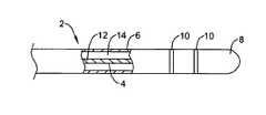
- FIG. 1depicts a diagrammatic cross-sectional view of a guidewire
- FIG. 2depicts a diagrammatic cross-sectional view of a guidewire
- FIG. 3depicts a lateral cross-section of the guidewire of FIG. 2 ;
- FIG. 4depicts a partial plan view of a guide catheter
- FIG. 5depicts a lateral cross-section of the guide catheter of FIG. 4 ;
- FIG. 6depicts a partial plan view of a guide catheter
- FIG. 7depicts a partial plan view of a balloon catheter
- FIG. 8depicts a perspective view of a stent.
- Torqueabilityis the ability to transmit a rotational force from a proximal portion to a distal portion. Torqueability may be advantageous if a guidewire is shaped to conform to specific vasculature, and the guidewire needs to be specifically oriented to take full advantage of its shape.
- Pushabilityis the ability to transmit a longitudinal force from a proximal portion to a distal portion so that the longitudinal displacement of the distal portion is approximately the same as the longitudinal displacement of the proximal portion. In contrast, a device that does not exhibit a high degree of pushability would displace laterally near the proximal portion, creating bends or curves in the device. Flexibility is the ability of a device to bend without breaking or elastic deformation.
- FIG. 1is a diagrammatic cross-sectional view of a guidewire 2 .
- Guidewire 2includes a core member 4 and an outer lubricious sheath 6 .
- Guidewire 2may also include an atraumatic distal tip 8 and one or more radiopaque markers 10 or may include a radiopaque material incorporated into one or more of the materials.
- a radiopaque materialmay be incorporated into core member 4 or distal tip 8 .
- Core member 4is preferably made from a thermoplastic rigid rod polymer. Consequently, guidewire 2 may be compatible with magnetic resonance imaging while retaining necessary torqueability, pushability and flexibility requirements.
- Core member 4may have a variable cross section. For instance, it may be distally tapered, it may have tapering regions and straight regions, or it may have one or more necked region.
- Core member 4may include another polymer such as polyimide, for example, in additional to the thermoplastic rigid rod polymer.
- Guidewire 2may be formed by extruding core member 4 and extruding sheath 6 over core member 4 .
- Sheath 6may be lubricious and may include therapeutic agents.
- sheath 6may include PTFE or may include a drug infused hydrogel.
- core member 4may be formed by coextruding the thermoplastic rigid rod polymer with another compatible polymer. The coextrusion process may be controlled to extrude variable amounts of the thermoplastic rigid rod polymer and the other polymer to produce a variable stiffness core member.
- core member 4may be formed from coextruding a first blend 12 and a second blend 14 , each blend including a thermoplastic rigid rod polymer.
- FIG. 2is a diagrammatic cross sectional view of an example guidewire 102 .
- Guidewire 102includes a core 104 formed from a plurality of elongate fibers 112 , several of the fibers 112 including a thermoplastic rigid rod polymer, and may include a lubricious or polymeric sheath 106 .
- all fibers 112may include the thermoplastic rigid rod polymer.
- some fibers 112may include the thermoplastic rigid rod polymer and other fibers 112 may include other polymers or materials.
- Some fibers 112may vary from a first material to a second material along the length of the fiber. Fibers 112 are selected to provide for desired characteristics along the length of guidewire 102 .
- the number and composition of fibers 112affect the performance of guidewire 102 . Generally the more fibers that include a thermoplastic rigid rod polymer, and the more of that material that is in each fiber, the fewer fibers are needed to achieve a desired level of torqueability and pushability. Other variations are contemplated as well.
- Fibers 112may be of variable length to permit the guidewire to taper distally. Thus, all fibers 112 would be present at a proximal portion and fewer fibers would be present distally.
- each fibermay have a tapering cross section. Variations in the cross-sectional shape are contemplated. For instance, the cross-sectional shape of certain fibers may be circular, pentagonal or square.
- FIG. 3is a cross-sectional view through the section lines 3 - 3 of FIG. 2 .
- Guidewire 102includes a core 104 formed from a plurality of fibers 112 encased by a sheath 106 .
- FIG. 4is a partial plan view of an example guide catheter 302 with selected portions removed.
- FIG. 5is a transverse cross-sectional view of the catheter of FIG. 4 .
- Guide catheter 302has a layer 304 including a thermoplastic rigid rod polymer and may include additional layers 306 and 308 .
- Layer 304may be a smooth tubular sheath or may be a weave, mesh, or coil.
- Layer 304may include other polymers. For example, if layer 304 is a weave, strands made from other polymers may be woven in or the thermoplastic rigid rod weave may be imbedded in a layer having another polymer. Alternatively, the thermoplastic rigid rod polymer may be blended with other polymers.
- Guide catheter 302may have a rigid rod thermoplastic layer directly bonded to a lubricious layer such as a high density polyethylene. Of course, the rigid rod thermoplastic layer may be a blended layer including one or more other polymers.
- FIG. 6is a partial plan view of an example guide catheter 402 with selected portions removed.
- Guide catheter 402has a tubular layer 404 having elongate thermoplastic rigid rod fibers 410 retained between a first tubular layer 406 and a second tubular layer 408 .
- Fibers 410have proximal ends 420 and distal ends 422 which may be embedded in a proximal retaining ring and a distal retaining ring.
- fibers 410may be embedded in a retaining material 424 such as a polymer adhesive such as epoxy or polyurethane. Selected segments of fibers 410 may be embedded in a retaining material and other segments of fibers 410 may be free. This may be varied along the length of the catheter to provide desired flexibilities and shapes of the catheter.
- Fibers 410may have a circular cross sectional shape, rectangular cross-section shape, or other suitable shape.
- FIG. 7is a partial plan view of an example balloon catheter 502 .
- Balloon catheter 502includes a catheter shaft 504 defining an inflation lumen fluidly connected to balloon 508 and may include a guidewire lumen.
- Balloon 508includes a balloon wall 510 made from a rigid rod thermoplastic polymer, which may also be blended or coextruded with other polymers.
- Balloon wallmay have a thickness of between 0.25 and 5.0 mils or between 0.3 and 1.0 mils while retaining sufficient burst strength to do a typical angioplasty or stent procedure.
- Balloon wall 510may include a rigid rod thermoplastic polymer mesh or weave embedded in another polymer such as Nylon. The other polymer may be non-cross linked or it may be cross-linked, depending on the desired properties.
- FIG. 8is a perspective view of an example stent 600 .
- Stent 600includes one or more struts 602 made from a rigid rod thermoplastic polymer arranged in a lattice-work configuration. Other suitable arrangements are contemplated.
- Stent 600may include a coating which provides enhanced lubricity, carries a therapeutic agent, or provides other desired functionality.
- Stent 600may also include radiopaque or paramagnetic materials to provide enhanced visibility.
- Stent 600may be primarily polymeric, being made substantially from the rigid rod thermoplastic polymer, and consequently may be MRI compatible.
- Stent 600may be made through compression molding or through laser cutting a tubular extrusion into the desired configuration, or through other suitable method.
- any of the medical devices described hereinmay be provided with a coating on a surface of the device.
- Such coatingsmay be provided for various purposes including, but not limited to, carrying a therapeutic agent for localized delivery to a target area within the body; providing a lubricious surface to facilitate introduction of the medical device into the patient during an interventional procedure; improving the biocompatibility of the medical device with the surrounding environment; or, for a combination of such or other purposes.
- coatingsthat have been proposed for implantable or insertable medical devices are polymeric materials such as hydrogels.
- Hydrogelsare typically hydrophilic polymeric materials that have the ability to absorb large amounts, up to many times the weight of the hydrogel itself, of water or other polar molecules. Hydrogels have been disclosed as coatings for implantable or insertable medical devices or as materials for constructing the device itself in, for example, U.S. Pat. Nos. 6,316,522; 6,261,630; 6,184,266; 6,176,849; 6,096,108; 6,060,534; 5,702,754; 5,693,034; and, 5,304,121, each of which is assigned to Boston Scientific Corporation or SciMed Life Systems, Inc. and is incorporated herein in its entirety by reference. Hydrogels, such as those described in the foregoing exemplary U.S.
- hydrogelscan be based on synthetic or naturally occurring materials, or a composite thereof; can be biodegradable or substantially non-biodegradable; and, can be modified or derivatized in numerous ways to render the hydrogel more suitable for a desired purpose.
- the hydrogelcan be modified by chemically cross-linking with, for example, a polyfunctional cross-linking agent that is reactive with functional groups covalently bonded to the polymer structure.
- the hydrogel polymercan also be ionically cross-linked with, for example, polyvalent metal ions.
- Many hydrogel polymers mentioned hereincan be both chemically and ionically cross-linked. Therefore, chemically and ionically cross-linkable hydrogel polymers are not necessarily mutually exclusive groups of hydrogel polymers.
- Cross-linking of a hydrogel polymercan be advantageous, for example, to provide a more rigid material. Cross-linking may also be conducted, for example, to render the hydrogel less soluble in a particular environment or to modify the ability of the hydrogel polymer to absorb water or to modify the manner in which water or other molecules, compounds or groups are associated with the hydrogel polymer
- hydrogel polymersthat can be adapted to render a medical device lubricious surface, without limitation, polyacrylates; poly(acrylic acid); poly(methacrylic acid); polyacrylamides; poly(N-alkylacrylamides); polyalkylene oxides; poly(ethylene oxide); poly(propylene) oxide; poly(vinyl alcohol); polyvinyl aromatics; poly(vinylpyrrolidone); poly(ethyleneimine); polyethylene amine; polyacrylonitrile; polyvinyl sulfonic acid; polyamides; poly(L-lysine); hydrophilic polyurethanes; maleic anhydride polymers; proteins; collagen;
- Paramagnetic materialssuch as paramagnetic ions and paramagnetic particles may be incorporated into a medical device such as those described above.
- the paramagnetic materialsmay be incorporated into one or more of the polymers of the medical device.
- Paramagnetic materialsare typically those that have a strong magnetic moment relative to detectable protons in water or other molecules, compounds or groups in the vicinity of the paramagnetic materials.
- Elements with atomic numbers 21-29, 42, 44, and 58-70such as chromium (III), manganese (II), iron (III), iron (II), cobalt (II), copper (II), nickel (II), praesodymium (III), neodymium (III), samarium (III), ytterbium (III), gadolinium (III), terbium (III), dysprosium (III), holmium (III) and erbium (III) are examples of paramagnetic elements that may be suitable. The addition of paramagnetic materials may enhance MRI visualization of the medical device, for example.
- thermoplastic rigid rod polymeris a meltable polymer having constitutional or configurational units that form a generally linear chain that is rigid.
- Thermoplastic rigid rod polymerstherefore may have increased strength compared with other thermoplastics.
- Thermoplastic rigid rod polymersmay also have improved processing characteristics and good compatibility with other polymers compared with other polymers of similar strength.
- Thermoplastic rigid rod polymersmay be cross-linked by cooling down from an extrusion process. Most other polymers require a radiation or chemical process to cross-link.
- a medical device made from a thermoplastic rigid rod polymer in combination with another polymermay have a cross-linked portion, which may increase strength, and a non-cross-linked portion, which may increase softness, flexibility or other suitable attribute.
- thermoplastic rigid rod polymermay provide a combination of physical properties not available with a different polymer.
- the thermoplastic rigid rod polymermay be substituted poly(1,4-phenylene).
- the substituted poly(1,4-phenylene)includes a plurality of benzoyl substituted 1,4-phenylene units.
Landscapes
- Health & Medical Sciences (AREA)
- Epidemiology (AREA)
- Life Sciences & Earth Sciences (AREA)
- Animal Behavior & Ethology (AREA)
- General Health & Medical Sciences (AREA)
- Public Health (AREA)
- Veterinary Medicine (AREA)
- Physics & Mathematics (AREA)
- Optics & Photonics (AREA)
- Heart & Thoracic Surgery (AREA)
- Surgery (AREA)
- Vascular Medicine (AREA)
- Materials For Medical Uses (AREA)
- Media Introduction/Drainage Providing Device (AREA)
- Polyoxymethylene Polymers And Polymers With Carbon-To-Carbon Bonds (AREA)
- Polyesters Or Polycarbonates (AREA)
Abstract
Description
Claims (48)
Priority Applications (6)
| Application Number | Priority Date | Filing Date | Title |
|---|---|---|---|
| US10/811,277US8067073B2 (en) | 2004-03-25 | 2004-03-25 | Thermoplastic medical device |
| AT05724910TATE482729T1 (en) | 2004-03-25 | 2005-03-08 | MEDICAL DEVICE WITH THERMOPLASTIC SUBSTITUTED POLY(1,4-PHENYLENE) RIGID-ROD POLYMER |
| EP05724910AEP1740234B8 (en) | 2004-03-25 | 2005-03-08 | Medical device comprising thermoplastic substituted poly(1,4-phenylene) rigid-rod polymer |
| PCT/US2005/007472WO2005102406A1 (en) | 2004-03-25 | 2005-03-08 | Medical device comprising thermoplastic rigid-rod polymer |
| DE602005023849TDE602005023849D1 (en) | 2004-03-25 | 2005-03-08 | Medizinprodukt mit thermoplastischem substituiertem poly(1,4-phenylene) rigid-rod polymer |
| US13/274,487US20120035591A1 (en) | 2004-03-25 | 2011-10-17 | Thermoplastic medical device |
Applications Claiming Priority (1)
| Application Number | Priority Date | Filing Date | Title |
|---|---|---|---|
| US10/811,277US8067073B2 (en) | 2004-03-25 | 2004-03-25 | Thermoplastic medical device |
Related Child Applications (1)
| Application Number | Title | Priority Date | Filing Date |
|---|---|---|---|
| US13/274,487ContinuationUS20120035591A1 (en) | 2004-03-25 | 2011-10-17 | Thermoplastic medical device |
Publications (2)
| Publication Number | Publication Date |
|---|---|
| US20050214492A1 US20050214492A1 (en) | 2005-09-29 |
| US8067073B2true US8067073B2 (en) | 2011-11-29 |
Family
ID=34962809
Family Applications (2)
| Application Number | Title | Priority Date | Filing Date |
|---|---|---|---|
| US10/811,277Expired - Fee RelatedUS8067073B2 (en) | 2004-03-25 | 2004-03-25 | Thermoplastic medical device |
| US13/274,487AbandonedUS20120035591A1 (en) | 2004-03-25 | 2011-10-17 | Thermoplastic medical device |
Family Applications After (1)
| Application Number | Title | Priority Date | Filing Date |
|---|---|---|---|
| US13/274,487AbandonedUS20120035591A1 (en) | 2004-03-25 | 2011-10-17 | Thermoplastic medical device |
Country Status (5)
| Country | Link |
|---|---|
| US (2) | US8067073B2 (en) |
| EP (1) | EP1740234B8 (en) |
| AT (1) | ATE482729T1 (en) |
| DE (1) | DE602005023849D1 (en) |
| WO (1) | WO2005102406A1 (en) |
Cited By (2)
| Publication number | Priority date | Publication date | Assignee | Title |
|---|---|---|---|---|
| US10953204B2 (en) | 2017-01-09 | 2021-03-23 | Boston Scientific Scimed, Inc. | Guidewire with tactile feel |
| US11202888B2 (en) | 2017-12-03 | 2021-12-21 | Cook Medical Technologies Llc | MRI compatible interventional wireguide |
Families Citing this family (14)
| Publication number | Priority date | Publication date | Assignee | Title |
|---|---|---|---|---|
| US20060058582A1 (en)* | 2002-06-13 | 2006-03-16 | Usgi Medical Inc. | Disposable shapelocking system |
| US20080319389A1 (en)* | 2004-09-28 | 2008-12-25 | Davis-Lemessy Patricia A | Medical Devices with Rigid Rod Paraphenylene |
| US20070270971A1 (en)* | 2006-03-14 | 2007-11-22 | Sdgi Holdings, Inc. | Intervertebral prosthetic disc with improved wear resistance |
| US20070270970A1 (en)* | 2006-03-14 | 2007-11-22 | Sdgi Holdings, Inc. | Spinal implants with improved wear resistance |
| US20070233246A1 (en)* | 2006-03-31 | 2007-10-04 | Sdgi Holdings, Inc. | Spinal implants with improved mechanical response |
| EP2200672B1 (en)* | 2007-09-11 | 2012-06-27 | Solvay Specialty Polymers USA, LLC. | Improved prosthetic devices |
| US8119764B2 (en)* | 2007-09-11 | 2012-02-21 | Solvay Advanced Polymers, L.L.C. | Medical devices made of a polymer material |
| US8742064B2 (en)* | 2007-10-23 | 2014-06-03 | Solvay Advanced Polymers, L.L.C. | Medical tubings made of a polymer material |
| US8684999B2 (en)* | 2007-12-31 | 2014-04-01 | St. Jude Medical, Atrial Fibrillation Division, Inc. | Catheter shaft and method of manufacture |
| DE102008024976A1 (en)* | 2008-05-23 | 2009-12-17 | Marvis Technologies Gmbh | Medical instrument |
| EP3508244A1 (en)* | 2010-02-09 | 2019-07-10 | Medinol Ltd. | System for traversing vessel occlusions |
| JP2014100339A (en)* | 2012-11-20 | 2014-06-05 | Terumo Corp | Catheter tube manufacturing method and continuous body of catheter tubes |
| US20150306355A1 (en)* | 2014-04-28 | 2015-10-29 | Mark Edman Idstrom | Guidewires with variable rigidity |
| US10493107B2 (en) | 2014-06-09 | 2019-12-03 | Cornell University | Implantable therapeutic delivery system and methods thereof |
Citations (20)
| Publication number | Priority date | Publication date | Assignee | Title |
|---|---|---|---|---|
| US3388095A (en)* | 1965-06-15 | 1968-06-11 | Polychemie Aku Ge Nv | Stabilized poly (2, 6-dimethyl-1, 4-phenylene) ether |
| US5227457A (en) | 1988-02-17 | 1993-07-13 | Maxdem Incorporated | Rigid-rod polymers |
| US5247057A (en) | 1992-03-23 | 1993-09-21 | The United States Of America As Represented By The Secretary Of The Air Force | Insitu molecular composites based on rigid-rod polyimides |
| US5248305A (en) | 1989-08-04 | 1993-09-28 | Cordis Corporation | Extruded tubing and catheters having helical liquid crystal fibrils |
| US5514379A (en)* | 1992-08-07 | 1996-05-07 | The General Hospital Corporation | Hydrogel compositions and methods of use |
| US5731400A (en) | 1988-02-17 | 1998-03-24 | Maxdem Incorporated | Rigid-rod polymers |
| US5760131A (en) | 1988-02-17 | 1998-06-02 | Maxdem Incorporated | Rigid-rod polymers |
| US6025439A (en) | 1998-07-30 | 2000-02-15 | The United States Of America As Represented By The Secretary Of The Air Force | Processing of thermoplastic rigid-rod molecular composites |
| US6024722A (en)* | 1994-01-06 | 2000-02-15 | Scimed Life Systems, Inc. | Thermoplastic polyimide balloon catheter construction |
| US6228285B1 (en) | 1997-06-04 | 2001-05-08 | The University Of Dayton | Method for processing rigid-chain polymers into structural materials |
| US6242063B1 (en) | 1997-09-10 | 2001-06-05 | Scimed Life Systems, Inc. | Balloons made from liquid crystal polymer blends |
| US6284333B1 (en) | 1997-09-10 | 2001-09-04 | Scimed Life Systems, Inc. | Medical devices made from polymer blends containing low melting temperature liquid crystal polymers |
| US6436056B1 (en) | 1996-02-28 | 2002-08-20 | Boston Scientific Corporation | Polymeric implements for torque transmission |
| US6517570B1 (en)* | 1994-08-31 | 2003-02-11 | Gore Enterprise Holdings, Inc. | Exterior supported self-expanding stent-graft |
| EP1352731A2 (en) | 1992-03-06 | 2003-10-15 | Mississippi Polymer Technologies, Inc. | Method of orienting polymer molecules |
| US6676971B2 (en) | 2000-03-13 | 2004-01-13 | Biocure, Inc. | Embolic compositions |
| WO2004004592A1 (en) | 2002-07-03 | 2004-01-15 | University Of Connecticut | Advanced thermoplastics for orthodontics |
| US6730377B2 (en) | 2002-01-23 | 2004-05-04 | Scimed Life Systems, Inc. | Balloons made from liquid crystal polymer blends |
| WO2004106420A2 (en) | 2003-05-22 | 2004-12-09 | Zyvex Corporation | Nanocomposites and method for production |
| EP1522549A1 (en) | 2003-09-26 | 2005-04-13 | Hexcel Corporation | Heat-settable resins |
Family Cites Families (33)
| Publication number | Priority date | Publication date | Assignee | Title |
|---|---|---|---|---|
| CA1153264A (en)* | 1979-02-08 | 1983-09-06 | Hidenaga Yoshimura | Medical vascular guide wire and self-guiding type catheter |
| US4867174A (en)* | 1987-11-18 | 1989-09-19 | Baxter Travenol Laboratories, Inc. | Guidewire for medical use |
| US4884579A (en)* | 1988-04-18 | 1989-12-05 | Target Therapeutics | Catheter guide wire |
| US5304121A (en) | 1990-12-28 | 1994-04-19 | Boston Scientific Corporation | Drug delivery system making use of a hydrogel polymer coating |
| JPH04130131A (en)* | 1990-09-20 | 1992-05-01 | Polyplastics Co | Easily processable, wholly aromatic polyester |
| WO1993011751A1 (en) | 1991-12-18 | 1993-06-24 | Scimed Life Systems, Inc. | Lubricous polymer network |
| US5981007A (en)* | 1992-03-31 | 1999-11-09 | Foster-Miller, Inc. | Extruded thermoplastic, liquid crystalline polymers and blends thereof having a planar morphology |
| US5667499A (en)* | 1994-10-04 | 1997-09-16 | Scimed Life Systems, Inc. | Guide catheter unibody |
| US5702754A (en) | 1995-02-22 | 1997-12-30 | Meadox Medicals, Inc. | Method of providing a substrate with a hydrophilic coating and substrates, particularly medical devices, provided with such coatings |
| US5680873A (en)* | 1995-03-02 | 1997-10-28 | Scimed Life Systems, Inc. | Braidless guide catheter |
| US5833632A (en)* | 1995-12-07 | 1998-11-10 | Sarcos, Inc. | Hollow guide wire apparatus catheters |
| US5836893A (en)* | 1996-03-08 | 1998-11-17 | Scimed Life Systems, Inc. | Intravascular guidewire |
| US6060534A (en) | 1996-07-11 | 2000-05-09 | Scimed Life Systems, Inc. | Medical devices comprising ionically and non-ionically crosslinked polymer hydrogels having improved mechanical properties |
| EP0934092A4 (en)* | 1997-03-06 | 2008-03-26 | Boston Scient Scimed Inc | DEVICE AND METHOD FOR DISTAL PROTECTION |
| US6221467B1 (en) | 1997-06-03 | 2001-04-24 | Scimed Life Systems, Inc. | Coating gradient for lubricious coatings on balloon catheters |
| US6316522B1 (en) | 1997-08-18 | 2001-11-13 | Scimed Life Systems, Inc. | Bioresorbable hydrogel compositions for implantable prostheses |
| US6096108A (en) | 1997-10-22 | 2000-08-01 | Donaldson Company, Inc. | Air cleaner mounting arrangement and method |
| US6306105B1 (en)* | 1998-05-14 | 2001-10-23 | Scimed Life Systems, Inc. | High performance coil wire |
| US6176849B1 (en) | 1999-05-21 | 2001-01-23 | Scimed Life Systems, Inc. | Hydrophilic lubricity coating for medical devices comprising a hydrophobic top coat |
| JP4059656B2 (en)* | 2001-03-07 | 2008-03-12 | オリンパス株式会社 | Biological tissue clip device |
| CA2452977C (en)* | 2001-03-08 | 2013-07-16 | The Trustees Of The University Of Pennsylvania | Facially amphiphilic polymers as anti-infective agents |
| US7025734B1 (en)* | 2001-09-28 | 2006-04-11 | Advanced Cardiovascular Systmes, Inc. | Guidewire with chemical sensing capabilities |
| US6612998B2 (en)* | 2001-11-28 | 2003-09-02 | Advanced Cardiovascular Systems, Inc. | Guide wire with marker sleeve |
| US6832715B2 (en)* | 2001-12-03 | 2004-12-21 | Scimed Life Systems, Inc. | Guidewire distal tip soldering method |
| US7118539B2 (en)* | 2002-02-26 | 2006-10-10 | Scimed Life Systems, Inc. | Articulating guide wire for embolic protection and methods of use |
| US7309318B2 (en)* | 2002-09-18 | 2007-12-18 | Boston Scientific Scimed, Inc. | Flexible composite guidewire for intravascular catheter |
| US7951091B2 (en)* | 2003-07-31 | 2011-05-31 | Tyco Healthcare Group Lp | Guide wire with stranded tip |
| US20080319389A1 (en)* | 2004-09-28 | 2008-12-25 | Davis-Lemessy Patricia A | Medical Devices with Rigid Rod Paraphenylene |
| US8070718B2 (en)* | 2004-12-13 | 2011-12-06 | Boston Scientific Scimed, Inc. | Medical devices formed with a sacrificial structure and processes of forming the same |
| DE102005022688B4 (en)* | 2005-05-12 | 2011-06-30 | EPflex Feinwerktechnik GmbH, 72581 | Guidewire for a medical instrument |
| US8961532B2 (en)* | 2006-01-06 | 2015-02-24 | Bayer Essure Inc. | Atraumatic catheter tip |
| US8119764B2 (en)* | 2007-09-11 | 2012-02-21 | Solvay Advanced Polymers, L.L.C. | Medical devices made of a polymer material |
| US8742064B2 (en)* | 2007-10-23 | 2014-06-03 | Solvay Advanced Polymers, L.L.C. | Medical tubings made of a polymer material |
- 2004
- 2004-03-25USUS10/811,277patent/US8067073B2/ennot_activeExpired - Fee Related
- 2005
- 2005-03-08ATAT05724910Tpatent/ATE482729T1/ennot_activeIP Right Cessation
- 2005-03-08EPEP05724910Apatent/EP1740234B8/ennot_activeNot-in-force
- 2005-03-08WOPCT/US2005/007472patent/WO2005102406A1/enactiveApplication Filing
- 2005-03-08DEDE602005023849Tpatent/DE602005023849D1/ennot_activeExpired - Lifetime
- 2011
- 2011-10-17USUS13/274,487patent/US20120035591A1/ennot_activeAbandoned
Patent Citations (22)
| Publication number | Priority date | Publication date | Assignee | Title |
|---|---|---|---|---|
| US3388095A (en)* | 1965-06-15 | 1968-06-11 | Polychemie Aku Ge Nv | Stabilized poly (2, 6-dimethyl-1, 4-phenylene) ether |
| US6087467A (en) | 1988-02-17 | 2000-07-11 | Maxdem Incorporated | Rigid-rod polymers |
| US5731400A (en) | 1988-02-17 | 1998-03-24 | Maxdem Incorporated | Rigid-rod polymers |
| US5760131A (en) | 1988-02-17 | 1998-06-02 | Maxdem Incorporated | Rigid-rod polymers |
| US5976437A (en) | 1988-02-17 | 1999-11-02 | Maxdem Incorporated | Rigid-rod polymers |
| US5227457A (en) | 1988-02-17 | 1993-07-13 | Maxdem Incorporated | Rigid-rod polymers |
| US5248305A (en) | 1989-08-04 | 1993-09-28 | Cordis Corporation | Extruded tubing and catheters having helical liquid crystal fibrils |
| EP1352731A2 (en) | 1992-03-06 | 2003-10-15 | Mississippi Polymer Technologies, Inc. | Method of orienting polymer molecules |
| US5247057A (en) | 1992-03-23 | 1993-09-21 | The United States Of America As Represented By The Secretary Of The Air Force | Insitu molecular composites based on rigid-rod polyimides |
| US5514379A (en)* | 1992-08-07 | 1996-05-07 | The General Hospital Corporation | Hydrogel compositions and methods of use |
| US6024722A (en)* | 1994-01-06 | 2000-02-15 | Scimed Life Systems, Inc. | Thermoplastic polyimide balloon catheter construction |
| US6517570B1 (en)* | 1994-08-31 | 2003-02-11 | Gore Enterprise Holdings, Inc. | Exterior supported self-expanding stent-graft |
| US6436056B1 (en) | 1996-02-28 | 2002-08-20 | Boston Scientific Corporation | Polymeric implements for torque transmission |
| US6228285B1 (en) | 1997-06-04 | 2001-05-08 | The University Of Dayton | Method for processing rigid-chain polymers into structural materials |
| US6242063B1 (en) | 1997-09-10 | 2001-06-05 | Scimed Life Systems, Inc. | Balloons made from liquid crystal polymer blends |
| US6284333B1 (en) | 1997-09-10 | 2001-09-04 | Scimed Life Systems, Inc. | Medical devices made from polymer blends containing low melting temperature liquid crystal polymers |
| US6025439A (en) | 1998-07-30 | 2000-02-15 | The United States Of America As Represented By The Secretary Of The Air Force | Processing of thermoplastic rigid-rod molecular composites |
| US6676971B2 (en) | 2000-03-13 | 2004-01-13 | Biocure, Inc. | Embolic compositions |
| US6730377B2 (en) | 2002-01-23 | 2004-05-04 | Scimed Life Systems, Inc. | Balloons made from liquid crystal polymer blends |
| WO2004004592A1 (en) | 2002-07-03 | 2004-01-15 | University Of Connecticut | Advanced thermoplastics for orthodontics |
| WO2004106420A2 (en) | 2003-05-22 | 2004-12-09 | Zyvex Corporation | Nanocomposites and method for production |
| EP1522549A1 (en) | 2003-09-26 | 2005-04-13 | Hexcel Corporation | Heat-settable resins |
Non-Patent Citations (1)
| Title |
|---|
| Mississippi Polymer Technologies, "Parmax® Applications", http://www.mptpolymers.com/applications.shtml, Sep. 4, 2003, 5 pgs. |
Cited By (4)
| Publication number | Priority date | Publication date | Assignee | Title |
|---|---|---|---|---|
| US10953204B2 (en) | 2017-01-09 | 2021-03-23 | Boston Scientific Scimed, Inc. | Guidewire with tactile feel |
| US11202888B2 (en) | 2017-12-03 | 2021-12-21 | Cook Medical Technologies Llc | MRI compatible interventional wireguide |
| US11724073B2 (en) | 2017-12-03 | 2023-08-15 | Cook Medical Technologies Llc | MRI compatible interventional wireguide |
| US12128197B2 (en) | 2017-12-03 | 2024-10-29 | Cook Medical Technologies Llc | MRI compatible interventional wireguide |
Also Published As
| Publication number | Publication date |
|---|---|
| US20050214492A1 (en) | 2005-09-29 |
| ATE482729T1 (en) | 2010-10-15 |
| DE602005023849D1 (en) | 2010-11-11 |
| US20120035591A1 (en) | 2012-02-09 |
| WO2005102406A1 (en) | 2005-11-03 |
| EP1740234B1 (en) | 2010-09-29 |
| EP1740234B8 (en) | 2010-12-15 |
| EP1740234A1 (en) | 2007-01-10 |
Similar Documents
| Publication | Publication Date | Title |
|---|---|---|
| US20120035591A1 (en) | Thermoplastic medical device | |
| US8377035B2 (en) | Unbalanced reinforcement members for medical device | |
| CA2519166C (en) | Medical devices | |
| US5951539A (en) | Optimized high performance multiple coil spiral-wound vascular catheter | |
| DE69727238T2 (en) | GUIDE CATHETER WITH IMPROVED GUIDE WIRE TRACKING | |
| US6689120B1 (en) | Reduced profile delivery system | |
| CA2457146C (en) | Microcatheter with improved distal tip and transitions | |
| EP1551489B1 (en) | Wire braid-reinforced microcatheter | |
| US6053903A (en) | High performance spiral-wound catheter | |
| EP1379311B1 (en) | Microcatheter with improved distal tip and transitions | |
| AU684980B2 (en) | Kink-free spiral-wound catheter | |
| US6152912A (en) | Optimized high performance spiral-wound vascular catheter | |
| US5891112A (en) | High performance superelastic alloy braid reinforced catheter | |
| WO2005030310A1 (en) | Surface modified reinforcing member for medical device and method for making same | |
| JPH08508928A (en) | Catheter with kink-resistant distal tip | |
| EP1207930B1 (en) | Reduced profile delivery system | |
| WO2008056625A1 (en) | Catheter tube for medical use | |
| EP3485931A1 (en) | Ureteral catheter |
Legal Events
| Date | Code | Title | Description |
|---|---|---|---|
| AS | Assignment | Owner name:SCIMED LIFE SYSTEMS, INC., MINNESOTA Free format text:ASSIGNMENT OF ASSIGNORS INTEREST;ASSIGNORS:ZHONG, SHENG-PING;CHIN, YEM;SCOPTON, PAUL M.;REEL/FRAME:015161/0489;SIGNING DATES FROM 20040227 TO 20040319 Owner name:SCIMED LIFE SYSTEMS, INC., MINNESOTA Free format text:ASSIGNMENT OF ASSIGNORS INTEREST;ASSIGNORS:ZHONG, SHENG-PING;CHIN, YEM;SCOPTON, PAUL M.;SIGNING DATES FROM 20040227 TO 20040319;REEL/FRAME:015161/0489 | |
| FEPP | Fee payment procedure | Free format text:PAYER NUMBER DE-ASSIGNED (ORIGINAL EVENT CODE: RMPN); ENTITY STATUS OF PATENT OWNER: LARGE ENTITY Free format text:PAYOR NUMBER ASSIGNED (ORIGINAL EVENT CODE: ASPN); ENTITY STATUS OF PATENT OWNER: LARGE ENTITY | |
| ZAAA | Notice of allowance and fees due | Free format text:ORIGINAL CODE: NOA | |
| ZAAB | Notice of allowance mailed | Free format text:ORIGINAL CODE: MN/=. | |
| AS | Assignment | Owner name:BOSTON SCIENTIFIC SCIMED, INC., MINNESOTA Free format text:MERGER;ASSIGNOR:SCIMED LIFE SYSTEMS, INC.;REEL/FRAME:026932/0198 Effective date:20041222 | |
| STCF | Information on status: patent grant | Free format text:PATENTED CASE | |
| FPAY | Fee payment | Year of fee payment:4 | |
| MAFP | Maintenance fee payment | Free format text:PAYMENT OF MAINTENANCE FEE, 8TH YEAR, LARGE ENTITY (ORIGINAL EVENT CODE: M1552); ENTITY STATUS OF PATENT OWNER: LARGE ENTITY Year of fee payment:8 | |
| FEPP | Fee payment procedure | Free format text:MAINTENANCE FEE REMINDER MAILED (ORIGINAL EVENT CODE: REM.); ENTITY STATUS OF PATENT OWNER: LARGE ENTITY | |
| LAPS | Lapse for failure to pay maintenance fees | Free format text:PATENT EXPIRED FOR FAILURE TO PAY MAINTENANCE FEES (ORIGINAL EVENT CODE: EXP.); ENTITY STATUS OF PATENT OWNER: LARGE ENTITY | |
| STCH | Information on status: patent discontinuation | Free format text:PATENT EXPIRED DUE TO NONPAYMENT OF MAINTENANCE FEES UNDER 37 CFR 1.362 | |
| FP | Lapsed due to failure to pay maintenance fee | Effective date:20231129 |