US8066760B2 - Stent with movable crown - Google Patents
Stent with movable crownDownload PDFInfo
- Publication number
- US8066760B2 US8066760B2US11/379,161US37916106AUS8066760B2US 8066760 B2US8066760 B2US 8066760B2US 37916106 AUS37916106 AUS 37916106AUS 8066760 B2US8066760 B2US 8066760B2
- Authority
- US
- United States
- Prior art keywords
- stent
- portions
- crown
- strut
- configuration
- Prior art date
- Legal status (The legal status is an assumption and is not a legal conclusion. Google has not performed a legal analysis and makes no representation as to the accuracy of the status listed.)
- Expired - Fee Related, expires
Links
- 230000002265preventionEffects0.000claimsabstractdescription17
- 238000000034methodMethods0.000claimsabstractdescription11
- 239000000463materialSubstances0.000claimsdescription20
- 229920000642polymerPolymers0.000claimsdescription16
- 230000002792vascularEffects0.000claimsdescription11
- -1polyethylenePolymers0.000claimsdescription10
- 238000005482strain hardeningMethods0.000claimsdescription6
- 239000004952PolyamideSubstances0.000claimsdescription4
- 229920002647polyamidePolymers0.000claimsdescription4
- 229920002635polyurethanePolymers0.000claimsdescription4
- 239000004814polyurethaneSubstances0.000claimsdescription4
- 239000004698PolyethyleneSubstances0.000claimsdescription3
- 239000004743PolypropyleneSubstances0.000claimsdescription3
- 229920000573polyethylenePolymers0.000claimsdescription3
- 229920001155polypropylenePolymers0.000claimsdescription3
- 229920001343polytetrafluoroethylenePolymers0.000claimsdescription3
- 239000004810polytetrafluoroethyleneSubstances0.000claimsdescription3
- 229920000954PolyglycolidePolymers0.000claimsdescription2
- 239000004372Polyvinyl alcoholSubstances0.000claimsdescription2
- 229920002988biodegradable polymerPolymers0.000claimsdescription2
- 239000004621biodegradable polymerSubstances0.000claimsdescription2
- 230000008859changeEffects0.000claimsdescription2
- 229920001577copolymerPolymers0.000claimsdescription2
- 229920000747poly(lactic acid)Polymers0.000claimsdescription2
- 229920003229poly(methyl methacrylate)Polymers0.000claimsdescription2
- 229920000728polyesterPolymers0.000claimsdescription2
- 239000004633polyglycolic acidSubstances0.000claimsdescription2
- 239000004626polylactic acidSubstances0.000claimsdescription2
- 239000004926polymethyl methacrylateSubstances0.000claimsdescription2
- 229920002451polyvinyl alcoholPolymers0.000claimsdescription2
- 210000000748cardiovascular systemAnatomy0.000abstractdescription3
- 230000005856abnormalityEffects0.000abstractdescription2
- 206010061218InflammationDiseases0.000description4
- 230000004054inflammatory processEffects0.000description4
- 230000004044responseEffects0.000description4
- 208000007536ThrombosisDiseases0.000description3
- 239000003814drugSubstances0.000description3
- 239000007943implantSubstances0.000description3
- 230000003902lesionEffects0.000description3
- 239000002184metalSubstances0.000description3
- 229910052751metalInorganic materials0.000description3
- 150000002739metalsChemical class0.000description3
- 208000005422Foreign-Body reactionDiseases0.000description2
- PXHVJJICTQNCMI-UHFFFAOYSA-NNickelChemical compound[Ni]PXHVJJICTQNCMI-UHFFFAOYSA-N0.000description2
- 230000017531blood circulationEffects0.000description2
- 230000004663cell proliferationEffects0.000description2
- 238000000576coating methodMethods0.000description2
- 229940079593drugDrugs0.000description2
- FUZZWVXGSFPDMH-UHFFFAOYSA-Nhexanoic acidChemical compoundCCCCCC(O)=OFUZZWVXGSFPDMH-UHFFFAOYSA-N0.000description2
- 238000003780insertionMethods0.000description2
- 230000037431insertionEffects0.000description2
- BASFCYQUMIYNBI-UHFFFAOYSA-NplatinumChemical compound[Pt]BASFCYQUMIYNBI-UHFFFAOYSA-N0.000description2
- 239000010935stainless steelSubstances0.000description2
- 229910001220stainless steelInorganic materials0.000description2
- 231100000216vascular lesionToxicity0.000description2
- 229910001020Au alloyInorganic materials0.000description1
- 229910000990Ni alloyInorganic materials0.000description1
- 208000031481Pathologic ConstrictionDiseases0.000description1
- 229920002732PolyanhydridePolymers0.000description1
- 239000002202Polyethylene glycolSubstances0.000description1
- 229920001710PolyorthoesterPolymers0.000description1
- 229910001069Ti alloyInorganic materials0.000description1
- RTAQQCXQSZGOHL-UHFFFAOYSA-NTitaniumChemical compound[Ti]RTAQQCXQSZGOHL-UHFFFAOYSA-N0.000description1
- 229910001080W alloyInorganic materials0.000description1
- 238000002399angioplastyMethods0.000description1
- 238000013459approachMethods0.000description1
- 238000005452bendingMethods0.000description1
- 210000004204blood vesselAnatomy0.000description1
- 230000015556catabolic processEffects0.000description1
- 230000010261cell growthEffects0.000description1
- 238000006243chemical reactionMethods0.000description1
- 239000011248coating agentSubstances0.000description1
- 238000007887coronary angioplastyMethods0.000description1
- 238000006731degradation reactionMethods0.000description1
- 230000002939deleterious effectEffects0.000description1
- 238000013461designMethods0.000description1
- 238000010586diagramMethods0.000description1
- 238000006073displacement reactionMethods0.000description1
- PCHJSUWPFVWCPO-UHFFFAOYSA-NgoldChemical compound[Au]PCHJSUWPFVWCPO-UHFFFAOYSA-N0.000description1
- 239000010931goldSubstances0.000description1
- 230000035876healingEffects0.000description1
- 238000002513implantationMethods0.000description1
- 208000015181infectious diseaseDiseases0.000description1
- 230000007774longtermEffects0.000description1
- 239000007769metal materialSubstances0.000description1
- 239000000203mixtureSubstances0.000description1
- 238000012986modificationMethods0.000description1
- 230000004048modificationEffects0.000description1
- HLXZNVUGXRDIFK-UHFFFAOYSA-Nnickel titaniumChemical compound[Ti].[Ti].[Ti].[Ti].[Ti].[Ti].[Ti].[Ti].[Ti].[Ti].[Ti].[Ni].[Ni].[Ni].[Ni].[Ni].[Ni].[Ni].[Ni].[Ni].[Ni].[Ni].[Ni].[Ni].[Ni]HLXZNVUGXRDIFK-UHFFFAOYSA-N0.000description1
- 229910001000nickel titaniumInorganic materials0.000description1
- 229910052697platinumInorganic materials0.000description1
- ZONODCCBXBRQEZ-UHFFFAOYSA-Nplatinum tungstenChemical compound[W].[Pt]ZONODCCBXBRQEZ-UHFFFAOYSA-N0.000description1
- 229920001610polycaprolactonePolymers0.000description1
- 229920001223polyethylene glycolPolymers0.000description1
- 238000003825pressingMethods0.000description1
- 230000035755proliferationEffects0.000description1
- 230000009467reductionEffects0.000description1
- 208000037803restenosisDiseases0.000description1
- 238000004904shorteningMethods0.000description1
- 230000036262stenosisEffects0.000description1
- 208000037804stenosisDiseases0.000description1
- 230000002966stenotic effectEffects0.000description1
- 229940124597therapeutic agentDrugs0.000description1
- 230000001225therapeutic effectEffects0.000description1
- 229910052719titaniumInorganic materials0.000description1
- 239000010936titaniumSubstances0.000description1
- 230000006496vascular abnormalityEffects0.000description1
Images


Classifications
- A—HUMAN NECESSITIES
- A61—MEDICAL OR VETERINARY SCIENCE; HYGIENE
- A61L—METHODS OR APPARATUS FOR STERILISING MATERIALS OR OBJECTS IN GENERAL; DISINFECTION, STERILISATION OR DEODORISATION OF AIR; CHEMICAL ASPECTS OF BANDAGES, DRESSINGS, ABSORBENT PADS OR SURGICAL ARTICLES; MATERIALS FOR BANDAGES, DRESSINGS, ABSORBENT PADS OR SURGICAL ARTICLES
- A61L31/00—Materials for other surgical articles, e.g. stents, stent-grafts, shunts, surgical drapes, guide wires, materials for adhesion prevention, occluding devices, surgical gloves, tissue fixation devices
- A61L31/14—Materials characterised by their function or physical properties, e.g. injectable or lubricating compositions, shape-memory materials, surface modified materials
- A—HUMAN NECESSITIES
- A61—MEDICAL OR VETERINARY SCIENCE; HYGIENE
- A61F—FILTERS IMPLANTABLE INTO BLOOD VESSELS; PROSTHESES; DEVICES PROVIDING PATENCY TO, OR PREVENTING COLLAPSING OF, TUBULAR STRUCTURES OF THE BODY, e.g. STENTS; ORTHOPAEDIC, NURSING OR CONTRACEPTIVE DEVICES; FOMENTATION; TREATMENT OR PROTECTION OF EYES OR EARS; BANDAGES, DRESSINGS OR ABSORBENT PADS; FIRST-AID KITS
- A61F2/00—Filters implantable into blood vessels; Prostheses, i.e. artificial substitutes or replacements for parts of the body; Appliances for connecting them with the body; Devices providing patency to, or preventing collapsing of, tubular structures of the body, e.g. stents
- A61F2/82—Devices providing patency to, or preventing collapsing of, tubular structures of the body, e.g. stents
- A61F2/86—Stents in a form characterised by the wire-like elements; Stents in the form characterised by a net-like or mesh-like structure
- A61F2/90—Stents in a form characterised by the wire-like elements; Stents in the form characterised by a net-like or mesh-like structure characterised by a net-like or mesh-like structure
- A61F2/91—Stents in a form characterised by the wire-like elements; Stents in the form characterised by a net-like or mesh-like structure characterised by a net-like or mesh-like structure made from perforated sheets or tubes, e.g. perforated by laser cuts or etched holes
- A61F2/915—Stents in a form characterised by the wire-like elements; Stents in the form characterised by a net-like or mesh-like structure characterised by a net-like or mesh-like structure made from perforated sheets or tubes, e.g. perforated by laser cuts or etched holes with bands having a meander structure, adjacent bands being connected to each other
- A—HUMAN NECESSITIES
- A61—MEDICAL OR VETERINARY SCIENCE; HYGIENE
- A61L—METHODS OR APPARATUS FOR STERILISING MATERIALS OR OBJECTS IN GENERAL; DISINFECTION, STERILISATION OR DEODORISATION OF AIR; CHEMICAL ASPECTS OF BANDAGES, DRESSINGS, ABSORBENT PADS OR SURGICAL ARTICLES; MATERIALS FOR BANDAGES, DRESSINGS, ABSORBENT PADS OR SURGICAL ARTICLES
- A61L31/00—Materials for other surgical articles, e.g. stents, stent-grafts, shunts, surgical drapes, guide wires, materials for adhesion prevention, occluding devices, surgical gloves, tissue fixation devices
- A61L31/04—Macromolecular materials
Definitions
- This inventionrelates generally to biomedical devices that are used for treating vascular conditions. More specifically, the invention relates to a stent that includes a movable crown portion that reduces diameter recoil upon expansion of the stent.
- Stentsare generally cylindrical-shaped devices that are radially expandable to hold open a segment of a vessel or other anatomical lumen after implantation into the body lumen.
- Expandable stentsgenerally are conveyed to the area to be treated on balloon catheters or other expandable devices.
- the stentis positioned in a compressed configuration on the delivery device.
- the stentmay be crimped onto a balloon that is folded or otherwise wrapped about the distal portion of a catheter body that is part of the delivery device.
- the stentis expanded by the delivery device, causing the diameter of the stent to expand.
- a self-expanding stentcommonly a sheath is retracted, allowing the stent to expand.
- Stentsare used in conjunction with balloon catheters in a variety of medical therapeutic applications, including intravascular angioplasty.
- a balloon catheter deviceis inflated during percutaneous transluminal coronary angioplasty (PTCA) to dilate a stenotic blood vessel.
- PTCApercutaneous transluminal coronary angioplasty
- the stenosismay be the result of a lesion such as a plaque or thrombus.
- the pressurized balloonexerts a compressive force on the lesion, thereby increasing
- the inner diameter of the affected vesselfacilitates improved blood flow. Soon after the procedure, however, a significant proportion of treated vessels restenose.
- stentsconstructed of metals or polymers, are implanted within the vessel to maintain lumen size.
- the stentis sufficiently longitudinally flexible so that it can be transported through the cardiovascular system.
- the stentrequires sufficient radial strength to act as a scaffold and support the lumen wall in a circular, open configuration.
- Configurations of stentsinclude a helical coil, and a cylindrical sleeve defined by a mesh, which may be supported by struts or a series of rings fastened together by struts.
- Stent insertionmay cause undesirable reactions such as inflammation resulting from a foreign body reaction, infection, thrombosis, and proliferation of cell growth that occludes the passageway.
- Stents with polymer coatingshave been used to deliver drugs or other therapeutic agents at the site of the stent that may assist in preventing these conditions.
- Another approach to this problemis to use biodegradable stents composed of polymers that, over a defined period of time, are removed from the body. Such temporary implants remain in place during healing at the treatment site, but then disappear, thereby minimizing many of the deleterious effects of long term implants such as inflammation, cellular proliferation and thrombosis.
- Diameter recoilAnother parameter to be considered in stent design is diameter recoil, the tendency of the stent to revert toward its compressed diameter following expansion. Diameter recoil or constriction is due primarily to the elastic properties of the material comprising the stent, and is generally greater for polymeric stents than for those comprising metals such as stainless steel. Diameter recoil may cause the stent to partially block blood flow through the vessel, or to become dislodged from the treatment site.
- One aspect of the present inventionprovides a system for treating abnormalities of the cardiovascular system comprising a catheter and a stent disposed on the catheter.
- the stentincludes a plurality of flexible crown portions. When the stent is radially expanded at the treatment site, the crown portions move to a diameter recoil prevention position, and thus prevent diameter recoil of the stent.
- Another aspect of the inventionprovides a polymeric stent comprising a plurality of elongated strut portions and a plurality of flexible crown portions extending from the strut portions.
- the flexible crown portionsassume a diameter recoil prevention position.
- Another aspect of the inventionprovides a method for treating a vascular condition.
- the methodcomprises delivering a stent including a plurality of crown portions to a treatment site using a catheter.
- the methodfurther comprises radially expanding the stent at the treatment site, and moving the crown members to a diameter recoil prevention position in response to the expansion of the stent.
- FIG. 1Ais a schematic illustration of a portion of a stent in a contracted configuration
- FIG. 1Bis a schematic illustration of a portion of a stent in an expanded configuration
- FIG. 2Ais an exterior view of the cylindrical stent when the stent is compressed
- FIG. 2Bis an exterior view of the cylindrical stent when the stent is expanded
- FIG. 3is a schematic illustration of the stent portion shown in FIG. 1B indicating regions of the stent undergoing increased strain due to radial expansion of the stent, in accordance with the present invention
- FIG. 4is a schematic illustration of strut portions and movable crown portions of a stent in a compressed configuration, in accordance with the present invention
- FIG. 5Ais a schematic illustration of one embodiment of a movable crown portion of a stent connected to movable connectors, in accordance with the present invention
- FIG. 5Bis a schematic illustration of an embodiment of a movable crown portion of a stent connected to movable connectors in which the crown changes shape in response to expansion of the stent, in accordance with the present invention.
- FIG. 6is a flow diagram of a method of treating a vascular condition using a stent with movable crown portions, in accordance with the present invention.
- FIG. 1is a schematic representation of a portion of a stent 100 when the stent is in a compressed configuration.
- the structurecomprises a series of elongated strut portions 102 and curved crown portions 104 longitudinally adjoining strut portions 102 .
- stent 200shown in FIGS. 2A and 2B , the flat planar configuration of stent 100 shown in FIG. 1A , is formed into the cylindrical or tubular structure shown in FIG. 2A .
- Strut portions 102provide radial strength, enabling stent 200 to maintain vessel patency.
- Vascular stentsare frequently mounted on a delivery catheter in a compressed configuration as shown in FIGS. 1A and 2A , and transported through the vascular system to the site of the vascular lesion requiring treatment.
- stent 200is deployed from the catheter by radially expanding stent 200 , and lodging stent 200 firmly against the interior surface of the vascular wall.
- Stent portion 100is shown in an expanded configuration in FIGS. 1B and 2B .
- strut portions 102move laterally away from each other as the diameter of stent 200 increases ( FIG. 2B ).
- Stent 200may be self expanding or balloon expandable, depending on both the dimensions of stent 100 and the material comprising stent 100 .
- Metallic stentscomprise a variety of biocompatible metals including stainless steel, titanium, gold, nickel/titanium alloys, such as nitinol, platinum, and platinum-tungsten alloys. These metallic materials are sufficiently flexible to allow the stent to be compressed and expanded, but also provide sufficient radial strength to maintain the stent in the expanded configuration and apply adequate force to the vessel wall to hold the stent in place and maintain vessel patency. Such stents are, however, permanent implants, and sometimes cause a foreign body reaction resulting in inflammation and cellular proliferation.
- stent 100comprises one or more biocompatible polymeric materials.
- Polymeric stentsmay be biodegradable, biostable, or comprise a mixture of polymeric materials that are both biostable and biodegradable.
- Biodegradable polymers appropriate for the stents of the inventioninclude polylactic acid, polyglycolic acid, and their copolymers, caproic acid, polyethylene glycol, polyanhydrides, polyacetates, polycaprolactones, poly(orthoesters), polyamides, polyurethanes and other suitable polymers.
- Biostable polymers appropriate for the stents of the inventioninclude polyethylene, polypropylene, polymethyl methacrylate, polyesters, polyamides, polyurethanes, polytetrafluoroethylene (PTFE), polyvinyl alcohol, and other suitable polymers. These polymers may be used alone or in various combinations to give the stent unique properties such as controlled rates of degradation, or to form biostable stents with a biodegradable or bioerodable coating that may reduce inflammation, control tissue ingrowth, and additionally, release a drug.
- PTFEpolytetrafluoroethylene
- the stent materialmust be able to withstand the strain that is placed on the stent during expansion. Strain is a measure of the displacement that can be applied to a material before the material breaks or tears. Strain is measured as the ratio of the change in length of the material to the original length of the material.
- Diameter recoilis the tendency of stent 200 , after it has been expanded, to partially revert from its expanded configuration ( FIG. 2B ) toward its compressed configuration, shown in FIG. 2A .
- diameter recoilis reduced by constructing stent 300 from polymeric materials that decrease in flexibility when placed under strain. Examples of polymers having this characteristic, known as strain hardening, include polyethylene and polypropylene.
- FIG. 3shows crown portions 304 in a strained configuration, and portions 306 of stent 300 that are strained.
- the polymeric materials comprising stent 300are capable of withstanding strain of, for example, 0.4 or greater.
- portions 306become strain hardened, and form less flexible bands along the length of stent 300 .
- Diameter recoilis reduced due to the relative inflexibility of strain hardened portions 306 of the of stent 300 .
- FIG. 4is a schematic illustration of a portion of stent 400 in a compressed configuration, in accordance with the present invention.
- Stent 400comprises a polymeric material, and elongated strut portions 402 are attached to movable crown portions 404 .
- crown portions 404are concave with respect to strut portions 402 in the compressed configuration.
- the stentincludes movable connector portions 406 attached to both strut portions 402 and crown portions 404 .
- Each connector portion 406is attached at its distal end to a crown portion 404 .
- the proximal end of each connector portion 406is bifurcated, and is attached to two adjacent strut portions.
- connector portion 406when stent wall 400 is expanded and strut portions 402 move laterally away from each other, the bifurcated proximal end of connector portion 406 opens and effectively shortens connector portion 406 .
- This shortening of connector portion 406in turn draws attached crown portion 404 longitudinally along the length of the stent toward strut portions 402 .
- crown portion 404assumes a recoil prevention position. In this recoil prevention position, the longitudinal movement of the crown portion 404 adds an additional recoil direction for the crown. The longitudinal recoil direction reduces the diameter recoil of the stent in the expanded configuration of the stent.
- FIG. 5BAnother embodiment of the invention, movable crown 504 , is shown schematically in FIG. 5B .
- Crown portion 504is attached to strut portions 402 and movable connector portions 406 .
- connector portion 406shortens and draws crown portion 504 toward strut portions 402 .
- crown portion 504translates from a concave configuration to a convex configuration with respect to strut portions 402 .
- the convex configuration of crown portion 504is a recoil prevention position that reduces diameter recoil of the expanded stent.
- a stent having either crown portion 404 or 504may comprise a polymeric material that undergoes strain hardening. Expansion of the stent causes strain at the interface between strut portions 402 and either crown portion 404 or 504 resulting in strain hardening and a further reduction of diameter recoil of the stent.
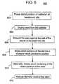
- FIG. 6is a flowchart of method 600 for treating vascular abnormalities using a stent.
- the methodincludes selecting a stent comprising a polymeric material, and delivering the stent to the treatment site using a delivery catheter, as shown in Block 602 .
- the stentis mounted on the delivery catheter in a compressed configuration on a balloon.
- the distal portion of the delivery catheteris inserted into the vascular system of the patient, and advanced through the vascular system to the treatment site.
- the stentWhen the stent is positioned across the vascular lesion to be treated, the stent is deployed from the catheter, as indicated in Block 604 . As the stent is deployed from the catheter, it is expanded (Block 606 ), causing the diameter of the stent to increase, pressing the exterior surface of the stent against the interior surface of the vascular wall, and lodging the stent firmly in place. As the stent is expanded, the crown portions of the stent move to a diameter recoil prevention position, as indicated in Block 608 . During expansion of the stent, the strut portions move laterally away from each other.
- the movable connector portionslongitudinally connected to both the strut portions and the crown portions of the stent, draw the crown portions toward the strut portions.
- the movable bifurcated connector portions attached to the strut portions and the crown portionsdeform based on the expansion of the stent, as illustrated in FIGS. 5A and 5B .
- the crown portions of the stenttranslate from a concave to a convex configuration in relation to the strut portions.
- the crown portions of the stentmay undergo strain hardening as a result of the expansion of the stent.
- the crown portions of the stentmove to a diameter recoil prevention position and reduce diameter recoil of the stent (Block 612 ) in response to the expansion of the stent.
- Diameter recoilmay be further reduced if the crown portions of the stent are subject to strain hardening in the expanded configuration.
Landscapes
- Health & Medical Sciences (AREA)
- Heart & Thoracic Surgery (AREA)
- Biomedical Technology (AREA)
- Vascular Medicine (AREA)
- Engineering & Computer Science (AREA)
- Life Sciences & Earth Sciences (AREA)
- Animal Behavior & Ethology (AREA)
- General Health & Medical Sciences (AREA)
- Public Health (AREA)
- Veterinary Medicine (AREA)
- Physics & Mathematics (AREA)
- Optics & Photonics (AREA)
- Epidemiology (AREA)
- Surgery (AREA)
- Cardiology (AREA)
- Oral & Maxillofacial Surgery (AREA)
- Transplantation (AREA)
- Materials For Medical Uses (AREA)
- Prostheses (AREA)
- Media Introduction/Drainage Providing Device (AREA)
Abstract
Description
Claims (12)
Priority Applications (3)
| Application Number | Priority Date | Filing Date | Title |
|---|---|---|---|
| US11/379,161US8066760B2 (en) | 2006-04-18 | 2006-04-18 | Stent with movable crown |
| EP07780905AEP2012847A2 (en) | 2006-04-18 | 2007-03-29 | Stent with movable crown |
| PCT/US2007/065502WO2007121066A2 (en) | 2006-04-18 | 2007-03-29 | Stent with movable crown |
Applications Claiming Priority (1)
| Application Number | Priority Date | Filing Date | Title |
|---|---|---|---|
| US11/379,161US8066760B2 (en) | 2006-04-18 | 2006-04-18 | Stent with movable crown |
Publications (2)
| Publication Number | Publication Date |
|---|---|
| US20070244543A1 US20070244543A1 (en) | 2007-10-18 |
| US8066760B2true US8066760B2 (en) | 2011-11-29 |
Family
ID=38578426
Family Applications (1)
| Application Number | Title | Priority Date | Filing Date |
|---|---|---|---|
| US11/379,161Expired - Fee RelatedUS8066760B2 (en) | 2006-04-18 | 2006-04-18 | Stent with movable crown |
Country Status (3)
| Country | Link |
|---|---|
| US (1) | US8066760B2 (en) |
| EP (1) | EP2012847A2 (en) |
| WO (1) | WO2007121066A2 (en) |
Cited By (4)
| Publication number | Priority date | Publication date | Assignee | Title |
|---|---|---|---|---|
| WO2015168674A1 (en) | 2014-05-02 | 2015-11-05 | Research Institute At Nationwide Children's Hospital | Compositions and methods for anti-lyst immunomodulation |
| WO2016160012A1 (en) | 2015-04-01 | 2016-10-06 | Yale University | Iron platinum particles for adherence of biologics on medical implants |
| US10328182B2 (en) | 2013-05-14 | 2019-06-25 | University Of Georgia Research Foundation, Inc. | Compositions and methods for reducing neointima formation |
| US11541149B2 (en) | 2015-12-11 | 2023-01-03 | Research Institute At Nationwide Children's Hospital | Systems and methods for optimized patient specific tissue engineering vascular grafts |
Families Citing this family (40)
| Publication number | Priority date | Publication date | Assignee | Title |
|---|---|---|---|---|
| DE102005003632A1 (en) | 2005-01-20 | 2006-08-17 | Fraunhofer-Gesellschaft zur Förderung der angewandten Forschung e.V. | Catheter for the transvascular implantation of heart valve prostheses |
| EP2364676B1 (en)* | 2005-06-30 | 2018-12-19 | Abbott Laboratories | Endoprosthesis having foot extensions |
| US20070213813A1 (en) | 2005-12-22 | 2007-09-13 | Symetis Sa | Stent-valves for valve replacement and associated methods and systems for surgery |
| ES2624595T3 (en) | 2007-03-05 | 2017-07-17 | Endospan Ltd | Bifurcated, supportive, expandable endoluminal grafts with multiple components and methods for use |
| US7896915B2 (en) | 2007-04-13 | 2011-03-01 | Jenavalve Technology, Inc. | Medical device for treating a heart valve insufficiency |
| EP2679198B1 (en) | 2007-10-25 | 2021-03-24 | Symetis SA | Valved-stents and systems for delivery thereof |
| CN101965162B (en) | 2007-12-15 | 2014-12-10 | 恩多斯潘有限公司 | Extra-vascular wrapping for treating aneurysmatic aorta in conjunction with endovascular stent-graft and methods thereof |
| BR112012021347A2 (en) | 2008-02-26 | 2019-09-24 | Jenavalve Tecnology Inc | stent for positioning and anchoring a valve prosthesis at an implantation site in a patient's heart |
| US9044318B2 (en) | 2008-02-26 | 2015-06-02 | Jenavalve Technology Gmbh | Stent for the positioning and anchoring of a valvular prosthesis |
| CA3009244C (en) | 2009-06-23 | 2020-04-28 | Endospan Ltd. | Vascular prostheses for treating aneurysms |
| WO2011004374A1 (en) | 2009-07-09 | 2011-01-13 | Endospan Ltd. | Apparatus for closure of a lumen and methods of using the same |
| CN102740807B (en) | 2009-11-30 | 2015-11-25 | 恩多斯潘有限公司 | Multi-component stent-graft system for implantation into vessels with multiple branches |
| EP2509535B1 (en) | 2009-12-08 | 2016-12-07 | Endospan Ltd | Endovascular stent-graft system with fenestrated and crossing stent-grafts |
| WO2011080738A1 (en) | 2009-12-31 | 2011-07-07 | Endospan Ltd. | Endovascular flow direction indicator |
| US9468517B2 (en) | 2010-02-08 | 2016-10-18 | Endospan Ltd. | Thermal energy application for prevention and management of endoleaks in stent-grafts |
| US20110282428A1 (en)* | 2010-05-13 | 2011-11-17 | Boston Scientific Scimed, Inc. | Biodegradable composite stent |
| US10856978B2 (en) | 2010-05-20 | 2020-12-08 | Jenavalve Technology, Inc. | Catheter system |
| WO2011147849A1 (en) | 2010-05-25 | 2011-12-01 | Jenavalve Technology Inc. | Prosthetic heart valve and transcatheter delivered endoprosthesis comprising a prosthetic heart valve and a stent |
| CA2826022A1 (en) | 2011-02-03 | 2012-08-09 | Endospan Ltd. | Implantable medical devices constructed of shape memory material |
| WO2012111006A1 (en) | 2011-02-17 | 2012-08-23 | Endospan Ltd. | Vascular bands and delivery systems therefor |
| GB2488165B (en) | 2011-02-18 | 2013-08-07 | Cook Medical Technologies Llc | Prosthesis and method of manufacturing the same |
| WO2012117395A1 (en) | 2011-03-02 | 2012-09-07 | Endospan Ltd. | Reduced-strain extra- vascular ring for treating aortic aneurysm |
| US8574287B2 (en) | 2011-06-14 | 2013-11-05 | Endospan Ltd. | Stents incorporating a plurality of strain-distribution locations |
| US8951298B2 (en) | 2011-06-21 | 2015-02-10 | Endospan Ltd. | Endovascular system with circumferentially-overlapping stent-grafts |
| US9254209B2 (en) | 2011-07-07 | 2016-02-09 | Endospan Ltd. | Stent fixation with reduced plastic deformation |
| US9839510B2 (en) | 2011-08-28 | 2017-12-12 | Endospan Ltd. | Stent-grafts with post-deployment variable radial displacement |
| US9427339B2 (en) | 2011-10-30 | 2016-08-30 | Endospan Ltd. | Triple-collar stent-graft |
| US9597204B2 (en) | 2011-12-04 | 2017-03-21 | Endospan Ltd. | Branched stent-graft system |
| WO2013171730A1 (en) | 2012-05-15 | 2013-11-21 | Endospan Ltd. | Stent-graft with fixation elements that are radially confined for delivery |
| US9993360B2 (en) | 2013-01-08 | 2018-06-12 | Endospan Ltd. | Minimization of stent-graft migration during implantation |
| US9668892B2 (en) | 2013-03-11 | 2017-06-06 | Endospan Ltd. | Multi-component stent-graft system for aortic dissections |
| CN105491978A (en) | 2013-08-30 | 2016-04-13 | 耶拿阀门科技股份有限公司 | Radially collapsible frame for a prosthetic valve and method for manufacturing such a frame |
| WO2015075708A1 (en) | 2013-11-19 | 2015-05-28 | Endospan Ltd. | Stent system with radial-expansion locking |
| US20150328373A1 (en)* | 2014-05-19 | 2015-11-19 | Abbott Cardiovascular Systems Inc. | Additives To Increase Degradation Rate Of A Biodegradable Scaffolding And Methods Of Forming Same |
| CN106029005B (en) | 2014-12-18 | 2018-01-19 | 恩都思潘有限公司 | The Endovascular stent-graft of horizontal conduit with tired resistance |
| EP3270825B1 (en) | 2015-03-20 | 2020-04-22 | JenaValve Technology, Inc. | Heart valve prosthesis delivery system |
| US10709555B2 (en) | 2015-05-01 | 2020-07-14 | Jenavalve Technology, Inc. | Device and method with reduced pacemaker rate in heart valve replacement |
| WO2017195125A1 (en) | 2016-05-13 | 2017-11-16 | Jenavalve Technology, Inc. | Heart valve prosthesis delivery system and method for delivery of heart valve prosthesis with introducer sheath and loading system |
| WO2018138658A1 (en) | 2017-01-27 | 2018-08-02 | Jenavalve Technology, Inc. | Heart valve mimicry |
| WO2024102411A1 (en) | 2022-11-09 | 2024-05-16 | Jenavalve Technology, Inc. | Catheter system for sequential deployment of an expandable implant |
Citations (15)
| Publication number | Priority date | Publication date | Assignee | Title |
|---|---|---|---|---|
| US5441515A (en)* | 1993-04-23 | 1995-08-15 | Advanced Cardiovascular Systems, Inc. | Ratcheting stent |
| US5776181A (en)* | 1995-07-25 | 1998-07-07 | Medstent Inc. | Expandable stent |
| US6019789A (en)* | 1998-04-01 | 2000-02-01 | Quanam Medical Corporation | Expandable unit cell and intraluminal stent |
| US6027527A (en)* | 1996-12-06 | 2000-02-22 | Piolax Inc. | Stent |
| US6231598B1 (en)* | 1997-09-24 | 2001-05-15 | Med Institute, Inc. | Radially expandable stent |
| US6293967B1 (en)* | 1998-10-29 | 2001-09-25 | Conor Medsystems, Inc. | Expandable medical device with ductile hinges |
| US6295714B1 (en)* | 1997-04-15 | 2001-10-02 | Schneider (Usa) Inc | Process for fabricating a prosthesis |
| US20030199970A1 (en)* | 1998-03-30 | 2003-10-23 | Conor Medsystems, Inc. | Expandable medical device for delivery of beneficial agent |
| US20040102837A1 (en)* | 2002-11-25 | 2004-05-27 | Boyle Christopher T. | Implantable expandable medical devices having regions of differential mechanical properties and methods of making same |
| US6773455B2 (en)* | 1997-06-24 | 2004-08-10 | Advanced Cardiovascular Systems, Inc. | Stent with reinforced struts and bimodal deployment |
| US20050149111A1 (en)* | 2003-12-26 | 2005-07-07 | Terumo Kabushiki Kaisha | Embolus member capturing device and embolus member capturing device leaving implement |
| US20050182474A1 (en) | 2004-02-13 | 2005-08-18 | Medtronic Vascular, Inc. | Coated stent having protruding crowns and elongated struts |
| WO2006005027A2 (en) | 2004-06-30 | 2006-01-12 | Cordis Corporation | Intraluminal medical device having asymetrical members |
| EP1645300A1 (en) | 2004-10-08 | 2006-04-12 | Cordis Corporation | Improved geometry and non-metallic material for controlled recoil stent |
| US7291166B2 (en)* | 2005-05-18 | 2007-11-06 | Advanced Cardiovascular Systems, Inc. | Polymeric stent patterns |
- 2006
- 2006-04-18USUS11/379,161patent/US8066760B2/ennot_activeExpired - Fee Related
- 2007
- 2007-03-29WOPCT/US2007/065502patent/WO2007121066A2/enactiveApplication Filing
- 2007-03-29EPEP07780905Apatent/EP2012847A2/ennot_activeWithdrawn
Patent Citations (15)
| Publication number | Priority date | Publication date | Assignee | Title |
|---|---|---|---|---|
| US5441515A (en)* | 1993-04-23 | 1995-08-15 | Advanced Cardiovascular Systems, Inc. | Ratcheting stent |
| US5776181A (en)* | 1995-07-25 | 1998-07-07 | Medstent Inc. | Expandable stent |
| US6027527A (en)* | 1996-12-06 | 2000-02-22 | Piolax Inc. | Stent |
| US6295714B1 (en)* | 1997-04-15 | 2001-10-02 | Schneider (Usa) Inc | Process for fabricating a prosthesis |
| US6773455B2 (en)* | 1997-06-24 | 2004-08-10 | Advanced Cardiovascular Systems, Inc. | Stent with reinforced struts and bimodal deployment |
| US6231598B1 (en)* | 1997-09-24 | 2001-05-15 | Med Institute, Inc. | Radially expandable stent |
| US20030199970A1 (en)* | 1998-03-30 | 2003-10-23 | Conor Medsystems, Inc. | Expandable medical device for delivery of beneficial agent |
| US6019789A (en)* | 1998-04-01 | 2000-02-01 | Quanam Medical Corporation | Expandable unit cell and intraluminal stent |
| US6293967B1 (en)* | 1998-10-29 | 2001-09-25 | Conor Medsystems, Inc. | Expandable medical device with ductile hinges |
| US20040102837A1 (en)* | 2002-11-25 | 2004-05-27 | Boyle Christopher T. | Implantable expandable medical devices having regions of differential mechanical properties and methods of making same |
| US20050149111A1 (en)* | 2003-12-26 | 2005-07-07 | Terumo Kabushiki Kaisha | Embolus member capturing device and embolus member capturing device leaving implement |
| US20050182474A1 (en) | 2004-02-13 | 2005-08-18 | Medtronic Vascular, Inc. | Coated stent having protruding crowns and elongated struts |
| WO2006005027A2 (en) | 2004-06-30 | 2006-01-12 | Cordis Corporation | Intraluminal medical device having asymetrical members |
| EP1645300A1 (en) | 2004-10-08 | 2006-04-12 | Cordis Corporation | Improved geometry and non-metallic material for controlled recoil stent |
| US7291166B2 (en)* | 2005-05-18 | 2007-11-06 | Advanced Cardiovascular Systems, Inc. | Polymeric stent patterns |
Cited By (7)
| Publication number | Priority date | Publication date | Assignee | Title |
|---|---|---|---|---|
| US10328182B2 (en) | 2013-05-14 | 2019-06-25 | University Of Georgia Research Foundation, Inc. | Compositions and methods for reducing neointima formation |
| US11246965B2 (en) | 2013-05-14 | 2022-02-15 | University Of Georgia Research Foundation, Inc. | Compositions and methods for reducing neointima formation |
| WO2015168674A1 (en) | 2014-05-02 | 2015-11-05 | Research Institute At Nationwide Children's Hospital | Compositions and methods for anti-lyst immunomodulation |
| WO2016160012A1 (en) | 2015-04-01 | 2016-10-06 | Yale University | Iron platinum particles for adherence of biologics on medical implants |
| US11285211B2 (en) | 2015-04-01 | 2022-03-29 | Yale University | Iron platinum particles for adherence of biologics on medical implants |
| US11541149B2 (en) | 2015-12-11 | 2023-01-03 | Research Institute At Nationwide Children's Hospital | Systems and methods for optimized patient specific tissue engineering vascular grafts |
| US12115282B2 (en) | 2015-12-11 | 2024-10-15 | Research Institute At Nationwide Children's Hospital | Systems and methods for optimized patient specific tissue engineering vascular grafts |
Also Published As
| Publication number | Publication date |
|---|---|
| WO2007121066A2 (en) | 2007-10-25 |
| WO2007121066A3 (en) | 2007-12-27 |
| EP2012847A2 (en) | 2009-01-14 |
| US20070244543A1 (en) | 2007-10-18 |
Similar Documents
| Publication | Publication Date | Title |
|---|---|---|
| US8066760B2 (en) | Stent with movable crown | |
| US5282823A (en) | Intravascular radially expandable stent | |
| US7771464B2 (en) | Overlapping coated stents method | |
| US7540880B2 (en) | Differentially coated stent | |
| EP1635735B1 (en) | System for treating an ostium of a side-branch vessle | |
| US20090093871A1 (en) | Medical Implant With Internal Drug Delivery System | |
| US20100125326A1 (en) | Braided Stent With a Shortenable Tether | |
| US20040230176A1 (en) | System for treating a vascular condition that inhibits restenosis at stent ends | |
| US20050021128A1 (en) | Compliant, porous, rolled stent | |
| US20070129793A1 (en) | Expandable biodegradable polymeric stents for combined mechanical support and pharmacological or radiation therapy | |
| US9814610B2 (en) | Stent with elongating struts | |
| US20100070013A1 (en) | Medical Device With Microsphere Drug Delivery System | |
| US20080249599A1 (en) | Stent With Therapeutic Agent Delivery Structures in Low Strain Regions | |
| WO2005102218A1 (en) | Method and system for stent retention using an adhesive | |
| US20060210600A1 (en) | Coated stent with timed release of multiple therapeutic agents to inhibit restenosis adjacent to the stent ends | |
| US20090093869A1 (en) | Medical device with curved struts | |
| EP1472992A1 (en) | A method and system for improving stent retention using stent openings | |
| US9358139B2 (en) | Expandable devices |
Legal Events
| Date | Code | Title | Description |
|---|---|---|---|
| AS | Assignment | Owner name:MEDTRONIC VASCULAR, INC., CALIFORNIA Free format text:ASSIGNMENT OF ASSIGNORS INTEREST;ASSIGNOR:MITCHELL, JAMES;REEL/FRAME:017579/0617 Effective date:20060427 | |
| ZAAA | Notice of allowance and fees due | Free format text:ORIGINAL CODE: NOA | |
| ZAAB | Notice of allowance mailed | Free format text:ORIGINAL CODE: MN/=. | |
| STCF | Information on status: patent grant | Free format text:PATENTED CASE | |
| FPAY | Fee payment | Year of fee payment:4 | |
| MAFP | Maintenance fee payment | Free format text:PAYMENT OF MAINTENANCE FEE, 8TH YEAR, LARGE ENTITY (ORIGINAL EVENT CODE: M1552); ENTITY STATUS OF PATENT OWNER: LARGE ENTITY Year of fee payment:8 | |
| FEPP | Fee payment procedure | Free format text:MAINTENANCE FEE REMINDER MAILED (ORIGINAL EVENT CODE: REM.); ENTITY STATUS OF PATENT OWNER: LARGE ENTITY | |
| LAPS | Lapse for failure to pay maintenance fees | Free format text:PATENT EXPIRED FOR FAILURE TO PAY MAINTENANCE FEES (ORIGINAL EVENT CODE: EXP.); ENTITY STATUS OF PATENT OWNER: LARGE ENTITY | |
| STCH | Information on status: patent discontinuation | Free format text:PATENT EXPIRED DUE TO NONPAYMENT OF MAINTENANCE FEES UNDER 37 CFR 1.362 | |
| FP | Lapsed due to failure to pay maintenance fee | Effective date:20231129 |