US8066749B2 - Implant for stabilizing a bone graft during spinal fusion - Google Patents
Implant for stabilizing a bone graft during spinal fusionDownload PDFInfo
- Publication number
- US8066749B2 US8066749B2US11/304,202US30420205AUS8066749B2US 8066749 B2US8066749 B2US 8066749B2US 30420205 AUS30420205 AUS 30420205AUS 8066749 B2US8066749 B2US 8066749B2
- Authority
- US
- United States
- Prior art keywords
- plate
- anchoring
- intervertebral
- locking
- anchoring plate
- Prior art date
- Legal status (The legal status is an assumption and is not a legal conclusion. Google has not performed a legal analysis and makes no representation as to the accuracy of the status listed.)
- Expired - Fee Related, expires
Links
Images


Classifications
- A—HUMAN NECESSITIES
- A61—MEDICAL OR VETERINARY SCIENCE; HYGIENE
- A61B—DIAGNOSIS; SURGERY; IDENTIFICATION
- A61B17/00—Surgical instruments, devices or methods
- A61B17/02—Surgical instruments, devices or methods for holding wounds open, e.g. retractors; Tractors
- A61B17/025—Joint distractors
- A—HUMAN NECESSITIES
- A61—MEDICAL OR VETERINARY SCIENCE; HYGIENE
- A61B—DIAGNOSIS; SURGERY; IDENTIFICATION
- A61B17/00—Surgical instruments, devices or methods
- A61B17/56—Surgical instruments or methods for treatment of bones or joints; Devices specially adapted therefor
- A61B17/58—Surgical instruments or methods for treatment of bones or joints; Devices specially adapted therefor for osteosynthesis, e.g. bone plates, screws or setting implements
- A61B17/68—Internal fixation devices, including fasteners and spinal fixators, even if a part thereof projects from the skin
- A61B17/70—Spinal positioners or stabilisers, e.g. stabilisers comprising fluid filler in an implant
- A61B17/7059—Cortical plates
- A—HUMAN NECESSITIES
- A61—MEDICAL OR VETERINARY SCIENCE; HYGIENE
- A61B—DIAGNOSIS; SURGERY; IDENTIFICATION
- A61B17/00—Surgical instruments, devices or methods
- A61B17/56—Surgical instruments or methods for treatment of bones or joints; Devices specially adapted therefor
- A61B17/58—Surgical instruments or methods for treatment of bones or joints; Devices specially adapted therefor for osteosynthesis, e.g. bone plates, screws or setting implements
- A61B17/68—Internal fixation devices, including fasteners and spinal fixators, even if a part thereof projects from the skin
- A61B17/80—Cortical plates, i.e. bone plates; Instruments for holding or positioning cortical plates, or for compressing bones attached to cortical plates
- A61B17/8033—Cortical plates, i.e. bone plates; Instruments for holding or positioning cortical plates, or for compressing bones attached to cortical plates having indirect contact with screw heads, or having contact with screw heads maintained with the aid of additional components, e.g. nuts, wedges or head covers
- A61B17/8042—Cortical plates, i.e. bone plates; Instruments for holding or positioning cortical plates, or for compressing bones attached to cortical plates having indirect contact with screw heads, or having contact with screw heads maintained with the aid of additional components, e.g. nuts, wedges or head covers the additional component being a cover over the screw head
- A—HUMAN NECESSITIES
- A61—MEDICAL OR VETERINARY SCIENCE; HYGIENE
- A61F—FILTERS IMPLANTABLE INTO BLOOD VESSELS; PROSTHESES; DEVICES PROVIDING PATENCY TO, OR PREVENTING COLLAPSING OF, TUBULAR STRUCTURES OF THE BODY, e.g. STENTS; ORTHOPAEDIC, NURSING OR CONTRACEPTIVE DEVICES; FOMENTATION; TREATMENT OR PROTECTION OF EYES OR EARS; BANDAGES, DRESSINGS OR ABSORBENT PADS; FIRST-AID KITS
- A61F2/00—Filters implantable into blood vessels; Prostheses, i.e. artificial substitutes or replacements for parts of the body; Appliances for connecting them with the body; Devices providing patency to, or preventing collapsing of, tubular structures of the body, e.g. stents
- A61F2/02—Prostheses implantable into the body
- A61F2/30—Joints
- A61F2/44—Joints for the spine, e.g. vertebrae, spinal discs
- A61F2/4405—Joints for the spine, e.g. vertebrae, spinal discs for apophyseal or facet joints, i.e. between adjacent spinous or transverse processes
- A—HUMAN NECESSITIES
- A61—MEDICAL OR VETERINARY SCIENCE; HYGIENE
- A61F—FILTERS IMPLANTABLE INTO BLOOD VESSELS; PROSTHESES; DEVICES PROVIDING PATENCY TO, OR PREVENTING COLLAPSING OF, TUBULAR STRUCTURES OF THE BODY, e.g. STENTS; ORTHOPAEDIC, NURSING OR CONTRACEPTIVE DEVICES; FOMENTATION; TREATMENT OR PROTECTION OF EYES OR EARS; BANDAGES, DRESSINGS OR ABSORBENT PADS; FIRST-AID KITS
- A61F2/00—Filters implantable into blood vessels; Prostheses, i.e. artificial substitutes or replacements for parts of the body; Appliances for connecting them with the body; Devices providing patency to, or preventing collapsing of, tubular structures of the body, e.g. stents
- A61F2/02—Prostheses implantable into the body
- A61F2/30—Joints
- A61F2/44—Joints for the spine, e.g. vertebrae, spinal discs
- A61F2/4455—Joints for the spine, e.g. vertebrae, spinal discs for the fusion of spinal bodies, e.g. intervertebral fusion of adjacent spinal bodies, e.g. fusion cages
- A—HUMAN NECESSITIES
- A61—MEDICAL OR VETERINARY SCIENCE; HYGIENE
- A61F—FILTERS IMPLANTABLE INTO BLOOD VESSELS; PROSTHESES; DEVICES PROVIDING PATENCY TO, OR PREVENTING COLLAPSING OF, TUBULAR STRUCTURES OF THE BODY, e.g. STENTS; ORTHOPAEDIC, NURSING OR CONTRACEPTIVE DEVICES; FOMENTATION; TREATMENT OR PROTECTION OF EYES OR EARS; BANDAGES, DRESSINGS OR ABSORBENT PADS; FIRST-AID KITS
- A61F2/00—Filters implantable into blood vessels; Prostheses, i.e. artificial substitutes or replacements for parts of the body; Appliances for connecting them with the body; Devices providing patency to, or preventing collapsing of, tubular structures of the body, e.g. stents
- A61F2/02—Prostheses implantable into the body
- A61F2/30—Joints
- A61F2/46—Special tools for implanting artificial joints
- A61F2/4603—Special tools for implanting artificial joints for insertion or extraction of endoprosthetic joints or of accessories thereof
- A61F2/4611—Special tools for implanting artificial joints for insertion or extraction of endoprosthetic joints or of accessories thereof of spinal prostheses
- A—HUMAN NECESSITIES
- A61—MEDICAL OR VETERINARY SCIENCE; HYGIENE
- A61F—FILTERS IMPLANTABLE INTO BLOOD VESSELS; PROSTHESES; DEVICES PROVIDING PATENCY TO, OR PREVENTING COLLAPSING OF, TUBULAR STRUCTURES OF THE BODY, e.g. STENTS; ORTHOPAEDIC, NURSING OR CONTRACEPTIVE DEVICES; FOMENTATION; TREATMENT OR PROTECTION OF EYES OR EARS; BANDAGES, DRESSINGS OR ABSORBENT PADS; FIRST-AID KITS
- A61F2/00—Filters implantable into blood vessels; Prostheses, i.e. artificial substitutes or replacements for parts of the body; Appliances for connecting them with the body; Devices providing patency to, or preventing collapsing of, tubular structures of the body, e.g. stents
- A61F2/02—Prostheses implantable into the body
- A61F2/30—Joints
- A61F2/46—Special tools for implanting artificial joints
- A61F2/4684—Trial or dummy prostheses
- A—HUMAN NECESSITIES
- A61—MEDICAL OR VETERINARY SCIENCE; HYGIENE
- A61B—DIAGNOSIS; SURGERY; IDENTIFICATION
- A61B17/00—Surgical instruments, devices or methods
- A61B17/56—Surgical instruments or methods for treatment of bones or joints; Devices specially adapted therefor
- A61B17/562—Implants for placement in joint gaps without restricting joint motion, e.g. to reduce arthritic pain
- A—HUMAN NECESSITIES
- A61—MEDICAL OR VETERINARY SCIENCE; HYGIENE
- A61B—DIAGNOSIS; SURGERY; IDENTIFICATION
- A61B17/00—Surgical instruments, devices or methods
- A61B17/56—Surgical instruments or methods for treatment of bones or joints; Devices specially adapted therefor
- A61B17/58—Surgical instruments or methods for treatment of bones or joints; Devices specially adapted therefor for osteosynthesis, e.g. bone plates, screws or setting implements
- A61B17/68—Internal fixation devices, including fasteners and spinal fixators, even if a part thereof projects from the skin
- A61B17/70—Spinal positioners or stabilisers, e.g. stabilisers comprising fluid filler in an implant
- A61B17/7062—Devices acting on, attached to, or simulating the effect of, vertebral processes, vertebral facets or ribs ; Tools for such devices
- A61B17/7064—Devices acting on, attached to, or simulating the effect of, vertebral facets; Tools therefor
- A—HUMAN NECESSITIES
- A61—MEDICAL OR VETERINARY SCIENCE; HYGIENE
- A61B—DIAGNOSIS; SURGERY; IDENTIFICATION
- A61B17/00—Surgical instruments, devices or methods
- A61B17/56—Surgical instruments or methods for treatment of bones or joints; Devices specially adapted therefor
- A61B17/58—Surgical instruments or methods for treatment of bones or joints; Devices specially adapted therefor for osteosynthesis, e.g. bone plates, screws or setting implements
- A61B17/68—Internal fixation devices, including fasteners and spinal fixators, even if a part thereof projects from the skin
- A61B17/70—Spinal positioners or stabilisers, e.g. stabilisers comprising fluid filler in an implant
- A61B17/7071—Implants for expanding or repairing the vertebral arch or wedged between laminae or pedicles; Tools therefor
- A—HUMAN NECESSITIES
- A61—MEDICAL OR VETERINARY SCIENCE; HYGIENE
- A61B—DIAGNOSIS; SURGERY; IDENTIFICATION
- A61B17/00—Surgical instruments, devices or methods
- A61B17/56—Surgical instruments or methods for treatment of bones or joints; Devices specially adapted therefor
- A61B17/58—Surgical instruments or methods for treatment of bones or joints; Devices specially adapted therefor for osteosynthesis, e.g. bone plates, screws or setting implements
- A61B17/68—Internal fixation devices, including fasteners and spinal fixators, even if a part thereof projects from the skin
- A61B17/84—Fasteners therefor or fasteners being internal fixation devices
- A61B17/86—Pins or screws or threaded wires; nuts therefor
- A61B17/8625—Shanks, i.e. parts contacting bone tissue
- A61B17/8635—Tips of screws
- A—HUMAN NECESSITIES
- A61—MEDICAL OR VETERINARY SCIENCE; HYGIENE
- A61B—DIAGNOSIS; SURGERY; IDENTIFICATION
- A61B17/00—Surgical instruments, devices or methods
- A61B17/02—Surgical instruments, devices or methods for holding wounds open, e.g. retractors; Tractors
- A61B17/025—Joint distractors
- A61B2017/0256—Joint distractors for the spine
- A—HUMAN NECESSITIES
- A61—MEDICAL OR VETERINARY SCIENCE; HYGIENE
- A61B—DIAGNOSIS; SURGERY; IDENTIFICATION
- A61B17/00—Surgical instruments, devices or methods
- A61B17/56—Surgical instruments or methods for treatment of bones or joints; Devices specially adapted therefor
- A61B17/58—Surgical instruments or methods for treatment of bones or joints; Devices specially adapted therefor for osteosynthesis, e.g. bone plates, screws or setting implements
- A61B17/68—Internal fixation devices, including fasteners and spinal fixators, even if a part thereof projects from the skin
- A61B17/84—Fasteners therefor or fasteners being internal fixation devices
- A61B17/86—Pins or screws or threaded wires; nuts therefor
- A61B2017/8655—Pins or screws or threaded wires; nuts therefor with special features for locking in the bone
- A—HUMAN NECESSITIES
- A61—MEDICAL OR VETERINARY SCIENCE; HYGIENE
- A61B—DIAGNOSIS; SURGERY; IDENTIFICATION
- A61B90/00—Instruments, implements or accessories specially adapted for surgery or diagnosis and not covered by any of the groups A61B1/00 - A61B50/00, e.g. for luxation treatment or for protecting wound edges
- A61B90/06—Measuring instruments not otherwise provided for
- A61B2090/061—Measuring instruments not otherwise provided for for measuring dimensions, e.g. length
- A—HUMAN NECESSITIES
- A61—MEDICAL OR VETERINARY SCIENCE; HYGIENE
- A61F—FILTERS IMPLANTABLE INTO BLOOD VESSELS; PROSTHESES; DEVICES PROVIDING PATENCY TO, OR PREVENTING COLLAPSING OF, TUBULAR STRUCTURES OF THE BODY, e.g. STENTS; ORTHOPAEDIC, NURSING OR CONTRACEPTIVE DEVICES; FOMENTATION; TREATMENT OR PROTECTION OF EYES OR EARS; BANDAGES, DRESSINGS OR ABSORBENT PADS; FIRST-AID KITS
- A61F2/00—Filters implantable into blood vessels; Prostheses, i.e. artificial substitutes or replacements for parts of the body; Appliances for connecting them with the body; Devices providing patency to, or preventing collapsing of, tubular structures of the body, e.g. stents
- A61F2/02—Prostheses implantable into the body
- A61F2/28—Bones
- A—HUMAN NECESSITIES
- A61—MEDICAL OR VETERINARY SCIENCE; HYGIENE
- A61F—FILTERS IMPLANTABLE INTO BLOOD VESSELS; PROSTHESES; DEVICES PROVIDING PATENCY TO, OR PREVENTING COLLAPSING OF, TUBULAR STRUCTURES OF THE BODY, e.g. STENTS; ORTHOPAEDIC, NURSING OR CONTRACEPTIVE DEVICES; FOMENTATION; TREATMENT OR PROTECTION OF EYES OR EARS; BANDAGES, DRESSINGS OR ABSORBENT PADS; FIRST-AID KITS
- A61F2/00—Filters implantable into blood vessels; Prostheses, i.e. artificial substitutes or replacements for parts of the body; Appliances for connecting them with the body; Devices providing patency to, or preventing collapsing of, tubular structures of the body, e.g. stents
- A61F2/02—Prostheses implantable into the body
- A61F2/30—Joints
- A61F2/30767—Special external or bone-contacting surface, e.g. coating for improving bone ingrowth
- A61F2/30771—Special external or bone-contacting surface, e.g. coating for improving bone ingrowth applied in original prostheses, e.g. holes or grooves
- A—HUMAN NECESSITIES
- A61—MEDICAL OR VETERINARY SCIENCE; HYGIENE
- A61F—FILTERS IMPLANTABLE INTO BLOOD VESSELS; PROSTHESES; DEVICES PROVIDING PATENCY TO, OR PREVENTING COLLAPSING OF, TUBULAR STRUCTURES OF THE BODY, e.g. STENTS; ORTHOPAEDIC, NURSING OR CONTRACEPTIVE DEVICES; FOMENTATION; TREATMENT OR PROTECTION OF EYES OR EARS; BANDAGES, DRESSINGS OR ABSORBENT PADS; FIRST-AID KITS
- A61F2/00—Filters implantable into blood vessels; Prostheses, i.e. artificial substitutes or replacements for parts of the body; Appliances for connecting them with the body; Devices providing patency to, or preventing collapsing of, tubular structures of the body, e.g. stents
- A61F2/02—Prostheses implantable into the body
- A61F2/30—Joints
- A61F2002/30001—Additional features of subject-matter classified in A61F2/28, A61F2/30 and subgroups thereof
- A61F2002/30003—Material related properties of the prosthesis or of a coating on the prosthesis
- A61F2002/3006—Properties of materials and coating materials
- A61F2002/30079—Properties of materials and coating materials magnetic
- A—HUMAN NECESSITIES
- A61—MEDICAL OR VETERINARY SCIENCE; HYGIENE
- A61F—FILTERS IMPLANTABLE INTO BLOOD VESSELS; PROSTHESES; DEVICES PROVIDING PATENCY TO, OR PREVENTING COLLAPSING OF, TUBULAR STRUCTURES OF THE BODY, e.g. STENTS; ORTHOPAEDIC, NURSING OR CONTRACEPTIVE DEVICES; FOMENTATION; TREATMENT OR PROTECTION OF EYES OR EARS; BANDAGES, DRESSINGS OR ABSORBENT PADS; FIRST-AID KITS
- A61F2/00—Filters implantable into blood vessels; Prostheses, i.e. artificial substitutes or replacements for parts of the body; Appliances for connecting them with the body; Devices providing patency to, or preventing collapsing of, tubular structures of the body, e.g. stents
- A61F2/02—Prostheses implantable into the body
- A61F2/30—Joints
- A61F2002/30001—Additional features of subject-matter classified in A61F2/28, A61F2/30 and subgroups thereof
- A61F2002/30003—Material related properties of the prosthesis or of a coating on the prosthesis
- A61F2002/3006—Properties of materials and coating materials
- A61F2002/30092—Properties of materials and coating materials using shape memory or superelastic materials, e.g. nitinol
- A—HUMAN NECESSITIES
- A61—MEDICAL OR VETERINARY SCIENCE; HYGIENE
- A61F—FILTERS IMPLANTABLE INTO BLOOD VESSELS; PROSTHESES; DEVICES PROVIDING PATENCY TO, OR PREVENTING COLLAPSING OF, TUBULAR STRUCTURES OF THE BODY, e.g. STENTS; ORTHOPAEDIC, NURSING OR CONTRACEPTIVE DEVICES; FOMENTATION; TREATMENT OR PROTECTION OF EYES OR EARS; BANDAGES, DRESSINGS OR ABSORBENT PADS; FIRST-AID KITS
- A61F2/00—Filters implantable into blood vessels; Prostheses, i.e. artificial substitutes or replacements for parts of the body; Appliances for connecting them with the body; Devices providing patency to, or preventing collapsing of, tubular structures of the body, e.g. stents
- A61F2/02—Prostheses implantable into the body
- A61F2/30—Joints
- A61F2002/30001—Additional features of subject-matter classified in A61F2/28, A61F2/30 and subgroups thereof
- A61F2002/30108—Shapes
- A61F2002/3011—Cross-sections or two-dimensional shapes
- A61F2002/30112—Rounded shapes, e.g. with rounded corners
- A61F2002/3013—Rounded shapes, e.g. with rounded corners figure-"8"- or hourglass-shaped
- A—HUMAN NECESSITIES
- A61—MEDICAL OR VETERINARY SCIENCE; HYGIENE
- A61F—FILTERS IMPLANTABLE INTO BLOOD VESSELS; PROSTHESES; DEVICES PROVIDING PATENCY TO, OR PREVENTING COLLAPSING OF, TUBULAR STRUCTURES OF THE BODY, e.g. STENTS; ORTHOPAEDIC, NURSING OR CONTRACEPTIVE DEVICES; FOMENTATION; TREATMENT OR PROTECTION OF EYES OR EARS; BANDAGES, DRESSINGS OR ABSORBENT PADS; FIRST-AID KITS
- A61F2/00—Filters implantable into blood vessels; Prostheses, i.e. artificial substitutes or replacements for parts of the body; Appliances for connecting them with the body; Devices providing patency to, or preventing collapsing of, tubular structures of the body, e.g. stents
- A61F2/02—Prostheses implantable into the body
- A61F2/30—Joints
- A61F2002/30001—Additional features of subject-matter classified in A61F2/28, A61F2/30 and subgroups thereof
- A61F2002/30108—Shapes
- A61F2002/3011—Cross-sections or two-dimensional shapes
- A61F2002/30159—Concave polygonal shapes
- A61F2002/30176—V-shaped
- A—HUMAN NECESSITIES
- A61—MEDICAL OR VETERINARY SCIENCE; HYGIENE
- A61F—FILTERS IMPLANTABLE INTO BLOOD VESSELS; PROSTHESES; DEVICES PROVIDING PATENCY TO, OR PREVENTING COLLAPSING OF, TUBULAR STRUCTURES OF THE BODY, e.g. STENTS; ORTHOPAEDIC, NURSING OR CONTRACEPTIVE DEVICES; FOMENTATION; TREATMENT OR PROTECTION OF EYES OR EARS; BANDAGES, DRESSINGS OR ABSORBENT PADS; FIRST-AID KITS
- A61F2/00—Filters implantable into blood vessels; Prostheses, i.e. artificial substitutes or replacements for parts of the body; Appliances for connecting them with the body; Devices providing patency to, or preventing collapsing of, tubular structures of the body, e.g. stents
- A61F2/02—Prostheses implantable into the body
- A61F2/30—Joints
- A61F2002/30001—Additional features of subject-matter classified in A61F2/28, A61F2/30 and subgroups thereof
- A61F2002/30108—Shapes
- A61F2002/30199—Three-dimensional shapes
- A61F2002/30308—Three-dimensional shapes banana-shaped
- A—HUMAN NECESSITIES
- A61—MEDICAL OR VETERINARY SCIENCE; HYGIENE
- A61F—FILTERS IMPLANTABLE INTO BLOOD VESSELS; PROSTHESES; DEVICES PROVIDING PATENCY TO, OR PREVENTING COLLAPSING OF, TUBULAR STRUCTURES OF THE BODY, e.g. STENTS; ORTHOPAEDIC, NURSING OR CONTRACEPTIVE DEVICES; FOMENTATION; TREATMENT OR PROTECTION OF EYES OR EARS; BANDAGES, DRESSINGS OR ABSORBENT PADS; FIRST-AID KITS
- A61F2/00—Filters implantable into blood vessels; Prostheses, i.e. artificial substitutes or replacements for parts of the body; Appliances for connecting them with the body; Devices providing patency to, or preventing collapsing of, tubular structures of the body, e.g. stents
- A61F2/02—Prostheses implantable into the body
- A61F2/30—Joints
- A61F2002/30001—Additional features of subject-matter classified in A61F2/28, A61F2/30 and subgroups thereof
- A61F2002/30316—The prosthesis having different structural features at different locations within the same prosthesis; Connections between prosthetic parts; Special structural features of bone or joint prostheses not otherwise provided for
- A61F2002/30329—Connections or couplings between prosthetic parts, e.g. between modular parts; Connecting elements
- A61F2002/30331—Connections or couplings between prosthetic parts, e.g. between modular parts; Connecting elements made by longitudinally pushing a protrusion into a complementarily-shaped recess, e.g. held by friction fit
- A61F2002/30378—Spherically-shaped protrusion and recess
- A—HUMAN NECESSITIES
- A61—MEDICAL OR VETERINARY SCIENCE; HYGIENE
- A61F—FILTERS IMPLANTABLE INTO BLOOD VESSELS; PROSTHESES; DEVICES PROVIDING PATENCY TO, OR PREVENTING COLLAPSING OF, TUBULAR STRUCTURES OF THE BODY, e.g. STENTS; ORTHOPAEDIC, NURSING OR CONTRACEPTIVE DEVICES; FOMENTATION; TREATMENT OR PROTECTION OF EYES OR EARS; BANDAGES, DRESSINGS OR ABSORBENT PADS; FIRST-AID KITS
- A61F2/00—Filters implantable into blood vessels; Prostheses, i.e. artificial substitutes or replacements for parts of the body; Appliances for connecting them with the body; Devices providing patency to, or preventing collapsing of, tubular structures of the body, e.g. stents
- A61F2/02—Prostheses implantable into the body
- A61F2/30—Joints
- A61F2002/30001—Additional features of subject-matter classified in A61F2/28, A61F2/30 and subgroups thereof
- A61F2002/30316—The prosthesis having different structural features at different locations within the same prosthesis; Connections between prosthetic parts; Special structural features of bone or joint prostheses not otherwise provided for
- A61F2002/30329—Connections or couplings between prosthetic parts, e.g. between modular parts; Connecting elements
- A61F2002/30383—Connections or couplings between prosthetic parts, e.g. between modular parts; Connecting elements made by laterally inserting a protrusion, e.g. a rib into a complementarily-shaped groove
- A—HUMAN NECESSITIES
- A61—MEDICAL OR VETERINARY SCIENCE; HYGIENE
- A61F—FILTERS IMPLANTABLE INTO BLOOD VESSELS; PROSTHESES; DEVICES PROVIDING PATENCY TO, OR PREVENTING COLLAPSING OF, TUBULAR STRUCTURES OF THE BODY, e.g. STENTS; ORTHOPAEDIC, NURSING OR CONTRACEPTIVE DEVICES; FOMENTATION; TREATMENT OR PROTECTION OF EYES OR EARS; BANDAGES, DRESSINGS OR ABSORBENT PADS; FIRST-AID KITS
- A61F2/00—Filters implantable into blood vessels; Prostheses, i.e. artificial substitutes or replacements for parts of the body; Appliances for connecting them with the body; Devices providing patency to, or preventing collapsing of, tubular structures of the body, e.g. stents
- A61F2/02—Prostheses implantable into the body
- A61F2/30—Joints
- A61F2002/30001—Additional features of subject-matter classified in A61F2/28, A61F2/30 and subgroups thereof
- A61F2002/30316—The prosthesis having different structural features at different locations within the same prosthesis; Connections between prosthetic parts; Special structural features of bone or joint prostheses not otherwise provided for
- A61F2002/30329—Connections or couplings between prosthetic parts, e.g. between modular parts; Connecting elements
- A61F2002/30462—Connections or couplings between prosthetic parts, e.g. between modular parts; Connecting elements retained or tied with a rope, string, thread, wire or cable
- A—HUMAN NECESSITIES
- A61—MEDICAL OR VETERINARY SCIENCE; HYGIENE
- A61F—FILTERS IMPLANTABLE INTO BLOOD VESSELS; PROSTHESES; DEVICES PROVIDING PATENCY TO, OR PREVENTING COLLAPSING OF, TUBULAR STRUCTURES OF THE BODY, e.g. STENTS; ORTHOPAEDIC, NURSING OR CONTRACEPTIVE DEVICES; FOMENTATION; TREATMENT OR PROTECTION OF EYES OR EARS; BANDAGES, DRESSINGS OR ABSORBENT PADS; FIRST-AID KITS
- A61F2/00—Filters implantable into blood vessels; Prostheses, i.e. artificial substitutes or replacements for parts of the body; Appliances for connecting them with the body; Devices providing patency to, or preventing collapsing of, tubular structures of the body, e.g. stents
- A61F2/02—Prostheses implantable into the body
- A61F2/30—Joints
- A61F2002/30001—Additional features of subject-matter classified in A61F2/28, A61F2/30 and subgroups thereof
- A61F2002/30316—The prosthesis having different structural features at different locations within the same prosthesis; Connections between prosthetic parts; Special structural features of bone or joint prostheses not otherwise provided for
- A61F2002/30329—Connections or couplings between prosthetic parts, e.g. between modular parts; Connecting elements
- A61F2002/30471—Connections or couplings between prosthetic parts, e.g. between modular parts; Connecting elements connected by a hinged linkage mechanism, e.g. of the single-bar or multi-bar linkage type
- A—HUMAN NECESSITIES
- A61—MEDICAL OR VETERINARY SCIENCE; HYGIENE
- A61F—FILTERS IMPLANTABLE INTO BLOOD VESSELS; PROSTHESES; DEVICES PROVIDING PATENCY TO, OR PREVENTING COLLAPSING OF, TUBULAR STRUCTURES OF THE BODY, e.g. STENTS; ORTHOPAEDIC, NURSING OR CONTRACEPTIVE DEVICES; FOMENTATION; TREATMENT OR PROTECTION OF EYES OR EARS; BANDAGES, DRESSINGS OR ABSORBENT PADS; FIRST-AID KITS
- A61F2/00—Filters implantable into blood vessels; Prostheses, i.e. artificial substitutes or replacements for parts of the body; Appliances for connecting them with the body; Devices providing patency to, or preventing collapsing of, tubular structures of the body, e.g. stents
- A61F2/02—Prostheses implantable into the body
- A61F2/30—Joints
- A61F2002/30001—Additional features of subject-matter classified in A61F2/28, A61F2/30 and subgroups thereof
- A61F2002/30316—The prosthesis having different structural features at different locations within the same prosthesis; Connections between prosthetic parts; Special structural features of bone or joint prostheses not otherwise provided for
- A61F2002/30329—Connections or couplings between prosthetic parts, e.g. between modular parts; Connecting elements
- A61F2002/30476—Connections or couplings between prosthetic parts, e.g. between modular parts; Connecting elements locked by an additional locking mechanism
- A61F2002/30517—Connections or couplings between prosthetic parts, e.g. between modular parts; Connecting elements locked by an additional locking mechanism using a locking plate
- A—HUMAN NECESSITIES
- A61—MEDICAL OR VETERINARY SCIENCE; HYGIENE
- A61F—FILTERS IMPLANTABLE INTO BLOOD VESSELS; PROSTHESES; DEVICES PROVIDING PATENCY TO, OR PREVENTING COLLAPSING OF, TUBULAR STRUCTURES OF THE BODY, e.g. STENTS; ORTHOPAEDIC, NURSING OR CONTRACEPTIVE DEVICES; FOMENTATION; TREATMENT OR PROTECTION OF EYES OR EARS; BANDAGES, DRESSINGS OR ABSORBENT PADS; FIRST-AID KITS
- A61F2/00—Filters implantable into blood vessels; Prostheses, i.e. artificial substitutes or replacements for parts of the body; Appliances for connecting them with the body; Devices providing patency to, or preventing collapsing of, tubular structures of the body, e.g. stents
- A61F2/02—Prostheses implantable into the body
- A61F2/30—Joints
- A61F2002/30001—Additional features of subject-matter classified in A61F2/28, A61F2/30 and subgroups thereof
- A61F2002/30316—The prosthesis having different structural features at different locations within the same prosthesis; Connections between prosthetic parts; Special structural features of bone or joint prostheses not otherwise provided for
- A61F2002/30329—Connections or couplings between prosthetic parts, e.g. between modular parts; Connecting elements
- A61F2002/30518—Connections or couplings between prosthetic parts, e.g. between modular parts; Connecting elements with possibility of relative movement between the prosthetic parts
- A61F2002/30528—Means for limiting said movement
- A—HUMAN NECESSITIES
- A61—MEDICAL OR VETERINARY SCIENCE; HYGIENE
- A61F—FILTERS IMPLANTABLE INTO BLOOD VESSELS; PROSTHESES; DEVICES PROVIDING PATENCY TO, OR PREVENTING COLLAPSING OF, TUBULAR STRUCTURES OF THE BODY, e.g. STENTS; ORTHOPAEDIC, NURSING OR CONTRACEPTIVE DEVICES; FOMENTATION; TREATMENT OR PROTECTION OF EYES OR EARS; BANDAGES, DRESSINGS OR ABSORBENT PADS; FIRST-AID KITS
- A61F2/00—Filters implantable into blood vessels; Prostheses, i.e. artificial substitutes or replacements for parts of the body; Appliances for connecting them with the body; Devices providing patency to, or preventing collapsing of, tubular structures of the body, e.g. stents
- A61F2/02—Prostheses implantable into the body
- A61F2/30—Joints
- A61F2002/30001—Additional features of subject-matter classified in A61F2/28, A61F2/30 and subgroups thereof
- A61F2002/30316—The prosthesis having different structural features at different locations within the same prosthesis; Connections between prosthetic parts; Special structural features of bone or joint prostheses not otherwise provided for
- A61F2002/30535—Special structural features of bone or joint prostheses not otherwise provided for
- A61F2002/30537—Special structural features of bone or joint prostheses not otherwise provided for adjustable
- A61F2002/30538—Special structural features of bone or joint prostheses not otherwise provided for adjustable for adjusting angular orientation
- A—HUMAN NECESSITIES
- A61—MEDICAL OR VETERINARY SCIENCE; HYGIENE
- A61F—FILTERS IMPLANTABLE INTO BLOOD VESSELS; PROSTHESES; DEVICES PROVIDING PATENCY TO, OR PREVENTING COLLAPSING OF, TUBULAR STRUCTURES OF THE BODY, e.g. STENTS; ORTHOPAEDIC, NURSING OR CONTRACEPTIVE DEVICES; FOMENTATION; TREATMENT OR PROTECTION OF EYES OR EARS; BANDAGES, DRESSINGS OR ABSORBENT PADS; FIRST-AID KITS
- A61F2/00—Filters implantable into blood vessels; Prostheses, i.e. artificial substitutes or replacements for parts of the body; Appliances for connecting them with the body; Devices providing patency to, or preventing collapsing of, tubular structures of the body, e.g. stents
- A61F2/02—Prostheses implantable into the body
- A61F2/30—Joints
- A61F2002/30001—Additional features of subject-matter classified in A61F2/28, A61F2/30 and subgroups thereof
- A61F2002/30316—The prosthesis having different structural features at different locations within the same prosthesis; Connections between prosthetic parts; Special structural features of bone or joint prostheses not otherwise provided for
- A61F2002/30535—Special structural features of bone or joint prostheses not otherwise provided for
- A61F2002/30563—Special structural features of bone or joint prostheses not otherwise provided for having elastic means or damping means, different from springs, e.g. including an elastomeric core or shock absorbers
- A—HUMAN NECESSITIES
- A61—MEDICAL OR VETERINARY SCIENCE; HYGIENE
- A61F—FILTERS IMPLANTABLE INTO BLOOD VESSELS; PROSTHESES; DEVICES PROVIDING PATENCY TO, OR PREVENTING COLLAPSING OF, TUBULAR STRUCTURES OF THE BODY, e.g. STENTS; ORTHOPAEDIC, NURSING OR CONTRACEPTIVE DEVICES; FOMENTATION; TREATMENT OR PROTECTION OF EYES OR EARS; BANDAGES, DRESSINGS OR ABSORBENT PADS; FIRST-AID KITS
- A61F2/00—Filters implantable into blood vessels; Prostheses, i.e. artificial substitutes or replacements for parts of the body; Appliances for connecting them with the body; Devices providing patency to, or preventing collapsing of, tubular structures of the body, e.g. stents
- A61F2/02—Prostheses implantable into the body
- A61F2/30—Joints
- A61F2002/30001—Additional features of subject-matter classified in A61F2/28, A61F2/30 and subgroups thereof
- A61F2002/30316—The prosthesis having different structural features at different locations within the same prosthesis; Connections between prosthetic parts; Special structural features of bone or joint prostheses not otherwise provided for
- A61F2002/30535—Special structural features of bone or joint prostheses not otherwise provided for
- A61F2002/30565—Special structural features of bone or joint prostheses not otherwise provided for having spring elements
- A61F2002/30566—Helical springs
- A—HUMAN NECESSITIES
- A61—MEDICAL OR VETERINARY SCIENCE; HYGIENE
- A61F—FILTERS IMPLANTABLE INTO BLOOD VESSELS; PROSTHESES; DEVICES PROVIDING PATENCY TO, OR PREVENTING COLLAPSING OF, TUBULAR STRUCTURES OF THE BODY, e.g. STENTS; ORTHOPAEDIC, NURSING OR CONTRACEPTIVE DEVICES; FOMENTATION; TREATMENT OR PROTECTION OF EYES OR EARS; BANDAGES, DRESSINGS OR ABSORBENT PADS; FIRST-AID KITS
- A61F2/00—Filters implantable into blood vessels; Prostheses, i.e. artificial substitutes or replacements for parts of the body; Appliances for connecting them with the body; Devices providing patency to, or preventing collapsing of, tubular structures of the body, e.g. stents
- A61F2/02—Prostheses implantable into the body
- A61F2/30—Joints
- A61F2002/30001—Additional features of subject-matter classified in A61F2/28, A61F2/30 and subgroups thereof
- A61F2002/30316—The prosthesis having different structural features at different locations within the same prosthesis; Connections between prosthetic parts; Special structural features of bone or joint prostheses not otherwise provided for
- A61F2002/30535—Special structural features of bone or joint prostheses not otherwise provided for
- A61F2002/30576—Special structural features of bone or joint prostheses not otherwise provided for with extending fixation tabs
- A61F2002/30578—Special structural features of bone or joint prostheses not otherwise provided for with extending fixation tabs having apertures, e.g. for receiving fixation screws
- A—HUMAN NECESSITIES
- A61—MEDICAL OR VETERINARY SCIENCE; HYGIENE
- A61F—FILTERS IMPLANTABLE INTO BLOOD VESSELS; PROSTHESES; DEVICES PROVIDING PATENCY TO, OR PREVENTING COLLAPSING OF, TUBULAR STRUCTURES OF THE BODY, e.g. STENTS; ORTHOPAEDIC, NURSING OR CONTRACEPTIVE DEVICES; FOMENTATION; TREATMENT OR PROTECTION OF EYES OR EARS; BANDAGES, DRESSINGS OR ABSORBENT PADS; FIRST-AID KITS
- A61F2/00—Filters implantable into blood vessels; Prostheses, i.e. artificial substitutes or replacements for parts of the body; Appliances for connecting them with the body; Devices providing patency to, or preventing collapsing of, tubular structures of the body, e.g. stents
- A61F2/02—Prostheses implantable into the body
- A61F2/30—Joints
- A61F2002/30001—Additional features of subject-matter classified in A61F2/28, A61F2/30 and subgroups thereof
- A61F2002/30316—The prosthesis having different structural features at different locations within the same prosthesis; Connections between prosthetic parts; Special structural features of bone or joint prostheses not otherwise provided for
- A61F2002/30535—Special structural features of bone or joint prostheses not otherwise provided for
- A61F2002/30601—Special structural features of bone or joint prostheses not otherwise provided for telescopic
- A—HUMAN NECESSITIES
- A61—MEDICAL OR VETERINARY SCIENCE; HYGIENE
- A61F—FILTERS IMPLANTABLE INTO BLOOD VESSELS; PROSTHESES; DEVICES PROVIDING PATENCY TO, OR PREVENTING COLLAPSING OF, TUBULAR STRUCTURES OF THE BODY, e.g. STENTS; ORTHOPAEDIC, NURSING OR CONTRACEPTIVE DEVICES; FOMENTATION; TREATMENT OR PROTECTION OF EYES OR EARS; BANDAGES, DRESSINGS OR ABSORBENT PADS; FIRST-AID KITS
- A61F2/00—Filters implantable into blood vessels; Prostheses, i.e. artificial substitutes or replacements for parts of the body; Appliances for connecting them with the body; Devices providing patency to, or preventing collapsing of, tubular structures of the body, e.g. stents
- A61F2/02—Prostheses implantable into the body
- A61F2/30—Joints
- A61F2002/30001—Additional features of subject-matter classified in A61F2/28, A61F2/30 and subgroups thereof
- A61F2002/30621—Features concerning the anatomical functioning or articulation of the prosthetic joint
- A61F2002/30639—Features concerning the anatomical functioning or articulation of the prosthetic joint having rolling elements between both articulating surfaces
- A—HUMAN NECESSITIES
- A61—MEDICAL OR VETERINARY SCIENCE; HYGIENE
- A61F—FILTERS IMPLANTABLE INTO BLOOD VESSELS; PROSTHESES; DEVICES PROVIDING PATENCY TO, OR PREVENTING COLLAPSING OF, TUBULAR STRUCTURES OF THE BODY, e.g. STENTS; ORTHOPAEDIC, NURSING OR CONTRACEPTIVE DEVICES; FOMENTATION; TREATMENT OR PROTECTION OF EYES OR EARS; BANDAGES, DRESSINGS OR ABSORBENT PADS; FIRST-AID KITS
- A61F2/00—Filters implantable into blood vessels; Prostheses, i.e. artificial substitutes or replacements for parts of the body; Appliances for connecting them with the body; Devices providing patency to, or preventing collapsing of, tubular structures of the body, e.g. stents
- A61F2/02—Prostheses implantable into the body
- A61F2/30—Joints
- A61F2002/30001—Additional features of subject-matter classified in A61F2/28, A61F2/30 and subgroups thereof
- A61F2002/30667—Features concerning an interaction with the environment or a particular use of the prosthesis
- A61F2002/30708—Means for distinguishing between left-sided and right-sided devices, Sets comprising both left-sided and right-sided prosthetic parts
- A—HUMAN NECESSITIES
- A61—MEDICAL OR VETERINARY SCIENCE; HYGIENE
- A61F—FILTERS IMPLANTABLE INTO BLOOD VESSELS; PROSTHESES; DEVICES PROVIDING PATENCY TO, OR PREVENTING COLLAPSING OF, TUBULAR STRUCTURES OF THE BODY, e.g. STENTS; ORTHOPAEDIC, NURSING OR CONTRACEPTIVE DEVICES; FOMENTATION; TREATMENT OR PROTECTION OF EYES OR EARS; BANDAGES, DRESSINGS OR ABSORBENT PADS; FIRST-AID KITS
- A61F2/00—Filters implantable into blood vessels; Prostheses, i.e. artificial substitutes or replacements for parts of the body; Appliances for connecting them with the body; Devices providing patency to, or preventing collapsing of, tubular structures of the body, e.g. stents
- A61F2/02—Prostheses implantable into the body
- A61F2/30—Joints
- A61F2/30767—Special external or bone-contacting surface, e.g. coating for improving bone ingrowth
- A61F2002/30769—Special external or bone-contacting surface, e.g. coating for improving bone ingrowth madreporic
- A—HUMAN NECESSITIES
- A61—MEDICAL OR VETERINARY SCIENCE; HYGIENE
- A61F—FILTERS IMPLANTABLE INTO BLOOD VESSELS; PROSTHESES; DEVICES PROVIDING PATENCY TO, OR PREVENTING COLLAPSING OF, TUBULAR STRUCTURES OF THE BODY, e.g. STENTS; ORTHOPAEDIC, NURSING OR CONTRACEPTIVE DEVICES; FOMENTATION; TREATMENT OR PROTECTION OF EYES OR EARS; BANDAGES, DRESSINGS OR ABSORBENT PADS; FIRST-AID KITS
- A61F2/00—Filters implantable into blood vessels; Prostheses, i.e. artificial substitutes or replacements for parts of the body; Appliances for connecting them with the body; Devices providing patency to, or preventing collapsing of, tubular structures of the body, e.g. stents
- A61F2/02—Prostheses implantable into the body
- A61F2/30—Joints
- A61F2/30767—Special external or bone-contacting surface, e.g. coating for improving bone ingrowth
- A61F2/30771—Special external or bone-contacting surface, e.g. coating for improving bone ingrowth applied in original prostheses, e.g. holes or grooves
- A61F2002/30841—Sharp anchoring protrusions for impaction into the bone, e.g. sharp pins, spikes
- A—HUMAN NECESSITIES
- A61—MEDICAL OR VETERINARY SCIENCE; HYGIENE
- A61F—FILTERS IMPLANTABLE INTO BLOOD VESSELS; PROSTHESES; DEVICES PROVIDING PATENCY TO, OR PREVENTING COLLAPSING OF, TUBULAR STRUCTURES OF THE BODY, e.g. STENTS; ORTHOPAEDIC, NURSING OR CONTRACEPTIVE DEVICES; FOMENTATION; TREATMENT OR PROTECTION OF EYES OR EARS; BANDAGES, DRESSINGS OR ABSORBENT PADS; FIRST-AID KITS
- A61F2/00—Filters implantable into blood vessels; Prostheses, i.e. artificial substitutes or replacements for parts of the body; Appliances for connecting them with the body; Devices providing patency to, or preventing collapsing of, tubular structures of the body, e.g. stents
- A61F2/02—Prostheses implantable into the body
- A61F2/30—Joints
- A61F2/30767—Special external or bone-contacting surface, e.g. coating for improving bone ingrowth
- A61F2/30771—Special external or bone-contacting surface, e.g. coating for improving bone ingrowth applied in original prostheses, e.g. holes or grooves
- A61F2002/30878—Special external or bone-contacting surface, e.g. coating for improving bone ingrowth applied in original prostheses, e.g. holes or grooves with non-sharp protrusions, for instance contacting the bone for anchoring, e.g. keels, pegs, pins, posts, shanks, stems, struts
- A—HUMAN NECESSITIES
- A61—MEDICAL OR VETERINARY SCIENCE; HYGIENE
- A61F—FILTERS IMPLANTABLE INTO BLOOD VESSELS; PROSTHESES; DEVICES PROVIDING PATENCY TO, OR PREVENTING COLLAPSING OF, TUBULAR STRUCTURES OF THE BODY, e.g. STENTS; ORTHOPAEDIC, NURSING OR CONTRACEPTIVE DEVICES; FOMENTATION; TREATMENT OR PROTECTION OF EYES OR EARS; BANDAGES, DRESSINGS OR ABSORBENT PADS; FIRST-AID KITS
- A61F2/00—Filters implantable into blood vessels; Prostheses, i.e. artificial substitutes or replacements for parts of the body; Appliances for connecting them with the body; Devices providing patency to, or preventing collapsing of, tubular structures of the body, e.g. stents
- A61F2/02—Prostheses implantable into the body
- A61F2/30—Joints
- A61F2/46—Special tools for implanting artificial joints
- A61F2/4603—Special tools for implanting artificial joints for insertion or extraction of endoprosthetic joints or of accessories thereof
- A61F2002/4625—Special tools for implanting artificial joints for insertion or extraction of endoprosthetic joints or of accessories thereof with relative movement between parts of the instrument during use
- A61F2002/4627—Special tools for implanting artificial joints for insertion or extraction of endoprosthetic joints or of accessories thereof with relative movement between parts of the instrument during use with linear motion along or rotating motion about the instrument axis or the implantation direction, e.g. telescopic, along a guiding rod, screwing inside the instrument
- A—HUMAN NECESSITIES
- A61—MEDICAL OR VETERINARY SCIENCE; HYGIENE
- A61F—FILTERS IMPLANTABLE INTO BLOOD VESSELS; PROSTHESES; DEVICES PROVIDING PATENCY TO, OR PREVENTING COLLAPSING OF, TUBULAR STRUCTURES OF THE BODY, e.g. STENTS; ORTHOPAEDIC, NURSING OR CONTRACEPTIVE DEVICES; FOMENTATION; TREATMENT OR PROTECTION OF EYES OR EARS; BANDAGES, DRESSINGS OR ABSORBENT PADS; FIRST-AID KITS
- A61F2/00—Filters implantable into blood vessels; Prostheses, i.e. artificial substitutes or replacements for parts of the body; Appliances for connecting them with the body; Devices providing patency to, or preventing collapsing of, tubular structures of the body, e.g. stents
- A61F2/02—Prostheses implantable into the body
- A61F2/30—Joints
- A61F2/46—Special tools for implanting artificial joints
- A61F2/4657—Measuring instruments used for implanting artificial joints
- A61F2002/4658—Measuring instruments used for implanting artificial joints for measuring dimensions, e.g. length
- A61F2002/4661—Measuring instruments used for implanting artificial joints for measuring dimensions, e.g. length for measuring thickness
- A—HUMAN NECESSITIES
- A61—MEDICAL OR VETERINARY SCIENCE; HYGIENE
- A61F—FILTERS IMPLANTABLE INTO BLOOD VESSELS; PROSTHESES; DEVICES PROVIDING PATENCY TO, OR PREVENTING COLLAPSING OF, TUBULAR STRUCTURES OF THE BODY, e.g. STENTS; ORTHOPAEDIC, NURSING OR CONTRACEPTIVE DEVICES; FOMENTATION; TREATMENT OR PROTECTION OF EYES OR EARS; BANDAGES, DRESSINGS OR ABSORBENT PADS; FIRST-AID KITS
- A61F2210/00—Particular material properties of prostheses classified in groups A61F2/00 - A61F2/26 or A61F2/82 or A61F9/00 or A61F11/00 or subgroups thereof
- A61F2210/0014—Particular material properties of prostheses classified in groups A61F2/00 - A61F2/26 or A61F2/82 or A61F9/00 or A61F11/00 or subgroups thereof using shape memory or superelastic materials, e.g. nitinol
- A—HUMAN NECESSITIES
- A61—MEDICAL OR VETERINARY SCIENCE; HYGIENE
- A61F—FILTERS IMPLANTABLE INTO BLOOD VESSELS; PROSTHESES; DEVICES PROVIDING PATENCY TO, OR PREVENTING COLLAPSING OF, TUBULAR STRUCTURES OF THE BODY, e.g. STENTS; ORTHOPAEDIC, NURSING OR CONTRACEPTIVE DEVICES; FOMENTATION; TREATMENT OR PROTECTION OF EYES OR EARS; BANDAGES, DRESSINGS OR ABSORBENT PADS; FIRST-AID KITS
- A61F2210/00—Particular material properties of prostheses classified in groups A61F2/00 - A61F2/26 or A61F2/82 or A61F9/00 or A61F11/00 or subgroups thereof
- A61F2210/009—Particular material properties of prostheses classified in groups A61F2/00 - A61F2/26 or A61F2/82 or A61F9/00 or A61F11/00 or subgroups thereof magnetic
- A—HUMAN NECESSITIES
- A61—MEDICAL OR VETERINARY SCIENCE; HYGIENE
- A61F—FILTERS IMPLANTABLE INTO BLOOD VESSELS; PROSTHESES; DEVICES PROVIDING PATENCY TO, OR PREVENTING COLLAPSING OF, TUBULAR STRUCTURES OF THE BODY, e.g. STENTS; ORTHOPAEDIC, NURSING OR CONTRACEPTIVE DEVICES; FOMENTATION; TREATMENT OR PROTECTION OF EYES OR EARS; BANDAGES, DRESSINGS OR ABSORBENT PADS; FIRST-AID KITS
- A61F2220/00—Fixations or connections for prostheses classified in groups A61F2/00 - A61F2/26 or A61F2/82 or A61F9/00 or A61F11/00 or subgroups thereof
- A61F2220/0025—Connections or couplings between prosthetic parts, e.g. between modular parts; Connecting elements
- A61F2220/0033—Connections or couplings between prosthetic parts, e.g. between modular parts; Connecting elements made by longitudinally pushing a protrusion into a complementary-shaped recess, e.g. held by friction fit
- A—HUMAN NECESSITIES
- A61—MEDICAL OR VETERINARY SCIENCE; HYGIENE
- A61F—FILTERS IMPLANTABLE INTO BLOOD VESSELS; PROSTHESES; DEVICES PROVIDING PATENCY TO, OR PREVENTING COLLAPSING OF, TUBULAR STRUCTURES OF THE BODY, e.g. STENTS; ORTHOPAEDIC, NURSING OR CONTRACEPTIVE DEVICES; FOMENTATION; TREATMENT OR PROTECTION OF EYES OR EARS; BANDAGES, DRESSINGS OR ABSORBENT PADS; FIRST-AID KITS
- A61F2220/00—Fixations or connections for prostheses classified in groups A61F2/00 - A61F2/26 or A61F2/82 or A61F9/00 or A61F11/00 or subgroups thereof
- A61F2220/0025—Connections or couplings between prosthetic parts, e.g. between modular parts; Connecting elements
- A61F2220/0075—Connections or couplings between prosthetic parts, e.g. between modular parts; Connecting elements sutured, ligatured or stitched, retained or tied with a rope, string, thread, wire or cable
- A—HUMAN NECESSITIES
- A61—MEDICAL OR VETERINARY SCIENCE; HYGIENE
- A61F—FILTERS IMPLANTABLE INTO BLOOD VESSELS; PROSTHESES; DEVICES PROVIDING PATENCY TO, OR PREVENTING COLLAPSING OF, TUBULAR STRUCTURES OF THE BODY, e.g. STENTS; ORTHOPAEDIC, NURSING OR CONTRACEPTIVE DEVICES; FOMENTATION; TREATMENT OR PROTECTION OF EYES OR EARS; BANDAGES, DRESSINGS OR ABSORBENT PADS; FIRST-AID KITS
- A61F2220/00—Fixations or connections for prostheses classified in groups A61F2/00 - A61F2/26 or A61F2/82 or A61F9/00 or A61F11/00 or subgroups thereof
- A61F2220/0025—Connections or couplings between prosthetic parts, e.g. between modular parts; Connecting elements
- A61F2220/0091—Connections or couplings between prosthetic parts, e.g. between modular parts; Connecting elements connected by a hinged linkage mechanism, e.g. of the single-bar or multi-bar linkage type
- A—HUMAN NECESSITIES
- A61—MEDICAL OR VETERINARY SCIENCE; HYGIENE
- A61F—FILTERS IMPLANTABLE INTO BLOOD VESSELS; PROSTHESES; DEVICES PROVIDING PATENCY TO, OR PREVENTING COLLAPSING OF, TUBULAR STRUCTURES OF THE BODY, e.g. STENTS; ORTHOPAEDIC, NURSING OR CONTRACEPTIVE DEVICES; FOMENTATION; TREATMENT OR PROTECTION OF EYES OR EARS; BANDAGES, DRESSINGS OR ABSORBENT PADS; FIRST-AID KITS
- A61F2230/00—Geometry of prostheses classified in groups A61F2/00 - A61F2/26 or A61F2/82 or A61F9/00 or A61F11/00 or subgroups thereof
- A61F2230/0002—Two-dimensional shapes, e.g. cross-sections
- A61F2230/0004—Rounded shapes, e.g. with rounded corners
- A61F2230/001—Figure-8-shaped, e.g. hourglass-shaped
- A—HUMAN NECESSITIES
- A61—MEDICAL OR VETERINARY SCIENCE; HYGIENE
- A61F—FILTERS IMPLANTABLE INTO BLOOD VESSELS; PROSTHESES; DEVICES PROVIDING PATENCY TO, OR PREVENTING COLLAPSING OF, TUBULAR STRUCTURES OF THE BODY, e.g. STENTS; ORTHOPAEDIC, NURSING OR CONTRACEPTIVE DEVICES; FOMENTATION; TREATMENT OR PROTECTION OF EYES OR EARS; BANDAGES, DRESSINGS OR ABSORBENT PADS; FIRST-AID KITS
- A61F2230/00—Geometry of prostheses classified in groups A61F2/00 - A61F2/26 or A61F2/82 or A61F9/00 or A61F11/00 or subgroups thereof
- A61F2230/0002—Two-dimensional shapes, e.g. cross-sections
- A61F2230/0028—Shapes in the form of latin or greek characters
- A61F2230/0054—V-shaped
- A—HUMAN NECESSITIES
- A61—MEDICAL OR VETERINARY SCIENCE; HYGIENE
- A61F—FILTERS IMPLANTABLE INTO BLOOD VESSELS; PROSTHESES; DEVICES PROVIDING PATENCY TO, OR PREVENTING COLLAPSING OF, TUBULAR STRUCTURES OF THE BODY, e.g. STENTS; ORTHOPAEDIC, NURSING OR CONTRACEPTIVE DEVICES; FOMENTATION; TREATMENT OR PROTECTION OF EYES OR EARS; BANDAGES, DRESSINGS OR ABSORBENT PADS; FIRST-AID KITS
- A61F2230/00—Geometry of prostheses classified in groups A61F2/00 - A61F2/26 or A61F2/82 or A61F9/00 or A61F11/00 or subgroups thereof
- A61F2230/0063—Three-dimensional shapes
- A—HUMAN NECESSITIES
- A61—MEDICAL OR VETERINARY SCIENCE; HYGIENE
- A61F—FILTERS IMPLANTABLE INTO BLOOD VESSELS; PROSTHESES; DEVICES PROVIDING PATENCY TO, OR PREVENTING COLLAPSING OF, TUBULAR STRUCTURES OF THE BODY, e.g. STENTS; ORTHOPAEDIC, NURSING OR CONTRACEPTIVE DEVICES; FOMENTATION; TREATMENT OR PROTECTION OF EYES OR EARS; BANDAGES, DRESSINGS OR ABSORBENT PADS; FIRST-AID KITS
- A61F2250/00—Special features of prostheses classified in groups A61F2/00 - A61F2/26 or A61F2/82 or A61F9/00 or A61F11/00 or subgroups thereof
- A61F2250/0004—Special features of prostheses classified in groups A61F2/00 - A61F2/26 or A61F2/82 or A61F9/00 or A61F11/00 or subgroups thereof adjustable
- A61F2250/0006—Special features of prostheses classified in groups A61F2/00 - A61F2/26 or A61F2/82 or A61F9/00 or A61F11/00 or subgroups thereof adjustable for adjusting angular orientation
- A—HUMAN NECESSITIES
- A61—MEDICAL OR VETERINARY SCIENCE; HYGIENE
- A61F—FILTERS IMPLANTABLE INTO BLOOD VESSELS; PROSTHESES; DEVICES PROVIDING PATENCY TO, OR PREVENTING COLLAPSING OF, TUBULAR STRUCTURES OF THE BODY, e.g. STENTS; ORTHOPAEDIC, NURSING OR CONTRACEPTIVE DEVICES; FOMENTATION; TREATMENT OR PROTECTION OF EYES OR EARS; BANDAGES, DRESSINGS OR ABSORBENT PADS; FIRST-AID KITS
- A61F2250/00—Special features of prostheses classified in groups A61F2/00 - A61F2/26 or A61F2/82 or A61F9/00 or A61F11/00 or subgroups thereof
- A61F2250/0058—Additional features; Implant or prostheses properties not otherwise provided for
- A61F2250/0084—Means for distinguishing between left-sided and right-sided devices; Sets comprising both left-sided and right-sided prosthetic parts
- A—HUMAN NECESSITIES
- A61—MEDICAL OR VETERINARY SCIENCE; HYGIENE
- A61F—FILTERS IMPLANTABLE INTO BLOOD VESSELS; PROSTHESES; DEVICES PROVIDING PATENCY TO, OR PREVENTING COLLAPSING OF, TUBULAR STRUCTURES OF THE BODY, e.g. STENTS; ORTHOPAEDIC, NURSING OR CONTRACEPTIVE DEVICES; FOMENTATION; TREATMENT OR PROTECTION OF EYES OR EARS; BANDAGES, DRESSINGS OR ABSORBENT PADS; FIRST-AID KITS
- A61F2310/00—Prostheses classified in A61F2/28 or A61F2/30 - A61F2/44 being constructed from or coated with a particular material
- A61F2310/00005—The prosthesis being constructed from a particular material
- A61F2310/00011—Metals or alloys
- A—HUMAN NECESSITIES
- A61—MEDICAL OR VETERINARY SCIENCE; HYGIENE
- A61F—FILTERS IMPLANTABLE INTO BLOOD VESSELS; PROSTHESES; DEVICES PROVIDING PATENCY TO, OR PREVENTING COLLAPSING OF, TUBULAR STRUCTURES OF THE BODY, e.g. STENTS; ORTHOPAEDIC, NURSING OR CONTRACEPTIVE DEVICES; FOMENTATION; TREATMENT OR PROTECTION OF EYES OR EARS; BANDAGES, DRESSINGS OR ABSORBENT PADS; FIRST-AID KITS
- A61F2310/00—Prostheses classified in A61F2/28 or A61F2/30 - A61F2/44 being constructed from or coated with a particular material
- A61F2310/00389—The prosthesis being coated or covered with a particular material
- A61F2310/00592—Coating or prosthesis-covering structure made of ceramics or of ceramic-like compounds
- A61F2310/00796—Coating or prosthesis-covering structure made of a phosphorus-containing compound, e.g. hydroxy(l)apatite
- A—HUMAN NECESSITIES
- A61—MEDICAL OR VETERINARY SCIENCE; HYGIENE
- A61F—FILTERS IMPLANTABLE INTO BLOOD VESSELS; PROSTHESES; DEVICES PROVIDING PATENCY TO, OR PREVENTING COLLAPSING OF, TUBULAR STRUCTURES OF THE BODY, e.g. STENTS; ORTHOPAEDIC, NURSING OR CONTRACEPTIVE DEVICES; FOMENTATION; TREATMENT OR PROTECTION OF EYES OR EARS; BANDAGES, DRESSINGS OR ABSORBENT PADS; FIRST-AID KITS
- A61F2310/00—Prostheses classified in A61F2/28 or A61F2/30 - A61F2/44 being constructed from or coated with a particular material
- A61F2310/00389—The prosthesis being coated or covered with a particular material
- A61F2310/00976—Coating or prosthesis-covering structure made of proteins or of polypeptides, e.g. of bone morphogenic proteins BMP or of transforming growth factors TGF
Definitions
- This inventionrelates to interspinous process implants.
- a common procedure for handling pain associated with degenerative spinal disc diseaseis the use of devices for fusing together two or more adjacent vertebral bodies.
- the procedureis known by a number of terms, one of which is vertebral interbody fusion.
- Interbody fusioncan be accomplished through the use of a number of devices and methods known in the art. These include screw arrangements, solid bone implant methodologies, and fusion devices which include a cage or other mechanism which is packed with bone and/or bone growth inducing substances. All of the above are implanted between adjacent vertebral bodies in order to fuse the vertebral bodies together, alleviating associated pain.
- One common method for fusing to vertebral bodyis to substitute a bone graft for a portion of a disc disposed between the vertebral bodies. The bone graft stimulates bone growth, thereby resulting in fusion. Once risk associated with a bone graft is expulsion from a point of insertion.
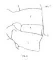
- FIG. 1is an anterior view of a targeted motion segment comprising lumbar vertebrae wherein a portion of a disc of the targeted motion segment is replaced with a bone graft.
- FIG. 2is a lateral view of the targeted motion segment of FIG. 1 .
- FIG. 3Ais a perspective view of an embodiment of an implant in accordance with the present invention for stabilizing the bone graft of FIG. 1 .
- FIG. 3Bis a partially exploded perspective view of the implant of FIG. 3A .
- FIG. 4Ais an anterior view of the implant of FIG. 3A .
- FIG. 4Bis an anterior view of a locking plate of the implant of FIG. 3A .
- FIG. 5Ais a lateral view of the implant of FIG. 3A .
- FIG. 5Bis a reverse lateral view of the locking plate of FIG. 3A showing a keel and a protuberance of the locking plate.
- FIG. 6is a perspective view of an alternative embodiment of an implant in accordance with the present invention having an anchoring plate with a recess for receiving a locking plate.
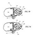
- FIG. 7Ais a perspective view of a still further embodiment of the implant in accordance with the present invention having a locking cam in substitution of a locking plate, the cam being arranged at a first position.
- FIG. 7Bis a perspective view of the implant of FIG. 7B wherein the locking cam in arranged at a second position.
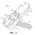
- FIG. 8Ais an anterior view of another embodiment of the implant in accordance with the present invention having a bore for receiving a locking screw in substitution of a locking plate.
- FIG. 8Bis a lateral view of a locking screw for use with the implant of FIG. 8A .
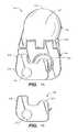
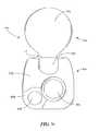
- FIGS. 9A and 9Bare anterior and posterior views of still another embodiment of an implant in accordance with the present invention.
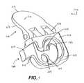
- FIG. 10is a partially exploded perspective view of the implant of FIGS. 9A and 9B .
- FIGS. 1A and 11Bare lateral views of the implant of FIGS. 9A and 9B illustrating a general range of motion of the implant.
- FIG. 12is a lateral view of still another embodiment of an implant in accordance with the present invention having a bone screw arrangement adapted to have a range of motion and anchoring plate cleats.
- FIG. 13is an anterior view of a targeted motion segment comprising lumbar vertebrae having a bone graft positioned in place of a portion of the disc and an implant arranged to resist expulsion of the bone graft.
- FIG. 14is a lateral view of the targeted motion segment of FIG. 13 .
- FIGS. 15A and 15Bdepict yet an alternative embodiment of the invention.
- FIGS. 16A and 16Bdepict an insertion tool of an embodiment of the invention.
- FIG. 17is a flow diagram of an embodiment of a method for resisting expulsion of a bone graft in accordance with the present invention.
- FIG. 1shows a simplified anterior view of a targeted motion segment 1 in the lumbar region of an exemplary spine.
- FIG. 2shows a simplified lateral view of the targeted motion segment 1 .
- the targeted motion segment 1need not comprise vertebrae of the lumbar region, but rather can comprise vertebrae of any motion segment along the spine, including vertebrae of the thoracic and cervical regions.
- an unhealthy (i.e., defective) disc 4is disposed between lumbar vertebrae 2 , 3 .
- An unhealthy disccan result from a number of different causes such as degenerative disc disease, isthmic, degenerative or postlaminectomy spondylolisthesis, instability caused by infection or tumors, fractures, scoliosis, deformity, or some other abnormality.
- abnormal and/or excessive motion at the motion segmentmay result in pain (e.g., from collapse of the foraminal space or herniation of the disc).
- One solution for alleviating pain associated with an unhealthy disccan include stabilizing the motion segment by restricting relative movement of the respective vertebrae. Movement can be restricted by fusing together the vertebrae between which the non-healthy disc is disposed. Fusion can be achieved using a number of different devices and techniques. Spinal fusion surgery is designed to stop the motion at a painful motion segment, which in turn should decrease pain generated at the motion segment. Spinal fusion surgery can involve adding bone graft to an area of the spine to provoke a biological response that causes the bone graft to grow between the two vertebrae to form substantially continuous rigid bone, thereby stopping the motion at that motion segment.
- spinal fusion surgery optionsincluding (but not limited to) anterior interbody fusion, a technique performed from the front and including removing the disc between the two vertebrae of the targeting motion segment and inserting bone into the space created between the two vertebrae and anterior/posterior spinal fusion, a technique performed from both the front and the back.
- Bone graftcan be taken from a patient's hip during the spinal fusion surgery, or harvested from cadaver bone. Alternatively, a synthetic bone graft substitute can be used in place of a bone graft. For example, bone morphogenic proteins are currently used for fusion procedures.
- the size of the bone graftcan vary at the discretion of the physician.
- the bone graftcan comprise a plug of material approximately conforming with a cavity formed within the disc, the bone graft can comprise a substitute for the disc and can be sized to substantially replace the entire disc, or the bone graft can have some other shape and size.
- the surgical technique appliedcan vary and/or influence a bone graft shape and size.
- the targeted motion segment 1 of FIGS. 1 and 2includes a bone graft 5 comprising a plug positioned within a cavity formed in the unhealthy disc 4 accessed by way of an anterior approach. Providing a point of insertion of the bone graft 5 can also provide a point of expulsion.
- a bone graft or plugit is to be understood that fusion devices plugs made of a metal such as titanium or a polymer such as polyetheretherketone (PEEK).
- PEEKpolyetheretherketone
- Such a fusion devicecan include a cage that can be packed with bone to facilitate the fusion of adjacent vertebrae positioned above and below the fusion device. Such fusion devices can be seen by way of example only in U.S. Pat. Nos.
- An implant in accordance with the present inventioncan comprise a buttress plate 100 positionable such that at least a portion of the buttress plate 100 resists expulsion of a bone graft disposed within a cavity such as shown in FIGS. 1 and 2 .
- the implantis a buttress plate 100 having a vertebral plate (also referred to herein as an anchoring plate) 120 and an intervertebral plate 110 extending from the anchoring plate 120 and connected to the anchoring plate 120 by way of a hinge 122 .
- the intervertebral plate 110as shown in FIG.
- the intervertebral plate 110can be saucer-shaped; however, as with all embodiments described herein, the intervertebral plate 110 alternatively have some other shape, such as square.
- the hinge 122allows the anchoring plate 120 to bend at a wide range of angles relative to the intervertebral plate 110 .
- the hinge 122is designed so that it restricts the motion of the intervertebral plate 110 to preferably remaining about parallel with the anchoring plate 120 as seen in FIG. 3A .
- Such restricted motioncan be accomplished by extending a flange from the anterior surface of the anchoring plate 120 so that the anterior surface 113 of the intervertebral plate 110 contacts the flange and thus restricts motion of the intervertebral plate 110 when the intervertebral plate 110 is about parallel with the anchoring plate as seen in FIG. 3A . Accordingly this restriction allows the buttress plate 100 to retain the fusion plug in place between the vertebrae as depicted in FIGS. 13 and 14 .
- the hinge 122however, allows the intervertebral plate 110 rotate clockwise in FIG. 3A and thus to approach the posterior surface of the anchoring plate 120 .
- Range of motioncan facilitate positioning and insertion of the intervertebral plate 110 into an incision within a patient, the anatomy of which can be highly variable among individuals. This characteristic also applies to embodiments described below, which have a hinge or which are otherwise enabled to bend by some equivalent structure or material property.
- the intervertebral plate 110can be curved or rounded at a distal end 112 ( FIG. 5A ).
- the intervertebral plate 110can include an anterior surface 115 having a shape generally conforming with a shape of the outer surface of the bone graft, although the shape need not be identical to that of the bone graft.
- the intervertebral plate 110can further include an anterior surface 113 having a shape approximating that of the bone graft and/or the disc replaced by the bone graft, so that interference, friction or irritation between the buttress plate 100 and tissues and structures in close proximity to and/or associated with the unhealthy disc.
- the surfaces 113 , 115 of the intervertebral plate 110can vary in shape and size; however, in a preferred embodiments, the surfaces 113 , 115 should be shaped (1) to distribute a force applied to the surface by movement of a bone graft across the surface, and (2) to minimize interference with other tissues and/or structures surrounding the intervertebral plate 110 .
- the anchoring plate 120when implanted in the spine, is positioned adjacent to one of the upper and lower vertebrae associated with the targeted motion segment.
- the anchoring plate 120has a generally square shape with rounded corners; however, in other embodiments (and with all embodiments herein described) the anchoring plate 120 can have any number of shapes so long as the anchoring plate 120 provides sufficient support for anchoring the implant 100 in position and so long as the anchoring plate 120 allows a desired range of motion for the intervertebral plate 110 during implantation.
- the anchoring plate 120has a bore 130 therethrough, the bore 130 being adapted to receive a bone screw 140 for securing the anchoring plate 120 to the corresponding vertebra, thereby anchoring the buttress plate 100 .
- a locking plate 124can be mated with the anchoring plate 120 to resist rotation of the anchoring plate 120 .
- a keel 128extends from the locking plate 124 and has a wedge shaped distal end adapted to pierce the vertebra with which the bone screw 140 is associated.
- the keel 128aligns with a groove 123 through an edge of the anchoring plate 120 to guide and align the keel 128 as the keel 128 cuts into the vertebra.
- the locking plate 124includes a protuberance 126 that is positioned at least partially within the bore 130 and in contact or near contact with a head 142 of the bone screw 140 .
- the locking plate 124further includes a bore 131 that can accept a machine screw (not shown) which passes through to an aligned bore 129 in the anchoring plate 120 to hold the locking plate 124 and the anchoring plate 120 together without rotational displacement relative to each other.
- the locking plate 124thus serves at least two functions: (1) maintaining the position of the bone screw 140 with the protuberance 126 so that the bone screw 140 does not back out; and (2) using the keel 128 to prevent rotation of the buttress plate 100 relative to the vertebra with which the implant buttress plate 100 is connected.
- other mechanismscan be employed to resist movement of the anchoring plate 120 relative to the vertebra.
- Implants in accordance with the present inventionare not intended to be limited to those embodiments described in detail herein, but rather are meant to apply to all such embodiments comprising anchoring plates moveably connected with intervertebral plates for resisting expulsion of a bone graft.
- FIG. 6illustrates an alternative embodiment of an implant in accordance with the present invention, wherein an anchoring plate 220 can include a recessed anterior surface 223 for receiving the locking plate 224 so that the locking plate 224 is flush with the exposed anterior surface 225 of the anchoring plate 220 when the protuberance 226 is urged against the bone screw 240 and the keel 228 of the locking plate 224 is inserted into the vertebra.
- some other structurecan be employed to resist movement of the seated bone screw within the first bore. Referring to the embodiments of FIGS.
- a cam 324can be rotatably associated with the anchoring plate 320 so that the first bore 330 can be selectably obstructed or unobstructed, thereby allowing a bone screw 340 to be received within the first bore 330 , or resisting movement of the bone screw 340 seated within the first bore 330 .
- the cam 324can have a shape such that at a first position the surface 328 of the cam is approximately flush with the first bore 330 , allowing a bone screw 340 to pass through the first bore 330 . Rotated to a second position ( FIG.
- a protruding portion 326 of the surface of the cam 324can extend across at least a portion of the first bore 330 , blocking the bone screw 340 seated within the first bore 330 and preventing the bone screw 340 from backing out of the first bore 330 .
- the cam 324can include features 331 (e.g., indentations) that can allow the cam to be grasped with a tool (not shown), and thus rotated to the desired position. As shown, the cam 324 is positioned within a slot of the anchoring plate 320 so that the cam 324 does not protrude undesirably from the surface of the anchoring plate 320 .
- FIGS. 3A-5Bis similar to embodiments shown in FIGS. 6-8B . Accordingly, the remaining elements on the 200 and 300 series of element numbers are preferably substantially similar to the described elements in the 100 series of element numbers, as set forth above. Thus, by way of example, elements 223 , 228 , 229 and 230 are similar, respective elements 123 , 128 , 129 and 130 .
- FIG. 8Ais an anterior view of a further embodiment of an implant in accordance with the present invention.
- the implantcomprises a buttress plate 400 including an intervertebral plate 410 that optionally includes a tapered or thinned distal end 412 .
- the intervertebral plate 410is pivotably connected with an anchoring plate 420 by a hinge 422 .
- the implant 400is substantially hour-glass shaped.
- the hinge 422is narrower than the intervertebral plate 410 , with the hinge 422 sitting at substantially an isthmus 417 between intervertebral plate 410 and the anchoring plate 420 .
- the curved edges, or fillets, about the hinge 422distribute more evenly load-bearing stress on the intervertebral plate 410 , and prevent stress concentrations about the edges.
- the intervertebral plate 410preferably includes an anterior surface 415 having a shape approximately conforming with a shape of the contact surface of the bone graft and/or the outer surface of the disc.
- the curvecan have a uniform thickness, or it can have a varied thickness.
- the lateral edges of the intervertebral plate 410are curved or rounded, for distribution of load-bearing stress.
- the hinge 422allows the implant 400 to pivot relative to the anchoring plate 420 .
- the buttress plate 400is mechanically prevented from pivoting away from the bone graft when the anchoring plate 420 is correctly connected with a vertebra.
- the buttress plate 400thus resists expulsion of a bone graft.
- the anchoring plate 420further includes a second bore 429 which is preferably arranged medially relative to the first bore 430 .
- the second bore 429is adapted to accept a locking screw 490 ( FIG. 8B ), which preferably includes a chisel point 491 .
- the locking screw 490is received by the second bore 429 and the chisel point 491 self-cuts a bore into the bone.
- the locking screw 490preferably is inserted through the second bore 429 and embedded into the bone, after the bone screw 440 is embedded into the bone through the first bore 430 .
- the position of the second bore 429i.e., medial to the first bore 430 , is more centrally located relative to the corresponding vertebra so that it embeds in stronger bone tissue than if the second bore 429 were located more laterally.
- the locking screw 490in combination with the bone screw 440 prevents rotational movement of the buttress plate 400 relative to the vertebra.
- a head 492 of the locking screw 490can overlap at least a portion of the head 442 of the bone screw 440 in the first bore 430 , coming into contact or near contact to prevent the bone screw 440 from backing out of the bone of the vertebra.
- Embodiments of the inventioncan be made without a hinge, as long as the connection between the intervertebral plate and the anchoring plate is flexible enough to allow the anchoring plate to be bent relative to the intervertebral plate in order to fit the anatomy of the patient.
- a still further embodiment of an implant in accordance with the present inventioncan comprise a buttress plate 500 including an intervertebral plate 510 connected with an anchoring plate 520 by a spheroidal joint arrangement 538 or otherwise shaped multiple direction articulation joint arrangement.
- the intervertebral plate 510has a saucer shape, but as described in further detail below (and as described in previous embodiments above), in other embodiments the intervertebral plate 510 can have some other shape so long as a desired obstruction is achieved.
- the intervertebral plate 510includes a handle-like structure necking at an isthmus 517 and terminating at a pivot end 526 .
- the pivot end 526is substantially spherical, ovoidal, or similarly rounded in shape.
- the anchoring plate 520has a generally square shape with rounded corners; however, in other embodiments the anchoring plate 520 can have any number of shapes so long as the anchoring plate 520 provides sufficient support for anchoring the implant 500 in position and so long as the anchoring plate 520 allows a desired range of motion for the intervertebral plate 510 during implantation.
- the anchoring plate 520includes a cavity 527 within which the pivot end 526 is held.
- the spheroidal joint arrangement 538comprises the pivot end 526 and the cavity 527 and as described below allows the intervertebral plate 510 to tilt and swivel as desired relative to the anchoring plate 520 .
- FIG. 9Ais an anterior view showing an anterior face 532 of the anchoring plate 520
- FIG. 9Bis a posterior view showing a posterior face 534 of the anchoring plate 520
- the anchoring plate 520includes a posterior notch 524 (see FIG. 10 ) or other indentation formed along the edge of the posterior face 534 and an anterior notch 522 or other indentation formed along the anterior face 532 .
- the posterior and anterior notches 524 , 522are generally aligned with one another along the edge of the anchoring plate 520 and are associated with the cavity 527 .
- the notches 522 , 524confine movement of the intervertebral plate 510 in the anterior and posterior directions relative to the anchoring plate 520 , allowing the intervertebral plate 510 to tilt at varying degrees of angle in an anterior and posterior direction.
- the anterior notch 524can have a wider width than the posterior notch 522 and is sized to provide the pivot end 526 of the intervertebral plate 510 with access to the cavity 527 so that the pivot end 526 can be inserted into the cavity 527 .
- a plug 528can be mated with the anchoring plate 520 to lock the pivot end 526 in place within the cavity 527 and to further limit freedom of movement of the intervertebral plate 510 , particularly limiting tilting of the intervertebral plate 510 in an anterior direction that is in a direction away from a fusion plug in order to assist in retaining the fusion plug in place between vertebrae.
- the plug 528can be press fit to the anterior notch 522 and further welded or otherwise fixedly fastened with the anchoring plate 520 .
- the anchoring plate 520has a first bore 530 therethrough.
- the first bore 530can accept a bone screw 540 to secure the anchoring plate 520 preferably to one of the vertebrae, thereby anchoring the implant 500 .
- the bone screw 540preferably has a head 542 that can accept a tool chosen for the surgical procedure whether a wrench, screwdriver, or other tool.
- the anchoring plate 520further has a second bore 529 which is preferably positioned medially, relative to the first bore 530 .
- the second bore 529 through the anchoring plate 520is adapted to accept a locking screw 590 having a chisel point 591 .
- the locking screw 590is received by the second bore 529 and the chisel point 591 self-cuts into the bone.
- the locking screw 590is preferably inserted through the second bore 529 and embedded in the bone after the bone screw 540 is embedded in the bone through the first bore 530 .
- the locking screw 590in combination with the bone screw 540 , prevents rotational displacement of the anchoring plate 520 relative to the vertebra.
- the second bore 529is preferably positioned so that a head 592 of the locking screw 590 overlaps at least a portion of the head 542 of the bone screw 540 .
- the head 592 of the locking screw 590comes in contact or near contact over the head 542 of the bone screw 540 , blocking movement of the head 542 and preventing the first bone screw 540 from backing out of the bone of the vertebra and the first bore 530 .
- the anterior face 532 of the anchoring plate 520can optionally include a recessed portion 539 and/or the second bore 529 can be countersunk, so that the locking screw 590 does not protrude farther from the anterior face 532 than desired.
- the spheroidal joint arrangement 538includes a spherical pivot end 526 and a cavity 527 having a shape approximately conforming to the spherical pivot end 526 so that the spheroidal joint arrangement 538 is a ball-in-socket arrangement.
- the ball-in-socket arrangement 538allows the intervertebral plate 510 to move relative to the anchoring plate 520 .
- the intervertebral plate 510can tilt in a posterior direction (to position 1 , for example) and can tilt in an anterior direction (to position 2 , for example).
- the isthmus 517moves within the posterior notch 524 so that the intervertebral plate 510 can continue tilting.
- the isthmus 517contacts the plug 528 , limiting the amount of tilt of the intervertebral plate 510 in a anterior direction.
- the plug 528acts like a flange extending from the anchoring plate 520 in order to limit the motion of the intervertebral plate 510 relative to the anchoring plate 520 .
- the intervertebral plate 510can be about parallel to the anchoring plate 520 to for example retain a fusion plug in place and can rotate counterclockwise in FIG. 11A toward the anchoring plate 520 .
- the ball-and-socket arrangementallows the intervertebral plate 510 to swivel (to position 3 , for example) relative to the anchoring plate 520 , potentially providing a physician more freedom to manipulate the implant 500 .
- the amount of swiveling accommodateddepends on the geometries of the components. For example, where the isthmus 517 is sufficiently narrow and long in length, a greater degree of swiveling in combination with tilt can be achieved, or for example where the plug 528 extends over a portion of the intervertebral plate 510 , as shown in FIGS.
- the amount of tilt possible in the anterior directioncan be limited, thereby resisting expulsion of the bone graft.
- the freedom of movement of the intervertebral plate 510 relative to the anchoring plate 520is limited substantially or wholly by the geometries of the components, and therefore can be substantially altered to achieve a desired range of movement.
- the ball-and-socket arrangementneed not include a ball that extends from the intervertebral plate and a socket that is formed in the anchoring plate.
- the ball of such a jointcan extend from a locking or anchoring plate and the socket can be included in the intervertebral plate.
- the preferred embodimenthas been described as a ball-and-socket arrangement; other arrangements can be employed with varied results. It should not be inferred that embodiments in accordance with the present invention need include a spheroidal shaped end mated with a rounded cavity.
- the scope of the present inventionis not intended to be limited to ball-and-socket arrangements, but rather is intended to encompass all such arrangements that provide a plurality of degrees of freedom of movement and substitutability of components.
- the implant 600can further optionally include plate cleats 688 extending from a surface of the anchoring plate 620 substantially contacting the corresponding vertebra.
- the plate cleats 688can help anchor the anchoring plate 620 in position either to assist in resisting shifting as a bone screw 640 is associated with the vertebra, or as an adjunct to the bone screw 640 .
- Surface roughening caused by the plate cleats 688can further promote bone growth near and/or integrally with the anchoring plate 620 .
- there are four plate cleats (one behind the other) 688each plate cleat 688 having a conical structure.
- the plate cleats 688can vary in size, number and shape.
- the plate cleats 688can have a saw-tooth shape, a pyramid shape, a curved shape, etc.
- retainer 624can be used to keep the bone screw 640 from backing out.
- Retainer 624can be secured to the anchoring plate 620 with a screw.
- FIG. 13is a simplified anterior view of the targeted motion segment 1 of FIGS. 1 and 2 including an embodiment of an implant in accordance with the present invention fixedly associated with the upper vertebra of the targeted motion segment 1 .
- FIG. 14is a simplified lateral view of the targeted motion and implant of FIG. 13 .
- the targeted motion segment 1includes a bone graft 5 comprising a plug positioned within a cavity formed in the unhealthy disc 4 accessed by way of an anterior approach.
- the bone graft 5is prevented from being expelled from the cavity as a result of compressive forces applied to the spine or other forces by the intervertebral plate 410 , which as seen particularly in FIG. 14 comes in contact or near contact with the bone graft 5 .
- the anchoring plate 410is fixed to the upper vertebra 2 so that the intervertebral plate 410 extends over the bone graft 5 , obstructing movement of the bone graft 5 in an anterior direction. If desired the anchoring plate 420 can instead be affixed to the lower vertebra 3 .
- FIG. 17is a flow chart of an embodiment of a method in accordance with the present invention for implanting an implant as described in FIGS. 2A through 8B .
- Embodiments of the present inventioncan be inserted in the following manner, however, only elements of the embodiment 100 will be set forth herein.
- the intervertebral plate 110is positioned to obstruct expulsion of the bone graft (Step 104 ).
- a borecan be drilled in the bone to accommodate the bone screw 140 (Step 106 ).
- the screw 140can be self-tapping. The bone screw 140 is then threaded and/or inserted through the bore 130 and secured to the bone of the vertebrae, holding the intervertebral plate 110 in place (Step 108 ).
- a locking plate 124can then be positioned over the anchoring plate 120 to lock the bone screw 140 in place and to lock the position of the intervertebral plate 110 and the anchoring plate 120 in place (Step 110 ). So positioned, a protuberance 126 is disposed at least partially through the bore 130 and in contact or near contact with a head 142 of the bone screw 140 to keep the bone screw 140 from backing out.
- a keel 128 of the locking plate 124having a sharp chisel-shaped end, preferably can self-cut a groove in the bone so that the keel 128 is locked into the bone. In some embodiments, the keel 128 is aligned by and received in a groove 131 of the anchoring plate 120 .
- a groovecan be pre-cut in the bone to receive the keel 128 .
- a bore 129 of the locking plate 124aligns with a threaded bore 131 of the anchoring plate 120 and a machine screw can be inserted to fix the locking plate 124 to the anchoring plate 120 .
- Lockingprevents the anchoring plate 120 and the intervertebral plate 110 from rotating relative to each other and resists movement relative to the vertebrae. Further, the locking plate 124 prevents the bone screw 140 from backing out from the vertebra.
- FIG. 15Adepicts a posterior view of another embodiment 700 of the implant of the invention.
- the buttress plate embodiment 700as well as all of the embodiments herein, can benefit from some or all of the features and advantages with regard to the other embodiments described herein.
- the buttress plate 700has an intervertebral plate 710 that can have a tapered or thinned distal end 712 .
- the intervertebral plate 710further can be curved so that a superior surface 713 of the intervertebral plate 710 is convex, and an inferior surface 715 is concave.
- the inferior surface 715is substantially flat whereby the superior surface 713 is convex ( FIG. 15B ). As shown in FIG.
- the convex superior surface 713tapers downward at an increased angle toward the inferior surface 715 at the distal end 712 .
- This contour of the superior surface 713aids in smooth insertion of the intervertebral plate 710 into the facet joint.
- the intervertebral plate 710also can be made of a flexible, biocompatible material, such as PEEK, to maintain joint mobility and flexibility.
- the intervertebral plate 710is connected flexibly with the anchoring plate 720 , preferably with a hinge 722 .
- the hinge 722allows the intervertebral plate 710 and the anchoring plate 720 of the buttress plate 700 to bend with respect to one another between an extended position and a bent or folded position as discussed above.
- a second bone screwcan be inserted through a second bore 729 in the anchoring plate 720 , whereby the second bone screw would be embedded into the bone of the vertebral body. Details of the first and second bores are discussed above.
- the anchoring plate 720is made of a biocompatible flexible material, preferably titanium or any other biocompatible flexible material as described herein, for example PEEK, that will support the use of bone screws and other hardware, as described below.
- the anchoring plate 720bends downward about the hinge 722 over a wide range of angles relative to the intervertebral plate 710 .
- any other type of interface between the intervertebral plate 710 and the anchoring plate 720is contemplated (e.g. ball and socket joint). This flexibility facilitates positioning and insertion of the intervertebral plate 710 .
- FIG. 15Bdepicts a side view of the buttress plate and anchoring plate in accordance with one embodiment.
- the intervertebral plate 710includes an hyper-extension tab 722 in one embodiment.
- the hyper-extension tab 722prevents the intervertebral plate 710 from moving relative to the anchoring plate 720 in a direction beyond the extended position which is shown in FIGS. 15A and 15B .
- the anchoring plate 720preferably includes a recess 711 at the interface between the anchoring plate 720 and the intervertebral plate 710 which seats the tab 722 in the extended position which is shown in FIG. 15A .
- the tab 722When the intervertebral plate 710 is bent at an angle, the tab 722 is not in contact with the recess 711 . However, the tab 722 comes into contact with the recess 711 when in the extended position, as shown in FIG. 15A . Thus, the tab 722 , when seated in the recess 711 , prevents the intervertebral plate 710 from moving beyond the extended position depicted.
- the anchoring plate 720preferably includes a third bore 702 located near a rear edge, whereby the third bore 752 preferably receives an engaging rod 816 ( FIG. 16B ) of an implantation tool 800 described below.
- the third bore 702preferably extends through the superior and inferior surfaces of the anchoring plate, although not necessarily.
- the third bore 702is circular in shape, any other shape is contemplated which engages a correspondingly shaped engaging rod 816 ( FIG. 16B ).
- the rear edge 704 of the anchoring plate 720can be engaged by the engagement head 806 ( FIG. 16B ) of the implantation tool 800 as described below.
- the anchoring plate 720preferably includes one or more winged protrusions, such as tabs, winglets or ears, 708 which protrude from the side edges of the anchoring plate 720 .
- FIG. 15Aillustrates the buttress plate 700 having two winged protrusions 708 .
- the protrusions 708serve as guides to successfully couple the buttress plate 700 to the implantation tool 800 .
- the protrusionsact as an engaging mechanism which secures the buttress plate 700 to the tool 800 .
- the winged protrusions 708are preferred and the buttress plate 700 can be configured in any other appropriate design to ensure that the buttress plate 700 is able to be effectively guided and secured to the implantation tool 800 .
- FIG. 16Adepicts an implantation tool in accordance with one embodiment of the present invention.
- the tool 800preferably includes a handle 802 having a proximal end and a distal end.
- the tool 800includes an actuating switch 808 as well as a shaft 804 extending from the distal end of the handle 802 .
- the shaft 804preferably extends axially with the handle 802 , although the shaft 804 may be at an angle with respect to the handle 802 .
- Extending from the shaft 804is an engagement head 806 , whereby the engagement head is preferably oriented at an angle with respect to the shaft 804 and/or the handle 802 .
- the angle of the head 806 relative to the shaft 804aids the surgeon in the process of implanting the buttress plate 700 in the spine.
- the headis at an angle between 45 and 90 degrees relative to the handle 804 .
- other anglesare contemplated.
- the engagement head 806preferably has a forked configuration and includes a pair of side walls 810 , an engagement seat 812 as well as a receiving space 818 which is defined as the area between the side walls 810 and the seat 812 .
- the engagement head 806preferably includes a retractable engaging rod 816 which extends partially into the receiving space 818 .
- the side walls 810each have an inner side which includes a slot 812 whereby the slots 812 face the receiving space 818 .
- the slots 812are dimensioned to slidably receive the wing protrusions 708 of the lateral mass plate 720 as well as secure the anchoring plate 720 to the engagement head 806 .
- the engagement seat 812receives the rear edge 704 of the anchoring plate 720 .
- the engagement head 806preferably includes the engaging rod 816 , as shown in FIG. 16B .
- the engaging rod 816is dimensioned to fit within the third bore 702 in the anchoring plate 720 .
- the engaging rod 816is coupled the switch 808 on the handle 802 , whereby actuation of the switch 808 causes the engaging rod 816 to retract.
- the engaging rod 816disengages the third bore 702 and allows the buttress plate 700 to be disengaged from the engagement head 806 .
- the tool 800includes a spring or other urging means to urge the engaging rod 816 to the extended position, as shown in FIG. 16B .
- the engaging rod 816is freely moveable between the extended and retracted positions without a biasing force applied thereto.
- the engaging rod 816is shown as being a circular cylinder in FIGS. 16A and 16B .
- the engaging rod 816can have any other shape which conforms to the shape of the third bore 702 in the anchoring plate 720 .
- the engagement head 806does not include an engaging rod 816 but some other mechanism to secure the buttress plate 700 to the tool 800 .
- the slots 812 in the side walls 810can be used to retain the buttress plate 700 in the head 806 without the use of an engaging mechanism.
- the implant 700is oriented to be right side up such that the rear surface 704 of the buttress plate 700 will conform and mate with the engagement seat 814 .
- the buttress plate 700is aligned with the forked portion of the engagement head 806 , whereby the winged protrusions 708 of the buttress plate 700 are inserted into the slot openings 812 .
- the anchoring plate 720is guided into engagement by the slots 812 until the rear edge 704 mates with the engagement seat 814 .
- the engaging rod 816is then inserted into the third bore 702 , thereby securing the anchoring plate 720 to the engagement head 806 .
- the usermanually actuates the switch 808 to retract the engaging rod 816 to allow the anchoring plate 720 to be inserted completely in the receiving space.
- the switch 808is then manually released when the bore 702 and engaging rod 816 are aligned such that the engaging rod 816 then extends and engages the third bore 702 .
- contact between the superior surface of the anchoring plate 720 and the engaging rod 816causes the engaging rod 816 to slightly retract while the anchoring plate 720 is moved into the engagement seat 814 .
- the third bore 702preferably registers with the engaging rod 816 , whereby the urging force causes the engaging rod 816 to automatically engage the third bore 702 .
- the intervertebral plate 710is positioned over the bone plug or fusion cage as described in detail above.
- the surgeonpreferably actuates the switch 808 to disengage the engaging rod 816 from the third bore 702 .
- the surgeonthen draws the tool 800 away from the spine, whereby the anchoring plate 720 slides out of the received area and is guided by the slots 812 .
- the anchoring plate 720is then anchored into the vertebral body as discussed above.
- the implant, and components of the implantcan be fabricated from medical grade metals such as titanium, stainless steel, cobalt chrome, and alloys thereof, or other suitable implant material having similar high strength and biocompatible properties.
- the implantcan be at least partially fabricated from a shape memory metal, for example Nitinol, which is a combination of titanium and nickel. Such materials are typically radiopaque, and appear during x-ray imaging, and other types of imaging.
- Implants in accordance with the present invention, and/or portions thereofcan also be fabricated from somewhat flexible and/or deflectable material.
- the implant and/or portions thereofcan be fabricated in whole or in part from medical grade biocompatible polymers, copolymers, blends, and composites of polymers.
- a copolymeris a polymer derived from more than one species of monomer.
- a polymer compositeis a heterogeneous combination of two or more materials, wherein the constituents are not miscible, and therefore exhibit an interface between one another.
- a polymer blendis a macroscopically homogeneous mixture of two or more different species of polymer.
- Many polymers, copolymers, blends, and composites of polymersare radiolucent and do not appear during x-ray or other types of imaging. Implants comprising such materials can provide a physician with a less obstructed view of the spine under imaging, than with an implant comprising radiopaque materials entirely. However, the implant need not comprise any radiolucent materials.
- PEEKpolyetheretherketone
- PEKKpolyetherketoneketone
- PEEKis proven as a durable material for implants, and meets the criterion of biocompatibility.
- Medical grade PEEKis available from Victrex Corporation of Lancashire, Great Britain under the product name PEEK-OPTIMA.
- Medical grade PEKKis available from Oxford Performance Materials under the name OXPEKK, and also from CoorsTek under the name BioPEKK. These medical grade materials are also available as reinforced polymer resins, such reinforced resins displaying even greater material strength.
- the implantcan be fabricated from PEEK 450G, which is an unfilled PEEK approved for medical implantation available from Victrex.
- PEEK 450Ghas the following approximate properties:
- the implant and/or portions thereofcan be formed by extrusion, injection, compression molding and/or machining techniques.
- Fillerscan be added to a polymer, copolymer, polymer blend, or polymer composite to reinforce a polymeric material. Fillers are added to modify properties such as mechanical, optical, and thermal properties. For example, carbon fibers can be added to reinforce polymers mechanically to enhance strength for certain uses, such as for load bearing devices.
- other grades of PEEKare available and contemplated for use in implants in accordance with the present invention, such as 30% glass-filled or 30% carbon-filled grades, provided such materials are cleared for use in implantable devices by the FDA, or other regulatory body. Glass-filled PEEK reduces the expansion rate and increases the flexural modulus of PEEK relative to unfilled PEEK.
- Carbon-filled PEEKis known to have enhanced compressive strength and stiffness, and a lower expansion rate relative to unfilled PEEK. Carbon-filled PEEK also offers wear resistance and load carrying capability.
- the implantcan be comprised of polyetherketoneketone (PEKK).
- PEKKpolyetherketoneketone
- Other material that can be usedinclude polyetherketone (PEK), polyetherketoneetherketoneketone (PEKEKK), polyetheretherketoneketone (PEEKK), and generally a polyaryletheretherketone.
- PEKpolyetherketone
- PEKEKKpolyetherketoneetherketoneketone
- PEEKKpolyetheretherketoneketone
- other polyketonescan be used as well as other thermoplastics.
Landscapes
- Health & Medical Sciences (AREA)
- Orthopedic Medicine & Surgery (AREA)
- Engineering & Computer Science (AREA)
- Biomedical Technology (AREA)
- Life Sciences & Earth Sciences (AREA)
- Heart & Thoracic Surgery (AREA)
- Veterinary Medicine (AREA)
- Public Health (AREA)
- General Health & Medical Sciences (AREA)
- Neurology (AREA)
- Animal Behavior & Ethology (AREA)
- Transplantation (AREA)
- Surgery (AREA)
- Vascular Medicine (AREA)
- Oral & Maxillofacial Surgery (AREA)
- Cardiology (AREA)
- Nuclear Medicine, Radiotherapy & Molecular Imaging (AREA)
- Medical Informatics (AREA)
- Molecular Biology (AREA)
- Physical Education & Sports Medicine (AREA)
- Prostheses (AREA)
Abstract
Description
| Property | Value | ||
| Density | 1.3 | g/cc | ||
| Rockwell M | 99 | |||
| 126 | ||||
| Tensile Strength | 97 | MPa | ||
| Modulus of Elasticity | 3.5 | GPa | ||
| Flexural Modulus | 4.1 | GPa | ||
PEEK 450G has appropriate physical and mechanical properties and is suitable for carrying and spreading a physical load between the adjacent spinous processes. The implant and/or portions thereof can be formed by extrusion, injection, compression molding and/or machining techniques.
Claims (15)
Priority Applications (1)
| Application Number | Priority Date | Filing Date | Title |
|---|---|---|---|
| US11/304,202US8066749B2 (en) | 2004-12-13 | 2005-12-14 | Implant for stabilizing a bone graft during spinal fusion |
Applications Claiming Priority (15)
| Application Number | Priority Date | Filing Date | Title |
|---|---|---|---|
| US63545304P | 2004-12-13 | 2004-12-13 | |
| US11/053,624US7601170B2 (en) | 2004-12-13 | 2005-02-08 | Inter-cervical facet implant and method |
| US11/053,399US7591851B2 (en) | 2004-12-13 | 2005-02-08 | Inter-cervical facet implant and method |
| US11/053,346US20060149289A1 (en) | 2004-12-13 | 2005-02-08 | Inter-cervical facet implant and method |
| US11/053,735US7776090B2 (en) | 2004-12-13 | 2005-02-08 | Inter-cervical facet implant and method |
| US11/093,557US7763050B2 (en) | 2004-12-13 | 2005-03-30 | Inter-cervical facet implant with locking screw and method |
| US11/093,689US8100944B2 (en) | 2004-12-13 | 2005-03-30 | Inter-cervical facet implant and method for preserving the tissues surrounding the facet joint |
| US66805305P | 2005-04-04 | 2005-04-04 | |
| US67937705P | 2005-05-10 | 2005-05-10 | |
| US67936105P | 2005-05-10 | 2005-05-10 | |
| US67936305P | 2005-05-10 | 2005-05-10 | |
| US68776505P | 2005-06-06 | 2005-06-06 | |
| US71736905P | 2005-09-15 | 2005-09-15 | |
| PCT/US2005/044979WO2006065774A1 (en) | 2004-12-13 | 2005-12-13 | Inter-facet implant |
| US11/304,202US8066749B2 (en) | 2004-12-13 | 2005-12-14 | Implant for stabilizing a bone graft during spinal fusion |
Related Parent Applications (7)
| Application Number | Title | Priority Date | Filing Date |
|---|---|---|---|
| US11/053,399Continuation-In-PartUS7591851B2 (en) | 2004-12-13 | 2005-02-08 | Inter-cervical facet implant and method |
| US11/053,624Continuation-In-PartUS7601170B2 (en) | 2004-12-13 | 2005-02-08 | Inter-cervical facet implant and method |
| US11/053,735Continuation-In-PartUS7776090B2 (en) | 2004-12-13 | 2005-02-08 | Inter-cervical facet implant and method |
| US11/053,346Continuation-In-PartUS20060149289A1 (en) | 2004-12-13 | 2005-02-08 | Inter-cervical facet implant and method |
| US11/093,689Continuation-In-PartUS8100944B2 (en) | 2004-12-13 | 2005-03-30 | Inter-cervical facet implant and method for preserving the tissues surrounding the facet joint |
| US11/093,557Continuation-In-PartUS7763050B2 (en) | 2004-12-13 | 2005-03-30 | Inter-cervical facet implant with locking screw and method |
| PCT/US2005/044979Continuation-In-PartWO2006065774A1 (en) | 2004-12-13 | 2005-12-13 | Inter-facet implant |
Publications (2)
| Publication Number | Publication Date |
|---|---|
| US20060276897A1 US20060276897A1 (en) | 2006-12-07 |
| US8066749B2true US8066749B2 (en) | 2011-11-29 |
Family
ID=46062822
Family Applications (1)
| Application Number | Title | Priority Date | Filing Date |
|---|---|---|---|
| US11/304,202Expired - Fee RelatedUS8066749B2 (en) | 2004-12-13 | 2005-12-14 | Implant for stabilizing a bone graft during spinal fusion |
Country Status (1)
| Country | Link |
|---|---|
| US (1) | US8066749B2 (en) |
Cited By (38)
| Publication number | Priority date | Publication date | Assignee | Title |
|---|---|---|---|---|
| US8257439B2 (en) | 2004-12-22 | 2012-09-04 | Ldr Medical | Intervertebral disc prosthesis |
| US8267999B2 (en) | 2002-11-05 | 2012-09-18 | Ldr Medical | Intervertebral disc prosthesis |
| US8343219B2 (en) | 2007-06-08 | 2013-01-01 | Ldr Medical | Intersomatic cage, intervertebral prosthesis, anchoring device and implantation instruments |
| US8465546B2 (en) | 2007-02-16 | 2013-06-18 | Ldr Medical | Intervertebral disc prosthesis insertion assemblies |
| US8771284B2 (en) | 2005-11-30 | 2014-07-08 | Ldr Medical | Intervertebral disc prosthesis and instrumentation for insertion of the prosthesis between the vertebrae |
| US8858635B2 (en) | 2004-02-04 | 2014-10-14 | Ldr Medical | Intervertebral disc prosthesis |
| US8864828B2 (en) | 2004-10-20 | 2014-10-21 | Vertiflex, Inc. | Interspinous spacer |
| US8900271B2 (en) | 2004-10-20 | 2014-12-02 | The Board Of Trustees Of The Leland Stanford Junior University | Systems and methods for posterior dynamic stabilization of the spine |
| US8974532B2 (en) | 2004-04-28 | 2015-03-10 | Ldr Medical | Intervertebral disc prosthesis |
| US8979932B2 (en) | 2005-09-23 | 2015-03-17 | Ldr Medical | Intervertebral disc prosthesis |
| US9039742B2 (en) | 2004-10-20 | 2015-05-26 | The Board Of Trustees Of The Leland Stanford Junior University | Systems and methods for posterior dynamic stabilization of the spine |
| US9039774B2 (en) | 2012-02-24 | 2015-05-26 | Ldr Medical | Anchoring device and system for an intervertebral implant, intervertebral implant and implantation instrument |
| US9044337B2 (en) | 2009-12-31 | 2015-06-02 | Ldr Medical | Anchoring device and system for an intervertebral implant, intervertebral implant and implantation instrument |
| US9078765B2 (en) | 2001-07-13 | 2015-07-14 | Ldr Medical | Vertebral cage device with modular fixation |
| US9119680B2 (en) | 2004-10-20 | 2015-09-01 | Vertiflex, Inc. | Interspinous spacer |
| US9155570B2 (en) | 2004-10-20 | 2015-10-13 | Vertiflex, Inc. | Interspinous spacer |
| US9333095B2 (en) | 2001-05-04 | 2016-05-10 | Ldr Medical | Intervertebral disc prosthesis, surgical methods, and fitting tools |
| US9463091B2 (en) | 2009-09-17 | 2016-10-11 | Ldr Medical | Intervertebral implant having extendable bone fixation members |
| US9675389B2 (en) | 2009-12-07 | 2017-06-13 | Samy Abdou | Devices and methods for minimally invasive spinal stabilization and instrumentation |
| US9713535B2 (en) | 2006-02-15 | 2017-07-25 | Ldr Medical | Transforaminal intersomatic cage for an intervertebral fusion graft and an instrument for implanting the cage |
| US9839451B2 (en) | 2016-03-29 | 2017-12-12 | Christopher D. Sturm | Facet joint replacement device and methods of use |
| US9877842B2 (en) | 2014-01-30 | 2018-01-30 | Ldr Medical | Anchoring device for a spinal implant, spinal implant and implantation instrumentation |
| US9937050B2 (en) | 2013-05-16 | 2018-04-10 | Ldr Medical | Vertebral implant, vertebral fastening device of the implant and implant instrumentation |
| US10478310B2 (en) | 2014-05-06 | 2019-11-19 | Ldr Medical, S.A.S. | Vertebral implant, device for vertebral attachment of the implant and instrumentation for implantation thereof |
| US10548740B1 (en) | 2016-10-25 | 2020-02-04 | Samy Abdou | Devices and methods for vertebral bone realignment |
| US10575961B1 (en) | 2011-09-23 | 2020-03-03 | Samy Abdou | Spinal fixation devices and methods of use |
| US10603185B2 (en) | 2004-02-04 | 2020-03-31 | Ldr Medical | Intervertebral disc prosthesis |
| US10695105B2 (en) | 2012-08-28 | 2020-06-30 | Samy Abdou | Spinal fixation devices and methods of use |
| US10857003B1 (en) | 2015-10-14 | 2020-12-08 | Samy Abdou | Devices and methods for vertebral stabilization |
| US10918498B2 (en) | 2004-11-24 | 2021-02-16 | Samy Abdou | Devices and methods for inter-vertebral orthopedic device placement |
| US10973648B1 (en) | 2016-10-25 | 2021-04-13 | Samy Abdou | Devices and methods for vertebral bone realignment |
| US11006982B2 (en) | 2012-02-22 | 2021-05-18 | Samy Abdou | Spinous process fixation devices and methods of use |
| US11123117B1 (en)* | 2011-11-01 | 2021-09-21 | Nuvasive, Inc. | Surgical fixation system and related methods |
| US11173040B2 (en) | 2012-10-22 | 2021-11-16 | Cogent Spine, LLC | Devices and methods for spinal stabilization and instrumentation |
| US11179248B2 (en) | 2018-10-02 | 2021-11-23 | Samy Abdou | Devices and methods for spinal implantation |
| WO2022181977A1 (en)* | 2021-02-26 | 2022-09-01 | 경북대학교 산학협력단 | Spine fixing device |
| KR20220122435A (en)* | 2021-02-26 | 2022-09-02 | 경북대학교 산학협력단 | spinal fixation device |
| US12408959B2 (en) | 2022-07-13 | 2025-09-09 | Globus Medical, Inc. | Plate inserter system and method |
Families Citing this family (123)
| Publication number | Priority date | Publication date | Assignee | Title |
|---|---|---|---|---|
| AU2004212942A1 (en) | 2003-02-14 | 2004-09-02 | Depuy Spine, Inc. | In-situ formed intervertebral fusion device |
| US8945183B2 (en) | 2004-10-20 | 2015-02-03 | Vertiflex, Inc. | Interspinous process spacer instrument system with deployment indicator |
| US8123782B2 (en) | 2004-10-20 | 2012-02-28 | Vertiflex, Inc. | Interspinous spacer |
| US8277488B2 (en) | 2004-10-20 | 2012-10-02 | Vertiflex, Inc. | Interspinous spacer |
| US8025680B2 (en) | 2004-10-20 | 2011-09-27 | Exactech, Inc. | Systems and methods for posterior dynamic stabilization of the spine |
| US8267969B2 (en) | 2004-10-20 | 2012-09-18 | Exactech, Inc. | Screw systems and methods for use in stabilization of bone structures |
| US9023084B2 (en) | 2004-10-20 | 2015-05-05 | The Board Of Trustees Of The Leland Stanford Junior University | Systems and methods for stabilizing the motion or adjusting the position of the spine |
| US7935134B2 (en) | 2004-10-20 | 2011-05-03 | Exactech, Inc. | Systems and methods for stabilization of bone structures |
| US8317864B2 (en) | 2004-10-20 | 2012-11-27 | The Board Of Trustees Of The Leland Stanford Junior University | Systems and methods for posterior dynamic stabilization of the spine |
| US8409282B2 (en) | 2004-10-20 | 2013-04-02 | Vertiflex, Inc. | Systems and methods for posterior dynamic stabilization of the spine |
| US8425559B2 (en) | 2004-10-20 | 2013-04-23 | Vertiflex, Inc. | Systems and methods for posterior dynamic stabilization of the spine |
| US8012207B2 (en) | 2004-10-20 | 2011-09-06 | Vertiflex, Inc. | Systems and methods for posterior dynamic stabilization of the spine |
| US8226690B2 (en) | 2005-07-22 | 2012-07-24 | The Board Of Trustees Of The Leland Stanford Junior University | Systems and methods for stabilization of bone structures |
| US8128662B2 (en) | 2004-10-20 | 2012-03-06 | Vertiflex, Inc. | Minimally invasive tooling for delivery of interspinous spacer |
| US8162985B2 (en) | 2004-10-20 | 2012-04-24 | The Board Of Trustees Of The Leland Stanford Junior University | Systems and methods for posterior dynamic stabilization of the spine |
| US8613747B2 (en) | 2004-10-20 | 2013-12-24 | Vertiflex, Inc. | Spacer insertion instrument |
| US7763074B2 (en) | 2004-10-20 | 2010-07-27 | The Board Of Trustees Of The Leland Stanford Junior University | Systems and methods for posterior dynamic stabilization of the spine |
| US9161783B2 (en) | 2004-10-20 | 2015-10-20 | Vertiflex, Inc. | Interspinous spacer |
| US8123807B2 (en) | 2004-10-20 | 2012-02-28 | Vertiflex, Inc. | Systems and methods for posterior dynamic stabilization of the spine |
| EP2219538B1 (en) | 2004-12-06 | 2022-07-06 | Vertiflex, Inc. | Spacer insertion instrument |
| GB0505505D0 (en)* | 2005-03-17 | 2005-04-27 | Dall Desmond Meiring | Configurable bone fixation system |
| US8523865B2 (en) | 2005-07-22 | 2013-09-03 | Exactech, Inc. | Tissue splitter |
| US8366773B2 (en) | 2005-08-16 | 2013-02-05 | Benvenue Medical, Inc. | Apparatus and method for treating bone |
| WO2008103781A2 (en)* | 2007-02-21 | 2008-08-28 | Benvenue Medical, Inc. | Devices for treating the spine |
| AU2006279558B2 (en) | 2005-08-16 | 2012-05-17 | Izi Medical Products, Llc | Spinal tissue distraction devices |
| US20080058808A1 (en) | 2006-06-14 | 2008-03-06 | Spartek Medical, Inc. | Implant system and method to treat degenerative disorders of the spine |
| US8845726B2 (en) | 2006-10-18 | 2014-09-30 | Vertiflex, Inc. | Dilator |
| US8096996B2 (en) | 2007-03-20 | 2012-01-17 | Exactech, Inc. | Rod reducer |
| WO2008070863A2 (en) | 2006-12-07 | 2008-06-12 | Interventional Spine, Inc. | Intervertebral implant |
| US20080161929A1 (en) | 2006-12-29 | 2008-07-03 | Mccormack Bruce | Cervical distraction device |
| WO2008102174A2 (en)* | 2007-02-21 | 2008-08-28 | Surgicraft Limited | Orthopaedic implants and prostheses |
| EP2124778B1 (en) | 2007-02-21 | 2019-09-25 | Benvenue Medical, Inc. | Devices for treating the spine |
| AU2008241447B2 (en) | 2007-04-16 | 2014-03-27 | Vertiflex, Inc. | Interspinous spacer |
| US8048128B2 (en) | 2007-06-05 | 2011-11-01 | Spartek Medical, Inc. | Revision system and method for a dynamic stabilization and motion preservation spinal implantation system and method |
| US8109970B2 (en) | 2007-06-05 | 2012-02-07 | Spartek Medical, Inc. | Deflection rod system with a deflection contouring shield for a spine implant and method |
| US8048123B2 (en) | 2007-06-05 | 2011-11-01 | Spartek Medical, Inc. | Spine implant with a deflection rod system and connecting linkages and method |
| US8048115B2 (en) | 2007-06-05 | 2011-11-01 | Spartek Medical, Inc. | Surgical tool and method for implantation of a dynamic bone anchor |
| US8114134B2 (en) | 2007-06-05 | 2012-02-14 | Spartek Medical, Inc. | Spinal prosthesis having a three bar linkage for motion preservation and dynamic stabilization of the spine |
| US8021396B2 (en) | 2007-06-05 | 2011-09-20 | Spartek Medical, Inc. | Configurable dynamic spinal rod and method for dynamic stabilization of the spine |
| US8083772B2 (en) | 2007-06-05 | 2011-12-27 | Spartek Medical, Inc. | Dynamic spinal rod assembly and method for dynamic stabilization of the spine |
| US8092501B2 (en) | 2007-06-05 | 2012-01-10 | Spartek Medical, Inc. | Dynamic spinal rod and method for dynamic stabilization of the spine |
| US8052722B2 (en) | 2007-06-05 | 2011-11-08 | Spartek Medical, Inc. | Dual deflection rod system for a dynamic stabilization and motion preservation spinal implantation system and method |
| US8900307B2 (en) | 2007-06-26 | 2014-12-02 | DePuy Synthes Products, LLC | Highly lordosed fusion cage |
| WO2009089367A2 (en) | 2008-01-09 | 2009-07-16 | Providence Medical Technology, Inc. | Methods and apparatus for accessing and treating the facet joint |
| EP2237748B1 (en) | 2008-01-17 | 2012-09-05 | Synthes GmbH | An expandable intervertebral implant |
| US8057517B2 (en) | 2008-02-26 | 2011-11-15 | Spartek Medical, Inc. | Load-sharing component having a deflectable post and centering spring and method for dynamic stabilization of the spine |
| US8333792B2 (en) | 2008-02-26 | 2012-12-18 | Spartek Medical, Inc. | Load-sharing bone anchor having a deflectable post and method for dynamic stabilization of the spine |
| US8267979B2 (en) | 2008-02-26 | 2012-09-18 | Spartek Medical, Inc. | Load-sharing bone anchor having a deflectable post and axial spring and method for dynamic stabilization of the spine |
| US8007518B2 (en) | 2008-02-26 | 2011-08-30 | Spartek Medical, Inc. | Load-sharing component having a deflectable post and method for dynamic stabilization of the spine |
| US8048125B2 (en) | 2008-02-26 | 2011-11-01 | Spartek Medical, Inc. | Versatile offset polyaxial connector and method for dynamic stabilization of the spine |
| US8083775B2 (en) | 2008-02-26 | 2011-12-27 | Spartek Medical, Inc. | Load-sharing bone anchor having a natural center of rotation and method for dynamic stabilization of the spine |
| US8337536B2 (en) | 2008-02-26 | 2012-12-25 | Spartek Medical, Inc. | Load-sharing bone anchor having a deflectable post with a compliant ring and method for stabilization of the spine |
| US8097024B2 (en) | 2008-02-26 | 2012-01-17 | Spartek Medical, Inc. | Load-sharing bone anchor having a deflectable post and method for stabilization of the spine |
| US8211155B2 (en) | 2008-02-26 | 2012-07-03 | Spartek Medical, Inc. | Load-sharing bone anchor having a durable compliant member and method for dynamic stabilization of the spine |
| US8936641B2 (en) | 2008-04-05 | 2015-01-20 | DePuy Synthes Products, LLC | Expandable intervertebral implant |
| US8267966B2 (en) | 2008-06-06 | 2012-09-18 | Providence Medical Technology, Inc. | Facet joint implants and delivery tools |
| US9381049B2 (en) | 2008-06-06 | 2016-07-05 | Providence Medical Technology, Inc. | Composite spinal facet implant with textured surfaces |
| US9333086B2 (en) | 2008-06-06 | 2016-05-10 | Providence Medical Technology, Inc. | Spinal facet cage implant |
| US11224521B2 (en) | 2008-06-06 | 2022-01-18 | Providence Medical Technology, Inc. | Cervical distraction/implant delivery device |
| EP2361046B1 (en) | 2008-06-06 | 2019-04-24 | Providence Medical Technology, Inc. | Cervical distraction/implant delivery device |
| CA2725811A1 (en) | 2008-06-06 | 2009-12-10 | Providence Medical Technology, Inc. | Facet joint implants and delivery tools |
| US8361152B2 (en) | 2008-06-06 | 2013-01-29 | Providence Medical Technology, Inc. | Facet joint implants and delivery tools |
| US8187333B2 (en)* | 2008-09-18 | 2012-05-29 | Mayer Peter L | Intervertebral disc prosthesis and method for implanting and explanting |
| US8814937B2 (en) | 2008-09-18 | 2014-08-26 | Peter L. Mayer | Intervertebral disc prosthesis, method for assembling, method for implanting prosthesis, and method for explanting |
| US10045860B2 (en)* | 2008-12-19 | 2018-08-14 | Amicus Design Group, Llc | Interbody vertebral prosthetic device with self-deploying screws |
| US8157865B2 (en)* | 2009-01-22 | 2012-04-17 | Stephen Hochschuler | Apparatus and method for stabilizing adjacent bone portions |
| US20100241231A1 (en)* | 2009-02-20 | 2010-09-23 | Marino James F | Intervertebral fixation device |
| US8535327B2 (en) | 2009-03-17 | 2013-09-17 | Benvenue Medical, Inc. | Delivery apparatus for use with implantable medical devices |
| US9526620B2 (en) | 2009-03-30 | 2016-12-27 | DePuy Synthes Products, Inc. | Zero profile spinal fusion cage |
| CN102695465A (en) | 2009-12-02 | 2012-09-26 | 斯帕泰克医疗股份有限公司 | Low profile spinal prosthesis incorporating a bone anchor having a deflectable post and a compound spinal rod |
| US9393129B2 (en) | 2009-12-10 | 2016-07-19 | DePuy Synthes Products, Inc. | Bellows-like expandable interbody fusion cage |
| US8740948B2 (en) | 2009-12-15 | 2014-06-03 | Vertiflex, Inc. | Spinal spacer for cervical and other vertebra, and associated systems and methods |
| US8142477B2 (en) | 2010-01-21 | 2012-03-27 | Warsaw Orthopedic, Inc. | Retaining system |
| US20110307015A1 (en) | 2010-06-10 | 2011-12-15 | Spartek Medical, Inc. | Adaptive spinal rod and methods for stabilization of the spine |
| US8979860B2 (en) | 2010-06-24 | 2015-03-17 | DePuy Synthes Products. LLC | Enhanced cage insertion device |
| US9907560B2 (en) | 2010-06-24 | 2018-03-06 | DePuy Synthes Products, Inc. | Flexible vertebral body shavers |
| US8623091B2 (en) | 2010-06-29 | 2014-01-07 | DePuy Synthes Products, LLC | Distractible intervertebral implant |
| US20120101528A1 (en)* | 2010-07-26 | 2012-04-26 | Souza John J | Spinous process implant and method of fixation |
| US9402732B2 (en) | 2010-10-11 | 2016-08-02 | DePuy Synthes Products, Inc. | Expandable interspinous process spacer implant |
| US8998988B2 (en)* | 2010-12-29 | 2015-04-07 | Spinal Usa, Inc. | Buttress plate system |
| US20120232599A1 (en)* | 2011-03-10 | 2012-09-13 | Jared Schoenly | Awl screw fixation members and related systems |
| US10039556B2 (en)* | 2011-11-10 | 2018-08-07 | David Michael Burt | Arthroscopic total shoulder arthroplasty |
| US8430916B1 (en) | 2012-02-07 | 2013-04-30 | Spartek Medical, Inc. | Spinal rod connectors, methods of use, and spinal prosthesis incorporating spinal rod connectors |
| ES2770824T3 (en) | 2012-03-19 | 2020-07-03 | Amicus Design Group Llc | Intervertebral fusion prosthetic and orthopedic device with self-deploying anchors |
| US9566165B2 (en) | 2012-03-19 | 2017-02-14 | Amicus Design Group, Llc | Interbody vertebral prosthetic and orthopedic fusion device with self-deploying anchors |
| US9393126B2 (en) | 2012-04-20 | 2016-07-19 | Peter L. Mayer | Bilaterally placed disc prosthesis for spinal implant and method of bilateral placement |
| US9364339B2 (en) | 2012-04-30 | 2016-06-14 | Peter L. Mayer | Unilaterally placed expansile spinal prosthesis |
| USD732667S1 (en) | 2012-10-23 | 2015-06-23 | Providence Medical Technology, Inc. | Cage spinal implant |
| USD745156S1 (en) | 2012-10-23 | 2015-12-08 | Providence Medical Technology, Inc. | Spinal implant |
| US9717601B2 (en) | 2013-02-28 | 2017-08-01 | DePuy Synthes Products, Inc. | Expandable intervertebral implant, system, kit and method |
| US9522070B2 (en) | 2013-03-07 | 2016-12-20 | Interventional Spine, Inc. | Intervertebral implant |
| US10085783B2 (en) | 2013-03-14 | 2018-10-02 | Izi Medical Products, Llc | Devices and methods for treating bone tissue |
| US20140277485A1 (en)* | 2013-03-14 | 2014-09-18 | Ranier Limited | Intervertebral fusion implant cage |
| US9675303B2 (en) | 2013-03-15 | 2017-06-13 | Vertiflex, Inc. | Visualization systems, instruments and methods of using the same in spinal decompression procedures |
| AU2015256024B2 (en) | 2014-05-07 | 2020-03-05 | Vertiflex, Inc. | Spinal nerve decompression systems, dilation systems, and methods of using the same |
| AU2015267055B2 (en) | 2014-05-27 | 2020-04-02 | Christopher U. Phan | Lateral mass fixation implant |
| JP2017520357A (en) | 2014-05-28 | 2017-07-27 | プロビデンス メディカル テクノロジー インコーポレイテッド | Outer mass fixing system |
| US11426290B2 (en) | 2015-03-06 | 2022-08-30 | DePuy Synthes Products, Inc. | Expandable intervertebral implant, system, kit and method |
| CN108289689A (en) | 2015-10-13 | 2018-07-17 | 普罗维登斯医疗技术公司 | Joint of vertebral column implantation material conveying device and system |
| USD841165S1 (en) | 2015-10-13 | 2019-02-19 | Providence Medical Technology, Inc. | Cervical cage |
| US11510788B2 (en) | 2016-06-28 | 2022-11-29 | Eit Emerging Implant Technologies Gmbh | Expandable, angularly adjustable intervertebral cages |
| TW201806562A (en) | 2016-06-28 | 2018-03-01 | 普羅維登斯醫療科技公司 | Spinal implant and methods of using the same |
| EP3474784A2 (en) | 2016-06-28 | 2019-05-01 | Eit Emerging Implant Technologies GmbH | Expandable and angularly adjustable intervertebral cages with articulating joint |
| USD887552S1 (en) | 2016-07-01 | 2020-06-16 | Providence Medical Technology, Inc. | Cervical cage |
| US10888433B2 (en) | 2016-12-14 | 2021-01-12 | DePuy Synthes Products, Inc. | Intervertebral implant inserter and related methods |
| US10398563B2 (en) | 2017-05-08 | 2019-09-03 | Medos International Sarl | Expandable cage |
| US11871968B2 (en) | 2017-05-19 | 2024-01-16 | Providence Medical Technology, Inc. | Spinal fixation access and delivery system |
| US11344424B2 (en) | 2017-06-14 | 2022-05-31 | Medos International Sarl | Expandable intervertebral implant and related methods |
| US10940016B2 (en) | 2017-07-05 | 2021-03-09 | Medos International Sarl | Expandable intervertebral fusion cage |
| US11648128B2 (en) | 2018-01-04 | 2023-05-16 | Providence Medical Technology, Inc. | Facet screw and delivery device |
| WO2020061464A1 (en) | 2018-09-21 | 2020-03-26 | Providence Medical Technology, Inc. | Vertebral joint access and decortication devices and methods of using |
| US11446156B2 (en) | 2018-10-25 | 2022-09-20 | Medos International Sarl | Expandable intervertebral implant, inserter instrument, and related methods |
| CN109288571A (en)* | 2018-11-09 | 2019-02-01 | 中国人民解放军第二军医大学第二附属医院 | Cervical vertebra natural height fixing plate |
| USD933230S1 (en) | 2019-04-15 | 2021-10-12 | Providence Medical Technology, Inc. | Cervical cage |
| USD911525S1 (en) | 2019-06-21 | 2021-02-23 | Providence Medical Technology, Inc. | Spinal cage |
| USD945621S1 (en) | 2020-02-27 | 2022-03-08 | Providence Medical Technology, Inc. | Spinal cage |
| US11426286B2 (en) | 2020-03-06 | 2022-08-30 | Eit Emerging Implant Technologies Gmbh | Expandable intervertebral implant |
| US11850160B2 (en) | 2021-03-26 | 2023-12-26 | Medos International Sarl | Expandable lordotic intervertebral fusion cage |
| US11752009B2 (en) | 2021-04-06 | 2023-09-12 | Medos International Sarl | Expandable intervertebral fusion cage |
| WO2023158581A1 (en) | 2022-02-15 | 2023-08-24 | Boston Scientific Neuromodulation Corporation | Interspinous spacer and systems utilizing the interspinous spacer |
| US12090064B2 (en) | 2022-03-01 | 2024-09-17 | Medos International Sarl | Stabilization members for expandable intervertebral implants, and related systems and methods |
| US12433646B2 (en) | 2023-02-21 | 2025-10-07 | Boston Scientific Neuromodulation Corporation | Interspinous spacer with actuator locking arrangements and methods and systems |
| US12390340B2 (en) | 2023-03-15 | 2025-08-19 | Boston Scientific Neuromodulation Corporation | Interspinous spacer with a range of deployment positions and methods and systems |
Citations (119)
| Publication number | Priority date | Publication date | Assignee | Title |
|---|---|---|---|---|
| US3867728A (en) | 1971-12-30 | 1975-02-25 | Cutter Lab | Prosthesis for spinal repair |
| US3875595A (en) | 1974-04-15 | 1975-04-08 | Edward C Froning | Intervertebral disc prosthesis and instruments for locating same |
| US3879767A (en) | 1972-01-26 | 1975-04-29 | Cutter Lab | Prosthesis for articulating body structures |
| US4001896A (en) | 1975-06-09 | 1977-01-11 | Zimmer, U.S.A. Inc. | Prosthetic joint for total knee replacement |
| US4085466A (en) | 1974-11-18 | 1978-04-25 | National Research Development Corporation | Prosthetic joint device |
| US4156296A (en) | 1977-04-08 | 1979-05-29 | Bio-Dynamics, Inc. | Great (large) toe prosthesis and method of implanting |
| US4231121A (en) | 1979-07-05 | 1980-11-04 | Wright Dow Corning | Metacarpal-phalangeal prosthesis |
| US4349921A (en) | 1980-06-13 | 1982-09-21 | Kuntz J David | Intervertebral disc prosthesis |
| US4502161A (en) | 1981-09-21 | 1985-03-05 | Wall W H | Prosthetic meniscus for the repair of joints |
| US4714469A (en) | 1987-02-26 | 1987-12-22 | Pfizer Hospital Products Group, Inc. | Spinal implant |
| US4759769A (en) | 1987-02-12 | 1988-07-26 | Health & Research Services Inc. | Artificial spinal disc |
| US4772287A (en) | 1987-08-20 | 1988-09-20 | Cedar Surgical, Inc. | Prosthetic disc and method of implanting |
| US4863477A (en) | 1987-05-12 | 1989-09-05 | Monson Gary L | Synthetic intervertebral disc prosthesis |
| US4911718A (en) | 1988-06-10 | 1990-03-27 | University Of Medicine & Dentistry Of N.J. | Functional and biocompatible intervertebral disc spacer |
| US5015255A (en) | 1989-05-10 | 1991-05-14 | Spine-Tech, Inc. | Spinal stabilization method |
| US5047055A (en) | 1990-12-21 | 1991-09-10 | Pfizer Hospital Products Group, Inc. | Hydrogel intervertebral disc nucleus |
| US5071437A (en) | 1989-02-15 | 1991-12-10 | Acromed Corporation | Artificial disc |
| US5092866A (en) | 1989-02-03 | 1992-03-03 | Breard Francis H | Flexible inter-vertebral stabilizer as well as process and apparatus for determining or verifying its tension before installation on the spinal column |
| US5127912A (en) | 1990-10-05 | 1992-07-07 | R. Charles Ray | Sacral implant system |
| US5147361A (en)* | 1989-11-29 | 1992-09-15 | Asahi Kogaku Kogyo Kabushiki Kaisha | Vertebral connecting plate |
| US5147404A (en) | 1987-12-07 | 1992-09-15 | Downey Ernest L | Vertebra prosthesis |
| US5171280A (en) | 1990-04-20 | 1992-12-15 | Sulzer Brothers Limited | Intervertebral prosthesis |
| US5192326A (en) | 1990-12-21 | 1993-03-09 | Pfizer Hospital Products Group, Inc. | Hydrogel bead intervertebral disc nucleus |
| US5258031A (en) | 1992-01-06 | 1993-11-02 | Danek Medical | Intervertebral disk arthroplasty |
| US5300073A (en) | 1990-10-05 | 1994-04-05 | Salut, Ltd. | Sacral implant system |
| US5306308A (en) | 1989-10-23 | 1994-04-26 | Ulrich Gross | Intervertebral implant |
| US5306309A (en) | 1992-05-04 | 1994-04-26 | Calcitek, Inc. | Spinal disk implant and implantation kit |
| US5306275A (en) | 1992-12-31 | 1994-04-26 | Bryan Donald W | Lumbar spine fixation apparatus and method |
| US5360431A (en) | 1990-04-26 | 1994-11-01 | Cross Medical Products | Transpedicular screw system and method of use |
| US5370697A (en) | 1992-04-21 | 1994-12-06 | Sulzer Medizinaltechnik Ag | Artificial intervertebral disk member |
| US5401269A (en) | 1992-03-13 | 1995-03-28 | Waldemar Link Gmbh & Co. | Intervertebral disc endoprosthesis |
| US5415661A (en) | 1993-03-24 | 1995-05-16 | University Of Miami | Implantable spinal assist device |
| US5425773A (en) | 1992-01-06 | 1995-06-20 | Danek Medical, Inc. | Intervertebral disk arthroplasty device |
| US5437672A (en) | 1992-11-12 | 1995-08-01 | Alleyne; Neville | Spinal cord protection device |
| US5445639A (en) | 1989-05-10 | 1995-08-29 | Spine-Tech, Inc. | Intervertebral reamer construction |
| US5458643A (en) | 1991-03-29 | 1995-10-17 | Kyocera Corporation | Artificial intervertebral disc |
| US5458642A (en) | 1994-01-18 | 1995-10-17 | Beer; John C. | Synthetic intervertebral disc |
| US5491882A (en) | 1993-12-28 | 1996-02-20 | Walston; D. Kenneth | Method of making joint prosthesis having PTFE cushion |
| US5514180A (en) | 1994-01-14 | 1996-05-07 | Heggeness; Michael H. | Prosthetic intervertebral devices |
| US5527314A (en) | 1993-01-04 | 1996-06-18 | Danek Medical, Inc. | Spinal fixation system |
| US5527312A (en) | 1994-08-19 | 1996-06-18 | Salut, Ltd. | Facet screw anchor |
| US5534028A (en) | 1993-04-20 | 1996-07-09 | Howmedica, Inc. | Hydrogel intervertebral disc nucleus with diminished lateral bulging |
| US5534030A (en) | 1993-02-09 | 1996-07-09 | Acromed Corporation | Spine disc |
| US5545229A (en) | 1988-08-18 | 1996-08-13 | University Of Medicine And Dentistry Of Nj | Functional and biocompatible intervertebral disc spacer containing elastomeric material of varying hardness |
| US5556431A (en) | 1992-03-13 | 1996-09-17 | B+E,Uml U+Ee Ttner-Janz; Karin | Intervertebral disc endoprosthesis |
| FR2722980B1 (en) | 1994-07-26 | 1996-09-27 | Samani Jacques | INTERTEPINOUS VERTEBRAL IMPLANT |
| US5571189A (en) | 1994-05-20 | 1996-11-05 | Kuslich; Stephen D. | Expandable fabric implant for stabilizing the spinal motion segment |
| US5571191A (en) | 1995-03-16 | 1996-11-05 | Fitz; William R. | Artificial facet joint |
| US5577995A (en) | 1991-06-13 | 1996-11-26 | Grace L. Walker | Spinal and soft tissue mobilizer |
| US5591165A (en) | 1992-11-09 | 1997-01-07 | Sofamor, S.N.C. | Apparatus and method for spinal fixation and correction of spinal deformities |
| US5603713A (en) | 1991-09-24 | 1997-02-18 | Aust; Gilbert M. | Anterior lumbar/cervical bicortical compression plate |
| US5645597A (en) | 1995-12-29 | 1997-07-08 | Krapiva; Pavel I. | Disc replacement method and apparatus |
| US5653762A (en) | 1994-03-18 | 1997-08-05 | Pisharodi; Madhavan | Method of stabilizing adjacent vertebrae with rotating, lockable, middle-expanded intervertebral disk stabilizer |
| US5674295A (en) | 1994-10-17 | 1997-10-07 | Raymedica, Inc. | Prosthetic spinal disc nucleus |
| US5674296A (en) | 1994-11-14 | 1997-10-07 | Spinal Dynamics Corporation | Human spinal disc prosthesis |
| US5676701A (en) | 1993-01-14 | 1997-10-14 | Smith & Nephew, Inc. | Low wear artificial spinal disc |
| US5702450A (en) | 1993-06-28 | 1997-12-30 | Bisserie; Michel | Intervertebral disk prosthesis |
| US5716415A (en) | 1993-10-01 | 1998-02-10 | Acromed Corporation | Spinal implant |
| US5741261A (en) | 1996-06-25 | 1998-04-21 | Sdgi Holdings, Inc. | Minimally invasive spinal surgical methods and instruments |
| US5766253A (en) | 1996-01-16 | 1998-06-16 | Surgical Dynamics, Inc. | Spinal fusion device |
| US5766251A (en) | 1992-03-13 | 1998-06-16 | Tomihisa Koshino | Wedge-shaped spacer for correction of deformed extremities |
| US5824093A (en) | 1994-10-17 | 1998-10-20 | Raymedica, Inc. | Prosthetic spinal disc nucleus |
| US5824094A (en) | 1997-10-17 | 1998-10-20 | Acromed Corporation | Spinal disc |
| US5836948A (en) | 1997-01-02 | 1998-11-17 | Saint Francis Medical Technologies, Llc | Spine distraction implant and method |
| US5860977A (en) | 1997-01-02 | 1999-01-19 | Saint Francis Medical Technologies, Llc | Spine distraction implant and method |
| US5868745A (en) | 1992-11-12 | 1999-02-09 | Alleyne; Neville | Spinal protection device |
| US5879396A (en) | 1993-12-28 | 1999-03-09 | Walston; D. Kenneth | Joint prosthesis having PTFE cushion |
| US5893889A (en) | 1997-06-20 | 1999-04-13 | Harrington; Michael | Artificial disc |
| WO1999023963A1 (en) | 1997-11-10 | 1999-05-20 | Dimso (Distribution Medicale Du Sud-Ouest) | Vertebra implant |
| USRE36221E (en) | 1989-02-03 | 1999-06-01 | Breard; Francis Henri | Flexible inter-vertebral stabilizer as well as process and apparatus for determining or verifying its tension before installation on the spinal column |
| US5951555A (en) | 1996-03-27 | 1999-09-14 | Rehak; Lubos | Device for the correction of spinal deformities |
| US6014588A (en) | 1998-04-07 | 2000-01-11 | Fitz; William R. | Facet joint pain relief method and apparatus |
| US6019792A (en) | 1998-04-23 | 2000-02-01 | Cauthen Research Group, Inc. | Articulating spinal implant |
| US6039763A (en) | 1998-10-27 | 2000-03-21 | Disc Replacement Technologies, Inc. | Articulating spinal disc prosthesis |
| US6048342A (en) | 1997-01-02 | 2000-04-11 | St. Francis Medical Technologies, Inc. | Spine distraction implant |
| US6063121A (en) | 1998-07-29 | 2000-05-16 | Xavier; Ravi | Vertebral body prosthesis |
| US6066325A (en) | 1996-08-27 | 2000-05-23 | Fusion Medical Technologies, Inc. | Fragmented polymeric compositions and methods for their use |
| US6068630A (en) | 1997-01-02 | 2000-05-30 | St. Francis Medical Technologies, Inc. | Spine distraction implant |
| US6080157A (en) | 1995-09-12 | 2000-06-27 | Cg Surgical Limited | Device to stabilize the lamina |
| WO2000038582A1 (en) | 1998-12-23 | 2000-07-06 | Nuvasive, Inc. | Bony tissue resector |
| US6099531A (en) | 1998-08-20 | 2000-08-08 | Bonutti; Peter M. | Changing relationship between bones |
| US6113637A (en) | 1998-10-22 | 2000-09-05 | Sofamor Danek Holdings, Inc. | Artificial intervertebral joint permitting translational and rotational motion |
| US6132464A (en) | 1994-06-24 | 2000-10-17 | Paulette Fairant | Vertebral joint facets prostheses |
| US6132465A (en) | 1998-06-04 | 2000-10-17 | Raymedica, Inc. | Tapered prosthetic spinal disc nucleus |
| US6200322B1 (en) | 1999-08-13 | 2001-03-13 | Sdgi Holdings, Inc. | Minimal exposure posterior spinal interbody instrumentation and technique |
| WO2001030248A1 (en) | 1999-10-22 | 2001-05-03 | Reiley Mark A | Facet arthroplasty devices and methods |
| US20010018614A1 (en) | 1999-03-16 | 2001-08-30 | Bianchi John R. | Implants for orthopedic applications |
| US6293949B1 (en) | 2000-03-01 | 2001-09-25 | Sdgi Holdings, Inc. | Superelastic spinal stabilization system and method |
| DE20112123U1 (en) | 2001-07-23 | 2001-09-27 | Aesculap AG & Co. KG, 78532 Tuttlingen | Facet joint implant |
| US20020029039A1 (en) | 1997-01-02 | 2002-03-07 | Zucherman James F. | Supplemental spine fixation device and methods |
| US6419703B1 (en) | 2001-03-01 | 2002-07-16 | T. Wade Fallin | Prosthesis for the replacement of a posterior element of a vertebra |
| US6436101B1 (en) | 1999-10-13 | 2002-08-20 | James S. Hamada | Rasp for use in spine surgery |
| US20020151895A1 (en) | 2001-02-16 | 2002-10-17 | Soboleski Donald A. | Method and device for treating scoliosis |
| US6470207B1 (en) | 1999-03-23 | 2002-10-22 | Surgical Navigation Technologies, Inc. | Navigational guidance via computer-assisted fluoroscopic imaging |
| US20030004572A1 (en) | 2001-03-02 | 2003-01-02 | Goble E. Marlowe | Method and apparatus for spine joint replacement |
| US6565605B2 (en) | 2000-12-13 | 2003-05-20 | Medicinelodge, Inc. | Multiple facet joint replacement |
| US6579318B2 (en) | 2000-06-12 | 2003-06-17 | Ortho Development Corporation | Intervertebral spacer |
| US6579319B2 (en) | 2000-11-29 | 2003-06-17 | Medicinelodge, Inc. | Facet joint replacement |
| WO2003101350A1 (en) | 2002-05-30 | 2003-12-11 | Archus Orthopedics Inc. | Prostheses, systems and methods for replacement of natural facet joints with artificial facet joint surfaces |
| US6669729B2 (en) | 2002-03-08 | 2003-12-30 | Kingsley Richard Chin | Apparatus and method for the replacement of posterior vertebral elements |
| US20040059429A1 (en) | 2002-09-20 | 2004-03-25 | Uri Amin | Mechanically attached elastomeric cover for prosthesis |
| US20040116927A1 (en) | 2000-12-01 | 2004-06-17 | Henry Graf | Intervertebral stabilizing device |
| US20040127989A1 (en) | 2002-12-31 | 2004-07-01 | Andrew Dooris | Prosthetic facet joint ligament |
| US6761720B1 (en) | 1999-10-15 | 2004-07-13 | Spine Next | Intervertebral implant |
| US6764491B2 (en) | 1999-10-21 | 2004-07-20 | Sdgi Holdings, Inc. | Devices and techniques for a posterior lateral disc space approach |
| US6764489B2 (en)* | 2001-03-27 | 2004-07-20 | Novasive, Inc | Hinged anterior thoracic/lumbar plate |
| US20040143264A1 (en) | 2002-08-23 | 2004-07-22 | Mcafee Paul C. | Metal-backed UHMWPE rod sleeve system preserving spinal motion |
| WO2004071358A1 (en) | 2003-02-06 | 2004-08-26 | Archus Orthopedics Inc. | Facet arthroplasty devices and methods |
| US6783527B2 (en) | 2001-10-30 | 2004-08-31 | Sdgi Holdings, Inc. | Flexible spinal stabilization system and method |
| US6811567B2 (en) | 1999-10-22 | 2004-11-02 | Archus Orthopedics Inc. | Facet arthroplasty devices and methods |
| US20040230304A1 (en) | 2003-05-14 | 2004-11-18 | Archus Orthopedics Inc. | Prostheses, tools and methods for replacement of natural facet joints with artifical facet joint surfaces |
| US20040230201A1 (en) | 2003-05-14 | 2004-11-18 | Archus Orthopedics Inc. | Prostheses, tools and methods for replacement of natural facet joints with artifical facet joint surfaces |
| US20050010291A1 (en) | 2003-07-08 | 2005-01-13 | Archus Orthopedics Inc. | Prostheses, tools and methods for replacement of natural facet joints with artificial facet joint surfaces |
| US20050049705A1 (en) | 2003-08-29 | 2005-03-03 | Hale Horace Winston | Facet implant |
| US6902566B2 (en) | 1997-01-02 | 2005-06-07 | St. Francis Medical Technologies, Inc. | Spinal implants, insertion instruments, and methods of use |
| US20050159746A1 (en) | 2004-01-21 | 2005-07-21 | Dieter Grob | Cervical facet resurfacing implant |
| US7008427B2 (en)* | 2000-05-25 | 2006-03-07 | Orthoplex, Llc | Inter-vertebral disc prosthesis for rachis through anterior surgery thereof |
| US7101375B2 (en) | 1997-01-02 | 2006-09-05 | St. Francis Medical Technologies, Inc. | Spine distraction implant |
| US7628816B2 (en)* | 2003-04-23 | 2009-12-08 | Friedrich Magerl | Spondylodesis device |
Family Cites Families (1)
| Publication number | Priority date | Publication date | Assignee | Title |
|---|---|---|---|---|
| US6077659A (en)* | 1990-05-15 | 2000-06-20 | New York Blood Center, Inc. | Vitamin E and derivatives thereof prevent potassium ion leakage and other types of damage in red cells that are virus sterilized by phthalocyanines and light |
- 2005
- 2005-12-14USUS11/304,202patent/US8066749B2/ennot_activeExpired - Fee Related
Patent Citations (135)
| Publication number | Priority date | Publication date | Assignee | Title |
|---|---|---|---|---|
| US3867728A (en) | 1971-12-30 | 1975-02-25 | Cutter Lab | Prosthesis for spinal repair |
| US3879767A (en) | 1972-01-26 | 1975-04-29 | Cutter Lab | Prosthesis for articulating body structures |
| US3875595A (en) | 1974-04-15 | 1975-04-08 | Edward C Froning | Intervertebral disc prosthesis and instruments for locating same |
| US4085466A (en) | 1974-11-18 | 1978-04-25 | National Research Development Corporation | Prosthetic joint device |
| US4001896A (en) | 1975-06-09 | 1977-01-11 | Zimmer, U.S.A. Inc. | Prosthetic joint for total knee replacement |
| US4156296A (en) | 1977-04-08 | 1979-05-29 | Bio-Dynamics, Inc. | Great (large) toe prosthesis and method of implanting |
| US4231121A (en) | 1979-07-05 | 1980-11-04 | Wright Dow Corning | Metacarpal-phalangeal prosthesis |
| US4349921A (en) | 1980-06-13 | 1982-09-21 | Kuntz J David | Intervertebral disc prosthesis |
| US4502161B1 (en) | 1981-09-21 | 1989-07-25 | ||
| US4502161A (en) | 1981-09-21 | 1985-03-05 | Wall W H | Prosthetic meniscus for the repair of joints |
| US4759769A (en) | 1987-02-12 | 1988-07-26 | Health & Research Services Inc. | Artificial spinal disc |
| US4714469A (en) | 1987-02-26 | 1987-12-22 | Pfizer Hospital Products Group, Inc. | Spinal implant |
| US4863477A (en) | 1987-05-12 | 1989-09-05 | Monson Gary L | Synthetic intervertebral disc prosthesis |
| US4772287A (en) | 1987-08-20 | 1988-09-20 | Cedar Surgical, Inc. | Prosthetic disc and method of implanting |
| US4904260A (en) | 1987-08-20 | 1990-02-27 | Cedar Surgical, Inc. | Prosthetic disc containing therapeutic material |
| US5147404A (en) | 1987-12-07 | 1992-09-15 | Downey Ernest L | Vertebra prosthesis |
| US4911718A (en) | 1988-06-10 | 1990-03-27 | University Of Medicine & Dentistry Of N.J. | Functional and biocompatible intervertebral disc spacer |
| US5545229A (en) | 1988-08-18 | 1996-08-13 | University Of Medicine And Dentistry Of Nj | Functional and biocompatible intervertebral disc spacer containing elastomeric material of varying hardness |
| USRE36221E (en) | 1989-02-03 | 1999-06-01 | Breard; Francis Henri | Flexible inter-vertebral stabilizer as well as process and apparatus for determining or verifying its tension before installation on the spinal column |
| US5092866A (en) | 1989-02-03 | 1992-03-03 | Breard Francis H | Flexible inter-vertebral stabilizer as well as process and apparatus for determining or verifying its tension before installation on the spinal column |
| US5071437A (en) | 1989-02-15 | 1991-12-10 | Acromed Corporation | Artificial disc |
| US5015255A (en) | 1989-05-10 | 1991-05-14 | Spine-Tech, Inc. | Spinal stabilization method |
| US5062845A (en) | 1989-05-10 | 1991-11-05 | Spine-Tech, Inc. | Method of making an intervertebral reamer |
| US5445639A (en) | 1989-05-10 | 1995-08-29 | Spine-Tech, Inc. | Intervertebral reamer construction |
| US5306308A (en) | 1989-10-23 | 1994-04-26 | Ulrich Gross | Intervertebral implant |
| US5147361A (en)* | 1989-11-29 | 1992-09-15 | Asahi Kogaku Kogyo Kabushiki Kaisha | Vertebral connecting plate |
| US5171280A (en) | 1990-04-20 | 1992-12-15 | Sulzer Brothers Limited | Intervertebral prosthesis |
| US5360431A (en) | 1990-04-26 | 1994-11-01 | Cross Medical Products | Transpedicular screw system and method of use |
| US5127912A (en) | 1990-10-05 | 1992-07-07 | R. Charles Ray | Sacral implant system |
| US5300073A (en) | 1990-10-05 | 1994-04-05 | Salut, Ltd. | Sacral implant system |
| US5192326A (en) | 1990-12-21 | 1993-03-09 | Pfizer Hospital Products Group, Inc. | Hydrogel bead intervertebral disc nucleus |
| US5047055A (en) | 1990-12-21 | 1991-09-10 | Pfizer Hospital Products Group, Inc. | Hydrogel intervertebral disc nucleus |
| US5458643A (en) | 1991-03-29 | 1995-10-17 | Kyocera Corporation | Artificial intervertebral disc |
| US5577995A (en) | 1991-06-13 | 1996-11-26 | Grace L. Walker | Spinal and soft tissue mobilizer |
| US5603713A (en) | 1991-09-24 | 1997-02-18 | Aust; Gilbert M. | Anterior lumbar/cervical bicortical compression plate |
| US5258031A (en) | 1992-01-06 | 1993-11-02 | Danek Medical | Intervertebral disk arthroplasty |
| US5425773A (en) | 1992-01-06 | 1995-06-20 | Danek Medical, Inc. | Intervertebral disk arthroplasty device |
| US5562738A (en) | 1992-01-06 | 1996-10-08 | Danek Medical, Inc. | Intervertebral disk arthroplasty device |
| US5401269A (en) | 1992-03-13 | 1995-03-28 | Waldemar Link Gmbh & Co. | Intervertebral disc endoprosthesis |
| US5766251A (en) | 1992-03-13 | 1998-06-16 | Tomihisa Koshino | Wedge-shaped spacer for correction of deformed extremities |
| US5556431A (en) | 1992-03-13 | 1996-09-17 | B+E,Uml U+Ee Ttner-Janz; Karin | Intervertebral disc endoprosthesis |
| US5370697A (en) | 1992-04-21 | 1994-12-06 | Sulzer Medizinaltechnik Ag | Artificial intervertebral disk member |
| US5683464A (en) | 1992-05-04 | 1997-11-04 | Sulzer Calcitek Inc. | Spinal disk implantation kit |
| US5306309A (en) | 1992-05-04 | 1994-04-26 | Calcitek, Inc. | Spinal disk implant and implantation kit |
| US5591165A (en) | 1992-11-09 | 1997-01-07 | Sofamor, S.N.C. | Apparatus and method for spinal fixation and correction of spinal deformities |
| US5868745A (en) | 1992-11-12 | 1999-02-09 | Alleyne; Neville | Spinal protection device |
| US5437672A (en) | 1992-11-12 | 1995-08-01 | Alleyne; Neville | Spinal cord protection device |
| US5306275A (en) | 1992-12-31 | 1994-04-26 | Bryan Donald W | Lumbar spine fixation apparatus and method |
| US5527314A (en) | 1993-01-04 | 1996-06-18 | Danek Medical, Inc. | Spinal fixation system |
| US5676701A (en) | 1993-01-14 | 1997-10-14 | Smith & Nephew, Inc. | Low wear artificial spinal disc |
| US5534030A (en) | 1993-02-09 | 1996-07-09 | Acromed Corporation | Spine disc |
| US5415661A (en) | 1993-03-24 | 1995-05-16 | University Of Miami | Implantable spinal assist device |
| US5534028A (en) | 1993-04-20 | 1996-07-09 | Howmedica, Inc. | Hydrogel intervertebral disc nucleus with diminished lateral bulging |
| US5702450A (en) | 1993-06-28 | 1997-12-30 | Bisserie; Michel | Intervertebral disk prosthesis |
| US5716415A (en) | 1993-10-01 | 1998-02-10 | Acromed Corporation | Spinal implant |
| US5879396A (en) | 1993-12-28 | 1999-03-09 | Walston; D. Kenneth | Joint prosthesis having PTFE cushion |
| US5491882A (en) | 1993-12-28 | 1996-02-20 | Walston; D. Kenneth | Method of making joint prosthesis having PTFE cushion |
| US5507823A (en) | 1993-12-28 | 1996-04-16 | Walston; D. Kenneth | Joint prosthesis having PTFE cushion |
| US5514180A (en) | 1994-01-14 | 1996-05-07 | Heggeness; Michael H. | Prosthetic intervertebral devices |
| US5458642A (en) | 1994-01-18 | 1995-10-17 | Beer; John C. | Synthetic intervertebral disc |
| US5653762A (en) | 1994-03-18 | 1997-08-05 | Pisharodi; Madhavan | Method of stabilizing adjacent vertebrae with rotating, lockable, middle-expanded intervertebral disk stabilizer |
| US5571189A (en) | 1994-05-20 | 1996-11-05 | Kuslich; Stephen D. | Expandable fabric implant for stabilizing the spinal motion segment |
| US6132464A (en) | 1994-06-24 | 2000-10-17 | Paulette Fairant | Vertebral joint facets prostheses |
| US5645599A (en) | 1994-07-26 | 1997-07-08 | Fixano | Interspinal vertebral implant |
| FR2722980B1 (en) | 1994-07-26 | 1996-09-27 | Samani Jacques | INTERTEPINOUS VERTEBRAL IMPLANT |
| US5527312A (en) | 1994-08-19 | 1996-06-18 | Salut, Ltd. | Facet screw anchor |
| US5824093A (en) | 1994-10-17 | 1998-10-20 | Raymedica, Inc. | Prosthetic spinal disc nucleus |
| US5674295A (en) | 1994-10-17 | 1997-10-07 | Raymedica, Inc. | Prosthetic spinal disc nucleus |
| US5674296A (en) | 1994-11-14 | 1997-10-07 | Spinal Dynamics Corporation | Human spinal disc prosthesis |
| US6001130A (en) | 1994-11-14 | 1999-12-14 | Bryan; Vincent | Human spinal disc prosthesis with hinges |
| US5865846A (en) | 1994-11-14 | 1999-02-02 | Bryan; Vincent | Human spinal disc prosthesis |
| US5571191A (en) | 1995-03-16 | 1996-11-05 | Fitz; William R. | Artificial facet joint |
| USRE36758E (en) | 1995-03-16 | 2000-06-27 | Fitz; William R. | Artificial facet joint |
| US6080157A (en) | 1995-09-12 | 2000-06-27 | Cg Surgical Limited | Device to stabilize the lamina |
| US5645597A (en) | 1995-12-29 | 1997-07-08 | Krapiva; Pavel I. | Disc replacement method and apparatus |
| US5766253A (en) | 1996-01-16 | 1998-06-16 | Surgical Dynamics, Inc. | Spinal fusion device |
| US5951555A (en) | 1996-03-27 | 1999-09-14 | Rehak; Lubos | Device for the correction of spinal deformities |
| US5741261A (en) | 1996-06-25 | 1998-04-21 | Sdgi Holdings, Inc. | Minimally invasive spinal surgical methods and instruments |
| US6066325A (en) | 1996-08-27 | 2000-05-23 | Fusion Medical Technologies, Inc. | Fragmented polymeric compositions and methods for their use |
| US20020029039A1 (en) | 1997-01-02 | 2002-03-07 | Zucherman James F. | Supplemental spine fixation device and methods |
| US5860977A (en) | 1997-01-02 | 1999-01-19 | Saint Francis Medical Technologies, Llc | Spine distraction implant and method |
| US6902566B2 (en) | 1997-01-02 | 2005-06-07 | St. Francis Medical Technologies, Inc. | Spinal implants, insertion instruments, and methods of use |
| US7101375B2 (en) | 1997-01-02 | 2006-09-05 | St. Francis Medical Technologies, Inc. | Spine distraction implant |
| US6048342A (en) | 1997-01-02 | 2000-04-11 | St. Francis Medical Technologies, Inc. | Spine distraction implant |
| US5876404A (en) | 1997-01-02 | 1999-03-02 | St. Francis Medical Technologies, Llc | Spine distraction implant and method |
| US6068630A (en) | 1997-01-02 | 2000-05-30 | St. Francis Medical Technologies, Inc. | Spine distraction implant |
| US5836948A (en) | 1997-01-02 | 1998-11-17 | Saint Francis Medical Technologies, Llc | Spine distraction implant and method |
| US5893889A (en) | 1997-06-20 | 1999-04-13 | Harrington; Michael | Artificial disc |
| US5824094A (en) | 1997-10-17 | 1998-10-20 | Acromed Corporation | Spinal disc |
| WO1999023963A1 (en) | 1997-11-10 | 1999-05-20 | Dimso (Distribution Medicale Du Sud-Ouest) | Vertebra implant |
| US6014588A (en) | 1998-04-07 | 2000-01-11 | Fitz; William R. | Facet joint pain relief method and apparatus |
| US6019792A (en) | 1998-04-23 | 2000-02-01 | Cauthen Research Group, Inc. | Articulating spinal implant |
| US6132465A (en) | 1998-06-04 | 2000-10-17 | Raymedica, Inc. | Tapered prosthetic spinal disc nucleus |
| US6063121A (en) | 1998-07-29 | 2000-05-16 | Xavier; Ravi | Vertebral body prosthesis |
| US6099531A (en) | 1998-08-20 | 2000-08-08 | Bonutti; Peter M. | Changing relationship between bones |
| US6113637A (en) | 1998-10-22 | 2000-09-05 | Sofamor Danek Holdings, Inc. | Artificial intervertebral joint permitting translational and rotational motion |
| US20030187454A1 (en) | 1998-10-22 | 2003-10-02 | Gill Steven S. | Artificial intervertebral joint permitting translational and rotational motion |
| US6039763A (en) | 1998-10-27 | 2000-03-21 | Disc Replacement Technologies, Inc. | Articulating spinal disc prosthesis |
| WO2000038582A1 (en) | 1998-12-23 | 2000-07-06 | Nuvasive, Inc. | Bony tissue resector |
| US20010018614A1 (en) | 1999-03-16 | 2001-08-30 | Bianchi John R. | Implants for orthopedic applications |
| US6470207B1 (en) | 1999-03-23 | 2002-10-22 | Surgical Navigation Technologies, Inc. | Navigational guidance via computer-assisted fluoroscopic imaging |
| US6200322B1 (en) | 1999-08-13 | 2001-03-13 | Sdgi Holdings, Inc. | Minimal exposure posterior spinal interbody instrumentation and technique |
| US6436101B1 (en) | 1999-10-13 | 2002-08-20 | James S. Hamada | Rasp for use in spine surgery |
| US6761720B1 (en) | 1999-10-15 | 2004-07-13 | Spine Next | Intervertebral implant |
| US6764491B2 (en) | 1999-10-21 | 2004-07-20 | Sdgi Holdings, Inc. | Devices and techniques for a posterior lateral disc space approach |
| US6811567B2 (en) | 1999-10-22 | 2004-11-02 | Archus Orthopedics Inc. | Facet arthroplasty devices and methods |
| US6610091B1 (en) | 1999-10-22 | 2003-08-26 | Archus Orthopedics Inc. | Facet arthroplasty devices and methods |
| US6974478B2 (en) | 1999-10-22 | 2005-12-13 | Archus Orthopedics, Inc. | Prostheses, systems and methods for replacement of natural facet joints with artificial facet joint surfaces |
| WO2001030248A1 (en) | 1999-10-22 | 2001-05-03 | Reiley Mark A | Facet arthroplasty devices and methods |
| US6293949B1 (en) | 2000-03-01 | 2001-09-25 | Sdgi Holdings, Inc. | Superelastic spinal stabilization system and method |
| US7008427B2 (en)* | 2000-05-25 | 2006-03-07 | Orthoplex, Llc | Inter-vertebral disc prosthesis for rachis through anterior surgery thereof |
| US6579318B2 (en) | 2000-06-12 | 2003-06-17 | Ortho Development Corporation | Intervertebral spacer |
| US6579319B2 (en) | 2000-11-29 | 2003-06-17 | Medicinelodge, Inc. | Facet joint replacement |
| US20040116927A1 (en) | 2000-12-01 | 2004-06-17 | Henry Graf | Intervertebral stabilizing device |
| US6565605B2 (en) | 2000-12-13 | 2003-05-20 | Medicinelodge, Inc. | Multiple facet joint replacement |
| US20020151895A1 (en) | 2001-02-16 | 2002-10-17 | Soboleski Donald A. | Method and device for treating scoliosis |
| US6419703B1 (en) | 2001-03-01 | 2002-07-16 | T. Wade Fallin | Prosthesis for the replacement of a posterior element of a vertebra |
| US20030004572A1 (en) | 2001-03-02 | 2003-01-02 | Goble E. Marlowe | Method and apparatus for spine joint replacement |
| US6843790B2 (en)* | 2001-03-27 | 2005-01-18 | Bret A. Ferree | Anatomic posterior lumbar plate |
| US6764489B2 (en)* | 2001-03-27 | 2004-07-20 | Novasive, Inc | Hinged anterior thoracic/lumbar plate |
| DE20112123U1 (en) | 2001-07-23 | 2001-09-27 | Aesculap AG & Co. KG, 78532 Tuttlingen | Facet joint implant |
| DE10135771A1 (en) | 2001-07-23 | 2003-02-20 | Aesculap Ag & Co Kg | Vertebral facet joint implant comprises at least one fixing element with surfaces which are in full areal contact with at least one facet |
| US6783527B2 (en) | 2001-10-30 | 2004-08-31 | Sdgi Holdings, Inc. | Flexible spinal stabilization system and method |
| US6669729B2 (en) | 2002-03-08 | 2003-12-30 | Kingsley Richard Chin | Apparatus and method for the replacement of posterior vertebral elements |
| WO2003101350A1 (en) | 2002-05-30 | 2003-12-11 | Archus Orthopedics Inc. | Prostheses, systems and methods for replacement of natural facet joints with artificial facet joint surfaces |
| US20040143264A1 (en) | 2002-08-23 | 2004-07-22 | Mcafee Paul C. | Metal-backed UHMWPE rod sleeve system preserving spinal motion |
| US20040059429A1 (en) | 2002-09-20 | 2004-03-25 | Uri Amin | Mechanically attached elastomeric cover for prosthesis |
| US20040127989A1 (en) | 2002-12-31 | 2004-07-01 | Andrew Dooris | Prosthetic facet joint ligament |
| WO2004071358A1 (en) | 2003-02-06 | 2004-08-26 | Archus Orthopedics Inc. | Facet arthroplasty devices and methods |
| US7628816B2 (en)* | 2003-04-23 | 2009-12-08 | Friedrich Magerl | Spondylodesis device |
| US20040230201A1 (en) | 2003-05-14 | 2004-11-18 | Archus Orthopedics Inc. | Prostheses, tools and methods for replacement of natural facet joints with artifical facet joint surfaces |
| US20040230304A1 (en) | 2003-05-14 | 2004-11-18 | Archus Orthopedics Inc. | Prostheses, tools and methods for replacement of natural facet joints with artifical facet joint surfaces |
| US20050010291A1 (en) | 2003-07-08 | 2005-01-13 | Archus Orthopedics Inc. | Prostheses, tools and methods for replacement of natural facet joints with artificial facet joint surfaces |
| US20050049705A1 (en) | 2003-08-29 | 2005-03-03 | Hale Horace Winston | Facet implant |
| US20050159746A1 (en) | 2004-01-21 | 2005-07-21 | Dieter Grob | Cervical facet resurfacing implant |
Non-Patent Citations (24)
| Title |
|---|
| Boden, S.D., et al., "Orientation of the Lumbar Facet Joints: Association with Degenerative Disc Disease," The Journal of Bone and Joint Surgery, vol. 78-A, No. 3, Mar. 1996, pp. 403-411. |
| Cavanaugh, J.M., et al., "Lumbar Facet Pain: Biomechanics Neuroanatomy and Neurophysiology," Survey Article, J. Biomechanics, vol. 29, No. 9, 1996, pp. 1117-1129. |
| Chiu, J.C., et al., "Translaminar Facet Fixation: An Alternative Method for Lumbar Fusion: Report of 710 Cases," http://www.spinecenter.com/papers/facet/facet.htm, Sep. 8, 2005, 12 pages. |
| Dickson, R.A., "The etiology and pathogenesis of idiopathic scoliosis," Acta Orthopaedica Belgica, vol. 58, Suppl. 1, 1992, pp. 21-25. |
| Dickson, R.A., "The scientific basis of treatment of idiopathic thoracic scoliosis," Acta Orthopaedica Belgica, vol. 58, Suppl.1, 1992, pp. 107-110. |
| Dudley, et al., "Spinal Injuries," Rod & Smith's Operative Surgery-Orthopaedics Part 1, London: Butterworth-Heinemann, 1991, pp. 637-641. |
| Ebraheim, N.A., et al.,"The Quantitative Anatomy of the Thoracic Facet and the Posterior Projection of Its Inferior Facet," Spine, vol. 22, No. 16, 1997, pp. 1811-1818. |
| Kirkaldy-Willis, W.H., et al., "Pathology and Pathogenesis of Lumbar Spondylosis and Stenosis," Spine, vol. 3, No. 4, Dec. 1978, pp. 319-328. |
| Kotani, Y., et al., "The effects of spinal fixation and destabilization on the biomechanical and histologic properties of spinal ligaments: An in vivo study," Spine, vol. 23, No. 6, Mar. 15, 1998, pp. 672-682. |
| Lemaire, J.P., et al., "Intervertebral disc prosthesis: results and prospects for the year 2000," Clinical Orthopaedics and Related Research, No. 337, 1997, pp. 64-76. |
| Lombardi, J.S., et al., "Treatment of Degenerative Spondylolisthesis," Spine, vol. 10, No. 9, 1985, pp. 821-827. |
| Lu, J., et al.,"Translaminar Facet Screw Placement: an Anatomic Study," The American Journal of Orthopedics, Aug. 1998, pp. 550-555. |
| McMillin, C.R. et al., "Artificial Spinal Discs with up to Five Years Follow-up," 20th Annual Meeting of the Society for Biomaterials (Abstract), Apr. 5-9, 1994, pp. 89. |
| Millner, P.A., et al., "Idiopathic scoliosis: biomechanics and biology," Eur. Spine J., vol. 5, 1996, pp. 362-373. |
| Mohaideen, A., et al., "Not all rods are Harrington-an overview of spinal instrumentation in scoliosis treatment," Pediatr. Radiol. 30, 2000, pp. 110-118. |
| Nagata, H., et al., "The effects of immobilization of long segments of the spine on the adjacent and distal facet force and lumbosacral motion," Spine, vol. 18, No. 16, 1993, pp. 2471-2479. |
| Panjabi, M.M., et al.,"Articular Facets of the Human Spine, Quantitative Three-Dimensional Anatomy," Spine, vol. 18, No. 10, 1993, pp. 1298-1310. |
| Posner, I., et al., "A Biomechanical Analysis of the Clinical Stability of the Lumbar and Lumbosacral Spine," Spine, vol. 7, No. 4, 1982, pp. 374-389. |
| Rosenberg, N.J., "Degenerative Spondylolisthesis-Predisposing Factors," The Journal of Bone and Joint Surgery, vol. 57-A, No. 4, 1975, pp. 467-474. |
| Smith, R.M., et al., "Experimental structural scoliosis," The Journal of Bone and Joint Surgery, vol. 69, 1987, pp. 576-581. |
| Szpalski, M., et al., "Spine Arthroplasty: A Historical Review," Eur Spine J., vol. 11, Suppl. 2, Aug. 13, 2002, pp. S65-S84. |
| Tsantrizos, A., et al., "Segmental stability and compressive strength of posterior lumbar interbody fusion implants," Spine, vol. 25, No. 15, 2000, pp. 1899-1907. |
| Van Schaik, Jan P.J., et al., "Curvature of the Lower Lumbar Facet Joints: Variations at Different Levels and Relationship with Orientation," Journal of Spinal Disorders, vol. 12, No. 4, 1999, pp. 341-347. |
| Yoganandan, N., et al.,"Anatomic Study of the Morphology of Human Cervical Facet Joint," Spine, vol. 28, No. 20, 2003, pp. 2317-2323. |
Cited By (81)
| Publication number | Priority date | Publication date | Assignee | Title |
|---|---|---|---|---|
| US9333095B2 (en) | 2001-05-04 | 2016-05-10 | Ldr Medical | Intervertebral disc prosthesis, surgical methods, and fitting tools |
| US9078765B2 (en) | 2001-07-13 | 2015-07-14 | Ldr Medical | Vertebral cage device with modular fixation |
| US8267999B2 (en) | 2002-11-05 | 2012-09-18 | Ldr Medical | Intervertebral disc prosthesis |
| US10603185B2 (en) | 2004-02-04 | 2020-03-31 | Ldr Medical | Intervertebral disc prosthesis |
| US11957598B2 (en) | 2004-02-04 | 2024-04-16 | Ldr Medical | Intervertebral disc prosthesis |
| US8858635B2 (en) | 2004-02-04 | 2014-10-14 | Ldr Medical | Intervertebral disc prosthesis |
| US8974532B2 (en) | 2004-04-28 | 2015-03-10 | Ldr Medical | Intervertebral disc prosthesis |
| US8864828B2 (en) | 2004-10-20 | 2014-10-21 | Vertiflex, Inc. | Interspinous spacer |
| US8900271B2 (en) | 2004-10-20 | 2014-12-02 | The Board Of Trustees Of The Leland Stanford Junior University | Systems and methods for posterior dynamic stabilization of the spine |
| US9155570B2 (en) | 2004-10-20 | 2015-10-13 | Vertiflex, Inc. | Interspinous spacer |
| US9039742B2 (en) | 2004-10-20 | 2015-05-26 | The Board Of Trustees Of The Leland Stanford Junior University | Systems and methods for posterior dynamic stabilization of the spine |
| US9119680B2 (en) | 2004-10-20 | 2015-09-01 | Vertiflex, Inc. | Interspinous spacer |
| US10918498B2 (en) | 2004-11-24 | 2021-02-16 | Samy Abdou | Devices and methods for inter-vertebral orthopedic device placement |
| US11992423B2 (en) | 2004-11-24 | 2024-05-28 | Samy Abdou | Devices and methods for inter-vertebral orthopedic device placement |
| US11096799B2 (en) | 2004-11-24 | 2021-08-24 | Samy Abdou | Devices and methods for inter-vertebral orthopedic device placement |
| US8257439B2 (en) | 2004-12-22 | 2012-09-04 | Ldr Medical | Intervertebral disc prosthesis |
| US10226355B2 (en) | 2004-12-22 | 2019-03-12 | Ldr Medical | Intervertebral disc prosthesis |
| US11872138B2 (en) | 2005-09-23 | 2024-01-16 | Ldr Medical | Intervertebral disc prosthesis |
| US8979932B2 (en) | 2005-09-23 | 2015-03-17 | Ldr Medical | Intervertebral disc prosthesis |
| US10492919B2 (en) | 2005-09-23 | 2019-12-03 | Ldr Medical | Intervertebral disc prosthesis |
| US8771284B2 (en) | 2005-11-30 | 2014-07-08 | Ldr Medical | Intervertebral disc prosthesis and instrumentation for insertion of the prosthesis between the vertebrae |
| US9713535B2 (en) | 2006-02-15 | 2017-07-25 | Ldr Medical | Transforaminal intersomatic cage for an intervertebral fusion graft and an instrument for implanting the cage |
| US10758363B2 (en) | 2006-02-15 | 2020-09-01 | Ldr Medical | Transforaminal intersomatic cage for an intervertebral fusion graft and an instrument for implanting the cage |
| US8465546B2 (en) | 2007-02-16 | 2013-06-18 | Ldr Medical | Intervertebral disc prosthesis insertion assemblies |
| US10188528B2 (en) | 2007-02-16 | 2019-01-29 | Ldr Medical | Interveterbral disc prosthesis insertion assemblies |
| US10398574B2 (en) | 2007-02-16 | 2019-09-03 | Ldr Medical | Intervertebral disc prosthesis insertion assemblies |
| US8343219B2 (en) | 2007-06-08 | 2013-01-01 | Ldr Medical | Intersomatic cage, intervertebral prosthesis, anchoring device and implantation instruments |
| US10751187B2 (en) | 2007-06-08 | 2020-08-25 | Ldr Medical | Intersomatic cage, intervertebral prosthesis, anchoring device and implantation instruments |
| US9463091B2 (en) | 2009-09-17 | 2016-10-11 | Ldr Medical | Intervertebral implant having extendable bone fixation members |
| US10945861B2 (en) | 2009-12-07 | 2021-03-16 | Samy Abdou | Devices and methods for minimally invasive spinal stabilization and instrumentation |
| US9675389B2 (en) | 2009-12-07 | 2017-06-13 | Samy Abdou | Devices and methods for minimally invasive spinal stabilization and instrumentation |
| US10857004B2 (en) | 2009-12-07 | 2020-12-08 | Samy Abdou | Devices and methods for minimally invasive spinal stabilization and instrumentation |
| US11918486B2 (en) | 2009-12-07 | 2024-03-05 | Samy Abdou | Devices and methods for minimally invasive spinal stabilization and instrumentation |
| US10543107B2 (en) | 2009-12-07 | 2020-01-28 | Samy Abdou | Devices and methods for minimally invasive spinal stabilization and instrumentation |
| US10610380B2 (en) | 2009-12-07 | 2020-04-07 | Samy Abdou | Devices and methods for minimally invasive spinal stabilization and instrumentation |
| US9044337B2 (en) | 2009-12-31 | 2015-06-02 | Ldr Medical | Anchoring device and system for an intervertebral implant, intervertebral implant and implantation instrument |
| US10195046B2 (en) | 2009-12-31 | 2019-02-05 | Ldr Medical | Instruments and methods for removing fixation devices from intervertebral implants |
| US9833331B2 (en) | 2009-12-31 | 2017-12-05 | Ldr Medical | Anchoring device and system for an intervertebral implant, intervertebral implant and implantation instrument |
| US10531961B2 (en) | 2009-12-31 | 2020-01-14 | Ldr Medical | Anchoring device and system for an intervertebral implant, intervertebral implant and implantation instrument |
| US11246715B2 (en) | 2009-12-31 | 2022-02-15 | Ldr Medical | Anchoring device and system for an intervertebral implant, intervertebral implant and implantation instrument |
| US10575961B1 (en) | 2011-09-23 | 2020-03-03 | Samy Abdou | Spinal fixation devices and methods of use |
| US11517449B2 (en) | 2011-09-23 | 2022-12-06 | Samy Abdou | Spinal fixation devices and methods of use |
| US12167973B2 (en) | 2011-09-23 | 2024-12-17 | Samy Abdou | Spinal fixation devices and methods of use |
| US11324608B2 (en) | 2011-09-23 | 2022-05-10 | Samy Abdou | Spinal fixation devices and methods of use |
| US11123117B1 (en)* | 2011-11-01 | 2021-09-21 | Nuvasive, Inc. | Surgical fixation system and related methods |
| US11006982B2 (en) | 2012-02-22 | 2021-05-18 | Samy Abdou | Spinous process fixation devices and methods of use |
| US11839413B2 (en) | 2012-02-22 | 2023-12-12 | Samy Abdou | Spinous process fixation devices and methods of use |
| US9039774B2 (en) | 2012-02-24 | 2015-05-26 | Ldr Medical | Anchoring device and system for an intervertebral implant, intervertebral implant and implantation instrument |
| US10350083B2 (en) | 2012-02-24 | 2019-07-16 | Ldr Medical | Anchoring device and system for an intervertebral implant, intervertebral implant and implantation instrument |
| US10245156B2 (en) | 2012-02-24 | 2019-04-02 | Ldr Medical | Anchoring device and system for an intervertebral implant, intervertebral implant and implantation instrument |
| US11273056B2 (en) | 2012-02-24 | 2022-03-15 | Ldr Medical | Anchoring device and system for an intervertebral implant, intervertebral implant and implantation instrument |
| US11559336B2 (en) | 2012-08-28 | 2023-01-24 | Samy Abdou | Spinal fixation devices and methods of use |
| US10695105B2 (en) | 2012-08-28 | 2020-06-30 | Samy Abdou | Spinal fixation devices and methods of use |
| US11918483B2 (en) | 2012-10-22 | 2024-03-05 | Cogent Spine Llc | Devices and methods for spinal stabilization and instrumentation |
| US11173040B2 (en) | 2012-10-22 | 2021-11-16 | Cogent Spine, LLC | Devices and methods for spinal stabilization and instrumentation |
| US9974661B2 (en) | 2013-05-16 | 2018-05-22 | Ldr Medical | Vertebral implant, vertebral fastening device of the implant and implant instrumentation |
| US10154909B2 (en) | 2013-05-16 | 2018-12-18 | Ldr Medical | Vertebral implant, vertebral fastening device of the implant and implant instrumentation |
| US9937050B2 (en) | 2013-05-16 | 2018-04-10 | Ldr Medical | Vertebral implant, vertebral fastening device of the implant and implant instrumentation |
| US11633288B2 (en) | 2013-05-16 | 2023-04-25 | Ldr Medical | Vertebral implant, vertebral fastening device of the implant and implant instrumentation |
| US10779953B2 (en) | 2013-05-16 | 2020-09-22 | Ldr Medical | Vertebral implant, vertebral fastening device of the implant and implant instrumentation |
| US9877842B2 (en) | 2014-01-30 | 2018-01-30 | Ldr Medical | Anchoring device for a spinal implant, spinal implant and implantation instrumentation |
| US10245157B2 (en) | 2014-01-30 | 2019-04-02 | Ldr Medical | Anchoring device for a spinal implant, spinal implant and implantation instrumentation |
| US10702391B2 (en) | 2014-05-06 | 2020-07-07 | Ldr Medical, S.A.S. | Vertebral implant, device for vertebral attachment of the implant and instrumentation for implantation thereof |
| US10478310B2 (en) | 2014-05-06 | 2019-11-19 | Ldr Medical, S.A.S. | Vertebral implant, device for vertebral attachment of the implant and instrumentation for implantation thereof |
| US11246718B2 (en) | 2015-10-14 | 2022-02-15 | Samy Abdou | Devices and methods for vertebral stabilization |
| US10857003B1 (en) | 2015-10-14 | 2020-12-08 | Samy Abdou | Devices and methods for vertebral stabilization |
| US10555761B2 (en) | 2016-03-29 | 2020-02-11 | Facet Dynamics, Inc. | Facet joint replacement device and methods of use |
| US12144526B2 (en) | 2016-03-29 | 2024-11-19 | Facet Dynamics, Inc. | Facet joint replacement device and methods of use |
| US9839451B2 (en) | 2016-03-29 | 2017-12-12 | Christopher D. Sturm | Facet joint replacement device and methods of use |
| US11471196B2 (en) | 2016-03-29 | 2022-10-18 | Facet Dynamics, Inc. | Facet joint replacement device and methods of use |
| US20180161074A1 (en) | 2016-03-29 | 2018-06-14 | Christopher D. Sturm | Facet joint replacement device and methods of use |
| US11752008B1 (en) | 2016-10-25 | 2023-09-12 | Samy Abdou | Devices and methods for vertebral bone realignment |
| US10973648B1 (en) | 2016-10-25 | 2021-04-13 | Samy Abdou | Devices and methods for vertebral bone realignment |
| US11058548B1 (en) | 2016-10-25 | 2021-07-13 | Samy Abdou | Devices and methods for vertebral bone realignment |
| US10744000B1 (en) | 2016-10-25 | 2020-08-18 | Samy Abdou | Devices and methods for vertebral bone realignment |
| US11259935B1 (en) | 2016-10-25 | 2022-03-01 | Samy Abdou | Devices and methods for vertebral bone realignment |
| US10548740B1 (en) | 2016-10-25 | 2020-02-04 | Samy Abdou | Devices and methods for vertebral bone realignment |
| US11179248B2 (en) | 2018-10-02 | 2021-11-23 | Samy Abdou | Devices and methods for spinal implantation |
| KR20220122435A (en)* | 2021-02-26 | 2022-09-02 | 경북대학교 산학협력단 | spinal fixation device |
| WO2022181977A1 (en)* | 2021-02-26 | 2022-09-01 | 경북대학교 산학협력단 | Spine fixing device |
| US12408959B2 (en) | 2022-07-13 | 2025-09-09 | Globus Medical, Inc. | Plate inserter system and method |
Also Published As
| Publication number | Publication date |
|---|---|
| US20060276897A1 (en) | 2006-12-07 |
Similar Documents
| Publication | Publication Date | Title |
|---|---|---|
| US8066749B2 (en) | Implant for stabilizing a bone graft during spinal fusion | |
| AU2005316646B2 (en) | Inter-facet implant | |
| US8172877B2 (en) | Inter-cervical facet implant with surface enhancements | |
| US8118838B2 (en) | Inter-cervical facet implant with multiple direction articulation joint and method for implanting | |
| US8128660B2 (en) | Inter-cervical facet joint implant with locking screw system | |
| US8029540B2 (en) | Inter-cervical facet implant with implantation tool | |
| US20070016196A1 (en) | Inter-cervical facet implant with implantation tool | |
| US7763050B2 (en) | Inter-cervical facet implant with locking screw and method | |
| US7601170B2 (en) | Inter-cervical facet implant and method | |
| US8070778B2 (en) | Interspinous process implant with slide-in distraction piece and method of implantation | |
| JP4837026B2 (en) | Interspinous process implants with deployable wings and implantation methods | |
| US20060264939A1 (en) | Interspinous process implant with slide-in distraction piece and method of implantation | |
| US20080177311A1 (en) | Facet joint implant sizing tool | |
| US20080177272A1 (en) | Interspinous process implant having deployable wing and method of implantation | |
| CA2606260A1 (en) | Interspinous process implant having deployable wings and method of implantation |
Legal Events
| Date | Code | Title | Description |
|---|---|---|---|
| AS | Assignment | Owner name:ST. FRANCIS MEDICAL TECHNOLOGIES, INC., CALIFORNIA Free format text:ASSIGNMENT OF ASSIGNORS INTEREST;ASSIGNORS:WINSLOW, CHARLES J.;MITCHELL, STEVEN T.;FAIR, CHRISTOPHER;AND OTHERS;SIGNING DATES FROM 20060320 TO 20060705;REEL/FRAME:018000/0672 Owner name:ST. FRANCIS MEDICAL TECHNOLOGIES, INC., CALIFORNIA Free format text:ASSIGNMENT OF ASSIGNORS INTEREST;ASSIGNORS:WINSLOW, CHARLES J.;MITCHELL, STEVEN T.;FAIR, CHRISTOPHER;AND OTHERS;REEL/FRAME:018000/0672;SIGNING DATES FROM 20060320 TO 20060705 | |
| AS | Assignment | Owner name:ST. FRANCIS MEDICAL TECHNOLOGIES, INC., CALIFORNIA Free format text:ASSIGNMENT OF ASSIGNORS INTEREST;ASSIGNORS:ZUCHERMAN, JAMES F.;HSU, KEN Y.;REEL/FRAME:018820/0147 Effective date:20061203 | |
| AS | Assignment | Owner name:BANK OF AMERICA, N.A., AS ADMINISTRATIVE AGENT,WAS Free format text:SECURITY AGREEMENT;ASSIGNOR:ST. FRANCIS MEDICAL TECHNOLOGIES, INC.;REEL/FRAME:018911/0427 Effective date:20070118 Owner name:BANK OF AMERICA, N.A., AS ADMINISTRATIVE AGENT, WA Free format text:SECURITY AGREEMENT;ASSIGNOR:ST. FRANCIS MEDICAL TECHNOLOGIES, INC.;REEL/FRAME:018911/0427 Effective date:20070118 | |
| AS | Assignment | Owner name:KYPHON INC., CALIFORNIA Free format text:MERGER;ASSIGNOR:ST. FRANCIS MEDICAL TECHNOLOGIES, INC.;REEL/FRAME:020393/0260 Effective date:20071128 Owner name:KYPHON INC.,CALIFORNIA Free format text:MERGER;ASSIGNOR:ST. FRANCIS MEDICAL TECHNOLOGIES, INC.;REEL/FRAME:020393/0260 Effective date:20071128 | |
| AS | Assignment | Owner name:KYPHON, INC., CALIFORNIA Free format text:TERMINATION/RELEASE OF SECURITY INTEREST;ASSIGNOR:BANK OF AMERICA, N.A.;REEL/FRAME:020679/0107 Effective date:20071101 Owner name:KYPHON, INC.,CALIFORNIA Free format text:TERMINATION/RELEASE OF SECURITY INTEREST;ASSIGNOR:BANK OF AMERICA, N.A.;REEL/FRAME:020679/0107 Effective date:20071101 | |
| AS | Assignment | Owner name:MEDTRONIC SPINE LLC, CALIFORNIA Free format text:CHANGE OF NAME;ASSIGNOR:KYPHON INC;REEL/FRAME:020993/0042 Effective date:20080118 Owner name:MEDTRONIC SPINE LLC,CALIFORNIA Free format text:CHANGE OF NAME;ASSIGNOR:KYPHON INC;REEL/FRAME:020993/0042 Effective date:20080118 | |
| AS | Assignment | Owner name:KYPHON SARL, SWITZERLAND Free format text:ASSIGNMENT OF ASSIGNORS INTEREST;ASSIGNOR:MEDTRONIC SPINE LLC;REEL/FRAME:021070/0278 Effective date:20080325 Owner name:KYPHON SARL,SWITZERLAND Free format text:ASSIGNMENT OF ASSIGNORS INTEREST;ASSIGNOR:MEDTRONIC SPINE LLC;REEL/FRAME:021070/0278 Effective date:20080325 | |
| REMI | Maintenance fee reminder mailed | ||
| LAPS | Lapse for failure to pay maintenance fees | ||
| STCH | Information on status: patent discontinuation | Free format text:PATENT EXPIRED DUE TO NONPAYMENT OF MAINTENANCE FEES UNDER 37 CFR 1.362 | |
| FP | Expired due to failure to pay maintenance fee | Effective date:20151129 |