US8066620B2 - Method of clutch actuation for hybrid transmissions - Google Patents
Method of clutch actuation for hybrid transmissionsDownload PDFInfo
- Publication number
- US8066620B2 US8066620B2US12/468,096US46809609AUS8066620B2US 8066620 B2US8066620 B2US 8066620B2US 46809609 AUS46809609 AUS 46809609AUS 8066620 B2US8066620 B2US 8066620B2
- Authority
- US
- United States
- Prior art keywords
- clutch
- volume
- slip speed
- touch point
- filling
- Prior art date
- Legal status (The legal status is an assumption and is not a legal conclusion. Google has not performed a legal analysis and makes no representation as to the accuracy of the status listed.)
- Expired - Fee Related, expires
Links
Images


Classifications
- B—PERFORMING OPERATIONS; TRANSPORTING
- B60—VEHICLES IN GENERAL
- B60K—ARRANGEMENT OR MOUNTING OF PROPULSION UNITS OR OF TRANSMISSIONS IN VEHICLES; ARRANGEMENT OR MOUNTING OF PLURAL DIVERSE PRIME-MOVERS IN VEHICLES; AUXILIARY DRIVES FOR VEHICLES; INSTRUMENTATION OR DASHBOARDS FOR VEHICLES; ARRANGEMENTS IN CONNECTION WITH COOLING, AIR INTAKE, GAS EXHAUST OR FUEL SUPPLY OF PROPULSION UNITS IN VEHICLES
- B60K6/00—Arrangement or mounting of plural diverse prime-movers for mutual or common propulsion, e.g. hybrid propulsion systems comprising electric motors and internal combustion engines
- B60K6/20—Arrangement or mounting of plural diverse prime-movers for mutual or common propulsion, e.g. hybrid propulsion systems comprising electric motors and internal combustion engines the prime-movers consisting of electric motors and internal combustion engines, e.g. HEVs
- B60K6/22—Arrangement or mounting of plural diverse prime-movers for mutual or common propulsion, e.g. hybrid propulsion systems comprising electric motors and internal combustion engines the prime-movers consisting of electric motors and internal combustion engines, e.g. HEVs characterised by apparatus, components or means specially adapted for HEVs
- B60K6/36—Arrangement or mounting of plural diverse prime-movers for mutual or common propulsion, e.g. hybrid propulsion systems comprising electric motors and internal combustion engines the prime-movers consisting of electric motors and internal combustion engines, e.g. HEVs characterised by apparatus, components or means specially adapted for HEVs characterised by the transmission gearings
- B60K6/365—Arrangement or mounting of plural diverse prime-movers for mutual or common propulsion, e.g. hybrid propulsion systems comprising electric motors and internal combustion engines the prime-movers consisting of electric motors and internal combustion engines, e.g. HEVs characterised by apparatus, components or means specially adapted for HEVs characterised by the transmission gearings with the gears having orbital motion
- B—PERFORMING OPERATIONS; TRANSPORTING
- B60—VEHICLES IN GENERAL
- B60K—ARRANGEMENT OR MOUNTING OF PROPULSION UNITS OR OF TRANSMISSIONS IN VEHICLES; ARRANGEMENT OR MOUNTING OF PLURAL DIVERSE PRIME-MOVERS IN VEHICLES; AUXILIARY DRIVES FOR VEHICLES; INSTRUMENTATION OR DASHBOARDS FOR VEHICLES; ARRANGEMENTS IN CONNECTION WITH COOLING, AIR INTAKE, GAS EXHAUST OR FUEL SUPPLY OF PROPULSION UNITS IN VEHICLES
- B60K6/00—Arrangement or mounting of plural diverse prime-movers for mutual or common propulsion, e.g. hybrid propulsion systems comprising electric motors and internal combustion engines
- B60K6/20—Arrangement or mounting of plural diverse prime-movers for mutual or common propulsion, e.g. hybrid propulsion systems comprising electric motors and internal combustion engines the prime-movers consisting of electric motors and internal combustion engines, e.g. HEVs
- B60K6/42—Arrangement or mounting of plural diverse prime-movers for mutual or common propulsion, e.g. hybrid propulsion systems comprising electric motors and internal combustion engines the prime-movers consisting of electric motors and internal combustion engines, e.g. HEVs characterised by the architecture of the hybrid electric vehicle
- B60K6/44—Series-parallel type
- B60K6/445—Differential gearing distribution type
- B—PERFORMING OPERATIONS; TRANSPORTING
- B60—VEHICLES IN GENERAL
- B60W—CONJOINT CONTROL OF VEHICLE SUB-UNITS OF DIFFERENT TYPE OR DIFFERENT FUNCTION; CONTROL SYSTEMS SPECIALLY ADAPTED FOR HYBRID VEHICLES; ROAD VEHICLE DRIVE CONTROL SYSTEMS FOR PURPOSES NOT RELATED TO THE CONTROL OF A PARTICULAR SUB-UNIT
- B60W10/00—Conjoint control of vehicle sub-units of different type or different function
- B60W10/04—Conjoint control of vehicle sub-units of different type or different function including control of propulsion units
- B60W10/08—Conjoint control of vehicle sub-units of different type or different function including control of propulsion units including control of electric propulsion units, e.g. motors or generators
- B—PERFORMING OPERATIONS; TRANSPORTING
- B60—VEHICLES IN GENERAL
- B60W—CONJOINT CONTROL OF VEHICLE SUB-UNITS OF DIFFERENT TYPE OR DIFFERENT FUNCTION; CONTROL SYSTEMS SPECIALLY ADAPTED FOR HYBRID VEHICLES; ROAD VEHICLE DRIVE CONTROL SYSTEMS FOR PURPOSES NOT RELATED TO THE CONTROL OF A PARTICULAR SUB-UNIT
- B60W10/00—Conjoint control of vehicle sub-units of different type or different function
- B60W10/10—Conjoint control of vehicle sub-units of different type or different function including control of change-speed gearings
- B60W10/11—Stepped gearings
- B60W10/115—Stepped gearings with planetary gears
- F—MECHANICAL ENGINEERING; LIGHTING; HEATING; WEAPONS; BLASTING
- F16—ENGINEERING ELEMENTS AND UNITS; GENERAL MEASURES FOR PRODUCING AND MAINTAINING EFFECTIVE FUNCTIONING OF MACHINES OR INSTALLATIONS; THERMAL INSULATION IN GENERAL
- F16D—COUPLINGS FOR TRANSMITTING ROTATION; CLUTCHES; BRAKES
- F16D48/00—External control of clutches
- F16D48/06—Control by electric or electronic means, e.g. of fluid pressure
- F16D48/066—Control of fluid pressure, e.g. using an accumulator
- B—PERFORMING OPERATIONS; TRANSPORTING
- B60—VEHICLES IN GENERAL
- B60K—ARRANGEMENT OR MOUNTING OF PROPULSION UNITS OR OF TRANSMISSIONS IN VEHICLES; ARRANGEMENT OR MOUNTING OF PLURAL DIVERSE PRIME-MOVERS IN VEHICLES; AUXILIARY DRIVES FOR VEHICLES; INSTRUMENTATION OR DASHBOARDS FOR VEHICLES; ARRANGEMENTS IN CONNECTION WITH COOLING, AIR INTAKE, GAS EXHAUST OR FUEL SUPPLY OF PROPULSION UNITS IN VEHICLES
- B60K1/00—Arrangement or mounting of electrical propulsion units
- B60K1/02—Arrangement or mounting of electrical propulsion units comprising more than one electric motor
- B—PERFORMING OPERATIONS; TRANSPORTING
- B60—VEHICLES IN GENERAL
- B60W—CONJOINT CONTROL OF VEHICLE SUB-UNITS OF DIFFERENT TYPE OR DIFFERENT FUNCTION; CONTROL SYSTEMS SPECIALLY ADAPTED FOR HYBRID VEHICLES; ROAD VEHICLE DRIVE CONTROL SYSTEMS FOR PURPOSES NOT RELATED TO THE CONTROL OF A PARTICULAR SUB-UNIT
- B60W20/00—Control systems specially adapted for hybrid vehicles
- B—PERFORMING OPERATIONS; TRANSPORTING
- B60—VEHICLES IN GENERAL
- B60W—CONJOINT CONTROL OF VEHICLE SUB-UNITS OF DIFFERENT TYPE OR DIFFERENT FUNCTION; CONTROL SYSTEMS SPECIALLY ADAPTED FOR HYBRID VEHICLES; ROAD VEHICLE DRIVE CONTROL SYSTEMS FOR PURPOSES NOT RELATED TO THE CONTROL OF A PARTICULAR SUB-UNIT
- B60W2510/00—Input parameters relating to a particular sub-units
- B60W2510/02—Clutches
- B60W2510/0241—Clutch slip, i.e. difference between input and output speeds
- F—MECHANICAL ENGINEERING; LIGHTING; HEATING; WEAPONS; BLASTING
- F16—ENGINEERING ELEMENTS AND UNITS; GENERAL MEASURES FOR PRODUCING AND MAINTAINING EFFECTIVE FUNCTIONING OF MACHINES OR INSTALLATIONS; THERMAL INSULATION IN GENERAL
- F16D—COUPLINGS FOR TRANSMITTING ROTATION; CLUTCHES; BRAKES
- F16D2500/00—External control of clutches by electric or electronic means
- F16D2500/10—System to be controlled
- F16D2500/102—Actuator
- F16D2500/1026—Hydraulic
- F—MECHANICAL ENGINEERING; LIGHTING; HEATING; WEAPONS; BLASTING
- F16—ENGINEERING ELEMENTS AND UNITS; GENERAL MEASURES FOR PRODUCING AND MAINTAINING EFFECTIVE FUNCTIONING OF MACHINES OR INSTALLATIONS; THERMAL INSULATION IN GENERAL
- F16D—COUPLINGS FOR TRANSMITTING ROTATION; CLUTCHES; BRAKES
- F16D2500/00—External control of clutches by electric or electronic means
- F16D2500/10—System to be controlled
- F16D2500/106—Engine
- F16D2500/1066—Hybrid
- F—MECHANICAL ENGINEERING; LIGHTING; HEATING; WEAPONS; BLASTING
- F16—ENGINEERING ELEMENTS AND UNITS; GENERAL MEASURES FOR PRODUCING AND MAINTAINING EFFECTIVE FUNCTIONING OF MACHINES OR INSTALLATIONS; THERMAL INSULATION IN GENERAL
- F16D—COUPLINGS FOR TRANSMITTING ROTATION; CLUTCHES; BRAKES
- F16D2500/00—External control of clutches by electric or electronic means
- F16D2500/70—Details about the implementation of the control system
- F16D2500/704—Output parameters from the control unit; Target parameters to be controlled
- F16D2500/70402—Actuator parameters
- F16D2500/7041—Position
- F16D2500/70414—Quick displacement to clutch touch point
- Y—GENERAL TAGGING OF NEW TECHNOLOGICAL DEVELOPMENTS; GENERAL TAGGING OF CROSS-SECTIONAL TECHNOLOGIES SPANNING OVER SEVERAL SECTIONS OF THE IPC; TECHNICAL SUBJECTS COVERED BY FORMER USPC CROSS-REFERENCE ART COLLECTIONS [XRACs] AND DIGESTS
- Y02—TECHNOLOGIES OR APPLICATIONS FOR MITIGATION OR ADAPTATION AGAINST CLIMATE CHANGE
- Y02T—CLIMATE CHANGE MITIGATION TECHNOLOGIES RELATED TO TRANSPORTATION
- Y02T10/00—Road transport of goods or passengers
- Y02T10/60—Other road transportation technologies with climate change mitigation effect
- Y02T10/62—Hybrid vehicles
Definitions
- the present inventionrelates generally to hybrid powertrains for vehicles, and hydraulic control thereof
- Motorized vehiclesinclude a powertrain operable to propel the vehicle and power the onboard vehicle electronics.
- the powertrain, or drivetraingenerally includes an engine that powers the final drive system through a multi-speed power transmission.
- Many vehiclesare powered by a reciprocating-piston type internal combustion engine (ICE).
- ICEreciprocating-piston type internal combustion engine
- Hybrid vehiclesutilize alternative power sources to propel the vehicle, minimizing reliance on the engine for power.
- a hybrid electric vehiclefor example, incorporates both electric energy and chemical energy, and converts the same into mechanical power to propel the vehicle and power the vehicle systems.
- the HEVgenerally employs one or more electric machines that operate individually or in concert with an internal combustion engine to propel the vehicle. Since hybrid vehicles can derive their power from sources other than the engine, engines in hybrid vehicles may be turned off while the vehicle is stopped or is being propelled by the alternative power source(s).
- Parallel hybrid architecturesare generally characterized by an internal combustion engine and one or more electric motor/generator assemblies, all of which have a direct mechanical coupling to the transmission.
- Parallel hybrid designsutilize combined electric motor/generators, which provide traction and may replace both the conventional starter motor and alternator.
- the motor/generatorsare electrically connected to an energy storage device (ESD).
- ESDenergy storage device
- the energy storage devicemay be a chemical battery.
- a control unitis employed for regulating the electrical power interchange between the energy storage device and motor/generators, as well as the electrical power interchange between the first and second motor/generators.
- EVTElectrically-variable transmissions
- FGfixed-gear
- EVTsWhen operating in a fixed-gear mode, the rotational speed of the transmission output member is a fixed ratio of the rotational speed of the input member from the engine, depending upon the selected arrangement of the differential gearing subsets.
- EVTsmay also be configured for engine operation that is mechanically independent from the final drive.
- the EVTcan utilize the differential gearing to send a fraction of its transmitted power through the electric motor/generator(s) and the remainder of its power through another, parallel path that is mechanical.
- differential gearingis the epicyclic planetary gear arrangement.
- Hydraulically-actuated torque-transmitting mechanismssuch as clutches and brakes, are selectively engageable to selectively activate the gear elements for establishing different forward and reverse speed ratios and modes between the transmission input and output shafts.
- the term “clutch”is used hereinafter to refer generally to torque transmitting mechanisms, including, without limitation, devices commonly referred to as clutches and brakes. Shifting from one speed ratio or mode to another may be in response to vehicle conditions and operator (driver) demands.
- the “speed ratio”is generally defined as the transmission input speed divided by the transmission output speed. Thus, a low gear range has a high speed ratio, and a high gear range has a relatively lower speed ratio. Because EVTs are not limited to single-speed gear ratios, the different operating states may be referred to as ranges or modes.
- a method of actuating a clutch of a multi-mode hybrid transmissionincludes commanding a shift, monitoring a slip speed of the clutch, and beginning synchronization of the clutch by moving the slip speed to zero.
- the clutchis filled to a pre-fill target volume, and held at the pre-fill target volume. After the slip speed reaches a trigger point, the clutch is filled to a first predicted touch point volume.
- the first predicted touch point volumeis greater than the pre-fill target volume.
- the pre-fill target volumemay be in a range of approximately 80 to 90 percent of the first predicted touch point volume.
- the methodmay include determining a time rate of change of the slip speed, and setting the trigger point based upon the determined time rate of change of the slip speed.
- the methodmay monitor an actual pressure of the clutch and calculate an actual touch point volume from the monitored actual pressure.
- a flow modelmay then be calculated based upon the calculated actual touch point volume, the flow model used to determine when the clutch has been filled to the pre-fill target volume.
- Filling the clutch to the pre-fill target volumemay begin approximately simultaneously with commanding the shift.
- Filling the clutchincludes generating pressure by using an auxiliary pump, which is characterized by receiving power from sources other than an internal combustion engine.
- the trigger pointmay be set to occur substantially simultaneously with completion of clutch synchronization, such that the trigger point occurs when the slip speed reaches zero.
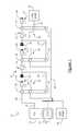
- FIG. 1is a schematic lever diagram illustration of an exemplary vehicle powertrain with a multi-mode, electrically-variable hybrid transmission in accordance with the present invention
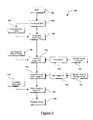
- FIG. 2is a truth table listing the engaged torque-transmitting mechanisms for each of the operating modes of the transmission illustrated in FIG. 1 ;
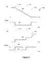
- FIG. 3is a graphical representation of various regions of operation with respect to input and output speeds of the transmission illustrated in FIG. 1 ;
- FIG. 4is a flow chart or block diagram illustrating a shift control method in accordance with the present invention.
- FIG. 5is a schematic graphical representation of selected characteristics of the clutch, plotted with respect to time, during a shift event.
- the claimed inventionis described herein in the context of a hybrid-type vehicular powertrain having a multi-mode, multi-speed, electrically-variable, hybrid transmission, which is intended solely to offer a representative application by which the present invention may be incorporated and practiced.
- the claimed inventionis not limited to the particular powertrain arrangement shown in the drawings.
- the hybrid powertrain illustrated hereinhas been greatly simplified, it being understood that further information regarding the standard operation of a hybrid powertrain, or a hybrid-type vehicle will be recognized by those having ordinary skill in the art.
- FIG. 1a lever diagram depiction of an exemplary vehicle powertrain system, designated generally as 10 .
- the powertrain 10includes a restartable engine 12 that is selectively drivingly connected to, or in power flow communication with, a final drive system 16 via a multi-mode, electrically-variable hybrid-type power transmission 14 .
- a lever diagramis a schematic representation of the components of a mechanical device such as an automatic transmission.
- Each individual leverrepresents a planetary gearset, wherein the three basic mechanical components of the planetary gear are each represented by a node. Therefore, a single lever contains three nodes: one for the sun gear member, one for the planet gear carrier member, and one for the ring gear member.
- the relative length between the nodes of each levermay be used to represent the ring-to-sun ratio of each respective gearset.
- These lever ratiosare used to vary the gear ratios of the transmission in order to achieve appropriate ratios and ratio progression.
- Mechanical couplings or interconnections between the nodes of the various planetary gear sets and other components of the transmissionare illustrated by thin, horizontal lines. Torque transmitting devices such as clutches and brakes are presented as interleaved fingers. If the device is a brake, one set of the fingers is grounded.
- the transmission 14is designed to receive at least a portion of its driving power from the engine 12 , through an input member 18 , for example.
- the transmission input member 18which is in the nature of a shaft, may be the engine output shaft (also referred to as a “crankshaft”).
- a transient torque damper(not shown) may be implemented between the engine 12 and the input member 18 of the transmission 14 .
- the engine 12transfers power to the transmission 14 , which distributes torque through a transmission output member or shaft 20 to drive the final drive system 16 , and thereby propel the vehicle (not shown).
- the engine 12may be any of numerous forms of petroleum-fueled prime movers, such as the reciprocating-piston type internal combustion engines, which includes spark-ignited gasoline engines and compression-ignited diesel engines.
- the engine 12is readily adaptable to provide its available power to the transmission 14 at a range of operating speeds, for example, from idle, at or near 600 revolutions per minute (RPM), to over 6,000 RPM.
- RPMrevolutions per minute
- the input member 18is connected to a differential gear set encased within the transmission 14 , as explained in more detail herein.
- the hybrid transmission 14utilizes one or more differential gear arrangements, preferably in the nature of three interconnected epicyclic planetary gear sets, designated generally at 24 , 26 and 28 , respectively.
- Each gear setincludes three gear members: a first, second and third member.
- these setsmay be counted “first” to “third” in any order in the drawings (e.g., left to right, right to left, etc.).
- first, second and third members of each gear setin this description and in the claims, these members may be counted or identified as “first” to “third” in any order in the drawings (e.g., top to bottom, bottom to top, etc.) for each gear set.
- the first planetary gear set 24has three gear members: a first, second and third member 30 , 32 and 34 ; respectively.
- the first member 30includes of an outer gear member (which may be referred to as a “ring gear”) that circumscribes the third member 34 , which may include of an inner gear member (which may be referred to as a “sun gear”).
- the second member 32acts as a planet carrier member. That is, a plurality of planetary gear members (which may be referred to as “pinion gears”) are rotatably mounted on the second member, planet carrier 32 .
- Each planetary gear memberis meshingly engaged with both the first member, ring gear 30 and the third member, sun gear 34 .
- the second planetary gear set 26also has three gear members: a first, second and third member 40 , 42 and 44 , respectively.
- the first member 40 of the second planetary gear set 26is an outer “ring” gear member that circumscribes the third member 44 , which is an inner “sun” gear member.
- the ring gear member 40is coaxially aligned and rotatable with respect to the sun gear member 44 .
- a plurality of planetary gear membersare rotatably mounted on the second member 42 , which acts as a planet carrier member, such that each planetary gear meshingly engages both the ring gear member 40 and the sun gear member 44 .
- the third planetary gear set 28similar to the first and second gear sets 24 , 26 , also has first, second and third members 50 , 52 and 54 , respectively.
- the second member 52shown on the middle node of the lever for the third planetary gear set 28 , is the outer “ring” gear.
- the ring gear (second member 52 )is coaxially aligned and rotatable with respect to the sun gear, third member 54 .
- the first member 50is the planet carrier in this particular gear set, and is shown on the top node.
- a plurality of planetary or pinion gear membersare rotatably mounted on the planet carrier, first member 50 .
- Each of the pinion gear membersis aligned to meshingly engage either the ring gear (second member 52 ) and an adjacent pinion gear member or the sun gear (third member 54 ) and an adjacent pinion gear member.
- first and second planetary gear sets 24 , 26each comprise simple planetary gear sets
- the third planetary gear set 28comprises a compound planetary gear set.
- each of the planet carrier members described abovecan be either a single-pinion (simple) carrier assembly or a double-pinion (compound) carrier assembly. Embodiments with long pinions are also possible.
- the first, second and third planetary gear sets 24 , 26 , 28are compounded in that the second member 32 of the first planetary gear set 24 is conjoined with (i.e., continuously connected to) the second member 42 of the second planetary gear set 26 and the third member 54 of the third planetary gear set 28 , as by a central shaft 36 . As such, these three gear members 32 , 42 , 54 are rigidly attached for common rotation.
- the engine 12is continuously connected to the first planetary gear set 24 , namely first member 30 , for example, through an integral hub plate 38 , for common rotation therewith.
- the third member 34 of the first planetary gear set 24is continuously connected, for example, by a first sleeve shaft 46 , to a first motor/generator assembly 56 , which is also referred to herein as “motor A”.
- the third member 44 of the second planetary gear set 26is continuously connected, for example, by a second sleeve shaft 48 , to a second motor/generator assembly 58 , also referred to herein as “motor B”.
- the second member 52 (ring gear) of the third planetary gear set 28is continuously connected to transmission output member 20 , for example, through an integral hub plate.
- the first and second sleeve shafts 46 , 48may circumscribe the central shaft 36 .
- a first torque transfer device 70which is herein interchangeably referred to as clutch “C 1 ”—selectively connects the first gear member 50 with a stationary member, represented in FIG. 1 by transmission housing 60 .
- the second sleeve shaft 48and thus gear member 44 and motor/generator 58 , is selectively connectable to the first member 50 of the third planetary gear set 28 through the selective engagement of a second torque transfer device 72 —which is herein interchangeably referred to as clutch “C 2 ”.
- a third torque transfer device 74which is herein interchangeably referred to as clutch “C 3 ”—selectively connects the first gear member 40 of the second planetary gear set 26 to the transmission housing 60 .
- the first sleeve shaft 46and thus third gear member 34 and first motor/generator 56 , is also selectively connectable to the first member 40 of the second planetary gear set 26 , through the selective engagement of a fourth torque transfer device 76 —which is herein interchangeably referred to as clutch “C 4 ”.
- a fifth torque transfer device 78which is herein interchangeably referred to as clutch “C 5 ”—selectively connects the input member 18 of engine 12 and the first gear member 30 of the first planetary gear set 24 to the transmission housing 60 .
- Clutch C 5is an input brake clutch, which selectively locks the input member 18 when engine 12 is off. Locking input member 18 provides more reaction for regenerative braking energy. As shown below, in reference to FIG. 2 , C 5 is not involved in the mode/gear/neutral shifting maneuvers of transmission 14 .
- the first and second torque transfer devices 70 , 72may be referred to as “output clutches.”
- the third and fourth torque transfer devices 74 , 76may be referred to as “holding clutches”.
- the various torque transfer devices 70 , 72 , 74 , 76 , 78are all friction clutches.
- other conventional clutch configurationsmay be employed, such as dog clutches, rocker clutches, and others recognizable to those having ordinary skill in the art.
- the clutches C 1 -C 5may be hydraulically actuated, receiving pressurized hydraulic fluid from one or more pumps.
- a main pump(not shown) may be operatively connected to the engine 12 and powered by the engine output or input member 18 .
- auxiliary pump 90is included to provide hydraulic fluid to the transmission 14 . Because the auxiliary pump 90 does not derive power from the engine 12 , and instead derives power from one of the batteries or energy storage devices, auxiliary pump 90 is capable of supplying pressurized fluid while the vehicle is in an engine-off mode. Auxiliary pump 90 may be used, without limitation, for actuation of clutches C 1 -C 5 , lubrication of components, and cooling of the various elements of transmission 14 .
- the transmission output shaft 20is operatively connected to the final drive system (or “driveline”).
- the drivelinemay include a front or rear differential, or other torque transfer device, which provides torque output to one or more wheels through respective vehicular axles or half-shafts (not shown).
- the wheelsmay be either front or rear wheels of the vehicle on which they are employed, or they may be a drive gear of a track vehicle.
- the final drive systemmay include any known configuration, including front wheel drive (FWD), rear wheel drive (RWD), four-wheel drive (4WD), or all-wheel drive (AWD), without altering the scope of the claimed invention.
- All of the planetary gear sets 24 , 26 , 28 , as well as the first and second motor/generators 56 , 58 (motor A and motor B,)are preferably coaxially oriented about the intermediate central shaft 36 or another axis.
- Motor A or motor Bmay take on an annular configuration, permitting one or both to generally circumscribe the three planetary gear sets 24 , 26 , 28 .
- Such a configurationmay reduce the overall envelope, i.e., the diametrical and longitudinal dimensions, of the hybrid transmission 14 are minimized.
- the hybrid transmission 14receives input motive torque from a plurality of torque-generative devices.
- torque-generative devicesinclude the engine 12 and the motors/generators 56 , 58 as a result of energy conversion from fuel stored in a fuel tank or electrical potential stored in an electrical energy storage device (neither of which is shown).
- motor A and motor Bmay operate individually or in concert—in conjunction with the planetary gear sets and selectively-engageable torque-transmitting mechanisms—to rotate the transmission output shaft 20 .
- motor A and motor Bare preferably configured to selectively operate as both a motor and a generator.
- motor A and motor Bare capable of converting electrical energy to mechanical energy (e.g., during vehicle propulsion), and further capable of converting mechanical energy to electrical energy (e.g., during regenerative braking or during periods of excess power supply from engine 12 ).
- an electronic control apparatushaving a distributed controller architecture is shown schematically in an exemplary embodiment as a microprocessor-based electronic control unit (ECU) 80 .
- the ECU 80includes a storage medium with a suitable amount of programmable memory, collectively represented at 82 , that is programmed to include, without limitation, an algorithm or method 100 of regulating operation of a multi-mode hybrid transmission, as will be discussed in further detail below with respect to FIG. 4 .
- the control apparatusis operable, as described hereinafter, to provide coordinated system control of the powertrain 10 schematically depicted and described herein.
- the constituent elements of the control apparatusmay be a subset of an overall vehicle control system.
- the control systemis operable to synthesize pertinent information and inputs, and execute control methods and algorithms to control various actuators to achieve control targets.
- the control systemmonitors target and parameters including, without limitation: fuel economy, emissions, performance, driveability, and protection of drivetrain hardware—such as, but not limited to, the engine 12 , transmission 14 , motor A, motor B, and final drive 16 .
- the distributed controller architecturemay include a Transmission Control Module (TCM), an Engine Control Module (ECM), a Transmission Power Inverter Module (TPIM), and a Battery Pack Control Module (BPCM).
- TCMTransmission Control Module
- ECMEngine Control Module
- TPIMTransmission Power Inverter Module
- BPCMBattery Pack Control Module
- HCPHybrid Control Module
- a User Interfaceis operatively connected to a plurality of devices (not shown) through which a vehicle operator typically controls or directs operation of the powertrain.
- exemplary vehicle operator inputs to the user interfaceinclude an accelerator pedal, a brake pedal, transmission gear selector, vehicle speed cruise control, and other inputs recognizable to those having ordinary skill in the art.
- Each of the aforementioned controllerscommunicates with other controllers, sensors, actuators, etc., via a control area network (CAN) bus or communication architecture.
- CANcontrol area network
- the CAN busallows for structured communication of control parameters and commands between the various controllers.
- the communication protocol utilizedis application-specific. For example, and without limitation, one useable communication protocol is the Society of Automotive Engineers standard J1939.
- the CAN bus and appropriate protocolsprovide for robust messaging and multi-controller interfacing between the aforementioned controllers, and other controllers providing functionality such as antilock brakes, traction control, and vehicle stability.
- the engine control moduleis operatively connected to, and in communication with, the engine 12 .
- the engine control moduleis configured to acquire data from a variety of sensors and control a variety of actuators of the engine 12 over a plurality of discrete lines.
- the engine control modulereceives an engine torque command from the hybrid control module, generates a desired axle torque, and an indication of actual engine torque, which is communicated to the hybrid control module.
- Various other parameters that may be sensed by the engine control moduleinclude engine coolant temperature, engine input speed to the transmission, manifold pressure, and ambient air temperature and pressure.
- Various actuators that may be controlled by the engine control moduleinclude, without limitation, fuel injectors, ignition modules, and throttle control modules.
- the transmission control moduleis operatively connected to the transmission 14 , and functions to acquire data from a variety of sensors and provide command signals to the transmission 14 .
- Inputs from the transmission control module to the hybrid control modulemay include estimated clutch torques for each of the clutches C 1 -C 5 , and rotational speed of the transmission output shaft 20 .
- Additional actuators and sensorsmay be used to provide additional information from the transmission control module to the hybrid control module for control purposes.
- Each of the aforementioned controllersmay be a general-purpose digital computer, generally including a microprocessor or central processing unit, read only memory (ROM), random access memory (RAM), electrically programmable read only memory (EPROM), high speed clock, analog to digital (A/D) and digital to analog (D/A) circuitry, and input/output circuitry and devices (I/O) and appropriate signal conditioning and buffer circuitry.
- ROMread only memory
- RAMrandom access memory
- EPROMelectrically programmable read only memory
- high speed clockclock
- A/Danalog to digital
- D/Adigital to analog
- I/Oinput/output circuitry and devices
- Each controllerhas a set of control algorithms, including resident program instructions and calibrations stored in ROM and executed to provide the respective functions of each computer. Information transfer between the various computers may be accomplished using the aforementioned CAN.
- the supervisory hybrid control module controller and one or more of the other controllers described above with respect to FIG. 1determine required transmission output torque.
- Selectively operated components of the hybrid transmission 14are appropriately controlled and manipulated to respond to the operator demand.
- the hybrid control moduledetermines an output torque for the transmission, which affects how and when the vehicle accelerates or decelerates. Final vehicle acceleration is affected by other variables, including such factors as road load, road grade, and vehicle mass.
- the hybrid control modulemonitors the parametric states of the torque-generative devices, and determines the output of the transmission required to arrive at the desired torque output. Under the direction of the hybrid control module, the transmission 14 operates over a range of output speeds from slow to fast in order to meet the operator demand.
- the ECU 80also receives frequency signals from sensors for processing into input member 18 speed, N i , and output member 20 speed, N o , for use in the control of transmission 14 .
- the system controllermay also receive and process pressure signals from pressure switches (not shown) for monitoring clutch application chamber pressures. Alternatively, pressure transducers for wide range pressure monitoring may be employed. Pulse-width modulation (PWM) and/or binary control signals are transmitted by the controller 80 to transmission 14 for controlling fill and drain of clutches C 1 -C 5 for application and release thereof.
- PWMPulse-width modulation
- binary control signalsare transmitted by the controller 80 to transmission 14 for controlling fill and drain of clutches C 1 -C 5 for application and release thereof.
- controller 80may receive transmission fluid sump temperature data, such as from thermistor inputs (not shown), to derive a sump temperature. Controller 80 may provide PWM signals derived from input speed, N i , and sump temperature for control of line pressure via one or more regulators.
- Fill and drain of clutches C 1 -C 5may be effectuated, for example, by solenoid controlled spool valves responsive to PWM and binary control signals. Trim valves may be employed using variable bleed solenoids to provide precise placement of the spool within the valve body and correspondingly precise control of clutch pressure during apply. Similarly, one or more line pressure regulators (not shown) may be utilized for establishing regulated line pressure in accordance with the control signal. Clutch slip speeds across clutches may be derived from, for example: transmission input speed, output speed, motor A speed, and/or motor B speed.
- the multi-mode, electrically-variable, hybrid transmission 14is configured for several transmission operating modes.
- the truth table provided in FIG. 2presents an exemplary engagement schedule of the torque-transmitting mechanisms C 1 -C 4 to achieve the array of operating states or modes.
- the various transmission operating modes described in the tableindicate which of the specific clutches C 1 -C 4 are engaged (actuated), and which are released (deactivated) for each of the operating modes.
- ratio changes in transmission 14may be performed such that torque disturbances are minimized, and the shifts are smooth and unobjectionable to the vehicle occupants.
- release and application of clutches C 1 -C 4should be performed in a manner which consumes the least amount of energy, and does not negatively impact durability of the clutches.
- One major factor affecting these considerationsis the torque at the clutch being controlled, which may vary significantly in accordance with such performance demands as acceleration and vehicle loading.
- Improved shiftsmay be accomplished by a zero, or close to zero, reactive torque condition at the clutches at the time of application or release, which condition follows substantially zero slip across the clutch. Clutches having zero slip across the clutch may be referred to as operating synchronously.
- Electrically-variable operating modesmay be separated into four general classes: input-split modes, output-split modes, compound-split modes, and series modes.
- input-split modeone motor/generator (such as either motor A or motor B) is geared such that its speed varies in direct proportion to the transmission output, and another motor/generator (such as the other of motor A or motor B) is geared such that its speed is a linear combination of the input and output member speeds.
- an output-split modeone motor/generator is geared such that its speed varies in direct proportion to the transmission input member, and the other motor/generator is geared such that its speed is a linear combination of the input member and the output member speeds.
- a compound-split modehowever, has both motor/generators geared such that their speeds are linear combinations of the input and output member speeds, but neither is in direct proportion to either the speed of the input member or the speed of the output member.
- one motor/generatorwhen operating in a series mode, one motor/generator is geared such that its speed varies in direct proportion to the speed of the transmission input member, and another motor/generator is geared such that its speed varies in direct proportion to the speed of the transmission output member.
- one motor/generatorWhen operating in series mode, there is no direct mechanical power transmission path between the input and output members and therefore all power must be transmitted electrically.
- a and bare coefficients determined by the transmission gearing.
- An electrically-variable transmissionmay also contain one or more fixed-gear (FG) modes.
- FG modesresult from closing (i.e., actuating) one additional clutch than the number required to select an electrically-variable mode.
- FG modesthe speed of the input and each motor are proportional to the speed of the output. Thus, these modes have only one speed degree of freedom.
- the torque and speed equations of this class of modestake the form:
- An electrically-variable transmissionmay also be configured for one or more modes with three speed degrees of freedom. These modes may or may not include reaction torque sources such that the transmission is capable of producing output torque proportional to engine torque or motor torque. If a mode with three speed degrees of freedom is capable of producing output torque, the torques of the engine and any motor connected as a reaction to the engine torque will generally be proportional to the output torque. If a motor is not connected as a reaction to the engine torque, its torque can be commanded to control its speed independently of the transmission input and output speed.
- ETCelectric torque converter
- motor Bserves as a reaction member and its torque is proportional to output torque when operating in the ETC mode. If a 1,2 is zero, motor B is disconnected and its torque is not determined by the output torque. If a 1,3 is nonzero, the engine can contribute to output torque during operation in the fixed-gear mode. If a 1,3 is zero, the input is disconnected and its torque is not determined by the output torque. If all of a 1,1 , a 1,2 , and a 1,3 are zero, the mode is a neutral mode that is not capable of producing output torque.
- Neutral 1There are four neutral modes presented in FIG. 2 .
- Neutral 1all clutches are released.
- Neutral 1may be utilized when the entire vehicle is stopped and in an off-state, and thus there is no power distribution, electrical, mechanical, or otherwise, being actively distributed throughout the powertrain 10 .
- a 12-volt starting-lighting-and-ignition (SLI) batterymay be used for engine start.
- the first and second planetary gear sets 24 , 26cooperate with the first and second motor/generators 56 , 58 , along with the selective engagement of the first and second clutches C 1 , C 2 , to constitute an electric torque converter (ETC).
- ETCelectric torque converter
- the electric output of motor A and/or motor Bdepending upon the active control schedule, can be adapted to control the transfer of torque from the engine 12 through the transmission differential gearing to the output member 20 .
- ETC 1 Modeis established by engaging the first clutch C 1 .
- motor Areacts engine 12 with the first and third planetary gear sets 24 , 28 , and motor B freewheels.
- ETC 1 Modethe stationary vehicle can be smoothly started with the engine 12 held at a suitable speed by gradually increasing the amount of electric power generated by motor A—i.e., the reaction force of motor A.
- ETC 2 Modealso known as “compound ETC”
- compound ETCcan be initiated by engaging clutch C 2 , and disengaging the remaining clutches.
- motor Areacts engine 12 with the first and third planetary gear sets 24 , 28
- motor Breacts engine 12 and motor A to the output member 20 .
- the distribution of engine torqueis manipulated through the cooperative management of the amount of electric power output generated by motor A and motor B.
- the third ETC modecan be initiated by engaging both clutch C 1 and clutch C 2 . Similar to ETC 1 Mode, motor A reacts the engine 12 with the first and third planetary gear sets 24 , 28 . However, in this instance, motor B is grounded to the transmission housing 60 . In ETC 12 Mode, the vehicle can be smoothly accelerated with the engine 12 held at a suitable speed by gradually increasing the reaction force generated by motor A; which may be proportional to the electric power generated by motor A.
- the transmission 14can utilize the ETC mode clutch control schedule to vary the amount of electric energy generated by motor A so as to gradually increase the drive torque of motor A and/or motor B. For example, if the transmission 14 is shifted into ETC 1 Mode when the engine 12 is in an off-state, the engine 12 will create a reaction force, by way of input member 18 . The motive output of the motor A can then be controlled, and a continuous and uninterrupted transmission output torque maintained, without having to turn the engine 12 on.
- the exemplary powertrain 10 described hereinhas three fixed-gear (FG), or “direct,” modes of operation.
- FGfixed-gear
- the vehicleIn all fixed-gear modes of this embodiment of transmission 14 , the vehicle is driven in the forward direction by operation of the engine 12 .
- the selective engagement of clutches C 1 , C 3 and C 4shifts the transmission 14 into FG 1 Mode.
- motor AIn FG 1 , motor A is grounded, and the engine drives the first planetary gear set 24 to the third planetary gear set 28 and, thus, the output member 20 .
- FG 2 Modeis achieved by the selective engagement of clutches C 1 , C 2 and C 4 .
- FG 2motor B is grounded, and the engine drives the first and second planetary gear sets 24 , 26 to the third planetary gear set 28 and, thus, the output member 20 .
- FG 3 Modeis achieved by the selective engagement of clutches C 2 , C 3 and C 4 .
- motor Ais locked, and the engine drives the first planetary gear set 24 to the second and third planetary gear sets 26 , 28 and the output member 20 .
- the output member speed N ois directly proportional to input member speed N i and the selected gear ratio.
- N iN o ⁇ GR.
- the transmission 14may also operate in four electrically-variable transmission (EVT) modes.
- EVT 1 and EVT 4the transmission 14 is operating in an input-split mode of operation, wherein the output speed N o of the transmission 14 is proportional to the speed of one motor/generator 56 , 58 (motor A or motor B).
- EVT 1 Modeis achieved through the selective engagement of the first and third clutches C 1 and C 3 .
- motor Afunctions to react the engine 12 with the first planetary gear set 24 , to the third planetary gear set 28 , and the output member 20 ; while motor B drives the second and third planetary gear sets 26 , 28 .
- Motor Apropels the vehicle in EVT 1 .
- the transmission 14may be selectively shifted into EVT 4 Mode by actuating clutch C 2 and clutch C 3 .
- motor Afunctions to react the engine 12 with the first planetary gear set 24 , to the second and third planetary gear sets 26 , 28 , and the output member 20 , while motor B drives the second and third planetary gear sets 26 , 28 .
- Motor Bpropels the vehicle in EVT 4 .
- EVT 2 and EVT 3the transmission 14 is operating in a compound-split mode, wherein the output speed No of the transmission 14 is not proportional to the speed of a single motor/generator, but is rather an algebraic linear combination of the speeds of both motor/generators. More particularly, EVT 2 is achieved through the selective engagement of the first and fourth clutches C 1 , C 4 . In this mode, motor A and motor B operate to react the engine 12 with the first and second planetary gears sets. Alternatively, the transmission 14 may be selectively shifted into EVT 3 Mode by actuating clutch C 2 and clutch C 4 . When operating in EVT 3 Mode, the two motor/generator assemblies 56 , 58 react the engine 12 with all three planetary gear sets 24 , 26 , 28 .
- FIG. 3a plot of transmission output speed, N o , along the horizontal axis versus input speed, N i , across the vertical axis is illustrated.
- FIG. 3is only a graphical representation of exemplary regions of operation for each operating mode with respect to input and output speeds of this embodiment of transmission 14 .
- Synchronous operation in FG 1the input speed and output speed relationships where clutches C 1 , C 3 and C 4 are operating with substantially zero slip speed thereacross—is represented by line 91 .
- line 91represents an input and output speed relationship at which substantially synchronous shifting between EVT modes can occur.
- FG 1is also a range at which direct mechanical coupling from input to output can be effected by simultaneous application of clutches C 1 , C 3 and C 4 —i.e., fixed- or direct-ratio.
- Synchronous operation in FG 2the input speed and output speed relationships where clutches C 1 , C 2 and C 4 are operating with substantially zero slip speed thereacross—is represented by line 93 .
- To the left of the shift ratio line 91is an exemplary region of operation for the first EVT mode, EVT 1 , wherein both C 1 and C 3 are applied, and C 2 and C 4 are released.
- To the right of the shift ratio line 91 and left of shift ratio line 93is an exemplary region of operation for the second EVT mode, EVT 2 , wherein C 1 and C 4 are applied, and C 2 and C 3 are released.
- regions of operation specified abovemay be generally favored for operation of the hybrid transmission 14 , it is not meant to imply that the various EVT regions of operation depicted in FIG. 3 cannot or do not overlap. Generally, however, it may be preferred to operate in the specified regions because each particular mode of operation preferably employs gear sets and motor hardware particularly well suited in various aspects (e.g., mass, size, cost, inertial capabilities, etc.) for that region. Similarly, while the individual regions of operation specified above are generally preferred for the particular modes of operation indicated, it is not meant to imply that the regions of operation for the individual EVT modes cannot be switched.
- a shift into Mode 1may be considered a downshift and is associated with a higher gear ratio in accordance with the relationship of N i /N o .
- a shift into Mode 4is considered an upshift, and is associated with a lower gear ratio in accordance with the relationship of N i /N o .
- other mode-to-mode shift sequencesare feasible. For example, a shift from EVT 1 to EVT 3 is also an upshift, while a shift from EVT 4 to EVT 2 is considered a downshift.
- FIG. 4shows a control algorithm or method for regulating operation of a clutch or clutches of multi-mode hybrid transmission generally at 100 .
- FIG. 5shows graphs of selected characteristics of the clutch, plotted with respect to time, during a shift event 200 which may coincide with portions of the method 100 shown in FIG. 4 . From top to bottom, FIG. 5 shows clutch slip speed, N c ; the time rate of change (first derivative) of clutch slip speed, N c dot; pressure of the clutch, P c ; and state of the pressure switch or variable bleed solenoid monitoring and controlled flow of hydraulic fluid to the clutch.
- Method 100begins at an initiation or start 102 , which may coincide with a vehicle operator turning on the ignition of the vehicle, or may coincide with another initiation event.
- the hybrid control module and ECU 80may be monitoring various attributes of the vehicle and hybrid powertrain 10 .
- the method 100will be described with specific reference to clutch C 3 . However, the method 100 may be implemented for control and actuation of any of the clutches C 1 -C 5 .
- the hybrid control modulemay request or command that the transmission 14 perform a shift event (such as the shift event 200 of FIG. 5 ), at step 104 .
- method 100then proceeds to command the clutch C 3 to begin synchronization by controlling the magnitude of the slip speed to zero. Controlling slip speed toward zero may include decreasing or increasing the actual speed off the elements connectable by the clutch C 3 .
- method 100may include commanding the auxiliary pump 90 to turn on at step 108 , which may occur contemporaneously or after the shift is commanded at step 104 .
- the hybrid control systemwaits a predetermined amount of time after the shift is commanded and then begins to fill the clutch at a high flow rate. This may cause the clutch to engage either too early or too late, depending upon the fill time required to take the clutch from empty (completely disengaged) to full (completely engaged). Also the pump pressure available to fill the clutch may affect the fill time and cause late engagement if insufficient pressure is available for the traditional hydraulic clutch control.
- Commanding synchronization of the clutch C 3 at step 106occurs at or near line 210 in FIG. 5 .
- the previous, or baseline, characteristics of clutch C 3end as the transmission 14 begins preparing clutch C 3 for engagement.
- synchronizationinvolves stopping rotation of the first member 40 of the second planetary gear set 26 (the ring gear of P 2 ).
- Synchronization of clutch C 3causes N c dot, shown as curve 204 in FIG. 5 , to move from zero to a non-zero value as N c slows down.
- Method 100then begins filling the clutch C 3 to a pre-fill target volume at step 110 .
- Thiscauses fluid to move into the piston of clutch C 3 and increases the pressure of clutch C 3 , P c , which is shown on curve 206 of FIG. 5 .
- Pressure switch state of clutch C 3is shown on curve 208 of FIG. 5 .
- Beginning to fill clutch C 3causes the pressure switch to move from an “off” or regulated-flow state to an “on” or full-feed state.
- the pressure switch signalis often communicated as either a “0” or “1” digital logic signal. Either of the pressure switch on/off states shown in FIG. 5 may coincide with either the 0 or 1 digital logic states of the switch signal.
- Pre-filling the clutch C 3 to the pre-fill target volumereadies clutch C 3 to be fully-actuated and engaged with reduced lag time or delay, when compared to filling an empty clutch in order to effect engagement. Complete torque transfer across clutch C 3 does not occur until the clutch C 3 has been filled to an actual touch point volume.
- the pre-fill target volumemay be set to approximately 80 percent of a first predicted touch point volume, as shown in optional step 112 .
- the clutchmay also be controlled based upon clutch pressure, P c , which is related to clutch volume.
- the pre-fill target volumemay be set to a more-specific level of between 80 to 90 percent of the predicted touch point volume.
- the first predicted touch point volume (and pressure)may have been determined through experiment or in the design stages of the powertrain 10 . As described below, the method 100 may adjust the predicted touch point volume to adjust for changing conditions of the clutch C 3 and transmission 14 .
- clutch C 3is held at the pre-fill target volume until the hybrid control system determines that the shift event 200 for clutch C 3 is ready to be completed.
- Method 100holds the volume of C 3 at step 114 until a trigger point is reached.
- the trigger pointis shown as line 212 in FIG. 5 and is calculated or determined by the amount of time needed to finish filling clutch C 3 to the touch point volume.
- Holding clutch C 3 at the pre-fill target volume(until the trigger point 212 is reached) is shown beginning at line 218 of FIG. 5 , and occurs by turning the pressure switch off and regulating or maintaining P c at substantially constant pressure.
- Touch point volumecoincides with clutch C 3 reaching a touch point, which is shown at 214 in FIG. 5 , and the point at which clutch C 3 begins transferring full torque between the ring gear 40 and the transmission housing 60 .
- the difference between the trigger point 212 and the touch point 214is the effective fill time of the clutch C 3 when using the pre-fill actuation method.
- method 100After reaching the trigger point 212 , method 100 begins completing the shift event 200 by filling the clutch C 3 to the first predicted touch point volume at step 116 .
- Method 100utilizes the first predicted touch point volume because the actual touch point volume may not be known due to variations in temperature of the hydraulic fluid, leaks in clutch C 3 or elsewhere in transmission 14 , or variations in pumping pressure.
- the first predicted touch point volumeis greater than the pre-fill target volume.
- the actual touch point volumemay be greater or less than the first predicted touch point volume. If the first predicted touch point does not cause actual, full engagement of clutch C 3 , the pressure switch remains open and will therefore continue filling the clutch piston until the actual touch point.
- the method 100may complete synchronization—by bringing slip speed to substantially zero—prior to fully engaging the clutch in step 120 .
- Completing synchronizationis shown in FIG. 4 as optional step 118 and may occur prior to, along with, or after filling clutch C 3 to the predicted touch point in step 116 .
- the trigger point 212may be calculated or set to occur substantially simultaneously with the completion of synchronization of the clutch C 3 .
- the trigger point 212and start of filling the clutch to the predicted touch point in step 116 , occurs when the slip speed, N c , reaches zero.
- pre-filling the clutch C 3 to the pre-fill target volumemay begin simultaneously with commanding the shift, shown at line 210 .
- the hybrid control systembegins preparing clutch C 3 for the shift as soon as the shift is commanded. However, if fill times were decreased, the hybrid control system may delay pre-filling clutch C 3 until after the shift is commanded and synchronization has already begun.
- the trigger point 212may be adjusted or calculated during the shift event 200 .
- the method 100may determine the time rate of change of the slip speed in optional step 122 .
- This first derivative of slip speed, N c dotis then used at step 124 to set the trigger point 212 .
- Step 124sets the trigger point 212 by calculating when slip speed, N c , will reach zero and subtracting the effective fill time from the predicted reaching of zero slip speed.
- the predicted touch volumeis reached substantially coincidentally with complete synchronization of clutch C 3 , which is the earliest point where a synchronous shift can occur.
- the method 100may optionally monitor the actual pressure (P c ) of the clutch C 3 .
- the method 100is able to calculate or estimate the actual touch point volume of the shift events. This is shown in FIG. 4 as step 126 .
- These monitored shiftsmay be either shifts using the pre-fill actuation scheme or may use standard clutch actuation techniques.
- the method 100calculates a flow model, shown at optional step 130 , which is updated every time a shift event occurs to better determine the actual touch point volume of the clutch C 3 .
- the flow modelmay then be used to determine the amount of fluid accumulated in the clutch piston and therefore determine when a sufficient amount of fluid has entered the clutch piston to move clutch C 3 to the pre-fill volume.
- method 100it is within the scope of the claimed invention to omit steps from method 100 , include additional steps in method 100 , and/or modify the order presented in FIG. 4 .
- the method 100generally represents only a single shift sequence or event. However, it is expected, as indicated above, that the method 100 be applied in a systematic and repetitive manner. The use of such terminology as “sensing”, “detecting”, “measuring”, “calculating”, or otherwise “determining” is not intended as limiting, and should be considered interchangeable.
Landscapes
- Engineering & Computer Science (AREA)
- Chemical & Material Sciences (AREA)
- Combustion & Propulsion (AREA)
- Mechanical Engineering (AREA)
- Transportation (AREA)
- Physics & Mathematics (AREA)
- Fluid Mechanics (AREA)
- General Engineering & Computer Science (AREA)
- Hybrid Electric Vehicles (AREA)
- Electric Propulsion And Braking For Vehicles (AREA)
Abstract
Description
where a and b are coefficients determined by the transmission gearing. The type of EVT mode can be determined from the structure of the matrix of b coefficients. That is, if b2,1=b1,2=0 or b1,1=b2,2=0, the mode is a series mode. If b1,1=0 or b1,2=0, the mode is an input split mode. If b2,1=0 or b2,2=0, the mode is an output split mode. If each of b1,1, b1,2, b2,1, and b2,2are nonzero, for example, the mode is a compound split mode.
where a and b are again coefficients determined by the transmission gearing. If b1,1is nonzero, motor A can contribute to output torque during operation in the fixed-gear mode. If b1,2is nonzero, motor B can contribute to output torque during operation in the fixed-gear mode. If b1,3is nonzero, the engine can contribute to output torque during operation in the fixed-gear mode. If b1,3is zero, the mode is an electric-only fixed-gear mode.
where a and b are coefficients determined by the transmission gearing. If a1,1is nonzero, motor A serves as a reaction member and its torque is proportional to output torque when operating in the ETC mode. If a1,1is zero, motor A is disconnected and its torque is not determined by the output torque. If a1,2is nonzero, motor B serves as a reaction member and its torque is proportional to output torque when operating in the ETC mode. If a1,2is zero, motor B is disconnected and its torque is not determined by the output torque. If a1,3is nonzero, the engine can contribute to output torque during operation in the fixed-gear mode. If a1,3is zero, the input is disconnected and its torque is not determined by the output torque. If all of a1,1, a1,2, and a1,3are zero, the mode is a neutral mode that is not capable of producing output torque.
Claims (14)
Priority Applications (3)
| Application Number | Priority Date | Filing Date | Title |
|---|---|---|---|
| US12/468,096US8066620B2 (en) | 2009-05-19 | 2009-05-19 | Method of clutch actuation for hybrid transmissions |
| DE102010020595.8ADE102010020595B4 (en) | 2009-05-19 | 2010-05-14 | Method of clutch actuation for hybrid transmissions |
| CN2010101865655ACN101890955B (en) | 2009-05-19 | 2010-05-19 | Method of clutch actuation for hybrid transmissions |
Applications Claiming Priority (1)
| Application Number | Priority Date | Filing Date | Title |
|---|---|---|---|
| US12/468,096US8066620B2 (en) | 2009-05-19 | 2009-05-19 | Method of clutch actuation for hybrid transmissions |
Publications (2)
| Publication Number | Publication Date |
|---|---|
| US20100298089A1 US20100298089A1 (en) | 2010-11-25 |
| US8066620B2true US8066620B2 (en) | 2011-11-29 |
Family
ID=43049477
Family Applications (1)
| Application Number | Title | Priority Date | Filing Date |
|---|---|---|---|
| US12/468,096Expired - Fee RelatedUS8066620B2 (en) | 2009-05-19 | 2009-05-19 | Method of clutch actuation for hybrid transmissions |
Country Status (3)
| Country | Link |
|---|---|
| US (1) | US8066620B2 (en) |
| CN (1) | CN101890955B (en) |
| DE (1) | DE102010020595B4 (en) |
Cited By (6)
| Publication number | Priority date | Publication date | Assignee | Title |
|---|---|---|---|---|
| US20110070999A1 (en)* | 2009-09-18 | 2011-03-24 | Soliman Ihab S | Control of an Engine Restart in a Hybrid Electric Vehicle |
| US8483898B2 (en)* | 2010-08-05 | 2013-07-09 | GM Global Technology Operations LLC | Method and apparatus for controlling speed of an electric pump in a vehicle |
| US20150072830A1 (en)* | 2012-04-02 | 2015-03-12 | Daimler Ag | Hybrid Electric Vehicle Control Device |
| US20150175151A1 (en)* | 2013-12-19 | 2015-06-25 | Robert Bosch Gmbh | Method for operating a hybrid drive device |
| US9897198B2 (en)* | 2015-10-21 | 2018-02-20 | Hyundai Autron Co., Ltd. | Apparatus for calculating filling time of automatic transmission and control method thereof |
| US20230264681A1 (en)* | 2022-02-23 | 2023-08-24 | Ford Global Technologies, Llc | Adaptive controls of engine disconnect clutch |
Families Citing this family (18)
| Publication number | Priority date | Publication date | Assignee | Title |
|---|---|---|---|---|
| US8066620B2 (en)* | 2009-05-19 | 2011-11-29 | GM Global Technology Operations LLC | Method of clutch actuation for hybrid transmissions |
| DE102010039172B4 (en)* | 2010-08-11 | 2023-12-07 | Zf Friedrichshafen Ag | Method for determining an application actuation pressure value of a frictional switching element |
| US8412397B2 (en)* | 2011-02-10 | 2013-04-02 | GM Global Technology Operations LLC | Clutch fill command based on clutch slip speed profile synchronization prediction |
| US8989930B2 (en)* | 2011-06-17 | 2015-03-24 | GM Global Technology Operations LLC | Method and apparatus for controlling an engine disconnect clutch in a powertrain system |
| US8827865B2 (en)* | 2011-08-31 | 2014-09-09 | GM Global Technology Operations LLC | Control system for a hybrid powertrain system |
| US9097294B2 (en) | 2012-08-09 | 2015-08-04 | GM Global Technology Operations LLC | Control of clutch fill command based on hydraulic state of oncoming clutch |
| CN104455387B (en)* | 2014-10-22 | 2017-02-08 | 盛瑞传动股份有限公司 | Multi-clutch control method and system applicable to multi-gear hydraulic automatic transmission |
| EP3221606B1 (en) | 2014-11-19 | 2018-09-12 | Gkn Automotive Ltd. | Method for operating a clutch |
| KR102375136B1 (en)* | 2017-05-30 | 2022-03-17 | 현대자동차주식회사 | Method for learning touch point of transmission |
| JP2019006173A (en)* | 2017-06-21 | 2019-01-17 | 株式会社ジェイテクト | Auxiliary driving device |
| DE102018106174A1 (en)* | 2018-03-16 | 2019-09-19 | Schaeffler Technologies AG & Co. KG | Method for controlling a clutch actuator |
| BE1026305B1 (en)* | 2018-05-25 | 2019-12-23 | Punch Powertrain Nv | A powertrain for a vehicle and method for driving a powertrain in a vehicle |
| CN108591377A (en)* | 2018-06-20 | 2018-09-28 | 浙江吉利控股集团有限公司 | Three clutch hybrid gearboxes |
| BE1028064B1 (en)* | 2020-02-18 | 2021-09-13 | Punch Powertrain Psa E Trans Nv | Method for determining a coupling point of engagement |
| CN115066566A (en)* | 2020-03-12 | 2022-09-16 | 舍弗勒技术股份两合公司 | Friction device and method for determining a characteristic variable of a pressure-controlled friction device |
| CN113954817B (en)* | 2021-03-02 | 2023-12-01 | 长城汽车股份有限公司 | Gear shifting method of hybrid electric vehicle, controller and vehicle |
| US11692622B2 (en)* | 2021-08-02 | 2023-07-04 | Ford Global Technologies, Llc | Transmission shift with pressure controlled cleaning pulses |
| US20230077695A1 (en)* | 2021-09-10 | 2023-03-16 | Zero Emission Systems, Llc | Operation of a hybrid vehicle |
Citations (64)
| Publication number | Priority date | Publication date | Assignee | Title |
|---|---|---|---|---|
| US5058460A (en)* | 1990-01-11 | 1991-10-22 | General Motors Corporation | Clutch-to-clutch control in an automatic transmission |
| US5070747A (en)* | 1989-12-26 | 1991-12-10 | General Motors Corporation | Adaptive powered downshift control of an automatic transmission |
| US5072390A (en)* | 1989-12-26 | 1991-12-10 | General Motors Corporation | Adaptive control of an automatic transmission |
| US5079970A (en)* | 1990-10-24 | 1992-01-14 | General Motors Corporation | Acceleration-based control of power-on downshifting in an automatic transmission |
| US5314050A (en)* | 1992-12-09 | 1994-05-24 | Eaton Corporation | Clutch mode control logic |
| US5475595A (en)* | 1991-10-09 | 1995-12-12 | Toyota Jidosha Kabushiki Kaisha | Speed stage shifting of automatic transmission by composite control phases employing common target parameter |
| US5551930A (en)* | 1995-04-13 | 1996-09-03 | Caterpillar Inc. | Adaptive control method for an automatic transmission |
| US5580332A (en)* | 1995-04-13 | 1996-12-03 | Caterpillar Inc. | Method for determining the fill time of a transmission clutch |
| US5611750A (en)* | 1994-07-20 | 1997-03-18 | Toyoda Jidosha Kabushiki Kaisha | Slip control apparatus for motor vehicle lock-up clutch |
| US5779595A (en)* | 1994-07-13 | 1998-07-14 | Toyota Jidosha Kabushiki Kaisha | Slip control apparatus for motor vehicle lock-up clutch |
| US5803869A (en)* | 1997-03-17 | 1998-09-08 | General Motors Corporation | Automatic transmission auto neutral clutch controls with intermittent slip and a method of control |
| US5950789A (en)* | 1998-04-27 | 1999-09-14 | Caterpillar Inc. | End of fill detector for a fluid actuated clutch |
| US6039674A (en)* | 1999-03-26 | 2000-03-21 | Daimlerchrysler Corporation | Quick learn procedure for fill volumes of an electronically controlled automatic transmission |
| US6258010B1 (en)* | 2000-03-14 | 2001-07-10 | General Motors Corporation | Transmission shifting hydraulic control system |
| US6285942B1 (en)* | 2000-03-20 | 2001-09-04 | General Motors Corporation | Flow-based on-coming clutch fill control for an automatic transmission |
| US6375596B1 (en)* | 2000-09-12 | 2002-04-23 | Eaton Corporation | Control to determine input shaft direction of rotation |
| USH2031H1 (en)* | 1998-12-21 | 2002-06-04 | Caterpillar Inc. | Apparatus and method for controlling the end of fill of a fluid actuated clutch |
| US20030029691A1 (en)* | 2001-08-10 | 2003-02-13 | Lorentz Timothy A. | Power take-off clutch control system |
| US20030051969A1 (en)* | 2001-09-15 | 2003-03-20 | Marco Reinards | Clutch control system and method |
| US6551208B1 (en)* | 2001-10-18 | 2003-04-22 | General Motors Corporation | Three-mode, compound-split, electrically-variable transmission |
| US20030079952A1 (en)* | 2001-10-15 | 2003-05-01 | Smith Anthony L. | Method for slip power management of a controllable viscous fan drive |
| US6640950B2 (en)* | 2001-12-28 | 2003-11-04 | Caterpillar Inc. | Fluid clutch fill detection system and method |
| US6730000B1 (en)* | 2002-12-09 | 2004-05-04 | Daimlerchrysler Corporation | Interactive process during engine idle stop mode |
| US20040111203A1 (en)* | 2002-12-05 | 2004-06-10 | Nissan Motor Co., Ltd. | Torque-converter slip control system |
| US20040192506A1 (en)* | 2003-03-28 | 2004-09-30 | Toyota Jidosha Kabushiki Kaisha | Control apparatus and method for lock-up clutch of vehicle |
| US20050076958A1 (en)* | 2003-10-14 | 2005-04-14 | Foster Michael D. | Control apparatus, method and diagnostic for hydraulic fill and drain |
| US6915890B1 (en)* | 2003-12-18 | 2005-07-12 | General Motors Corporation | Learning method for oncoming clutch fill level and volume |
| US20050257632A1 (en)* | 2004-05-21 | 2005-11-24 | Runde Jeffrey K | Method of determining initial transmission calibration |
| US6997299B2 (en)* | 2003-07-28 | 2006-02-14 | Magna Powertrain, Inc. | Hydraulic clutch actuation system |
| US7010406B2 (en) | 2004-02-14 | 2006-03-07 | General Motors Corporation | Shift inhibit control for multi-mode hybrid drive |
| US20060100060A1 (en)* | 2004-11-05 | 2006-05-11 | Ford Global Technologies, Llc | Converterless transmission shift control system |
| US20060178244A1 (en)* | 2005-02-09 | 2006-08-10 | Whitton Matthew D | Method and apparatus for adaptive control of power-on skip through neutral downshifts |
| US20060219509A1 (en)* | 2005-03-31 | 2006-10-05 | Caterpillar Inc. | System and method for controlling engagement of a clutch |
| US7130734B2 (en)* | 2003-10-14 | 2006-10-31 | General Motors Corporation | Two clutch fixed-ratio exit control for multi-mode hybrid drive |
| US20070004548A1 (en)* | 2005-06-30 | 2007-01-04 | Shushan Bai | Compliance-on-demand for vehicle transmission clutch |
| US20070010926A1 (en)* | 2005-07-05 | 2007-01-11 | Dlugoss Randall B | Adaptive shift learn control for automatic transmissions |
| US20070054775A1 (en)* | 2005-09-08 | 2007-03-08 | Gang Chen | Target volume based torque phase control during upshift |
| US20070056826A1 (en)* | 2004-12-21 | 2007-03-15 | Magna Powertrain Usa, Inc. | Power transfer devices with on-demand lubrication systems |
| US7217211B2 (en) | 2005-07-22 | 2007-05-15 | General Motors Corporation | Two mode electrically variable transmission with equal forward and reverse input-split modal performance |
| US7234367B2 (en)* | 2004-03-26 | 2007-06-26 | Cnh America Llc | Power take-off control system |
| US20070174000A1 (en)* | 2006-01-24 | 2007-07-26 | Gang Chen | Clutch fill volume learning strategy for transmission control |
| US20070276569A1 (en) | 2006-05-25 | 2007-11-29 | Sah Jy-Jen F | Method and apparatus to control an electro-mechanical transmission during shifting event |
| US7324885B2 (en) | 2004-02-14 | 2008-01-29 | General Motors Corporation | Shift through neutral control in an electrically variable transmission |
| US20080058152A1 (en)* | 2006-09-05 | 2008-03-06 | Ford Global Technologies, Llc | Power-on downshift control for a hybrid electric vehicle powertrain |
| US20080060717A1 (en)* | 2006-09-13 | 2008-03-13 | Dourra Hussein A | Determining Clutch Fill Volume In An Automatic Transmission |
| US7344477B2 (en)* | 2005-11-10 | 2008-03-18 | Chrysler Llc | Up shift control with overrunning clutch |
| US20080076634A1 (en)* | 2006-09-27 | 2008-03-27 | Gang Chen | Transmisson Upshift Control Method |
| US20080081736A1 (en)* | 2006-09-29 | 2008-04-03 | Gang Chen | Transmission Downshift Control Method |
| US7356398B2 (en)* | 2003-10-14 | 2008-04-08 | General Motors Corporation | Synchronous shift control in an electrically variable transmission |
| US7374513B2 (en)* | 2004-06-14 | 2008-05-20 | General Motors Corporation | Method and apparatus for adaptive control of closed throttle downshifts in an automatic transmission |
| US20080182696A1 (en) | 2006-08-04 | 2008-07-31 | Sah Jy-Jen F | Method and apparatus to control operation of a hydraulic control circuit for an electro-mechanical transmission |
| US20080234097A1 (en) | 2007-03-20 | 2008-09-25 | Sah Jy-Jen F | Clutch control for hybrid transmission |
| US7643925B2 (en)* | 2004-03-24 | 2010-01-05 | Gm Global Technology Operations, Inc. | Automatic transmission clutch timing optimization apparatus and method |
| US7693635B2 (en)* | 2006-03-22 | 2010-04-06 | Gm Global Technology Operations, Inc. | Method for learning the flow rate of hydraulic fluid in an automatic transmission |
| US20100167871A1 (en)* | 2008-12-26 | 2010-07-01 | Aisin Aw Co., Ltd. | Control device |
| US20100227735A1 (en)* | 2009-03-06 | 2010-09-09 | Gm Global Technology Operations, Inc. | Multi-mode hybrid transmission and shift control method for a multi-mode hybrid transmission |
| US20100228412A1 (en)* | 2009-03-06 | 2010-09-09 | Gm Global Technology Operations, Inc. | Multi-mode hybrid transmission and method for performing a quasi-asynchronous shift in a hybrid transmission |
| US20100248892A1 (en)* | 2009-03-31 | 2010-09-30 | Sah Jy-Jen F | Shift control method for a multi-mode hybrid transmission |
| US20100279816A1 (en)* | 2009-05-01 | 2010-11-04 | Soliman Ihab S | Transmission Engagement Control During an Engine Restart of a Hybrid Electric Vehicle |
| US20100298089A1 (en)* | 2009-05-19 | 2010-11-25 | Gm Global Technology Operations, Inc. | Method of clutch actuation for hybrid transmissions |
| US20100298090A1 (en)* | 2009-05-19 | 2010-11-25 | Gm Global Technology Operations, Inc. | Method of clutch control to start an engine with a hybrid transmission |
| US20100305791A1 (en)* | 2009-05-29 | 2010-12-02 | Gm Global Technology Operations, Inc. | Method for Controlling Multiple EVT Shifts in a Multi-Mode Hybrid Transmission |
| US7846065B2 (en)* | 2007-10-03 | 2010-12-07 | Chrysler Group Llc | Torque converter clutch control |
| US20110086740A1 (en)* | 2009-10-13 | 2011-04-14 | Aisin Seiki Kabushiki Kaisha | Power transmission apparatus and power transmission control apparatus |
Family Cites Families (4)
| Publication number | Priority date | Publication date | Assignee | Title |
|---|---|---|---|---|
| US2031A (en) | 1841-04-02 | Cattle-pump | ||
| DE4405806A1 (en) | 1994-02-23 | 1995-08-24 | Zahnradfabrik Friedrichshafen | Method for controlling an automatic transmission |
| DE10143833B4 (en) | 2001-09-07 | 2013-06-06 | Zf Friedrichshafen Ag | Coupling system in a drive train between a drive unit and a transmission |
| KR100494921B1 (en)* | 2003-04-21 | 2005-06-13 | 현대자동차주식회사 | Apparatus for oil drain controlling of automatic transmission and method thereof |
- 2009
- 2009-05-19USUS12/468,096patent/US8066620B2/ennot_activeExpired - Fee Related
- 2010
- 2010-05-14DEDE102010020595.8Apatent/DE102010020595B4/ennot_activeExpired - Fee Related
- 2010-05-19CNCN2010101865655Apatent/CN101890955B/ennot_activeExpired - Fee Related
Patent Citations (76)
| Publication number | Priority date | Publication date | Assignee | Title |
|---|---|---|---|---|
| US5070747A (en)* | 1989-12-26 | 1991-12-10 | General Motors Corporation | Adaptive powered downshift control of an automatic transmission |
| US5072390A (en)* | 1989-12-26 | 1991-12-10 | General Motors Corporation | Adaptive control of an automatic transmission |
| US5058460A (en)* | 1990-01-11 | 1991-10-22 | General Motors Corporation | Clutch-to-clutch control in an automatic transmission |
| US5079970A (en)* | 1990-10-24 | 1992-01-14 | General Motors Corporation | Acceleration-based control of power-on downshifting in an automatic transmission |
| US5475595A (en)* | 1991-10-09 | 1995-12-12 | Toyota Jidosha Kabushiki Kaisha | Speed stage shifting of automatic transmission by composite control phases employing common target parameter |
| US5314050A (en)* | 1992-12-09 | 1994-05-24 | Eaton Corporation | Clutch mode control logic |
| US5378211A (en)* | 1992-12-09 | 1995-01-03 | Eaton Corporation | Clutch mode control logic |
| US5779595A (en)* | 1994-07-13 | 1998-07-14 | Toyota Jidosha Kabushiki Kaisha | Slip control apparatus for motor vehicle lock-up clutch |
| US5611750A (en)* | 1994-07-20 | 1997-03-18 | Toyoda Jidosha Kabushiki Kaisha | Slip control apparatus for motor vehicle lock-up clutch |
| US5580332A (en)* | 1995-04-13 | 1996-12-03 | Caterpillar Inc. | Method for determining the fill time of a transmission clutch |
| US5551930A (en)* | 1995-04-13 | 1996-09-03 | Caterpillar Inc. | Adaptive control method for an automatic transmission |
| US5803869A (en)* | 1997-03-17 | 1998-09-08 | General Motors Corporation | Automatic transmission auto neutral clutch controls with intermittent slip and a method of control |
| US5950789A (en)* | 1998-04-27 | 1999-09-14 | Caterpillar Inc. | End of fill detector for a fluid actuated clutch |
| USH2031H1 (en)* | 1998-12-21 | 2002-06-04 | Caterpillar Inc. | Apparatus and method for controlling the end of fill of a fluid actuated clutch |
| US6039674A (en)* | 1999-03-26 | 2000-03-21 | Daimlerchrysler Corporation | Quick learn procedure for fill volumes of an electronically controlled automatic transmission |
| US6258010B1 (en)* | 2000-03-14 | 2001-07-10 | General Motors Corporation | Transmission shifting hydraulic control system |
| US6285942B1 (en)* | 2000-03-20 | 2001-09-04 | General Motors Corporation | Flow-based on-coming clutch fill control for an automatic transmission |
| US6375596B1 (en)* | 2000-09-12 | 2002-04-23 | Eaton Corporation | Control to determine input shaft direction of rotation |
| US20030029691A1 (en)* | 2001-08-10 | 2003-02-13 | Lorentz Timothy A. | Power take-off clutch control system |
| US20030051969A1 (en)* | 2001-09-15 | 2003-03-20 | Marco Reinards | Clutch control system and method |
| US6729459B2 (en)* | 2001-09-15 | 2004-05-04 | Deer & Company | Clutch control system and method |
| US20030079952A1 (en)* | 2001-10-15 | 2003-05-01 | Smith Anthony L. | Method for slip power management of a controllable viscous fan drive |
| US6551208B1 (en)* | 2001-10-18 | 2003-04-22 | General Motors Corporation | Three-mode, compound-split, electrically-variable transmission |
| US6640950B2 (en)* | 2001-12-28 | 2003-11-04 | Caterpillar Inc. | Fluid clutch fill detection system and method |
| US20040111203A1 (en)* | 2002-12-05 | 2004-06-10 | Nissan Motor Co., Ltd. | Torque-converter slip control system |
| US6928357B2 (en)* | 2002-12-05 | 2005-08-09 | Nissan Motor Co., Ltd. | Torque-converter slip control system |
| US6730000B1 (en)* | 2002-12-09 | 2004-05-04 | Daimlerchrysler Corporation | Interactive process during engine idle stop mode |
| US20040192506A1 (en)* | 2003-03-28 | 2004-09-30 | Toyota Jidosha Kabushiki Kaisha | Control apparatus and method for lock-up clutch of vehicle |
| US7003388B2 (en)* | 2003-03-28 | 2006-02-21 | Toyota Jidosha Kabushiki Kaisha | Control apparatus and method for lock-up clutch of vehicle |
| US6997299B2 (en)* | 2003-07-28 | 2006-02-14 | Magna Powertrain, Inc. | Hydraulic clutch actuation system |
| US20050076958A1 (en)* | 2003-10-14 | 2005-04-14 | Foster Michael D. | Control apparatus, method and diagnostic for hydraulic fill and drain |
| US7130734B2 (en)* | 2003-10-14 | 2006-10-31 | General Motors Corporation | Two clutch fixed-ratio exit control for multi-mode hybrid drive |
| US7356398B2 (en)* | 2003-10-14 | 2008-04-08 | General Motors Corporation | Synchronous shift control in an electrically variable transmission |
| US6915890B1 (en)* | 2003-12-18 | 2005-07-12 | General Motors Corporation | Learning method for oncoming clutch fill level and volume |
| US7010406B2 (en) | 2004-02-14 | 2006-03-07 | General Motors Corporation | Shift inhibit control for multi-mode hybrid drive |
| US7324885B2 (en) | 2004-02-14 | 2008-01-29 | General Motors Corporation | Shift through neutral control in an electrically variable transmission |
| US7643925B2 (en)* | 2004-03-24 | 2010-01-05 | Gm Global Technology Operations, Inc. | Automatic transmission clutch timing optimization apparatus and method |
| US7234367B2 (en)* | 2004-03-26 | 2007-06-26 | Cnh America Llc | Power take-off control system |
| US20050257632A1 (en)* | 2004-05-21 | 2005-11-24 | Runde Jeffrey K | Method of determining initial transmission calibration |
| US7374513B2 (en)* | 2004-06-14 | 2008-05-20 | General Motors Corporation | Method and apparatus for adaptive control of closed throttle downshifts in an automatic transmission |
| US20060100060A1 (en)* | 2004-11-05 | 2006-05-11 | Ford Global Technologies, Llc | Converterless transmission shift control system |
| US7682285B2 (en)* | 2004-11-05 | 2010-03-23 | Ford Global Technologies, Llc | Converterless transmission shift control system |
| US7326149B2 (en)* | 2004-11-05 | 2008-02-05 | Ford Global Technologies, Llc | Converterless transmission shift control system |
| US20070056826A1 (en)* | 2004-12-21 | 2007-03-15 | Magna Powertrain Usa, Inc. | Power transfer devices with on-demand lubrication systems |
| US7212898B2 (en)* | 2005-02-09 | 2007-05-01 | General Motors Corporation | Method and apparatus for adaptive control of power-on skip through neutral downshifts |
| US20060178244A1 (en)* | 2005-02-09 | 2006-08-10 | Whitton Matthew D | Method and apparatus for adaptive control of power-on skip through neutral downshifts |
| US20060219509A1 (en)* | 2005-03-31 | 2006-10-05 | Caterpillar Inc. | System and method for controlling engagement of a clutch |
| US20070004548A1 (en)* | 2005-06-30 | 2007-01-04 | Shushan Bai | Compliance-on-demand for vehicle transmission clutch |
| US7798941B2 (en)* | 2005-06-30 | 2010-09-21 | Gm Global Technology Operations, Inc. | Compliance-on-demand for vehicle transmission clutch |
| US7590480B2 (en)* | 2005-07-05 | 2009-09-15 | Gm Global Technology Operations, Inc. | Adaptive shift learn control for automatic transmissions |
| US20070010926A1 (en)* | 2005-07-05 | 2007-01-11 | Dlugoss Randall B | Adaptive shift learn control for automatic transmissions |
| US7217211B2 (en) | 2005-07-22 | 2007-05-15 | General Motors Corporation | Two mode electrically variable transmission with equal forward and reverse input-split modal performance |
| US20070054775A1 (en)* | 2005-09-08 | 2007-03-08 | Gang Chen | Target volume based torque phase control during upshift |
| US7344477B2 (en)* | 2005-11-10 | 2008-03-18 | Chrysler Llc | Up shift control with overrunning clutch |
| US7440833B2 (en)* | 2006-01-24 | 2008-10-21 | Chrysler Llc | Clutch fill volume learning strategy for transmission control |
| US20070174000A1 (en)* | 2006-01-24 | 2007-07-26 | Gang Chen | Clutch fill volume learning strategy for transmission control |
| US7693635B2 (en)* | 2006-03-22 | 2010-04-06 | Gm Global Technology Operations, Inc. | Method for learning the flow rate of hydraulic fluid in an automatic transmission |
| US20070276569A1 (en) | 2006-05-25 | 2007-11-29 | Sah Jy-Jen F | Method and apparatus to control an electro-mechanical transmission during shifting event |
| US20080182696A1 (en) | 2006-08-04 | 2008-07-31 | Sah Jy-Jen F | Method and apparatus to control operation of a hydraulic control circuit for an electro-mechanical transmission |
| US20080058152A1 (en)* | 2006-09-05 | 2008-03-06 | Ford Global Technologies, Llc | Power-on downshift control for a hybrid electric vehicle powertrain |
| US7574906B2 (en)* | 2006-09-13 | 2009-08-18 | Chrysler Group Llc | Determining clutch fill volume in an automatic transmission |
| US20080060717A1 (en)* | 2006-09-13 | 2008-03-13 | Dourra Hussein A | Determining Clutch Fill Volume In An Automatic Transmission |
| US20080076634A1 (en)* | 2006-09-27 | 2008-03-27 | Gang Chen | Transmisson Upshift Control Method |
| US7789798B2 (en)* | 2006-09-27 | 2010-09-07 | Chrysler Group Llc | Transmission upshift control method |
| US20080081736A1 (en)* | 2006-09-29 | 2008-04-03 | Gang Chen | Transmission Downshift Control Method |
| US20080234097A1 (en) | 2007-03-20 | 2008-09-25 | Sah Jy-Jen F | Clutch control for hybrid transmission |
| US7846065B2 (en)* | 2007-10-03 | 2010-12-07 | Chrysler Group Llc | Torque converter clutch control |
| US20100167871A1 (en)* | 2008-12-26 | 2010-07-01 | Aisin Aw Co., Ltd. | Control device |
| US20100228412A1 (en)* | 2009-03-06 | 2010-09-09 | Gm Global Technology Operations, Inc. | Multi-mode hybrid transmission and method for performing a quasi-asynchronous shift in a hybrid transmission |
| US20100227735A1 (en)* | 2009-03-06 | 2010-09-09 | Gm Global Technology Operations, Inc. | Multi-mode hybrid transmission and shift control method for a multi-mode hybrid transmission |
| US20100248892A1 (en)* | 2009-03-31 | 2010-09-30 | Sah Jy-Jen F | Shift control method for a multi-mode hybrid transmission |
| US20100279816A1 (en)* | 2009-05-01 | 2010-11-04 | Soliman Ihab S | Transmission Engagement Control During an Engine Restart of a Hybrid Electric Vehicle |
| US20100298089A1 (en)* | 2009-05-19 | 2010-11-25 | Gm Global Technology Operations, Inc. | Method of clutch actuation for hybrid transmissions |
| US20100298090A1 (en)* | 2009-05-19 | 2010-11-25 | Gm Global Technology Operations, Inc. | Method of clutch control to start an engine with a hybrid transmission |
| US20100305791A1 (en)* | 2009-05-29 | 2010-12-02 | Gm Global Technology Operations, Inc. | Method for Controlling Multiple EVT Shifts in a Multi-Mode Hybrid Transmission |
| US20110086740A1 (en)* | 2009-10-13 | 2011-04-14 | Aisin Seiki Kabushiki Kaisha | Power transmission apparatus and power transmission control apparatus |
Cited By (9)
| Publication number | Priority date | Publication date | Assignee | Title |
|---|---|---|---|---|
| US20110070999A1 (en)* | 2009-09-18 | 2011-03-24 | Soliman Ihab S | Control of an Engine Restart in a Hybrid Electric Vehicle |
| US8241176B2 (en)* | 2009-09-18 | 2012-08-14 | Ford Global Technologies, Llc | Control of an engine restart in a hybrid electric vehicle |
| US8483898B2 (en)* | 2010-08-05 | 2013-07-09 | GM Global Technology Operations LLC | Method and apparatus for controlling speed of an electric pump in a vehicle |
| US20150072830A1 (en)* | 2012-04-02 | 2015-03-12 | Daimler Ag | Hybrid Electric Vehicle Control Device |
| US9381910B2 (en)* | 2012-04-02 | 2016-07-05 | Daimler Ag | Hybrid electric vehicle control device |
| US20150175151A1 (en)* | 2013-12-19 | 2015-06-25 | Robert Bosch Gmbh | Method for operating a hybrid drive device |
| US9897198B2 (en)* | 2015-10-21 | 2018-02-20 | Hyundai Autron Co., Ltd. | Apparatus for calculating filling time of automatic transmission and control method thereof |
| US20230264681A1 (en)* | 2022-02-23 | 2023-08-24 | Ford Global Technologies, Llc | Adaptive controls of engine disconnect clutch |
| US12179741B2 (en)* | 2022-02-23 | 2024-12-31 | Ford Global Technologies, Llc | Adaptive controls of engine disconnect clutch |
Also Published As
| Publication number | Publication date |
|---|---|
| CN101890955B (en) | 2013-10-02 |
| CN101890955A (en) | 2010-11-24 |
| DE102010020595A1 (en) | 2010-12-09 |
| DE102010020595B4 (en) | 2022-03-31 |
| US20100298089A1 (en) | 2010-11-25 |
Similar Documents
| Publication | Publication Date | Title |
|---|---|---|
| US8066620B2 (en) | Method of clutch actuation for hybrid transmissions | |
| US8412426B2 (en) | Multi-mode hybrid transmission and method for performing a quasi-asynchronous shift in a hybrid transmission | |
| US8287427B2 (en) | Multi-mode hybrid transmission and shift control method for a multi-mode hybrid transmission | |
| US8550958B2 (en) | Shift control method for a multi-mode hybrid transmission | |
| US8068948B2 (en) | Method for controlling multiple EVT shifts in a multi-mode hybrid transmission | |
| US8147375B2 (en) | Method of clutch control to start an engine with a hybrid transmission | |
| US8182390B2 (en) | Method for controlling neutral modes in a multi-mode hybrid transmission | |
| US7130734B2 (en) | Two clutch fixed-ratio exit control for multi-mode hybrid drive | |
| US7556120B2 (en) | Method and apparatus to control hydraulic pressure in an electro-mechanical transmission | |
| US8251864B2 (en) | Control device for hybrid vehicle drive apparatus | |
| US7222013B2 (en) | Throttle phase out control | |
| US7324885B2 (en) | Shift through neutral control in an electrically variable transmission | |
| US7010406B2 (en) | Shift inhibit control for multi-mode hybrid drive | |
| US20050080540A1 (en) | Synchronous shift control in an electrically variable transmission | |
| US20110106351A1 (en) | Method for controlling motor/generator cooling in a multi-mode transmission | |
| US9242545B2 (en) | Negative-torque downshift execution for fixed-gear transmissions | |
| US8733481B2 (en) | Method for starting an engine of a hybrid powertrain | |
| US8062001B2 (en) | Method for controlling pump transitions in a multi-mode hybrid transmission | |
| US9014934B2 (en) | Method for controlling pump transitions in a multi-mode hybrid transmission | |
| US8346489B2 (en) | Method and system for determining output torque capabilities in hybrid and electric powertrains |
Legal Events
| Date | Code | Title | Description |
|---|---|---|---|
| AS | Assignment | Owner name:GM GLOBAL TECHNOLOGY OPERATIONS, INC., MICHIGAN Free format text:ASSIGNMENT OF ASSIGNORS INTEREST;ASSIGNOR:SAH, JY-JEN F.;REEL/FRAME:022700/0512 Effective date:20090508 | |
| AS | Assignment | Owner name:UNITED STATES DEPARTMENT OF THE TREASURY, DISTRICT Free format text:SECURITY AGREEMENT;ASSIGNOR:GM GLOBAL TECHNOLOGY OPERATIONS, INC.;REEL/FRAME:023201/0118 Effective date:20090710 | |
| AS | Assignment | Owner name:UAW RETIREE MEDICAL BENEFITS TRUST, MICHIGAN Free format text:SECURITY AGREEMENT;ASSIGNOR:GM GLOBAL TECHNOLOGY OPERATIONS, INC.;REEL/FRAME:023162/0048 Effective date:20090710 | |
| FEPP | Fee payment procedure | Free format text:PAYOR NUMBER ASSIGNED (ORIGINAL EVENT CODE: ASPN); ENTITY STATUS OF PATENT OWNER: LARGE ENTITY | |
| AS | Assignment | Owner name:GM GLOBAL TECHNOLOGY OPERATIONS, INC., MICHIGAN Free format text:RELEASE BY SECURED PARTY;ASSIGNOR:UNITED STATES DEPARTMENT OF THE TREASURY;REEL/FRAME:025246/0056 Effective date:20100420 | |
| AS | Assignment | Owner name:GM GLOBAL TECHNOLOGY OPERATIONS, INC., MICHIGAN Free format text:RELEASE BY SECURED PARTY;ASSIGNOR:UAW RETIREE MEDICAL BENEFITS TRUST;REEL/FRAME:025315/0091 Effective date:20101026 | |
| AS | Assignment | Owner name:WILMINGTON TRUST COMPANY, DELAWARE Free format text:SECURITY AGREEMENT;ASSIGNOR:GM GLOBAL TECHNOLOGY OPERATIONS, INC.;REEL/FRAME:025324/0555 Effective date:20101027 | |
| AS | Assignment | Owner name:GM GLOBAL TECHNOLOGY OPERATIONS LLC, MICHIGAN Free format text:CHANGE OF NAME;ASSIGNOR:GM GLOBAL TECHNOLOGY OPERATIONS, INC.;REEL/FRAME:025781/0299 Effective date:20101202 | |
| ZAAA | Notice of allowance and fees due | Free format text:ORIGINAL CODE: NOA | |
| ZAAB | Notice of allowance mailed | Free format text:ORIGINAL CODE: MN/=. | |
| STCF | Information on status: patent grant | Free format text:PATENTED CASE | |
| AS | Assignment | Owner name:GM GLOBAL TECHNOLOGY OPERATIONS LLC, MICHIGAN Free format text:RELEASE BY SECURED PARTY;ASSIGNOR:WILMINGTON TRUST COMPANY;REEL/FRAME:034185/0789 Effective date:20141017 | |
| FPAY | Fee payment | Year of fee payment:4 | |
| MAFP | Maintenance fee payment | Free format text:PAYMENT OF MAINTENANCE FEE, 8TH YEAR, LARGE ENTITY (ORIGINAL EVENT CODE: M1552); ENTITY STATUS OF PATENT OWNER: LARGE ENTITY Year of fee payment:8 | |
| FEPP | Fee payment procedure | Free format text:MAINTENANCE FEE REMINDER MAILED (ORIGINAL EVENT CODE: REM.); ENTITY STATUS OF PATENT OWNER: LARGE ENTITY | |
| LAPS | Lapse for failure to pay maintenance fees | Free format text:PATENT EXPIRED FOR FAILURE TO PAY MAINTENANCE FEES (ORIGINAL EVENT CODE: EXP.); ENTITY STATUS OF PATENT OWNER: LARGE ENTITY | |
| STCH | Information on status: patent discontinuation | Free format text:PATENT EXPIRED DUE TO NONPAYMENT OF MAINTENANCE FEES UNDER 37 CFR 1.362 | |
| FP | Lapsed due to failure to pay maintenance fee | Effective date:20231129 |