US8066384B2 - Image projection kit and method and system of distributing image content for use with the same - Google Patents
Image projection kit and method and system of distributing image content for use with the sameDownload PDFInfo
- Publication number
- US8066384B2 US8066384B2US12/186,335US18633508AUS8066384B2US 8066384 B2US8066384 B2US 8066384B2US 18633508 AUS18633508 AUS 18633508AUS 8066384 B2US8066384 B2US 8066384B2
- Authority
- US
- United States
- Prior art keywords
- architecture
- image
- projector
- kit
- matte
- Prior art date
- Legal status (The legal status is an assumption and is not a legal conclusion. Google has not performed a legal analysis and makes no representation as to the accuracy of the status listed.)
- Expired - Fee Related, expires
Links
Images


Classifications
- H—ELECTRICITY
- H04—ELECTRIC COMMUNICATION TECHNIQUE
- H04N—PICTORIAL COMMUNICATION, e.g. TELEVISION
- H04N9/00—Details of colour television systems
- H04N9/12—Picture reproducers
- H04N9/31—Projection devices for colour picture display, e.g. using electronic spatial light modulators [ESLM]
- H04N9/3179—Video signal processing therefor
- H04N9/3185—Geometric adjustment, e.g. keystone or convergence
- G—PHYSICS
- G03—PHOTOGRAPHY; CINEMATOGRAPHY; ANALOGOUS TECHNIQUES USING WAVES OTHER THAN OPTICAL WAVES; ELECTROGRAPHY; HOLOGRAPHY
- G03B—APPARATUS OR ARRANGEMENTS FOR TAKING PHOTOGRAPHS OR FOR PROJECTING OR VIEWING THEM; APPARATUS OR ARRANGEMENTS EMPLOYING ANALOGOUS TECHNIQUES USING WAVES OTHER THAN OPTICAL WAVES; ACCESSORIES THEREFOR
- G03B21/00—Projectors or projection-type viewers; Accessories therefor
- G03B21/14—Details
- G03B21/26—Projecting separately subsidiary matter simultaneously with main image
- G—PHYSICS
- G06—COMPUTING OR CALCULATING; COUNTING
- G06T—IMAGE DATA PROCESSING OR GENERATION, IN GENERAL
- G06T3/00—Geometric image transformations in the plane of the image
- H—ELECTRICITY
- H04—ELECTRIC COMMUNICATION TECHNIQUE
- H04N—PICTORIAL COMMUNICATION, e.g. TELEVISION
- H04N21/00—Selective content distribution, e.g. interactive television or video on demand [VOD]
- H04N21/20—Servers specifically adapted for the distribution of content, e.g. VOD servers; Operations thereof
- H04N21/25—Management operations performed by the server for facilitating the content distribution or administrating data related to end-users or client devices, e.g. end-user or client device authentication, learning user preferences for recommending movies
- H04N21/254—Management at additional data server, e.g. shopping server, rights management server
- H04N21/2543—Billing, e.g. for subscription services
- H—ELECTRICITY
- H04—ELECTRIC COMMUNICATION TECHNIQUE
- H04N—PICTORIAL COMMUNICATION, e.g. TELEVISION
- H04N21/00—Selective content distribution, e.g. interactive television or video on demand [VOD]
- H04N21/40—Client devices specifically adapted for the reception of or interaction with content, e.g. set-top-box [STB]; Operations thereof
- H04N21/41—Structure of client; Structure of client peripherals
- H04N21/4104—Peripherals receiving signals from specially adapted client devices
- H04N21/4122—Peripherals receiving signals from specially adapted client devices additional display device, e.g. video projector
- H—ELECTRICITY
- H04—ELECTRIC COMMUNICATION TECHNIQUE
- H04N—PICTORIAL COMMUNICATION, e.g. TELEVISION
- H04N5/00—Details of television systems
- H04N5/74—Projection arrangements for image reproduction, e.g. using eidophor
- H—ELECTRICITY
- H04—ELECTRIC COMMUNICATION TECHNIQUE
- H04N—PICTORIAL COMMUNICATION, e.g. TELEVISION
- H04N5/00—Details of television systems
- H04N5/74—Projection arrangements for image reproduction, e.g. using eidophor
- H04N5/7416—Projection arrangements for image reproduction, e.g. using eidophor involving the use of a spatial light modulator, e.g. a light valve, controlled by a video signal
- H04N5/7458—Projection arrangements for image reproduction, e.g. using eidophor involving the use of a spatial light modulator, e.g. a light valve, controlled by a video signal the modulator being an array of deformable mirrors, e.g. digital micromirror device [DMD]
Definitions
- the present inventionrelates generally to the field of systems for projecting imagery onto three-dimensional architecture, and specifically to user-friendly image projection kits, software and methods for accomplishing the same, including a method and system for distributing image content to users for use with said image projection kits.
- a projectoris positioned at a desired distance from a flat display surface so that the projector is substantially normal to the surface (i.e. e, the projection angle is normal to the display surface).
- Suitable flat surfacesoften include movie screens, walls, ceilings, etc. Because the projection angle is substantially normal to the display surface, and because the display surface is substantially flat, projected images will not experience significant optical distortion.
- the dimensions of the image to be projected onto the display surfaceare altered so that the image appears distorted prior to projection, often into the shape of a keystone.
- the distorted imageis then projected onto an angled display surface (or at a projection angle other than normal), the image appears undistorted on the display surface from the viewer's perspective.
- Such projection systemsare limited in direction, area of projection, and the number of surfaces or objects within the area of projection upon which an image is capable of being displayed. Moreover, many such systems must be manually manipulated as an initial step in order to allow for the projection image to be seen on adjacent walls without the appearance of distortion. Furthermore, such systems are limited in that they can only project on adjacent surfaces, e.g., wall and adjacent wall, wall and adjacent ceiling, or the like. Such systems cannot project images onto multiple non-contiguous and/or non-adjacent surfaces within a three-dimensional area. In order to accomplish the projection of images on multiple non-contiguous and/or non-adjacent surfaces, multiple projection devices must be employed.
- Another object of the present inventionis to provide a system and method of projecting images onto surfaces in such a manner that the image appears to be floating.
- Yet another object of the present inventionis to provide a system and method of projecting images that provides an efficient and simple way of mapping the surfaces of an architecture onto which images are to be displayed.
- Still another object of the present inventionis to provide a system and method of projecting images that projects different visual elements onto specific areas and surfaces of an architecture from one projection source.
- a further object of the present inventionis to provide a system and method of projecting images that can coordinate projection of video and/or digitized film simultaneously onto multiple surfaces joined at corners.
- a yet further object of the present inventionis to provide a system and method of projecting images that masks those surfaces of the architecture that are not being used for the display of images.
- a still further object of the present inventionis to provide a system and method of projecting images that creates a map of the architecture that can be re-used.
- Another object of the present inventionis to provide a system and method of projecting images that integrates architecture, light, and darkness into an immersive environment.
- Another object of the present inventionis to provide an image projection kit that is easy to use.
- Yet another objectis to provide a projection clip distribution system and method.
- kits for projecting imagery content onto architecturecomprising: a projector apparatus comprising a housing containing an image sensor sub-system and an image projector sub-system, a single-reflex lens assembly in operable cooperation with the image sensor sub-system and the image projector sub-system, at least one port for receiving and/or sending data signals, and a processor operably connected to the image sensor sub-system, the image projector sub-system and the at least one port of the projector apparatus; a mechanism for mounting the projector apparatus in a fixed orientation having a line a sight to the architecture; a control unit comprising a housing, at least one port for receiving and/or sending data signals and a processor operably connected to the at least one port of the control unit; and a software package for installation on a computer, the software package containing computer code for rendering a composition window on the computer wherein a map corresponding to the architecture can be created, the map comprising at least one matte whose image is projected onto a surface
- the inventioncan be a system for distributing imagery content and/or displaying imagery content on an architecture
- a projector apparatussecured at a location having a line of sight to the architecture, the projector having at least one port for receiving and/or sending data signals;
- a computerhaving software for rendering a composition window wherein a map corresponding to the desired architecture can be created, the map comprising at least one matte whose image is projected onto a surface of the architecture, and wherein the size, shape, position, orientation, or any combination thereof of the at least one matte can be adjusted within the composition window until the projected image of the matte corresponds with the surface of the architecture;
- an electronic library on the computerfor storing imagery content files for insertion into the at least one matte;
- a serverin operable communication with the computer via a wide area network, the server storing a plurality of imagery content files that can be downloaded to the computer via the wide area network; means for authenticating a user's identity prior to allowing downloading of the plurality of imagery content files from the server; means for tracking the
- the inventioncan be a method of distributing projection clip files and/or displaying imagery associated with projection clip files on an architecture comprising: a) storing a plurality of projection clip files on a server that is accessible via a wide area network; b) authenticating a user's identity prior to allowing downloading of projection clip files stored on the server; c) identifying the projection clip files downloaded by the authenticated user; and d) charging the user a fee for the projection clip files downloaded by the user.
- FIG. 1is a schematic of an image projection system according to an embodiment of the present invention.
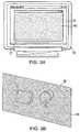
- FIG. 2Ais a view of the computer monitor of FIG. 1 displaying a video compositing application having an empty white composition window opened.
- FIG. 2Bis a perspective view of the architecture of FIG. 1 having the empty white video composition window of FIG. 2A projected thereon.
- FIG. 3Ais a view of the composition window having a black masking background applied.
- FIG. 3Bis a perspective view of the architecture of FIG. 1 having the contents of the video composition window of FIG. 3A projected thereon.
- FIG. 4Ais a view of the composition window having a blank rectangular matte and a blank circular matte inserted atop the black masking background.
- FIG. 4Bis a perspective view of the architecture of FIG. 1 having the contents of the video composition window of FIG. 4A projected thereon, wherein the projected images of the blank mattes are not aligned with the desired surfaces of the wall and experience substantial optical distortion.
- FIG. 5Ais a view of the composition window wherein the shape and position of the blank rectangular matte and the blank circular matte have been adjusted so that the projected images of the blank mattes are aligned with and overly the desired surfaces of the wall.
- FIG. 5Bis a perspective view of the architecture of FIG. 1 having the contents of the video composition window of FIG. 5A projected thereon.
- FIG. 6Ais a view of the composition window wherein striped imagery has been added to the blank rectangular matte and the blank circular matte.
- FIG. 6Bis a perspective view of the architecture of FIG. 1 having the contents of the video composition window of FIG. 6A projected thereon, wherein the striped imagery of the mattes experience substantial optical distortion.
- FIG. 7Ais a view of the composition window wherein the internal properties of the rectangular and circular mattes have been adjusted so that the projected striped imagery content is not optically distorted.
- FIG. 7Bis a perspective view of the architecture of FIG. 1 having the contents of the video composition window of FIG. 7A projected thereon.
- FIG. 8is a schematic of the image projection system of FIG. 1 wherein the laptop computer and A/D converter is replaced with a DVD player.
- FIG. 9is a flowchart of an image mapping and projection method according to an embodiment of the present invention.
- FIG. 10is a schematic of an image projection kit according to an embodiment of the present invention.
- FIG. 11is a schematic of an image projection system utilizing the image projection kit of FIG. 10 according to an embodiment of the present invention.
- FIG. 12is an illustration of the an image projection system of FIG. 11 installed at a user's site according to an embodiment of the present invention.
- FIG. 13Ais an illustration of the computer of the image projection system displaying a video compositing application in projector installation mode.
- FIG. 13Bis an illustration of the user's site wherein the content of the video compositing application of FIG. 13A is projected on the architecture.
- FIG. 14Ais an illustration of the computer of the image projection system wherein the video imaging system is in image capture mode, thereby generating a picture of the architecture of the user's site on the video compositing application.
- FIG. 14Bis an illustration of the user's site when the image projection system is in the image capture mode.
- FIG. 15Ais an illustration of the computer of the image projection system wherein the video imaging system is in the matte layout portion of a mapping mode, and wherein blank mattes have been inserted atop the captured image of the architecture.
- FIG. 15Bis an illustration of the user's site having the contents of the video compositing application of FIG. 15A projected onto the architecture, wherein the projected images of the blank mattes are not aligned with the desired surfaces of the architecture.
- FIG. 16Ais an illustration of the computer of the image projection system wherein the video imaging system is in the corner pin portion of the mapping mode, and wherein the shape and position of the blank mattes have been adjusted so that the projected images of the blank mattes are aligned with and overly the desired surfaces of the architecture.
- FIG. 16Bis an illustration of the user's site having the contents of the video compositing application of FIG. 16A projected onto the architecture, wherein the projected images of the blank mattes correspond with the desired surfaces of the architecture.
- FIG. 17Ais an illustration of the computer of the image projection system wherein the video imaging system is in a content composition mode, wherein imagery content has been inserted into the blank mattes and corrected for optical distortion.
- FIG. 17Bis an illustration of the user's site having the contents of the video compositing application of FIG. 17A projected onto the architecture, wherein the mattes and the associated imagery content are projected on the architecture in a video loop.
- FIG. 18is a schematic of a system for distributing and/or displaying video projection clips over a wide area network.
- FIG. 19is a schematic of an alternative embodiment of an image projection kit wherein the control unit is omitted according to the present invention.
- FIG. 20is a schematic of a system for distributing and/or displaying video projection clips over a wide area network according to an alternate embodiment of the present inventions.
- FIG. 1illustrates an image projection system 100 according to an embodiment of the present invention.
- the image projection system 100In addition to being able to project different visual elements (i.e., imagery content) onto objects/architectures, the image projection system 100 also has the capabilities to map the surfaces of the such three-dimensional architectures. As will be described in detail below, the image projection system 100 can project imagery content onto a plurality of non-coplanar and non-adjacent surfaces of an architecture without the imagery content experiencing optical distortion.
- the term architectureis not limited to building structures but includes, without limitation, any surface, combination of surfaces, objects, sculptures, or the like.
- the image projection system 100can be used to project all kinds of imagery content, including, without limitation, still photographs, video clips, still digital images, streaming digital video, movies, or any other visual content.
- video clips that have no camera movementwhich lends itself to the illusion
- ambient imagesbasically a moving photograph
- “loopable” clipsin point and out point matched
- “floaters”clips shot in front of a black backdrop
- imagery contentcan be projected onto different surfaces of the architecture as a plurality of separate images or as a coordinated single image.
- the image projection system 100can be modified to simultaneously generate audio that corresponds to the imagery content being displayed.
- the addition of audiocan enhance an observer's sensory experience and/or make the projected illusion more believable. This can be done by adding a separated stereo system, by coupling speakers to the laptop computer 10 , or by activating speakers built into the laptop computer 10 .
- the image projection system 100comprises a laptop computer 10 , an analog/digital (“A/D”) converter 10 , and a video projector 30 . While a laptop computer 10 is illustrated, any other type of computer or processing unit can be used that is capable of performing the functions described throughout this application. The exact processing capabilities, memory needs, and hardware requirements of the laptop computer will be dictated on a case-by-case basis, taking into consideration such factors as the complexity of the architecture being mapped and the complexity of the imagery content to be projected.
- the laptop computer 10is operably connected to the A/D converter 20 via a connector cable 11 , such as a firewire, a DSL cable, a fiberoptic line, an s-video cable, or the like.
- a connector cable 11such as a firewire, a DSL cable, a fiberoptic line, an s-video cable, or the like.
- a high speed data transmission lineis used.
- Utilizing a high speed port, such as a firewire portmakes it possible to transmit data to the projector 30 from the laptop computer 10 , and project the corresponding imagery onto the architecture in real time.
- the A/D converter 20is in turn operably connected to the projector via a connector cable 21 , such as an s-video cable or the like.
- a connector cable 21such as an s-video cable or the like.
- the inventionis not, however, limited to any specific type of connection cable so long as the components of the system 100 can operably communicate with one another and/or transmit data therebetween.
- any and/or all operable connectionscan be wireless, utilizing radio frequency (“RF”) signals, infra-red (“IR”) signals, or the like.
- RFradio frequency
- IRinfra-red
- any digital video (“DV”) devicemay be used.
- DVdigital video
- the mini-DV digital cameracan create an accurate registration of the video mapping, and implementation thereof, such that the camera keeps the video aspect ratio and alignment proper and calibrated. While utilizing a DV device that allows real time conversion of data transmitted to the video projector 30 from the laptop computer 10 is preferred, the invention is not so limited.
- the laptop computer 10has a video compositing software application or a similar program loaded thereon.
- a video compositing applicationsuitable for use with the present invention is Adobe® After Effects®.
- the video compositing applicationallows a user to see in real-time to a video source.
- the video compositing applicationallows a user to essentially see on the display screen 12 of the laptop computer 10 (and control in real time) what is being projected onto the surfaces of the architecture 50 itself. This is exemplified in FIGS. 2A-7B .
- the image projection system 100enables a user to utilize a single projector 30 to cast imagery content on multiple surfaces of the three-dimensional architecture 50 , such as the surfaces 51 - 53 .
- the image projection system 100compensates for distortions when projecting onto the non-coplanar and/or non-adjacent surfaces within the three-dimensional architecture 50 , integrating architecture, light, and darkness into an immersive environment.
- FIG. 9a flowchart of a method for mapping the architecture of the architecture 50 , and for projecting imagery content onto the architecture 50 based on the map created, is illustrated according to an embodiment of the present invention.
- inventive method of FIG. 9will be described below in relation to the image projection system 100 of FIG. 1 , the various interfaces shown in FIGS. 2A-7A , and the image projection system 800 of FIG. 8 .
- the method of the present inventionis not limited to any specific system, hardware, software, or arrangement of components.
- the user of the image projection system 100evaluates the architecture 50 and identifies the surfaces of the architecture 50 that are to be projected on, thereby completing step 910 of FIG. 9 .
- the surfaces 51 and 52are non-coplanar and non-adjacent to one another.
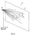
- the userthen identifies a location 31 at the work site from which a line-of-sight exists to at least one of the surfaces 51 , 52 , completing step 915 of FIG. 9 .
- a locationbe identified from which a line-of-sight exists to all of the surfaces 51 , 52 on which imagery content is to be projected.
- additional projectorscan be utilized. In such embodiments, the mapping and projection processes discussed herein will be performed for all of the projectors, and the projection of the imagery content by the different projectors will be coordinated.
- the video projector 30is secured at the location 31 .
- the video projector 30is secured at the location 31 in a fixed orientation that affords the video projector 30 the ability to project imagery content onto the surfaces 51 , 52 , thereby completing step 920 of FIG. 9 .
- This “locking-down” of the projector device 30is performed prior to any video or other image content being rendered.
- the video projection/presentationis utilized after all the video is produced.
- the video projector 31is preferably “locked-down” in place before the video production begins. As discussed below, it is through the “locked-down” position that the mapping process occurs.
- the video projector 30can be secured at the location 31 via any means possible, including bolting, brackets, clamping, screwing, nailing, gluing, magnetism, etc.
- the video projector 30can be secured so as to be easily removable from the location 31 or it can be fixedly attached thereto.
- the projector device 30is operably connected to the laptop computer 10 as described above, thereby completing step 925 of FIG. 9 .
- the laptop computer 10has a video post-production compositing program loaded thereon, which in this embodiment is Adobe® After Effects®.
- the useractivates/opens the Adobe® After Effects® application 15 on the laptop computer 10 .
- All user commands on the laptop computer 10are inputted via traditional input means, such as a mouse, keyboard, etc
- All of Adobe After Effects' software applications, tools, and controlsare performed by selecting and executing the proper commands within the various interfaces, toolbars, menus, icons, etc of the Adobe® After Effects® application.
- software applicationsthat are equivalent to Adobe® After Effects® can be used, and that such applications will often refer to functions and interfaces that are equivalent to those described herein by different names.
- the useropens a composition window 16 .
- the laptop computer 10is operably coupled to the video projector 30 .
- activating a “line video preview” commandwill project the contents of the composition window 16 onto the architecture 50 in real time (as shown in FIG. 2B ).
- changing the content of the composition window 16will result in corresponding changes to the imagery being projected onto the architecture 50 .
- the composition window 16is empty and white.
- the white composition window 16is projected onto the architecture 50 as a white rectangular area 18 , as illustrated in FIG. 2B .
- the white rectangular area 18covers the rectangular surface 51 , the circular surface 52 , and a portion of the flat surface 53 .
- the surfaces (or portions thereof) of the architecture 50 that are not being projected ontoare shaded gray throughout this application. If desired, and if necessary to capture all of the desired surfaces of the architecture 50 , the size of the white rectangular area 18 can be increased by increasing the distance between the architecture 50 and the video projector 30 .
- a black masking background layer 17is applied to the composition window 16 .
- the application of the black masking background layer 17creates the illusion of an absent video projector/feed. In other words, the negative space is projected as black and it appears as though there is no projection onto the architecture 50 , as exemplified in FIG. 3B .
- a blank rectangular matte 22 and a blank circular matte 23are inserted into the composition window 16 atop the black masking background layer 17 , thereby completing step 935 of FIG. 9 .
- the usermay insert these mattes 22 , 23 into the composition window 16 through a video projection function, or similar function of the software application.
- the shape, size, and position of the blank mattes 22 , 23 in the composition window 16are roughly approximated to correspond to the shape, size, and location of the surfaces of the architecture 50 on which it is desired to project imagery content.
- the desired surfaces of the architecture 50are the rectangular surface 51 and the circular surface 52 respectively.
- images of the blank mattes 22 , 23are projected onto the architecture 50 as images 22 A, 23 A respectively in real time.
- the projection angle of the projector device 30is not normal to the display surfaces 52 , 51 , and because the blank mattes 22 , 23 are not properly positioned within the composition window 16 , the projected images 22 A, 23 A experience substantial optical distortion.
- the userthen begins to adjust the size, shape, position, orientation, or any combination thereof of the blank mattes 22 , 23 within the composition window 16 so that the projected images 22 A, 23 A are aligned with and overly the display surfaces 51 , 52 respectively.
- Thisis done by the user adjusting the edges of the mattes 22 , 23 within the composition window 16 and visually observing the real time effect that such adjustments have on the location and orientation of the edges of the projected images 22 A, 23 A on the architecture 50 .
- This processis continued until all of the edges of the projected images 22 A, 23 A coincide with the edges of the display surfaces 51 , 52 of the architecture 50 , thus completing step 940 of FIG. 9 .
- edges of the projected images 22 A, 23 Aare invisible to a viewer and it appears as if the projected images 22 A, 23 A perfectly conform to the display surfaces 51 , 52 .
- software toolssuch as rotating, scaling, corner pinning, skewing, positioning, or any combination thereof can be used. This procedure is performed for all surfaces of the architecture 50 that are to be projected onto. As necessary, additional blank mattes can be added to the composition window 16 and sized accordingly.
- imagery contentis inserted into the mattes 22 , 23 .
- equally spaced horizontal stripeshave been added to the mattes 22 , 23 .
- the imagery contentcan include, without limitation, still photographs, video clips, still digital images, streaming digital video, movies, or any other visual content.
- the projection angle of the projection device 30is not normal to the non-coplanar and non-adjacent display surfaces 51 , 52 , the projection of the imagery content on the display surfaces 51 , 52 experiences substantial optical distortion (visible in FIG. 6B ). While the projection of the imagery content is visibly distorted, it should be noted that the imagery content is still properly aligned with and overlays the display surfaces 51 , 52 . This is because the projection of the imagery content is limited to the space within the projected images 22 A, 23 A of the mattes 22 , 23 , which were sized and oriented in the steps described above.
- the optical distortion of the projected imagery content on the display surfaces 51 , 52can be detected by visual inspection. For example, it can be seen that the stripes projected onto the rectangular surface 51 are not of equal width and are not spaced apart equally. Similarly, the stripes projected onto the circular surface 52 are not equally spaces and are diverging. This “skewing” is the result of the display surfaces 51 , 52 being angled with respect to the video projection line. In some instances, the optical distortion of the projected imagery content may be visually detected by viewing the architecture 50 as a whole, and evaluating the continuity of the projected imagery content as it appears on the various surfaces 51 - 53 of the architecture 50 .
- the useradjusts the internal properties of the mattes 22 , 23 to compensate for the optical distortion. This is done by using tools within the video compositing application, including, without limitation, rotating, scaling, corner pinning, general positioning, skewing, or any combination thereof. Adjusting the internal properties of the mattes 22 , 23 results in a corresponding change in how the imagery content is projected onto the display surfaces 51 , 52 in real time. As mentioned above, this is made possible by using the live video preview function of the video compositing application. Such correction would be especially effective when utilizing text imagery in the projections.
- the general layout of the composition window 16i.e. the map
- the matte coordinates and the internal properties of each mattecan then be saved for future use.
- the usercan then utilize the saved map in the future to insert any piece of imagery content and/or change the imagery content as desired.
- the usercan easily change the imagery content to be projected onto the architecture 50 without having to go through the mapping procedure by simply inserting new imagery content into the mattes.
- the internal matte propertieswill automatically be applied to the new imagery content.
- a loopis designed and rendered within the video compositing application to effectuate continuous play of the imagery content.
- the content of the composition window 16including the looped imagery content, is compressed, e.g., in a mpeg-2 format, and then burned onto a DVD, thereby completing step 950 of FIG. 9 .
- the laptop 10 and A/V converter 20are then disconnected, and a DVD player 40 is operably connected to the video projector 30 , completing step 955 of FIG. 9 .
- the DVD on which the video clip was savedis then inserted into the DVD player 40 and played.
- the imagery content of the composition window 16is retrieved from the DVD and projected onto the architecture 50 in a looped fashion via the video projector 30 , completing step 960 .
- a DVD player 40is illustrated as the video playback device, the invention is not so limited.
- Other electronic devicescan be used to playback the stored imagery content of the composition window, including for example, solid state playback devices, personal computers, or the like.
- the storage of the video clipis not limited to a DVD) but can be stored on any memory medium, including hard disks, zip drives, USB storage devices, etc.
- a useris capable of incorporating the previous application of the masking process into the metal surfaces or cells (i.e., discernible portions of walls, ceiling, floors and general surfaces).
- masking, or use of blackis the major effect needed, e.g., the user does not want to project on the mirrors or elements other than specific surfaces such as metal surfaces, white surfaces, etc.
- a userwould then utilize a video compositing application or a similar program to create video maps that were black and white, black where there is to be no imagery and white where there is to be video and imagery.
- the present inventioncan compensate for multiple instances of distortion on multiple non-coplanar and non-contiguous surfaces within a three-dimensional area.
- the present inventioncan create a masking effect, which creates the illusion of blackness on surfaces upon which the user does not want to project video and images or on areas with no surfaces to project upon,
- FIG. 10-17generally, an image projection kit will be discussed and described in detail according to exemplary embodiments of the present invention. However, it is to be understood that the concepts discussed above can be incorporated therein as necessary and/or desired.
- the image projection kit 200generally comprises a projector mounting mechanism 210 , a projector apparatus 220 , a control unit 230 , data transmission and power cables 240 and video compositing software 250 .
- the image projection kit 200is designed to be sold as an a integrated retail product kit with all components housed in a single box at the point of purchase. Of course, one or more of the components could be replaced, combined and/or omitted if desired.
- the projector mounting mechanism 210is provided to facilitate mounting of the projector apparatus 220 to a desired surface and/or structure at a user's site, such as an apartment, home, condominium, outdoor area, etc.
- the mounting mechanism 210generally comprises four members 212 and a plate 211 to which the projector apparatus 220 can be fastened, for example by bolts, screws, clamps, adhesives, hook-and-loop tape, double-sided tape, slide-fit assemblies, snap-fit assemblies, etc.
- the members 212comprise holes near their bottoms to facilitate rigid connection to the desired surface and/or structure at the user's site via screws, bolts or other fasteners.
- the members 212could incorporate other connection mechanisms, such as flanges, clamps, adhesives, hook-and-loop tape, double-sided tape, slide-fit assemblies, snap-fit assemblies, etc. If desired, the member 212 could be merely adapted to rest atop a surface.
- the plate 211is pivotally mounted to the members 212 so that the projector apparatus 220 can be swiveled to the desired orientation even when the member 212 are rigidly secured in place.
- the projector mounting mechanism 210also preferably comprises a locking mechanism 213 (generically illustrated).
- the locking mechanism 213can be activated to secure the projector apparatus 220 in a fixed orientation so as to prohibit unwanted movement once the projector apparatus 220 is properly oriented and mounted by the mounting mechanism 210 .
- the locking mechanism 213can take on a wide variety of structural arrangements, including interlocking flanges, a slide-bar assembly, tangs, compression assemblies, frictional engagement, etc.
- mounting mechanism 210is illustrated as a separate structure than the projector apparatus 220 , it is to be understood that the components could be combined so that the mounting mechanism 210 and the projector apparatus 220 are an integral or fastened together component.
- the projector mounting mechanism 210is illustrated as being a “quadpod” style structure for, merely exemplary purposes. It is to be understood that the mounting mechanism 210 can take on a wide variety of structural arrangements. For example, the mounting mechanism 210 could be merely a flange or any other combination of beams and/or plates.
- the projector apparatus 220is a device that has both image projection and image capture capabilities, both of which are facilitated from the same point of view, which in this case is through lens 221 .
- the projector apparatus 220comprises a housing 222 , a lens 221 , and a communication port 223 for receiving and/or sending data signals. The structure and operation of the projector apparatus 220 will be discussed in greater detail below with respect to FIG. 11 .
- the control unit 230is a preferably stand-alone component that acts as the head unit for the image projection kit 200 .
- the functions and structure of the control unit 230can be integrated into the projector apparatus 220 and/or the user's computer as hardware and/or software.
- the control unit 230comprises a housing 231 , a transceiver 232 , and a plurality of data ports and/or memory slots 233 .
- the control unit 230preferably supports the following functionality: (i) wireless/tethered video signal connectivity to the projector apparatus 220 ; (ii) wireless/tethered serial control of the projector apparatus 220 (e.g., On/off, diagnostics, etc.); (iii) wireless/tethered online/network capabilities; (iv) memory expansion; (iv) enhanced video processing capabilities (i.e., the control unit 230 preferably does all the “heavy lifting” when it comes to processing and compiling the video compositions); (v) built in custom software for mapping and playback; and (vi) control over built in image capture sub-system of the projector apparatus 220 .
- the necessary cables 240are also included with the image projection kit 200 .
- the cables 240can include the power cables and data communication cables necessary to connect the components of the system 200 . Examples of such cables include without limitation, firewires, USB cables, mini-USB cables, HDMI cables, fiber-optic cables, etc. Of course, if desired, all data communication can be achieved through wireless means such as RF, IR, etc.
- the image projection kit 200comprises a software package 250 .
- the software packageis a video compositing software application.
- a video compositing application suitable for use with the present inventionis Adobe® After Effects®.
- a customized software packageis used that can achieve the functions and render the interfaces described throughout the present patent application.
- the software package 250can be included in the kit 200 on a computer readable medium, such as a flash drive, CD-ROM, or other external memory source.
- the software package 250can be included in the kit 200 as an alphanumeric, numeric, alphabetic or other code that allows users to access and download the software onto their computers from a wide area network (“WAN”), such as the Internet.
- WANwide area network
- the software package 250may even be supplied free of charge to users to promote the kit 200 .
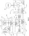
- the housing 222 of the projector apparatus 220contains all of the necessary electrical, mechanical and circuitry components so that the projector apparatus 220 has both image projection, image capture and data transmission and reception capabilities.
- the projector apparatus 220comprises a projector sub-system 225 , an image sensor sub-system 226 , a single lens reflex assembly (which comprises the lens 221 and a pivotable mirror 227 ), a processor 224 (“CPU”) and a plurality of signal/data ports 223 . All of the components are operably and communicably connected to one another via a bus or other means.
- the projector sub-system 225comprises all of the circuitry and mechanical components necessary to project imagery content, such as videos or still content, onto the desired real-world architecture of a user's site, such as a wall, post, ceiling or floors.
- imagery contentsuch as videos or still content
- the image sensor sub-system 226comprises all of the circuitry and mechanical components necessary to sense and transmit a real-world image perceived by the lens 221 as data for recreation on a display device 305 of a the computer 300 .
- a detailed explanation of the image sensor sub-system 226is not necessary as such systems are well known in the art and are commonly used in digital cameras. It should also be appreciated that in some embodiments of the invention, portions of the image sensor sub-system 226 and the projector sub-system 225 can be combined to minimize circuitry and size of the overall device.
- the projector apparatus 220can switch between an image projection mode and an image capture mode by manipulation of the pivotable mirror 227 .
- the image sensor sub-system 226When in the image capture mode, the image sensor sub-system 226 is active and the projector sub-system 225 is inactive.
- the image sensor sub-system 226is inactive and the projector sub-system 225 is active.
- the CPU 224when the CPU 224 receives an image sensor activation signal from the control unit 230 (or computer 300 ) via the data port 223 , the CPU 224 rotates the mirror 227 (if necessary) so that it is at the illustrated 45 degree angle. As a result, the image sensor sub-system 226 is in operable optical alignment with the lens 221 and can thereby perceive the real world image seen by the lens 221 . At this time, the projector sub-system 225 is blocked by the back surface of the mirror 227 and is preferably turned off.
- the CPU 224when the CPU 224 receives a projection activation signal from the control unit 230 (or computer 300 ) via the data port 223 , the CPU 224 rotates the mirror 227 (if necessary) 45 degrees downward so that the mirror 227 does not obstruct the line of sight from the lens 221 to the projector sub-system 225 .
- the projector sub-system 225is in operable optical alignment with and can project imagery through the lens 221 .
- the image sensor sub-system 226is blocked by the mirror 227 and is preferably turned off.
- the projector apparatus 220can both capture an image of the desired architecture on the computer for mapping and later project images onto this architecture from the same point of view.
- the control unit 230comprises a processor 234 (“CPU”), a transceiver 232 , an internal memory 235 , an interface port 236 , and a data port 233 . All of these components are in operable and communicable cooperation with one another inside of the housing 231 .
- the control unit 230communicates with the projector apparatus 220 via the transceiver 232 and with the user's computer 300 via the data port 233 .
- a single or multiple wired or wireless portscan be used for all data communication between the projector apparatus 220 , the control unit 230 and/or the computer 300 . Any kind of data communication port can be used, including HDMI, IR, RF, USB, mini-USB, firewire, etc.
- the CPU 234is a properly programmed processor capable of performing the necessary functions described herein and above as functions (i)-(vi).
- the interface port 236operably receives an external memory device 260 , which can be used to store the mapping and imagery content information created by the user on the computer 300 using the software 250 . This data is retrieved from the external memory device 260 , processed by the CPU 234 and transmitted to the projector apparatus 220 for appropriate handling.
- the control unit 230can have an internal memory 235 for storing mapping and imagery content information created by the user on the computer 300 using the software 250 . In this embodiment, the computer 300 can transfer this data to the control unit 230 for storage on the internal memory 235 via communication between the respective ports 233 and 303 .
- the software 250is loaded onto the computer 300 and executed by the user as described below to create the mapping and imagery content data that is transferred to the control unit 230 (and eventually projected by the projector apparatus 220 ).
- the computerstored the software 250 in its internal memory and the user uses the associated interfaces and data files of the video compositing application.
- the computer 300can be connected to the Internet 400 to connect to a video content provider in order to purchase and download video projection clips (i.e., video data files) for projection on their architecture.
- FIGS. 12-17Bthe installation and operation of the image projection kit 200 at an end user's site will be described more fully. It is to be understood that the mapping and setup techniques discussed above in relation to FIG. 1-9 can be implemented in addition to or instead of the below technique. It is also to be understood that the exact sequence of the installation and setup process discussed below are not limiting of the invention and can be done in any order.
- the useridentifies the architecture 700 on which he/she wants to project imagery content, such as videos, still imagery, photographs, etc.
- the selected architecture 700is a three dimensional architecture consisting of three non-coplanar wall surfaces 701 - 703 .
- the projector apparatus 220is pivotally connected to the mounting mechanism 210 and the combined assembly is then rigidly secured to a desired support structure 705 that affords a line of sight to the surfaces 701 - 703 of the architecture 700 .
- the projector apparatus 220can still pivot and/or translate relative to the base portion of the mounting mechanism 210 so that the orientation of the projector apparatus 220 can be adjusted.
- the software 250is then loaded onto the computer 300 , which in this embodiment is a laptop computer.
- a computercan be any electronic device (or combination of devices) having a display and the processing capabilities necessary to execute the software 250 and performing the necessary data communication, transfer and/or storage.
- the computer 300can be a television, a set-top cable box, a video game system, the control unit 200 and/or combinations thereof.
- the software 250can be loaded onto the computer 300 via a computer readable medium or downloading through a WAN. All of the necessary power and data communication cables 240 are then installed so that the computer 300 , the control unit 230 and the projector apparatus 250 are powered and communicate with one another, as established in FIG. 11 . Of course, (or wireless communication paths can be utilized as necessary.
- the usersets the control unit 230 to a setup mode. This can be done by having a manual switch on the control unit or can be done through the software 250 (i.e., the video compositing software) installed on the computer 300 .
- the userlaunches the software 250 on the computer via conventional techniques.
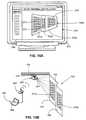
- the userthen enters/launches a setup/projector installation interface 251 through the appropriate menu.
- the window of the setup/projector installation interface 251is filled with an aiming pattern 252 .
- the computer 300communicates and controls the projector apparatus 220 (via the head unit 230 ) so that the projector apparatus 220 is switched into projection mode (i.e., the projector sub-system 225 is activated) and an image of the aiming pattern 252 A is projected by the projector apparatus 220 through its lens 221 .
- the orientation of the projector apparatus 220is then manipulated (i.e., pivoted and/or translated) by the user until the image of the aiming pattern 252 A covers the desired architecture 700 (or the desired portions thereof).
- Manipulation of the orientation of the projector apparatus 220can be manually achieved or remotely achieved through the remote control of built-in servomotors.
- the locking mechanism 213 ( FIG. 10 ) of the mounting mechanism 210is activated, thereby locking the projector apparatus 220 in a fixed orientation, thereby prohibiting unwanted movement.
- the userthen proceeds to the next step of setup by activating a setup/mapping/capture interface 253 A.
- the projector apparatus 220is instructed to switch to an image capture mode (i.e., the image sensor sub-system 226 is activated by manipulation of the minor 227 and the projector sub-system 225 is deactivated).
- the projector apparatus 220captures and transmits an image of the architecture 700 A (as seen through the lens 221 ) to the computer 300 for display within the setup/mapping/capture interface 253 .
- the image of the architecture 700 Acan then be permanently or temporarily saved on the computer 300 .
- the userthen proceeds to the next step which is to activate the mapping portion of the software by entering a setup/mapping/matte layout interface 254 .
- this interface 254is activated, the projector apparatus 220 is instructed to switch back to projection mode (i.e., the projector sub-system 225 is activated by manipulation of the mirror 227 and the image sensor sub-system 226 is deactivated).
- the image of the architecture 700 Aremains visible in the interface 254 as an underlying “layer” upon which the user can then create (and/or insert) blank mattes 271 - 273 atop.
- the “layer” with the mattes 271 - 273is projected by the projector apparatus 220 onto the real world architecture 700 , thereby projecting images of the mattes 271 A- 273 A onto the real world architecture 700 .
- the useradds the appropriate number of the mattes 271 - 273 necessary (and/or desired) to cover the surfaces 701 - 703 of the architecture.
- a single matteis added for each different real world surface of the architecture so that optical distortion can be remedied later.
- the inventionis not so limited and multiple mattes can be used for a single real world surface and/or a single matte can be used for multiple real world surfaces.
- one or more of the mattes 217 - 273are generally positioned within the interface 254 , the user then begins to adjust the size, shape, position, orientation, or any combination thereof of the blank mattes 271 - 273 within the interface 254 so that the edges of the blank mattes 271 - 273 are respectively aligned with and coincide with the edges of the images of the surfaces 701 A- 703 A within the interface 254 .
- the underlying “layer” of the image of the architecture 700 Acan be traced to create the blank mattes 271 - 273 .
- software toolssuch as rotating, scaling, corner pinning, skewing, positioning, or any combination thereof can be used.
- the projected images of the mattes 271 A- 273 Acorrespond to the real world surfaces 701 - 703 so that all of the edges of the projected images of the mattes 271 A- 273 A coincide with the edges of the display surfaces 701 - 703 of the architecture 700 .
- the edges of the projected matte images 271 A- 273 Aare invisible to a viewer and it appears as if the projected matte images 271 A- 273 A perfectly conform to the display surfaces 701 - 703 respectively.
- the usercan further fine tune the size, shape, position, orientation, or any combination thereof of the blank mattes 271 - 273 using real-world observation and comparative technique discussed above. Furthermore, once done creating mattes, the user can also use a corner pinning type tool to make sure that the optical distortion (if any) is compensated for.
- the userenters a content composition interface 255 to select what imagery content he/she wants to project on the architecture 700 .
- the userselects the desired imagery content file from a content library 256 .
- the content library 256is a file folder-based organization system containing all of the user's imagery content files that can be inserted into the mattes 271 - 273 and thus projected onto the architecture.
- the imagery content filescan be any suitable data format for rendering still images or videos.
- the present inventionalso provides a new way by which a use can build his/her image projection content library.
- the userassociates the selected imagery content file with the desired matte 271 - 273 .
- Thiscan be done in any suitable way, such as a drag-and-drop technique or traditional command association.
- imagery contentis exemplified as simple static symbols, the invention is not so limited.
- the imagery contentcan include, without limitation, still photographs, video clips, still digital images, streaming digital video, movies, or any other visual content.
- the projection angle of the projector apparatus 220is not normal to the non-coplanar and non-adjacent display surfaces 701 - 703 , the projection of the imagery content on the display surfaces 701 - 703 will experiences substantial optical distortion if not connected. Wile the projection of the imagery content would be visibly distorted, it should be noted that the imagery content would still be properly aligned with and overlays the display surfaces 701 - 703 . This is because the projection of the imagery content is limited to the space within the projected images of the mattes 271 A- 273 A, which were sized and oriented in the steps described above.
- the optical distortion of the projected imagery content 281 A- 283 A on the display surfaces 701 - 703can be fixed by the user adjusting the internal properties of the mattes 271 - 273 to compensate for the optical distortion. This is done by using tools within the video compositing application, including, without limitation, rotating, scaling, corner pinning, general positioning, skewing, or any combination thereof. Adjusting the internal properties of the mattes results in a corresponding change in how the imagery content is projected onto the display surfaces in real time. As mentioned above, this is made possible by using the live video preview function of the video compositing application. Such correction would be especially effective when utilizing text imagery in the projections.
- the general layout of the interface 255i.e. the map
- the matte coordinates and the internal properties of each mattecan then be saved either internally or on an external memory device.
- the usercan then utilize the saved map in the future to insert any piece of imagery content and/or change the imagery content as desired.
- the usercan easily change the imagery content to be projected onto the architecture 700 without having to go through the mapping procedure by simply inserting new imagery content into the mattes.
- the internal matte propertieswill automatically be applied to the new imagery content.
- a loopis designed and rendered within the video compositing application to effectuate continuous play of the imagery content.
- This dataincluding the looped imagery content, is compressed, e.g., in a mpeg-2 format, and then transmitted to the control unit 230 for internal storage.
- the control unitcan store the data either internally or read it from an external memory device (see FIG. 11 ).
- control unit 230Once the control unit 230 has the necessary data, the control unit is switched to a display mode wherein the data (including the map and associated imagery content) is retrieved and projected onto the architecture 700 in a looped fashion via the projector apparatus 220 .
- the userOnce the user has created a composition and is ready to create their own customized loop or “mix” they than tell the program to compile or render and the CPU in the head unit compiles and flattens the mix into a single playable file. Once this file is compiled, it is playable via a playlist/playback application that the user can control from their laptop/phone/remote etc. The user than switches the head unit to playback mode and uses this for playback
- the content distribution system 1000comprises a front end portion 1100 , a WAN portion 1200 , and a back end portion 1300 .
- the front end portion 1100is an end user's site that comprises the image projection kit 200 installed as described above.
- the content distribution system 1000provides a new and non-obvious way of providing users with projection clips (i.e., video imagery content) for their content libraries for projection onto their real world architecture 700 .
- a user using the image projection kit 200 as described abovewill want to change their imagery content often, for example, depending on the event at the user site and/or the time of year.
- the usercan build a very large library of projection clips and other imagery files for projection.
- the user's computer 300is connected to a WAN, such as Internet 400 , which is in turn connected to a large number of end computers 301 - 303 .
- a content server 1310is provided that stores a large number of content files (e.g., projection clips) that are created either in a studio 1320 or uploaded and stored on the server 1310 by other users via their computers 301 - 303 .
- content filese.g., projection clips
- the large number of content files stored on the server 1310are made accessible, searchable, viewable and downloadable to the end user's computer 300 via a website or other electronic access point.
- the websitehas the proper interfaces and databases necessary to store and authenticate a user's information, identity and/or financial information. For example, a user may be required to enter her/his credit card information to create an account. The account will be assigned a user ID and a password. The website charges a fee for each projection clip downloaded by the user. The fee can be charged to a standing account that is set up by the user or on a single-purchase basis.
Landscapes
- Engineering & Computer Science (AREA)
- Physics & Mathematics (AREA)
- General Physics & Mathematics (AREA)
- Multimedia (AREA)
- Signal Processing (AREA)
- Theoretical Computer Science (AREA)
- Databases & Information Systems (AREA)
- Geometry (AREA)
- Business, Economics & Management (AREA)
- Projection Apparatus (AREA)
- Accounting & Taxation (AREA)
- Controls And Circuits For Display Device (AREA)
- Transforming Electric Information Into Light Information (AREA)
- Computer Security & Cryptography (AREA)
- Finance (AREA)
- Strategic Management (AREA)
- General Business, Economics & Management (AREA)
Abstract
Description
Claims (9)
Priority Applications (8)
| Application Number | Priority Date | Filing Date | Title |
|---|---|---|---|
| US12/186,335US8066384B2 (en) | 2004-08-18 | 2008-08-05 | Image projection kit and method and system of distributing image content for use with the same |
| US13/306,491US8632192B2 (en) | 2004-08-18 | 2011-11-29 | Image projection kit and method and system of distributing image content for use with the same |
| US14/159,841US9078029B2 (en) | 2004-08-18 | 2014-01-21 | Image projection kit and method and system of distributing image content for use with the same |
| US14/793,197US9560307B2 (en) | 2004-08-18 | 2015-07-07 | Image projection kit and method and system of distributing image content for use with the same |
| US15/420,529US10084998B2 (en) | 2004-08-18 | 2017-01-31 | Image projection kit and method and system of distributing image content for use with the same |
| US16/141,176US10567718B2 (en) | 2004-08-18 | 2018-09-25 | Image projection kit and method and system of distributing image content for use with the same |
| US16/792,871US10986319B2 (en) | 2004-08-18 | 2020-02-17 | Method for projecting image content |
| US17/230,012US20210235049A1 (en) | 2004-08-18 | 2021-04-14 | Method for projecting image content |
Applications Claiming Priority (3)
| Application Number | Priority Date | Filing Date | Title |
|---|---|---|---|
| US60254404P | 2004-08-18 | 2004-08-18 | |
| US11/200,906US7407297B2 (en) | 2004-08-18 | 2005-08-10 | Image projection system and method |
| US12/186,335US8066384B2 (en) | 2004-08-18 | 2008-08-05 | Image projection kit and method and system of distributing image content for use with the same |
Related Parent Applications (1)
| Application Number | Title | Priority Date | Filing Date |
|---|---|---|---|
| US11/200,906Continuation-In-PartUS7407297B2 (en) | 2004-08-18 | 2005-08-10 | Image projection system and method |
Related Child Applications (1)
| Application Number | Title | Priority Date | Filing Date |
|---|---|---|---|
| US13/306,491DivisionUS8632192B2 (en) | 2004-08-18 | 2011-11-29 | Image projection kit and method and system of distributing image content for use with the same |
Publications (2)
| Publication Number | Publication Date |
|---|---|
| US20090091711A1 US20090091711A1 (en) | 2009-04-09 |
| US8066384B2true US8066384B2 (en) | 2011-11-29 |
Family
ID=40522950
Family Applications (8)
| Application Number | Title | Priority Date | Filing Date |
|---|---|---|---|
| US12/186,335Expired - Fee RelatedUS8066384B2 (en) | 2004-08-18 | 2008-08-05 | Image projection kit and method and system of distributing image content for use with the same |
| US13/306,491Expired - LifetimeUS8632192B2 (en) | 2004-08-18 | 2011-11-29 | Image projection kit and method and system of distributing image content for use with the same |
| US14/159,841Expired - LifetimeUS9078029B2 (en) | 2004-08-18 | 2014-01-21 | Image projection kit and method and system of distributing image content for use with the same |
| US14/793,197Expired - Fee RelatedUS9560307B2 (en) | 2004-08-18 | 2015-07-07 | Image projection kit and method and system of distributing image content for use with the same |
| US15/420,529Expired - LifetimeUS10084998B2 (en) | 2004-08-18 | 2017-01-31 | Image projection kit and method and system of distributing image content for use with the same |
| US16/141,176Expired - LifetimeUS10567718B2 (en) | 2004-08-18 | 2018-09-25 | Image projection kit and method and system of distributing image content for use with the same |
| US16/792,871Expired - Fee RelatedUS10986319B2 (en) | 2004-08-18 | 2020-02-17 | Method for projecting image content |
| US17/230,012AbandonedUS20210235049A1 (en) | 2004-08-18 | 2021-04-14 | Method for projecting image content |
Family Applications After (7)
| Application Number | Title | Priority Date | Filing Date |
|---|---|---|---|
| US13/306,491Expired - LifetimeUS8632192B2 (en) | 2004-08-18 | 2011-11-29 | Image projection kit and method and system of distributing image content for use with the same |
| US14/159,841Expired - LifetimeUS9078029B2 (en) | 2004-08-18 | 2014-01-21 | Image projection kit and method and system of distributing image content for use with the same |
| US14/793,197Expired - Fee RelatedUS9560307B2 (en) | 2004-08-18 | 2015-07-07 | Image projection kit and method and system of distributing image content for use with the same |
| US15/420,529Expired - LifetimeUS10084998B2 (en) | 2004-08-18 | 2017-01-31 | Image projection kit and method and system of distributing image content for use with the same |
| US16/141,176Expired - LifetimeUS10567718B2 (en) | 2004-08-18 | 2018-09-25 | Image projection kit and method and system of distributing image content for use with the same |
| US16/792,871Expired - Fee RelatedUS10986319B2 (en) | 2004-08-18 | 2020-02-17 | Method for projecting image content |
| US17/230,012AbandonedUS20210235049A1 (en) | 2004-08-18 | 2021-04-14 | Method for projecting image content |
Country Status (1)
| Country | Link |
|---|---|
| US (8) | US8066384B2 (en) |
Cited By (3)
| Publication number | Priority date | Publication date | Assignee | Title |
|---|---|---|---|---|
| US20100309224A1 (en)* | 2004-03-31 | 2010-12-09 | Canon Kabushiki Kaisha | Image displaying method, image displaying program, and display |
| US20110316885A1 (en)* | 2010-06-23 | 2011-12-29 | Samsung Electronics Co., Ltd. | Method and apparatus for displaying image including position information |
| US20150029314A1 (en)* | 2013-07-25 | 2015-01-29 | Disney Enterprises, Inc. | Volumetric display system blending two light types to provide a new display medium |
Families Citing this family (24)
| Publication number | Priority date | Publication date | Assignee | Title |
|---|---|---|---|---|
| US8066384B2 (en) | 2004-08-18 | 2011-11-29 | Klip Collective, Inc. | Image projection kit and method and system of distributing image content for use with the same |
| US20080058011A1 (en)* | 2006-08-17 | 2008-03-06 | Wei Lin | Apparatus, System and Method for Wireless Transmission for Use in Projection Display Apparatus |
| US20090059094A1 (en)* | 2007-09-04 | 2009-03-05 | Samsung Techwin Co., Ltd. | Apparatus and method for overlaying image in video presentation system having embedded operating system |
| WO2010137496A1 (en)* | 2009-05-26 | 2010-12-02 | パナソニック電工株式会社 | Information presentation device |
| US8223196B2 (en)* | 2009-06-10 | 2012-07-17 | Disney Enterprises, Inc. | Projector systems and methods for producing digitally augmented, interactive cakes and other food products |
| WO2012142250A1 (en)* | 2011-04-12 | 2012-10-18 | Radiation Monitoring Devices, Inc. | Augumented reality system |
| US8918208B1 (en)* | 2012-02-07 | 2014-12-23 | Ryan Hickman | Projection of interactive map data |
| JP5924020B2 (en)* | 2012-02-16 | 2016-05-25 | セイコーエプソン株式会社 | Projector and projector control method |
| TWI451185B (en)* | 2012-04-17 | 2014-09-01 | Delta Electronics Inc | Projector, projecting system comprising the smae and automatic image adjusting method thereof |
| US9111484B2 (en)* | 2012-05-03 | 2015-08-18 | Semiconductor Components Industries, Llc | Electronic device for scene evaluation and image projection onto non-planar screens |
| US8978551B2 (en) | 2012-07-25 | 2015-03-17 | Nike, Inc. | Projection assisted printer alignment using remote device |
| US9254640B2 (en) | 2012-07-25 | 2016-02-09 | Nike, Inc. | Projector assisted alignment and printing |
| US9070055B2 (en) | 2012-07-25 | 2015-06-30 | Nike, Inc. | Graphic alignment for printing to an article using a first display device and a second display device |
| KR102220825B1 (en)* | 2013-09-05 | 2021-03-02 | 삼성전자주식회사 | Electronic apparatus and method for outputting a content |
| US20170223321A1 (en)* | 2014-08-01 | 2017-08-03 | Hewlett-Packard Development Company, L.P. | Projection of image onto object |
| JP2016039557A (en)* | 2014-08-08 | 2016-03-22 | 株式会社リコー | Projection apparatus, projection system, and projection method |
| WO2017163928A1 (en)* | 2016-03-24 | 2017-09-28 | ソニー株式会社 | Image processing device and method |
| IT201600086859A1 (en)* | 2016-08-24 | 2018-02-24 | Osram Gmbh | PROCEDURE FOR CHECKING THE CORRESPONDENT LIGHTING SOURCES, SYSTEM AND COMPUTER PRODUCT |
| IT201600086875A1 (en)* | 2016-08-24 | 2018-02-24 | Osram Gmbh | PROCEDURE FOR CHECKING THE CORRESPONDENT LIGHTING SOURCES, SYSTEM AND COMPUTER PRODUCT |
| JP6897191B2 (en)* | 2017-03-17 | 2021-06-30 | セイコーエプソン株式会社 | Projector and projector control method |
| CN109104596B (en)* | 2017-06-21 | 2021-02-26 | 中强光电股份有限公司 | Projection system and correction method of display image |
| US10676022B2 (en) | 2017-12-27 | 2020-06-09 | X Development Llc | Visually indicating vehicle caution regions |
| US11023729B1 (en) | 2019-11-08 | 2021-06-01 | Msg Entertainment Group, Llc | Providing visual guidance for presenting visual content in a venue |
| US12086301B2 (en) | 2022-06-01 | 2024-09-10 | Sphere Entertainment Group, Llc | System for multi-user collaboration within a virtual reality environment |
Citations (79)
| Publication number | Priority date | Publication date | Assignee | Title |
|---|---|---|---|---|
| US4981360A (en)* | 1989-05-10 | 1991-01-01 | Grumman Aerospace Corporation | Apparatus and method for projection moire mapping |
| US5161013A (en)* | 1991-04-08 | 1992-11-03 | Honeywell Inc. | Data projection system with compensation for nonplanar screen |
| US5694142A (en)* | 1993-06-21 | 1997-12-02 | General Electric Company | Interactive digital arrow (d'arrow) three-dimensional (3D) pointing |
| US5795046A (en)* | 1995-11-13 | 1998-08-18 | Daewoo Electronics, Ltd. | Method for pre-compensating an asymmetrical picture in a projection system for displaying a picture |
| US6000801A (en)* | 1997-05-02 | 1999-12-14 | General Scanning, Inc. | Multi-color laser projector for optical layup template and the like |
| US6075872A (en)* | 1997-09-04 | 2000-06-13 | Tailored Lighting Inc. | Process for illuminating artwork |
| US20020031316A1 (en) | 2000-01-13 | 2002-03-14 | Lowry Brian C. | Tiled fiber optic display apparatus |
| US20020034392A1 (en) | 2000-09-21 | 2002-03-21 | Shutterfly. Com | Apparatus, architecture and method for high-speed printing |
| US6431711B1 (en)* | 2000-12-06 | 2002-08-13 | International Business Machines Corporation | Multiple-surface display projector with interactive input capability |
| US20020113950A1 (en) | 2001-02-16 | 2002-08-22 | Paul Vlahos | Interactive teleconferencing display system |
| US20020163720A1 (en) | 2001-04-06 | 2002-11-07 | 3M Innovative Properties Company | Temporary screens and methods for displaying information |
| US20020163722A1 (en) | 2001-04-06 | 2002-11-07 | 3M Innovative Properties Company | Screens and methods for displaying information |
| US20030001939A1 (en) | 1997-06-30 | 2003-01-02 | Scofield Stuart A. | Early transparency detection routine for inkjet printing |
| US20030020667A1 (en) | 2001-05-30 | 2003-01-30 | Essig John R. | Inflatable multi-function parabolic reflector apparatus and methods of manufacture |
| US20030098957A1 (en)* | 2001-11-28 | 2003-05-29 | Haldiman Robert C. | System, method and apparatus for ambient video projection |
| US20030117639A1 (en) | 2001-12-21 | 2003-06-26 | Microsoft Corporation | Print media catalog service |
| US20030163367A1 (en) | 2001-04-06 | 2003-08-28 | 3M Innovative Properties Company | Screens and methods for displaying information |
| US20030231261A1 (en)* | 2002-06-12 | 2003-12-18 | Bassi Zorawar S. | Short throw projection system and method |
| US20040001059A1 (en) | 2002-06-17 | 2004-01-01 | Hanspeter Pfister | Rendering compressed surface reflectance fields of 3D objects |
| US6677956B2 (en)* | 2001-08-15 | 2004-01-13 | Mitsubishi Electric Research Laboratories, Inc. | Method for cross-fading intensities of multiple images of a scene for seamless reconstruction |
| US6709116B1 (en)* | 2003-03-21 | 2004-03-23 | Mitsubishi Electric Research Laboratories, Inc. | Shape-adaptive projector system |
| US6712477B2 (en)* | 2000-02-08 | 2004-03-30 | Elumens Corporation | Optical projection system including projection dome |
| US20040076313A1 (en) | 2002-10-07 | 2004-04-22 | Technion Research And Development Foundation Ltd. | Three-dimensional face recognition |
| US20040095348A1 (en) | 2002-11-19 | 2004-05-20 | Bleiweiss Avi I. | Shading language interface and method |
| US20040141157A1 (en)* | 2003-01-08 | 2004-07-22 | Gopal Ramachandran | Image projection system and method |
| US20040169827A1 (en)* | 2003-02-28 | 2004-09-02 | Mitsuo Kubo | Projection display apparatus |
| US6793350B1 (en)* | 2003-03-21 | 2004-09-21 | Mitsubishi Electric Research Laboratories, Inc. | Projecting warped images onto curved surfaces |
| US20040207566A1 (en) | 2001-05-30 | 2004-10-21 | Essig John Raymond | Modular inflatable multifunction field-deployable apparatus and methods of manufacture |
| US20040240754A1 (en) | 2001-06-29 | 2004-12-02 | Smith Melvyn Lionel | Overhead dimensioning system and method |
| US20050017967A1 (en)* | 2003-04-16 | 2005-01-27 | Massachusetts Institute Of Technology | Three dimensional tangible interface for interacting with spatial-temporal data using a laser scanner |
| US20050068537A1 (en) | 2002-07-17 | 2005-03-31 | New York University | Method and apparatus for determining a bidirectional reflectance distribution function of a subject |
| US20050081161A1 (en) | 2003-10-10 | 2005-04-14 | Macinnes Cathryn | Three-dimensional interior design system |
| US20050122536A1 (en) | 2003-12-09 | 2005-06-09 | Selan Jeremy A. | Color-matched digital playback |
| US20050128751A1 (en) | 2003-05-05 | 2005-06-16 | Color Kinetics, Incorporated | Lighting methods and systems |
| US20050174473A1 (en) | 1999-11-18 | 2005-08-11 | Color Kinetics, Inc. | Photography methods and systems |
| US20050243085A1 (en)* | 2004-05-03 | 2005-11-03 | Microsoft Corporation | Model 3D construction application program interface |
| US20050276441A1 (en) | 2004-06-12 | 2005-12-15 | University Of Southern California | Performance relighting and reflectance transformation with time-multiplexed illumination |
| US20050285860A1 (en) | 2004-06-18 | 2005-12-29 | Hanspeter Pfister | Scene reflectance functions under natural illumination |
| US20060001839A1 (en) | 2004-07-01 | 2006-01-05 | Beardsley Paul A | Projector-camera system with laser pointers |
| US20060002110A1 (en) | 2004-03-15 | 2006-01-05 | Color Kinetics Incorporated | Methods and systems for providing lighting systems |
| US20060022214A1 (en) | 2004-07-08 | 2006-02-02 | Color Kinetics, Incorporated | LED package methods and systems |
| US20060028400A1 (en) | 2004-08-03 | 2006-02-09 | Silverbrook Research Pty Ltd | Head mounted display with wave front modulator |
| US20060033674A1 (en) | 2002-05-30 | 2006-02-16 | Essig John R Jr | Multi-function field-deployable resource harnessing apparatus and methods of manufacture |
| US20060038814A1 (en) | 2004-08-18 | 2006-02-23 | Ricardo Rivera | Image projection system and method |
| US20060146047A1 (en) | 2003-07-16 | 2006-07-06 | Marion Dale S | Three dimensional display method, system and apparatus |
| US20060250503A1 (en) | 2002-05-16 | 2006-11-09 | Crutchfield Corporation | System and method of image capture simulation |
| US20060263758A1 (en) | 2005-05-06 | 2006-11-23 | Crutchfield Corporation | System and method of image display simulation |
| US20060291851A1 (en) | 2005-02-08 | 2006-12-28 | Nikon Corporation | Digital camera with projector and digital camera system |
| US20070024756A1 (en) | 2005-07-29 | 2007-02-01 | Wojciech Matusik | System and method for defocus difference matting |
| US20070025727A1 (en) | 2005-07-29 | 2007-02-01 | Wojciech Matusik | Fast switching camera aperture |
| US7182465B2 (en)* | 2004-02-25 | 2007-02-27 | The University Of North Carolina | Methods, systems, and computer program products for imperceptibly embedding structured light patterns in projected color images for display on planar and non-planar surfaces |
| US20070063981A1 (en) | 2005-09-16 | 2007-03-22 | Galyean Tinsley A Iii | System and method for providing an interactive interface |
| US20070133034A1 (en) | 2005-12-14 | 2007-06-14 | Google Inc. | Detecting and rejecting annoying documents |
| US20070164955A1 (en) | 2006-01-19 | 2007-07-19 | Sanyo Epson Imaging Devices Corporation | Liquid crystal display device and head-up display using it |
| US20070216905A1 (en) | 2002-09-25 | 2007-09-20 | New York University | Method and apparatus for determining reflectance data of a subject |
| US20070279412A1 (en) | 2006-06-01 | 2007-12-06 | Colin Davidson | Infilling for 2D to 3D image conversion |
| US20070279415A1 (en) | 2006-06-01 | 2007-12-06 | Steve Sullivan | 2D to 3D image conversion |
| US7355584B2 (en) | 2000-08-18 | 2008-04-08 | International Business Machines Corporation | Projector and camera arrangement with shared optics and optical marker for use with whiteboard systems |
| US20080206720A1 (en) | 2007-02-28 | 2008-08-28 | Nelson Stephen E | Immersive video projection system and associated video image rendering system for a virtual reality simulator |
| US20090027415A1 (en) | 2007-07-27 | 2009-01-29 | Dispoto Gary J | Managing color output by appearance intent |
| US20090079987A1 (en) | 2007-09-25 | 2009-03-26 | Microsoft Corporation | Photodiode-based Bi-Directional Reflectance Distribution Function (BRDF) Measurement |
| US20090080036A1 (en) | 2006-05-04 | 2009-03-26 | James Paterson | Scanner system and method for scanning |
| US20090091711A1 (en) | 2004-08-18 | 2009-04-09 | Ricardo Rivera | Image Projection Kit and Method and System of Distributing Image Content For Use With The Same |
| US20090167682A1 (en) | 2006-02-03 | 2009-07-02 | Atsushi Yamashita | Input device and its method |
| US20090195643A1 (en) | 2008-02-05 | 2009-08-06 | Disney Enterprises, Inc. | Medial axis decomposition of 2d objects to synthesize binocular depth |
| US20090201309A1 (en) | 2008-02-13 | 2009-08-13 | Gary Demos | System for accurately and precisely representing image color information |
| US20090237564A1 (en) | 2008-03-18 | 2009-09-24 | Invism, Inc. | Interactive immersive virtual reality and simulation |
| US20090237510A1 (en) | 2008-03-19 | 2009-09-24 | Microsoft Corporation | Visualizing camera feeds on a map |
| US20090284527A1 (en) | 2008-05-19 | 2009-11-19 | Microsoft Corporation | Validating user generated three-dimensional models |
| US20090292614A1 (en) | 2008-05-23 | 2009-11-26 | Disney Enterprises, Inc. | Rear projected expressive head |
| US20100033682A1 (en)* | 2008-08-08 | 2010-02-11 | Disney Enterprises, Inc. | High dynamic range scenographic image projection |
| US20100066977A1 (en) | 2008-09-18 | 2010-03-18 | Disney Enterprises, Inc. | Floating image projection |
| US20100066978A1 (en) | 2008-09-18 | 2010-03-18 | Disney Enterprises, Inc. | Spatial projection |
| US7768527B2 (en)* | 2006-05-31 | 2010-08-03 | Beihang University | Hardware-in-the-loop simulation system and method for computer vision |
| US20100245995A1 (en) | 2007-05-07 | 2010-09-30 | 3M Innovative Properties Company | Projection screen |
| US20100280988A1 (en) | 2008-04-24 | 2010-11-04 | Underkoffler John S | Detecting, Representing, and Interpreting Three-Space Input: Gestural Continuum Subsuming Freespace, Proximal, and Surface-Contact Modes |
| US20100281440A1 (en) | 2008-04-24 | 2010-11-04 | Underkoffler John S | Detecting, Representing, and Interpreting Three-Space Input: Gestural Continuum Subsuming Freespace, Proximal, and Surface-Contact Modes |
| US20100315422A1 (en) | 2009-06-16 | 2010-12-16 | Apple Inc. | Method and apparatus for surface contour mapping |
| US20110001935A1 (en)* | 2007-06-25 | 2011-01-06 | Spotless, Llc | Digital image projection system |
Family Cites Families (6)
| Publication number | Priority date | Publication date | Assignee | Title |
|---|---|---|---|---|
| US4406529A (en)* | 1982-01-15 | 1983-09-27 | Anthony Dennis R | Travelling-matte processes |
| US7536561B2 (en)* | 1999-10-15 | 2009-05-19 | Ebrary, Inc. | Method and apparatus for improved information transactions |
| US7488079B2 (en)* | 2004-07-21 | 2009-02-10 | Thinc Design, Inc. | System and method for projecting images onto a moving screen |
| US8365306B2 (en)* | 2005-05-25 | 2013-01-29 | Oracle International Corporation | Platform and service for management and multi-channel delivery of multi-types of contents |
| TWI338806B (en) | 2007-09-26 | 2011-03-11 | Au Optronics Corp | Liquid crystal display panel, pixel structure for liquid crystal display and liquid crystal display array substrate |
| KR101305249B1 (en)* | 2012-07-12 | 2013-09-06 | 씨제이씨지브이 주식회사 | Multi-projection system |
- 2008
- 2008-08-05USUS12/186,335patent/US8066384B2/ennot_activeExpired - Fee Related
- 2011
- 2011-11-29USUS13/306,491patent/US8632192B2/ennot_activeExpired - Lifetime
- 2014
- 2014-01-21USUS14/159,841patent/US9078029B2/ennot_activeExpired - Lifetime
- 2015
- 2015-07-07USUS14/793,197patent/US9560307B2/ennot_activeExpired - Fee Related
- 2017
- 2017-01-31USUS15/420,529patent/US10084998B2/ennot_activeExpired - Lifetime
- 2018
- 2018-09-25USUS16/141,176patent/US10567718B2/ennot_activeExpired - Lifetime
- 2020
- 2020-02-17USUS16/792,871patent/US10986319B2/ennot_activeExpired - Fee Related
- 2021
- 2021-04-14USUS17/230,012patent/US20210235049A1/ennot_activeAbandoned
Patent Citations (91)
| Publication number | Priority date | Publication date | Assignee | Title |
|---|---|---|---|---|
| US4981360A (en)* | 1989-05-10 | 1991-01-01 | Grumman Aerospace Corporation | Apparatus and method for projection moire mapping |
| US5161013A (en)* | 1991-04-08 | 1992-11-03 | Honeywell Inc. | Data projection system with compensation for nonplanar screen |
| US5694142A (en)* | 1993-06-21 | 1997-12-02 | General Electric Company | Interactive digital arrow (d'arrow) three-dimensional (3D) pointing |
| US5795046A (en)* | 1995-11-13 | 1998-08-18 | Daewoo Electronics, Ltd. | Method for pre-compensating an asymmetrical picture in a projection system for displaying a picture |
| US6000801A (en)* | 1997-05-02 | 1999-12-14 | General Scanning, Inc. | Multi-color laser projector for optical layup template and the like |
| US20030001939A1 (en) | 1997-06-30 | 2003-01-02 | Scofield Stuart A. | Early transparency detection routine for inkjet printing |
| US20050073544A1 (en) | 1997-06-30 | 2005-04-07 | Scofield Stuart A. | Early transparency detection routine for inkjet printing |
| US6075872A (en)* | 1997-09-04 | 2000-06-13 | Tailored Lighting Inc. | Process for illuminating artwork |
| US20050174473A1 (en) | 1999-11-18 | 2005-08-11 | Color Kinetics, Inc. | Photography methods and systems |
| US20020097967A1 (en) | 2000-01-13 | 2002-07-25 | Transvision, Inc. | Tiled fiber optic display apparatus |
| US20020031316A1 (en) | 2000-01-13 | 2002-03-14 | Lowry Brian C. | Tiled fiber optic display apparatus |
| US6712477B2 (en)* | 2000-02-08 | 2004-03-30 | Elumens Corporation | Optical projection system including projection dome |
| US7355584B2 (en) | 2000-08-18 | 2008-04-08 | International Business Machines Corporation | Projector and camera arrangement with shared optics and optical marker for use with whiteboard systems |
| US20020034392A1 (en) | 2000-09-21 | 2002-03-21 | Shutterfly. Com | Apparatus, architecture and method for high-speed printing |
| US6431711B1 (en)* | 2000-12-06 | 2002-08-13 | International Business Machines Corporation | Multiple-surface display projector with interactive input capability |
| US20020113950A1 (en) | 2001-02-16 | 2002-08-22 | Paul Vlahos | Interactive teleconferencing display system |
| US20020163720A1 (en) | 2001-04-06 | 2002-11-07 | 3M Innovative Properties Company | Temporary screens and methods for displaying information |
| US20020163722A1 (en) | 2001-04-06 | 2002-11-07 | 3M Innovative Properties Company | Screens and methods for displaying information |
| US20030163367A1 (en) | 2001-04-06 | 2003-08-28 | 3M Innovative Properties Company | Screens and methods for displaying information |
| US20030020667A1 (en) | 2001-05-30 | 2003-01-30 | Essig John R. | Inflatable multi-function parabolic reflector apparatus and methods of manufacture |
| US20050103329A1 (en) | 2001-05-30 | 2005-05-19 | Essig John R.Jr. | Inflatable multi-function parabolic reflector apparatus and methods of manufacture |
| US20040207566A1 (en) | 2001-05-30 | 2004-10-21 | Essig John Raymond | Modular inflatable multifunction field-deployable apparatus and methods of manufacture |
| US20040240754A1 (en) | 2001-06-29 | 2004-12-02 | Smith Melvyn Lionel | Overhead dimensioning system and method |
| US6677956B2 (en)* | 2001-08-15 | 2004-01-13 | Mitsubishi Electric Research Laboratories, Inc. | Method for cross-fading intensities of multiple images of a scene for seamless reconstruction |
| US20030098957A1 (en)* | 2001-11-28 | 2003-05-29 | Haldiman Robert C. | System, method and apparatus for ambient video projection |
| US20030117639A1 (en) | 2001-12-21 | 2003-06-26 | Microsoft Corporation | Print media catalog service |
| US20060250503A1 (en) | 2002-05-16 | 2006-11-09 | Crutchfield Corporation | System and method of image capture simulation |
| US20060033674A1 (en) | 2002-05-30 | 2006-02-16 | Essig John R Jr | Multi-function field-deployable resource harnessing apparatus and methods of manufacture |
| US20030231261A1 (en)* | 2002-06-12 | 2003-12-18 | Bassi Zorawar S. | Short throw projection system and method |
| US20040001059A1 (en) | 2002-06-17 | 2004-01-01 | Hanspeter Pfister | Rendering compressed surface reflectance fields of 3D objects |
| US20050068537A1 (en) | 2002-07-17 | 2005-03-31 | New York University | Method and apparatus for determining a bidirectional reflectance distribution function of a subject |
| US20110043812A1 (en) | 2002-09-25 | 2011-02-24 | Han Jefferson Y | Method and apparatus for determining reflectance data of a subject |
| US20070216905A1 (en) | 2002-09-25 | 2007-09-20 | New York University | Method and apparatus for determining reflectance data of a subject |
| US20060251298A1 (en) | 2002-10-07 | 2006-11-09 | Technion Research & Development Foundation Ltd. | Three-dimensional face recognition |
| US20040076313A1 (en) | 2002-10-07 | 2004-04-22 | Technion Research And Development Foundation Ltd. | Three-dimensional face recognition |
| US20040095348A1 (en) | 2002-11-19 | 2004-05-20 | Bleiweiss Avi I. | Shading language interface and method |
| US20040141157A1 (en)* | 2003-01-08 | 2004-07-22 | Gopal Ramachandran | Image projection system and method |
| US20040169827A1 (en)* | 2003-02-28 | 2004-09-02 | Mitsuo Kubo | Projection display apparatus |
| US6811264B2 (en)* | 2003-03-21 | 2004-11-02 | Mitsubishi Electric Research Laboratories, Inc. | Geometrically aware projector |
| US6709116B1 (en)* | 2003-03-21 | 2004-03-23 | Mitsubishi Electric Research Laboratories, Inc. | Shape-adaptive projector system |
| US6793350B1 (en)* | 2003-03-21 | 2004-09-21 | Mitsubishi Electric Research Laboratories, Inc. | Projecting warped images onto curved surfaces |
| US20050017967A1 (en)* | 2003-04-16 | 2005-01-27 | Massachusetts Institute Of Technology | Three dimensional tangible interface for interacting with spatial-temporal data using a laser scanner |
| US20050128751A1 (en) | 2003-05-05 | 2005-06-16 | Color Kinetics, Incorporated | Lighting methods and systems |
| US20070145915A1 (en) | 2003-05-05 | 2007-06-28 | Color Kinetics Incorporated | Lighting methods and systems |
| US7385600B2 (en)* | 2003-07-16 | 2008-06-10 | 1614367 Ontario Inc. | Three dimensional display method, system and apparatus |
| US20060146047A1 (en) | 2003-07-16 | 2006-07-06 | Marion Dale S | Three dimensional display method, system and apparatus |
| US20050081161A1 (en) | 2003-10-10 | 2005-04-14 | Macinnes Cathryn | Three-dimensional interior design system |
| US20050122536A1 (en) | 2003-12-09 | 2005-06-09 | Selan Jeremy A. | Color-matched digital playback |
| US7182465B2 (en)* | 2004-02-25 | 2007-02-27 | The University Of North Carolina | Methods, systems, and computer program products for imperceptibly embedding structured light patterns in projected color images for display on planar and non-planar surfaces |
| US20060002110A1 (en) | 2004-03-15 | 2006-01-05 | Color Kinetics Incorporated | Methods and systems for providing lighting systems |
| US20050243085A1 (en)* | 2004-05-03 | 2005-11-03 | Microsoft Corporation | Model 3D construction application program interface |
| US20050276441A1 (en) | 2004-06-12 | 2005-12-15 | University Of Southern California | Performance relighting and reflectance transformation with time-multiplexed illumination |
| US20050285860A1 (en) | 2004-06-18 | 2005-12-29 | Hanspeter Pfister | Scene reflectance functions under natural illumination |
| US20060001839A1 (en) | 2004-07-01 | 2006-01-05 | Beardsley Paul A | Projector-camera system with laser pointers |
| US20060022214A1 (en) | 2004-07-08 | 2006-02-02 | Color Kinetics, Incorporated | LED package methods and systems |
| US20100171145A1 (en) | 2004-07-08 | 2010-07-08 | Koninklijke Philips Electronics N.V. | Led package methods and systems |
| US20060028400A1 (en) | 2004-08-03 | 2006-02-09 | Silverbrook Research Pty Ltd | Head mounted display with wave front modulator |
| US20110018903A1 (en) | 2004-08-03 | 2011-01-27 | Silverbrook Research Pty Ltd | Augmented reality device for presenting virtual imagery registered to a viewed surface |
| US20060038814A1 (en) | 2004-08-18 | 2006-02-23 | Ricardo Rivera | Image projection system and method |
| US20090091711A1 (en) | 2004-08-18 | 2009-04-09 | Ricardo Rivera | Image Projection Kit and Method and System of Distributing Image Content For Use With The Same |
| US20060291851A1 (en) | 2005-02-08 | 2006-12-28 | Nikon Corporation | Digital camera with projector and digital camera system |
| US20060263758A1 (en) | 2005-05-06 | 2006-11-23 | Crutchfield Corporation | System and method of image display simulation |
| US20070025727A1 (en) | 2005-07-29 | 2007-02-01 | Wojciech Matusik | Fast switching camera aperture |
| US20070024756A1 (en) | 2005-07-29 | 2007-02-01 | Wojciech Matusik | System and method for defocus difference matting |
| US20070063981A1 (en) | 2005-09-16 | 2007-03-22 | Galyean Tinsley A Iii | System and method for providing an interactive interface |
| US20070133034A1 (en) | 2005-12-14 | 2007-06-14 | Google Inc. | Detecting and rejecting annoying documents |
| US20070164955A1 (en) | 2006-01-19 | 2007-07-19 | Sanyo Epson Imaging Devices Corporation | Liquid crystal display device and head-up display using it |
| US20090167682A1 (en) | 2006-02-03 | 2009-07-02 | Atsushi Yamashita | Input device and its method |
| US20090080036A1 (en) | 2006-05-04 | 2009-03-26 | James Paterson | Scanner system and method for scanning |
| US7768527B2 (en)* | 2006-05-31 | 2010-08-03 | Beihang University | Hardware-in-the-loop simulation system and method for computer vision |
| US20070279415A1 (en) | 2006-06-01 | 2007-12-06 | Steve Sullivan | 2D to 3D image conversion |
| US20070279412A1 (en) | 2006-06-01 | 2007-12-06 | Colin Davidson | Infilling for 2D to 3D image conversion |
| US20080206720A1 (en) | 2007-02-28 | 2008-08-28 | Nelson Stephen E | Immersive video projection system and associated video image rendering system for a virtual reality simulator |
| US20100245995A1 (en) | 2007-05-07 | 2010-09-30 | 3M Innovative Properties Company | Projection screen |
| US20110001935A1 (en)* | 2007-06-25 | 2011-01-06 | Spotless, Llc | Digital image projection system |
| US20090027415A1 (en) | 2007-07-27 | 2009-01-29 | Dispoto Gary J | Managing color output by appearance intent |
| US20090079987A1 (en) | 2007-09-25 | 2009-03-26 | Microsoft Corporation | Photodiode-based Bi-Directional Reflectance Distribution Function (BRDF) Measurement |
| US20090195643A1 (en) | 2008-02-05 | 2009-08-06 | Disney Enterprises, Inc. | Medial axis decomposition of 2d objects to synthesize binocular depth |
| US20090201309A1 (en) | 2008-02-13 | 2009-08-13 | Gary Demos | System for accurately and precisely representing image color information |
| US20090237492A1 (en) | 2008-03-18 | 2009-09-24 | Invism, Inc. | Enhanced stereoscopic immersive video recording and viewing |
| US20090238378A1 (en) | 2008-03-18 | 2009-09-24 | Invism, Inc. | Enhanced Immersive Soundscapes Production |
| US20090237564A1 (en) | 2008-03-18 | 2009-09-24 | Invism, Inc. | Interactive immersive virtual reality and simulation |
| US20090237510A1 (en) | 2008-03-19 | 2009-09-24 | Microsoft Corporation | Visualizing camera feeds on a map |
| US20100281440A1 (en) | 2008-04-24 | 2010-11-04 | Underkoffler John S | Detecting, Representing, and Interpreting Three-Space Input: Gestural Continuum Subsuming Freespace, Proximal, and Surface-Contact Modes |
| US20100280988A1 (en) | 2008-04-24 | 2010-11-04 | Underkoffler John S | Detecting, Representing, and Interpreting Three-Space Input: Gestural Continuum Subsuming Freespace, Proximal, and Surface-Contact Modes |
| US20090284527A1 (en) | 2008-05-19 | 2009-11-19 | Microsoft Corporation | Validating user generated three-dimensional models |
| US20090292614A1 (en) | 2008-05-23 | 2009-11-26 | Disney Enterprises, Inc. | Rear projected expressive head |
| US20100033682A1 (en)* | 2008-08-08 | 2010-02-11 | Disney Enterprises, Inc. | High dynamic range scenographic image projection |
| US20100066978A1 (en) | 2008-09-18 | 2010-03-18 | Disney Enterprises, Inc. | Spatial projection |
| US20100066977A1 (en) | 2008-09-18 | 2010-03-18 | Disney Enterprises, Inc. | Floating image projection |
| US20100315422A1 (en) | 2009-06-16 | 2010-12-16 | Apple Inc. | Method and apparatus for surface contour mapping |
Cited By (5)
| Publication number | Priority date | Publication date | Assignee | Title |
|---|---|---|---|---|
| US20100309224A1 (en)* | 2004-03-31 | 2010-12-09 | Canon Kabushiki Kaisha | Image displaying method, image displaying program, and display |
| US9086790B2 (en)* | 2004-03-31 | 2015-07-21 | Canon Kabushiki Kaisha | Image displaying method, image displaying program, and display |
| US20110316885A1 (en)* | 2010-06-23 | 2011-12-29 | Samsung Electronics Co., Ltd. | Method and apparatus for displaying image including position information |
| US20150029314A1 (en)* | 2013-07-25 | 2015-01-29 | Disney Enterprises, Inc. | Volumetric display system blending two light types to provide a new display medium |
| US9219910B2 (en)* | 2013-07-25 | 2015-12-22 | Disney Enterprises, Inc. | Volumetric display system blending two light types to provide a new display medium |
Also Published As
| Publication number | Publication date |
|---|---|
| US20120069150A1 (en) | 2012-03-22 |
| US20090091711A1 (en) | 2009-04-09 |
| US10084998B2 (en) | 2018-09-25 |
| US20190028686A1 (en) | 2019-01-24 |
| US20140137140A1 (en) | 2014-05-15 |
| US8632192B2 (en) | 2014-01-21 |
| US20150312515A1 (en) | 2015-10-29 |
| US10567718B2 (en) | 2020-02-18 |
| US20210235049A1 (en) | 2021-07-29 |
| US9078029B2 (en) | 2015-07-07 |
| US20200186769A1 (en) | 2020-06-11 |
| US9560307B2 (en) | 2017-01-31 |
| US10986319B2 (en) | 2021-04-20 |
| US20170142385A1 (en) | 2017-05-18 |
Similar Documents
| Publication | Publication Date | Title |
|---|---|---|
| US10986319B2 (en) | Method for projecting image content | |
| US7407297B2 (en) | Image projection system and method | |
| US10063822B2 (en) | Tri-surface image projection system and method | |
| US8089567B2 (en) | Methods and systems for displaying video on an adjustable screen | |
| US7488079B2 (en) | System and method for projecting images onto a moving screen | |
| US7980704B2 (en) | Audiovisual system including wall-integrated audiovisual capabilities | |
| US10154194B2 (en) | Video capturing and formatting system | |
| US9071738B2 (en) | Integrated broadcast and auxiliary camera system | |
| JP4914492B2 (en) | Method and apparatus for displaying image with production switcher | |
| KR20130035862A (en) | Calibration method and video display apparatus | |
| JP2009010915A (en) | Video display method and video system | |
| KR100780701B1 (en) | Automatic 3D image generating device and method | |
| US20090153550A1 (en) | Virtual object rendering system and method | |
| Lozano-Hemmer et al. | Zoom Pavilion | |
| JP2004515169A (en) | A method for displaying an object present in a rotation image in one window and a device for transmitting and receiving the data | |
| US8375311B2 (en) | System and method for determining placement of a virtual object according to a real-time performance | |
| JP5457668B2 (en) | Video display method and video system | |
| US12387441B2 (en) | Immersive exhibition image arrangement system and immersive exhibition image arrangement preview method | |
| JP2008011433A (en) | Imaging system, imaging method thereof, image server, and image processing method thereof | |
| US9185374B2 (en) | Method and system for producing full motion media to display on a spherical surface | |
| JP2007025111A (en) | Video presentation system, video presentation method, video presentation program, and recording medium therefor | |
| Nishiguchia et al. | Synthesizing a high-resolution image of a lecture room using lecturer tracking camera and planar object capturing camera |
Legal Events
| Date | Code | Title | Description |
|---|---|---|---|
| AS | Assignment | Owner name:KLIP COLLECTIVE, INC., PENNSYLVANIA Free format text:ASSIGNMENT OF ASSIGNORS INTEREST;ASSIGNOR:RIVERA, RICARDO;REEL/FRAME:022159/0339 Effective date:20080626 | |
| ZAAA | Notice of allowance and fees due | Free format text:ORIGINAL CODE: NOA | |
| ZAAB | Notice of allowance mailed | Free format text:ORIGINAL CODE: MN/=. | |
| ZAAA | Notice of allowance and fees due | Free format text:ORIGINAL CODE: NOA | |
| ZAAB | Notice of allowance mailed | Free format text:ORIGINAL CODE: MN/=. | |
| STCF | Information on status: patent grant | Free format text:PATENTED CASE | |
| FPAY | Fee payment | Year of fee payment:4 | |
| FEPP | Fee payment procedure | Free format text:MAINTENANCE FEE REMINDER MAILED (ORIGINAL EVENT CODE: REM.); ENTITY STATUS OF PATENT OWNER: SMALL ENTITY | |
| FEPP | Fee payment procedure | Free format text:7.5 YR SURCHARGE - LATE PMT W/IN 6 MO, SMALL ENTITY (ORIGINAL EVENT CODE: M2555); ENTITY STATUS OF PATENT OWNER: SMALL ENTITY | |
| MAFP | Maintenance fee payment | Free format text:PAYMENT OF MAINTENANCE FEE, 8TH YR, SMALL ENTITY (ORIGINAL EVENT CODE: M2552); ENTITY STATUS OF PATENT OWNER: SMALL ENTITY Year of fee payment:8 | |
| AS | Assignment | Owner name:KLIP DESIGN STUDIOS, LLC., PENNSYLVANIA Free format text:ASSIGNMENT OF ASSIGNORS INTEREST;ASSIGNOR:KLIP COLLECTIVE, INC.;REEL/FRAME:052105/0934 Effective date:20190710 | |
| AS | Assignment | Owner name:DAMICO VENTURES LLC, PENNSYLVANIA Free format text:CHANGE OF NAME;ASSIGNOR:KLIP DESIGN STUDIOS, LLC.;REEL/FRAME:052376/0680 Effective date:20200315 | |
| AS | Assignment | Owner name:IMAGE PRO SOLUTIONS LLC, DELAWARE Free format text:ASSIGNMENT OF ASSIGNORS INTEREST;ASSIGNOR:DAMICO VENTURES LLC;REEL/FRAME:056389/0972 Effective date:20210507 | |
| FEPP | Fee payment procedure | Free format text:MAINTENANCE FEE REMINDER MAILED (ORIGINAL EVENT CODE: REM.); ENTITY STATUS OF PATENT OWNER: SMALL ENTITY | |
| AS | Assignment | Owner name:DAMICO VENTURES LLC, PENNSYLVANIA Free format text:ASSIGNMENT OF ASSIGNORS INTEREST;ASSIGNOR:IMAGE PRO SOLUTIONS LLC;REEL/FRAME:065360/0797 Effective date:20231017 | |
| LAPS | Lapse for failure to pay maintenance fees | Free format text:PATENT EXPIRED FOR FAILURE TO PAY MAINTENANCE FEES (ORIGINAL EVENT CODE: EXP.); ENTITY STATUS OF PATENT OWNER: SMALL ENTITY | |
| STCH | Information on status: patent discontinuation | Free format text:PATENT EXPIRED DUE TO NONPAYMENT OF MAINTENANCE FEES UNDER 37 CFR 1.362 | |
| FP | Lapsed due to failure to pay maintenance fee | Effective date:20231129 |