US8065943B2 - Translation stop for use in power equipment - Google Patents
Translation stop for use in power equipmentDownload PDFInfo
- Publication number
- US8065943B2 US8065943B2US11/256,757US25675705AUS8065943B2US 8065943 B2US8065943 B2US 8065943B2US 25675705 AUS25675705 AUS 25675705AUS 8065943 B2US8065943 B2US 8065943B2
- Authority
- US
- United States
- Prior art keywords
- blade
- saw
- pawl
- user
- subsystem
- Prior art date
- Legal status (The legal status is an assumption and is not a legal conclusion. Google has not performed a legal analysis and makes no representation as to the accuracy of the status listed.)
- Expired - Fee Related, expires
Links
- 238000013519translationMethods0.000titledescription4
- 238000001514detection methodMethods0.000claimsabstractdescription47
- 238000006243chemical reactionMethods0.000claimsabstractdescription42
- 238000000034methodMethods0.000claimsdescription16
- 208000027418Wounds and injuryDiseases0.000claimsdescription15
- 230000006378damageEffects0.000claimsdescription15
- 208000014674injuryDiseases0.000claimsdescription15
- 238000012544monitoring processMethods0.000claimsdescription4
- 230000007246mechanismEffects0.000abstractdescription59
- 230000004913activationEffects0.000description8
- 238000010304firingMethods0.000description8
- 239000000463materialSubstances0.000description8
- 239000012530fluidSubstances0.000description6
- 238000009987spinningMethods0.000description6
- 230000009471actionEffects0.000description5
- 230000004044responseEffects0.000description5
- 230000000452restraining effectEffects0.000description5
- 230000008878couplingEffects0.000description4
- 238000010168coupling processMethods0.000description4
- 238000005859coupling reactionMethods0.000description4
- 229910052751metalInorganic materials0.000description4
- 239000002184metalSubstances0.000description4
- 229910000760Hardened steelInorganic materials0.000description3
- 229910000831SteelInorganic materials0.000description3
- 230000008901benefitEffects0.000description3
- 238000012986modificationMethods0.000description3
- 230000004048modificationEffects0.000description3
- 239000010959steelSubstances0.000description3
- 230000001960triggered effectEffects0.000description3
- 239000004699Ultra-high molecular weight polyethyleneSubstances0.000description2
- 230000004888barrier functionEffects0.000description2
- 150000001875compoundsChemical class0.000description2
- 230000006835compressionEffects0.000description2
- 238000007906compressionMethods0.000description2
- 238000010586diagramMethods0.000description2
- 239000012777electrically insulating materialSubstances0.000description2
- 239000002783friction materialSubstances0.000description2
- 235000019589hardnessNutrition0.000description2
- ISWSIDIOOBJBQZ-UHFFFAOYSA-Nphenol groupChemical groupC1(=CC=CC=C1)OISWSIDIOOBJBQZ-UHFFFAOYSA-N0.000description2
- 125000006850spacer groupChemical group0.000description2
- 229920000785ultra high molecular weight polyethylenePolymers0.000description2
- 239000004676acrylonitrile butadiene styreneSubstances0.000description1
- 229910052782aluminiumInorganic materials0.000description1
- XAGFODPZIPBFFR-UHFFFAOYSA-NaluminiumChemical compound[Al]XAGFODPZIPBFFR-UHFFFAOYSA-N0.000description1
- 230000000712assemblyEffects0.000description1
- 238000000429assemblyMethods0.000description1
- 230000009286beneficial effectEffects0.000description1
- 239000003990capacitorSubstances0.000description1
- 238000010276constructionMethods0.000description1
- 230000036461convulsionEffects0.000description1
- -1etc.Substances0.000description1
- 231100001261hazardousToxicity0.000description1
- 238000010348incorporationMethods0.000description1
- 239000011810insulating materialSubstances0.000description1
- 239000000155meltSubstances0.000description1
- 238000002844meltingMethods0.000description1
- 230000008018meltingEffects0.000description1
- 229910001120nichromeInorganic materials0.000description1
- 239000004033plasticSubstances0.000description1
- 229920003023plasticPolymers0.000description1
- 239000004417polycarbonateSubstances0.000description1
- 229920000515polycarbonatePolymers0.000description1
- 229910001220stainless steelInorganic materials0.000description1
- 239000012815thermoplastic materialSubstances0.000description1
- 230000036346tooth eruptionEffects0.000description1
- 238000012546transferMethods0.000description1
- 230000007723transport mechanismEffects0.000description1
- 239000002023woodSubstances0.000description1
Images


Classifications
- B—PERFORMING OPERATIONS; TRANSPORTING
- B27—WORKING OR PRESERVING WOOD OR SIMILAR MATERIAL; NAILING OR STAPLING MACHINES IN GENERAL
- B27G—ACCESSORY MACHINES OR APPARATUS FOR WORKING WOOD OR SIMILAR MATERIALS; TOOLS FOR WORKING WOOD OR SIMILAR MATERIALS; SAFETY DEVICES FOR WOOD WORKING MACHINES OR TOOLS
- B27G19/00—Safety guards or devices specially adapted for wood saws; Auxiliary devices facilitating proper operation of wood saws
- B27G19/02—Safety guards or devices specially adapted for wood saws; Auxiliary devices facilitating proper operation of wood saws for circular saws
- B—PERFORMING OPERATIONS; TRANSPORTING
- B23—MACHINE TOOLS; METAL-WORKING NOT OTHERWISE PROVIDED FOR
- B23D—PLANING; SLOTTING; SHEARING; BROACHING; SAWING; FILING; SCRAPING; LIKE OPERATIONS FOR WORKING METAL BY REMOVING MATERIAL, NOT OTHERWISE PROVIDED FOR
- B23D47/00—Sawing machines or sawing devices working with circular saw blades, characterised only by constructional features of particular parts
- B23D47/08—Sawing machines or sawing devices working with circular saw blades, characterised only by constructional features of particular parts of devices for bringing the circular saw blade to the workpiece or removing same therefrom
- B23D47/10—Sawing machines or sawing devices working with circular saw blades, characterised only by constructional features of particular parts of devices for bringing the circular saw blade to the workpiece or removing same therefrom actuated by fluid or gas pressure
- B—PERFORMING OPERATIONS; TRANSPORTING
- B23—MACHINE TOOLS; METAL-WORKING NOT OTHERWISE PROVIDED FOR
- B23D—PLANING; SLOTTING; SHEARING; BROACHING; SAWING; FILING; SCRAPING; LIKE OPERATIONS FOR WORKING METAL BY REMOVING MATERIAL, NOT OTHERWISE PROVIDED FOR
- B23D59/00—Accessories specially designed for sawing machines or sawing devices
- B23D59/001—Measuring or control devices, e.g. for automatic control of work feed pressure on band saw blade
- F—MECHANICAL ENGINEERING; LIGHTING; HEATING; WEAPONS; BLASTING
- F16—ENGINEERING ELEMENTS AND UNITS; GENERAL MEASURES FOR PRODUCING AND MAINTAINING EFFECTIVE FUNCTIONING OF MACHINES OR INSTALLATIONS; THERMAL INSULATION IN GENERAL
- F16P—SAFETY DEVICES IN GENERAL; SAFETY DEVICES FOR PRESSES
- F16P3/00—Safety devices acting in conjunction with the control or operation of a machine; Control arrangements requiring the simultaneous use of two or more parts of the body
- F16P3/12—Safety devices acting in conjunction with the control or operation of a machine; Control arrangements requiring the simultaneous use of two or more parts of the body with means, e.g. feelers, which in case of the presence of a body part of a person in or near the danger zone influence the control or operation of the machine
- Y—GENERAL TAGGING OF NEW TECHNOLOGICAL DEVELOPMENTS; GENERAL TAGGING OF CROSS-SECTIONAL TECHNOLOGIES SPANNING OVER SEVERAL SECTIONS OF THE IPC; TECHNICAL SUBJECTS COVERED BY FORMER USPC CROSS-REFERENCE ART COLLECTIONS [XRACs] AND DIGESTS
- Y10—TECHNICAL SUBJECTS COVERED BY FORMER USPC
- Y10T—TECHNICAL SUBJECTS COVERED BY FORMER US CLASSIFICATION
- Y10T83/00—Cutting
- Y10T83/04—Processes
- Y—GENERAL TAGGING OF NEW TECHNOLOGICAL DEVELOPMENTS; GENERAL TAGGING OF CROSS-SECTIONAL TECHNOLOGIES SPANNING OVER SEVERAL SECTIONS OF THE IPC; TECHNICAL SUBJECTS COVERED BY FORMER USPC CROSS-REFERENCE ART COLLECTIONS [XRACs] AND DIGESTS
- Y10—TECHNICAL SUBJECTS COVERED BY FORMER USPC
- Y10T—TECHNICAL SUBJECTS COVERED BY FORMER US CLASSIFICATION
- Y10T83/00—Cutting
- Y10T83/081—With randomly actuated stopping means
- Y10T83/088—Responsive to tool detector or work-feed-means detector
- Y—GENERAL TAGGING OF NEW TECHNOLOGICAL DEVELOPMENTS; GENERAL TAGGING OF CROSS-SECTIONAL TECHNOLOGIES SPANNING OVER SEVERAL SECTIONS OF THE IPC; TECHNICAL SUBJECTS COVERED BY FORMER USPC CROSS-REFERENCE ART COLLECTIONS [XRACs] AND DIGESTS
- Y10—TECHNICAL SUBJECTS COVERED BY FORMER USPC
- Y10T—TECHNICAL SUBJECTS COVERED BY FORMER US CLASSIFICATION
- Y10T83/00—Cutting
- Y10T83/768—Rotatable disc tool pair or tool and carrier
- Y10T83/7684—With means to support work relative to tool[s]
- Y10T83/773—Work-support includes passageway for tool [e.g., slotted table]
Definitions
- the present inventionrelates to safety systems and more particularly to a safety system that stops translational motion of a cutting tool in power equipment.
- Power equipmentsuch as miter saws and radial arm saws include circular blades that move down onto or across a workpiece to cut the workpiece.
- Pneumatic up-cut chop sawsoften have a blade that rises through a slot in a table to cut a board.
- the bladeshowever, present a risk of injury to a user of the equipment as the blades move to make a cut.
- those sawsoften include blade guards that physically block an operator from making contact with the blade to minimize the risk of injury.
- guardseffectively reduce the risk of injury; however, there are many instances where the nature of the operations to be performed precludes using a guard that completely blocks access to hazardous machine parts.
- a user of a radial arm sawdraws the blade toward him as he cuts a workpiece.
- the usertypically holds the workpiece with one hand while operating the saw with his other hand.
- the saw bladeis at least partially exposed so that the blade can cut the workpiece. While the blade is at least partially exposed, the blade may accidentally contact the user's finger and the user may continue pulling the blade into his finger before he can react.
- the usermay position the material to be cut and accidentally place their hand in the path of the blade. When the saw is actuated the blade rises so quickly that the user does not have time to remove their hand.
- a guard placed above the bladedrops down prior to the cut, and the guard may trap the user's hand in the path of the blade.
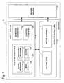
- FIG. 1is a schematic block diagram of a machine with a fast-acting safety system.
- FIG. 2is a schematic diagram of an exemplary safety system in the context of a machine having a circular blade.
- FIG. 3is a side elevation of a radial arm saw equipped with a safety system.
- FIG. 4is a side elevation of a miter saw equipped with a safety system.
- FIG. 5is a side elevation of a pneumatic cut-off saw equipped with a safety system.
- FIG. 6is a side elevation of a pneumatic cut-off saw equipped with an alternative safety system.
- FIG. 7is a side elevation of a pneumatic cut-off saw equipped with a second alternative safety system.
- FIG. 8is a side elevation of a pneumatic cut-off saw equipped with a third alternative safety system.
- FIG. 9is a magnified view of an exemplary locking assembly for use in the safety system of FIG. 8 .
- FIG. 10is an isometric view of a clamping device for use in the locking assembly of FIG. 9 .
- FIG. 11is a cross-sectional view showing an alternative clamping device.
- FIG. 12is a cross-sectional view showing another alternative clamping device.
- FIG. 13is a cross-sectional view showing another alternative clamping device.
- FIG. 14is a side elevation of a pneumatic cut-off saw equipped with a fourth alternative safety system.
- FIG. 15is a side elevation of a pneumatic cut-off saw equipped with a fifth alternative safety system
- FIG. 16a front elevation of the pneumatic cut-off saw of FIG. 15 with a portion of the operative structure indicated in dash line.
- Machine 10may be any of a variety of different types and configurations of machine adapted for cutting workpieces, such as wood, plastic, etc.
- Machine 10includes an operative structure 12 having a cutting tool 14 and a motor assembly 16 adapted to drive the cutting tool.
- Machine 10also includes a safety system 18 configured to minimize the potential of a serious injury to a person using machine 10 .
- Safety system 18is adapted to detect the occurrence of one or more dangerous, or triggering, conditions during use of machine 10 . If such a dangerous condition is detected, safety system 18 is adapted to engage operative structure 12 to limit any injury to the user caused by the dangerous condition.
- Machine 10also includes a suitable power source 20 to provide power to operative structure 12 and safety system 18 .
- Power source 20may be an external power source such as line current, or an internal power source such as a battery.
- power source 20may include a combination of both external and internal power sources.
- power source 20may include two or more separate power sources, each adapted to power different portions of machine 10 .
- operative structure 12may take any one of many different forms, depending on the type of machine 10 .
- operative structure 12may include a stationary housing configured to support motor assembly 16 in driving engagement with cutting tool 14 .
- operative structure 12may include a movable structure configured to carry cutting tool 14 between multiple operating positions.
- operative structure 12may include one or more transport mechanisms adapted to convey a workpiece toward and/or away from cutting tool 14 .
- operative structure 12typically takes the form of an arbor block pivotally coupled to a base or frame.
- Cutting tool 14is mounted on the arm and pivotal upward toward a workpiece supported by the base.
- Safety system 18includes a detection subsystem 22 , a reaction subsystem 24 and a control subsystem 26 .
- Control subsystem 26may be adapted to receive inputs from a variety of sources including detection subsystem 22 , reaction subsystem 24 , operative structure 12 and motor assembly 16 .
- the control subsystemmay also include one or more sensors adapted to monitor selected parameters of machine 10 .
- control subsystem 26typically includes one or more instruments operable by a user to control the machine.
- the control subsystemis configured to control machine 10 in response to the inputs it receives.
- Detection subsystem 22is configured to detect one or more dangerous, or triggering, conditions during use of machine 10 .
- the detection subsystemmay be configured to detect that a portion of the user's body is dangerously close to, or in contact with, a portion of cutting tool 14 .
- the detection subsystemmay be configured to detect the rapid movement of a workpiece due to kickback by the cutting tool, as is described in U.S. Provisional Patent Application Ser. No. 60/182,866, filed Feb. 16, 2000, the disclosure of which is herein incorporated by reference.
- detection subsystem 22may inform control subsystem 26 of the dangerous condition, which then activates reaction subsystem 24 .
- the detection subsystemmay be adapted to activate the reaction subsystem directly.
- reaction subsystem 24is configured to engage operative structure 12 quickly to prevent serious injury to the user. It will be appreciated that the particular action to be taken by reaction subsystem 24 will vary depending on the type of machine 10 and/or the dangerous condition that is detected. For example, reaction subsystem 24 may be configured to do one or more of the following: stop the movement of cutting tool 14 , disconnect motor assembly 16 from power source 20 , place a barrier between the cutting tool and the user, retract the cutting tool from its operating position, etc. The reaction subsystem may be configured to take a combination of steps to protect the user from serious injury. Placement of a barrier between the cutting tool and teeth is described in more detail in U.S. Provisional Patent Application Ser. No. 60/225,206, filed Aug.
- reaction subsystem 24typically will vary depending on which action(s) are taken.
- reaction subsystem 24is configured to stop the movement of cutting tool 14 and includes a brake mechanism 28 , a biasing mechanism 30 , a restraining mechanism 32 , and a release mechanism 34 .
- Brake mechanism 28is adapted to engage operative structure 12 under the urging of biasing mechanism 30 .
- restraining mechanism 32holds the brake mechanism out of engagement with the operative structure.
- the brake mechanismupon receipt of an activation signal by reaction subsystem 24 , the brake mechanism is released from the restraining mechanism by release mechanism 34 , whereupon, the brake mechanism quickly engages at least a portion of the operative structure to bring the cutting tool to a stop.
- FIG. 2one example of the many possible implementations of safety system 18 is shown.
- System 18is configured to engage an operative structure having a cutting tool in the form of a circular blade 40 mounted on a rotating shaft or arbor 42 .
- Blade 40includes a plurality of cutting teeth (not shown) disposed around the outer edge of the blade.
- brake mechanism 28is adapted to engage the teeth of blade 40 and stop rotation of the blade.
- detection subsystem 22is adapted to detect the dangerous condition of the user coming into contact with blade 40 .
- the detection subsystemincludes a sensor assembly, such as contact detection plates 44 and 46 , capacitively coupled to blade 40 to detect any contact between the user's body and the blade.
- the blade, or some larger portion of cutting tool 14is electrically isolated from the remainder of machine 10 .
- detection subsystem 22may include a different sensor assembly configured to detect contact in other ways, such as optically, resistively, etc.
- the detection subsystemis adapted to transmit a signal to control subsystem 26 when contact between the user and the blade is detected.
- Various exemplary embodiments and implementations of detection subsystem 22are described in more detail in U.S. Provisional Patent Application Ser.
- Control subsystem 26includes one or more instruments 48 that are operable by a user to control the motion of blade 40 .
- Instruments 48may include start/stop switches, speed controls, direction controls, etc.
- Control subsystem 26also includes a logic controller 50 connected to receive the user's inputs via instruments 48 .
- Logic controller 50is also connected to receive a contact detection signal from detection subsystem 22 . Further, the logic controller may be configured to receive inputs from other sources (not shown) such as blade motion sensors, workpiece sensors, etc. In any event, the logic controller is configured to control operative structure 12 in response to the user's inputs through instruments 48 .
- control subsystem 26Various exemplary embodiments and implementations of control subsystem 26 are described in more detail in U.S. Provisional Patent Application Ser. No. 60/225,059, filed Aug. 14, 2000 and U.S. Provisional Patent Application Ser. No. 60/225,094, filed Aug. 14, 2000, the disclosures of which are herein incorporated by reference.
- brake mechanism 28includes a pawl 60 mounted adjacent the edge of blade 40 and selectively moveable to engage and grip the teeth of the blade.
- Pawl 60may be constructed of any suitable material adapted to engage and stop the blade.
- the pawlmay be constructed of a relatively high strength thermoplastic material such as polycarbonate, ultrahigh molecular weight polyethylene (UHMW), Acrylonitrile Butadiene Styrene (ABS), etc., or a metal such as aluminum, etc. It will be appreciated that the construction of pawl 60 will vary depending on the configuration of blade 40 . In any event, the pawl is urged into the blade by a biasing mechanism such as a spring 66 .
- a biasing mechanismsuch as a spring 66 .
- pawl 60is pivoted into the teeth of blade 40 . It should be understood that sliding or rotary movement of pawl 60 may also be used.
- the springis adapted to urge pawl 60 into the teeth of the blade with sufficient force to grip the blade and quickly bring it to a stop.
- the pawlis held away from the edge of the blade by a restraining mechanism such as a fusible member 70 .
- the fusible memberis constructed of a suitable material adapted to restrain the pawl against the bias of spring 66 , and also adapted to melt under a determined electrical current density. Examples of suitable materials for fusible member 70 include NiChrome wire, stainless steel wire, etc.
- the fusible memberis connected between the pawl and a contact mount 72 .
- fusible member 70holds the pawl relatively close to the edge of the blade to reduce the distance pawl 60 must travel to engage blade 40 . Positioning the pawl relatively close to the edge of the blade reduces the time required for the pawl to engage and stop the blade.
- the pawlis held approximately 1/32-inch to 1 ⁇ 4-inch from the edge of the blade by fusible member 70 ; however other pawl-to-blade spacings may also be used within the scope of the invention.
- Pawl 60is released from its unactuated, or cocked, position to engage blade 40 by a release mechanism in the form of a firing subsystem 76 .
- the firing subsystemis coupled to contact mount 72 , and is configured to melt fusible member 70 by passing a surge of electrical current through the fusible member.
- Firing subsystem 76is coupled to logic controller 50 and activated by a signal from the logic controller. When the logic controller receives a contact detection signal from detection subsystem 22 , the logic controller sends an activation signal to firing subsystem 76 , which melts fusible member 70 , thereby releasing the pawl to stop the blade.
- reaction subsystem 24are described in more detail in U.S. Provisional Patent Application Ser. No.
- safety system 18includes a replaceable cartridge 80 having a housing 82 .
- Pawl 60 , spring 66 , fusible member 70 and contact mount 72are all mounted within housing 82 .
- other portions of safety system 18may be mounted within the housing.
- safety system 18may be replaced separately or reused as appropriate.
- Various exemplary embodiments and implementations of a safety system using a replaceable cartridgeare described in more detail in U.S. Provisional Patent Application Ser. No. 60/225,201, filed Aug. 14, 2000 and U.S. Provisional Patent Application Ser. No. 60/225,212, filed Aug. 14, 2000, the disclosures of which are herein incorporated by reference.
- reaction subsystem 24may include a system to stop the cutting tool from continuing to move into the workpiece. Stopping the translational motion of the cutting tool can minimize any injury from accidental contact between a user and the cutting tool.
- FIG. 3illustrates an exemplary implementation of a system to stop the translational motion of a cutting tool in the context of a radial arm saw 1100 .
- radial arm saw 1100includes a horizontal base 1102 , a vertical support column 1104 extending upward from base 1102 , and a guide arm 1106 that extends from column 1104 vertically spaced above base 1102 .
- a carriage 1108is slidably coupled to the underside of guide arm 1106 .
- the bottom end of carriage 1108is connected to a saw housing 1110 and to a motor assembly 1112 , allowing a blade 1114 to be pulled across the base to cut workpieces (not shown) supported on the base.
- Radial arm saw 1100is preferably equipped with a system as described above to stop the spinning of the blade, which includes a brake pawl 60 in a cartridge 80 .
- a usergrasps a handle 1116 on the saw and pulls the saw and blade across a workpiece on base 1102 . In so doing, a user may accidentally pull the saw into contact with a misplaced finger or some other part of his body.
- brake pawl 60works to stop the blade from spinning, but since the user may be pulling the saw toward his or her body when contact is detected, the saw may continue to move toward the user even after pawl 60 has stopped the blade. This continued movement may cause the stopped blade to be driven over a portion of the user's body (e.g., the user's hand), causing further injury.
- a system to stop the movement of the carriage and saw along the guide arm once contact is detected between the blade and the user's bodyaddresses this issue.
- FIG. 3illustrates two examples.
- One exampleincludes a pivoting wedge assembly 1118 .
- Assembly 1118includes a wedge or pawl 1120 pivotally coupled to carriage 1108 .
- An actuator 1122 mounted on carriage 1108is operatively coupled to the control and detection subsystems associated with brake pawl 60 and cartridge 80 so that when pawl 60 is released, actuator 1122 engages wedge 1120 .
- actuator 1122maintains the wedge spaced-apart from guide arm 1106 .
- the detection systemsends an actuation signal to actuator 1122 .
- the signal sent to actuator 1122may be the same signal that triggers the release of brake pawl 60 , or it may be a different signal.
- the actuatordrives against wedge 1120 , causing it to pivot into the guide arm, preventing further movement of the guide bracket forward along the guide arm.
- the wedgemay be constructed or coated with a high friction material such as rubber, and/or may be configured with teeth, etc., to increase its braking action.
- the other exemplary braking configuration illustrated in FIG. 3includes a lockable spool assembly 1124 .
- Assembly 1124may be used in place of, or in addition to, wedge assembly 1118 .
- the lockable spool assemblyincludes a spring-loaded spool 1126 mounted on support column 1104 .
- One end of a tether or cable 1128is attached to carriage 1108 , while the other end is wound around spool 1126 .
- the spoolunwinds, allowing the tether to extend.
- the spring-loading of the spoolensures that the spool maintains a slight tension on the tether and retracts the tether around the spool when the user pushes the saw back toward the support column.
- Assembly 1124also includes a spool brake, such as pawl 1130 , operatively coupled to the control and detection systems associated with brake pawl 60 .
- a spool brakesuch as pawl 1130
- pawl 1130operatively coupled to the control and detection systems associated with brake pawl 60 .
- an actuation signalis sent to the spool brake, causing the spool to lock.
- the tetherprevents further movement of the saw away from support column 1104 .
- the lockable spoolmay be contained in, or placed adjacent to, cartridge 80 , in which case the tether would run from the spool backward to support column 1104 .
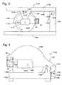
- FIG. 4illustrates an exemplary implementation of a system to stop the translational motion of a cutting tool in the context of a miter saw 1150 .
- miter saw 1150may be any type of miter saw including a simple miter saw, compound miter saw, sliding compound miter saw, etc.
- miter saw 1150includes a base or stand 1152 adapted to hold the workpiece to be cut.
- a swing arm 1154is pivotally coupled to base 1152 to allow the arm to pivot downward toward the base.
- Attached to arm 1154is a housing 1156 adapted to at least partially enclose a circular blade 1158 .
- a motor assembly 1112is coupled to the housing, and includes a rotating arbor 1160 on which the blade is mounted.
- Motor assembly 1112includes a handle 1162 with a trigger (not shown) operable to run the saw.
- An optional blade guard(not shown) may extend from the bottom of housing 1156 to cover any portion of the blade exposed from the housing.
- a personuses miter saw 1150 by lifting the saw up, placing a workpiece on base 1152 , and then bringing the saw down onto the workpiece to cut the workpiece.
- Miter saw 1150also preferably includes a brake pawl 60 in a cartridge 80 configured to stop the spinning of the blade, as described above.
- a saw blade spinning at several thousand revolutions per minutehas substantial angular momentum.
- the brake pawlengages and stops the blade, the angular momentum must be transferred to the brake.
- the swing arm of the miter sawis free to pivot in the direction of blade rotation, the angular momentum of the blade may be transferred to the swing arm when the blade is suddenly stopped, causing the swing arm to swing downward. This sudden and forceful downward movement of the swing arm may cause injury to the user if a portion of the user's body is beneath the blade.
- the pivotal connection between the swing arm and the base of the miter sawmay be electrically lockable, for example using an electromagnetic leaf brake, to prevent the arm from pivoting.
- the signal to lock the connectionmay be provided by the detection subsystem.
- most such arrangementstransfer the angular momentum to the swing arm/base assembly. Depending on the weight and balance of the saw, the angular momentum may be sufficient to cause the entire saw to overturn. Therefore, it may be desirable to secure the base to a stable surface with clamps, bolts, etc.
- FIG. 4shows one way to prevent the sudden downward movement of swing arm 1154 .
- Swing arm 1154includes a cam portion 1170 having a cam surface 1172 .
- Cam portion 1170may be integral with the swing arm and housing 1156 .
- a stopping pawl 1174is mounted to vertical support 1104 adjacent cam surface 1172 , and an actuator 1176 is positioned adjacent pawl 1174 .
- the actuator 1176is operatively coupled to the control and detection subsystems associated with brake pawl 60 and cartridge 80 so that when pawl 60 is released, actuator 1176 engages pawl 1174 . During normal operation, actuator 1176 maintains the pawl spaced-apart from cam surface 1172 .
- the detection systemsends an actuation signal to actuator 1176 , which may be the same or a different signal that triggers the release of brake pawl 60 .
- the actuatordrives against pawl 1174 , causing it to pivot into cam surface 1172 , preventing further movement of the swing arm.
- Pawl 1174may be constructed or coated with a high friction material such as rubber, and/or may be configured with teeth, etc., to increase its braking action.
- Cam portion 1170may be modified so that it extends as far as possible from the point around which it pivots, in order to provide as great a moment arm as possible to help stop the downward motion of the swing arm.
- the miter saw in FIG. 4also includes a piston/cylinder 1180 connected between swing arm 1154 and base 1152 . That piston/cylinder limits the speed with which the swing arm can pivot relative to the base, and can also serve to stop or limit the downward motion of the blade when accidental contact with the blade is detected.
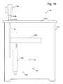
- FIG. 5illustrates an alternative translation stop mechanism implemented in the context of a pneumatic up-cut chop saw 1181 .
- Chop saw 1181includes a blade 40 mounted to a pivotal arbor block 1182 .
- the blade and/or some associated portion of the saw,are electrically isolated and coupled to a detection system such as described above and in the incorporated references. This arrangement allows detection of contact of the blade with a user as described in those cases.
- actuating mechanism 1183takes the form of a pneumatic cylinder.
- actuating mechanism 1183may take any other form configured to raise and lower the blade including a hydraulic cylinder, mechanically-driven shaft, etc.
- Exemplary cylinder 1183may be actuated by the user, such as by stepping on a foot switch, or may be operated by an electronic controller. In either case, a solenoid valve (not shown) is normally provided to control the delivery of air to the cylinder.
- a blade guard or guard structure 1184is provided to cover the blade as it emerges through the top of the table.
- the blade guardmoves down upon actuation of the saw to serve as a hold down on the material being cut.
- a defined portion 1185 of the blade guardsuch as a metal strip along the bottom of the blade guard, can therefore be electrically isolated and used as an electrode to also detect contact with a user as described above.
- the blade guardis not spinning, it may be desirable to use a conductive or other type of coupling rather than capacitive coupling to detect contact. It will be appreciated that any suitable coupling system can be utilized. In any case, the detection system then monitors for contact between the bottom of the blade guard and a user.
- control subsystemonly treat a detected contact as a dangerous condition and trigger the reaction subsystem during actual actuation of the saw. Otherwise, inadvertent contact when the user is positioning stock to be cut may result in false triggers where no danger was present. However, if the bottom of the guard is touching the user at any time during the actuation cycle of the saw, the reaction subsystem should be triggered.
- the user's handmay be covered by a glove or may be positioned under the board, in most cases it is not sufficient just to use the blade guard for contact detection. Therefore, it usually is desirable to couple the detection subsystem to both the blade guard and the blade. In such case, a user would be protected under all circumstances since the reaction subsystem would be triggered when the blade cut through the glove and/or board and contacted the user's hand.
- a defined region or portion of the table of the saw around the blade openingcan be isolated and monitored for user contact, just as with the blade guard.
- a metal strip 2-cm wide with a slot for the blade to pass throughcan be installed in an insulating material into the portion of the table through which the blade projects. This strip can then serve as a contact detection electrode. Therefore, if a user's hand contacts the electrode on the table, i.e., is on the table within 1-cm of the blade, when the saw is actuated, the reaction subsystem can be triggered. Similar systems can of course be used on many other types of woodworking machinery, such as on the infeed section of a planer, to detect dangerous conditions.
- Saw 1181includes a reaction subsystem 24 configured to interrupt the upward motion of the saw if contact with a user is detected at the guard/table or by the blade.
- Reaction subsystem 24includes a first link 1186 a extending between arbor block 1182 and an end of a lever link 1186 b .
- the lever linkpivots about a pivot point 1187 and is connected at the opposite end to a second link 1186 c .
- the pivot pointis positioned so that the second link travels substantially farther than the first link during actuation of the saw.
- a spring 1188is connected to the free end of the second link to tension the entire linkage mechanism against upward motion of the saw. This tension, although not essential, is beneficial to insure that any slop in the linkage is already taken up when the brake is actuated, as described below, to thereby minimize upward travel after actuation.
- the reaction subsystemalso includes a brake mechanism 28 in the form of a pawl 1189 .
- the pawlis mounted on a pivot 1190 and biased toward the second link by a biasing mechanism 30 in the form of a stack 1191 of Belleville springs.
- the springsare preferably positioned to push the pawl against the pivot in a direction to minimize any slop or play in uptake when the face of the pawl contacts the second link. Again, this reduces the upward movement of the blade after triggering of the brake.
- a restraining mechanism in the form of an electromagnet 1192is magnetically connected to the upper side of the pawl to hold the pawl against the biasing mechanism.
- the pawlis constructed from a hard, magnetic metal and is provided with serrations on the front surface to grip or bite into the link when engaged.
- the pawlcan also be provided with a magnetic plate attached to the top to engage the electromagnet.
- a slide surface 1193is provided opposite the pawl to guide the second link and provide a support for the second link when the pawl pushes against the linkage.
- a retainer 1194holds the second link against the slide surface so no play is present when the pawl is actuated and to insure that the link does not accidentally contact the pawl prior to release.
- the face of the pawlis preferably positioned so that it rides very close—preferably between 0.1 mm and 2 mm—to minimize the time required for engagement with the link.
- a currentis driven through the electromagnet to hold the pawl.
- the electrical currentis interrupted, and preferably a current of the opposite polarity is applied for a short period of time, to quickly release the pawl to be pushed over into contact with the second linkage by the spring.
- the pawlthen immediately binds against the second linkage to prevent further upward motion of the blade.
- the pneumatic cylinderis reversed to begin retraction of the blade.
- Brake mechanism 28can stop upward motion of the blade in 1-5 milliseconds and restrain the pneumatic cylinder until the solenoid valve can be reversed to retract the blade.
- the retractionbegins in substantially less than 100 milliseconds so that the user does not have time to react and jerk their hand across the still spinning blade, thereby causing more serious injury.
- a shoulder 1195 located on the second linkis positioned to reset the pawl against the electromagnet when the blade is fully lowered.
- the shoulderpushes against the underside of the pawl to lift the pawl back into contact with the electromagnet. This resets the system so that it is ready for repeated use.
- the electromagnetic releasecan be used interchangeably with the fusible member release previously described.
- the fusible memberis generally cheaper to implement, but has the disadvantage of being suitable for only a single use.
- FIG. 6An alternative reaction subsystem configuration to stop translational movement similar to the system of FIG. 5 is shown in FIG. 6 .
- the system of FIG. 6includes only a single link 1186 connected to an extension arm 1195 connected to arbor block 1182 .
- the extension armprovides some mechanical advantage, similar to the lever link of FIG. 5 .
- pawl 1189grips link 1186 as previously described to stop upward movement of the blade.
- spring 1188maintains a tension on the link to take up any play that may be present or develop in the mechanism. It should be understood that the system of FIGS. 5 and 6 could be used together to create additional mechanical advantage in the translation stopping mechanism.
- FIG. 7illustrates another reaction subsystem similar to those of FIGS. 5 and 6 .
- the brakeis mounted on a carriage 1196 , which slides along link 1186 on bushing 1197 .
- the carriageis mounted to a brace 1198 that is coupled to arbor block 1182 to pivot therewith.
- the arbor blockpivots upwardly, the carriage is driven along the link.
- the pawlis released to catch against the surface of the link and stop the upward travel of the blade.
- springs 1188 and 1191are positioned to eliminate any play in the translation stop mechanism.
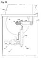
- FIG. 8illustrates a further alternative configuration of reaction subsystem 24 adapted for use on a pneumatic up-cut chop saw 1181 to stop the upward movement of blade 40 and then retract the blade.
- the bladeis mounted on an arbor or spindle 1200 supported within a spindle housing 1202 by one or more bearings (not shown).
- the spindle housingis electrically isolated from arbor block 1182 , extension arm 1199 and the remainder of chop saw. 1181 by spacer blocks 1204 .
- the spacer blocksmay be constructed of phenolic or some other electrically-insulating material.
- the detection subsystemmay be coupled directly to the spindle housing.
- the relative close spacing between spindle 1200 and the spindle housingcreates a capacitive coupling between the spindle housing and the spindle.
- the spindle and spindle housingmay also be conductively coupled through the bearings.
- blade 40is coupled to the spindle housing and the detection subsystem through the spindle.
- Reaction subsystem 24includes a brake mechanism 28 and a retraction mechanism 1206 .
- Brake mechanism 28includes a brace member 1208 pivotally coupled to the end of extension arm 1199 .
- a locking assembly 1210is pivotally coupled to a portion of the chop saw frame. Locking assembly 1210 is configured to receive and slide along brace member 1208 as the brace member moves up and down with arbor block 1182 and extension arm 1199 . Upon receipt of an activation signal, locking assembly 1210 is configured to quickly clamp onto the brace member and prevent further upward movement of the brace member. As a result, upward movement of the blade is also stopped.
- retraction mechanism 1206is configured to retract the blade to its lowermost position below the table top.
- locking assembly 1210is configured to prevent only upward movement of brace member 1208 so that retraction mechanism 1206 is able to move the blade downward after the brake mechanism has been activated.
- the locking assemblymay be configured to release the brace member once the retraction mechanism begins urging the arbor block downward.
- retraction mechanism 1206includes a pair of pneumatic solenoid valves 1212 adapted to reverse the direction of pneumatic cylinder 1183 in response to the activation signal.
- retraction mechanism 1206may include any other suitable mechanism adapted to urge blade 40 downward.
- locking assembly 1210may be configured in any of a variety of different ways to quickly clamp onto brace member 1208 and stop upward movement of the blade.
- the locking assemblyincludes a clamping device 1214 adapted to slide along and selectively bind against brace member 1208 .
- clamping device 1214includes an orifice 1216 adapted to receive and slide along brace member 1208 when the orifice is substantially axially aligned with the brace member.
- clamping device 1214is pivoted relative to the brace member (as indicated by dash lines in FIG. 9 )
- the edges of orifice 1216bind against and lock-up on the sides of the brace member.
- Brace member 1208 and clamping device 1214may be constructed from any of a variety of different materials having either the same or different hardnesses.
- the clamping devicemay be formed from hardened steel while the brace member is formed from unhardened steel, or vice versa.
- both the clamping device and brace membermay be formed of unhardened steel or hardened steel.
- the brace member and/or the clamping devicemay include structure (e.g., serrations, etc.) adapted to enhance the friction or gripping action of the clamping device on the brace member.
- one or both of brace member 1208 and clamping device 1214may be formed of different materials.
- brace member 1208is formed of unhardened O 1 steel drill rod with a smooth surface
- clamping device 1214is formed of oil hardened steel. Forming the clamping device from a harder material than the brace member allows the clamping device to slightly deform or ‘bite into’ the brace member during braking.
- Orifice 1216typically is sized to fit relatively closely about brace member 1208 .
- the brace memberhas a diameter of approximately 0.500-inch, while the orifice has a diameter in the range of approximately 0.500-inch to approximately 0.503-inch.
- the orificemay be any size or shape adapted to bind against the brace member.
- the sides of orifice 1216may be substantially cylindrical so that the opposite edges of the orifice form gripping edges that bind against the brace member.
- the sides of the orificemay be shaped to bind against the brace member at locations between the opposite edges of the orifice. For example, FIGS.
- FIG. 11-12illustrate alternative orifice configurations adapted to present different gripping edges on the sides of the brace member.
- the sides of orifice 1216present generally conical surfaces having flat apexes 1218 facing inward toward the brace member. The width of the apexes may be varied to select the axial distance between gripping edges.
- opposing sides of the orificemay have beveled regions 1220 extending in opposite directions to reduce the axial distance between gripping edges within the orifice.
- opposing sides of the orificemay have offset regions 1222 extending in opposite directions to reduce the axial distance between gripping edges within the orifice.
- the orifice configurationtypically is selected to achieve the quickest lock-up on the brace member, and may depend on the relative sizes, shapes and/or hardnesses of the brace member and clamping device.
- Exemplary locking assembly 1210also includes a housing 1224 adapted to support the clamping device in a constant orientation relative to the brace member until the activation signal is received.
- the housingmay be pivotally coupled to chop saw 1181 by one or more shoulder bolts 1230 adapted to engage mounting structures 1232 on the housing.
- the housingincludes one or more bushings 1234 or similar structures configured to receive and slide along the brace member. Bushings 1234 fit relatively closely about the brace member to maintain housing 1224 in a constant orientation relative to the brace member as the brace member slides within the housing.
- Clamping device 1214is mounted in a cavity 1236 formed within housing 1202 and positioned so that orifice 1216 is axially aligned with the brace member when the brace member is received within the housing.
- one end 1237 of clamping device 1214is positioned against a support base 1238 disposed within cavity 1236 .
- Support base 1238includes a pair of guide structures 1239 adapted to fit on either side of end 1237 and generally align the clamping device within the housing.
- the clamping deviceis held in place against support base 1238 by a fusible member 70 extending over an electrically-insulating stud 1240 mounted on end 1237 by a screw 1242 or similar mechanism.
- Stud 1240may be constructed of phenolic or some other electrically-insulating material, and serves to insulate clamping device 1214 from any electric charge present on the fusible member.
- fusible member 70may be positioned in direct contact with the clamping device.
- fusible member 70is anchored at one end to a mounting post 1244 , and at the other end to a contact mount 72 such as described above.
- Contact mount 72is coupled to a firing subsystem 76 disposed on or near housing 1224 . As described above, the firing subsystem applies a sudden current surge to contact mount 72 in response to an activation signal, thereby melting fusible member 70 and releasing clamping device 1214 .
- Support base 1238includes a hole 1248 adapted to receive the spring and sized so that the spring is held in compression when clamping device 1214 is positioned against the support base.
- clamping device 1214abuts against a shelf structure 1250 defined by cavity 1236 .
- the shelf structureis positioned relative to support base 1238 so that orifice 1216 is aligned to slide along the brace member when the clamping device is held against the support base.
- end 1237is urged upward while end 1249 is held against shelf structure 1250 .
- clamping device 1214pivots relative to the brace member until the edges of orifice 1216 bind against the brace member. Any additional upward force on the brace member relative to the clamping device tends to increase the locking grip of the clamping device on the brace member. Thus, further upward movement of the brace member relative to the housing is prevented.
- a pin 1252 or similar structuremay be positioned beneath end 1249 to ensure the clamping device pivots in the opposite direction to return to an unlocked orientation when the brace member moves downward relative to the housing.
- locking assembly 1210also includes a bolt 1254 threaded through housing 1224 above clamping device 1214 .
- Bolt 1254may be screwed into the housing to cock or push the clamping device into its unactuated position on support base 1238 against the bias of spring 1246 .
- the clamping devicemay include a depression 1256 adapted to receive the lower end of bolt 1254 . This allows a user to automatically align the clamping device relative to the brace member using bolt 1254 . Once a new fusible link is installed, bolt 1254 is screwed out to ensure the clamping device has sufficient clearance to pivot into binding engagement with the brace member. Alternatively, a different mechanism may be used to cock the clamping device against the bias of spring 1246 .
- exemplary locking assembly 1210may be used with any of the embodiments described above. Additionally, many modifications and variations of locking assembly 1210 are possible. Several examples of alternative locking assemblies are described in U.S. Provisional Patent Application Ser. No. 60/270,941, filed Feb. 22, 2001, and U.S. Provisional Patent Application Ser. No. 60/270,942, filed Feb. 22, 2001, the disclosures of which are herein incorporated by reference.
- FIG. 14Another alternative configuration of reaction subsystem 24 adapted for use on a pneumatic up-cut chop saw 1181 is illustrated in FIG. 14 , in which brake mechanism 28 takes the form of a hydraulic cylinder 1258 .
- a lower portion 1260 of cylinder 1258is pivotally coupled to the frame of chop saw 1181 or some other suitable support structure.
- the hydraulic cylinderincludes an extension rod 1262 slidably extending from the top of the cylinder. The upper end of the extension rod is pivotally coupled to extension arm 1195 .
- the lower end of extension rod 1262is coupled to a piston 1264 housed to slide within cylinder 1258 .
- extension rod 1262moves up and down, thereby pulling and pushing piston 1264 up and down within cylinder 1258 .
- Brake mechanism 28also includes a hydraulic control circuit 1264 adapted to regulate the flow of hydraulic fluid within cylinder 1258 .
- Control circuit 1264 and cylinder 1258form a closed hydraulic system. Under normal operating conditions, the hydraulic control circuit forms a fluid channel between the top and bottom of cylinder 1258 .
- extension rod 1262pulls piston 1264 upward.
- hydraulic fluidis pushed out of the top of cylinder 1258 , through the control circuit and into the bottom of the cylinder.
- extension rod 1262pushes piston 1264 downward, thereby pushing hydraulic fluid from the bottom of the cylinder, through the control circuit to the top of the cylinder.
- control circuit 1264includes a two-way control valve 1266 and a one-way check valve 1268 .
- Control valve 1266is operable by the control system (not shown) to open or close a bi-directional channel between the top and bottom of cylinder 1258 .
- the control systemis configured to close valve 1266 , thereby closing the hydraulic channel from the top of the cylinder to the bottom of the cylinder is closed.
- the hydraulic fluid selected for use in cylinder 1264is a relatively non-compressible fluid such as oil, etc., to minimize the distance piston 1264 moves upward after valve 1266 has closed.
- Check valve 1268provides a continuous, uni-directional channel from the bottom of cylinder 1258 to the top. Thus, piston 1264 is able to move downward in the cylinder even though control valve 1266 is closed. This allows retraction mechanism 1206 to pull the blade downward upon detection of a dangerous condition. While one exemplary hydraulic control circuit has been shown and described, it will be appreciated by those of skill in the art that the control circuit may be configured in many different ways to achieve the desired operation.
- reaction subsystem 24includes a brake mechanism 28 that is separate from the actuating mechanism that raises and lowers the blade.
- reaction subsystem 24may alternatively be configured to stop the upward movement of the blade without the use of a separate brake mechanism.
- FIGS. 15 and 16illustrate an exemplary embodiment in which actuating mechanism 1183 also functions as the brake mechanism.
- exemplary actuating mechanism 1183takes the form of a pneumatic or hydraulic cylinder.
- the actuating mechanismis configured to be controlled by control subsystem 26 .
- the control subsystemUpon detection of a dangerous condition, the control subsystem causes the cylinder to retract, thereby stopping any upward motion of the blade and retracting the blade below the table 1270 of the chop saw frame 1272 . If the cylinder is already retracted when the dangerous condition is detected, the control subsystem prevents actuation of the cylinder.
- the detection subsystem(not shown) is configured to detect several dangerous conditions including, contact between the user and a defined portion 1185 of guard structure 1184 , contact between the user and a defined portion 1274 of table 1270 , and contact between a user and blade 40 , etc.
- the detection subsystemmay be configured to detect fewer or more dangerous conditions.
- the control subsystemsends a signal to the reaction subsystem, i.e., cylinder 1183 , and stops any upward movement of the blade by reversing the motion of cylinder 1183 , and then retracts the cylinder to retract the blade below the top surface of table 1270 .
- cylinder 1183is configured to reverse and retract quickly relative to the speed with which the cylinder moves the blade upward. This helps ensure that any injury to a user is minimal.
- cylinder 1183is controlled by an electromagnetic solenoid valve, it may be desirable to use a relatively high voltage signal to actuate the valve so as to cause the valve to switch as quickly as possible.
- a 180-volt DC pulse transmitted to a solenoid valve that nominally switches with a 24-volt DC pulsewill typically cause the valve to switch at or near a maximum switching speed.
- the high voltage pulsemay be supplied from a firing subsystem such as described above, including one or more charge storage devices such as capacitors, etc.
- a firing subsystemsuch as described above, including one or more charge storage devices such as capacitors, etc.
- chop sawshave different actuating mechanisms, such as cams, eccentrics, etc., to raise and lower the blade and the above-described safety systems and variations thereof can be applied to such different mechanisms as well.
- the reaction subsystems described abovecan also be used in connection with various other braking or blade retraction systems to obtain combined benefit. For instance, the blade may be braked at the same time as the upward movement of the blade is stopped and reversed to further minimize the chance of serious injury.
Landscapes
- Engineering & Computer Science (AREA)
- Mechanical Engineering (AREA)
- General Engineering & Computer Science (AREA)
- Life Sciences & Earth Sciences (AREA)
- Wood Science & Technology (AREA)
- Forests & Forestry (AREA)
- Sawing (AREA)
Abstract
Description
Claims (13)
Priority Applications (19)
| Application Number | Priority Date | Filing Date | Title |
|---|---|---|---|
| US11/256,757US8065943B2 (en) | 2000-09-18 | 2005-10-24 | Translation stop for use in power equipment |
| US11/348,580US20060123964A1 (en) | 2000-09-29 | 2006-02-06 | Table saw with improved safety system |
| US11/401,050US7788999B2 (en) | 1999-10-01 | 2006-04-10 | Brake mechanism for power equipment |
| US11/401,774US7525055B2 (en) | 1999-10-01 | 2006-04-11 | Switch box for power tools with safety systems |
| US11/445,548US7347131B2 (en) | 1999-10-01 | 2006-06-02 | Miter saw with improved safety system |
| US11/542,938US20070028733A1 (en) | 1999-10-01 | 2006-10-02 | Safety methods for use in power equipment |
| US12/313,162US7789002B2 (en) | 2000-09-29 | 2008-11-17 | Table saw with improved safety system |
| US12/800,607US7895927B2 (en) | 1999-10-01 | 2010-05-19 | Power equipment with detection and reaction systems |
| US12/806,829US9522476B2 (en) | 1999-10-01 | 2010-08-20 | Power equipment with detection and reaction systems |
| US12/806,836US8196499B2 (en) | 1999-10-01 | 2010-08-20 | Power equipment with detection and reaction systems |
| US12/807,147US8402869B2 (en) | 1999-10-01 | 2010-08-27 | Brake mechanism for power equipment |
| US12/807,146US8291797B2 (en) | 1999-10-01 | 2010-08-27 | Table saw with improved safety system |
| US13/442,290US8408106B2 (en) | 1999-10-01 | 2012-04-09 | Method of operating power equipment with detection and reaction systems |
| US13/854,270US20170190012A9 (en) | 1999-10-01 | 2013-04-01 | Power equipment with detection and reaction systems |
| US14/720,552US20150273725A1 (en) | 1999-10-01 | 2015-05-22 | Table saws with detection and reaction systems |
| US14/862,571US9925683B2 (en) | 1999-10-01 | 2015-09-23 | Table saws |
| US15/357,928US9969014B2 (en) | 1999-10-01 | 2016-11-21 | Power equipment with detection and reaction systems |
| US15/362,388US9878380B2 (en) | 1999-10-01 | 2016-11-28 | Table saw throat plates and table saws including the same |
| US15/935,395US10335972B2 (en) | 1999-10-01 | 2018-03-26 | Table Saws |
Applications Claiming Priority (4)
| Application Number | Priority Date | Filing Date | Title |
|---|---|---|---|
| US23345900P | 2000-09-18 | 2000-09-18 | |
| US29208101P | 2001-05-17 | 2001-05-17 | |
| US09/955,418US6957601B2 (en) | 2000-08-14 | 2001-09-17 | Translation stop for use in power equipment |
| US11/256,757US8065943B2 (en) | 2000-09-18 | 2005-10-24 | Translation stop for use in power equipment |
Related Parent Applications (10)
| Application Number | Title | Priority Date | Filing Date |
|---|---|---|---|
| US09/955,418ContinuationUS6957601B2 (en) | 1999-10-01 | 2001-09-17 | Translation stop for use in power equipment |
| US09/955,418Continuation-In-PartUS6957601B2 (en) | 1999-10-01 | 2001-09-17 | Translation stop for use in power equipment |
| US11/208,214ContinuationUS7784507B2 (en) | 1999-10-01 | 2005-08-19 | Router with improved safety system |
| US11/348,580ContinuationUS20060123964A1 (en) | 1999-10-01 | 2006-02-06 | Table saw with improved safety system |
| US12/800,607ContinuationUS7895927B2 (en) | 1999-10-01 | 2010-05-19 | Power equipment with detection and reaction systems |
| US12/806,829ContinuationUS9522476B2 (en) | 1999-10-01 | 2010-08-20 | Power equipment with detection and reaction systems |
| US12/806,830ContinuationUS8191450B2 (en) | 1999-10-01 | 2010-08-20 | Power equipment with detection and reaction systems |
| US12/806,836ContinuationUS8196499B2 (en) | 1999-10-01 | 2010-08-20 | Power equipment with detection and reaction systems |
| US12/807,146ContinuationUS8291797B2 (en) | 1999-10-01 | 2010-08-27 | Table saw with improved safety system |
| US12/807,147ContinuationUS8402869B2 (en) | 1999-10-01 | 2010-08-27 | Brake mechanism for power equipment |
Related Child Applications (14)
| Application Number | Title | Priority Date | Filing Date |
|---|---|---|---|
| US10/050,085ContinuationUS20020056349A1 (en) | 1999-10-01 | 2002-01-14 | Miter saw with improved safety system |
| US10/100,211ContinuationUS9724840B2 (en) | 1999-10-01 | 2002-03-13 | Safety systems for power equipment |
| US11/208,214ContinuationUS7784507B2 (en) | 1999-10-01 | 2005-08-19 | Router with improved safety system |
| US11/218,356ContinuationUS7621205B2 (en) | 1999-10-01 | 2005-09-02 | Band saw with safety system |
| US11/348,580ContinuationUS20060123964A1 (en) | 1999-10-01 | 2006-02-06 | Table saw with improved safety system |
| US11/401,050ContinuationUS7788999B2 (en) | 1999-10-01 | 2006-04-10 | Brake mechanism for power equipment |
| US11/401,774ContinuationUS7525055B2 (en) | 1999-10-01 | 2006-04-11 | Switch box for power tools with safety systems |
| US11/445,548ContinuationUS7347131B2 (en) | 1999-10-01 | 2006-06-02 | Miter saw with improved safety system |
| US11/542,938ContinuationUS20070028733A1 (en) | 1999-10-01 | 2006-10-02 | Safety methods for use in power equipment |
| US12/800,607ContinuationUS7895927B2 (en) | 1999-10-01 | 2010-05-19 | Power equipment with detection and reaction systems |
| US12/806,830ContinuationUS8191450B2 (en) | 1999-10-01 | 2010-08-20 | Power equipment with detection and reaction systems |
| US12/806,829ContinuationUS9522476B2 (en) | 1999-10-01 | 2010-08-20 | Power equipment with detection and reaction systems |
| US12/806,836ContinuationUS8196499B2 (en) | 1999-10-01 | 2010-08-20 | Power equipment with detection and reaction systems |
| US12/807,147ContinuationUS8402869B2 (en) | 1999-10-01 | 2010-08-27 | Brake mechanism for power equipment |
Publications (2)
| Publication Number | Publication Date |
|---|---|
| US20060032352A1 US20060032352A1 (en) | 2006-02-16 |
| US8065943B2true US8065943B2 (en) | 2011-11-29 |
Family
ID=35798749
Family Applications (1)
| Application Number | Title | Priority Date | Filing Date |
|---|---|---|---|
| US11/256,757Expired - Fee RelatedUS8065943B2 (en) | 1999-10-01 | 2005-10-24 | Translation stop for use in power equipment |
Country Status (1)
| Country | Link |
|---|---|
| US (1) | US8065943B2 (en) |
Cited By (18)
| Publication number | Priority date | Publication date | Assignee | Title |
|---|---|---|---|---|
| US20110048193A1 (en)* | 2009-08-26 | 2011-03-03 | Credo Technology Corporation | Table saw with pressure operated actuator |
| US20110048190A1 (en)* | 2009-08-26 | 2011-03-03 | Credo Technology Corporation | Table saw with belt stop |
| US20110048188A1 (en)* | 2009-08-26 | 2011-03-03 | Credo Technology Corporation | Table saw with actuator module |
| US20110048194A1 (en)* | 2009-08-26 | 2011-03-03 | Credo Technology Corporation | Table saw with reset mechanism |
| US20110048195A1 (en)* | 2009-08-26 | 2011-03-03 | Credo Technology Corporation | Table saw with ratchet mechanism |
| US20110048189A1 (en)* | 2009-08-26 | 2011-03-03 | Credo Technology Corporation | Table saw with positive locking mechanism |
| US20110048205A1 (en)* | 2009-08-26 | 2011-03-03 | Credo Technology Corporation | Table saw with dust shield |
| US20120167732A1 (en)* | 2000-08-14 | 2012-07-05 | Gass Stephen F | Detection system for power equipment |
| US8297159B2 (en) | 2009-08-26 | 2012-10-30 | Robert Bosch Gmbh | Table saw with dropping blade |
| US8578825B2 (en) | 2009-08-26 | 2013-11-12 | Robert Bosch Gmbh | Table saw with mechanical fuse |
| US8714061B2 (en) | 2009-08-26 | 2014-05-06 | Robert Bosch Gmbh | Table saw with actuator reset mechanism |
| US20140290799A1 (en)* | 1999-10-01 | 2014-10-02 | Stephen F. Gass | Power equipment with detection and reaction systems |
| US9511429B2 (en) | 2013-03-15 | 2016-12-06 | Robert BoschTool Corporation | Blade drop for power device and method of manufacturing thereof |
| US9517516B2 (en) | 2013-03-14 | 2016-12-13 | Robert Bosch Tool Corporation | Blade drop power tool with dust management |
| US9623498B2 (en) | 2003-12-31 | 2017-04-18 | Sd3, Llc | Table saws |
| US9724840B2 (en) | 1999-10-01 | 2017-08-08 | Sd3, Llc | Safety systems for power equipment |
| US9927796B2 (en) | 2001-05-17 | 2018-03-27 | Sawstop Holding Llc | Band saw with improved safety system |
| US11085582B2 (en) | 2017-08-30 | 2021-08-10 | Milwaukee Electric Tool Corporation | Power tool having object detection |
Families Citing this family (44)
| Publication number | Priority date | Publication date | Assignee | Title |
|---|---|---|---|---|
| US7098800B2 (en) | 2003-03-05 | 2006-08-29 | Sd3, Llc | Retraction system and motor position for use with safety systems for power equipment |
| US7171879B2 (en) | 2001-07-02 | 2007-02-06 | Sd3, Llc | Discrete proximity detection system |
| US7290472B2 (en) | 2002-01-14 | 2007-11-06 | Sd3, Llc | Miter saw with improved safety system |
| US7024975B2 (en) | 2000-08-14 | 2006-04-11 | Sd3, Llc | Brake mechanism for power equipment |
| US7827890B2 (en) | 2004-01-29 | 2010-11-09 | Sd3, Llc | Table saws with safety systems and systems to mount and index attachments |
| US7350445B2 (en) | 2003-08-20 | 2008-04-01 | Sd3, Llc | Brake cartridge for power equipment |
| US6857345B2 (en) | 2000-08-14 | 2005-02-22 | Sd3, Llc | Brake positioning system |
| US20050041359A1 (en)* | 2003-08-20 | 2005-02-24 | Gass Stephen F. | Motion detecting system for use in a safety system for power equipment |
| US7350444B2 (en) | 2000-08-14 | 2008-04-01 | Sd3, Llc | Table saw with improved safety system |
| US7600455B2 (en) | 2000-08-14 | 2009-10-13 | Sd3, Llc | Logic control for fast-acting safety system |
| US8061245B2 (en) | 2000-09-29 | 2011-11-22 | Sd3, Llc | Safety methods for use in power equipment |
| US7077039B2 (en) | 2001-11-13 | 2006-07-18 | Sd3, Llc | Detection system for power equipment |
| US8065943B2 (en) | 2000-09-18 | 2011-11-29 | Sd3, Llc | Translation stop for use in power equipment |
| US7197969B2 (en) | 2001-09-24 | 2007-04-03 | Sd3, Llc | Logic control with test mode for fast-acting safety system |
| US20030056853A1 (en) | 2001-09-21 | 2003-03-27 | Gass Stephen F. | Router with improved safety system |
| US7836804B2 (en) | 2003-08-20 | 2010-11-23 | Sd3, Llc | Woodworking machines with overmolded arbors |
| US7137326B2 (en) | 2000-08-14 | 2006-11-21 | Sd3, Llc | Translation stop for use in power equipment |
| US8459157B2 (en) | 2003-12-31 | 2013-06-11 | Sd3, Llc | Brake cartridges and mounting systems for brake cartridges |
| US7610836B2 (en) | 2000-08-14 | 2009-11-03 | Sd3, Llc | Replaceable brake mechanism for power equipment |
| US7481140B2 (en) | 2005-04-15 | 2009-01-27 | Sd3, Llc | Detection systems for power equipment |
| US7231856B2 (en) | 2001-06-13 | 2007-06-19 | Sd3, Llc | Apparatus and method for detecting dangerous conditions in power equipment |
| US7712403B2 (en)* | 2001-07-03 | 2010-05-11 | Sd3, Llc | Actuators for use in fast-acting safety systems |
| US7472634B2 (en) | 2003-08-20 | 2009-01-06 | Sd3, Llc | Woodworking machines with overmolded arbors |
| US7284467B2 (en) | 2000-08-14 | 2007-10-23 | Sd3, Llc | Apparatus and method for detecting dangerous conditions in power equipment |
| US7055417B1 (en) | 1999-10-01 | 2006-06-06 | Sd3, Llc | Safety system for power equipment |
| US7536238B2 (en) | 2003-12-31 | 2009-05-19 | Sd3, Llc | Detection systems for power equipment |
| WO2007009172A1 (en)* | 2005-07-18 | 2007-01-25 | Bladestop Pty Limited | Electric saw with operator protection system |
| US8844696B2 (en)* | 2007-02-20 | 2014-09-30 | Robert Bosch Gmbh | Clutch for injury mitigation system for power tools |
| US20090038456A1 (en)* | 2007-07-23 | 2009-02-12 | Wade Burch | Cut Finish Actuator For Table Saw |
| ES2709072T3 (en) | 2009-10-02 | 2019-04-15 | Sawstop Holding Llc | Electrical tool comprising a safety actuator |
| US10384281B2 (en) | 2012-03-02 | 2019-08-20 | Sawstop Holding Llc | Actuators for power tool safety systems |
| DE202011101566U1 (en)* | 2011-05-30 | 2012-09-05 | Wilhelm Altendorf Gmbh & Co. Kg | Woodworking machine with saw blade quick setback |
| US8950305B1 (en)* | 2011-08-09 | 2015-02-10 | Innovative Engineering Solutions, Inc. | Saw brake |
| US9873158B2 (en)* | 2013-03-13 | 2018-01-23 | Robert Bosch Tool Corporation | Adjustment and control features for a power tool |
| EP2969432A4 (en)* | 2013-03-15 | 2016-12-14 | Bosch Gmbh Robert | Piston for a pneumatic cylinder including a stress concentration structure |
| US10118308B2 (en) | 2013-10-17 | 2018-11-06 | Sawstop Holding Llc | Systems to mount and index riving knives and spreaders in table saws |
| DE202015002508U1 (en)* | 2015-04-01 | 2015-05-05 | Weinig Dimter Gmbh & Co. Kg | Saw unit for sawing workpieces made of wood, plastic and the like |
| US20180036906A1 (en)* | 2016-08-05 | 2018-02-08 | Robert Bosch Tool Corporation | Blade Guard Having a Safety Feature |
| EP3318357B1 (en)* | 2016-11-04 | 2022-06-29 | Griggio S.r.l. in liquidazione | Cutting machine tool comprising a safety apparatus |
| CN108000332B (en)* | 2017-11-16 | 2019-08-02 | 深圳市艾能聚科技有限公司 | A kind of air-conditioning installation copper pipe cutting equipment |
| US20190234559A1 (en)* | 2018-01-31 | 2019-08-01 | Hollymatic Corporation | Method and system to monitor and shut down saw |
| CN110170837B (en)* | 2019-05-06 | 2024-04-26 | 苏州金童机械制造股份有限公司 | Various steel composite sheet goes up and down cutting device |
| CN116897101A (en)* | 2021-02-19 | 2023-10-17 | 费斯托工具有限责任公司 | Circular saw having a blade that moves relative to a fixed base structure during operational use of the circular saw to cut a workpiece and method of detecting a backlash condition of such a circular saw |
| CN118559109B (en)* | 2024-08-01 | 2024-12-24 | 长沙隆鑫节能门窗有限公司 | Door and window corner cutting equipment |
Citations (559)
| Publication number | Priority date | Publication date | Assignee | Title |
|---|---|---|---|---|
| US146886A (en) | 1874-01-27 | Improvement in sawing-machines | ||
| US162814A (en) | 1875-05-04 | Improvement in saw-guards | ||
| US261090A (en) | 1882-07-11 | Circular-saw guard | ||
| US264412A (en) | 1882-09-12 | Half to john h | ||
| US299480A (en) | 1884-05-27 | Saw-guard | ||
| US302041A (en) | 1884-07-15 | Saw-guard | ||
| US307112A (en) | 1884-10-28 | Saw-guard | ||
| US509253A (en) | 1893-11-21 | Safety-guard for rip-saws | ||
| US545504A (en) | 1895-09-03 | Saw-guard | ||
| US869513A (en) | 1907-06-17 | 1907-10-29 | Frederick C Pfeil | Saw-guard. |
| US941726A (en) | 1907-10-15 | 1909-11-30 | Charles F Pfalzgraf | Safety trip device for power-operated machines. |
| US997720A (en) | 1909-08-07 | 1911-07-11 | Othon Troupenat | Safety device for saws. |
| US1037843A (en) | 1911-10-30 | 1912-09-10 | David S Ackley | Saw-guard |
| US1050649A (en) | 1910-05-28 | 1913-01-14 | Crescent Machine Company | Saw-guard. |
| US1054558A (en) | 1912-07-29 | 1913-02-25 | Nye Company | Self-adjusting support for circular-saw and shaper guards. |
| US1074198A (en) | 1913-03-21 | 1913-09-30 | Francis Vosburgh Phillips | Saw-guard. |
| US1082870A (en) | 1912-11-20 | 1913-12-30 | John W Humason | Saw-guard. |
| US1101515A (en) | 1913-06-27 | 1914-06-30 | George H Adam | Safety saw-guard. |
| US1126970A (en) | 1913-02-10 | 1915-02-02 | Eastman Kodak Co | Saw-guard. |
| US1132129A (en) | 1914-06-15 | 1915-03-16 | Fred M Stevens | Safety-grip for circular saws. |
| US1148169A (en) | 1913-01-06 | 1915-07-27 | Andrew F Howe | Saw-guard. |
| US1154209A (en) | 1914-08-11 | 1915-09-21 | John L Rushton | Saw-guard. |
| US1205246A (en) | 1913-10-27 | 1916-11-21 | Int Harvester Canada | Shipping-package. |
| US1228047A (en) | 1916-12-18 | 1917-05-29 | Darwin O Reinhold | Self-adjusting spreader for saws. |
| US1240430A (en) | 1916-07-22 | 1917-09-18 | Peter Erickson | Cutter-guard. |
| US1244187A (en) | 1917-02-17 | 1917-10-23 | Warren M Frisbie | Circular-saw guard. |
| US1255886A (en) | 1915-11-23 | 1918-02-12 | Emerald E Jones | Saw-guard. |
| US1258961A (en) | 1916-03-09 | 1918-03-12 | James G Tattersall | Saw-guard and splitter. |
| US1311508A (en) | 1919-07-29 | Planooraph co | ||
| US1324136A (en) | 1919-12-09 | Tool-operating machine | ||
| US1381612A (en) | 1919-10-24 | 1921-06-14 | George A Anderson | Saw-guard |
| US1397606A (en) | 1918-07-29 | 1921-11-22 | Christian N Smith | Safety-shield for circular saws |
| US1427005A (en) | 1919-12-26 | 1922-08-22 | James D Mcmichael | Saw guard |
| US1430983A (en) | 1921-10-05 | 1922-10-03 | Granberg Wilhelm | Guard for sawing machines |
| US1450906A (en) | 1919-07-28 | 1923-04-10 | Charles W Anderson | Power control for saw tables and the like |
| US1464924A (en) | 1922-06-20 | 1923-08-14 | William D Drummond | Saw guard |
| US1465224A (en) | 1921-07-22 | 1923-08-14 | Lantz Joseph Edward | Automatic shield for circular saws |
| US1496212A (en) | 1923-02-06 | 1924-06-03 | James F Sullivan | Circular-saw guard |
| US1511797A (en) | 1924-02-15 | 1924-10-14 | Frank E Berghold | Saw guard |
| US1526128A (en) | 1923-10-20 | 1925-02-10 | Flohr Andrew | Saw guard |
| US1527587A (en) | 1923-12-07 | 1925-02-24 | Hutchinson Frank | Saw guard |
| US1551900A (en) | 1924-12-05 | 1925-09-01 | Robert L Morrow | Safety device |
| US1553996A (en) | 1924-04-19 | 1925-09-15 | Federer Joseph | Safety saw guard |
| US1582483A (en) | 1925-01-13 | 1926-04-27 | Geniah B Runyan | Meat cutter |
| US1590988A (en) | 1924-09-24 | 1926-06-29 | Wheland Company | Combined setwork and recede for sawmill carriages |
| US1600604A (en) | 1926-03-06 | 1926-09-21 | Sorlien Andrew | Board holder for sawing machines |
| US1616478A (en) | 1926-01-19 | 1927-02-08 | Julius C Reiche | Guard for circular saws |
| US1640517A (en) | 1924-04-17 | 1927-08-30 | Paine Lumber Company Ltd | Saw guard |
| US1662372A (en) | 1926-04-26 | 1928-03-13 | Abraham D Ward | Saw guard |
| US1701948A (en) | 1925-04-02 | 1929-02-12 | Crowe Mfg Corp | Portable saw |
| US1711490A (en) | 1927-09-12 | 1929-05-07 | William D Drummond | Saw guard |
| US1712828A (en) | 1927-02-14 | 1929-05-14 | Henry J Klehm | Saw guard |
| US1774521A (en) | 1928-10-31 | 1930-09-02 | Wilbur S Neighbour | Saw guard |
| US1807120A (en) | 1929-03-11 | 1931-05-26 | Hall & Brown Wood Working Mach | Saw |
| US1811066A (en) | 1929-02-23 | 1931-06-23 | Carl E Tannewitz | Sawing machine |
| US1879280A (en) | 1930-08-30 | 1932-09-27 | George V James | Guard for circular saws |
| US1896924A (en) | 1933-02-07 | Table fob saws ob the like | ||
| US1902270A (en) | 1932-06-02 | 1933-03-21 | Delta Mfg Co | Miter gauge |
| US1904005A (en) | 1932-02-03 | 1933-04-18 | Masset Edward | Saw guard |
| US1910651A (en) | 1932-12-05 | 1933-05-23 | Delta Mfg Co | Trunnion table mounting |
| US1938549A (en) | 1933-07-22 | 1933-12-05 | Delta Mfg Co | Machine table |
| US1938548A (en) | 1933-02-04 | 1933-12-05 | Delts Mfg Company | Machine table extension |
| US1963688A (en) | 1933-02-15 | 1934-06-19 | Delta Mfg Co | Hollow fence bar and process of making the same |
| US1988102A (en) | 1932-04-02 | 1935-01-15 | William H Woodward | Circular saw machine |
| US1993219A (en) | 1933-07-12 | 1935-03-05 | Herberts Machinery Company Ltd | Circular saw |
| US2007887A (en) | 1933-09-20 | 1935-07-09 | Delta Mfg Co | Saw guard |
| US2010851A (en) | 1934-07-02 | 1935-08-13 | William D Drummond | Automatic hood guard |
| US2020222A (en) | 1935-04-08 | 1935-11-05 | Delta Mfg Co | Machine table insert |
| US2038810A (en) | 1934-09-06 | 1936-04-28 | Delta Mfg Co | Circular-saw machine |
| US2075282A (en) | 1935-05-27 | 1937-03-30 | Duro Metal Prod Co | Bench saw |
| US2095330A (en) | 1936-07-25 | 1937-10-12 | Duro Metal Prod Co | Bench saw |
| US2106321A (en) | 1937-02-16 | 1938-01-25 | Guertin Gilles | Saw guard |
| US2106288A (en) | 1934-09-27 | 1938-01-25 | Herbert E Tautz | Circular saw apparatus |
| US2121069A (en) | 1937-06-14 | 1938-06-21 | Atlas Press Company | Circular saw |
| US2131492A (en) | 1936-11-28 | 1938-09-27 | Walker Turner Company Inc | Tilting arbor table saw |
| US2163320A (en) | 1937-05-01 | 1939-06-20 | William P Morgan | Sawing appliance |
| US2168282A (en) | 1936-12-18 | 1939-08-01 | Delta Mfg Co | Circular saw |
| US2241556A (en) | 1938-06-20 | 1941-05-13 | Hydraulic Dev Corp Inc | Photoelectrically controlled press |
| US2261696A (en) | 1939-03-15 | 1941-11-04 | Walker Turner Co Inc | Tilting saw |
| US2265407A (en) | 1939-01-25 | 1941-12-09 | Delta Mfg Co | Tilting arbor saw |
| US2286589A (en) | 1940-10-28 | 1942-06-16 | Carl E Tannewitz | Blade grabber for band saws |
| US2292872A (en) | 1940-07-10 | 1942-08-11 | Elwyn A Eastman | Double hinge tilting arbor saw |
| US2299262A (en) | 1940-04-29 | 1942-10-20 | Uremovich Mark | Power-driven bench saw |
| US2312118A (en) | 1940-07-31 | 1943-02-23 | Ray H Neisewander | Adjustable woodworking machine |
| US2313686A (en) | 1941-03-17 | 1943-03-09 | Uremovich Mark | Saw guard |
| US2328244A (en) | 1941-02-24 | 1943-08-31 | William H Woodward | Circular saw machine |
| US2352235A (en) | 1941-09-10 | 1944-06-27 | Delta Mfg Co | Saw guard |
| US2377265A (en) | 1942-01-09 | 1945-05-29 | Gen Motors Corp | Sealed-in regulator |
| US2392486A (en) | 1943-10-20 | 1946-01-08 | Melvin J Larsen | Machine tool |
| US2402232A (en) | 1942-04-20 | 1946-06-18 | Automatic Elect Lab | Automatic telephone system |
| US2425331A (en) | 1945-12-13 | 1947-08-12 | Linzie F Kramer | Guard device for circular-saw table sawing machines |
| US2434174A (en) | 1944-06-19 | 1948-01-06 | Joseph P Morgan | Safety brake for band-saw blades |
| GB598204A (en) | 1943-03-25 | 1948-02-12 | Citroen Sa Andre | Improvements in the protective control of the operations of machine tools |
| US2452589A (en) | 1943-01-22 | 1948-11-02 | Standard Telephones Cables Ltd | Electric remote control and indication system |
| US2466325A (en) | 1945-07-18 | 1949-04-05 | Kearney & Trecker Corp | Saw guard for adjustable-saw saw tables |
| US2496613A (en) | 1944-05-30 | 1950-02-07 | William H Woodward | Guard for rotary disks |
| US2509813A (en) | 1947-09-29 | 1950-05-30 | Stratos Corp | Emergency disconnect means for auxiliaries |
| US2517649A (en) | 1949-04-09 | 1950-08-08 | Frechtmann Jean | Blade guard |
| US2518684A (en) | 1949-04-21 | 1950-08-15 | Hyman M Harris | Duplex bench saw |
| US2530290A (en) | 1946-12-12 | 1950-11-14 | Atlas Press Company | Table saw with tiltable and vertically adjustable arbor |
| US2554124A (en) | 1946-03-05 | 1951-05-22 | Zita Wallace Salmont | Means for automatic control of machinery or other devices |
| US2562396A (en) | 1947-03-15 | 1951-07-31 | Walt Inc De | Safety device for saws |
| US2572326A (en) | 1948-07-12 | 1951-10-23 | Evans Mervyn Camille | Circular saw guard |
| US2590035A (en) | 1947-09-10 | 1952-03-18 | Pollak Abraham | Tilting-arbor saw and cradle suspension therefor |
| US2593596A (en) | 1949-03-24 | 1952-04-22 | George V Olson | Circular saw guard |
| US2601878A (en) | 1946-03-08 | 1952-07-01 | St Paul Foundry & Mfg Co | Table saw with part of the table swingably and laterally adjustable |
| US2623555A (en) | 1948-07-14 | 1952-12-30 | Rockwell Mfg Co | Saw guard |
| US2625966A (en) | 1951-06-01 | 1953-01-20 | Callender Foundry & Mfg Compan | Motor and belt drive for tilt arbor saws |
| US2626639A (en) | 1950-11-04 | 1953-01-27 | Duro Metal Products Co | Belt and pulley drive means for tiltable saws and the like |
| US2661780A (en) | 1950-08-02 | 1953-12-08 | Harry Crisci | Automatic magnetic brake for band saws |
| US2661777A (en) | 1952-09-15 | 1953-12-08 | Edgar J Hitchcock | Self-adjusting motor mounting for vertically adjusted saws |
| CH297525A (en) | 1950-05-02 | 1954-03-31 | Gardette Gabriel | Working machine provided with a safety device. |
| US2675707A (en) | 1954-04-20 | brown | ||
| US2678071A (en) | 1953-02-06 | 1954-05-11 | Duro Metal Products Co | Motor mounting and drive means for power tools |
| US2690084A (en) | 1950-08-01 | 1954-09-28 | Atlas Press Company | Spring belt tension equalizer for machine tools |
| US2695638A (en) | 1949-02-17 | 1954-11-30 | King Seeley Corp | Tilting arbor circular wood saw |
| US2704560A (en) | 1953-02-12 | 1955-03-22 | Gibraltar Mfg Co Inc | Tilt arbor bench saw |
| US2711762A (en) | 1951-12-08 | 1955-06-28 | King Seeley Corp | Arbor saw |
| US2722246A (en) | 1953-05-22 | 1955-11-01 | Arnoldy Leo | Safety guards for power saws |
| US2731049A (en) | 1954-06-10 | 1956-01-17 | Orville C Akin | Saw guard assembly for rotary table saws |
| US2736348A (en) | 1954-04-23 | 1956-02-28 | Kropp Forge Company | Band saw blade trap |
| US2737213A (en) | 1950-02-02 | 1956-03-06 | Syntron Co | Belt-driven hand saw with increased belt friction |
| US2758615A (en) | 1954-03-11 | 1956-08-14 | Hampden Brass And Aluminum Com | Mounting for tilting arbor rotary miter saws |
| US2785710A (en) | 1954-05-03 | 1957-03-19 | Walt Inc De | Automatic brake for power tools |
| US2786496A (en) | 1955-12-06 | 1957-03-26 | Yates American Machine Co | Safety guard for circular saw |
| US2810408A (en) | 1954-06-11 | 1957-10-22 | Boice Crane Company | Adjustable mounting and drive mechanism for table saws |
| US2839943A (en) | 1954-05-28 | 1958-06-24 | Westinghouse Electric Corp | Molded article of manufacture and method of making the same |
| US2844173A (en) | 1954-09-13 | 1958-07-22 | King Seely Corp | Arbor saw with single handle control of tilt and elevation |
| US2850054A (en) | 1956-07-09 | 1958-09-02 | Yates American Machine Co | Tilting arbor saw |
| US2852047A (en) | 1956-04-16 | 1958-09-16 | Duro Metal Products Co | Tilting and elevating mechanism for a disc type table saw |
| US2873773A (en) | 1954-06-14 | 1959-02-17 | King Seeley Corp | Shiftable motor drive for tilting arbor saw |
| US2876809A (en) | 1956-06-29 | 1959-03-10 | Rentsch Walter | Low blade-tension band saw constructions |
| US2883486A (en) | 1954-03-09 | 1959-04-21 | Bell Telephone Labor Inc | Piezoelectric switching device |
| US2894546A (en) | 1955-11-23 | 1959-07-14 | Yates American Machine Co | Combination saw, jointer, and sander tool |
| US2913581A (en) | 1953-09-25 | 1959-11-17 | Bernard R Katshen | Method and apparatus for controlling production machines |
| US2945516A (en) | 1956-12-31 | 1960-07-19 | Yuba Cons Ind Inc | Tilting arbor table saw with coaxial control of elevation and tilt |
| US2954118A (en) | 1958-06-23 | 1960-09-27 | Doall Co | Guard for protecting the cutting edges of saw blades |
| US2957166A (en) | 1956-12-28 | 1960-10-18 | Burroughs Corp | Signal pulse converter |
| US2978084A (en) | 1958-10-21 | 1961-04-04 | Safeguard Mfg Company | Safety interlock |
| US2984268A (en) | 1958-07-07 | 1961-05-16 | George E Vuichard | Manually-actuated saw brake |
| US2991593A (en) | 1959-08-17 | 1961-07-11 | Cohen Murray | Abrading and cutting tool |
| US3005477A (en) | 1957-12-23 | 1961-10-24 | Horstmann & Sherwen Ltd | Rotary tool wood working machines |
| US3011610A (en) | 1959-10-09 | 1961-12-05 | Rockwell Standard Co | Safety device for power presses |
| US3011529A (en) | 1959-09-08 | 1961-12-05 | Rockwell Mfg Co | Tilt and elevating mechanism for tilting arbor saws |
| US3013592A (en) | 1959-03-23 | 1961-12-19 | Theodore G Ambrosio | Tilting table saw |
| US3021881A (en) | 1956-12-31 | 1962-02-20 | Yuba Cons Ind Inc | Power saw |
| US3035995A (en) | 1958-08-11 | 1962-05-22 | North American Aviation Inc | Electronic reactor safety control device |
| US3047116A (en) | 1958-08-27 | 1962-07-31 | Rockwell Standard Co | Safety device for power presses |
| US3085602A (en) | 1954-06-14 | 1963-04-16 | King Seeley Thermos Co | Tilting arbor saw |
| US3105530A (en) | 1961-10-23 | 1963-10-01 | Russell E Peterson | Guard for a circular table saw |
| US3129731A (en) | 1960-10-17 | 1964-04-21 | Mc Culloch Corp | Chain saw protector |
| US3163732A (en) | 1961-11-20 | 1964-12-29 | Gray & Huleguard Inc | Electrically fused spring package |
| US3184001A (en) | 1962-08-16 | 1965-05-18 | Gen Motors Corp | Brake drum and lining |
| US3186256A (en) | 1963-07-22 | 1965-06-01 | Reznick Louis | Safety guards for brakes, punch presses and similar machines |
| US3207273A (en) | 1962-07-20 | 1965-09-21 | Garcy Corp | Closure release device |
| US3213731A (en) | 1964-08-04 | 1965-10-26 | John J Renard | Paper log cutting apparatus |
| US3224474A (en) | 1964-12-17 | 1965-12-21 | Black & Decker Mfg Co | Automatically-applied friction braking means for a portable electric tool |
| US3232326A (en) | 1962-10-04 | 1966-02-01 | Rockwell Mfg Co | Blade guard and splitter assembly for table saws |
| US3246205A (en) | 1962-07-19 | 1966-04-12 | Imrich M Miller | Capacitor protective device |
| US3249134A (en) | 1964-01-30 | 1966-05-03 | Wilton Corp | Saw and dado guard |
| US3276497A (en) | 1964-01-25 | 1966-10-04 | Paul Kg Alfred | Slicing machine having adjustable article support means |
| US3306149A (en) | 1964-02-12 | 1967-02-28 | Dienes Werke | Rotary cutter |
| US3313185A (en) | 1962-10-29 | 1967-04-11 | Drake Corp | Automatic grinders |
| US3315715A (en) | 1965-05-17 | 1967-04-25 | Moak Machine And Foundry Compa | Tilting arbor saw |
| US3323814A (en) | 1964-12-24 | 1967-06-06 | Gray & Huleguard Inc | Electromechanical actuator package |
| US3337008A (en) | 1964-05-02 | 1967-08-22 | Daimler Benz Ag | Disk brake construction |
| US3356111A (en) | 1961-10-31 | 1967-12-05 | Rockwell Mfg Co | Power tool improvements |
| US3386322A (en) | 1966-03-21 | 1968-06-04 | Stone Machinery Company Inc | Cut-off machine |
| GB1132708A (en) | 1965-10-15 | 1968-11-06 | Wilmot Breeden Ltd | Improvements in or relating to object detection systems |
| US3439183A (en) | 1966-03-16 | 1969-04-15 | Intern Electric Fence Co Inc | Solid state fence controller |
| US3445835A (en) | 1965-11-09 | 1969-05-20 | R F Controls Inc | Capacitive proximity sensor |
| US3454286A (en) | 1967-03-01 | 1969-07-08 | Us Navy | Thermally operated release mechanism |
| US3456696A (en) | 1966-07-13 | 1969-07-22 | Rockwell Mfg Co | Portable circular saw |
| US3463919A (en)* | 1967-01-05 | 1969-08-26 | Ambac Ind | Automatic braking system and apparatus for use therein |
| US3512440A (en) | 1966-11-15 | 1970-05-19 | Chr Eisele Mas Fab | Braking device for the load-controlled braking of a driven,rotating component |
| US3538964A (en) | 1967-11-20 | 1970-11-10 | Rockwell Mfg Co | Motor driven table saw |
| US3540338A (en) | 1968-11-21 | 1970-11-17 | James Mcewan Inc | Cutoff machine |
| US3554067A (en) | 1969-02-26 | 1971-01-12 | Joseph Scutella | Fail-safe double-action safety guard |
| US3566996A (en) | 1969-03-21 | 1971-03-02 | Richard L Crossman | Automatic brake adjuster |
| US3580376A (en) | 1969-01-02 | 1971-05-25 | Reliance Electric Co | Escalator system having fault indicator |
| US3581784A (en) | 1969-11-21 | 1971-06-01 | Rockwell Mfg Co | Saw table insert |
| US3593266A (en) | 1969-10-16 | 1971-07-13 | Gen Motors Corp | Disc brake wear monitor system |
| US3613748A (en) | 1969-09-11 | 1971-10-19 | Dolen A De Pue | Safety guard arrangement for circular saw |
| US3621894A (en) | 1969-10-30 | 1971-11-23 | Us Plywood Champ Papers Inc | Spiral band saw |
| US3670788A (en) | 1970-05-22 | 1972-06-20 | Henry M Pollak | Arbor saw |
| US3675444A (en) | 1970-11-03 | 1972-07-11 | Gen Electric | High speed shaft disconnect utilizing a fusible element |
| US3680609A (en) | 1970-12-28 | 1972-08-01 | Troy Steel Corp | Cutting apparatus |
| US3688815A (en) | 1971-04-30 | 1972-09-05 | Charles A Ridenour | Radial arm saw depth gauge |
| US3695116A (en) | 1970-09-30 | 1972-10-03 | Bunker Ramo | Non-explosive electrically initiated heat-ignitable actuator |
| US3696844A (en) | 1968-11-05 | 1972-10-10 | Adolf Oswald Bernatschek | Braking shuttle box |
| US3716113A (en) | 1969-11-01 | 1973-02-13 | Aisin Seiki | Warning device for indicating wear of friction pads in disk brake |
| US3719103A (en) | 1971-10-07 | 1973-03-06 | Design Systems | Laminated gear construction |
| US3745546A (en) | 1971-06-07 | 1973-07-10 | Allen Bradley Co | Controller output circuit |
| US3749933A (en) | 1971-12-02 | 1973-07-31 | W Davidson | Underwater release device |
| US3754493A (en) | 1971-12-10 | 1973-08-28 | Rockwell Mfg Co | Circular saw blade guard |
| US3772590A (en) | 1972-05-24 | 1973-11-13 | Mc Graw Edison Co | Method of production testing fuses and circuit for accomplishing such testing |
| US3785230A (en) | 1972-11-08 | 1974-01-15 | Lokey Tool Inc | Automatic safety brake for rotary blade equipment |
| US3793915A (en) | 1970-09-30 | 1974-02-26 | Agfa Gevaert Ag | Film cutting apparatus |
| US3805658A (en) | 1972-07-24 | 1974-04-23 | Whitney Corp W | Punch press with safety door |
| US3805639A (en) | 1972-11-21 | 1974-04-23 | Best & Donovan | Safety guard for a breaking saw |
| US3808932A (en) | 1973-02-23 | 1974-05-07 | Stanley Fixture Mfg Co Inc | Saw guard |
| US3829850A (en) | 1971-12-17 | 1974-08-13 | Tyco Laboratories Inc | Proximity detector |
| US3829970A (en) | 1973-09-20 | 1974-08-20 | Milwaukee Electric Tool Corp | Compression spring tensioner for the blade of portable electric band saw |
| US3858095A (en)* | 1973-08-28 | 1974-12-31 | Riedl Ohg Adolf | Protective circuit arrangement for band cutter machines |
| US3861016A (en) | 1973-11-19 | 1975-01-21 | Usm Corp | Electric safety control mechanism |
| US3863208A (en) | 1973-02-14 | 1975-01-28 | Eaton Corp | Vehicle safety system control circuit having a malfunction indicator |
| US3880032A (en) | 1973-08-22 | 1975-04-29 | Dwight C Green | Feeler operated saw guard |
| US3882744A (en) | 1973-08-24 | 1975-05-13 | Xerox Corp | Electrostatographic web feeding apparatus |
| US3886413A (en) | 1973-01-29 | 1975-05-27 | Xenex Corp | Presence sensing and self-checking control system |
| US3889567A (en) | 1971-07-06 | 1975-06-17 | Amada Co Ltd | Horizontal band saw machine |
| US3922785A (en) | 1973-11-15 | 1975-12-02 | Makita Electric Works Ltd | Safety devices for electric circular saws |
| US3924688A (en) | 1974-04-05 | 1975-12-09 | G & H Technology | Fire fighting system |
| US3931727A (en) | 1974-09-09 | 1976-01-13 | Verson Allsteel Press Company | Method and system for detecting brake wear in a metal forming machine |
| US3935777A (en) | 1974-06-13 | 1976-02-03 | Alvin Lee Bassett | Portable cutting device |
| US3945286A (en) | 1974-11-08 | 1976-03-23 | Smith Roger W | Portable radial arm saw |
| US3946631A (en)* | 1974-03-04 | 1976-03-30 | Malm John A | Undercut saw |
| US3947734A (en) | 1974-09-06 | 1976-03-30 | The Stanley Works | Electronic personnel safety sensor |
| US3949636A (en) | 1975-02-21 | 1976-04-13 | Armstrong Cork Company | Saw guard |
| US3953770A (en) | 1974-07-11 | 1976-04-27 | Jinnosuke Hayashi | Safety equipment for machinery used in processing plates, etc. |
| US3960310A (en) | 1974-05-20 | 1976-06-01 | Lucian Nussbaum | Apparatus for brazing hardened tips to surfaces |
| US3967161A (en) | 1972-06-14 | 1976-06-29 | Lichtblau G J | A multi-frequency resonant tag circuit for use with an electronic security system having improved noise discrimination |
| US3974565A (en) | 1975-02-07 | 1976-08-17 | Simplex Cutting Machine Company, Inc. | Adjustable cutting machine |
| US3975600A (en) | 1975-06-06 | 1976-08-17 | Marston Harvey J | Telephone line splicing apparatus |
| US3978624A (en) | 1974-05-11 | 1976-09-07 | Werkzeugmaschinenfabrik Adolf Waldrich Coburg | Device for ending the feed movement of a grinding wheel |
| US3994192A (en) | 1974-06-14 | 1976-11-30 | Chr. Eisele Maschinenfabrik | Circular saw apparatus including safety locking means |
| US4007679A (en) | 1975-09-22 | 1977-02-15 | Cincinnati Milacron, Inc. | Press and safety latch therefor |
| US4016490A (en) | 1974-12-19 | 1977-04-05 | Robert Bosch G.M.B.H. | Capacitative proximity sensing system |
| US4026177A (en) | 1976-07-21 | 1977-05-31 | Lokey Tool, Inc. | Rotary insulated saw blade |
| US4026174A (en) | 1974-12-18 | 1977-05-31 | Justo Vidaller Fierro | Guard for circular saw |
| US4029159A (en) | 1974-06-05 | 1977-06-14 | Svend Nymann | Brake control for rotary electric tools |
| US4047156A (en) | 1976-04-12 | 1977-09-06 | Wagner Electric Corporation | Reactively decoupled dual channel keying circuit for wide-band frequency modulated keyable control circuit |
| US4048886A (en) | 1976-09-16 | 1977-09-20 | Xenex Corporation | Brake monitor with self-checking |
| US4060160A (en) | 1975-11-17 | 1977-11-29 | Raymond Stanley Lieber | Safety guard for power operated machine |
| US4070940A (en) | 1977-02-01 | 1978-01-31 | Caterpillar Tractor Co. | Machine tool with protective light curtain and work stock holding mechanism |
| US4075961A (en) | 1976-05-07 | 1978-02-28 | Burlington Industries, Inc. | Injury protection device for machinery |
| US4077161A (en)* | 1976-07-23 | 1978-03-07 | Wyle Laboratories | Cut-off machine |
| US4085303A (en) | 1976-03-08 | 1978-04-18 | Ametek, Inc. | Safety double protection device for machines having plural circuit breaker assemblies associated with doffer roller and hand guard |
| US4090345A (en) | 1976-03-17 | 1978-05-23 | Briggs & Stratton Corporation | Brake safety system for a power driven rotary mower |
| US4091698A (en) | 1975-09-08 | 1978-05-30 | Western Gear Corporation | Rotary cutting blade control system |
| US4106378A (en) | 1976-09-15 | 1978-08-15 | Gustav Wagner Maschinenfabrik | Apparatus for avoiding play in the drive of a circular saw |
| US4117752A (en)* | 1976-05-25 | 1978-10-03 | Kichi Yoneda | Emergency system for stopping a band blade of a cutting apparatus |
| US4145940A (en) | 1978-01-26 | 1979-03-27 | Woloveke Eugene L | Brake apparatus for a motor driven saw blade |
| US4152833A (en) | 1977-06-22 | 1979-05-08 | Crow, Lytle, Gilwee, Donoghue, Adler And Weineger | Chain saw braking mechanism |
| US4161649A (en) | 1977-12-21 | 1979-07-17 | American Motors Corporation | Multimode electronic brake monitor system |
| DE2800403A1 (en) | 1978-01-05 | 1979-07-19 | Bosch Gmbh Robert | Operator protection on press or drilling machine tool - has probe which, on operator contact, causes tool feed to reverse |
| US4175452A (en) | 1976-03-30 | 1979-11-27 | Mukachevsky Stankostroitelny Zavod Imeni S.M. Kirova | Machine for the mechanical working of band saws |
| US4190000A (en) | 1962-10-23 | 1980-02-26 | The United States Of America As Represented By The Secretary Of The Army | Mine proximity fuse |
| US4195722A (en) | 1978-04-19 | 1980-04-01 | Outboard Marine Corporation | Circuit for a power operated machine |
| US4199930A (en) | 1978-01-19 | 1980-04-29 | The Gillette Company | Alarm switch for an alarm circuit in a horological device |
| US4206666A (en) | 1978-11-16 | 1980-06-10 | James Joseph Morrison Management Ltd. | Press control system |
| US4206910A (en) | 1978-06-28 | 1980-06-10 | Biesemeyer William M | Table saw fence system |
| US4249117A (en) | 1979-05-01 | 1981-02-03 | Black And Decker, Inc. | Anti-kickback power tool control |
| US4249442A (en) | 1979-07-25 | 1981-02-10 | Black & Decker Inc. | Elevation setting mechanism for a table saw and the like |
| US4262278A (en) | 1979-10-10 | 1981-04-14 | The Bendix Corporation | Diagnostic brake system warning circuit |
| US4267914A (en) | 1979-04-26 | 1981-05-19 | Black & Decker Inc. | Anti-kickback power tool control |
| US4270427A (en) | 1980-02-04 | 1981-06-02 | Black & Decker Inc. | Bevel angle setting means for a power tool apparatus |
| US4276459A (en) | 1980-06-16 | 1981-06-30 | Ingersoll-Rand Company | Paddle switch safety button |
| US4276799A (en) | 1979-04-18 | 1981-07-07 | Black & Decker Inc. | Power tool apparatus |
| US4291794A (en) | 1979-10-10 | 1981-09-29 | The B. F. Goodrich Company | Power transmission and energy absorbing systems |
| US4305442A (en) | 1979-03-29 | 1981-12-15 | Bruce Currie | Saw including resiliently mounted flexible guard means |
| US4321841A (en) | 1980-04-10 | 1982-03-30 | Steelcase Inc. | Press safety device |
| GB2096844A (en) | 1981-04-10 | 1982-10-20 | Beswick Kenneth E Ltd | Electrical fuse |
| US4372202A (en) | 1980-11-20 | 1983-02-08 | Ross Operating Valve Company | Emergency brake for presses |
| US4391358A (en) | 1980-11-05 | 1983-07-05 | Haeger Virgil J | Hardware press and punch apparatus |
| US4418597A (en) | 1982-01-18 | 1983-12-06 | Emerson Electric Co. | Anti-kickback device |
| US4427042A (en) | 1981-05-13 | 1984-01-24 | Emerson Electric Co. | Power tool |
| US4466170A (en) | 1979-08-06 | 1984-08-21 | Davis Harry C | Adjustable circular insulation saw system |
| US4466233A (en) | 1982-09-30 | 1984-08-21 | Thesman Industries, Inc. | Mower drive assembly |
| US4470046A (en) | 1982-02-02 | 1984-09-04 | E. I. Du Pont De Nemours And Company | Capacitively coupled machine tool safety system having a digital quantizer |
| US4510489A (en) | 1982-04-29 | 1985-04-09 | Allied Corporation | Surveillance system having magnetomechanical marker |
| US4512224A (en) | 1982-04-01 | 1985-04-23 | Kabushiki Kaisha Kindai | Slitter device |
| US4518043A (en) | 1982-08-09 | 1985-05-21 | Jack F. Anderson | Tool apparatus with control to move tool when object approached |
| FR2556643A1 (en) | 1983-12-20 | 1985-06-21 | Stempniakowski Tonny | Safety electronic contact detector |
| US4532501A (en) | 1982-02-02 | 1985-07-30 | E. I. Du Pont De Nemours And Company | Capacitively coupled machine tool safety system |
| US4532844A (en) | 1983-09-16 | 1985-08-06 | Chang Jen W | Device for supporting a circular saw of sawing machine |
| US4557168A (en) | 1982-03-30 | 1985-12-10 | Amada Company, Limited | Method and apparatus for detecting the cutting resistance in bandsaw machines |
| US4559858A (en) | 1982-12-20 | 1985-12-24 | Laskowski Enterprises, Incorporated | Portable band saw saw mill apparatus |
| US4560033A (en) | 1980-01-21 | 1985-12-24 | Julian C. Renfro | Multifunction wheelchair handbrake especially adapted for ramp climbing |
| US4566512A (en) | 1985-03-11 | 1986-01-28 | Wilson Basil L R | Router attachment |
| DE3427733A1 (en) | 1984-07-27 | 1986-01-30 | Karl M. Reich Maschinenfabrik GmbH, 7440 Nürtingen | Circular saw with a run-down brake |
| US4573556A (en) | 1983-05-20 | 1986-03-04 | Aktiebolaget Electrolux | Actuator for the release of an automatic emergency brake of a hand-operated powered tool |
| FR2570017A2 (en) | 1983-12-20 | 1986-03-14 | Tony Stempniakowski | Electronic safety contact detector |
| US4576073A (en) | 1983-07-01 | 1986-03-18 | Stinson Robert J | Saw blade guard |
| US4589047A (en) | 1982-03-06 | 1986-05-13 | Gaues Harry | Protective mechanism in electrically operated devices |
| US4589860A (en) | 1983-06-25 | 1986-05-20 | Skf Kugellagerfabriken Gmbh | Gear and method for making the same |
| US4599597A (en) | 1983-10-20 | 1986-07-08 | Societe d'Exploitation Soremec-Chess | Circuit protection devices |
| US4599927A (en) | 1985-05-08 | 1986-07-15 | Emerson Electric Co. | Tool elevation and bevel adjustment for direct drive power tool |
| US4606251A (en) | 1985-07-31 | 1986-08-19 | Cae Machinery Ltd. | Adjustable sawdust shear for bandmills |
| GB2142571B (en) | 1983-06-27 | 1986-08-28 | Herluf Kallesoe | Circular saws |
| US4615247A (en) | 1985-09-13 | 1986-10-07 | Shopsmith, Inc. | Anti-kickback system |
| US4621300A (en) | 1984-07-05 | 1986-11-04 | Summerer Ray E | Safety monitoring system for punch press operators |
| US4625604A (en) | 1985-06-10 | 1986-12-02 | Hirsh Company | Splitter and blade guard assembly |
| US4637289A (en)* | 1984-11-02 | 1987-01-20 | Whirlwind, Inc. | Work presence controller |
| US4637188A (en) | 1986-02-28 | 1987-01-20 | Owens-Corning Fiberglas Corporation | Splicing means for faced insulation batts |
| US4644832A (en) | 1985-03-21 | 1987-02-24 | Smith H Reid | Method for monitoring saw blade stability and controlling work feed rate on circular saw and bandsaw machines |
| US4653189A (en) | 1984-06-19 | 1987-03-31 | Ab Electrolux | Arrangement in a motor saw |
| US4657428A (en) | 1985-09-10 | 1987-04-14 | Wiley Edward R | Quick change mechanism for circular saw blades and other spinning disc devices |
| US4672500A (en) | 1983-09-14 | 1987-06-09 | Sames S.A. | Protective device for electrostatic sprayer equipment |
| US4675664A (en) | 1983-10-26 | 1987-06-23 | Hydro-Quebec | Alarm system and method for detecting proximity of an object to electrical power lines |
| US4679719A (en) | 1985-12-27 | 1987-07-14 | Senco Products, Inc. | Electronic control for a pneumatic fastener driving tool |
| US4706195A (en)* | 1984-06-15 | 1987-11-10 | Nippon Soken, Inc. | Speed control system for a motor vehicle |
| US4722021A (en) | 1982-09-23 | 1988-01-26 | Robert Bosch Gmbh | Safety circuit for hand tools, and method for safe operation thereof |
| US4751603A (en) | 1986-07-07 | 1988-06-14 | Simatelex Manufactory Company Limited | Safety devices |
| US4756220A (en) | 1985-12-18 | 1988-07-12 | Engineering Consulting Services | Safety mechanism for saws |
| US4757881A (en) | 1985-05-31 | 1988-07-19 | Aktiebolaget Electrolux | Motor saw brake |
| US4774866A (en) | 1987-01-12 | 1988-10-04 | Ryobi Ltd. | Blade guard arrangement in motor-driven chop saw |
| US4792965A (en) | 1987-01-29 | 1988-12-20 | Morgan Harvey L | Oscillator system for detecting a selected one of a plurality of tuned circuits |
| US4805504A (en) | 1986-12-29 | 1989-02-21 | Makita Electric Works, Ltd. | Safety cover for miter saw |
| US4831279A (en) | 1986-09-29 | 1989-05-16 | Nartron Corporation | Capacity responsive control circuit |
| US4840135A (en) | 1985-12-03 | 1989-06-20 | Mitsubishi Denki Kabushiki Kaisha | Sewing machine controller inhibiting sewing in unsafe conditions |
| US4845476A (en) | 1986-12-17 | 1989-07-04 | Societe D'assistance Technique Aux Industries Electroniques, Pneumatiques, Hydrauliqes | Proximity detector between a metallic mass and an element to which is applied an electric voltage |
| US4864455A (en) | 1988-02-16 | 1989-09-05 | Mitsubishi Denki Kabushiki Kaisha | Arrester disconnecting device |
| US4875398A (en) | 1988-01-15 | 1989-10-24 | Atlantic Richfield Company | Retractable dust control hood and guard for rotary table saw |
| US4896607A (en) | 1987-10-01 | 1990-01-30 | Hall James C | Boosted kinetic energy penetrator fuze |
| US4906962A (en) | 1989-01-05 | 1990-03-06 | Babcock, Inc. | Fuse wire switch |
| US4907679A (en) | 1989-01-10 | 1990-03-13 | Wilhelm Menke | Catch device for a roll-up door, grate, grill or the like |
| US4934233A (en) | 1988-06-29 | 1990-06-19 | Emerson Electric Co. | Compound miter saw |
| US4936876A (en) | 1986-11-19 | 1990-06-26 | F. L. Smidth & Co. A/S | Method and apparatus for detecting back corona in an electrostatic filter with ordinary or intermittent DC-voltage supply |
| US4937554A (en) | 1989-05-22 | 1990-06-26 | Paccar Inc. | Electronic brake monitoring system and method |
| US4964450A (en) | 1989-12-15 | 1990-10-23 | Hughes James D | Extension for table saw |
| US4965909A (en) | 1988-10-04 | 1990-10-30 | Mccullough Timothy J | Safety control for power operated equipment |
| US4975798A (en) | 1989-09-05 | 1990-12-04 | Motorola Inc. | Voltage-clamped integrated circuit |
| US5020406A (en) | 1989-07-07 | 1991-06-04 | Makita Electric Works, Ltd. | Miter saw |
| US5025175A (en)* | 1989-10-10 | 1991-06-18 | Townsend Engineering Company | Safety means for powered machinery |
| US5046426A (en) | 1989-10-31 | 1991-09-10 | The Boeing Company | Sequential structural separation system |
| US5052255A (en) | 1989-06-12 | 1991-10-01 | Gaines Robert C | Speed brake |
| US5074047A (en) | 1990-09-10 | 1991-12-24 | Tuscarora Designs, Inc. | Anti-pinch device for chain saw |
| US5081406A (en) | 1990-06-26 | 1992-01-14 | Saf-T-Margin, Inc. | Proximity responsive capacitance sensitive method, system, and associated electrical circuitry for use in controlling mechanical and electro-mechanical equipment |
| US5082316A (en) | 1989-12-01 | 1992-01-21 | The Cookson Company | Release mechanism and method with alarm circuit |
| US5083973A (en) | 1989-10-26 | 1992-01-28 | Townsend Engineering Company | Safety method and means for stopping meat skinning machines |
| US5086890A (en) | 1990-03-14 | 1992-02-11 | Briggs & Stratton Corporation | Engine braking system |
| US5094000A (en) | 1990-03-02 | 1992-03-10 | Black & Decker Inc. | Hand-held power tool with a rotary driven tool |
| US5116249A (en) | 1989-08-11 | 1992-05-26 | Ryobi Limited | Table saw |
| US5119555A (en) | 1988-09-19 | 1992-06-09 | Tini Alloy Company | Non-explosive separation device |
| US5122091A (en) | 1990-09-20 | 1992-06-16 | Townsend Engineering Company | Safety mechanism for meat skinning machines |
| US5174349A (en) | 1991-08-09 | 1992-12-29 | Skil Corporation | Power table saw assemblies having integral spare part storage |
| US5184534A (en) | 1990-11-16 | 1993-02-09 | Samsung Electronics Co., Ltd. | Operation safety device for a portable power tool |
| US5198702A (en) | 1990-03-07 | 1993-03-30 | Mccullough Timothy J | Control and safety system for electrically operated devices |
| US5199343A (en) | 1991-10-09 | 1993-04-06 | Black & Decker Inc. | Power saw with louvered blade guard |
| US5201110A (en) | 1986-08-22 | 1993-04-13 | Bane Marvin L | Pallet dismantler |
| US5201684A (en) | 1989-10-10 | 1993-04-13 | Townsend Engineering Company | Safety means for powered machinery |
| US5206625A (en) | 1991-06-27 | 1993-04-27 | Davis William E | Brake wear indicator |
| US5207253A (en) | 1992-03-20 | 1993-05-04 | Ryobi Motor Products, Corp | Plunge router |
| US5212621A (en) | 1990-04-26 | 1993-05-18 | Cnc Retrofits, Inc. | Proximity switched machine control method and apparatus |
| DE4235161A1 (en) | 1991-11-25 | 1993-05-27 | Intecma Konstruktions Und Hand | DEVICE FOR SECURING A LIMITED WORKING AREA |
| US5218189A (en) | 1991-09-09 | 1993-06-08 | Checkpoint Systems, Inc. | Binary encoded multiple frequency rf indentification tag |
| US5231359A (en) | 1989-05-19 | 1993-07-27 | Murata Mfg. Co., Ltd. | Ceramic resonance type electrostatic sensor apparatus |
| US5231906A (en) | 1992-09-30 | 1993-08-03 | Julien Kogej | Table saw guard |
| US5239978A (en) | 1992-09-30 | 1993-08-31 | The United States Of America As Represented By The Secretary Of The Navy | Oscillatory abrasive cable power saw |
| US5245879A (en) | 1992-05-07 | 1993-09-21 | Mckeon Rolling Steel Door Co., Inc. | Fail-safe fire door release mechanism having automatic reset |
| US5257570A (en) | 1990-07-16 | 1993-11-02 | Ryobi Limited | Circular saw unit |
| US5265510A (en) | 1992-01-13 | 1993-11-30 | Hoyer Ellefsen Sigurd | Material working and tool control system |
| US5272946A (en) | 1992-03-20 | 1993-12-28 | Food Industry Equipment International, Inc. | Safety control system for power operated equipment |
| US5276431A (en) | 1992-04-29 | 1994-01-04 | Checkpoint Systems, Inc. | Security tag for use with article having inherent capacitance |
| US5285708A (en) | 1992-05-18 | 1994-02-15 | Porter-Cable Corporation | Miter saw alignment system |
| US5293802A (en) | 1989-08-11 | 1994-03-15 | Ryobi Limited | Table saw |
| US5321230A (en) | 1993-06-02 | 1994-06-14 | Shanklin Corporation | Seal wire heat control system |
| US5320382A (en) | 1991-05-31 | 1994-06-14 | Gt-Devices | Pulsed pressure source particularly adapted for vehicle occupant air bag restraint systems |
| US5331875A (en) | 1990-06-28 | 1994-07-26 | Ryobi America Corporation | Anti-kick forward device for power driven saws |
| US5353670A (en) | 1993-03-15 | 1994-10-11 | Emerson Electric Co. | Independently and jointly operable radial saw guards |
| US5377571A (en) | 1993-10-19 | 1995-01-03 | Josephs; Harold | Safety guard system for band saws and similar equipment |
| US5377554A (en) | 1989-09-16 | 1995-01-03 | Autoflug Gmbh & Co. Fahrzeugtechnik | Release device for a mechanical energy storage means |
| DE4326313A1 (en) | 1993-08-05 | 1995-02-09 | Rolf Neusel | Method and arrangement for the electrical release of mechanically stored power for unlocking |
| US5392568A (en) | 1993-12-22 | 1995-02-28 | Black & Decker Inc. | Random orbit sander having braking member |
| US5392678A (en) | 1992-08-27 | 1995-02-28 | Makita Corporation | Miter saw |
| US5401928A (en) | 1993-06-07 | 1995-03-28 | Kelley; William J. | Safety control for power tool |
| US5411221A (en) | 1993-05-24 | 1995-05-02 | Allied-Signal Inc. | Seat belt retractor with tension relief mechanism |
| US5423232A (en) | 1993-10-22 | 1995-06-13 | Imo Industries Inc., Boston Gear Division | Self-lubricating gear system |
| US5436613A (en) | 1993-05-03 | 1995-07-25 | Institut De Recherche En Sante Et En Securite Du Travail | System for detecting human presence in hazardous situations |
| US5447085A (en) | 1994-03-10 | 1995-09-05 | Gochnauer; Marshall | Table saw accessories for improved operability |
| US5451750A (en) | 1992-02-14 | 1995-09-19 | Samsung Electronics Co., Ltd. | Microwave output stabilizing apparatus of a microwave oven and a method thereof |
| US5453903A (en) | 1993-08-18 | 1995-09-26 | Abb Power T&D Company, Inc. | Sub-cycle digital distance relay |
| US5471888A (en) | 1994-04-12 | 1995-12-05 | G & H Technology, Inc. | Motion initiator |
| US5480009A (en) | 1993-09-11 | 1996-01-02 | Andreas Stihl | Brake system with two independent mechanical brakes |
| US5503059A (en) | 1995-01-03 | 1996-04-02 | Pacholok; David R. | Vehicle disabling device and method |
| US5510587A (en) | 1994-10-19 | 1996-04-23 | Reitech Corporation | Electric circuit actuating mechanism |
| US5510685A (en) | 1993-07-29 | 1996-04-23 | Grasselli; Giorgio | Electric motor control based on conductive contact of machine component with operator for injury prevention |
| US5513548A (en) | 1993-07-08 | 1996-05-07 | Black & Decker Inc. | Chop/table saw with parallelogram arrangement |
| US5531147A (en) | 1993-11-23 | 1996-07-02 | Alpine Engineered Products, Inc. | Saw guard |
| US5534836A (en) | 1994-11-28 | 1996-07-09 | Sensormatic Electronics Corporation | Deactivator for theft-deterrent markers |
| US5572916A (en) | 1994-10-20 | 1996-11-12 | Hitachi Koki Haramachi Co., Ltd. | Desk-top cutting machine |
| US5587618A (en) | 1993-04-15 | 1996-12-24 | Hathaway; George D. | Direct current homopolar machine |
| US5592353A (en) | 1994-04-18 | 1997-01-07 | Fujitsu Limited | Power supply system |
| US5606889A (en) | 1995-09-19 | 1997-03-04 | G & H Technology, Inc. | Reusable initiator for use in triggering high-load actuators |
| US5619896A (en) | 1995-06-27 | 1997-04-15 | Chen; Ruey Z. | Base of a sawing machine |
| US5623860A (en) | 1994-12-15 | 1997-04-29 | Emerson Electric Co. | Adjustable/bypassable bevel stop for compound miter saw |
| US5647258A (en) | 1994-03-30 | 1997-07-15 | Ryobi Outdoor Products | Fence adjustment mechanism |
| US5648644A (en) | 1993-10-18 | 1997-07-15 | Inventio Ag | Brake regulating apparatus for an elevator car |
| US5659454A (en) | 1993-12-01 | 1997-08-19 | Neopost Industrie | Thermal protection apparatus for a secure electronic appliance, in particular a postage meter |
| US5667152A (en) | 1995-05-30 | 1997-09-16 | Mooring; Jonathan E. | Safety system for a wood chipper |
| US5671633A (en) | 1996-02-12 | 1997-09-30 | Wagner Electronic Products, Inc. | Plate array for moisture sensor with reduced sensitivity to loading effects |
| US5695306A (en) | 1996-05-08 | 1997-12-09 | Lockheed Martin Corp. | Fusible member connection apparatus and method |
| US5700165A (en) | 1995-12-11 | 1997-12-23 | General Motors Corporation | Fused high ampacity electrical quick disconnect |
| US5722308A (en) | 1995-10-10 | 1998-03-03 | Black & Decker Inc. | Movable fence for a machine tool |
| US5724875A (en) | 1995-10-10 | 1998-03-10 | Black & Decker Inc. | Guard and control apparatuses for sliding compound miter saw |
| US5724847A (en)* | 1996-05-31 | 1998-03-10 | The National Machinery Company | Integrated wire feed and draw apparatus |
| US5730165A (en) | 1995-12-26 | 1998-03-24 | Philipp; Harald | Time domain capacitive field detector |
| US5741048A (en) | 1989-08-07 | 1998-04-21 | Tekonsha Engineering Company | Controller for electric braking system |
| US5755148A (en) | 1995-07-07 | 1998-05-26 | Black & Decker Inc. | Adjustable fence for a compound miter saw |
| DE19609771A1 (en) | 1996-03-13 | 1998-06-04 | Jan Nieberle | Active safety device for table-mounted circular saws |
| US5771742A (en) | 1995-09-11 | 1998-06-30 | Tini Alloy Company | Release device for retaining pin |
| US5782001A (en) | 1996-08-27 | 1998-07-21 | Gray; John W. | Circular saw guard hold and release device |
| US5787779A (en) | 1993-07-08 | 1998-08-04 | Black & Decker Inc. | Chop/table saw arrangement |
| US5791224A (en) | 1994-03-24 | 1998-08-11 | Ryobi Limited | Circular sawing machine |
| US5791057A (en) | 1995-09-04 | 1998-08-11 | Makita Corporation | Electromotive chain saw |
| US5791223A (en) | 1995-07-13 | 1998-08-11 | Midwest Rail Inc. | Angled power saw for railroad rails |
| US5791441A (en) | 1996-11-25 | 1998-08-11 | Matos; Anthony | Brake failure monitoring system |
| US5819619A (en) | 1991-10-09 | 1998-10-13 | Black & Decker Inc. | Dust collection system for compound miter saw |
| US5852951A (en) | 1994-10-04 | 1998-12-29 | Briggs & Stratton Corporation | Composite gear and method of making same |
| US5857507A (en) | 1996-09-20 | 1999-01-12 | Black & Decker Inc. | Table saw |
| US5861809A (en) | 1997-09-22 | 1999-01-19 | Checkpoint Systems, Inc. | Deactivateable resonant circuit |
| US5875698A (en) | 1996-06-17 | 1999-03-02 | Black & Decker Inc. | Blade and motor carrier with height/angle adjustment mechanism |
| US5880954A (en) | 1995-12-04 | 1999-03-09 | Thomson; Robert | Continous real time safety-related control system |
| US5921367A (en) | 1996-03-01 | 1999-07-13 | Mitsubishi Cable Industries, Ltd. | Safety device for a kneading machine using rolls |
| US5930096A (en) | 1997-06-03 | 1999-07-27 | Samsung Electronics Co., Ltd. | Overvoltage and surge protection circuit in a hard disk drive |
| US5937720A (en) | 1995-08-10 | 1999-08-17 | Milwaukee Electric Tool Corporation | Lower blade guard actuating mechanism for a slide compound miter saw |
| US5942975A (en) | 1995-09-25 | 1999-08-24 | Soerensen; Joern | Method and a device for sensing the distance between a first object and a second object |
| US5943932A (en) | 1994-12-12 | 1999-08-31 | Black & Decker, Inc. | Bevel table saw adjustment |
| US5950514A (en) | 1997-02-28 | 1999-09-14 | Benedict Engineering Company | Miter saw blade guards |
| US5963173A (en) | 1997-12-05 | 1999-10-05 | Sensormatic Electronics Corporation | Antenna and transmitter arrangement for EAS system |
| US5974927A (en) | 1996-07-12 | 1999-11-02 | Tsune Seiki Co., Ltd. | Circular saw cutting machine |
| US5989116A (en) | 1998-02-03 | 1999-11-23 | Swift & Company, Inc. | High-speed bone-in loin slicer |
| US6009782A (en) | 1997-06-19 | 2000-01-04 | Makita Corporation | Table saw |
| US6018284A (en) | 1998-07-29 | 2000-01-25 | Schneider Electric Industries Sa | Circuit breaker with high electrodynamic strength and breaking capacity |
| US6037729A (en) | 1997-02-06 | 2000-03-14 | Black & Decker Inc. | Apparatus and method for braking electric motors |
| USD422290S (en) | 1999-04-13 | 2000-04-04 | Black & Decker Inc. | Table saw |
| US6052884A (en) | 1997-06-30 | 2000-04-25 | National Railroad Passenger Corporation | Conveyorized system for rebuilding tread and disc brake actuator units for use in railway cars |
| US6070484A (en) | 1997-04-03 | 2000-06-06 | Enplas Corporation | Mold type plastic gear |
| US6095092A (en) | 1999-02-18 | 2000-08-01 | Chou; Wayne W. | Apparatus and method for confining an animal within a boundary |
| US6112785A (en) | 1999-10-12 | 2000-09-05 | Yu; Ben | Work table having auxiliary sliding table |
| US6119984A (en) | 1999-07-16 | 2000-09-19 | Swales Aerospace | Low shock anti-friction release device |
| US6133818A (en) | 1999-08-11 | 2000-10-17 | Space Systems/Loral, Inc. | Redundant fuse wire release device |
| US6141192A (en) | 1997-11-19 | 2000-10-31 | Square D Company | Arcing fault protection system for a switchgear enclosure |
| US6148504A (en) | 1996-12-23 | 2000-11-21 | Eastlex Machine Corporation | Operator safety device for attaching apparatus |
| US6150826A (en) | 1997-12-26 | 2000-11-21 | Mitsubishi Denki Kabushiki Kaisha | Distance detector for focus control in laser beam machine |
| US6170370B1 (en) | 1998-08-19 | 2001-01-09 | Sommerville Design & Manufacturing Inc. | Circular saw splitter device with integral anti-kick back |
| US6257061B1 (en) | 1998-06-30 | 2001-07-10 | Denso Corporation | Capacitive physical-quantity detection apparatus |
| ES2152184B1 (en) | 1999-04-26 | 2001-08-16 | Sanchez Jose Maria Martinez | PREVENTIVE APPLIANCE FOR LABOR, HOME AND CIRCULATION ACCIDENTS. |
| US6325195B1 (en) | 1996-03-19 | 2001-12-04 | Steven G. Doherty | Machine safety guard |
| US6330848B1 (en) | 1998-05-30 | 2001-12-18 | Kanefusa Kabushiki Kaisha | Circular saw cutting machine |
| US6336273B1 (en) | 1997-06-25 | 2002-01-08 | Aktiebolaget Electrolux (Publ) | Device to hold and guide an annular shaped saw blade |
| US20020017336A1 (en) | 2000-08-14 | 2002-02-14 | Gass Stephen F. | Apparatus and method for detecting dangerous conditions in power equipment |
| US20020017184A1 (en) | 2000-08-14 | 2002-02-14 | Gass Stephen F. | Table saw with improved safety system |
| US20020017180A1 (en) | 2000-08-14 | 2002-02-14 | Gass Stephen F. | Brake mechanism for power equipment |
| US20020017179A1 (en) | 2000-08-14 | 2002-02-14 | Gass Stephen F. | Miter saw with improved safety system |
| US20020017178A1 (en) | 2000-08-14 | 2002-02-14 | Gass Stephen F. | Motion detecting system for use in a safety system for power equipment |
| US20020017182A1 (en) | 2000-08-14 | 2002-02-14 | Gass Stephen F. | Brake positioning system |
| US20020017181A1 (en) | 2000-08-14 | 2002-02-14 | Gass Stephen F. | Retraction system for use in power equipment |
| US20020017176A1 (en) | 2000-08-14 | 2002-02-14 | Gass Stephen F. | Detection system for power equipment |
| US20020017175A1 (en) | 2000-08-14 | 2002-02-14 | Gass Stephen F. | Translation stop for use in power equipment |
| US20020020261A1 (en) | 2000-08-14 | 2002-02-21 | Gass Stephen F. | Replaceable brake mechanism for power equipment |
| US20020020271A1 (en) | 2000-08-14 | 2002-02-21 | Gass Stephen F. | Spring-biased brake mechanism for power equipment |
| US20020020263A1 (en) | 2000-08-14 | 2002-02-21 | Gass Stephen F. | Firing subsystem for use in a fast-acting safety system |
| US20020020262A1 (en) | 2000-08-14 | 2002-02-21 | Gass Stephen F. | Logic control for fast-acting safety system |
| US6352137B1 (en) | 2000-03-22 | 2002-03-05 | Indian Head Industries, Inc. | Brake monitoring system |
| US6366099B1 (en) | 1999-12-21 | 2002-04-02 | Conrad Technologies, Inc. | Differential capacitance sampler |
| US20020043776A1 (en) | 2001-11-21 | 2002-04-18 | Chuang Bor Yann | Mobile machinary base |
| US6376939B1 (en) | 1999-04-02 | 2002-04-23 | Sumitomo Chemical Company, Limited | Sensor apparatus and safety apparatus for protecting approach to machines |
| US20020050201A1 (en) | 1997-05-09 | 2002-05-02 | William Lane | Table saw |
| US20020056349A1 (en) | 2000-09-29 | 2002-05-16 | Gass Stephen F. | Miter saw with improved safety system |
| US20020059854A1 (en) | 2000-09-29 | 2002-05-23 | Gass Stephen F. | Miter saw with improved safety system |
| US20020059853A1 (en) | 2000-09-29 | 2002-05-23 | Gass Stephen F. | Power saw with improved safety system |
| US6404098B1 (en) | 1999-04-15 | 2002-06-11 | Sony Corporation | Drive unit using shape memory alloy |
| US20020069734A1 (en) | 2000-09-29 | 2002-06-13 | Gass Stephen F. | Contact detection system for power equipment |
| US6405624B2 (en) | 1998-07-08 | 2002-06-18 | Delta International Machinery Corp. | Splitter and cutting member guard assembly |
| US20020088325A1 (en) | 1999-06-09 | 2002-07-11 | Talesky Mark S. | Rip fence with dual locking mechanism |
| US6418829B1 (en)* | 1994-05-06 | 2002-07-16 | Thomas Stanley Pilchowski | Power tool safety device |
| US6420814B1 (en) | 1999-05-18 | 2002-07-16 | Stephen M. Bobbio | Spiral wound transducer |
| US20020096030A1 (en) | 2001-01-25 | 2002-07-25 | Wang Tian Wang | Saw blade adjusting device for table saw |
| US6430007B1 (en) | 1999-07-15 | 2002-08-06 | International Business Machines Corporation | Air-activated spindle/disk pack locking system |
| US6427570B1 (en) | 1991-10-09 | 2002-08-06 | Black & Decker Inc. | Dust collection system for compound miter saw |
| US6431425B1 (en) | 1994-10-21 | 2002-08-13 | Senco Products, Inc. | Pneumatic fastener driving tool and an electronic control system therefore |
| US20020109036A1 (en) | 2001-02-09 | 2002-08-15 | Denen Dennis Joseph | Minimizing paper waste carousel-style dispenser apparatus, sensor, method and system with proximity sensor |
| US6471106B1 (en) | 2001-11-15 | 2002-10-29 | Intellectual Property Llc | Apparatus and method for restricting the discharge of fasteners from a tool |
| US6479958B1 (en) | 1995-01-06 | 2002-11-12 | Black & Decker Inc. | Anti-kickback and breakthrough torque control for power tool |
| US20020170400A1 (en) | 2001-05-17 | 2002-11-21 | Gass Stephen F. | Band saw with improved safety system |
| US20020170399A1 (en) | 1999-10-01 | 2002-11-21 | Gass Stephen F. | Safety systems for power equipment |
| US6484614B1 (en) | 2001-05-08 | 2002-11-26 | Durq Machinery Corp. | Worktable of workpiece processing machine |
| US20020174755A1 (en) | 2001-03-01 | 2002-11-28 | Behne Rocken Wade | Work piece guiding system for a table saw |
| USD466913S1 (en) | 1996-03-01 | 2002-12-10 | Black & Decker Inc. | Base portions of a table saw |
| US6492802B1 (en) | 2000-07-14 | 2002-12-10 | Ge Medical Technology Services, Inc. | Apparatus and method for detecting defects in a multi-channel scan driver |
| US20020190581A1 (en) | 2001-06-13 | 2002-12-19 | Gass Stephen F. | Apparatus and method for detecting dangerous conditions in power equipment |
| US20030000359A1 (en) | 2001-06-27 | 2003-01-02 | Eccardt Curtis J. | Table saw blade heel adjuster |
| US20030002942A1 (en) | 2001-07-02 | 2003-01-02 | Gass Stephen F. | Discrete proximity detection system |
| US20030005588A1 (en) | 2001-07-03 | 2003-01-09 | Gass Stephen F. | Actuators for use in fast-acting safety systems |
| US20030015253A1 (en) | 2001-07-18 | 2003-01-23 | Gass Stephen F. | Router with improved safety system |
| USD469354S1 (en) | 2001-12-14 | 2003-01-28 | Black & Decker Inc. | Shrink ring protector for circular saw blades |
| US20030037651A1 (en) | 2001-08-13 | 2003-02-27 | Gass Stephen F. | Safety systems for power equipment |
| US20030037655A1 (en) | 2001-08-21 | 2003-02-27 | Chang Chin-Chin | Catch structure of rotary cover plate of circular sawing machine |
| US6536536B1 (en) | 1999-04-29 | 2003-03-25 | Stephen F. Gass | Power tools |
| US20030056853A1 (en) | 2001-09-21 | 2003-03-27 | Gass Stephen F. | Router with improved safety system |
| US20030058121A1 (en) | 2001-09-24 | 2003-03-27 | Gass Stephen F. | Logic control with test mode for fast-acting safety system |
| US6543324B2 (en) | 1999-02-12 | 2003-04-08 | One World Technologies, Inc. | Table saw throat plate with blade height scale |
| US20030074873A1 (en) | 2001-09-19 | 2003-04-24 | Freiberg Scott E. | Brush cutter emergency stop system |
| US20030090224A1 (en) | 2001-11-13 | 2003-05-15 | Gass Stephen F. | Detection system for power equipment |
| US20030089212A1 (en) | 1999-06-10 | 2003-05-15 | Parks James R. | Table saw |
| US6564909B1 (en) | 1999-05-14 | 2003-05-20 | I.C.P. S.R.L. | Wear detector for a vehicle braking member |
| US20030101857A1 (en) | 2001-12-05 | 2003-06-05 | Chuang Bor Yann | Transmission device of a table saw |
| US6575067B2 (en) | 1998-02-13 | 2003-06-10 | Black & Decker Inc. | Table saw |
| US20030109798A1 (en) | 2001-12-12 | 2003-06-12 | Kermani Mahyar Zardoshti | Biosensor apparatus and method with sample type and volume detection |
| US6578460B2 (en) | 2000-12-26 | 2003-06-17 | James A. Sartori | Blade guard assembly |
| US6578856B2 (en) | 2000-01-10 | 2003-06-17 | W. Scott Kahle | Collapsible portable saw stand |
| US6581655B2 (en) | 2001-06-25 | 2003-06-24 | Duro Machinery Corp. | Work bench of process machinery |
| US20030131703A1 (en) | 2002-01-16 | 2003-07-17 | Gass Stephen F. | Apparatus and method for detecting dangerous conditions in power equipment |
| US20030140749A1 (en) | 2002-01-25 | 2003-07-31 | Gass Stephen F. | Brake Pawls for power equipment |
| US6601493B1 (en) | 2000-10-19 | 2003-08-05 | Grizzly Industrial, Inc. | Band saw fence systems and methods |
| US6607015B1 (en) | 2002-05-09 | 2003-08-19 | Rexon Industrial Corp., Ltd. | Foldable worktable |
| US6617720B1 (en) | 1998-04-08 | 2003-09-09 | Kadant Black Clawson Inc. | Integrated paper pulp and process machinery having integrated drive and control and methods of use thereof |
| US6619348B2 (en) | 2002-01-25 | 2003-09-16 | Tian Wang Wang | Adjustable and extendible platform for working table |
| US6640683B2 (en) | 2001-10-25 | 2003-11-04 | P&F Brother Industrial Corporation | Apparatus for clamping a workpiece-blocking plate of a table saw |
| US6644157B2 (en) | 2001-10-11 | 2003-11-11 | Durq Machinery Corp. | Table saw having adjustable worktable |
| US6647847B2 (en) | 2001-02-15 | 2003-11-18 | Htc Products, Inc. | Fence |
| US20030213349A1 (en) | 2002-05-16 | 2003-11-20 | Chin-Chin Chang | Table saw having a workpiece positioning and push cutting device |
| US6659233B2 (en) | 2001-12-04 | 2003-12-09 | Hydro-Aire, Inc. | System and method for aircraft braking system usage monitoring |
| US20040011177A1 (en) | 2002-07-17 | 2004-01-22 | Durq Machinery Corp. | Quick-detachable blade guard mounting structure |
| US6684750B2 (en) | 2002-04-29 | 2004-02-03 | Shi-Hui Yu | Structure of a connection seat and a suspension seat of the connection seat for a suspension round saw |
| US20040040426A1 (en) | 2002-08-27 | 2004-03-04 | Gass Stephen F. | Miter saw with improved safety system |
| US20040060404A1 (en) | 2002-09-30 | 2004-04-01 | Emerson Electric Co. | Breakaway hub for saw |
| US6734581B1 (en) | 1998-10-28 | 2004-05-11 | Eigenpoint Company | Programmable emergency-stop circuit with testing |
| US6742430B2 (en) | 2002-03-18 | 2004-06-01 | Rexon Co., Ltd. | Circular sawing machine having a hidden-type infrared guide device |
| US20040104085A1 (en) | 1999-03-02 | 2004-06-03 | Lang Joseph A. | Golf car having disk brakes and single point latching brake |
| US20040159198A1 (en) | 2003-01-31 | 2004-08-19 | Peot David G. | Table saw with cutting tool retraction system |
| US6796208B1 (en) | 1999-02-19 | 2004-09-28 | Matthew Roy Jorgensen | Sawdust collection hood for table saw |
| US6800819B2 (en) | 2002-06-07 | 2004-10-05 | Japan Aviation Electronics Industry Limited | Tactile switch unit |
| US20040194594A1 (en) | 2003-01-31 | 2004-10-07 | Dils Jeffrey M. | Machine safety protection system |
| US20040200329A1 (en) | 2002-11-12 | 2004-10-14 | Makita Corporation | Power tools |
| US20040226424A1 (en) | 2001-07-11 | 2004-11-18 | O'banion Michael | Power tool safety mechanisms |
| US20040226800A1 (en) | 2003-05-13 | 2004-11-18 | Credo Technology Corporation. | Safety detection and protection system for power tools |
| US6826992B1 (en) | 2003-10-21 | 2004-12-07 | Durq Machinery Corp. | Detachable saw blade guard mounting structure for bench saw |
| US20040255745A1 (en) | 2003-06-23 | 2004-12-23 | One World Technologies Limited | Table saw guard assembly |
| US6854371B2 (en) | 2002-12-09 | 2005-02-15 | Shi-Whi Yu | Device for smooth sliding of a positioning rod of a sawing device platform |
| US20050057206A1 (en) | 2003-09-12 | 2005-03-17 | Makita Corporation | Power tool |
| US20050066784A1 (en) | 2000-09-29 | 2005-03-31 | Gass Stephen F. | Safety methods for use in power equipment |
| US6874399B2 (en) | 2002-09-18 | 2005-04-05 | Wy Peron Lee | Cutting machine with built-in miter cutting feature |
| US6874397B2 (en) | 2003-05-08 | 2005-04-05 | P&F Brother Industrial Corporation | Circular cutter with a friction-provided plate |
| US6877410B2 (en) | 2000-09-29 | 2005-04-12 | Sd3, Llc | Miter saw with improved safety system |
| US6880440B2 (en) | 2000-09-29 | 2005-04-19 | Sd3, Llc | Miter saw with improved safety system |
| US6883397B2 (en) | 2000-07-06 | 2005-04-26 | Enplas Corporation | Gear made of resin, and mold structure |
| US20050092149A1 (en) | 2000-08-17 | 2005-05-05 | Hilti Aktiengesellschaft | Electric power tool with locking mechanism |
| US6889585B1 (en)* | 2000-01-04 | 2005-05-10 | International Business Machines Corporation | Cutter blade position detection mechanism and method of reporting cutter malfunction |
| US20050139058A1 (en) | 2003-12-31 | 2005-06-30 | Gass Stephen F. | Brake cartridges and mounting systems for brake cartridges |
| US20050139056A1 (en) | 2003-12-31 | 2005-06-30 | Gass Stephen F. | Fences for table saws |
| US20050139057A1 (en) | 2003-12-31 | 2005-06-30 | Gass Stephen F. | Table saws with safety systems |
| US20050139459A1 (en) | 2003-12-31 | 2005-06-30 | Gass Stephen F. | Switch box for power tools with safety systems |
| US20050155473A1 (en) | 2003-12-31 | 2005-07-21 | Gass Stephen F. | Dectection systems for power equipment |
| US6920814B2 (en) | 2000-08-14 | 2005-07-26 | Sd3, Llc | Cutting tool safety system |
| US20050166736A1 (en) | 2004-01-29 | 2005-08-04 | Gass Stephen F. | Table saws with safety systems and systems to mount and index attachments |
| US20050178259A1 (en) | 2001-08-13 | 2005-08-18 | Gass Stephen F. | Miter saw with improved safety system |
| US6945148B2 (en) | 2000-09-29 | 2005-09-20 | Sd3, Llc | Miter saw with improved safety system |
| US6945149B2 (en) | 2001-07-25 | 2005-09-20 | Sd3, Llc | Actuators for use in fast-acting safety systems |
| US20050204885A1 (en) | 2002-01-14 | 2005-09-22 | Gass Stephen F | Miter saw with improved safety system |
| US20050211034A1 (en) | 2004-03-12 | 2005-09-29 | Makita Corporation | Mountings for riving knives of table saws |
| US6957601B2 (en) | 2000-08-14 | 2005-10-25 | Sd3, Llc | Translation stop for use in power equipment |
| US20050235793A1 (en) | 2004-04-22 | 2005-10-27 | O'banion Michael L | Table saw guard |
| US6968767B2 (en) | 2003-08-20 | 2005-11-29 | Hsi Hui Yu | Saw machine having two saw blades |
| US6986370B1 (en) | 2000-02-01 | 2006-01-17 | Home Depot U.S.A., Inc. | Table saw |
| US6994004B2 (en) | 2000-09-29 | 2006-02-07 | Sd3, Llc | Table saw with improved safety system |
| US20060032352A1 (en) | 2000-09-18 | 2006-02-16 | Gass Stephen F | Translation stop for use in power equipment |
| US7000514B2 (en) | 2001-07-27 | 2006-02-21 | Sd3, Llc | Safety systems for band saws |
- 2005
- 2005-10-24USUS11/256,757patent/US8065943B2/ennot_activeExpired - Fee Related
Patent Citations (590)
| Publication number | Priority date | Publication date | Assignee | Title |
|---|---|---|---|---|
| US146886A (en) | 1874-01-27 | Improvement in sawing-machines | ||
| US509253A (en) | 1893-11-21 | Safety-guard for rip-saws | ||
| US261090A (en) | 1882-07-11 | Circular-saw guard | ||
| US264412A (en) | 1882-09-12 | Half to john h | ||
| US299480A (en) | 1884-05-27 | Saw-guard | ||
| US302041A (en) | 1884-07-15 | Saw-guard | ||
| US307112A (en) | 1884-10-28 | Saw-guard | ||
| US1311508A (en) | 1919-07-29 | Planooraph co | ||
| US545504A (en) | 1895-09-03 | Saw-guard | ||
| US2675707A (en) | 1954-04-20 | brown | ||
| US162814A (en) | 1875-05-04 | Improvement in saw-guards | ||
| US1324136A (en) | 1919-12-09 | Tool-operating machine | ||
| US1896924A (en) | 1933-02-07 | Table fob saws ob the like | ||
| US869513A (en) | 1907-06-17 | 1907-10-29 | Frederick C Pfeil | Saw-guard. |
| US941726A (en) | 1907-10-15 | 1909-11-30 | Charles F Pfalzgraf | Safety trip device for power-operated machines. |
| US997720A (en) | 1909-08-07 | 1911-07-11 | Othon Troupenat | Safety device for saws. |
| US1050649A (en) | 1910-05-28 | 1913-01-14 | Crescent Machine Company | Saw-guard. |
| US1037843A (en) | 1911-10-30 | 1912-09-10 | David S Ackley | Saw-guard |
| US1054558A (en) | 1912-07-29 | 1913-02-25 | Nye Company | Self-adjusting support for circular-saw and shaper guards. |
| US1082870A (en) | 1912-11-20 | 1913-12-30 | John W Humason | Saw-guard. |
| US1148169A (en) | 1913-01-06 | 1915-07-27 | Andrew F Howe | Saw-guard. |
| US1126970A (en) | 1913-02-10 | 1915-02-02 | Eastman Kodak Co | Saw-guard. |
| US1074198A (en) | 1913-03-21 | 1913-09-30 | Francis Vosburgh Phillips | Saw-guard. |
| US1101515A (en) | 1913-06-27 | 1914-06-30 | George H Adam | Safety saw-guard. |
| US1205246A (en) | 1913-10-27 | 1916-11-21 | Int Harvester Canada | Shipping-package. |
| US1132129A (en) | 1914-06-15 | 1915-03-16 | Fred M Stevens | Safety-grip for circular saws. |
| US1154209A (en) | 1914-08-11 | 1915-09-21 | John L Rushton | Saw-guard. |
| US1255886A (en) | 1915-11-23 | 1918-02-12 | Emerald E Jones | Saw-guard. |
| US1258961A (en) | 1916-03-09 | 1918-03-12 | James G Tattersall | Saw-guard and splitter. |
| US1240430A (en) | 1916-07-22 | 1917-09-18 | Peter Erickson | Cutter-guard. |
| US1228047A (en) | 1916-12-18 | 1917-05-29 | Darwin O Reinhold | Self-adjusting spreader for saws. |
| US1244187A (en) | 1917-02-17 | 1917-10-23 | Warren M Frisbie | Circular-saw guard. |
| US1397606A (en) | 1918-07-29 | 1921-11-22 | Christian N Smith | Safety-shield for circular saws |
| US1450906A (en) | 1919-07-28 | 1923-04-10 | Charles W Anderson | Power control for saw tables and the like |
| US1381612A (en) | 1919-10-24 | 1921-06-14 | George A Anderson | Saw-guard |
| US1427005A (en) | 1919-12-26 | 1922-08-22 | James D Mcmichael | Saw guard |
| US1465224A (en) | 1921-07-22 | 1923-08-14 | Lantz Joseph Edward | Automatic shield for circular saws |
| US1430983A (en) | 1921-10-05 | 1922-10-03 | Granberg Wilhelm | Guard for sawing machines |
| US1464924A (en) | 1922-06-20 | 1923-08-14 | William D Drummond | Saw guard |
| US1496212A (en) | 1923-02-06 | 1924-06-03 | James F Sullivan | Circular-saw guard |
| US1526128A (en) | 1923-10-20 | 1925-02-10 | Flohr Andrew | Saw guard |
| US1527587A (en) | 1923-12-07 | 1925-02-24 | Hutchinson Frank | Saw guard |
| US1511797A (en) | 1924-02-15 | 1924-10-14 | Frank E Berghold | Saw guard |
| US1640517A (en) | 1924-04-17 | 1927-08-30 | Paine Lumber Company Ltd | Saw guard |
| US1553996A (en) | 1924-04-19 | 1925-09-15 | Federer Joseph | Safety saw guard |
| US1590988A (en) | 1924-09-24 | 1926-06-29 | Wheland Company | Combined setwork and recede for sawmill carriages |
| US1551900A (en) | 1924-12-05 | 1925-09-01 | Robert L Morrow | Safety device |
| US1582483A (en) | 1925-01-13 | 1926-04-27 | Geniah B Runyan | Meat cutter |
| US1701948A (en) | 1925-04-02 | 1929-02-12 | Crowe Mfg Corp | Portable saw |
| US1616478A (en) | 1926-01-19 | 1927-02-08 | Julius C Reiche | Guard for circular saws |
| US1600604A (en) | 1926-03-06 | 1926-09-21 | Sorlien Andrew | Board holder for sawing machines |
| US1662372A (en) | 1926-04-26 | 1928-03-13 | Abraham D Ward | Saw guard |
| US1712828A (en) | 1927-02-14 | 1929-05-14 | Henry J Klehm | Saw guard |
| US1711490A (en) | 1927-09-12 | 1929-05-07 | William D Drummond | Saw guard |
| US1774521A (en) | 1928-10-31 | 1930-09-02 | Wilbur S Neighbour | Saw guard |
| US1811066A (en) | 1929-02-23 | 1931-06-23 | Carl E Tannewitz | Sawing machine |
| US1807120A (en) | 1929-03-11 | 1931-05-26 | Hall & Brown Wood Working Mach | Saw |
| US1879280A (en) | 1930-08-30 | 1932-09-27 | George V James | Guard for circular saws |
| US1904005A (en) | 1932-02-03 | 1933-04-18 | Masset Edward | Saw guard |
| US1988102A (en) | 1932-04-02 | 1935-01-15 | William H Woodward | Circular saw machine |
| US1902270A (en) | 1932-06-02 | 1933-03-21 | Delta Mfg Co | Miter gauge |
| US1910651A (en) | 1932-12-05 | 1933-05-23 | Delta Mfg Co | Trunnion table mounting |
| US1938548A (en) | 1933-02-04 | 1933-12-05 | Delts Mfg Company | Machine table extension |
| US1963688A (en) | 1933-02-15 | 1934-06-19 | Delta Mfg Co | Hollow fence bar and process of making the same |
| US1993219A (en) | 1933-07-12 | 1935-03-05 | Herberts Machinery Company Ltd | Circular saw |
| US1938549A (en) | 1933-07-22 | 1933-12-05 | Delta Mfg Co | Machine table |
| US2007887A (en) | 1933-09-20 | 1935-07-09 | Delta Mfg Co | Saw guard |
| US2010851A (en) | 1934-07-02 | 1935-08-13 | William D Drummond | Automatic hood guard |
| US2038810A (en) | 1934-09-06 | 1936-04-28 | Delta Mfg Co | Circular-saw machine |
| US2106288A (en) | 1934-09-27 | 1938-01-25 | Herbert E Tautz | Circular saw apparatus |
| US2020222A (en) | 1935-04-08 | 1935-11-05 | Delta Mfg Co | Machine table insert |
| US2075282A (en) | 1935-05-27 | 1937-03-30 | Duro Metal Prod Co | Bench saw |
| US2095330A (en) | 1936-07-25 | 1937-10-12 | Duro Metal Prod Co | Bench saw |
| US2131492A (en) | 1936-11-28 | 1938-09-27 | Walker Turner Company Inc | Tilting arbor table saw |
| US2168282A (en) | 1936-12-18 | 1939-08-01 | Delta Mfg Co | Circular saw |
| US2106321A (en) | 1937-02-16 | 1938-01-25 | Guertin Gilles | Saw guard |
| US2163320A (en) | 1937-05-01 | 1939-06-20 | William P Morgan | Sawing appliance |
| US2121069A (en) | 1937-06-14 | 1938-06-21 | Atlas Press Company | Circular saw |
| US2241556A (en) | 1938-06-20 | 1941-05-13 | Hydraulic Dev Corp Inc | Photoelectrically controlled press |
| US2265407A (en) | 1939-01-25 | 1941-12-09 | Delta Mfg Co | Tilting arbor saw |
| US2261696A (en) | 1939-03-15 | 1941-11-04 | Walker Turner Co Inc | Tilting saw |
| US2299262A (en) | 1940-04-29 | 1942-10-20 | Uremovich Mark | Power-driven bench saw |
| US2292872A (en) | 1940-07-10 | 1942-08-11 | Elwyn A Eastman | Double hinge tilting arbor saw |
| US2312118A (en) | 1940-07-31 | 1943-02-23 | Ray H Neisewander | Adjustable woodworking machine |
| US2286589A (en) | 1940-10-28 | 1942-06-16 | Carl E Tannewitz | Blade grabber for band saws |
| US2328244A (en) | 1941-02-24 | 1943-08-31 | William H Woodward | Circular saw machine |
| US2313686A (en) | 1941-03-17 | 1943-03-09 | Uremovich Mark | Saw guard |
| US2352235A (en) | 1941-09-10 | 1944-06-27 | Delta Mfg Co | Saw guard |
| US2377265A (en) | 1942-01-09 | 1945-05-29 | Gen Motors Corp | Sealed-in regulator |
| US2402232A (en) | 1942-04-20 | 1946-06-18 | Automatic Elect Lab | Automatic telephone system |
| US2452589A (en) | 1943-01-22 | 1948-11-02 | Standard Telephones Cables Ltd | Electric remote control and indication system |
| GB598204A (en) | 1943-03-25 | 1948-02-12 | Citroen Sa Andre | Improvements in the protective control of the operations of machine tools |
| US2392486A (en) | 1943-10-20 | 1946-01-08 | Melvin J Larsen | Machine tool |
| US2496613A (en) | 1944-05-30 | 1950-02-07 | William H Woodward | Guard for rotary disks |
| US2434174A (en) | 1944-06-19 | 1948-01-06 | Joseph P Morgan | Safety brake for band-saw blades |
| US2466325A (en) | 1945-07-18 | 1949-04-05 | Kearney & Trecker Corp | Saw guard for adjustable-saw saw tables |
| US2425331A (en) | 1945-12-13 | 1947-08-12 | Linzie F Kramer | Guard device for circular-saw table sawing machines |
| US2554124A (en) | 1946-03-05 | 1951-05-22 | Zita Wallace Salmont | Means for automatic control of machinery or other devices |
| US2601878A (en) | 1946-03-08 | 1952-07-01 | St Paul Foundry & Mfg Co | Table saw with part of the table swingably and laterally adjustable |
| US2530290A (en) | 1946-12-12 | 1950-11-14 | Atlas Press Company | Table saw with tiltable and vertically adjustable arbor |
| US2562396A (en) | 1947-03-15 | 1951-07-31 | Walt Inc De | Safety device for saws |
| US2590035A (en) | 1947-09-10 | 1952-03-18 | Pollak Abraham | Tilting-arbor saw and cradle suspension therefor |
| US2509813A (en) | 1947-09-29 | 1950-05-30 | Stratos Corp | Emergency disconnect means for auxiliaries |
| US2572326A (en) | 1948-07-12 | 1951-10-23 | Evans Mervyn Camille | Circular saw guard |
| US2623555A (en) | 1948-07-14 | 1952-12-30 | Rockwell Mfg Co | Saw guard |
| US2695638A (en) | 1949-02-17 | 1954-11-30 | King Seeley Corp | Tilting arbor circular wood saw |
| US2593596A (en) | 1949-03-24 | 1952-04-22 | George V Olson | Circular saw guard |
| US2517649A (en) | 1949-04-09 | 1950-08-08 | Frechtmann Jean | Blade guard |
| US2518684A (en) | 1949-04-21 | 1950-08-15 | Hyman M Harris | Duplex bench saw |
| US2737213A (en) | 1950-02-02 | 1956-03-06 | Syntron Co | Belt-driven hand saw with increased belt friction |
| CH297525A (en) | 1950-05-02 | 1954-03-31 | Gardette Gabriel | Working machine provided with a safety device. |
| US2690084A (en) | 1950-08-01 | 1954-09-28 | Atlas Press Company | Spring belt tension equalizer for machine tools |
| US2661780A (en) | 1950-08-02 | 1953-12-08 | Harry Crisci | Automatic magnetic brake for band saws |
| US2626639A (en) | 1950-11-04 | 1953-01-27 | Duro Metal Products Co | Belt and pulley drive means for tiltable saws and the like |
| US2625966A (en) | 1951-06-01 | 1953-01-20 | Callender Foundry & Mfg Compan | Motor and belt drive for tilt arbor saws |
| US2711762A (en) | 1951-12-08 | 1955-06-28 | King Seeley Corp | Arbor saw |
| US2661777A (en) | 1952-09-15 | 1953-12-08 | Edgar J Hitchcock | Self-adjusting motor mounting for vertically adjusted saws |
| US2678071A (en) | 1953-02-06 | 1954-05-11 | Duro Metal Products Co | Motor mounting and drive means for power tools |
| US2704560A (en) | 1953-02-12 | 1955-03-22 | Gibraltar Mfg Co Inc | Tilt arbor bench saw |
| US2722246A (en) | 1953-05-22 | 1955-11-01 | Arnoldy Leo | Safety guards for power saws |
| US2913581A (en) | 1953-09-25 | 1959-11-17 | Bernard R Katshen | Method and apparatus for controlling production machines |
| US2883486A (en) | 1954-03-09 | 1959-04-21 | Bell Telephone Labor Inc | Piezoelectric switching device |
| US2758615A (en) | 1954-03-11 | 1956-08-14 | Hampden Brass And Aluminum Com | Mounting for tilting arbor rotary miter saws |
| US2736348A (en) | 1954-04-23 | 1956-02-28 | Kropp Forge Company | Band saw blade trap |
| US2785710A (en) | 1954-05-03 | 1957-03-19 | Walt Inc De | Automatic brake for power tools |
| US2839943A (en) | 1954-05-28 | 1958-06-24 | Westinghouse Electric Corp | Molded article of manufacture and method of making the same |
| US2731049A (en) | 1954-06-10 | 1956-01-17 | Orville C Akin | Saw guard assembly for rotary table saws |
| US2810408A (en) | 1954-06-11 | 1957-10-22 | Boice Crane Company | Adjustable mounting and drive mechanism for table saws |
| US3085602A (en) | 1954-06-14 | 1963-04-16 | King Seeley Thermos Co | Tilting arbor saw |
| US2873773A (en) | 1954-06-14 | 1959-02-17 | King Seeley Corp | Shiftable motor drive for tilting arbor saw |
| US2844173A (en) | 1954-09-13 | 1958-07-22 | King Seely Corp | Arbor saw with single handle control of tilt and elevation |
| US2913025A (en) | 1955-11-23 | 1959-11-17 | Yates American Machine Co | Combination saw, jointer and sander tool |
| US2894546A (en) | 1955-11-23 | 1959-07-14 | Yates American Machine Co | Combination saw, jointer, and sander tool |
| US2786496A (en) | 1955-12-06 | 1957-03-26 | Yates American Machine Co | Safety guard for circular saw |
| US2852047A (en) | 1956-04-16 | 1958-09-16 | Duro Metal Products Co | Tilting and elevating mechanism for a disc type table saw |
| US2876809A (en) | 1956-06-29 | 1959-03-10 | Rentsch Walter | Low blade-tension band saw constructions |
| US2850054A (en) | 1956-07-09 | 1958-09-02 | Yates American Machine Co | Tilting arbor saw |
| US2957166A (en) | 1956-12-28 | 1960-10-18 | Burroughs Corp | Signal pulse converter |
| US2945516A (en) | 1956-12-31 | 1960-07-19 | Yuba Cons Ind Inc | Tilting arbor table saw with coaxial control of elevation and tilt |
| US3021881A (en) | 1956-12-31 | 1962-02-20 | Yuba Cons Ind Inc | Power saw |
| US3005477A (en) | 1957-12-23 | 1961-10-24 | Horstmann & Sherwen Ltd | Rotary tool wood working machines |
| US2954118A (en) | 1958-06-23 | 1960-09-27 | Doall Co | Guard for protecting the cutting edges of saw blades |
| US2984268A (en) | 1958-07-07 | 1961-05-16 | George E Vuichard | Manually-actuated saw brake |
| US3035995A (en) | 1958-08-11 | 1962-05-22 | North American Aviation Inc | Electronic reactor safety control device |
| US3047116A (en) | 1958-08-27 | 1962-07-31 | Rockwell Standard Co | Safety device for power presses |
| US2978084A (en) | 1958-10-21 | 1961-04-04 | Safeguard Mfg Company | Safety interlock |
| US3013592A (en) | 1959-03-23 | 1961-12-19 | Theodore G Ambrosio | Tilting table saw |
| US2991593A (en) | 1959-08-17 | 1961-07-11 | Cohen Murray | Abrading and cutting tool |
| US3011529A (en) | 1959-09-08 | 1961-12-05 | Rockwell Mfg Co | Tilt and elevating mechanism for tilting arbor saws |
| US3011610A (en) | 1959-10-09 | 1961-12-05 | Rockwell Standard Co | Safety device for power presses |
| US3129731A (en) | 1960-10-17 | 1964-04-21 | Mc Culloch Corp | Chain saw protector |
| US3105530A (en) | 1961-10-23 | 1963-10-01 | Russell E Peterson | Guard for a circular table saw |
| US3356111A (en) | 1961-10-31 | 1967-12-05 | Rockwell Mfg Co | Power tool improvements |
| US3163732A (en) | 1961-11-20 | 1964-12-29 | Gray & Huleguard Inc | Electrically fused spring package |
| US3246205A (en) | 1962-07-19 | 1966-04-12 | Imrich M Miller | Capacitor protective device |
| US3207273A (en) | 1962-07-20 | 1965-09-21 | Garcy Corp | Closure release device |
| US3184001A (en) | 1962-08-16 | 1965-05-18 | Gen Motors Corp | Brake drum and lining |
| US3232326A (en) | 1962-10-04 | 1966-02-01 | Rockwell Mfg Co | Blade guard and splitter assembly for table saws |
| US4190000A (en) | 1962-10-23 | 1980-02-26 | The United States Of America As Represented By The Secretary Of The Army | Mine proximity fuse |
| US3313185A (en) | 1962-10-29 | 1967-04-11 | Drake Corp | Automatic grinders |
| US3186256A (en) | 1963-07-22 | 1965-06-01 | Reznick Louis | Safety guards for brakes, punch presses and similar machines |
| US3276497A (en) | 1964-01-25 | 1966-10-04 | Paul Kg Alfred | Slicing machine having adjustable article support means |
| US3249134A (en) | 1964-01-30 | 1966-05-03 | Wilton Corp | Saw and dado guard |
| US3306149A (en) | 1964-02-12 | 1967-02-28 | Dienes Werke | Rotary cutter |
| US3337008A (en) | 1964-05-02 | 1967-08-22 | Daimler Benz Ag | Disk brake construction |
| US3213731A (en) | 1964-08-04 | 1965-10-26 | John J Renard | Paper log cutting apparatus |
| US3224474A (en) | 1964-12-17 | 1965-12-21 | Black & Decker Mfg Co | Automatically-applied friction braking means for a portable electric tool |
| US3323814A (en) | 1964-12-24 | 1967-06-06 | Gray & Huleguard Inc | Electromechanical actuator package |
| US3315715A (en) | 1965-05-17 | 1967-04-25 | Moak Machine And Foundry Compa | Tilting arbor saw |
| GB1132708A (en) | 1965-10-15 | 1968-11-06 | Wilmot Breeden Ltd | Improvements in or relating to object detection systems |
| US3445835A (en) | 1965-11-09 | 1969-05-20 | R F Controls Inc | Capacitive proximity sensor |
| US3439183A (en) | 1966-03-16 | 1969-04-15 | Intern Electric Fence Co Inc | Solid state fence controller |
| US3386322A (en) | 1966-03-21 | 1968-06-04 | Stone Machinery Company Inc | Cut-off machine |
| US3456696A (en) | 1966-07-13 | 1969-07-22 | Rockwell Mfg Co | Portable circular saw |
| US3512440A (en) | 1966-11-15 | 1970-05-19 | Chr Eisele Mas Fab | Braking device for the load-controlled braking of a driven,rotating component |
| US3463919A (en)* | 1967-01-05 | 1969-08-26 | Ambac Ind | Automatic braking system and apparatus for use therein |
| US3454286A (en) | 1967-03-01 | 1969-07-08 | Us Navy | Thermally operated release mechanism |
| US3538964A (en) | 1967-11-20 | 1970-11-10 | Rockwell Mfg Co | Motor driven table saw |
| US3696844A (en) | 1968-11-05 | 1972-10-10 | Adolf Oswald Bernatschek | Braking shuttle box |
| US3540338A (en) | 1968-11-21 | 1970-11-17 | James Mcewan Inc | Cutoff machine |
| US3580376A (en) | 1969-01-02 | 1971-05-25 | Reliance Electric Co | Escalator system having fault indicator |
| US3554067A (en) | 1969-02-26 | 1971-01-12 | Joseph Scutella | Fail-safe double-action safety guard |
| US3566996A (en) | 1969-03-21 | 1971-03-02 | Richard L Crossman | Automatic brake adjuster |
| US3613748A (en) | 1969-09-11 | 1971-10-19 | Dolen A De Pue | Safety guard arrangement for circular saw |
| US3593266A (en) | 1969-10-16 | 1971-07-13 | Gen Motors Corp | Disc brake wear monitor system |
| US3621894A (en) | 1969-10-30 | 1971-11-23 | Us Plywood Champ Papers Inc | Spiral band saw |
| US3716113A (en) | 1969-11-01 | 1973-02-13 | Aisin Seiki | Warning device for indicating wear of friction pads in disk brake |
| US3581784A (en) | 1969-11-21 | 1971-06-01 | Rockwell Mfg Co | Saw table insert |
| US3670788A (en) | 1970-05-22 | 1972-06-20 | Henry M Pollak | Arbor saw |
| US3695116A (en) | 1970-09-30 | 1972-10-03 | Bunker Ramo | Non-explosive electrically initiated heat-ignitable actuator |
| US3793915A (en) | 1970-09-30 | 1974-02-26 | Agfa Gevaert Ag | Film cutting apparatus |
| US3675444A (en) | 1970-11-03 | 1972-07-11 | Gen Electric | High speed shaft disconnect utilizing a fusible element |
| US3680609A (en) | 1970-12-28 | 1972-08-01 | Troy Steel Corp | Cutting apparatus |
| US3688815A (en) | 1971-04-30 | 1972-09-05 | Charles A Ridenour | Radial arm saw depth gauge |
| US3745546A (en) | 1971-06-07 | 1973-07-10 | Allen Bradley Co | Controller output circuit |
| US3889567A (en) | 1971-07-06 | 1975-06-17 | Amada Co Ltd | Horizontal band saw machine |
| US3719103A (en) | 1971-10-07 | 1973-03-06 | Design Systems | Laminated gear construction |
| US3749933A (en) | 1971-12-02 | 1973-07-31 | W Davidson | Underwater release device |
| US3754493A (en) | 1971-12-10 | 1973-08-28 | Rockwell Mfg Co | Circular saw blade guard |
| US3829850A (en) | 1971-12-17 | 1974-08-13 | Tyco Laboratories Inc | Proximity detector |
| US3772590A (en) | 1972-05-24 | 1973-11-13 | Mc Graw Edison Co | Method of production testing fuses and circuit for accomplishing such testing |
| US3967161A (en) | 1972-06-14 | 1976-06-29 | Lichtblau G J | A multi-frequency resonant tag circuit for use with an electronic security system having improved noise discrimination |
| US3805658A (en) | 1972-07-24 | 1974-04-23 | Whitney Corp W | Punch press with safety door |
| US3785230A (en) | 1972-11-08 | 1974-01-15 | Lokey Tool Inc | Automatic safety brake for rotary blade equipment |
| US3805639A (en) | 1972-11-21 | 1974-04-23 | Best & Donovan | Safety guard for a breaking saw |
| US3886413A (en) | 1973-01-29 | 1975-05-27 | Xenex Corp | Presence sensing and self-checking control system |
| US3863208A (en) | 1973-02-14 | 1975-01-28 | Eaton Corp | Vehicle safety system control circuit having a malfunction indicator |
| US3808932A (en) | 1973-02-23 | 1974-05-07 | Stanley Fixture Mfg Co Inc | Saw guard |
| US3880032A (en) | 1973-08-22 | 1975-04-29 | Dwight C Green | Feeler operated saw guard |
| US3882744A (en) | 1973-08-24 | 1975-05-13 | Xerox Corp | Electrostatographic web feeding apparatus |
| US3858095A (en)* | 1973-08-28 | 1974-12-31 | Riedl Ohg Adolf | Protective circuit arrangement for band cutter machines |
| US3829970A (en) | 1973-09-20 | 1974-08-20 | Milwaukee Electric Tool Corp | Compression spring tensioner for the blade of portable electric band saw |
| US3922785A (en) | 1973-11-15 | 1975-12-02 | Makita Electric Works Ltd | Safety devices for electric circular saws |
| US3861016A (en) | 1973-11-19 | 1975-01-21 | Usm Corp | Electric safety control mechanism |
| US3946631A (en)* | 1974-03-04 | 1976-03-30 | Malm John A | Undercut saw |
| US3924688A (en) | 1974-04-05 | 1975-12-09 | G & H Technology | Fire fighting system |
| US3978624A (en) | 1974-05-11 | 1976-09-07 | Werkzeugmaschinenfabrik Adolf Waldrich Coburg | Device for ending the feed movement of a grinding wheel |
| US3960310A (en) | 1974-05-20 | 1976-06-01 | Lucian Nussbaum | Apparatus for brazing hardened tips to surfaces |
| US4029159A (en) | 1974-06-05 | 1977-06-14 | Svend Nymann | Brake control for rotary electric tools |
| US3935777A (en) | 1974-06-13 | 1976-02-03 | Alvin Lee Bassett | Portable cutting device |
| US3994192A (en) | 1974-06-14 | 1976-11-30 | Chr. Eisele Maschinenfabrik | Circular saw apparatus including safety locking means |
| US3953770A (en) | 1974-07-11 | 1976-04-27 | Jinnosuke Hayashi | Safety equipment for machinery used in processing plates, etc. |
| US3947734A (en) | 1974-09-06 | 1976-03-30 | The Stanley Works | Electronic personnel safety sensor |
| US3931727A (en) | 1974-09-09 | 1976-01-13 | Verson Allsteel Press Company | Method and system for detecting brake wear in a metal forming machine |
| US3945286A (en) | 1974-11-08 | 1976-03-23 | Smith Roger W | Portable radial arm saw |
| US4026174A (en) | 1974-12-18 | 1977-05-31 | Justo Vidaller Fierro | Guard for circular saw |
| US4016490A (en) | 1974-12-19 | 1977-04-05 | Robert Bosch G.M.B.H. | Capacitative proximity sensing system |
| US3974565A (en) | 1975-02-07 | 1976-08-17 | Simplex Cutting Machine Company, Inc. | Adjustable cutting machine |
| US3949636A (en) | 1975-02-21 | 1976-04-13 | Armstrong Cork Company | Saw guard |
| US3975600A (en) | 1975-06-06 | 1976-08-17 | Marston Harvey J | Telephone line splicing apparatus |
| US4091698A (en) | 1975-09-08 | 1978-05-30 | Western Gear Corporation | Rotary cutting blade control system |
| US4007679A (en) | 1975-09-22 | 1977-02-15 | Cincinnati Milacron, Inc. | Press and safety latch therefor |
| US4060160A (en) | 1975-11-17 | 1977-11-29 | Raymond Stanley Lieber | Safety guard for power operated machine |
| US4085303A (en) | 1976-03-08 | 1978-04-18 | Ametek, Inc. | Safety double protection device for machines having plural circuit breaker assemblies associated with doffer roller and hand guard |
| US4090345A (en) | 1976-03-17 | 1978-05-23 | Briggs & Stratton Corporation | Brake safety system for a power driven rotary mower |
| US4175452A (en) | 1976-03-30 | 1979-11-27 | Mukachevsky Stankostroitelny Zavod Imeni S.M. Kirova | Machine for the mechanical working of band saws |
| US4047156A (en) | 1976-04-12 | 1977-09-06 | Wagner Electric Corporation | Reactively decoupled dual channel keying circuit for wide-band frequency modulated keyable control circuit |
| US4075961A (en) | 1976-05-07 | 1978-02-28 | Burlington Industries, Inc. | Injury protection device for machinery |
| US4117752A (en)* | 1976-05-25 | 1978-10-03 | Kichi Yoneda | Emergency system for stopping a band blade of a cutting apparatus |
| US4026177A (en) | 1976-07-21 | 1977-05-31 | Lokey Tool, Inc. | Rotary insulated saw blade |
| US4077161A (en)* | 1976-07-23 | 1978-03-07 | Wyle Laboratories | Cut-off machine |
| US4106378A (en) | 1976-09-15 | 1978-08-15 | Gustav Wagner Maschinenfabrik | Apparatus for avoiding play in the drive of a circular saw |
| US4048886A (en) | 1976-09-16 | 1977-09-20 | Xenex Corporation | Brake monitor with self-checking |
| US4070940A (en) | 1977-02-01 | 1978-01-31 | Caterpillar Tractor Co. | Machine tool with protective light curtain and work stock holding mechanism |
| US4152833A (en) | 1977-06-22 | 1979-05-08 | Crow, Lytle, Gilwee, Donoghue, Adler And Weineger | Chain saw braking mechanism |
| US4161649A (en) | 1977-12-21 | 1979-07-17 | American Motors Corporation | Multimode electronic brake monitor system |
| DE2800403A1 (en) | 1978-01-05 | 1979-07-19 | Bosch Gmbh Robert | Operator protection on press or drilling machine tool - has probe which, on operator contact, causes tool feed to reverse |
| US4199930A (en) | 1978-01-19 | 1980-04-29 | The Gillette Company | Alarm switch for an alarm circuit in a horological device |
| US4145940A (en) | 1978-01-26 | 1979-03-27 | Woloveke Eugene L | Brake apparatus for a motor driven saw blade |
| US4195722A (en) | 1978-04-19 | 1980-04-01 | Outboard Marine Corporation | Circuit for a power operated machine |
| US4206910A (en) | 1978-06-28 | 1980-06-10 | Biesemeyer William M | Table saw fence system |
| US4206666A (en) | 1978-11-16 | 1980-06-10 | James Joseph Morrison Management Ltd. | Press control system |
| US4305442A (en) | 1979-03-29 | 1981-12-15 | Bruce Currie | Saw including resiliently mounted flexible guard means |
| US4276799A (en) | 1979-04-18 | 1981-07-07 | Black & Decker Inc. | Power tool apparatus |
| US4267914A (en) | 1979-04-26 | 1981-05-19 | Black & Decker Inc. | Anti-kickback power tool control |
| US4249117A (en) | 1979-05-01 | 1981-02-03 | Black And Decker, Inc. | Anti-kickback power tool control |
| US4249442A (en) | 1979-07-25 | 1981-02-10 | Black & Decker Inc. | Elevation setting mechanism for a table saw and the like |
| US4466170A (en) | 1979-08-06 | 1984-08-21 | Davis Harry C | Adjustable circular insulation saw system |
| US4262278A (en) | 1979-10-10 | 1981-04-14 | The Bendix Corporation | Diagnostic brake system warning circuit |
| US4291794A (en) | 1979-10-10 | 1981-09-29 | The B. F. Goodrich Company | Power transmission and energy absorbing systems |
| US4560033A (en) | 1980-01-21 | 1985-12-24 | Julian C. Renfro | Multifunction wheelchair handbrake especially adapted for ramp climbing |
| US4270427A (en) | 1980-02-04 | 1981-06-02 | Black & Decker Inc. | Bevel angle setting means for a power tool apparatus |
| US4321841A (en) | 1980-04-10 | 1982-03-30 | Steelcase Inc. | Press safety device |
| US4276459A (en) | 1980-06-16 | 1981-06-30 | Ingersoll-Rand Company | Paddle switch safety button |
| US4391358A (en) | 1980-11-05 | 1983-07-05 | Haeger Virgil J | Hardware press and punch apparatus |
| US4372202A (en) | 1980-11-20 | 1983-02-08 | Ross Operating Valve Company | Emergency brake for presses |
| GB2096844A (en) | 1981-04-10 | 1982-10-20 | Beswick Kenneth E Ltd | Electrical fuse |
| US4427042A (en) | 1981-05-13 | 1984-01-24 | Emerson Electric Co. | Power tool |
| US4418597A (en) | 1982-01-18 | 1983-12-06 | Emerson Electric Co. | Anti-kickback device |
| US4532501A (en) | 1982-02-02 | 1985-07-30 | E. I. Du Pont De Nemours And Company | Capacitively coupled machine tool safety system |
| US4470046A (en) | 1982-02-02 | 1984-09-04 | E. I. Du Pont De Nemours And Company | Capacitively coupled machine tool safety system having a digital quantizer |
| US4589047A (en) | 1982-03-06 | 1986-05-13 | Gaues Harry | Protective mechanism in electrically operated devices |
| US4557168A (en) | 1982-03-30 | 1985-12-10 | Amada Company, Limited | Method and apparatus for detecting the cutting resistance in bandsaw machines |
| US4512224A (en) | 1982-04-01 | 1985-04-23 | Kabushiki Kaisha Kindai | Slitter device |
| US4510489A (en) | 1982-04-29 | 1985-04-09 | Allied Corporation | Surveillance system having magnetomechanical marker |
| US4518043A (en) | 1982-08-09 | 1985-05-21 | Jack F. Anderson | Tool apparatus with control to move tool when object approached |
| US4722021A (en) | 1982-09-23 | 1988-01-26 | Robert Bosch Gmbh | Safety circuit for hand tools, and method for safe operation thereof |
| US4466233A (en) | 1982-09-30 | 1984-08-21 | Thesman Industries, Inc. | Mower drive assembly |
| US4559858A (en) | 1982-12-20 | 1985-12-24 | Laskowski Enterprises, Incorporated | Portable band saw saw mill apparatus |
| US4573556A (en) | 1983-05-20 | 1986-03-04 | Aktiebolaget Electrolux | Actuator for the release of an automatic emergency brake of a hand-operated powered tool |
| US4589860A (en) | 1983-06-25 | 1986-05-20 | Skf Kugellagerfabriken Gmbh | Gear and method for making the same |
| GB2142571B (en) | 1983-06-27 | 1986-08-28 | Herluf Kallesoe | Circular saws |
| US4576073A (en) | 1983-07-01 | 1986-03-18 | Stinson Robert J | Saw blade guard |
| US4672500A (en) | 1983-09-14 | 1987-06-09 | Sames S.A. | Protective device for electrostatic sprayer equipment |
| US4532844A (en) | 1983-09-16 | 1985-08-06 | Chang Jen W | Device for supporting a circular saw of sawing machine |
| US4599597A (en) | 1983-10-20 | 1986-07-08 | Societe d'Exploitation Soremec-Chess | Circuit protection devices |
| US4675664A (en) | 1983-10-26 | 1987-06-23 | Hydro-Quebec | Alarm system and method for detecting proximity of an object to electrical power lines |
| FR2570017A2 (en) | 1983-12-20 | 1986-03-14 | Tony Stempniakowski | Electronic safety contact detector |
| FR2556643A1 (en) | 1983-12-20 | 1985-06-21 | Stempniakowski Tonny | Safety electronic contact detector |
| US4706195A (en)* | 1984-06-15 | 1987-11-10 | Nippon Soken, Inc. | Speed control system for a motor vehicle |
| US4653189A (en) | 1984-06-19 | 1987-03-31 | Ab Electrolux | Arrangement in a motor saw |
| US4621300A (en) | 1984-07-05 | 1986-11-04 | Summerer Ray E | Safety monitoring system for punch press operators |
| DE3427733A1 (en) | 1984-07-27 | 1986-01-30 | Karl M. Reich Maschinenfabrik GmbH, 7440 Nürtingen | Circular saw with a run-down brake |
| US4637289A (en)* | 1984-11-02 | 1987-01-20 | Whirlwind, Inc. | Work presence controller |
| US4566512A (en) | 1985-03-11 | 1986-01-28 | Wilson Basil L R | Router attachment |
| US4644832A (en) | 1985-03-21 | 1987-02-24 | Smith H Reid | Method for monitoring saw blade stability and controlling work feed rate on circular saw and bandsaw machines |
| US4599927A (en) | 1985-05-08 | 1986-07-15 | Emerson Electric Co. | Tool elevation and bevel adjustment for direct drive power tool |
| US4757881A (en) | 1985-05-31 | 1988-07-19 | Aktiebolaget Electrolux | Motor saw brake |
| US4625604A (en) | 1985-06-10 | 1986-12-02 | Hirsh Company | Splitter and blade guard assembly |
| US4606251A (en) | 1985-07-31 | 1986-08-19 | Cae Machinery Ltd. | Adjustable sawdust shear for bandmills |
| US4657428A (en) | 1985-09-10 | 1987-04-14 | Wiley Edward R | Quick change mechanism for circular saw blades and other spinning disc devices |
| US4615247A (en) | 1985-09-13 | 1986-10-07 | Shopsmith, Inc. | Anti-kickback system |
| US4840135A (en) | 1985-12-03 | 1989-06-20 | Mitsubishi Denki Kabushiki Kaisha | Sewing machine controller inhibiting sewing in unsafe conditions |
| US4756220A (en) | 1985-12-18 | 1988-07-12 | Engineering Consulting Services | Safety mechanism for saws |
| US4679719A (en) | 1985-12-27 | 1987-07-14 | Senco Products, Inc. | Electronic control for a pneumatic fastener driving tool |
| US4637188A (en) | 1986-02-28 | 1987-01-20 | Owens-Corning Fiberglas Corporation | Splicing means for faced insulation batts |
| US4751603A (en) | 1986-07-07 | 1988-06-14 | Simatelex Manufactory Company Limited | Safety devices |
| US5201110A (en) | 1986-08-22 | 1993-04-13 | Bane Marvin L | Pallet dismantler |
| US4831279A (en) | 1986-09-29 | 1989-05-16 | Nartron Corporation | Capacity responsive control circuit |
| US4936876A (en) | 1986-11-19 | 1990-06-26 | F. L. Smidth & Co. A/S | Method and apparatus for detecting back corona in an electrostatic filter with ordinary or intermittent DC-voltage supply |
| US4845476A (en) | 1986-12-17 | 1989-07-04 | Societe D'assistance Technique Aux Industries Electroniques, Pneumatiques, Hydrauliqes | Proximity detector between a metallic mass and an element to which is applied an electric voltage |
| US4805504A (en) | 1986-12-29 | 1989-02-21 | Makita Electric Works, Ltd. | Safety cover for miter saw |
| US4774866A (en) | 1987-01-12 | 1988-10-04 | Ryobi Ltd. | Blade guard arrangement in motor-driven chop saw |
| US4792965A (en) | 1987-01-29 | 1988-12-20 | Morgan Harvey L | Oscillator system for detecting a selected one of a plurality of tuned circuits |
| US4896607A (en) | 1987-10-01 | 1990-01-30 | Hall James C | Boosted kinetic energy penetrator fuze |
| US4875398A (en) | 1988-01-15 | 1989-10-24 | Atlantic Richfield Company | Retractable dust control hood and guard for rotary table saw |
| US4864455A (en) | 1988-02-16 | 1989-09-05 | Mitsubishi Denki Kabushiki Kaisha | Arrester disconnecting device |
| US4934233A (en) | 1988-06-29 | 1990-06-19 | Emerson Electric Co. | Compound miter saw |
| US4934233B1 (en) | 1988-06-29 | 1994-08-23 | Emerson Electric Co | Compound miter saw |
| US5042348B1 (en) | 1988-06-29 | 1994-08-23 | Richard B Brundage | Compound miter saw |
| US5042348A (en) | 1988-06-29 | 1991-08-27 | Emerson Electric Co. | Compound miter saw |
| US5119555A (en) | 1988-09-19 | 1992-06-09 | Tini Alloy Company | Non-explosive separation device |
| US4965909A (en) | 1988-10-04 | 1990-10-30 | Mccullough Timothy J | Safety control for power operated equipment |
| US4906962A (en) | 1989-01-05 | 1990-03-06 | Babcock, Inc. | Fuse wire switch |
| US4907679A (en) | 1989-01-10 | 1990-03-13 | Wilhelm Menke | Catch device for a roll-up door, grate, grill or the like |
| US5231359A (en) | 1989-05-19 | 1993-07-27 | Murata Mfg. Co., Ltd. | Ceramic resonance type electrostatic sensor apparatus |
| US4937554A (en) | 1989-05-22 | 1990-06-26 | Paccar Inc. | Electronic brake monitoring system and method |
| US5052255A (en) | 1989-06-12 | 1991-10-01 | Gaines Robert C | Speed brake |
| US5020406A (en) | 1989-07-07 | 1991-06-04 | Makita Electric Works, Ltd. | Miter saw |
| US5741048A (en) | 1989-08-07 | 1998-04-21 | Tekonsha Engineering Company | Controller for electric braking system |
| US5116249A (en) | 1989-08-11 | 1992-05-26 | Ryobi Limited | Table saw |
| US5293802A (en) | 1989-08-11 | 1994-03-15 | Ryobi Limited | Table saw |
| US4975798A (en) | 1989-09-05 | 1990-12-04 | Motorola Inc. | Voltage-clamped integrated circuit |
| US5377554A (en) | 1989-09-16 | 1995-01-03 | Autoflug Gmbh & Co. Fahrzeugtechnik | Release device for a mechanical energy storage means |
| US5201684A (en) | 1989-10-10 | 1993-04-13 | Townsend Engineering Company | Safety means for powered machinery |
| US5025175A (en)* | 1989-10-10 | 1991-06-18 | Townsend Engineering Company | Safety means for powered machinery |
| US5083973A (en) | 1989-10-26 | 1992-01-28 | Townsend Engineering Company | Safety method and means for stopping meat skinning machines |
| US5046426A (en) | 1989-10-31 | 1991-09-10 | The Boeing Company | Sequential structural separation system |
| US5082316A (en) | 1989-12-01 | 1992-01-21 | The Cookson Company | Release mechanism and method with alarm circuit |
| US4964450A (en) | 1989-12-15 | 1990-10-23 | Hughes James D | Extension for table saw |
| US5094000A (en) | 1990-03-02 | 1992-03-10 | Black & Decker Inc. | Hand-held power tool with a rotary driven tool |
| US5198702A (en) | 1990-03-07 | 1993-03-30 | Mccullough Timothy J | Control and safety system for electrically operated devices |
| US5086890A (en) | 1990-03-14 | 1992-02-11 | Briggs & Stratton Corporation | Engine braking system |
| US5212621A (en) | 1990-04-26 | 1993-05-18 | Cnc Retrofits, Inc. | Proximity switched machine control method and apparatus |
| US5081406A (en) | 1990-06-26 | 1992-01-14 | Saf-T-Margin, Inc. | Proximity responsive capacitance sensitive method, system, and associated electrical circuitry for use in controlling mechanical and electro-mechanical equipment |
| US5331875A (en) | 1990-06-28 | 1994-07-26 | Ryobi America Corporation | Anti-kick forward device for power driven saws |
| US5257570A (en) | 1990-07-16 | 1993-11-02 | Ryobi Limited | Circular saw unit |
| US5074047A (en) | 1990-09-10 | 1991-12-24 | Tuscarora Designs, Inc. | Anti-pinch device for chain saw |
| US5122091A (en) | 1990-09-20 | 1992-06-16 | Townsend Engineering Company | Safety mechanism for meat skinning machines |
| US5184534A (en) | 1990-11-16 | 1993-02-09 | Samsung Electronics Co., Ltd. | Operation safety device for a portable power tool |
| US5320382A (en) | 1991-05-31 | 1994-06-14 | Gt-Devices | Pulsed pressure source particularly adapted for vehicle occupant air bag restraint systems |
| US5206625A (en) | 1991-06-27 | 1993-04-27 | Davis William E | Brake wear indicator |
| US5174349A (en) | 1991-08-09 | 1992-12-29 | Skil Corporation | Power table saw assemblies having integral spare part storage |
| US5218189A (en) | 1991-09-09 | 1993-06-08 | Checkpoint Systems, Inc. | Binary encoded multiple frequency rf indentification tag |
| US5199343A (en) | 1991-10-09 | 1993-04-06 | Black & Decker Inc. | Power saw with louvered blade guard |
| US5819619A (en) | 1991-10-09 | 1998-10-13 | Black & Decker Inc. | Dust collection system for compound miter saw |
| US6427570B1 (en) | 1991-10-09 | 2002-08-06 | Black & Decker Inc. | Dust collection system for compound miter saw |
| DE4235161A1 (en) | 1991-11-25 | 1993-05-27 | Intecma Konstruktions Und Hand | DEVICE FOR SECURING A LIMITED WORKING AREA |
| US5265510A (en) | 1992-01-13 | 1993-11-30 | Hoyer Ellefsen Sigurd | Material working and tool control system |
| US5451750A (en) | 1992-02-14 | 1995-09-19 | Samsung Electronics Co., Ltd. | Microwave output stabilizing apparatus of a microwave oven and a method thereof |
| US5272946A (en) | 1992-03-20 | 1993-12-28 | Food Industry Equipment International, Inc. | Safety control system for power operated equipment |
| US5207253A (en) | 1992-03-20 | 1993-05-04 | Ryobi Motor Products, Corp | Plunge router |
| US5276431A (en) | 1992-04-29 | 1994-01-04 | Checkpoint Systems, Inc. | Security tag for use with article having inherent capacitance |
| US5245879A (en) | 1992-05-07 | 1993-09-21 | Mckeon Rolling Steel Door Co., Inc. | Fail-safe fire door release mechanism having automatic reset |
| US5285708A (en) | 1992-05-18 | 1994-02-15 | Porter-Cable Corporation | Miter saw alignment system |
| US5392678A (en) | 1992-08-27 | 1995-02-28 | Makita Corporation | Miter saw |
| US5239978A (en) | 1992-09-30 | 1993-08-31 | The United States Of America As Represented By The Secretary Of The Navy | Oscillatory abrasive cable power saw |
| US5231906A (en) | 1992-09-30 | 1993-08-03 | Julien Kogej | Table saw guard |
| US5353670A (en) | 1993-03-15 | 1994-10-11 | Emerson Electric Co. | Independently and jointly operable radial saw guards |
| US5587618A (en) | 1993-04-15 | 1996-12-24 | Hathaway; George D. | Direct current homopolar machine |
| US5436613A (en) | 1993-05-03 | 1995-07-25 | Institut De Recherche En Sante Et En Securite Du Travail | System for detecting human presence in hazardous situations |
| US5411221A (en) | 1993-05-24 | 1995-05-02 | Allied-Signal Inc. | Seat belt retractor with tension relief mechanism |
| US5321230A (en) | 1993-06-02 | 1994-06-14 | Shanklin Corporation | Seal wire heat control system |
| US5401928A (en) | 1993-06-07 | 1995-03-28 | Kelley; William J. | Safety control for power tool |
| US5787779A (en) | 1993-07-08 | 1998-08-04 | Black & Decker Inc. | Chop/table saw arrangement |
| US5513548A (en) | 1993-07-08 | 1996-05-07 | Black & Decker Inc. | Chop/table saw with parallelogram arrangement |
| US5510685A (en) | 1993-07-29 | 1996-04-23 | Grasselli; Giorgio | Electric motor control based on conductive contact of machine component with operator for injury prevention |
| DE4326313A1 (en) | 1993-08-05 | 1995-02-09 | Rolf Neusel | Method and arrangement for the electrical release of mechanically stored power for unlocking |
| US5453903A (en) | 1993-08-18 | 1995-09-26 | Abb Power T&D Company, Inc. | Sub-cycle digital distance relay |
| US5480009A (en) | 1993-09-11 | 1996-01-02 | Andreas Stihl | Brake system with two independent mechanical brakes |
| US5648644A (en) | 1993-10-18 | 1997-07-15 | Inventio Ag | Brake regulating apparatus for an elevator car |
| US5377571A (en) | 1993-10-19 | 1995-01-03 | Josephs; Harold | Safety guard system for band saws and similar equipment |
| US5423232A (en) | 1993-10-22 | 1995-06-13 | Imo Industries Inc., Boston Gear Division | Self-lubricating gear system |
| US5531147A (en) | 1993-11-23 | 1996-07-02 | Alpine Engineered Products, Inc. | Saw guard |
| US5659454A (en) | 1993-12-01 | 1997-08-19 | Neopost Industrie | Thermal protection apparatus for a secure electronic appliance, in particular a postage meter |
| US5392568A (en) | 1993-12-22 | 1995-02-28 | Black & Decker Inc. | Random orbit sander having braking member |
| US5447085A (en) | 1994-03-10 | 1995-09-05 | Gochnauer; Marshall | Table saw accessories for improved operability |
| US5791224A (en) | 1994-03-24 | 1998-08-11 | Ryobi Limited | Circular sawing machine |
| US5647258A (en) | 1994-03-30 | 1997-07-15 | Ryobi Outdoor Products | Fence adjustment mechanism |
| US5471888A (en) | 1994-04-12 | 1995-12-05 | G & H Technology, Inc. | Motion initiator |
| US5592353A (en) | 1994-04-18 | 1997-01-07 | Fujitsu Limited | Power supply system |
| US6418829B1 (en)* | 1994-05-06 | 2002-07-16 | Thomas Stanley Pilchowski | Power tool safety device |
| US5852951A (en) | 1994-10-04 | 1998-12-29 | Briggs & Stratton Corporation | Composite gear and method of making same |
| US5510587A (en) | 1994-10-19 | 1996-04-23 | Reitech Corporation | Electric circuit actuating mechanism |
| US5572916A (en) | 1994-10-20 | 1996-11-12 | Hitachi Koki Haramachi Co., Ltd. | Desk-top cutting machine |
| US6431425B1 (en) | 1994-10-21 | 2002-08-13 | Senco Products, Inc. | Pneumatic fastener driving tool and an electronic control system therefore |
| US5534836A (en) | 1994-11-28 | 1996-07-09 | Sensormatic Electronics Corporation | Deactivator for theft-deterrent markers |
| US5943932A (en) | 1994-12-12 | 1999-08-31 | Black & Decker, Inc. | Bevel table saw adjustment |
| US5623860A (en) | 1994-12-15 | 1997-04-29 | Emerson Electric Co. | Adjustable/bypassable bevel stop for compound miter saw |
| US5503059A (en) | 1995-01-03 | 1996-04-02 | Pacholok; David R. | Vehicle disabling device and method |
| US6479958B1 (en) | 1995-01-06 | 2002-11-12 | Black & Decker Inc. | Anti-kickback and breakthrough torque control for power tool |
| US5667152A (en) | 1995-05-30 | 1997-09-16 | Mooring; Jonathan E. | Safety system for a wood chipper |
| US5619896A (en) | 1995-06-27 | 1997-04-15 | Chen; Ruey Z. | Base of a sawing machine |
| US5755148A (en) | 1995-07-07 | 1998-05-26 | Black & Decker Inc. | Adjustable fence for a compound miter saw |
| US5791223A (en) | 1995-07-13 | 1998-08-11 | Midwest Rail Inc. | Angled power saw for railroad rails |
| US5937720A (en) | 1995-08-10 | 1999-08-17 | Milwaukee Electric Tool Corporation | Lower blade guard actuating mechanism for a slide compound miter saw |
| US5791057A (en) | 1995-09-04 | 1998-08-11 | Makita Corporation | Electromotive chain saw |
| US5771742A (en) | 1995-09-11 | 1998-06-30 | Tini Alloy Company | Release device for retaining pin |
| US5606889A (en) | 1995-09-19 | 1997-03-04 | G & H Technology, Inc. | Reusable initiator for use in triggering high-load actuators |
| US5942975A (en) | 1995-09-25 | 1999-08-24 | Soerensen; Joern | Method and a device for sensing the distance between a first object and a second object |
| US6161459A (en) | 1995-10-10 | 2000-12-19 | Black & Decker Inc. | Movable fence for a machine tool |
| US5927857A (en) | 1995-10-10 | 1999-07-27 | Black & Decker, Inc. | Movable fence for a machine tool |
| US6357328B1 (en) | 1995-10-10 | 2002-03-19 | Black & Decker Inc. | Movable fence for a machine tool |
| US6450077B1 (en) | 1995-10-10 | 2002-09-17 | Black & Decker Inc. | Movable fence for a machine tool |
| US20020134212A1 (en) | 1995-10-10 | 2002-09-26 | Ceroll Warren A. | Movable fence for a machine tool |
| US6250190B1 (en) | 1995-10-10 | 2001-06-26 | Black & Decker Inc. | Movable fence for a machine tool |
| US6148703A (en) | 1995-10-10 | 2000-11-21 | Black & Decker Inc. | Movable fence for a machine tool |
| US5724875A (en) | 1995-10-10 | 1998-03-10 | Black & Decker Inc. | Guard and control apparatuses for sliding compound miter saw |
| US5722308A (en) | 1995-10-10 | 1998-03-03 | Black & Decker Inc. | Movable fence for a machine tool |
| US6062121A (en) | 1995-10-10 | 2000-05-16 | Black & Decker Inc. | Movable fence for a machine tool |
| US5880954A (en) | 1995-12-04 | 1999-03-09 | Thomson; Robert | Continous real time safety-related control system |
| US5700165A (en) | 1995-12-11 | 1997-12-23 | General Motors Corporation | Fused high ampacity electrical quick disconnect |
| US5730165A (en) | 1995-12-26 | 1998-03-24 | Philipp; Harald | Time domain capacitive field detector |
| US5671633A (en) | 1996-02-12 | 1997-09-30 | Wagner Electronic Products, Inc. | Plate array for moisture sensor with reduced sensitivity to loading effects |
| USD478917S1 (en) | 1996-03-01 | 2003-08-26 | Black & Decker Inc. | Portions of a table saw |
| US5921367A (en) | 1996-03-01 | 1999-07-13 | Mitsubishi Cable Industries, Ltd. | Safety device for a kneading machine using rolls |
| USD466913S1 (en) | 1996-03-01 | 2002-12-10 | Black & Decker Inc. | Base portions of a table saw |
| DE19609771A1 (en) | 1996-03-13 | 1998-06-04 | Jan Nieberle | Active safety device for table-mounted circular saws |
| US6325195B1 (en) | 1996-03-19 | 2001-12-04 | Steven G. Doherty | Machine safety guard |
| US5695306A (en) | 1996-05-08 | 1997-12-09 | Lockheed Martin Corp. | Fusible member connection apparatus and method |
| US5724847A (en)* | 1996-05-31 | 1998-03-10 | The National Machinery Company | Integrated wire feed and draw apparatus |
| US6244149B1 (en) | 1996-06-17 | 2001-06-12 | Black & Decker Inc. | Blade and motor carrier with height/angle adjustment mechanism |
| US6453786B1 (en) | 1996-06-17 | 2002-09-24 | Black & Decker Inc. | Blade and motor carrier with height/angle adjustment mechanism |
| US6595096B2 (en) | 1996-06-17 | 2003-07-22 | Black & Decker Inc. | Blade and motor carrier with height/angle adjustment mechanism |
| US5875698A (en) | 1996-06-17 | 1999-03-02 | Black & Decker Inc. | Blade and motor carrier with height/angle adjustment mechanism |
| US5974927A (en) | 1996-07-12 | 1999-11-02 | Tsune Seiki Co., Ltd. | Circular saw cutting machine |
| US5782001A (en) | 1996-08-27 | 1998-07-21 | Gray; John W. | Circular saw guard hold and release device |
| US5857507A (en) | 1996-09-20 | 1999-01-12 | Black & Decker Inc. | Table saw |
| US6131629A (en) | 1996-09-20 | 2000-10-17 | Black & Decker Inc. | Table saw |
| US5791441A (en) | 1996-11-25 | 1998-08-11 | Matos; Anthony | Brake failure monitoring system |
| US6148504A (en) | 1996-12-23 | 2000-11-21 | Eastlex Machine Corporation | Operator safety device for attaching apparatus |
| US6037729A (en) | 1997-02-06 | 2000-03-14 | Black & Decker Inc. | Apparatus and method for braking electric motors |
| US5950514A (en) | 1997-02-28 | 1999-09-14 | Benedict Engineering Company | Miter saw blade guards |
| US6070484A (en) | 1997-04-03 | 2000-06-06 | Enplas Corporation | Mold type plastic gear |
| US20020050201A1 (en) | 1997-05-09 | 2002-05-02 | William Lane | Table saw |
| US5930096A (en) | 1997-06-03 | 1999-07-27 | Samsung Electronics Co., Ltd. | Overvoltage and surge protection circuit in a hard disk drive |
| US6009782A (en) | 1997-06-19 | 2000-01-04 | Makita Corporation | Table saw |
| US6336273B1 (en) | 1997-06-25 | 2002-01-08 | Aktiebolaget Electrolux (Publ) | Device to hold and guide an annular shaped saw blade |
| US6052884A (en) | 1997-06-30 | 2000-04-25 | National Railroad Passenger Corporation | Conveyorized system for rebuilding tread and disc brake actuator units for use in railway cars |
| US5861809A (en) | 1997-09-22 | 1999-01-19 | Checkpoint Systems, Inc. | Deactivateable resonant circuit |
| US6141192A (en) | 1997-11-19 | 2000-10-31 | Square D Company | Arcing fault protection system for a switchgear enclosure |
| US5963173A (en) | 1997-12-05 | 1999-10-05 | Sensormatic Electronics Corporation | Antenna and transmitter arrangement for EAS system |
| US6150826A (en) | 1997-12-26 | 2000-11-21 | Mitsubishi Denki Kabushiki Kaisha | Distance detector for focus control in laser beam machine |
| US5989116A (en) | 1998-02-03 | 1999-11-23 | Swift & Company, Inc. | High-speed bone-in loin slicer |
| US6575067B2 (en) | 1998-02-13 | 2003-06-10 | Black & Decker Inc. | Table saw |
| US6617720B1 (en) | 1998-04-08 | 2003-09-09 | Kadant Black Clawson Inc. | Integrated paper pulp and process machinery having integrated drive and control and methods of use thereof |
| US6330848B1 (en) | 1998-05-30 | 2001-12-18 | Kanefusa Kabushiki Kaisha | Circular saw cutting machine |
| US6257061B1 (en) | 1998-06-30 | 2001-07-10 | Denso Corporation | Capacitive physical-quantity detection apparatus |
| US6405624B2 (en) | 1998-07-08 | 2002-06-18 | Delta International Machinery Corp. | Splitter and cutting member guard assembly |
| US6018284A (en) | 1998-07-29 | 2000-01-25 | Schneider Electric Industries Sa | Circuit breaker with high electrodynamic strength and breaking capacity |
| US6170370B1 (en) | 1998-08-19 | 2001-01-09 | Sommerville Design & Manufacturing Inc. | Circular saw splitter device with integral anti-kick back |
| US6734581B1 (en) | 1998-10-28 | 2004-05-11 | Eigenpoint Company | Programmable emergency-stop circuit with testing |
| US6543324B2 (en) | 1999-02-12 | 2003-04-08 | One World Technologies, Inc. | Table saw throat plate with blade height scale |
| US6095092A (en) | 1999-02-18 | 2000-08-01 | Chou; Wayne W. | Apparatus and method for confining an animal within a boundary |
| US6796208B1 (en) | 1999-02-19 | 2004-09-28 | Matthew Roy Jorgensen | Sawdust collection hood for table saw |
| US20040104085A1 (en) | 1999-03-02 | 2004-06-03 | Lang Joseph A. | Golf car having disk brakes and single point latching brake |
| US6376939B1 (en) | 1999-04-02 | 2002-04-23 | Sumitomo Chemical Company, Limited | Sensor apparatus and safety apparatus for protecting approach to machines |
| USD422290S (en) | 1999-04-13 | 2000-04-04 | Black & Decker Inc. | Table saw |
| USD479538S1 (en) | 1999-04-13 | 2003-09-09 | Black & Decker Inc. | Portions of table saw |
| US6404098B1 (en) | 1999-04-15 | 2002-06-11 | Sony Corporation | Drive unit using shape memory alloy |
| ES2152184B1 (en) | 1999-04-26 | 2001-08-16 | Sanchez Jose Maria Martinez | PREVENTIVE APPLIANCE FOR LABOR, HOME AND CIRCULATION ACCIDENTS. |
| US6536536B1 (en) | 1999-04-29 | 2003-03-25 | Stephen F. Gass | Power tools |
| US6564909B1 (en) | 1999-05-14 | 2003-05-20 | I.C.P. S.R.L. | Wear detector for a vehicle braking member |
| US6420814B1 (en) | 1999-05-18 | 2002-07-16 | Stephen M. Bobbio | Spiral wound transducer |
| US6460442B2 (en) | 1999-06-09 | 2002-10-08 | S-B Power Tool Company | Rip fence with dual locking mechanism |
| US20020088325A1 (en) | 1999-06-09 | 2002-07-11 | Talesky Mark S. | Rip fence with dual locking mechanism |
| US20030089212A1 (en) | 1999-06-10 | 2003-05-15 | Parks James R. | Table saw |
| US6430007B1 (en) | 1999-07-15 | 2002-08-06 | International Business Machines Corporation | Air-activated spindle/disk pack locking system |
| US6119984A (en) | 1999-07-16 | 2000-09-19 | Swales Aerospace | Low shock anti-friction release device |
| US6133818A (en) | 1999-08-11 | 2000-10-17 | Space Systems/Loral, Inc. | Redundant fuse wire release device |
| US20060000337A1 (en) | 1999-10-01 | 2006-01-05 | Gass Stephen F | Band saw with safety system |
| US20020170399A1 (en) | 1999-10-01 | 2002-11-21 | Gass Stephen F. | Safety systems for power equipment |
| US6112785A (en) | 1999-10-12 | 2000-09-05 | Yu; Ben | Work table having auxiliary sliding table |
| US6366099B1 (en) | 1999-12-21 | 2002-04-02 | Conrad Technologies, Inc. | Differential capacitance sampler |
| US6889585B1 (en)* | 2000-01-04 | 2005-05-10 | International Business Machines Corporation | Cutter blade position detection mechanism and method of reporting cutter malfunction |
| US6578856B2 (en) | 2000-01-10 | 2003-06-17 | W. Scott Kahle | Collapsible portable saw stand |
| US6986370B1 (en) | 2000-02-01 | 2006-01-17 | Home Depot U.S.A., Inc. | Table saw |
| US6352137B1 (en) | 2000-03-22 | 2002-03-05 | Indian Head Industries, Inc. | Brake monitoring system |
| US6883397B2 (en) | 2000-07-06 | 2005-04-26 | Enplas Corporation | Gear made of resin, and mold structure |
| US6492802B1 (en) | 2000-07-14 | 2002-12-10 | Ge Medical Technology Services, Inc. | Apparatus and method for detecting defects in a multi-channel scan driver |
| US6957601B2 (en) | 2000-08-14 | 2005-10-25 | Sd3, Llc | Translation stop for use in power equipment |
| US6857345B2 (en) | 2000-08-14 | 2005-02-22 | Sd3, Llc | Brake positioning system |
| US20020017336A1 (en) | 2000-08-14 | 2002-02-14 | Gass Stephen F. | Apparatus and method for detecting dangerous conditions in power equipment |
| US20020017184A1 (en) | 2000-08-14 | 2002-02-14 | Gass Stephen F. | Table saw with improved safety system |
| US20020017180A1 (en) | 2000-08-14 | 2002-02-14 | Gass Stephen F. | Brake mechanism for power equipment |
| US20020017179A1 (en) | 2000-08-14 | 2002-02-14 | Gass Stephen F. | Miter saw with improved safety system |
| US20020017178A1 (en) | 2000-08-14 | 2002-02-14 | Gass Stephen F. | Motion detecting system for use in a safety system for power equipment |
| US20020017182A1 (en) | 2000-08-14 | 2002-02-14 | Gass Stephen F. | Brake positioning system |
| US20020017181A1 (en) | 2000-08-14 | 2002-02-14 | Gass Stephen F. | Retraction system for use in power equipment |
| US20020017176A1 (en) | 2000-08-14 | 2002-02-14 | Gass Stephen F. | Detection system for power equipment |
| US20020017175A1 (en) | 2000-08-14 | 2002-02-14 | Gass Stephen F. | Translation stop for use in power equipment |
| US20020020261A1 (en) | 2000-08-14 | 2002-02-21 | Gass Stephen F. | Replaceable brake mechanism for power equipment |
| US20020020271A1 (en) | 2000-08-14 | 2002-02-21 | Gass Stephen F. | Spring-biased brake mechanism for power equipment |
| US20020020263A1 (en) | 2000-08-14 | 2002-02-21 | Gass Stephen F. | Firing subsystem for use in a fast-acting safety system |
| US6920814B2 (en) | 2000-08-14 | 2005-07-26 | Sd3, Llc | Cutting tool safety system |
| US20050139051A1 (en) | 2000-08-14 | 2005-06-30 | Gass Stephen F. | Brake positioning system |
| US20020020262A1 (en) | 2000-08-14 | 2002-02-21 | Gass Stephen F. | Logic control for fast-acting safety system |
| US20050092149A1 (en) | 2000-08-17 | 2005-05-05 | Hilti Aktiengesellschaft | Electric power tool with locking mechanism |
| US20060032352A1 (en) | 2000-09-18 | 2006-02-16 | Gass Stephen F | Translation stop for use in power equipment |
| US6877410B2 (en) | 2000-09-29 | 2005-04-12 | Sd3, Llc | Miter saw with improved safety system |
| US20020059854A1 (en) | 2000-09-29 | 2002-05-23 | Gass Stephen F. | Miter saw with improved safety system |
| US6945148B2 (en) | 2000-09-29 | 2005-09-20 | Sd3, Llc | Miter saw with improved safety system |
| US6880440B2 (en) | 2000-09-29 | 2005-04-19 | Sd3, Llc | Miter saw with improved safety system |
| US20020056349A1 (en) | 2000-09-29 | 2002-05-16 | Gass Stephen F. | Miter saw with improved safety system |
| US20050274432A1 (en) | 2000-09-29 | 2005-12-15 | Gass Stephen F | Router with improved safety system |
| US6826988B2 (en) | 2000-09-29 | 2004-12-07 | Sd3, Llc | Miter saw with improved safety system |
| US20020069734A1 (en) | 2000-09-29 | 2002-06-13 | Gass Stephen F. | Contact detection system for power equipment |
| US20050066784A1 (en) | 2000-09-29 | 2005-03-31 | Gass Stephen F. | Safety methods for use in power equipment |
| US6994004B2 (en) | 2000-09-29 | 2006-02-07 | Sd3, Llc | Table saw with improved safety system |
| US20020059853A1 (en) | 2000-09-29 | 2002-05-23 | Gass Stephen F. | Power saw with improved safety system |
| US6601493B1 (en) | 2000-10-19 | 2003-08-05 | Grizzly Industrial, Inc. | Band saw fence systems and methods |
| US6578460B2 (en) | 2000-12-26 | 2003-06-17 | James A. Sartori | Blade guard assembly |
| US6546835B2 (en) | 2001-01-25 | 2003-04-15 | Tian Wang Wang | Saw blade adjusting device for table saw |
| US20020096030A1 (en) | 2001-01-25 | 2002-07-25 | Wang Tian Wang | Saw blade adjusting device for table saw |
| US20020109036A1 (en) | 2001-02-09 | 2002-08-15 | Denen Dennis Joseph | Minimizing paper waste carousel-style dispenser apparatus, sensor, method and system with proximity sensor |
| US6647847B2 (en) | 2001-02-15 | 2003-11-18 | Htc Products, Inc. | Fence |
| US20020174755A1 (en) | 2001-03-01 | 2002-11-28 | Behne Rocken Wade | Work piece guiding system for a table saw |
| US6736042B2 (en) | 2001-03-01 | 2004-05-18 | Porter-Cable Corporation | Work piece guiding system for a table saw |
| US6484614B1 (en) | 2001-05-08 | 2002-11-26 | Durq Machinery Corp. | Worktable of workpiece processing machine |
| US20020170400A1 (en) | 2001-05-17 | 2002-11-21 | Gass Stephen F. | Band saw with improved safety system |
| US20020190581A1 (en) | 2001-06-13 | 2002-12-19 | Gass Stephen F. | Apparatus and method for detecting dangerous conditions in power equipment |
| US6581655B2 (en) | 2001-06-25 | 2003-06-24 | Duro Machinery Corp. | Work bench of process machinery |
| US6502493B1 (en) | 2001-06-27 | 2003-01-07 | Emerson Electric Co. | Table saw blade heel adjuster |
| US20030000359A1 (en) | 2001-06-27 | 2003-01-02 | Eccardt Curtis J. | Table saw blade heel adjuster |
| US20030002942A1 (en) | 2001-07-02 | 2003-01-02 | Gass Stephen F. | Discrete proximity detection system |
| US20030005588A1 (en) | 2001-07-03 | 2003-01-09 | Gass Stephen F. | Actuators for use in fast-acting safety systems |
| US20040226424A1 (en) | 2001-07-11 | 2004-11-18 | O'banion Michael | Power tool safety mechanisms |
| US20030015253A1 (en) | 2001-07-18 | 2003-01-23 | Gass Stephen F. | Router with improved safety system |
| US6945149B2 (en) | 2001-07-25 | 2005-09-20 | Sd3, Llc | Actuators for use in fast-acting safety systems |
| US7000514B2 (en) | 2001-07-27 | 2006-02-21 | Sd3, Llc | Safety systems for band saws |
| US20030037651A1 (en) | 2001-08-13 | 2003-02-27 | Gass Stephen F. | Safety systems for power equipment |
| US6997090B2 (en) | 2001-08-13 | 2006-02-14 | Sd3, Llc | Safety systems for power equipment |
| US20050178259A1 (en) | 2001-08-13 | 2005-08-18 | Gass Stephen F. | Miter saw with improved safety system |
| US20030037655A1 (en) | 2001-08-21 | 2003-02-27 | Chang Chin-Chin | Catch structure of rotary cover plate of circular sawing machine |
| US20030074873A1 (en) | 2001-09-19 | 2003-04-24 | Freiberg Scott E. | Brush cutter emergency stop system |
| US20030056853A1 (en) | 2001-09-21 | 2003-03-27 | Gass Stephen F. | Router with improved safety system |
| US20030058121A1 (en) | 2001-09-24 | 2003-03-27 | Gass Stephen F. | Logic control with test mode for fast-acting safety system |
| US6644157B2 (en) | 2001-10-11 | 2003-11-11 | Durq Machinery Corp. | Table saw having adjustable worktable |
| US6640683B2 (en) | 2001-10-25 | 2003-11-04 | P&F Brother Industrial Corporation | Apparatus for clamping a workpiece-blocking plate of a table saw |
| US20030090224A1 (en) | 2001-11-13 | 2003-05-15 | Gass Stephen F. | Detection system for power equipment |
| US6471106B1 (en) | 2001-11-15 | 2002-10-29 | Intellectual Property Llc | Apparatus and method for restricting the discharge of fasteners from a tool |
| US20020043776A1 (en) | 2001-11-21 | 2002-04-18 | Chuang Bor Yann | Mobile machinary base |
| US6659233B2 (en) | 2001-12-04 | 2003-12-09 | Hydro-Aire, Inc. | System and method for aircraft braking system usage monitoring |
| US6722242B2 (en) | 2001-12-05 | 2004-04-20 | Bor Yann Chuang | Transmission device of a table saw |
| US20030101857A1 (en) | 2001-12-05 | 2003-06-05 | Chuang Bor Yann | Transmission device of a table saw |
| US20030109798A1 (en) | 2001-12-12 | 2003-06-12 | Kermani Mahyar Zardoshti | Biosensor apparatus and method with sample type and volume detection |
| USD469354S1 (en) | 2001-12-14 | 2003-01-28 | Black & Decker Inc. | Shrink ring protector for circular saw blades |
| US20050204885A1 (en) | 2002-01-14 | 2005-09-22 | Gass Stephen F | Miter saw with improved safety system |
| US20030131703A1 (en) | 2002-01-16 | 2003-07-17 | Gass Stephen F. | Apparatus and method for detecting dangerous conditions in power equipment |
| US6619348B2 (en) | 2002-01-25 | 2003-09-16 | Tian Wang Wang | Adjustable and extendible platform for working table |
| US20030140749A1 (en) | 2002-01-25 | 2003-07-31 | Gass Stephen F. | Brake Pawls for power equipment |
| US6742430B2 (en) | 2002-03-18 | 2004-06-01 | Rexon Co., Ltd. | Circular sawing machine having a hidden-type infrared guide device |
| US6684750B2 (en) | 2002-04-29 | 2004-02-03 | Shi-Hui Yu | Structure of a connection seat and a suspension seat of the connection seat for a suspension round saw |
| US6607015B1 (en) | 2002-05-09 | 2003-08-19 | Rexon Industrial Corp., Ltd. | Foldable worktable |
| US20030213349A1 (en) | 2002-05-16 | 2003-11-20 | Chin-Chin Chang | Table saw having a workpiece positioning and push cutting device |
| US6800819B2 (en) | 2002-06-07 | 2004-10-05 | Japan Aviation Electronics Industry Limited | Tactile switch unit |
| US6840144B2 (en) | 2002-07-17 | 2005-01-11 | Durq Machinery Corp. | Quick-detachable blade guard mounting structure |
| US20040011177A1 (en) | 2002-07-17 | 2004-01-22 | Durq Machinery Corp. | Quick-detachable blade guard mounting structure |
| US20040040426A1 (en) | 2002-08-27 | 2004-03-04 | Gass Stephen F. | Miter saw with improved safety system |
| US6874399B2 (en) | 2002-09-18 | 2005-04-05 | Wy Peron Lee | Cutting machine with built-in miter cutting feature |
| US20040060404A1 (en) | 2002-09-30 | 2004-04-01 | Emerson Electric Co. | Breakaway hub for saw |
| US20040200329A1 (en) | 2002-11-12 | 2004-10-14 | Makita Corporation | Power tools |
| US6854371B2 (en) | 2002-12-09 | 2005-02-15 | Shi-Whi Yu | Device for smooth sliding of a positioning rod of a sawing device platform |
| US20040194594A1 (en) | 2003-01-31 | 2004-10-07 | Dils Jeffrey M. | Machine safety protection system |
| US20040159198A1 (en) | 2003-01-31 | 2004-08-19 | Peot David G. | Table saw with cutting tool retraction system |
| US6874397B2 (en) | 2003-05-08 | 2005-04-05 | P&F Brother Industrial Corporation | Circular cutter with a friction-provided plate |
| US6922153B2 (en) | 2003-05-13 | 2005-07-26 | Credo Technology Corporation | Safety detection and protection system for power tools |
| US20040226800A1 (en) | 2003-05-13 | 2004-11-18 | Credo Technology Corporation. | Safety detection and protection system for power tools |
| US20040255745A1 (en) | 2003-06-23 | 2004-12-23 | One World Technologies Limited | Table saw guard assembly |
| US6968767B2 (en) | 2003-08-20 | 2005-11-29 | Hsi Hui Yu | Saw machine having two saw blades |
| US20050057206A1 (en) | 2003-09-12 | 2005-03-17 | Makita Corporation | Power tool |
| US6826992B1 (en) | 2003-10-21 | 2004-12-07 | Durq Machinery Corp. | Detachable saw blade guard mounting structure for bench saw |
| US20050155473A1 (en) | 2003-12-31 | 2005-07-21 | Gass Stephen F. | Dectection systems for power equipment |
| US20050139459A1 (en) | 2003-12-31 | 2005-06-30 | Gass Stephen F. | Switch box for power tools with safety systems |
| US20050139057A1 (en) | 2003-12-31 | 2005-06-30 | Gass Stephen F. | Table saws with safety systems |
| US20050139056A1 (en) | 2003-12-31 | 2005-06-30 | Gass Stephen F. | Fences for table saws |
| US20050139058A1 (en) | 2003-12-31 | 2005-06-30 | Gass Stephen F. | Brake cartridges and mounting systems for brake cartridges |
| US20050166736A1 (en) | 2004-01-29 | 2005-08-04 | Gass Stephen F. | Table saws with safety systems and systems to mount and index attachments |
| US20050211034A1 (en) | 2004-03-12 | 2005-09-29 | Makita Corporation | Mountings for riving knives of table saws |
| US20050235793A1 (en) | 2004-04-22 | 2005-10-27 | O'banion Michael L | Table saw guard |
Non-Patent Citations (28)
| Title |
|---|
| Accu-Fence® 64A Fence and Rail System Owner's Manual, WMH Tool Group, Sep. 2004. |
| Analog Devices, Inc., 3-Axis Capacitive Sensor-Preliminary Technical Data AD7103, pp. 1-40, © 1998. |
| Biesemeyer® T-Square® Commercial Fence System Instruction Manual, Delta Machinery, May 2, 2005. |
| Biesemeyer® T-Square® Universal Home Shop Fence system Instruction Manual, Delta Machinery, Jun. 1, 2001. |
| Bosch 10'' Table Saw Model 0601476139 Parts List and Technical Bulletin, S-B Power Tool Company, Apr. 2001. |
| Bosch 10″ Table Saw Model 0601476139 Parts List and Technical Bulletin, S-B Power Tool Company, Apr. 2001. |
| Bosch Model 4000 Worksite Table Saw Operating/Safety Instructions, S-B Power Tool Company, Jul. 2000. |
| Excaliber T-Slot Precision Saw Fence Model TT45 Owner's Manual, Sommerville Design & Manufacturing, Inc., May 2000. |
| Gordon Engineering Corp., Product Catalog, pp. cover, 1, 3 and back, Brookfield, Connecticut, US, Oct. 1997. |
| INCRA Incremental Micro Precision Table Saw Fence Owner's Manual, Taylor Design Group, Inc., 2003. |
| IWF 2000 Challengers Award Official Entry Form, submitted Apr. 26, 2000, 6 pages plus CD (the portions of U.S. patent applications referenced in the form are from U.S. Appl. No. 60/157,340, filed Oct. 1, 1999 and U.S. Appl. No. 60/182,866, filed Feb. 16, 2000). |
| Laguna Tools table saw owner's manual, date unknown. |
| Powermatic 10'' Tilting Arbor Saw Model 66 Instruction Manual & Parts List, Jet Equipment & Tools, Jun. 2001. |
| Powermatic 10″ Tilting Arbor Saw Model 66 Instruction Manual & Parts List, Jet Equipment & Tools, Jun. 2001. |
| Shop Fox® Fence Operating Manual, Woodstock International, Inc., 1996, revised May 1997. |
| Shop Fox® Models W2005, W2006, W2007 Classic Fence Instruction Manual, Woodstock International, Jan. 2000, revised Mar. 2004. |
| Skil Model 3400 Table Saw Operating/Safety Instructions, S-B Power Tool Company, Sep. 2001. |
| Skil Model 3400-Type 1 10 Table Saw Parts List and Technical Bulletin, S-B Power Tool Company, Jun. 1993. |
| The Merlin Splitter by Excalibur a Sommerville Design Product Overview & Generic Installation Notes, Sommerville Design & Manufacturing Inc., at least as early as 2002. |
| U.S. Appl. No. 60/157,340, filed Oct. 1, 1999, entitled "Fast-Acting Safety Stop." |
| U.S. Appl. No. 60/182,866, filed Feb. 16, 2000, entitled "Fast-Acting Safety Stop." |
| Unifence(TM) Saw Guide Instruction Manual, Delta Machinery, Feb. 22, 2005. |
| Unifence™ Saw Guide Instruction Manual, Delta Machinery, Feb. 22, 2005. |
| XACTA Fence II(TM) Commercial 30/50 Owner's Manual, Jet Equipment & Tools, Mar. 2001. |
| XACTA Fence II(TM) Homeshop 30/52 Owner's Manual, Jet Equipment & Tools, Mar. 2001. |
| XACTA Fence II™ Commercial 30/50 Owner's Manual, Jet Equipment & Tools, Mar. 2001. |
| XACTA Fence II™ Homeshop 30/52 Owner's Manual, Jet Equipment & Tools, Mar. 2001. |
| You Should Have Invented It, French television show video. |
Cited By (30)
| Publication number | Priority date | Publication date | Assignee | Title |
|---|---|---|---|---|
| US9724840B2 (en) | 1999-10-01 | 2017-08-08 | Sd3, Llc | Safety systems for power equipment |
| US20140290799A1 (en)* | 1999-10-01 | 2014-10-02 | Stephen F. Gass | Power equipment with detection and reaction systems |
| US20120167732A1 (en)* | 2000-08-14 | 2012-07-05 | Gass Stephen F | Detection system for power equipment |
| US8438958B2 (en)* | 2000-08-14 | 2013-05-14 | Sd3, Llc | Detection system for power equipment |
| US9927796B2 (en) | 2001-05-17 | 2018-03-27 | Sawstop Holding Llc | Band saw with improved safety system |
| US20170312837A1 (en)* | 2003-12-31 | 2017-11-02 | Sd3, Llc | Table saws |
| US9623498B2 (en) | 2003-12-31 | 2017-04-18 | Sd3, Llc | Table saws |
| US10442108B2 (en)* | 2003-12-31 | 2019-10-15 | Sawstop Holding Llc | Table saws |
| US10029386B2 (en) | 2009-08-26 | 2018-07-24 | Robert Bosch Tool Corporation | Table saw with positive locking mechanism |
| US8291801B2 (en) | 2009-08-26 | 2012-10-23 | Robert Bosch Gmbh | Table saw with ratchet mechanism |
| US8327744B2 (en) | 2009-08-26 | 2012-12-11 | Robert Bosch Gmbh | Table saw with reset mechanism |
| US20110048195A1 (en)* | 2009-08-26 | 2011-03-03 | Credo Technology Corporation | Table saw with ratchet mechanism |
| US8578825B2 (en) | 2009-08-26 | 2013-11-12 | Robert Bosch Gmbh | Table saw with mechanical fuse |
| US8651001B2 (en) | 2009-08-26 | 2014-02-18 | Robert Bosch Gmbh | Table saw with reset mechanism |
| US8714061B2 (en) | 2009-08-26 | 2014-05-06 | Robert Bosch Gmbh | Table saw with actuator reset mechanism |
| US20110048194A1 (en)* | 2009-08-26 | 2011-03-03 | Credo Technology Corporation | Table saw with reset mechanism |
| US9079258B2 (en) | 2009-08-26 | 2015-07-14 | Robert Bosch Gmbh | Table saw with belt stop |
| US20110048188A1 (en)* | 2009-08-26 | 2011-03-03 | Credo Technology Corporation | Table saw with actuator module |
| US8297159B2 (en) | 2009-08-26 | 2012-10-30 | Robert Bosch Gmbh | Table saw with dropping blade |
| US20110048189A1 (en)* | 2009-08-26 | 2011-03-03 | Credo Technology Corporation | Table saw with positive locking mechanism |
| US10076796B2 (en) | 2009-08-26 | 2018-09-18 | Robert Bosch Tool Corporation | Table saw with dust shield |
| US20110048193A1 (en)* | 2009-08-26 | 2011-03-03 | Credo Technology Corporation | Table saw with pressure operated actuator |
| US20110048190A1 (en)* | 2009-08-26 | 2011-03-03 | Credo Technology Corporation | Table saw with belt stop |
| US9969013B2 (en)* | 2009-08-26 | 2018-05-15 | Robert Bosch Tool Corporation | Table saw with actuator module |
| US20110048205A1 (en)* | 2009-08-26 | 2011-03-03 | Credo Technology Corporation | Table saw with dust shield |
| US9517516B2 (en) | 2013-03-14 | 2016-12-13 | Robert Bosch Tool Corporation | Blade drop power tool with dust management |
| US9511429B2 (en) | 2013-03-15 | 2016-12-06 | Robert BoschTool Corporation | Blade drop for power device and method of manufacturing thereof |
| US11085582B2 (en) | 2017-08-30 | 2021-08-10 | Milwaukee Electric Tool Corporation | Power tool having object detection |
| US11674642B2 (en) | 2017-08-30 | 2023-06-13 | Milwaukee Electric Tool Corporation | Power tool having object detection |
| US12025271B2 (en) | 2017-08-30 | 2024-07-02 | Milwaukee Electric Tool Corporation | Power tool having object detection |
Also Published As
| Publication number | Publication date |
|---|---|
| US20060032352A1 (en) | 2006-02-16 |
Similar Documents
| Publication | Publication Date | Title |
|---|---|---|
| US8065943B2 (en) | Translation stop for use in power equipment | |
| US6957601B2 (en) | Translation stop for use in power equipment | |
| US10442108B2 (en) | Table saws | |
| US7137326B2 (en) | Translation stop for use in power equipment | |
| US9969014B2 (en) | Power equipment with detection and reaction systems | |
| US10071499B2 (en) | Safety systems for power equipment | |
| US9724840B2 (en) | Safety systems for power equipment | |
| US6813983B2 (en) | Power saw with improved safety system | |
| AU785422B2 (en) | Safety systems for power equipment | |
| US6880440B2 (en) | Miter saw with improved safety system | |
| US20020056349A1 (en) | Miter saw with improved safety system | |
| US6997090B2 (en) | Safety systems for power equipment | |
| US20040040426A1 (en) | Miter saw with improved safety system | |
| AU2007201914B2 (en) | Safety systems for power equipment | |
| US20170190012A9 (en) | Power equipment with detection and reaction systems | |
| CA2762156C (en) | Safety systems for power equipment |
Legal Events
| Date | Code | Title | Description |
|---|---|---|---|
| AS | Assignment | Owner name:SD3, LLC, OREGON Free format text:ASSIGNMENT OF ASSIGNORS INTEREST;ASSIGNORS:GASS, STEPHEN F.;FANNING, DAVID A.;FULMER, J. DAVID;AND OTHERS;SIGNING DATES FROM 20020306 TO 20060307;REEL/FRAME:018277/0320 Owner name:SD3, LLC, OREGON Free format text:ASSIGNMENT OF ASSIGNORS INTEREST;ASSIGNORS:GASS, STEPHEN F.;FANNING, DAVID A.;FULMER, J. DAVID;AND OTHERS;REEL/FRAME:018277/0320;SIGNING DATES FROM 20020306 TO 20060307 | |
| ZAAA | Notice of allowance and fees due | Free format text:ORIGINAL CODE: NOA | |
| ZAAB | Notice of allowance mailed | Free format text:ORIGINAL CODE: MN/=. | |
| STCF | Information on status: patent grant | Free format text:PATENTED CASE | |
| FPAY | Fee payment | Year of fee payment:4 | |
| AS | Assignment | Owner name:SAWSTOP HOLDING LLC, OREGON Free format text:CHANGE OF NAME;ASSIGNOR:SD3, LLC;REEL/FRAME:044298/0806 Effective date:20170703 | |
| FEPP | Fee payment procedure | Free format text:ENTITY STATUS SET TO UNDISCOUNTED (ORIGINAL EVENT CODE: BIG.); ENTITY STATUS OF PATENT OWNER: LARGE ENTITY | |
| MAFP | Maintenance fee payment | Free format text:PAYMENT OF MAINTENANCE FEE, 8TH YEAR, LARGE ENTITY (ORIGINAL EVENT CODE: M1552); ENTITY STATUS OF PATENT OWNER: LARGE ENTITY Year of fee payment:8 | |
| FEPP | Fee payment procedure | Free format text:MAINTENANCE FEE REMINDER MAILED (ORIGINAL EVENT CODE: REM.); ENTITY STATUS OF PATENT OWNER: LARGE ENTITY | |
| LAPS | Lapse for failure to pay maintenance fees | Free format text:PATENT EXPIRED FOR FAILURE TO PAY MAINTENANCE FEES (ORIGINAL EVENT CODE: EXP.); ENTITY STATUS OF PATENT OWNER: LARGE ENTITY | |
| STCH | Information on status: patent discontinuation | Free format text:PATENT EXPIRED DUE TO NONPAYMENT OF MAINTENANCE FEES UNDER 37 CFR 1.362 | |
| FP | Lapsed due to failure to pay maintenance fee | Effective date:20231129 |