US8065060B2 - Coordinated joint motion control system with position error correction - Google Patents
Coordinated joint motion control system with position error correctionDownload PDFInfo
- Publication number
- US8065060B2 US8065060B2US11/333,994US33399406AUS8065060B2US 8065060 B2US8065060 B2US 8065060B2US 33399406 AUS33399406 AUS 33399406AUS 8065060 B2US8065060 B2US 8065060B2
- Authority
- US
- United States
- Prior art keywords
- control
- vector
- machine
- error
- end effector
- Prior art date
- Legal status (The legal status is an assumption and is not a legal conclusion. Google has not performed a legal analysis and makes no representation as to the accuracy of the status listed.)
- Expired - Fee Related
Links
- 230000033001locomotionEffects0.000titleclaimsabstractdescription101
- 238000012937correctionMethods0.000titleclaimsabstractdescription67
- 239000012636effectorSubstances0.000claimsabstractdescription57
- 238000000034methodMethods0.000claimsabstractdescription55
- 230000001133accelerationEffects0.000claimsabstractdescription13
- 239000013598vectorSubstances0.000claimsdescription79
- 230000000694effectsEffects0.000claimsdescription13
- 238000005259measurementMethods0.000claimsdescription6
- 230000004044responseEffects0.000description17
- 238000012545processingMethods0.000description13
- 230000006870functionEffects0.000description12
- 230000009021linear effectEffects0.000description8
- 230000003044adaptive effectEffects0.000description7
- 230000008901benefitEffects0.000description7
- 238000005065miningMethods0.000description6
- 230000001364causal effectEffects0.000description5
- 238000005520cutting processMethods0.000description5
- 230000008569processEffects0.000description5
- 230000000007visual effectEffects0.000description5
- 238000012986modificationMethods0.000description4
- 230000004048modificationEffects0.000description4
- 230000003252repetitive effectEffects0.000description4
- 230000009466transformationEffects0.000description4
- 238000013459approachMethods0.000description3
- 238000013473artificial intelligenceMethods0.000description3
- 238000010276constructionMethods0.000description3
- 238000013500data storageMethods0.000description3
- 238000001914filtrationMethods0.000description3
- 239000011159matrix materialSubstances0.000description3
- 230000009467reductionEffects0.000description3
- 230000036962time dependentEffects0.000description3
- 230000008859changeEffects0.000description2
- 239000012141concentrateSubstances0.000description2
- 238000009795derivationMethods0.000description2
- 238000011161developmentMethods0.000description2
- 230000018109developmental processEffects0.000description2
- 238000010586diagramMethods0.000description2
- 230000002708enhancing effectEffects0.000description2
- -1groundSubstances0.000description2
- 239000000463materialSubstances0.000description2
- 230000003287optical effectEffects0.000description2
- 238000005457optimizationMethods0.000description2
- 238000011160researchMethods0.000description2
- 230000001953sensory effectEffects0.000description2
- 239000013589supplementSubstances0.000description2
- 238000012360testing methodMethods0.000description2
- 238000012935AveragingMethods0.000description1
- 235000019738LimestoneNutrition0.000description1
- 230000009471actionEffects0.000description1
- 239000013590bulk materialSubstances0.000description1
- 230000001010compromised effectEffects0.000description1
- 238000010168coupling processMethods0.000description1
- 238000005859coupling reactionMethods0.000description1
- 230000007812deficiencyEffects0.000description1
- 230000001934delayEffects0.000description1
- 230000003111delayed effectEffects0.000description1
- 230000001419dependent effectEffects0.000description1
- 238000013461designMethods0.000description1
- 238000001514detection methodMethods0.000description1
- 238000009826distributionMethods0.000description1
- 230000008030eliminationEffects0.000description1
- 238000003379elimination reactionMethods0.000description1
- 238000011156evaluationMethods0.000description1
- 238000009472formulationMethods0.000description1
- 230000006872improvementEffects0.000description1
- 229910052500inorganic mineralInorganic materials0.000description1
- 239000006028limestoneSubstances0.000description1
- 238000010801machine learningMethods0.000description1
- 238000013178mathematical modelMethods0.000description1
- 239000011707mineralSubstances0.000description1
- 239000000203mixtureSubstances0.000description1
- 230000009022nonlinear effectEffects0.000description1
- 230000005019pattern of movementEffects0.000description1
- 230000000737periodic effectEffects0.000description1
- 239000011435rockSubstances0.000description1
- 239000004576sandSubstances0.000description1
- 230000035945sensitivityEffects0.000description1
- 238000012546transferMethods0.000description1
- 238000009966trimmingMethods0.000description1
- 230000002087whitening effectEffects0.000description1
Images


Classifications
- G—PHYSICS
- G05—CONTROLLING; REGULATING
- G05B—CONTROL OR REGULATING SYSTEMS IN GENERAL; FUNCTIONAL ELEMENTS OF SUCH SYSTEMS; MONITORING OR TESTING ARRANGEMENTS FOR SUCH SYSTEMS OR ELEMENTS
- G05B13/00—Adaptive control systems, i.e. systems automatically adjusting themselves to have a performance which is optimum according to some preassigned criterion
- G05B13/02—Adaptive control systems, i.e. systems automatically adjusting themselves to have a performance which is optimum according to some preassigned criterion electric
- G05B13/0205—Adaptive control systems, i.e. systems automatically adjusting themselves to have a performance which is optimum according to some preassigned criterion electric not using a model or a simulator of the controlled system
- G05B13/021—Adaptive control systems, i.e. systems automatically adjusting themselves to have a performance which is optimum according to some preassigned criterion electric not using a model or a simulator of the controlled system in which a variable is automatically adjusted to optimise the performance
- B—PERFORMING OPERATIONS; TRANSPORTING
- B25—HAND TOOLS; PORTABLE POWER-DRIVEN TOOLS; MANIPULATORS
- B25J—MANIPULATORS; CHAMBERS PROVIDED WITH MANIPULATION DEVICES
- B25J9/00—Programme-controlled manipulators
- B25J9/16—Programme controls
- B25J9/1628—Programme controls characterised by the control loop
- E—FIXED CONSTRUCTIONS
- E02—HYDRAULIC ENGINEERING; FOUNDATIONS; SOIL SHIFTING
- E02F—DREDGING; SOIL-SHIFTING
- E02F9/00—Component parts of dredgers or soil-shifting machines, not restricted to one of the kinds covered by groups E02F3/00 - E02F7/00
- E02F9/20—Drives; Control devices
- E02F9/2004—Control mechanisms, e.g. control levers
- E—FIXED CONSTRUCTIONS
- E02—HYDRAULIC ENGINEERING; FOUNDATIONS; SOIL SHIFTING
- E02F—DREDGING; SOIL-SHIFTING
- E02F9/00—Component parts of dredgers or soil-shifting machines, not restricted to one of the kinds covered by groups E02F3/00 - E02F7/00
- E02F9/20—Drives; Control devices
- E02F9/2025—Particular purposes of control systems not otherwise provided for
- E02F9/2029—Controlling the position of implements in function of its load, e.g. modifying the attitude of implements in accordance to vehicle speed
- G—PHYSICS
- G05—CONTROLLING; REGULATING
- G05B—CONTROL OR REGULATING SYSTEMS IN GENERAL; FUNCTIONAL ELEMENTS OF SUCH SYSTEMS; MONITORING OR TESTING ARRANGEMENTS FOR SUCH SYSTEMS OR ELEMENTS
- G05B13/00—Adaptive control systems, i.e. systems automatically adjusting themselves to have a performance which is optimum according to some preassigned criterion
- G05B13/02—Adaptive control systems, i.e. systems automatically adjusting themselves to have a performance which is optimum according to some preassigned criterion electric
- G05B13/04—Adaptive control systems, i.e. systems automatically adjusting themselves to have a performance which is optimum according to some preassigned criterion electric involving the use of models or simulators
- G05B13/041—Adaptive control systems, i.e. systems automatically adjusting themselves to have a performance which is optimum according to some preassigned criterion electric involving the use of models or simulators in which a variable is automatically adjusted to optimise the performance
- G—PHYSICS
- G05—CONTROLLING; REGULATING
- G05B—CONTROL OR REGULATING SYSTEMS IN GENERAL; FUNCTIONAL ELEMENTS OF SUCH SYSTEMS; MONITORING OR TESTING ARRANGEMENTS FOR SUCH SYSTEMS OR ELEMENTS
- G05B2219/00—Program-control systems
- G05B2219/30—Nc systems
- G05B2219/40—Robotics, robotics mapping to robotics vision
- G05B2219/40495—Inverse kinematics model controls trajectory planning and servo system
- G—PHYSICS
- G05—CONTROLLING; REGULATING
- G05B—CONTROL OR REGULATING SYSTEMS IN GENERAL; FUNCTIONAL ELEMENTS OF SUCH SYSTEMS; MONITORING OR TESTING ARRANGEMENTS FOR SUCH SYSTEMS OR ELEMENTS
- G05B2219/00—Program-control systems
- G05B2219/30—Nc systems
- G05B2219/41—Servomotor, servo controller till figures
- G05B2219/41273—Hydraulic
- G—PHYSICS
- G05—CONTROLLING; REGULATING
- G05B—CONTROL OR REGULATING SYSTEMS IN GENERAL; FUNCTIONAL ELEMENTS OF SUCH SYSTEMS; MONITORING OR TESTING ARRANGEMENTS FOR SUCH SYSTEMS OR ELEMENTS
- G05B2219/00—Program-control systems
- G05B2219/30—Nc systems
- G05B2219/45—Nc applications
- G05B2219/45012—Excavator
Definitions
- the present inventionrelates to a computerized control system for controlling hydraulic machinery of the type having an articulated arm carrying an end effector or tool at its extremity
- the inventionis particularly, although not exclusively, applicable to control of coordinated joint systems, for example as employed in excavating equipment and certain three-dimensional image generators such as anatomic simulators.
- One non-limiting example of a machine that can benefit from the control systems and methods of the inventionis a power shovel having an articulated arm supported from a rotatable turret and carrying a shovel or bucket at its extremity.
- Danko '404's disclosureincludes a differential, forward-prediction kinematics solution for adjusting the as-built machine hardware kinematics to an as-desired kinematics which provides desirable, reference actuator velocities and can yield a resultant motion trajectory that is well suited for the task specified.
- the systems and methods disclosed in Danko '404are believed useful for their intended purposes, but, as is understood by the present invention they may not address the question of how to compensate for imperfect control system components.
- the inventionprovides an articulated hydraulic machine supporting an end effector for performing useful work, the articulated hydraulic machine comprising a control system capable of controlling the end effector for automated movement along a preselected trajectory.
- the control systemcomprises a position error correction system to correct discrepancies between an actual end effector trajectory and a desired end effector trajectory.
- the error correction modulecan:
- the reference positioncan be modeled for a hypothetical model machine under identical control command to that of the real machine, save for the corrections.
- the control systemcan comprise two operational parts respectively capable of separately processing a reference position vector and an actual position vector and these may be connected using a closing control loop which compares the actual position vector with the reference position vector and generates the correction signal.
- the machineprovides to the control system absolute position information regarding at least one movable machine element to facilitate determination of the end effector position.
- the machinecan have multiple movable machine components contributing to movement of the end effector and the absolute position information can comprise absolute position information regarding each movable machine element.
- the position error correction systemcan comprise one or more of a joint control model, a machine actuators model and a dynamic machine model. If desired, the position error correction system can be effective to correct velocity error.
- the machinecan include one or more acceleration sensors, each supported by a movable machine element to provide absolute position signals to the control system regarding the respective machine element.
- an accelerometercan be provided at or on each movable machine element that contribures to end effector positioning.
- control systememploys model-based forward prediction to predict a next movement of a machine element and scale the predicted movement to provide desired movement.
- the control systemcan apply the correction signal kinematically, providing continual incremental adjustments while the machine is moving to execute a specified end effector trajectory.
- the machinecan be a mining machine, a construction machine, an excavator, a front loader a mechanical shovel or other machine capable of benefiting from the novel control system described herein.
- the inventioncan be utilizes with machines employing operator-directed repetitive motion of an articulated limb. Such machines may be intended for any of a wide variety of uses including industrial, domestic and personal uses.
- the inventionalso provides a control system for a machine as described, which control system comprises a position error correction module to correct discrepancies between the actual end effector trajectory and the desired end effector trajectory.
- the error correction modulecan compare the actual end effector position at a given point in time with a reference position appropriate for the desired end effector trajectory. Also, the error correction module can generate a difference signal indicating a difference between the actual end effector position and the reference position and can apply a correction signal to the machine to reduce the difference.
- the inventionprovides a method of controlling a machine such as is described above.
- the methodcan comprise prescribing a desired tool or end effector position to the controlled machine, comparing one or more reference positions appropriate for achieving the desired tool position with one or more actual machine element positions determined from an absolute sensor signal, generating a correction and applying the correction to improve the actual position.
- the present inventionrecognizes, inter alia, that benefits can be obtained by providing error compensation in the execution of the reference velocities and trajectory in the methods of Danko '404, and provides an embedded, dynamic model that can be applied for this task.
- control systems and methods of some embodiments of the inventionenable the automated generation of useful working tool trajectories by articulated hydraulic machines and the like with considerable precision and repeatability.
- Such novel control systemscan relieve an operator of a number of tedious, repetitive control functions permitting the operator to concentrate on overall machine positioning, trajectory selection and fine-tuning or trimming of tool action, and other concomitant functions.
- the inventioncontemplates providing additional sensory inputs from absolute, as opposed to relative, link positions to facilitate adaptive control error compensation. Pursuant to clear box concepts, other signal errors, regarded as not consequential, may be tolerated by design.
- FIG. 1is a schematic side elevation of a known articulated hydraulic machine, in this case a powered shovel, which machine is suitable for being controlled by a coordinated joint motion control system according to the present invention
- FIG. 2is a schematic view of a known motion control system such as is disclosed in Danko '404 which is useful for controlling the powered shovel shown in FIG. 1 ;
- FIG. 3is a block flow diagram of a continuous differential control architecture according to Danko '404 for operating the motion control system illustrated in FIG. 2 ;
- FIG. 4is a block flow diagram of a differential control architecture including dynamic machine modeling for position error correction according to one embodiment of the present invention, which control architecture is also useful for operating the motion control system illustrated in FIG. 2 ;
- FIG. 5is a side elevation of the trajectory of a small component of the end effector of the shovel shown in FIG. 1 , with imperfect and uncompensated motion control values, as it might appear when operated by a known control architecture such as that shown in FIG. 3 ;
- FIG. 6is a side elevation of the trajectory of a small component of the end effector of the shovel shown in FIG. 1 , with imperfect and uncompensated motion control values, as it might appear when operated by a control architecture according to an embodiment of the present invention, such as that shown in FIG. 4 ;
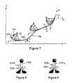
- FIG. 7is a schematic view of a bucket manipulable by a hydraulic machine such as that shown in FIG. 1 and of an undulating trajectory exhibited by an edge of the bucket as the bucket is moved;
- FIG. 8is a perspective view of a lefthand joystick useful for manipulating the bucket in the manner indicated in FIG. 7 ;
- FIG. 9is a perspective view of a righthand joystick useful for manipulating the bucket in the manner indicated in FIG. 7 .
- the inventionuses a simple, approximate, dynamic machine model useful for real-time control applications.
- Some embodiments of the novel control system of the inventionprovide a simple predictive control with embedded system identification.
- the system identificationcan provide real-time identification of actual positions of movable elements of the machine at given points in time.
- the techniquedoes not require pre-calibration or a priori model formulation, although such methods may be employed, if desired.
- the inventionis particularly, although not exclusively, applicable to controlling an articulated hydraulic machine comprising a coordinated joint motion system which coordinated joint motion system includes: a support; multiple links; multiple joints, optionally revolute or prismatic joints, connecting the links one to another and to a support, each joint permitting relative movement between the connected members; multiple actuators to effect the relative movement between the connected members, the multiple actuators being controlled by the coordinate joint control system; and an end effector supported by the jointed links for movement relative to the support.
- the coordinated joint motion systemcan be capable of execution of an automated end effector trajectory without human intervention.
- the coordinated joint control systemcan comprise an operator interface enabling a human supervisor to change the end effector motion or position during execution of the automated trajectory.
- the machine's control systemcan comprise an internal feedback loop to determine a mathematical model of the coordinated joint motion system and provide a model-based forward predictor for directly controlling the joint actuators, optionally by employing a differential control architecture.
- the dynamic machine modelis used in a differential control architecture in which the motion kinematics of the machine is software controlled.
- the control methodretains the advantages of the differential kinematics transformation with which continuous operator control is provided, such as is disclosed and claimed by Danko '404, by controlling transformed actuator velocities.
- closed-loop position controlcan provide for the cancellation of motion error caused by machine inertia, control system-component imperfections, repeatability and other errors.
- the dynamic machine modelcan be continuously updated during motion, providing for adjustments to model errors caused by the approximations inherent in the modeling process.
- Some of these approximationsmay include: the replacement of the true cross-effects between machine links with time dependent adjustments; time-averaging of the model coefficients; the treatment of non-linearity; and approximate solution techniques.
- model space-state identification processapplies least square fit between modeled and measured link positions, resulting in a natural depression of measurement noise. This simple technique does not require any pre-assumption about noise statistics.
- the powered shovel shownto which the control systems and methods of the invention can be applied, which in this case is a front end shovel loader, comprises a tracked motive under carrier or ground-engaging system 101 supporting a variable-slew rotatable turret 102 .
- Rotatable turret 102has a cab 103 to house a human supervisory operator and supports one end of an articulated positioning unit 104 for manipulating a tool or other end effector supported at the other end of positioning unit 104 .
- Positioning unit 104comprises a boom 105 articulated to turret 102 for rotation about a pivot 106 , thereby providing a boom joint.
- Positioning unit 104further comprises a lever arm 108 one end of which is articulated to boom 105 for rotation about a pivot 110 , thereby providing an arm joint.
- the other end of lever arm 108is articulated to and supports a tool, in this case a shovel or bucket 112 , for rotation about a bucket pin 114 , thereby providing a tool joint.
- the described rotationsare to be understood as all being about axes perpendicular to the plane of the paper. While the example illustrated in the drawings comprises revolute joints having one or multiple degrees of freedom, other joints may be utilized, for example prismatic joints.
- the tilt or orientation of shovel 112is preferably also variable, for which purpose shovel 112 can be mounted with two further degrees of rotational freedom about axes in the plane of the paper by means (not shown).
- Such further shovel rotational meansmay comprise, for example, a first pivotal attachment to the distal end of arm 108 providing rotation about a longitudinal arm axis extending through pivots 110 and 114 and a second axis perpendicular thereto, also extending through bucket pin 114 .
- Piston-and-cylinder hydraulic actuators 116 , 118 and 120control the motion and position of boom 105 , arm 108 and shovel or bucket 112 , respectively.
- Each actuator 116 - 120is pivotally secured at its ends and cylinder 120 is connected to shovel 112 through an articulated link 122 to enhance its leverage.
- One or more leveling, guide or ancillary cylinderssuch as leveling cylinder 124 may be provided if desired, but may be rendered unnecessary by the software kinematics configuration capabilities of the present invention.
- actuatorssuch as 126 can optionally also be provided for moving and positioning other elements or systems, for example turret 102 , and ground-engaging system 101 , as will be further described hereinbelow.
- each actuator 116 - 120 and 126is operated by its own, local hydraulic control unit 130 - 136 , respectively, which control unit receives a signal from a joint control coordinator 138 b and controls its associated actuator 116 , 118 , 120 or 126 to provide a suitable output.
- a suitable outputcomprises a desired position and/or velocity of the associated articulated element 104 , 108 , 112 or 128 .
- This outputis determined by the joint control coordinator 138 b based on the forward input from the differential control kinematics generator 138 a and the feedback input from the machine differential kinematics feedback generator 138 c.
- Each articulated element 104 , 108 , 112 or 128is provided with a transducer sensor 141 , 143 , 145 or 147 , respectively, to detect preferably at least the position of the respective articulated element 104 , 108 , 112 or 128 with respect to its supporting element, and report the sensed position, preferably as a continuous or time-divided signal, to the machine differential kinematics feedback generator 138 c.
- a control box 140comprises a suitable number of manually operable control members or joysticks 142 which can be moved, pressured or otherwise manipulated by a human supervisor 144 to move the boom 104 and/or arm 108 and/or shovel 112 , and/or other elements, according to a desired trajectory.
- Joysticks 142may be the same or different and may comprise any convenient and suitable manually operable input member such as a pivotable lever, wheel, slide, key, button or set of keys or buttons or comprise a pointing device such as a mouse, trackball or the like. In mining and construction industries, pivoted levers are common. Conventional powered shovels and other such articulated hydraulic machinery employ at least one joystick for each powered joint. This number may be varied, as will become apparent hereinbelow. Additional joysticks may be provided for operation of rotatable turret 102 and, possibly also for the drive to ground-engaging system 101 to move the powered shovel around, or to or from a work site, or for other desired purposes.
- control box 140The signal outputs from control box 140 are supplied to the differential control kinematics generator 138 a that is provided with suitable data storage means, such as a hard drive, optical drive, flash memory and the like. Suitable software and/or programs, for implementing the control processes may be stored on such data storage means, or may be remotely accessed by central computer 138 .
- the differential control kinematics generator 138 ais also provided with conventional input/output devices such as mouse, keyboard, touch pad or touch screen, monitor, printer data transfer means such as radio wave input/output, removable data storage media, and so on, enabling human supervisor 144 to interface with the unit and mediate the operation of, for example, positioning unit 104 , if desired.
- human supervisor 144Such mediation or intervention by human supervisor 144 enables supervisor 144 to change the response of the control system to one or more inputs received by control box 140 to modify a programmed response or to choose a desired response from multiple possible preprogrammed responses, as will be further described hereinbelow.
- the differential control kinematics generator 138 a , joint control coordinator 138 b , and machine differential kinematics feedback generator 138 care preferably realized in a common central computer 138 .
- the central computer 138provides a visual display which can include schematic representations of the real machine's configuration and virtual machine configurations that can be employed by human supervisor 144 .
- calculated and learned trajectoriescan be made available for selection by human supervisor 144 .
- machine 100may be equipped with cameras providing one or more views of the tool and the work area, which views can be displayed by the computer, and optionally integrated with the control programs to enhance the control system.
- human supervisor 144uses computer 138 to input, or select, a predetermined shovel trajectory for processing by trajectory generator 146 .
- Trajectory generator 146employs a differential time base 148 to generate a differential trajectory with transformation which outputs to differential inverse kinematics model 150 which is generated based on a Jacobian generator 152 .
- Differential inverse kinematics model 150provides a value, series of values or continuous signal for each machine joint to be moved. This may for example be the double differential with respect to time of the particular joint angle ⁇ .
- Joint control system 154can comprise relevant processing components of central computer 138 and control units 130 - 136 . Operation of control units 130 - 136 imparts suitable positioning and velocity to actuators 116 - 120 and 126 , thereby providing a desired machine kinematics configuration 156 to the machine 100 .
- Sensors 141 , 143 , 145 and 147read the positions, and optionally the velocities, of actuators 116 - 120 and 126 which values or signals are applied to Jacobian generator 152 both directly and after forward kinematics processing 158 .
- Human supervisor 144observes the machine, notably the performance of the end effector, in this case, shovel 112 , and also the configuration of the boom 105 and the articulated arm 108 . If desired, supervisor 144 can employ visual feedback 160 to control trajectory generator 146 , or to apply tool trajectory adjustments using joysticks 142 or to select a different or modified trajectory using central computer 138 .
- An optional artificial intelligence component 162receiving input from machine actuators 116 - 120 , 126 and human supervisor 144 , can be used to provide to trajectory generator 146 a desirable or optimum trajectory family for typical, repetitive tasks.
- the term “trajectory”is to be understood to include reference to a series of motion coordinates of an end effector, e.g. a tool or shovel 112 , which represent a number of consecutive motion positions or a locus of the motion of the end effector within a time frame.
- machine kinematicsis to be understood to include reference to the relationship between the actuators' positions or movements and the end effector's position or movement;
- the signal generated by an individual joystick 142can be distributed to more than one actuator 116 - 120 and 126 .
- the distribution of the joystick controlis accomplished dynamically, while the system is in motion, using a pre-programmed trajectory family, or pre-defined coordinate system, or a pre-defined control kinematics.
- position feedback loopsmay optionally be employed for linearization, backlash compensation and/or to achieve added stability.
- Such optional feedback loop in each control elementmay be useful for achieving acceptable control performances when imperfect machine elements are employed.
- the present inventiondescribes one example of an overall, closed feedback control loop for each link that comprises many individual control elements. Others will be apparent to those skilled in the art in the light of this disclosure.
- a particularly useful position-control signalis control velocity. This is a common example characteristic of hydraulic power machinery. Using velocity control, applied by joysticks 142 , the human supervisor 144 can adjust and correct the tool position. An internal feedback loop is applied via sensors 140 - 146 , forward kinematics 158 and Jacobian generator 152 to generate differential inverse kinematics model 150 of the machine configuration for a given tool position. In other words, for a given tool position, a kinematic model is generated of how the machine should be configured, which model specifies parameters such as the angular position and velocity of each joint. As disclosed, the model can be, but is not limited to, an inverse, or pseudo inverse, Jacobian, a sensitivity matrix that relates the joint-space ⁇ variables as a vector, to an input vector of Cartesian variables x i .
- inventive control architecturethere shown is intended to be useful for enhancing or correcting the differential control of a complex system for operating hydraulic machinery that includes imperfect hydraulic valves, actuators, and machine links which have inertia and mechanical inefficiencies causing control response delays and other disturbances.
- the present inventionprovides control system embodiments wherein system processing architecture such as that illustrated in FIGS. 1-3 , is split or cut open into two parts to separately process reference position signals and real time position signals.
- the split signalscan be processed to generate an adjustment or correction for the control system which will better move the end effector on a desired trajectory, and can then be reconnected.
- the illustrated embodiment of the present inventionprovides means to communicate to the control system what may be termed “absolute” position information regarding the movable machine elements or links, as is further described hereinbelow, enabling the end effector position at any given moment to be accurately determined.
- Typical embodiments of the Danko '404 disclosureemploy relative position sensors whose output is not suitable for clear identification in an absolute, ground-related coordinate system of the end effector position at any given moment.
- a control systemgenerates a reference model, which may be a continuously updated model, of what the machine should be doing, and which senses what the machine is actually doing and provides corrections to move the machine toward the model.
- a reference modelwhich may be a continuously updated model, of what the machine should be doing, and which senses what the machine is actually doing and provides corrections to move the machine toward the model.
- the control systememploys model-based forward prediction wherein a next movement of a machine component is predicted and scaled to provide desired movement.
- Velocity-based controlis employed with the expectation that machine components will accurately follow instructions applied to the actuators, possibly with the assistance of embedded, independent correction feedback loops for each component.
- the present inventionprovides, in some embodiments, robust error detection obtained by “looking at” or system-determining the actual or absolute positions of the end effector and the machine links. Desirably, the position of each machine link or element that contributes to movement of the end effector is determined.
- the control systemcan be responsive to one or more of the actual positions.
- One method embodiment of the present inventioncomprises prescribing a desired tool or end effector position to the controlled machine, comparing one or more reference positions appropriate for achieving the desired tool position with one or more actual machine element positions determined from an absolute sensor signal, generating a correction and applying the correction to improve the actual position.
- corrections or adjustmentsare effected kinematically, providing continual incremental adjustments while the machine is moving to execute a specified end effector trajectory.
- the adjustments, or correctionscan be made at system-determined timed intervals.
- the length of the time intervalsmay be selected in accordance with the precision and frequency of position signals output from sensors 141 , 143 , 145 and 147 , the response times of the hydraulic and mechanical machine components, for example, actuators 116 - 120 , 126 , components 105 - 114 and system processing capabilities.
- the system processing time interval for determining the causal, dynamic system modelis 60 ms.
- system processing intervalscan also, or alternatively, be employed.
- samples of the measured position of each link with timeare taken.
- the resulting time series of samplesis evaluated by least square fitting to them a second-order, dynamic motion model, i.e., a differential equation with constant coefficients.
- the constant coefficientsare then used to represent the dynamic machine model for each link.
- kinematic control correctioncan be provided, in accordance with the invention, by determining the actual positions of a hydraulic machine's, or comparable machine's actuators, at a given point in time and comparing those actual actuator positions with reference positions modeled for a hypothetical model machine.
- the hypothetical model machineis under differential coordinated joint motion control, according to Danko '404.
- controlcan be identical to that of the real machine, save for the corrections.
- an objective of the control correction taskis to reduce, minimize or eliminate the difference between [ ⁇ i ref ] and [ ⁇ i ].
- Other embodiments of the inventioncan employ different relationships between [ ⁇ i ref ] and [ ⁇ i ] to obtain other desired objectives. For example, it may be desired to adjust [ ⁇ i ] to obtain a constant or predictably variable relationship to [ ⁇ i ref ].
- a useful reduction, minimization or elimination of the difference between [ ⁇ i ref ] and [ ⁇ i ]can be accomplished by using negative feedback methodology.
- the actual link position vector [ ⁇ i ]can be separated from the reference position vector [ ⁇ i ref ] vector, which is provided as an output signal from suitable system control architecture such as the differential control architecture disclosed and claimed in Danko '404.
- suitable system control architecturesuch as the differential control architecture disclosed and claimed in Danko '404.
- Danko '404discloses the use of transducer sensors 140 - 146 to detect the positions of articulated elements 104 , 108 , 112 and 128 with respect to their supporting elements.
- a dynamic machine modelsuch as model 184 and absolute position sensing.
- the [ ⁇ i ref ] and [ ⁇ i ] vectorscan be actively re-connected using a closing control loop which compares [ ⁇ i ] with [ ⁇ i ref ] and generates a correction signal vector for minimizing, reducing or eliminating the [ ⁇ i ]-[ ⁇ i ref ] difference.
- Other embodiments of the present inventioncan include a dynamic machine motion correction model in the closing control loop.
- This dynamic machine motion correction modelcan process input signals from the position sensors of the machine links, and evaluate those signals to provide an enhanced control signal to actuators 116 - 120 and 126 in order to reduce or minimize the difference between [ ⁇ i ref ] and [ ⁇ i] during motion.
- the machine motion correction modelincluding dynamic machine model 184 and actuator error cancellation module 186 , may incorporate system identification, and an intelligent, predictive control element, if desired.
- this systemadds to the system shown in FIG. 3 a position error correction system comprising a number of modeling components which can be used to provide a reference model against which actual machine performance can be compared, together with an error processing module.
- the added modeling componentscomprise a joint control model 180 , a machine actuators model 182 and a dynamic machine model 184 .
- Error processingis effected by a position and velocity error cancellation module 186 .
- acceleration sensors or accelerometers 190can be provided at or on each of the boom 104 , arm 108 , shovel 112 , other elements 128 and shovel or bucket 112 to monitor the acceleration of its respective host element.
- the inventionincludes embodiments wherein each accelerometer 190 can detect and report acceleration in one dimension, in two dimensions, or in three dimensions, depending upon the host machine element and the application, .i.e. the machine utilized and the operation to be performed. Desirably, acceleration is monitored continuously throughout operation of the machine to execute a trajectory prescribed by the control system and is reported to the control system by wire or wirelessly.
- the sensed accelerationcan be processed locally, at the machine element, or centrally, at the control system to yield an absolute position signal which indicates the position of the respective element in space and time independently of the mechanical condition of the machine element or the machine articulations or joints.
- Accelerometers 190can be mounted on the machine links and can be used as absolute motion sensors, directly providing acceleration signals that can be integrated first to obtain velocities, and subsequently integrated again to obtain absolute positions.
- Sensors 141 - 147 of Dankothat report the position of one moving machine element relative to another machine element which may itself also be moving are not generally suitable for providing precise and reliable position information in the absolute (ground) coordinate system. Mechanical inefficiencies such as machine link elasticity resulting in machine link sag, vibrations and other factors that cannot be detected by typical relative link position sensors are problematic.
- Accelerometers 190 or other suitable sensing or observation meanscan be employed in embodiments of the invention to provide actuator and/or machine element position information relative to a base reference which is fixed in relation to the articulated elements of the machine.
- the base referencecan be the ground or other machine support surface or work surface, for example, a boat deck or ice floe.
- an axis through rotatable turret 102 or ground-engaging system 101 , or other suitable machine componentcould be employed as a reference.
- the absolute position sensors on the machinecan be employed to provide actual, real-world position signals of the articulated machine elements. If desired, a GPS signal can be used to provide, facilitate or supplement the absolute position information.
- joint control model 180employs a differential control signal vector ⁇ dot over ( ⁇ ) ⁇ i u generated by differential inverse kinematics model 150 to provide a model or reference velocity control signal [ ⁇ i ref ] containing velocity information in voltage form for any one or more of actuators 116 - 120 and 126 .
- the velocity informationis calculated to enable the respective actuator 116 - 120 or 126 to operate its associated joint in a manner which will properly assist in moving the end effector along the model reference trajectory.
- Differential control signal vector ⁇ dot over ( ⁇ ) ⁇ i ufrom differential inverse kinematics model 150 , is also supplied to dynamic machine model 184 .
- Machine actuators model 182receives reference velocity control signal [ ⁇ i ref ] from joint control model 180 and employs same to generate a set of one or more reference positions [ ⁇ i ref ] to which one or more actuators 116 - 120 and 126 is to be moved.
- Reference positions [ ⁇ i ref ]may, for example, be the link positions or other element positions of a theoretical perfectly tuned machine with no dynamic response error. Reference positions [ ⁇ i ref ] are output by machine actuators model 182 to dynamic machine model 184 , to error cancellation module 186 , and also to forward kinematics processing 158 and Jacobian generator 152 .
- dynamic machine model 184receives actual link or element positions [ ⁇ i] of the real machine continuously sampled with time. From these or other suitable inputs, dynamic machine model 184 determines a dynamic model of each link of an ideal machine performing a desired trajectory. This model represents dynamic motion observation of each link for a sufficiently long time interval before the actual time instant, and changes with time. In a further embodiment of the invention dynamic machine model 184 provides a logical picture of a desired pattern of movement of relevant machine elements, over time, for performance of a selected end effector trajectory.
- the dynamic machine modelcan include the position, or the velocity of each machine actuator 116 - 120 and 126 , or both the position and the velocity all sampled for a sufficiently long time interval. It will be understood that the control system may of course simply include information indicative of the respective position and/or velocity. If desired, the dynamic model can also or alternatively include position or velocity or position and velocity information for each of the movable components of boom 105 , or other articulated structure, supporting shovel or bucket 112 or another end effector.
- Input into position and velocity error cancellation module 186are both the modeled reference positions [ ⁇ i ref ], from machine actuators model 182 and the actual positions [ ⁇ i] of the real machine. Error cancellation module 186 also receives the modeled input from dynamic machine model 184 . From these several inputs, error cancellation module 186 generates and outputs a differential (velocity) correction signal vector ⁇ dot over ( ⁇ ) ⁇ i c to integrator summator 188 and thence to joint control system 154 .
- error cancellation module 186compares the actual machine element positions [ ⁇ i] with the respective modeled reference positions [ ⁇ i ref ] and calculates suitable corrections or adjustments to the actual or real-world machine link or element positions [ ⁇ i].
- the corrections or adjustmentscan, for example, be selected within the error cancellation module to bring the actual positions [ ⁇ i] into correspondence with, or closer to, the modeled reference positions [ ⁇ i ref ], or effect some other useful adjustment of the actual positions [ ⁇ i].
- Summator 188applies a differential correction signal vector ⁇ dot over ( ⁇ ) ⁇ i c as an adjustment to differential control signal vector ⁇ dot over ( ⁇ ) ⁇ i u received from differential inverse kinematics model 150 , which has been calculated to cause the end effector to follow a trajectory specified in trajectory generator 146 .
- Summator 188effects the adjustment to differential control signal vector ⁇ dot over ( ⁇ ) ⁇ i u for each active one of machine actuators 116 - 120 and 126 .
- the adjusted differential control signal vector ⁇ dot over ( ⁇ ) ⁇ i uis supplied to joint control system 154 which outputs a real machine actuator control signal [ ⁇ i], incorporating the adjustments to machine actuators 116 - 120 and 126 .
- Machine actuators 116 - 120 and 126move their associated movable machine elements, for example, boom 104 , arm 108 , bucket or shovel 112 and/or other elements 128 to have positions and/or velocities which are adjusted compared with what their values would have been without the application of differential correction signal vector ⁇ dot over ( ⁇ ) ⁇ i c to bring the actual end effector trajectory closer to the reference model trajectory, or to effect other desired adjustment.
- link positions signal [ ⁇ i ref ] and control signal [ ⁇ i ref ]are idealized signals that can produce a desired trajectory in a perfectly tuned machine with no dynamic response error.
- dynamic machine model 184is adapted to approximate a given real-world machine, by modifying movement control relative to link positions signal [ ⁇ i ref ] and control signal [ ⁇ i ref ] to approximate a specific host machine. Such modification can be provided by machine learning, artificial intelligence, learning from error correction or in other appropriate manner.
- a benefit of the use of such an adaptive modelis a closer approximation of the model to the actual signals and a reduction in amplitude of the correction vector.
- a still further embodiment of the inventionsupplements any one or more of the above-described embodiments of the invention with an artificial intelligence component such as is referenced “162” in Danko '404 to receive input from machine actuators 116 - 120 , 126 and human supervisor 144 to provide to trajectory generator 146 one or more trajectory families for executing desired tasks, including repetitive tasks.
- an artificial intelligence componentsuch as is referenced “162” in Danko '404 to receive input from machine actuators 116 - 120 , 126 and human supervisor 144 to provide to trajectory generator 146 one or more trajectory families for executing desired tasks, including repetitive tasks.
- human supervisor 144can observe the machine, and provide visual feedback 160 , using joysticks 142 or other suitable input means, to adjust the tool trajectory or to select a different or modified trajectory.
- visual feedbackcan be applied to dynamic machine model 184 to provide an adjusted or re-selected machine model trajectory for reference in generating corrections.
- a hydraulic unit and any link or other members attached or articulated thereto which connects two machine members together across one of the pivots 106 , 110 or 114is referenced as a “link”.
- the spatial configuration of the articulated components of the machinecan be specified in terms of the angular link positions, which may be used to describe, respectively: the angle of boom 105 to turret 102 ; the angle of lever arm 108 to boom 105 ; and the angle of bucket 112 to lever arm 108 .
- Additional angular descriptorsmay optionally include the rotational angle of turret 102 about a vertical axis, called “slew”; the angle of ground-engaging system 101 to the horizontal about a transverse axis (perpendicular to the paper); and, possibly, the angle of ground-engaging system 101 to the horizontal about a direction of travel axis (in the plane of the paper). Further angular descriptors may be employed for additional movable, linked mechanical structure, if desired.
- any or all of such angular position descriptorsmay be included or implicitly referenced in the position vectors, functions or signals referenced herein, for example in reference positions [ ⁇ i ref ], actual machine link positions [ ⁇ i], differential control signal vector ⁇ dot over ( ⁇ ) ⁇ i u , differential correction signal vector ⁇ dot over ( ⁇ ) ⁇ i c , reference actuator control [ ⁇ i ref ] and real machine actuator control signal [ ⁇ i].
- One example of the application of the dynamic model control system of the invention to machine controlimplements the technique on a small excavator having electro-hydraulic valves, link sensors, on-board control computer, and differential control architecture as described herein.
- Kinematics transformationincluding a virtual, revolute-to-Cartesian machine re-configuration and feedback control algorithms can be tested. Test results with such an excavator show that the machine is capable of performing complex tasks according to software-transformed, adjustable kinematics in Cartesian coordinates.
- FIGS. 5 and 6show bucket pin trajectories that can be measured using a camera-based, trajectory tracking method such as is described in Danko et al., “Model-based camera vision evaluation of mining machine motion,” Thirty Second International Symposium of the Application of Computers and Operational Research in the Mineral Industry , Arlington, Ariz., 2005b.
- FIG. 5shows the measured trajectory of the bucket pin during open-loop control operation.
- the test taskis to move the bucket pin along a square at a constant speed. Three consecutive repetitions of the same square target trajectory are made. As shown, the task is executed quite well, considering that the kinematics reconfiguration control works with open-loop hydraulic cylinder velocity control. Repeatability, however, is poor with drifting squares, due to lack of control correction means in the machine's hydraulic elements or an active overall position control. The trajectory can be seen to be somewhat noisy, which noise may largely be attributed to tracking error in the optical measurement.
- FIG. 6shows the bucket pin movement with position error cancellation during motion. Repeatability of the motion trajectory is greatly improved as the overlapping movement paths in FIG. 6 demonstrate the invention's ability to correct error between relative iterations.
- closed-loop controlthe machine retains its good dynamic response. The dynamic response of the machine model is identified, and the model is applied in a predictive mode real-time during machine operation.
- the machine modelwhich is identified over a 60 millisecond, sliding time window in the example, is continuously updated with time every few milliseconds, providing for adjustment to link positions, to cross-effects between links, to non-linear effects, and to the errors caused by the approximations used in the model derivation.
- FIGS. 7-9illustrate a simple operator input device system made possible by the control architecture disclosed in Danko '404 and herein which can provide sophisticated manipulation of a tool such as a shovel or a bucket with only two operator input devices, in this case joysticks.
- FIG. 7illustrates some of the more sophisticated maneuvers that a hydraulically powered bucket or other tool may be called upon to perform.
- a bucket 112is supported on the viewed side by a pivot pin 114 and is pivoted or rotated about pin 114 by a hydraulic actuator, for example shovel rotator 120 (not shown in this figure), coupled to aperture 192 .
- Bucket 112has a leading edge 194 which engages the work material, ground, rock face, bulk deposit or the like.
- Bucket edge 194moves along a trajectory 196 advancing toward the host machine (not shown) with a velocity vt read as a tangent to trajectory 196 .
- the angle of the trajectory tangent to the horizontalis designated “ ⁇ ”.
- Bucket edge 194addresses the work material at a desired cutting angle ⁇ which is measured with respect to the trajectory tangent.
- angle ⁇is selected in the software and remains constant until, or unless, modified by the operator using a joystick as will be further described hereinbelow.
- the proposed bucket steering kinematicswill allow an operator to move the bucket's cutting edge along an arbitrary trajectory using three joystick axes configured to independently control speed, moving direction, and cutting edge angle relative to the movement direction.
- the control system softwarecan be effective to move bucket 112 along a selected trajectory such as 196 without further operator input.
- the operatorcan perform a useful range of adjustments or fine-tuning employing as few as two joysticks, or comparably effective controls, for example as shown in FIGS. 8-9 .
- the control shownwhich is suggested for lefthand use comprises a joystick 198 capable of pivotal movement in two orthogonal, generally horizontal, directions.
- Back-and-forth movementcan be used to control trajectory angle ⁇ , as indicated by arrow 200 .
- Left-to-right movementcan be used to control the slew angle which is the angle of rotation of the turret on the machine base, as indicated by arrow 202 .
- the control shownwhich is suggested for righthand use comprises a joystick 204 also capable of pivotal movement in two orthogonal, generally horizontal, directions.
- Back-and-forth movementcan be used to control the bucket velocity vt along the trajectory 196 , as indicated by arrow 206 .
- Left-to-right movementcan be used to control, or override, the cutting angle ⁇ , as indicated by arrow 208 .
- lefthand and righthand functionscan, of course, be reversed, if desired. It will also be apparent that the functions shown can be assigned differently, if desired, and that different functions may be assigned, and that different input devices can be used to provide more, fewer or different functions, if desired.
- a coordinated system of tool trajectory curvescan be efficiently machine-generated.
- the operatormay work in Cartesian space to effect software-controlled adjustments of the tool velocity, the trajectory angle, the cutting angle, and/or other parameters programmed into the joysticks or other controllers.
- the angle of orientation of a trajectorysuch as the generally square trajectory illustrated in FIG. 6 , or other useful trajectory, to the ground or other work surface may be trimmed so that the tool angle, of bucket or shovel 112 or the like, is a few degrees sharper, e.g. 5° sharper, than the trajectory angle.
- the error-corrected control system of the inventionis useful for controlling a wide range of machinery and comparable equipment, as described in Danko '404, including, by way of example, articulated arm front loaders, mechanical shovels and the like useful for construction, digging, mining, sand, gravel, shale, limestone, ore, and other bulk material handling, open-cast mining, pit mining and the like.
- the inventionincludes such machinery and equipment embodying the novel control systems and methods described herein.
- the notationis changed from ⁇ to x for simplicity.
- a simplified motion equationcan be written as a second-order vector differential equation [ref] between positions x, velocities dx/dt, and accelerations d 2 x/dt 2 :
- D(x), S(x)are n ⁇ n matrices of velocity-proportional drag and position-proportional spring torque coefficients, respectively.
- A(dx/dt, x)is an n-vector, representing an active torque vector, generated by the joint actuators. This term is a function of control signal u, velocity, and position vector variables.
- a first-order, linear approximation(as the first term of the Taylor series) is applied to A:
- a ⁇ ( u , x , d x d t , t )Ju ⁇ ( A ) ⁇ u + Jx ⁇ ( A ) ⁇ x + Jdx ⁇ ( A ) ⁇ d x d t + T ⁇ ( t ) ( 3 )
- T(t)represents a time-dependent torque vector.
- the set of n simultaneous differential equations in Eq (6)defines the simplified dynamic model of an n-link machine.
- alternative methodscan be employed, for example, direct x M signal filtering during model building [Kalman], in the instant example, a simple least-square-fit match is applied:
- simplificationcan be accomplished by de-coupling the set of differential equations and assuming that the cross-effects represented by x i and x j , u j (j ⁇ i) on the left-hand side of Eq (7) are only time-dependent, yet unknown, functions.
- the time-variable coefficients in Eq (6)can be considered time-averaged constants within the sliding [t, t+ ⁇ T] time interval. While more exact solutions may be possible, they are likely to require increased processing resources.
- the decoupled, second-order differential equations with time-averaged coefficients for each link iare:
- the motion control velocity signal u contained in Fcan be assumed to be a response, for example, the output of an electro-hydraulic valve.
- the primary control signalis the input control voltage to the electro-hydraulic valve.
- Such a responseis primarily integrated and/or delayed, and may have linearity and accuracy problems. Accordingly, in this example, these time-variable effects are included in the task of dynamic system identification.
- the equation for u with time-variable constants b and d to be identifiedis:
- Vis the time-variable voltage control signal to the actuator for each link.
- the notationis changed from u to V for simplicity.
- the ⁇ T ⁇ time intervalcan be assumed to be a suitable duration, characterizing the hydraulic system and the electro-hydraulic valve.
- the time variant system identification task for a given machine link at time tis to determine P, A, B, and C time-averaged constants from Eq (15) based on matching x to the measured x M using the optimization condition in Eq (8) for a given ⁇ T time interval.
- Matching x r with the measured x r M values in a least-squares-fit sense over N samplesis equivalent of replacing x r with x r M in Eq (16) and solving for P, A, B,C from an over-determined set of N ⁇ 2 equations (if N>6):
- Eq (16)can be used for numerically solving the time variable position x r from an initial position.
- the dynamic machine modeis applied for a one time-step, forward prediction of the motion of each machine link.
- the efficiency of a model-based, intelligent, adaptive controlis limited.
- the inventionprovides a more efficient solution by employing a simplified system model-component combined with absolute sensory signal contribution.
- a simple method, based on first principles,is developed as an example for extracting a causal, second-order model from noisy, measured system responses.
- fifth or even higher order modelsare routinely expected in hydraulic system applications, as described for example by Walters, R. B., Hydraulic and Electric - Hydraulic Control Systems , Second Enlarged Edition, Kluwer Academic Publishing, Norwell, Mass., 2000, the invention is able, surprisingly, to provide an effective solution using low-order, but nevertheless time-variant, model application.
- the present inventionincludes machines and mechanical systems equipped with the novel control systems described herein as well as methods of operation of machines and mechanical systems which employ the novel control methods disclosed herein.
Landscapes
- Engineering & Computer Science (AREA)
- General Engineering & Computer Science (AREA)
- Structural Engineering (AREA)
- Mining & Mineral Resources (AREA)
- Civil Engineering (AREA)
- Artificial Intelligence (AREA)
- Health & Medical Sciences (AREA)
- Computer Vision & Pattern Recognition (AREA)
- Evolutionary Computation (AREA)
- Medical Informatics (AREA)
- Software Systems (AREA)
- Physics & Mathematics (AREA)
- General Physics & Mathematics (AREA)
- Automation & Control Theory (AREA)
- Mechanical Engineering (AREA)
- Robotics (AREA)
- Operation Control Of Excavators (AREA)
Abstract
Description
- a) compares the actual end effector position at a given point in time with a reference position appropriate for the desired end effector trajectory;
- b) generates a difference between the actual end effector position and the reference position; and
- c) applies a correction signal to the machine to reduce the difference.
where the new constants are:
Claims (17)
Priority Applications (5)
| Application Number | Priority Date | Filing Date | Title |
|---|---|---|---|
| US11/333,994US8065060B2 (en) | 2006-01-18 | 2006-01-18 | Coordinated joint motion control system with position error correction |
| CA002573654ACA2573654A1 (en) | 2006-01-18 | 2007-01-09 | Coordinated joint motion control system with position error correction |
| US13/271,774US20120029663A1 (en) | 2006-01-18 | 2011-10-12 | Coordinated joint motion control system with position error correction |
| US14/105,044US20140107832A1 (en) | 2006-01-18 | 2013-12-12 | Coordinated joint motion control system with position error correction |
| US14/798,254US9304501B2 (en) | 2006-01-18 | 2015-07-13 | Coordinated joint motion control system with position error correction |
Applications Claiming Priority (1)
| Application Number | Priority Date | Filing Date | Title |
|---|---|---|---|
| US11/333,994US8065060B2 (en) | 2006-01-18 | 2006-01-18 | Coordinated joint motion control system with position error correction |
Related Child Applications (1)
| Application Number | Title | Priority Date | Filing Date |
|---|---|---|---|
| US13/271,774DivisionUS20120029663A1 (en) | 2006-01-18 | 2011-10-12 | Coordinated joint motion control system with position error correction |
Publications (2)
| Publication Number | Publication Date |
|---|---|
| US20070168100A1 US20070168100A1 (en) | 2007-07-19 |
| US8065060B2true US8065060B2 (en) | 2011-11-22 |
Family
ID=38264297
Family Applications (4)
| Application Number | Title | Priority Date | Filing Date |
|---|---|---|---|
| US11/333,994Expired - Fee RelatedUS8065060B2 (en) | 2006-01-18 | 2006-01-18 | Coordinated joint motion control system with position error correction |
| US13/271,774AbandonedUS20120029663A1 (en) | 2006-01-18 | 2011-10-12 | Coordinated joint motion control system with position error correction |
| US14/105,044AbandonedUS20140107832A1 (en) | 2006-01-18 | 2013-12-12 | Coordinated joint motion control system with position error correction |
| US14/798,254Expired - Fee RelatedUS9304501B2 (en) | 2006-01-18 | 2015-07-13 | Coordinated joint motion control system with position error correction |
Family Applications After (3)
| Application Number | Title | Priority Date | Filing Date |
|---|---|---|---|
| US13/271,774AbandonedUS20120029663A1 (en) | 2006-01-18 | 2011-10-12 | Coordinated joint motion control system with position error correction |
| US14/105,044AbandonedUS20140107832A1 (en) | 2006-01-18 | 2013-12-12 | Coordinated joint motion control system with position error correction |
| US14/798,254Expired - Fee RelatedUS9304501B2 (en) | 2006-01-18 | 2015-07-13 | Coordinated joint motion control system with position error correction |
Country Status (2)
| Country | Link |
|---|---|
| US (4) | US8065060B2 (en) |
| CA (1) | CA2573654A1 (en) |
Cited By (26)
| Publication number | Priority date | Publication date | Assignee | Title |
|---|---|---|---|---|
| US20080201043A1 (en)* | 2007-02-21 | 2008-08-21 | Mark Peter Sahlin | Automated control of boom and attachment for work vehicle |
| US20100051439A1 (en)* | 2006-09-05 | 2010-03-04 | Bosch Rexroth D.S.I. | Handle for the remote control of a moving vehicle, particularly a civil engineering works vehicle, an agricultural or handling vehicle |
| US20100312437A1 (en)* | 2008-02-20 | 2010-12-09 | Komatsu Ltd. | Construction machine |
| US20110022407A1 (en)* | 2008-01-07 | 2011-01-27 | Lorenz Bewig | Method for error recognition in a control system of a medical treatment and/or diagnosis device |
| US20110318157A1 (en)* | 2009-03-06 | 2011-12-29 | Komatsu Ltd. | Construction Machine, Method for Controlling Construction Machine, and Program for Causing Computer to Execute the Method |
| US20120130599A1 (en)* | 2010-11-18 | 2012-05-24 | Caterpillar Inc. | Control system for a machine |
| US20130085645A1 (en)* | 2011-09-30 | 2013-04-04 | Komatsu Ltd. | Blade control system and construction machine |
| US20140025205A1 (en)* | 2012-07-20 | 2014-01-23 | Seiko Epson Corporation | Control system, program, and method of controlling mechanical equipment |
| US8644964B2 (en)* | 2012-05-03 | 2014-02-04 | Deere & Company | Method and system for controlling movement of an end effector on a machine |
| US20150227653A1 (en)* | 2014-02-07 | 2015-08-13 | Canon Kabushiki Kaisha | Dynamics calculation method, program and recording medium |
| US9304501B2 (en) | 2006-01-18 | 2016-04-05 | Board Of Regents Of The Nevada System Of Higher Education, On Behalf Of The University Of Nevada, Reno | Coordinated joint motion control system with position error correction |
| US9562341B2 (en) | 2015-04-24 | 2017-02-07 | Harnischfeger Technologies, Inc. | Dipper drop detection and mitigation in an industrial machine |
| US20170089043A1 (en)* | 2015-09-25 | 2017-03-30 | Caterpillar Inc. | Online system identification for controlling a machine |
| US9752336B2 (en) | 2016-02-09 | 2017-09-05 | Caterpillar Inc. | Systems and methods for controlling an implement of a machine utilizing an orientation leveling system |
| US9969084B2 (en) | 2001-08-31 | 2018-05-15 | Board Of Regents Of The Nevada System Of Higher Education, On Behalf Of The University Of Nevada, Reno | Coordinated joint motion control system |
| US20190017248A1 (en)* | 2016-03-31 | 2019-01-17 | Sumitomo Heavy Industries, Ltd. | Excavator |
| US10459462B2 (en)* | 2017-06-21 | 2019-10-29 | Caterpillar Inc. | Sensor fusion feedback for controlling fluid pressures in a machine |
| US10494788B2 (en) | 2016-11-02 | 2019-12-03 | Clark Equipment Company | System and method for defining a zone of operation for a lift arm |
| US10774574B2 (en) | 2018-03-26 | 2020-09-15 | Honda Motor Co., Ltd. | Operation of vehicle power doors |
| US20210025133A1 (en)* | 2019-07-26 | 2021-01-28 | Deere & Company | Anticipatory modification of machine settings based on predicted operational state transition |
| US11168458B2 (en)* | 2017-02-20 | 2021-11-09 | Komatsu Ltd. | Work vehicle and method of controlling work vehicle |
| US11267129B2 (en)* | 2018-11-30 | 2022-03-08 | Metal Industries Research & Development Centre | Automatic positioning method and automatic control device |
| US11279026B2 (en)* | 2013-11-01 | 2022-03-22 | Brain Corporation | Reduced degree of freedom robotic controller apparatus and methods |
| US11385139B2 (en) | 2018-11-21 | 2022-07-12 | Martin E. Best | Active backlash detection methods and systems |
| US11451419B2 (en) | 2019-03-15 | 2022-09-20 | The Research Foundation for the State University | Integrating volterra series model and deep neural networks to equalize nonlinear power amplifiers |
| US20230287660A1 (en)* | 2020-09-28 | 2023-09-14 | Nec Corporation | Work control method, work control system, work control apparatus, and non-transitory computer readable medium storing work control program |
Families Citing this family (78)
| Publication number | Priority date | Publication date | Assignee | Title |
|---|---|---|---|---|
| WO2007086783A1 (en)* | 2006-01-26 | 2007-08-02 | Volvo Construction Equipment Ab | A method for controlling a movement of a vehicle component |
| WO2007146984A2 (en)* | 2006-06-13 | 2007-12-21 | Intuitive Surgical, Inc. | Control system configured to compensate for non-ideal actuator-to-joint linkage characteristics in a medical robotic system |
| US9746329B2 (en)* | 2006-11-08 | 2017-08-29 | Caterpillar Trimble Control Technologies Llc | Systems and methods for augmenting an inertial navigation system |
| US8065037B2 (en)* | 2007-08-07 | 2011-11-22 | Board Of Regents Of The Nevada System Of Higher Education, On Behalf Of The University Of Nevada, Reno | Control method and system for hydraulic machines employing a dynamic joint motion model |
| US8135518B2 (en) | 2007-09-28 | 2012-03-13 | Caterpillar Inc. | Linkage control system with position estimator backup |
| WO2009043369A1 (en)* | 2007-10-01 | 2009-04-09 | Abb Technology Ab | A method for controlling a plurality of axes in an industrial robot system and an industrial robot system |
| US20090192644A1 (en)* | 2008-01-30 | 2009-07-30 | Meyer Thomas J | Method and system for manufacturing an article using portable hand-held tools |
| US8392075B2 (en)* | 2008-02-25 | 2013-03-05 | Clark Equipment Company | Carrier and backhoe control system and method |
| FR2928387B1 (en)* | 2008-03-10 | 2012-11-16 | Westline | METHOD AND SYSTEM FOR AUTOMATIC CALIBRATION OF EARTHMOVING MACHINERY |
| SE537181C2 (en)* | 2008-10-21 | 2015-02-24 | Svab Hydraulik Ab | Control system and procedure for a tiltrotator |
| CN102245841A (en)* | 2008-11-26 | 2011-11-16 | 沃尔沃建筑设备公司 | Method for calibrating an angle sensor and vehicle with an angle sensor |
| DE102010001829B4 (en)* | 2010-02-11 | 2011-09-01 | Siemens Aktiengesellschaft | Method for moving a machine element of a machine from automation technology and drive system |
| WO2011162561A2 (en)* | 2010-06-23 | 2011-12-29 | 두산인프라코어 주식회사 | Apparatus and method for controlling work trajectory of construction equipment |
| US8977440B2 (en) | 2010-09-09 | 2015-03-10 | Robert Bosch Gmbh | Body movement mitigation in earth-moving vehicles |
| US20120253609A1 (en)* | 2011-03-31 | 2012-10-04 | Caterpillar Inc. | Proportional control using state space based scheduling |
| AU2012202213B2 (en) | 2011-04-14 | 2014-11-27 | Joy Global Surface Mining Inc | Swing automation for rope shovel |
| US8620536B2 (en)* | 2011-04-29 | 2013-12-31 | Harnischfeger Technologies, Inc. | Controlling a digging operation of an industrial machine |
| US8560183B2 (en)* | 2011-04-29 | 2013-10-15 | Harnischfeger Technologies, Inc. | Controlling a digging operation of an industrial machine |
| US9464410B2 (en)* | 2011-05-19 | 2016-10-11 | Deere & Company | Collaborative vehicle control using both human operator and automated controller input |
| PL3199752T3 (en) | 2011-08-03 | 2019-05-31 | Joy Global Underground Mining Llc | Automated operations of a mining machine |
| CN102331745B (en)* | 2011-09-20 | 2013-01-09 | 中达电通股份有限公司 | Bag making machine control system using bus-type motion controller and control method thereof |
| US8860352B2 (en)* | 2012-05-10 | 2014-10-14 | Mitsubishi Electric Research Laboratories, Inc. | System and method for controlling actuators |
| JP5529241B2 (en)* | 2012-11-20 | 2014-06-25 | 株式会社小松製作所 | Work machine and method for measuring work amount of work machine |
| WO2014123253A1 (en)* | 2013-02-06 | 2014-08-14 | Volvo Construction Equipment Ab | Swing control system for construction machines |
| JP6284302B2 (en)* | 2013-04-02 | 2018-02-28 | 株式会社タダノ | Boom telescopic pattern selection device |
| AU2015200234B2 (en) | 2014-01-21 | 2019-02-28 | Joy Global Surface Mining Inc | Controlling a crowd parameter of an industrial machine |
| WO2015109392A1 (en)* | 2014-01-24 | 2015-07-30 | Atlas Copco Rock Drills Ab | Autonomous loading vehicle controller |
| US9238899B2 (en)* | 2014-03-27 | 2016-01-19 | Kubota Corporation | Front loader |
| US9822507B2 (en)* | 2014-12-02 | 2017-11-21 | Cnh Industrial America Llc | Work vehicle with enhanced implement position control and bi-directional self-leveling functionality |
| JP6314105B2 (en)* | 2015-03-05 | 2018-04-18 | 株式会社日立製作所 | Trajectory generator and work machine |
| WO2016161444A1 (en)* | 2015-04-03 | 2016-10-06 | Think Surgical, Inc. | Robotic system with intuitive motion control |
| DE102015108473A1 (en)* | 2015-05-28 | 2016-12-01 | Schwing Gmbh | Large manipulator with quick folding and unfolding articulated mast |
| DE102016104358B4 (en)* | 2016-03-10 | 2019-11-07 | Manitowoc Crane Group France Sas | Method for determining the carrying capacity of a crane and crane |
| CN106225790B (en)* | 2016-07-13 | 2018-11-02 | 百度在线网络技术(北京)有限公司 | A kind of determination method and device of unmanned vehicle positioning accuracy |
| ES2899284T3 (en)* | 2016-07-15 | 2022-03-10 | Fastbrick Ip Pty Ltd | Vehicle incorporating a brick laying machine |
| US20180110190A1 (en)* | 2016-10-20 | 2018-04-26 | Deere & Company | Work vehicle gyroscopic boom control system and method |
| CN109944843B (en)* | 2016-11-22 | 2021-01-05 | 北京航空航天大学 | Robot hydraulic drive rotates joint closed-loop control system |
| US10329741B2 (en)* | 2016-12-20 | 2019-06-25 | Caterpillar Trimble Control Technologies Llc | Excavator control architecture for generating sensor location and offset angle |
| JP6360583B1 (en)* | 2017-03-29 | 2018-07-18 | 大成建設株式会社 | Machine learning device for construction machine, construction machine and machine learning method for construction machine |
| CN107553496B (en)* | 2017-09-29 | 2020-09-22 | 南京阿凡达机器人科技有限公司 | Method and device for determining and correcting errors of inverse kinematics solving method of mechanical arm |
| CN107825427B (en)* | 2017-11-30 | 2021-07-09 | 马鞍山钢铁股份有限公司 | A method for controlling the clamping arm of a hacksaw machine |
| CN108044623B (en)* | 2017-12-07 | 2021-01-01 | 河南广播电视大学 | Mechanical arm linkage control method and system based on single-chip microcomputer training |
| CN108107728B (en)* | 2017-12-15 | 2021-02-12 | 南京理工大学 | Electro-hydraulic position servo system control method based on interference compensation |
| US10738439B2 (en) | 2018-01-19 | 2020-08-11 | Deere & Company | Open loop electrohydraulic bucket position control method and system |
| EP3531062A1 (en) | 2018-02-26 | 2019-08-28 | Renishaw PLC | Coordinate positioning machine |
| US10689831B2 (en)* | 2018-03-27 | 2020-06-23 | Deere & Company | Converting mobile machines into high precision robots |
| US11162241B2 (en) | 2018-03-27 | 2021-11-02 | Deere & Company | Controlling mobile machines with a robotic attachment |
| US10870968B2 (en)* | 2018-04-30 | 2020-12-22 | Deere & Company | Work vehicle control system providing coordinated control of actuators |
| DK201870355A1 (en) | 2018-06-01 | 2019-12-16 | Apple Inc. | Virtual assistant operation in multi-device environments |
| CN109848983B (en)* | 2018-12-10 | 2020-07-28 | 华中科技大学 | A method for highly compliant human-guided robots to work together |
| CN109623827B (en)* | 2019-01-21 | 2023-04-07 | 兰州大学 | High-performance redundant manipulator repetitive motion planning method and device |
| JP7728632B2 (en)* | 2019-02-01 | 2025-08-25 | 株式会社小松製作所 | CONSTRUCTION MACHINE CONTROL SYSTEM, CONSTRUCTION MACHINE, AND CONSTRUCTION MACHINE CONTROL METHOD |
| JP7283910B2 (en)* | 2019-02-01 | 2023-05-30 | 株式会社小松製作所 | CONSTRUCTION MACHINE CONTROL SYSTEM, CONSTRUCTION MACHINE, AND CONSTRUCTION MACHINE CONTROL METHOD |
| JP7197392B2 (en)* | 2019-02-01 | 2022-12-27 | 株式会社小松製作所 | CONSTRUCTION MACHINE CONTROL SYSTEM, CONSTRUCTION MACHINE, AND CONSTRUCTION MACHINE CONTROL METHOD |
| US20220195704A1 (en)* | 2019-04-04 | 2022-06-23 | Komatsu Ltd. | System including work machine, computer implemented method, method for producing trained posture estimation model, and training data |
| IT201900005234A1 (en)* | 2019-04-05 | 2020-10-05 | Cnh Ind Italia Spa | Control method for carrying out a combined movement of an arm and an implement in an operating machine, corresponding control system and operating machine comprising such control system |
| US20210087777A1 (en)* | 2019-09-25 | 2021-03-25 | Deere & Company | Work implement linkage system having automated features for a work vehicle |
| CN113021330B (en)* | 2019-12-24 | 2022-04-05 | 沈阳智能机器人创新中心有限公司 | A Multi-robot Synchronous Follow-up Control Method in a Distributed Network |
| CN111409069B (en)* | 2020-03-18 | 2022-04-19 | 中国科学技术大学 | A kinematic velocity solution method for a rope-pulled parallel robot with variable structure |
| JPWO2021241487A1 (en)* | 2020-05-25 | 2021-12-02 | ||
| CN111753374B (en)* | 2020-06-26 | 2023-08-25 | 北京百度网讯科技有限公司 | Speed determination method, device, equipment and computer storage medium |
| US12017352B2 (en)* | 2020-10-29 | 2024-06-25 | Nvidia Corporation | Transformation of joint space coordinates using machine learning |
| US20230399812A1 (en)* | 2020-11-09 | 2023-12-14 | Hiroshima University | Autonomous driving device for work machine |
| CN112549022A (en)* | 2020-11-19 | 2021-03-26 | 珠海格力电器股份有限公司 | Method and device for determining spatial position, robot, storage medium and processor |
| US20220195689A1 (en)* | 2020-12-18 | 2022-06-23 | Regents Of The University Of Minnesota | End Effector Position Estimation |
| CN112632803A (en)* | 2021-01-12 | 2021-04-09 | 四川大学 | Tracking control method and device, electronic equipment and storage medium |
| CN113103225B (en)* | 2021-03-03 | 2022-06-10 | 重庆大学 | A multi-stage stable autonomous docking method for mobile robots based on image measurement |
| US12210335B2 (en)* | 2021-06-03 | 2025-01-28 | Intrinsic Innovation Llc | Workcell modeling using motion profile matching and swept profile matching |
| CN114571448A (en)* | 2021-12-30 | 2022-06-03 | 广州铁路职业技术学院(广州铁路机械学校) | Joint-limited pseudo-inverse repetitive motion planning method for redundant manipulator |
| IT202200000293A1 (en)* | 2022-01-11 | 2023-07-11 | Cnh Ind Italia Spa | WORK VEHICLE |
| CN114326378B (en)* | 2022-01-27 | 2023-12-05 | 三一重机有限公司 | Method and device for controlling track of working machine and working machine |
| CN114541502B (en)* | 2022-02-21 | 2023-01-10 | 北京合众鼎新信息技术有限公司 | Control method of valve-controlled hydraulic cylinder and automatic control system of bulldozer blade |
| CN116677025A (en)* | 2022-02-23 | 2023-09-01 | 北京百度网讯科技有限公司 | Control method and control device for excavating machine |
| CN114779632B (en)* | 2022-03-24 | 2025-01-24 | 重庆大学 | A trajectory tracking control method for a life support robot system |
| AU2024214049A1 (en)* | 2023-02-03 | 2025-08-14 | Rigid Robotics Inc. | Systems for obtaining a work tool spatial position and the methods thereon |
| CN116079738B (en)* | 2023-02-24 | 2024-08-20 | 中国民用航空飞行学院 | Vision-guided industrial robot system calibration method |
| CN119526395A (en)* | 2024-11-25 | 2025-02-28 | 电子科技大学 | A robust model predictive control method for trajectory tracking control of a robotic arm |
| CN120065757B (en)* | 2025-04-28 | 2025-08-12 | 济南职业学院 | Mobile robot track tracking control method and system |
Citations (63)
| Publication number | Priority date | Publication date | Assignee | Title |
|---|---|---|---|---|
| US4156835A (en) | 1974-05-29 | 1979-05-29 | Massachusetts Institute Of Technology | Servo-controlled mobility device |
| US4243923A (en) | 1979-01-22 | 1981-01-06 | Massachusetts Institute Of Technology | Servo-controlled mobility device |
| US4763276A (en) | 1986-03-21 | 1988-08-09 | Actel Partnership | Methods for refining original robot command signals |
| US4771389A (en)* | 1985-04-26 | 1988-09-13 | Nissan Motor Co., Ltd. | Control method and unit for controlling a manipulator |
| US4773025A (en)* | 1986-11-20 | 1988-09-20 | Unimation, Inc. | Multiaxis robot control having curve fitted path control |
| US4829418A (en)* | 1987-04-24 | 1989-05-09 | Laser Alignment, Inc. | Apparatus and method for controlling a hydraulic excavator |
| US4889466A (en)* | 1985-07-26 | 1989-12-26 | Kabushiki Kaisha Komatsu Seisakusho | Control device for a power shovel |
| US4893254A (en) | 1988-04-20 | 1990-01-09 | University Of British Columbia | Manipulator arm position sensing |
| US4937759A (en) | 1986-02-18 | 1990-06-26 | Robotics Research Corporation | Industrial robot with controller |
| US4973215A (en) | 1986-02-18 | 1990-11-27 | Robotics Research Corporation | Industrial robot with servo |
| US4975856A (en) | 1986-02-18 | 1990-12-04 | Robotics Research Corporation | Motion controller for redundant or nonredundant linkages |
| US4999553A (en) | 1989-12-28 | 1991-03-12 | The United States Of America As Represented By The Administrator Of The National Aeronautics And Space Administration | Method and apparatus for configuration control of redundant robots |
| US5155423A (en) | 1986-02-18 | 1992-10-13 | Robotics Research Corporation | Industrial robot with servo |
| US5160239A (en)* | 1988-09-08 | 1992-11-03 | Caterpillar Inc. | Coordinated control for a work implement |
| US5224033A (en) | 1989-09-26 | 1993-06-29 | Kabushiki Kaisha Komatsu Seisakusho | Work automation apparatus for hydraulic drive machines |
| US5257177A (en)* | 1990-09-29 | 1993-10-26 | Danfoss A/S | Apparatus for controlling the movement of hydraulically movable work equipment and a path control arrangement |
| US5294873A (en) | 1992-10-27 | 1994-03-15 | The United States Of America As Represented By The Administrator Of The National Aeronautics And Space Administration | Kinematic functions for redundancy resolution using configuration control |
| US5341459A (en) | 1991-05-09 | 1994-08-23 | The United States Of America As Represented By The Administrator Of The National Aeronautics And Space Administration | Generalized compliant motion primitive |
| US5341289A (en) | 1992-06-25 | 1994-08-23 | United Parcel Service Of America, Inc. | Method for controlling three degree of freedom actuator system |
| US5363304A (en)* | 1991-01-23 | 1994-11-08 | Shin Caterpillar Mitsubishi, Ltd. | Method for controlling a hydraulic excavator |
| US5390104A (en) | 1990-04-02 | 1995-02-14 | Fulton; Francis M. | Adaptive control man-augmentation system for a suspended work station |
| US5404661A (en)* | 1994-05-10 | 1995-04-11 | Caterpillar Inc. | Method and apparatus for determining the location of a work implement |
| US5408767A (en)* | 1992-07-09 | 1995-04-25 | Kabushiki Kaisha Kobe Seiko Sho | Excavation controlling apparatus for dipper shovel |
| US5430643A (en) | 1992-03-11 | 1995-07-04 | The United States Of America As Represented By The Administrator Of The National Aeronautics And Space Administration | Configuration control of seven degree of freedom arms |
| US5446981A (en)* | 1991-10-29 | 1995-09-05 | Kabushiki Kaisha Komatsu Seisakusho | Method of selecting automatic operation mode of working machine |
| US5528843A (en)* | 1994-08-18 | 1996-06-25 | Caterpillar Inc. | Control system for automatically controlling a work implement of an earthworking machine to capture material |
| US5550953A (en) | 1994-04-20 | 1996-08-27 | The United States Of America As Represented By The Administrator Of The National Aeronautics And Space Administration | On-line method and apparatus for coordinated mobility and manipulation of mobile robots |
| US5737500A (en) | 1992-03-11 | 1998-04-07 | California Institute Of Technology | Mobile dexterous siren degree of freedom robot arm with real-time control system |
| US5767648A (en)* | 1996-04-19 | 1998-06-16 | Massachusetts Institute Of Technology | Base force/torque sensor apparatus for the precise control of manipulators with joint friction and a method of use thereof |
| US5831875A (en)* | 1995-11-07 | 1998-11-03 | Fujitsu Limited | Link mechanism analyzer and link mechanism joint data arithmetic apparatus |
| US5854988A (en)* | 1996-06-05 | 1998-12-29 | Topcon Laser Systems, Inc. | Method for controlling an excavator |
| US5903988A (en)* | 1993-12-24 | 1999-05-18 | Komatsu Ltd. | Control device for use in a working machine having three or more arms for controlling path of movement of a tool mounted on one of the arms |
| US5953838A (en)* | 1997-07-30 | 1999-09-21 | Laser Alignment, Inc. | Control for hydraulically operated construction machine having multiple tandem articulated members |
| US5968104A (en)* | 1996-06-26 | 1999-10-19 | Hitachi Construction Machinery Co., Ltd. | Front control system for construction machine |
| US6047227A (en)* | 1996-11-19 | 2000-04-04 | Caterpillar Inc. | Method and apparatus for operating geography altering machinery relative to a work site |
| US6061617A (en)* | 1997-10-21 | 2000-05-09 | Case Corporation | Adaptable controller for work vehicle attachments |
| US6076030A (en)* | 1998-10-14 | 2000-06-13 | Carnegie Mellon University | Learning system and method for optimizing control of autonomous earthmoving machinery |
| US6140787A (en)* | 1997-07-23 | 2000-10-31 | Rsi Technologies Ltd. | Method and apparatus for controlling a work implement |
| US6144910A (en)* | 1996-10-23 | 2000-11-07 | New Holland North America, Inc. | Vehicle control apparatus and method |
| US6208925B1 (en)* | 1999-04-26 | 2001-03-27 | Caterpillar Inc. | Simplified powertrain load prediction method and system using computer based models |
| US6211471B1 (en)* | 1999-01-27 | 2001-04-03 | Caterpillar Inc. | Control system for automatically controlling a work implement of an earthmoving machine to capture, lift and dump material |
| US6233511B1 (en)* | 1997-11-26 | 2001-05-15 | Case Corporation | Electronic control for a two-axis work implement |
| US6317669B1 (en)* | 1999-10-28 | 2001-11-13 | Hitachi Construction Machinery Co. Ltd. | Automatically operated shovel |
| US6327517B1 (en) | 2000-07-27 | 2001-12-04 | Applied Materials, Inc. | Apparatus for on-the-fly center finding and notch aligning for wafer handling robots |
| US6336067B1 (en)* | 1998-08-12 | 2002-01-01 | Hitachi Construction Machinery Co., Ltd. | Electronic control system and control device for construction machine |
| US20030001751A1 (en)* | 2000-11-17 | 2003-01-02 | Hiroshi Ogura | Display device and display controller of construction machinery |
| US6609315B1 (en)* | 2002-10-31 | 2003-08-26 | Deere & Company | Automatic backhoe tool orientation control |
| US6655465B2 (en)* | 2001-03-16 | 2003-12-02 | David S. Carlson | Blade control apparatuses and methods for an earth-moving machine |
| US6691437B1 (en)* | 2003-03-24 | 2004-02-17 | Trimble Navigation Limited | Laser reference system for excavating machine |
| US6826450B2 (en)* | 2001-04-16 | 2004-11-30 | Fanuc Ltd. | Robot controller |
| US20040267404A1 (en)* | 2001-08-31 | 2004-12-30 | George Danko | Coordinated joint motion control system |
| US20050004734A1 (en)* | 2003-07-03 | 2005-01-06 | Cripps Donald Lewis | Method and system for controlling a mechanical arm |
| US20050049838A1 (en)* | 2001-12-31 | 2005-03-03 | George Danko | Multiphase physical transport modeling method and modeling system |
| US6891526B2 (en) | 2000-06-19 | 2005-05-10 | Deutsches Zentrum für Luft- und Raumfahrt e.V. | Input device for commanding control operations of a real and virtual object |
| US6898502B2 (en)* | 2000-03-31 | 2005-05-24 | Hitachi Construction Machinery Co., Ltd. | System for changing function of work machine and base station |
| US7010367B2 (en)* | 2003-10-16 | 2006-03-07 | Caterpillar Inc. | Operator interface for a work machine |
| US7114430B2 (en)* | 2004-09-30 | 2006-10-03 | Caterpillar Inc. | Adaptive position determining system for hydraulic cylinder |
| US20060245896A1 (en)* | 2005-03-31 | 2006-11-02 | Caterpillar Inc. | Automatic digging and loading system for a work machine |
| US7139662B2 (en)* | 1997-11-28 | 2006-11-21 | Trimble Ab | Device and method for determining the position of a working part |
| US20070255454A1 (en) | 2006-04-27 | 2007-11-01 | Honda Motor Co., Ltd. | Control Of Robots From Human Motion Descriptors |
| US7295891B2 (en)* | 2002-11-06 | 2007-11-13 | Kuka Roboter Gmbh | Method and device for controlling movements in the case of manipulators |
| US7797860B2 (en)* | 2007-04-30 | 2010-09-21 | Deere & Company | Automated control of boom or attachment for work vehicle to a preset position |
| US7853356B2 (en)* | 2006-04-14 | 2010-12-14 | Fanuc Robotics America, Inc. | Method for optimizing a robot program and a robot system |
Family Cites Families (17)
| Publication number | Priority date | Publication date | Assignee | Title |
|---|---|---|---|---|
| JPH0683976B2 (en) | 1988-03-15 | 1994-10-26 | インターナシヨナル・ビジネス・マシーンズ・コーポレーシヨン | Compliance control method |
| US4891767A (en) | 1988-06-02 | 1990-01-02 | Combustion Engineering, Inc. | Machine vision system for position sensing |
| US5159249A (en) | 1989-05-16 | 1992-10-27 | Dalila Megherbi | Method and apparatus for controlling robot motion at and near singularities and for robot mechanical design |
| US5062264A (en) | 1990-07-24 | 1991-11-05 | The University Of British Columbia | Hydraulic control system |
| US5167121A (en) | 1991-06-25 | 1992-12-01 | University Of British Columbia | Proportional hydraulic control |
| US5784542A (en) | 1995-09-07 | 1998-07-21 | California Institute Of Technology | Decoupled six degree-of-freedom teleoperated robot system |
| US5710870A (en) | 1995-09-07 | 1998-01-20 | California Institute Of Technology | Decoupled six degree-of-freedom robot manipulator |
| DE10164496A1 (en)* | 2001-12-28 | 2003-07-17 | Siemens Ag | automation system |
| US8467904B2 (en)* | 2005-12-22 | 2013-06-18 | Honda Motor Co., Ltd. | Reconstruction, retargetting, tracking, and estimation of pose of articulated systems |
| US7859540B2 (en)* | 2005-12-22 | 2010-12-28 | Honda Motor Co., Ltd. | Reconstruction, retargetting, tracking, and estimation of motion for articulated systems |
| US8065060B2 (en)* | 2006-01-18 | 2011-11-22 | The Board Of Regents Of The University And Community College System On Behalf Of The University Of Nevada | Coordinated joint motion control system with position error correction |
| US8065037B2 (en)* | 2007-08-07 | 2011-11-22 | Board Of Regents Of The Nevada System Of Higher Education, On Behalf Of The University Of Nevada, Reno | Control method and system for hydraulic machines employing a dynamic joint motion model |
| CA2735262C (en)* | 2007-08-28 | 2016-10-11 | The University Of Surrey | Inverse kinematics |
| US8135518B2 (en)* | 2007-09-28 | 2012-03-13 | Caterpillar Inc. | Linkage control system with position estimator backup |
| US8204623B1 (en)* | 2009-02-13 | 2012-06-19 | Hrl Laboratories, Llc | Planning approach for obstacle avoidance in complex environment using articulated redundant robot arm |
| US8527158B2 (en)* | 2010-11-18 | 2013-09-03 | Caterpillar Inc. | Control system for a machine |
| JP6284302B2 (en)* | 2013-04-02 | 2018-02-28 | 株式会社タダノ | Boom telescopic pattern selection device |
- 2006
- 2006-01-18USUS11/333,994patent/US8065060B2/ennot_activeExpired - Fee Related
- 2007
- 2007-01-09CACA002573654Apatent/CA2573654A1/ennot_activeAbandoned
- 2011
- 2011-10-12USUS13/271,774patent/US20120029663A1/ennot_activeAbandoned
- 2013
- 2013-12-12USUS14/105,044patent/US20140107832A1/ennot_activeAbandoned
- 2015
- 2015-07-13USUS14/798,254patent/US9304501B2/ennot_activeExpired - Fee Related
Patent Citations (67)
| Publication number | Priority date | Publication date | Assignee | Title |
|---|---|---|---|---|
| US4156835A (en) | 1974-05-29 | 1979-05-29 | Massachusetts Institute Of Technology | Servo-controlled mobility device |
| US4243923A (en) | 1979-01-22 | 1981-01-06 | Massachusetts Institute Of Technology | Servo-controlled mobility device |
| US4771389A (en)* | 1985-04-26 | 1988-09-13 | Nissan Motor Co., Ltd. | Control method and unit for controlling a manipulator |
| US4889466A (en)* | 1985-07-26 | 1989-12-26 | Kabushiki Kaisha Komatsu Seisakusho | Control device for a power shovel |
| US5155423A (en) | 1986-02-18 | 1992-10-13 | Robotics Research Corporation | Industrial robot with servo |
| US5581166A (en) | 1986-02-18 | 1996-12-03 | Robotics Research Corporation | Industrial robot with servo |
| US4937759A (en) | 1986-02-18 | 1990-06-26 | Robotics Research Corporation | Industrial robot with controller |
| US4973215A (en) | 1986-02-18 | 1990-11-27 | Robotics Research Corporation | Industrial robot with servo |
| US4975856A (en) | 1986-02-18 | 1990-12-04 | Robotics Research Corporation | Motion controller for redundant or nonredundant linkages |
| US4763276A (en) | 1986-03-21 | 1988-08-09 | Actel Partnership | Methods for refining original robot command signals |
| US4773025A (en)* | 1986-11-20 | 1988-09-20 | Unimation, Inc. | Multiaxis robot control having curve fitted path control |
| US4829418A (en)* | 1987-04-24 | 1989-05-09 | Laser Alignment, Inc. | Apparatus and method for controlling a hydraulic excavator |
| US4893254A (en) | 1988-04-20 | 1990-01-09 | University Of British Columbia | Manipulator arm position sensing |
| US5160239A (en)* | 1988-09-08 | 1992-11-03 | Caterpillar Inc. | Coordinated control for a work implement |
| US5224033A (en) | 1989-09-26 | 1993-06-29 | Kabushiki Kaisha Komatsu Seisakusho | Work automation apparatus for hydraulic drive machines |
| US4999553A (en) | 1989-12-28 | 1991-03-12 | The United States Of America As Represented By The Administrator Of The National Aeronautics And Space Administration | Method and apparatus for configuration control of redundant robots |
| US5390104A (en) | 1990-04-02 | 1995-02-14 | Fulton; Francis M. | Adaptive control man-augmentation system for a suspended work station |
| US5257177A (en)* | 1990-09-29 | 1993-10-26 | Danfoss A/S | Apparatus for controlling the movement of hydraulically movable work equipment and a path control arrangement |
| US5363304A (en)* | 1991-01-23 | 1994-11-08 | Shin Caterpillar Mitsubishi, Ltd. | Method for controlling a hydraulic excavator |
| US5341459A (en) | 1991-05-09 | 1994-08-23 | The United States Of America As Represented By The Administrator Of The National Aeronautics And Space Administration | Generalized compliant motion primitive |
| US5446981A (en)* | 1991-10-29 | 1995-09-05 | Kabushiki Kaisha Komatsu Seisakusho | Method of selecting automatic operation mode of working machine |
| US5430643A (en) | 1992-03-11 | 1995-07-04 | The United States Of America As Represented By The Administrator Of The National Aeronautics And Space Administration | Configuration control of seven degree of freedom arms |
| US5737500A (en) | 1992-03-11 | 1998-04-07 | California Institute Of Technology | Mobile dexterous siren degree of freedom robot arm with real-time control system |
| US5341289A (en) | 1992-06-25 | 1994-08-23 | United Parcel Service Of America, Inc. | Method for controlling three degree of freedom actuator system |
| US5408767A (en)* | 1992-07-09 | 1995-04-25 | Kabushiki Kaisha Kobe Seiko Sho | Excavation controlling apparatus for dipper shovel |
| US5294873A (en) | 1992-10-27 | 1994-03-15 | The United States Of America As Represented By The Administrator Of The National Aeronautics And Space Administration | Kinematic functions for redundancy resolution using configuration control |
| US5903988A (en)* | 1993-12-24 | 1999-05-18 | Komatsu Ltd. | Control device for use in a working machine having three or more arms for controlling path of movement of a tool mounted on one of the arms |
| US5550953A (en) | 1994-04-20 | 1996-08-27 | The United States Of America As Represented By The Administrator Of The National Aeronautics And Space Administration | On-line method and apparatus for coordinated mobility and manipulation of mobile robots |
| US5404661A (en)* | 1994-05-10 | 1995-04-11 | Caterpillar Inc. | Method and apparatus for determining the location of a work implement |
| US5528843A (en)* | 1994-08-18 | 1996-06-25 | Caterpillar Inc. | Control system for automatically controlling a work implement of an earthworking machine to capture material |
| US5831875A (en)* | 1995-11-07 | 1998-11-03 | Fujitsu Limited | Link mechanism analyzer and link mechanism joint data arithmetic apparatus |
| US5767648A (en)* | 1996-04-19 | 1998-06-16 | Massachusetts Institute Of Technology | Base force/torque sensor apparatus for the precise control of manipulators with joint friction and a method of use thereof |
| US5854988A (en)* | 1996-06-05 | 1998-12-29 | Topcon Laser Systems, Inc. | Method for controlling an excavator |
| US5968104A (en)* | 1996-06-26 | 1999-10-19 | Hitachi Construction Machinery Co., Ltd. | Front control system for construction machine |
| US6144910A (en)* | 1996-10-23 | 2000-11-07 | New Holland North America, Inc. | Vehicle control apparatus and method |
| US6047227A (en)* | 1996-11-19 | 2000-04-04 | Caterpillar Inc. | Method and apparatus for operating geography altering machinery relative to a work site |
| US6140787A (en)* | 1997-07-23 | 2000-10-31 | Rsi Technologies Ltd. | Method and apparatus for controlling a work implement |
| US5953838A (en)* | 1997-07-30 | 1999-09-21 | Laser Alignment, Inc. | Control for hydraulically operated construction machine having multiple tandem articulated members |
| US6061617A (en)* | 1997-10-21 | 2000-05-09 | Case Corporation | Adaptable controller for work vehicle attachments |
| US6233511B1 (en)* | 1997-11-26 | 2001-05-15 | Case Corporation | Electronic control for a two-axis work implement |
| US7139662B2 (en)* | 1997-11-28 | 2006-11-21 | Trimble Ab | Device and method for determining the position of a working part |
| US6336067B1 (en)* | 1998-08-12 | 2002-01-01 | Hitachi Construction Machinery Co., Ltd. | Electronic control system and control device for construction machine |
| US6076030A (en)* | 1998-10-14 | 2000-06-13 | Carnegie Mellon University | Learning system and method for optimizing control of autonomous earthmoving machinery |
| US6211471B1 (en)* | 1999-01-27 | 2001-04-03 | Caterpillar Inc. | Control system for automatically controlling a work implement of an earthmoving machine to capture, lift and dump material |
| US6208925B1 (en)* | 1999-04-26 | 2001-03-27 | Caterpillar Inc. | Simplified powertrain load prediction method and system using computer based models |
| US6317669B1 (en)* | 1999-10-28 | 2001-11-13 | Hitachi Construction Machinery Co. Ltd. | Automatically operated shovel |
| US6898502B2 (en)* | 2000-03-31 | 2005-05-24 | Hitachi Construction Machinery Co., Ltd. | System for changing function of work machine and base station |
| US6891526B2 (en) | 2000-06-19 | 2005-05-10 | Deutsches Zentrum für Luft- und Raumfahrt e.V. | Input device for commanding control operations of a real and virtual object |
| US6327517B1 (en) | 2000-07-27 | 2001-12-04 | Applied Materials, Inc. | Apparatus for on-the-fly center finding and notch aligning for wafer handling robots |
| US20030001751A1 (en)* | 2000-11-17 | 2003-01-02 | Hiroshi Ogura | Display device and display controller of construction machinery |
| US6655465B2 (en)* | 2001-03-16 | 2003-12-02 | David S. Carlson | Blade control apparatuses and methods for an earth-moving machine |
| US6826450B2 (en)* | 2001-04-16 | 2004-11-30 | Fanuc Ltd. | Robot controller |
| US20040267404A1 (en)* | 2001-08-31 | 2004-12-30 | George Danko | Coordinated joint motion control system |
| US20090099738A1 (en) | 2001-08-31 | 2009-04-16 | George Danko | Coordinated joint motion control system |
| US7457698B2 (en) | 2001-08-31 | 2008-11-25 | The Board Of Regents Of The University And Community College System On Behalf Of The University Of Nevada, Reno | Coordinated joint motion control system |
| US20050049838A1 (en)* | 2001-12-31 | 2005-03-03 | George Danko | Multiphase physical transport modeling method and modeling system |
| US6609315B1 (en)* | 2002-10-31 | 2003-08-26 | Deere & Company | Automatic backhoe tool orientation control |
| US7295891B2 (en)* | 2002-11-06 | 2007-11-13 | Kuka Roboter Gmbh | Method and device for controlling movements in the case of manipulators |
| US6691437B1 (en)* | 2003-03-24 | 2004-02-17 | Trimble Navigation Limited | Laser reference system for excavating machine |
| US6968264B2 (en)* | 2003-07-03 | 2005-11-22 | Deere & Company | Method and system for controlling a mechanical arm |
| US20050004734A1 (en)* | 2003-07-03 | 2005-01-06 | Cripps Donald Lewis | Method and system for controlling a mechanical arm |
| US7010367B2 (en)* | 2003-10-16 | 2006-03-07 | Caterpillar Inc. | Operator interface for a work machine |
| US7114430B2 (en)* | 2004-09-30 | 2006-10-03 | Caterpillar Inc. | Adaptive position determining system for hydraulic cylinder |
| US20060245896A1 (en)* | 2005-03-31 | 2006-11-02 | Caterpillar Inc. | Automatic digging and loading system for a work machine |
| US7853356B2 (en)* | 2006-04-14 | 2010-12-14 | Fanuc Robotics America, Inc. | Method for optimizing a robot program and a robot system |
| US20070255454A1 (en) | 2006-04-27 | 2007-11-01 | Honda Motor Co., Ltd. | Control Of Robots From Human Motion Descriptors |
| US7797860B2 (en)* | 2007-04-30 | 2010-09-21 | Deere & Company | Automated control of boom or attachment for work vehicle to a preset position |
Non-Patent Citations (20)
| Title |
|---|
| Alami et al., "An Architecture for Autonomy," The International Journal of Robotics Research, vol. 17, No. 4, 40 pp. (Apr. 1998). |
| Brooks, "Model-Based Three-Directional Interpretations of Two-Dimensional Images," IEEE Transactions on Pattern Analysis and Machine Intelligence, vol. PAMI-5, No. 2, pp. 140-150 (Mar. 1983). |
| Craig, Introduction to Robotics: Mechanics and Control, Table of Contents, Ch. 3, "Manipulator Kinematics," Ch. 4, "Inverse Manipular Kinematics," Ch. 5, "Jacobians: Velocities and Static Forces," and Ch. 6, "Manipulator Dynamics," 142 pp. (1989). |
| Danko et al., "Model-based camera vision evaluation of mining machine motion," 32nd Intl Symp. of the Application of Computers and Operations Research in the Mineral Industry, pp. 513-520 (Mar. 2005). |
| Danko, "Operator Control Architecture," 4th Regional Symp. On Computer Applications in the Minerals Industries, 15 pp. (Sep. 2001). |
| Danko, source code listings and other materials associated with graduate course entitled, "Introduction to Robotics," taught at the University of Technology, Helsinki, Finland, 81 pp. (2000). |
| Goodzeit et al., "System and Periodic Disturbance Identification for Feedforward-Feedback Control of Flexible Spacecraft," Proc. of the 35th AIAA Aerospace Science meeting and Exhibit, 17 pp. (Jan. 1997). |
| International Search Report for PCT US02/27860 dated Feb. 26, 2003, 1 page. |
| Juang et al., "Identification of System, Observer, and Controller from Closed-loop Experimental Data," Journal of Guidance, Control, and Dynamics, vol. 17, No. 2 pp. 9196 (Jan.-Feb. 1994). |
| Kalman et al., "A New Approach to Linear Filtering and Prediction Problems," Transactions of the ASME-Journal of Basic Engineering, vol. 82 (Series D), pp. 35-45 (1960). |
| Kogler et al., "Further approaches in automation on roadheaders/bolter miners in production and development," Fourth Intl Symp. on Mine Mechanization and Automation, pp. A6-11 through A6-18 (1997). |
| Lu et al. "Fast and Globally Convergent Pose Estimation from Video Images," IEEE Transactions on Pattern Analysis and Machine Intelligence, vol. 22, No. 6, pp. 610-622 (Jun. 2000). |
| Phan et al., "Improvement of Observer/Kalman Filter Identification (OKID) by Residual Whitening," Journal of Vibrations and Acoustics, vol. 117, pp. 232-239 (Apr. 1995). |
| Phan et al., "Markov Parameters in System Identification: Old and New Concepts," Structronic Systems: Smart Structures, Devices, and Systems, vol. 2, pp. 263-293 (1997). |
| Phan et al., "Unifying Input-Output and State-Space Perspectives of Predictive Control," Princeton University, Dept. of Mechanical and Aerospace Engineering Technical Report No. 3044, 35 pp. (Sep. 1998). |
| Roberts et al., "Automation of Underground Truck Haulage," Intl Symp. on Mine Mechanisation and Automation, pp. B5-23 through B5-32 (Jul. 1997). |
| Schetzen, The Volterra and Wiener Theories of Nonlinear Systems, Table of Contents, Ch. 2, "First-Order (Linear) Systems," and Ch. 15, "Nonlinear System Identification," 60 pp. (1980). |
| Shafiq et al., "Marker detection and trajectory generation algorithms for a multicamera based gait analysis system," Mechatronics, vol. 11, pp. 409-437 (2001). |
| Stentz et al., "A Robotic Excavator for Autonomous Truck Loading," Autonomous Robots, vol. 7, No. 2, pp. 175-186 (Sep. 1999). |
| Walters, Hydraulic and Electric-Hydraulic Control Systems, Table of Contents, Ch. 8, "Control Systems," Ch. 12, "System Analysis of Electro-hydraulic Control Systems," Ch. 16, "Further Case Studies," Ch. 21, "System Enhancement," and Ch. 27, "Steady-State System Analysis," 76 pp.(2000). |
Cited By (45)
| Publication number | Priority date | Publication date | Assignee | Title |
|---|---|---|---|---|
| US9969084B2 (en) | 2001-08-31 | 2018-05-15 | Board Of Regents Of The Nevada System Of Higher Education, On Behalf Of The University Of Nevada, Reno | Coordinated joint motion control system |
| US9304501B2 (en) | 2006-01-18 | 2016-04-05 | Board Of Regents Of The Nevada System Of Higher Education, On Behalf Of The University Of Nevada, Reno | Coordinated joint motion control system with position error correction |
| US20100051439A1 (en)* | 2006-09-05 | 2010-03-04 | Bosch Rexroth D.S.I. | Handle for the remote control of a moving vehicle, particularly a civil engineering works vehicle, an agricultural or handling vehicle |
| US20090018729A1 (en)* | 2007-02-21 | 2009-01-15 | Mark Peter Sahlin | Automated control of boom and attachment for work vehicle |
| US20090018728A1 (en)* | 2007-02-21 | 2009-01-15 | Mark Peter Sahlin | Automated control of boom and attachment for work vehicle |
| US20080201043A1 (en)* | 2007-02-21 | 2008-08-21 | Mark Peter Sahlin | Automated control of boom and attachment for work vehicle |
| US8200398B2 (en) | 2007-02-21 | 2012-06-12 | Deere & Company | Automated control of boom and attachment for work vehicle |
| US8204653B2 (en) | 2007-02-21 | 2012-06-19 | Deere & Company | Automated control of boom and attachment for work vehicle |
| US8386133B2 (en) | 2007-02-21 | 2013-02-26 | Deere & Company | Automated control of boom and attachment for work vehicle |
| US20110022407A1 (en)* | 2008-01-07 | 2011-01-27 | Lorenz Bewig | Method for error recognition in a control system of a medical treatment and/or diagnosis device |
| US9619619B2 (en)* | 2008-01-07 | 2017-04-11 | Siemens Aktiengesellschaft | Method for error recognition in a control system of a medical treatment and/or diagnosis device |
| US20100312437A1 (en)* | 2008-02-20 | 2010-12-09 | Komatsu Ltd. | Construction machine |
| US9109345B2 (en)* | 2009-03-06 | 2015-08-18 | Komatsu Ltd. | Construction machine, method for controlling construction machine, and program for causing computer to execute the method |
| US20110318157A1 (en)* | 2009-03-06 | 2011-12-29 | Komatsu Ltd. | Construction Machine, Method for Controlling Construction Machine, and Program for Causing Computer to Execute the Method |
| US8527158B2 (en)* | 2010-11-18 | 2013-09-03 | Caterpillar Inc. | Control system for a machine |
| US20120130599A1 (en)* | 2010-11-18 | 2012-05-24 | Caterpillar Inc. | Control system for a machine |
| US20140151074A1 (en)* | 2011-09-30 | 2014-06-05 | Komatsu Ltd. | Blade control system and construction machine |
| US9200426B2 (en)* | 2011-09-30 | 2015-12-01 | Komatsu Ltd. | Blade control system and construction machine |
| US20130085645A1 (en)* | 2011-09-30 | 2013-04-04 | Komatsu Ltd. | Blade control system and construction machine |
| US8731784B2 (en)* | 2011-09-30 | 2014-05-20 | Komatsu Ltd. | Blade control system and construction machine |
| US8644964B2 (en)* | 2012-05-03 | 2014-02-04 | Deere & Company | Method and system for controlling movement of an end effector on a machine |
| US20140025205A1 (en)* | 2012-07-20 | 2014-01-23 | Seiko Epson Corporation | Control system, program, and method of controlling mechanical equipment |
| US9149930B2 (en)* | 2012-07-20 | 2015-10-06 | Seiko Epson Corporation | Control system, program, and method of controlling mechanical equipment |
| US11279026B2 (en)* | 2013-11-01 | 2022-03-22 | Brain Corporation | Reduced degree of freedom robotic controller apparatus and methods |
| US20150227653A1 (en)* | 2014-02-07 | 2015-08-13 | Canon Kabushiki Kaisha | Dynamics calculation method, program and recording medium |
| US10394969B2 (en)* | 2014-02-07 | 2019-08-27 | Canon Kabushiki Kaisha | Dynamics calculation method, program and recording medium |
| US9562341B2 (en) | 2015-04-24 | 2017-02-07 | Harnischfeger Technologies, Inc. | Dipper drop detection and mitigation in an industrial machine |
| US20170089043A1 (en)* | 2015-09-25 | 2017-03-30 | Caterpillar Inc. | Online system identification for controlling a machine |
| US9752336B2 (en) | 2016-02-09 | 2017-09-05 | Caterpillar Inc. | Systems and methods for controlling an implement of a machine utilizing an orientation leveling system |
| US10858808B2 (en)* | 2016-03-31 | 2020-12-08 | Sumitomo Heavy Industries, Ltd. | Excavator |
| US20190017248A1 (en)* | 2016-03-31 | 2019-01-17 | Sumitomo Heavy Industries, Ltd. | Excavator |
| US10494788B2 (en) | 2016-11-02 | 2019-12-03 | Clark Equipment Company | System and method for defining a zone of operation for a lift arm |
| US11168458B2 (en)* | 2017-02-20 | 2021-11-09 | Komatsu Ltd. | Work vehicle and method of controlling work vehicle |
| US10459462B2 (en)* | 2017-06-21 | 2019-10-29 | Caterpillar Inc. | Sensor fusion feedback for controlling fluid pressures in a machine |
| US10774574B2 (en) | 2018-03-26 | 2020-09-15 | Honda Motor Co., Ltd. | Operation of vehicle power doors |
| US11385139B2 (en) | 2018-11-21 | 2022-07-12 | Martin E. Best | Active backlash detection methods and systems |
| US11906397B2 (en) | 2018-11-21 | 2024-02-20 | Martin E. Best | Active backlash detection methods and systems |
| US11267129B2 (en)* | 2018-11-30 | 2022-03-08 | Metal Industries Research & Development Centre | Automatic positioning method and automatic control device |
| US11451419B2 (en) | 2019-03-15 | 2022-09-20 | The Research Foundation for the State University | Integrating volterra series model and deep neural networks to equalize nonlinear power amplifiers |
| US11855813B2 (en) | 2019-03-15 | 2023-12-26 | The Research Foundation For Suny | Integrating volterra series model and deep neural networks to equalize nonlinear power amplifiers |
| US12273221B2 (en) | 2019-03-15 | 2025-04-08 | The Research Foundation For The State University Of New York | Integrating Volterra series model and deep neural networks to equalize nonlinear power amplifiers |
| US11697917B2 (en)* | 2019-07-26 | 2023-07-11 | Deere & Company | Anticipatory modification of machine settings based on predicted operational state transition |
| US20210025133A1 (en)* | 2019-07-26 | 2021-01-28 | Deere & Company | Anticipatory modification of machine settings based on predicted operational state transition |
| US20230287660A1 (en)* | 2020-09-28 | 2023-09-14 | Nec Corporation | Work control method, work control system, work control apparatus, and non-transitory computer readable medium storing work control program |
| US12366056B2 (en)* | 2020-09-28 | 2025-07-22 | Nec Corporation | Work control method, work control system, work control apparatus, and non-transitory computer readable medium storing work control program |
Also Published As
| Publication number | Publication date |
|---|---|
| US20150322647A1 (en) | 2015-11-12 |
| CA2573654A1 (en) | 2007-07-18 |
| US20120029663A1 (en) | 2012-02-02 |
| US20140107832A1 (en) | 2014-04-17 |
| US20070168100A1 (en) | 2007-07-19 |
| US9304501B2 (en) | 2016-04-05 |
Similar Documents
| Publication | Publication Date | Title |
|---|---|---|
| US8065060B2 (en) | Coordinated joint motion control system with position error correction | |
| US9969084B2 (en) | Coordinated joint motion control system | |
| Egli et al. | A general approach for the automation of hydraulic excavator arms using reinforcement learning | |
| Ha et al. | Robotic excavation in construction automation | |
| US20210215483A1 (en) | Controlling movement of a machine using sensor fusion | |
| Egli et al. | Towards RL-based hydraulic excavator automation | |
| US5908458A (en) | Automated system and method for control of movement using parameterized scripts | |
| US6076030A (en) | Learning system and method for optimizing control of autonomous earthmoving machinery | |
| JPH11247231A (en) | Software architecture for autonomous control of earth-moving machine | |
| Heikkilä et al. | Development of an earthmoving machinery autonomous excavator development platform | |
| Chacko et al. | State of the art in excavators | |
| Groll et al. | Autonomous trenching with hierarchically organized primitives | |
| Gu et al. | Proportional‐Integral‐Plus control of an intelligent excavator | |
| Shao et al. | Automatic excavation planning of hydraulic excavator | |
| JP7328918B2 (en) | working machine | |
| Zweiri et al. | Modelling and control of an unmanned excavator vehicle | |
| Althoefer et al. | Hybrid soil parameter measurement and estimation scheme for excavation automation | |
| Ishihara et al. | Automated Loading Operation for Mass-Production Hydraulic Excavators by Nonlinear Model Predictive Control | |
| Patel et al. | Dynamics of mini hydraulic backhoe excavator: A lagrange-euler (le) approach | |
| Maeda et al. | Improving operational space control of heavy manipulators via open-loop compensation | |
| Chen et al. | Modeling and control of general hydraulic excavator for human-in-the-loop automation | |
| Jeon et al. | Automating motor grader leveling operations: Kinematic analysis for blade pose control | |
| Lertcomepeesin et al. | Study of Autnomous Pond Excavation in Real Environment | |
| Endo et al. | Path tracking of bucket edge using a hydraulic excavator with a built-in angular velocity controller | |
| Park et al. | Model-Based Control of Automatic Excavator Using Kinematic Models of Operation Part |
Legal Events
| Date | Code | Title | Description |
|---|---|---|---|
| AS | Assignment | Owner name:THE BOARD OF REGENTS OF THE UNIVERSITY AND COMMUNI Free format text:ASSIGNMENT OF ASSIGNORS INTEREST;ASSIGNOR:DANKO, GEORGE;REEL/FRAME:017592/0868 Effective date:20060420 | |
| STCF | Information on status: patent grant | Free format text:PATENTED CASE | |
| AS | Assignment | Owner name:ENERGY, UNITED STATES DEPARTMENT OF, DISTRICT OF C Free format text:CONFIRMATORY LICENSE;ASSIGNOR:UNIVERSITY OF NEVADA, RENO;REEL/FRAME:027395/0865 Effective date:20080530 | |
| FPAY | Fee payment | Year of fee payment:4 | |
| AS | Assignment | Owner name:BOARD OF REGENTS OF THE NEVADA SYSTEM OF HIGHER ED Free format text:CHANGE OF NAME;ASSIGNOR:BOARD OF REGENTS OF THE UNIVERSITY AND COMMUNITY COLLEGE SYSTEM ON BEHALF OF THE UNIVERSITY OF NEVADA;REEL/FRAME:037019/0240 Effective date:20050518 | |
| AS | Assignment | Owner name:UNITED STATES DEPARTMENT OF ENERGY, DISTRICT OF CO Free format text:CONFIRMATORY LICENSE;ASSIGNOR:UNIVERSITY OF NEVADA RENO;REEL/FRAME:045969/0881 Effective date:20060530 | |
| FEPP | Fee payment procedure | Free format text:MAINTENANCE FEE REMINDER MAILED (ORIGINAL EVENT CODE: REM.); ENTITY STATUS OF PATENT OWNER: SMALL ENTITY | |
| LAPS | Lapse for failure to pay maintenance fees | Free format text:PATENT EXPIRED FOR FAILURE TO PAY MAINTENANCE FEES (ORIGINAL EVENT CODE: EXP.); ENTITY STATUS OF PATENT OWNER: SMALL ENTITY | |
| STCH | Information on status: patent discontinuation | Free format text:PATENT EXPIRED DUE TO NONPAYMENT OF MAINTENANCE FEES UNDER 37 CFR 1.362 | |
| FP | Lapsed due to failure to pay maintenance fee | Effective date:20191122 |