US8064839B2 - Method and apparatus for co-location of two radio frequency devices - Google Patents
Method and apparatus for co-location of two radio frequency devicesDownload PDFInfo
- Publication number
- US8064839B2 US8064839B2US12/758,403US75840310AUS8064839B2US 8064839 B2US8064839 B2US 8064839B2US 75840310 AUS75840310 AUS 75840310AUS 8064839 B2US8064839 B2US 8064839B2
- Authority
- US
- United States
- Prior art keywords
- communication interface
- bluetooth
- bus
- frequency
- range
- Prior art date
- Legal status (The legal status is an assumption and is not a legal conclusion. Google has not performed a legal analysis and makes no representation as to the accuracy of the status listed.)
- Expired - Fee Related
Links
- 238000000034methodMethods0.000titleclaimsabstractdescription50
- 238000004891communicationMethods0.000claimsabstractdescription64
- 238000012545processingMethods0.000claimsdescription7
- 230000004044responseEffects0.000claimsdescription5
- 238000010586diagramMethods0.000description15
- 230000005540biological transmissionEffects0.000description11
- 238000005516engineering processMethods0.000description11
- 238000001228spectrumMethods0.000description6
- 230000008859changeEffects0.000description4
- 230000000644propagated effectEffects0.000description4
- 230000000694effectsEffects0.000description3
- 238000004590computer programMethods0.000description2
- 238000013500data storageMethods0.000description2
- 230000003287optical effectEffects0.000description2
- 230000001902propagating effectEffects0.000description2
- 235000008694Humulus lupulusNutrition0.000description1
- 230000008867communication pathwayEffects0.000description1
- 230000000295complement effectEffects0.000description1
- 230000000593degrading effectEffects0.000description1
- 230000000977initiatory effectEffects0.000description1
- 230000002452interceptive effectEffects0.000description1
- 238000007726management methodMethods0.000description1
- 238000013507mappingMethods0.000description1
- 238000012986modificationMethods0.000description1
- 230000004048modificationEffects0.000description1
- 230000006855networkingEffects0.000description1
- 230000037361pathwayEffects0.000description1
- 230000002093peripheral effectEffects0.000description1
- 230000009467reductionEffects0.000description1
- 230000032258transportEffects0.000description1
Images


Classifications
- H—ELECTRICITY
- H04—ELECTRIC COMMUNICATION TECHNIQUE
- H04B—TRANSMISSION
- H04B15/00—Suppression or limitation of noise or interference
- H—ELECTRICITY
- H04—ELECTRIC COMMUNICATION TECHNIQUE
- H04B—TRANSMISSION
- H04B1/00—Details of transmission systems, not covered by a single one of groups H04B3/00 - H04B13/00; Details of transmission systems not characterised by the medium used for transmission
- H04B1/38—Transceivers, i.e. devices in which transmitter and receiver form a structural unit and in which at least one part is used for functions of transmitting and receiving
- H04B1/40—Circuits
- H—ELECTRICITY
- H04—ELECTRIC COMMUNICATION TECHNIQUE
- H04W—WIRELESS COMMUNICATION NETWORKS
- H04W16/00—Network planning, e.g. coverage or traffic planning tools; Network deployment, e.g. resource partitioning or cells structures
- H04W16/14—Spectrum sharing arrangements between different networks
- H—ELECTRICITY
- H04—ELECTRIC COMMUNICATION TECHNIQUE
- H04B—TRANSMISSION
- H04B2215/00—Reducing interference at the transmission system level
- H04B2215/064—Reduction of clock or synthesizer reference frequency harmonics
- H04B2215/068—Reduction of clock or synthesizer reference frequency harmonics by avoiding a reception frequency range
- H—ELECTRICITY
- H04—ELECTRIC COMMUNICATION TECHNIQUE
- H04W—WIRELESS COMMUNICATION NETWORKS
- H04W88/00—Devices specially adapted for wireless communication networks, e.g. terminals, base stations or access point devices
- H04W88/02—Terminal devices
- H04W88/06—Terminal devices adapted for operation in multiple networks or having at least two operational modes, e.g. multi-mode terminals
Definitions
- the present inventionrelates generally to wireless communication between devices and more particularly to locating two radio frequency (RF) devices that share the same RF band in a common apparatus where the two co-located devices communicate with each other so that transmissions can occur simultaneously without substantial interference.
- RFradio frequency
- Bluetoothis a short range radio technology operating in the license-free Industrial, Scientific and Medical (ISM) frequency band between the frequencies of about 2400 Mega Hertz (MHz) to about 2483.5 MHz.
- ISMIndustrial, Scientific and Medical
- Bluetoothwas to replace cables which connect devices such as mobile phone handsets, headsets, and portable computers.
- the promise of the Bluetooth technologyhas since grown to enabling wireless communications between any electrical device.
- WPANwireless personal area network
- WLANwireless local area networking
- IEEEInstitute of Electrical and Electronics Engineers 802.11b
- a WLANis an extension or replacement of wired networks for numerous computing devices.
- a laptop that is WLAN enabledcan connect to a particular network through an access point.
- WLAN technologyis being embraced by businesses.
- Bluetooth technology directed towards individuals and WLAN technology directed toward businessesthe two technologies are complementary. Therefore, a portable device, such as a portable computer, mobile phone, personal digital assistant (PDA), etc., may contain both a WLAN RF device and a Bluetooth RF device.
- the co-located RF devicesmust co-exist without interfering with each other.
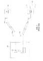
- FIG. 1illustrates a schematic diagram of portable computer 100 containing Bluetooth RF device 102 and WLAN RF device 110 also known as Institute of Electrical and Electronics Engineers (IEEE) standard 802.11b.
- Bluetooth RF device 102is in communication with antenna 104 .
- a wireless communication pathwayis established between Bluetooth RF device 102 and Bluetooth device 106 from antenna 104 to antenna 108 .
- Bluetooth device 106can be any number of electronic devices, such as a PDA, mobile phone, keyboard, mouse, speakers, etc.
- Portable computer 100also includes 802.11b RF device for wireless access to a local area network (LAN).
- 802.11b RF deviceis in communication with antenna 112 and establishes a link with access point 114 through antenna 116 .
- Access point 114provides access to LAN 118 through an Ethernet connection.
- the transmission technique used by the RF devices of FIG. 1is a spread spectrum technique.
- Two spread spectrum modulation techniquesare commonly used by devices transmitting in the ISM band.
- One of the modulation techniquesfrequency-hopping spread spectrum (FHSS)
- FHSSfrequency-hopping spread spectrum
- Bluetooth enabled devicesUnder FHSS, a device can transmit high energy in a relatively narrow band for a limited time.
- the Bluetooth standarduses channels of 1 MHz in width at a hop rate of approximately 1600 times per second. There are 79 different channels used by the Bluetooth standard in the ISM frequency band.
- FHSS devices, such as Bluetooth enabled devicesare changing, i.e., hopping, channels according to a mapping algorithm following a different sequence depending on the link control state.
- the second modulation techniqueis typically used by IEEE 802.11b.
- DSSSdirect-sequence spread spectrum
- IEEE 802.11buses a 22 MHz passband to transmit data.
- the 802.11b standardcan utilize any of eleven 22 MHz subchannels across the ISM frequency band.
- FIG. 2illustrates a schematic diagram of the overlap between a DSSS passband and the Bluetooth time slots.
- Bluetoothis a time division multiplexed (TDM) system where the basic unit of operation is a dwell period of 625 microseconds ( ⁇ s) duration during which transmission between Bluetooth devices occurs as represented by transmission slots 122 .
- DSSS packet 124is shown overlapping three transmission slots 122 .
- the Bluetooth devicemay not capture the frequency the 802.11b device transmits at.
- the Bluetooth devicedoes not have the capability of actually determining which frequency the 802.11b device is occupying as it is “guessing”. Therefore, when the Bluetooth RF device and the 802.11b RF device are co-located, that is, in the same apparatus, such as a portable computer, the potential for interference between them is high since the devices will be transmitting and receiving on the same frequencies from time to time. The interference caused from the collisions when the same frequencies are used will degrade performance for both RF devices. While the short-comings for two co-located devices are described in terms of Bluetooth technology and 802.11b technology, they can be extended for any RF technologies co-located in the same device.
- the present inventionfills this need by providing a method and an apparatus for allowing one of the co-located radio frequency (RF) devices to communicate the RF range in which it operates so that the other RF device may avoid that range.
- the present inventionalso provides a method for the propagation of the frequency range to external RF devices.
- a method for avoiding signal interference between a first RF device and a second RF deviceis provided.
- the first and second RF devicesare co-located and the first RF device is configured to operate within a semi-stationary range of a frequency band.
- the second RF deviceis configured to operate by changing channels within the frequency band.
- the methodinitiates with a communication interface being provided between the first RF device and the second RF device.
- the second RF devicereceives the semi-stationary range and a mode for the first RF device through the communication interface.
- the second RF deviceis adapted to avoid the semi-stationary range of the frequency band of the first RF device when the mode of the first RF device is in an active mode.
- a method for avoiding signal interference between a first radio frequency (RF) device co-located with a second RF deviceis provided.
- the first RF deviceis configured to operate within a semi-stationary range of a frequency band.
- the second RF deviceis a slave to a third RF device.
- the methodinitiates with a communication interface being provided between the first RF device and the second RF device.
- the semi-stationary range of the frequency band for the first RF deviceis received through the communication interface at the second RF device.
- a propagation of the semi-stationary range through the second RF device to the third RF deviceis caused.
- the third RF deviceis adapted to avoid the semi-stationary range of the frequency band for the first RF device in response to the propagation.
- an apparatusin accordance with yet another aspect of the invention, includes a first radio frequency (RF) device, the first RF device is configured to operate within a defined range of a frequency band.
- a second RF deviceis co-located with the first RF device. The second RF device is configured to operate by changing channels within the frequency band.
- a communication interfaceis provided between the first RF device and the second RF device. The communication interface enables the second RF device to determine the defined range of the frequency band that the first RF device operates within and a mode of the first RF device. The second RF device avoids the defined range of the frequency band when the second RF device changes channels if the first RF device is in an active mode.
- FIG. 1illustrates a schematic diagram of a portable computer containing a Bluetooth radio frequency (RF) device and a wireless local area network (WLAN) RF device also known as Institute of Electrical and Electronics Engineers (IEEE) standard 802.11b RF device.
- RFradio frequency
- WLANwireless local area network
- FIG. 2illustrates a schematic diagram of the overlap between a DSSS passband and the Bluetooth time slots.
- FIG. 3is a schematic diagram of co-located RF devices configured to avoid signal interference in accordance with one embodiment of the invention.
- FIG. 4is a schematic diagram of a communication interface between co-located RF devices in accordance with one embodiment of the invention.
- FIG. 5is a graph of frequency and time parameters to illustrate the benefits of having the knowledge of both parameters so that interference from co-located RF devices is eliminated while the bandwidth of the co-located devices is substantially maintained.
- FIG. 6is a diagram of the timing of transmitting and receiving between the Bluetooth master and the Bluetooth slave under the Bluetooth protocol.
- FIG. 7is a schematic diagram of co-located Bluetooth and 802.11b RF devices in an apparatus where the Bluetooth device avoids the operating frequency of the 802.11b device and propagates the data to external Bluetooth devices in accordance with one embodiment of the invention.
- FIG. 8is a flowchart diagram of the method operations performed between first and second co-located RF devices in accordance with one embodiment of the invention.
- FIGS. 1 and 2are discussed above in the “Background of the Invention” section.
- the embodiments of the present inventionseparates, in time and frequency, two radio frequency (RF) signals from separate RF devices co-located in the same apparatus.
- co-locatedrefers to devices within the same apparatus.
- the frequency that one RF device is using when the RF device is in an active mode, i.e., transmitting and receiving,is communicated to the other RF device.
- a master-slave relationshipexists between the two co-located RF devices.
- the embodiments beloware discussed with respect to one RF device being an Institute of Electrical and Electronics Engineers (IEEE) 802.11b device and the other RF device being configured to execute the Bluetooth standard.
- IEEEInstitute of Electrical and Electronics Engineers
- the methods and apparatus discussed hereinare can be applied to other RF technologies, such as Ultrawideband, Zigbee, digital enhanced cordless telecommunications (DECT) and global positioning system (GPS).
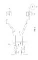
- FIG. 3is a schematic diagram of co-located RF devices configured to avoid signal interference in accordance with one embodiment of the invention.
- RF device 126 and RF device 128are co-located in apparatus 130 .
- RF devices 126 and 128are in communication with a central processing unit (not shown) through buses 134 and 136 , respectively.
- RF device 126enables a wireless local area network (WLAN) connection through the 802.11b standard and RF device 128 is a Bluetooth enabled device in one embodiment of the invention.
- WLANwireless local area network
- RF device 128is a Bluetooth enabled device in one embodiment of the invention.
- RF device 126is configured to provide wireless Ethernet transmission to access node 136 of local area network (LAN) 138 .
- LANlocal area network
- RF device 126is in communication with antenna 144 , while access node 136 is in communication with antenna 148 .
- the antennas 144 and 148transmit and receive the radio waves that RF device 126 and 148 use to communicate with each other.
- bus 132is any bus capable of interfacing with RF device 126 , such as a peripheral component micro channel interconnect architecture (PCMCIA) bus.
- PCMCIAperipheral component micro channel interconnect architecture
- RF device 128can communicate with an external Bluetooth enabled device such as RF device 140 .
- Bluetooth enabled RF device 140may be a mouse, keyboard, personal digital assistant (PDA), mobile phone, etc. which communicates with portable computer 130 .
- Bluetooth RF device 128transmits short range RF through antenna 142 to another Bluetooth device 140 , which receives the short range RF through antenna 146 .
- bus 134is any bus capable of interfacing with RF device 128 , such as a universal serial bus (USB).
- RF device 126 and RF device 128 of FIG. 3communicate with each other through communication interface 150 in one embodiment.
- Communication interface 150is a physical bus such as a Philips I 2 C bus or an Intel System Management (SM) bus. It should be appreciated that RF device 126 and RF device 128 contain appropriate bus interfaces to enable communication between device 126 and 128 .
- RF device 128can request and receive the frequency that RF device 126 operates at through communication interface 150 .
- RF device 126 and RF device 128can communicate with each other through a common central processing unit (CPU) shared by the RF devices as described below with reference to FIG. 4 .
- CPUcentral processing unit
- RF device 128can request and receive a signal indicating whether RF device 126 is in an active mode through communication interface 150 .
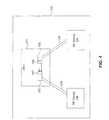
- FIG. 4is a schematic diagram of a communication interface between co-located RF devices in accordance with one embodiment of the invention.
- RF device 126 and RF device 128are co-located in apparatus 130 .
- apparatus 130is a portable computer
- RF devices 126 and 128are in communication with CPU 151 through buses 132 and 134 , respectively.
- bus 132can be any bus compatible with the IEEE 802.11b device and CPU 151 , such as a PCMCIA bus, a USB bus, etc.
- Bus 132interfaces with driver 153 .
- bus 132transports a signal to driver 153 from RF device 126 indicating the frequency at which the RF device is operating.
- a signal indicating that RF device 126 is in an active mode, i.e., transmitting or receiving,is also communicated to driver 153 .
- RF device 128is a Bluetooth enabled device
- bus 134is any bus compatible with the Bluetooth device and CPU 151 , such as a PCMCIA bus, a USB bus, etc.
- Bus 134interfaces with driver 155 .
- Driver 155which interfaces with bus 134 , includes an application programming interface (API) 159 which is configured to communicate requests to API 157 of driver 153 .
- APIapplication programming interface
- RF device 128sends a request to the API of driver 155 for the frequency the 802.11b device is operating at.
- this requestis accomplished by driver 153 communicating with driver 155 .
- a frequency range the RF device 126 is operating atis sent to driver 153 through bus 132 .
- a signal indicating that RF device 126 is in an active modei.e., transmitting or receiving, may also be transmitted to driver 153 through this pathway.
- driver 155through API 159 in communication with API 157 can access what frequency RF device 126 is operating at and when RF device 126 is active.
- RF device 126is an 802.11b device
- the frequency of operation for an 802.11b deviceis semi-stationary. That is, the 802.11b device operates within a defined range of the Industrial, Scientific and Medical (ISM) frequency band that does not change unless an access node is changed. Accordingly, RF device 128 can receive the information on the semi-stationary frequency range that RF device 126 is operating on so as to avoid the semi-stationary frequency range to eliminate interference generated from the co-located devices.
- ISMIndustrial, Scientific and Medical
- FIG. 5is a graph of frequency and time parameters to illustrate the benefits of having the knowledge of both parameters so that interference from co-located RF devices is eliminated while the bandwidth of the co-located devices is substantially maintained.
- the embodiment of an 802.11b RF chip co-located with a Bluetooth enabled chipwill be used here for illustrative purposes.
- the 802.11b standarduses direct sequence spread spectrum (DSSS).
- DSSSdirect sequence spread spectrum
- a 22 MHz frequency band within the ISM frequency rangeis used to communicate with an access node.
- This frequency bandis semi-stationary, i.e., the 802.11b uses this frequency for all communications as long as the communications are through the same access node. In other words, the semi-stationary frequency band will change if networks or access points are changed.
- the Bluetooth enabled deviceemploys a frequency hop spread spectrum (FHSS). That is, the frequency used to transmit and receive between Bluetooth devices in the ISM frequency range is constantly changing or “hopping” between 79 different channels.
- the semi-stationary frequency band that the 802.11b device is operating inis represented by width 156 of bar 152 .
- the time period that the 802.11b device is activeis represented by bar 158 .
- a co-located RF devicei.e., a Bluetooth device
- the Bluetooth devicedoes not transmit during the time that the 802.11b device is not active, since the Bluetooth device has no knowledge of the frequency of the semi-stationary band.
- the Bluetooth deviceis configured to receive the semi-stationary frequency band that the 802.11b device is operating in and the time period that the 802.11b device is active, as discussed with reference to FIG. 4 , the bandwidth of the Bluetooth device is substantially maintained.
- the intersection of bar 152 and bar 158represent the semi-stationary frequency band when the 802.11b device is active.
- the Bluetooth devicecan avoid the semi-stationary frequency when the 802.11b device is active, and while the 802.11b device is not active, the Bluetooth device is free to “hop” in the semi-stationary band without a performance penalty. In turn, the performance of the Bluetooth device is substantially maintained.
- the master-slave relationshipfits well with the properties of the 802.11b protocol and the Bluetooth standard. That is, since the 802.11b device is slower moving, i.e., semi-stationary, and does not utilize the entire ISM band at the same time it is well suited to act as the pace setter, i.e., the master.
- the fast hopping Bluetooth devicewhich uses less bandwidth is well suited for the slave.
- Bluetooth technologyalso employs a master-slave relationship which should not be confused with the master-slave concept described above.
- the device initiating the communicationacts as the master.
- Bluetooth mastersset the frequency hopping sequence while Bluetooth slaves synchronize to the master in time and frequency.
- a Bluetooth mastercan support up to seven active Bluetooth slaves.
- FIG. 6is a diagram of the timing of transmitting and receiving between the Bluetooth master and the Bluetooth slave under the Bluetooth protocol.
- the masterfirst transmits to the slave.
- both devicesare tuned to a first radio channel.
- the master and slavehop to the next channel, i.e., frequency, where at slot f 1 162 the slave responds whether it understood the last transmission from the master and is allowed to transmit any requested data to the master.
- the Bluetooth protocolutilizes a polled scheme where the Bluetooth slave is not allowed to respond to the Bluetooth master until the Bluetooth slave is polled by the Bluetooth master.
- the Bluetooth mastercontrols when the Bluetooth slave responds as well as the frequency at which the response is sent.
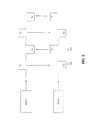
- FIG. 7is a schematic diagram of co-located Bluetooth and 802.11b RF devices in an apparatus where the Bluetooth device avoids the operating frequency of the 802.11b device and propagates the data to external Bluetooth devices in accordance with one embodiment of the invention.
- Bluetooth device 164receives the semi-stationary frequency band that 802.11b device 166 operates at and an active mode signal through communication interface 150 . As described in reference to FIG. 4 , Bluetooth device 164 may alternatively receive the frequency and active mode signal through a common CPU. Bluetooth device 164 is in communication with external Bluetooth device 168 .
- Bluetooth device 164may be incorporated in a portable computer 130 while external Bluetooth device 168 may be any number of Bluetooth enabled devices, such as a PDA, mobile phone, speakers keyboard, a second portable computer, etc.
- Bluetooth device 164initiates communication with external Bluetooth device 168 , therefore, Bluetooth device 164 is the master. It should be understood that at the same time Bluetooth device 164 is a slave to 802.11b device as described above. Thus, Bluetooth device 164 controls the frequency at which the slave responds and when the slave responds. The semi-stationary range that the 802.11b device operates at is thereby avoided in the frequency hopping of Bluetooth device 164 . As Bluetooth device 168 transmissions are controlled as to frequency and time by Bluetooth device 164 , Bluetooth device 168 also avoids the semi-stationary range that the 802.11b device operates at. It should be appreciated that while one Bluetooth slave is illustrated in FIG. 7 , up to seven slaves can be supported by a Bluetooth master. Additionally, Bluetooth device 168 can be associated with another external Bluetooth enabled RF device.
- Bluetooth device 168is the master.
- the frequency data that 802.11b device operates at and the activity mode received by Bluetooth device 164 via communication interface 150is propagated to external Bluetooth device 168 .
- the frequency hopping algorithm for Bluetooth device 168can be adjusted to avoid channels in the semi-stationary range used between 802.11b device and access node 136 . If the 802.11b device should change networks, the new semi-stationary range is propagated to external Bluetooth device 168 .
- the Link Manager protocol of the Bluetooth protocol stackis used to communicate the frequency data and the activity mode received by Bluetooth device 164 to external Bluetooth device 168 .
- a Link Manager protocol data unit (PDU) containing data indicating if certain channels can or can not be usedis sent from device 164 to external device 168 . This PDU is sent whenever the active signal changes state. In one embodiment, the PDU may be sent indicating a de-active signal.
- Propagating the channel information described aboveis optional due to the performance impacts because of the restriction of what frequencies to use.
- the propagationincreases the performance of a IEEE 802.11b link while reducing the bandwidth of the Bluetooth link when an 802.11b RF device and a Bluetooth RF device are co-located.
- Bluetooth device 164is restricted from the 22 MHz semi-stationary frequency band that the 802.11b device operates at.
- the bandwidth between Bluetooth device 164 and external Bluetooth device 168is reduced by approximately 28% (22/79) times the duty cycle of the active signal.
- both device 164 and external device 168are restricted as to what frequency to use, with device 164 only restricted when the 802.11b device 166 is active.
- device 164must propagate the state of the active signal to external device 168 .
- the bandwidth of the link between the Bluetooth devicesis reduced by approximately 57% (22/79*2) times the duty cycle of the active signal.
- external device 168is restricted all of the time irrespective of the state of the active signal.
- Device 164does not communicate the state of the active signal to external device 168 in this embodiment.
- the bandwidth between Bluetooth device 164 and external Bluetooth device 168is reduced by approximately 28% (22/79) times the duty cycle of the active signal. It should be appreciated that the reduction in bandwidth described herein is applicable when co-located Bluetooth device 164 is a slave to external Bluetooth device 168 .
- FIG. 8is a flowchart diagram of the method operations performed between first and second co-located RF devices in accordance with one embodiment of the invention.
- the first RF deviceis configured to operate within a semi-stationary range of a frequency band, such as an 802.11b device using a DSSS as described above with reference to FIGS. 3 , 5 and 7 .
- the second RF deviceis configured to operate by changing channels within the frequency band.
- the frequency bandis the ISM frequency band.
- the methodinitiates with operation 170 where a communication interface is provided between the first and second RF devices.
- the communication interfacemay be any suitable physical bus, such as a Philips I 2 C bus or an Intel SM bus, between the first and second RF device.
- the communication interfacemay be through a common CPU as described with respect to FIG. 4 .
- the methodthen advances to operation 172 where the semi-stationary range and a mode for the first RF device is received through the communication interface at the second RF device.
- the semi-stationary rangeis the frequency band that the first RF device operates at and the mode is a signal indicating whether the first RF device active, i.e., is transmitting or receiving over the semi-stationary range.
- the communication interfaceenables the second RF device to receive the semi-stationary range and the mode for the first RF device.
- the second RF devicerequests the information through the communication interface.
- the flowchart diagram of FIG. 8then moves to decision operation where it is determined if the second RF device is a slave to an external RF device. If the second RF device is not a slave to an external RF device, then the method proceeds to operation 176 where the second RF device is adapted to avoid the semi-stationary range when the first RF device is active. For example, the algorithm for determining the frequency hopping of a RF device employing FHSS is adjusted to avoid the semi-stationary range that the first RF device uses. Furthermore, the second RF device only needs to avoid the semi-stationary range when the first RF device is active. That is, when the mode indicates an active mode, the modified frequency hopping is implemented.
- the methodadvances to operation 178 where the semi-stationary range is propagated through the second RF device to the external device.
- the second RF deviceis a Bluetooth slave to a third RF device, i.e., a Bluetooth master
- the semi-stationary rangemust be propagated to the third RF device.
- the third RF deviceis adapted to avoid the semi-stationary range of the frequency band for the first RF device as described above.
- the present inventionprovides a method and an apparatus for
- the inventionmay employ various computer-implemented operations involving data stored in computer systems. These operations are those requiring physical manipulation of physical quantities. Usually, though not necessarily, these quantities take the form of electrical or magnetic signals capable of being stored, transferred, combined, compared, and otherwise manipulated. Further, the manipulations performed are often referred to in terms, such as producing, identifying, determining, or comparing.
- the inventionalso relates to a device or an apparatus for performing these operations.
- the apparatusmay be specially constructed for the required purposes, or it may be a general purpose computer selectively activated or configured by a computer program stored in the computer.
- various general purpose machinesmay be used with computer programs written in accordance with the teachings herein, or it may be more convenient to construct a more specialized apparatus to perform the required operations.
- the inventioncan also be embodied as computer readable code on a computer readable medium.
- the computer readable mediumis any data storage device that can store data which can be thereafter be read by a computer system. Examples of the computer readable medium include hard drives, network attached storage (NAS), read-only memory, random-access memory, CD-ROMs, CD-Rs, CD-RWs, magnetic tapes, and other optical and non-optical data storage devices.
- the computer readable mediumcan also be distributed over a network coupled computer systems so that the computer readable code is stored and executed in a distributed fashion.
Landscapes
- Engineering & Computer Science (AREA)
- Computer Networks & Wireless Communication (AREA)
- Signal Processing (AREA)
- Mobile Radio Communication Systems (AREA)
Abstract
Description
Claims (36)
Priority Applications (4)
| Application Number | Priority Date | Filing Date | Title |
|---|---|---|---|
| US12/758,403US8064839B2 (en) | 2001-12-28 | 2010-04-12 | Method and apparatus for co-location of two radio frequency devices |
| US13/296,143US8229364B2 (en) | 2001-12-28 | 2011-11-14 | Method and apparatus for co-location of two radio frequency devices |
| US13/552,826US8515354B2 (en) | 2001-12-28 | 2012-07-19 | Method and apparatus for co-location of two radio frequency devices |
| US13/919,879US9264152B2 (en) | 2001-12-28 | 2013-06-17 | Method and apparatus for co-location of two radio frequency devices |
Applications Claiming Priority (4)
| Application Number | Priority Date | Filing Date | Title |
|---|---|---|---|
| US34631501P | 2001-12-28 | 2001-12-28 | |
| US10/233,237US7317900B1 (en) | 2001-12-28 | 2002-08-29 | Method and apparatus for co-location of two radio frequency devices |
| US11/976,182US7720507B2 (en) | 2001-12-28 | 2007-10-22 | Method and apparatus for co-location of two radio frequency devices |
| US12/758,403US8064839B2 (en) | 2001-12-28 | 2010-04-12 | Method and apparatus for co-location of two radio frequency devices |
Related Parent Applications (1)
| Application Number | Title | Priority Date | Filing Date |
|---|---|---|---|
| US11/976,182ContinuationUS7720507B2 (en) | 2001-12-28 | 2007-10-22 | Method and apparatus for co-location of two radio frequency devices |
Related Child Applications (1)
| Application Number | Title | Priority Date | Filing Date |
|---|---|---|---|
| US13/296,143ContinuationUS8229364B2 (en) | 2001-12-28 | 2011-11-14 | Method and apparatus for co-location of two radio frequency devices |
Publications (2)
| Publication Number | Publication Date |
|---|---|
| US20100197234A1 US20100197234A1 (en) | 2010-08-05 |
| US8064839B2true US8064839B2 (en) | 2011-11-22 |
Family
ID=38893454
Family Applications (6)
| Application Number | Title | Priority Date | Filing Date |
|---|---|---|---|
| US10/233,237Expired - LifetimeUS7317900B1 (en) | 2001-12-28 | 2002-08-29 | Method and apparatus for co-location of two radio frequency devices |
| US11/976,182Expired - Fee RelatedUS7720507B2 (en) | 2001-12-28 | 2007-10-22 | Method and apparatus for co-location of two radio frequency devices |
| US12/758,403Expired - Fee RelatedUS8064839B2 (en) | 2001-12-28 | 2010-04-12 | Method and apparatus for co-location of two radio frequency devices |
| US13/296,143Expired - Fee RelatedUS8229364B2 (en) | 2001-12-28 | 2011-11-14 | Method and apparatus for co-location of two radio frequency devices |
| US13/552,826Expired - Fee RelatedUS8515354B2 (en) | 2001-12-28 | 2012-07-19 | Method and apparatus for co-location of two radio frequency devices |
| US13/919,879Expired - Fee RelatedUS9264152B2 (en) | 2001-12-28 | 2013-06-17 | Method and apparatus for co-location of two radio frequency devices |
Family Applications Before (2)
| Application Number | Title | Priority Date | Filing Date |
|---|---|---|---|
| US10/233,237Expired - LifetimeUS7317900B1 (en) | 2001-12-28 | 2002-08-29 | Method and apparatus for co-location of two radio frequency devices |
| US11/976,182Expired - Fee RelatedUS7720507B2 (en) | 2001-12-28 | 2007-10-22 | Method and apparatus for co-location of two radio frequency devices |
Family Applications After (3)
| Application Number | Title | Priority Date | Filing Date |
|---|---|---|---|
| US13/296,143Expired - Fee RelatedUS8229364B2 (en) | 2001-12-28 | 2011-11-14 | Method and apparatus for co-location of two radio frequency devices |
| US13/552,826Expired - Fee RelatedUS8515354B2 (en) | 2001-12-28 | 2012-07-19 | Method and apparatus for co-location of two radio frequency devices |
| US13/919,879Expired - Fee RelatedUS9264152B2 (en) | 2001-12-28 | 2013-06-17 | Method and apparatus for co-location of two radio frequency devices |
Country Status (1)
| Country | Link |
|---|---|
| US (6) | US7317900B1 (en) |
Cited By (2)
| Publication number | Priority date | Publication date | Assignee | Title |
|---|---|---|---|---|
| US20120058731A1 (en)* | 2001-12-28 | 2012-03-08 | Broadcom Corporation | Method and Apparatus for Co-Location of Two Radio Frequency Devices |
| US20120276859A1 (en)* | 2011-04-26 | 2012-11-01 | Renesas Mobile Corporation | Method and apparatus for avoiding in-device interference |
Families Citing this family (31)
| Publication number | Priority date | Publication date | Assignee | Title |
|---|---|---|---|---|
| US7773972B2 (en)* | 2002-05-15 | 2010-08-10 | Socket Mobile, Inc. | Functionality and policies based on wireless device dynamic associations |
| US20060132832A1 (en)* | 2004-12-17 | 2006-06-22 | Sap Aktiengesellschaft | Automated telephone number transfer |
| US7813295B2 (en)* | 2005-03-09 | 2010-10-12 | Broadcom Corporation | Co-location interference avoidance in multiple protocol communication networks |
| US8532650B2 (en)* | 2006-08-29 | 2013-09-10 | Blackberry Limited | Apparatus and method for radios occupying a common frequency region |
| US20100022237A1 (en)* | 2008-07-28 | 2010-01-28 | At&T Intellectual Property I, L.P. | Multi-mode communication system |
| US20110149164A1 (en)* | 2008-08-26 | 2011-06-23 | Netanel Goldberg | Method circuit and system for mitigating interference between wireless data and wireless video transceivers operating in proximity with one another |
| KR101478030B1 (en)* | 2009-01-29 | 2014-12-31 | 삼성전자주식회사 | Method for searching and connecting bluetooth device and apparatus using the same |
| WO2010124729A1 (en)* | 2009-04-29 | 2010-11-04 | Nokia Siemens Networks Oy | Spectrum arrangement for co-channel interference reduction |
| US9148889B2 (en)* | 2009-06-01 | 2015-09-29 | Qualcomm Incorporated | Control of multiple radios using a database of interference-related information |
| US8594056B2 (en)* | 2009-06-16 | 2013-11-26 | Qualcomm Incorporated | Method and apparatus for dynamic and dual antenna bluetooth (BT)/WLAN coexistence |
| US9161232B2 (en)* | 2009-06-29 | 2015-10-13 | Qualcomm Incorporated | Decentralized coexistence manager for controlling operation of multiple radios |
| US9185718B2 (en)* | 2009-06-29 | 2015-11-10 | Qualcomm Incorporated | Centralized coexistence manager for controlling operation of multiple radios |
| US20110007680A1 (en)* | 2009-07-09 | 2011-01-13 | Qualcomm Incorporated | Sleep mode design for coexistence manager |
| US9135197B2 (en)* | 2009-07-29 | 2015-09-15 | Qualcomm Incorporated | Asynchronous interface for multi-radio coexistence manager |
| US9185719B2 (en) | 2009-08-18 | 2015-11-10 | Qualcomm Incorporated | Method and apparatus for mapping applications to radios in a wireless communication device |
| US8942633B2 (en) | 2009-10-26 | 2015-01-27 | Mediatek Inc. | Systems and methods for activity coordination in multi-radio terminals |
| US8626067B2 (en) | 2009-10-26 | 2014-01-07 | Mediatek Inc. | System and methods for enhancing coexistence efficiency for multi-radio terminals |
| US8903314B2 (en)* | 2009-10-29 | 2014-12-02 | Qualcomm Incorporated | Bluetooth introduction sequence that replaces frequencies unusable due to other wireless technology co-resident on a bluetooth-capable device |
| KR20120017821A (en)* | 2010-08-20 | 2012-02-29 | 삼성전자주식회사 | Apparatus and method for sharing data in a portable terminal |
| US9130656B2 (en) | 2010-10-13 | 2015-09-08 | Qualcomm Incorporated | Multi-radio coexistence |
| US8892143B2 (en)* | 2011-05-10 | 2014-11-18 | Mediatek Inc. | Communication apparatus and methods for managing a communication indication assessment procedure and a wireless communications service in communications apparatus |
| KR101234942B1 (en)* | 2011-09-27 | 2013-02-19 | 삼성전기주식회사 | Method and apparatus for avoiding interference in local area wireless communication system |
| US20130114571A1 (en)* | 2011-11-07 | 2013-05-09 | Qualcomm Incorporated | Coordinated forward link blanking and power boosting for flexible bandwidth systems |
| EP2966932B1 (en)* | 2014-03-31 | 2017-07-19 | Huawei Device Co., Ltd. | Wireless fidelity wi-fi access method for user equipment and wi-fi access node |
| US9961696B2 (en)* | 2014-07-30 | 2018-05-01 | Qualcomm Incorporated | Spectrum analysis and operation of a dual radio device |
| US9510281B2 (en)* | 2014-09-19 | 2016-11-29 | Qualcomm Incorporated | Priority arbitration for interference mitigation |
| US20160149775A1 (en)* | 2014-11-23 | 2016-05-26 | Dennis Cheung | Determining physical location of a networked computing device |
| KR20160077992A (en)* | 2014-12-24 | 2016-07-04 | 삼성전자주식회사 | Method for controlling communication channel and electronic device supporting the same |
| WO2017200122A1 (en)* | 2016-05-18 | 2017-11-23 | 엘지전자 주식회사 | Position tracking device, second position tracking device, and position tracking system |
| CN109891953B (en)* | 2017-01-16 | 2020-12-08 | 华为技术有限公司 | A method for determining transmit power and wireless communication device |
| EP3382968B1 (en)* | 2017-03-31 | 2020-01-01 | Intel IP Corporation | Communication device and method for radio communication |
Citations (17)
| Publication number | Priority date | Publication date | Assignee | Title |
|---|---|---|---|---|
| US5621201A (en)* | 1994-05-11 | 1997-04-15 | Visa International | Automated purchasing control system |
| US6014561A (en) | 1996-05-06 | 2000-01-11 | Ericsson Inc. | Method and apparatus for over the air activation of a multiple mode/band radio telephone handset |
| US20010024953A1 (en) | 2000-02-24 | 2001-09-27 | Peter Balogh | Method and equipment for supporting mobility in a telecommunication system |
| US6326926B1 (en) | 2000-05-18 | 2001-12-04 | Telxon Corporation | Method of operating a wireless and a short-range wireless connection in the same frequency |
| US20020123365A1 (en)* | 2000-12-31 | 2002-09-05 | Thorson Walter R. | Scalable base station architecture |
| US6477156B1 (en) | 1999-06-29 | 2002-11-05 | Nokia Corporation | Apparatus, and associated method, for selectably operating radio device in alternate operating mode |
| US6509877B2 (en) | 2000-08-31 | 2003-01-21 | Kabushiki Kaisha Toshiba | Portable information apparatus incorporating radio communication antenna |
| US20030043040A1 (en) | 2001-08-21 | 2003-03-06 | Rob Zeps | Method and apparatus for facilitating personal attention via wireless links |
| US6560443B1 (en) | 1999-05-28 | 2003-05-06 | Nokia Corporation | Antenna sharing switching circuitry for multi-transceiver mobile terminal and method therefor |
| US6801777B2 (en) | 2001-11-27 | 2004-10-05 | Intel Corporation | Device and method for intelligent wireless communication selection |
| US6992566B2 (en)* | 2002-04-18 | 2006-01-31 | International Business Machines Corporation | Modular school computer system and method |
| US7116938B2 (en)* | 2002-08-14 | 2006-10-03 | Intel Corporation | Method and apparatus for mitigating radio frequency interference between transceiver systems |
| US7228103B2 (en)* | 2002-07-12 | 2007-06-05 | Intel Corporation | Method and apparatus for improving co-existence between bluetooth and 802.11 networks |
| US7317900B1 (en)* | 2001-12-28 | 2008-01-08 | Broadcom Corporation | Method and apparatus for co-location of two radio frequency devices |
| US7454171B2 (en)* | 2005-02-25 | 2008-11-18 | Nokia Corporation | Method and system for VoIP over WLAN to Bluetooth headset using ACL link and sniff for aligned eSCO transmission |
| US7460856B2 (en)* | 2001-12-20 | 2008-12-02 | Telefonaktiebolaget Lm Ericsson (Publ) | Method and apparatus for switching access between mobile networks |
| US7733901B2 (en)* | 1999-02-05 | 2010-06-08 | Tecore | Multi-protocol wireless communication apparatus and method |
Family Cites Families (9)
| Publication number | Priority date | Publication date | Assignee | Title |
|---|---|---|---|---|
| US5636123A (en)* | 1994-07-15 | 1997-06-03 | Rich; Richard S. | Traffic alert and collision avoidance coding system |
| US5897663A (en)* | 1996-12-24 | 1999-04-27 | Compaq Computer Corporation | Host I2 C controller for selectively executing current address reads to I2 C EEPROMs |
| US6223028B1 (en)* | 1997-03-17 | 2001-04-24 | Nortel Networks Ltd | Enhanced method and system for programming a mobile telephone over the air within a mobile telephone communication network |
| US7039358B1 (en)* | 2000-01-10 | 2006-05-02 | Symbol Technologies, Inc. | Coexistence techniques in wireless networks |
| US7440484B2 (en)* | 2000-08-09 | 2008-10-21 | Texas Instruments Incorporated | Reduced hopping sequences for a frequency hopping system |
| US6895255B1 (en)* | 2000-10-20 | 2005-05-17 | Symbol Technologies, Inc. | Dual mode wireless data communications |
| FI20002822A7 (en)* | 2000-12-21 | 2002-06-22 | Nokia Corp | Address sharing |
| US7177294B2 (en)* | 2001-03-22 | 2007-02-13 | Oxford Semiconductor, Inc. | Collision rectification in wireless communication devices |
| EP1387530A1 (en)* | 2001-05-08 | 2004-02-04 | Sony Corporation | Radio communication system, control station, communication apparatus, communication control method, radio communication method, and communication control program |
- 2002
- 2002-08-29USUS10/233,237patent/US7317900B1/ennot_activeExpired - Lifetime
- 2007
- 2007-10-22USUS11/976,182patent/US7720507B2/ennot_activeExpired - Fee Related
- 2010
- 2010-04-12USUS12/758,403patent/US8064839B2/ennot_activeExpired - Fee Related
- 2011
- 2011-11-14USUS13/296,143patent/US8229364B2/ennot_activeExpired - Fee Related
- 2012
- 2012-07-19USUS13/552,826patent/US8515354B2/ennot_activeExpired - Fee Related
- 2013
- 2013-06-17USUS13/919,879patent/US9264152B2/ennot_activeExpired - Fee Related
Patent Citations (18)
| Publication number | Priority date | Publication date | Assignee | Title |
|---|---|---|---|---|
| US5621201A (en)* | 1994-05-11 | 1997-04-15 | Visa International | Automated purchasing control system |
| US6014561A (en) | 1996-05-06 | 2000-01-11 | Ericsson Inc. | Method and apparatus for over the air activation of a multiple mode/band radio telephone handset |
| US7733901B2 (en)* | 1999-02-05 | 2010-06-08 | Tecore | Multi-protocol wireless communication apparatus and method |
| US6560443B1 (en) | 1999-05-28 | 2003-05-06 | Nokia Corporation | Antenna sharing switching circuitry for multi-transceiver mobile terminal and method therefor |
| US6477156B1 (en) | 1999-06-29 | 2002-11-05 | Nokia Corporation | Apparatus, and associated method, for selectably operating radio device in alternate operating mode |
| US20010024953A1 (en) | 2000-02-24 | 2001-09-27 | Peter Balogh | Method and equipment for supporting mobility in a telecommunication system |
| US6326926B1 (en) | 2000-05-18 | 2001-12-04 | Telxon Corporation | Method of operating a wireless and a short-range wireless connection in the same frequency |
| US6509877B2 (en) | 2000-08-31 | 2003-01-21 | Kabushiki Kaisha Toshiba | Portable information apparatus incorporating radio communication antenna |
| US20020123365A1 (en)* | 2000-12-31 | 2002-09-05 | Thorson Walter R. | Scalable base station architecture |
| US20030043040A1 (en) | 2001-08-21 | 2003-03-06 | Rob Zeps | Method and apparatus for facilitating personal attention via wireless links |
| US6801777B2 (en) | 2001-11-27 | 2004-10-05 | Intel Corporation | Device and method for intelligent wireless communication selection |
| US7460856B2 (en)* | 2001-12-20 | 2008-12-02 | Telefonaktiebolaget Lm Ericsson (Publ) | Method and apparatus for switching access between mobile networks |
| US7317900B1 (en)* | 2001-12-28 | 2008-01-08 | Broadcom Corporation | Method and apparatus for co-location of two radio frequency devices |
| US7720507B2 (en)* | 2001-12-28 | 2010-05-18 | Broadcom Corporation | Method and apparatus for co-location of two radio frequency devices |
| US6992566B2 (en)* | 2002-04-18 | 2006-01-31 | International Business Machines Corporation | Modular school computer system and method |
| US7228103B2 (en)* | 2002-07-12 | 2007-06-05 | Intel Corporation | Method and apparatus for improving co-existence between bluetooth and 802.11 networks |
| US7116938B2 (en)* | 2002-08-14 | 2006-10-03 | Intel Corporation | Method and apparatus for mitigating radio frequency interference between transceiver systems |
| US7454171B2 (en)* | 2005-02-25 | 2008-11-18 | Nokia Corporation | Method and system for VoIP over WLAN to Bluetooth headset using ACL link and sniff for aligned eSCO transmission |
Cited By (7)
| Publication number | Priority date | Publication date | Assignee | Title |
|---|---|---|---|---|
| US20120058731A1 (en)* | 2001-12-28 | 2012-03-08 | Broadcom Corporation | Method and Apparatus for Co-Location of Two Radio Frequency Devices |
| US8229364B2 (en)* | 2001-12-28 | 2012-07-24 | Broadcom Corporation | Method and apparatus for co-location of two radio frequency devices |
| US8515354B2 (en) | 2001-12-28 | 2013-08-20 | Broadcom Corporation | Method and apparatus for co-location of two radio frequency devices |
| US20130273949A1 (en)* | 2001-12-28 | 2013-10-17 | Broadcom Corporation | Method and Apparatus for Co-location of Two Radio Frequency Devices |
| US9264152B2 (en)* | 2001-12-28 | 2016-02-16 | Broadcom Corporation | Method and apparatus for co-location of two radio frequency devices |
| US20120276859A1 (en)* | 2011-04-26 | 2012-11-01 | Renesas Mobile Corporation | Method and apparatus for avoiding in-device interference |
| US8971813B2 (en)* | 2011-04-26 | 2015-03-03 | Broadcom Corporation | Method and apparatus for avoiding in-device interference |
Also Published As
| Publication number | Publication date |
|---|---|
| US20100197234A1 (en) | 2010-08-05 |
| US20120282861A1 (en) | 2012-11-08 |
| US7720507B2 (en) | 2010-05-18 |
| US20120058731A1 (en) | 2012-03-08 |
| US7317900B1 (en) | 2008-01-08 |
| US20130273949A1 (en) | 2013-10-17 |
| US9264152B2 (en) | 2016-02-16 |
| US20080056115A1 (en) | 2008-03-06 |
| US8229364B2 (en) | 2012-07-24 |
| US8515354B2 (en) | 2013-08-20 |
| US20090097388A9 (en) | 2009-04-16 |
Similar Documents
| Publication | Publication Date | Title |
|---|---|---|
| US8064839B2 (en) | Method and apparatus for co-location of two radio frequency devices | |
| EP1838040B1 (en) | Method, machine-readable storage and system for transmit power control techniques to reduce mutual interference between coexistent wireless networks | |
| TWI361607B (en) | Method and system for changing priority of slave frames in multiwire coexistence | |
| US7468963B2 (en) | Priority setting scheme for a wireless terminal | |
| US7848289B2 (en) | System and method for communicating over a wireless time-division duplex channel | |
| US7167484B2 (en) | Centralized coordination point for wireless communication devices using multiple protocols | |
| US7447505B2 (en) | System and method for coexistence in wireless networks | |
| US9295075B2 (en) | Coordinating data communications using frequency division multiplexing and time division multiplexing | |
| EP1806872B1 (en) | Method, apparatus and system for adaptively activating or deactivating the coordination of radiocommunication activities of a blutooth device and a wlan device | |
| US7286541B2 (en) | Wireless communication apparatus capable of improving connection rate | |
| EP1119112A2 (en) | Frequency hopping communication protocol | |
| JP2003512768A (en) | Method and apparatus for limiting frequency bands used in low power radio frequency devices | |
| US6970495B1 (en) | Adjustment of slave frequency hopping pattern to improve channel measurement opportunities in wireless communications | |
| JP2003508961A (en) | Resource management of unregulated frequency hopping system | |
| JP2006287424A (en) | Radio communication apparatus and method |
Legal Events
| Date | Code | Title | Description |
|---|---|---|---|
| AS | Assignment | Owner name:BROADCOM CORPORATION, CALIFORNIA Free format text:ASSIGNMENT OF ASSIGNORS INTEREST;ASSIGNOR:ZEEVO, INC.;REEL/FRAME:024304/0560 Effective date:20050801 Owner name:ZEEVO, INC., CALIFORNIA Free format text:ASSIGNMENT OF ASSIGNORS INTEREST;ASSIGNORS:LINDE, JOAKIM;FINDIKLI, AYSEGUL;JERLHAGEN, SVEN;AND OTHERS;REEL/FRAME:024219/0078 Effective date:20020828 | |
| STCF | Information on status: patent grant | Free format text:PATENTED CASE | |
| FPAY | Fee payment | Year of fee payment:4 | |
| AS | Assignment | Owner name:BANK OF AMERICA, N.A., AS COLLATERAL AGENT, NORTH CAROLINA Free format text:PATENT SECURITY AGREEMENT;ASSIGNOR:BROADCOM CORPORATION;REEL/FRAME:037806/0001 Effective date:20160201 Owner name:BANK OF AMERICA, N.A., AS COLLATERAL AGENT, NORTH Free format text:PATENT SECURITY AGREEMENT;ASSIGNOR:BROADCOM CORPORATION;REEL/FRAME:037806/0001 Effective date:20160201 | |
| AS | Assignment | Owner name:AVAGO TECHNOLOGIES GENERAL IP (SINGAPORE) PTE. LTD., SINGAPORE Free format text:ASSIGNMENT OF ASSIGNORS INTEREST;ASSIGNOR:BROADCOM CORPORATION;REEL/FRAME:041706/0001 Effective date:20170120 Owner name:AVAGO TECHNOLOGIES GENERAL IP (SINGAPORE) PTE. LTD Free format text:ASSIGNMENT OF ASSIGNORS INTEREST;ASSIGNOR:BROADCOM CORPORATION;REEL/FRAME:041706/0001 Effective date:20170120 | |
| AS | Assignment | Owner name:BROADCOM CORPORATION, CALIFORNIA Free format text:TERMINATION AND RELEASE OF SECURITY INTEREST IN PATENTS;ASSIGNOR:BANK OF AMERICA, N.A., AS COLLATERAL AGENT;REEL/FRAME:041712/0001 Effective date:20170119 | |
| AS | Assignment | Owner name:AVAGO TECHNOLOGIES INTERNATIONAL SALES PTE. LIMITE Free format text:MERGER;ASSIGNOR:AVAGO TECHNOLOGIES GENERAL IP (SINGAPORE) PTE. LTD.;REEL/FRAME:047196/0687 Effective date:20180509 | |
| AS | Assignment | Owner name:AVAGO TECHNOLOGIES INTERNATIONAL SALES PTE. LIMITE Free format text:CORRECTIVE ASSIGNMENT TO CORRECT THE EFFECTIVE DATE OF MERGER TO 9/5/2018 PREVIOUSLY RECORDED AT REEL: 047196 FRAME: 0687. ASSIGNOR(S) HEREBY CONFIRMS THE MERGER;ASSIGNOR:AVAGO TECHNOLOGIES GENERAL IP (SINGAPORE) PTE. LTD.;REEL/FRAME:047630/0344 Effective date:20180905 | |
| AS | Assignment | Owner name:AVAGO TECHNOLOGIES INTERNATIONAL SALES PTE. LIMITE Free format text:CORRECTIVE ASSIGNMENT TO CORRECT THE PROPERTY NUMBERS PREVIOUSLY RECORDED AT REEL: 47630 FRAME: 344. ASSIGNOR(S) HEREBY CONFIRMS THE ASSIGNMENT;ASSIGNOR:AVAGO TECHNOLOGIES GENERAL IP (SINGAPORE) PTE. LTD.;REEL/FRAME:048883/0267 Effective date:20180905 | |
| MAFP | Maintenance fee payment | Free format text:PAYMENT OF MAINTENANCE FEE, 8TH YEAR, LARGE ENTITY (ORIGINAL EVENT CODE: M1552); ENTITY STATUS OF PATENT OWNER: LARGE ENTITY Year of fee payment:8 | |
| FEPP | Fee payment procedure | Free format text:MAINTENANCE FEE REMINDER MAILED (ORIGINAL EVENT CODE: REM.); ENTITY STATUS OF PATENT OWNER: LARGE ENTITY | |
| LAPS | Lapse for failure to pay maintenance fees | Free format text:PATENT EXPIRED FOR FAILURE TO PAY MAINTENANCE FEES (ORIGINAL EVENT CODE: EXP.); ENTITY STATUS OF PATENT OWNER: LARGE ENTITY | |
| STCH | Information on status: patent discontinuation | Free format text:PATENT EXPIRED DUE TO NONPAYMENT OF MAINTENANCE FEES UNDER 37 CFR 1.362 | |
| FP | Lapsed due to failure to pay maintenance fee | Effective date:20231122 |