US8064835B2 - Antenna assignment system and method - Google Patents
Antenna assignment system and methodDownload PDFInfo
- Publication number
- US8064835B2 US8064835B2US11/653,135US65313507AUS8064835B2US 8064835 B2US8064835 B2US 8064835B2US 65313507 AUS65313507 AUS 65313507AUS 8064835 B2US8064835 B2US 8064835B2
- Authority
- US
- United States
- Prior art keywords
- antennas
- antenna
- subsystems
- radio
- assigning
- Prior art date
- Legal status (The legal status is an assumption and is not a legal conclusion. Google has not performed a legal analysis and makes no representation as to the accuracy of the status listed.)
- Active, expires
Links
- 238000000034methodMethods0.000titleclaimsabstractdescription39
- 230000005540biological transmissionEffects0.000claimsabstractdescription16
- 238000012549trainingMethods0.000claimsdescription13
- 238000005516engineering processMethods0.000claimsdescription4
- 230000008878couplingEffects0.000claimsdescription3
- 238000010168coupling processMethods0.000claimsdescription3
- 238000005859coupling reactionMethods0.000claimsdescription3
- 238000012913prioritisationMethods0.000claims9
- 230000003044adaptive effectEffects0.000abstract1
- 238000005457optimizationMethods0.000description7
- 230000015654memoryEffects0.000description6
- 230000006870functionEffects0.000description5
- 239000011159matrix materialSubstances0.000description5
- 238000010586diagramMethods0.000description4
- 230000008859changeEffects0.000description3
- 230000007423decreaseEffects0.000description3
- 238000005259measurementMethods0.000description3
- 230000001413cellular effectEffects0.000description2
- 238000004590computer programMethods0.000description2
- 230000003287optical effectEffects0.000description2
- 230000009471actionEffects0.000description1
- 230000010267cellular communicationEffects0.000description1
- 238000004891communicationMethods0.000description1
- 230000000694effectsEffects0.000description1
- 230000003116impacting effectEffects0.000description1
- 238000012986modificationMethods0.000description1
- 230000004048modificationEffects0.000description1
- 230000000737periodic effectEffects0.000description1
- 230000002093peripheral effectEffects0.000description1
- 230000008569processEffects0.000description1
- 238000012545processingMethods0.000description1
- 230000009467reductionEffects0.000description1
- 238000010561standard procedureMethods0.000description1
- 230000003068static effectEffects0.000description1
- 238000012360testing methodMethods0.000description1
- 238000013519translationMethods0.000description1
Images


Classifications
- H—ELECTRICITY
- H04—ELECTRIC COMMUNICATION TECHNIQUE
- H04B—TRANSMISSION
- H04B7/00—Radio transmission systems, i.e. using radiation field
- H04B7/02—Diversity systems; Multi-antenna system, i.e. transmission or reception using multiple antennas
- H04B7/04—Diversity systems; Multi-antenna system, i.e. transmission or reception using multiple antennas using two or more spaced independent antennas
- H04B7/06—Diversity systems; Multi-antenna system, i.e. transmission or reception using multiple antennas using two or more spaced independent antennas at the transmitting station
- H04B7/0686—Hybrid systems, i.e. switching and simultaneous transmission
- H04B7/0691—Hybrid systems, i.e. switching and simultaneous transmission using subgroups of transmit antennas
- H—ELECTRICITY
- H04—ELECTRIC COMMUNICATION TECHNIQUE
- H04B—TRANSMISSION
- H04B7/00—Radio transmission systems, i.e. using radiation field
- H04B7/02—Diversity systems; Multi-antenna system, i.e. transmission or reception using multiple antennas
- H04B7/04—Diversity systems; Multi-antenna system, i.e. transmission or reception using multiple antennas using two or more spaced independent antennas
- H04B7/08—Diversity systems; Multi-antenna system, i.e. transmission or reception using multiple antennas using two or more spaced independent antennas at the receiving station
- H04B7/0868—Hybrid systems, i.e. switching and combining
- H04B7/0874—Hybrid systems, i.e. switching and combining using subgroups of receive antennas
Definitions
- the inventionrelates to wireless transceivers, and more specifically to wireless transceivers with multiple radio subsystems and multiple antennas.
- Many wireless devicessupport multiple wireless systems and/or standards. For example, many cellular handsets support cellular communication via one or more of the cellular phone standards and also support Bluetooth radio communication. Similarly, many wireless LAN radio cards support the 802.11b, 802.11g, and/or 802.11n standard in the 2.4 GHz radio band as well as the 802.11a and/or 802.11n standard in the 5 GHz band. Radio signals transmitted and received through such multimode devices are transmitted and received through one or more antennas on the device.
- the allocation of antennas to a particular radio subsystemis static. It would be advantageous to be able to allocate antennas dynamically.
- a methodmay include repeating until the number of spatial streams is greater than a maximum number of spatial streams: optimizing use of antennas to support the number of spatial streams, optimizing transmission parameters, determining throughput for the number of spatial streams and the optimized transmission parameters, storing the number of spatial streams and optimized transmission parameters as optimal—and throughput as maximum throughput—if throughput is higher than a prior maximum throughput, and incrementing the number of spatial streams.
- the methodmay further include initializing a number of spatial streams to a starting value.
- a methodmay include assigning a minimum number of antennas to each of a plurality of operational radio subsystems; assigning additional antennas to meet minimum performance criteria for first one or more operational radio subsystems of the plurality of operational radio subsystems; and assigning remaining antennas, if any, to second one or more operational radio subsystems of the plurality of operational radio subsystems.
- An example of a wireless device constructed according to techniques described hereinmay include a plurality of antennas; a plurality of radio subsystems; and an antenna multiplexer dynamically coupling subsets of the plurality of antennas to one or more of the radio subsystems in accordance with a switching algorithm embodied in a computer-readable medium.
- the radio subsystemsmay operate using any known or convenient wireless standard, including by way of example but not limitation, Bluetooth, UWB, 802.11a, 802.11b, 802.11g, 802.11n, GSM, EDGE, Wideband CDMA, CDMA2000, WIMAX, or some other wireless technology.
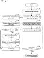
- FIG. 1depicts a flowchart of an example of a method for optimization of antenna use and transmission parameters in a radio with multiple antennas for each channel condition measurement.
- FIG. 2depicts an example of an antenna multiplexing system.
- FIG. 3depicts an example of switches in an antenna multiplexer.
- FIG. 4shows a switching algorithm on an antenna multiplexer.
- FIG. 5depicts a conceptual diagram of antenna training for a radio subsystem.
- FIG. 6depicts a flowchart of an example of a method for assignment of radio subsystems.
- FIG. 7depicts a flowchart of an example of a method for priority-sensitive antenna assignment.
- multiple antennas in a given wireless deviceconsisting of one or more radio subsystems can be used by the subsystem(s) to increase data rates through spatial multiplexing, increase link robustness through antenna diversity, steer the antenna beam in a given direction to increase directional gain and/or reduce interference, and for a combination of these benefits.
- a wireless device with one or more radio subsystems and multiple antennascan use the antennas adaptively in the manner that best meets the system's performance objectives given the application performance requirements of the different radio subsystems, channel conditions, interference conditions, and the ability to adapt the assignment of antennas to subsystems as well as various transmission parameters of each subsystem such as transmit power, constellation size, modulation type, channel coding scheme and/or rate, and frame length.
- Performance requirements for the subsystemsmay include specifications related to raw data rate, throughput, bit and/or packet error probability, average delay, and/or delay jitter as well as specifications related to system power consumption.
- specifications related to raw data rate, throughput, bit and/or packet error probability, average delay, and/or delay jitteras well as specifications related to system power consumption.
- only a subset of the total number of antennas available to one or more of the radio subsystemsmay be used to conserve system power.
- an optimization criterion for a radio system with multiple antennasis to maximize its total throughput T.
- This total system throughputis a function of how many spatial streams are transmitted (N s ), the raw physical layer data rate R i on each stream, and the probability of packet (or bit) error P i on each stream (this assumes for simplicity that the CRC checksum with an overhead of C symbols per packet consumes negligible rate.
- the overhead of the CRCis taken into account in the throughput equation below by including a multiplicative factor (L-C)/L, where L is the packet length in symbols).
- L-Cmultiplicative factor
- SINRis a function of the matrix of channel gains between all transmit and receive antennas and the interference power (in the absence of interference it is proportional to the square of the i th singular value of the channel gain matrix), and this SINR generally decreases as the number of spatial streams N s increases, since fewer spatial streams imply that fewer antennas are required for spatial multiplexing, and thus more antennas are available for diversity combining and/or interference cancellation/reduction, which increases SINR.
- FIG. 1depicts a flowchart 100 of an example of a method for optimization of antenna use and transmission parameters in a radio with multiple antennas for each channel condition measurement.
- This method and other methodsare depicted as serially arranged modules. However, modules of the methods may be reordered, or arranged for parallel execution as appropriate.
- similar optimizationcan be applied to other performance objectives that include requirements for some combination of raw data rate, throughput, bit/packet error probability, average delay, delay jitter, or any other system performance parameters such as power consumption or application requirements (e.g. target video distortion).
- Most wireless systemsuse data retransmission for packets received in error: For such systems the retransmissions may be a significant source of delay, but this delay and the associated performance requirements or constraints can be included in the optimization algorithm if delay is part of the performance objective.
- the flowchart 100begins at module 102 where channel conditions are measured. This may involve, by way of example but not limitation, determining a channel gain matrix, measuring interference, or measuring some other channel condition.
- the flowchart 100continues to module 104 where the maximum number N max of spatial streams that the multiple antennas can support given the channel measurements is computed. This may involve, by way of example but not limitation, computing the rank of the channel gain matrix.
- the flowchart 100continues to module 110 where the use of the antennas is optimized to support N s streams with roughly equal SINR per stream.
- This equalization of SINRs per streamis not limiting, and different data priorities may entail assigning higher SINRs to higher priority data streams and lower SINRs to lower priority data streams.
- Optimizing transmission parametersmay have the effect of maximizing throughput, T.
- Tmay be maximized by optimizing parameters M i and C i for each of the N s streams, given their SINR.
- the flowchart 100continues to decision point 114 where it is determined whether throughput T is higher than a prior maximum. If it is determined that T is higher than a prior maximum ( 114 -Yes), then the flowchart 100 continues to module 115 where T is set as the new maximum throughput, to module 116 where N s and the optimized transmission parameters are stored as optimal, and to module 118 where N s is incremented. If, on the other hand, it is determined that T is not higher than a prior maximum ( 114 -No), then the flowchart 100 continues to module 118 where N s is incremented.
- the flowchart 100continues to decision point 120 where it is determined whether N s >N max . If it is determined that N s >N max ( 120 -Yes), then all possible numbers of spatial streams have been optimized for and thus the optimization is complete. If, on the other hand, it is determined that N s ⁇ N max ( 120 -No), then the flowchart 100 returns to module 110 as described previously.
- antennascan be adaptively assigned to (one or more) different radio subsystems via an antenna multiplexer, and each radio system can then use its assigned antennas in the best possible manner based on an optimization algorithm (as illustrated in FIG. 1 by way of example but not limitation) to optimize its performance.
- FIG. 2depicts an example of an antenna multiplexing system 200 .
- the system 200includes a multiple antenna device 202 with antennas 204 - 1 to 204 -M (referred to collectively as antennas 204 ).
- the multiple antenna device 202includes an antenna multiplexer 206 coupled to the antennas 204 and to radio subsystems 208 - 1 to 208 -N (referred to collectively as radio subsystems 208 ).
- the antenna multiplexer 206uses a bank of switches to connect different antennas to different radio systems, as shown by way of example but not limitation in FIG. 3 .
- FIG. 3depicts an example of switches in an antenna multiplexer system 300 .
- the system 300includes antennas 304 - 1 to 304 -M (referred to collectively as antennas 304 ), an antenna multiplexer 306 , and radio subsystems 308 - 1 to 308 -N (referred to collectively as radio subsystems 308 ).
- Each of the antennas 304is coupled to switches 310 - 1 to 310 -N (referred to collectively as switches 310 ).
- Each of the switches 310is coupled to a respective one of the radio subsystems 308 .
- the antennas 304need only be designed for that band. However, in some embodiments the radio subsystems 308 may operate in different frequency bands. In this case there may be different subsets of antennas 304 that are designated for the different frequency bands, and these subsets are only assigned to the radio subsystems 308 in the appropriate bands. Alternatively, the antennas 304 can be designed to be wideband or multiband so that they can be assigned to any of the radio subsystems 308 . A third alternative would be that different subsets of the antennas 304 could support different subsets of radio subsystems 308 . For example if the radio subsystems 308 could be divided into subsets with frequencies of operation relatively close, then wideband antennas could be designed to cover each of the radio subsystem subsets.
- the radio subsystems 308could include by way of example but not limitation an IEEE 802.11g or IEEE 802.11n compatible radio (in the 2.4 GHz band), an IEEE 802.11a or IEEE 802.11n compatible radio (in the 5 GHz band), and a Bluetooth radio (in the 2.4 GHz band). If the antennas 304 are wideband or multiband across the 2.4 GHz and 5 GHz bands then any antenna could be assigned to any of the radio subsystems 308 . However, if some subset of antennas 304 covers the 2.4 GHz band only then these antennas can be assigned to either the 802.11g/n or Bluetooth subsystem, whereas all the antennas in the 5 GHz band would be assigned to the 802.11a/n subsystem.
- an IEEE 802.11g or IEEE 802.11n compatible radioin the 2.4 GHz band
- an IEEE 802.11a or IEEE 802.11n compatible radioin the 5 GHz band
- a Bluetooth radioin the 2.4 GHz band
- the switching algorithm 412uses standard techniques to control the switches 410 ; for example, the switches 410 could be designed so that if the switching algorithm 412 causes switch input to be a high voltage, a switch is open, and if the switching algorithm 412 causes switch input to be a low voltage, the switch is closed.
- other known or convenient techniquesmay be used to control the switches 410 .
- the switch algorithm 412may or may not use information from some or all of the radio subsystems 408 to determine switch control.
- This inputmay include but is not limited to subsystem priorities, subsystem requirements such as data rate, throughput, and required link SINR; subsystem conditions such as average packet delay and delay jitter, channel conditions (channel gain and interference characteristics) at each antenna, and system power constraints.
- the channel gains and interference conditionscan be obtained, for example, by a periodic full antenna training of each radio subsystem whereby all antennas that support the frequency band of that subsystem are connected to it.
- FIG. 5depicts a conceptual diagram 500 of antenna training for a radio subsystem.
- the diagram 500includes antennas 504 - 1 to 504 -M (referred to collectively as antennas 504 ), an antenna multiplexer 506 , and radio subsystems 508 - 1 to 508 -N (referred to collectively as radio subsystems 508 ).
- the antenna multiplexer 506includes a switching algorithm for training a subsystem 514 , which, in an illustrative embodiment, is embodied in a computer-readable medium.
- the diagram 500is ready to train the radio subsystem 508 - 1 , in that the antennas 504 are each connected to the radio subsystem 508 - 1 , while the antennas 504 are not coupled to the other radio subsystems 508 .
- switchesmay be used to connect (or not) the antennas 504 to the radio subsystems 508 .
- the complex channel gain, link SINR and interference power associated with each antennacan be measured, and the interference and/or signal direction (e.g., across all its frequencies) can also be measured by using beamforming (antenna weighting) across two or more antennas to point the beam associated with the antennas 508 in a given direction, and then measuring the power associated with signals (e.g., desired or interference signals) coming from that direction.
- the trainingis done for each of the radio subsystems 508 and repeated periodically, where the period of the training can be based on several factors including how often the channel conditions change as well as how often radio subsystem requirements might change.
- the radio subsystems 508may performance partial antenna training, i.e. measure channel conditions on only the antennas assigned to them, more often than full antenna training is performed. This allows each subsystem to adaptively optimize the use of its assigned antennas and the associated transmission parameters, as described by way of example but not limitation with reference to FIG. 1 , without impacting other subsystems by requiring all antennas for training.
- the method by which the switching algorithm 514 connects antennas to radio subsystemscan depend on many different factors, including which of the radio subsystems 508 are in operation (typically none of the antennas 504 will be assigned to a subsystem not in use, although some antennas and their corresponding RF paths may be shut down to save power), channel conditions associated with an antenna, the performance requirements of each subsystem and the applications it is currently running, the priorities associated with different subsystems, and the desired power consumption.
- the switching algorithm 514may not use some subset of the antennas 504 with any radio subsystem in order to conserve power.
- subsystems running voice applicationsmay receive priority over subsystems running data applications.
- FIG. 6depicts a flowchart 600 of an example of a method for assignment of radio subsystems.
- the flowchart 600starts at module 602 with assigning no antennas to non-operational subsystems. Next the algorithm will assign some minimum number of antennas to each subsystem in operation.
- antennas after the minimum performance threshold is met for all subsystemsthen these can remain unused to save power, all be assigned to the highest priority system, divided equally among all systems, or assigned unequally depending on the subsystem priorities and requirements. In particular, some subsystems with the same priority and the same minimal requirements may need more antenna resources to support a particularly demanding application being run at a given time.
- FIG. 7depicts a flowchart 700 of an example of a method for priority-sensitive antenna assignment.
- the antennas assigned to a subsystemare used for a combination of spatial multiplexing, diversity, and beamforming such that some number of independent spatial streams are obtained through spatial multiplexing to meet the desired data rate requirements, the link SINR for each of these spatial streams is met through diversity combining of antennas assigned to each spatial stream, any directionality requirements to beamform in the direction of the desired signal or away from an interference signal are met, and/or power consumption is minimized. If there are not sufficient antennas to meet the desired performance requirements of the subsystem then the available antennas are used in the best manner possible to optimize performance of the subsystem.
- the flowchart 700continues to decision point 706 where it is determined whether minimum performance requirements (MPR) are met for a high priority subsystem. If it is determined that MPR is not met for at least one high priority subsystem ( 706 -No), then the flowchart continues to module 708 where an additional antenna is assigned to the high priority subsystem.
- MPRminimum performance requirements
- module 708an additional antenna is assigned to the high priority subsystem.
- the flowchart 700loops between decision point 704 , decision point 706 , and module 708 until either all antennas have been assigned or until MPR is met for all of the high priority subsystems.
- the loops of the flowchart 700need not correspond to actual steps taken in an implementation. For example, if it is determined that MPR is not met for a high priority subsystem, all of the antennas necessary (assuming the number needed is less than or equal to R) are assigned to the high priority subsystem at once.
- each of the high priority subsystems(assuming the number needed is less than or equal to R) are assigned a single antenna with each iteration of the loop 704 , 706 , 708 .
- all of the antenna necessary(assuming the number needed is less than or equal to R) are assigned to the high priority subsystems at once.
- the use of the assigned antennas to a subsystem along with the corresponding transmission parametersare optimized for given performance criteria. If there are not sufficient antennas to meet the desired performance requirements then the algorithm uses all available antennas in the best manner possible to optimize subsystem performance.
- the flowchart 700continues to decision point 710 where it is determined whether low priority MPR are met for at least one low priority subsystem. If it is determined that low priority MPR are not met for at least one low priority subsystem ( 710 -No), then the flowchart 700 continues to module 712 where an additional antenna is assigned to the low priority subsystem, and to decision point 704 , as described previously. The loop 704 , 710 , 712 continues until all antennas have been assigned or MPR is met for all low priority subsystems. As previously noted, the flowchart 700 assumes two levels or priority, but the technique could be extended to an arbitrary number of priority levels.
- the flowchart 700continues to decision point 714 where it is determined whether power usage for the assigned antennas is below a target.
- the targetmay be set prior to the test, or calculated based upon power supply or other considerations on the fly.
- a selected subsystemmay be, for example, a high priority subsystem.
- a selection algorithmcould be used that takes into account considerations in addition to or other than priority.
- Systems described hereinmay be implemented on any of many possible computer systems having the same or different architectures.
- personal computers based on an Intel microprocessoroften have multiple buses, one of which can be an I/O bus for peripherals and one that directly connects processor and memory (often referred to as a memory bus).
- the busesare connected together through bridge components that perform any necessary translation due to differing bus protocols.
- Network computersare another type of computer system that can be used. Network computers do not usually include a hard disk or other mass storage, and the executable programs are loaded from a network connection into memory.
- a Web TV systemwhich is known in the art, is also considered to be a computer system, but it may lack some of the features typical with personal computers, such as certain input or output devices.
- An apparatus for performing techniques described hereinmay be specially constructed for the required purposes, or it may comprise a general purpose computer selectively activated or reconfigured by a computer program stored in the computer.
- a computer programmay be stored in a computer readable storage medium, such as, by way of example but not limitation, read-only memories (ROMs), RAMs, EPROMs, EEPROMs, magnetic or optical cards, any type of disk including floppy disks, optical disks, CD-ROMs, DVDs, and magnetic-optical disks, or any known or convenient type of media suitable for storing electronic instructions.
- the algorithms and displays presented hereinare not inherently related to any particular computer architecture.
- the techniquesmay be implemented using any known or convenient programming language, whether high level (e.g., C/C++) or low level (e.g., assembly language), and whether interpreted (e.g., Perl), compiled (e.g., C/C++), or Just-In-Time (JIT) compiled from bytecode (e.g., Java).
- Any known or convenient computerregardless of architecture, should be capable of executing machine code compiled or otherwise assembled from any language into machine code that is compatible with the computer's architecture, including that of embedded systems, if applicable.
Landscapes
- Engineering & Computer Science (AREA)
- Computer Networks & Wireless Communication (AREA)
- Signal Processing (AREA)
- Mobile Radio Communication Systems (AREA)
Abstract
Description
Claims (28)
Priority Applications (1)
| Application Number | Priority Date | Filing Date | Title |
|---|---|---|---|
| US11/653,135US8064835B2 (en) | 2006-01-11 | 2007-01-11 | Antenna assignment system and method |
Applications Claiming Priority (2)
| Application Number | Priority Date | Filing Date | Title |
|---|---|---|---|
| US75846606P | 2006-01-11 | 2006-01-11 | |
| US11/653,135US8064835B2 (en) | 2006-01-11 | 2007-01-11 | Antenna assignment system and method |
Publications (2)
| Publication Number | Publication Date |
|---|---|
| US20070178839A1 US20070178839A1 (en) | 2007-08-02 |
| US8064835B2true US8064835B2 (en) | 2011-11-22 |
Family
ID=38322715
Family Applications (1)
| Application Number | Title | Priority Date | Filing Date |
|---|---|---|---|
| US11/653,135Active2028-12-18US8064835B2 (en) | 2006-01-11 | 2007-01-11 | Antenna assignment system and method |
Country Status (1)
| Country | Link |
|---|---|
| US (1) | US8064835B2 (en) |
Cited By (8)
| Publication number | Priority date | Publication date | Assignee | Title |
|---|---|---|---|---|
| US20090141691A1 (en)* | 2007-11-30 | 2009-06-04 | Raj Kumar Jain | Access Point for Wireless Local Area Network |
| US20110249576A1 (en)* | 2009-12-21 | 2011-10-13 | Qualcomm Incorporated | Antenna selection based on performance metrics in a wireless device |
| US8345797B1 (en)* | 2008-12-04 | 2013-01-01 | Marvell International Ltd. | Method and apparatus for generating steering matrices for beamforming |
| CN104321980A (en)* | 2012-05-21 | 2015-01-28 | 高通股份有限公司 | Systems, apparatus, and methods for arbitration of antenna switch configuration among different clients |
| US9236929B2 (en) | 2009-12-08 | 2016-01-12 | Qualcomm Incorporated | Combined intelligent receive diversity (IRD) and mobile transmit diversity (MTD) with independent antenna switching for uplink and downlink |
| US10469140B1 (en) | 2017-10-09 | 2019-11-05 | Quantenna Communications, Inc. | WAP uplink optimization by selection of MIMO antennas spatial states |
| US10715232B2 (en) | 2016-09-13 | 2020-07-14 | Huawei Technologies Co., Ltd. | Antenna configuration method, terminal device, and antenna circuit |
| US11362776B2 (en) | 2018-11-04 | 2022-06-14 | Semiconductor Components Industries, Llc | Early link detection based adaptive selection of receive parameters |
Families Citing this family (32)
| Publication number | Priority date | Publication date | Assignee | Title |
|---|---|---|---|---|
| US7483675B2 (en)* | 2004-10-06 | 2009-01-27 | Broadcom Corporation | Method and system for weight determination in a spatial multiplexing MIMO system for WCDMA/HSDPA |
| TWI328311B (en)* | 2006-10-17 | 2010-08-01 | Accton Technology Corp | Antenna structure and communication system |
| KR20080106759A (en)* | 2007-06-04 | 2008-12-09 | 삼성전자주식회사 | Image signal processing device, display device and image signal processing method |
| US8179843B2 (en)* | 2007-07-27 | 2012-05-15 | Wisconsin Alumni Research Foundation | Distributed scheduling method for multi-antenna wireless system |
| US9037134B2 (en) | 2008-06-13 | 2015-05-19 | Qualcomm Incorporated | Mobile devices with femto cell functionality |
| US8953520B2 (en)* | 2009-02-13 | 2015-02-10 | Qualcomm Incorporated | Method and apparatus for inter-sector MIMO |
| US20110250926A1 (en)* | 2009-12-21 | 2011-10-13 | Qualcomm Incorporated | Dynamic antenna selection in a wireless device |
| US20110249760A1 (en)* | 2009-12-21 | 2011-10-13 | Qualcomm Incorporated | Antenna selection based on measurements in a wireless device |
| EP2559266B1 (en) | 2010-04-12 | 2020-10-14 | R F Products, Inc. | Rf distribution system and method of using same |
| US20120140842A1 (en)* | 2010-12-06 | 2012-06-07 | Qualcomm Incorporated | Signaling to protect advanced receiver performance in wireless local area networks (lans) |
| US8478335B2 (en)* | 2011-03-23 | 2013-07-02 | United States Of America As Represented By The Secretary Of The Navy | System and method for radio communication |
| US9113354B2 (en) | 2011-09-19 | 2015-08-18 | Redline Innovations Group Inc. | Shared backhaul link for multiple wireless systems |
| US8494587B2 (en) | 2011-09-19 | 2013-07-23 | PureWave Networks, Inc | Architecture, devices and methods for supporting multiple operators in a wireless basestation |
| US8891464B2 (en) | 2011-09-19 | 2014-11-18 | Redline Innovations Group, Inc. | Architecture, devices and methods for supporting multiple channels in a wireless system |
| US8538420B2 (en) | 2011-09-19 | 2013-09-17 | PureWave Networks, Inc | Multi-band wireless cellular system and method |
| EP2575267B1 (en)* | 2011-09-30 | 2015-03-04 | Alcatel Lucent | A base station for wireless telecommunications and a method for selecting which subset of antennas to use |
| JP5879246B2 (en)* | 2011-12-19 | 2016-03-08 | アラクサラネットワークス株式会社 | Network relay device |
| US8824976B2 (en)* | 2012-04-11 | 2014-09-02 | Qualcomm Incorporated | Devices for switching an antenna |
| US9344174B2 (en)* | 2012-05-21 | 2016-05-17 | Qualcomm Incorporated | Systems, apparatus, and methods for antenna selection |
| US9712224B2 (en)* | 2013-08-30 | 2017-07-18 | Qualcomm Incorporated | Antenna switching for dual radio devices |
| KR102200711B1 (en)* | 2013-10-11 | 2021-01-12 | 삼성전자주식회사 | Method and apparatus for controlling power considering energy efficiency in the mimo communication system |
| EP3058770A4 (en)* | 2013-10-20 | 2017-06-14 | Arbinder Singh Pabla | Wireless system with configurable radio and antenna resources |
| US9578601B2 (en)* | 2013-11-12 | 2017-02-21 | Qualcomm Incorporated | Methods and apparatus for reducing modem power based on a present state of charge of battery |
| FR3015813A1 (en)* | 2013-12-20 | 2015-06-26 | Orange | METHOD OF SLEEPING A COMMUNICATION SYSTEM COMPRISING MULTIPLE TRANSMITTING ANTENNAS |
| CN106685495A (en)* | 2015-11-05 | 2017-05-17 | 索尼公司 | Wireless communication method and wireless communication device |
| US10716157B2 (en)* | 2017-02-09 | 2020-07-14 | Apple Inc. | 5G/LTE dual connectivity |
| US11191126B2 (en) | 2017-06-05 | 2021-11-30 | Everest Networks, Inc. | Antenna systems for multi-radio communications |
| US10879627B1 (en) | 2018-04-25 | 2020-12-29 | Everest Networks, Inc. | Power recycling and output decoupling selectable RF signal divider and combiner |
| US11005194B1 (en) | 2018-04-25 | 2021-05-11 | Everest Networks, Inc. | Radio services providing with multi-radio wireless network devices with multi-segment multi-port antenna system |
| US11050470B1 (en) | 2018-04-25 | 2021-06-29 | Everest Networks, Inc. | Radio using spatial streams expansion with directional antennas |
| US11089595B1 (en) | 2018-04-26 | 2021-08-10 | Everest Networks, Inc. | Interface matrix arrangement for multi-beam, multi-port antenna |
| US11082110B2 (en)* | 2018-12-03 | 2021-08-03 | Mediatek Inc. | Communication method and communication device |
Citations (56)
| Publication number | Priority date | Publication date | Assignee | Title |
|---|---|---|---|---|
| US5268695A (en) | 1992-10-06 | 1993-12-07 | Trimble Navigation Limited | Differential phase measurement through antenna multiplexing |
| US5729558A (en) | 1995-03-08 | 1998-03-17 | Lucent Technologies Inc. | Method of compensating for Doppler error in a wireless communications system, such as for GSM and IS54 |
| US6035007A (en) | 1996-03-12 | 2000-03-07 | Ericsson Inc. | Effective bypass of error control decoder in a digital radio system |
| US6081700A (en) | 1996-12-17 | 2000-06-27 | Motorola, Inc. | Radio having a self-tuning antenna and method thereof |
| US6351499B1 (en)* | 1999-12-15 | 2002-02-26 | Iospan Wireless, Inc. | Method and wireless systems using multiple antennas and adaptive control for maximizing a communication parameter |
| US6470047B1 (en) | 2001-02-20 | 2002-10-22 | Comsys Communications Signal Processing Ltd. | Apparatus for and method of reducing interference in a communications receiver |
| US6477213B1 (en) | 1998-05-28 | 2002-11-05 | Matsushita Electric Industrial Co., Ltd. | Base station apparatus and radio communication method |
| US6477208B1 (en) | 1997-10-30 | 2002-11-05 | Comtier | Composite trellis system and method |
| US20020163879A1 (en)* | 2001-01-19 | 2002-11-07 | Xiaodong Li | Multi-carrier communication with time division multiplexing and carrier-selective loading |
| US6484285B1 (en) | 2000-02-07 | 2002-11-19 | Ericsson, Inc. | Tailbiting decoder and method |
| US20030003863A1 (en)* | 2001-05-04 | 2003-01-02 | Jorn Thielecke | Link adaptation for MIMO transmission schemes |
| US20030081701A1 (en) | 2001-10-26 | 2003-05-01 | Kobby Pick | Metric correction for multi user detection, for long codes DS-CDMA |
| US20030087673A1 (en)* | 2001-05-16 | 2003-05-08 | Walton Jay R. | Method and apparatus for allocating downlink resources in a multiple-input multiple-output (MIMO) communication system |
| US20030141938A1 (en) | 2002-01-30 | 2003-07-31 | The Aerospace Corporation | Quadrature vestigial sideband digital communications method |
| US20030157954A1 (en)* | 2002-02-19 | 2003-08-21 | Irina Medvedev | Power control for partial channel-state information (CSI) multiple-input, multiple-output (MIMO) systems |
| US20030185309A1 (en)* | 2001-04-07 | 2003-10-02 | Pautler Joseph J. | Method and system in a transceiver for controlling a multiple-input, multiple-output communications channel |
| US6642904B2 (en) | 2000-10-31 | 2003-11-04 | Mitsubishi Materials Corporation | Antenna |
| US20040013209A1 (en) | 2001-05-17 | 2004-01-22 | Ephi Zehavi | GFSK receiver |
| US6807404B2 (en) | 2000-04-25 | 2004-10-19 | Siemens Ag | Antenna diversity receiver with variable switching delay time |
| US20040234012A1 (en) | 2002-06-24 | 2004-11-25 | Rooyen Pieter Van | Reduced-complexity antenna system using multiplexed receive chain processing |
| US20040240486A1 (en) | 2003-05-30 | 2004-12-02 | Narasimhan Venkatesh | Flexible multi-channel multi-thread media access controller and physical layer interface for wireless networks |
| US20050053172A1 (en) | 2003-09-10 | 2005-03-10 | Nokia Corporation | Method and apparatus providing an advanced MIMO receiver that includes a signal-plus-residual-interference (SPRI) detector |
| US20050085269A1 (en)* | 2002-04-30 | 2005-04-21 | Soodesh Buljore | Wireless communication using multi-transmit multi-receive antenna arrays |
| US20050099937A1 (en)* | 2003-11-12 | 2005-05-12 | Samsung Electronics Co., Ltd. | Apparatus and method for sub-carrier allocation in a multiple-input and multiple-output (MIMO) orthogonal frequency division multiplexing (OFDM) communication system |
| US20050113041A1 (en)* | 2003-11-26 | 2005-05-26 | Texas Instruments Incorporated | Frequency-domain subchannel transmit antenna selection and power pouring for multi-antenna transmission |
| US20050170839A1 (en)* | 2004-02-04 | 2005-08-04 | Nokia Corporation | Variable bandwidth in a communication system |
| US20050192019A1 (en)* | 2004-02-17 | 2005-09-01 | Samsung Electronics Co., Ltd. | Apparatus and method for transmitting and receiving data in multiuser MIMO system |
| US20050195784A1 (en)* | 2004-03-05 | 2005-09-08 | Ramot At Tel Aviv University Ltd. | Antenna divison multiple access |
| US20050220057A1 (en) | 1999-06-01 | 2005-10-06 | Peter Monsen | Multiple access system and method for multibeam digital radio systems |
| US20050245201A1 (en)* | 2004-04-30 | 2005-11-03 | Nokia Corporation | Front-end topology for multiband multimode communication engines |
| US6967598B2 (en) | 2004-02-20 | 2005-11-22 | Bae Systems Information And Electronic Systems Integration Inc | Reduced complexity multi-turbo multi-user detector |
| US20050265470A1 (en)* | 2002-12-05 | 2005-12-01 | Matsushita Electric Industrial Co., Ltd. | Radio communication system, radio communication method, and radio communication device |
| US20050276361A1 (en) | 2004-06-10 | 2005-12-15 | Samsung Electronics Co., Ltd. | Interference power measurement apparatus and method for space-time beam forming |
| US20060034221A1 (en)* | 2004-08-13 | 2006-02-16 | Jeyhan Karaoguz | Multi-dimensional network resource allocation |
| US20060034217A1 (en)* | 2004-08-11 | 2006-02-16 | Samsung Electronics Co., Ltd. | Method and network device for enabling MIMO station and SISO station to coexist in wireless network without data collision |
| US20060083290A1 (en) | 2004-10-19 | 2006-04-20 | Shin Cheol H | Frequency estimation method of MB-OFDM UWB system using time frequency hopping strategy |
| US7035343B2 (en) | 2002-01-31 | 2006-04-25 | Qualcomm Inc. | Closed loop transmit diversity antenna verification using trellis decoding |
| US7058422B2 (en) | 2000-09-20 | 2006-06-06 | Bae Systems Information And Electronic Systems Integration Inc. | Method for overusing frequencies to permit simultaneous transmission of signals from two or more users on the same frequency and time slot |
| US20060223487A1 (en)* | 2005-04-04 | 2006-10-05 | Freescale Semiconductor, Inc. | Multi-band mixer and quadrature signal generator for a multi-mode radio receiver |
| US20060270427A1 (en)* | 2005-05-30 | 2006-11-30 | Masaaki Shida | Wireless transceiver |
| US20060276227A1 (en)* | 2005-06-02 | 2006-12-07 | Qualcomm Incorporated | Multi-antenna station with distributed antennas |
| WO2007021159A2 (en) | 2005-08-19 | 2007-02-22 | Samsung Electronics Co., Ltd. | Cinr estimating method and device using preamble in ofdm |
| US7194237B2 (en)* | 2002-07-30 | 2007-03-20 | Ipr Licensing Inc. | System and method for multiple-input multiple-output (MIMO) radio communication |
| US7224743B2 (en) | 2003-04-24 | 2007-05-29 | Northrop Grumman Corporation | Efficient decoding of trellis coded modulation waveforms |
| US20070136446A1 (en)* | 2005-12-01 | 2007-06-14 | Behrooz Rezvani | Wireless media server system and method |
| US20070153924A1 (en) | 2006-01-03 | 2007-07-05 | Fuyun Ling | Methods and apparatus for noise estimation in a communication system |
| US20070202818A1 (en)* | 2004-09-27 | 2007-08-30 | Naoki Okamoto | Radio Transmission Device |
| US20070258534A1 (en) | 2004-09-28 | 2007-11-08 | Rohde & Schwarz Gmbh & Co. Kg | Method and Device for Synchronizing the Carrier Frequency of an Offset Quadrature Phase-Modulated Signal |
| WO2007130578A2 (en) | 2006-05-04 | 2007-11-15 | Quantenna Communications, Inc. | Multiple antenna receiver system and method |
| US7298798B1 (en) | 2001-08-24 | 2007-11-20 | Mediatek, Inc. | Method and system for decoding block codes |
| US7321636B2 (en)* | 2001-05-31 | 2008-01-22 | Magnolia Broadband Inc. | Communication device with smart antenna using a quality-indication signal |
| US20080139123A1 (en) | 2006-12-06 | 2008-06-12 | Chungyeol Paul Lee | Method and System for Single Chip WLAN and Bluetooth Radios on a Single CMOS Substrate |
| US7400872B2 (en) | 2004-06-03 | 2008-07-15 | Oki Electric Industry Co., Ltd. | Radio receiver for selecting appropriate diversity antennas by comparing correlation values and a method for the same |
| US7450657B2 (en)* | 2005-08-18 | 2008-11-11 | Beceem Communications Inc. | Antenna virtualization in communication systems |
| US7564931B2 (en) | 2005-05-10 | 2009-07-21 | Seagate Technology Llc | Robust maximum-likelihood based timing recovery |
| US7623836B1 (en) | 2003-06-19 | 2009-11-24 | Intel Corporation | Antenna selection for multicarrier communications |
- 2007
- 2007-01-11USUS11/653,135patent/US8064835B2/enactiveActive
Patent Citations (58)
| Publication number | Priority date | Publication date | Assignee | Title |
|---|---|---|---|---|
| US5268695A (en) | 1992-10-06 | 1993-12-07 | Trimble Navigation Limited | Differential phase measurement through antenna multiplexing |
| US5729558A (en) | 1995-03-08 | 1998-03-17 | Lucent Technologies Inc. | Method of compensating for Doppler error in a wireless communications system, such as for GSM and IS54 |
| US6035007A (en) | 1996-03-12 | 2000-03-07 | Ericsson Inc. | Effective bypass of error control decoder in a digital radio system |
| US6081700A (en) | 1996-12-17 | 2000-06-27 | Motorola, Inc. | Radio having a self-tuning antenna and method thereof |
| US6477208B1 (en) | 1997-10-30 | 2002-11-05 | Comtier | Composite trellis system and method |
| US6477213B1 (en) | 1998-05-28 | 2002-11-05 | Matsushita Electric Industrial Co., Ltd. | Base station apparatus and radio communication method |
| US20050220057A1 (en) | 1999-06-01 | 2005-10-06 | Peter Monsen | Multiple access system and method for multibeam digital radio systems |
| US6351499B1 (en)* | 1999-12-15 | 2002-02-26 | Iospan Wireless, Inc. | Method and wireless systems using multiple antennas and adaptive control for maximizing a communication parameter |
| US6484285B1 (en) | 2000-02-07 | 2002-11-19 | Ericsson, Inc. | Tailbiting decoder and method |
| US6807404B2 (en) | 2000-04-25 | 2004-10-19 | Siemens Ag | Antenna diversity receiver with variable switching delay time |
| US7058422B2 (en) | 2000-09-20 | 2006-06-06 | Bae Systems Information And Electronic Systems Integration Inc. | Method for overusing frequencies to permit simultaneous transmission of signals from two or more users on the same frequency and time slot |
| US6642904B2 (en) | 2000-10-31 | 2003-11-04 | Mitsubishi Materials Corporation | Antenna |
| US20020163879A1 (en)* | 2001-01-19 | 2002-11-07 | Xiaodong Li | Multi-carrier communication with time division multiplexing and carrier-selective loading |
| US6470047B1 (en) | 2001-02-20 | 2002-10-22 | Comsys Communications Signal Processing Ltd. | Apparatus for and method of reducing interference in a communications receiver |
| US20030185309A1 (en)* | 2001-04-07 | 2003-10-02 | Pautler Joseph J. | Method and system in a transceiver for controlling a multiple-input, multiple-output communications channel |
| US20030003863A1 (en)* | 2001-05-04 | 2003-01-02 | Jorn Thielecke | Link adaptation for MIMO transmission schemes |
| US20030087673A1 (en)* | 2001-05-16 | 2003-05-08 | Walton Jay R. | Method and apparatus for allocating downlink resources in a multiple-input multiple-output (MIMO) communication system |
| US20040013209A1 (en) | 2001-05-17 | 2004-01-22 | Ephi Zehavi | GFSK receiver |
| US7321636B2 (en)* | 2001-05-31 | 2008-01-22 | Magnolia Broadband Inc. | Communication device with smart antenna using a quality-indication signal |
| US7298798B1 (en) | 2001-08-24 | 2007-11-20 | Mediatek, Inc. | Method and system for decoding block codes |
| US20030081701A1 (en) | 2001-10-26 | 2003-05-01 | Kobby Pick | Metric correction for multi user detection, for long codes DS-CDMA |
| US20030141938A1 (en) | 2002-01-30 | 2003-07-31 | The Aerospace Corporation | Quadrature vestigial sideband digital communications method |
| US7035343B2 (en) | 2002-01-31 | 2006-04-25 | Qualcomm Inc. | Closed loop transmit diversity antenna verification using trellis decoding |
| US20030157954A1 (en)* | 2002-02-19 | 2003-08-21 | Irina Medvedev | Power control for partial channel-state information (CSI) multiple-input, multiple-output (MIMO) systems |
| US20050130694A1 (en)* | 2002-02-19 | 2005-06-16 | Irina Medvedev | Power control for partial channel-state information (CSI) multiple-input, multiple-output (MIMO) systems |
| US7076263B2 (en)* | 2002-02-19 | 2006-07-11 | Qualcomm, Incorporated | Power control for partial channel-state information (CSI) multiple-input, multiple-output (MIMO) systems |
| US20050085269A1 (en)* | 2002-04-30 | 2005-04-21 | Soodesh Buljore | Wireless communication using multi-transmit multi-receive antenna arrays |
| US20040234012A1 (en) | 2002-06-24 | 2004-11-25 | Rooyen Pieter Van | Reduced-complexity antenna system using multiplexed receive chain processing |
| US7194237B2 (en)* | 2002-07-30 | 2007-03-20 | Ipr Licensing Inc. | System and method for multiple-input multiple-output (MIMO) radio communication |
| US20050265470A1 (en)* | 2002-12-05 | 2005-12-01 | Matsushita Electric Industrial Co., Ltd. | Radio communication system, radio communication method, and radio communication device |
| US7224743B2 (en) | 2003-04-24 | 2007-05-29 | Northrop Grumman Corporation | Efficient decoding of trellis coded modulation waveforms |
| US20040240486A1 (en) | 2003-05-30 | 2004-12-02 | Narasimhan Venkatesh | Flexible multi-channel multi-thread media access controller and physical layer interface for wireless networks |
| US7623836B1 (en) | 2003-06-19 | 2009-11-24 | Intel Corporation | Antenna selection for multicarrier communications |
| US20050053172A1 (en) | 2003-09-10 | 2005-03-10 | Nokia Corporation | Method and apparatus providing an advanced MIMO receiver that includes a signal-plus-residual-interference (SPRI) detector |
| US20050099937A1 (en)* | 2003-11-12 | 2005-05-12 | Samsung Electronics Co., Ltd. | Apparatus and method for sub-carrier allocation in a multiple-input and multiple-output (MIMO) orthogonal frequency division multiplexing (OFDM) communication system |
| US20050113041A1 (en)* | 2003-11-26 | 2005-05-26 | Texas Instruments Incorporated | Frequency-domain subchannel transmit antenna selection and power pouring for multi-antenna transmission |
| US20050170839A1 (en)* | 2004-02-04 | 2005-08-04 | Nokia Corporation | Variable bandwidth in a communication system |
| US20050192019A1 (en)* | 2004-02-17 | 2005-09-01 | Samsung Electronics Co., Ltd. | Apparatus and method for transmitting and receiving data in multiuser MIMO system |
| US6967598B2 (en) | 2004-02-20 | 2005-11-22 | Bae Systems Information And Electronic Systems Integration Inc | Reduced complexity multi-turbo multi-user detector |
| US20050195784A1 (en)* | 2004-03-05 | 2005-09-08 | Ramot At Tel Aviv University Ltd. | Antenna divison multiple access |
| US20050245201A1 (en)* | 2004-04-30 | 2005-11-03 | Nokia Corporation | Front-end topology for multiband multimode communication engines |
| US7400872B2 (en) | 2004-06-03 | 2008-07-15 | Oki Electric Industry Co., Ltd. | Radio receiver for selecting appropriate diversity antennas by comparing correlation values and a method for the same |
| US20050276361A1 (en) | 2004-06-10 | 2005-12-15 | Samsung Electronics Co., Ltd. | Interference power measurement apparatus and method for space-time beam forming |
| US20060034217A1 (en)* | 2004-08-11 | 2006-02-16 | Samsung Electronics Co., Ltd. | Method and network device for enabling MIMO station and SISO station to coexist in wireless network without data collision |
| US20060034221A1 (en)* | 2004-08-13 | 2006-02-16 | Jeyhan Karaoguz | Multi-dimensional network resource allocation |
| US20070202818A1 (en)* | 2004-09-27 | 2007-08-30 | Naoki Okamoto | Radio Transmission Device |
| US20070258534A1 (en) | 2004-09-28 | 2007-11-08 | Rohde & Schwarz Gmbh & Co. Kg | Method and Device for Synchronizing the Carrier Frequency of an Offset Quadrature Phase-Modulated Signal |
| US20060083290A1 (en) | 2004-10-19 | 2006-04-20 | Shin Cheol H | Frequency estimation method of MB-OFDM UWB system using time frequency hopping strategy |
| US20060223487A1 (en)* | 2005-04-04 | 2006-10-05 | Freescale Semiconductor, Inc. | Multi-band mixer and quadrature signal generator for a multi-mode radio receiver |
| US7564931B2 (en) | 2005-05-10 | 2009-07-21 | Seagate Technology Llc | Robust maximum-likelihood based timing recovery |
| US20060270427A1 (en)* | 2005-05-30 | 2006-11-30 | Masaaki Shida | Wireless transceiver |
| US20060276227A1 (en)* | 2005-06-02 | 2006-12-07 | Qualcomm Incorporated | Multi-antenna station with distributed antennas |
| US7450657B2 (en)* | 2005-08-18 | 2008-11-11 | Beceem Communications Inc. | Antenna virtualization in communication systems |
| WO2007021159A2 (en) | 2005-08-19 | 2007-02-22 | Samsung Electronics Co., Ltd. | Cinr estimating method and device using preamble in ofdm |
| US20070136446A1 (en)* | 2005-12-01 | 2007-06-14 | Behrooz Rezvani | Wireless media server system and method |
| US20070153924A1 (en) | 2006-01-03 | 2007-07-05 | Fuyun Ling | Methods and apparatus for noise estimation in a communication system |
| WO2007130578A2 (en) | 2006-05-04 | 2007-11-15 | Quantenna Communications, Inc. | Multiple antenna receiver system and method |
| US20080139123A1 (en) | 2006-12-06 | 2008-06-12 | Chungyeol Paul Lee | Method and System for Single Chip WLAN and Bluetooth Radios on a Single CMOS Substrate |
Non-Patent Citations (23)
| Title |
|---|
| Co-pending U.S. Appl. No. 11/800,357, filed May 4, 2007. |
| Co-pending U.S. Appl. No. 11/800,378, filed May 4, 2007. |
| Co-pending U.S. Appl. No. 11/872,700, filed Oct. 15, 2007. |
| Co-pending U.S. Appl. No. 12/288,569, filed Oct. 20, 2008. |
| Co-pending U.S. Appl. No. 12/299,470, filed Mar. 19, 2009. |
| Giallorenzi et al., "Noncoherent Sequence Demodulation for Trellis Coded M-DPSK", Military Communications Conference, 1991, MILCOM '91. Conference Record, Military Communication in a Changing World, IEEE, vol. 3, Nov. 1991, pp. 1023-1027. |
| Hong et al., "Detection of Amplitude-Phase Modulated Signals Over Frequency Nonselective Rayleigh Fading Channels with Adaptive Symbol-Aided Channel Estimation", 1996, Vehicular Technology Conference, 1996, Mobile Technology for the Human Race, IEEE 46th, vol. 2, pp. 983-987. |
| International Search Report of PCT/US07/10845 dated Jul. 28, 2008, pp. 1-3. |
| International Search Report of PCT/US2008/011965 dated Mar. 25, 2009, pp. 1-3. |
| International Search Report, PCT/US07/10845, (Jul. 28, 2008). |
| Non-Final Office Action Mailed Aug. 5, 2010, in Co-Pending U.S. Appl. No. 11/872,700, filed Oct. 15, 2007. |
| Non-Final Office Action Mailed May 4, 2010 in Co-pending U.S. Appl. No. 11/800,357, filed May 4, 2007. |
| Notice of Allowance dated May 12, 2011 from U.S. Appl. No. 11/800,357, filed May 4, 2007. |
| Notice of Allowance mailed Mar. 17, 2011 from U.S. Appl. No. 11/800,378, filed May 4, 2007. |
| Notice of Allowance mailed May 23, 2011 from U.S. Appl. No. 11/872,700, filed Oct. 15, 2007. |
| Office Action maield Jan. 26, 2011 from U.S. Appl. No. 12/299,470, filed Mar. 19, 2009. |
| Office Action mailed Dec. 22, 2010 from U.S. Appl. No. 11/800,357, filed May 4, 2007. |
| Office Action mailed Dec. 7, 2010 from U.S. Appl. No. 11/800,378, filed May 4, 2007. |
| Office Action mailed Feb. 15, 2011 from U.S. Appl. No. 11/872,700, filed Oct. 15, 2007. |
| Ratfai et al, IEEE Custom Integrated Circuit Conference, p. 41-1:357-361 (2005). |
| Ratfai et al, IEEE Journal of Solid State Circuits, 42(6); 1291-1299 (2007). |
| Written Opinion of PCT/US07/10845 dated Jul. 28, 2008, pp. 1-7. |
| Written Opinion of PCT/US2008/011965 dated Mar. 25, 2009, pp. 1-6. |
Cited By (17)
| Publication number | Priority date | Publication date | Assignee | Title |
|---|---|---|---|---|
| US20090141691A1 (en)* | 2007-11-30 | 2009-06-04 | Raj Kumar Jain | Access Point for Wireless Local Area Network |
| US9408254B2 (en)* | 2007-11-30 | 2016-08-02 | Lantiq Beteiligungs-GmbH & Co.KG | Access point for wireless local area network |
| US20110317679A1 (en)* | 2007-11-30 | 2011-12-29 | Lantiq Beteiligungs-GmbH & Co. KG | Access Point for Wireless Local Area Network |
| US8718176B1 (en) | 2008-12-04 | 2014-05-06 | Marvell International Ltd. | Method for computing sub-stream invariant steering matrices for MIMO beamforming |
| US8953706B1 (en) | 2008-12-04 | 2015-02-10 | Marvell International Ltd. | Method for computing sub-stream invariant steering matrices for MIMO beamforming |
| US8345797B1 (en)* | 2008-12-04 | 2013-01-01 | Marvell International Ltd. | Method and apparatus for generating steering matrices for beamforming |
| US9236929B2 (en) | 2009-12-08 | 2016-01-12 | Qualcomm Incorporated | Combined intelligent receive diversity (IRD) and mobile transmit diversity (MTD) with independent antenna switching for uplink and downlink |
| US20110249576A1 (en)* | 2009-12-21 | 2011-10-13 | Qualcomm Incorporated | Antenna selection based on performance metrics in a wireless device |
| CN104321980A (en)* | 2012-05-21 | 2015-01-28 | 高通股份有限公司 | Systems, apparatus, and methods for arbitration of antenna switch configuration among different clients |
| CN104321980B (en)* | 2012-05-21 | 2018-10-02 | 高通股份有限公司 | Systems, devices and methods for arbitrating aerial exchanging configuration between different clients |
| US10715232B2 (en) | 2016-09-13 | 2020-07-14 | Huawei Technologies Co., Ltd. | Antenna configuration method, terminal device, and antenna circuit |
| US10469140B1 (en) | 2017-10-09 | 2019-11-05 | Quantenna Communications, Inc. | WAP uplink optimization by selection of MIMO antennas spatial states |
| US10797765B2 (en) | 2017-10-09 | 2020-10-06 | Quantenna Communications, Inc. | WAP uplink optimization by selection of MIMO antennas spatial states |
| US11522582B2 (en) | 2017-10-09 | 2022-12-06 | Quantenna Communications, Inc. | WAP uplink optimization by selection of MIMO antennas spatial states |
| US11876584B2 (en) | 2017-10-09 | 2024-01-16 | Maxlinear, Inc. | WAP uplink optimization by selection of MIMO antennas spatial states |
| US11362776B2 (en) | 2018-11-04 | 2022-06-14 | Semiconductor Components Industries, Llc | Early link detection based adaptive selection of receive parameters |
| US12052189B2 (en) | 2018-11-04 | 2024-07-30 | Maxlinear, Inc. | Early link detection based adaptive selection of receive parameters |
Also Published As
| Publication number | Publication date |
|---|---|
| US20070178839A1 (en) | 2007-08-02 |
Similar Documents
| Publication | Publication Date | Title |
|---|---|---|
| US8064835B2 (en) | Antenna assignment system and method | |
| US8054837B2 (en) | Multiuser scheduling for MIMO broadcast channels with finite rate feedback | |
| JP5386746B2 (en) | Method and apparatus for utilizing a base codebook structure for beamforming | |
| US8126396B2 (en) | Wireless network that utilizes concurrent interfering transmission and MIMO techniques | |
| US20150333806A1 (en) | Techniques to manage channel prediction | |
| JP5504435B2 (en) | Method for resetting polar cap of differential codebook in wireless communication | |
| US20080159203A1 (en) | Wireless communications mode switching apparatus and methods | |
| US9474083B2 (en) | Co-scheduling based on steering vector orthogonality | |
| JP2009525694A (en) | Modulation and coding level and space velocity selection for orthogonal frequency domain modulation systems | |
| EP1992190A1 (en) | A method and apparatus for opportunistic multicasting with coded scheduling in wireless networks | |
| US7286845B2 (en) | System, and associated method, for scheduling weighted transmissions from multiple antennas | |
| US7940690B2 (en) | Apparatus and method for determining transmission mode in wireless communication system | |
| US10164722B1 (en) | Dynamic signal filter in multi-antenna system | |
| KR100965493B1 (en) | Apparatus and Method for Eliminating Adjacent Cell Interference in Wireless Communication Systems | |
| US20060268814A1 (en) | Apparatus and method for scheduling resources in a multiantenna system | |
| US7349720B2 (en) | Power efficient signal acquisition with multiple receive antennas | |
| US8767866B2 (en) | Method and apparatus for weight factor matrix determination for beam forming | |
| US9521631B2 (en) | Radio network node and method therein | |
| EP2293477A1 (en) | Radio communication device and radio communication method | |
| CN115694546A (en) | Antenna control method, electronic equipment and computer storage medium | |
| Zhou et al. | Single-antenna selection for MISO cognitive radio | |
| US20160218756A1 (en) | Subcarrier power reallocation | |
| WO2009157522A1 (en) | Wireless communication device and wireless communication method | |
| Butussi et al. | Low complexity admission in downlink beamforming | |
| WO2010035809A1 (en) | Wireless communication device and wireless communication method |
Legal Events
| Date | Code | Title | Description |
|---|---|---|---|
| AS | Assignment | Owner name:QUANTENNA COMMUNICATIONS, INC., CALIFORNIA Free format text:ASSIGNMENT OF ASSIGNORS INTEREST;ASSIGNORS:REZVANI, BEHROOZ;GOLDSMITH, ANDREA;REEL/FRAME:019080/0152 Effective date:20070315 | |
| STCF | Information on status: patent grant | Free format text:PATENTED CASE | |
| FEPP | Fee payment procedure | Free format text:PAYOR NUMBER ASSIGNED (ORIGINAL EVENT CODE: ASPN); ENTITY STATUS OF PATENT OWNER: LARGE ENTITY | |
| FEPP | Fee payment procedure | Free format text:PAT HOLDER NO LONGER CLAIMS SMALL ENTITY STATUS, ENTITY STATUS SET TO UNDISCOUNTED (ORIGINAL EVENT CODE: STOL); ENTITY STATUS OF PATENT OWNER: LARGE ENTITY | |
| FPAY | Fee payment | Year of fee payment:4 | |
| AS | Assignment | Owner name:SILICON VALLEY BANK, CALIFORNIA Free format text:SECURITY AGREEMENT;ASSIGNOR:QUANTENNA COMMUNICATIONS, INC.;REEL/FRAME:038754/0371 Effective date:20160517 | |
| MAFP | Maintenance fee payment | Free format text:PAYMENT OF MAINTENANCE FEE, 8TH YEAR, LARGE ENTITY (ORIGINAL EVENT CODE: M1552); ENTITY STATUS OF PATENT OWNER: LARGE ENTITY Year of fee payment:8 | |
| AS | Assignment | Owner name:QUANTENNA COMMUNICATIONS, INC., CALIFORNIA Free format text:RELEASE BY SECURED PARTY;ASSIGNOR:SILICON VALLEY BANK;REEL/FRAME:049332/0372 Effective date:20190528 | |
| AS | Assignment | Owner name:DEUTSCHE BANK AG NEW YORK BRANCH, AS COLLATERAL AG Free format text:PATENT SECURITY AGREEMENT;ASSIGNOR:ON SEMICONDUCTOR CONNECTIVITY SOLUTIONS, INC.;REEL/FRAME:051426/0410 Effective date:20191220 Owner name:DEUTSCHE BANK AG NEW YORK BRANCH, AS COLLATERAL AGENT, NEW YORK Free format text:PATENT SECURITY AGREEMENT;ASSIGNOR:ON SEMICONDUCTOR CONNECTIVITY SOLUTIONS, INC.;REEL/FRAME:051426/0410 Effective date:20191220 | |
| AS | Assignment | Owner name:ON SEMICONDUCTOR CONNECTIVITY SOLUTIONS, INC., CALIFORNIA Free format text:MERGER AND CHANGE OF NAME;ASSIGNORS:RAPTOR OPERATIONS SUB, INC.;QUANTENNA COMMUNICATIONS, INC.;REEL/FRAME:063271/0657 Effective date:20190619 Owner name:SEMICONDUCTOR COMPONENTS INDUSTRIES, LLC, ARIZONA Free format text:ASSIGNMENT OF ASSIGNORS INTEREST;ASSIGNOR:ON SEMICONDUCTOR CONNECTIVITY SOLUTIONS, INC.;REEL/FRAME:063280/0591 Effective date:20230406 | |
| MAFP | Maintenance fee payment | Free format text:PAYMENT OF MAINTENANCE FEE, 12TH YEAR, LARGE ENTITY (ORIGINAL EVENT CODE: M1553); ENTITY STATUS OF PATENT OWNER: LARGE ENTITY Year of fee payment:12 | |
| AS | Assignment | Owner name:ON SEMICONDUCTOR CONNECTIVITY SOLUTIONS, INC., ARIZONA Free format text:RELEASE BY SECURED PARTY;ASSIGNOR:DEUTSCHE BANK AG NEW YORK BRANCH;REEL/FRAME:063516/0736 Effective date:20230501 | |
| AS | Assignment | Owner name:MAXLINEAR, INC., CALIFORNIA Free format text:ASSIGNMENT OF ASSIGNORS INTEREST;ASSIGNOR:SEMICONDUCTOR COMPONENTS INDUSTRIES, LLC;REEL/FRAME:063572/0701 Effective date:20230502 | |
| AS | Assignment | Owner name:ON SEMICONDUCTOR CONNECTIVITY SOLUTIONS, INC., AS GRANTOR, ARIZONA Free format text:RELEASE OF SECURITY INTEREST IN PATENTS, RECORDED AT REEL 051426, FRAME 0410;ASSIGNOR:DEUTSCHE BANK AG NEW YORK BRANCH, AS COLLATERAL AGENT;REEL/FRAME:064067/0340 Effective date:20230622 |