US8064467B2 - Systems and methods for network routing in a multiple backbone network architecture - Google Patents
Systems and methods for network routing in a multiple backbone network architectureDownload PDFInfo
- Publication number
- US8064467B2 US8064467B2US11/565,563US56556306AUS8064467B2US 8064467 B2US8064467 B2US 8064467B2US 56556306 AUS56556306 AUS 56556306AUS 8064467 B2US8064467 B2US 8064467B2
- Authority
- US
- United States
- Prior art keywords
- network
- backbone
- address
- next hop
- destination
- Prior art date
- Legal status (The legal status is an assumption and is not a legal conclusion. Google has not performed a legal analysis and makes no representation as to the accuracy of the status listed.)
- Active, expires
Links
- 238000000034methodMethods0.000titleclaimsabstractdescription92
- 230000008569processEffects0.000claimsdescription48
- 238000004891communicationMethods0.000claimsdescription42
- 239000011159matrix materialSubstances0.000abstractdescription19
- GQMAOPRRHWJXFB-LBPRGKRZSA-NN(2)-(5'-phosphopyridoxyl)-L-lysineChemical compoundCC1=NC=C(COP(O)(O)=O)C(CN[C@@H](CCCCN)C(O)=O)=C1OGQMAOPRRHWJXFB-LBPRGKRZSA-N0.000description15
- 238000005516engineering processMethods0.000description4
- 230000008901benefitEffects0.000description3
- ABEXEQSGABRUHS-UHFFFAOYSA-N16-methylheptadecyl 16-methylheptadecanoateChemical compoundCC(C)CCCCCCCCCCCCCCCOC(=O)CCCCCCCCCCCCCCC(C)CABEXEQSGABRUHS-UHFFFAOYSA-N0.000description2
- 241000764238IsisSpecies0.000description2
- 238000013461designMethods0.000description2
- 230000009977dual effectEffects0.000description2
- 238000005417image-selected in vivo spectroscopyMethods0.000description2
- 238000012739integrated shape imaging systemMethods0.000description2
- 238000012986modificationMethods0.000description2
- 230000004048modificationEffects0.000description2
- 230000000644propagated effectEffects0.000description2
- 230000003068static effectEffects0.000description2
- RYGMFSIKBFXOCR-UHFFFAOYSA-NCopperChemical compound[Cu]RYGMFSIKBFXOCR-UHFFFAOYSA-N0.000description1
- 238000007792additionMethods0.000description1
- 230000006399behaviorEffects0.000description1
- 229910052802copperInorganic materials0.000description1
- 239000010949copperSubstances0.000description1
- 230000008878couplingEffects0.000description1
- 238000010168coupling processMethods0.000description1
- 238000005859coupling reactionMethods0.000description1
- 238000010586diagramMethods0.000description1
- 239000004744fabricSubstances0.000description1
- 239000000835fiberSubstances0.000description1
- 230000006870functionEffects0.000description1
- 230000005012migrationEffects0.000description1
- 238000013508migrationMethods0.000description1
- 230000003287optical effectEffects0.000description1
- 230000002093peripheral effectEffects0.000description1
- 230000001902propagating effectEffects0.000description1
- 238000011084recoveryMethods0.000description1
- 230000004044responseEffects0.000description1
Images


Classifications
- H—ELECTRICITY
- H04—ELECTRIC COMMUNICATION TECHNIQUE
- H04L—TRANSMISSION OF DIGITAL INFORMATION, e.g. TELEGRAPHIC COMMUNICATION
- H04L45/00—Routing or path finding of packets in data switching networks
- H04L45/24—Multipath
- H—ELECTRICITY
- H04—ELECTRIC COMMUNICATION TECHNIQUE
- H04L—TRANSMISSION OF DIGITAL INFORMATION, e.g. TELEGRAPHIC COMMUNICATION
- H04L45/00—Routing or path finding of packets in data switching networks
- H04L45/02—Topology update or discovery
- H04L45/04—Interdomain routing, e.g. hierarchical routing
- H—ELECTRICITY
- H04—ELECTRIC COMMUNICATION TECHNIQUE
- H04L—TRANSMISSION OF DIGITAL INFORMATION, e.g. TELEGRAPHIC COMMUNICATION
- H04L45/00—Routing or path finding of packets in data switching networks
- H04L45/60—Router architectures
- H—ELECTRICITY
- H04—ELECTRIC COMMUNICATION TECHNIQUE
- H04L—TRANSMISSION OF DIGITAL INFORMATION, e.g. TELEGRAPHIC COMMUNICATION
- H04L49/00—Packet switching elements
- H04L49/15—Interconnection of switching modules
- H04L49/1515—Non-blocking multistage, e.g. Clos
- H04L49/1523—Parallel switch fabric planes
- H—ELECTRICITY
- H04—ELECTRIC COMMUNICATION TECHNIQUE
- H04L—TRANSMISSION OF DIGITAL INFORMATION, e.g. TELEGRAPHIC COMMUNICATION
- H04L49/00—Packet switching elements
- H04L49/15—Interconnection of switching modules
- H04L49/1553—Interconnection of ATM switching modules, e.g. ATM switching fabrics
- H04L49/1569—Clos switching fabrics
Definitions
- the present inventionrelates generally to network routing, and more specifically to systems and methods for network routing in a multiple backbone network architecture.
- Embodiments of a networkinclude a backbone node that includes a plurality of independent routers or switches connected in a matrix, wherein the matrix includes a plurality of stages of routers or switches, to form a node having a node switching capacity that is greater than the node switching capacity of the individual routers or switches.
- the routers or switchesmay be connected in an N ⁇ M Internet Protocol (IP) based CLOS matrix, wherein N>1 is the number of stages in the matrix and M>1 is the number of routers or switches in each stage.
- IPInternet Protocol
- Trafficmay be directed among the routers or switches using IP or Ethernet routing protocols. Traffic may be load balanced using one or more load balancing techniques selected from a group consisting of equal cost load balancing, traffic engineering, or flow-based load balancing.
- a number of linksmay be provisioned on the routers or switches in a manner that supports the traffic balancing technique performed by the node.
- a networkinclude a plurality of backbone networks supporting communications between a source communication site and a destination communication site, a source provider edge device in communication with the plurality of backbone networks and a source provider network at the source communication site, and a destination provider edge device in communication with the plurality of backbone networks and a destination provider network at the destination communication site, wherein the destination provider edge device is configured to select one of the backbone networks from the plurality of backbone networks to handle communications associated with a destination address in the destination provider network.
- the destination provider edge deviceselects the backbone network using an external least-cost routing protocol.
- the destination provider edge devicemay associate a next hop loopback address and/or a backbone identifier with the destination address, wherein the backbone identifier identifies the selected backbone network.
- the destination provider edge devicemay further communicate an advertisement through one or more of the plurality of backbone networks, wherein the advertisement includes at least the destination address and the next hop loopback address.
- the source provider edge devicecan be configured to receive the advertisement and write the destination address and the next hop loopback address to a route map, whereby packets subsequently sent from the source network to the destination address are routed to the next hop loopback address over the selected backbone network.
- the destination provider edge devicemay communicate the advertisement during an open shortest path first (OSPF) protocol process.
- the advertisementmay further include the backbone identifier.
- OSPFopen shortest path first
- the destination provider edge devicemay associate the backbone identifier and the next hop loopback address with the destination address in a route map.
- the destination provider networkmay include a first destination provider network and the destination address may include a first destination address.
- the destination provider edge devicemay further be in communication with a second destination provider network including a second destination address at a second destination communication site, wherein the destination provider edge device is further configured to use an external least-cost routing protocol to select a second one of the backbone networks from the plurality of backbone networks to handle communications associated with the second destination address.
- the destination provider edge devicemay be further configured to associate a second next hop loopback address with the second destination address.
- the source provider edge networkmay be configured to assign a lower routing cost to the second next hop loopback address than a routing cost assigned to the next hop loopback address associated with the first destination address, whereby packets addressed to the second destination address are routed through the second backbone network.
- Embodiments of a method for routing packets to a first destination network addressinclude steps of assigning a first one of a plurality of backbone networks to the first destination network address, associating a first next hop loopback address with the first destination network address, and advertising the first destination network address in combination with the first next hop loopback address through the first backbone network address, whereby packets addressed to the first destination network address are routed through the first backbone network.
- the methodmay further include associating a first community identifier representing the first backbone network with the first destination network address.
- the methodmay further include creating a route map including an association between the first destination network address and the first next hop loopback address and an association between the first destination network address and the first community identifier.
- Some embodiments of the methodmay still further include assigning as second one of the plurality of backbone networks to a second destination network address, associating a second next hop loopback address with the second destination network address, and advertising the second destination network address in combination with the second next hop loopback address through the second backbone network address, whereby packets addressed to the second destination network address are routed through the second backbone network.
- the first backbone network and the second backbone networkmay be different backbone networks.
- packets addressed to the first destination network addressmay be routed through the first backbone network to the first next hop loopback address using an Internal Gateway Protocol.
- the methodmay further include setting an internal least cost routing metric to a provider edge site identifier.
- the methodmay include setting an internal least cost routing metric associated with the second next hop loopback address in the second backbone network equal to a value less than another internal least cost metric associated with the first next hop loopback address in the second backbone network.
- the first destination network address and the second destination network addressmay be associated with different routes through one or more customer edge networks.
- an edge router or core router associated with a backbone networkmay support two internal least cost routing protocols.
- the routercan perform a first internal least cost routing process through a port on the router facing the backbone network, and another least cost routing process through another port on the router facing an edge network.
- the first backbone networkmay serve as a backup network to the second backbone network.
- An embodiment of a computer-readable mediumincludes computer-executable instructions for causing a computer to perform a process of routing packets to a destination endpoint.
- An embodiment of the processincludes for each of a plurality of Internet service provider (ISP) networks, assigning the Internet service provider network to one of a plurality of backbone networks operating in a parallel backbone network architecture, receiving a packet addressed to a destination associated with one of the ISP networks, selecting the backbone network assigned to the ISP network associated with the destination endpoint, and routing the packet through the selected backbone network.
- ISPInternet service provider
- selecting the backbone networkincludes accessing a least-cost route map to determine which backbone network provides least cost routing to the ISP network associated with the destination endpoint. Selecting the backbone network may further include determining an address of an edge node associated with the selected backbone network. Embodiments of the process may further include receiving an advertisement from a node in each of the ISP networks and determining a least-cost backbone network from the plurality of backbone networks through which to route each of the advertisements.
- embodiments of the processmay further include further setting a next hop loopback address for each of the backbone networks, such that an internal least-cost routing process in each of the backbone networks will cause packets destined for the ISP network assigned to the backbone network to be routed to the next hop loopback address.
- the processmay further include, for each of the backbone networks, embedding the associated next hop address in an advertisement routed through the backbone network.
- the processmay also involve assigning a cost metric to each next hop loopback address based on routes associated with the next hop loopback addresses. Assigning a cost to a next hop loopback address may include assigning a cost metric to the loopback address that is lower than the cost metric for all other next hop loopback addresses for routes through the backbone network associated with the next hop loopback address.
- the network architectureincludes a plurality of backbone networks, wherein each backbone network is configured to route packets therethrough from a source network to a destination network, and a provider edge device configured to select one of the backbone networks through which to route a packet, wherein the provider edge device selects a least-cost backbone network assigned to the destination network, wherein the least-cost backbone network is selected from the plurality of backbone networks.
- the provider edge devicemay be further configured to assign one of the plurality of backbone networks to the destination network based on a least-cost routing protocol.
- the provider edge devicemay be configured to receive an advertisement message from the destination network and route the advertisement message through the assigned backbone network, where by other provider edge devices route packets destined for the destination network through the assigned backbone network.
- the provider edge devicemay be further configured to embed a next hop loopback address in the advertisement message.
- the provider edge devicemay be further configured to assign a cost metric to the next hop loopback address. The cost metric may be chosen relative to other cost metrics associated with other next hop loopback addresses based on a route associated with the next hop loopback address.
- the provider edge devicemay be configured to receive an advertisement message associated with another network and assign a next hop loopback address included in the advertisement message to the backbone network from which the advertisement message was received.
- the provider edge devicemay assign the next hop loopback address to the backbone network in a route map.
- the provider edge devicemay be further configured to build a least-cost routing table that associates each of a plurality of next hop loopback addresses with a cost metric based on the backbone network associated with the next hop loopback address.
- At least one of backbone networksmay serve as a backup network to at least one of the other backbone networks.
- At least one of the backbone networksmay include a backbone node including an N ⁇ M IP-implemented CLOS matrix of Ethernet switches, where N>1 is the number of stages in the matrix and M>1 is the number or switches in each stage.
- An embodiment of a method for providing communications between provider networksincludes for each of a plurality of communication routes through one or more provider networks: receiving an advertisement having a network address associated with the communication route, selecting a backbone network from a plurality of backbone networks using an external least-cost routing protocol, associating a first next hop loopback address with the destination address, wherein the first next hop loopback address is reachable via the selected backbone network, assigning a first cost to the next hop loopback address, wherein the first cost is less than a second cost associated with a second next hop loopback address reachable by another backbone network, advertising the first next hop loopback address over the plurality of backbone networks, wherein advertising includes indicating the first cost of accessing the first next hop loopback address via the selected backbone network.
- Yet another embodiment of a methodincludes assigning a destination network address to a backbone network selected from a plurality of backbone networks using an external least cost routing protocol, associating a next hop loopback address with the destination network address, wherein the next hop loopback address corresponds to a port on a destination provider edge device in communication with the selected backbone network, notifying a source provider edge device that the next hop loopback address is reachable with least cost routing via the selected backbone network.
- Notifying the source provider edge devicemay include performing an internal least cost routing protocol between the source provider edge device and a source core router device in the selected backbone network.
- the methodmay further include performing the internal least cost routing protocol process between the source core router device and a destination core router device to determine a cost associated with the next hop loopback address.
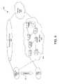
- FIG. 1is a diagrammatic illustration of a three-stage multichassis Ethernet router (MER) in accordance with one embodiment of the invention.
- MERmultichassis Ethernet router
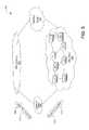
- FIG. 2is a diagrammatic illustration of multiple parallel backbones (N ⁇ BB) connected to peer and edge networks in accordance with another embodiment of the invention.
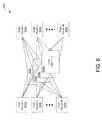
- FIG. 3is a diagrammatic illustration of a combination of the multichassis Ethernet router shown in FIG. 1 and the multiple parallel backbones shown in FIG. 2 connected between sites in accordance with another embodiment of the invention.
- FIG. 4is a diagrammatic illustration of a multichassis Ethernet router-based core network in parallel with one or more Multiple protocol Label Switching (MPLS) core networks providing packet routing between sites, wherein a subset of the customer/provider packet traffic is regroomed or migrated to a second customer/provider edge network in accordance with another embodiment of the invention.
- MPLSMultiple protocol Label Switching
- FIG. 5is a diagrammatic illustration of a MER-based backbone network in parallel with an MPLS backbone network providing packet routing between a single customer/provider edge network and a peering edge network in accordance with one embodiment of the invention.
- FIG. 6is a diagrammatic illustration of multiple core local area networks (LANs) communicably connected between one or more core routers and one or more edge routers in accordance with another embodiment of the invention.
- LANslocal area networks
- FIG. 7is a diagrammatic illustration of an alternative LAN in the middle (LIM).
- FIG. 8illustrates an exemplary network architecture including multiple parallel backbone networks, wherein customer addresses are advertised and associated with next hop loopback addresses, whereby packets destined for each of those addresses are routed through a selected backbone network.
- FIG. 9illustrates the exemplary network architecture shown in FIG. 8 , wherein advertisements are tagged with backbone identifiers to indicate destination-based backbone routes, and costs are assigned to next hop loopback addresses to enforce routing of packets through an associated backbone network.
- FIG. 10illustrates a dual internal cost-based link state generation process in which edge routers on the edges of backbone networks in a multiple parallel backbone network architecture run two internal cost-based link state generation processes for a wide area network facing side and a local area network facing side.
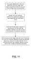
- FIG. 11is a flowchart illustrating an algorithm for carrying out routing in a multiple backbone network architecture in accordance with one embodiment.
- FIG. 12illustrates a general purpose computing device in which embodiments of the invention can be implemented.
- Embodimentsinclude systems and methods that provide for multiple backbone networks to support communications between networks.
- a first routing protocolis used by a provider edge device to select a backbone network from the multiple backbone networks for handling communications associated with one or more associated network addresses.
- the provider edge network deviceassigns a port with a next hop loopback address to the associated one or more network addresses.
- a second routing protocolis used to notify other provider edge network devices that the selected backbone network should be used to carry packets addressed to the associated one or more network addresses.
- Exemplary networks that utilize the services of backbone networksare Internet service provider (ISP) or network service providers (NSPs) networks that provide end user network services to home and business Internet users.
- ISPstypically have networks at multiple geographic sites where the backbone network also has provider edge network devices to interface with ISP networks. More specifically, embodiments provide for assigning one of a plurality of backbone networks to handle communications associated with an ISP network address.
- An external least cost routing protocol processsuch as border gateway protocol (BGP), can be used to assign a backbone network to an ISP network address.
- BGPborder gateway protocol
- An internal least cost routing protocol processcan be used to ensure that packets addressed to the ISP network address are routed through the assigned backbone.
- a provider edge nodecarries out an external least cost routing protocol to select a least cost backbone associated with a given ISP network address.
- the provider edge nodeassigns a next hop loopback address to the given ISP network address.
- the next hop loopback addressis reachable through the selected backbone network.
- the next hop loopback addressis advertised in combination with the given ISP network address over one or more of the backbone networks.
- An internal least cost routing protocol processis carried out to notify one or more other provider edge devices that the next hop loopback address is reachable at least cost through the selected backbone network.
- a backbone identifieris associated with a given ISP network address, along with the associated next hop loopback address.
- One or more provider edge nodescan update or create a route map to include an association between the given ISP network address, the backbone identifier, and the next hop loopback address.
- an external least cost routing protocol processcan be carried out for multiple ISP network addresses being advertised to a backbone service provider network. Because there are multiple backbones in the backbone service provider network, one or more of the ISP network addresses may be assigned a backbone network that is different from the backbone network that is assigned to one or more other ISP network addresses. The one or more ISP network addresses could be associated with a single ISP network or multiple ISP networks. As such, different ISP network addresses in one ISP network could be assigned different backbone networks.
- next hop loopback addressis tagged with an identifier for the assigned backbone network.
- An advertisementcan include a tag associated with the assigned backbone network and/or the next hop loopback address, in order to identify a route through the assigned backbone network to handle communications for associated network addresses.
- the backbone network selection process and the existence of multiple backbone networksis invisible to the ISP networks and endpoints associated with the ISP network addresses. As such, backbone network service with multiple backbone networks need not appear any different than backbone network service with a single backbone network.
- a particular backbone networkis assigned to each ISP network address, in some embodiments, one or more other backbone networks can be used as backup networks for the assigned backbone network.
- a backbone network service providerinitially has one backbone network.
- the backbone network service providermay add one or more backbone networks to the backbone network service provider network.
- ISP network addresses and/or routesmay be migrated from the initial backbone network to one or more of the new backbone networks.
- Migratinginvolves reassigning one or more ISP network addresses to the new backbone networks.
- a redistribution processcan be performed to cause provider edge devices to route packets to a destination ISP network address via the backbone network assigned to the destination ISP network address.
- An embodiment of the redistribution processincludes core nodes on a new backbone network carrying out an internal least cost routing protocol process with provider edge nodes and another internal least cost routing protocol process with core nodes throughout the new backbone network.
- the next hop loopback address associated with the new backbone network and associated migrated ISP network addressesare advertised across the new backbone network with a lower cost metric than the a corresponding cost metric for the initial backbone network.
- Some embodimentsrelate to a network architecture that includes a backbone node having of independent routers or switches connected in matrix configuration resulting in a node switching capacity that is greater than the node switching capacity of the individual routers.
- the routers or switchesmay be connected in an N ⁇ M Internet Protocol (IP) implemented CLOS matrix, where N>1 is the number of stages in the matrix and M>1 is the number of routers or switches in each stage.
- IPInternet Protocol
- the trafficis directed among the routers or switches using standard IP or Ethernet routing protocols and load balancing techniques that may include but are not limited to equal cost load balancing, traffic engineering, or flow based load balancing.
- the linksare provisioned on the routers in a manner to best interoperate with traffic balancing of the node.
- a moduleis a self-contained functional component.
- a modulemay be implemented in hardware, software, firmware, or any combination thereof.
- connectionor “coupled” and related terms are used in an operational sense and are not necessarily limited to a direct connection or coupling.
- responsiveand “in response to” includes completely or partially responsive.
- Computer-readable mediais media that is accessible by a computer, and can include, without limitation, computer storage media and communications media.
- Computer storage mediagenerally refers to any type of computer-readable memory, such as, but not limited to, volatile, non-volatile, removable, or non-removable memory.
- Communication mediarefers to a modulated signal carrying computer-readable data, such as, without limitation, program modules, instructions, or data structures.
- backbone networkrefers to a network that communicably connects two or more networks or subnetworks and provides communication traffic routing therebetween.
- a backbone networkis typically geographically distributed to provide routing between multiple geographic sites.
- a backbone networkis a wide area network (WAN).
- Backbone networksinclude core routers and other nodes that facilitate packet routing.
- a “customer network” or “provider network”are examples of third party networks that may interface with a provider edge network or device to thereby communicate across one or more backbone networks.
- a “customer edge device” or “provider edge device”are devices that interface with third party networks, such as customer networks, and one or more backbone networks to route traffic between the third party networks and the one or more backbone networks.
- customer edge devicesinterface with one or more core nodes, such as core routers, in the backbone networks to route communication traffic to and from the backbone networks.
- a “customer edge network”, “provider edge network”, or “peering edge network”are networks communicably between third party networks and one or more backbone networks, and include one or more customer edge devices.
- a local area networkis communicably located between backbone network core nodes and customer edge network nodes.
- the systemsinclude a multi-chassis Ethernet router (“MER”), a multiple parallel backbone configuration (“N ⁇ BB”), and a LAN in the middle (“LIM”) configuration,
- MERmulti-chassis Ethernet router
- N ⁇ BBmultiple parallel backbone configuration
- LIMLAN in the middle
- Ethernet switch matricescan be used in place of the terabit Multiple protocol Label Switching (MPLS) backbone routers, as well as in place of gigabit access routers at the edge of a network backbone. By using the Ethernet switch matrices, unit costs can be lowered.
- MPLSMultiple protocol Label Switching
- the MERwill comprise a multi-stage CLOS matrix (e.g., 3 stages) router built out of Ethernet switches.
- the MERwill use IP protocols to distribute traffic load across multiple switch stages. This design leverages existing technology, but allows scalability by adding additional Ethernet switches, additional stages, a combination or both, or new, inexpensive MERs.
- FIG. 1is a diagrammatic illustration of one embodiment of a 3-stage MER 100 in accordance with one embodiment of the invention.
- the MERutilizes 4 Ethernet switches 102 in each of the three stages 104 a - 104 c . Again, additional switches 102 or stages can be added.
- traffic destined out L 34arrives at L 11 .
- L 11equally distributes the traffic across L 21 -L 24 using one or more load balancing or distribution methods.
- L 21 -L 24forwards traffic to L 34 , which combines the flows and forwards them out the necessary links. This design provides a dramatic increase in scale.
- a 4 ⁇ MER 100provides a 4 ⁇ increase in node size.
- the maximum increase for a 3 stage fabricis (n ⁇ 2)/2, where n is the number of switches used in each stage. Five stage and seven stage matrices will further increase scalability.
- the Multi-Chassis Ethernet Router 100may be viewed as a packet-level CLOS matrix. While CLOS matrices are known for use in bit-level applications, CLOS matrices have not been implemented in a network of Ethernet switches operating on the packet level, which is what this particular implementation provides. Further, the CLOS matrices typically implemented in the very expensive MPLS routers are implemented using proprietary software and are encompassed into a single box. In this particular implementation, multiple inexpensive Ethernet switches are formed into the matrix, and the CLOS distribution is implemented using IP protocols, rather than a proprietary software. Further, in this particular implementation, the CLOS matrix is implemented at each hop of the switches, instead of in a single device. Other protocols can be used in other embodiments.
- the packets and/or packet cellscan be distributed to the different stages 104 of the matrix using flow based load balancing.
- Internal gateway protocolsIGP
- IGPInternal gateway protocols
- the MER 100can utilize equal cost load balancing, so that each third-stage box (i.e., L 31 , L 32 , L 33 and L 34 ) associated with a destination receives the same amount of traffic. For example, if boxes L 1 , L 2 and L 3 all communicate with a New York-based provider edge site or router, each box will receive the same amount of traffic. This technique is relatively easy to implement and scales well, when new MERs are implemented.
- traffic on the MER 100can be distributed using bandwidth aware load balancing techniques, such as traffic engineering techniques (e.g., MPLS traffic engineering) that send packets to the least busy switch.
- traffic engineering techniquese.g., MPLS traffic engineering
- the middle layer 104 bcan run the traffic engineering functionality, thus making intelligent routing decisions.
- traffic awareness techniques in the middle layer 104 bcan be used to determine what the downstream traffic requirements might be. That is, the middle layer 104 b can determine demand placed on the third or last layer 104 c and then determine routing based on the capacity needs. In this embodiment, the middle layer 104 b can receive demand or capacity information from the last (e.g., third) layer 104 c via traffic engineering tunnels (e.g., MPLS tunnels) or via layer 2 VLANS. Alternatively, changes to IGP can be leveraged to communicate bandwidth information to the middle layer 104 b .
- traffic engineering tunnelse.g., MPLS tunnels
- switch L 31can communicate to the middle layer 104 b (e.g., via IGP or other protocols) that it is connected to a New York-based site with 30 Gb of traffic.
- the middle layer 104 bcan use this protocol information, as well as information from the other switches, to load balance the MER 100 .
- an implementation of the MER 100can use a control box or a route reflector to manage the MER 100 .
- the route reflector or control boxcan participate in or control routing protocols, keep routing statistics, trouble shoot problems with the MER, scale routing protocols, or the like.
- the route reflectorcan implement the routing protocols. So, instead of a third stage in a MER communicating with a third stage in another MER, a route reflector associated with a MER could communicate with a route reflector associated with the other MER to determine routing needs and protocols.
- the route reflectorcould utilize border gateway protocols (“BGP”) or IGP route reflection protocols could be used (e.g., the route reflector could act as an area border router).
- Border gateway protocols(“BGP”) or IGP route reflection protocols could be used (e.g., the route reflector could act as an area border router).
- FIG. 2Another implementation that can be utilized to scale a core backbone network is to create multiple parallel backbone networks.
- a multiple parallel backbone architecture 200is illustrated in FIG. 2 .
- trafficcan be split across multiple backbones to increase scale.
- each backbone networkcan be selectively assigned to one or more network addresses, such that the assigned backbone network handles communication traffic (e.g., packets) associated with the assigned one or more network addresses.
- the multiple parallel backbone architecture 200has deployed therein a series of parallel backbone networks 202 a - 202 e between core sites.
- the backbonescan use large MPLS routers, Ethernet switches, the MERs discussed above, or any other suitable routing technology.
- peers 204 a - 204 ncan connect to the backbones 202 through a common peering infrastructure or edge 206 connected to each backbone, and customers 208 a - 208 n can connect to specific backbone edges 210 a - 210 e .
- peers 204are connected to the parallel backbone networks 202 (BB, BB 1 , BB 2 , BB 3 and BB 4 ) through a single peering edge 206 , and customers 208 are connected to the backbones 202 through separate edge networks 210 .
- each backbone network 202has its own customer edge 210 network. In alternative embodiments, however, only one or just a couple of edge networks 210 might be utilized (similar to one peering edge).
- the edge network 210also can use different routing technologies, including the MERs discussed above. The use of MERs can help with scaling of the peering edge 206 .
- the arrows in FIG. 2illustrate an example of traffic flows 212 in a parallel backbone network architecture 200 .
- traffic 214 destined for customers A-Z 208 a - 208 narrives from Peer #2 204 b Devices on the peering edge network 206 , such as provider edge devices, split traffic across the multiple backbones 202 based on the final destination of the traffic (e.g., peering edge 206 can distribute traffic based on IP destination prefix). Then each of the backbones 202 forwards traffic through its associated customer edge 210 to the final customer 208 destination.
- This multiple parallel backbone network 200can have many advantages. For example, parallel backbone networks 202 make switching needs smaller in each backbone, so Ethernet switches and/or MERs can be used.
- the parallel backbone configuration 200can leverage existing routing and control protocols, such as BGP tools like traffic engineering, confederations, MBGP, and the like. The use of the traffic engineering protocols can help steer traffic to the appropriate backbone network(s) 202 .
- fault tolerant back-up systemscan be created for mission critical applications. That is, one or more backbone networks 202 can be used for disaster recovery and/or back-up purposes.
- the parallel backbones 202can be organized and utilized based on different factors.
- a peer 204could have one or more backbone networks 202 dedicated to it.
- a customer network 208e.g., an ISP network
- customers 208can be allocated across backbones 202 based on traffic and/or services.
- VoIPVoice Over IP
- backbones 202can be provisioned by peer 204 , customer 208 , service, traffic volume or any other suitable provisioning parameter.
- a combination of multi-chassis Ethernet routers (MER) 302 and parallel backbones (N ⁇ BB) 304can be used for even greater scaling.
- MERmulti-chassis Ethernet routers
- N ⁇ BBparallel backbones
- a 300G Ethernet switch 306 capacitycould be increased 64 ⁇ to 19,200G using a combination of MER 302 and parallel backbones 304 .
- an 8 ⁇ MER 310 and an 8 ⁇ parallel backbone architecture 312is combined to obtain a 64 ⁇ scalability multiple parallel MER-based network architecture 314 .
- Scalabilitycan be even larger if larger MERs 302 (e.g., 16 ⁇ or 32 ⁇ ) and/or more parallel backbones 304 are used.
- these technologies used alone and/or togethercan help scale capacity greatly.
- an Ethernet-based core network 402(e.g., a core network based on MERs 404 ) can be added as a parallel core network 402 to existing MPLS core networks 406 , thus adding easy scalability at a reasonable price without having to replace existing core networks 402 .
- the new parallel core network 402 and the MPLS core network 406are interconnected at peering sites in a peering edge network 408 .
- some existing customers as well as new customerscould be migrated 410 from an existing customer edge network 412 to a new customer edge network 414 . Traffic for the customers who are migrated to the new customer edge network 414 could be routed to the new Ethernet-core backbone 402 .
- specific services, such as VoIPcould be put on the new backbone 402 , while leaving other services on the MPLS network 406 .
- Many different scenarios of use of the two corescould be contemplated and used.
- FIG. 5is another illustration of the Ethernet-based parallel core 502 in parallel with an existing MPLS core 504 .
- External least cost routing protocol techniquessuch as BGP techniques, can be used to select which backbone to use on a per destination basis.
- destination addresses A. 1 and A. 2are advertised through a customer edge network 506 .
- Candidate routesare marked with a BGP community identifier, such as community string 508 or 510 (and IP next hop loopback address), as illustrated with advertisements 512 and 514 , respectively.
- the community stringsare used in the least-cost routing process to route packets destined for address “A. 1 ” through backbone 0 (BB 0 ), and to route packets destined for address “A. 2 ” through backbone 2 (BB 2 ).
- community stringscan effectively force packets through the backbone networks based on the destination address.
- the selectioncan be done on a route by route basis and could vary based on source.
- provider edge devices in the provider edge network 516select the backbone based on route.
- a customer-based global policycan be used so that all traffic exiting a specific set of customer parts would use the same backbone.
- Route selection and route mapscan be automatically generated by capacity planning tools.
- LIMAnother network implementation that could used to scale backbone cores is the LIM.
- a LIM 602is illustrated in FIG. 6 .
- core routers 604 a - 604 nare connected to edge routers 606 a - 606 n through Ethernet switches 608 a - 608 n .
- Thisis a similar configuration to the MERs discussed above, except existing core routers and edge routers are used in stages 1 and 3, instead of all stages using Ethernet switches.
- the benefit of this configurationis that the existing routers can be scaled larger without having to replace them with Ethernet switches.
- Using Ethernet switches in the middle layer and using CLOS matrices, as discussed above,will increase capacity of the existing core routers 604 and edge routers 606 .
- the core 604 and edge routers 606will be responsible for provisioning the traffic through the matrix 608 .
- FIG. 7is a diagrammatic illustration of an alternative embodiment of a LIM 700 .
- Customer facing provider edges (PE) 702can, for example, have 4 ⁇ 10G to the LIM. With a 1+1 protection, this would allow 20G customer facing working traffic.
- each provider or core router (P) 704has 4 ⁇ 10 G to the LIM. With 1+1 protection, this allows at least 20 G of WAN traffic.
- FIG. 8illustrates an exemplary network 800 including multiple parallel backbone networks 802 a - 802 b and a provider edge device 804 .
- the network 800provides backbone network services to first and second customer networks, such as customer network A 806 a and customer network B 806 b .
- Customer network A 806 ahas an associated IP address denoted here as A. 1 for ease of illustration, and customer network B 806 b has an associated IP address of B. 1 .
- IP addresses reachable on the customer network A 806 aare more generally denoted as A.X and IP addresses reachable on the customer network B 806 b are more generally denoted as B.x.
- Nodes, such as routers, on the customer network A 806 a and the customer network B 806 badvertise A.X addresses and B.X addresses, respectively, so that the provider edge device PE 1 804 , and other network 800 nodes, can determine how to route packets to the A.X addresses and B.X addresses.
- Advertisements from customer network A 806 a and customer network B 806 bare illustrated by arrows 808 a and 808 b , respectively.
- PE 1 804is labeled with site identifier “WDC”, which stands for Washington D.C.
- WDCsite identifier
- PE 1 804handles communications associated with customer networks in the Washington D.C area.
- WDCsite identifier
- the use of WDC, or any other specific site identifier,is merely for illustrative convenience, and it will be understood by those skilled in the art that the processes described here with respect to PE 1 804 can be carried out by any provider edge device, regardless of the customer site.
- the description hererelates to processes for routing packets to customer addresses when multiple backbone networks are employed. Therefore, although nodes at addresses A.X and B.X may be both sources and destinations for data, addresses A.X and B.X are referred to as “destination addresses” here for illustrative convenience.
- Routing through the network 800can be performed according to any of numerous criteria or policies. Examples include cost-based routing (e.g., least cost routing), customer specified multi-exit discriminators (MEDs), and local preference settings. For purposes of illustration, it is assumed to customer specified policies and local preference settings are honored, and the manner of routing through the network 800 is according to a least cost routing policy.
- cost-based routinge.g., least cost routing
- MEDscustomer specified multi-exit discriminators
- local preference settingsFor purposes of illustration, it is assumed to customer specified policies and local preference settings are honored, and the manner of routing through the network 800 is according to a least cost routing policy.
- PE 1 804receives one or more advertisements from nodes in customer network A 806 a and customer network B 806 b .
- the PE 1 804determines which of the backbone networks to assign to A.X addresses and which of the backbone networks to assign to the B.X addresses.
- the PE 1selects backbone networks based on an external least cost routing policy, such as Border Gateway Protocol (BGP).
- Border Gateway ProtocolBGP
- the shortest exit behavioris maintained regardless of the backbone network that is selected for each of A.X addresses and B.X addresses.
- backbone network 802 ais selected to handle communications associated with customer network A 806 a
- backbone network 802 bis selected to handle communications associated with customer network B 806 b.
- a next hop least cost routing protocol metricis used to enforce route selection.
- PE 1 804advertises a first next hop loopback address L 0 associated with A.X addresses and a second next hop loopback address L 1 associated with B.X addresses. Address L 0 and address L 2 each are associated with ports on PE 1 804 .
- the PE 1uses OSPF tagging to propagate tags associated with each of L 0 and L 2 through backbone network 802 a and backbone network 802 b .
- cost metricscan be associated with next hop loopback addresses in such a way that packets destined for A.X addresses are routed through backbone network 802 a and packets destined for B.X addresses are routed through backbone network 802 b.
- PE 1 804generates a route map that includes routing information related to A.X addresses and B.X addresses.
- the route mapmay have an association between A.X and L 0 and another association between A.X and backbone network 802 a (BB 0 ).
- the route mapmay have an association between B.X and L 2 and another association between B.X and backbone network 802 b (BB 2 ).
- the identifiers BB 0 and BB 2are referred to as community identifiers, and can be propagated through the backbone networks in association with their assigned customer address.
- a simplified example of a route mapis shown below for illustration:
- a provider of backbone network serviceswill have one backbone network, which is a wide area network.
- the backbone network services providermay add one or more additional backbone area networks to its network architecture for a number of reasons. Additional backbone networks may provide for better routing efficiency or scalability.
- the backbone network service providermay increase the number of backbone networks as a result of a merger with another backbone network service provider. Regardless of the reason for adding one or more backbone networks, the backbone network service provider can carry out a process of migrating some network service provider routes to the one or more added backbone networks.
- FIGS. 9-10illustrate a process that could be carried out to support the migration of ISP routes in accordance with one embodiment.
- FIG. 9illustrates the exemplary network architecture shown in FIG. 8 , wherein community strings are used to facilitate destination-based selective backbone network routing, and wherein costs are assigned to next hop loopback addresses in a manner that enforces routing of packets through an assigned backbone network.
- BB 0 902 aFor ease of illustration, only two backbone networks are shown: BB 0 902 a and BB 2 902 b . It will be understood that more backbone networks may be provided.
- a first provider edge device PE 1 .WDC 904 ainterfaces with customer networks in Washington D.C.
- a second provider edge device PE 1 .LAX 904 binterfaces with customer networks in Los Angeles.
- PE 1 .WDC 904 ais communicably connected to a first WDC-based core node 906 a , labeled P.BB 0 .WDC, on BB 0 902 a , and a second WDC-based core node 906 b , labeled P.BB 2 .WDC, on BB 2 902 b .
- PE 1 .LAX 904 bis communicably connected to a first LAX-based core node 908 a , labeled P.BB 0 .WDC, on BB 0 902 a , and a second LAX-based core node 908 b , labeled P.BB 2 .WDC, on BB 2 902 b.
- next hop loopback address L 0has been assigned to customer addresses A.X and next hop loopback address L 2 has been assigned to customer addresses B.X.
- Embodimentsadvertise L 0 and L 2 in a manner that ensures that address L 0 is reached via BB 0 902 a and L 2 is reached via BB 2 902 b .
- B.X trafficis migrated to BB 2 902 b using a cost-based redistribution process.
- PE 1 .WDC 904 amay advertise L 0 at an initial cost and L 2 at an initial cost to both the first WDC-based core node 906 a and the second WDC-based core node 906 b .
- the initial costmay be the same.
- the second WDC-based core node 906 bredistributes the L 0 and L 2 addresses by advertising only L 2 with a tag of WDC.
- the second core node 906 btypically adds a cost to the initial cost attributed to L 2 .
- the second LAX-based core node 908 breceives the advertisement and forms another advertisement.
- the second LAX-based core node 908 breduces the cost associated with address L 2 to be slightly less than the cost associated with L 0 .
- the second LAX-based core node 908 bincludes a “redistribute” tag in the advertisement and communicates the advertisement to PE 1 .LAX 904 b .
- PE 1 .LAX 904 bcreates a route map including an association between B.X, L 2 , and BB 2 902 b .
- PE 1 .LAX 904 bwhen PE 1 .LAX 904 b receives packets that are addressed to B.X, PE 1 .LAX 904 b will first identify L 2 as the least cost route to reach B.X, and will then determine that the second LAX-based core node 908 b is the least cost node to send the packets to.
- FIG. 10illustrates a dual internal cost-based link state generation process in which edge routers on the edges of backbone networks in a multiple parallel backbone network architecture run two internal cost-based link state generation processes for a wide area network facing side and a local area network facing side.
- the network configuration 1000 illustrated in FIG. 10includes a first local area network 1002 and a second local area network 1004 .
- a provider edge node PE 1 1006is a provider edge node PE 1 1006 ;
- communicably connected to the LAN 1004is another provider edge node PE 2 1008 .
- a first backbone network BB 1 1010 and a second backbone network BB 2 1012are communicably disposed between the first LAN 1002 and the second LAN 1004 .
- the first backbone network 1010includes four core nodes: N 1 P 1 1014 , N 1 P 2 1016 , N 1 P 3 1018 , and N 1 P 4 1020 .
- the second backboneincludes four core nodes: N 2 P 1 1022 , N 2 P 2 1024 , N 2 P 3 1026 , and N 2 P 4 1028 .
- the second backbone network 1012is added to the network configuration 1000 , in which the first network backbone network 1010 initially existed and handled all provider/customer communication traffic between the first provider edge node 1006 and the second provider edge node 1008 . After the second backbone network 1012 is added, selected provider/customer communication traffic can be handled by the second backbone network 1012 .
- the first backbone network 1010may or may not serve as a backup network to handle communication traffic that is handled by the second backbone network 1012 .
- a redistribution processis performed to cause the selected communication traffic to handled by the second backbone network 1012 .
- the redistribution processgenerally involves performing an internal least cost routing protocol process within the first LAN 1002 and the second LAN 1004 , and performing another internal least cost routing protocol process between core nodes in the second backbone network 1012 .
- selected provider/customer addresses and/or routesare assigned to the backbone network 1012
- a local port addresse.g. L 2 , 2 . 2 , 2 , 2
- internal least cost routing protocol processesare performed to propagate the local port addresses throughout the network configuration 1000 to ensure that communication traffic is routed across the correct backbone network.
- a local or LAN-based OSPF processis performed between PE 1 1006 and the core nodes N 1 P 1 1014 , N 1 P 2 1016 , N 2 P 1 1022 , and N 2 P 2 1024 .
- This LAN-based OSPF process 1030involves propagating OSPF tags to the core nodes.
- PE 1 1006sends a first tag (e.g., tag 1 ) to core nodes of N 1 P 1 1014 and N 1 P 2 1016 that corresponds to the route associated with a next hop loopback address L ( 1 , 1 . 1 . 1 ).
- PE 1 1006sends another tag (e.g., tag 2 ) to the core nodes N 2 P 1 1022 and N 2 P 2 1024 that corresponds to the route associated with next hop loopback address L 2 ( 2 . 2 . 2 . 2 ).
- tag 2another tag
- the core routers on the second backbone network 1012perform another OSPF process 1032 within the second backbone network 1012 .
- the core routers N 2 P 1 1022 and N 2 P 2 1024propagate next hop loopback tag 2 associated with address L 2 ( 2 . 2 . 2 . 2 ) to core routers N 2 P 3 1026 and N 2 P 4 1028 .
- FIG. 11is a flowchart illustrating an algorithm 1100 for carrying out least cost routing in a multiple backbone network architecture.
- a provider edge nodelearns of, or otherwise determines, destination network addresses on networks being served, such as ISP networks.
- a provider edge nodeselects a backbone for handling communications associated with one or more destination network addresses.
- the provider edge nodeperforms an external least cost routing protocol process, such as border gateway protocol (BGP), to choose a backbone network from a plurality of backbone networks, which will result in least cost routing of packets to the destination network address.
- Border gateway protocolBGP
- a next hop loopback addressis assigned to each destination network address.
- the next hop loopback addresscorresponds to a port on the provider edge network that is reachable via the selected backbone network.
- each next hop loopback address and associated destination network addressis advertised over one or more of the backbone networks.
- One embodiment of the advertising operation 1106involves carrying out an internal least cost routing protocol process, such as OSPF/ISIS or other Internal Gateway Protocol (IGP) process.
- OSPFtags associated with the next hop loopback address and/or the assigned backbone network are propagated through one or more backbone networks to identify backbone routes to be used for associated destination network addresses.
- another provider edge nodesuch as a source provider edge node, sets a cost associated with each next hop loopback address to be reached across one or more of the backbone networks.
- OSPFOpen Shortest Path First
- ISIS protocol processis performed between the source provider edge node and a core routing node on the assigned backbone network to cause the cost of reaching the next hop loopback address to be lower when using the assigned backbone network than any of the other networks.
- the next hop loopback addresscan be tagged with the backbone network associated with the next hop loopback address
- FIG. 12is a schematic diagram of a computing device 1200 upon which embodiments of the present invention may be implemented and carried out.
- the components of the computing device 1200are illustrative of components that a SIP registration server may include or a server computer that carries out a relocation determination process as discussed above.
- embodiments of the present inventioninclude various steps. A variety of these steps may be performed by hardware components or may be embodied in machine-executable instructions, which may be used to cause a general-purpose or special-purpose processor programmed with the instructions to perform the steps. Alternatively, the steps may be performed by a combination of hardware, software, and/or firmware.
- the computing device 1200includes a bus 1201 , at least one processor 1202 , at least one communication port 1203 , a main memory 1204 , a removable storage media 1205 , a read only memory 1206 , and a mass storage 1207 .
- Processor(s) 1202can be any know processor, such as, but not limited to, an Intel® Itanium® or Itanium 2® processor(s), or AMD® Opteron® or Athlon MP® processor(s), or Motorola® lines of processors.
- Communication port(s) 1203can be any of an RS-232 port for use with a modem based dialup connection, a 10/100 Ethernet port, a Gigabit port using copper or fiber, or a USB port.
- Communication port(s) 1203may be chosen depending on a network such a Local Area Network (LAN Wide Area Network (WAN), or any network to which the computing device 1200 connects.
- the computing device 1200may be in communication with peripheral devices (not shown) such as, but not limited to, printers, speakers, cameras, microphones, or scanners.
- Main memory 1204can be Random Access Memory (RAM), or any other dynamic storage device(s) commonly known in the art.
- Read only memory 1206can be any static storage device(s) such as Programmable Read Only Memory (PROM) chips for storing static information such as instructions for processor 1202 .
- Mass storage 1207can be used to store information and instructions. For example, hard disks such as the Adaptec® family of SCSI drives, an optical disc, an array of disks such as RAID, such as the Adaptec family of RAID drives, or any other mass storage devices may be used.
- Bus 1201communicatively couples processor(s) 1202 with the other memory, storage and communication blocks.
- Bus 1201can be a PCI/PCI-X, SCSI, or USB based system bus (or other) depending on the storage devices used.
- Removable storage media 1205can be any kind of external hard-drives, floppy drives, IOMEGA® Zip Drives, Compact Disc-Read Only Memory (CD-ROM), Compact Disc-Re-Writable (CD-RW), Digital Video Disk-Read Only Memory (DVD-ROM).
Landscapes
- Engineering & Computer Science (AREA)
- Computer Networks & Wireless Communication (AREA)
- Signal Processing (AREA)
- Data Exchanges In Wide-Area Networks (AREA)
Abstract
Description
- set next hop L0.PE1.WDC.CUST.NET
- set community BB0
- set next hop L2.PE1.WDC.CUST.NET
- set community BB2
Claims (14)
Priority Applications (15)
| Application Number | Priority Date | Filing Date | Title |
|---|---|---|---|
| US11/565,563US8064467B2 (en) | 2005-02-04 | 2006-11-30 | Systems and methods for network routing in a multiple backbone network architecture |
| PCT/US2007/061629WO2008066936A1 (en) | 2006-11-30 | 2007-02-05 | Systems and methods for network routing in a multiple backbone network architecture |
| CA002657111ACA2657111A1 (en) | 2006-11-30 | 2007-02-05 | Systems and methods for network routing in a multiple backbone network architecture |
| EP07710455.2AEP2087664B1 (en) | 2006-11-30 | 2007-02-05 | Systems and methods for network routing in a multiple backbone network architecture |
| CN2007800251934ACN101485161B (en) | 2006-11-30 | 2007-02-05 | Systems and methods for network routing in a multiple backbone network architecture |
| EP12177337.8AEP2515490A3 (en) | 2006-11-30 | 2007-02-05 | Systems and methods for network routing in a multiple backbone network architecture |
| HK10101007.7AHK1134973B (en) | 2006-11-30 | 2007-02-05 | Systems and methods for network routing in a multiple backbone network architecture |
| US11/933,020US9426092B2 (en) | 2006-02-03 | 2007-10-31 | System and method for switching traffic through a network |
| CA2655984ACA2655984C (en) | 2006-11-30 | 2007-11-29 | System and method for switching traffic through a network |
| CN2007800250931ACN101485156B (en) | 2006-11-30 | 2007-11-29 | System and method for switching traffic through a network |
| PCT/US2007/085977WO2008067493A2 (en) | 2006-11-30 | 2007-11-29 | System and method for switching traffic through a network |
| AT07864928TATE543306T1 (en) | 2006-11-30 | 2007-11-29 | SYSTEM AND METHOD FOR TRANSFERRING TRAFFIC THROUGH A NETWORK |
| EP07864928AEP2087657B1 (en) | 2006-11-30 | 2007-11-29 | System and method for switching traffic through a network |
| US12/367,147US8259713B2 (en) | 2005-02-04 | 2009-02-06 | Systems and methods for network routing in a multiple backbone network architecture |
| US13/601,806US8995451B2 (en) | 2005-02-04 | 2012-08-31 | Systems and methods for network routing in a multiple backbone network architecture |
Applications Claiming Priority (3)
| Application Number | Priority Date | Filing Date | Title |
|---|---|---|---|
| US65031205P | 2005-02-04 | 2005-02-04 | |
| US11/347,810US8526446B2 (en) | 2005-02-04 | 2006-02-03 | Ethernet-based systems and methods for improved network routing |
| US11/565,563US8064467B2 (en) | 2005-02-04 | 2006-11-30 | Systems and methods for network routing in a multiple backbone network architecture |
Related Parent Applications (1)
| Application Number | Title | Priority Date | Filing Date |
|---|---|---|---|
| US11/347,810Continuation-In-PartUS8526446B2 (en) | 2005-02-04 | 2006-02-03 | Ethernet-based systems and methods for improved network routing |
Related Child Applications (2)
| Application Number | Title | Priority Date | Filing Date |
|---|---|---|---|
| US11/347,810Continuation-In-PartUS8526446B2 (en) | 2005-02-04 | 2006-02-03 | Ethernet-based systems and methods for improved network routing |
| US12/367,147DivisionUS8259713B2 (en) | 2005-02-04 | 2009-02-06 | Systems and methods for network routing in a multiple backbone network architecture |
Publications (2)
| Publication Number | Publication Date |
|---|---|
| US20070086429A1 US20070086429A1 (en) | 2007-04-19 |
| US8064467B2true US8064467B2 (en) | 2011-11-22 |
Family
ID=39468241
Family Applications (3)
| Application Number | Title | Priority Date | Filing Date |
|---|---|---|---|
| US11/565,563Active2028-05-25US8064467B2 (en) | 2005-02-04 | 2006-11-30 | Systems and methods for network routing in a multiple backbone network architecture |
| US12/367,147Active2028-05-28US8259713B2 (en) | 2005-02-04 | 2009-02-06 | Systems and methods for network routing in a multiple backbone network architecture |
| US13/601,806Active2026-09-01US8995451B2 (en) | 2005-02-04 | 2012-08-31 | Systems and methods for network routing in a multiple backbone network architecture |
Family Applications After (2)
| Application Number | Title | Priority Date | Filing Date |
|---|---|---|---|
| US12/367,147Active2028-05-28US8259713B2 (en) | 2005-02-04 | 2009-02-06 | Systems and methods for network routing in a multiple backbone network architecture |
| US13/601,806Active2026-09-01US8995451B2 (en) | 2005-02-04 | 2012-08-31 | Systems and methods for network routing in a multiple backbone network architecture |
Country Status (5)
| Country | Link |
|---|---|
| US (3) | US8064467B2 (en) |
| EP (2) | EP2515490A3 (en) |
| CN (2) | CN101485161B (en) |
| CA (1) | CA2657111A1 (en) |
| WO (1) | WO2008066936A1 (en) |
Cited By (3)
| Publication number | Priority date | Publication date | Assignee | Title |
|---|---|---|---|---|
| US8995451B2 (en) | 2005-02-04 | 2015-03-31 | Level 3 Communications, Llc | Systems and methods for network routing in a multiple backbone network architecture |
| US20150222754A1 (en)* | 2014-01-31 | 2015-08-06 | Tracfone Wireless, Inc. | Device and Process for Selecting one of a Plurality of Direct Inward Dialing Numbers |
| US10374952B2 (en) | 2013-11-05 | 2019-08-06 | Cisco Technology, Inc. | Method for increasing layer-3 longest prefix match scale |
Families Citing this family (134)
| Publication number | Priority date | Publication date | Assignee | Title |
|---|---|---|---|---|
| CA2595788C (en)* | 2005-02-04 | 2013-06-25 | Level 3 Communications, Inc. | Ethernet-based systems and methods for improved network routing |
| US8532095B2 (en)* | 2005-11-18 | 2013-09-10 | Cisco Technology, Inc. | Techniques configuring customer equipment for network operations from provider edge |
| US9426092B2 (en)* | 2006-02-03 | 2016-08-23 | Level 3 Communications Llc | System and method for switching traffic through a network |
| JP4630225B2 (en)* | 2006-05-15 | 2011-02-09 | 富士通株式会社 | Communication control system |
| US8000327B1 (en) | 2006-09-29 | 2011-08-16 | Juniper Networks, Inc. | Quality of service (QoS)-aware forwarding in an MPLS network with tactical traffic engineering |
| US7826482B1 (en)* | 2006-11-17 | 2010-11-02 | Juniper Networks, Inc. | Service-specific forwarding in an LDP-RSVP hybrid network |
| US8184786B2 (en)* | 2007-02-26 | 2012-05-22 | Service Bureau Intetel S.A. | Updating routing patterns in an enterprise network |
| US7991910B2 (en) | 2008-11-17 | 2011-08-02 | Amazon Technologies, Inc. | Updating routing information based on client location |
| US8028090B2 (en) | 2008-11-17 | 2011-09-27 | Amazon Technologies, Inc. | Request routing utilizing client location information |
| JP2009147735A (en)* | 2007-12-14 | 2009-07-02 | Nec Corp | Network, node device, network redundancy method, and network redundancy program |
| US8396988B2 (en)* | 2007-12-19 | 2013-03-12 | At&T Intellectual Property I, L.P. | Method and system for survival of data plane through a total control plane failure |
| TW200937939A (en)* | 2008-02-26 | 2009-09-01 | Asustek Comp Inc | Method for establishing a communications link |
| US7962597B2 (en) | 2008-03-31 | 2011-06-14 | Amazon Technologies, Inc. | Request routing based on class |
| US7970820B1 (en) | 2008-03-31 | 2011-06-28 | Amazon Technologies, Inc. | Locality based content distribution |
| US8533293B1 (en) | 2008-03-31 | 2013-09-10 | Amazon Technologies, Inc. | Client side cache management |
| US8601090B1 (en) | 2008-03-31 | 2013-12-03 | Amazon Technologies, Inc. | Network resource identification |
| US8447831B1 (en) | 2008-03-31 | 2013-05-21 | Amazon Technologies, Inc. | Incentive driven content delivery |
| US8606996B2 (en) | 2008-03-31 | 2013-12-10 | Amazon Technologies, Inc. | Cache optimization |
| US8156243B2 (en) | 2008-03-31 | 2012-04-10 | Amazon Technologies, Inc. | Request routing |
| US8321568B2 (en) | 2008-03-31 | 2012-11-27 | Amazon Technologies, Inc. | Content management |
| US9912740B2 (en) | 2008-06-30 | 2018-03-06 | Amazon Technologies, Inc. | Latency measurement in resource requests |
| US9407681B1 (en) | 2010-09-28 | 2016-08-02 | Amazon Technologies, Inc. | Latency measurement in resource requests |
| US7925782B2 (en) | 2008-06-30 | 2011-04-12 | Amazon Technologies, Inc. | Request routing using network computing components |
| US7930393B1 (en) | 2008-09-29 | 2011-04-19 | Amazon Technologies, Inc. | Monitoring domain allocation performance |
| US8051166B1 (en) | 2008-09-29 | 2011-11-01 | Amazon Technologies, Inc. | Service provider optimization of content management |
| US8316124B1 (en) | 2008-09-29 | 2012-11-20 | Amazon Technologies, Inc. | Managing network data display |
| US7865594B1 (en) | 2008-09-29 | 2011-01-04 | Amazon Technologies, Inc. | Managing resources consolidation configurations |
| US8122124B1 (en) | 2008-09-29 | 2012-02-21 | Amazon Technologies, Inc. | Monitoring performance and operation of data exchanges |
| US8117306B1 (en) | 2008-09-29 | 2012-02-14 | Amazon Technologies, Inc. | Optimizing content management |
| US8286176B1 (en) | 2008-09-29 | 2012-10-09 | Amazon Technologies, Inc. | Optimizing resource configurations |
| US8060616B1 (en) | 2008-11-17 | 2011-11-15 | Amazon Technologies, Inc. | Managing CDN registration by a storage provider |
| US8521880B1 (en) | 2008-11-17 | 2013-08-27 | Amazon Technologies, Inc. | Managing content delivery network service providers |
| US8732309B1 (en) | 2008-11-17 | 2014-05-20 | Amazon Technologies, Inc. | Request routing utilizing cost information |
| US8073940B1 (en) | 2008-11-17 | 2011-12-06 | Amazon Technologies, Inc. | Managing content delivery network service providers |
| US8065417B1 (en) | 2008-11-17 | 2011-11-22 | Amazon Technologies, Inc. | Service provider registration by a content broker |
| US8122098B1 (en) | 2008-11-17 | 2012-02-21 | Amazon Technologies, Inc. | Managing content delivery network service providers by a content broker |
| US8693372B2 (en)* | 2009-01-29 | 2014-04-08 | Qualcomm Incorporated | Methods and apparatus for forming, maintaining and/or using overlapping networks |
| US7917618B1 (en) | 2009-03-24 | 2011-03-29 | Amazon Technologies, Inc. | Monitoring web site content |
| US8521851B1 (en) | 2009-03-27 | 2013-08-27 | Amazon Technologies, Inc. | DNS query processing using resource identifiers specifying an application broker |
| US8412823B1 (en) | 2009-03-27 | 2013-04-02 | Amazon Technologies, Inc. | Managing tracking information entries in resource cache components |
| US8756341B1 (en) | 2009-03-27 | 2014-06-17 | Amazon Technologies, Inc. | Request routing utilizing popularity information |
| US8688837B1 (en) | 2009-03-27 | 2014-04-01 | Amazon Technologies, Inc. | Dynamically translating resource identifiers for request routing using popularity information |
| US8782236B1 (en) | 2009-06-16 | 2014-07-15 | Amazon Technologies, Inc. | Managing resources using resource expiration data |
| US8397073B1 (en) | 2009-09-04 | 2013-03-12 | Amazon Technologies, Inc. | Managing secure content in a content delivery network |
| US8433771B1 (en) | 2009-10-02 | 2013-04-30 | Amazon Technologies, Inc. | Distribution network with forward resource propagation |
| US8331370B2 (en)* | 2009-12-17 | 2012-12-11 | Amazon Technologies, Inc. | Distributed routing architecture |
| US8331371B2 (en)* | 2009-12-17 | 2012-12-11 | Amazon Technologies, Inc. | Distributed routing architecture |
| US8325730B2 (en)* | 2009-12-17 | 2012-12-04 | Amazon Technologies, Inc. | Distributed routing architecture |
| US9495338B1 (en) | 2010-01-28 | 2016-11-15 | Amazon Technologies, Inc. | Content distribution network |
| US8472324B1 (en)* | 2010-06-29 | 2013-06-25 | Amazon Technologies, Inc. | Managing route selection in a communication network |
| US8576848B2 (en) | 2010-09-17 | 2013-11-05 | At&T Intellectual Property I, L.P. | Scalable multiprotocol label switching (MPLS) based networks |
| US8577992B1 (en) | 2010-09-28 | 2013-11-05 | Amazon Technologies, Inc. | Request routing management based on network components |
| US8930513B1 (en) | 2010-09-28 | 2015-01-06 | Amazon Technologies, Inc. | Latency measurement in resource requests |
| US8819283B2 (en) | 2010-09-28 | 2014-08-26 | Amazon Technologies, Inc. | Request routing in a networked environment |
| US9003035B1 (en) | 2010-09-28 | 2015-04-07 | Amazon Technologies, Inc. | Point of presence management in request routing |
| US8924528B1 (en) | 2010-09-28 | 2014-12-30 | Amazon Technologies, Inc. | Latency measurement in resource requests |
| US10958501B1 (en) | 2010-09-28 | 2021-03-23 | Amazon Technologies, Inc. | Request routing information based on client IP groupings |
| US9712484B1 (en) | 2010-09-28 | 2017-07-18 | Amazon Technologies, Inc. | Managing request routing information utilizing client identifiers |
| US8938526B1 (en) | 2010-09-28 | 2015-01-20 | Amazon Technologies, Inc. | Request routing management based on network components |
| US8468247B1 (en) | 2010-09-28 | 2013-06-18 | Amazon Technologies, Inc. | Point of presence management in request routing |
| US10097398B1 (en) | 2010-09-28 | 2018-10-09 | Amazon Technologies, Inc. | Point of presence management in request routing |
| US8452874B2 (en) | 2010-11-22 | 2013-05-28 | Amazon Technologies, Inc. | Request routing processing |
| US9391949B1 (en) | 2010-12-03 | 2016-07-12 | Amazon Technologies, Inc. | Request routing processing |
| US8626950B1 (en) | 2010-12-03 | 2014-01-07 | Amazon Technologies, Inc. | Request routing processing |
| US9282060B2 (en)* | 2010-12-15 | 2016-03-08 | Juniper Networks, Inc. | Methods and apparatus for dynamic resource management within a distributed control plane of a switch |
| US10467042B1 (en) | 2011-04-27 | 2019-11-05 | Amazon Technologies, Inc. | Optimized deployment based upon customer locality |
| CN102185772B (en)* | 2011-05-05 | 2013-10-23 | 北京交通大学 | Routing method for data center network system |
| CN102164088B (en)* | 2011-05-05 | 2013-10-23 | 北京交通大学 | Data Center Network System |
| EP2675118B1 (en) | 2012-01-11 | 2016-01-06 | Huawei Technologies Co., Ltd. | Method and device for adjusting ip network load |
| US8904009B1 (en) | 2012-02-10 | 2014-12-02 | Amazon Technologies, Inc. | Dynamic content delivery |
| US10021179B1 (en) | 2012-02-21 | 2018-07-10 | Amazon Technologies, Inc. | Local resource delivery network |
| US9083743B1 (en) | 2012-03-21 | 2015-07-14 | Amazon Technologies, Inc. | Managing request routing information utilizing performance information |
| US10623408B1 (en) | 2012-04-02 | 2020-04-14 | Amazon Technologies, Inc. | Context sensitive object management |
| US9154551B1 (en) | 2012-06-11 | 2015-10-06 | Amazon Technologies, Inc. | Processing DNS queries to identify pre-processing information |
| US9288140B2 (en) | 2012-07-09 | 2016-03-15 | Coriant Operations, Inc. | Multichassis failover and recovery for MLPPP wireless backhaul |
| US9525659B1 (en) | 2012-09-04 | 2016-12-20 | Amazon Technologies, Inc. | Request routing utilizing point of presence load information |
| US9135048B2 (en) | 2012-09-20 | 2015-09-15 | Amazon Technologies, Inc. | Automated profiling of resource usage |
| US9323577B2 (en) | 2012-09-20 | 2016-04-26 | Amazon Technologies, Inc. | Automated profiling of resource usage |
| US9197541B2 (en)* | 2012-11-15 | 2015-11-24 | Compass Electro Optical Systems Ltd. | Router with passive interconnect and distributed switchless switching |
| US9444712B2 (en) | 2012-11-21 | 2016-09-13 | Cisco Technology, Inc. | Bandwidth on-demand services in multiple layer networks |
| US10205698B1 (en) | 2012-12-19 | 2019-02-12 | Amazon Technologies, Inc. | Source-dependent address resolution |
| CN103269316B (en)* | 2013-05-28 | 2016-06-29 | 北京星网锐捷网络技术有限公司 | The processing method of routing and device and the network equipment |
| US9294391B1 (en) | 2013-06-04 | 2016-03-22 | Amazon Technologies, Inc. | Managing network computing components utilizing request routing |
| JP6204168B2 (en)* | 2013-11-27 | 2017-09-27 | 株式会社日立製作所 | Transfer device, server, and route change method |
| US9608913B1 (en)* | 2014-02-24 | 2017-03-28 | Google Inc. | Weighted load balancing in a multistage network |
| US10033627B1 (en) | 2014-12-18 | 2018-07-24 | Amazon Technologies, Inc. | Routing mode and point-of-presence selection service |
| US10091096B1 (en) | 2014-12-18 | 2018-10-02 | Amazon Technologies, Inc. | Routing mode and point-of-presence selection service |
| US10097448B1 (en) | 2014-12-18 | 2018-10-09 | Amazon Technologies, Inc. | Routing mode and point-of-presence selection service |
| CN104601495B (en)* | 2015-01-30 | 2018-11-30 | 杭州晨晓科技股份有限公司 | A kind of system extending physical port |
| US10225326B1 (en) | 2015-03-23 | 2019-03-05 | Amazon Technologies, Inc. | Point of presence based data uploading |
| US9819567B1 (en) | 2015-03-30 | 2017-11-14 | Amazon Technologies, Inc. | Traffic surge management for points of presence |
| US9887931B1 (en) | 2015-03-30 | 2018-02-06 | Amazon Technologies, Inc. | Traffic surge management for points of presence |
| US9887932B1 (en) | 2015-03-30 | 2018-02-06 | Amazon Technologies, Inc. | Traffic surge management for points of presence |
| US9832141B1 (en) | 2015-05-13 | 2017-11-28 | Amazon Technologies, Inc. | Routing based request correlation |
| US10616179B1 (en) | 2015-06-25 | 2020-04-07 | Amazon Technologies, Inc. | Selective routing of domain name system (DNS) requests |
| US10063428B1 (en)* | 2015-06-30 | 2018-08-28 | Apstra, Inc. | Selectable declarative requirement levels |
| US10097566B1 (en) | 2015-07-31 | 2018-10-09 | Amazon Technologies, Inc. | Identifying targets of network attacks |
| US9774619B1 (en) | 2015-09-24 | 2017-09-26 | Amazon Technologies, Inc. | Mitigating network attacks |
| US9794281B1 (en) | 2015-09-24 | 2017-10-17 | Amazon Technologies, Inc. | Identifying sources of network attacks |
| US9742795B1 (en) | 2015-09-24 | 2017-08-22 | Amazon Technologies, Inc. | Mitigating network attacks |
| US9917774B2 (en) | 2015-09-30 | 2018-03-13 | Juniper Networks, Inc. | Content caching in metro access networks |
| US9794174B2 (en)* | 2015-09-30 | 2017-10-17 | Juniper Networks, Inc. | Fast path content delivery over metro access networks |
| EP3369222B1 (en)* | 2015-10-26 | 2019-01-02 | ABB Schweiz AG | Methods, nodes and system for establishing independent network paths |
| US10270878B1 (en) | 2015-11-10 | 2019-04-23 | Amazon Technologies, Inc. | Routing for origin-facing points of presence |
| US10904142B2 (en)* | 2015-11-19 | 2021-01-26 | Adaptiv Networks Inc. | System, apparatus and method for providing a virtual network edge and overlay with virtual control plane |
| US10049051B1 (en) | 2015-12-11 | 2018-08-14 | Amazon Technologies, Inc. | Reserved cache space in content delivery networks |
| US10257307B1 (en) | 2015-12-11 | 2019-04-09 | Amazon Technologies, Inc. | Reserved cache space in content delivery networks |
| US10348639B2 (en) | 2015-12-18 | 2019-07-09 | Amazon Technologies, Inc. | Use of virtual endpoints to improve data transmission rates |
| US10187289B1 (en)* | 2015-12-28 | 2019-01-22 | Amazon Technologies, Inc. | Route advertisement management using tags in directly connected networks |
| US10129134B2 (en)* | 2016-02-29 | 2018-11-13 | Level 3 Communications, Llc | System and method for adding routing paths in a network |
| US10075551B1 (en) | 2016-06-06 | 2018-09-11 | Amazon Technologies, Inc. | Request management for hierarchical cache |
| US10110694B1 (en) | 2016-06-29 | 2018-10-23 | Amazon Technologies, Inc. | Adaptive transfer rate for retrieving content from a server |
| US9992086B1 (en) | 2016-08-23 | 2018-06-05 | Amazon Technologies, Inc. | External health checking of virtual private cloud network environments |
| US10033691B1 (en) | 2016-08-24 | 2018-07-24 | Amazon Technologies, Inc. | Adaptive resolution of domain name requests in virtual private cloud network environments |
| US10650621B1 (en) | 2016-09-13 | 2020-05-12 | Iocurrents, Inc. | Interfacing with a vehicular controller area network |
| US10616250B2 (en) | 2016-10-05 | 2020-04-07 | Amazon Technologies, Inc. | Network addresses with encoded DNS-level information |
| US10372499B1 (en) | 2016-12-27 | 2019-08-06 | Amazon Technologies, Inc. | Efficient region selection system for executing request-driven code |
| US10831549B1 (en) | 2016-12-27 | 2020-11-10 | Amazon Technologies, Inc. | Multi-region request-driven code execution system |
| US10938884B1 (en) | 2017-01-30 | 2021-03-02 | Amazon Technologies, Inc. | Origin server cloaking using virtual private cloud network environments |
| US10362631B2 (en)* | 2017-04-03 | 2019-07-23 | Level 3 Communications, Llc | Last resource disaster routing in a telecommunications network |
| US10503613B1 (en) | 2017-04-21 | 2019-12-10 | Amazon Technologies, Inc. | Efficient serving of resources during server unavailability |
| US11075987B1 (en) | 2017-06-12 | 2021-07-27 | Amazon Technologies, Inc. | Load estimating content delivery network |
| US10447648B2 (en) | 2017-06-19 | 2019-10-15 | Amazon Technologies, Inc. | Assignment of a POP to a DNS resolver based on volume of communications over a link between client devices and the POP |
| US10742593B1 (en) | 2017-09-25 | 2020-08-11 | Amazon Technologies, Inc. | Hybrid content request routing system |
| US10873513B2 (en)* | 2018-02-20 | 2020-12-22 | Vmware, Inc. | Workload identification for network flows in hybrid environments with non-unique IP addresses |
| US10592578B1 (en) | 2018-03-07 | 2020-03-17 | Amazon Technologies, Inc. | Predictive content push-enabled content delivery network |
| TWI819072B (en) | 2018-08-23 | 2023-10-21 | 美商阿爾克斯股份有限公司 | System, non-transitory computer readable storage media and computer-implemented method for loop conflict avoidance in a network computing environment |
| US10862852B1 (en) | 2018-11-16 | 2020-12-08 | Amazon Technologies, Inc. | Resolution of domain name requests in heterogeneous network environments |
| US11025747B1 (en) | 2018-12-12 | 2021-06-01 | Amazon Technologies, Inc. | Content request pattern-based routing system |
| CN109981428B (en)* | 2019-04-08 | 2021-10-22 | 苏州浪潮智能科技有限公司 | Fast WAN trunk access method, device and storage medium based on virtual trunk |
| US11050679B1 (en)* | 2019-06-28 | 2021-06-29 | Juniper Networks, Inc. | Defining non-forwarding adjacencies in bipartite networks, such as Clos newtorks, having a level 2 backbone and level 1 nodes |
| CN110311851A (en)* | 2019-07-23 | 2019-10-08 | 上海地面通信息网络股份有限公司 | A Network Communication System Between Local Area Networks |
| CN111277501B (en)* | 2020-01-19 | 2021-09-14 | 联想(北京)有限公司 | Method, equipment and system for controlling downlink data network selection |
| CN114422752B (en)* | 2021-12-27 | 2024-12-03 | 北京空间机电研究所 | A high reliability test field real-time control monitoring network transmission system |
Citations (57)
| Publication number | Priority date | Publication date | Assignee | Title |
|---|---|---|---|---|
| US4639881A (en) | 1982-06-01 | 1987-01-27 | M.A.N.-Roland Druckmaschinen Ag. | Data input unit and method for printing machines |
| US4998242A (en) | 1988-12-09 | 1991-03-05 | Transwitch Corp. | Virtual tributary cross connect switch and switch network utilizing the same |
| US5068916A (en) | 1990-10-29 | 1991-11-26 | International Business Machines Corporation | Coordination of wireless medium among a plurality of base stations |
| US5119370A (en) | 1989-09-28 | 1992-06-02 | Northern Telecom Limited | Switching node for a communications switching network |
| US5276445A (en) | 1990-11-30 | 1994-01-04 | Sony Corporation | Polling control system for switching units in a plural stage switching matrix |
| US5467347A (en) | 1993-01-29 | 1995-11-14 | Telefonaktiebolaget Lm Ericsson | Controlled access ATM switch |
| US5541914A (en) | 1994-01-19 | 1996-07-30 | Krishnamoorthy; Ashok V. | Packet-switched self-routing multistage interconnection network having contention-free fanout, low-loss routing, and fanin buffering to efficiently realize arbitrarily low packet loss |
| US5845215A (en) | 1995-10-18 | 1998-12-01 | Telefonaktiebolaget Lm Ericsson | Operating mobile stations of wireless communication systems in multiple modes by external control |
| US5999103A (en) | 1997-06-30 | 1999-12-07 | Mci Communications Corporation | Method and system for assigning spare transmission links to restoral routes |
| US6016307A (en) | 1996-10-31 | 2000-01-18 | Connect One, Inc. | Multi-protocol telecommunications routing optimization |
| JP2000165412A (en) | 1998-08-21 | 2000-06-16 | Nippon Telegr & Teleph Corp <Ntt> | ATM switch |
| US6151324A (en) | 1996-06-03 | 2000-11-21 | Cabletron Systems, Inc. | Aggregation of mac data flows through pre-established path between ingress and egress switch to reduce number of number connections |
| US6335992B1 (en) | 2000-02-15 | 2002-01-01 | Tellium, Inc. | Scalable optical cross-connect system and method transmitter/receiver protection |
| WO2002015017A1 (en) | 2000-08-11 | 2002-02-21 | Paion Company, Limited | System, method and article of manufacture for storing an incoming datagram in a switch matrix in a switch fabric chipset system |
| WO2002017110A1 (en) | 2000-08-22 | 2002-02-28 | Internap Network Services Corporation | Method and system for optimizing routing through multiple available internet route providers |
| US20030058880A1 (en) | 2001-09-21 | 2003-03-27 | Terago Communications, Inc. | Multi-service queuing method and apparatus that provides exhaustive arbitration, load balancing, and support for rapid port failover |
| US6574335B1 (en)* | 1999-12-22 | 2003-06-03 | At&T Corp. | Method for simulating a ring back for a call between parties in different communication networks |
| US6600741B1 (en) | 1999-03-25 | 2003-07-29 | Lucent Technologies Inc. | Large combined broadband and narrowband switch |
| US6665273B1 (en) | 2000-01-11 | 2003-12-16 | Cisco Technology, Inc. | Dynamically adjusting multiprotocol label switching (MPLS) traffic engineering tunnel bandwidth |
| US20040008674A1 (en) | 2002-07-08 | 2004-01-15 | Michel Dubois | Digital cross connect switch matrix mapping method and system |
| US20040105456A1 (en) | 2000-12-29 | 2004-06-03 | Sergio Lanzone | Digital cross-connect |
| US20040136385A1 (en) | 2003-01-13 | 2004-07-15 | Fei Xue | Edge router for optical label switched network |
| JP2004350078A (en) | 2003-05-23 | 2004-12-09 | Fujitsu Ltd | Route distribution transmission system |
| US20040264448A1 (en) | 2003-06-30 | 2004-12-30 | Wise Jeffrey L | Cross-coupled bi-delta network |
| US20050002334A1 (en) | 2003-06-19 | 2005-01-06 | Hung-Hsiang Jonathan Chao | Packet sequence maintenance with load balancing, and head-of-line blocking avoidance in a switch |
| US20050050243A1 (en) | 2003-08-29 | 2005-03-03 | Clark Stacey A. | Modified core-edge topology for a fibre channel network |
| US20050063395A1 (en) | 2003-09-18 | 2005-03-24 | Cisco Technology, Inc. | Virtual network device |
| US20050068960A1 (en) | 2003-09-25 | 2005-03-31 | Green Michael Charles | Method and apparatus for extending synchronous optical networks |
| US20050111465A1 (en) | 2003-11-25 | 2005-05-26 | Stewart Mark Andrew W. | Infiniband switch operating in a clos network |
| US20050135405A1 (en) | 2003-12-19 | 2005-06-23 | Alcatel | Process to transfer a time division multiplexing (TDM) frame over a MPLS network |
| US20050152305A1 (en)* | 2002-11-25 | 2005-07-14 | Fujitsu Limited | Apparatus, method, and medium for self-organizing multi-hop wireless access networks |
| US20050201302A1 (en) | 2000-06-14 | 2005-09-15 | Wiltel Communications Group, Inc. | Internet route deaggregation and route selection preferencing |
| US20050220096A1 (en) | 2004-04-06 | 2005-10-06 | Robert Friskney | Traffic engineering in frame-based carrier networks |
| US20050254527A1 (en) | 2004-05-14 | 2005-11-17 | Alcatel | Network element with multistage lower order switching matrix |
| US6982974B1 (en) | 1999-01-15 | 2006-01-03 | Cisco Technology, Inc. | Method and apparatus for a rearrangeably non-blocking switching matrix |
| US7020087B2 (en)* | 2003-01-13 | 2006-03-28 | Motorola, Inc. | Segmented and distributed path optimization in a communication network |
| US20060074618A1 (en) | 2004-10-01 | 2006-04-06 | Microsoft Corporation | Methods and apparatus for implementing a virtualized computer system |
| US7027396B1 (en)* | 2002-02-13 | 2006-04-11 | At&T Corp. | Traffic matrix computation for a backbone network supporting virtual private networks |
| US20060104281A1 (en) | 2002-07-04 | 2006-05-18 | Scarr Robert W A | Packet routing |
| US20060140136A1 (en)* | 2004-12-29 | 2006-06-29 | Clarence Filsfils | Automatic route tagging of BGP next-hop routes in IGP |
| US20060153067A1 (en)* | 2004-12-14 | 2006-07-13 | Jean-Phillipe Vasseur | Border router protection with backup tunnel stitching in a computer network |
| US20060153200A1 (en) | 2004-12-29 | 2006-07-13 | Clarence Filsfils | Automatic prioritization of BGP next-hop in IGP |
| US20060165087A1 (en) | 2004-12-06 | 2006-07-27 | Nexagent Ltd. | Interconnect system for supply chain management of virtual private network services |
| WO2006084071A2 (en) | 2005-02-04 | 2006-08-10 | Level 3 Communications, Inc. | Ethernet-based systems and methods for improved network routing |
| US20060200579A1 (en) | 2005-03-04 | 2006-09-07 | Jean-Philippe Vasseur | Computation of a shortest inter-domain TE-LSP across a set of autonomous systems |
| US7106729B1 (en) | 2001-10-29 | 2006-09-12 | Ciena Corporation | Switching control mechanism based upon the logical partitioning of a switch element |
| US20060209816A1 (en) | 2003-09-27 | 2006-09-21 | Junan Li | Method and equipment for implementing synchronous switching of CLOS cross connection matrix |
| US20060209687A1 (en) | 2005-03-18 | 2006-09-21 | Fujitsu Limited | Communication rate control method and device |
| US20070064688A1 (en) | 2003-06-26 | 2007-03-22 | Stefano Prettegiani | Switching network |
| US7307948B2 (en) | 2002-10-21 | 2007-12-11 | Emulex Design & Manufacturing Corporation | System with multiple path fail over, fail back and load balancing |
| US7342922B1 (en) | 2001-06-18 | 2008-03-11 | Cisco Technology, Inc. | Multi-stage switching for networks |
| US20080151863A1 (en) | 2006-02-03 | 2008-06-26 | Level 3 Communications Llc | System and method for switching traffic through a network |
| US20080212472A1 (en) | 2002-03-06 | 2008-09-04 | Agere Systems Inc. | Backpressure mechanism for switching fabric |
| US7424010B2 (en) | 2003-09-06 | 2008-09-09 | Teak Technologies, Inc. | Strictly nonblocking multicast multi-split linear-time multi-stage networks |
| US20080316914A1 (en)* | 2004-07-29 | 2008-12-25 | Vinicio Vercellone | Method and System for Fault and Performance Recovery in Communication Networks, Related Network and Computer Program Product Therefor |
| US20090141632A1 (en) | 2005-02-04 | 2009-06-04 | Level 3 Communication, Llc | Systems and methods for network routing in a multiple backbone network architecture |
| US7596135B1 (en) | 2003-05-23 | 2009-09-29 | Cisco Technology, Inc. | Method and apparatus for mixed-cast routing through a Clos-like network |
Family Cites Families (9)
| Publication number | Priority date | Publication date | Assignee | Title |
|---|---|---|---|---|
| US6633569B2 (en) | 1998-04-16 | 2003-10-14 | Samsung Electronics Co., Ltd. | System and method for routing data cells through an ATM architecture using quality of service data in a service control point |
| US6781984B1 (en)* | 2000-08-30 | 2004-08-24 | Ciena Corporation | Techniques and architectures for implementing a data skew equalizer for data alignment in a distributed system |
| US7080161B2 (en) | 2000-10-17 | 2006-07-18 | Avaya Technology Corp. | Routing information exchange |
| US20020186433A1 (en) | 2001-06-12 | 2002-12-12 | Manav Mishra | Routing and switching in a hybrid network |
| JP2003009194A (en) | 2001-06-25 | 2003-01-10 | Kddi Corp | Optical cross-connect device and its control device and method |
| JP3898535B2 (en)* | 2002-03-14 | 2007-03-28 | 株式会社日立製作所 | Data transfer device |
| US7142555B2 (en)* | 2002-03-22 | 2006-11-28 | Mindspeed Technologies, Inc. | Method and apparatus for switching data using parallel switching elements |
| WO2006063459A1 (en)* | 2004-12-17 | 2006-06-22 | Onechip Photonics Inc. | Compact load balanced switching structures for packet based communication networks |
| US7630392B2 (en)* | 2005-05-31 | 2009-12-08 | Cisco Technology, Inc. | Multi-homing using controlled route leakage at a backup service provider |
- 2006
- 2006-11-30USUS11/565,563patent/US8064467B2/enactiveActive
- 2007
- 2007-02-05CACA002657111Apatent/CA2657111A1/ennot_activeAbandoned
- 2007-02-05EPEP12177337.8Apatent/EP2515490A3/ennot_activeWithdrawn
- 2007-02-05CNCN2007800251934Apatent/CN101485161B/ennot_activeExpired - Fee Related
- 2007-02-05EPEP07710455.2Apatent/EP2087664B1/ennot_activeNot-in-force
- 2007-02-05WOPCT/US2007/061629patent/WO2008066936A1/enactiveApplication Filing
- 2007-11-29CNCN2007800250931Apatent/CN101485156B/ennot_activeExpired - Fee Related
- 2009
- 2009-02-06USUS12/367,147patent/US8259713B2/enactiveActive
- 2012
- 2012-08-31USUS13/601,806patent/US8995451B2/enactiveActive
Patent Citations (65)
| Publication number | Priority date | Publication date | Assignee | Title |
|---|---|---|---|---|
| US4639881A (en) | 1982-06-01 | 1987-01-27 | M.A.N.-Roland Druckmaschinen Ag. | Data input unit and method for printing machines |
| US4998242A (en) | 1988-12-09 | 1991-03-05 | Transwitch Corp. | Virtual tributary cross connect switch and switch network utilizing the same |
| US5119370A (en) | 1989-09-28 | 1992-06-02 | Northern Telecom Limited | Switching node for a communications switching network |
| US5068916A (en) | 1990-10-29 | 1991-11-26 | International Business Machines Corporation | Coordination of wireless medium among a plurality of base stations |
| US5276445A (en) | 1990-11-30 | 1994-01-04 | Sony Corporation | Polling control system for switching units in a plural stage switching matrix |
| US5467347A (en) | 1993-01-29 | 1995-11-14 | Telefonaktiebolaget Lm Ericsson | Controlled access ATM switch |
| US5541914A (en) | 1994-01-19 | 1996-07-30 | Krishnamoorthy; Ashok V. | Packet-switched self-routing multistage interconnection network having contention-free fanout, low-loss routing, and fanin buffering to efficiently realize arbitrarily low packet loss |
| US5845215A (en) | 1995-10-18 | 1998-12-01 | Telefonaktiebolaget Lm Ericsson | Operating mobile stations of wireless communication systems in multiple modes by external control |
| US6151324A (en) | 1996-06-03 | 2000-11-21 | Cabletron Systems, Inc. | Aggregation of mac data flows through pre-established path between ingress and egress switch to reduce number of number connections |
| US6016307A (en) | 1996-10-31 | 2000-01-18 | Connect One, Inc. | Multi-protocol telecommunications routing optimization |
| US5999103A (en) | 1997-06-30 | 1999-12-07 | Mci Communications Corporation | Method and system for assigning spare transmission links to restoral routes |
| JP2000165412A (en) | 1998-08-21 | 2000-06-16 | Nippon Telegr & Teleph Corp <Ntt> | ATM switch |
| US6982974B1 (en) | 1999-01-15 | 2006-01-03 | Cisco Technology, Inc. | Method and apparatus for a rearrangeably non-blocking switching matrix |
| US6600741B1 (en) | 1999-03-25 | 2003-07-29 | Lucent Technologies Inc. | Large combined broadband and narrowband switch |
| US6574335B1 (en)* | 1999-12-22 | 2003-06-03 | At&T Corp. | Method for simulating a ring back for a call between parties in different communication networks |
| US6665273B1 (en) | 2000-01-11 | 2003-12-16 | Cisco Technology, Inc. | Dynamically adjusting multiprotocol label switching (MPLS) traffic engineering tunnel bandwidth |
| US6335992B1 (en) | 2000-02-15 | 2002-01-01 | Tellium, Inc. | Scalable optical cross-connect system and method transmitter/receiver protection |
| US20050201302A1 (en) | 2000-06-14 | 2005-09-15 | Wiltel Communications Group, Inc. | Internet route deaggregation and route selection preferencing |
| US7554930B2 (en)* | 2000-06-14 | 2009-06-30 | Level 3 Communications, Llc | Internet route deaggregation and route selection preferencing |
| JP2004507136A (en) | 2000-08-11 | 2004-03-04 | パイオン・カンパニー・リミテッド | System, method, and article of manufacture for storing input datagrams in a switch matrix in a switch fabric chipset system |
| WO2002015017A1 (en) | 2000-08-11 | 2002-02-21 | Paion Company, Limited | System, method and article of manufacture for storing an incoming datagram in a switch matrix in a switch fabric chipset system |
| US6981055B1 (en) | 2000-08-22 | 2005-12-27 | Internap Network Services Corporation | Method and system for optimizing routing through multiple available internet route providers |
| WO2002017110A1 (en) | 2000-08-22 | 2002-02-28 | Internap Network Services Corporation | Method and system for optimizing routing through multiple available internet route providers |
| US20040105456A1 (en) | 2000-12-29 | 2004-06-03 | Sergio Lanzone | Digital cross-connect |
| US7342922B1 (en) | 2001-06-18 | 2008-03-11 | Cisco Technology, Inc. | Multi-stage switching for networks |
| US20030058880A1 (en) | 2001-09-21 | 2003-03-27 | Terago Communications, Inc. | Multi-service queuing method and apparatus that provides exhaustive arbitration, load balancing, and support for rapid port failover |
| US7106729B1 (en) | 2001-10-29 | 2006-09-12 | Ciena Corporation | Switching control mechanism based upon the logical partitioning of a switch element |
| US7027396B1 (en)* | 2002-02-13 | 2006-04-11 | At&T Corp. | Traffic matrix computation for a backbone network supporting virtual private networks |
| US7626936B1 (en)* | 2002-02-13 | 2009-12-01 | At&T Intellectual Property Ii, L.P. | Traffic matrix computation for a backbone network supporting virtual private networks |
| US20080212472A1 (en) | 2002-03-06 | 2008-09-04 | Agere Systems Inc. | Backpressure mechanism for switching fabric |
| US20060104281A1 (en) | 2002-07-04 | 2006-05-18 | Scarr Robert W A | Packet routing |
| US20040008674A1 (en) | 2002-07-08 | 2004-01-15 | Michel Dubois | Digital cross connect switch matrix mapping method and system |
| US7307948B2 (en) | 2002-10-21 | 2007-12-11 | Emulex Design & Manufacturing Corporation | System with multiple path fail over, fail back and load balancing |
| US20050152305A1 (en)* | 2002-11-25 | 2005-07-14 | Fujitsu Limited | Apparatus, method, and medium for self-organizing multi-hop wireless access networks |
| US20040136385A1 (en) | 2003-01-13 | 2004-07-15 | Fei Xue | Edge router for optical label switched network |
| US20060008273A1 (en) | 2003-01-13 | 2006-01-12 | Fei Xue | Edge router for optical label switched network |
| US7020087B2 (en)* | 2003-01-13 | 2006-03-28 | Motorola, Inc. | Segmented and distributed path optimization in a communication network |
| US7596135B1 (en) | 2003-05-23 | 2009-09-29 | Cisco Technology, Inc. | Method and apparatus for mixed-cast routing through a Clos-like network |
| JP2004350078A (en) | 2003-05-23 | 2004-12-09 | Fujitsu Ltd | Route distribution transmission system |
| US20050002334A1 (en) | 2003-06-19 | 2005-01-06 | Hung-Hsiang Jonathan Chao | Packet sequence maintenance with load balancing, and head-of-line blocking avoidance in a switch |
| US20070064688A1 (en) | 2003-06-26 | 2007-03-22 | Stefano Prettegiani | Switching network |
| US20040264448A1 (en) | 2003-06-30 | 2004-12-30 | Wise Jeffrey L | Cross-coupled bi-delta network |
| US20050050243A1 (en) | 2003-08-29 | 2005-03-03 | Clark Stacey A. | Modified core-edge topology for a fibre channel network |
| US7424010B2 (en) | 2003-09-06 | 2008-09-09 | Teak Technologies, Inc. | Strictly nonblocking multicast multi-split linear-time multi-stage networks |
| US20050063395A1 (en) | 2003-09-18 | 2005-03-24 | Cisco Technology, Inc. | Virtual network device |
| US20050068960A1 (en) | 2003-09-25 | 2005-03-31 | Green Michael Charles | Method and apparatus for extending synchronous optical networks |
| US20060209816A1 (en) | 2003-09-27 | 2006-09-21 | Junan Li | Method and equipment for implementing synchronous switching of CLOS cross connection matrix |
| US20050111465A1 (en) | 2003-11-25 | 2005-05-26 | Stewart Mark Andrew W. | Infiniband switch operating in a clos network |
| US20050135405A1 (en) | 2003-12-19 | 2005-06-23 | Alcatel | Process to transfer a time division multiplexing (TDM) frame over a MPLS network |
| US20050220096A1 (en) | 2004-04-06 | 2005-10-06 | Robert Friskney | Traffic engineering in frame-based carrier networks |
| US20050254527A1 (en) | 2004-05-14 | 2005-11-17 | Alcatel | Network element with multistage lower order switching matrix |
| US20080316914A1 (en)* | 2004-07-29 | 2008-12-25 | Vinicio Vercellone | Method and System for Fault and Performance Recovery in Communication Networks, Related Network and Computer Program Product Therefor |
| US20060074618A1 (en) | 2004-10-01 | 2006-04-06 | Microsoft Corporation | Methods and apparatus for implementing a virtualized computer system |
| US20060165087A1 (en) | 2004-12-06 | 2006-07-27 | Nexagent Ltd. | Interconnect system for supply chain management of virtual private network services |
| US20060153067A1 (en)* | 2004-12-14 | 2006-07-13 | Jean-Phillipe Vasseur | Border router protection with backup tunnel stitching in a computer network |
| US7436838B2 (en)* | 2004-12-29 | 2008-10-14 | Cisco Technology, Inc. | Automatic prioritization of BGP next-hop in IGP |
| US20060140136A1 (en)* | 2004-12-29 | 2006-06-29 | Clarence Filsfils | Automatic route tagging of BGP next-hop routes in IGP |
| US20080320166A1 (en)* | 2004-12-29 | 2008-12-25 | Cisco Technology, Inc. | Automatic prioritization of bgp next-hop in igp convergence |
| US20060153200A1 (en) | 2004-12-29 | 2006-07-13 | Clarence Filsfils | Automatic prioritization of BGP next-hop in IGP |
| WO2006084071A2 (en) | 2005-02-04 | 2006-08-10 | Level 3 Communications, Inc. | Ethernet-based systems and methods for improved network routing |
| US20090141632A1 (en) | 2005-02-04 | 2009-06-04 | Level 3 Communication, Llc | Systems and methods for network routing in a multiple backbone network architecture |
| US20060215672A1 (en) | 2005-02-04 | 2006-09-28 | Level 3 Communications, Inc. | Ethernet-based systems and methods for improved network routing |
| US20060200579A1 (en) | 2005-03-04 | 2006-09-07 | Jean-Philippe Vasseur | Computation of a shortest inter-domain TE-LSP across a set of autonomous systems |
| US20060209687A1 (en) | 2005-03-18 | 2006-09-21 | Fujitsu Limited | Communication rate control method and device |
| US20080151863A1 (en) | 2006-02-03 | 2008-06-26 | Level 3 Communications Llc | System and method for switching traffic through a network |
Non-Patent Citations (36)
| Title |
|---|
| "Canadian Examination Report dated Mar. 4, 2011", CA Appl. No. 2655984, 3 pgs. |
| "Canadian Office Action dated May 28, 2010", counterpart application No. 2,657,111, originally filed Feb. 5, 2007, Systems and Methods for Network Routing in a Multiple Backbone Network Architecture, 5 pgs. |
| "Canadian Office Action dated Sep. 21, 2010", counterpart application No. 2,595,788, originally filed Feb. 3, 2006, Ethernet-Based Systems and Methods for Improved Network Routing , 2 pgs. |
| "Chinese Office Action dated Dec. 22, 2010,", counterpart application No. 200780025193.4, originally filed Feb. 5, 2007, Systems and Methods for Network Routing in a Multiple Backbone Network Architecture, , 5 pgs. |
| "Chinese Office Action dated Jan. 18, 2011,", counterpart CN application No. 200680003986.1, filed Feb. 3, 2006, , 11 pgs. |
| "Claims 1-16 as filed in Canadian counterpart", patent application No. 2,595,788, filed Feb. 3, 2006, Ethernet-Based Systems and Methods for Improved Network Routing , pp. 8-10. |
| "European Exam Report, dated May 2, 2011", EP App. No. 06720174.9, , 6 pgs. |
| "European Examination Report dated Dec. 9, 2009,", counterpart EP application No. 06720174.9, Referring to European Search Report of Jul. 30, 2009, Ethernet-Based Systems and Methods for Improved Network Routing, , 1 pg. |
| "European Examination Report dated Feb. 7, 2011,", counterpart EP application No. 07710455.2, , 4 pgs. |
| "European Examination Report dated Jul. 15, 2010,", counterpart EP application No. 07710455.2, Systems and Methods for Network Routing in a Multiple Backbone Architecture, , 7 pgs. |
| "European Extended Search Report dated Nov. 22, 2010,", counterpart EP application No. 07864928.2, System and Method for Switching Traffic Through a Network , 3 pgs. |
| "European Search Report dated Apr. 16, 2010", counterpart EP application No. 07710455.2, Systems and Methods for Network Routing in a Multiple Backbone Architecture , 11 pgs. |
| "European Search Report dated Jul. 30, 2009,", counterpart EP application No. 06720175.9, Ethernet-Based Systems and Methods for Improved Network Routing, , 6 pgs. |
| "European Written Opinion, dated Nov. 22, 2010,", counterpart EP application No. 07864928.2, System and Method for Switching Traffic Through a Network, , 4 pgs. |
| "Japanese Office Action dated May 11, 2010,", counterpart JP application No. 2007-554219, Ethernet-Based Systems and Methods for Improved Network Routing, 4 pgs. |
| "Japanese Office Action, dated Mar. 22, 2011", JP Appl. No. 2007/554219, 6 pgs. |
| Cisco Systems, Inc., Cisco IOS Software Releases 12.1T, Virtual Switch Interface Master MIB Feature Guide, 9 pages, retrieved Aug. 27, 2007 from URL: <http://www.cisco.com/en/US/products/sw/iosswrel/ps1834/products-feature-guide09186a. |
| Cisco Systems, Inc., Cisco MGX 8800 Series Switches, Cisco Virtual Switch Architecture (white paper), 5 pages, retrieved from URL: <http://www.cisco.com/en/US/products/hw/switches/ps1938/products-white-paper09186a0. |
| Cisco Systems, Inc., Cisco Packet Telephone Center Virtual Switch Version 3.1 Data Sheet, 7 pages, retrieved Aug. 27, 2007 from URL: <http://www.cisco.com/en/US/products/sw/netmgtsw/ps2025/products-data-sheet09186a00. |
| European Search Report, The Hague, EPP290990, Mar. 2, 2006, Jul. 22, 2009, 6 pages. |
| International Search Report (Form PCT/ISA/210), prepared by U.S. Patent and Trademark Office as International Searching Authority for International Application No. PCT/US06/03740, Jul. 27, 2007, 2 pages. |
| International Searching Authority, U.S. Patent and Trademark Office and Receiving Office, International Search Report (Form PCT/ISA/210) for international application No. PCT/US07/61629, Feb. 26, 2008, 4 pages. |
| International Searching Authority, U.S. Patent and Trademark Office and Receiving Office, International Search Report (Form PCT/ISA/210) for international application No. PCT/US07/85977, Apr. 30, 2008, 3 pages. |
| International Searching Authority, U.S. Patent and Trademark Office and Receiving Office, Written Opinion of the International Searching Authority (Form PCT/ISA/237) for international application No. PCT/US07/61629 Feb. 26, 2008, 8 pages. |
| International Searching Authority, U.S. Patent and Trademark Office and Receiving Office, Written Opinion of the International Searching Authority (Form PCT/ISA/237) for international application No. PCT/US07/85977, Apr. 30, 2008, 4 pages. |
| McDermott, Tom and Brewer, Tony, "Large-scale IP router using a high-speed optical switch element [invited]", Journal of Optical Networking, vol. 2, Issue 7, Jun. 6, 2003) XP 008108607, pp. 229-240. |
| Morisita, Isao "What is the Truth of Gigabit Ethernet Now?", Computer & Network Lan vol. 16, No. 8 Aug. 1, 1998, 81-92. |
| Nenov, G. "Transporting Ethernet services in metropolitan area networks", Networks, 2004. (ICON 2004). Proceedings. 12th IEEE International Conf erence on Singapore Nov. 16-19, 2004, 53-59 pgs. |
| Nitzberg, B. "The P-Mesh-a commodity-based scalable network architecture for clusters", Systems Sciences, 1999. HICSS-32. Proceedings of the 32nd Annual Hawaii International Conference on Maui, HI, USA Jan. 5, 1999, 10 pgs. |
| Non-Final Office Action mailed Jun. 1, 2009, U.S. Appl. No. 11/347,810, filed Feb. 3, 2006, Applicant Joseph Lawrence, 35 pages. |
| Non-Final Office Action mailed Sep. 15, 2008, U.S. Appl. No. 10/347,810, filed Feb. 3, 2006, Applicant: Joseph Lawrence et al., 16 pages. |
| Rekhter, Y. et al., "A Border Gateway Protocol 4 (BGP-4)", T.J. Watson Research Center, IBM Corp., Cisco Systems Editors Mar. 1995 , 58 pgs. |
| Smiljanic A., "Load balancing mechanisms in close packet switches", Communications, 2004 IEEE International Conference on Paris France, Jun. 20-24, 2004, Piscataway NJ, USA, IEEE, vol. 4, Jun. 20, 2004, XP010712226, isbn 978-0-7803-8533-7, pp. 2251-2255. |
| Tsuchihashi, N. "Tips when mere sight of Spec List helps you in distinguishing good or bad products, Manual for introduction of custom switch and router, Don't you choose a product in view of only its bland image and price?", Network World vol. 9, No. 1 Jan. 1, 2004 , 44-50. |
| Walker, Paul , "Interface for Home Network", IEEE 1355, NIKEI Electronics vol. 589, May 19, 1997 , pp. 71-183. |
| Written Opinion of the International Searching Authority (Form PCT/ISA/237), prepared by U.S. Patent and Trademark Office as International Searching Authority for International Application No. PCT/US06/03740, Jul. 27, 2007, 4 pages. |
Cited By (4)
| Publication number | Priority date | Publication date | Assignee | Title |
|---|---|---|---|---|
| US8995451B2 (en) | 2005-02-04 | 2015-03-31 | Level 3 Communications, Llc | Systems and methods for network routing in a multiple backbone network architecture |
| US10374952B2 (en) | 2013-11-05 | 2019-08-06 | Cisco Technology, Inc. | Method for increasing layer-3 longest prefix match scale |
| US20150222754A1 (en)* | 2014-01-31 | 2015-08-06 | Tracfone Wireless, Inc. | Device and Process for Selecting one of a Plurality of Direct Inward Dialing Numbers |
| US9553993B2 (en)* | 2014-01-31 | 2017-01-24 | Tracfone Wireless, Inc. | Device and process for selecting one of a plurality of direct inward dialing numbers |
Also Published As
| Publication number | Publication date |
|---|---|
| EP2515490A2 (en) | 2012-10-24 |
| WO2008066936A1 (en) | 2008-06-05 |
| US8259713B2 (en) | 2012-09-04 |
| US8995451B2 (en) | 2015-03-31 |
| EP2087664A1 (en) | 2009-08-12 |
| US20070086429A1 (en) | 2007-04-19 |
| US20090141632A1 (en) | 2009-06-04 |
| CN101485161A (en) | 2009-07-15 |
| HK1134973A1 (en) | 2010-05-20 |
| CA2657111A1 (en) | 2008-06-05 |
| CN101485156B (en) | 2013-09-11 |
| EP2087664B1 (en) | 2013-05-15 |
| EP2515490A3 (en) | 2013-07-17 |
| CN101485161B (en) | 2013-06-12 |
| CN101485156A (en) | 2009-07-15 |
| EP2087664A4 (en) | 2010-04-28 |
| US20120327946A1 (en) | 2012-12-27 |
Similar Documents
| Publication | Publication Date | Title |
|---|---|---|
| US8064467B2 (en) | Systems and methods for network routing in a multiple backbone network architecture | |
| CN112840605B (en) | Routing Optimization in Network Computing Environments | |
| EP2087657B1 (en) | System and method for switching traffic through a network | |
| JP6510115B2 (en) | Method, apparatus, and network system for realizing load distribution | |
| JP4966206B2 (en) | Ethernet-based system and method for improving network routing | |
| US7139278B2 (en) | Routing traffic in a communications network | |
| US8194664B2 (en) | Two-level load-balancing of network traffic over an MPLS network | |
| EP3698520B1 (en) | A communication routing system | |
| US8611357B2 (en) | MPLS virtual private network using multiple network cores | |
| CN101888344B (en) | Method, device and switch for flooding route | |
| HK1134973B (en) | Systems and methods for network routing in a multiple backbone network architecture | |
| JP2007180775A (en) | Routing device and network | |
| JP2001251356A (en) | Private network access point router for interconnection among providers on internet path |
Legal Events
| Date | Code | Title | Description |
|---|---|---|---|
| AS | Assignment | Owner name:LEVEL 3 COMMUNICATIONS, LLC,COLORADO Free format text:ASSIGNMENT OF ASSIGNORS INTEREST;ASSIGNOR:LEVEL 3 COMMUNICATIONS, INC.;REEL/FRAME:018989/0678 Effective date:20070312 Owner name:LEVEL 3 COMMUNICATIONS, LLC, COLORADO Free format text:ASSIGNMENT OF ASSIGNORS INTEREST;ASSIGNOR:LEVEL 3 COMMUNICATIONS, INC.;REEL/FRAME:018989/0678 Effective date:20070312 | |
| AS | Assignment | Owner name:LEVEL 3 COMMUNICATIONS, LLC, COLORADO Free format text:ASSIGNMENT OF ASSIGNORS INTEREST;ASSIGNORS:LAWRENCE, JOSEPH;EL-AAWAR, NASSAR;LOHER, DARREN;AND OTHERS;REEL/FRAME:020439/0678;SIGNING DATES FROM 20070809 TO 20071212 Owner name:LEVEL 3 COMMUNICATIONS, LLC, COLORADO Free format text:ASSIGNMENT OF ASSIGNORS INTEREST;ASSIGNORS:LAWRENCE, JOSEPH;EL-AAWAR, NASSAR;LOHER, DARREN;AND OTHERS;SIGNING DATES FROM 20070809 TO 20071212;REEL/FRAME:020439/0678 | |
| STCF | Information on status: patent grant | Free format text:PATENTED CASE | |
| FPAY | Fee payment | Year of fee payment:4 | |
| MAFP | Maintenance fee payment | Free format text:PAYMENT OF MAINTENANCE FEE, 8TH YEAR, LARGE ENTITY (ORIGINAL EVENT CODE: M1552); ENTITY STATUS OF PATENT OWNER: LARGE ENTITY Year of fee payment:8 | |
| MAFP | Maintenance fee payment | Free format text:PAYMENT OF MAINTENANCE FEE, 12TH YEAR, LARGE ENTITY (ORIGINAL EVENT CODE: M1553); ENTITY STATUS OF PATENT OWNER: LARGE ENTITY Year of fee payment:12 | |
| AS | Assignment | Owner name:WILMINGTON TRUST, NATIONAL ASSOCIATION, AS COLLATERAL AGENT, MINNESOTA Free format text:NOTICE OF GRANT OF SECURITY INTEREST IN INTELLECTUAL PROPERTY (SECOND LIEN);ASSIGNORS:LEVEL 3 COMMUNICATIONS, LLC;GLOBAL CROSSING TELECOMMUNICATIONS, INC;REEL/FRAME:069295/0749 Effective date:20241031 Owner name:WILMINGTON TRUST, NATIONAL ASSOCIATION, AS COLLATERAL AGENT, MINNESOTA Free format text:NOTICE OF GRANT OF SECURITY INTEREST IN INTELLECTUAL PROPERTY (FIRST LIEN);ASSIGNORS:LEVEL 3 COMMUNICATIONS, LLC;GLOBAL CROSSING TELECOMMUNICATIONS, INC.;REEL/FRAME:069295/0858 Effective date:20241031 |