US8062783B2 - Systems, devices, and methods for powering and/or controlling devices, for instance transdermal delivery devices - Google Patents
Systems, devices, and methods for powering and/or controlling devices, for instance transdermal delivery devicesDownload PDFInfo
- Publication number
- US8062783B2 US8062783B2US11/947,667US94766707AUS8062783B2US 8062783 B2US8062783 B2US 8062783B2US 94766707 AUS94766707 AUS 94766707AUS 8062783 B2US8062783 B2US 8062783B2
- Authority
- US
- United States
- Prior art keywords
- power supply
- supply system
- portable power
- electrically powered
- powered device
- Prior art date
- Legal status (The legal status is an assumption and is not a legal conclusion. Google has not performed a legal analysis and makes no representation as to the accuracy of the status listed.)
- Expired - Fee Related, expires
Links
- 230000037317transdermal deliveryEffects0.000titleabstractdescription93
- 238000000034methodMethods0.000titleabstractdescription20
- 238000010168coupling processMethods0.000claimsabstractdescription118
- 238000005859coupling reactionMethods0.000claimsabstractdescription118
- 230000008878couplingEffects0.000claimsabstractdescription113
- 230000005291magnetic effectEffects0.000claimsabstractdescription77
- 239000000758substrateSubstances0.000claimsdescription67
- CWYNVVGOOAEACU-UHFFFAOYSA-NFe2+Chemical compound[Fe+2]CWYNVVGOOAEACU-UHFFFAOYSA-N0.000claimsdescription19
- 230000004044responseEffects0.000claimsdescription17
- 229910052751metalInorganic materials0.000claimsdescription10
- 239000002184metalSubstances0.000claimsdescription10
- 239000003990capacitorSubstances0.000claimsdescription9
- 238000004891communicationMethods0.000claimsdescription9
- PXHVJJICTQNCMI-UHFFFAOYSA-NNickelChemical compound[Ni]PXHVJJICTQNCMI-UHFFFAOYSA-N0.000claimsdescription8
- 239000000126substanceSubstances0.000claimsdescription8
- 239000010409thin filmSubstances0.000claimsdescription5
- 229910052759nickelInorganic materials0.000claimsdescription4
- WHXSMMKQMYFTQS-UHFFFAOYSA-NLithiumChemical compound[Li]WHXSMMKQMYFTQS-UHFFFAOYSA-N0.000claimsdescription3
- 239000000853adhesiveSubstances0.000claimsdescription3
- 230000001070adhesive effectEffects0.000claimsdescription3
- 239000000919ceramicSubstances0.000claimsdescription3
- 229910052744lithiumInorganic materials0.000claimsdescription3
- HCHKCACWOHOZIP-UHFFFAOYSA-NZincChemical compound[Zn]HCHKCACWOHOZIP-UHFFFAOYSA-N0.000claimsdescription2
- 229910000828alnicoInorganic materials0.000claimsdescription2
- 239000000446fuelSubstances0.000claimsdescription2
- 229910001416lithium ionInorganic materials0.000claimsdescription2
- 229910052987metal hydrideInorganic materials0.000claimsdescription2
- 229910001172neodymium magnetInorganic materials0.000claimsdescription2
- 229910000938samarium–cobalt magnetInorganic materials0.000claimsdescription2
- 229910052725zincInorganic materials0.000claimsdescription2
- 239000011701zincSubstances0.000claimsdescription2
- 230000000717retained effectEffects0.000claims2
- 230000000712assemblyEffects0.000abstractdescription17
- 238000000429assemblyMethods0.000abstractdescription17
- 239000013543active substanceSubstances0.000description152
- 239000012528membraneSubstances0.000description117
- 210000004379membraneAnatomy0.000description113
- 150000002500ionsChemical class0.000description94
- 239000003792electrolyteSubstances0.000description36
- 239000000463materialSubstances0.000description30
- 238000012377drug deliveryMethods0.000description27
- 238000013271transdermal drug deliveryMethods0.000description24
- 150000001875compoundsChemical class0.000description23
- 239000000499gelSubstances0.000description22
- 239000003814drugSubstances0.000description19
- 239000003795chemical substances by applicationSubstances0.000description18
- 239000007787solidSubstances0.000description18
- 238000012546transferMethods0.000description17
- 238000004804windingMethods0.000description14
- 229940079593drugDrugs0.000description13
- 239000003973paintSubstances0.000description13
- 239000008194pharmaceutical compositionSubstances0.000description13
- 239000000203mixtureSubstances0.000description11
- 102000005962receptorsHuman genes0.000description11
- 108020003175receptorsProteins0.000description11
- 150000003839saltsChemical class0.000description11
- -1AM-3Chemical compound0.000description10
- 239000003014ion exchange membraneSubstances0.000description10
- 210000003491skinAnatomy0.000description10
- XLYOFNOQVPJJNP-UHFFFAOYSA-NwaterSubstancesOXLYOFNOQVPJJNP-UHFFFAOYSA-N0.000description10
- 239000003963antioxidant agentSubstances0.000description9
- 235000006708antioxidantsNutrition0.000description9
- 230000001939inductive effectEffects0.000description9
- 150000001768cationsChemical class0.000description8
- 238000000576coating methodMethods0.000description8
- 238000005530etchingMethods0.000description8
- 238000005342ion exchangeMethods0.000description8
- 239000007788liquidSubstances0.000description8
- XUIMIQQOPSSXEZ-UHFFFAOYSA-NSiliconChemical compound[Si]XUIMIQQOPSSXEZ-UHFFFAOYSA-N0.000description7
- 239000003011anion exchange membraneSubstances0.000description7
- 150000001450anionsChemical class0.000description7
- 230000003078antioxidant effectEffects0.000description7
- 238000010586diagramMethods0.000description7
- 229910052710siliconInorganic materials0.000description7
- 239000010703siliconSubstances0.000description7
- CIWBSHSKHKDKBQ-JLAZNSOCSA-NAscorbic acidChemical compoundOC[C@H](O)[C@H]1OC(=O)C(O)=C1OCIWBSHSKHKDKBQ-JLAZNSOCSA-N0.000description6
- 230000000903blocking effectEffects0.000description6
- 125000002091cationic groupChemical group0.000description6
- 239000003937drug carrierSubstances0.000description6
- 230000005012migrationEffects0.000description6
- 238000013508migrationMethods0.000description6
- 108090000765processed proteins & peptidesProteins0.000description6
- 102000004169proteins and genesHuman genes0.000description6
- 108090000623proteins and genesProteins0.000description6
- 239000002904solventSubstances0.000description6
- 230000001225therapeutic effectEffects0.000description6
- OKTJSMMVPCPJKN-UHFFFAOYSA-NCarbonChemical compound[C]OKTJSMMVPCPJKN-UHFFFAOYSA-N0.000description5
- RYGMFSIKBFXOCR-UHFFFAOYSA-NCopperChemical compound[Cu]RYGMFSIKBFXOCR-UHFFFAOYSA-N0.000description5
- 239000000556agonistSubstances0.000description5
- 239000005557antagonistSubstances0.000description5
- 238000003491arrayMethods0.000description5
- 229910052799carbonInorganic materials0.000description5
- 238000005341cation exchangeMethods0.000description5
- 229910052802copperInorganic materials0.000description5
- 239000010949copperSubstances0.000description5
- 230000005294ferromagnetic effectEffects0.000description5
- 239000000017hydrogelSubstances0.000description5
- 239000011159matrix materialSubstances0.000description5
- 239000002609mediumSubstances0.000description5
- 210000004400mucous membraneAnatomy0.000description5
- 230000007935neutral effectEffects0.000description5
- 239000011148porous materialSubstances0.000description5
- 102000004196processed proteins & peptidesHuman genes0.000description5
- 229910052709silverInorganic materials0.000description5
- 239000004332silverSubstances0.000description5
- 238000012360testing methodMethods0.000description5
- 210000001519tissueAnatomy0.000description5
- 239000003981vehicleSubstances0.000description5
- BQCADISMDOOEFD-UHFFFAOYSA-NSilverChemical compound[Ag]BQCADISMDOOEFD-UHFFFAOYSA-N0.000description4
- 102000002689Toll-like receptorHuman genes0.000description4
- 108020000411Toll-like receptorProteins0.000description4
- 239000002671adjuvantSubstances0.000description4
- 239000013566allergenSubstances0.000description4
- 239000012736aqueous mediumSubstances0.000description4
- 239000004020conductorSubstances0.000description4
- 239000003302ferromagnetic materialSubstances0.000description4
- PCHJSUWPFVWCPO-UHFFFAOYSA-NgoldChemical compound[Au]PCHJSUWPFVWCPO-UHFFFAOYSA-N0.000description4
- 229910052737goldInorganic materials0.000description4
- 239000010931goldSubstances0.000description4
- 230000015654memoryEffects0.000description4
- BQJCRHHNABKAKU-KBQPJGBKSA-NmorphineChemical compoundO([C@H]1[C@H](C=C[C@H]23)O)C4=C5[C@@]12CCN(C)[C@@H]3CC5=CC=C4OBQJCRHHNABKAKU-KBQPJGBKSA-N0.000description4
- 230000001537neural effectEffects0.000description4
- 239000002907paramagnetic materialSubstances0.000description4
- BASFCYQUMIYNBI-UHFFFAOYSA-NplatinumChemical compound[Pt]BASFCYQUMIYNBI-UHFFFAOYSA-N0.000description4
- 229920000642polymerPolymers0.000description4
- 230000035807sensationEffects0.000description4
- 238000003860storageMethods0.000description4
- 229940124597therapeutic agentDrugs0.000description4
- 238000011282treatmentMethods0.000description4
- 230000000007visual effectEffects0.000description4
- 229920000049Carbon (fiber)Polymers0.000description3
- NNJVILVZKWQKPM-UHFFFAOYSA-NLidocaineChemical compoundCCN(CC)CC(=O)NC1=C(C)C=CC=C1CNNJVILVZKWQKPM-UHFFFAOYSA-N0.000description3
- 102000003840Opioid ReceptorsHuman genes0.000description3
- 108090000137Opioid ReceptorsProteins0.000description3
- 229910045601alloyInorganic materials0.000description3
- 239000000956alloySubstances0.000description3
- 229910052782aluminiumInorganic materials0.000description3
- XAGFODPZIPBFFR-UHFFFAOYSA-NaluminiumChemical compound[Al]XAGFODPZIPBFFR-UHFFFAOYSA-N0.000description3
- 230000003444anaesthetic effectEffects0.000description3
- 230000008901benefitEffects0.000description3
- BLFLLBZGZJTVJG-UHFFFAOYSA-NbenzocaineChemical compoundCCOC(=O)C1=CC=C(N)C=C1BLFLLBZGZJTVJG-UHFFFAOYSA-N0.000description3
- 239000004917carbon fiberSubstances0.000description3
- GVJHHUAWPYXKBD-UHFFFAOYSA-Nd-alpha-tocopherolNatural productsOC1=C(C)C(C)=C2OC(CCCC(C)CCCC(C)CCCC(C)C)(C)CCC2=C1CGVJHHUAWPYXKBD-UHFFFAOYSA-N0.000description3
- 230000006378damageEffects0.000description3
- 230000005293ferrimagnetic effectEffects0.000description3
- 239000010408filmSubstances0.000description3
- 239000012530fluidSubstances0.000description3
- 230000004907fluxEffects0.000description3
- 239000003193general anesthetic agentSubstances0.000description3
- 239000011521glassSubstances0.000description3
- 230000002163immunogenEffects0.000description3
- 229960004194lidocaineDrugs0.000description3
- 239000003589local anesthetic agentSubstances0.000description3
- 238000004519manufacturing processMethods0.000description3
- VNWKTOKETHGBQD-UHFFFAOYSA-NmethaneChemical compoundCVNWKTOKETHGBQD-UHFFFAOYSA-N0.000description3
- 238000005459micromachiningMethods0.000description3
- 102000039446nucleic acidsHuman genes0.000description3
- 108020004707nucleic acidsProteins0.000description3
- 150000007523nucleic acidsChemical class0.000description3
- 229940005483opioid analgesicsDrugs0.000description3
- USSIQXCVUWKGNF-UHFFFAOYSA-N6-(dimethylamino)-4,4-diphenylheptan-3-oneChemical compoundC=1C=CC=CC=1C(CC(C)N(C)C)(C(=O)CC)C1=CC=CC=C1USSIQXCVUWKGNF-UHFFFAOYSA-N0.000description2
- 241000251468ActinopterygiiSpecies0.000description2
- QTGIAADRBBLJGA-UHFFFAOYSA-NArticaineChemical compoundCCCNC(C)C(=O)NC=1C(C)=CSC=1C(=O)OCQTGIAADRBBLJGA-UHFFFAOYSA-N0.000description2
- 241000938605CrocodyliaSpecies0.000description2
- DGAQECJNVWCQMB-PUAWFVPOSA-MIlexoside XXIXChemical compoundC[C@@H]1CC[C@@]2(CC[C@@]3(C(=CC[C@H]4[C@]3(CC[C@@H]5[C@@]4(CC[C@@H](C5(C)C)OS(=O)(=O)[O-])C)C)[C@@H]2[C@]1(C)O)C)C(=O)O[C@H]6[C@@H]([C@H]([C@@H]([C@H](O6)CO)O)O)O.[Na+]DGAQECJNVWCQMB-PUAWFVPOSA-M0.000description2
- XEEYBQQBJWHFJM-UHFFFAOYSA-NIronChemical compound[Fe]XEEYBQQBJWHFJM-UHFFFAOYSA-N0.000description2
- 241000124008MammaliaSpecies0.000description2
- 241001465754MetazoaSpecies0.000description2
- ZOKXTWBITQBERF-UHFFFAOYSA-NMolybdenumChemical compound[Mo]ZOKXTWBITQBERF-UHFFFAOYSA-N0.000description2
- 239000008896OpiumSubstances0.000description2
- BRUQQQPBMZOVGD-XFKAJCMBSA-NOxycodoneChemical compoundO=C([C@@H]1O2)CC[C@@]3(O)[C@H]4CC5=CC=C(OC)C2=C5[C@@]13CCN4CBRUQQQPBMZOVGD-XFKAJCMBSA-N0.000description2
- 239000004820Pressure-sensitive adhesiveSubstances0.000description2
- 206010040030Sensory lossDiseases0.000description2
- VYPSYNLAJGMNEJ-UHFFFAOYSA-NSilicium dioxideChemical compoundO=[Si]=OVYPSYNLAJGMNEJ-UHFFFAOYSA-N0.000description2
- 229910021607Silver chlorideInorganic materials0.000description2
- FAPWRFPIFSIZLT-UHFFFAOYSA-MSodium chlorideChemical compound[Na+].[Cl-]FAPWRFPIFSIZLT-UHFFFAOYSA-M0.000description2
- 229910000831SteelInorganic materials0.000description2
- ATJFFYVFTNAWJD-UHFFFAOYSA-NTinChemical compound[Sn]ATJFFYVFTNAWJD-UHFFFAOYSA-N0.000description2
- 241000251539Vertebrata <Metazoa>Species0.000description2
- 208000027418Wounds and injuryDiseases0.000description2
- 238000001015X-ray lithographyMethods0.000description2
- HVYGHQWGUABUST-NHCUHLMSSA-N[(1r,2r)-2-pyrrolidin-1-ylcyclohexyl] n-(3-pentoxyphenyl)carbamateChemical compoundCCCCCOC1=CC=CC(NC(=O)O[C@H]2[C@@H](CCCC2)N2CCCC2)=C1HVYGHQWGUABUST-NHCUHLMSSA-N0.000description2
- 229930013930alkaloidNatural products0.000description2
- 230000000202analgesic effectEffects0.000description2
- 229940035674anestheticsDrugs0.000description2
- 239000003242anti bacterial agentSubstances0.000description2
- 229940088710antibiotic agentDrugs0.000description2
- 239000007864aqueous solutionSubstances0.000description2
- 229960003831articaineDrugs0.000description2
- 235000010323ascorbic acidNutrition0.000description2
- 239000011668ascorbic acidSubstances0.000description2
- QVGXLLKOCUKJST-UHFFFAOYSA-Natomic oxygenChemical compound[O]QVGXLLKOCUKJST-UHFFFAOYSA-N0.000description2
- 230000004888barrier functionEffects0.000description2
- 229960005274benzocaineDrugs0.000description2
- 229920002988biodegradable polymerPolymers0.000description2
- 239000004621biodegradable polymerSubstances0.000description2
- 230000015572biosynthetic processEffects0.000description2
- 230000004397blinkingEffects0.000description2
- 230000036755cellular responseEffects0.000description2
- 229910017052cobaltInorganic materials0.000description2
- 239000010941cobaltSubstances0.000description2
- GUTLYIVDDKVIGB-UHFFFAOYSA-Ncobalt atomChemical compound[Co]GUTLYIVDDKVIGB-UHFFFAOYSA-N0.000description2
- ZPUCINDJVBIVPJ-LJISPDSOSA-NcocaineChemical compoundO([C@H]1C[C@@H]2CC[C@@H](N2C)[C@H]1C(=O)OC)C(=O)C1=CC=CC=C1ZPUCINDJVBIVPJ-LJISPDSOSA-N0.000description2
- OROGSEYTTFOCAN-DNJOTXNNSA-NcodeineChemical compoundC([C@H]1[C@H](N(CC[C@@]112)C)C3)=C[C@H](O)[C@@H]1OC1=C2C3=CC=C1OCOROGSEYTTFOCAN-DNJOTXNNSA-N0.000description2
- 229920001940conductive polymerPolymers0.000description2
- 238000012790confirmationMethods0.000description2
- 230000001419dependent effectEffects0.000description2
- 238000000151depositionMethods0.000description2
- 238000001514detection methodMethods0.000description2
- 230000000694effectsEffects0.000description2
- 238000004070electrodepositionMethods0.000description2
- 238000005370electroosmosisMethods0.000description2
- 210000002615epidermisAnatomy0.000description2
- 229960002428fentanylDrugs0.000description2
- PJMPHNIQZUBGLI-UHFFFAOYSA-NfentanylChemical compoundC=1C=CC=CC=1N(C(=O)CC)C(CC1)CCN1CCC1=CC=CC=C1PJMPHNIQZUBGLI-UHFFFAOYSA-N0.000description2
- 230000000887hydrating effectEffects0.000description2
- OROGSEYTTFOCAN-UHFFFAOYSA-NhydrocodoneNatural productsC1C(N(CCC234)C)C2C=CC(O)C3OC2=C4C1=CC=C2OCOROGSEYTTFOCAN-UHFFFAOYSA-N0.000description2
- 229920001477hydrophilic polymerPolymers0.000description2
- 230000028993immune responseEffects0.000description2
- 239000000568immunological adjuvantSubstances0.000description2
- 208000014674injuryDiseases0.000description2
- NOESYZHRGYRDHS-UHFFFAOYSA-NinsulinChemical compoundN1C(=O)C(NC(=O)C(CCC(N)=O)NC(=O)C(CCC(O)=O)NC(=O)C(C(C)C)NC(=O)C(NC(=O)CN)C(C)CC)CSSCC(C(NC(CO)C(=O)NC(CC(C)C)C(=O)NC(CC=2C=CC(O)=CC=2)C(=O)NC(CCC(N)=O)C(=O)NC(CC(C)C)C(=O)NC(CCC(O)=O)C(=O)NC(CC(N)=O)C(=O)NC(CC=2C=CC(O)=CC=2)C(=O)NC(CSSCC(NC(=O)C(C(C)C)NC(=O)C(CC(C)C)NC(=O)C(CC=2C=CC(O)=CC=2)NC(=O)C(CC(C)C)NC(=O)C(C)NC(=O)C(CCC(O)=O)NC(=O)C(C(C)C)NC(=O)C(CC(C)C)NC(=O)C(CC=2NC=NC=2)NC(=O)C(CO)NC(=O)CNC2=O)C(=O)NCC(=O)NC(CCC(O)=O)C(=O)NC(CCCNC(N)=N)C(=O)NCC(=O)NC(CC=3C=CC=CC=3)C(=O)NC(CC=3C=CC=CC=3)C(=O)NC(CC=3C=CC(O)=CC=3)C(=O)NC(C(C)O)C(=O)N3C(CCC3)C(=O)NC(CCCCN)C(=O)NC(C)C(O)=O)C(=O)NC(CC(N)=O)C(O)=O)=O)NC(=O)C(C(C)CC)NC(=O)C(CO)NC(=O)C(C(C)O)NC(=O)C1CSSCC2NC(=O)C(CC(C)C)NC(=O)C(NC(=O)C(CCC(N)=O)NC(=O)C(CC(N)=O)NC(=O)C(NC(=O)C(N)CC=1C=CC=CC=1)C(C)C)CC1=CN=CN1NOESYZHRGYRDHS-UHFFFAOYSA-N0.000description2
- 230000007794irritationEffects0.000description2
- 239000003446ligandSubstances0.000description2
- 229910021645metal ionInorganic materials0.000description2
- 239000007769metal materialSubstances0.000description2
- 229960001797methadoneDrugs0.000description2
- 239000000693micelleSubstances0.000description2
- 239000012982microporous membraneSubstances0.000description2
- 230000004048modificationEffects0.000description2
- 238000012986modificationMethods0.000description2
- 239000012778molding materialSubstances0.000description2
- 229910052750molybdenumInorganic materials0.000description2
- 239000011733molybdenumSubstances0.000description2
- 229960005181morphineDrugs0.000description2
- 229960001027opiumDrugs0.000description2
- 229920000620organic polymerPolymers0.000description2
- 230000003647oxidationEffects0.000description2
- 238000007254oxidation reactionMethods0.000description2
- 229960002085oxycodoneDrugs0.000description2
- 239000001301oxygenSubstances0.000description2
- 229910052760oxygenInorganic materials0.000description2
- 230000035699permeabilityEffects0.000description2
- 239000008177pharmaceutical agentSubstances0.000description2
- 229920002120photoresistant polymerPolymers0.000description2
- 229910052697platinumInorganic materials0.000description2
- MFDFERRIHVXMIY-UHFFFAOYSA-NprocaineChemical compoundCCN(CC)CCOC(=O)C1=CC=C(N)C=C1MFDFERRIHVXMIY-UHFFFAOYSA-N0.000description2
- 230000009467reductionEffects0.000description2
- 230000002441reversible effectEffects0.000description2
- NBFQYHKHPBMJJV-UHFFFAOYSA-NrisocaineChemical compoundCCCOC(=O)C1=CC=C(N)C=C1NBFQYHKHPBMJJV-UHFFFAOYSA-N0.000description2
- 238000007789sealingMethods0.000description2
- HKZLPVFGJNLROG-UHFFFAOYSA-Msilver monochlorideChemical compound[Cl-].[Ag+]HKZLPVFGJNLROG-UHFFFAOYSA-M0.000description2
- 239000011734sodiumSubstances0.000description2
- 229910052708sodiumInorganic materials0.000description2
- 239000000243solutionSubstances0.000description2
- 229910001220stainless steelInorganic materials0.000description2
- 239000010935stainless steelSubstances0.000description2
- 239000010959steelSubstances0.000description2
- 229960002372tetracaineDrugs0.000description2
- GKCBAIGFKIBETG-UHFFFAOYSA-NtetracaineChemical compoundCCCCNC1=CC=C(C(=O)OCCN(C)C)C=C1GKCBAIGFKIBETG-UHFFFAOYSA-N0.000description2
- 229910052718tinInorganic materials0.000description2
- FQZJYWMRQDKBQN-UHFFFAOYSA-Ntricaine methanesulfonateChemical compoundCS([O-])(=O)=O.CCOC(=O)C1=CC=CC([NH3+])=C1FQZJYWMRQDKBQN-UHFFFAOYSA-N0.000description2
- 229960005486vaccineDrugs0.000description2
- GCJXHLAUPMDQPQ-UHFFFAOYSA-N(2,5-dimethyl-1-prop-2-enylpiperidin-4-yl) benzoateChemical compoundCC1CN(CC=C)C(C)CC1OC(=O)C1=CC=CC=C1GCJXHLAUPMDQPQ-UHFFFAOYSA-N0.000description1
- HGKAMARNFGKMLC-MOPGFXCFSA-N(2r)-2-[(4r)-2,2-diphenyl-1,3-dioxolan-4-yl]piperidineChemical compoundC([C@@H]1[C@H]2OC(OC2)(C=2C=CC=CC=2)C=2C=CC=CC=2)CCCN1HGKAMARNFGKMLC-MOPGFXCFSA-N0.000description1
- FELGMEQIXOGIFQ-CYBMUJFWSA-N(3r)-9-methyl-3-[(2-methylimidazol-1-yl)methyl]-2,3-dihydro-1h-carbazol-4-oneChemical compoundCC1=NC=CN1C[C@@H]1C(=O)C(C=2C(=CC=CC=2)N2C)=C2CC1FELGMEQIXOGIFQ-CYBMUJFWSA-N0.000description1
- ZKMNUMMKYBVTFN-HNNXBMFYSA-N(S)-ropivacaineChemical compoundCCCN1CCCC[C@H]1C(=O)NC1=C(C)C=CC=C1CZKMNUMMKYBVTFN-HNNXBMFYSA-N0.000description1
- CAFOIGUDKPQBIO-BYIOMEFUSA-N(r)-[(2s,4s,5r)-5-ethyl-1-azabicyclo[2.2.2]octan-2-yl]-[6-(3-methylbutoxy)quinolin-4-yl]methanolChemical compoundC1=C(OCCC(C)C)C=C2C([C@@H](O)[C@@H]3C[C@@H]4CCN3C[C@@H]4CC)=CC=NC2=C1CAFOIGUDKPQBIO-BYIOMEFUSA-N0.000description1
- ALJMIOMYHUNJQX-UHFFFAOYSA-N1-(2-methylphenoxy)-3-(2,2,5,5-tetramethylpyrrolidin-1-yl)propan-2-olChemical compoundCC1=CC=CC=C1OCC(O)CN1C(C)(C)CCC1(C)CALJMIOMYHUNJQX-UHFFFAOYSA-N0.000description1
- PYSAVFUPLJMDHW-UHFFFAOYSA-N1-(diethylamino)propan-2-yl n-(2-heptoxyphenyl)carbamateChemical compoundCCCCCCCOC1=CC=CC=C1NC(=O)OC(C)CN(CC)CCPYSAVFUPLJMDHW-UHFFFAOYSA-N0.000description1
- UXAWFWFJXIANHZ-UHFFFAOYSA-N1-[2-[2-[di(propan-2-yl)amino]ethoxy]phenyl]butan-1-oneChemical compoundCCCC(=O)C1=CC=CC=C1OCCN(C(C)C)C(C)CUXAWFWFJXIANHZ-UHFFFAOYSA-N0.000description1
- WZRJMHQLIFFFQM-UHFFFAOYSA-N1-butyl-n-(2,4,6-trimethylphenyl)piperidin-1-ium-2-carboxamide;chlorideChemical compoundCl.CCCCN1CCCCC1C(=O)NC1=C(C)C=C(C)C=C1CWZRJMHQLIFFFQM-UHFFFAOYSA-N0.000description1
- VEPZOLKTNZOTTQ-UHFFFAOYSA-N1-butyl-n-(2,4,6-trimethylphenyl)pyrrolidine-2-carboxamideChemical compoundCCCCN1CCCC1C(=O)NC1=C(C)C=C(C)C=C1CVEPZOLKTNZOTTQ-UHFFFAOYSA-N0.000description1
- ZLMQPGUWYWFPEG-UHFFFAOYSA-N2-(diethylamino)ethyl 4-amino-2-butoxybenzoateChemical compoundCCCCOC1=CC(N)=CC=C1C(=O)OCCN(CC)CCZLMQPGUWYWFPEG-UHFFFAOYSA-N0.000description1
- GHSCYMOJHVOGDJ-UHFFFAOYSA-N2-(diethylamino)ethyl 4-amino-2-hydroxybenzoateChemical compoundCCN(CC)CCOC(=O)C1=CC=C(N)C=C1OGHSCYMOJHVOGDJ-UHFFFAOYSA-N0.000description1
- QNIUOGIMJWORNZ-UHFFFAOYSA-N2-(diethylamino)ethyl 4-butoxybenzoateChemical compoundCCCCOC1=CC=C(C(=O)OCCN(CC)CC)C=C1QNIUOGIMJWORNZ-UHFFFAOYSA-N0.000description1
- WWHDJYBSTCEGPD-UHFFFAOYSA-N2-(diethylamino)ethyl benzoate;hydrochlorideChemical compoundCl.CCN(CC)CCOC(=O)C1=CC=CC=C1WWHDJYBSTCEGPD-UHFFFAOYSA-N0.000description1
- XNMYNYSCEJBRPZ-UHFFFAOYSA-N2-[(3-butyl-1-isoquinolinyl)oxy]-N,N-dimethylethanamineChemical compoundC1=CC=C2C(OCCN(C)C)=NC(CCCC)=CC2=C1XNMYNYSCEJBRPZ-UHFFFAOYSA-N0.000description1
- GFFFJSWQOUVZCY-UHFFFAOYSA-N2-[2-(diethylamino)ethyl-ethylamino]ethyl 4-aminobenzoateChemical compoundCCN(CC)CCN(CC)CCOC(=O)C1=CC=C(N)C=C1GFFFJSWQOUVZCY-UHFFFAOYSA-N0.000description1
- RODMTGVAYFKSFW-UHFFFAOYSA-M2-butoxy-n-[2-(diethylamino)ethyl]quinoline-4-carboxamide;ethyl 4-aminobenzoate;1-hexadecylpyridin-1-ium;hydron;dichlorideChemical compoundCl.[Cl-].CCOC(=O)C1=CC=C(N)C=C1.CCCCCCCCCCCCCCCC[N+]1=CC=CC=C1.C1=CC=CC2=NC(OCCCC)=CC(C(=O)NCCN(CC)CC)=C21RODMTGVAYFKSFW-UHFFFAOYSA-M0.000description1
- PTTCXIMECHPBJX-UHFFFAOYSA-N2-methyl-n-(2-methylphenyl)-2-(propylamino)propanamideChemical compoundCCCNC(C)(C)C(=O)NC1=CC=CC=C1CPTTCXIMECHPBJX-UHFFFAOYSA-N0.000description1
- PUYOAVGNCWPANW-UHFFFAOYSA-N2-methylpropyl 4-aminobenzoateChemical compoundCC(C)COC(=O)C1=CC=C(N)C=C1PUYOAVGNCWPANW-UHFFFAOYSA-N0.000description1
- FPPCQURAUSZVBZ-UHFFFAOYSA-N2-piperidin-1-ium-1-ylethyl n-(2-heptoxyphenyl)carbamate;chlorideChemical compound[Cl-].CCCCCCCOC1=CC=CC=C1NC(=O)OCC[NH+]1CCCCC1FPPCQURAUSZVBZ-UHFFFAOYSA-N0.000description1
- XJLSIHLNCRSPKR-UHFFFAOYSA-N3-(azepan-1-yl)-1-(4-propoxyphenyl)propan-1-oneChemical compoundC1=CC(OCCC)=CC=C1C(=O)CCN1CCCCCC1XJLSIHLNCRSPKR-UHFFFAOYSA-N0.000description1
- ICLIXBRUSBYXEV-ZBFHGGJFSA-N3-[(4ar,7as)-2,3,4,4a,5,6,7,7a-octahydrocyclopenta[b]pyridin-1-yl]-n-(2-chloro-6-methylphenyl)propanamideChemical compoundCC1=CC=CC(Cl)=C1NC(=O)CCN1[C@H]2CCC[C@@H]2CCC1ICLIXBRUSBYXEV-ZBFHGGJFSA-N0.000description1
- XQJMXPAEFMWDOZ-UHFFFAOYSA-N3exo-benzoyloxy-tropaneNatural productsCN1C(C2)CCC1CC2OC(=O)C1=CC=CC=C1XQJMXPAEFMWDOZ-UHFFFAOYSA-N0.000description1
- HQFWVSGBVLEQGA-UHFFFAOYSA-N4-aminobenzoic acid 3-(dibutylamino)propyl esterChemical compoundCCCCN(CCCC)CCCOC(=O)C1=CC=C(N)C=C1HQFWVSGBVLEQGA-UHFFFAOYSA-N0.000description1
- XWSCOGPKWVNQSV-UHFFFAOYSA-N5-bromo-2,3-dichloropyridineChemical compoundClC1=CC(Br)=CN=C1ClXWSCOGPKWVNQSV-UHFFFAOYSA-N0.000description1
- 229910000497AmalgamInorganic materials0.000description1
- QGZKDVFQNNGYKY-UHFFFAOYSA-OAmmoniumChemical compound[NH4+]QGZKDVFQNNGYKY-UHFFFAOYSA-O0.000description1
- 101000767534Arabidopsis thaliana Chorismate mutase 2Proteins0.000description1
- CEUORZQYGODEFX-UHFFFAOYSA-NAripirazoleChemical compoundClC1=CC=CC(N2CCN(CCCCOC=3C=C4NC(=O)CCC4=CC=3)CC2)=C1ClCEUORZQYGODEFX-UHFFFAOYSA-N0.000description1
- 241000894006BacteriaSpecies0.000description1
- VEXZGXHMUGYJMC-UHFFFAOYSA-MChloride anionChemical compound[Cl-]VEXZGXHMUGYJMC-UHFFFAOYSA-M0.000description1
- VYZAMTAEIAYCRO-UHFFFAOYSA-NChromiumChemical compound[Cr]VYZAMTAEIAYCRO-UHFFFAOYSA-N0.000description1
- NMPOSNRHZIWLLL-XUWVNRHRSA-NCocaethyleneChemical groupO([C@H]1C[C@@H]2CC[C@@H](N2C)[C@H]1C(=O)OCC)C(=O)C1=CC=CC=C1NMPOSNRHZIWLLL-XUWVNRHRSA-N0.000description1
- ZZZCUOFIHGPKAK-UHFFFAOYSA-ND-erythro-ascorbic acidNatural productsOCC1OC(=O)C(O)=C1OZZZCUOFIHGPKAK-UHFFFAOYSA-N0.000description1
- 241000196324EmbryophytaSpecies0.000description1
- 239000004593EpoxySubstances0.000description1
- VTUSIVBDOCDNHS-UHFFFAOYSA-NEtidocaineChemical compoundCCCN(CC)C(CC)C(=O)NC1=C(C)C=CC=C1CVTUSIVBDOCDNHS-UHFFFAOYSA-N0.000description1
- 108010011459ExenatideProteins0.000description1
- HTQBXNHDCUEHJF-XWLPCZSASA-NExenatideChemical compoundC([C@@H](C(=O)N[C@@H]([C@@H](C)CC)C(=O)N[C@@H](CCC(O)=O)C(=O)N[C@@H](CC=1C2=CC=CC=C2NC=1)C(=O)N[C@@H](CC(C)C)C(=O)N[C@@H](CCCCN)C(=O)N[C@@H](CC(N)=O)C(=O)NCC(=O)NCC(=O)N1[C@@H](CCC1)C(=O)N[C@@H](CO)C(=O)N[C@@H](CO)C(=O)NCC(=O)N[C@@H](C)C(=O)N1[C@@H](CCC1)C(=O)N1[C@@H](CCC1)C(=O)N1[C@@H](CCC1)C(=O)N[C@@H](CO)C(N)=O)NC(=O)[C@H](CC(C)C)NC(=O)[C@H](CCCNC(N)=N)NC(=O)[C@@H](NC(=O)[C@H](C)NC(=O)[C@H](CCC(O)=O)NC(=O)[C@H](CCC(O)=O)NC(=O)[C@H](CCC(O)=O)NC(=O)[C@H](CCSC)NC(=O)[C@H](CCC(N)=O)NC(=O)[C@H](CCCCN)NC(=O)[C@H](CO)NC(=O)[C@H](CC(C)C)NC(=O)[C@H](CC(O)=O)NC(=O)[C@H](CO)NC(=O)[C@@H](NC(=O)[C@H](CC=1C=CC=CC=1)NC(=O)[C@@H](NC(=O)CNC(=O)[C@H](CCC(O)=O)NC(=O)CNC(=O)[C@@H](N)CC=1NC=NC=1)[C@@H](C)O)[C@@H](C)O)C(C)C)C1=CC=CC=C1HTQBXNHDCUEHJF-XWLPCZSASA-N0.000description1
- VZCYOOQTPOCHFL-OWOJBTEDSA-NFumaric acidChemical compoundOC(=O)\C=C\C(O)=OVZCYOOQTPOCHFL-OWOJBTEDSA-N0.000description1
- 229910052688GadoliniumInorganic materials0.000description1
- 229910001218Gallium arsenideInorganic materials0.000description1
- GVGLGOZIDCSQPN-PVHGPHFFSA-NHeroinChemical compoundO([C@H]1[C@H](C=C[C@H]23)OC(C)=O)C4=C5[C@@]12CCN(C)[C@@H]3CC5=CC=C4OC(C)=OGVGLGOZIDCSQPN-PVHGPHFFSA-N0.000description1
- DKLKMKYDWHYZTD-UHFFFAOYSA-NHexylcaineChemical compoundC=1C=CC=CC=1C(=O)OC(C)CNC1CCCCC1DKLKMKYDWHYZTD-UHFFFAOYSA-N0.000description1
- UFHFLCQGNIYNRP-UHFFFAOYSA-NHydrogenChemical compound[H][H]UFHFLCQGNIYNRP-UHFFFAOYSA-N0.000description1
- 206010061218InflammationDiseases0.000description1
- 102000004877InsulinHuman genes0.000description1
- 108090001061InsulinProteins0.000description1
- WTDRDQBEARUVNC-LURJTMIESA-NL-DOPAChemical compoundOC(=O)[C@@H](N)CC1=CC=C(O)C(O)=C1WTDRDQBEARUVNC-LURJTMIESA-N0.000description1
- WTDRDQBEARUVNC-UHFFFAOYSA-NL-DopaNatural productsOC(=O)C(N)CC1=CC=C(O)C(O)=C1WTDRDQBEARUVNC-UHFFFAOYSA-N0.000description1
- JVTAAEKCZFNVCJ-UHFFFAOYSA-MLactateChemical compoundCC(O)C([O-])=OJVTAAEKCZFNVCJ-UHFFFAOYSA-M0.000description1
- FYYHWMGAXLPEAU-UHFFFAOYSA-NMagnesiumChemical compound[Mg]FYYHWMGAXLPEAU-UHFFFAOYSA-N0.000description1
- XADCESSVHJOZHK-UHFFFAOYSA-NMeperidineChemical compoundC=1C=CC=CC=1C1(C(=O)OCC)CCN(C)CC1XADCESSVHJOZHK-UHFFFAOYSA-N0.000description1
- YUGZHQHSNYIFLG-UHFFFAOYSA-NN-phenylcarbamic acid [2-[anilino(oxo)methoxy]-3-(1-piperidinyl)propyl] esterChemical compoundC1CCCCN1CC(OC(=O)NC=1C=CC=CC=1)COC(=O)NC1=CC=CC=C1YUGZHQHSNYIFLG-UHFFFAOYSA-N0.000description1
- 101000986989Naja kaouthia Acidic phospholipase A2 CM-IIProteins0.000description1
- 208000008589ObesityDiseases0.000description1
- 108091034117OligonucleotideProteins0.000description1
- 229940127450Opioid AgonistsDrugs0.000description1
- 102000001490Opioid PeptidesHuman genes0.000description1
- 108010093625Opioid PeptidesProteins0.000description1
- VNQABZCSYCTZMS-UHFFFAOYSA-NOrthoformChemical compoundCOC(=O)C1=CC=C(O)C(N)=C1VNQABZCSYCTZMS-UHFFFAOYSA-N0.000description1
- FTLDJPRFCGDUFH-UHFFFAOYSA-NOxethazaineChemical compoundC=1C=CC=CC=1CC(C)(C)N(C)C(=O)CN(CCO)CC(=O)N(C)C(C)(C)CC1=CC=CC=C1FTLDJPRFCGDUFH-UHFFFAOYSA-N0.000description1
- 229910019142PO4Inorganic materials0.000description1
- ISWSIDIOOBJBQZ-UHFFFAOYSA-NPhenolChemical compoundOC1=CC=CC=C1ISWSIDIOOBJBQZ-UHFFFAOYSA-N0.000description1
- YQKAVWCGQQXBGW-UHFFFAOYSA-NPiperocaineChemical compoundCC1CCCCN1CCCOC(=O)C1=CC=CC=C1YQKAVWCGQQXBGW-UHFFFAOYSA-N0.000description1
- 229920001363PolidocanolPolymers0.000description1
- ZLMJMSJWJFRBEC-UHFFFAOYSA-NPotassiumChemical compound[K]ZLMJMSJWJFRBEC-UHFFFAOYSA-N0.000description1
- KCLANYCVBBTKTO-UHFFFAOYSA-NProparacaineChemical compoundCCCOC1=CC=C(C(=O)OCCN(CC)CC)C=C1NKCLANYCVBBTKTO-UHFFFAOYSA-N0.000description1
- CAJIGINSTLKQMM-UHFFFAOYSA-NPropoxycaineChemical compoundCCCOC1=CC(N)=CC=C1C(=O)OCCN(CC)CCCAJIGINSTLKQMM-UHFFFAOYSA-N0.000description1
- 208000003251PruritusDiseases0.000description1
- 206010037660PyrexiaDiseases0.000description1
- JPRXYLQNJJVCMZ-UHFFFAOYSA-NRizatriptan benzoateChemical compound[O-]C(=O)C1=CC=CC=C1.C1=C2C(CC[NH+](C)C)=CNC2=CC=C1CN1C=NC=N1JPRXYLQNJJVCMZ-UHFFFAOYSA-N0.000description1
- 229920002125Sokalan®Polymers0.000description1
- RTAQQCXQSZGOHL-UHFFFAOYSA-NTitaniumChemical compound[Ti]RTAQQCXQSZGOHL-UHFFFAOYSA-N0.000description1
- 241000209140TriticumSpecies0.000description1
- 235000021307TriticumNutrition0.000description1
- 241000700605VirusesSpecies0.000description1
- 229930003268Vitamin CNatural products0.000description1
- 229930003427Vitamin ENatural products0.000description1
- VPRGXNLHFBBDFS-UHFFFAOYSA-N[3-(diethylamino)-1-phenylpropyl] benzoateChemical compoundC=1C=CC=CC=1C(CCN(CC)CC)OC(=O)C1=CC=CC=C1VPRGXNLHFBBDFS-UHFFFAOYSA-N0.000description1
- JLCPHMBAVCMARE-UHFFFAOYSA-N[3-[[3-[[3-[[3-[[3-[[3-[[3-[[3-[[3-[[3-[[3-[[5-(2-amino-6-oxo-1H-purin-9-yl)-3-[[3-[[3-[[3-[[3-[[3-[[5-(2-amino-6-oxo-1H-purin-9-yl)-3-[[5-(2-amino-6-oxo-1H-purin-9-yl)-3-hydroxyoxolan-2-yl]methoxy-hydroxyphosphoryl]oxyoxolan-2-yl]methoxy-hydroxyphosphoryl]oxy-5-(5-methyl-2,4-dioxopyrimidin-1-yl)oxolan-2-yl]methoxy-hydroxyphosphoryl]oxy-5-(6-aminopurin-9-yl)oxolan-2-yl]methoxy-hydroxyphosphoryl]oxy-5-(6-aminopurin-9-yl)oxolan-2-yl]methoxy-hydroxyphosphoryl]oxy-5-(6-aminopurin-9-yl)oxolan-2-yl]methoxy-hydroxyphosphoryl]oxy-5-(6-aminopurin-9-yl)oxolan-2-yl]methoxy-hydroxyphosphoryl]oxyoxolan-2-yl]methoxy-hydroxyphosphoryl]oxy-5-(5-methyl-2,4-dioxopyrimidin-1-yl)oxolan-2-yl]methoxy-hydroxyphosphoryl]oxy-5-(4-amino-2-oxopyrimidin-1-yl)oxolan-2-yl]methoxy-hydroxyphosphoryl]oxy-5-(5-methyl-2,4-dioxopyrimidin-1-yl)oxolan-2-yl]methoxy-hydroxyphosphoryl]oxy-5-(5-methyl-2,4-dioxopyrimidin-1-yl)oxolan-2-yl]methoxy-hydroxyphosphoryl]oxy-5-(6-aminopurin-9-yl)oxolan-2-yl]methoxy-hydroxyphosphoryl]oxy-5-(6-aminopurin-9-yl)oxolan-2-yl]methoxy-hydroxyphosphoryl]oxy-5-(4-amino-2-oxopyrimidin-1-yl)oxolan-2-yl]methoxy-hydroxyphosphoryl]oxy-5-(4-amino-2-oxopyrimidin-1-yl)oxolan-2-yl]methoxy-hydroxyphosphoryl]oxy-5-(4-amino-2-oxopyrimidin-1-yl)oxolan-2-yl]methoxy-hydroxyphosphoryl]oxy-5-(6-aminopurin-9-yl)oxolan-2-yl]methoxy-hydroxyphosphoryl]oxy-5-(4-amino-2-oxopyrimidin-1-yl)oxolan-2-yl]methyl [5-(6-aminopurin-9-yl)-2-(hydroxymethyl)oxolan-3-yl] hydrogen phosphatePolymersCc1cn(C2CC(OP(O)(=O)OCC3OC(CC3OP(O)(=O)OCC3OC(CC3O)n3cnc4c3nc(N)[nH]c4=O)n3cnc4c3nc(N)[nH]c4=O)C(COP(O)(=O)OC3CC(OC3COP(O)(=O)OC3CC(OC3COP(O)(=O)OC3CC(OC3COP(O)(=O)OC3CC(OC3COP(O)(=O)OC3CC(OC3COP(O)(=O)OC3CC(OC3COP(O)(=O)OC3CC(OC3COP(O)(=O)OC3CC(OC3COP(O)(=O)OC3CC(OC3COP(O)(=O)OC3CC(OC3COP(O)(=O)OC3CC(OC3COP(O)(=O)OC3CC(OC3COP(O)(=O)OC3CC(OC3COP(O)(=O)OC3CC(OC3COP(O)(=O)OC3CC(OC3COP(O)(=O)OC3CC(OC3COP(O)(=O)OC3CC(OC3CO)n3cnc4c(N)ncnc34)n3ccc(N)nc3=O)n3cnc4c(N)ncnc34)n3ccc(N)nc3=O)n3ccc(N)nc3=O)n3ccc(N)nc3=O)n3cnc4c(N)ncnc34)n3cnc4c(N)ncnc34)n3cc(C)c(=O)[nH]c3=O)n3cc(C)c(=O)[nH]c3=O)n3ccc(N)nc3=O)n3cc(C)c(=O)[nH]c3=O)n3cnc4c3nc(N)[nH]c4=O)n3cnc4c(N)ncnc34)n3cnc4c(N)ncnc34)n3cnc4c(N)ncnc34)n3cnc4c(N)ncnc34)O2)c(=O)[nH]c1=OJLCPHMBAVCMARE-UHFFFAOYSA-N0.000description1
- 238000009825accumulationMethods0.000description1
- 239000002253acidSubstances0.000description1
- 150000007513acidsChemical class0.000description1
- 230000009471actionEffects0.000description1
- 239000000654additiveSubstances0.000description1
- 230000000996additive effectEffects0.000description1
- 208000026935allergic diseaseDiseases0.000description1
- 229960000657almotriptan malateDrugs0.000description1
- QHATUKWEVNMHRY-UHFFFAOYSA-Nalmotriptan malateChemical compoundOC(=O)C(O)CC(O)=O.C1=C2C(CCN(C)C)=CNC2=CC=C1CS(=O)(=O)N1CCCC1QHATUKWEVNMHRY-UHFFFAOYSA-N0.000description1
- 229950008211ambucaineDrugs0.000description1
- 125000003277amino groupChemical group0.000description1
- 150000003863ammonium saltsChemical class0.000description1
- HPITVGRITATAFY-UHFFFAOYSA-NamolanoneChemical compoundO=C1OC2=CC=CC=C2C1(CCN(CC)CC)C1=CC=CC=C1HPITVGRITATAFY-UHFFFAOYSA-N0.000description1
- 229950009452amolanoneDrugs0.000description1
- 229950004281amoxecaineDrugs0.000description1
- 229940035676analgesicsDrugs0.000description1
- 125000000129anionic groupChemical group0.000description1
- 238000002048anodisation reactionMethods0.000description1
- 239000000730antalgic agentSubstances0.000description1
- 230000000648anti-parkinsonEffects0.000description1
- 239000002111antiemetic agentSubstances0.000description1
- 239000000427antigenSubstances0.000description1
- 102000036639antigensHuman genes0.000description1
- 108091007433antigensProteins0.000description1
- 239000002246antineoplastic agentSubstances0.000description1
- 239000000939antiparkinson agentSubstances0.000description1
- 238000013459approachMethods0.000description1
- 229950010659aptocaineDrugs0.000description1
- 229960004372aripiprazoleDrugs0.000description1
- 229940072107ascorbateDrugs0.000description1
- 229960005070ascorbic acidDrugs0.000description1
- 238000013475authorizationMethods0.000description1
- 229940051805benzomorphan derivative analgesicsDrugs0.000description1
- OMAFOCBRUMMGGS-UHFFFAOYSA-Mbenzyl-dimethyl-octadecylazanium benzyl-dimethyl-octylazanium butyl 4-aminobenzoate 2-(dimethylamino)ethyl 4-(butylamino)benzoate ethyl 4-aminobenzoate ethyl-hexadecyl-dimethylazanium bromide hydrochlorideChemical compoundCl.[Br-].CCOC(=O)c1ccc(N)cc1.CCCCOC(=O)c1ccc(N)cc1.CCCCCCCC[N+](C)(C)Cc1ccccc1.CCCCNc1ccc(cc1)C(=O)OCCN(C)C.CCCCCCCCCCCCCCCC[N+](C)(C)CC.CCCCCCCCCCCCCCCCCC[N+](C)(C)Cc1ccccc1OMAFOCBRUMMGGS-UHFFFAOYSA-M0.000description1
- 102000015005beta-adrenergic receptor activity proteinsHuman genes0.000description1
- 108040006818beta-adrenergic receptor activity proteinsProteins0.000description1
- CXYOBRKOFHQONJ-UHFFFAOYSA-NbetoxycaineChemical compoundCCCCOC1=CC=C(C(=O)OCCOCCN(CC)CC)C=C1NCXYOBRKOFHQONJ-UHFFFAOYSA-N0.000description1
- 229950005028betoxycaineDrugs0.000description1
- 239000012867bioactive agentSubstances0.000description1
- 239000000227bioadhesiveSubstances0.000description1
- 230000008512biological responseEffects0.000description1
- 229950010833bumecaineDrugs0.000description1
- SIEYLFHKZGLBNX-UHFFFAOYSA-Nbupivacaine hydrochloride (anhydrous)Chemical compound[Cl-].CCCC[NH+]1CCCCC1C(=O)NC1=C(C)C=CC=C1CSIEYLFHKZGLBNX-UHFFFAOYSA-N0.000description1
- 229960001736buprenorphineDrugs0.000description1
- RMRJXGBAOAMLHD-IHFGGWKQSA-NbuprenorphineChemical compoundC([C@]12[C@H]3OC=4C(O)=CC=C(C2=4)C[C@@H]2[C@]11CC[C@]3([C@H](C1)[C@](C)(O)C(C)(C)C)OC)CN2CC1CC1RMRJXGBAOAMLHD-IHFGGWKQSA-N0.000description1
- 229960003369butacaineDrugs0.000description1
- IUWVALYLNVXWKX-UHFFFAOYSA-NbutambenChemical compoundCCCCOC(=O)C1=CC=C(N)C=C1IUWVALYLNVXWKX-UHFFFAOYSA-N0.000description1
- 229960000400butambenDrugs0.000description1
- CUETXFMONOSVJA-KLQYNRQASA-Nbutanedioic acid;(6r)-6-(methylamino)-6,7,8,9-tetrahydro-5h-carbazole-3-carboxamide;hydrateChemical compoundO.OC(=O)CCC(O)=O.N1C2=CC=C(C(N)=O)C=C2C2=C1CC[C@@H](NC)C2CUETXFMONOSVJA-KLQYNRQASA-N0.000description1
- 229960001290butanilicaineDrugs0.000description1
- VWYQKFLLGRBICZ-UHFFFAOYSA-NbutanilicaineChemical compoundCCCCNCC(=O)NC1=C(C)C=CC=C1ClVWYQKFLLGRBICZ-UHFFFAOYSA-N0.000description1
- WDICTQVBXKADBP-UHFFFAOYSA-NbutethamineChemical compoundCC(C)CNCCOC(=O)C1=CC=C(N)C=C1WDICTQVBXKADBP-UHFFFAOYSA-N0.000description1
- 229950009376butethamineDrugs0.000description1
- 229960002463butoxycaineDrugs0.000description1
- 150000001721carbonChemical class0.000description1
- 239000003010cation ion exchange membraneSubstances0.000description1
- 229940098886cetacaineDrugs0.000description1
- 230000008859changeEffects0.000description1
- 238000006243chemical reactionMethods0.000description1
- 239000013626chemical specieSubstances0.000description1
- 239000012829chemotherapy agentSubstances0.000description1
- NEHMKBQYUWJMIP-NJFSPNSNSA-Nchloro(114C)methaneChemical compound[14CH3]ClNEHMKBQYUWJMIP-NJFSPNSNSA-N0.000description1
- VDANGULDQQJODZ-UHFFFAOYSA-NchloroprocaineChemical compoundCCN(CC)CCOC(=O)C1=CC=C(N)C=C1ClVDANGULDQQJODZ-UHFFFAOYSA-N0.000description1
- 229960002023chloroprocaineDrugs0.000description1
- 229910052804chromiumInorganic materials0.000description1
- 239000011651chromiumSubstances0.000description1
- 229960001747cinchocaineDrugs0.000description1
- PUFQVTATUTYEAL-UHFFFAOYSA-NcinchocaineChemical compoundC1=CC=CC2=NC(OCCCC)=CC(C(=O)NCCN(CC)CC)=C21PUFQVTATUTYEAL-UHFFFAOYSA-N0.000description1
- 229960004170clozapineDrugs0.000description1
- QZUDBNBUXVUHMW-UHFFFAOYSA-NclozapineChemical compoundC1CN(C)CCN1C1=NC2=CC(Cl)=CC=C2NC2=CC=CC=C12QZUDBNBUXVUHMW-UHFFFAOYSA-N0.000description1
- 239000011248coating agentSubstances0.000description1
- 229960003920cocaineDrugs0.000description1
- 229960004126codeineDrugs0.000description1
- 239000002131composite materialSubstances0.000description1
- 239000002537cosmeticSubstances0.000description1
- 230000009193crawlingEffects0.000description1
- 239000006071creamSubstances0.000description1
- YLRNESBGEGGQBK-UHFFFAOYSA-NcyclomethycaineChemical compoundCC1CCCCN1CCCOC(=O)C(C=C1)=CC=C1OC1CCCCC1YLRNESBGEGGQBK-UHFFFAOYSA-N0.000description1
- 229960004741cyclomethycaineDrugs0.000description1
- 238000000708deep reactive-ion etchingMethods0.000description1
- 230000008021depositionEffects0.000description1
- 238000009795derivationMethods0.000description1
- 210000004207dermisAnatomy0.000description1
- 206010012601diabetes mellitusDiseases0.000description1
- 229960002069diamorphineDrugs0.000description1
- XYYVYLMBEZUESM-UHFFFAOYSA-NdihydrocodeineNatural productsC1C(N(CCC234)C)C2C=CC(=O)C3OC2=C4C1=CC=C2OCXYYVYLMBEZUESM-UHFFFAOYSA-N0.000description1
- 238000007865dilutingMethods0.000description1
- 239000003085diluting agentSubstances0.000description1
- OWQIUQKMMPDHQQ-UHFFFAOYSA-NdimethocaineChemical compoundCCN(CC)CC(C)(C)COC(=O)C1=CC=C(N)C=C1OWQIUQKMMPDHQQ-UHFFFAOYSA-N0.000description1
- 229950010160dimethocaineDrugs0.000description1
- 229960002228diperodonDrugs0.000description1
- 201000010099diseaseDiseases0.000description1
- 208000037265diseases, disorders, signs and symptomsDiseases0.000description1
- MSJMDZAOKORVFC-SEPHDYHBSA-Ldisodium fumarateChemical compound[Na+].[Na+].[O-]C(=O)\C=C\C([O-])=OMSJMDZAOKORVFC-SEPHDYHBSA-L0.000description1
- 239000006185dispersionSubstances0.000description1
- FGXWKSZFVQUSTL-UHFFFAOYSA-NdomperidoneChemical compoundC12=CC=CC=C2NC(=O)N1CCCN(CC1)CCC1N1C2=CC=C(Cl)C=C2NC1=OFGXWKSZFVQUSTL-UHFFFAOYSA-N0.000description1
- 229960001253domperidoneDrugs0.000description1
- 239000000428dustSubstances0.000description1
- 229960000385dyclonineDrugs0.000description1
- BZEWSEKUUPWQDQ-UHFFFAOYSA-NdyclonineChemical compoundC1=CC(OCCCC)=CC=C1C(=O)CCN1CCCCC1BZEWSEKUUPWQDQ-UHFFFAOYSA-N0.000description1
- 235000013601eggsNutrition0.000description1
- 229920001971elastomerPolymers0.000description1
- 239000000806elastomerSubstances0.000description1
- 238000003487electrochemical reactionMethods0.000description1
- 238000005868electrolysis reactionMethods0.000description1
- 239000008151electrolyte solutionSubstances0.000description1
- 238000001962electrophoresisMethods0.000description1
- 238000009713electroplatingMethods0.000description1
- 238000005516engineering processMethods0.000description1
- 230000007613environmental effectEffects0.000description1
- GJIINJNKESVFKT-UHFFFAOYSA-Nethyl 4-[(2-aminoacetyl)amino]benzoate;hydrochlorideChemical compoundCl.CCOC(=O)C1=CC=C(NC(=O)CN)C=C1GJIINJNKESVFKT-UHFFFAOYSA-N0.000description1
- QNQFINODOCGQCK-UHFFFAOYSA-Nethyl 4-[3-(dimethylamino)propanoylamino]benzoate;hydrochlorideChemical compoundCl.CCOC(=O)C1=CC=C(NC(=O)CCN(C)C)C=C1QNQFINODOCGQCK-UHFFFAOYSA-N0.000description1
- DWKRVJWRHNPLHC-UHFFFAOYSA-Nethyl 4-[[2-(dimethylamino)acetyl]amino]benzoateChemical compoundCCOC(=O)C1=CC=C(NC(=O)CN(C)C)C=C1DWKRVJWRHNPLHC-UHFFFAOYSA-N0.000description1
- 229960003976etidocaineDrugs0.000description1
- 229950008467euprocinDrugs0.000description1
- 229960001519exenatideDrugs0.000description1
- 230000001747exhibiting effectEffects0.000description1
- 238000007687exposure techniqueMethods0.000description1
- 239000004744fabricSubstances0.000description1
- DOBLSWXRNYSVDC-UHFFFAOYSA-NfenalcomineChemical compoundC1=CC(C(O)CC)=CC=C1OCCNC(C)CC1=CC=CC=C1DOBLSWXRNYSVDC-UHFFFAOYSA-N0.000description1
- 229950009129fenalcomineDrugs0.000description1
- CVHGCWVMTZWGAY-UHFFFAOYSA-NfomocaineChemical compoundC=1C=C(COC=2C=CC=CC=2)C=CC=1CCCN1CCOCC1CVHGCWVMTZWGAY-UHFFFAOYSA-N0.000description1
- 229950003051fomocaineDrugs0.000description1
- 235000013305foodNutrition0.000description1
- 238000009472formulationMethods0.000description1
- 229960000861frovatriptan succinateDrugs0.000description1
- 229940050411fumarateDrugs0.000description1
- 230000006870functionEffects0.000description1
- 125000000524functional groupChemical group0.000description1
- UIWYJDYFSGRHKR-UHFFFAOYSA-Ngadolinium atomChemical compound[Gd]UIWYJDYFSGRHKR-UHFFFAOYSA-N0.000description1
- WIGCFUFOHFEKBI-UHFFFAOYSA-Ngamma-tocopherolNatural productsCC(C)CCCC(C)CCCC(C)CCCC1CCC2C(C)C(O)C(C)C(C)C2O1WIGCFUFOHFEKBI-UHFFFAOYSA-N0.000description1
- 239000007789gasSubstances0.000description1
- 230000002068genetic effectEffects0.000description1
- 229960003607granisetron hydrochlorideDrugs0.000description1
- 229910002804graphiteInorganic materials0.000description1
- 239000010439graphiteSubstances0.000description1
- 229940075029hexa-caineDrugs0.000description1
- 229960005388hexylcaineDrugs0.000description1
- 230000036571hydrationEffects0.000description1
- 238000006703hydration reactionMethods0.000description1
- LLPOLZWFYMWNKH-CMKMFDCUSA-NhydrocodoneChemical compoundC([C@H]1[C@H](N(CC[C@@]112)C)C3)CC(=O)[C@@H]1OC1=C2C3=CC=C1OCLLPOLZWFYMWNKH-CMKMFDCUSA-N0.000description1
- 229960000240hydrocodoneDrugs0.000description1
- 239000001257hydrogenSubstances0.000description1
- 229910052739hydrogenInorganic materials0.000description1
- 230000007062hydrolysisEffects0.000description1
- 238000006460hydrolysis reactionMethods0.000description1
- WVLOADHCBXTIJK-YNHQPCIGSA-NhydromorphoneChemical compoundO([C@H]1C(CC[C@H]23)=O)C4=C5[C@@]12CCN(C)[C@@H]3CC5=CC=C4OWVLOADHCBXTIJK-YNHQPCIGSA-N0.000description1
- 229960001410hydromorphoneDrugs0.000description1
- QYZRTBKYBJRGJB-UHFFFAOYSA-Nhydron;1-methyl-n-(9-methyl-9-azabicyclo[3.3.1]nonan-3-yl)indazole-3-carboxamide;chlorideChemical compoundCl.C1=CC=C2C(C(=O)NC3CC4CCCC(C3)N4C)=NN(C)C2=C1QYZRTBKYBJRGJB-UHFFFAOYSA-N0.000description1
- 125000004356hydroxy functional groupChemical groupO*0.000description1
- 229950000998hydroxyprocaineDrugs0.000description1
- DHCUQNSUUYMFGX-UHFFFAOYSA-NhydroxytetracaineChemical compoundCCCCNC1=CC=C(C(=O)OCCN(C)C)C(O)=C1DHCUQNSUUYMFGX-UHFFFAOYSA-N0.000description1
- 229950000638hydroxytetracaineDrugs0.000description1
- 230000001571immunoadjuvant effectEffects0.000description1
- 239000000677immunologic agentSubstances0.000description1
- 229940124541immunological agentDrugs0.000description1
- 239000002955immunomodulating agentSubstances0.000description1
- 230000002584immunomodulatorEffects0.000description1
- 229940121354immunomodulatorDrugs0.000description1
- 229960003444immunosuppressant agentDrugs0.000description1
- 230000001861immunosuppressant effectEffects0.000description1
- 239000003018immunosuppressive agentSubstances0.000description1
- 239000012535impuritySubstances0.000description1
- 238000009616inductively coupled plasmaMethods0.000description1
- 230000004054inflammatory processEffects0.000description1
- 238000001746injection mouldingMethods0.000description1
- 229920000592inorganic polymerPolymers0.000description1
- 238000003780insertionMethods0.000description1
- 230000037431insertionEffects0.000description1
- 229940125396insulinDrugs0.000description1
- 238000005468ion implantationMethods0.000description1
- 229910052742ironInorganic materials0.000description1
- 230000001788irregularEffects0.000description1
- 230000007803itchingEffects0.000description1
- 229950001903ketocaineDrugs0.000description1
- 229940001447lactateDrugs0.000description1
- 238000010030laminatingMethods0.000description1
- 238000003698laser cuttingMethods0.000description1
- 238000010329laser etchingMethods0.000description1
- MLHBDHJHNDJBLI-UHFFFAOYSA-NleucinocaineChemical compoundCCN(CC)C(CC(C)C)COC(=O)C1=CC=C(N)C=C1MLHBDHJHNDJBLI-UHFFFAOYSA-N0.000description1
- 229950006997leucinocaineDrugs0.000description1
- 229950003548levoxadrolDrugs0.000description1
- 150000002632lipidsChemical class0.000description1
- 239000002502liposomeSubstances0.000description1
- 229950006533lotucaineDrugs0.000description1
- 229920002521macromoleculePolymers0.000description1
- 229910052749magnesiumInorganic materials0.000description1
- 239000011777magnesiumSubstances0.000description1
- 229940049920malateDrugs0.000description1
- BJEPYKJPYRNKOW-UHFFFAOYSA-Nmalic acidChemical compoundOC(=O)C(O)CC(O)=OBJEPYKJPYRNKOW-UHFFFAOYSA-N0.000description1
- 238000007726management methodMethods0.000description1
- 229940106885marcaineDrugs0.000description1
- 230000007246mechanismEffects0.000description1
- 238000002483medicationMethods0.000description1
- 230000000936membranestabilizing effectEffects0.000description1
- 229960002409mepivacaineDrugs0.000description1
- INWLQCZOYSRPNW-UHFFFAOYSA-NmepivacaineChemical compoundCN1CCCCC1C(=O)NC1=C(C)C=CC=C1CINWLQCZOYSRPNW-UHFFFAOYSA-N0.000description1
- 239000002207metaboliteSubstances0.000description1
- LJQWYEFHNLTPBZ-UHFFFAOYSA-NmetabutoxycaineChemical compoundCCCCOC1=C(N)C=CC=C1C(=O)OCCN(CC)CCLJQWYEFHNLTPBZ-UHFFFAOYSA-N0.000description1
- 229950004316metabutoxycaineDrugs0.000description1
- 229910044991metal oxideInorganic materials0.000description1
- 150000004706metal oxidesChemical class0.000description1
- 238000001465metallisationMethods0.000description1
- 150000002739metalsChemical class0.000description1
- ZPUCINDJVBIVPJ-XGUBFFRZSA-Nmethyl (1s,3s,4s,5r)-3-benzoyloxy-8-methyl-8-azabicyclo[3.2.1]octane-4-carboxylateChemical compoundO([C@H]1C[C@@H]2CC[C@@H](N2C)[C@@H]1C(=O)OC)C(=O)C1=CC=CC=C1ZPUCINDJVBIVPJ-XGUBFFRZSA-N0.000description1
- 235000013336milkNutrition0.000description1
- 239000008267milkSubstances0.000description1
- 210000004080milkAnatomy0.000description1
- 239000002991molded plasticSubstances0.000description1
- 238000012544monitoring processMethods0.000description1
- INAXVFBXDYWQFN-XHSDSOJGSA-NmorphinanChemical compoundC1C2=CC=CC=C2[C@]23CCCC[C@H]3[C@@H]1NCC2INAXVFBXDYWQFN-XHSDSOJGSA-N0.000description1
- 238000000465mouldingMethods0.000description1
- 210000003097mucusAnatomy0.000description1
- 229960000739myrtecaineDrugs0.000description1
- BZRYYBWNOUALTQ-HOTGVXAUSA-NmyrtecaineChemical compoundCCN(CC)CCOCCC1=CC[C@@H]2C(C)(C)[C@H]1C2BZRYYBWNOUALTQ-HOTGVXAUSA-N0.000description1
- WJOQWLQQCYYQBE-UHFFFAOYSA-Nn-(2-methylphenyl)-2-pyrrolidin-1-ylpropanamideChemical compoundC=1C=CC=C(C)C=1NC(=O)C(C)N1CCCC1WJOQWLQQCYYQBE-UHFFFAOYSA-N0.000description1
- NXPBZLHQSPLKQA-UHFFFAOYSA-Nn-butyl-1,2,3,4-tetrahydroacridin-9-amine;hydrochlorideChemical compoundCl.C1=CC=C2C(NCCCC)=C(CCCC3)C3=NC2=C1NXPBZLHQSPLKQA-UHFFFAOYSA-N0.000description1
- 229950009121naepaineDrugs0.000description1
- UYXHCVFXDBNRQW-UHFFFAOYSA-NnaepaineChemical compoundCCCCCNCCOC(=O)C1=CC=C(N)C=C1UYXHCVFXDBNRQW-UHFFFAOYSA-N0.000description1
- 229960005254naratriptanDrugs0.000description1
- UNHGSHHVDNGCFN-UHFFFAOYSA-NnaratriptanChemical compoundC=12[CH]C(CCS(=O)(=O)NC)=CC=C2N=CC=1C1CCN(C)CC1UNHGSHHVDNGCFN-UHFFFAOYSA-N0.000description1
- 239000002353niosomeSubstances0.000description1
- 229940053973novocaineDrugs0.000description1
- 235000020824obesityNutrition0.000description1
- 229950009333octacaineDrugs0.000description1
- HKOURKRGAFKVFP-UHFFFAOYSA-NoctacaineChemical compoundCCN(CC)C(C)CC(=O)NC1=CC=CC=C1HKOURKRGAFKVFP-UHFFFAOYSA-N0.000description1
- 239000002674ointmentSubstances0.000description1
- 239000003883ointment baseSubstances0.000description1
- 229960005017olanzapineDrugs0.000description1
- KVWDHTXUZHCGIO-UHFFFAOYSA-NolanzapineChemical compoundC1CN(C)CCN1C1=NC2=CC=CC=C2NC2=C1C=C(C)S2KVWDHTXUZHCGIO-UHFFFAOYSA-N0.000description1
- 229960005343ondansetronDrugs0.000description1
- 239000003399opiate peptideSubstances0.000description1
- 230000003287optical effectEffects0.000description1
- 229950006098orthocaineDrugs0.000description1
- 229960000986oxetacaineDrugs0.000description1
- 229960003502oxybuprocaineDrugs0.000description1
- CMHHMUWAYWTMGS-UHFFFAOYSA-NoxybuprocaineChemical compoundCCCCOC1=CC(C(=O)OCCN(CC)CC)=CC=C1NCMHHMUWAYWTMGS-UHFFFAOYSA-N0.000description1
- 244000045947parasiteSpecies0.000description1
- 239000002304perfumeSubstances0.000description1
- 229960000482pethidineDrugs0.000description1
- 239000002831pharmacologic agentSubstances0.000description1
- 229960003742phenolDrugs0.000description1
- NBIIXXVUZAFLBC-UHFFFAOYSA-KphosphateChemical compound[O-]P([O-])([O-])=ONBIIXXVUZAFLBC-UHFFFAOYSA-K0.000description1
- 239000010452phosphateSubstances0.000description1
- 150000003904phospholipidsChemical class0.000description1
- 230000001766physiological effectEffects0.000description1
- 229960001045piperocaineDrugs0.000description1
- BMIJYAZXNZEMLI-UHFFFAOYSA-NpiridocaineChemical compoundNC1=CC=CC=C1C(=O)OCCC1NCCCC1BMIJYAZXNZEMLI-UHFFFAOYSA-N0.000description1
- 229950001038piridocaineDrugs0.000description1
- ONJQDTZCDSESIW-UHFFFAOYSA-NpolidocanolChemical compoundCCCCCCCCCCCCOCCOCCOCCOCCOCCOCCOCCOCCOCCOONJQDTZCDSESIW-UHFFFAOYSA-N0.000description1
- 229960002226polidocanolDrugs0.000description1
- 238000005498polishingMethods0.000description1
- 239000004584polyacrylic acidSubstances0.000description1
- 229910021420polycrystalline siliconInorganic materials0.000description1
- 229920000867polyelectrolytePolymers0.000description1
- 239000002861polymer materialSubstances0.000description1
- 229920001184polypeptidePolymers0.000description1
- 229920005591polysiliconPolymers0.000description1
- 229910052700potassiumInorganic materials0.000description1
- 239000011591potassiumSubstances0.000description1
- 229960001896pramocaineDrugs0.000description1
- DQKXQSGTHWVTAD-UHFFFAOYSA-NpramocaineChemical compoundC1=CC(OCCCC)=CC=C1OCCCN1CCOCC1DQKXQSGTHWVTAD-UHFFFAOYSA-N0.000description1
- 229960004919procaineDrugs0.000description1
- 230000008569processEffects0.000description1
- 229940002612prodrugDrugs0.000description1
- 239000000651prodrugSubstances0.000description1
- 229950008865propanocaineDrugs0.000description1
- 229960003981proparacaineDrugs0.000description1
- STHAHFPLLHRRRO-UHFFFAOYSA-NpropipocaineChemical compoundC1=CC(OCCC)=CC=C1C(=O)CCN1CCCCC1STHAHFPLLHRRRO-UHFFFAOYSA-N0.000description1
- 229950011219propipocaineDrugs0.000description1
- 229950003255propoxycaineDrugs0.000description1
- OYCGKECKIVYHTN-UHFFFAOYSA-NpyrrocaineChemical compoundCC1=CC=CC(C)=C1NC(=O)CN1CCCC1OYCGKECKIVYHTN-UHFFFAOYSA-N0.000description1
- 229950000332pyrrocaineDrugs0.000description1
- 229950001375quatacaineDrugs0.000description1
- 229960004431quetiapineDrugs0.000description1
- URKOMYMAXPYINW-UHFFFAOYSA-NquetiapineChemical compoundC1CN(CCOCCO)CCN1C1=NC2=CC=CC=C2SC2=CC=CC=C12URKOMYMAXPYINW-UHFFFAOYSA-N0.000description1
- 229960005038quinisocaineDrugs0.000description1
- 230000005855radiationEffects0.000description1
- 229910052761rare earth metalInorganic materials0.000description1
- 150000002910rare earth metalsChemical class0.000description1
- 239000002464receptor antagonistSubstances0.000description1
- 229940044551receptor antagonistDrugs0.000description1
- 229950010550resiquimodDrugs0.000description1
- BXNMTOQRYBFHNZ-UHFFFAOYSA-NresiquimodChemical compoundC1=CC=CC2=C(N(C(COCC)=N3)CC(C)(C)O)C3=C(N)N=C21BXNMTOQRYBFHNZ-UHFFFAOYSA-N0.000description1
- 229950003447risocaineDrugs0.000description1
- 229960001534risperidoneDrugs0.000description1
- RAPZEAPATHNIPO-UHFFFAOYSA-NrisperidoneChemical compoundFC1=CC=C2C(C3CCN(CC3)CCC=3C(=O)N4CCCCC4=NC=3C)=NOC2=C1RAPZEAPATHNIPO-UHFFFAOYSA-N0.000description1
- 229960004789rizatriptan benzoateDrugs0.000description1
- 229950009666rodocaineDrugs0.000description1
- 229960001549ropivacaineDrugs0.000description1
- CQRYARSYNCAZFO-UHFFFAOYSA-Nsalicyl alcoholChemical compoundOCC1=CC=CC=C1OCQRYARSYNCAZFO-UHFFFAOYSA-N0.000description1
- 239000012047saturated solutionSubstances0.000description1
- 239000004065semiconductorSubstances0.000description1
- 210000002966serumAnatomy0.000description1
- 235000012239silicon dioxideNutrition0.000description1
- 239000000377silicon dioxideSubstances0.000description1
- 229920002379silicone rubberPolymers0.000description1
- 239000000779smokeSubstances0.000description1
- 239000011780sodium chlorideSubstances0.000description1
- NLJMYIDDQXHKNR-UHFFFAOYSA-Ksodium citrateChemical compoundO.O.[Na+].[Na+].[Na+].[O-]C(=O)CC(O)(CC([O-])=O)C([O-])=ONLJMYIDDQXHKNR-UHFFFAOYSA-K0.000description1
- 239000001509sodium citrateSubstances0.000description1
- 235000019294sodium fumarateNutrition0.000description1
- 238000002174soft lithographyMethods0.000description1
- 239000011343solid materialSubstances0.000description1
- 238000004528spin coatingMethods0.000description1
- 238000005507sprayingMethods0.000description1
- 238000007920subcutaneous administrationMethods0.000description1
- KQKPFRSPSRPDEB-UHFFFAOYSA-NsumatriptanChemical compoundCNS(=O)(=O)CC1=CC=C2NC=C(CCN(C)C)C2=C1KQKPFRSPSRPDEB-UHFFFAOYSA-N0.000description1
- 229960000658sumatriptan succinateDrugs0.000description1
- 239000002887superconductorSubstances0.000description1
- 239000004094surface-active agentSubstances0.000description1
- 239000000725suspensionSubstances0.000description1
- 230000002459sustained effectEffects0.000description1
- 229910052715tantalumInorganic materials0.000description1
- GUVRBAGPIYLISA-UHFFFAOYSA-Ntantalum atomChemical compound[Ta]GUVRBAGPIYLISA-UHFFFAOYSA-N0.000description1
- 229940126585therapeutic drugDrugs0.000description1
- 239000010936titaniumSubstances0.000description1
- 229910052719titaniumInorganic materials0.000description1
- 229930003799tocopherolNatural products0.000description1
- 235000010384tocopherolNutrition0.000description1
- 229960001295tocopherolDrugs0.000description1
- 239000011732tocopherolSubstances0.000description1
- 239000003970toll like receptor agonistSubstances0.000description1
- UDKICLZCJWQTLS-UHFFFAOYSA-NtolycaineChemical compoundCCN(CC)CC(=O)NC1=C(C)C=CC=C1C(=O)OCUDKICLZCJWQTLS-UHFFFAOYSA-N0.000description1
- 229950006609tolycaineDrugs0.000description1
- VZCYOOQTPOCHFL-UHFFFAOYSA-Ntrans-butenedioic acidNatural productsOC(=O)C=CC(O)=OVZCYOOQTPOCHFL-UHFFFAOYSA-N0.000description1
- LLPOLZWFYMWNKH-UHFFFAOYSA-Ntrans-dihydrocodeinoneNatural productsC1C(N(CCC234)C)C2CCC(=O)C3OC2=C4C1=CC=C2OCLLPOLZWFYMWNKH-UHFFFAOYSA-N0.000description1
- 229950010204trapencaineDrugs0.000description1
- 238000011269treatment regimenMethods0.000description1
- 229940072040tricaineDrugs0.000description1
- GOZBHBFUQHMKQB-UHFFFAOYSA-NtrimecaineChemical compoundCCN(CC)CC(=O)NC1=C(C)C=C(C)C=C1CGOZBHBFUQHMKQB-UHFFFAOYSA-N0.000description1
- 229950002569trimecaineDrugs0.000description1
- XQJMXPAEFMWDOZ-BTTYYORXSA-NtropacocaineChemical compoundO([C@@H]1C[C@H]2CC[C@@H](C1)N2C)C(=O)C1=CC=CC=C1XQJMXPAEFMWDOZ-BTTYYORXSA-N0.000description1
- WFKWXMTUELFFGS-UHFFFAOYSA-NtungstenChemical compound[W]WFKWXMTUELFFGS-UHFFFAOYSA-N0.000description1
- 229910052721tungstenInorganic materials0.000description1
- 239000010937tungstenSubstances0.000description1
- 239000000277virosomeSubstances0.000description1
- 235000019154vitamin CNutrition0.000description1
- 239000011718vitamin CSubstances0.000description1
- 235000019165vitamin ENutrition0.000description1
- 239000011709vitamin ESubstances0.000description1
- 229940046009vitamin EDrugs0.000description1
- 235000012431wafersNutrition0.000description1
- 238000001039wet etchingMethods0.000description1
- 229960000607ziprasidoneDrugs0.000description1
- MVWVFYHBGMAFLY-UHFFFAOYSA-NziprasidoneChemical compoundC1=CC=C2C(N3CCN(CC3)CCC3=CC=4CC(=O)NC=4C=C3Cl)=NSC2=C1MVWVFYHBGMAFLY-UHFFFAOYSA-N0.000description1
- KYBJXENQEZJILU-UHFFFAOYSA-NzolamineChemical compoundC1=CC(OC)=CC=C1CN(CCN(C)C)C1=NC=CS1KYBJXENQEZJILU-UHFFFAOYSA-N0.000description1
- 229950006211zolamineDrugs0.000description1
- 229960001360zolmitriptanDrugs0.000description1
- UTAZCRNOSWWEFR-ZDUSSCGKSA-NzolmitriptanChemical compoundC=1[C]2C(CCN(C)C)=CN=C2C=CC=1C[C@H]1COC(=O)N1UTAZCRNOSWWEFR-ZDUSSCGKSA-N0.000description1
- 229960005111zolpidem tartrateDrugs0.000description1
- GVJHHUAWPYXKBD-IEOSBIPESA-Nα-tocopherolChemical compoundOC1=C(C)C(C)=C2O[C@@](CCC[C@H](C)CCC[C@H](C)CCCC(C)C)(C)CCC2=C1CGVJHHUAWPYXKBD-IEOSBIPESA-N0.000description1
Images


Classifications
- A—HUMAN NECESSITIES
- A61—MEDICAL OR VETERINARY SCIENCE; HYGIENE
- A61N—ELECTROTHERAPY; MAGNETOTHERAPY; RADIATION THERAPY; ULTRASOUND THERAPY
- A61N1/00—Electrotherapy; Circuits therefor
- A61N1/18—Applying electric currents by contact electrodes
- A61N1/20—Applying electric currents by contact electrodes continuous direct currents
- A61N1/30—Apparatus for iontophoresis, i.e. transfer of media in ionic state by an electromotoric force into the body, or cataphoresis
- A61N1/303—Constructional details
- A—HUMAN NECESSITIES
- A61—MEDICAL OR VETERINARY SCIENCE; HYGIENE
- A61N—ELECTROTHERAPY; MAGNETOTHERAPY; RADIATION THERAPY; ULTRASOUND THERAPY
- A61N1/00—Electrotherapy; Circuits therefor
- A61N1/02—Details
- A61N1/04—Electrodes
- A61N1/0404—Electrodes for external use
- A61N1/0408—Use-related aspects
- A61N1/0428—Specially adapted for iontophoresis, e.g. AC, DC or including drug reservoirs
- A61N1/0432—Anode and cathode
- A61N1/044—Shape of the electrode
- A—HUMAN NECESSITIES
- A61—MEDICAL OR VETERINARY SCIENCE; HYGIENE
- A61N—ELECTROTHERAPY; MAGNETOTHERAPY; RADIATION THERAPY; ULTRASOUND THERAPY
- A61N1/00—Electrotherapy; Circuits therefor
- A61N1/02—Details
- A61N1/04—Electrodes
- A61N1/0404—Electrodes for external use
- A61N1/0408—Use-related aspects
- A61N1/0428—Specially adapted for iontophoresis, e.g. AC, DC or including drug reservoirs
- A61N1/0448—Drug reservoir
- A—HUMAN NECESSITIES
- A61—MEDICAL OR VETERINARY SCIENCE; HYGIENE
- A61N—ELECTROTHERAPY; MAGNETOTHERAPY; RADIATION THERAPY; ULTRASOUND THERAPY
- A61N1/00—Electrotherapy; Circuits therefor
- A61N1/02—Details
- A61N1/08—Arrangements or circuits for monitoring, protecting, controlling or indicating
- A—HUMAN NECESSITIES
- A61—MEDICAL OR VETERINARY SCIENCE; HYGIENE
- A61N—ELECTROTHERAPY; MAGNETOTHERAPY; RADIATION THERAPY; ULTRASOUND THERAPY
- A61N1/00—Electrotherapy; Circuits therefor
- A61N1/18—Applying electric currents by contact electrodes
- A61N1/20—Applying electric currents by contact electrodes continuous direct currents
- A61N1/30—Apparatus for iontophoresis, i.e. transfer of media in ionic state by an electromotoric force into the body, or cataphoresis
- A61N1/303—Constructional details
- A61N1/306—Arrangements where at least part of the apparatus is introduced into the body
- A—HUMAN NECESSITIES
- A61—MEDICAL OR VETERINARY SCIENCE; HYGIENE
- A61N—ELECTROTHERAPY; MAGNETOTHERAPY; RADIATION THERAPY; ULTRASOUND THERAPY
- A61N1/00—Electrotherapy; Circuits therefor
- A61N1/18—Applying electric currents by contact electrodes
- A61N1/32—Applying electric currents by contact electrodes alternating or intermittent currents
- A61N1/325—Applying electric currents by contact electrodes alternating or intermittent currents for iontophoresis, i.e. transfer of media in ionic state by an electromotoric force into the body
- H—ELECTRICITY
- H01—ELECTRIC ELEMENTS
- H01M—PROCESSES OR MEANS, e.g. BATTERIES, FOR THE DIRECT CONVERSION OF CHEMICAL ENERGY INTO ELECTRICAL ENERGY
- H01M10/00—Secondary cells; Manufacture thereof
- H01M10/42—Methods or arrangements for servicing or maintenance of secondary cells or secondary half-cells
- H01M10/425—Structural combination with electronic components, e.g. electronic circuits integrated to the outside of the casing
- H01M10/4257—Smart batteries, e.g. electronic circuits inside the housing of the cells or batteries
- H—ELECTRICITY
- H01—ELECTRIC ELEMENTS
- H01M—PROCESSES OR MEANS, e.g. BATTERIES, FOR THE DIRECT CONVERSION OF CHEMICAL ENERGY INTO ELECTRICAL ENERGY
- H01M50/00—Constructional details or processes of manufacture of the non-active parts of electrochemical cells other than fuel cells, e.g. hybrid cells
- H01M50/20—Mountings; Secondary casings or frames; Racks, modules or packs; Suspension devices; Shock absorbers; Transport or carrying devices; Holders
- H01M50/204—Racks, modules or packs for multiple batteries or multiple cells
- H01M50/207—Racks, modules or packs for multiple batteries or multiple cells characterised by their shape
- H01M50/216—Racks, modules or packs for multiple batteries or multiple cells characterised by their shape adapted for button or coin cells
- H—ELECTRICITY
- H01—ELECTRIC ELEMENTS
- H01M—PROCESSES OR MEANS, e.g. BATTERIES, FOR THE DIRECT CONVERSION OF CHEMICAL ENERGY INTO ELECTRICAL ENERGY
- H01M6/00—Primary cells; Manufacture thereof
- H01M6/40—Printed batteries, e.g. thin film batteries
- H—ELECTRICITY
- H02—GENERATION; CONVERSION OR DISTRIBUTION OF ELECTRIC POWER
- H02J—CIRCUIT ARRANGEMENTS OR SYSTEMS FOR SUPPLYING OR DISTRIBUTING ELECTRIC POWER; SYSTEMS FOR STORING ELECTRIC ENERGY
- H02J50/00—Circuit arrangements or systems for wireless supply or distribution of electric power
- H02J50/005—Mechanical details of housing or structure aiming to accommodate the power transfer means, e.g. mechanical integration of coils, antennas or transducers into emitting or receiving devices
- H—ELECTRICITY
- H02—GENERATION; CONVERSION OR DISTRIBUTION OF ELECTRIC POWER
- H02J—CIRCUIT ARRANGEMENTS OR SYSTEMS FOR SUPPLYING OR DISTRIBUTING ELECTRIC POWER; SYSTEMS FOR STORING ELECTRIC ENERGY
- H02J50/00—Circuit arrangements or systems for wireless supply or distribution of electric power
- H02J50/05—Circuit arrangements or systems for wireless supply or distribution of electric power using capacitive coupling
- H—ELECTRICITY
- H02—GENERATION; CONVERSION OR DISTRIBUTION OF ELECTRIC POWER
- H02J—CIRCUIT ARRANGEMENTS OR SYSTEMS FOR SUPPLYING OR DISTRIBUTING ELECTRIC POWER; SYSTEMS FOR STORING ELECTRIC ENERGY
- H02J50/00—Circuit arrangements or systems for wireless supply or distribution of electric power
- H02J50/10—Circuit arrangements or systems for wireless supply or distribution of electric power using inductive coupling
- H—ELECTRICITY
- H02—GENERATION; CONVERSION OR DISTRIBUTION OF ELECTRIC POWER
- H02J—CIRCUIT ARRANGEMENTS OR SYSTEMS FOR SUPPLYING OR DISTRIBUTING ELECTRIC POWER; SYSTEMS FOR STORING ELECTRIC ENERGY
- H02J7/00—Circuit arrangements for charging or depolarising batteries or for supplying loads from batteries
- H02J7/00032—Circuit arrangements for charging or depolarising batteries or for supplying loads from batteries characterised by data exchange
- H02J7/00034—Charger exchanging data with an electronic device, i.e. telephone, whose internal battery is under charge
- A—HUMAN NECESSITIES
- A61—MEDICAL OR VETERINARY SCIENCE; HYGIENE
- A61N—ELECTROTHERAPY; MAGNETOTHERAPY; RADIATION THERAPY; ULTRASOUND THERAPY
- A61N1/00—Electrotherapy; Circuits therefor
- A61N1/02—Details
- A61N1/04—Electrodes
- A61N1/0404—Electrodes for external use
- A61N1/0408—Use-related aspects
- A61N1/0428—Specially adapted for iontophoresis, e.g. AC, DC or including drug reservoirs
- A61N1/0444—Membrane
- H—ELECTRICITY
- H01—ELECTRIC ELEMENTS
- H01M—PROCESSES OR MEANS, e.g. BATTERIES, FOR THE DIRECT CONVERSION OF CHEMICAL ENERGY INTO ELECTRICAL ENERGY
- H01M2200/00—Safety devices for primary or secondary batteries
- H—ELECTRICITY
- H02—GENERATION; CONVERSION OR DISTRIBUTION OF ELECTRIC POWER
- H02J—CIRCUIT ARRANGEMENTS OR SYSTEMS FOR SUPPLYING OR DISTRIBUTING ELECTRIC POWER; SYSTEMS FOR STORING ELECTRIC ENERGY
- H02J2310/00—The network for supplying or distributing electric power characterised by its spatial reach or by the load
- H02J2310/10—The network having a local or delimited stationary reach
- H02J2310/20—The network being internal to a load
- H02J2310/23—The load being a medical device, a medical implant, or a life supporting device
- Y—GENERAL TAGGING OF NEW TECHNOLOGICAL DEVELOPMENTS; GENERAL TAGGING OF CROSS-SECTIONAL TECHNOLOGIES SPANNING OVER SEVERAL SECTIONS OF THE IPC; TECHNICAL SUBJECTS COVERED BY FORMER USPC CROSS-REFERENCE ART COLLECTIONS [XRACs] AND DIGESTS
- Y02—TECHNOLOGIES OR APPLICATIONS FOR MITIGATION OR ADAPTATION AGAINST CLIMATE CHANGE
- Y02E—REDUCTION OF GREENHOUSE GAS [GHG] EMISSIONS, RELATED TO ENERGY GENERATION, TRANSMISSION OR DISTRIBUTION
- Y02E60/00—Enabling technologies; Technologies with a potential or indirect contribution to GHG emissions mitigation
- Y02E60/10—Energy storage using batteries
Definitions
- This disclosuregenerally relates to powering and/or controlling devices, for example medical devices, for instance transdermal delivery devices.
- iontophoretic drug delivery devicesemploy an electromotive force and/or current to transfer an active agent (e.g., a charged substance, an ionized compound, an ionic drug, a therapeutic, a bioactive-agent, and the like), to a biological interface (e.g., skin, mucus membrane, and the like), by using a small electrical charge applied to an iontophoretic chamber containing a similarly charged active agent and/or its vehicle.
- an active agente.g., a charged substance, an ionized compound, an ionic drug, a therapeutic, a bioactive-agent, and the like
- a biological interfacee.g., skin, mucus membrane, and the like
- Iontophoresis devicestypically include an active electrode assembly and a counter electrode assembly, each coupled to opposite poles or terminals of a power source, for example a chemical battery or an external power station connected to the iontophoresis device via electrical leads.
- Each electrode assemblytypically includes a respective electrode element to apply an electromotive force and/or current.
- Such electrode elementsoften comprise a sacrificial element or compound, for example silver or silver chloride.
- the active agentmay be either cationic or anionic, and the power source may be configured to apply the appropriate voltage polarity based on the polarity of the active agent.
- Iontophoresismay be advantageously used to enhance or control the delivery rate of the active agent.
- the active agentmay be stored in a reservoir such as a cavity.
- the active agentmay be stored in a reservoir such as a porous structure or a gel.
- An ion exchange membranemay be positioned to serve as a polarity selective barrier between the active agent reservoir and the biological interface.
- the membranetypically only permeable with respect to one particular type of ion (e.g., a charged active agent), prevents the back flux of oppositely charged ions from the skin or mucous membrane.
- iontophoresis devicesCommercial acceptance of iontophoresis devices is dependent on a variety of factors, such as cost to manufacture, shelf life, stability during storage, efficiency and/or timeliness of active agent delivery, biological capability, and/or disposal issues. Commercial acceptance of iontophoresis devices is also dependent on their versatility and ease-of-use. Therefore, it may be desirable to have novel approaches for powering iontophoresis devices.
- the present disclosureis directed to overcoming one or more of the shortcomings set forth above, and providing further related advantages.
- the present disclosureis directed to a portable power supply system for providing power to an electrically powered device.
- the portable power supply systemincludes a power source and a physical coupling structure for physically coupling the portable power supply system to the electrically powered device.
- the portable power supply systemmay further include an electrical coupling structure for electrically coupling the portable power supply system to the electrical powered device.
- the electrical coupling structureis configured to electrically couple the portable power supply system to the electrically powered device in a correct electrical polarity, when the portable power supply system is physically coupled to the electrically powered device by the physical coupling structure.
- the electrical coupling structureis configured to electrically couple the portable power supply system to the electrically powered device and inhibit electrical shorting of the electrical coupling structure, when the portable power supply system is physically coupled to the electrically powered device by the physical coupling structure.
- the present disclosureis directed to a portable power supply system to provide power to an electrically powered device.
- the portable power supply systemincludes a power source and a first magnetic coupling element.
- the first magnetic coupling elementis coupled to the power source and is magnetically-releasably attachable to the electrically powered device such that the power source is operable to provide electrical power to the electrically powered device, when the portable power supply system is magnetically coupled to the electrically powered device by the first magnetic coupling element.
- the present disclosureis directed to a transdermal delivery device.
- the transdermal delivery deviceincludes at least a first magnetic interconnect element and a control circuit.
- the transdermal delivery devicefurther includes a substrate, a counter and an active electrode assembly, and a power supply.
- the at least first magnetic interconnect elementmay magnetically-releasably couple the power supply to the substrate.
- the counter electrode assemblyincludes at least one counter electrode element, and the active electrode assembly includes at least one active agent reservoir and at least one active electrode element.
- the substratecarries the counter and active electrode assemblies.
- the at least one active electrode elementis operable to provide an electromotive force to drive an active agent from the at least one active agent reservoir to a biological interface of a subject.
- the control circuitelectrically couples to provide a voltage across the counter and the active electrode elements from a power source carried by the power supply during at least a portion of a period when the power supply is magnetically-releasably coupled to the substrate.
- the present disclosureis directed to an encapsulated battery assembly for powering a transdermal delivery device.
- the encapsulated battery assemblyincludes a housing, a power source, and a control circuit.
- the housinghas an exterior surface and an interior surface, the interior surface defining an isolated space.
- the power sourceis received in the isolated space of the housing.
- the encapsulated battery assemblyincludes means for transferring power to at least one electrode of the transdermal delivery device from the power source, when the encapsulated battery assembly is releasably coupled to the transdermal delivery device.
- the control circuitis received in the isolated space of the housing and operable to control a voltage and a current of the power delivered to the at least one electrode assembly of the transdermal delivery device.
- the present disclosureis directed to an iontophoretic drug delivery system for providing transdermal delivery of one or more active agents to a biological interface of a subject.
- the iontophoretic drug delivery systemincludes a counter electrode assembly, an active electrode assembly, a flexible circuit, and a printed power source.
- the active electrode assemblyincludes at least one active agent reservoir, and is operable to provide an electromotive force to drive at least some of the at least one active agent from the at least one active reservoir to the biological interface.
- the flexible circuitis electrically coupleable to the counter and active electrode assemblies, and is operable to control an electromotive force supplied to the active electrode assembly.
- the printed power sourceis electrically coupled to the flexible circuit, and is operable to supply an electromotive force to the active electrode assembly.
- the present disclosureis directed to a detachable controller for a transdermal drug delivery device including a substrate.
- the substrateincludes a control circuit, a power source, and one or more coupling elements.
- the power sourceis electrically coupleable to the control circuit.
- the one or more coupling elementsphysically couple the detachable controller to the transdermal drug delivery device.
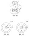
- FIG. 1Ais an isometric view of a portable power supply system and an electrically powered device according to one illustrated embodiment.
- FIG. 1Bis a bottom plan view of a portion of a power coupling structure of a portable power supply system according to one illustrated embodiment.
- FIG. 1Cis a top plan view of a portion of a power coupling structure of an electrically powered device according to one illustrated embodiment.
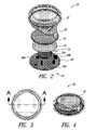
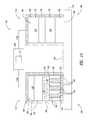
- FIG. 2is an exploded view of a portable power supply system according to one illustrated embodiment.
- FIG. 3is a top plan view of the portable power supply system of FIG. 2 according to one illustrated embodiment.
- FIG. 4is a top front isometric view of the portable power supply system of FIG. 2 according to one illustrated embodiment.
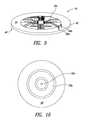
- FIG. 5Ais a cross-sectional view of a site taken along the line A-A of the portable power supply system of FIG. 3 according to one illustrated embodiment.
- FIG. 5Bis a top front isometric view of the portable power supply system including a replaceable battery according to one illustrated embodiment.
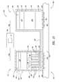
- FIG. 6is a functional block diagram showing a portable power supply system according to one illustrative embodiment.
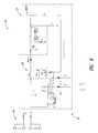
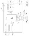
- FIG. 7is a schematic diagram of a circuit for a portable power supply system according to one illustrative embodiment.
- FIG. 8is a schematic diagram of a control circuit according to one illustrative embodiment.
- FIG. 9is a top front view of a circuit in the form of a printed circuit according to one illustrated embodiment.
- FIG. 10is a bottom plan view of a circuit in the form of a printed circuit according to one illustrated embodiment.
- FIG. 11is a top plan view of a transdermal delivery device comprising an active electrode assembly and a counter electrode assembly according to one illustrated embodiment.
- FIG. 12is a top plan view of a transdermal delivery device comprising an active electrode assembly and a counter electrode assembly according to another illustrated embodiment.
- FIG. 13is a schematic diagram of the transdermal delivery device of FIG. 11 comprising an active electrode assembly and a counter electrode assembly according to one illustrated embodiment.
- FIG. 14is a schematic diagram of the transdermal delivery device of FIG. 13 positioned on a biological interface, with an optional outer release liner removed to expose the active agent, according to another illustrated embodiment.
- FIG. 15is a schematic diagram of the transdermal delivery device comprising an active electrode assembly and a counter electrode assembly and a plurality of microneedles according to one illustrated embodiment.
- FIG. 16is a bottom front isometric view of a plurality of microneedles in the form of an array according to one illustrated embodiment.
- FIG. 17is a bottom front isometric view of a plurality of microneedles in the form of one or more arrays according to another illustrated embodiment.
- FIG. 18is a cross-sectional view of an encapsulated battery assembly for powering a transdermal delivery device according to one illustrated embodiment.
- FIG. 19is a functional block diagram showing an encapsulated battery assembly for inductively powering a transdermal delivery device according to one illustrated embodiment.
- FIG. 20is an unexploded and an exploded view of an encapsulated battery assembly for powering a transdermal delivery device according to another illustrated embodiment.
- FIG. 21is a top plan view of a transdermal delivery device according to one illustrated embodiment.
- FIG. 22is a top plan view of a transdermal delivery device according to another illustrated embodiment.
- FIG. 23is a top plan view of an encapsulated battery assembly for powering a transdermal delivery device according to another illustrated embodiment.
- FIG. 24is a top plan view of a transdermal delivery device according to one illustrated embodiment.
- FIG. 25is a top plan view of a transdermal delivery device according to one illustrated embodiment.
- FIG. 26is a top plan view of a transdermal delivery device according to one illustrated embodiment.
- FIG. 27is a top plan view of a magnetic interconnect element for a transdermal delivery device according to one illustrated embodiment.
- FIG. 28is a bottom plan view of a power supply for powering a transdermal delivery device according to one illustrated embodiment.
- FIG. 29is a bottom plan view of a power supply for powering a transdermal delivery device according to one illustrated embodiment.
- FIG. 30is a top plan view of a portion of a transdermal delivery device including a first magnetic interconnect element according to one illustrated embodiment.
- FIG. 31is a top plan view of an iontophoretic drug delivery system for providing transdermal delivery of one or more active agents according to one illustrated embodiment.
- FIG. 32is a top plan view of an iontophoretic drug delivery system for providing transdermal delivery of one or more active agents according to one illustrated embodiment.
- FIG. 33is a top plan view of a detachable controller for a transdermal drug delivery device according to another illustrated embodiment.
- FIG. 34is a top plan view of a transdermal drug delivery device according to one illustrated embodiment.
- FIG. 35is a top plan view of a detachable controller for a transdermal drug delivery device according to another illustrated embodiment.
- FIG. 36is a top plan view of a transdermal drug delivery device according to one illustrated embodiment.
- FIG. 37is an exploded view of a transdermal drug delivery device according to one illustrated embodiment.
- membranemeans a boundary, layer, barrier, or material, which may or may not be permeable.
- membranemay further refer to an interface. Unless specified otherwise, membranes may take the form of a solid, a liquid, or a gel, and may or may not have a distinct lattice, non-cross-linked structure, or cross-linked structure.
- ion selective membranemeans a membrane that is substantially selective to ions, passing certain ions while blocking passage of other ions.
- An ion selective membranefor example, may take the form of a charge selective membrane, or may take the form of a semi-permeable membrane.
- charge selective membranemeans a membrane that substantially passes and/or substantially blocks ions based primarily on the polarity or charge carried by the ion.
- Charge selective membranesare typically referred to as ion exchange membranes, and these terms are used interchangeably herein and in the claims.
- Charge selective or ion exchange membranesmay take the form of a cation exchange membrane, an anion exchange membrane, and/or a bipolar membrane.
- a cation exchange membranesubstantially permits the passage of cations and substantially blocks anions. Examples of commercially available cation exchange membranes include those available under the designators NEOSEPTA, CM-1, CM-2, CMX, CMS, and CMB from Tokuyama Co., Ltd.
- an anion exchange membranesubstantially permits the passage of anions and substantially blocks cations.
- examples of commercially available anion exchange membranesinclude those available under the designators NEOSEPTA, AM-1, AM-3, AMX, AHA, ACH, and ACS, also from Tokuyama Co., Ltd.
- bipolar membranemeans a membrane that is selective to two different charges or polarities.
- a bipolar membranemay take the form of a unitary membrane structure, a multiple membrane structure, or a laminate.
- the unitary membrane structuremay include a first portion including cation ion exchange materials or groups and a second portion opposed to the first portion, including anion ion exchange materials or groups.
- the multiple membrane structuree.g., two-film structure
- the cation and anion exchange membranesinitially start as distinct structures, and may or may not retain their distinctiveness in the structure of the resulting bipolar membrane.
- the term “semi-permeable membrane”means a membrane that is substantially selective based on a size or molecular weight of the ion.
- a semi-permeable membranesubstantially passes ions of a first molecular weight or size, while substantially blocking passage of ions of a second molecular weight or size, greater than the first molecular weight or size.
- a semi-permeable membranemay permit the passage of some molecules at a first rate, and some other molecules at a second rate different from the first.
- the “semi-permeable membrane”may take the form of a selectively permeable membrane allowing only certain selective molecules to pass through it.
- porous membranemeans a membrane that is not substantially selective with respect to ions at issue.
- a porous membraneis one that is not substantially selective based on polarity, and not substantially selective based on the molecular weight or size of a subject element or compound.
- the term “gel matrix”means a type of reservoir, which takes the form of a three-dimensional network, a colloidal suspension of a liquid in a solid, a semi-solid, a cross-linked gel, a non-cross-linked gel, a jelly-like state, and the like.
- the gel matrixmay result from a three-dimensional network of entangled macromolecules (e.g., cylindrical micelles).
- a gel matrixmay include hydrogels, organogels, and the like.
- Hydrogelsrefer to three-dimensional network of, for example, cross-linked hydrophilic polymers in the form of a gel and substantially composed of water. Hydrogels may have a net positive or negative charge, or may be neutral.
- a reservoirmeans any form of mechanism to retain an element, compound, pharmaceutical composition, active agent, and the like, in a liquid state, solid state, gaseous state, mixed state and/or transitional state.
- a reservoirmay include one or more cavities formed by a structure, and may include one or more ion exchange membranes, semi-permeable membranes, porous membranes and/or gels if such are capable of at least temporarily retaining an element or compound.
- a reservoirserves to retain a biologically active agent prior to the discharge of such agent by electromotive force and/or current into the biological interface.
- a reservoirmay also retain an electrolyte solution.
- active agentrefers to a compound, molecule, or treatment that elicits a biological response from any host, animal, vertebrate, or invertebrate, including, for example, fish, mammals, amphibians, reptiles, birds, and humans.
- active agentsinclude therapeutic agents, pharmaceutical agents, pharmaceuticals (e.g., a drug, a therapeutic compound, pharmaceutical salts, and the like) non-pharmaceuticals (e.g., a cosmetic substance, and the like), a vaccine, an immunological agent, a local or general anesthetic or painkiller, an antigen or a protein or peptide such as insulin, a chemotherapy agent, and an anti-tumor agent.
- the term “active agent”refers to the active agent as well as to its pharmacologically active salts, pharmaceutically acceptable salts, prodrugs, metabolites, analogs, and the like.
- the active agentincludes at least one ionic, cationic, ionizeable, and/or neutral therapeutic drug, and/or pharmaceutically acceptable salts thereof.
- the active agentmay include one or more “cationic active agents” that are positively charged, and/or are capable of forming positive charges in aqueous media.
- many biologically active agentshave functional groups that are readily convertible to a positive ion or can dissociate into a positively charged ion and a counter ion in an aqueous medium.
- active agentsmay be polarized or polarizable, that is exhibiting a polarity at one portion relative to another portion.
- an active agent having an amino groupcan typically take the form an ammonium salt in solid state and dissociates into a free ammonium ion (NH4 + ) in an aqueous medium of appropriate pH.
- active agentmay also refer to electrically neutral agents, molecules, or compounds capable of being delivered via electro-osmotic flow.
- the electrically neutral agentsare typically carried by the flow of, for example, a solvent during electrophoresis. Selection of the suitable active agents is therefore within the knowledge of one skilled in the relevant art.
- one or more active agentsmay be selected from analgesics, anesthetics, anesthetics vaccines, antibiotics, adjuvants, immunological adjuvants, immunogens, tolerogens, allergens, toll-like receptor agonists, toll-like receptor antagonists, immuno-adjuvants, immuno-modulators, immuno-response agents, immuno-stimulators, specific immuno-stimulators, non-specific immuno-stimulators, and immuno-suppressants, or combinations thereof.
- Non-limiting examples of such active agentsinclude lidocaine, articaine, and others of the -caine class; morphine, hydromorphone, fentanyl, oxycodone, hydrocodone, buprenorphine, methadone, and similar opioid agonists; sumatriptan succinate, zolmitriptan, naratriptan HCl, rizatriptan benzoate, almotriptan malate, frovatriptan succinate and other 5-hydroxytryptaminel receptor subtype agonists; resiquimod, imiquidmod, and similar TLR 7 and 8 agonists and antagonists; domperidone, granisetron hydrochloride, ondansetron and such anti-emetic drugs; zolpidem tartrate and similar sleep inducing agents; L-dopa and other anti-Parkinson's medications; aripiprazole, olanzapine, quetiapine, risperidone,
- active agentsinclude ambucaine, amethocaine, isobutyl p-aminobenzoate, amolanone, amoxecaine, amylocalne, aptocaine, azacaine, bencaine, benoxinate, benzocaine, N,N-dimethylalanylbenzocaine, N,N-dimethylglycylbenzocaine, glycylbenzocaine, beta-adrenoceptor antagonists betoxycaine, bumecaine, bupivicaine, levobupivicaine, butacaine, butamben, butanilicaine, butethamine, butoxycaine, metabutoxycaine, carbizocaine, carticaine, centbucridine, cepacaine, cetacaine, chloroprocaine, cocaethylene, cocaine, pseudococaine, cyclomethycaine, dibucaine, dimethisoquin, dimethocaine, dip
- subjectgenerally refers to any host, animal, vertebrate, or invertebrate, and includes fish, mammals, amphibians, reptiles, birds, and particularly humans.
- agonistrefers to a compound that can combine with a receptor (e.g., an opioid receptor, toll-like receptor, and the like) to produce a cellular response.
- a receptore.g., an opioid receptor, toll-like receptor, and the like
- An agonistmay be a ligand that directly binds to the receptor.
- an agonistmay combine with a receptor indirectly by forming a complex with another molecule that directly binds the receptor, or otherwise results in the modification of a compound so that it directly binds to the receptor.
- an antagonistrefers to a compound that can combine with a receptor (e.g., an opioid receptor, a toll-like receptor, and the like) to inhibit a cellular response.
- a receptore.g., an opioid receptor, a toll-like receptor, and the like
- An antagonistmay be a ligand that directly binds to the receptor.
- an antagonistmay combine with a receptor indirectly by forming a complex with another molecule that directly binds to the receptor, or otherwise results in the modification of a compound so that it directly binds to the receptor.
- the term “effective amount” or “therapeutically effective amount”includes an amount effective at dosages and for periods of time necessary, to achieve the desired result.
- the effective amount of a composition containing a pharmaceutical agentmay vary according to factors such as the disease state, age, gender, and weight of the subject.
- analgesicrefers to an agent that lessens, alleviates, reduces, relieves, or extinguishes a neural sensation in an area of a subject's body.
- the neural sensationrelates to pain, in other aspects the neural sensation relates to discomfort, itching, burning, irritation, tingling, “crawling,” tension, temperature fluctuations (such as fever), inflammation, aching, or other neural sensations.
- the term “anesthetic”refers to an agent that produces a reversible loss of sensation in an area of a subject's body.
- the anestheticis considered to be a “local anesthetic” in that it produces a loss of sensation only in one particular area of a subject's body.
- agentsmay act as both an analgesic and an anesthetic, depending on the circumstances and other variables including but not limited to dosage, method of delivery, medical condition or treatment, and an individual subject's genetic makeup. Additionally, agents that are typically used for other purposes may possess local anesthetic or membrane stabilizing properties under certain circumstances or under particular conditions.
- immunogenrefers to any agent that elicits an immune response.
- immunogeninclude but are not limited to natural or synthetic (including modified) peptides, proteins, lipids, oligonucleotides (RNA, DNA, etc.), chemicals, or other agents.
- allergenrefers to any agent that elicits an allergic response.
- allergensinclude but are not limited to chemicals and plants, drugs (such as antibiotics, serums), foods (such as milk, wheat, eggs, etc), bacteria, viruses, other parasites, inhalants (dust, pollen, perfume, smoke), and/or physical agents (heat, light, friction, radiation).
- drugssuch as antibiotics, serums
- foodssuch as milk, wheat, eggs, etc
- bacteriaviruses, other parasites
- inhalantsdust, pollen, perfume, smoke
- physical agentsheat, light, friction, radiation
- adjuvantrefers to an agent that modifies the effect of another agent while having few, if any, direct effects when given by itself.
- an adjuvantmay increase the potency or efficacy of a pharmaceutical, or an adjuvant may alter or affect an immune response.
- opioidgenerally refers to any agent that binds to and/or interacts with opioid receptors.
- opioid classesinclude endogenous opioid peptides, opium alkaloids (e.g., morphine, codeine, and the like), semi-synthetic opioids (e.g., heroin, oxycodone and the like), synthetic opioids (e.g., buprenorphinemeperidine, fentanyl, morphinan, benzomorphan derivatives, and the like), as well as opioids that have structures unrelated to the opium alkaloids (e.g., pethidine, methadone, and the like).
- the terms “vehicle,” “carrier,” “pharmaceutical vehicle,” “pharmaceutical carrier,” “pharmaceutically acceptable vehicle,” or “pharmaceutically acceptable carrier”may be used interchangeably, and refer to pharmaceutically acceptable solid or liquid, diluting or encapsulating, filling or carrying agents, which are usually employed in the pharmaceutical industry for making pharmaceutical compositions.
- vehiclesinclude any liquid, gel, salve, cream, solvent, diluent, fluid ointment base, vesicle, liposome, nisome, ethasomes, transfersome, virosome, non-ionic surfactant vesicle, phospholipid surfactant vesicle, micelle, and the like, that is suitable for use in contacting a subject.
- the pharmaceutical vehiclemay refer to a composition that includes and/or delivers a pharmacologically active agent, but is generally considered to be otherwise pharmacologically inactive.
- the pharmaceutical vehiclemay have some therapeutic effect when applied to a site such as a mucous membrane or skin, by providing, for example, protection to the site of application from conditions such as injury, further injury, or exposure to elements. Accordingly, in some embodiments, the pharmaceutical vehicle may be used for protection without a pharmacological agent in the formulation.
- FIGS. 1A , 1 B, and 1 Cshow an exemplary portable power supply system 10 for providing power to an electrically powered device 11 (e.g., an iontophoretic delivery device, a transdermal patch, an active agent delivery device, and the like).
- an electrically powered device 11e.g., an iontophoretic delivery device, a transdermal patch, an active agent delivery device, and the like.
- the portable power supply system 10may include one or more physical coupling structures 3 for physically coupling the portable power supply system 10 to the electrically powered device 11 .
- the one or more physical coupling structures 3may take a variety of forms.
- the physical coupling structuremay include one or more distinct elements 3 a , 3 b .
- the physical coupling structuremay include one or more couplers, fasteners, connectors, inter-connectors, polarized connectors, hook and loop type fasteners, snap-fitting type fasteners, snap type fasteners, friction fit type fasteners, detent elements, magnetic couplers, magnetic connectors, and the like.
- the physical coupling structures 3may take the form of a magnetic physical coupling structure 12 .
- such magnetic physical coupling structure 12may include a number of distinct elements, for instance, one or more permanent magnets, one or more ferrous, ferromagnetic, or ferrimagnetic elements or coatings and/or one or more electromagnets.
- the portable power supply system 10may be permanently physically coupled (i.e., directly or indirectly) to the electrically powered device 11 .
- the portable power supply system 10may be releasably physically coupled to the electrically powered device 11 via one or more physical coupling structures 3 .
- the portable power supply system 10is also coupled to provide power to the electrically powered device 11 via one or more power coupling structures 5 , for example, via electrical, inductive and/or capacitive coupling.
- the portable power supply system 10 and the electrically powered device 11may include one or more power coupling structures for electrically, inductive, and/or capacitive coupling the portable power supply system 10 to the electrically powered device 11 .
- the one or more power coupling structures 5may take a variety of forms.
- the power coupling structures 5may include one or more distinct elements 5 a , 5 b .
- the power coupling structures 5may include one or more contacts, leads, terminals, inductors, or plates, which are or may be positioned with respect to one another to effectively transfer power between the portable power supply system 10 and the electrically powered device 11 .
- Such transfer of powermay be, for example, electrically or conductively, inductively or capacitively.
- the power coupling structure 5may take the form of one or more electrical coupling structures 5 a , 5 b , for electrically coupling the portable power supply system 10 to the electrically powered device 11 .
- the electrical coupling structures 5 a , 5 b examplesinclude one or more contacts, leads, terminals, inductors, plates, polarized coupling elements, multi-pin connectors, DIN connectors, polarized multi-pin connectors, circular connectors, slot type interconnectors, and the like, which are or may be positioned with respect to one another to effectively transfer power between the portable power supply system 10 and the electrically powered device 11 .
- the one or more electrical coupling structures 5 a of the portable power supply system 10are configured to electrically couple to the corresponding one or more electrical coupling structures 5 b of the electrically powered device 11 in correct electrical polarity.
- the one or more power coupling structures 5may take the form of polarized (configured to provide corresponding electrical polarity coupling elements) power coupling elements that prevent incorrect or reversed power coupling of the portable power supply system 10 to the electrically powered device 11 .
- one or more electrical coupling structures 6 , 8 of the portable power supply system 10are configured to electrically couple to the corresponding one or more electrical coupling structures 7 , 9 of the electrically powered device 11 with no electrical shorting between the electrical coupling structures 6 , 8 of the portable power supply system 10 and the electrical coupling structures 7 , 9 of the electrically powered device 11 .
- the spacing between the electrical contacts 6 , 8 of the portable power supply system 10 , as well as the spacing between the electrical contacts 7 , 9 of the electrically powered device 11precludes shorting when the portable power supply system 10 is physically coupled to the electrically powered device 11 by the physical coupling structure 3 .
- the one or more physical coupling structures 3are configured to retain the portable power supply system 10 in a position and/or orientation that ensures a correct polarity between power (e.g., electrical, inductive or capacitive) coupling structures 5 a (e.g., contacts, terminals or leads and the like) of the portable power supply system 10 and power coupling structures 5 b of the electrically powered device 11 .
- powere.g., electrical, inductive or capacitive
- an electrical coupling structure 6 of a first polarity of the portable power supply system 10is configured to electrically couple to the corresponding power coupling structure 7 of the first polarity of the electrically powered device 11
- an electrical coupling structure 8 of a second polarity, opposite to the first polarity, of the portable power supply system 10is configured to electrically couple to the corresponding electrical coupling structure 9 of the second polarity of the electrically powered device 11 , with no electrical shorting.
- the power coupling structures 6 , 8 and 7 , 9take the form of two or more electrical contacts 6 a , 8 a and 7 a , 9 a respectively, each respectively forming a concentric geometric pattern that provides universally oriented proper electrical polarity alignment of the electrical contacts 6 a , 8 a and 7 a , 9 a.
- the concentric patternform by, for example, electrical contacts 6 a , 8 a , as well as by electrical contacts 7 a , 9 a , creates an enhanced “target” message for a user coupling the portable power supply system 10 to the electrically powered device 11 .
- FIGS. 2 through 5Bshow an exemplary portable power supply system 10 for providing power to the electrically powered device 11 .
- the portable power supply system 10includes a coupling element 12 configured to physical couple the portable power supply system 10 to the electrically powered device 11 , and a power source 14 .
- the portable power supply system 10may further include a circuit 16 .
- the power supply system 10includes at least one of a cover 18 , a power source holder 20 , and a power source contact 22 .
- the coupling element 12is magnetically-releasably attachable to the electrically powered device 11 .
- the coupling element 12takes the form of a first magnetic coupling element 12 a coupled to the power source 14 .
- the first magnetic coupling element 12 ais magnetically-releasably attachable to the electrically powered device 11 such that the power source 14 is operable to provide electrical power to the electrically powered device 11 in response to the portable power supply system 10 being magnetically coupled to the electrically powered device 11 by the first magnetic coupling element 12 a.
- a suitable first magnetic coupling element 12 aexamples include permanent magnets, one or more ferrous, ferromagnetic, or ferrimagnetic elements or coatings and/or one or more electromagnets.
- a suitable first magnetic coupling element 12 aincludes at least one of a paramagnetic material element, a ferromagnetic material element, ferromagnetic coatings (e.g., ferrous paint), magnetic coatings (e.g., magnetic paint), and the like.
- Paramagnetic materialstypically have a small and positive susceptibility (a relative magnetic permeability greater than unity) to magnetic fields and are attracted to a magnetic field (e.g., a magnet).
- Ferromagnetic materialse.g., cobalt, iron, nickel, gadolinium, steel, and the like
- the first coupling element 12 amay take the form of at least one ferrous metal element.
- the ferrous metal elementmay, in some embodiments, magnetically-releasably attach the portable power supply system 10 to a magnet (e.g., a permanent magnet, and the like) carried by the electrically powered device 11 .
- the first magnetic coupling element 12 atakes the form of at least one permanent magnet.
- the at least one permanent magnetmay, in some embodiments, magnetically-releasably attach the portable power supply system 10 to a paramagnetic material element, a ferromagnetic material element, and the like, carried by the electrically powered device 11 .
- the at least one permanent magnetexamples include high-energy flexible magnets, neodymium magnets, ceramic magnets, samarium cobalt magnets, alnico magnets, rare earth magnets, and the like.
- the first magnetic coupling element 12 amay further be electrically conductive and electrically coupleable to a first pole of the power source 14 .
- the second magnetic coupling elementmay further be electrically conductive and electrically coupleable to a second pole of the power source 14
- the portable power supply system 10may further include a second magnetic coupling element physically coupled to the power source 14 .
- the second magnetic coupling elementis operable to releasably attach the portable power supply system 10 to the electrically powered device 11 .
- the second magnetic coupling elementmay further be electrically conductive and electrically coupleable to a second pole of the power source 14 .
- the second magnetic coupling elementis configured to releasably retain the portable power supply system 10 in a correct electrical polarity with respect to the electrically powered device 11 .
- the second magnetic coupling elementhas a magnetic polarity opposite a magnetic polarity of the first magnetic coupling element 12 a .
- Examples of a suitable second magnetic coupling element 12 ainclude permanent magnets, one or more ferrous, ferromagnetic, or ferrimagnetic elements or coatings and/or one or more electromagnets.
- a suitable second magnetic coupling element 12 aincludes at least one of a paramagnetic material element, a ferromagnetic material element, ferromagnetic coatings (e.g., ferrous paint), magnetic coatings (e.g., magnetic paint), and the like.
- the power source 14is operable to provide electrical power to power the electrically powered device 11 in response to the portable power supply system 10 being coupled to the electrically powered device 11 .
- the electrically powered device 11include medical devices, transdermal delivery devices (e.g., iontophoretic delivery devices), and the like.
- the power source 14takes the form of at least one chemical battery cell, an ultra-capacitor, a fuel, and the like.
- the power source 14takes the form of at least one primary cell or secondary cell.
- power source 14examples include at least one of a button cell, a coin cell, an alkaline cell, a lithium cell, a lithium ion cell, a zinc air cell, a nickel metal hydride cell, and the like.
- the power source 14takes the form of at least one printed battery, energy cell laminate, thin-film battery, power paper, and the like, or combinations thereof.
- the portable power supply system 10may releasably attach and/or releasably coupled to the electrically powered device 11 using, for example, a physical coupling structure.
- the physical coupling structuremay include a ferrous paint element releasably attachable and/or releasably coupled to a magnetic substrate.
- the physical coupling structuremay include a ferrous substrate releasably attachable and/or releasably coupled to a magnetic substrate.
- the physical coupling structuremay include a ferrous substrate releasably attachable and/or releasably coupled to a magnetic paint element.
- the physical coupling structuremay include a ferrous paint element releasably attachable and/or releasably coupled to a magnetic paint element.
- the physical coupling structuremay include a hook and loop fastener physical coupling structure.
- the physical coupling structuremay include a multi-part EKG/ECG type interconnect using, for example, concentrically patterned fasteners.
- the physical coupling structuremay include a slot type physical coupling structure.
- the portable power supply system 10may include a replaceable power source 14 .
- substrate 42may be detachably affixed to the cover 18 such that the substrate 42 is movable between an open position (as shown in FIG. 5B ) and a close position (as shown in FIG. 5A ).
- the opened positionthe interior 18 a of the cover 18 may be accessible from the exterior 18 b of the cover 18 , allowing for the placement, removal, or replacement of the power source 14 .
- the closed positionthere may be limited access to the interior of the cover 18 .
- the substrate 42may be detachably affixed to the cover 18 using one or more couplers, fasteners, friction-fit structures, thread-coupled structures, bayonet-coupled structures, and the like.
- the substrate 42may be thread-coupled to the cover 18 .
- substrate 42can be detached from to the cover 18 to allow for the placement, removal, or replacement of the power source 14 .
- substrate 42may be disengaged from the cover 18 allowing for the placement, removal, or replacement of the power source 14 carried within.
- substrate 42may include a notch 42 structure to facilitate the prying or disengaging of substrate 42 from the cover 18 and allowing for the placement, removal, or replacement of the power source 14 .
- substrate 42may include a tab structure to facilitate the prying or disengaging of substrate 42 from the cover 18 and allowing for the placement, removal, or replacement of the power source 14 .
- the portable power supply system 10may also include a control system in the form of a control circuit 16 to control the voltage, current, and/or power delivered to the electrically powered device 11 .
- the control circuit 16may include one or more controllers 24 such as a microprocessor, a digital signal processor (DSP) (not shown), an application-specific integrated circuit (ASIC) (not shown), and the like.
- the control circuit 16may also include one or more memories, for example, read-only memory (ROM) 26 , random access memory (RAM) 28 , and the like, coupled to the controllers 24 by one or more busses 30 .
- the control circuit 16may further include one or more input devices 32 (e.g., a display, touch-screen display, and the like).
- the control circuit 16may also include discrete and/or integrated circuit elements 36 a , 36 b , 36 c to control the voltage, current, and/or power.
- the control circuit 16may include a diode to provide a constant current to the electrically powered device 11 .
- the control circuit 16may include a rectifying circuit element to provide a direct current voltage and/or a voltage/current regulator.
- the control circuit 16sinks and sources voltage to maintain a steady state operation of the electrically powered device 11 .
- the control circuit 16may be electrically coupled to receive current from the power source 14 , via electrical contacts 15 .
- the control circuit 16may take the form of a programmable control circuit operable to provide at least a first current profile.
- control circuit 16may take the form of a programmable control circuit operable to provide a plurality of current profiles.
- the control circuit 16may be operable to provide at least a first current profile associated with the control delivery, sustained delivery, and the like, associated with transdermal delivery of one or more active agents to a biological interface of a subject.
- control circuit 16is configured to track, store, transmit, receive, and/or retrieve treatment management data.
- control circuit 16may be configured to track, store, transmit, receive, and/or retrieve transdermal delivery device information.
- control circuit 16may be configured to query tag data (e.g., a Radio Frequency Identification (RFID) tag) including for example stored data codes, user data, patient data, drug delivery device data, and the like.
- RFIDRadio Frequency Identification
- control circuit 16is configured to store and/or track historical data, use data, patient data, and the like.
- control circuit 16includes an RFID type chip to store, track, receive, and retrieve delivery device (e.g., iontophoretic delivery device, transdermal patch, and the like) information, query tag data, store data codes, track use data, track patient data, and the like.
- the RFID type chipmay take the form of, for example, an active type RFID type chip, receiving power form the portable power supply system 10 .
- the RFID type chipmay take the form of a passive type RFID type chip using, for example, only a memory portion of RFID type chip.
- a portion of the RFID type chipis used for memory without using the RF capabilities of the RFID type chip. Such may advantageously take advantage of low cost chips produced for high volume applications such as RFID.
- the control circuit 16is configured to automatically close (e.g., via circuit element 17 ) in response to the portable power supply system 10 being releasably attached to the electrically powered device 11 .
- the control circuit 16may include a switch 34 selectively operable to control a supply of current to the electrically powered device 11 in response to the portable power supply system 10 being releasably attached to the electrically powered device 11 .
- the switch 34is selectively operable to automatically close in response to the portable power supply system 10 being releasably attached to the electrically powered device 11 .
- the control circuit 16may further include self-test capabilities that are initiated once the control circuit 16 is closed.
- the control circuit 16may further include a start and/or stop switch 38 for selectively controlling the flow of current to the control circuit 16 .
- the switch 38may take the form of a dome switch, a membrane switch, a tactile switch, a single-use dome switch, a single-use membrane switch, a single-use tactile switch, and the like.
- control circuit 16may be operable to detect a power source polarity and provide a charge of a proper polarity to respective ones of a positive electrical contact and a negative electrical contact of the electrically powered device, in response to the portable power supply system 10 being releasably attached to the electrically powered device 11 .
- the portable power supply system 10may further include one or more indicators 40 to, for example, alert a user that the portable power supply system 10 is operating properly.
- the one or more indicators 40include visual feedback elements 40 a (e.g., light-emitting diodes (LEDs) (e.g., green LEDs and red LEDs), a display, and the like), audio feedback elements 40 b (e.g., an alarm), and the like.
- LEDslight-emitting diodes
- audio feedback elements 40 be.g., an alarm
- the portable power supply system 10has a largest dimension of less than about 25 mm, and a smallest dimension of less than about 10 mm. In some embodiments, the portable power supply system 10 has an aspect ratio ranging from about 2:1 to about 13:1.
- FIG. 8shows a control circuit 16 , according to one illustrated embodiment.
- the control circuit 16includes a number of input terminals 19 , a number of output terminals 21 , a regulation circuit 23 coupled between the input and output terminals 19 , 21 , a number of indicators D 3 -D 6 , and a controller U 2 .
- the input terminals 19provide a structure to electrically couple the control circuit 16 to a power source, for example a chemical battery cell.
- the control circuit 16may include three input terminals B 1 -B 3 of a first polarity and three input terminals M 1 -M 3 of a second polarity. Such may ensure good electrical contact with the power source 14 , although some embodiments may employ a lesser or greater number of input terminals.
- the output terminals 21provide a structure to supply electrical power to electrodes of an active agent delivery device, for example an iontophoresis patch.
- the output terminals 21may comprise a first and a second terminal, one for each polarity.
- the output terminals 21may be configured, shaped, and/or arranged to assure that the correct polarity is maintained when coupling, for example, the portable power supply system 10 to the electrically powered device 11 .
- the output terminals 21may be formed as two concentric structures, for example, an inner pad and an outer annulus or ring surrounding the inner pad.
- the inner padmay take the form of an annulus or ring shape, however other shapes are possible.
- the other structuremay be a shape other than an annulus or ring.
- one of the output terminals 21may substantially or completely surround in the other output terminal 21 , while in other embodiments, one of the output terminals 21 may only partially surround or may not even partially surround the other input terminal 19 .
- the regulation circuit 23includes a power converter 25 operable to adjust or maintain a current and/or voltage at the output terminals 21 , for example, as discussed in detail below.
- the power converter 25may take the form of current regulator, boost converter, buck converter, or some combination of the same.
- the regulation circuit 23may take the form of a boost converter formed, for example, by an inductor L 1 coupled between the input and output terminals of a switch Q 1 operable to selectively couple the inductor L 1 to ground.
- the switch Q 1may take the form of a transistor having a gate, a drain, and a source.
- the control circuit 16may include a Schottky diode D 1 to prevent damage in the event of a reversal of polarity.
- the control circuit 16may include a Zener diode D 7 coupled to ground to prevent output voltage from exceeding a desired level.
- the control circuit 16may also include an input capacitor C 1 coupled to ground, between the output terminals 21 and the inductor L 1 to act as an input filter.
- the control circuit 16may further include an output capacitor C 2 coupled to ground, between the inductor L 1 and the output terminals 21 to act as an output filter, reducing ripple in the output current.
- the controller U 2may take a variety of forms, for example a microcontroller, processor, microprocessor, digital signal processor, field programmable gate array, or the like.
- the controller U 2includes power and ground connectors or pins VDD, VSS.
- the controller U 2supplies drive signals to the gate of the transistor Q 1 via output or pin 3 of the controller U 2 .
- Inputs or pins 1 , 6 of the controller U 2are coupled to terminals 1 , 2 of the output terminals 21 , respectively.
- the controller U 2can determine or sense the operating characteristics at the output terminals 21 .
- the controller U 2may be responsive to the presence or absence of a load across the output terminals 21 via a load sense resistor R 12 .
- the value of R 12may be selected such that the impedance associated with skin or other biological tissue (e.g., 20 K Ohms) is sufficient to trigger the controller U 2 .
- the controller U 2may also be responsive to a measure of voltage across and/or flow of current at the output terminals 21 .
- the controller U 2is responsive to a measure of current via a current sense resistor R 15 .
- the controller U 2may be normally powered and/or in the ON state, and may be programmed or otherwise configured to perform certain functions upon detection or in response to a load across the output terminals 21 via load sense resistor R 12 .
- the controller U 2may be configured or programmed to perform one or more tests, provide appropriate indications, and/or take appropriate actions based on the results of the tests, and/or start delivery active agent according to one or more delivery profiles.
- the controller U 2may enter a test or startup mode upon detection of a load, and may enter a current supply mode upon successful completion of the test and startup mode.
- the controller U 2may be in a wait or sleep mode prior to detecting a load, for example, while the portable power supply system 10 is in storage.
- An energy efficient controller U 2may be stored for many years while monitoring for the presence of the load.
- the controller U 2may be programmed or otherwise configured to employ a measure of voltage across, or current through, the output terminals 21 to maintain a desired delivery profile, for example, a constant current delivery profile.
- the controller U 2may provide drive signals to maintain a constant, or approximately constant, current output at the output terminals 21 over at least a portion of a delivery profile.
- the controller U 2may provide drive signals to provide an increasing current output at the output terminals 21 over at least a portion of a delivery profile.
- the controller U 2may provide drive signals to produce an increasing current over an initial portion of a delivery profile.
- the increasing currentmay increase linearly or nonlinearly.
- the controller U 2may provide drive signals to produce an increasing current over a terminal portion of a delivery profile.
- the controller U 2may provide drive signals to provide a varying current output at the output terminals 21 over at least a portion of a delivery profile.
- the controller U 2may provide drive signals to produce a varying current over an initial portion of a delivery profile, terminal portion of a delivery profile or some intermediate portion of a delivery profile.
- the currentmay vary periodically, for example sinusoidally, or may vary aperiodically.
- the controller U 2sets a duty cycle of a drive signal supplied to the gate of the transistor Q 1 in order to maintain a constant current output at the output terminals 21 .
- the controller U 2may start with a low duty cycle, increasing the duty cycle until a voltage supplied at pin 1 via the current sense resistor R 15 matches a reference voltage V ref .
- the reference voltage V refmay be stored or defined internally in the controller U 2 , and may, for example be approximately 0.6V.
- the controller U 2may oscillate, or vary, the duty cycle to maintain the desired constant current operation.
- the indicators D 5 , D 6may take the form of two or more light emitting diodes (LEDs) D 5 , D 6 electrically coupled in series.
- the two or more LEDs D 5 , D 6may be electrically coupled in parallel with a resistor R 11 .
- the LEDs D 5 , D 6may both produce the same color(s), when driven to emission, for example green (or green light). When lit, the LEDs D 5 , D 6 indicate that current is flowing to the output terminals.
- the indicators D 3 , D 4may take the form of LEDs D 3 , D 4 .
- the LED D 3 and the LED D 4are each electrically coupled between an output of the controller U 2 , and ground through respective resistors R 6 , R 7 .
- the LEDs D 3 , D 4may both produce the same color(s), when driven to emission.
- the LEDs D 3 , D 4may produce, for example, a color different from the color produced by the LEDs D 5 , D 6 .
- the LEDs D 3 , D 4may produce red or orange light.
- the LEDs D 3 , D 4may provide a first indication during start up, or to indicate a proper start up (e.g., blinking a predetermined number of times).
- the LEDs D 3 , D 4may provide a first indication during shut down, to indicate the delivery profile is terminating or has been terminated (e.g., blinking at a predetermined rate).
- the controller U 2may be programmed or otherwise configured to measure at least one of a voltage, current, resistance, impedance, and the like, indicative of, for example, a delivery device type (e.g., iontophoretic delivery device type, transdermal patch type, drug delivery device, and the like), a drug type, a dosing regimen, and the like.
- the controller U 2may be further configured to adjust a delivery profile, for example, a current delivery profile based on the measure of at least one of a voltage, a current, a resistance, an impedance, and the like.
- the controller U 2may be programmed or otherwise configured to query the electrically powered device 11 and based on the response of the query, adjust a delivery profile, for example, a current delivery profile.
- the control circuit 16may take the form of a printed circuit 16 a on a substrate 42 having at least a first side 44 and a second side 46 opposite to the first side 44 .
- the first side 44 of substrate 42may include at least two electrical paths 48 a and 48 b for proving electrical communication between the power source 14 adjacent to the first side 44 and at least two conductive paths 50 a and 50 b on the second side 46 .
- the at least two conductive paths 50 a , 50 bare configured to provide electrical communication between the portable power supply system 10 and the respective positive and negative electrical contacts of the electrically powered device 11 .
- the at least two conductive paths 50 a , 50 bmay take the form of at least two conductive traces forming a generally concentric geometric pattern.
- the conductive tracesmay be deposited, etched, or otherwise applied to the substrate 42 .
- the conductive tracecan comprise any suitable material for making a conductive trace including conductive polymers, metallic materials, copper, gold, silver, copper coated with silver or tin, aluminum, and/or alloys or combinations thereof.
- Techniques for making the circuit 16 a on a substrate 42are well known in the art and include lithographic techniques, conductive paint silk screen techniques, metal deposition, conventional pattering techniques, laser etching, and the like.
- well-known lithographic techniquescan be use to form a conductive trace layout, onto at least the first surface 44 of the substrate 42 .
- the lithographic process for forming the conductive trace layoutmay include, for example, applying a resist film (e.g., spin-coating a photoresist film) onto the substrate, exposing the resist with an image of a circuit layout (e.g., the geometric pattern of one or more conductive traces), heat treating the resist, developing the resist, transferring the layout onto the substrate, and removing the remaining resist. Transferring the layout onto the substrate 42 may further include using techniques like subtractive transfer, etching, additive transfer, selective deposition, impurity doping, ion implantation, and the like.
- a resist filme.g., spin-coating a photore
- a first electrical contact 50 ais electrically coupleable to a first pole of the power source 14
- a second electrical contact 50 bis electrically coupleable to a second pole of the power source 14
- the first and the second electrical contacts 50 a , 50 bare positioned to make electrical contact with a set of contacts on the electrically powered device 11 in response to the portable power supply system 10 being magnetically coupled to the electrically powered device 11 via the first magnetic coupling element 12 a.
- the first electrical contact 50 ais concentrically aligned with respect to the second electrical contact 50 b . In some further embodiments, the first electrical contact 50 a is at least a portion of a circular conductive trace and the second electrical contact 50 b is at least a portion of a circular conductive trace.
- the portable power supply system 10is useful for providing power to electrically powered devices such as, for example, a transdermal delivery device 102 .
- the portable power supply system 10may include at least one inductor electrically coupled to the power source 14 and operable to inductively transfer power from the power source 14 to the electrically powered device 11 in response to the portable power supply system 10 being magnetically coupled to the electrically powered device 11 by the first magnetic coupling element 12 a .
- the portable power supply system 10takes the form of a portable power supply system.
- FIGS. 11 and 12show exemplary transdermal delivery systems 100 for delivering of one or more active agents to a subject.
- the transdermal delivery systems 100include a transdermal delivery device 102 including active and counter electrode assemblies 112 , 114 , respectively, and a portable power supply system 10 .
- the overall shape of the transdermal delivery device 102may take a variety of geometric forms including, for example, those shown in FIGS. 11 and 12 .
- the transdermal delivery device 102further includes at least a first magnetic interconnect element 108 that magnetically-releasably couples the power supply system 10 to the substrate.
- the active electrode assembly 112takes the form of a positive electrode assembly
- the counter electrode assembly 114takes the form of a negative electrode assembly
- the counter electrode assembly 114may take the form of a negative assembly
- the active electrode assembly 114may take the form of a positive electrode assembly.
- the active and counter electrode assemblies 112 , 114are electrically coupleable to the portable power supply system 10 to supply an active agent contained in the active electrode assembly 112 , via iontophoresis, to a biological interface (e.g., a portion of skin or mucous membrane).
- the transdermal delivery device 102may optionally include a backing 119 .
- the backing 119encases the transdermal delivery device 102 .
- the backing 119physically couples the transdermal delivery device 102 to a biological interface of a subject.
- the transdermal delivery system 102is configured to provide transdermal delivery of one or more therapeutic active agents to a biological interface of a subject.
- the active electrode assembly 112may further comprise, from an interior 120 to an exterior 122 of the active electrode assembly 112 : an active electrode element 124 , an electrolyte reservoir 126 storing an electrolyte 128 , an inner ion selective membrane 130 , one or more inner active agent reservoirs 134 , storing one or more active agents 316 , an optional outermost ion selective membrane 138 that optionally caches additional active agents 40 , and an optional further active agent 142 carried by an outer surface 144 of the outermost ion selective membrane 138 .
- an active electrode element 124an electrolyte reservoir 126 storing an electrolyte 128 , an inner ion selective membrane 130 , one or more inner active agent reservoirs 134 , storing one or more active agents 316 , an optional outermost ion selective membrane 138 that optionally caches additional active agents 40 , and an optional further active agent 142 carried by an outer surface 144 of the outermost ion selective membrane 138 .
- the active electrode assembly 112may comprise an optional inner sealing liner (not shown) between two layers of the active electrode assembly 112 , for example, between the inner ion selective membrane 130 and the inner active agent reservoir 134 .
- the inner sealing linerif present, would be removed prior to application of the iontophoretic device to the biological surface 118 .
- the active electrode assembly 112may further comprise an optional outer release liner 146 .
- the one or more active agent reservoirs 134are loadable with a vehicle and/or pharmaceutical composition for transporting, delivering, encapsulating, and/or carrying the one or more active agents 136 , 140 , 142 .
- the pharmaceutical compositionincludes a therapeutically effective one or more active agents 136 , 140 , 142 .
- the active electrode element 124is electrically coupleable via a first pole 116 a to the portable power supply system 10 and positioned in the active electrode assembly 112 to apply an electromotive force to transport the active agent 136 , 140 , 142 via various other components of the active electrode assembly 112 .
- the magnitude of the applied electromotive forceis generally that required to deliver the one or more active agents according to a therapeutic effective dosage protocol. In some embodiments, the magnitude is selected such that it meets or exceeds the ordinary use operating electrochemical potential of the transdermal delivery device 102 .
- the at least one active electrode element 124is operable to provide an electromotive force for driving a pharmaceutical composition comprising one or more active agents 136 , 140 , 142 from the at least one active agent reservoir 134 , to the biological interface 118 of the subject.
- the active electrode element 124may take a variety of forms.
- the active electrode element 124may advantageously take the form of a carbon-based active electrode element.
- Suchmay comprise multiple layers, for example a polymer matrix comprising carbon and a conductive sheet comprising carbon fiber or carbon fiber paper, such as that described in commonly assigned pending Japanese patent application 2004/317317, filed Oct. 29, 2004.
- the carbon-based electrodesare inert electrodes in that they do not themselves undergo or participate in electrochemical reactions.
- an inert electrodedistributes current through the oxidation or reduction of a chemical species capable of accepting or donating an electron at the potential applied to the system, (e.g., generating ions by either reduction or oxidation of water).
- Additional examples of inert electrodesinclude stainless steel, gold, platinum, capacitive carbon, or graphite.
- an active electrode of sacrificial conductive materialsuch as a chemical compound or amalgam, may also be used.
- a sacrificial electrodedoes not cause electrolysis of water, but would itself be oxidized or reduced.
- a metal/metal saltmay be employed for an anode. In such case, the metal would oxidize to metal ions, which would then be precipitated as an insoluble salt.
- An example of such anodeincludes an Ag/AgCl electrode. The reverse reaction takes place at the cathode in which the metal ion is reduced and the corresponding anion is released from the surface of the electrode.
- the electrolyte reservoir 126may take a variety of forms including any structure capable of retaining electrolyte 128 , and, in some embodiments, may even be the electrolyte 128 itself, for example, where the electrolyte 128 is in a gel, semi-solid or solid form.
- the electrolyte reservoir 126may take the form of a pouch or other receptacle, or a membrane with pores, cavities, or interstices, particularly where the electrolyte 128 is a liquid.
- the electrolyte 128comprises ionic or ionizable components in an aqueous medium, which can act to conduct current towards or away from the active electrode element.
- Suitable electrolytesinclude, for example, aqueous solutions of salts.
- the electrolyte 128includes salts of physiological ions, such as sodium, potassium, chloride, and phosphate.
- the one or more electrolyte reservoirs 124include an electrolyte 128 comprising at least one biologically compatible anti-oxidant selected from ascorbate, fumarate, lactate, and malate, or salts thereof.
- the electrolyte 128may further comprise an anti-oxidant.
- the anti-oxidantis selected from anti-oxidants that have a lower potential than that of, for example, water. In such embodiments, the selected anti-oxidant is consumed rather than having the hydrolysis of water occur.
- an oxidized form of the anti-oxidantis used at the cathode and a reduced form of the anti-oxidant is used at the anode.
- biologically compatible anti-oxidantsinclude, but are not limited to, ascorbic acid (vitamin C), tocopherol (vitamin E), or sodium citrate.
- the electrolyte 128may take the form of an aqueous solution housed within a reservoir 126 , or may take the form of a dispersion in a hydrogel or hydrophilic polymer capable of retaining a substantial amount of water.
- a suitable electrolytemay take the form of a solution of 0.5 M disodium fumarate: 0.5 M polyacrylic acid: 0.15 M anti-oxidant.
- the inner ion selective membrane 130is generally positioned to separate the electrolyte 128 and the inner active agent reservoir 134 , if such a membrane is included within the device.
- the inner ion selective membrane 130may take the form of a charge selective membrane.
- the inner ion selective membrane 130may take the form of an anion exchange membrane, selective to substantially pass anions and substantially block cations.
- the inner ion selective membrane 130may advantageously prevent transfer of undesirable elements or compounds between the electrolyte 128 and the inner active agent reservoir 134 .
- the inner ion selective membrane 130may prevent or inhibit the transfer of sodium (Na + ) ions from the electrolyte 128 , thereby increasing the transfer rate and/or biological compatibility of the transdermal delivery device 102 .
- the inner active agent reservoir 134is generally positioned between the inner ion selective membrane 130 and the outermost ion selective membrane 138 .
- the inner active agent reservoir 134may take a variety of forms including any structure capable of temporarily retaining active agent 136 .
- the inner active agent reservoir 134may take the form of a pouch or other receptacle, or a membrane with pores, cavities, or interstices, particularly where the active agent 136 is a liquid.
- the inner active agent reservoir 134further may comprise a gel matrix.
- an outermost ion selective membrane 138is positioned generally opposed across the active electrode assembly 112 from the active electrode element 124 .
- the outermost membrane 138may, as in the embodiment illustrated in FIGS. 13 and 14 , take the form of an ion exchange membrane having pores 148 (only one called out in FIGS. 13 and 14 for sake of clarity of illustration) of the ion selective membrane 138 including ion exchange material or groups 150 (only three called out in FIGS. 13 and 14 for sake of clarity of illustration).
- the ion exchange material or groups 150selectively substantially passes ions of the same polarity as active agent 136 , 140 , while substantially blocking ions of the opposite polarity.
- the outermost ion exchange membrane 138is charge selective.
- the active agent 136 , 140 , 142is a cation (e.g., lidocaine)
- the outermost ion selective membrane 138may take the form of a cation exchange membrane, thus allowing the passage of the cationic active agent while blocking the back flux of the anions present in the biological interface, such as skin.
- the outermost ion selective membrane 138may optionally cache active agent 140 .
- the ion exchange groups or material 150temporarily retains ions of the same polarity as the polarity of the active agent in the absence of electromotive force or current and substantially releases those ions when replaced with substitutive ions of like polarity or charge under the influence of an electromotive force or current.
- the outermost ion selective membrane 138may take the form of a semi-permeable or microporous membrane that is selective by size.
- a semi-permeable membranemay advantageously cache active agent 140 , for example by employing the removably releasable outer release liner to retain the active agent 140 until the outer release liner is removed prior to use.
- the outermost ion selective membrane 138may be optionally preloaded with the additional active agent 140 , such as ionized or ionizable drugs or therapeutic agents and/or polarized or polarizable drugs or therapeutic agents. Where the outermost ion selective membrane 138 is an ion exchange membrane, a substantial amount of active agent 140 may bond to ion exchange groups 150 in the pores, cavities or interstices 148 of the outermost ion selective membrane 138 .
- active agent 140such as ionized or ionizable drugs or therapeutic agents and/or polarized or polarizable drugs or therapeutic agents.
- the active agent 142 that fails to bond to the ion exchange groups of material 150may adhere to the outer surface 144 of the outermost ion selective membrane 138 as the further active agent 142 .
- the further active agent 142may be positively deposited on and/or adhered to at least a portion of the outer surface 144 of the outermost ion selective membrane 138 , for example, by spraying, flooding, coating, electrostatically depositing, vapor depositioning, and/or otherwise.
- the further active agent 142may sufficiently cover the outer surface 144 and/or be of sufficient thickness to form a distinct layer 152 .
- the further active agent 142may not be sufficient in volume, thickness, or coverage as to constitute a layer in a conventional sense of such term.
- the active agent 142may be deposited in a variety of highly concentrated forms such as, for example, solid form, nearly saturated solution form, or gel form. If in solid form, a source of hydration may be provided, either integrated into the active electrode assembly 112 , or applied from the exterior thereof just prior to use.
- the active agent 136 , additional active agent 140 , and/or further active agent 142may be identical or similar compositions or elements. In other embodiments, the active agent 136 , additional active agent 140 , and/or further active agent 142 may be different compositions or elements from one another. Thus, a first type of active agent may be stored in the inner active agent reservoir 134 , while a second type of active agent may be cached in the outermost ion selective membrane 138 . In such an embodiment, either the first type or the second type of active agent may be deposited on the outer surface 144 of the outermost ion selective membrane 138 as the further active agent 142 .
- a mix of the first and the second types of active agentmay be deposited on the outer surface 144 of the outermost ion selective membrane 138 as the further active agent 142 .
- a third type of active agent composition or elementmay be deposited on the outer surface 144 of the outermost ion selective membrane 138 as the further active agent 142 .
- a first type of active agentmay be stored in the inner active agent reservoir 134 as the active agent 136 and cached in the outermost ion selective membrane 138 as the additional active agent 140
- a second type of active agentmay be deposited on the outer surface 144 of the outermost ion selective membrane 138 as the further active agent 142 .
- the active agents 136 , 140 , 142will all be of common polarity to prevent the active agents 136 , 140 , 142 from competing with one another. Other combinations are possible.
- the outer release linermay generally be positioned overlying or covering further active agent 142 carried by the outer surface 144 of the outermost ion selective membrane 138 .
- the outer release linermay protect the further active agent 142 and/or outermost ion selective membrane 138 during storage, prior to application of an electromotive force or current.
- the outer release linermay be a selectively releasable liner made of waterproof material, such as release liners commonly associated with pressure sensitive adhesives.
- An interface-coupling medium(not shown) may be employed between the electrode assembly and the biological interface 118 .
- the interface-coupling mediummay take, for example, the form of an adhesive and/or gel.
- the gelmay take the form of, for example, a hydrating gel. Selection of a suitable bioadhesive gels is within the knowledge of one skilled in the relevant art.
- the counter electrode assembly 114comprises, from an interior 164 to an exterior 166 of the counter electrode assembly 114 : a counter electrode element 168 , an electrolyte reservoir 170 storing an electrolyte 172 , an inner ion selective membrane 174 , an optional buffer reservoir 176 storing buffer material 178 , an optional outermost ion selective membrane 180 , and an optional outer release liner 182 .
- the counter electrode element 168is electrically coupleable via a second pole 116 b to the portable power supply system 10 , the second pole 116 b having an opposite polarity to the first pole 116 a .
- the counter electrode element 168is an inert electrode.
- the counter electrode element 168may take the form of the carbon-based electrode element discussed above.
- the electrolyte reservoir 170may take a variety of forms including any structure capable of retaining electrolyte 172 , and, in some embodiments, may even be the electrolyte 172 itself, for example, where the electrolyte 172 is in a gel, semi-solid or solid form.
- the electrolyte reservoir 170may take the form of a pouch or other receptacle, or a membrane with pores, cavities, or interstices, particularly where the electrolyte 172 is a liquid.
- the electrolyte 172is generally positioned between the counter electrode element 168 and the outermost ion selective membrane 180 , proximate the counter electrode element 168 .
- the electrolyte 172may provide ions or donate charges to prevent or inhibit the formation of gas bubbles (e.g., hydrogen or oxygen, depending on the polarity of the electrode) on the counter electrode element 168 and may prevent or inhibit the formation of acids or bases or neutralize the same, which may enhance efficiency and/or reduce the potential for irritation of the biological interface 118 .
- gas bubblese.g., hydrogen or oxygen, depending on the polarity of the electrode
- the inner ion selective membrane 174may be positioned between the electrolyte 172 and the buffer material 178 .
- the inner ion selective membrane 174may take the form of a charge selective membrane, such as the illustrated ion exchange membrane that substantially allows passage of ions of a first polarity or charge while substantially blocking passage of ions or charge of a second, opposite polarity.
- the inner ion selective membrane 174will typically pass ions of opposite polarity or charge to those passed by the outermost ion selective membrane 180 while substantially blocking ions of like polarity or charge.
- the inner ion selective membrane 174may take the form of a semi-permeable or microporous membrane that is selective based on size.
- the inner ion selective membrane 174may prevent transfer of undesirable elements or compounds into the buffer material 178 .
- the inner ion selective membrane 174may prevent or inhibit the transfer of hydroxy (OH ⁇ ) or chloride (Cl ⁇ ) ions from the electrolyte 172 into the buffer material 178 .
- the optional buffer reservoir 176is generally disposed between the electrolyte reservoir and the outermost ion selective membrane 180 .
- the buffer reservoir 176may take a variety of forms capable of temporarily retaining the buffer material 178 .
- the buffer reservoir 176may take the form of a cavity, a porous membrane, or a gel.
- the buffer material 178may supply ions for transfer through the outermost ion selective membrane 142 to the biological interface 118 . Consequently, the buffer material 178 may comprise, for example, a salt (e.g., NaCl).
- the outermost ion selective membrane 180 of the counter electrode assembly 114may take a variety of forms.
- the outermost ion selective membrane 180may take the form of a charge selective ion exchange membrane.
- the outermost ion selective membrane 180 of the counter electrode assembly 114is selective to ions with a charge or polarity opposite to that of the outermost ion selective membrane 138 of the active electrode assembly 112 .
- the outermost ion selective membrane 180is therefore an anion exchange membrane, which substantially passes anions and blocks cations, thereby prevents the back flux of the cations from the biological interface. Examples of suitable ion exchange membranes include the previously discussed membranes.
- the outermost ion selective membrane 180may take the form of a semi-permeable membrane that substantially passes and/or blocks ions based on size or molecular weight of the ion.
- the outer release liner(not shown) may generally be positioned overlying or covering an outer surface 184 of the outermost ion selective membrane 180 .
- the outer release linermay protect the outermost ion selective membrane 180 during storage, prior to application of an electromotive force or current.
- the outer release linermay be a selectively releasable liner made of waterproof material, such as release liners commonly associated with pressure sensitive adhesives.
- the outer release linermay be coextensive with the outer release liner (not shown) of the active electrode assembly 112 .
- the transdermal delivery device 102may further comprise an inert molding material 186 adjacent exposed sides of the various other structures forming the active and counter electrode assemblies 112 , 114 .
- the molding material 186may advantageously provide environmental protection to the various structures of the active and counter electrode assemblies 112 , 114 .
- Enveloping the active and counter electrode assemblies 112 , 114is a housing material 190 .
- the active and counter electrode assemblies 112 , 114are positioned on the biological interface 118 . Positioning on the biological interface may close the circuit, allowing electromotive force to be applied and/or current to flow from the portable power supply system 10 , to the active electrode assembly, to the biological interface 118 , and to the counter electrode assembly 114 .
- the outermost active electrode ion selective membrane 138may be placed directly in contact with the biological interface 118 .
- an interface-coupling medium(not shown) may be employed between the outermost active electrode ion selective membrane 122 and the biological interface 118 .
- the interface-coupling mediummay take, for example, the form of an adhesive and/or gel.
- the gelmay take, for example, the form of a hydrating gel or a hydrogel. If used, the interface-coupling medium should be permeable by the active agent 136 , 140 , 142 .
- the portable power supply system 10is selected to provide sufficient voltage, current, and/or duration to ensure delivery of the one or more active agents 136 , 140 , 142 from the reservoir 134 and across a biological interface (e.g., a membrane) to impart the desired physiological effect.
- the portable power supply system 10may, for example, provide a voltage of 12.8 V DC, with tolerance of 0.8 V DC, and a current of 0.3 mA.
- the portable power supply system 10may be selectively, electrically coupled to the active and counter electrode assemblies 112 , 114 via a control circuit, for example, via carbon fiber ribbons.
- the transdermal delivery device 102may include discrete and/or integrated circuit elements to control the voltage, current, and/or power delivered to the electrode assemblies 112 , 114 .
- the transdermal delivery device 102may include a diode to provide a constant current to the electrode elements 124 , 168 .
- the one or more active agents 136 , 140 , 142may take the form of one or more ionic, cationic, ionizeable, and/or neutral drug or other therapeutic agent. Consequently, the poles or terminals of the portable power supply system 10 and the selectivity of the outermost ion selective membranes 138 , 180 and inner ion selective membranes 130 , 174 are selected accordingly.
- the electromotive force across the electrode assemblies, as describedleads to a migration of charged active agent molecules, as well as ions and other charged components, through the biological interface into the biological tissue. This migration may lead to an accumulation of active agents, ions, and/or other charged components within the biological tissue beyond the interface.
- solvente.g., water
- the electroosmotic solvent flowenhances migration of both charged and uncharged molecules. Enhanced migration via electroosmotic solvent flow may occur particularly with increasing size of the molecule.
- the active agentmay be a higher molecular weight molecule.
- the moleculemay be a polar polyelectrolyte.
- the moleculemay be lipophilic.
- such moleculesmay be charged, may have a low net charge, or may be uncharged under the conditions within the active electrode.
- such active agentsmay migrate poorly under the iontophoretic repulsive forces, in contrast to the migration of small, more highly charged active agents under the influence of these forces. These higher molecular weight active agents may thus be carried through the biological interface into the underlying tissues primarily via electroosmotic solvent flow.
- the high molecular weight polyelectrolytic active agentsmay be proteins, polypeptides, or nucleic acids.
- the active agentmay be mixed with another agent to form a complex capable of being transported across the biological interface via one of the motive methods described above.
- the delivery device 102may further include a substrate 200 including a plurality of microneedles 206 in fluidic communication with the active electrode assembly 112 , and positioned between the active electrode assembly 112 and the biological interface 118 .
- the substrate 200may be positioned between the active electrode assembly 112 and the biological interface 118 .
- the at least one active electrode element 120is operable to provide an electromotive force to drive an active agent 136 , 140 , 142 from the at least one active agent reservoir 134 , through the plurality of microneedles 206 , and to the biological interface 118 .
- the substrate 200includes a first side 202 and a second side 204 opposing the first side 202 .
- the first side 202 of the substrate 200includes a plurality of microneedles 206 projecting outwardly from the first side 202 .
- the microneedles 206may be individually provided or formed as part of one or more arrays. In some embodiments, the microneedles 206 are integrally formed from the substrate 200 .
- the microneedles 206may take a solid and permeable form, a solid and semi-permeable form, and/or a solid and non-permeable form.
- solid, non-permeable, microneedlesmay further comprise grooves along their outer surfaces for aiding the transdermal delivery of one or more active agents.
- the microneedles 206may take the form of hollow microneedles.
- the hollow microneedlesmay be filled with ion exchange material, ion selective materials, permeable materials, semi-permeable materials, solid materials, and the like.
- the microneedles 206are used, for example, to deliver a variety of pharmaceutical compositions, molecules, compounds, active agents, and the like to a living body via a biological interface, such as skin or mucous membrane.
- pharmaceutical compositions, molecules, compounds, active agents, and the likemay be delivered into or through the biological interface.
- the length of the microneedle 206either individually or in arrays 210 , 212 , and/or the depth of insertion may be used to control whether administration of pharmaceutical compositions, molecules, compounds, active agents, and the like is only into the epidermis, through the epidermis to the dermis, or subcutaneous.
- the microneedle 206may be useful for delivering high-molecular weight active agents, such as those comprising proteins, peptides and/or nucleic acids, and corresponding compositions thereof.
- the microneedles 206can provide electrical continuity between the portable power supply system 10 and the tips of the microneedles 206 .
- the microneedles 206either individually or in arrays 210 , 212 , may be used to dispense, deliver, and/or sample fluids through hollow apertures, through the solid permeable or semi permeable materials, or via external grooves.
- the microneedles 206may further be used to dispense, deliver, and/or sample pharmaceutical compositions, molecules, compounds, active agents, and the like by iontophoretic methods, as disclosed herein.
- a plurality of microneedles 206 in an array 210 , 212may advantageously be formed on an outermost biological interface-contacting surface of a transdermal drug delivery system 6 .
- the pharmaceutical compositions, molecules, compounds, active agents, and the like delivered or sampled by such a system 6may comprise, for example, high-molecular weight active agents, such as proteins, peptides, and/or nucleic acids.
- a plurality of microneedles 206may take the form of a microneedle array 210 , 212 .
- the microneedle array 210 , 212may be arranged in a variety of configurations and patterns including, for example, a rectangle, a square, a circle (as shown in FIG. 16 ), a triangle, a polygon, a regular or irregular shapes, and the like.
- the microneedles 206 and the microneedle arrays 210 , 212may be manufactured from a variety of materials, including ceramics, elastomers, epoxy photoresist, glass, glass polymers, glass/polymer materials, metals (e.g., chromium, cobalt, gold, molybdenum, nickel, stainless steel, titanium, tungsten steel, and the like), molded plastics, polymers, biodegradable polymers, non-biodegradable polymers, organic polymers, inorganic polymers, silicon, silicon dioxide, polysilicon, silicon rubbers, silicon-based organic polymers, superconducting materials (e.g., superconductor wafers), and the like, as well as combinations, composites, and/or alloys thereof.
- materialsincluding ceramics, elastomers, epoxy photoresist, glass, glass polymers, glass/polymer materials, metals (e.g., chromium, cobalt, gold, molybdenum, nickel, stainless steel
- Techniques for fabricating the microneedles 206are well known in the art and include, for example, electro-deposition, electro-deposition onto laser-drilled polymer molds, laser cutting and electro-polishing, laser micromachining, surface micro-machining, soft lithography, x-ray lithography, LIGA techniques (e.g., X-ray lithography, electroplating, and molding), injection molding, conventional silicon-based fabrication methods (e.g., inductively coupled plasma etching, wet etching, isotropic and anisotropic etching, isotropic silicon etching, anisotropic silicon etching, anisotropic GaAs etching, deep reactive ion etching, silicon isotropic etching, silicon bulk micromachining, and the like), complementary-symmetry/metal-oxide semiconductor (CMOS) technology, deep x-ray exposure techniques, and the like.
- CMOScomplementary-symmetry/metal-oxide semiconductor
- the physical characteristics of the microneedles 206depend on, for example, the anodization conditions (e.g., current density, etching time, HF concentration, temperature, bias settings, and the like) as well as substrate properties (e.g., doping density, doping orientation, and the like).
- the anodization conditionse.g., current density, etching time, HF concentration, temperature, bias settings, and the like
- substrate propertiese.g., doping density, doping orientation, and the like.
- the microneedles 206may be sized and shaped to penetrate the outer layers of skin to increase its permeability and transdermal transport of pharmaceutical compositions, molecules, compounds, active agents, and the like.
- the microneedles 206are sized and shaped with an appropriate geometry and sufficient strength to insert into a biological interface 118 (e.g., the skin or mucous membrane on a subject, and the like), and thereby increase a trans-interface (e.g., transdermal) transport of pharmaceutical compositions, molecules, compounds, active agents, and the like.
- FIG. 18shows an exemplary encapsulated battery assembly 300 for powering a transdermal delivery device 102 .
- the encapsulated battery assemblyincludes a housing 302 having an exterior surface 304 and an interior surface 306 , the interior surface 306 defining an isolated space 308 .
- the encapsulated battery assembly 300further includes the power source 14 received in the isolated space 308 of the housing 302 , and a control circuit 310 received in the isolated space 308 of the housing 302 .
- the encapsulated battery assembly 300may further include coupler 12 in the form of an electromagnetic coupler to magnetically couple the encapsulated battery assembly 300 to the transdermal drug delivery device 102 .
- the electromagnetic coupleris operable to auto-decouple from the transdermal drug delivery device 102 when a power level of the power source 14 is less than a threshold level.
- the encapsulated battery assembly 300includes means for transferring power to at least one electrode 124 , 168 of the transdermal delivery device 102 from the power source 14 in response to the encapsulated battery assembly 300 being releasably coupled to the transdermal delivery device 102 .
- the means for transferring powerincludes at least two electrical paths 312 and 314 on the exterior surface 304 of the housing 302 to provide electrical communication between the power source 14 and the at least one electrode 124 , 168 of the transdermal delivery device 102 when the encapsulated battery assembly 300 is releasably coupled to the transdermal delivery device 102 .
- the encapsulated battery assembly 300may be operable to transfer energy to the transdermal delivery device 102 via inductive coupling.
- the transfer of energyresults in part from the mutual inductance between the components. For example, a change in current flow (i 1 ) through one component may induce a current flow (i 2 ) in the other component.
- the encapsulated battery assembly 300is operable to transfer energy, via inductive coupling, from a primary inductor 318 to a secondary inductor 320 through a shared magnetic field 322 .
- the means for transferring powermay include an inverter 316 to provide an alternating current and at least one primary winding 318 coupled to receive the alternating current and positioned to induce a current flow in a secondary winding 320 of the transdermal delivery device 102 when the encapsulated battery assembly 300 is releasably coupled to the transdermal delivery device 102 .
- the means for transferring powermay also include a rectifier electrically coupled to the secondary winding 320 to produce a direct current across an electrode 124 , 168 of the transdermal delivery device 102 .
- the windings 318 , 320may include one or more complete turns of a conductive material in a coil, and may comprise one or more layers.
- suitable conductive materialsinclude conductive polymers, metallic materials, copper, gold, silver, copper coated with silver or tin, aluminum, and/or alloys or combinations thereof.
- the windings 318 , 320may comprise, for example, solid wires, including, for example, flat wires, strands, twisted strands, sheets, and the like.
- Examples of primary windings 318include a coil, a winding, a primary coil, a primary winding, an inductive coil, a primary inductor, and the like.
- Examples of secondary windings 320include a coil, a winding, a secondary coil, a secondary winding, an inductive coil, a secondary inductor, and the like.
- the secondary windings 320may include one or more complete turns of a conductive material in a coil, and may comprise one or more layers.
- the encapsulated battery assembly 300may further include the power source 14 (e.g., a rechargeable power source) coupled to the active and counter electrode assemblies 112 , 114 , and electrically coupled in parallel with the secondary windings 320 to receive a charge thereby.
- the encapsulated battery assembly 300 in the form of an inductive power supplymay be operable to provide at least one of an alternating current or a pulsed direct current to the primary winding 310 .
- the encapsulated battery assembly 300may further include a magnetic coupler 12 in the form of a permanent magnet to releasably-magnetically couple the encapsulated battery assembly 300 to the transdermal delivery device 102 .
- the magnetic coupler 12takes the form of a ferrous metal element to magnetically couple the encapsulated battery assembly 300 to a magnet carried by the transdermal delivery device 102 .
- the circuit 310is operable to control a voltage and a current of the power delivered to the at least one electrode assembly 112 , 114 of the transdermal delivery device 102 . In some embodiments, the circuit 310 is operable to vary a current provided to the transdermal delivery device 102 according to a delivery profile associated with an active agent. Examples of the circuit 310 include programmable circuits, inductively programmable circuits, integrated circuits, discrete circuits, and the like. In some embodiments, the circuit 310 takes the form of a programmable circuit. In some embodiments, the circuit 310 takes the form of an inductively programmable circuit. In some further embodiments, the circuit 310 takes the form of an integrated circuit.
- FIG. 20shows another exemplary encapsulated battery assembly 300 for powering a transdermal delivery device 102 .
- the encapsulated battery assemblyincludes a housing 302 having an exterior surface 304 and an interior surface 306 .
- the interior surface 306defines an isolated space 308 .
- the encapsulated battery assembly 300further includes power source 14 received in the isolated space 308 of the housing 302 , and a control circuit 310 received in the isolated space 308 of the housing 302 .
- the encapsulated battery assembly 300may further include a magnetic coupler 12 to releasably-magnetically couple the encapsulated battery assembly 300 to the transdermal delivery device 102 .
- the magnetic coupler 12takes the form of a permanent magnet to releasably-magnetically couple the encapsulated battery assembly 300 to the transdermal delivery device 102 .
- the transdermal delivery device 102includes a second magnetic coupler 324 to magnetically couple the encapsulated battery assembly 300 .
- the second magnetic coupler 324takes the form of a ferrous metal element 324 a , 324 b to magnetically couple the encapsulated battery assembly 300 to a magnet carried by the transdermal delivery device 102 .
- FIG. 23shows another exemplary encapsulated battery assembly 300 to power and control the transdermal delivery device 102 .
- the encapsulated battery assembly 300may include one or more indicators 40 to, for example, alert a user that the portable power supply system 10 is operating properly. Examples of the one or more indicators 40 include visual feedback elements (e.g., green LEDs, red LEDs, a display, and the like), and audio feedback elements (e.g., an alarm, and the like).
- the power encapsulated battery assembly 300may further include a start and/or stop switch 38 for selectively controlling the flow of current to the control circuit 310 .
- the switch 38may take the form of a dome switch, a membrane switch, a tactile switch, a single-use dome switch, a single-use membrane switch, a single-use tactile switch, and the like.
- the transdermal delivery device 102may also include a magnetic coupler 324 to releasably-magnetically couple the encapsulated battery assembly 300 to the transdermal delivery device 102 .
- the magnetic coupler 324takes the form of a ferrous metal element.
- the magnetic coupler 324takes the form of a permanent magnet.
- the transdermal delivery device 102may also include one or more indicators 40 .
- FIGS. 25 and 26show multiple examples of a transdermal delivery device 102 .
- the transdermal delivery device 102may include a substrate 402 .
- the transdermal delivery device 102may further include an active electrode assembly 112 , and/or a counter electrode assembly 114 .
- the counter electrode assembly 114includes at least one counter electrode element 168 .
- the active electrode assembly 112includes at least one active agent reservoir 134 and at least one active electrode element 124 operable to provide an electromotive force to drive an active agent 136 , 140 , 142 from the at least one active agent reservoir 134 to a biological interface 118 of subject.
- the active and counter electrode assemblies 112 , 114are each carried by the substrate 402 .
- the transdermal delivery device 102may further include one or more active agents 136 , 140 , 142 loaded in the at least one active agent reservoir 134 .
- the transdermal delivery device 102further includes a power supply 404 , at least a first magnetic interconnect element 406 , and a control circuit 408 .
- the at least first magnetic interconnect element 406magnetically-releasably couples the power supply 404 to the substrate 402 .
- the first magnetic interconnect element 406releasably attaches the power supply 404 to a negative electrical contact 418 and a positive electrical contact 416 carried by the substrate 402 in a correct electrical polarity.
- first magnetic interconnect element 406is electrically coupled to one pole of the power supply 404 and forms an electrical contact.
- the power supply 404is operable to provide a current ranging from about 10 mA ⁇ min to about 80 mA ⁇ min for a period ranging from about 1 min to about 24 hrs.
- the first magnetic interconnect element 406may include at least a first conductive trace 416 and a second conductive trace 418 in the form of at least a first geometric shape 416 a and a second geometric shape 418 a .
- the negative and the positive electrical contacts 418 , 416 on the transdermal delivery device 102may further include at least a third conductive trace 416 b and a fourth conductive trace 418 b , respectively, in the form of at least a third geometric shape 416 b and a fourth geometric shape 418 b.
- the control circuit 408is electrically coupleable to provide a voltage across the counter and the active electrode elements 168 , 124 , of the transdermal delivery device 102 , from the power source 14 carried by the power supply 404 during at least a portion of a period when the power supply 404 is magnetically-releasably coupled to the substrate 402 .
- the control circuit 408takes the form of a programmable control circuit operable to provide at least a first active agent delivery profile.
- the control circuit 408takes the form of a programmable control circuit operable to provide at least one active agent delivery profile associated with a control delivery or a sustain delivery of the active agent.
- programmable delivery profilesinclude programmable current profiles tailored to the delivery of specific active agents, ramp-up and auto-shut off functionality, bolus dose followed by a dose delivery regimen, digital pulse-width modulation of the current source tailored to drug delivery requirements (e.g., pseudo constant current using pulse width modulation), and the like.
- the control circuit 408may include a switch 409 selectively operable to control a supply of current to at least one of the counter and the active electrode elements 168 , 124 , from the power source 14 , when the power supply 404 is magnetically-releasably attached to the substrate 402 .
- the control circuit 408provides the voltage across the counter and the active electrode elements 168 , 124 in response to the power supply 404 being magnetically-releasably coupled to the substrate 402 .
- the power supply 404may include a positive electrical contact 410 carried on an exterior 414 of the power supply 404 , a negative electrical contact 412 carried on the exterior 414 of the power supply 404 , a positive electrical contact 416 carried on an exterior 420 of the substrate 402 , and a negative electrical contact 418 carried on an exterior 420 of the substrate 402 .
- the positive and the negative electrical contacts 410 , 412 of the power supply 404are positioned with respect to one another such that the positive electrical contact 410 of the power supply cannot contact the negative electrical contact 418 of the substrate 406 if the negative electrical contact 412 of the power supply is in contact with the positive electrical contact 416 of the substrate 402 and such that the negative electrical contact 412 of the power supply 404 cannot contact the positive electrical contact 416 of the substrate 402 if the positive electrical contact 410 of the power supply 404 is in contact with the negative electrical contact 418 of the substrate 406 .
- the transdermal delivery device 102may further include a first electrical contact 410 a of the power supply 404 and a second electrical contact 412 a of the power supply 404 such that the second electrical contact 412 a is concentrically positioned with respect to the first electrical contact 410 .
- the first electrical contact 410 ais annular.
- the transdermal delivery device 102may further include an alignment structure 422 carried by the power supply 404 , and an alignment structure 424 carried by the substrate 402 .
- the alignment structure 422 carried by the power supply 404physically engages the alignment structure 424 carried by the substrate 402 such that the positive electrical contact 410 of the power supply 404 cannot contact the negative electrical contact 418 of the substrate 402 if the negative electrical contact 412 of the power supply 404 is in contact with the positive electrical contact 416 of the substrate 402 and such that the negative electrical contact 412 of the power supply 404 cannot contact the positive electrical contact 416 of the substrate 402 if the positive electrical contact 410 of the power supply 404 is in contact with the negative electrical contact 418 of the substrate 402 .
- FIGS. 31 and 32show an exemplary iontophoretic drug delivery system 102 for providing transdermal delivery of one or more active agents to a biological interface of a subject.
- the iontophoretic drug delivery system 102includes a counter electrode assembly 114 , and an active electrode assembly 112 .
- the active electrode assembly 112may include at least one active agent reservoir 134 , and may be operable to provide an electromotive force to drive at least some of the at least one active agent 136 , 140 , 142 from the at least one active reservoir 134 to the biological interface 118 .
- the iontophoretic drug delivery system 102may further include a flexible circuit 500 electrically coupled to the counter and active electrode assemblies 114 , 112 .
- the flexible circuit 500is operable to control an electromotive force supplied to the active electrode assembly 112 .
- Examples of flexible circuitsinclude single-sided flexible circuits, double-sided flexible circuits, multi-layered flexible circuits, adhesiveless flexible circuits, lightweight flexible circuits, rigid-flex circuits, and the like.
- the flexible circuit 500comprises a printed electronic circuit. In some embodiments, the flexible circuit 500 comprises a thin-film integrated circuit. In some embodiments, the flexible circuit 500 is less than about 7000 ⁇ m thick and a portion of the flexible circuit 500 is flexible about at least one bend axis. In some embodiments, the flexible circuit includes a conductive drug reservoir. In some embodiments, the flexible circuit comprises one or more portions fabricated from conductive fabric.
- the iontophoretic drug delivery system 102may also include a printed power source 502 electrically coupled to the flexible circuit 500 .
- the printed power source 502is operable to supply an electromotive force to the active electrode assembly 112 .
- Examples of the printed power source 502include thin-flexible power sources, thin-flexible printed batteries, POWER PAPERTM, printed batteries, energy cell laminates, and the like.
- the printed power source 502comprises at least one printed battery.
- the printed power source 502comprises at least one energy cell laminate.
- FIG. 33shows an exemplary detachable controller 600 a for a transdermal drug delivery device 102 .
- the detachable controller 600 aincludes a substrate 602 .
- the substrate 602may include a control circuit 604 , a power source 606 electrically coupleable to the control circuit 604 , and one or more coupling elements 608 for physically coupling the detachable controller 600 a to the transdermal drug delivery device 102 .
- the substrate 602is a bendable substrate.
- the power source 606may comprise at least one of a printed battery, an energy cell laminate, a thin-film battery, a printed paper, and the like. In some embodiments, the power source 606 comprises an ultra-thin flexible power source. In some embodiments, the power source 606 is less than 1000 ⁇ m thick and flexible about at least one bend axis.
- FIG. 35shows another exemplary detachable controller 600 b for a transdermal drug delivery device 102 (see FIG. 36 ).
- the detachable controller 600 bincludes a substrate 602 .
- the substrate 602may include a control circuit 604 , a power source 606 electrically coupleable to the control circuit 604 , and one or more coupling elements 608 for physically coupling the detachable controller 600 b to the transdermal drug delivery device 102 .
- the substrate 602is a bendable substrate.
- the detachable controller 600 bmay further include an electromagnetic coupler 610 to magnetically couple the detachable controller 600 b to the transdermal drug delivery device 102 .
- the electromagnetic coupler 610is configured to magnetically couple the detachable controller 600 b to a negative electrical contact 612 and a positive electrical contact 614 on the transdermal delivery device 102 in correct electrical polarity.
- the transdermal delivery device 102includes visual confirmation elements capable of alerting a user that the transdermal delivery device 102 is functioning properly.
- the transdermal delivery device 102may further include an interconnect interface 611 configured to provide visual and/or audio confirmation that the transdermal delivery device 102 is functioning properly.
- the interface 611may include a waveguide configured to radially shine light through to indicate that the controller 600 b is properly releasably attached to the transdermal delivery device 102 .
- the detachable controller 600 bcomprises at least a first conductive trace 616 and a second conductive trace 618 electrically coupled to corresponding negative and positive current elements 616 a , 618 a of the detachable controller 600 b .
- the at least first and second conductive traces 616 , 618correspond to respective at least third and fourth conductive traces 620 , 622 located on the transdermal delivery device 102 , such that when the detachable controller 600 b is magnetically coupled to the transdermal delivery device 102 , the first and the second conductive traces 616 , 618 are in electrical communication with the third and the fourth conductive traces 620 , 622 in a correct polarity.
- the detachable controller 600 bmay further include an auto-close circuit 634 configured to automatically complete the control circuit 604 after physically coupling the detachable controller 600 b to the transdermal drug delivery device 102 .
- the transdermal drug delivery device 102may be wirelessly coupled to a control system 600 b that communicates with the transdermal drug delivery device 102 via wireless communication.
- wireless communicationinclude for example, optical connections, ultraviolet connections, infrared, BLUETOOTH®, Internet connections, network connections, and the like.
- An internal power sourcemay render the control system 600 b cordless and allow for maximum portability of the transdermal drug delivery device 102 .
- the control system 600 bmay remain stationary in a fixed location such that the control system 600 b can be powered by coupling it to an electrical socket.
- the control system 600 btakes the form of an external remote control system.
- control system 600 bis configured to send and/or receive an encrypted data stream to and from the transdermal drug delivery device 102 .
- control system 600 bis configured to activate the power supply to the transdermal drug delivery device 102 .
- the control system 600 bmay take the form of a remote control system that allows an authorized user (e.g., a doctor) to send an encrypted data stream to activate the power supply and/or activate a treatment regimen.
- control system 600 bmay be configured to detect the transdermal drug delivery device 102 , activate the transdermal drug delivery device 102 , authenticate use authorization, authenticate prescribed dosing, administer dose according to a prescribed regimen, and the like. In some embodiments, the control system 600 b may be configured to detect the transdermal drug delivery device 102 , and determine the associated drug type, dosing regimen, type of patch, and the like.
- FIG. 37shows an exemplary iontophoretic drug delivery system 700 for providing transdermal delivery of one or more active agents to a biological interface of a subject.
- the iontophoretic drug delivery system 702includes a power supply layer 702 , an interconnect layer 704 , and a patch layer 706 .
- the power supply layer 702may include a printed circuit 716 , as well as active and counter electrodes 710 , 712 .
- the printed circuit 716may be configured to query tag data (e.g., a Radio Frequency Identification (RFID) tag) including for example stored data codes, user data, patient data, drug delivery device data, and the like.
- RFIDRadio Frequency Identification
- the power supply layer 702may further include a power source 714 .
- the power source 714may take the form of at least one printed battery, energy cell laminate, thin-film battery, power paper, and the like, or combinations thereof.
- the interconnect layer 704may comprise any suitable materials and/or constructing for laminating, layering, physically coupling, electrically coupling, attaching, and like, the power supply layer 702 to the patch layer 706 .
- the interconnect layer 704may comprise any suitable materials for separating and/or isolating the power supply layer 702 from the patch layer 706 .
- the interconnect layer 704may releasably attach and/or releasably coupled the power supply layer 702 to the patch layer 706 using, for example, an interconnect system.
- the interconnect systemmay include a ferrous paint element releasably attachable and/or releasably coupled to a magnetic substrate.
- the interconnect systemmay include a ferrous substrate releasably attachable and/or releasably coupled to a magnetic substrate.
- the interconnect systemmay include a ferrous substrate releasably attachable and/or releasably coupled to a magnetic paint element.
- the interconnect systemmay include a ferrous paint element releasably attachable and/or releasably coupled to a magnetic paint element.
- the interconnect systemmay include a hook and loop fastener interconnect system.
- the interconnect systemmay include a multi-part EKG/ECG type interconnect using, for example, concentrically patterned fasteners.
- the interconnect systemmay include a slot type interconnect system.
- At least a portion of the interconnect layer 704may electrically, inductively, and/or capacitively couple the power supply layer 702 to the patch layer 706 using one or more power coupling structures.
- the one or more power coupling structuresinclude one or more contacts, leads, terminals, inductors, or plates, which are or may be positioned with respect to one another to effectively transfer power between a power supply carried in the power supply layer 702 and the patch layer 706 .
- the patch layer 706may include active and counter electrode assemblies 718 , 720 that are associated with the active and counter electrode elements 710 , 712 respectively. Similar to the previously described active electrode assembly 112 the active electrode assembly 718 may include one or more electrolyte reservoirs 126 storing an electrolyte 128 , inner ion selective membranes 130 , inner active agent reservoirs 134 , storing one or more active agents 316 , optional outermost ion selective membranes 138 that optionally caches additional active agents 40 , optional further active agent 142 carried by an outer surface 144 of the outermost ion selective membrane 138 , and optional outer release liners 146 .
- the counter electrode assembly 718may include one or more electrolyte reservoirs 170 storing an electrolyte 172 , inner ion selective membranes 174 , optional buffer reservoirs 176 storing buffer material 178 , optional outermost ion selective membranes 180 , and optional outer release liners 182 .
- the iontophoretic drug delivery system 700may optionally include a backing 119 .
- the patch layer 706may include an electrode layering that includes two-electrode capacitive coupling.
- the electrode layeringmay include an electrode layer configured to carry a current and etched on at least two portions of the patch layer 706 , for example, on a top surface and a bottom surface, and to could create a capacitor.
- the patch layer 706may include two or more of such capacitors configured to communicate information (e.g., type of patch, drug type, and the like) associated with the iontophoretic drug delivery system 700 .
- a control circuit carried by the power supply layer 702may be operable to charge and discharge the one or more capacitors, and use the discharge of the capacitors to communicate information associated with the iontophoretic drug delivery system 700 . In some further embodiments, a control circuit carried by the power supply layer 702 may be operable to energize or discharge a capacitor and retrieve information associated with the iontophoretic drug delivery system 700 .
- a backingencases the iontophoretic drug delivery system 700 .
- the backingphysically couples the iontophoretic drug delivery system 700 to a biological interface of a subject.
- the iontophoretic drug delivery system 700is configured to provide transdermal delivery of one or more therapeutic active agents to a biological interface of a subject.
- a portion of the iontophoretic drug delivery system 700is encoded with information indicative of a delivery device type (e.g., iontophoretic delivery device type, transdermal patch type, drug delivery device, and the like), a drug type, a dosing regimen, and the like.
- a delivery device typee.g., iontophoretic delivery device type, transdermal patch type, drug delivery device, and the like
- the informationis encoded using one or more electrically resistive elements including, for example, one or more resistors, electrical traces, and the like.
- informationis encoded using one or more electrical traces.
- a controlleris operable to measure a resistance associated with the one or more electrical traces, and operable to correlate the measured resistance to at least one of a iontophoretic delivery device type, transdermal patch type, drug delivery device type, an active agent type, a delivery profile, and the like.
- varying at least one of an electrical trace length, a trace width, a trace thickness, a trace material composition, the number of traces, and the likecan vary the resistance of the electrical trace.
- a portion of the iontophoretic drug delivery system 700is encoded with an electrically resistive element having an encoded resistance indicative of at least one of a iontophoretic delivery device type, transdermal patch type, drug delivery device type, an active agent type, a delivery profile, and the like.
- the present disclosurecomprises methods of treating a subject by any of the compositions and/or methods described herein.
Landscapes
- Engineering & Computer Science (AREA)
- Health & Medical Sciences (AREA)
- Biomedical Technology (AREA)
- Veterinary Medicine (AREA)
- Public Health (AREA)
- General Health & Medical Sciences (AREA)
- Animal Behavior & Ethology (AREA)
- Life Sciences & Earth Sciences (AREA)
- Radiology & Medical Imaging (AREA)
- Nuclear Medicine, Radiotherapy & Molecular Imaging (AREA)
- Chemical Kinetics & Catalysis (AREA)
- Power Engineering (AREA)
- Electrochemistry (AREA)
- Chemical & Material Sciences (AREA)
- General Chemical & Material Sciences (AREA)
- Manufacturing & Machinery (AREA)
- Computer Networks & Wireless Communication (AREA)
- Bioinformatics & Cheminformatics (AREA)
- Microelectronics & Electronic Packaging (AREA)
- Pharmacology & Pharmacy (AREA)
- Heart & Thoracic Surgery (AREA)
- Neurology (AREA)
- Electrotherapy Devices (AREA)
- Medicinal Preparation (AREA)
- Battery Mounting, Suspending (AREA)
- Infusion, Injection, And Reservoir Apparatuses (AREA)
Abstract
Description
Claims (17)
Priority Applications (1)
| Application Number | Priority Date | Filing Date | Title |
|---|---|---|---|
| US11/947,667US8062783B2 (en) | 2006-12-01 | 2007-11-29 | Systems, devices, and methods for powering and/or controlling devices, for instance transdermal delivery devices |
Applications Claiming Priority (3)
| Application Number | Priority Date | Filing Date | Title |
|---|---|---|---|
| US86831706P | 2006-12-01 | 2006-12-01 | |
| US94981007P | 2007-07-13 | 2007-07-13 | |
| US11/947,667US8062783B2 (en) | 2006-12-01 | 2007-11-29 | Systems, devices, and methods for powering and/or controlling devices, for instance transdermal delivery devices |
Publications (2)
| Publication Number | Publication Date |
|---|---|
| US20080154178A1 US20080154178A1 (en) | 2008-06-26 |
| US8062783B2true US8062783B2 (en) | 2011-11-22 |
Family
ID=39363783
Family Applications (1)
| Application Number | Title | Priority Date | Filing Date |
|---|---|---|---|
| US11/947,667Expired - Fee RelatedUS8062783B2 (en) | 2006-12-01 | 2007-11-29 | Systems, devices, and methods for powering and/or controlling devices, for instance transdermal delivery devices |
Country Status (12)
| Country | Link |
|---|---|
| US (1) | US8062783B2 (en) |
| EP (1) | EP2061551A2 (en) |
| JP (1) | JP5383497B2 (en) |
| KR (1) | KR20090106492A (en) |
| AU (1) | AU2007329565A1 (en) |
| BR (1) | BRPI0719353A2 (en) |
| CA (1) | CA2671069A1 (en) |
| IL (1) | IL199010A (en) |
| MX (1) | MX2009005704A (en) |
| RU (1) | RU2009125062A (en) |
| TW (1) | TW200838576A (en) |
| WO (1) | WO2008070524A2 (en) |
Cited By (7)
| Publication number | Priority date | Publication date | Assignee | Title |
|---|---|---|---|---|
| US20090186072A1 (en)* | 2008-01-18 | 2009-07-23 | Activa Tek, Inc. | Operational status for active transdermal medicament patch |
| US20100137779A1 (en)* | 2008-09-09 | 2010-06-03 | Forrest Seitz | Systems, devices, and methods for powering and/or controlling devices, for instance transdermal delivery devices |
| US20120256595A1 (en)* | 2010-04-08 | 2012-10-11 | O'sullivan Paul B | Method of extending the shelf-life of a coin cell in an application requiring high pulse current |
| US20130257367A1 (en)* | 2012-03-28 | 2013-10-03 | Casio Computer Co., Ltd. | Contactless charging system and charging device |
| US9180292B2 (en) | 2008-12-31 | 2015-11-10 | Eyegate Pharmaceuticals, Inc. | System and method for ocular iontophoresis with buffering |
| US10994112B2 (en)* | 2014-02-05 | 2021-05-04 | Amgen Inc. | Drug delivery system with electromagnetic field generator |
| US11197990B2 (en) | 2017-01-18 | 2021-12-14 | Tc1 Llc | Systems and methods for transcutaneous power transfer using microneedles |
Families Citing this family (54)
| Publication number | Priority date | Publication date | Assignee | Title |
|---|---|---|---|---|
| JP2006334164A (en)* | 2005-06-02 | 2006-12-14 | Transcutaneous Technologies Inc | Iontophoresis apparatus and method for controlling the same |
| US8386030B2 (en) | 2005-08-08 | 2013-02-26 | Tti Ellebeau, Inc. | Iontophoresis device |
| US8295922B2 (en) | 2005-08-08 | 2012-10-23 | Tti Ellebeau, Inc. | Iontophoresis device |
| US20070060860A1 (en)* | 2005-08-18 | 2007-03-15 | Transcutaneous Technologies Inc. | Iontophoresis device |
| JPWO2007026672A1 (en)* | 2005-08-29 | 2009-03-05 | Tti・エルビュー株式会社 | Versatile electrolyte composition for iontophoresis |
| US20070112294A1 (en)* | 2005-09-14 | 2007-05-17 | Transcutaneous Technologies Inc. | Iontophoresis device |
| US7890164B2 (en) | 2005-09-15 | 2011-02-15 | Tti Ellebeau, Inc. | Iontophoresis device |
| US20070071807A1 (en)* | 2005-09-28 | 2007-03-29 | Hidero Akiyama | Capsule-type drug-releasing device and capsule-type drug-releasing device system |
| US20070232983A1 (en)* | 2005-09-30 | 2007-10-04 | Smith Gregory A | Handheld apparatus to deliver active agents to biological interfaces |
| US20070078445A1 (en)* | 2005-09-30 | 2007-04-05 | Curt Malloy | Synchronization apparatus and method for iontophoresis device to deliver active agents to biological interfaces |
| WO2007041322A2 (en)* | 2005-09-30 | 2007-04-12 | Tti Ellebeau, Inc. | Iontophoretic delivery of active agents conjugated to nanoparticles |
| US20070093788A1 (en)* | 2005-09-30 | 2007-04-26 | Darrick Carter | Iontophoresis method and apparatus for systemic delivery of active agents |
| JP4804904B2 (en)* | 2005-12-09 | 2011-11-02 | Tti・エルビュー株式会社 | Iontophoresis device packaging |
| EP1965858A2 (en)* | 2005-12-30 | 2008-09-10 | Tti Ellebeau, Inc. | System and method for remote based control of an iontophoresis device |
| US20080077076A1 (en)* | 2006-08-29 | 2008-03-27 | Transcutaneous Technologies Inc. | Iontophoresis device and method for operation with a usb (universal serial bus) power source |
| DE102008003792A1 (en)* | 2008-01-10 | 2009-07-16 | Robert Bosch Gmbh | Method of manufacturing a micropump and micropump |
| WO2009158032A1 (en)* | 2008-06-25 | 2009-12-30 | Fe2, Inc. | Patches and methods for the transdermal delivery of a therapeutically effective amount of iron |
| US20100177080A1 (en)* | 2009-01-13 | 2010-07-15 | Metrologic Instruments, Inc. | Electronic-ink signage device employing thermal packaging for outdoor weather applications |
| US8190252B2 (en)* | 2009-02-12 | 2012-05-29 | Incube Labs, Llc | Iontophoretic system for transdermal delivery of active agents for therapeutic and medicinal purposes |
| US8961492B2 (en) | 2009-02-12 | 2015-02-24 | Incube Labs, Llc | System and method for controlling the iontophoretic delivery of therapeutic agents based on user inhalation |
| WO2010093472A2 (en)* | 2009-02-12 | 2010-08-19 | Incube Labs, Llc | Method and apparatus for oscillatory iontophoretic transdermal delivery of a therapeutic agent |
| US8615295B2 (en) | 2009-03-17 | 2013-12-24 | Cardiothrive, Inc. | External defibrillator |
| US8781576B2 (en)* | 2009-03-17 | 2014-07-15 | Cardiothrive, Inc. | Device and method for reducing patient transthoracic impedance for the purpose of delivering a therapeutic current |
| US8821945B2 (en)* | 2009-04-25 | 2014-09-02 | Fe3 Medical, Inc. | Method for transdermal iontophoretic delivery of chelated agents |
| US8417330B2 (en)* | 2009-06-26 | 2013-04-09 | Incube Labs, Llc | Corrosion resistant electrodes for iontophoretic transdermal delivery devices and methods of use |
| WO2011044175A2 (en) | 2009-10-06 | 2011-04-14 | Incube Labs, Llc | Patch and patch assembly for iontophoretic transdermal delivery of active agents for therapeutic and medicinal purposes |
| US8685038B2 (en) | 2009-12-07 | 2014-04-01 | Incube Labs, Llc | Iontophoretic apparatus and method for marking of the skin |
| WO2011100376A2 (en) | 2010-02-10 | 2011-08-18 | Incube Labs, Llc | Methods and architecture for power optimization of iontophoretic transdermal drug delivery |
| JP5605153B2 (en)* | 2010-10-15 | 2014-10-15 | ソニー株式会社 | Power supply device, power supply method, and power supply system |
| CN106955415B (en) | 2011-03-24 | 2019-06-18 | 因卡伯实验室有限责任公司 | The system and method for two stages percutaneous iontophoretic delivery for therapeutic agent |
| WO2012154704A2 (en) | 2011-05-06 | 2012-11-15 | Incube Labs, Llc | System and method for biphasic transdermal iontophoretic delivery of therapeutic agents for the control of addictive cravings |
| WO2013044224A2 (en) | 2011-09-22 | 2013-03-28 | Blue Spark Technologies, Inc. | Cell attachment method |
| CN107275763B (en) | 2012-03-23 | 2020-07-28 | Lg 伊诺特有限公司 | Antenna assembly |
| TWI604480B (en) | 2012-03-23 | 2017-11-01 | Lg伊諾特股份有限公司 | Wireless power receiver and portable terminal comprising the same |
| US20140266581A1 (en)* | 2013-03-15 | 2014-09-18 | Aquavit Pharmaceuticals, Inc. | Modular smart label data transmission systems for applied end-user optimization |
| JP6063174B2 (en)* | 2012-08-17 | 2017-01-18 | 日立マクセル株式会社 | Beauty Equipment |
| JP2014036766A (en)* | 2012-08-17 | 2014-02-27 | Hitachi Maxell Ltd | Cosmetic device |
| US9656094B2 (en) | 2013-06-14 | 2017-05-23 | Cardiothrive, Inc. | Biphasic or multiphasic pulse generator and method |
| US9907970B2 (en) | 2013-06-14 | 2018-03-06 | Cardiothrive, Inc. | Therapeutic system and method using biphasic or multiphasic pulse waveform |
| US9833630B2 (en) | 2013-06-14 | 2017-12-05 | Cardiothrive, Inc. | Biphasic or multiphasic pulse waveform and method |
| US10279189B2 (en) | 2013-06-14 | 2019-05-07 | Cardiothrive, Inc. | Wearable multiphasic cardioverter defibrillator system and method |
| US9616243B2 (en) | 2013-06-14 | 2017-04-11 | Cardiothrive, Inc. | Dynamically adjustable multiphasic defibrillator pulse system and method |
| US10149973B2 (en) | 2013-06-14 | 2018-12-11 | Cardiothrive, Inc. | Multipart non-uniform patient contact interface and method of use |
| KR101762778B1 (en) | 2014-03-04 | 2017-07-28 | 엘지이노텍 주식회사 | Wireless communication and charge substrate and wireless communication and charge device |
| WO2016103245A1 (en)* | 2014-07-24 | 2016-06-30 | Sasi Solomon | Device and methods for delivery of stimulation to a body tissue |
| WO2017214560A1 (en)* | 2016-06-09 | 2017-12-14 | Boston Scientific Scimed, Inc. | Medical device packaging with power source |
| EP3533488B1 (en) | 2016-10-31 | 2021-05-26 | Y-Brain Inc | Electrical stimulation apparatus comprising current monitoring apparatus |
| WO2018089450A1 (en)* | 2016-11-08 | 2018-05-17 | Massachusetts Institute Of Technology | Systems and methods of facial treatment and strain sensing |
| US10828500B2 (en) | 2017-12-22 | 2020-11-10 | Cardiothrive, Inc. | External defibrillator |
| TWI667860B (en)* | 2018-02-09 | 2019-08-01 | 鉅旺生技股份有限公司 | Long-range wireless charging enhancement structure for implantable medical devices |
| US20220087833A1 (en)* | 2019-04-10 | 2022-03-24 | Parker-Hannifin Corporation | Magnetically coupled power system for a powered mobility assistance device including fast swap battery |
| WO2023220382A1 (en)* | 2022-05-12 | 2023-11-16 | President And Fellows Of Harvard College | Wearable system for therapeutic afferent nerve electrical stimulation |
| FR3152227A1 (en)* | 2023-08-25 | 2025-02-28 | Feeligreen | Skin treatment device |
| WO2025079745A1 (en)* | 2023-10-11 | 2025-04-17 | 주식회사 지투이 | Insulin pump and portable battery pack set |
Citations (327)
| Publication number | Priority date | Publication date | Assignee | Title |
|---|---|---|---|---|
| US3991755A (en) | 1973-07-27 | 1976-11-16 | Medicon, Inc. | Iontophoresis apparatus for applying local anesthetics |
| US4140121A (en) | 1976-06-11 | 1979-02-20 | Siemens Aktiengesellschaft | Implantable dosing device |
| US4141359A (en) | 1976-08-16 | 1979-02-27 | University Of Utah | Epidermal iontophoresis device |
| US4250878A (en) | 1978-11-22 | 1981-02-17 | Motion Control, Inc. | Non-invasive chemical species delivery apparatus and method |
| US4352960A (en) | 1980-09-30 | 1982-10-05 | Baptist Medical Center Of Oklahoma, Inc. | Magnetic transcutaneous mount for external device of an associated implant |
| US4406658A (en) | 1981-03-06 | 1983-09-27 | Medtronic, Inc. | Iontophoretic device with reversible polarity |
| EP0097436A1 (en) | 1982-06-16 | 1984-01-04 | Minnesota Mining And Manufacturing Company | Bioelectrode |
| US4474570A (en) | 1981-07-10 | 1984-10-02 | Kabushikikaisya Advance Kaihatsu Kenkyujo | Iontophoresis device |
| US4585652A (en) | 1984-11-19 | 1986-04-29 | Regents Of The University Of Minnesota | Electrochemical controlled release drug delivery system |
| US4640689A (en) | 1983-08-18 | 1987-02-03 | Drug Delivery Systems Inc. | Transdermal drug applicator and electrodes therefor |
| US4691718A (en) | 1985-06-29 | 1987-09-08 | Kabushiki Kaisha Sangi | Toothbrush |
| US4702732A (en) | 1984-12-24 | 1987-10-27 | Trustees Of Boston University | Electrodes, electrode assemblies, methods, and systems for tissue stimulation and transdermal delivery of pharmacologically active ligands |
| US4708716A (en) | 1983-08-18 | 1987-11-24 | Drug Delivery Systems Inc. | Transdermal drug applicator |
| US4722726A (en) | 1986-02-12 | 1988-02-02 | Key Pharmaceuticals, Inc. | Method and apparatus for iontophoretic drug delivery |
| US4725263A (en) | 1986-07-31 | 1988-02-16 | Medtronic, Inc. | Programmable constant current source transdermal drug delivery system |
| US4727881A (en) | 1983-11-14 | 1988-03-01 | Minnesota Mining And Manufacturing Company | Biomedical electrode |
| US4731049A (en) | 1987-01-30 | 1988-03-15 | Ionics, Incorporated | Cell for electrically controlled transdermal drug delivery |
| US4744787A (en) | 1984-10-29 | 1988-05-17 | Medtronic, Inc. | Iontophoresis apparatus and methods of producing same |
| US4747819A (en) | 1984-10-29 | 1988-05-31 | Medtronic, Inc. | Iontophoretic drug delivery |
| US4752285A (en) | 1986-03-19 | 1988-06-21 | The University Of Utah Research Foundation | Methods and apparatus for iontophoresis application of medicaments |
| US4764164A (en) | 1983-09-01 | 1988-08-16 | Kabushiki Kaisya Advance Kaihatsu Kenkyujo | Iontophoresis device |
| US4786277A (en) | 1986-11-21 | 1988-11-22 | Trustees Of Boston University | Electrodes, electrode assemblies, methods, and systems for tissue stimulation |
| US4842577A (en) | 1986-10-20 | 1989-06-27 | Yamanouchi Pharmaceutical Co., Ltd. | Plaster structural assembly for iontophoresis |
| EP0357852A1 (en) | 1987-03-09 | 1990-03-14 | Ling Wang | Devices for curing or alleviating oral cavity diseases |
| US4915685A (en) | 1986-03-19 | 1990-04-10 | Petelenz Tomasz J | Methods and apparatus for iontophoresis application of medicaments at a controlled ph through ion exchange |
| US4927408A (en) | 1988-10-03 | 1990-05-22 | Alza Corporation | Electrotransport transdermal system |
| US4931046A (en) | 1987-05-15 | 1990-06-05 | Newman Martin H | Iontophoresis drug delivery system |
| US4940456A (en) | 1987-02-10 | 1990-07-10 | Dan Sibalis | Electrolytic transdermal delivery of proteins |
| US4944296A (en) | 1987-08-10 | 1990-07-31 | Hideo Suyama | Electronic toothbrush |
| US5006108A (en) | 1988-11-16 | 1991-04-09 | Noven Pharmaceuticals, Inc. | Apparatus for iontophoretic drug delivery |
| US5047007A (en) | 1989-12-22 | 1991-09-10 | Medtronic, Inc. | Method and apparatus for pulsed iontophoretic drug delivery |
| US5084006A (en) | 1990-03-30 | 1992-01-28 | Alza Corporation | Iontopheretic delivery device |
| US5115533A (en) | 1989-09-12 | 1992-05-26 | Hiroshi Hukuba | Toothbrush with voltage tester |
| US5135480A (en) | 1986-07-10 | 1992-08-04 | Elan Transdermal Limited | Transdermal drug delivery device |
| EP0504715A2 (en) | 1991-03-22 | 1992-09-23 | Staodyn, Inc. | Disposable wound treatment electrode, combination and method for utilization |
| US5158537A (en) | 1990-10-29 | 1992-10-27 | Alza Corporation | Iontophoretic delivery device and method of hydrating same |
| US5162043A (en) | 1990-03-30 | 1992-11-10 | Alza Corporation | Iontophoretic delivery device |
| US5167616A (en) | 1989-12-14 | 1992-12-01 | Alza Corporation | Iontophoretic delivery method |
| US5167785A (en) | 1989-10-07 | 1992-12-01 | Mccready David F | Thin electrodes |
| US5203768A (en) | 1991-07-24 | 1993-04-20 | Alza Corporation | Transdermal delivery device |
| EP0537998A1 (en) | 1991-10-15 | 1993-04-21 | Merck & Co. Inc. | Controlled release drug delivery device comprising a polymer matrix and a plasticizer |
| US5206756A (en) | 1989-12-20 | 1993-04-27 | Imperial Chemical Industries Plc | Solid state electrochromic devices |
| EP0547482A1 (en) | 1991-12-17 | 1993-06-23 | Becton, Dickinson and Company | Iontophoresis system having features for reducing skin irritation |
| US5224928A (en) | 1983-08-18 | 1993-07-06 | Drug Delivery Systems Inc. | Mounting system for transdermal drug applicator |
| US5224927A (en) | 1990-11-01 | 1993-07-06 | Robert Tapper | Iontophoretic treatment system |
| US5244557A (en) | 1990-09-14 | 1993-09-14 | Saint Gobain Vitrage International | Method for forming electrochromic glazings |
| US5246417A (en) | 1991-12-11 | 1993-09-21 | Alza Corporation | Indicator for iontophoresis system |
| US5246418A (en) | 1991-12-17 | 1993-09-21 | Becton Dickinson And Company | Iontophresis system having features for reducing skin irritation |
| US5254081A (en) | 1991-02-01 | 1993-10-19 | Empi, Inc. | Multiple site drug iontophoresis electronic device and method |
| US5284471A (en) | 1989-09-25 | 1994-02-08 | Becton, Dickinson And Company | Electrode and method used for iontophoresis |
| US5298017A (en) | 1992-12-29 | 1994-03-29 | Alza Corporation | Layered electrotransport drug delivery system |
| US5306235A (en) | 1992-09-30 | 1994-04-26 | Becton Dickinson And Company | Failsafe iontophoresis drug delivery system |
| US5310404A (en) | 1992-06-01 | 1994-05-10 | Alza Corporation | Iontophoretic delivery device and method of hydrating same |
| US5312326A (en) | 1992-06-02 | 1994-05-17 | Alza Corporation | Iontophoretic drug delivery apparatus |
| US5314502A (en) | 1990-03-30 | 1994-05-24 | Alza Corporation | Iontophoretic delivery device |
| US5320597A (en) | 1991-02-08 | 1994-06-14 | Becton, Dickinson And Company | Device and method for renewing electrodes during iontophoresis |
| US5322502A (en) | 1988-10-03 | 1994-06-21 | Alza Corporation | Membrane for electrotransport transdermal drug delivery |
| US5322520A (en) | 1992-11-12 | 1994-06-21 | Implemed, Inc. | Iontophoretic structure for medical devices |
| US5338490A (en) | 1991-11-15 | 1994-08-16 | Minnesota Mining And Manufacturing Company | Two-phase composites of ionically-conductive pressure-sensitive adhesive, biomedical electrodes using the composites, and methods of preparing the composite and the biomedical electrodes |
| US5358483A (en) | 1983-06-01 | 1994-10-25 | Drug Delivery Systems Inc. | Disposable transdermal drug applicators |
| US5362420A (en) | 1991-11-15 | 1994-11-08 | Minnesota Mining And Manufacturing Company | Low impedance pressure sensitive adhesive composition and biomedical electrodes using same |
| US5374241A (en) | 1989-07-21 | 1994-12-20 | Iomed, Inc. | Electrodes for iontophoresis |
| US5380272A (en) | 1993-01-28 | 1995-01-10 | Scientific Innovations Ltd. | Transcutaneous drug delivery applicator |
| US5380271A (en) | 1992-09-24 | 1995-01-10 | Alza Corporation | Electrotransport agent delivery device and method |
| US5385543A (en) | 1990-10-29 | 1995-01-31 | Alza Corporation | Iontophoretic delivery device and method of hydrating same |
| US5405317A (en) | 1991-05-03 | 1995-04-11 | Alza Corporation | Iontophoretic delivery device |
| US5405614A (en) | 1992-04-08 | 1995-04-11 | International Medical Associates, Inc. | Electronic transdermal drug delivery system |
| US5425703A (en) | 1990-05-07 | 1995-06-20 | Feiring; Andrew J. | Method and apparatus for inducing the permeation of medication into internal tissue |
| US5464387A (en) | 1991-07-24 | 1995-11-07 | Alza Corporation | Transdermal delivery device |
| EP0411146B1 (en) | 1989-02-06 | 1996-04-03 | Hisamitsu Pharmaceutical Co., Inc. | Interface for iontophoresis |
| US5511548A (en) | 1993-05-24 | 1996-04-30 | New Dimensions In Medicine, Inc. | Biomedical electrode having a secured one-piece conductive terminal |
| US5540654A (en) | 1994-09-02 | 1996-07-30 | North Carolina State University | Iontophoretic electrode |
| US5543098A (en) | 1991-03-11 | 1996-08-06 | Alza Corporation | Iontophoretic delivery device and method of making same |
| US5551953A (en) | 1994-10-31 | 1996-09-03 | Alza Corporation | Electrotransport system with remote telemetry link |
| US5558633A (en) | 1990-03-30 | 1996-09-24 | Medtronic, Inc. | Device and method for iontophoretic drug delivery |
| US5573503A (en) | 1984-10-29 | 1996-11-12 | Alza Corporation | Iontophoretic drug delivery |
| EP0750849A1 (en) | 1995-06-06 | 1997-01-02 | Kao Corporation | Taste modifier |
| US5605536A (en) | 1983-08-18 | 1997-02-25 | Drug Delivery Systems Inc. | Transdermal drug applicator and electrodes therefor |
| US5620580A (en) | 1993-06-23 | 1997-04-15 | Hisamitsu Pharmaceutical Co., Inc. | Iontophoresis device |
| US5623157A (en) | 1992-12-09 | 1997-04-22 | Semiconductor Energy Laboratory Co., Ltd. | Semiconductor device having a lead including aluminum |
| US5637084A (en) | 1992-03-10 | 1997-06-10 | Kontturi; Kyoesti E. A. | Electrochemical method and device for drug delivery |
| US5646815A (en) | 1992-12-01 | 1997-07-08 | Medtronic, Inc. | Electrochemical capacitor with electrode and electrolyte layers having the same polymer and solvent |
| US5645526A (en) | 1994-09-30 | 1997-07-08 | Becton Dickinson And Company | Apparatus and method for ensuring compatibility of a reusable iontophoretic controller with an iontophoretic patch |
| US5647844A (en) | 1988-10-03 | 1997-07-15 | Alza Corporation | Device and method of iontophoretic drug delivery |
| US5660178A (en) | 1992-12-01 | 1997-08-26 | Minnesota Mining And Manufacturing Company | Hydrophilic pressure sensitive adhesives |
| US5685837A (en) | 1990-05-10 | 1997-11-11 | Lts Lohmanntherapie-Systeme Gmbh & Co. Kg | Galvanically active transdermal therapeutic system |
| US5688232A (en) | 1995-09-28 | 1997-11-18 | Becton Dickinson And Company | Iontophoretic drug delivery device having an improved controller |
| EP0824003A2 (en) | 1996-08-14 | 1998-02-18 | Robert Tapper | Hair removal device and method |
| US5723130A (en) | 1993-05-25 | 1998-03-03 | Hancock; Gerald E. | Adjuvants for vaccines against respiratory syncytial virus |
| US5730716A (en) | 1994-08-22 | 1998-03-24 | Iomed, Inc. | Iontophoretic delivery device with integral hydrating means |
| US5733269A (en) | 1996-03-15 | 1998-03-31 | Fuisz Technologies Ltd. | Method and kit for positioning transdermal delivery system |
| US5738647A (en) | 1996-09-27 | 1998-04-14 | Becton Dickinson And Company | User activated iontophoretic device and method for activating same |
| US5746711A (en) | 1987-01-05 | 1998-05-05 | Drug Delivery Systems, Inc. | Programmable control and mounting system for transdermal drug applicator |
| US5785650A (en) | 1995-08-09 | 1998-07-28 | Akasaka; Noboru | Medical system for at-home patients |
| US5795321A (en) | 1994-09-30 | 1998-08-18 | Becton Dickinson And Company | Iontophoretic drug delivery system, including removable controller |
| CA2280046A1 (en) | 1997-02-17 | 1998-08-20 | Kowa Co., Ltd. | Device for iontophoresis |
| US5800685A (en) | 1996-10-28 | 1998-09-01 | Cardiotronics Systems, Inc. | Electrically conductive adhesive hydrogels |
| JP2801083B2 (en) | 1990-04-30 | 1998-09-21 | アルザ・コーポレーション | Device and method for drug administration by iontophoresis |
| US5814094A (en) | 1996-03-28 | 1998-09-29 | Becker; Robert O. | Iontopheretic system for stimulation of tissue healing and regeneration |
| US5817044A (en) | 1992-11-05 | 1998-10-06 | Becton Dickenson And Company | User activated iontophoertic device |
| US5840056A (en) | 1995-06-15 | 1998-11-24 | Empi, Inc. | Iontophoresis electrode |
| EP0904801A2 (en) | 1997-08-27 | 1999-03-31 | Becton, Dickinson and Company | Method of detecting events or conditions in an iontophoretic drug delivery system |
| US5919155A (en) | 1992-12-31 | 1999-07-06 | Alza Corporation | Electrotransport system having flexible connector means |
| US5928185A (en) | 1995-01-24 | 1999-07-27 | Sanofi | Iontophoresis device for the transcutaneous delivery of an active principle such as an anionic oligosaccharide |
| US5961482A (en) | 1986-07-25 | 1999-10-05 | Rutgers, The State University Of New Jersey | Iontotherapeutic device and process and iontotherapeutic unit dose |
| US5991655A (en) | 1997-03-03 | 1999-11-23 | Drug Delivery Systems, Inc. | Iontophoretic drug delivery device and method of manufacturing the same |
| US5995869A (en) | 1996-06-12 | 1999-11-30 | Alza Corporation | Reduction of skin sensitization in electrotransport drug delivery |
| US6006130A (en) | 1994-06-17 | 1999-12-21 | Hisamitsu Pharmaceutical Co. | Iontophoresis electrode and iontophoresis device using the electrode |
| US6009345A (en) | 1992-08-17 | 1999-12-28 | Genetronics, Inc. | Method and apparatus for a combination of electroporation and iontophoresis for the delivery of drugs and genes |
| EP0974364A1 (en) | 1996-10-25 | 2000-01-26 | Yoshitomi Pharmaceutical Industries, Ltd. | Method of inhibiting drug precipitation |
| US6032073A (en) | 1995-04-07 | 2000-02-29 | Novartis Ag | Iontophoretic transdermal system for the administration of at least two substances |
| US6035234A (en) | 1995-06-02 | 2000-03-07 | Alza Corporation | Electrotransport delivery device with voltage boosting circuit |
| JP3040517B2 (en) | 1991-03-27 | 2000-05-15 | アール アンド アール ベンチャーズ株式会社 | Electrophoretic drug permeation device |
| US6064908A (en) | 1996-11-07 | 2000-05-16 | Elf Aquitaine | Device for ionophoresis comprising at least a membrane electrode assembly, for the transcutaneous administration of active principles to a subject |
| FR2787729A1 (en) | 1998-12-29 | 2000-06-30 | Oreal | NANOCAPSULES BASED ON HYDRODISPERSIBLE ANIONIC POLYMERS, THEIR PREPARATION METHOD AND COSMETIC OR DERMATOLOGICAL COMPOSITIONS CONTAINING THEM |
| US6086572A (en)* | 1996-05-31 | 2000-07-11 | Alza Corporation | Electrotransport device and method of setting output |
| JP2000229129A (en) | 1999-02-12 | 2000-08-22 | R & R Ventures Kk | Method for administering ionic drug by iontophoresis |
| JP2000229128A (en) | 1999-02-10 | 2000-08-22 | R & R Ventures Kk | Iontophoresis apparatus |
| JP2000237329A (en) | 1999-02-22 | 2000-09-05 | R & R Ventures Kk | Administration method of ionic medicine by iontophoresis |
| JP2000237328A (en) | 1999-02-22 | 2000-09-05 | R & R Ventures Kk | Iontophoresis apparatus |
| JP2000237326A (en) | 1999-02-19 | 2000-09-05 | R & R Ventures Kk | Iontophoresis apparatus |
| JP2000237327A (en) | 1999-02-19 | 2000-09-05 | R & R Ventures Kk | Administration method of ionic medicine by iontophoresis |
| JP2000288098A (en) | 1999-04-06 | 2000-10-17 | R & R Ventures Kk | Iontophorese apparatus |
| JP2000288097A (en) | 1999-04-06 | 2000-10-17 | R & R Ventures Kk | Iontophorese apparatus |
| US6141582A (en) | 1995-08-31 | 2000-10-31 | Hisamitsu Pharmaceutical Co., Ltd. | Iontophoresis system and its control process of current |
| JP2000316991A (en) | 1999-05-13 | 2000-11-21 | Hisamitsu Pharmaceut Co Inc | Electrode structural body for iontophoresis device and its manufacture |
| US6163720A (en) | 1997-12-18 | 2000-12-19 | Alza Corporation | Layered rate controlling membranes for use in an electrotransport device |
| US6167302A (en) | 1996-04-16 | 2000-12-26 | Iomed, Inc. | Device for transcutaneous administration of medications using iontophoresis |
| US6169920B1 (en) | 1992-06-02 | 2001-01-02 | Alza Corporation | Iontophoretic drug delivery apparatus |
| US6178353B1 (en) | 1998-07-27 | 2001-01-23 | Advanced Bionics Corporation | Laminated magnet keeper for implant device |
| US6185452B1 (en) | 1997-02-26 | 2001-02-06 | Joseph H. Schulman | Battery-powered patient implantable device |
| US6195582B1 (en) | 1998-01-28 | 2001-02-27 | Alza Corporation | Electrotransport device electrode assembly having lower initial resistance |
| US6201288B1 (en) | 1998-11-06 | 2001-03-13 | Matsushita Electric Industrial Co., Ltd. | Regulating resistor network, semiconductor device including the resistor network, and method for fabricating the device |
| JP2001070459A (en) | 1999-09-01 | 2001-03-21 | Hisamitsu Pharmaceut Co Inc | Composition for iontophoresis and device structure |
| JP2001120670A (en) | 1999-08-27 | 2001-05-08 | Becton Dickinson & Co | A method for testing the drug delivery capability of iontophoretic reservoir electrodes |
| US6228206B1 (en) | 1997-07-30 | 2001-05-08 | Drug Delivery Technologies, Inc. | Bonding agent composition containing conductive filler and method of bonding electrode to printed conductive trace with same |
| US6245057B1 (en) | 1997-04-23 | 2001-06-12 | Micronas Intermetall Gmbh | Device for treating malignant, tumorous tissue areas |
| US6256533B1 (en) | 1999-06-09 | 2001-07-03 | The Procter & Gamble Company | Apparatus and method for using an intracutaneous microneedle array |
| US20010009983A1 (en) | 1997-09-29 | 2001-07-26 | Drug Delivery Technologies, Inc. | Methods for implementing current delivery profiles used in an iontophoretic system |
| US6289241B1 (en) | 1990-03-30 | 2001-09-11 | Alza Corporation | Method and apparatus for controlled environment electrotransport |
| US20010025246A1 (en) | 2001-01-19 | 2001-09-27 | Haines John Edward | System and method for providing medication management |
| US6312612B1 (en) | 1999-06-09 | 2001-11-06 | The Procter & Gamble Company | Apparatus and method for manufacturing an intracutaneous microneedle array |
| US6317630B1 (en) | 1999-01-29 | 2001-11-13 | Yossi Gross | Drug delivery device |
| US6327496B1 (en) | 1999-07-12 | 2001-12-04 | Empi Corp. | Iontophoresis electrode |
| US6330471B1 (en) | 1996-03-17 | 2001-12-11 | Hisamitsu Pharmaceutical Co., Ltd. | Iontophoresis electrode device |
| US6334856B1 (en) | 1998-06-10 | 2002-01-01 | Georgia Tech Research Corporation | Microneedle devices and methods of manufacture and use thereof |
| US6335266B1 (en) | 1997-09-04 | 2002-01-01 | Fujitsu Limited | Hydrogen-doped polycrystalline group IV-based TFT having a larger number of monohydride-IV bonds than higher order-IV bonds |
| US6336049B1 (en) | 1998-07-08 | 2002-01-01 | Nitto Denko Corporation | Electrode structure for reducing irritation to the skin |
| US6368275B1 (en) | 1999-10-07 | 2002-04-09 | Acuson Corporation | Method and apparatus for diagnostic medical information gathering, hyperthermia treatment, or directed gene therapy |
| US6374136B1 (en) | 1997-12-22 | 2002-04-16 | Alza Corporation | Anhydrous drug reservoir for electrolytic transdermal delivery device |
| US6377847B1 (en) | 1993-09-30 | 2002-04-23 | Vyteris, Inc. | Iontophoretic drug delivery device and reservoir and method of making same |
| US6377848B1 (en) | 1999-08-25 | 2002-04-23 | Vyteris, Inc. | Devices activating an iontophoretic delivery device |
| US6379324B1 (en) | 1999-06-09 | 2002-04-30 | The Procter & Gamble Company | Intracutaneous microneedle array apparatus |
| US6385488B1 (en) | 1999-05-20 | 2002-05-07 | Vyteris, Inc. | Circuits for increasing the reliability of an iontophoretic system |
| US20020055704A1 (en) | 1998-01-28 | 2002-05-09 | Erik R. Scott | Electrochemically reactive cathodes for an electrotransport device |
| US6391015B1 (en) | 1996-11-19 | 2002-05-21 | Iomed, Inc. | Method for measuring the cutaneous electrical resistance of a patient subjected to transdermal administration of medicine |
| JP3290864B2 (en) | 1995-08-31 | 2002-06-10 | 久光製薬株式会社 | Power supply for iontophoresis |
| US6402732B1 (en) | 1995-08-29 | 2002-06-11 | Vyteris, Inc. | Iontophoretic drug delivery device having high-efficiency DC-to-DC energy conversion circuit |
| US6421561B1 (en) | 1999-12-30 | 2002-07-16 | Birch Point Medical, Inc. | Rate adjustable drug delivery system |
| US20020099320A1 (en) | 2001-01-22 | 2002-07-25 | Beck Jon E. | Iontophoretic electrode with improved current distribution |
| US20020110739A1 (en) | 2000-05-26 | 2002-08-15 | Mcewen Alan B. | Non-flammable electrolytes |
| JP2002233584A (en) | 2001-02-08 | 2002-08-20 | Takiron Co Ltd | Electrode member |
| US20020123678A1 (en) | 1995-11-21 | 2002-09-05 | Eduard N. Lerner | Device for enhanced delivery of biologically active substances and compounds in an organism |
| EP0813879B1 (en) | 1996-06-20 | 2002-10-30 | Hisamitsu Pharmaceutical Co. Inc. | Drug administration composition for iontophoresis |
| US6477410B1 (en) | 2000-05-31 | 2002-11-05 | Biophoretic Therapeutic Systems, Llc | Electrokinetic delivery of medicaments |
| US20020182485A1 (en) | 2001-05-30 | 2002-12-05 | Birch Point Medical, Inc. | Power sources for iontophoretic drug delivery systems |
| US6496727B1 (en) | 2000-05-31 | 2002-12-17 | Becton, Dickinson And Company | Medicament-loaded transdermal reservoir and method for its formation |
| JP2002543942A (en) | 1999-05-17 | 2002-12-24 | エス マーチット,ケヴィン | Remote and field controlled delivery of pharmaceutical compounds using electromagnetic energy |
| US6511463B1 (en) | 1999-11-18 | 2003-01-28 | Jds Uniphase Corporation | Methods of fabricating microneedle arrays using sacrificial molds |
| US20030028170A1 (en) | 1998-08-31 | 2003-02-06 | Birch Point Medical, Inc. | Controlled dosage drug delivery |
| US6532386B2 (en) | 1998-08-31 | 2003-03-11 | Johnson & Johnson Consumer Companies, Inc. | Electrotransort device comprising blades |
| US6533949B1 (en) | 2000-08-28 | 2003-03-18 | Nanopass Ltd. | Microneedle structure and production method therefor |
| US20030052015A1 (en) | 2001-08-24 | 2003-03-20 | Technische Universitat Braunschweig | Method of producing a conductive structured polymer film |
| US6539250B1 (en) | 1999-12-15 | 2003-03-25 | David S. Bettinger | Programmable transdermal therapeutic apparatus |
| US6553255B1 (en) | 2000-10-27 | 2003-04-22 | Aciont Inc. | Use of background electrolytes to minimize flux variability during iontophoresis |
| US6553253B1 (en) | 1999-03-12 | 2003-04-22 | Biophoretic Therapeutic Systems, Llc | Method and system for electrokinetic delivery of a substance |
| US6560483B1 (en) | 2000-10-18 | 2003-05-06 | Minnesota High-Tech Resources, Llc | Iontophoretic delivery patch |
| US20030088205A1 (en) | 1994-09-07 | 2003-05-08 | Chandrasekaran Santosh Kumar | Electrotransport delivery of leuprolide |
| US20030088204A1 (en) | 2001-11-02 | 2003-05-08 | Joshi Ashok V | Novel iontophoretic drug delivery systems |
| US6564092B1 (en) | 1997-06-27 | 2003-05-13 | Hisamitsu Pharmaceutical Co., Inc. | Transdermal or transmucosal drug delivery device |
| US6565532B1 (en) | 2000-07-12 | 2003-05-20 | The Procter & Gamble Company | Microneedle apparatus used for marking skin and for dispensing semi-permanent subcutaneous makeup |
| US6584349B1 (en) | 1995-09-29 | 2003-06-24 | Vyteris, Inc. | Low cost electrodes for an iontophoretic device |
| US20030135150A1 (en) | 1997-12-30 | 2003-07-17 | Hisamitsu Pharmaceutical Co., Inc. | Iontophoresis device and drug unit |
| US6597947B1 (en) | 1999-04-13 | 2003-07-22 | Hisamitsu Pharmaceutical Co., Inc. | Iontophoresis device |
| US6603987B2 (en) | 2000-07-11 | 2003-08-05 | Bayer Corporation | Hollow microneedle patch |
| US6611707B1 (en) | 1999-06-04 | 2003-08-26 | Georgia Tech Research Corporation | Microneedle drug delivery device |
| US20030181846A1 (en) | 2001-12-19 | 2003-09-25 | Young Wendy A. | Reservoir housing having a conductive region integrally formed therein |
| US20030185023A1 (en) | 2002-04-01 | 2003-10-02 | Hause Robert F. | Iontophoretic power supply |
| US20030195523A1 (en) | 2002-04-16 | 2003-10-16 | Futsz Richard C. | Skin marking for indicating subdermal chip |
| JP2003299743A (en) | 2002-04-08 | 2003-10-21 | Hisamitsu Pharmaceut Co Inc | Insulin administration device |
| US6635045B2 (en) | 2000-06-30 | 2003-10-21 | Vyteris, Inc. | Electrodes and method for manufacturing electrodes for electrically assisted drug delivery |
| US20030199808A1 (en) | 1999-03-12 | 2003-10-23 | Biophoretic Therapeutic Systems, Llc. | Systems and methods for electrokinetic delivery of a substance |
| US20030199807A1 (en) | 2001-12-20 | 2003-10-23 | Dent Wanda Faye | Electrotransport device having an integrally molded reservoir housing |
| US20030208152A1 (en) | 1998-11-09 | 2003-11-06 | Zohar Avrahami | Electronic card for transdermal drug delivery and analyte extraction |
| US20030212397A1 (en) | 1998-11-09 | 2003-11-13 | Zohar Avrahami | Monopolar and bipolar current application for transdermal drug delivery and analyte extraction |
| US6654635B1 (en) | 1998-02-25 | 2003-11-25 | Hisamitsu Pharmaceutical Co., Inc. | Iontophoresis device |
| US6663820B2 (en) | 2001-03-14 | 2003-12-16 | The Procter & Gamble Company | Method of manufacturing microneedle structures using soft lithography and photolithography |
| US6678554B1 (en) | 1999-04-16 | 2004-01-13 | Johnson & Johnson Consumer Companies, Inc. | Electrotransport delivery system comprising internal sensors |
| US6692456B1 (en) | 1999-06-08 | 2004-02-17 | Altea Therapeutics Corporation | Apparatus for microporation of biological membranes using thin film tissue interface devices, and method therefor |
| US6708050B2 (en) | 2002-03-28 | 2004-03-16 | 3M Innovative Properties Company | Wireless electrode having activatable power cell |
| US20040064084A1 (en) | 1999-08-23 | 2004-04-01 | Hisamitsu Pharmaceutical Co., Inc. | Iontophoresis system |
| WO2004028626A1 (en) | 2002-09-24 | 2004-04-08 | Duret Francois | Bleaching device employing electro-optical and chemical means, which is intended, in particular, for use in the medical and dental field |
| US6723077B2 (en) | 2001-09-28 | 2004-04-20 | Hewlett-Packard Development Company, L.P. | Cutaneous administration system |
| WO2004017941A3 (en) | 2002-08-20 | 2004-04-22 | Euro Celtique Sa | Transdermal dosage form comprising an active agent and a salt and free-baseform of an antagonist |
| US20040082901A1 (en) | 2002-06-28 | 2004-04-29 | Phipps Joseph B. | Reservoir and a series of related reservoirs for use in an electrotransport drug delivery device and devices comprised thereof |
| US6731987B1 (en) | 1998-11-09 | 2004-05-04 | Iomed, Inc. | Electrode for the transferring an electric current through a patient's skin |
| US20040089533A1 (en) | 2002-08-06 | 2004-05-13 | Hoagland David Alan | Hydrogel coatings and their employment in a Quartz Crystal Microbalance ion sensor |
| US6743432B1 (en) | 1995-06-14 | 2004-06-01 | Hisamitsu Pharmaceutical Co., Inc. | Interface for iontophoresis |
| US6745071B1 (en) | 2003-02-21 | 2004-06-01 | Birch Point Medical, Inc. | Iontophoretic drug delivery system |
| US6743015B2 (en) | 2000-09-08 | 2004-06-01 | Thomas J. Magnani | Iontophoretic apparatus |
| JP2004159673A (en) | 2002-11-08 | 2004-06-10 | Advance Co Ltd | Device for iontophoresis |
| JP2004188188A (en) | 2002-11-27 | 2004-07-08 | Tokuyama Corp | Equipment for iontophoresis |
| US20040138609A1 (en) | 2002-12-26 | 2004-07-15 | Kenji Fukuta | Medical instrument for transdermally administering ionic medicine |
| US20040143210A1 (en) | 2002-07-29 | 2004-07-22 | Eemso, Inc. | System and method for iontophoretic transdermal delivery of one or more therapeutic agents |
| US6767341B2 (en) | 2001-06-13 | 2004-07-27 | Abbott Laboratories | Microneedles for minimally invasive drug delivery |
| EP1440707A1 (en) | 2001-10-31 | 2004-07-28 | R & R Ventures Incorporation | Iontophoresis device |
| US6775569B2 (en) | 1997-11-05 | 2004-08-10 | Hisamitsu Pharmaceutical Co., Inc. | Electroporation device for in vivo delivery of therapeutic agents |
| US6775570B2 (en) | 2002-02-04 | 2004-08-10 | Ceramatec, Inc. | Iontophoretic treatment device |
| US20040167804A1 (en) | 2002-04-30 | 2004-08-26 | Simpson Thomas L.C. | Medical data communication notification and messaging system and method |
| US20040176803A1 (en) | 2003-03-06 | 2004-09-09 | Whelan Andrew J. | Electromagnetic therapy device and methods |
| US6790372B2 (en) | 2000-08-21 | 2004-09-14 | Cleveland Clinic Foundation | Microneedle array module and method of fabricating the same |
| US20040185667A1 (en) | 2000-03-24 | 2004-09-23 | Cymbet Corporation | Method of continuous processing of thin-film batteries and like devices |
| US6808522B2 (en) | 1999-12-10 | 2004-10-26 | Massachusetts Institute Of Technology | Microchip devices for delivery of molecules and methods of fabrication thereof |
| US6815360B1 (en) | 1998-07-22 | 2004-11-09 | Qinetiq Limited | Silicon micro-machined projection with duct |
| JP2004317317A (en) | 2003-04-16 | 2004-11-11 | Advantest Corp | Testing device |
| EP0904779B1 (en) | 1997-09-30 | 2004-12-15 | Vyteris, Inc. | Iontophoretic patch with hydrogel reservoir |
| JP2004357313A (en) | 2004-06-28 | 2004-12-16 | Sony Corp | Image information processing apparatus and image information processing method |
| US20040267240A1 (en) | 2003-01-29 | 2004-12-30 | Yossi Gross | Active drug delivery in the gastrointestinal tract |
| US20040267236A1 (en) | 2003-06-30 | 2004-12-30 | Ying Sun | Device containing a light emitting diode for treatment of barrier membranes |
| US20040267169A1 (en) | 2003-06-30 | 2004-12-30 | Ying Sun | Device for treatment of barrier membranes |
| US20040267232A1 (en) | 2003-06-30 | 2004-12-30 | Ying Sun | Device for delivery of active agents to barrier membranes |
| US20050004506A1 (en) | 2003-03-31 | 2005-01-06 | J. Richard Gyory | Electrotransport device having a reservoir housing having a flexible conductive element |
| US6855441B1 (en) | 1999-04-14 | 2005-02-15 | Power Paper Ltd. | Functionally improved battery and method of making same |
| US6881203B2 (en) | 2001-09-05 | 2005-04-19 | 3M Innovative Properties Company | Microneedle arrays and methods of manufacturing the same |
| JP2002536133A5 (en) | 2000-02-10 | 2005-04-28 | ||
| US20050113744A1 (en) | 2003-11-21 | 2005-05-26 | Cyberkinetics, Inc. | Agent delivery systems and related methods under control of biological electrical signals |
| US20050131336A1 (en) | 2002-01-24 | 2005-06-16 | Kenji Mori | Electrode structure |
| US6908453B2 (en) | 2002-01-15 | 2005-06-21 | 3M Innovative Properties Company | Microneedle devices and methods of manufacture |
| EP1547579A1 (en) | 2002-08-30 | 2005-06-29 | Hisamitsu Pharmaceutical Co., Inc. | Adhesive gel composition for iontophoresis preparation and process for producing the same |
| US20050148996A1 (en) | 2003-06-30 | 2005-07-07 | Ying Sun | Device for treatment of a barrier membrane |
| US6918901B1 (en) | 1997-12-10 | 2005-07-19 | Felix Theeuwes | Device and method for enhancing transdermal agent flux |
| US6928318B2 (en) | 2000-05-22 | 2005-08-09 | Merck & Co., Inc. | System and method for assessing the performance of a pharmaceutical agent delivery system |
| EP1566197A1 (en) | 2002-11-27 | 2005-08-24 | Tokuyama Corporation | Iontophoresis apparatus |
| US20050187581A1 (en) | 2000-12-18 | 2005-08-25 | Hakuju Institute For Health Science, Co., Ltd. | Methods of treating disorders with electric fields |
| US20050192759A1 (en) | 2004-02-27 | 2005-09-01 | Ryo Miyake | Computer program for designing treating member and system for providing service using the program |
| US6939311B2 (en) | 2003-02-12 | 2005-09-06 | Siemens Aktiengesellschaft | Diagnostic article |
| JP2005237755A (en) | 2004-02-27 | 2005-09-08 | Asahi Kasei Medical Co Ltd | Hemodialyzer |
| US20050203582A1 (en) | 2004-03-15 | 2005-09-15 | Healy Scott J. | Cryptographic authentication for telemetry with an implantable medical device |
| US20050267440A1 (en) | 2004-06-01 | 2005-12-01 | Herman Stephen J | Devices and methods for measuring and enhancing drug or analyte transport to/from medical implant |
| EP1602366A1 (en) | 2003-03-10 | 2005-12-07 | Tokuyama Corporation | Patch material for ionic medicine administration |
| WO2005120631A1 (en) | 2004-06-02 | 2005-12-22 | Carl Frederick Edman | Use of electric fields to minimize rejection of implanted devices and materials |
| US20050287201A1 (en) | 2000-08-16 | 2005-12-29 | Till Jonathan S | Method for delivery of pharmaceuticals for treating or preventing presbyopia |
| US20060024358A1 (en) | 2004-07-30 | 2006-02-02 | Santini John T Jr | Multi-reservoir device for transdermal drug delivery and sensing |
| US6994933B1 (en) | 2002-09-16 | 2006-02-07 | Oak Ridge Micro-Energy, Inc. | Long life thin film battery and method therefor |
| US20060036209A1 (en) | 2003-11-13 | 2006-02-16 | Janardhanan Subramony | System and method for transdermal delivery |
| US20060043927A1 (en) | 2002-09-27 | 2006-03-02 | Splashpower Limited | Retention of rechargeable devices |
| US7018370B2 (en) | 1995-06-05 | 2006-03-28 | Alza Corporation | Device for transdermal electrotransport delivery of fentanyl and sufentanil |
| US7033598B2 (en) | 1996-11-19 | 2006-04-25 | Intrabrain International N.V. | Methods and apparatus for enhanced and controlled delivery of a biologically active agent into the central nervous system of a mammal |
| WO2006046703A1 (en) | 2004-10-29 | 2006-05-04 | Transcutaneous Technologies Inc. | Electrode and iontophoresis apparatus |
| US7047069B2 (en) | 2002-02-04 | 2006-05-16 | Ceramatec, Inc. | Iontophoretic fluid delivery device |
| WO2006055729A1 (en) | 2004-11-16 | 2006-05-26 | Transcutaneous Technologies Inc. | Iontophoretic device and method for administering immune response-enhancing agents and compositions |
| US7054682B2 (en) | 2001-04-04 | 2006-05-30 | Alza Corp | Transdermal electrotransport delivery device including an antimicrobial compatible reservoir composition |
| US20060116628A1 (en) | 2004-11-30 | 2006-06-01 | Transcutaneous Technologies Inc. | Iontophoresis device |
| US20060129085A1 (en) | 2004-12-09 | 2006-06-15 | Transcutaneous Technologies Inc. | Iontophoresis device |
| US20060173401A1 (en) | 2005-02-03 | 2006-08-03 | Transcutaneous Technologies Inc. | Iontophoresis device |
| US7103578B2 (en) | 2001-05-25 | 2006-09-05 | Roche Diagnostics Operations, Inc. | Remote medical device access |
| US20060217654A1 (en) | 2005-03-22 | 2006-09-28 | Transcutaneous Technologies Inc. | Iontophoresis device |
| EP1712579A1 (en) | 2004-02-05 | 2006-10-18 | Eamex Corporation | Filmy object of conductive polymer |
| US20060235351A1 (en) | 2005-04-15 | 2006-10-19 | Transcutaneous Technologies Inc. | External preparation, method of applying external preparation, iontophoresis device, and percutaneous patch |
| US20060247364A1 (en) | 2003-04-09 | 2006-11-02 | Murray Graham S | Conductive polymer, conductive polymer compositions and their use |
| US20060258973A1 (en) | 2005-04-27 | 2006-11-16 | Kevin Volt | Micro-current Iontophoretic Percutaneous Absorptive Patch |
| US20060260955A1 (en) | 2002-12-17 | 2006-11-23 | Asahi Kasei Chemicals Corporation | Electrode catalyst for oxygen reduction and gas diffusion electrode |
| US20060276742A1 (en) | 2005-06-02 | 2006-12-07 | Transcutaneous Technologies, Inc. | Iontophoresis device and method of controlling the same |
| US20070021711A1 (en) | 2005-06-23 | 2007-01-25 | Transcutaneous Technologies, Inc. | Iontophoresis device controlling administration amount and administration period of plurality of drugs |
| WO2007010900A1 (en) | 2005-07-15 | 2007-01-25 | Transcu Ltd. | Percutaneous absorption patch with application position indicating function, and iontophoresis device |
| US20070031730A1 (en) | 1998-09-18 | 2007-02-08 | Canon Kabushiki Kaisha | Electrode material for anode of rechargeable lithium battery, electrode structural body using said electrode material, rechargeable lithium battery using said electrode structural body, process for producing said electrode structural body, and process for producing said rechargeable lithium battery |
| WO2007018159A1 (en) | 2005-08-05 | 2007-02-15 | Transcu Ltd., | Percutaneous administration device and method for controlling the same |
| JP2007037639A (en) | 2005-08-01 | 2007-02-15 | Transcutaneous Technologies Inc | Electrode and iontophoresis apparatus |
| WO2007017973A1 (en) | 2005-08-08 | 2007-02-15 | Transcu Ltd. | Iontophoresis device |
| WO2007023907A1 (en) | 2005-08-24 | 2007-03-01 | Transcu Ltd. | Refrigeration-type electrode structure for iontophoresis |
| US20070048362A1 (en) | 2005-08-29 | 2007-03-01 | Transcutaneous Technologies Inc. | General purpose electrolyte solution composition for iontophoresis |
| WO2007026671A1 (en) | 2005-08-29 | 2007-03-08 | Transcu Ltd. | Iontophoresis device for selecting medicine to be administrated according to information from sensor |
| WO2007029611A1 (en) | 2005-09-06 | 2007-03-15 | Tti Ellebeau, Inc. | Iontophoresis device |
| US20070060860A1 (en) | 2005-08-18 | 2007-03-15 | Transcutaneous Technologies Inc. | Iontophoresis device |
| US20070060859A1 (en) | 2005-08-08 | 2007-03-15 | Transcutaneous Technologies Inc. | Iontophoresis device |
| WO2007032398A1 (en) | 2005-09-14 | 2007-03-22 | Tti Ellebeau, Inc. | Iontophoresis device and power supply device for iontophoresis device |
| WO2007032423A1 (en) | 2005-09-16 | 2007-03-22 | Tti Ellebeau, Inc. | Catheter type iontophoresis apparatus |
| US20070066930A1 (en) | 2005-06-20 | 2007-03-22 | Transcutaneous Technologies, Inc. | Iontophoresis device and method of producing the same |
| US20070066932A1 (en) | 2005-09-15 | 2007-03-22 | Transcutaneous Technologies Inc. | Iontophoresis device |
| US20070066931A1 (en) | 2005-08-08 | 2007-03-22 | Transcutaneous Technologies Inc. | Iontophoresis device |
| JP2007075327A (en) | 2005-09-14 | 2007-03-29 | Transcutaneous Technologies Inc | Iontophoresis apparatus |
| US20070071807A1 (en) | 2005-09-28 | 2007-03-29 | Hidero Akiyama | Capsule-type drug-releasing device and capsule-type drug-releasing device system |
| WO2007037476A1 (en) | 2005-09-30 | 2007-04-05 | Tti Ellebeau, Inc. | Iontophoresis apparatus capable of controlling dose and timing of administration of sleep inducer and analeptic agent |
| WO2007037324A1 (en) | 2005-09-28 | 2007-04-05 | Transcu Ltd. | Dry electrode construct for iontophoresis |
| US20070078376A1 (en) | 2005-09-30 | 2007-04-05 | Smith Gregory A | Functionalized microneedles transdermal drug delivery systems, devices, and methods |
| US20070078375A1 (en) | 2005-09-30 | 2007-04-05 | Transcutaneous Technologies Inc. | Iontophoretic delivery of active agents conjugated to nanoparticles |
| US20070078445A1 (en) | 2005-09-30 | 2007-04-05 | Curt Malloy | Synchronization apparatus and method for iontophoresis device to deliver active agents to biological interfaces |
| WO2007037475A1 (en) | 2005-09-30 | 2007-04-05 | Tti Ellebeau, Inc. | Electrode structure for iontophoresis comprising shape memory separator, and iontophoresis apparatus comprising the same |
| US20070078374A1 (en) | 2005-09-30 | 2007-04-05 | Transcutaneous Technologies Inc. | Iontophoretic delivery of vesicle-encapsulated active agents |
| US20070074590A1 (en) | 2005-09-30 | 2007-04-05 | Transcutaneous Technologies Inc. | Method and system to detect malfunctions in an iontophoresis device that delivers active agents to biological interfaces |
| US20070083186A1 (en) | 2005-09-30 | 2007-04-12 | Darrick Carter | Transdermal drug delivery systems, devices, and methods employing novel pharmaceutical vehicles |
| US20070088332A1 (en) | 2005-08-22 | 2007-04-19 | Transcutaneous Technologies Inc. | Iontophoresis device |
| US20070088331A1 (en) | 2005-08-18 | 2007-04-19 | Transcutaneous Technologies Inc. | Method and apparatus for managing active agent usage, and active agent injecting device |
| US20070093788A1 (en) | 2005-09-30 | 2007-04-26 | Darrick Carter | Iontophoresis method and apparatus for systemic delivery of active agents |
| US20070093787A1 (en) | 2005-09-30 | 2007-04-26 | Transcutaneous Technologies Inc. | Iontophoresis device to deliver multiple active agents to biological interfaces |
| US20070112294A1 (en) | 2005-09-14 | 2007-05-17 | Transcutaneous Technologies Inc. | Iontophoresis device |
| US20070135754A1 (en) | 2005-09-30 | 2007-06-14 | Hidero Akiyama | Electrode assembly for iontophoresis for administering active agent enclosed in nanoparticle and iontophoresis device using the same |
| WO2007066621A1 (en) | 2005-12-09 | 2007-06-14 | Tti Ellebeau, Inc. | Packaged iontophoresis system |
| US20070139862A1 (en) | 2003-10-09 | 2007-06-21 | Kaneka Corporation | Electrode composite body, electrolyte, and redox capacitor |
| US20070196456A1 (en) | 2005-09-15 | 2007-08-23 | Visible Assets, Inc. | Smart patch |
| US20070197955A1 (en) | 2005-10-12 | 2007-08-23 | Transcutaneous Technologies Inc. | Mucous membrane adhesion-type iontophoresis device |
| WO2007099985A1 (en) | 2006-03-01 | 2007-09-07 | Tti Ellebeau, Inc. | Iontophoresis device and method of manufacturing the same |
| US20070213652A1 (en) | 2005-12-30 | 2007-09-13 | Transcutaneous Technologies Inc. | System and method for remote based control of an iontophoresis device |
| WO2007111368A1 (en) | 2006-03-29 | 2007-10-04 | Tti Ellebeau, Inc. | Iontophoretic apparatus |
| US20070232983A1 (en) | 2005-09-30 | 2007-10-04 | Smith Gregory A | Handheld apparatus to deliver active agents to biological interfaces |
| US7280873B2 (en) | 1995-10-27 | 2007-10-09 | Esd, Llc | Treatment of oropharyngeal disorders by application of neuromuscular electrical stimulation |
| US20080033338A1 (en) | 2005-12-28 | 2008-02-07 | Smith Gregory A | Electroosmotic pump apparatus and method to deliver active agents to biological interfaces |
| US20080033398A1 (en) | 2005-12-29 | 2008-02-07 | Transcutaneous Technologies Inc. | Device and method for enhancing immune response by electrical stimulation |
| WO2008027218A2 (en) | 2006-08-29 | 2008-03-06 | Alza Corporation | Drug electrotransport with hydration measurement of hydratable reservoir |
| WO2008030497A2 (en) | 2006-09-05 | 2008-03-13 | Tti Ellebeau, Inc. | Transdermal drug delivery systems, devices, and methods using inductive power supplies |
| US20080077076A1 (en) | 2006-08-29 | 2008-03-27 | Transcutaneous Technologies Inc. | Iontophoresis device and method for operation with a usb (universal serial bus) power source |
| US7392080B2 (en) | 2002-03-11 | 2008-06-24 | Altea Therapeutics Corporation | Transdermal drug delivery patch system, method of making same and method of using same |
| US20080188791A1 (en) | 2007-02-02 | 2008-08-07 | Difiore Attilio E | Active iontophoresis delivery system |
| US20080214985A1 (en) | 2007-02-02 | 2008-09-04 | Activatek, Inc. | Active transdermal medicament patch |
| US20080305154A1 (en) | 2007-06-08 | 2008-12-11 | Activatek, Inc. | Transdermal medicament patch and active electrode for same |
| US20090146772A1 (en) | 2007-12-06 | 2009-06-11 | Harris Corporation | Inductive device including permanent magnet and associated methods |
| US7797041B2 (en)* | 2006-10-11 | 2010-09-14 | Cardiac Pacemakers, Inc. | Transcutaneous neurostimulator for modulating cardiovascular function |
Family Cites Families (6)
| Publication number | Priority date | Publication date | Assignee | Title |
|---|---|---|---|---|
| US5897522A (en)* | 1995-12-20 | 1999-04-27 | Power Paper Ltd. | Flexible thin layer open electrochemical cell and applications of same |
| WO2000047274A1 (en) | 1999-02-10 | 2000-08-17 | Gmp Drug Delivery, Inc. | Iontophoresis, electroporation and combination patches for local drug delivery |
| US6749432B2 (en)* | 1999-10-20 | 2004-06-15 | Impulse Technology Ltd | Education system challenging a subject's physiologic and kinesthetic systems to synergistically enhance cognitive function |
| JP2003334176A (en)* | 2002-03-13 | 2003-11-25 | Hitachi Medical Corp | Magnetic resonance imaging device |
| JP4233273B2 (en)* | 2002-05-27 | 2009-03-04 | Tdk株式会社 | Complex resonant circuit |
| US7119698B2 (en)* | 2003-10-16 | 2006-10-10 | Itron, Inc. | Consumptive leak detection system |
- 2007
- 2007-11-29EPEP20070864903patent/EP2061551A2/ennot_activeWithdrawn
- 2007-11-29RURU2009125062/14Apatent/RU2009125062A/ennot_activeApplication Discontinuation
- 2007-11-29WOPCT/US2007/085920patent/WO2008070524A2/enactiveApplication Filing
- 2007-11-29TWTW96145462Apatent/TW200838576A/enunknown
- 2007-11-29BRBRPI0719353patent/BRPI0719353A2/ennot_activeIP Right Cessation
- 2007-11-29CACA 2671069patent/CA2671069A1/ennot_activeAbandoned
- 2007-11-29AUAU2007329565Apatent/AU2007329565A1/ennot_activeAbandoned
- 2007-11-29JPJP2009539482Apatent/JP5383497B2/ennot_activeExpired - Fee Related
- 2007-11-29KRKR1020097013302Apatent/KR20090106492A/ennot_activeCeased
- 2007-11-29USUS11/947,667patent/US8062783B2/ennot_activeExpired - Fee Related
- 2007-11-29MXMX2009005704Apatent/MX2009005704A/enunknown
- 2009
- 2009-05-27ILIL199010Apatent/IL199010A/ennot_activeIP Right Cessation
Patent Citations (386)
| Publication number | Priority date | Publication date | Assignee | Title |
|---|---|---|---|---|
| US3991755A (en) | 1973-07-27 | 1976-11-16 | Medicon, Inc. | Iontophoresis apparatus for applying local anesthetics |
| US4140121A (en) | 1976-06-11 | 1979-02-20 | Siemens Aktiengesellschaft | Implantable dosing device |
| US4141359A (en) | 1976-08-16 | 1979-02-27 | University Of Utah | Epidermal iontophoresis device |
| US4250878A (en) | 1978-11-22 | 1981-02-17 | Motion Control, Inc. | Non-invasive chemical species delivery apparatus and method |
| US4352960A (en) | 1980-09-30 | 1982-10-05 | Baptist Medical Center Of Oklahoma, Inc. | Magnetic transcutaneous mount for external device of an associated implant |
| US4406658A (en) | 1981-03-06 | 1983-09-27 | Medtronic, Inc. | Iontophoretic device with reversible polarity |
| US4474570A (en) | 1981-07-10 | 1984-10-02 | Kabushikikaisya Advance Kaihatsu Kenkyujo | Iontophoresis device |
| EP0097436A1 (en) | 1982-06-16 | 1984-01-04 | Minnesota Mining And Manufacturing Company | Bioelectrode |
| US5358483A (en) | 1983-06-01 | 1994-10-25 | Drug Delivery Systems Inc. | Disposable transdermal drug applicators |
| US4708716A (en) | 1983-08-18 | 1987-11-24 | Drug Delivery Systems Inc. | Transdermal drug applicator |
| US5224928A (en) | 1983-08-18 | 1993-07-06 | Drug Delivery Systems Inc. | Mounting system for transdermal drug applicator |
| US5976101A (en) | 1983-08-18 | 1999-11-02 | Drug Delivery Systems, Inc. | Disposable and/or replenishable transdermal drug applicators and methods of manufacturing same |
| US5605536A (en) | 1983-08-18 | 1997-02-25 | Drug Delivery Systems Inc. | Transdermal drug applicator and electrodes therefor |
| US4640689A (en) | 1983-08-18 | 1987-02-03 | Drug Delivery Systems Inc. | Transdermal drug applicator and electrodes therefor |
| US4764164A (en) | 1983-09-01 | 1988-08-16 | Kabushiki Kaisya Advance Kaihatsu Kenkyujo | Iontophoresis device |
| US4727881A (en) | 1983-11-14 | 1988-03-01 | Minnesota Mining And Manufacturing Company | Biomedical electrode |
| US4747819A (en) | 1984-10-29 | 1988-05-31 | Medtronic, Inc. | Iontophoretic drug delivery |
| US4744787A (en) | 1984-10-29 | 1988-05-17 | Medtronic, Inc. | Iontophoresis apparatus and methods of producing same |
| US5573503A (en) | 1984-10-29 | 1996-11-12 | Alza Corporation | Iontophoretic drug delivery |
| US4585652A (en) | 1984-11-19 | 1986-04-29 | Regents Of The University Of Minnesota | Electrochemical controlled release drug delivery system |
| US4702732A (en) | 1984-12-24 | 1987-10-27 | Trustees Of Boston University | Electrodes, electrode assemblies, methods, and systems for tissue stimulation and transdermal delivery of pharmacologically active ligands |
| US4691718A (en) | 1985-06-29 | 1987-09-08 | Kabushiki Kaisha Sangi | Toothbrush |
| US4722726A (en) | 1986-02-12 | 1988-02-02 | Key Pharmaceuticals, Inc. | Method and apparatus for iontophoretic drug delivery |
| US4752285A (en) | 1986-03-19 | 1988-06-21 | The University Of Utah Research Foundation | Methods and apparatus for iontophoresis application of medicaments |
| US4752285B1 (en) | 1986-03-19 | 1995-08-22 | Univ Utah Res Found | Methods and apparatus for iontophoresis application of medicaments |
| US4915685A (en) | 1986-03-19 | 1990-04-10 | Petelenz Tomasz J | Methods and apparatus for iontophoresis application of medicaments at a controlled ph through ion exchange |
| US5135480A (en) | 1986-07-10 | 1992-08-04 | Elan Transdermal Limited | Transdermal drug delivery device |
| US5961482A (en) | 1986-07-25 | 1999-10-05 | Rutgers, The State University Of New Jersey | Iontotherapeutic device and process and iontotherapeutic unit dose |
| US4725263A (en) | 1986-07-31 | 1988-02-16 | Medtronic, Inc. | Programmable constant current source transdermal drug delivery system |
| US4842577A (en) | 1986-10-20 | 1989-06-27 | Yamanouchi Pharmaceutical Co., Ltd. | Plaster structural assembly for iontophoresis |
| US4786277A (en) | 1986-11-21 | 1988-11-22 | Trustees Of Boston University | Electrodes, electrode assemblies, methods, and systems for tissue stimulation |
| US5746711A (en) | 1987-01-05 | 1998-05-05 | Drug Delivery Systems, Inc. | Programmable control and mounting system for transdermal drug applicator |
| US4731049A (en) | 1987-01-30 | 1988-03-15 | Ionics, Incorporated | Cell for electrically controlled transdermal drug delivery |
| US4940456A (en) | 1987-02-10 | 1990-07-10 | Dan Sibalis | Electrolytic transdermal delivery of proteins |
| EP0357852A1 (en) | 1987-03-09 | 1990-03-14 | Ling Wang | Devices for curing or alleviating oral cavity diseases |
| US4931046A (en) | 1987-05-15 | 1990-06-05 | Newman Martin H | Iontophoresis drug delivery system |
| US4944296A (en) | 1987-08-10 | 1990-07-31 | Hideo Suyama | Electronic toothbrush |
| US5647844A (en) | 1988-10-03 | 1997-07-15 | Alza Corporation | Device and method of iontophoretic drug delivery |
| EP0931564A1 (en) | 1988-10-03 | 1999-07-28 | Alza Corporation | Electrotransport drug delivery |
| US4927408A (en) | 1988-10-03 | 1990-05-22 | Alza Corporation | Electrotransport transdermal system |
| US5322502A (en) | 1988-10-03 | 1994-06-21 | Alza Corporation | Membrane for electrotransport transdermal drug delivery |
| US5006108A (en) | 1988-11-16 | 1991-04-09 | Noven Pharmaceuticals, Inc. | Apparatus for iontophoretic drug delivery |
| EP0411146B1 (en) | 1989-02-06 | 1996-04-03 | Hisamitsu Pharmaceutical Co., Inc. | Interface for iontophoresis |
| US5374241A (en) | 1989-07-21 | 1994-12-20 | Iomed, Inc. | Electrodes for iontophoresis |
| US5115533A (en) | 1989-09-12 | 1992-05-26 | Hiroshi Hukuba | Toothbrush with voltage tester |
| US5284471A (en) | 1989-09-25 | 1994-02-08 | Becton, Dickinson And Company | Electrode and method used for iontophoresis |
| US5167785A (en) | 1989-10-07 | 1992-12-01 | Mccready David F | Thin electrodes |
| US5167616A (en) | 1989-12-14 | 1992-12-01 | Alza Corporation | Iontophoretic delivery method |
| US5206756A (en) | 1989-12-20 | 1993-04-27 | Imperial Chemical Industries Plc | Solid state electrochromic devices |
| US5047007A (en) | 1989-12-22 | 1991-09-10 | Medtronic, Inc. | Method and apparatus for pulsed iontophoretic drug delivery |
| US5326341A (en) | 1990-03-30 | 1994-07-05 | Alza Corporation | Iontorphoretic delivery device |
| US5558633A (en) | 1990-03-30 | 1996-09-24 | Medtronic, Inc. | Device and method for iontophoretic drug delivery |
| US6289241B1 (en) | 1990-03-30 | 2001-09-11 | Alza Corporation | Method and apparatus for controlled environment electrotransport |
| US5314502A (en) | 1990-03-30 | 1994-05-24 | Alza Corporation | Iontophoretic delivery device |
| US5162043A (en) | 1990-03-30 | 1992-11-10 | Alza Corporation | Iontophoretic delivery device |
| US5084006A (en) | 1990-03-30 | 1992-01-28 | Alza Corporation | Iontopheretic delivery device |
| US5993435A (en) | 1990-04-30 | 1999-11-30 | Alza Corporation | Device and method of iontophoretic drug delivery |
| JP2801083B2 (en) | 1990-04-30 | 1998-09-21 | アルザ・コーポレーション | Device and method for drug administration by iontophoresis |
| US5425703A (en) | 1990-05-07 | 1995-06-20 | Feiring; Andrew J. | Method and apparatus for inducing the permeation of medication into internal tissue |
| US5685837A (en) | 1990-05-10 | 1997-11-11 | Lts Lohmanntherapie-Systeme Gmbh & Co. Kg | Galvanically active transdermal therapeutic system |
| US5244557A (en) | 1990-09-14 | 1993-09-14 | Saint Gobain Vitrage International | Method for forming electrochromic glazings |
| US5320598A (en) | 1990-10-29 | 1994-06-14 | Alza Corporation | Iontophoretic delivery device and method of hydrating same |
| US5158537A (en) | 1990-10-29 | 1992-10-27 | Alza Corporation | Iontophoretic delivery device and method of hydrating same |
| US5385543A (en) | 1990-10-29 | 1995-01-31 | Alza Corporation | Iontophoretic delivery device and method of hydrating same |
| US5224927A (en) | 1990-11-01 | 1993-07-06 | Robert Tapper | Iontophoretic treatment system |
| US5254081A (en) | 1991-02-01 | 1993-10-19 | Empi, Inc. | Multiple site drug iontophoresis electronic device and method |
| US5320597A (en) | 1991-02-08 | 1994-06-14 | Becton, Dickinson And Company | Device and method for renewing electrodes during iontophoresis |
| US5543098A (en) | 1991-03-11 | 1996-08-06 | Alza Corporation | Iontophoretic delivery device and method of making same |
| US5618265A (en) | 1991-03-11 | 1997-04-08 | Alza Corporation | Iontophoretic delivery device with single lamina electrode |
| EP0504715A2 (en) | 1991-03-22 | 1992-09-23 | Staodyn, Inc. | Disposable wound treatment electrode, combination and method for utilization |
| JP3040517B2 (en) | 1991-03-27 | 2000-05-15 | アール アンド アール ベンチャーズ株式会社 | Electrophoretic drug permeation device |
| US5405317A (en) | 1991-05-03 | 1995-04-11 | Alza Corporation | Iontophoretic delivery device |
| US5464387A (en) | 1991-07-24 | 1995-11-07 | Alza Corporation | Transdermal delivery device |
| US5203768A (en) | 1991-07-24 | 1993-04-20 | Alza Corporation | Transdermal delivery device |
| EP0537998A1 (en) | 1991-10-15 | 1993-04-21 | Merck & Co. Inc. | Controlled release drug delivery device comprising a polymer matrix and a plasticizer |
| US5338490A (en) | 1991-11-15 | 1994-08-16 | Minnesota Mining And Manufacturing Company | Two-phase composites of ionically-conductive pressure-sensitive adhesive, biomedical electrodes using the composites, and methods of preparing the composite and the biomedical electrodes |
| US5362420A (en) | 1991-11-15 | 1994-11-08 | Minnesota Mining And Manufacturing Company | Low impedance pressure sensitive adhesive composition and biomedical electrodes using same |
| US5246417A (en) | 1991-12-11 | 1993-09-21 | Alza Corporation | Indicator for iontophoresis system |
| US5445606A (en) | 1991-12-11 | 1995-08-29 | Alza Corporation | Indicator for iontophoresis system |
| EP0547482A1 (en) | 1991-12-17 | 1993-06-23 | Becton, Dickinson and Company | Iontophoresis system having features for reducing skin irritation |
| US5246418A (en) | 1991-12-17 | 1993-09-21 | Becton Dickinson And Company | Iontophresis system having features for reducing skin irritation |
| US5637084A (en) | 1992-03-10 | 1997-06-10 | Kontturi; Kyoesti E. A. | Electrochemical method and device for drug delivery |
| US5405614A (en) | 1992-04-08 | 1995-04-11 | International Medical Associates, Inc. | Electronic transdermal drug delivery system |
| US5582587A (en) | 1992-06-01 | 1996-12-10 | Alza Corporation | Iontophoretic delivery device and method of hydrating same |
| US5310404A (en) | 1992-06-01 | 1994-05-10 | Alza Corporation | Iontophoretic delivery device and method of hydrating same |
| US5312326A (en) | 1992-06-02 | 1994-05-17 | Alza Corporation | Iontophoretic drug delivery apparatus |
| US6169920B1 (en) | 1992-06-02 | 2001-01-02 | Alza Corporation | Iontophoretic drug delivery apparatus |
| US6009345A (en) | 1992-08-17 | 1999-12-28 | Genetronics, Inc. | Method and apparatus for a combination of electroporation and iontophoresis for the delivery of drugs and genes |
| US5380271A (en) | 1992-09-24 | 1995-01-10 | Alza Corporation | Electrotransport agent delivery device and method |
| US5306235A (en) | 1992-09-30 | 1994-04-26 | Becton Dickinson And Company | Failsafe iontophoresis drug delivery system |
| US5817044A (en) | 1992-11-05 | 1998-10-06 | Becton Dickenson And Company | User activated iontophoertic device |
| US5725817A (en) | 1992-11-12 | 1998-03-10 | Implemed, Inc. | Iontophoretic structure for medical devices |
| US5322520A (en) | 1992-11-12 | 1994-06-21 | Implemed, Inc. | Iontophoretic structure for medical devices |
| US5646815A (en) | 1992-12-01 | 1997-07-08 | Medtronic, Inc. | Electrochemical capacitor with electrode and electrolyte layers having the same polymer and solvent |
| US5660178A (en) | 1992-12-01 | 1997-08-26 | Minnesota Mining And Manufacturing Company | Hydrophilic pressure sensitive adhesives |
| US5623157A (en) | 1992-12-09 | 1997-04-22 | Semiconductor Energy Laboratory Co., Ltd. | Semiconductor device having a lead including aluminum |
| US5298017A (en) | 1992-12-29 | 1994-03-29 | Alza Corporation | Layered electrotransport drug delivery system |
| US6725090B1 (en) | 1992-12-31 | 2004-04-20 | Alza Corporation | Electrotransport system having flexible means |
| US5919155A (en) | 1992-12-31 | 1999-07-06 | Alza Corporation | Electrotransport system having flexible connector means |
| US5380272A (en) | 1993-01-28 | 1995-01-10 | Scientific Innovations Ltd. | Transcutaneous drug delivery applicator |
| JP2901348B2 (en) | 1993-04-07 | 1999-06-07 | アイオメッド,インコーポレーテッド | Improved electrode for iontophoresis |
| US5511548A (en) | 1993-05-24 | 1996-04-30 | New Dimensions In Medicine, Inc. | Biomedical electrode having a secured one-piece conductive terminal |
| US5723130A (en) | 1993-05-25 | 1998-03-03 | Hancock; Gerald E. | Adjuvants for vaccines against respiratory syncytial virus |
| US5620580A (en) | 1993-06-23 | 1997-04-15 | Hisamitsu Pharmaceutical Co., Inc. | Iontophoresis device |
| US6377847B1 (en) | 1993-09-30 | 2002-04-23 | Vyteris, Inc. | Iontophoretic drug delivery device and reservoir and method of making same |
| US6862473B2 (en) | 1993-09-30 | 2005-03-01 | Vyteris, Inc. | Iontophoretic drug delivery device and reservoir and method of making same |
| US6006130A (en) | 1994-06-17 | 1999-12-21 | Hisamitsu Pharmaceutical Co. | Iontophoresis electrode and iontophoresis device using the electrode |
| US6223075B1 (en) | 1994-08-22 | 2001-04-24 | Iomed, Inc. | Iontophoretic delivery device with integral hydrating means |
| US5730716A (en) | 1994-08-22 | 1998-03-24 | Iomed, Inc. | Iontophoretic delivery device with integral hydrating means |
| US5540654A (en) | 1994-09-02 | 1996-07-30 | North Carolina State University | Iontophoretic electrode |
| US20030088205A1 (en) | 1994-09-07 | 2003-05-08 | Chandrasekaran Santosh Kumar | Electrotransport delivery of leuprolide |
| US5645526A (en) | 1994-09-30 | 1997-07-08 | Becton Dickinson And Company | Apparatus and method for ensuring compatibility of a reusable iontophoretic controller with an iontophoretic patch |
| US5795321A (en) | 1994-09-30 | 1998-08-18 | Becton Dickinson And Company | Iontophoretic drug delivery system, including removable controller |
| US5551953A (en) | 1994-10-31 | 1996-09-03 | Alza Corporation | Electrotransport system with remote telemetry link |
| US5928185A (en) | 1995-01-24 | 1999-07-27 | Sanofi | Iontophoresis device for the transcutaneous delivery of an active principle such as an anionic oligosaccharide |
| US6032073A (en) | 1995-04-07 | 2000-02-29 | Novartis Ag | Iontophoretic transdermal system for the administration of at least two substances |
| US6842640B2 (en) | 1995-06-02 | 2005-01-11 | Alza Corporation | Electrotransport delivery device with voltage boosting circuit |
| US6035234A (en) | 1995-06-02 | 2000-03-07 | Alza Corporation | Electrotransport delivery device with voltage boosting circuit |
| US20020087193A1 (en) | 1995-06-02 | 2002-07-04 | Riddle Thomas A. | Electrotransport delivery device with voltage boosting circuit |
| US20030018296A1 (en) | 1995-06-02 | 2003-01-23 | Riddle Thomas A. | Electrotransport delivery device with voltage boosting circuit |
| US7018370B2 (en) | 1995-06-05 | 2006-03-28 | Alza Corporation | Device for transdermal electrotransport delivery of fentanyl and sufentanil |
| EP0750849A1 (en) | 1995-06-06 | 1997-01-02 | Kao Corporation | Taste modifier |
| US6743432B1 (en) | 1995-06-14 | 2004-06-01 | Hisamitsu Pharmaceutical Co., Inc. | Interface for iontophoresis |
| US5840056A (en) | 1995-06-15 | 1998-11-24 | Empi, Inc. | Iontophoresis electrode |
| US5785650A (en) | 1995-08-09 | 1998-07-28 | Akasaka; Noboru | Medical system for at-home patients |
| US6402732B1 (en) | 1995-08-29 | 2002-06-11 | Vyteris, Inc. | Iontophoretic drug delivery device having high-efficiency DC-to-DC energy conversion circuit |
| US6522919B1 (en) | 1995-08-29 | 2003-02-18 | Vyteris, Inc. | Iontophoretic drug delivery device having high-efficiency DC-to-DC energy conversion circuit |
| US6141582A (en) | 1995-08-31 | 2000-10-31 | Hisamitsu Pharmaceutical Co., Ltd. | Iontophoresis system and its control process of current |
| JP3290864B2 (en) | 1995-08-31 | 2002-06-10 | 久光製薬株式会社 | Power supply for iontophoresis |
| US5688232A (en) | 1995-09-28 | 1997-11-18 | Becton Dickinson And Company | Iontophoretic drug delivery device having an improved controller |
| US6584349B1 (en) | 1995-09-29 | 2003-06-24 | Vyteris, Inc. | Low cost electrodes for an iontophoretic device |
| US7280873B2 (en) | 1995-10-27 | 2007-10-09 | Esd, Llc | Treatment of oropharyngeal disorders by application of neuromuscular electrical stimulation |
| US20020123678A1 (en) | 1995-11-21 | 2002-09-05 | Eduard N. Lerner | Device for enhanced delivery of biologically active substances and compounds in an organism |
| US20030191426A1 (en) | 1995-11-21 | 2003-10-09 | Intrabrain International Nv | Device for enhanced delivery of biologically active substances and compounds in an organism |
| US5733269A (en) | 1996-03-15 | 1998-03-31 | Fuisz Technologies Ltd. | Method and kit for positioning transdermal delivery system |
| US6330471B1 (en) | 1996-03-17 | 2001-12-11 | Hisamitsu Pharmaceutical Co., Ltd. | Iontophoresis electrode device |
| US5814094A (en) | 1996-03-28 | 1998-09-29 | Becker; Robert O. | Iontopheretic system for stimulation of tissue healing and regeneration |
| US6167302A (en) | 1996-04-16 | 2000-12-26 | Iomed, Inc. | Device for transcutaneous administration of medications using iontophoresis |
| US6086572A (en)* | 1996-05-31 | 2000-07-11 | Alza Corporation | Electrotransport device and method of setting output |
| US5995869A (en) | 1996-06-12 | 1999-11-30 | Alza Corporation | Reduction of skin sensitization in electrotransport drug delivery |
| EP0813879B1 (en) | 1996-06-20 | 2002-10-30 | Hisamitsu Pharmaceutical Co. Inc. | Drug administration composition for iontophoresis |
| EP0824003A2 (en) | 1996-08-14 | 1998-02-18 | Robert Tapper | Hair removal device and method |
| US5738647A (en) | 1996-09-27 | 1998-04-14 | Becton Dickinson And Company | User activated iontophoretic device and method for activating same |
| EP0974364A1 (en) | 1996-10-25 | 2000-01-26 | Yoshitomi Pharmaceutical Industries, Ltd. | Method of inhibiting drug precipitation |
| US5800685A (en) | 1996-10-28 | 1998-09-01 | Cardiotronics Systems, Inc. | Electrically conductive adhesive hydrogels |
| US6064908A (en) | 1996-11-07 | 2000-05-16 | Elf Aquitaine | Device for ionophoresis comprising at least a membrane electrode assembly, for the transcutaneous administration of active principles to a subject |
| US6391015B1 (en) | 1996-11-19 | 2002-05-21 | Iomed, Inc. | Method for measuring the cutaneous electrical resistance of a patient subjected to transdermal administration of medicine |
| US7033598B2 (en) | 1996-11-19 | 2006-04-25 | Intrabrain International N.V. | Methods and apparatus for enhanced and controlled delivery of a biologically active agent into the central nervous system of a mammal |
| CA2280046A1 (en) | 1997-02-17 | 1998-08-20 | Kowa Co., Ltd. | Device for iontophoresis |
| US6185452B1 (en) | 1997-02-26 | 2001-02-06 | Joseph H. Schulman | Battery-powered patient implantable device |
| US5991655A (en) | 1997-03-03 | 1999-11-23 | Drug Delivery Systems, Inc. | Iontophoretic drug delivery device and method of manufacturing the same |
| US6245057B1 (en) | 1997-04-23 | 2001-06-12 | Micronas Intermetall Gmbh | Device for treating malignant, tumorous tissue areas |
| JP2001523996A (en) | 1997-04-23 | 2001-11-27 | ミクロナス インテルメタル ゲゼルシャフト ミット ベシュレンクテル ハフツング | Device for treating malignant tumor tissue area |
| US6564092B1 (en) | 1997-06-27 | 2003-05-13 | Hisamitsu Pharmaceutical Co., Inc. | Transdermal or transmucosal drug delivery device |
| US20030167073A1 (en) | 1997-06-27 | 2003-09-04 | Hisamitsu Pharmaceutical Co., Inc. | Transdermal or transmucosal drug delivery device |
| US6228206B1 (en) | 1997-07-30 | 2001-05-08 | Drug Delivery Technologies, Inc. | Bonding agent composition containing conductive filler and method of bonding electrode to printed conductive trace with same |
| US6047208A (en) | 1997-08-27 | 2000-04-04 | Becton, Dickinson And Company | Iontophoretic controller |
| EP0904801A2 (en) | 1997-08-27 | 1999-03-31 | Becton, Dickinson and Company | Method of detecting events or conditions in an iontophoretic drug delivery system |
| US6335266B1 (en) | 1997-09-04 | 2002-01-01 | Fujitsu Limited | Hydrogen-doped polycrystalline group IV-based TFT having a larger number of monohydride-IV bonds than higher order-IV bonds |
| US20010009983A1 (en) | 1997-09-29 | 2001-07-26 | Drug Delivery Technologies, Inc. | Methods for implementing current delivery profiles used in an iontophoretic system |
| EP0904779B1 (en) | 1997-09-30 | 2004-12-15 | Vyteris, Inc. | Iontophoretic patch with hydrogel reservoir |
| US6775569B2 (en) | 1997-11-05 | 2004-08-10 | Hisamitsu Pharmaceutical Co., Inc. | Electroporation device for in vivo delivery of therapeutic agents |
| US6918901B1 (en) | 1997-12-10 | 2005-07-19 | Felix Theeuwes | Device and method for enhancing transdermal agent flux |
| US6163720A (en) | 1997-12-18 | 2000-12-19 | Alza Corporation | Layered rate controlling membranes for use in an electrotransport device |
| US6374136B1 (en) | 1997-12-22 | 2002-04-16 | Alza Corporation | Anhydrous drug reservoir for electrolytic transdermal delivery device |
| US20030135150A1 (en) | 1997-12-30 | 2003-07-17 | Hisamitsu Pharmaceutical Co., Inc. | Iontophoresis device and drug unit |
| US6195582B1 (en) | 1998-01-28 | 2001-02-27 | Alza Corporation | Electrotransport device electrode assembly having lower initial resistance |
| US20020055704A1 (en) | 1998-01-28 | 2002-05-09 | Erik R. Scott | Electrochemically reactive cathodes for an electrotransport device |
| US6505069B2 (en) | 1998-01-28 | 2003-01-07 | Alza Corporation | Electrochemically reactive cathodes for an electrotransport device |
| US6654635B1 (en) | 1998-02-25 | 2003-11-25 | Hisamitsu Pharmaceutical Co., Inc. | Iontophoresis device |
| US6503231B1 (en) | 1998-06-10 | 2003-01-07 | Georgia Tech Research Corporation | Microneedle device for transport of molecules across tissue |
| US6334856B1 (en) | 1998-06-10 | 2002-01-01 | Georgia Tech Research Corporation | Microneedle devices and methods of manufacture and use thereof |
| US6336049B1 (en) | 1998-07-08 | 2002-01-01 | Nitto Denko Corporation | Electrode structure for reducing irritation to the skin |
| US6815360B1 (en) | 1998-07-22 | 2004-11-09 | Qinetiq Limited | Silicon micro-machined projection with duct |
| US6178353B1 (en) | 1998-07-27 | 2001-01-23 | Advanced Bionics Corporation | Laminated magnet keeper for implant device |
| US20030028170A1 (en) | 1998-08-31 | 2003-02-06 | Birch Point Medical, Inc. | Controlled dosage drug delivery |
| US6532386B2 (en) | 1998-08-31 | 2003-03-11 | Johnson & Johnson Consumer Companies, Inc. | Electrotransort device comprising blades |
| US20070031730A1 (en) | 1998-09-18 | 2007-02-08 | Canon Kabushiki Kaisha | Electrode material for anode of rechargeable lithium battery, electrode structural body using said electrode material, rechargeable lithium battery using said electrode structural body, process for producing said electrode structural body, and process for producing said rechargeable lithium battery |
| US6201288B1 (en) | 1998-11-06 | 2001-03-13 | Matsushita Electric Industrial Co., Ltd. | Regulating resistor network, semiconductor device including the resistor network, and method for fabricating the device |
| US20030208152A1 (en) | 1998-11-09 | 2003-11-06 | Zohar Avrahami | Electronic card for transdermal drug delivery and analyte extraction |
| US20030212397A1 (en) | 1998-11-09 | 2003-11-13 | Zohar Avrahami | Monopolar and bipolar current application for transdermal drug delivery and analyte extraction |
| US6731987B1 (en) | 1998-11-09 | 2004-05-04 | Iomed, Inc. | Electrode for the transferring an electric current through a patient's skin |
| FR2787729A1 (en) | 1998-12-29 | 2000-06-30 | Oreal | NANOCAPSULES BASED ON HYDRODISPERSIBLE ANIONIC POLYMERS, THEIR PREPARATION METHOD AND COSMETIC OR DERMATOLOGICAL COMPOSITIONS CONTAINING THEM |
| US6317630B1 (en) | 1999-01-29 | 2001-11-13 | Yossi Gross | Drug delivery device |
| JP2000229128A (en) | 1999-02-10 | 2000-08-22 | R & R Ventures Kk | Iontophoresis apparatus |
| JP2000229129A (en) | 1999-02-12 | 2000-08-22 | R & R Ventures Kk | Method for administering ionic drug by iontophoresis |
| JP2000237326A (en) | 1999-02-19 | 2000-09-05 | R & R Ventures Kk | Iontophoresis apparatus |
| JP2000237327A (en) | 1999-02-19 | 2000-09-05 | R & R Ventures Kk | Administration method of ionic medicine by iontophoresis |
| JP2000237329A (en) | 1999-02-22 | 2000-09-05 | R & R Ventures Kk | Administration method of ionic medicine by iontophoresis |
| JP2000237328A (en) | 1999-02-22 | 2000-09-05 | R & R Ventures Kk | Iontophoresis apparatus |
| US7127285B2 (en) | 1999-03-12 | 2006-10-24 | Transport Pharmaceuticals Inc. | Systems and methods for electrokinetic delivery of a substance |
| US6553253B1 (en) | 1999-03-12 | 2003-04-22 | Biophoretic Therapeutic Systems, Llc | Method and system for electrokinetic delivery of a substance |
| US20030199808A1 (en) | 1999-03-12 | 2003-10-23 | Biophoretic Therapeutic Systems, Llc. | Systems and methods for electrokinetic delivery of a substance |
| JP2000288097A (en) | 1999-04-06 | 2000-10-17 | R & R Ventures Kk | Iontophorese apparatus |
| JP2000288098A (en) | 1999-04-06 | 2000-10-17 | R & R Ventures Kk | Iontophorese apparatus |
| US6597947B1 (en) | 1999-04-13 | 2003-07-22 | Hisamitsu Pharmaceutical Co., Inc. | Iontophoresis device |
| US6855441B1 (en) | 1999-04-14 | 2005-02-15 | Power Paper Ltd. | Functionally improved battery and method of making same |
| US6678554B1 (en) | 1999-04-16 | 2004-01-13 | Johnson & Johnson Consumer Companies, Inc. | Electrotransport delivery system comprising internal sensors |
| US6915159B1 (en) | 1999-05-13 | 2005-07-05 | Hisamitsu Pharmaceutical Co., Inc. | Electrode structure for iontophoresis device and method of producing the same |
| JP2000316991A (en) | 1999-05-13 | 2000-11-21 | Hisamitsu Pharmaceut Co Inc | Electrode structural body for iontophoresis device and its manufacture |
| JP2002543942A (en) | 1999-05-17 | 2002-12-24 | エス マーチット,ケヴィン | Remote and field controlled delivery of pharmaceutical compounds using electromagnetic energy |
| US6678555B2 (en) | 1999-05-20 | 2004-01-13 | Vyteris, Inc. | Circuits for increasing the reliability of an iontophoretic system |
| US6385488B1 (en) | 1999-05-20 | 2002-05-07 | Vyteris, Inc. | Circuits for increasing the reliability of an iontophoretic system |
| US6611707B1 (en) | 1999-06-04 | 2003-08-26 | Georgia Tech Research Corporation | Microneedle drug delivery device |
| US6692456B1 (en) | 1999-06-08 | 2004-02-17 | Altea Therapeutics Corporation | Apparatus for microporation of biological membranes using thin film tissue interface devices, and method therefor |
| US6312612B1 (en) | 1999-06-09 | 2001-11-06 | The Procter & Gamble Company | Apparatus and method for manufacturing an intracutaneous microneedle array |
| US6451240B1 (en) | 1999-06-09 | 2002-09-17 | The Procter & Gamble Company | Method of manufacturing an intracutaneous microneedle array |
| US6471903B2 (en) | 1999-06-09 | 2002-10-29 | The Procter & Gamble Company | Method for manufacturing an intracutaneous microneedle array |
| US6379324B1 (en) | 1999-06-09 | 2002-04-30 | The Procter & Gamble Company | Intracutaneous microneedle array apparatus |
| US6256533B1 (en) | 1999-06-09 | 2001-07-03 | The Procter & Gamble Company | Apparatus and method for using an intracutaneous microneedle array |
| US6327496B1 (en) | 1999-07-12 | 2001-12-04 | Empi Corp. | Iontophoresis electrode |
| US20040064084A1 (en) | 1999-08-23 | 2004-04-01 | Hisamitsu Pharmaceutical Co., Inc. | Iontophoresis system |
| US6377848B1 (en) | 1999-08-25 | 2002-04-23 | Vyteris, Inc. | Devices activating an iontophoretic delivery device |
| JP2001120670A (en) | 1999-08-27 | 2001-05-08 | Becton Dickinson & Co | A method for testing the drug delivery capability of iontophoretic reservoir electrodes |
| US6394994B1 (en) | 1999-08-27 | 2002-05-28 | Vyteris, Inc. | Method for testing the ability of an iontophoretic reservoir-electrode to deliver a medicament |
| US20040071765A1 (en) | 1999-09-01 | 2004-04-15 | Hisamitsu Pharmaceutical Co., Ltd. | Composition and device structure for iontophoresis |
| JP2001070459A (en) | 1999-09-01 | 2001-03-21 | Hisamitsu Pharmaceut Co Inc | Composition for iontophoresis and device structure |
| US6368275B1 (en) | 1999-10-07 | 2002-04-09 | Acuson Corporation | Method and apparatus for diagnostic medical information gathering, hyperthermia treatment, or directed gene therapy |
| US6511463B1 (en) | 1999-11-18 | 2003-01-28 | Jds Uniphase Corporation | Methods of fabricating microneedle arrays using sacrificial molds |
| US20040248320A1 (en) | 1999-12-10 | 2004-12-09 | Santini John T. | Medical device with array of electrode-containing reservoirs |
| US6808522B2 (en) | 1999-12-10 | 2004-10-26 | Massachusetts Institute Of Technology | Microchip devices for delivery of molecules and methods of fabrication thereof |
| US6539250B1 (en) | 1999-12-15 | 2003-03-25 | David S. Bettinger | Programmable transdermal therapeutic apparatus |
| US6421561B1 (en) | 1999-12-30 | 2002-07-16 | Birch Point Medical, Inc. | Rate adjustable drug delivery system |
| US20020188241A1 (en) | 1999-12-30 | 2002-12-12 | Birch Point Medical, Inc. | Rate adjustable drug delivery system |
| JP2002536133A5 (en) | 2000-02-10 | 2005-04-28 | ||
| US20040185667A1 (en) | 2000-03-24 | 2004-09-23 | Cymbet Corporation | Method of continuous processing of thin-film batteries and like devices |
| US6928318B2 (en) | 2000-05-22 | 2005-08-09 | Merck & Co., Inc. | System and method for assessing the performance of a pharmaceutical agent delivery system |
| US20020110739A1 (en) | 2000-05-26 | 2002-08-15 | Mcewen Alan B. | Non-flammable electrolytes |
| US20030018295A1 (en) | 2000-05-31 | 2003-01-23 | Biophoretic Therapeutic Systems, Llc | Electrokinetic delivery of medicaments |
| US20060052739A1 (en) | 2000-05-31 | 2006-03-09 | Transport Pharmaceuticals. Inc. | Electrokinetic delivery of medicaments |
| US20040176737A1 (en) | 2000-05-31 | 2004-09-09 | Biophoretic Therapeutic Systems, Llc | Electrokinetic delivery of medicaments |
| US6496727B1 (en) | 2000-05-31 | 2002-12-17 | Becton, Dickinson And Company | Medicament-loaded transdermal reservoir and method for its formation |
| US6477410B1 (en) | 2000-05-31 | 2002-11-05 | Biophoretic Therapeutic Systems, Llc | Electrokinetic delivery of medicaments |
| US6735470B2 (en) | 2000-05-31 | 2004-05-11 | Biophoretic Therapeutic Systems, Llc | Electrokinetic delivery of medicaments |
| US6635045B2 (en) | 2000-06-30 | 2003-10-21 | Vyteris, Inc. | Electrodes and method for manufacturing electrodes for electrically assisted drug delivery |
| US6603987B2 (en) | 2000-07-11 | 2003-08-05 | Bayer Corporation | Hollow microneedle patch |
| US6565532B1 (en) | 2000-07-12 | 2003-05-20 | The Procter & Gamble Company | Microneedle apparatus used for marking skin and for dispensing semi-permanent subcutaneous makeup |
| US20050287201A1 (en) | 2000-08-16 | 2005-12-29 | Till Jonathan S | Method for delivery of pharmaceuticals for treating or preventing presbyopia |
| US6790372B2 (en) | 2000-08-21 | 2004-09-14 | Cleveland Clinic Foundation | Microneedle array module and method of fabricating the same |
| US6533949B1 (en) | 2000-08-28 | 2003-03-18 | Nanopass Ltd. | Microneedle structure and production method therefor |
| US6743015B2 (en) | 2000-09-08 | 2004-06-01 | Thomas J. Magnani | Iontophoretic apparatus |
| US6560483B1 (en) | 2000-10-18 | 2003-05-06 | Minnesota High-Tech Resources, Llc | Iontophoretic delivery patch |
| US6553255B1 (en) | 2000-10-27 | 2003-04-22 | Aciont Inc. | Use of background electrolytes to minimize flux variability during iontophoresis |
| US20050187581A1 (en) | 2000-12-18 | 2005-08-25 | Hakuju Institute For Health Science, Co., Ltd. | Methods of treating disorders with electric fields |
| US20010025246A1 (en) | 2001-01-19 | 2001-09-27 | Haines John Edward | System and method for providing medication management |
| US20020099320A1 (en) | 2001-01-22 | 2002-07-25 | Beck Jon E. | Iontophoretic electrode with improved current distribution |
| US6731977B2 (en) | 2001-01-22 | 2004-05-04 | Iomed, Inc. | Iontophoretic electrode with improved current distribution |
| JP2002233584A (en) | 2001-02-08 | 2002-08-20 | Takiron Co Ltd | Electrode member |
| US6663820B2 (en) | 2001-03-14 | 2003-12-16 | The Procter & Gamble Company | Method of manufacturing microneedle structures using soft lithography and photolithography |
| US20070100274A1 (en) | 2001-04-04 | 2007-05-03 | Young Wendy A | Transdermal Electrotransport Delivery Device Including An Antimicrobial Compatible Reservoir Composition |
| US7054682B2 (en) | 2001-04-04 | 2006-05-30 | Alza Corp | Transdermal electrotransport delivery device including an antimicrobial compatible reservoir composition |
| US7103578B2 (en) | 2001-05-25 | 2006-09-05 | Roche Diagnostics Operations, Inc. | Remote medical device access |
| US20020182485A1 (en) | 2001-05-30 | 2002-12-05 | Birch Point Medical, Inc. | Power sources for iontophoretic drug delivery systems |
| US6653014B2 (en) | 2001-05-30 | 2003-11-25 | Birch Point Medical, Inc. | Power sources for iontophoretic drug delivery systems |
| US6767341B2 (en) | 2001-06-13 | 2004-07-27 | Abbott Laboratories | Microneedles for minimally invasive drug delivery |
| US20030052015A1 (en) | 2001-08-24 | 2003-03-20 | Technische Universitat Braunschweig | Method of producing a conductive structured polymer film |
| US6881203B2 (en) | 2001-09-05 | 2005-04-19 | 3M Innovative Properties Company | Microneedle arrays and methods of manufacturing the same |
| US6723077B2 (en) | 2001-09-28 | 2004-04-20 | Hewlett-Packard Development Company, L.P. | Cutaneous administration system |
| US20050070840A1 (en) | 2001-10-31 | 2005-03-31 | Akihiko Matsumura | Iontophoresis device |
| EP1440707A1 (en) | 2001-10-31 | 2004-07-28 | R & R Ventures Incorporation | Iontophoresis device |
| US20030088204A1 (en) | 2001-11-02 | 2003-05-08 | Joshi Ashok V | Novel iontophoretic drug delivery systems |
| US20030181846A1 (en) | 2001-12-19 | 2003-09-25 | Young Wendy A. | Reservoir housing having a conductive region integrally formed therein |
| US20050215944A1 (en) | 2001-12-19 | 2005-09-29 | Young Wendy A | Reservoir housing having a conductive region integrally formed therein |
| US20050193554A1 (en) | 2001-12-19 | 2005-09-08 | Young Wendy A. | Method of making a housing for drug delivery |
| US20030199807A1 (en) | 2001-12-20 | 2003-10-23 | Dent Wanda Faye | Electrotransport device having an integrally molded reservoir housing |
| US6908453B2 (en) | 2002-01-15 | 2005-06-21 | 3M Innovative Properties Company | Microneedle devices and methods of manufacture |
| US20050131336A1 (en) | 2002-01-24 | 2005-06-16 | Kenji Mori | Electrode structure |
| US6775570B2 (en) | 2002-02-04 | 2004-08-10 | Ceramatec, Inc. | Iontophoretic treatment device |
| US7047069B2 (en) | 2002-02-04 | 2006-05-16 | Ceramatec, Inc. | Iontophoretic fluid delivery device |
| US7392080B2 (en) | 2002-03-11 | 2008-06-24 | Altea Therapeutics Corporation | Transdermal drug delivery patch system, method of making same and method of using same |
| US6708050B2 (en) | 2002-03-28 | 2004-03-16 | 3M Innovative Properties Company | Wireless electrode having activatable power cell |
| US20030185023A1 (en) | 2002-04-01 | 2003-10-02 | Hause Robert F. | Iontophoretic power supply |
| US20050169976A1 (en) | 2002-04-08 | 2005-08-04 | Kenji Mori | Insulin administration apparatus |
| JP2003299743A (en) | 2002-04-08 | 2003-10-21 | Hisamitsu Pharmaceut Co Inc | Insulin administration device |
| US20030195523A1 (en) | 2002-04-16 | 2003-10-16 | Futsz Richard C. | Skin marking for indicating subdermal chip |
| US20040167804A1 (en) | 2002-04-30 | 2004-08-26 | Simpson Thomas L.C. | Medical data communication notification and messaging system and method |
| US6975902B2 (en) | 2002-06-28 | 2005-12-13 | Alza Corporation | Reservoir and a series of related reservoirs for use in an electrotransport drug delivery device and devices comprised thereof |
| US20050288621A1 (en) | 2002-06-28 | 2005-12-29 | Alza Corporation | Methods of electrotransport drug delivery |
| US20040082901A1 (en) | 2002-06-28 | 2004-04-29 | Phipps Joseph B. | Reservoir and a series of related reservoirs for use in an electrotransport drug delivery device and devices comprised thereof |
| US20050143686A1 (en) | 2002-07-29 | 2005-06-30 | Eemso, Inc. | System and method for iontophoretic transdermal delivery of one or more therapeutic agents |
| US20060009730A2 (en) | 2002-07-29 | 2006-01-12 | Eemso, Inc. | Iontophoretic Transdermal Delivery of One or More Therapeutic Agents |
| US20040225253A1 (en) | 2002-07-29 | 2004-11-11 | Eemso, Inc., A Texas Corporation | System and method for iontophoretic transdermal delivery of one or more therapeutic agents |
| US20040143210A1 (en) | 2002-07-29 | 2004-07-22 | Eemso, Inc. | System and method for iontophoretic transdermal delivery of one or more therapeutic agents |
| US20040089533A1 (en) | 2002-08-06 | 2004-05-13 | Hoagland David Alan | Hydrogel coatings and their employment in a Quartz Crystal Microbalance ion sensor |
| US20040126323A1 (en) | 2002-08-20 | 2004-07-01 | Ihor Shevchuk | Transdermal dosage form comprising an active agent and a salt and free-base form of an adverse agent |
| WO2004017941A3 (en) | 2002-08-20 | 2004-04-22 | Euro Celtique Sa | Transdermal dosage form comprising an active agent and a salt and free-baseform of an antagonist |
| EP1547579A1 (en) | 2002-08-30 | 2005-06-29 | Hisamitsu Pharmaceutical Co., Inc. | Adhesive gel composition for iontophoresis preparation and process for producing the same |
| US6994933B1 (en) | 2002-09-16 | 2006-02-07 | Oak Ridge Micro-Energy, Inc. | Long life thin film battery and method therefor |
| WO2004028626A1 (en) | 2002-09-24 | 2004-04-08 | Duret Francois | Bleaching device employing electro-optical and chemical means, which is intended, in particular, for use in the medical and dental field |
| US20060043927A1 (en) | 2002-09-27 | 2006-03-02 | Splashpower Limited | Retention of rechargeable devices |
| JP2004159673A (en) | 2002-11-08 | 2004-06-10 | Advance Co Ltd | Device for iontophoresis |
| EP1566197A1 (en) | 2002-11-27 | 2005-08-24 | Tokuyama Corporation | Iontophoresis apparatus |
| JP2004188188A (en) | 2002-11-27 | 2004-07-08 | Tokuyama Corp | Equipment for iontophoresis |
| US20060260955A1 (en) | 2002-12-17 | 2006-11-23 | Asahi Kasei Chemicals Corporation | Electrode catalyst for oxygen reduction and gas diffusion electrode |
| US20040138609A1 (en) | 2002-12-26 | 2004-07-15 | Kenji Fukuta | Medical instrument for transdermally administering ionic medicine |
| US20040267240A1 (en) | 2003-01-29 | 2004-12-30 | Yossi Gross | Active drug delivery in the gastrointestinal tract |
| WO2004070546A3 (en) | 2003-02-01 | 2005-07-14 | Baxter Int | Medical data communication notification and messaging system and method |
| US6939311B2 (en) | 2003-02-12 | 2005-09-06 | Siemens Aktiengesellschaft | Diagnostic article |
| US6745071B1 (en) | 2003-02-21 | 2004-06-01 | Birch Point Medical, Inc. | Iontophoretic drug delivery system |
| US20040176805A1 (en) | 2003-03-06 | 2004-09-09 | Whelan Andrew J. | Electromagnetic therapy device and methods |
| US20040176803A1 (en) | 2003-03-06 | 2004-09-09 | Whelan Andrew J. | Electromagnetic therapy device and methods |
| EP1602366A1 (en) | 2003-03-10 | 2005-12-07 | Tokuyama Corporation | Patch material for ionic medicine administration |
| US20050004506A1 (en) | 2003-03-31 | 2005-01-06 | J. Richard Gyory | Electrotransport device having a reservoir housing having a flexible conductive element |
| US20060247364A1 (en) | 2003-04-09 | 2006-11-02 | Murray Graham S | Conductive polymer, conductive polymer compositions and their use |
| JP2004317317A (en) | 2003-04-16 | 2004-11-11 | Advantest Corp | Testing device |
| US20040267169A1 (en) | 2003-06-30 | 2004-12-30 | Ying Sun | Device for treatment of barrier membranes |
| US20040267232A1 (en) | 2003-06-30 | 2004-12-30 | Ying Sun | Device for delivery of active agents to barrier membranes |
| US20040267236A1 (en) | 2003-06-30 | 2004-12-30 | Ying Sun | Device containing a light emitting diode for treatment of barrier membranes |
| US20070060862A1 (en) | 2003-06-30 | 2007-03-15 | Ying Sun | Method for administering electricity with particlulates |
| US20050148996A1 (en) | 2003-06-30 | 2005-07-07 | Ying Sun | Device for treatment of a barrier membrane |
| US20070139862A1 (en) | 2003-10-09 | 2007-06-21 | Kaneka Corporation | Electrode composite body, electrolyte, and redox capacitor |
| US20060036209A1 (en) | 2003-11-13 | 2006-02-16 | Janardhanan Subramony | System and method for transdermal delivery |
| US20050113744A1 (en) | 2003-11-21 | 2005-05-26 | Cyberkinetics, Inc. | Agent delivery systems and related methods under control of biological electrical signals |
| EP1712579A1 (en) | 2004-02-05 | 2006-10-18 | Eamex Corporation | Filmy object of conductive polymer |
| US20050192759A1 (en) | 2004-02-27 | 2005-09-01 | Ryo Miyake | Computer program for designing treating member and system for providing service using the program |
| JP2005237755A (en) | 2004-02-27 | 2005-09-08 | Asahi Kasei Medical Co Ltd | Hemodialyzer |
| US20050203582A1 (en) | 2004-03-15 | 2005-09-15 | Healy Scott J. | Cryptographic authentication for telemetry with an implantable medical device |
| US20050267440A1 (en) | 2004-06-01 | 2005-12-01 | Herman Stephen J | Devices and methods for measuring and enhancing drug or analyte transport to/from medical implant |
| WO2005120631A1 (en) | 2004-06-02 | 2005-12-22 | Carl Frederick Edman | Use of electric fields to minimize rejection of implanted devices and materials |
| JP2004357313A (en) | 2004-06-28 | 2004-12-16 | Sony Corp | Image information processing apparatus and image information processing method |
| US20060024358A1 (en) | 2004-07-30 | 2006-02-02 | Santini John T Jr | Multi-reservoir device for transdermal drug delivery and sensing |
| WO2006046703A1 (en) | 2004-10-29 | 2006-05-04 | Transcutaneous Technologies Inc. | Electrode and iontophoresis apparatus |
| US20060095001A1 (en) | 2004-10-29 | 2006-05-04 | Transcutaneous Technologies Inc. | Electrode and iontophoresis device |
| WO2006055729A1 (en) | 2004-11-16 | 2006-05-26 | Transcutaneous Technologies Inc. | Iontophoretic device and method for administering immune response-enhancing agents and compositions |
| US20060135906A1 (en) | 2004-11-16 | 2006-06-22 | Akihiko Matsumura | Iontophoretic device and method for administering immune response-enhancing agents and compositions |
| JP2006149891A (en) | 2004-11-30 | 2006-06-15 | Transcutaneous Technologies Inc | Iontophoresis apparatus |
| US20060116628A1 (en) | 2004-11-30 | 2006-06-01 | Transcutaneous Technologies Inc. | Iontophoresis device |
| US20060129085A1 (en) | 2004-12-09 | 2006-06-15 | Transcutaneous Technologies Inc. | Iontophoresis device |
| JP2006212194A (en) | 2005-02-03 | 2006-08-17 | Transcutaneous Technologies Inc | Iontophoresis device |
| US20060173401A1 (en) | 2005-02-03 | 2006-08-03 | Transcutaneous Technologies Inc. | Iontophoresis device |
| US20060217654A1 (en) | 2005-03-22 | 2006-09-28 | Transcutaneous Technologies Inc. | Iontophoresis device |
| JP2006262943A (en) | 2005-03-22 | 2006-10-05 | Transcutaneous Technologies Inc | Iontophoresis apparatus |
| US20060235351A1 (en) | 2005-04-15 | 2006-10-19 | Transcutaneous Technologies Inc. | External preparation, method of applying external preparation, iontophoresis device, and percutaneous patch |
| US20060258973A1 (en) | 2005-04-27 | 2006-11-16 | Kevin Volt | Micro-current Iontophoretic Percutaneous Absorptive Patch |
| US20060276742A1 (en) | 2005-06-02 | 2006-12-07 | Transcutaneous Technologies, Inc. | Iontophoresis device and method of controlling the same |
| US20070066930A1 (en) | 2005-06-20 | 2007-03-22 | Transcutaneous Technologies, Inc. | Iontophoresis device and method of producing the same |
| US20070021711A1 (en) | 2005-06-23 | 2007-01-25 | Transcutaneous Technologies, Inc. | Iontophoresis device controlling administration amount and administration period of plurality of drugs |
| WO2007010900A1 (en) | 2005-07-15 | 2007-01-25 | Transcu Ltd. | Percutaneous absorption patch with application position indicating function, and iontophoresis device |
| JP2007037639A (en) | 2005-08-01 | 2007-02-15 | Transcutaneous Technologies Inc | Electrode and iontophoresis apparatus |
| WO2007018159A1 (en) | 2005-08-05 | 2007-02-15 | Transcu Ltd., | Percutaneous administration device and method for controlling the same |
| WO2007017973A1 (en) | 2005-08-08 | 2007-02-15 | Transcu Ltd. | Iontophoresis device |
| US20070060859A1 (en) | 2005-08-08 | 2007-03-15 | Transcutaneous Technologies Inc. | Iontophoresis device |
| US20070066931A1 (en) | 2005-08-08 | 2007-03-22 | Transcutaneous Technologies Inc. | Iontophoresis device |
| US20070088331A1 (en) | 2005-08-18 | 2007-04-19 | Transcutaneous Technologies Inc. | Method and apparatus for managing active agent usage, and active agent injecting device |
| US20070060860A1 (en) | 2005-08-18 | 2007-03-15 | Transcutaneous Technologies Inc. | Iontophoresis device |
| US20070088332A1 (en) | 2005-08-22 | 2007-04-19 | Transcutaneous Technologies Inc. | Iontophoresis device |
| WO2007023907A1 (en) | 2005-08-24 | 2007-03-01 | Transcu Ltd. | Refrigeration-type electrode structure for iontophoresis |
| WO2007026671A1 (en) | 2005-08-29 | 2007-03-08 | Transcu Ltd. | Iontophoresis device for selecting medicine to be administrated according to information from sensor |
| US20070048362A1 (en) | 2005-08-29 | 2007-03-01 | Transcutaneous Technologies Inc. | General purpose electrolyte solution composition for iontophoresis |
| WO2007029611A1 (en) | 2005-09-06 | 2007-03-15 | Tti Ellebeau, Inc. | Iontophoresis device |
| JP2007075327A (en) | 2005-09-14 | 2007-03-29 | Transcutaneous Technologies Inc | Iontophoresis apparatus |
| US20070112294A1 (en) | 2005-09-14 | 2007-05-17 | Transcutaneous Technologies Inc. | Iontophoresis device |
| WO2007032398A1 (en) | 2005-09-14 | 2007-03-22 | Tti Ellebeau, Inc. | Iontophoresis device and power supply device for iontophoresis device |
| US20070196456A1 (en) | 2005-09-15 | 2007-08-23 | Visible Assets, Inc. | Smart patch |
| US20070066932A1 (en) | 2005-09-15 | 2007-03-22 | Transcutaneous Technologies Inc. | Iontophoresis device |
| WO2007032423A1 (en) | 2005-09-16 | 2007-03-22 | Tti Ellebeau, Inc. | Catheter type iontophoresis apparatus |
| WO2007037324A1 (en) | 2005-09-28 | 2007-04-05 | Transcu Ltd. | Dry electrode construct for iontophoresis |
| US20070071807A1 (en) | 2005-09-28 | 2007-03-29 | Hidero Akiyama | Capsule-type drug-releasing device and capsule-type drug-releasing device system |
| US20070093787A1 (en) | 2005-09-30 | 2007-04-26 | Transcutaneous Technologies Inc. | Iontophoresis device to deliver multiple active agents to biological interfaces |
| US20070078375A1 (en) | 2005-09-30 | 2007-04-05 | Transcutaneous Technologies Inc. | Iontophoretic delivery of active agents conjugated to nanoparticles |
| US20070093788A1 (en) | 2005-09-30 | 2007-04-26 | Darrick Carter | Iontophoresis method and apparatus for systemic delivery of active agents |
| US20070074590A1 (en) | 2005-09-30 | 2007-04-05 | Transcutaneous Technologies Inc. | Method and system to detect malfunctions in an iontophoresis device that delivers active agents to biological interfaces |
| US20070078374A1 (en) | 2005-09-30 | 2007-04-05 | Transcutaneous Technologies Inc. | Iontophoretic delivery of vesicle-encapsulated active agents |
| WO2007037475A1 (en) | 2005-09-30 | 2007-04-05 | Tti Ellebeau, Inc. | Electrode structure for iontophoresis comprising shape memory separator, and iontophoresis apparatus comprising the same |
| US20070135754A1 (en) | 2005-09-30 | 2007-06-14 | Hidero Akiyama | Electrode assembly for iontophoresis for administering active agent enclosed in nanoparticle and iontophoresis device using the same |
| US20070078376A1 (en) | 2005-09-30 | 2007-04-05 | Smith Gregory A | Functionalized microneedles transdermal drug delivery systems, devices, and methods |
| US20070078445A1 (en) | 2005-09-30 | 2007-04-05 | Curt Malloy | Synchronization apparatus and method for iontophoresis device to deliver active agents to biological interfaces |
| WO2007037476A1 (en) | 2005-09-30 | 2007-04-05 | Tti Ellebeau, Inc. | Iontophoresis apparatus capable of controlling dose and timing of administration of sleep inducer and analeptic agent |
| US20070232983A1 (en) | 2005-09-30 | 2007-10-04 | Smith Gregory A | Handheld apparatus to deliver active agents to biological interfaces |
| US20070083186A1 (en) | 2005-09-30 | 2007-04-12 | Darrick Carter | Transdermal drug delivery systems, devices, and methods employing novel pharmaceutical vehicles |
| US20070197955A1 (en) | 2005-10-12 | 2007-08-23 | Transcutaneous Technologies Inc. | Mucous membrane adhesion-type iontophoresis device |
| WO2007066621A1 (en) | 2005-12-09 | 2007-06-14 | Tti Ellebeau, Inc. | Packaged iontophoresis system |
| US20080033338A1 (en) | 2005-12-28 | 2008-02-07 | Smith Gregory A | Electroosmotic pump apparatus and method to deliver active agents to biological interfaces |
| US20080033398A1 (en) | 2005-12-29 | 2008-02-07 | Transcutaneous Technologies Inc. | Device and method for enhancing immune response by electrical stimulation |
| US20070213652A1 (en) | 2005-12-30 | 2007-09-13 | Transcutaneous Technologies Inc. | System and method for remote based control of an iontophoresis device |
| WO2007099985A1 (en) | 2006-03-01 | 2007-09-07 | Tti Ellebeau, Inc. | Iontophoresis device and method of manufacturing the same |
| WO2007111368A1 (en) | 2006-03-29 | 2007-10-04 | Tti Ellebeau, Inc. | Iontophoretic apparatus |
| US20080077076A1 (en) | 2006-08-29 | 2008-03-27 | Transcutaneous Technologies Inc. | Iontophoresis device and method for operation with a usb (universal serial bus) power source |
| WO2008027218A2 (en) | 2006-08-29 | 2008-03-06 | Alza Corporation | Drug electrotransport with hydration measurement of hydratable reservoir |
| WO2008030497A2 (en) | 2006-09-05 | 2008-03-13 | Tti Ellebeau, Inc. | Transdermal drug delivery systems, devices, and methods using inductive power supplies |
| US20080114282A1 (en) | 2006-09-05 | 2008-05-15 | Transcu Ltd. | Transdermal drug delivery systems, devices, and methods using inductive power supplies |
| US7797041B2 (en)* | 2006-10-11 | 2010-09-14 | Cardiac Pacemakers, Inc. | Transcutaneous neurostimulator for modulating cardiovascular function |
| US20080188791A1 (en) | 2007-02-02 | 2008-08-07 | Difiore Attilio E | Active iontophoresis delivery system |
| US20080214985A1 (en) | 2007-02-02 | 2008-09-04 | Activatek, Inc. | Active transdermal medicament patch |
| US20080305154A1 (en) | 2007-06-08 | 2008-12-11 | Activatek, Inc. | Transdermal medicament patch and active electrode for same |
| US20090146772A1 (en) | 2007-12-06 | 2009-06-11 | Harris Corporation | Inductive device including permanent magnet and associated methods |
Non-Patent Citations (6)
| Title |
|---|
| Cabovska, "Investigations of Separation Mechanisms in Capillary Electrophoresis and High Performance Liquid Chromatography," Proquest, UMI No. 3120882, 2004. |
| Gomand, J. et al., "Impact of Permanent Magnet Field on Inductance Variation of a PMLSM," EPE 2007, 12th International Conference on Power Electronics and Applications, Aalborg, Denmark, Sep. 2-5, 2007, 9 pages. |
| Inductor Devices, Class Definition for Class 336, United States Patent and Trademark Office, URL=http://www.uspto.gov/web/patents/classification/uspc336/defs336.htm, download date Apr. 11, 2011, 8 pages. |
| Kalia, Y., et al., "Iontophoretic Drug Delivery," Advanced Drug Delivery Reviews, 56:619-658, 2004. |
| Ning, N. et al., "Effect of External Magnetic Field on the Performance of Composite Wire Structured Magnetic Inductors," International Journal of Computer Applications in Technology 36(2):144-148, 2009, Abstract. |
| Saturation (magnetic), Wikipedia, URL=http://en.wikipedia.org/wiki/Saturation-(magnetic), download date Apr. 11, 2011, 3 pages. |
Cited By (9)
| Publication number | Priority date | Publication date | Assignee | Title |
|---|---|---|---|---|
| US20090186072A1 (en)* | 2008-01-18 | 2009-07-23 | Activa Tek, Inc. | Operational status for active transdermal medicament patch |
| US8862223B2 (en)* | 2008-01-18 | 2014-10-14 | Activatek, Inc. | Active transdermal medicament patch and circuit board for same |
| US20100137779A1 (en)* | 2008-09-09 | 2010-06-03 | Forrest Seitz | Systems, devices, and methods for powering and/or controlling devices, for instance transdermal delivery devices |
| US9180292B2 (en) | 2008-12-31 | 2015-11-10 | Eyegate Pharmaceuticals, Inc. | System and method for ocular iontophoresis with buffering |
| US20120256595A1 (en)* | 2010-04-08 | 2012-10-11 | O'sullivan Paul B | Method of extending the shelf-life of a coin cell in an application requiring high pulse current |
| US9147911B2 (en)* | 2010-04-08 | 2015-09-29 | Bae Systems Information And Electronic Systems Integration Inc. | Method of extending the shelf-life of a coin cell in an application requiring high pulse current |
| US20130257367A1 (en)* | 2012-03-28 | 2013-10-03 | Casio Computer Co., Ltd. | Contactless charging system and charging device |
| US10994112B2 (en)* | 2014-02-05 | 2021-05-04 | Amgen Inc. | Drug delivery system with electromagnetic field generator |
| US11197990B2 (en) | 2017-01-18 | 2021-12-14 | Tc1 Llc | Systems and methods for transcutaneous power transfer using microneedles |
Also Published As
| Publication number | Publication date |
|---|---|
| KR20090106492A (en) | 2009-10-09 |
| TW200838576A (en) | 2008-10-01 |
| IL199010A0 (en) | 2010-02-17 |
| US20080154178A1 (en) | 2008-06-26 |
| AU2007329565A1 (en) | 2008-06-12 |
| BRPI0719353A2 (en) | 2014-01-07 |
| EP2061551A2 (en) | 2009-05-27 |
| MX2009005704A (en) | 2009-06-08 |
| WO2008070524A3 (en) | 2008-10-02 |
| CA2671069A1 (en) | 2008-06-12 |
| WO2008070524A2 (en) | 2008-06-12 |
| WO2008070524A8 (en) | 2009-03-26 |
| RU2009125062A (en) | 2011-01-10 |
| AU2007329565A2 (en) | 2009-08-06 |
| JP5383497B2 (en) | 2014-01-08 |
| JP2010511438A (en) | 2010-04-15 |
| IL199010A (en) | 2013-12-31 |
Similar Documents
| Publication | Publication Date | Title |
|---|---|---|
| US8062783B2 (en) | Systems, devices, and methods for powering and/or controlling devices, for instance transdermal delivery devices | |
| US20100137779A1 (en) | Systems, devices, and methods for powering and/or controlling devices, for instance transdermal delivery devices | |
| US20080114282A1 (en) | Transdermal drug delivery systems, devices, and methods using inductive power supplies | |
| US7848801B2 (en) | Iontophoretic systems, devices, and methods of delivery of active agents to biological interface | |
| US7574256B2 (en) | Iontophoretic device and method of delivery of active agents to biological interface | |
| US20070078376A1 (en) | Functionalized microneedles transdermal drug delivery systems, devices, and methods | |
| US20080058701A1 (en) | Delivery device having self-assembling dendritic polymers and method of use thereof | |
| BRPI0616788A2 (en) | transdermally drug transfer systems, devices and methods, and methods employing opioid agonist and / or opioid antagonist | |
| CN101631587A (en) | Systems, devices, and methods for powering and/or controlling devices, for instance transdermal delivery devices | |
| JPWO2007032398A1 (en) | Iontophoresis device and power supply device for iontophoresis device | |
| HK1135054A (en) | Systems, devices, and methods for powering and/or controlling devices, for instance transdermal delivery devices |
Legal Events
| Date | Code | Title | Description |
|---|---|---|---|
| AS | Assignment | Owner name:TRANSCUTANEOUS TECHNOLOGIES INC., JAPAN Free format text:ASSIGNMENT OF ASSIGNORS INTEREST;ASSIGNORS:CARTER, DARRICK;HOYT, JOSHUA K.;THORNE, JAMES;AND OTHERS;REEL/FRAME:022976/0683;SIGNING DATES FROM 20090622 TO 20090629 Owner name:TRANSCUTANEOUS TECHNOLOGIES INC., JAPAN Free format text:ASSIGNMENT OF ASSIGNORS INTEREST;ASSIGNORS:CARTER, DARRICK;HOYT, JOSHUA K.;THORNE, JAMES;AND OTHERS;SIGNING DATES FROM 20090622 TO 20090629;REEL/FRAME:022976/0683 | |
| AS | Assignment | Owner name:ABRAMONTE, FRANK, WASHINGTON Free format text:LIEN;ASSIGNORS:DHARMA THERAPEUTICS, INC.;TTI ELLEBEAU, INC.;TRANSCU LTD.;REEL/FRAME:026999/0078 Effective date:20110926 | |
| AS | Assignment | Owner name:TRANSCU LTD., SINGAPORE Free format text:ASSIGNMENT OF ASSIGNORS INTEREST;ASSIGNOR:TTI ELLEBEAU, INC.;REEL/FRAME:027038/0608 Effective date:20071112 Owner name:ELLEBEAU, INC., JAPAN Free format text:MERGER;ASSIGNOR:TRANSCUTANEOUS TECHNOLOGIES, INC.;REEL/FRAME:027038/0592 Effective date:20070919 Owner name:TTI ELLEBEAU, INC., JAPAN Free format text:RECISSION OF OTHER ASSIGNMENT;ASSIGNOR:TRANSCU LTD.;REEL/FRAME:027038/0203 Effective date:20080215 Owner name:TTI ELLEBEAU, INC., JAPAN Free format text:CHANGE OF NAME;ASSIGNOR:ELLEBEAU, INC.;REEL/FRAME:027038/0596 Effective date:20070919 | |
| STCF | Information on status: patent grant | Free format text:PATENTED CASE | |
| REMI | Maintenance fee reminder mailed | ||
| FPAY | Fee payment | Year of fee payment:4 | |
| SULP | Surcharge for late payment | ||
| FEPP | Fee payment procedure | Free format text:MAINTENANCE FEE REMINDER MAILED (ORIGINAL EVENT CODE: REM.); ENTITY STATUS OF PATENT OWNER: LARGE ENTITY | |
| LAPS | Lapse for failure to pay maintenance fees | Free format text:PATENT EXPIRED FOR FAILURE TO PAY MAINTENANCE FEES (ORIGINAL EVENT CODE: EXP.); ENTITY STATUS OF PATENT OWNER: LARGE ENTITY | |
| STCH | Information on status: patent discontinuation | Free format text:PATENT EXPIRED DUE TO NONPAYMENT OF MAINTENANCE FEES UNDER 37 CFR 1.362 | |
| FP | Lapsed due to failure to pay maintenance fee | Effective date:20191122 |