US8062763B2 - Metal blank with binder trim component - Google Patents
Metal blank with binder trim componentDownload PDFInfo
- Publication number
- US8062763B2 US8062763B2US12/039,266US3926608AUS8062763B2US 8062763 B2US8062763 B2US 8062763B2US 3926608 AUS3926608 AUS 3926608AUS 8062763 B2US8062763 B2US 8062763B2
- Authority
- US
- United States
- Prior art keywords
- metal blank
- projection
- metal
- linear section
- trim component
- Prior art date
- Legal status (The legal status is an assumption and is not a legal conclusion. Google has not performed a legal analysis and makes no representation as to the accuracy of the status listed.)
- Active, expires
Links
Images


Classifications
- B—PERFORMING OPERATIONS; TRANSPORTING
- B21—MECHANICAL METAL-WORKING WITHOUT ESSENTIALLY REMOVING MATERIAL; PUNCHING METAL
- B21D—WORKING OR PROCESSING OF SHEET METAL OR METAL TUBES, RODS OR PROFILES WITHOUT ESSENTIALLY REMOVING MATERIAL; PUNCHING METAL
- B21D35/00—Combined processes according to or processes combined with methods covered by groups B21D1/00 - B21D31/00
- B—PERFORMING OPERATIONS; TRANSPORTING
- B21—MECHANICAL METAL-WORKING WITHOUT ESSENTIALLY REMOVING MATERIAL; PUNCHING METAL
- B21D—WORKING OR PROCESSING OF SHEET METAL OR METAL TUBES, RODS OR PROFILES WITHOUT ESSENTIALLY REMOVING MATERIAL; PUNCHING METAL
- B21D22/00—Shaping without cutting, by stamping, spinning, or deep-drawing
- B21D22/20—Deep-drawing
- B21D22/22—Deep-drawing with devices for holding the edge of the blanks
- B—PERFORMING OPERATIONS; TRANSPORTING
- B21—MECHANICAL METAL-WORKING WITHOUT ESSENTIALLY REMOVING MATERIAL; PUNCHING METAL
- B21D—WORKING OR PROCESSING OF SHEET METAL OR METAL TUBES, RODS OR PROFILES WITHOUT ESSENTIALLY REMOVING MATERIAL; PUNCHING METAL
- B21D28/00—Shaping by press-cutting; Perforating
- B21D28/02—Punching blanks or articles with or without obtaining scrap; Notching
- B21D28/06—Making more than one part out of the same blank; Scrapless working
- Y—GENERAL TAGGING OF NEW TECHNOLOGICAL DEVELOPMENTS; GENERAL TAGGING OF CROSS-SECTIONAL TECHNOLOGIES SPANNING OVER SEVERAL SECTIONS OF THE IPC; TECHNICAL SUBJECTS COVERED BY FORMER USPC CROSS-REFERENCE ART COLLECTIONS [XRACs] AND DIGESTS
- Y10—TECHNICAL SUBJECTS COVERED BY FORMER USPC
- Y10T—TECHNICAL SUBJECTS COVERED BY FORMER US CLASSIFICATION
- Y10T428/00—Stock material or miscellaneous articles
- Y10T428/12—All metal or with adjacent metals
- Y10T428/12201—Width or thickness variation or marginal cuts repeating longitudinally
- Y—GENERAL TAGGING OF NEW TECHNOLOGICAL DEVELOPMENTS; GENERAL TAGGING OF CROSS-SECTIONAL TECHNOLOGIES SPANNING OVER SEVERAL SECTIONS OF THE IPC; TECHNICAL SUBJECTS COVERED BY FORMER USPC CROSS-REFERENCE ART COLLECTIONS [XRACs] AND DIGESTS
- Y10—TECHNICAL SUBJECTS COVERED BY FORMER USPC
- Y10T—TECHNICAL SUBJECTS COVERED BY FORMER US CLASSIFICATION
- Y10T428/00—Stock material or miscellaneous articles
- Y10T428/12—All metal or with adjacent metals
- Y10T428/12229—Intermediate article [e.g., blank, etc.]
- Y10T428/12264—Intermediate article [e.g., blank, etc.] having outward flange, gripping means or interlocking feature
- Y—GENERAL TAGGING OF NEW TECHNOLOGICAL DEVELOPMENTS; GENERAL TAGGING OF CROSS-SECTIONAL TECHNOLOGIES SPANNING OVER SEVERAL SECTIONS OF THE IPC; TECHNICAL SUBJECTS COVERED BY FORMER USPC CROSS-REFERENCE ART COLLECTIONS [XRACs] AND DIGESTS
- Y10—TECHNICAL SUBJECTS COVERED BY FORMER USPC
- Y10T—TECHNICAL SUBJECTS COVERED BY FORMER US CLASSIFICATION
- Y10T428/00—Stock material or miscellaneous articles
- Y10T428/12—All metal or with adjacent metals
- Y10T428/12389—All metal or with adjacent metals having variation in thickness
- Y—GENERAL TAGGING OF NEW TECHNOLOGICAL DEVELOPMENTS; GENERAL TAGGING OF CROSS-SECTIONAL TECHNOLOGIES SPANNING OVER SEVERAL SECTIONS OF THE IPC; TECHNICAL SUBJECTS COVERED BY FORMER USPC CROSS-REFERENCE ART COLLECTIONS [XRACs] AND DIGESTS
- Y10—TECHNICAL SUBJECTS COVERED BY FORMER USPC
- Y10T—TECHNICAL SUBJECTS COVERED BY FORMER US CLASSIFICATION
- Y10T428/00—Stock material or miscellaneous articles
- Y10T428/24—Structurally defined web or sheet [e.g., overall dimension, etc.]
- Y10T428/24942—Structurally defined web or sheet [e.g., overall dimension, etc.] including components having same physical characteristic in differing degree
Definitions
- the present inventionrelates generally to metal blanks, and more particularly, to metal blanks that have a binder trim component and can be used in the automotive industry.
- sheet metal blanksare oftentimes manufactured with an outer flange that extends around the periphery of the sheet metal blank so that during a subsequent metal forming operation, bead structures formed in the upper and lower die will have blank material to engage and clamp onto.
- the bead structuresusually consist of a male bead formed in a binder ring of one of the die and a female groove formed in a binder ring of the other die, and are designed to mate with one another when the upper and lower dies are brought together under the force of a hydraulic or other type of press.
- the compressional interaction between the bead structures and the outer flange of the sheet metal blankinfluence the amount of sheet metal material that is drawn into the die. If too little material is drawn in, then it can result in tears or cracks in the formed part; conversely, if too much material is drawn in, the formed part can exhibit wrinkles and/or other surface distortions.
- the outer flangeis typically cut or otherwise removed from the formed part and is discarded as scrap material.
- a metal blankthat comprises an outer periphery, a binder trim component, and a part component.
- the binder trim componenthas a non-linear section that includes first and second projections, wherein the first and second projections: i) differ from each other in terms of shape and/or size, and ii) provide different amounts of material to the part component during a metal forming operation, and the amount of material provided to the part component is based at least partially on the different shape and/or size of the projection.
- a metal blankthat comprises an outer periphery, a binder trim component, and a part component.
- the binder trim componenthas a non-linear section that includes a projection, a recess, and a flat section, wherein the projection, recess, and flat section: i) are located at specific locations along the non-linear section that correspond to one or more features of the part component, and ii) cause the non-linear section to be non-uniform along its length.
- a metal blank assemblythat comprises a first metal blank, a second metal blank, and a weld seam attaching the first and second metal blanks together.
- the first metal blankhas a binder trim component with a non-linear section that includes at least one projection and at least one recess, wherein the projection is located at a first end of the non-linear section so that it is adjacent the weld seam, and the recess is located at a second end of the non-linear section so that it is at a corner of the metal blank assembly.
- a method for designing a binder trim component for a metal blankcomprises the steps of: (a) performing a forming simulation that determines at least one target forming section; (b) performing a nesting simulation that determines at least one target nesting section; (c) utilizing the target forming section and target nesting section to determine an optimum binder trim location for a non-linear section; and (d) developing a non-linear section having a combination of formations specifically designed for the optimum binder trim location and the proposed part.
- FIG. 1shows an embodiment of a metal blank having a binder trim component with a non-linear section formed on two sides;
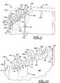
- FIG. 2shows an embodiment of a metal blank having a binder trim component with a non-linear section formed on one side;
- FIG. 3shows an embodiment of a metal blank assembly that can be used in an automotive door panel, where the metal blank assembly includes a binder trim component with a non-linear section;
- FIG. 3Ais an enlarged view of the non-linear section shown in FIG. 3 ;
- FIG. 4is a flowchart demonstrating an embodiment of a method for producing a three-dimensional metal part
- FIG. 5is a flowchart demonstrating an embodiment of a method for designing a binder trim component of a metal blank.
- the metal blank described hereinincludes a binder trim component having at least one cut edge with a non-linear section that forms a series of projections, recesses, flat sections, and other formations.
- the creation of this non-linear sectionsimultaneously forms corresponding features in a binder trim component of an adjacent metal blank so that binder material can be shared therebetween.
- the non-linear sectioncan include one or more strategically placed formations that cause it to be non-uniform along its length such that it is specifically tailored to the manufacturing requirements of the part being formed.
- metal blank 10that can be used in a wide variety of metal forming operations, such as stamping, drawing, and deep drawing, to create a three-dimensional metal part.
- metal forming operationssuch as stamping, drawing, and deep drawing
- metal blank 10is preferably made from galvanized cold-formed steel that comes in large coils, however, the composition and form of the metal blank are generally dictated by the requirements of the particular application in which it is used and could vary from those provided above.
- metal blank 10could be made from sheet metal material provided in the form of cut or blanked panels, instead of coils.
- metal blank 10is a generally planar sheet metal component and includes an outer periphery 18 having edges 20 - 26 , an inner periphery 28 having edges 30 - 36 , a binder trim component 40 formed therebetween, and a part component 42 .
- Outer periphery 18generally constitutes the outer perimeter or border of the metal blank once it has been blanked and, in this particular case, includes four edges 20 - 26 .
- Edges 20 and 22are generally elongated parallel edges that extend along the length of metal blank 10 and, according to this particular embodiment, are the manufactured sides of the coil or coil edges that are produced at the steel mill.
- Edges 34 and 36generally extend between the manufactured edges 20 and 22 and are the cut sides that are created during the operation that cuts up the coil into individual segments or metal blanks.
- the term ‘cut edge’broadly refers to any edge that is cut, sheared, blanked, trimmed, severed, or otherwise formed when the sheet metal stock is being divided into segments or blanks.
- edge 24is a cut edge, it has a complementary edge formed on the adjacent metal blank that is located to the left of metal blank 10 on the sheet metal coil, and edge 26 has a complementary edge formed on the adjacent metal blank that is located to the right of metal blank 10 on the coil.
- each of the cut edges 24 and 26includes a non-linear section that forms an alternating series of projections 50 and recesses 52 .
- both of the cut edges 24 and 26are shown here having these projections and recesses, it should be appreciated that the metal blank could be designed such that only one of the cut edges follows this non-linear path.
- the metal blankit is possible for the metal blank to include a cut edge 26 having projections and recesses and a straight cut edge 24 that extends between manufactured edges 20 and 22 (see FIG. 2 ).
- a cut edge 26having projections and recesses and a straight cut edge 24 that extends between manufactured edges 20 and 22 (see FIG. 2 ).
- any number of different edge combinationsare possible, so long as the metal blank has at least one edge of outer periphery 18 that includes a non-linear section, as taught herein.
- Projections 50 and recesses 52are generally counterparts of one another so that when a projection 50 is formed, a complementary recess 52 is formed on the adjacent metal blank.
- the width and length dimensions of the different features located along edge 26are largely determined by the particular requirements of the metal forming operation; that is, the amount of binder material needed to create adequate restraining forces to maintain the metal blank in place and to allow suitable material flow, as will be subsequently explained.
- the projectionsare shown in the form of parallelograms, however, it should be appreciated that one of a number of different configurations could be used. For instance, FIG.
- FIG. 2shows a different embodiment of metal blank 100 having a serpentine edge 102 that includes a sequence of fingerlike projections 104 and recesses 106 having a more tapered shape.
- formation of the cut edge 102causes a corresponding cut edge to be formed in the adjacent metal blank.
- Inner periphery 28(shown in dotted lines) generally corresponds to a component trim line and forms an inside perimeter of binder trim component 40 .
- the exact positioning of the inner periphery 28can be dictated by the operational requirements of the subsequent metal forming operation and, according to one embodiment, is generally determined through sophisticated computer modeled algorithms that calculate the amount of binder material that is necessary to form the desired part.
- edges 30 and 32 of the inner peripheryare shown here as linear and parallel edges, and edges 34 and 36 are shown as linear and non-parallel edges, it should be appreciated that these exemplary edges could assume various other forms, including non-linear forms, and are not limited to this specific embodiment.
- inner periphery 28is located inboard of binder trim component 40 , it is possible for some small section of the binder trim component to extend over the component trim line.
- Binder trim component 40is generally a peripheral component that extends around at least a portion of the metal blank perimeter so that during a metal forming process, upper and lower forming die can be brought together and clamp onto the different sides of the binder trim component. This clamping force around the outside of metal blank 10 prevents the blank from being pulled into the center of the die during the forming process, as is appreciated by those skilled in the art. Binder trim component 40 generally includes the material located between the outer and inner peripheries 18 and 28 and, according to this embodiment, reduces the amount of binder material along cut edges 24 and 26 .
- cut edge 26would not include any recesses; thus, the entire amount of material between the outside of cut edge 26 and inner edge 36 (dimension X; typically about 3′′) would be required as binder for this one metal blank.
- the adjoining metal blank to the rightwould also require a similar amount of material for its binder component (another 3′′ of material, resulting in a total of about 6′′ of binder material for the two metal blanks).
- the metal blank of the present applicationhas a non-linear section that only uses projections 50 as binder material on that side of the metal blank, as recesses 52 create corresponding projections in the adjacent metal blank.
- a single strip of binder material having a thickness X(which previously would have only been enough binder material for one metal blank) now serves as shared binder material for two adjoining metal blanks and results in a reduction in pitch.
- This improved utilization of shared binder trim component 40reduces the amount of scrap material, as the binder component is only used during the metal forming process and is cut off and discarded thereafter.
- Part component 42is located inboard of inner periphery 28 , and generally corresponds to the section of metal blank 10 that constitutes the metal part being formed. As will be understood by those skilled in the art, material from binder trim component 40 can and usually will flow to part component 42 during metal forming operations, but the majority of the material that ultimately makes up the resultant part comes from the part component.
- the part component 42 shown in the drawingsis simply provided for purposes of illustration, as the exact shape, size, features, arrangement, etc. of the part component could differ from the exemplary embodiment shown here.
- a projection 60is preferably the same size as a recess 62 ; this way, when recess 62 is formed, it results in a projection in the adjoining part that is equivalent to projection 60 .
- metal blank assembly 200which, in a subsequent manufacturing process, can be stamped, drawn, deep drawn, or otherwise formed into a three-dimensional metal part.
- metal blank assembly 200is particularly well suited for use as a two-piece front inner door panel for an automobile, as will be subsequently explained.
- automotive front door panelsare only one example of potential applications that could use a metal blank assembly such as this, as numerous other examples also exist, including rear door panels, non-automotive panels, and patchweld panels, to name but a few.
- metal blank assembly 200is a tailor-welded blank that includes a thick metal blank 210 (similar to metal blanks 10 and 100 in FIGS.
- Thick metal blank 210can be used to support the door hinges, as door hinges typically require a thicker and hence stronger material to mount to than do other components of the door panel. If this thicker material were used across the entire front inner door panel, then the panel would be considerably heavier and costlier. Thus, thin metal blank 212 is used for the remainder of the front inner door panel; that is, those sections that do not require quite the same strength as the hinge region. Metal blank assembly 200 thus results in a two-piece front inner door panel that achieves its structural objectives, yet does so with less weight, material, and cost.
- Weld seam 214can begin or end at welding point 216 , depending on the chosen welding process, and is preferably produced by laser welding, mash seam welding, or some other welding technique known to those skilled in the art.
- Metal blank assembly 200can be subsequently formed into a front inner door panel having a number of contoured features, including the exemplary pocket 230 outlined in broken lines. Even though it is envisioned that the front inner door panel will have a number of contoured features, in addition to pocket 230 , for purposes of illustration and simplicity only the pocket is shown here. Examples of contoured features that have been omitted from the front inner door panel for purposes of illustration include a cutout for the window, retention features for receiving an interior door module, and a space for housing an electric actuator, to name a few.
- male and female bead structureslocated around the perimeter of upper and lower die (not shown here) clamp down on binder trim component 240 so that an elongated bead zone 232 is formed around the periphery of part component 242 .
- One or more additional bead zones 234 and 236may be formed during this process as well.
- the addition of bead zones 234 and 236give greater process control by generally controlling the amount of material that is drawn from binder trim component 240 to part component 242 during forming.
- binder trim component 240includes a non-linear section 250 having a series of projections 246 , 248 , 252 , 260 , recesses 254 , 266 , 268 and flat sections 256 , 258 , where the inclusion and placement of these different formations is at least partially based on the desired characteristics of part component 242 .
- recesses 254 and 266could be placed along non-linear section 250 so that they are adjacent the pocket.
- recesses 254 and 266have been purposely located near pocket 230 so that material can more easily be drawn into the contours of the pocket when the three-dimensional metal part is being formed. As demonstrated in FIG.
- recesses 254 and 266are located at a specific location along non-linear section 250 so that they are generally aligned with pocket 230 along draw lines I.
- the draw linesare representative of the general direction of material flow during a subsequent metal forming process, such as a drawing process, and are not meant to precisely detail the exact flow of every metal particle. It could be that the exact and precise flow of metal particles follows a more complex path than that illustratively represented by draw lines I.
- One potential method for determining draw linesis to use forming simulation software, such as PAM-STAMP offered by ESI Group. In the example above, material around recesses 254 and 266 flows to pocket 230 , however, material could flow from other items of non-linear section 250 to pocket 230 and/or other features of part component 242 .
- projections 248 and 252could be provided so that they are connected by flat section 258 to define a larger projection area. Doing so provides the binder material needed for an additional bead zone 234 , which in turn increases the restraining surface and improves the ability to control material flow in the area.
- flat section 258is positioned along non-linear section 250 so that a draw line II extending from flat section 258 to pocket 230 passes through two different bead zones; i.e., bead zones 232 and 234 .
- non-linear section 250can include formations (e.g., recesses, projections, flat sections, etc.) that differ from each other in terms of shape and/or size and present different restraining surfaces to the upper and lower die. The different surfaces can result in different amounts of material flowing from binder trim component 240 to part component 242 during a metal forming operation, like drawing.
- formationse.g., recesses, projections, flat sections, etc.
- non-linear section 250with its customized arrangement of projections, recesses, flats and other features, enables one to manipulate material flow characteristics of a drawing or other forming process without having to retool the upper and/or lower dies, which can be a rather costly and timely endeavor. Instead, the change can be in binder trim component 240 and not the forming tools.
- Projections 246 , 248 , 252can be designed and arranged to improve the metal forming characteristics of the metal blank and address the specific needs of the three-dimensional part being formed. For example, it can be desirable for projection 252 to exhibit certain length-to-width relationships that are related to the thickness of the sheet metal from which the projections are formed. For sheet metal stock having a thickness ⁇ 1.0 mm, it can be desirable for the projections to have a length A and width B that satisfies the relationship: B ⁇ A/3 (dimension ‘A’ is the length of the projection taken along its longitudinal axis, dimension ‘B’ is the width of the projection measured at a halfway point; i.e., a point located halfway along the length A).
- the width dimensioncan be taken at any point along its length.
- the projectionsFor sheet metal stock having a thickness 1.0 mm-1.5 mm, inclusive, it can be desirable for the projections to have a length A and width B that satisfies the relationship: B ⁇ A/3.5.
- the projectionsFor sheet metal stock having a thickness >1.5 mm, it can be desirable for projections to have a length A and width B that satisfies the relationship: B ⁇ A/4.
- One reason that the above-provided relationshipsare dependent on the gauge of the sheet metal involves metal forming considerations. The thinner the sheet metal (e.g., ⁇ 1.0 mm), the easier it is for the projections to tear off during the forming process.
- the thicker gauge materiale.g., >1.5 mm
- non-linear section 250is generally robust enough to allow for thinner or skinnier projections.
- non-linear section 250is generally robust enough to allow for thinner or skinnier projections.
- non-linear section 250the location of projection 260 and recess 262 is particularly advantageous when it is used in conjunction with a metal blank assembly 200 like that shown here.
- Projection 260is located at one end of non-linear section 250 and lies adjacent weld seam 214 in order to improve the integrity of the weld.
- weld seam end point 216can constitute a vulnerable point of the weld seam and can be susceptible to splitting or otherwise losing some of its structural integrity. By locating weld seam end point 216 on projection 260 , the point is distanced from the interior sections of the front inner door panel that experience the greatest stresses during the forming process.
- any separation occurring at weld seam end point 216will be part of binder trim component 240 , which is subsequently cut off and discarded, and is not part of the final door panel. Contrast that with a scenario where a recess 262 , instead of projection 260 , is placed along weld seam 214 . If a separation from the weld seam end point were to occur, it could extend over the nearby part trim line, possibly resulting in the door panel being scrapped.
- the size and shape of projection 260can affect subsequent metal forming operations.
- the width ‘C’ of projection 260can be related to the length ‘A’ of projections 246 , 248 , 252 and preferably satisfies the relationship: C ⁇ A. If dimension C is too small, then there may not be enough surface for bead structures to contact and maintain the material in and around weld seam 214 during a metal forming operation.
- Exemplary bead zones 232 and 236are shown being located in projection 260 and can facilitate proper maintenance of the weld seam area during metal forming operations.
- projection 260connects with an adjacent recess 268 via a transition point 264 , which forms an obtuse angle ⁇ between upper and side edges of the projection.
- the obtuse angle ⁇can assist if a blanking process is used to create metal blank 210 , as it facilitates easy release of the part after it is blanked and it gives projection 260 a shape that controls material flow during a drawing process without jeopardizing the quality of weld seam 214 .
- Another advantage resulting from the placement of projection 260is the increase in binder material along weld seam 214 , which enables one or more additional bead zones 236 to be positioned in the area adjacent the weld seam. It has been observed that during forming operations, the areas along the weld seams are more susceptible to failure than other areas of metal blank assembly 200 .
- One possible explanationis that as material is being drawn into the front inner door panel, material from the thick and thin blank components 210 , 212 flows differently. Hence, material located on one side of weld seam 214 maybe pulling material located on the other side of the weld seam along with it.
- the addition of bead zone 236reduces the amount of material drawn and pulled from this area, thereby reducing the likelihood that weld seam 214 will split apart or otherwise be disrupted.
- the region along weld seam 214is not the only area to benefit from the placement of projection 260 .
- the location of recess 262which is the complement of projection 262 and is formed at the same time, can also improve the formability of metal blank assembly 200 .
- recess 262is generally located at an outer corner of metal blank assembly 200 and can prevent various types of surface distortions, including undesirable puckering. In some instances, forming corners can produce one of a variety of surface defects like puckers and wrinkles due to transverse stresses exerted at the intersection defining the corner. Locating recess 262 at an outer corner of a front inner door panel can reduce some of these stresses and can improve the formability of that part.
- the particular effect that a recess can have on formingis largely driven by factors such as the shape and other characteristics of the door panel or other part being formed, for example.
- Metal blanksoftentimes include one or more locating features 292 , 294 that are located around the outer perimeter of the work piece and help ensure that the metal work piece is properly positioned within the forming die.
- These locating featurescan be integrally formed in non-linear section 250 according to one of several different embodiments. For example, it is possible to simply use one or more of the projections 246 , 248 , 252 and recesses 254266 , 268 as locating features by providing corresponding locating features in the upper and/or lower forming die. This way, separate locating features would not need to be formed, as the components of non-linear section 250 are being used for this purpose as well. According to a different example, locating features 292 , 294 can be formed on non-linear section 250 (example not shown) by forming tabs, indentations, etc. on any combination of the projections, recesses, and flat sections.
- non-linear section 250By manipulating or controlling material flow characteristics through the design of binder trim component 240 , and more particularly non-linear section 250 , the strength of the weakest parts of the formed part can sometimes be strengthened so that a thinner gauge or lower quality material can be used. For instance, if the area surrounding pocket 230 were determined to be the weakest section of the front inner door panel after it was formed, then non-linear section 250 could be used to strengthen or thicken that pocket.
- binder trim component 240 , non-linear section 250 , and the various features of the non-linear sectioncould be incorporated into one or more edges of metal blank 210 and/or metal blank 212 , or they could be used with a monolithic blank (i.e., a single blank that is not welded to another blank before a metal forming operation). In one embodiment, all of the outer peripheral edges of metal blank assembly 200 have some type of customized non-linear section extending thereon.
- FIG. 4there is shown a flowchart demonstrating some of the primary steps of an embodiment 300 of a method for forming a three-dimensional metal structure.
- a sheet metal coilis received and processed by treating, washing and/or slitting the coil, wiping the coil of materials such as oil, and performing any other prerequisite processing steps known to those skilled in the art, step 302 .
- the sheet metal coilOnce the sheet metal coil has been properly processed, it is sent through a blanking operation, step 304 , in which a plurality of metal blanks each having an outer periphery similar to the ones shown in FIGS. 1 and 2 are created.
- each of the individual metal blanksare then laser or otherwise welded to a sheet metal piece of a different thickness or grade so that a tailor-welded blank assembly is created, step 306 .
- the metal blank assembly(be it a tailor- or non-tailor-welded blank assembly) is put through a metal forming operation, step 308 , that forms the various contours of the desired part.
- the metal blankis interposed between upper and lower die and is clamped along an outer section which is the binder trim component.
- One of the two dieincludes a male component or bead that extends around an outer perimeter of the die and mates with a complementary female component or groove of the other die so that the binder trim component, including the various projections, is trapped therebetween. This creates proper restraining forces on top and bottom sides of the metal blank assembly that prevents it from being drawn into the die cavity too freely (which can cause wrinkles) or too restrictively (which can cause the metal blank to tear or split) during the stamping operation.
- One of a number of different bead structurescould be used, including square, trapezoidal, semi-circular, or other known configurations.
- the partis released and the binder trim component is removed, step 310 .
- the actual method used for removing the binder trim componentcan vary, but could include techniques such as laser cutting, water jet, die cutting, etc. It should of course be understood that the foregoing description of method steps is simply meant to be an exemplary illustration of some of the primary steps used in such an operation and that many changes to the process could be made. For example, specific deep drawing, stretch forming, press forming, as well as other stamping techniques, for example, could be used.
- FIG. 5there is shown an embodiment 400 of a method for designing a binder trim component for a metal blank, where the metal blank is used in a subsequent metal forming operation to make a proposed part.
- the methodperforms a forming simulation that analyzes a metal forming operation on the proposed part.
- the forming simulationis a computer-based forming simulation that uses non-linear finite element analysis to simulate the metal forming operation and predict common defects such as splits, tears, wrinkles, puckers, springback, material thinning, and the like, as well as the draw-in distances of various sections.
- the forming simulationis a physical-based forming simulation, such as a circle-grid analysis, that analyzes material flow by using observing draw-in distances and the like.
- step 402preferably identifies one or more sections of the binder trim component where significant material flow is likely to occur; these sections are referred to as ‘target forming sections’ and can be determined by, inter alia, their respective draw-in distance. In one embodiment, step 402 even identifies the section or side of the proposed binder trim component where the most draw-in distance is likely to occur.
- step 404performs a nesting simulation that analyzes different arrangements of the proposed part on the sheet metal stock (e.g., coil, flat panels, etc.) in order to determine how to most efficiently arrange the proposed part so that it reduces the amount of wasted material.
- the nesting simulationis performed by one of a variety of types of computer-based nesting simulation software.
- This type of computer-based nesting simulation softwarecan include versions that: allow for flipping, rotating, or otherwise manipulating the sheet metal stock, take into account the limitations of the shearing, cutting or punching tools involved, and can identify defects on the sheet metal stock, to name but a few potential options.
- One suitable program for performing such a simulationis BlankNest sold by Javelin Technologies; however, other programs could certainly be used instead.
- step 404it can be desirable for step 404 to identify one or more sections of the binder trim component where binder trim material can be saved through the use of non-linear sections, such as those previously described. These sections are hereafter referred to as ‘target nesting sections’. If no target nesting sections are identified, it may be necessary to re-perform the nesting simulation so that the proposed parts are rotated or arranged differently on the sheet metal stock.
- Step 406then utilizes the target forming and target nesting sections identified above to determine an optimum binder trim location for a non-linear section, such as non-linear section 250 .
- the placement of the optimum binder trim locationis mindful of both metal forming considerations (i.e., target forming sections) and scrap metal reduction considerations (i.e., target nesting sections).
- method 400determines the best location around the binder trim component for a non-linear section based on metal forming considerations, determines the best location around the binder trim component for a non-linear section based on scrap metal reduction considerations, and then looks for a common location that addresses or satisfies both concerns; this common or overlapped location corresponds to the optimum binder trim location.
- step 406can consider all of the factors and make a decision based on the totality of the circumstances, including metal forming considerations, scrap metal saving considerations, and others.
- step 408develops a non-linear section having a combination of projections, recesses, flat sections, and other formations that are specifically designed for the optimum binder trim location and the proposed part.
- formations like recessescan be added to the non-linear section near pockets, embossments, flat sections, and other part features to promote material flow in the area; formations like projections can be added to restrict material flow by providing binder material for the upper and lower die to clamp down on; and formations such as flat sections can be inserted along the non-linear section to accommodate draw beads, lock beads, and other types of features that even further limit material flow during drawing operations and the like.
- the precise placement, size, shape, number, etc. of these formationsis largely driven by factors such as the requirements of the proposed part and the optimum binder trim location.
- the terms “for example”, “for instance”, “like”, and “such as,” and the verbs “comprising,” “having,” “including,” and their other verb forms, when used in conjunction with a listing of one or more components or other items,are each to be construed as open-ended, meaning that that the listing is not to be considered as excluding other, additional components or items.
- Other termsare to be construed using their broadest reasonable meaning unless they are used in a context that requires a different interpretation.
Landscapes
- Engineering & Computer Science (AREA)
- Mechanical Engineering (AREA)
- Shaping Metal By Deep-Drawing, Or The Like (AREA)
- Laminated Bodies (AREA)
Abstract
Description
Claims (15)
Priority Applications (2)
| Application Number | Priority Date | Filing Date | Title |
|---|---|---|---|
| US12/039,266US8062763B2 (en) | 2007-02-28 | 2008-02-28 | Metal blank with binder trim component |
| US13/274,983US8573021B2 (en) | 2007-02-28 | 2011-10-17 | Metal blank with binder trim component and method |
Applications Claiming Priority (2)
| Application Number | Priority Date | Filing Date | Title |
|---|---|---|---|
| US90399807P | 2007-02-28 | 2007-02-28 | |
| US12/039,266US8062763B2 (en) | 2007-02-28 | 2008-02-28 | Metal blank with binder trim component |
Related Child Applications (1)
| Application Number | Title | Priority Date | Filing Date |
|---|---|---|---|
| US13/274,983DivisionUS8573021B2 (en) | 2007-02-28 | 2011-10-17 | Metal blank with binder trim component and method |
Publications (2)
| Publication Number | Publication Date |
|---|---|
| US20080209974A1 US20080209974A1 (en) | 2008-09-04 |
| US8062763B2true US8062763B2 (en) | 2011-11-22 |
Family
ID=39721611
Family Applications (2)
| Application Number | Title | Priority Date | Filing Date |
|---|---|---|---|
| US12/039,266Active2030-05-02US8062763B2 (en) | 2007-02-28 | 2008-02-28 | Metal blank with binder trim component |
| US13/274,983ActiveUS8573021B2 (en) | 2007-02-28 | 2011-10-17 | Metal blank with binder trim component and method |
Family Applications After (1)
| Application Number | Title | Priority Date | Filing Date |
|---|---|---|---|
| US13/274,983ActiveUS8573021B2 (en) | 2007-02-28 | 2011-10-17 | Metal blank with binder trim component and method |
Country Status (6)
| Country | Link |
|---|---|
| US (2) | US8062763B2 (en) |
| JP (1) | JP5298032B2 (en) |
| KR (1) | KR101466660B1 (en) |
| CN (1) | CN101641168B (en) |
| DE (1) | DE112008000488T5 (en) |
| WO (1) | WO2008106591A1 (en) |
Cited By (2)
| Publication number | Priority date | Publication date | Assignee | Title |
|---|---|---|---|---|
| US20110304727A1 (en)* | 2010-06-11 | 2011-12-15 | Pilkington Group Limited | Apparatus for evaluating fit of a modular assembly into a body opening and method of using same |
| USD854142S1 (en)* | 2017-07-26 | 2019-07-16 | Ascent Products, Llc | Ventilation fan housing |
Families Citing this family (19)
| Publication number | Priority date | Publication date | Assignee | Title |
|---|---|---|---|---|
| WO2010006278A2 (en)* | 2008-07-10 | 2010-01-14 | Shiloh Industries, Inc. | Metal forming process and welded coil assembly |
| CA2695101C (en) | 2010-03-01 | 2012-10-16 | Honda Motor Co., Ltd. | Reducing waste in metal stamping processes and systems therefor |
| US9402698B2 (en)* | 2010-11-03 | 2016-08-02 | Global Dental Service LLC | Systems and processes for forming anatomical features in dentures |
| US20150037760A1 (en) | 2010-11-03 | 2015-02-05 | Timothy C. Thompson | System and Process for Duplication of Dentures |
| US9213784B2 (en) | 2010-11-03 | 2015-12-15 | Global Dental Science Llc | System and process for optimization of dentures |
| US9155599B2 (en) | 2010-11-03 | 2015-10-13 | Global Dental Science Llc | Systems and processes for forming anatomical features in dentures |
| US8875398B2 (en) | 2012-01-04 | 2014-11-04 | Thomas J. Balshi | Dental prosthesis and method of its production utilizing standardized framework keys and matching premanufactured teeth |
| US9364302B2 (en) | 2012-02-08 | 2016-06-14 | Global Dental Science Llc | Process and systems for molding thermosetting plastics |
| CN103286187B (en)* | 2012-02-22 | 2015-11-18 | 上海微电子装备有限公司 | A kind of method of sheet material blanking and typesetting and device |
| WO2014130536A1 (en) | 2013-02-19 | 2014-08-28 | Global Dental Science Llc | Removable system and method for dentures and surgical guides |
| US9867684B2 (en) | 2013-03-14 | 2018-01-16 | Global Dental Sciences LLC | System and process for manufacturing of dentures |
| US9055993B2 (en) | 2013-08-29 | 2015-06-16 | Global Dental Science Llc | Denture reference and registration system |
| US10251733B2 (en) | 2014-03-03 | 2019-04-09 | Global Dental Science Llc | System and method for manufacturing layered dentures |
| US10206764B2 (en) | 2014-03-03 | 2019-02-19 | Global Dental Sciences, LLC | System and method for manufacturing layered dentures |
| GB2548231A (en)* | 2014-09-12 | 2017-09-13 | Honda Motor Co Ltd | Press forming method and plate material expansion device used in said method |
| US10579039B2 (en)* | 2015-01-15 | 2020-03-03 | Livermore Software Technology Corporation | Setting up physical tools for scrap trimming operations in sheet metal forming based on numerical simulation results |
| US20160210385A1 (en)* | 2015-01-15 | 2016-07-21 | Livermore Software Technology Corporation | Numerical Simulation of Scrap Trimming Operations in Sheet Metal Forming |
| US11648084B2 (en) | 2015-06-11 | 2023-05-16 | Global Dental Science Llc | Positioning method and system for implant-supported dentures |
| US11266486B2 (en) | 2016-06-20 | 2022-03-08 | Global Dental Science, LLC | Positioning handle and occlusal locks for removable prosthesis |
Citations (43)
| Publication number | Priority date | Publication date | Assignee | Title |
|---|---|---|---|---|
| US1167556A (en) | 1914-06-11 | 1916-01-11 | Briscoe Mfg Company | Method of forming sheet metal. |
| US1800531A (en) | 1929-02-13 | 1931-04-14 | American Can Co | Method of producing one-piece drawn containers |
| US1898883A (en) | 1930-07-26 | 1933-02-21 | Company Union Guardian Trust | Method of stamping front one-piece automobile fenders |
| US1900004A (en)* | 1927-12-15 | 1933-03-07 | Bendix Brake Co | Method of forming brake shoes and blanks therefor |
| US1962279A (en) | 1933-04-20 | 1934-06-12 | Howard R Lott | Process of making flatware |
| US2177970A (en)* | 1938-04-11 | 1939-10-31 | William L Wettlaufer | Golf club shaft |
| US2335292A (en) | 1942-04-03 | 1943-11-30 | Robert W Messenger | Sheet and method of producing same for the economical production of blanks |
| US2387767A (en) | 1944-06-19 | 1945-10-30 | American Can Co | Sheet cutting machine |
| US2400590A (en)* | 1944-05-18 | 1946-05-21 | E A Lab Inc | Method of making commutators |
| US2850202A (en)* | 1956-03-14 | 1958-09-02 | Appleton Electric Co | Outlet box and method of manufacture of the same |
| US2963783A (en)* | 1957-07-31 | 1960-12-13 | Williamson Company | Sheet metal fittings |
| US3008441A (en)* | 1957-07-16 | 1961-11-14 | Lisle W Menzimer | Method of making door support housings |
| US3262361A (en) | 1964-06-02 | 1966-07-26 | Pacifico T Alfonsi | Photographic enlarging easel and mask |
| US3299689A (en) | 1964-05-18 | 1967-01-24 | Cyril Bath Co | Method and apparatus for combined stretch forming and die drawing |
| US3339333A (en) | 1965-04-05 | 1967-09-05 | Metcom Products Co | Back-up tab for siding |
| US4106422A (en) | 1977-03-14 | 1978-08-15 | Buhrke Industries, Inc. | Method for manufacture of can end closures |
| US4119050A (en) | 1977-01-10 | 1978-10-10 | Klein Gerald B | Method for the manufacture of a can lid having a triple-fold, pushdown gate |
| US4210041A (en) | 1979-02-08 | 1980-07-01 | Enrique Mitman | Method for cutting a plurality of identical, irregular, non-polygonal pieces from material with minimum waste |
| JPS55103061A (en) | 1979-02-02 | 1980-08-06 | Hitachi Ltd | Blanking method of sector steel plate for rotary electric machine |
| US4244315A (en) | 1978-07-24 | 1981-01-13 | Klein Gerald B | Method for the manufacture of a can lid having a triple-fold pushdown gate |
| SU1090473A1 (en) | 1982-09-15 | 1984-05-07 | Всесоюзный Ордена Трудового Красного Знамени Заочный Политехнический Институт | Sheet blank for drawing |
| US4603571A (en) | 1984-08-07 | 1986-08-05 | Wessels Ewald J H | Apparatus for drawing circular cups from non-circular blanks |
| US5128877A (en) | 1990-06-08 | 1992-07-07 | Ford Motor Company | Method of draw forming analytically determined binder wrap blank shape |
| JPH0631353A (en) | 1992-07-16 | 1994-02-08 | Mitsui High Tec Inc | Manufacture of laminated iron core |
| US5372027A (en) | 1989-11-29 | 1994-12-13 | Armco Steel Company, L.P. | Controlled material flow hydroforming |
| US5379227A (en) | 1992-12-21 | 1995-01-03 | Ford Motor Company | Method for aiding sheet metal forming tooling design |
| US5390127A (en) | 1992-12-21 | 1995-02-14 | Ford Motor Company | Method and apparatus for predicting post-buckling deformation of sheet metal |
| US5426337A (en)* | 1990-08-31 | 1995-06-20 | Jidosha Denki Kogyo Kabushiki Kaisha | Sheet metal casing for a small electric motor |
| US5463558A (en) | 1994-02-04 | 1995-10-31 | Ford Motor Company | Method for designing a binder ring surface for a sheet metal part |
| US5572896A (en) | 1994-02-25 | 1996-11-12 | Aluminum Company Of America | Strain path control in forming processes |
| US5600991A (en) | 1995-02-10 | 1997-02-11 | Ogihara America Corporation | Stretch controlled forming mechanism and method for forming multiple gauge welded blanks |
| US5604044A (en) | 1992-12-28 | 1997-02-18 | Mccabe; Charles J. | Blanks for sheet material forming process |
| US5630337A (en) | 1995-09-07 | 1997-05-20 | Werth; Elmer D. | Apparatus and method for forming a container |
| US5901599A (en) | 1995-07-18 | 1999-05-11 | Toyota Jidosha Kabushiki Kaisha | Method and apparatus for sheet forming a blank using a variable bead |
| US6408516B1 (en) | 1999-08-27 | 2002-06-25 | Shiloh Industries, Inc. Dickson Mfg. Div. | Sunroof opening for vehicle roof panel |
| DE10120880A1 (en) | 2001-04-27 | 2002-10-31 | Audi Ag | Deep drawn component manufacturing process involves positioning cutouts so that they at least partly extend into grooves formed in plate between bead recesses and beads |
| US6513860B1 (en)* | 2000-04-26 | 2003-02-04 | Ford Global Technologies, Inc. | Method and apparatus for forming a three piece tailor welded door blank |
| US6588248B1 (en) | 1999-02-23 | 2003-07-08 | Ks Gleitlager Gmbh | Wrapped plain bearing bush |
| JP2004160490A (en) | 2002-11-13 | 2004-06-10 | Nissan Motor Co Ltd | Blank material and press molding method using the blank material |
| US6903475B2 (en)* | 2001-02-23 | 2005-06-07 | Black & Decker Inc. | Stator assembly with an overmolding that secures magnets to a flux ring and the flux ring to a stator housing |
| US20050183487A1 (en) | 2004-02-20 | 2005-08-25 | Saab Automobile Ab | Sheet metal section |
| US20050200164A1 (en)* | 2004-03-12 | 2005-09-15 | Ford Global Technologies Llc | Automotive vehicle body having tailor welded blanks |
| US7448178B2 (en)* | 2004-09-14 | 2008-11-11 | Michael Joseph Visone | Field fabricated joist hanger |
Family Cites Families (12)
| Publication number | Priority date | Publication date | Assignee | Title |
|---|---|---|---|---|
| US3543559A (en)* | 1968-12-23 | 1970-12-01 | Continental Can Co | Cup blanking and forming method and tooling therefor |
| JPS5528339Y2 (en)* | 1976-06-08 | 1980-07-07 | ||
| JPH1157877A (en)* | 1997-08-08 | 1999-03-02 | Honda Motor Co Ltd | Press molding method |
| JPH11242707A (en)* | 1998-02-25 | 1999-09-07 | Amada Co Ltd | Method and apparatus for reusing remaining material after sheet processing |
| JP4627937B2 (en)* | 2001-09-06 | 2011-02-09 | 本田技研工業株式会社 | Method and apparatus for press forming aggregate blank material |
| CN1121285C (en)* | 2001-10-09 | 2003-09-17 | 湖南大学 | Drawing die for forming metallic sheet by punching |
| CN2510195Y (en)* | 2001-10-09 | 2002-09-11 | 湖南大学 | Drawing die for stamping metal thin plate |
| JP3979492B2 (en)* | 2002-07-22 | 2007-09-19 | 新日本製鐵株式会社 | Molding analysis method of press parts by computer simulation and characteristic analysis method of structures including press parts |
| US7130708B2 (en)* | 2003-04-01 | 2006-10-31 | General Motors Corporation | Draw-in map for stamping die tryout |
| JP4524573B2 (en)* | 2004-03-31 | 2010-08-18 | マツダ株式会社 | Press molded product shape prediction method, prediction program, recording medium recording the program, and press molding method |
| US7200496B2 (en)* | 2005-06-02 | 2007-04-03 | Ford Global Technologies, Llc | Method of predicting wear of a die surface |
| JP4769501B2 (en)* | 2005-07-12 | 2011-09-07 | 東プレ株式会社 | Deep drawing method |
- 2008
- 2008-02-28DEDE112008000488Tpatent/DE112008000488T5/ennot_activeWithdrawn
- 2008-02-28JPJP2009551846Apatent/JP5298032B2/ennot_activeExpired - Fee Related
- 2008-02-28KRKR1020097020223Apatent/KR101466660B1/ennot_activeExpired - Fee Related
- 2008-02-28USUS12/039,266patent/US8062763B2/enactiveActive
- 2008-02-28WOPCT/US2008/055279patent/WO2008106591A1/enactiveApplication Filing
- 2008-02-28CNCN2008800063376Apatent/CN101641168B/ennot_activeExpired - Fee Related
- 2011
- 2011-10-17USUS13/274,983patent/US8573021B2/enactiveActive
Patent Citations (44)
| Publication number | Priority date | Publication date | Assignee | Title |
|---|---|---|---|---|
| US1167556A (en) | 1914-06-11 | 1916-01-11 | Briscoe Mfg Company | Method of forming sheet metal. |
| US1900004A (en)* | 1927-12-15 | 1933-03-07 | Bendix Brake Co | Method of forming brake shoes and blanks therefor |
| US1800531A (en) | 1929-02-13 | 1931-04-14 | American Can Co | Method of producing one-piece drawn containers |
| US1898883A (en) | 1930-07-26 | 1933-02-21 | Company Union Guardian Trust | Method of stamping front one-piece automobile fenders |
| US1962279A (en) | 1933-04-20 | 1934-06-12 | Howard R Lott | Process of making flatware |
| US2177970A (en)* | 1938-04-11 | 1939-10-31 | William L Wettlaufer | Golf club shaft |
| US2335292A (en) | 1942-04-03 | 1943-11-30 | Robert W Messenger | Sheet and method of producing same for the economical production of blanks |
| US2400590A (en)* | 1944-05-18 | 1946-05-21 | E A Lab Inc | Method of making commutators |
| US2387767A (en) | 1944-06-19 | 1945-10-30 | American Can Co | Sheet cutting machine |
| US2850202A (en)* | 1956-03-14 | 1958-09-02 | Appleton Electric Co | Outlet box and method of manufacture of the same |
| US3008441A (en)* | 1957-07-16 | 1961-11-14 | Lisle W Menzimer | Method of making door support housings |
| US2963783A (en)* | 1957-07-31 | 1960-12-13 | Williamson Company | Sheet metal fittings |
| US3299689A (en) | 1964-05-18 | 1967-01-24 | Cyril Bath Co | Method and apparatus for combined stretch forming and die drawing |
| US3262361A (en) | 1964-06-02 | 1966-07-26 | Pacifico T Alfonsi | Photographic enlarging easel and mask |
| US3339333A (en) | 1965-04-05 | 1967-09-05 | Metcom Products Co | Back-up tab for siding |
| US4119050A (en) | 1977-01-10 | 1978-10-10 | Klein Gerald B | Method for the manufacture of a can lid having a triple-fold, pushdown gate |
| US4106422A (en) | 1977-03-14 | 1978-08-15 | Buhrke Industries, Inc. | Method for manufacture of can end closures |
| US4244315A (en) | 1978-07-24 | 1981-01-13 | Klein Gerald B | Method for the manufacture of a can lid having a triple-fold pushdown gate |
| JPS55103061A (en) | 1979-02-02 | 1980-08-06 | Hitachi Ltd | Blanking method of sector steel plate for rotary electric machine |
| US4210041A (en) | 1979-02-08 | 1980-07-01 | Enrique Mitman | Method for cutting a plurality of identical, irregular, non-polygonal pieces from material with minimum waste |
| SU1090473A1 (en) | 1982-09-15 | 1984-05-07 | Всесоюзный Ордена Трудового Красного Знамени Заочный Политехнический Институт | Sheet blank for drawing |
| US4603571A (en) | 1984-08-07 | 1986-08-05 | Wessels Ewald J H | Apparatus for drawing circular cups from non-circular blanks |
| US5372027A (en) | 1989-11-29 | 1994-12-13 | Armco Steel Company, L.P. | Controlled material flow hydroforming |
| US5128877A (en) | 1990-06-08 | 1992-07-07 | Ford Motor Company | Method of draw forming analytically determined binder wrap blank shape |
| US5426337A (en)* | 1990-08-31 | 1995-06-20 | Jidosha Denki Kogyo Kabushiki Kaisha | Sheet metal casing for a small electric motor |
| JPH0631353A (en) | 1992-07-16 | 1994-02-08 | Mitsui High Tec Inc | Manufacture of laminated iron core |
| US5379227A (en) | 1992-12-21 | 1995-01-03 | Ford Motor Company | Method for aiding sheet metal forming tooling design |
| US5390127A (en) | 1992-12-21 | 1995-02-14 | Ford Motor Company | Method and apparatus for predicting post-buckling deformation of sheet metal |
| US5604044A (en) | 1992-12-28 | 1997-02-18 | Mccabe; Charles J. | Blanks for sheet material forming process |
| US5463558A (en) | 1994-02-04 | 1995-10-31 | Ford Motor Company | Method for designing a binder ring surface for a sheet metal part |
| US5572896A (en) | 1994-02-25 | 1996-11-12 | Aluminum Company Of America | Strain path control in forming processes |
| US5600991A (en) | 1995-02-10 | 1997-02-11 | Ogihara America Corporation | Stretch controlled forming mechanism and method for forming multiple gauge welded blanks |
| US5901599A (en) | 1995-07-18 | 1999-05-11 | Toyota Jidosha Kabushiki Kaisha | Method and apparatus for sheet forming a blank using a variable bead |
| US5749258A (en) | 1995-09-07 | 1998-05-12 | Werth; Elmer D. | Tooling and method for forming a container |
| US5630337A (en) | 1995-09-07 | 1997-05-20 | Werth; Elmer D. | Apparatus and method for forming a container |
| US6588248B1 (en) | 1999-02-23 | 2003-07-08 | Ks Gleitlager Gmbh | Wrapped plain bearing bush |
| US6408516B1 (en) | 1999-08-27 | 2002-06-25 | Shiloh Industries, Inc. Dickson Mfg. Div. | Sunroof opening for vehicle roof panel |
| US6513860B1 (en)* | 2000-04-26 | 2003-02-04 | Ford Global Technologies, Inc. | Method and apparatus for forming a three piece tailor welded door blank |
| US6903475B2 (en)* | 2001-02-23 | 2005-06-07 | Black & Decker Inc. | Stator assembly with an overmolding that secures magnets to a flux ring and the flux ring to a stator housing |
| DE10120880A1 (en) | 2001-04-27 | 2002-10-31 | Audi Ag | Deep drawn component manufacturing process involves positioning cutouts so that they at least partly extend into grooves formed in plate between bead recesses and beads |
| JP2004160490A (en) | 2002-11-13 | 2004-06-10 | Nissan Motor Co Ltd | Blank material and press molding method using the blank material |
| US20050183487A1 (en) | 2004-02-20 | 2005-08-25 | Saab Automobile Ab | Sheet metal section |
| US20050200164A1 (en)* | 2004-03-12 | 2005-09-15 | Ford Global Technologies Llc | Automotive vehicle body having tailor welded blanks |
| US7448178B2 (en)* | 2004-09-14 | 2008-11-11 | Michael Joseph Visone | Field fabricated joist hanger |
Non-Patent Citations (2)
| Title |
|---|
| English machine translation of JP 2004-160490. Jun. 2004.* |
| Written Opinion & International Search Report for PCT/US08/55279, Jul. 25, 2008, 6 pages. |
Cited By (3)
| Publication number | Priority date | Publication date | Assignee | Title |
|---|---|---|---|---|
| US20110304727A1 (en)* | 2010-06-11 | 2011-12-15 | Pilkington Group Limited | Apparatus for evaluating fit of a modular assembly into a body opening and method of using same |
| US8723950B2 (en)* | 2010-06-11 | 2014-05-13 | Pilkington Group Limited | Apparatus for evaluating fit of a modular assembly into a body opening and method of using same |
| USD854142S1 (en)* | 2017-07-26 | 2019-07-16 | Ascent Products, Llc | Ventilation fan housing |
Also Published As
| Publication number | Publication date |
|---|---|
| CN101641168A (en) | 2010-02-03 |
| CN101641168B (en) | 2011-07-13 |
| US20080209974A1 (en) | 2008-09-04 |
| JP2010520059A (en) | 2010-06-10 |
| DE112008000488T5 (en) | 2010-02-11 |
| US8573021B2 (en) | 2013-11-05 |
| JP5298032B2 (en) | 2013-09-25 |
| US20120035902A1 (en) | 2012-02-09 |
| KR20090115972A (en) | 2009-11-10 |
| KR101466660B1 (en) | 2014-11-28 |
| WO2008106591A1 (en) | 2008-09-04 |
Similar Documents
| Publication | Publication Date | Title |
|---|---|---|
| US8062763B2 (en) | Metal blank with binder trim component | |
| US8545157B2 (en) | Metal members and assemblies that have reinforced punched holes and method of forming the holes | |
| EP1186516B1 (en) | Tailored blank product and method of manufacturing the product | |
| US7748743B2 (en) | Structural or chassis component for a motor vehicle, and method of making such a structural or chassis component | |
| EP2939754B1 (en) | Draw forming method | |
| WO2016117226A1 (en) | Forged rivet for joining dissimilar materials, dissimilar material-joining method, and product of joined dissimilar materials | |
| US20190291160A1 (en) | Method for machining a sheet-metal profile | |
| KR101230592B1 (en) | One piece type trailing arm and its manufacturing method | |
| US20150314363A1 (en) | Method of forming a vehicle body structure from a pre-welded blank assembly | |
| CN102756034B (en) | Manufacturing method of side panel | |
| JP2012148332A (en) | Method of manufacturing tailored blank material | |
| US8887397B2 (en) | Door inner panel for automobile and method of manufacturing same | |
| JP6104427B2 (en) | Dissimilar material joint | |
| US11458526B2 (en) | Method of machining an opening in a plurality of blanks | |
| JP2015016486A (en) | Thickness difference plate and production method thereof | |
| JP2005279684A (en) | Welded metal pipe with flange and method for manufacturing the same | |
| JP6426043B2 (en) | Rivet for dissimilar material joining, dissimilar material joined body, and dissimilar material joining method | |
| US20060231534A1 (en) | Method of laser welding coated members | |
| CN110480270B (en) | Machining process of mounting bracket | |
| US1860683A (en) | Method of making metal stampings | |
| JP2005118796A (en) | Butt welding method | |
| KR101983973B1 (en) | method for manufacturing vehicle's hood striker | |
| JPH0360873A (en) | Seam welding method | |
| CN117600771A (en) | Manufacturing method and automobile part | |
| WO2020022984A2 (en) | Method for reducing scrap costs during processing of sheet metal materials |
Legal Events
| Date | Code | Title | Description |
|---|---|---|---|
| AS | Assignment | Owner name:SHILOH INDUSTRIES, INC., OHIO Free format text:ASSIGNMENT OF ASSIGNORS INTEREST;ASSIGNORS:EWOLSKI, JOHN R.;WALTHER, JAMES W.;FETSKO, STEPHEN A.;REEL/FRAME:020581/0618 Effective date:20080228 | |
| STCF | Information on status: patent grant | Free format text:PATENTED CASE | |
| AS | Assignment | Owner name:BANK OF AMERICA, N.A., AS ADMINISTRATIVE AGENT, IL Free format text:NOTICE OF GRANT OF SECURITY INTEREST IN PATENTS;ASSIGNOR:SHILOH INDUSTRIES, INC.;REEL/FRAME:031515/0558 Effective date:20131025 | |
| FPAY | Fee payment | Year of fee payment:4 | |
| AS | Assignment | Owner name:BANK OF AMERICA, N.A., AS ADMINISTRATIVE AGENT, OH Free format text:NOTICE OF GRANT OF SECURITY INTEREST IN PATENTS;ASSIGNOR:SHILOH INDUSTRIES, INC.;REEL/FRAME:037236/0943 Effective date:20131025 | |
| MAFP | Maintenance fee payment | Free format text:PAYMENT OF MAINTENANCE FEE, 8TH YEAR, LARGE ENTITY (ORIGINAL EVENT CODE: M1552); ENTITY STATUS OF PATENT OWNER: LARGE ENTITY Year of fee payment:8 | |
| AS | Assignment | Owner name:CERBERUS BUSINESS FINANCE AGENCY, LLC, AS COLLATERAL AGENT, NEW YORK Free format text:ASSIGNMENT OF SECURITY INTEREST - PATENTS;ASSIGNORS:GROUPER BLANKING, LLC;GROUPER STAMPING, LLC;GROUPER CASTING, LLC;REEL/FRAME:054557/0982 Effective date:20201130 | |
| AS | Assignment | Owner name:GROUPER BLANKING, LLC, KENTUCKY Free format text:ASSIGNMENT OF ASSIGNORS INTEREST;ASSIGNOR:SHILOH INDUSTRIES, INC.;REEL/FRAME:054832/0195 Effective date:20201130 | |
| AS | Assignment | Owner name:SHILOH INDUSTRIES, INC., OHIO Free format text:RELEASE BY SECURED PARTY;ASSIGNOR:BANK OF AMERICA, N.A., AS ADMINISTRATIVE AGENT;REEL/FRAME:055019/0964 Effective date:20201130 | |
| AS | Assignment | Owner name:GROUPER CASTING, LLC, OHIO Free format text:RELEASE OF SECURITY INTEREST IN PATENTS;ASSIGNOR:CERBERUS BUSINESS FINANCE AGENCY, LLC;REEL/FRAME:055953/0389 Effective date:20210412 Owner name:GROUPER BLANKING, LLC, OHIO Free format text:RELEASE OF SECURITY INTEREST IN PATENTS;ASSIGNOR:CERBERUS BUSINESS FINANCE AGENCY, LLC;REEL/FRAME:055953/0389 Effective date:20210412 Owner name:GROUPER STAMPING, LLC, OHIO Free format text:RELEASE OF SECURITY INTEREST IN PATENTS;ASSIGNOR:CERBERUS BUSINESS FINANCE AGENCY, LLC;REEL/FRAME:055953/0389 Effective date:20210412 | |
| AS | Assignment | Owner name:TWB COMPANY, LLC, MICHIGAN Free format text:ASSIGNMENT OF ASSIGNORS INTEREST;ASSIGNOR:GROUPER BLANKING, LLC;REEL/FRAME:058111/0366 Effective date:20210608 | |
| MAFP | Maintenance fee payment | Free format text:PAYMENT OF MAINTENANCE FEE, 12TH YEAR, LARGE ENTITY (ORIGINAL EVENT CODE: M1553); ENTITY STATUS OF PATENT OWNER: LARGE ENTITY Year of fee payment:12 |