US8062453B2 - Method for quasi-instantaneous polymerization of filament wound composite materials - Google Patents
Method for quasi-instantaneous polymerization of filament wound composite materialsDownload PDFInfo
- Publication number
- US8062453B2 US8062453B2US12/415,462US41546209AUS8062453B2US 8062453 B2US8062453 B2US 8062453B2US 41546209 AUS41546209 AUS 41546209AUS 8062453 B2US8062453 B2US 8062453B2
- Authority
- US
- United States
- Prior art keywords
- fibers
- mandrel
- ultra
- tension
- resin matrix
- Prior art date
- Legal status (The legal status is an assumption and is not a legal conclusion. Google has not performed a legal analysis and makes no representation as to the accuracy of the status listed.)
- Expired - Fee Related, expires
Links
Images


Classifications
- B—PERFORMING OPERATIONS; TRANSPORTING
- B29—WORKING OF PLASTICS; WORKING OF SUBSTANCES IN A PLASTIC STATE IN GENERAL
- B29C—SHAPING OR JOINING OF PLASTICS; SHAPING OF MATERIAL IN A PLASTIC STATE, NOT OTHERWISE PROVIDED FOR; AFTER-TREATMENT OF THE SHAPED PRODUCTS, e.g. REPAIRING
- B29C53/00—Shaping by bending, folding, twisting, straightening or flattening; Apparatus therefor
- B29C53/80—Component parts, details or accessories; Auxiliary operations
- B29C53/8008—Component parts, details or accessories; Auxiliary operations specially adapted for winding and joining
- F—MECHANICAL ENGINEERING; LIGHTING; HEATING; WEAPONS; BLASTING
- F41—WEAPONS
- F41A—FUNCTIONAL FEATURES OR DETAILS COMMON TO BOTH SMALLARMS AND ORDNANCE, e.g. CANNONS; MOUNTINGS FOR SMALLARMS OR ORDNANCE
- F41A21/00—Barrels; Gun tubes; Muzzle attachments; Barrel mounting means
- F41A21/20—Barrels or gun tubes characterised by the material
- F—MECHANICAL ENGINEERING; LIGHTING; HEATING; WEAPONS; BLASTING
- F41—WEAPONS
- F41B—WEAPONS FOR PROJECTING MISSILES WITHOUT USE OF EXPLOSIVE OR COMBUSTIBLE PROPELLANT CHARGE; WEAPONS NOT OTHERWISE PROVIDED FOR
- F41B6/00—Electromagnetic launchers ; Plasma-actuated launchers
- F41B6/006—Rail launchers
- B—PERFORMING OPERATIONS; TRANSPORTING
- B29—WORKING OF PLASTICS; WORKING OF SUBSTANCES IN A PLASTIC STATE IN GENERAL
- B29C—SHAPING OR JOINING OF PLASTICS; SHAPING OF MATERIAL IN A PLASTIC STATE, NOT OTHERWISE PROVIDED FOR; AFTER-TREATMENT OF THE SHAPED PRODUCTS, e.g. REPAIRING
- B29C35/00—Heating, cooling or curing, e.g. crosslinking or vulcanising; Apparatus therefor
- B29C35/02—Heating or curing, e.g. crosslinking or vulcanizing during moulding, e.g. in a mould
- B29C35/08—Heating or curing, e.g. crosslinking or vulcanizing during moulding, e.g. in a mould by wave energy or particle radiation
- B29C35/0805—Heating or curing, e.g. crosslinking or vulcanizing during moulding, e.g. in a mould by wave energy or particle radiation using electromagnetic radiation
- B29C2035/0827—Heating or curing, e.g. crosslinking or vulcanizing during moulding, e.g. in a mould by wave energy or particle radiation using electromagnetic radiation using UV radiation
- B—PERFORMING OPERATIONS; TRANSPORTING
- B29—WORKING OF PLASTICS; WORKING OF SUBSTANCES IN A PLASTIC STATE IN GENERAL
- B29C—SHAPING OR JOINING OF PLASTICS; SHAPING OF MATERIAL IN A PLASTIC STATE, NOT OTHERWISE PROVIDED FOR; AFTER-TREATMENT OF THE SHAPED PRODUCTS, e.g. REPAIRING
- B29C53/00—Shaping by bending, folding, twisting, straightening or flattening; Apparatus therefor
- B29C53/80—Component parts, details or accessories; Auxiliary operations
- B29C53/8008—Component parts, details or accessories; Auxiliary operations specially adapted for winding and joining
- B29C53/8016—Storing, feeding or applying winding materials, e.g. reels, thread guides, tensioners
- B29C2053/8025—Storing, feeding or applying winding materials, e.g. reels, thread guides, tensioners tensioning
- B—PERFORMING OPERATIONS; TRANSPORTING
- B29—WORKING OF PLASTICS; WORKING OF SUBSTANCES IN A PLASTIC STATE IN GENERAL
- B29C—SHAPING OR JOINING OF PLASTICS; SHAPING OF MATERIAL IN A PLASTIC STATE, NOT OTHERWISE PROVIDED FOR; AFTER-TREATMENT OF THE SHAPED PRODUCTS, e.g. REPAIRING
- B29C53/00—Shaping by bending, folding, twisting, straightening or flattening; Apparatus therefor
- B29C53/80—Component parts, details or accessories; Auxiliary operations
- B29C53/8008—Component parts, details or accessories; Auxiliary operations specially adapted for winding and joining
- B29C53/8066—Impregnating
Definitions
- the present inventionrelates generally to filament winding methods used to produce components using composite materials. More particularly, the present application relates to an improved method of filament winding that involves continuously quasi-instantaneously polymerizing a resin matrix, using ultra violet light, as winding is taking place. This results in whatever tension is being applied to the filamentary material being maintained, thereby creating radial prestress that can be very advantageous in a number of applications.
- Filament windingis a well-known process that has been used in various industries to manufacture products having high structural efficiency in terms of strength and stiffness. Filament winding generally involves winding a fiber bundle that is impregnated with a thermosetting or, less generally, a thermoplastic resin matrix onto a suitably shaped mandrel or mold. Frequently, in this process, the mandrel is a body of revolution, but this does not have to be the case.
- the fiber bundle typically referred to as “tow” in the case of carbon or graphite or “roving” in the case of glass,is applied to the mandrel under tension. During filament winding, tension is applied to both maintain fiber collimation and to create radial stress (“prestress”) in the component being wound.
- the mandrelis often heated in an oven autoclave to cure or set the resin.
- the mandrelmay be removed from the wound fiber and a hollow, high-efficiency structure remains.
- the prestressed fiberis left in place to provide a prestressed layer on the mandrel. Such is the case when the mandrel forms a rail gun or a gun barrel.
- Prestressinghas been used for centuries dating back to times of the Napoleonic Wars when wire was wrapped under tension onto cast cannon barrels to improve barrel life. This process generally was referred to as “autofrettaging” for metallic structures. Prestressing materials this way is known as an important process for manufacturing parts requiring substantial fatigue strength and structural integrity. Today, prestressing is used in a variety of industrial and military applications.
- wet filament windingis one type of filament winding.
- a thermoset resinis impregnated into dry fibers during the filament winding operation.
- radial stress created by fiber tensioncauses the resin to flow or migrate.
- tensionbegins to be lost. This problem is exacerbated during curing (polymerization) under heat, which typically causes a reduction in the viscosity of the resin.
- staged windinggenerally requires time intensive manufacture.
- thermoplastic matrix in filament windinghas been utilized to achieve the ‘locking-in’ of the applied fiber tension. This is typically done by instantaneously cooling-down the pre-heated resin ‘in situ’, as the fibers are being laid down.
- using such materialsis generally unsuited for many applications, involving relatively high material costs and complex processing equipment.
- thermosetting resin and ‘in situ’ curing using a combination of fast reacting resin matrix accelerators and the application of heathas also been proposed for continuously curing during the filament winding process. While high prestress components can be produced in this manner, the process is relatively difficult to carry out, requires cumbersome equipment and machines, does not provide much flexibility in operation, and utilizes a cure that is not truly “instant” and therefore permits some undesirable resin migration and lost tension.
- the present inventioncomprises a filament winding method for producing thick structures made of composite materials.
- This methodgenerally includes the steps of providing a plurality of fibers that are placed in tension, impregnating a resin with additives that are caused to polymerize when exposed to ultra-violet radiation, wetting the plurality of fibers with the resin containing the additives, generating a tension in the fibers, winding fibers on a mandrel such that the plurality of fibers create radial pressure due to tension applied to the fibers, and continuously curing the plurality of fibers quasi-instantaneously by polymerizing the prestressed plurality of fibers as the fibers are about to contact the mandrel using ultra-violet (UV) light while the fibers are still under tension.
- UVultra-violet
- the fibersare impregnated with resin using a wet-out tank to infiltrate fiber filaments with resin containing the UV sensitive additives.
- an infra-red heateris used to augment the cure initiated by the ultra-violet radiation of the resin as well.
- steps for manufacturing a rail gun barrelinclude providing a plurality of fibers that are placed in tension, impregnating a resin containing ultra-violet sensitive additives onto the plurality of fibers, winding the plurality of fibers onto the conductors and insulators that comprise the rail gun barrel while maintaining the tension in the fibers, and polymerizing the fibers quasi-instantaneously using ultra-violet light.
- the general outside configuration of such a productmay typically be oval in cross section and of considerable length.
- the tension used during the winding processmay be as high as can be effectively achieved without damage to the fibers.
- the radial prestressaids in preventing separation of the insulators from the conductors under the influence of the repelling magnetic forces that occur during operation of a rail gun.
- helical windingscan be applied to the mandrel or rail gun barrel. In such a case, a strip UV light source is caused to move along the rail gun barrel in a lagging disposition to the point of tangential application of the fibers to the rail gun barrel.
- the present inventionis a method of winding fibers on a mandrel, the wound fibers being in tension.
- the methodincludes providing a source of fibers, imposing a torque on the source that resists dispensing the fibers from the source to exert a tension on the fibers, adding ultra-violet sensitive material that is polymerized by exposure to ultra-violet light to a resin matrix, impregnating dispensed fibers with the additive containing resin matrix, rotating a mandrel to wind the impregnated fibers on the mandrel, the rotation of the mandrel acting to overcome the torque on the source and putting the fibers in tension, and in situ, quasi instantaneously polymerizing the additive containing resin matrix on the mandrel by means of exposing the additive containing resin matrix to ultra-violet light for a selected period of time, such polymerization acting to lock in the tension in the fibers at the time of polymerization.
- the present inventionis further a rail gun fabricated by means of the
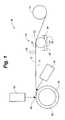
- FIG. 1is a typical schematic view of the filament winding process.
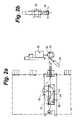
- FIG. 2 ais schematic view of a filament winding layout according to an embodiment of the present invention.
- FIG. 2 bis a partial side view schematic of the filament winding layout of FIG. 2 a.
- FIG. 3is a schematic view of a filament winding layout according to an embodiment of the present invention.
- FIG. 4is a schematic view of the mandrel engaged in a filament winding method according to an embodiment of the present invention.
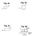
- FIGS. 5 a - dare typical alternative cross-sectional views of the mandrel according to an embodiment of the present invention.
- FIGS. 6 a - bshow the filament winding process according to an embodiment of the present invention.
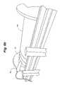
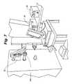
- FIG. 7shows the filament winding process according to an embodiment of the present invention.
- FIG. 8is a perspective view of a mandrel having a racetrack cross section.
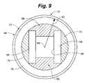
- FIG. 9is an end elevation view of a mandrel having a circular cross section.
- FIG. 10is an end elevation view of a mandrel having a circular cross section having a further configuration of the conductor and insulator components.
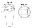
- FIG. 11is a perspective view of an elongate mandrel having conductor and insulator components as depicted in FIG. 9 .
- FIG. 12is an end view of the mandrel of FIG. 11 .
- FIG. 13is an end elevation view of a mandrel having an elliptical cross section.
- FIG. 14is a schematic representation of helical winding with lagging strip irradiators in both winding directions.
- FIG. 15is a graphic depiction of the UV cure of an epoxy based resin formulation 51180J-P impregnating fibers Toray T 1000 12K.
- a fiber bundle 12made up of a plurality of individual fibers 13 , is shown in tension between a fiber spool 14 and a mandrel 16 .
- a torqueis typically applied to the spool 14 to resist the winding of the mandrel, thereby imposing a tension on the fiber bundle 12 .
- This fiber bundle 12may be made of a variety of filamentary materials, such as glass, carbon, or graphite, for example.
- each of the respective fibers 13 comprising the fiber bundle 12are subjected to tension in the range of 1 lb to 20 lb. The tension applied maintains fiber collimation (or straightness) and creates a state of radial stress or “prestress” in a component being wound.
- the fibers 13After being pulled from the fiber spool 14 , the fibers 13 are subjected to a resin impregnator 18 , such as wet-out tank 20 . During this step, fibers 13 are infiltrated with resin 21 . While a typical wet-out tank 20 is described, a variety of other well-known approaches can be employed to infiltrate fiber filaments 13 with resin 21 . In a drum type wet-out tank 20 , such as the one seen in FIG. 3 , the fibers 13 of the fiber bundle 12 are forced into contact with the resin-soaked exterior margin surface 23 of a drum 22 . Drum 22 is generally partially submerged and rotated through a resin bath 24 for this wet-out impregnation.
- a resin impregnator 18such as wet-out tank 20 .
- the resin 21 picked up by the drum 22is consequently transferred to the surface 23 and thence to the fibers 13 of the fiber bundle 12 .
- Feeding the fiber bundle 12 in tension across a drum 22spreads out the respective fibers 13 and allows for adequate resin infiltration, including infiltration into the interstitial spaces in the tow.
- Guide components 26such as bars, rollers or combs may be used to ensure sufficient contact with the surface 23 of the drum 22 is experienced by the fibers 13 . Generally, such guides 26 cause adequate angular contact with the surface 23 of the drum 22 to be effected. Further, an adjustable doctor blade 28 is shown mounted above the resin bath 24 for skimming off excessive resin 21 to achieve the desired resin-to-fiber ratio.
- the resin 21 impregnated upon the fibers 13contains a ultra-violet responsive additive 30 that is useful in the subsequent quasi-instantaneous curing process.
- This additive 30allows curing (polymerization) by an ultra-violet light 32 to quasi-instantly take place, thereby locking in the fiber tension thereby creating the desired prestresses.
- Such additives 30include, but are not limited to: the epoxy based resin formulation 51180J-P made by UV Chemistry Inc. of Torrance, Calif., USA and epoxy based resin formulation EMI 612, made by Electrochemical Materials Inc. See FIG. 15 for a depiction of the UV cure of the epoxy based resin formulation 51180J-P impregnating fibers Toray T 1000 12K as it relates to time.
- the fibers 13are wound in tension around the outer surface of a mandrel 16 . These fibers 13 are wound in a controlled pattern around the outside surface of the mandrel 16 to form a hollow fiber structure 30 . Cylindrical, tapered, or spherical shapes and tubes of various cross-section, length, and diameter can be formed.
- an ultra-violet light source 32is placed generally at the point of tangency of the fibers 13 with the mandrel 16 to effect the quasi-instantaneous curing proximate such point 36 .
- Such curingis virtually totally effective at such point 36 for translucent fibers 13 .
- a heat source 34may be used to further cure the resin coated fiber bundle 12 .
- ultra-violet light source 32is directed to the outside of the wound fibers 13 at the location 36 where the fiber bundle 12 comes into tangential contact with the mandrel 16 . At this point 36 , tangential and radial (normal) stresses are being experienced by the fiber bundle 12 .
- the ultra-violet radiation given off by the light source 32acts to polymerize (solidify) the resin matrix 21 impregnating the fiber bundle 12 in a quasi-instantaneous fashion. Polymerization and curing of the fibers 13 locks in the desirable tangential and radial stresses being experienced continually as the fibers 13 are wound around the mandrel 16 . If not for such rapid curing, resin 21 would flow and migrate thereby causing tension to be lost. This curing is done at a rate even much faster than that done by instant prior art polymerization using heat, and therefore provides a diminished opportunity for resin migration and lost tension.
- a second, optional light source 34is shown in the figures as well.
- This light source 34is preferably directed at the inside (underside) surface of the fiber 13 being wound, at or just prior to the location 36 where the fibers 13 are first in tangential contact 36 with the mandrel 16 .
- the second light source 34may be either a secondary ultra-violet light source or an infrared heat source.
- ultra-violet light curingwill be sufficient.
- opaque fibers 13such as carbon or graphite
- the polymerization processmay need to be augmented by use of infra-red radiative heating to ensure that the initial polymerization is maintained once exposure to ultra-violet light ceases.
- a second ultra-violet light 34may be used to simply augment the ultra-violet cure as the second light source 34 as well. Further, additional post curing of the resulting structure at an elevated temperature may be used to ensure that the resin is fully cured or polymerized.
- FIG. 4shows a more detailed diagram of the mandrel 16 during filament winding operations.
- Ultra-violet light source 32 and secondary light source 34are both directed to the area of fiber bundle 12 at or closely to the location 36 where the fiber 12 comes into tangential contact with the mandrel 16 .
- the fiber bundle 12is coated in liquid resin 21 (containing the ultra-violet responsive additive 30 ) as it approaches the mandrel 16 .
- the subsequent polymerized fiber structure 31surrounds the mandrel 16 . Quasi-in situ curing takes place to cause the transformation between these two states (liquid and solid) and to maintain tension applied to the fibers 13 during the winding process.
- FIGS. 5 a - dset forth examples of possible cross-section shapes for the mandrel 16 .
- the shape used for this mandrel componentwill determine the end shape of the fiber structure part produced in this process in cases where the fiber structure is to be removed from the mandrel 16 .
- round or circular 46 , rectangular 47 , elliptical 48 , or other 50 cross-section shapesare possible.
- the ellipse 48can be distorted to form and oval or egg shape, as desired.
- the shapes 46 , 48are designed to have a largely curved perimeter side so that radial forces can be experienced around the entire perimeter, the exception being a flat-sided cross section such as a square or rectangle 47 and the race track shape 50 . It has been shown to be advantageous to locking in the prestress to have a point of tangency 36 at all points on the perimeter of the mandrel 16 , as is described in greater detail below.
- FIGS. 6 a - b and FIG. 7set forth two different arrangements of equipment to perform the method of the present invention.
- FIGS. 6 a and 6 bshow fiber bundle 12 being wound around a large barrel sized mandrel 16 a suitable as a gin barrel or a rail gun. As illustrated by this set-up, mandrel 16 and resulting structures may be of small or very large sizes.
- An ultra-violet device 32 , infra-red heaters 34 , ultra-violet controller 38 , and infra-red controller 40are depicted mounted proximate the mandrel 16 .
- the ultra-violet device 32 , infra-red heaters 34 , ultra-violet controller 38 , and infra-red controller 40may be easily adjusted and arranged relative to the mandrel 16 and point of tangency 36 to provide an optimal cure configuration for a selected shape component and material. This flexibility and adaptability of configuration has significant advantages over prior art curing methods.
- FIG. 7sets forth an arrangement in which a much smaller mandrel 16 b can be seen. Once again, a very easy to adjust configuration is supplied.
- Ultra-violet light source 32 and ultra-violet power control 38are included to provide the necessary curing as well as a secondary light source 34 and corresponding controller 40 .
- the first stepincludes, providing a plurality of filamentary fibers 13 in a fiber bundle 12 such as from a continuous source, such as spool 14 .
- this materialmay be carbon, graphite, glass, or other suitable material.
- This spool 14 of materialis acted on by a resisting torque to place the filamentary material 13 in tension as winding progresses.
- a usermust impregnate a resin 21 (containing additives that are be caused to polymerize when exposed to ultra-violet light) onto a plurality of fibers 13 of the fiber bundle 12 .
- a resin 21containing additives that are be caused to polymerize when exposed to ultra-violet light
- the fibers 13are then wound on a mandrel 16 , the rotation of the mandrel 16 acting to overcome the resisting torque and to thereby place the fibers 13 in tension.
- the windingis such that the fibers 13 create radial and axial pressure due to the tension applied to the fibers 13 .
- the resin coated fibers 13are then polymerized using ultra-violet light to cure the fibers quasi-instantaneously as the fibers 13 first come into contact with the mandrel 16 at a point of tangency 36 to create a polymerized structure 30 . Radial and tangential stresses are accordingly continuously locked in the resulting mandrel-wound fiber element as the ultra-violet light quasi-instantly cures the resin coated fibers 13 .
- the fiber elementWhen the fiber element is of desired thickness, it may be removed from the mandrel for further curing or use apart from the mandrel.
- the mandrel 16being a gun barrel or rail gun, the polymerized fiber element is left in place to afford greater strength to the gun barrel or rail gun.
- impregnating the fibers 13 with resin 21specifically involves using a wet-out tank 20 to infiltrate fiber filaments 13 with resin 21 , although this impregnation of resin 21 may occur in several well-known manners.
- an infra-red heater 34is used to augment the cure of the resin, in addition to the ultra-violet curing light 32 .
- the solidified, prestressed fiber bundle 12is left in place on the mandrel 16 (the gun barrel or rail gun).
- rail gunsare enhanced by high levels of radial prestress in order to react the magnetic forces which occur in the device.
- repulsive (outward directed) magnetic forcesbe opposed by prestress so that no separation of components that are acted upon by the repulsive magnetic forces occurs. Failing to have this prestress may result in the separation of the conductor and insulator components (noted in the embodiments described below) thereby generating gas plasmas and arcing. Therefore, a filament wound prestressed, solidified fiber bundle 12 helps to ensure that the noted components comprising the rail are held in intimate contact during the application of very high repelling magnetic forces characteristic of such devices when the rail gun is operated.
- Applicantcarried out a series of experiments in which the filament winding and ultra-violet curing technique noted above was evaluated for constructing a rail gun. Among other things, it was demonstrated during the investigation that it is possible to produce in-situ curing of both glass and carbon filaments 13 impregnated with resin matrices 21 and UV additives 30 that can be quasi-instantaneously polymerized using ultra-violet radiation. It was also shown that use of such in-situ curing permits the tension that is induced in the fiber filaments 13 to be maintained since resin migration and the resulting loss of tension that occurs with resin matrices that are not cured quasi instantaneously does not occur. A race track specimen 50 of the mandrel 16 was wound as indicated above. See FIGS.
- the specimen 50has aluminum end caps 52 spaced apart by opposing insulators 54 .
- the insulators 54were preferably composed of high modulus carbon or Nextel insulator material.
- Strain gauges 59were placed adjacent the insulators 54 on the opposed inner margins of the insulators 54 . Winding was performed as indicated by the arrow 44 .
- FIGS. 9-12A first such design that is circular in cross section is disclosed in FIGS. 9-12 .
- FIGS. 11 and 12depict an elongate section of a rail gun.
- FIG. 13is a second such design being an elliptical configuration.
- the embodiments of FIGS. 9-12include a pair of opposed insulators 64 spaced apart by a pair of conductors 66 .
- Side cheeks 70are interposed between the inside margin of the mandrel 16 and the outer margin of the insulators 64 .
- An elongate axial aperture 68is defined by the insulators 64 and conductors 66 in cooperation. Where the mandrel 16 forms a rail gun, a projectile is passed through the axial aperture 68 at extreme velocity.
- the polymerized fiber structure 31is preferably formed of both circumferential and helical wraps, the inner shell 74 being preferably circumferential wrapped and the outer shell 72 preferably being helical wound, as depicted in FIGS. 10 and 13 . Further, preferably, the inner shell 74 of the polymerized fiber structure 31 is formed of Shell S 2 glass epoxy and the outer shell 72 is formed of HM carbon or graphite. The outer shell 72 overlying the inner shell 74 may be autoclaved after the quasi-instantaneous polymerization.
- a feed eye 40feeds the fiber bundle 12 alternately to the right and to the left to lay the fiber bundle 12 alternately in a right helical and a left helical pattern on the rotating mandrel 16 , rotation being as indicated by arrow 44 .
- the strip irradiator 42When moving in the right direction, the strip irradiator 42 also moves to the right, slightly lagging the point of tangential contact 36 . Similar coordinated motion of the feed eye 40 and the irradiator 42 occurs in left sweeps of the feed eye 40 and the irradiator 42 . Such lagging strip irradiator 42 permits laying the resin matrix 21 in both longitudinal directions on the mandrel 16 (rail gun). Accordingly, methods of constructing a rail gun are made possible by the present disclosure.
- Steps for manufacturing a rail gun barrelinclude providing a plurality of fibers 13 that are placed in tension, impregnating a resin 21 containing ultra-violet sensitive additives 30 onto the plurality of fibers 13 , winding the plurality of fibers 13 onto a mandrel 16 that comprises in part the product including a rail gun, and polymerizing fibers 13 quasi-instantaneously using ultra-violet light 32 .
- the general outside configuration of such a productmay preferably be circular or oval in cross section and of considerable length.
- the tension used during the winding processmay be maximized without damage to the fibers 13 .
- Radial prestresshelps to prevent separation of the insulators 64 from the conductors 66 under the influence of the repelling magnetic forces that occur during operation of a rail gun.
- thermosetting resinssuch as in-situ mixing of resin and reactive curing agents.
- Thisis likewise applicable to the prestressing of thermoplastic resins used as matrices in filament winding which typically involves maintenance of tension in the fibers while the previously heated matrix is cooled to lock-in the fiber tension.
Landscapes
- Engineering & Computer Science (AREA)
- General Engineering & Computer Science (AREA)
- Physics & Mathematics (AREA)
- Electromagnetism (AREA)
- Plasma & Fusion (AREA)
- Mechanical Engineering (AREA)
- Moulding By Coating Moulds (AREA)
Abstract
Description
Claims (8)
Priority Applications (1)
| Application Number | Priority Date | Filing Date | Title |
|---|---|---|---|
| US12/415,462US8062453B2 (en) | 2008-04-02 | 2009-03-31 | Method for quasi-instantaneous polymerization of filament wound composite materials |
Applications Claiming Priority (2)
| Application Number | Priority Date | Filing Date | Title |
|---|---|---|---|
| US4181608P | 2008-04-02 | 2008-04-02 | |
| US12/415,462US8062453B2 (en) | 2008-04-02 | 2009-03-31 | Method for quasi-instantaneous polymerization of filament wound composite materials |
Publications (2)
| Publication Number | Publication Date |
|---|---|
| US20100043764A1 US20100043764A1 (en) | 2010-02-25 |
| US8062453B2true US8062453B2 (en) | 2011-11-22 |
Family
ID=41695152
Family Applications (1)
| Application Number | Title | Priority Date | Filing Date |
|---|---|---|---|
| US12/415,462Expired - Fee RelatedUS8062453B2 (en) | 2008-04-02 | 2009-03-31 | Method for quasi-instantaneous polymerization of filament wound composite materials |
Country Status (1)
| Country | Link |
|---|---|
| US (1) | US8062453B2 (en) |
Families Citing this family (3)
| Publication number | Priority date | Publication date | Assignee | Title |
|---|---|---|---|---|
| DE102011111359A1 (en)* | 2011-07-27 | 2013-01-31 | Abdul Amir Shubbar | Device for reinforcing tanks with synthetic resin impregnated fibers |
| US20120138223A1 (en) | 2011-09-29 | 2012-06-07 | General Electric Company | Uv-ir combination curing system and method of use for wind blade manufacture and repair |
| WO2024148043A2 (en)* | 2023-01-04 | 2024-07-11 | Colorado State University Research Foundation | Rapid manufacturing of composite structures using filament winding techniques |
Citations (60)
| Publication number | Priority date | Publication date | Assignee | Title |
|---|---|---|---|---|
| US3019206A (en) | 1958-09-24 | 1962-01-30 | Minnesota Mining & Mfg | Polyblends of a thermoplastic tetrafluoroethylene polymer latex and an elastomeric fluorocarbon polymer latex and article coated therewith |
| US3338992A (en) | 1959-12-15 | 1967-08-29 | Du Pont | Process for forming non-woven filamentary structures from fiber-forming synthetic organic polymers |
| US3341394A (en) | 1966-12-21 | 1967-09-12 | Du Pont | Sheets of randomly distributed continuous filaments |
| US3492187A (en) | 1965-09-23 | 1970-01-27 | Henry J Hirtzer | Filament winding and impregnation mechanism |
| US3502763A (en) | 1962-02-03 | 1970-03-24 | Freudenberg Carl Kg | Process of producing non-woven fabric fleece |
| US3542615A (en) | 1967-06-16 | 1970-11-24 | Monsanto Co | Process for producing a nylon non-woven fabric |
| US3692618A (en) | 1969-10-08 | 1972-09-19 | Metallgesellschaft Ag | Continuous filament nonwoven web |
| US3802817A (en) | 1969-10-01 | 1974-04-09 | Asahi Chemical Ind | Apparatus for producing non-woven fleeces |
| US3837771A (en) | 1972-11-17 | 1974-09-24 | Upjohn Co | Apparatus for producing foamed resin-care web-faced laminates in continuous lengths |
| US3849241A (en) | 1968-12-23 | 1974-11-19 | Exxon Research Engineering Co | Non-woven mats by melt blowing |
| US4340563A (en) | 1980-05-05 | 1982-07-20 | Kimberly-Clark Corporation | Method for forming nonwoven webs |
| US4418123A (en) | 1978-12-06 | 1983-11-29 | H. B. Fuller Company | Extrudable self-adhering elastic and method of employing same |
| US4434562A (en) | 1981-09-02 | 1984-03-06 | American Screen Printing Equipment Company | Curing apparatus and method |
| US4652487A (en) | 1985-07-30 | 1987-03-24 | Kimberly-Clark Corporation | Gathered fibrous nonwoven elastic web |
| US4655760A (en) | 1985-07-30 | 1987-04-07 | Kimberly-Clark Corporation | Elasticized garment and method of making the same |
| US4657802A (en) | 1985-07-30 | 1987-04-14 | Kimberly-Clark Corporation | Composite nonwoven elastic web |
| US4720415A (en) | 1985-07-30 | 1988-01-19 | Kimberly-Clark Corporation | Composite elastomeric material and process for making the same |
| US4781966A (en) | 1986-10-15 | 1988-11-01 | Kimberly-Clark Corporation | Spunlaced polyester-meltblown polyetherester laminate |
| US4789699A (en) | 1986-10-15 | 1988-12-06 | Kimberly-Clark Corporation | Ambient temperature bondable elastomeric nonwoven web |
| US4965122A (en) | 1988-09-23 | 1990-10-23 | Kimberly-Clark Corporation | Reversibly necked material |
| US4981747A (en) | 1988-09-23 | 1991-01-01 | Kimberly-Clark Corporation | Composite elastic material including a reversibly necked material |
| US5011733A (en) | 1985-09-17 | 1991-04-30 | Kansai Paint Co., Ltd. | Process for coating metallic substrate |
| US5226992A (en) | 1988-09-23 | 1993-07-13 | Kimberly-Clark Corporation | Process for forming a composite elastic necked-bonded material |
| US5332613A (en) | 1993-06-09 | 1994-07-26 | Kimberly-Clark Corporation | High performance elastomeric nonwoven fibrous webs |
| US5385775A (en) | 1991-12-09 | 1995-01-31 | Kimberly-Clark Corporation | Composite elastic material including an anisotropic elastic fibrous web and process to make the same |
| US5476567A (en) | 1993-03-26 | 1995-12-19 | Yamaha Gamagori Seizo Kabushiki | Method and apparatus for fabricating resin mats |
| US5514470A (en) | 1988-09-23 | 1996-05-07 | Kimberly-Clark Corporation | Composite elastic necked-bonded material |
| EP0733472A2 (en) | 1995-03-22 | 1996-09-25 | W.R. Grace & Co.-Conn. | Multilayer films for packaging and administering medical solutions |
| US5766357A (en) | 1996-09-19 | 1998-06-16 | Alliant Techsystems Inc. | Apparatus for fiber impregnation |
| US5801128A (en) | 1995-10-23 | 1998-09-01 | International Refining And Manufacturing Company | Hot melt lubricant and method of application |
| US5853881A (en) | 1996-10-11 | 1998-12-29 | Kimberly-Clark Worldwide, Inc. | Elastic laminates with improved hysteresis |
| DE19824804A1 (en) | 1998-06-03 | 1999-12-09 | Voith Sulzer Papiertech Patent | Coating system for one or both sides of a moving paper web |
| US6001460A (en) | 1996-12-30 | 1999-12-14 | Kimberly-Clark Worldwide, Inc. | Elastic laminated fabric material and method of making same |
| US6057024A (en) | 1997-10-31 | 2000-05-02 | Kimberly-Clark Worldwide, Inc. | Composite elastic material with ribbon-shaped filaments |
| US6099685A (en) | 1995-01-12 | 2000-08-08 | Showa Denko K.K. | Extrusion laminating substrate with adhesive of olefin polymer and polyepoxide |
| US6179945B1 (en) | 1998-12-30 | 2001-01-30 | Owens Corning Fiberglas Technology, Inc. | Process for filament winding composite workpieces |
| US6207237B1 (en) | 1998-09-30 | 2001-03-27 | Kimberly-Clark Corporation | Elastic nonwoven webs and films |
| US6242504B1 (en) | 1997-09-29 | 2001-06-05 | Basf Aktiengesellschaft | Crosslinking of radiation-crosslinkable pressure-sensitive adhesive films |
| US6312484B1 (en)* | 1998-12-22 | 2001-11-06 | 3M Innovative Properties Company | Nonwoven abrasive articles and method of preparing same |
| US6323389B1 (en) | 1997-10-03 | 2001-11-27 | Kimberly-Clark Worldwide, Inc. | High performance elastic composite materials made from high molecular weight thermoplastic triblock elastomers |
| US20020019616A1 (en) | 2000-05-15 | 2002-02-14 | Thomas Oomman Painumoottil | Elastomeric laminate with film and strands suitable for a nonwoven garment |
| US6387471B1 (en) | 1999-03-31 | 2002-05-14 | Kimberly-Clark Worldwide, Inc. | Creep resistant composite elastic material with improved aesthetics, dimensional stability and inherent latency and method of producing same |
| US6387179B1 (en) | 1997-06-24 | 2002-05-14 | Hydril Company | Method and device for impregnating fiber bundles with resin |
| US20020064653A1 (en) | 1998-05-18 | 2002-05-30 | Mladen Ladika | Crosslinked elastic fibers |
| US20020147273A1 (en) | 1999-07-28 | 2002-10-10 | Patel Rajen M. | Hydrogenated block copolymers having elasticity and articles made therefrom |
| US6570714B2 (en) | 2000-02-16 | 2003-05-27 | Zms, Llc | Precision composite article |
| US20030124331A1 (en) | 2001-12-28 | 2003-07-03 | Charles Morell | Elastic strand bonded laminate |
| US20040005832A1 (en) | 2002-07-02 | 2004-01-08 | Neculescu Cristian M. | Strand-reinforced composite material |
| EP1246881B1 (en) | 1999-10-29 | 2004-04-07 | Avery Dennison Corporation | Multilayer composite psa constructions |
| US20040123938A1 (en) | 2002-12-26 | 2004-07-01 | Neculescu Cristian M. | Method of making strand-reinforced elastomeric composites |
| US6767852B2 (en) | 2000-12-28 | 2004-07-27 | Kimberly-Clark Worldwide, Inc. | Stretch edge elastic laminate |
| US6783842B2 (en) | 2001-10-25 | 2004-08-31 | Nordenia Deutschland Gronau Gmbh | Multi-layer co-extruded film |
| US6794024B1 (en) | 1999-11-01 | 2004-09-21 | Kimberly-Clark Worldwide, Inc. | Styrenic block copolymer breathable elastomeric films |
| US20040197588A1 (en) | 2003-03-24 | 2004-10-07 | Thomas Oomman Painumoottil | High performance elastic laminates made from high molecular weight styrenic tetrablock copolymer |
| US6808789B2 (en) | 1996-10-10 | 2004-10-26 | The Procter & Gamble Company | Breathable elastic polymeric film laminates |
| US6893529B1 (en) | 1993-10-05 | 2005-05-17 | Tetra Laval Holdings & Finance S.A. | Method of producing a laminate material |
| US20050163960A1 (en) | 2004-01-09 | 2005-07-28 | Lapin Stephen C. | Radiation curable laminating adhesives based on cycloaliphatic carboxylic acid functional monomers |
| US20060055089A1 (en) | 1999-09-17 | 2006-03-16 | Zhang John J | Zoned radiation crosslinked elastomeric materials |
| US7384491B2 (en) | 2005-09-01 | 2008-06-10 | Kimberly-Clark Worldwide, Inc. | Apparatus and methods for making crosslinked elastic laminates |
| US7413623B2 (en) | 2005-02-04 | 2008-08-19 | Rse Industries, Inc. | Apparatus for resin-impregnation of fibers for filament winding |
- 2009
- 2009-03-31USUS12/415,462patent/US8062453B2/ennot_activeExpired - Fee Related
Patent Citations (62)
| Publication number | Priority date | Publication date | Assignee | Title |
|---|---|---|---|---|
| US3019206A (en) | 1958-09-24 | 1962-01-30 | Minnesota Mining & Mfg | Polyblends of a thermoplastic tetrafluoroethylene polymer latex and an elastomeric fluorocarbon polymer latex and article coated therewith |
| US3338992A (en) | 1959-12-15 | 1967-08-29 | Du Pont | Process for forming non-woven filamentary structures from fiber-forming synthetic organic polymers |
| US3502763A (en) | 1962-02-03 | 1970-03-24 | Freudenberg Carl Kg | Process of producing non-woven fabric fleece |
| US3492187A (en) | 1965-09-23 | 1970-01-27 | Henry J Hirtzer | Filament winding and impregnation mechanism |
| US3341394A (en) | 1966-12-21 | 1967-09-12 | Du Pont | Sheets of randomly distributed continuous filaments |
| US3542615A (en) | 1967-06-16 | 1970-11-24 | Monsanto Co | Process for producing a nylon non-woven fabric |
| US3849241A (en) | 1968-12-23 | 1974-11-19 | Exxon Research Engineering Co | Non-woven mats by melt blowing |
| US3802817A (en) | 1969-10-01 | 1974-04-09 | Asahi Chemical Ind | Apparatus for producing non-woven fleeces |
| US3692618A (en) | 1969-10-08 | 1972-09-19 | Metallgesellschaft Ag | Continuous filament nonwoven web |
| US3837771A (en) | 1972-11-17 | 1974-09-24 | Upjohn Co | Apparatus for producing foamed resin-care web-faced laminates in continuous lengths |
| US4418123A (en) | 1978-12-06 | 1983-11-29 | H. B. Fuller Company | Extrudable self-adhering elastic and method of employing same |
| US4340563A (en) | 1980-05-05 | 1982-07-20 | Kimberly-Clark Corporation | Method for forming nonwoven webs |
| US4434562A (en) | 1981-09-02 | 1984-03-06 | American Screen Printing Equipment Company | Curing apparatus and method |
| US4720415A (en) | 1985-07-30 | 1988-01-19 | Kimberly-Clark Corporation | Composite elastomeric material and process for making the same |
| US4657802A (en) | 1985-07-30 | 1987-04-14 | Kimberly-Clark Corporation | Composite nonwoven elastic web |
| US4652487A (en) | 1985-07-30 | 1987-03-24 | Kimberly-Clark Corporation | Gathered fibrous nonwoven elastic web |
| US4655760A (en) | 1985-07-30 | 1987-04-07 | Kimberly-Clark Corporation | Elasticized garment and method of making the same |
| US5011733A (en) | 1985-09-17 | 1991-04-30 | Kansai Paint Co., Ltd. | Process for coating metallic substrate |
| US4781966A (en) | 1986-10-15 | 1988-11-01 | Kimberly-Clark Corporation | Spunlaced polyester-meltblown polyetherester laminate |
| US4789699A (en) | 1986-10-15 | 1988-12-06 | Kimberly-Clark Corporation | Ambient temperature bondable elastomeric nonwoven web |
| US5226992A (en) | 1988-09-23 | 1993-07-13 | Kimberly-Clark Corporation | Process for forming a composite elastic necked-bonded material |
| US4981747A (en) | 1988-09-23 | 1991-01-01 | Kimberly-Clark Corporation | Composite elastic material including a reversibly necked material |
| US4965122A (en) | 1988-09-23 | 1990-10-23 | Kimberly-Clark Corporation | Reversibly necked material |
| US5336545A (en) | 1988-09-23 | 1994-08-09 | Kimberly-Clark Corporation | Composite elastic necked-bonded material |
| US5514470A (en) | 1988-09-23 | 1996-05-07 | Kimberly-Clark Corporation | Composite elastic necked-bonded material |
| US5385775A (en) | 1991-12-09 | 1995-01-31 | Kimberly-Clark Corporation | Composite elastic material including an anisotropic elastic fibrous web and process to make the same |
| US5476567A (en) | 1993-03-26 | 1995-12-19 | Yamaha Gamagori Seizo Kabushiki | Method and apparatus for fabricating resin mats |
| US5332613A (en) | 1993-06-09 | 1994-07-26 | Kimberly-Clark Corporation | High performance elastomeric nonwoven fibrous webs |
| US6893529B1 (en) | 1993-10-05 | 2005-05-17 | Tetra Laval Holdings & Finance S.A. | Method of producing a laminate material |
| US6099685A (en) | 1995-01-12 | 2000-08-08 | Showa Denko K.K. | Extrusion laminating substrate with adhesive of olefin polymer and polyepoxide |
| EP0733472A2 (en) | 1995-03-22 | 1996-09-25 | W.R. Grace & Co.-Conn. | Multilayer films for packaging and administering medical solutions |
| US5801128A (en) | 1995-10-23 | 1998-09-01 | International Refining And Manufacturing Company | Hot melt lubricant and method of application |
| US5766357A (en) | 1996-09-19 | 1998-06-16 | Alliant Techsystems Inc. | Apparatus for fiber impregnation |
| US6808789B2 (en) | 1996-10-10 | 2004-10-26 | The Procter & Gamble Company | Breathable elastic polymeric film laminates |
| US5853881A (en) | 1996-10-11 | 1998-12-29 | Kimberly-Clark Worldwide, Inc. | Elastic laminates with improved hysteresis |
| US6001460A (en) | 1996-12-30 | 1999-12-14 | Kimberly-Clark Worldwide, Inc. | Elastic laminated fabric material and method of making same |
| US6387179B1 (en) | 1997-06-24 | 2002-05-14 | Hydril Company | Method and device for impregnating fiber bundles with resin |
| US6242504B1 (en) | 1997-09-29 | 2001-06-05 | Basf Aktiengesellschaft | Crosslinking of radiation-crosslinkable pressure-sensitive adhesive films |
| US6323389B1 (en) | 1997-10-03 | 2001-11-27 | Kimberly-Clark Worldwide, Inc. | High performance elastic composite materials made from high molecular weight thermoplastic triblock elastomers |
| US6057024A (en) | 1997-10-31 | 2000-05-02 | Kimberly-Clark Worldwide, Inc. | Composite elastic material with ribbon-shaped filaments |
| US20020064653A1 (en) | 1998-05-18 | 2002-05-30 | Mladen Ladika | Crosslinked elastic fibers |
| DE19824804A1 (en) | 1998-06-03 | 1999-12-09 | Voith Sulzer Papiertech Patent | Coating system for one or both sides of a moving paper web |
| US6207237B1 (en) | 1998-09-30 | 2001-03-27 | Kimberly-Clark Corporation | Elastic nonwoven webs and films |
| US6312484B1 (en)* | 1998-12-22 | 2001-11-06 | 3M Innovative Properties Company | Nonwoven abrasive articles and method of preparing same |
| US6179945B1 (en) | 1998-12-30 | 2001-01-30 | Owens Corning Fiberglas Technology, Inc. | Process for filament winding composite workpieces |
| US6387471B1 (en) | 1999-03-31 | 2002-05-14 | Kimberly-Clark Worldwide, Inc. | Creep resistant composite elastic material with improved aesthetics, dimensional stability and inherent latency and method of producing same |
| US20020147273A1 (en) | 1999-07-28 | 2002-10-10 | Patel Rajen M. | Hydrogenated block copolymers having elasticity and articles made therefrom |
| US6777082B2 (en) | 1999-07-28 | 2004-08-17 | The Dow Chemical Company | Hydrogenated block copolymers having elasticity and articles made therefrom |
| US20060055089A1 (en) | 1999-09-17 | 2006-03-16 | Zhang John J | Zoned radiation crosslinked elastomeric materials |
| EP1246881B1 (en) | 1999-10-29 | 2004-04-07 | Avery Dennison Corporation | Multilayer composite psa constructions |
| US6794024B1 (en) | 1999-11-01 | 2004-09-21 | Kimberly-Clark Worldwide, Inc. | Styrenic block copolymer breathable elastomeric films |
| US6570714B2 (en) | 2000-02-16 | 2003-05-27 | Zms, Llc | Precision composite article |
| US20020019616A1 (en) | 2000-05-15 | 2002-02-14 | Thomas Oomman Painumoottil | Elastomeric laminate with film and strands suitable for a nonwoven garment |
| US6767852B2 (en) | 2000-12-28 | 2004-07-27 | Kimberly-Clark Worldwide, Inc. | Stretch edge elastic laminate |
| US6783842B2 (en) | 2001-10-25 | 2004-08-31 | Nordenia Deutschland Gronau Gmbh | Multi-layer co-extruded film |
| US20030124331A1 (en) | 2001-12-28 | 2003-07-03 | Charles Morell | Elastic strand bonded laminate |
| US20040005832A1 (en) | 2002-07-02 | 2004-01-08 | Neculescu Cristian M. | Strand-reinforced composite material |
| US20040123938A1 (en) | 2002-12-26 | 2004-07-01 | Neculescu Cristian M. | Method of making strand-reinforced elastomeric composites |
| US20040197588A1 (en) | 2003-03-24 | 2004-10-07 | Thomas Oomman Painumoottil | High performance elastic laminates made from high molecular weight styrenic tetrablock copolymer |
| US20050163960A1 (en) | 2004-01-09 | 2005-07-28 | Lapin Stephen C. | Radiation curable laminating adhesives based on cycloaliphatic carboxylic acid functional monomers |
| US7413623B2 (en) | 2005-02-04 | 2008-08-19 | Rse Industries, Inc. | Apparatus for resin-impregnation of fibers for filament winding |
| US7384491B2 (en) | 2005-09-01 | 2008-06-10 | Kimberly-Clark Worldwide, Inc. | Apparatus and methods for making crosslinked elastic laminates |
Also Published As
| Publication number | Publication date |
|---|---|
| US20100043764A1 (en) | 2010-02-25 |
Similar Documents
| Publication | Publication Date | Title |
|---|---|---|
| US3700535A (en) | Carbon fiber structure and method of forming same | |
| EP3010701B1 (en) | Component made of a fiber composite material and process for producing same | |
| EP0000734B1 (en) | Method for making rods or tubes having a constant profile of fibre reinforced material | |
| DK3019330T3 (en) | PROCEDURE FOR MANUFACTURING A REINFORCEMENT BAR | |
| DE102005053245A1 (en) | Pressure vessel, hydrogen storage tank and process for making the pressure vessel | |
| FI125355B (en) | Rope for lifting device and method for producing a rope for a lifting device | |
| JP6099039B2 (en) | Manufacturing method of composite container | |
| US6324833B1 (en) | Reinforced composite articles and method of making same | |
| US8062453B2 (en) | Method for quasi-instantaneous polymerization of filament wound composite materials | |
| KR102349380B1 (en) | Apparatus for manufacturing reinforcing bars for concrete and method for manufacturing reinforcing bars using the same | |
| US20050271845A1 (en) | Composite poles with an integral mandrel and methods for making the same | |
| JPS62244621A (en) | Continuous molding of carbon fiber reinforced plastic pipe and device therefor | |
| US5749211A (en) | Fiber-reinforced plastic bar and production method thereof | |
| JP5993342B2 (en) | Composite container manufacturing method and composite container manufacturing system | |
| JPH11348140A (en) | Method for pultrusion of resin-reinforced fiber and pultrusion machine | |
| JP2016166617A (en) | High-pressure tank and method for manufacturing high-pressure tank | |
| JPH0489346A (en) | Concrete reinforcing member and its production | |
| JP6081860B2 (en) | Composite container, composite container manufacturing method, and composite container manufacturing system | |
| EP1446524A1 (en) | A method of manufacturing an elongate structural member | |
| JP2675862B2 (en) | Manufacturing method of fiber-reinforced resin filament with spiral recess | |
| JP2019178702A (en) | High pressure tank and manufacturing method thereof | |
| JP3724593B2 (en) | Method for producing linear fiber reinforced plastic and method for producing fiber reinforced plastic cable | |
| WO2018008652A1 (en) | Composite material, pultrusion device, and pultrusion method | |
| JP2008307720A (en) | Fiber reinforced composite material method and fiber reinforced composite material | |
| GB2159845A (en) | Improvements in and relating to fibre reinforcing tape |
Legal Events
| Date | Code | Title | Description |
|---|---|---|---|
| AS | Assignment | Owner name:BAE SYSTEMS LAND & ARMAMENTS L.P., VIRGINIA Free format text:ASSIGNMENT OF ASSIGNORS INTEREST;ASSIGNOR:JONES, BRIAN H., MR.;REEL/FRAME:026047/0044 Effective date:20080721 | |
| AS | Assignment | Owner name:BAE SYSTEMS LAND & ARMAMENTS L.P., VIRGINIA Free format text:CORRECTIVE ASSIGNMENT TO CORRECT THE ASSIGNEE'S ADDRESS PREVIOUSLY RECORDED ON REEL 026047 FRAME 0044. ASSIGNOR(S) HEREBY CONFIRMS THE REMAINDER OF THE INFORMATION AS RECORDED IN THE ORIGINAL ASSIGNMENT;ASSIGNOR:JONES, BRIAN H., MR.;REEL/FRAME:026112/0144 Effective date:20080721 | |
| AS | Assignment | Owner name:BAE SYSTEMS COMPOSITE STRUCTURES, INC., CALIFORNIA Free format text:ASSIGNMENT OF ASSIGNORS INTEREST;ASSIGNOR:BAE SYSTEMS LAND & ARMAMENTS, L.P.;REEL/FRAME:026213/0472 Effective date:20110427 | |
| STCF | Information on status: patent grant | Free format text:PATENTED CASE | |
| AS | Assignment | Owner name:ENCORE COMPOSITE STRUCTURES, INC., CALIFORNIA Free format text:ASSIGNMENT OF ASSIGNORS INTEREST;ASSIGNOR:BAE SYSTEM LAND & ARMAMENTS, L.P.;REEL/FRAME:028169/0608 Effective date:20110726 | |
| FPAY | Fee payment | Year of fee payment:4 | |
| FEPP | Fee payment procedure | Free format text:MAINTENANCE FEE REMINDER MAILED (ORIGINAL EVENT CODE: REM.); ENTITY STATUS OF PATENT OWNER: LARGE ENTITY | |
| LAPS | Lapse for failure to pay maintenance fees | Free format text:PATENT EXPIRED FOR FAILURE TO PAY MAINTENANCE FEES (ORIGINAL EVENT CODE: EXP.); ENTITY STATUS OF PATENT OWNER: LARGE ENTITY | |
| STCH | Information on status: patent discontinuation | Free format text:PATENT EXPIRED DUE TO NONPAYMENT OF MAINTENANCE FEES UNDER 37 CFR 1.362 | |
| FP | Expired due to failure to pay maintenance fee | Effective date:20191122 |