US8062325B2 - Implantable medical device detachment system and methods of using the same - Google Patents
Implantable medical device detachment system and methods of using the sameDownload PDFInfo
- Publication number
- US8062325B2 US8062325B2US11/461,245US46124506AUS8062325B2US 8062325 B2US8062325 B2US 8062325B2US 46124506 AUS46124506 AUS 46124506AUS 8062325 B2US8062325 B2US 8062325B2
- Authority
- US
- United States
- Prior art keywords
- distal end
- medical device
- engagement member
- implantable medical
- condition
- Prior art date
- Legal status (The legal status is an assumption and is not a legal conclusion. Google has not performed a legal analysis and makes no representation as to the accuracy of the status listed.)
- Active, expires
Links
Images


Classifications
- A—HUMAN NECESSITIES
- A61—MEDICAL OR VETERINARY SCIENCE; HYGIENE
- A61F—FILTERS IMPLANTABLE INTO BLOOD VESSELS; PROSTHESES; DEVICES PROVIDING PATENCY TO, OR PREVENTING COLLAPSING OF, TUBULAR STRUCTURES OF THE BODY, e.g. STENTS; ORTHOPAEDIC, NURSING OR CONTRACEPTIVE DEVICES; FOMENTATION; TREATMENT OR PROTECTION OF EYES OR EARS; BANDAGES, DRESSINGS OR ABSORBENT PADS; FIRST-AID KITS
- A61F2/00—Filters implantable into blood vessels; Prostheses, i.e. artificial substitutes or replacements for parts of the body; Appliances for connecting them with the body; Devices providing patency to, or preventing collapsing of, tubular structures of the body, e.g. stents
- A61F2/95—Instruments specially adapted for placement or removal of stents or stent-grafts
- A—HUMAN NECESSITIES
- A61—MEDICAL OR VETERINARY SCIENCE; HYGIENE
- A61B—DIAGNOSIS; SURGERY; IDENTIFICATION
- A61B17/00—Surgical instruments, devices or methods
- A61B17/12—Surgical instruments, devices or methods for ligaturing or otherwise compressing tubular parts of the body, e.g. blood vessels or umbilical cord
- A61B17/12022—Occluding by internal devices, e.g. balloons or releasable wires
- A61B2017/1205—Introduction devices
- A61B2017/12054—Details concerning the detachment of the occluding device from the introduction device
- A—HUMAN NECESSITIES
- A61—MEDICAL OR VETERINARY SCIENCE; HYGIENE
- A61F—FILTERS IMPLANTABLE INTO BLOOD VESSELS; PROSTHESES; DEVICES PROVIDING PATENCY TO, OR PREVENTING COLLAPSING OF, TUBULAR STRUCTURES OF THE BODY, e.g. STENTS; ORTHOPAEDIC, NURSING OR CONTRACEPTIVE DEVICES; FOMENTATION; TREATMENT OR PROTECTION OF EYES OR EARS; BANDAGES, DRESSINGS OR ABSORBENT PADS; FIRST-AID KITS
- A61F2/00—Filters implantable into blood vessels; Prostheses, i.e. artificial substitutes or replacements for parts of the body; Appliances for connecting them with the body; Devices providing patency to, or preventing collapsing of, tubular structures of the body, e.g. stents
- A61F2/95—Instruments specially adapted for placement or removal of stents or stent-grafts
- A61F2002/9505—Instruments specially adapted for placement or removal of stents or stent-grafts having retaining means other than an outer sleeve, e.g. male-female connector between stent and instrument
- A61F2002/9511—Instruments specially adapted for placement or removal of stents or stent-grafts having retaining means other than an outer sleeve, e.g. male-female connector between stent and instrument the retaining means being filaments or wires
- Y—GENERAL TAGGING OF NEW TECHNOLOGICAL DEVELOPMENTS; GENERAL TAGGING OF CROSS-SECTIONAL TECHNOLOGIES SPANNING OVER SEVERAL SECTIONS OF THE IPC; TECHNICAL SUBJECTS COVERED BY FORMER USPC CROSS-REFERENCE ART COLLECTIONS [XRACs] AND DIGESTS
- Y10—TECHNICAL SUBJECTS COVERED BY FORMER USPC
- Y10T—TECHNICAL SUBJECTS COVERED BY FORMER US CLASSIFICATION
- Y10T29/00—Metal working
- Y10T29/49—Method of mechanical manufacture
- Y10T29/49826—Assembling or joining
Definitions
- This inventiongenerally relates to interventional medical device systems that are navigable through body vessels of a human subject. More particularly, this invention relates to detachment systems for deploying an implantable medical device to a target location of a body vessel and methods of using the same.
- catheter delivery systemsfor positioning and deploying therapeutic devices, such as dilation balloons, stents and embolic coils, in the vasculature of the human body has become a standard procedure for treating endovascular diseases. It has been found that such devices are particularly useful in treating areas where traditional operational procedures are impossible or pose a great risk to the patient, for example in the treatment of aneurysms in cranial blood vessels. Due to the delicate tissue surrounding cranial blood vessels, especially for example brain tissue, it is very difficult and often risky to perform surgical procedures to treat defects of the cranial blood vessels. Advancements in catheter deployment systems have provided an alternative treatment in such cases. Some of the advantages of catheter delivery systems are that they provide methods for treating blood vessels by an approach that has been found to reduce the risk of trauma to the surrounding tissue, and they also allow for treatment of blood vessels that in the past would have been considered inoperable.
- these proceduresinvolve inserting the distal end of a delivery catheter into the vasculature of a patient and guiding it through the vasculature to a predetermined delivery site.
- a vascular occlusion devicesuch as an embolic coil, is attached to the end of a delivery member which pushes the coil through the catheter and out of the distal end of the catheter into the delivery site.
- control wireis moved proximally to disengage the clasps from each other.
- the systemdoes not include any positive means for separating the disengaged clasps from each other, so merely retracting the control wire does not ensure release and deployment of the coil.
- Numerous other detachment systems currently in usesuffer from similar problems.
- a detachment systemfor delivering an implantable medical device to a target location of a body vessel is provided with a generally hollow tubular carrier member having a distal end and an engagement member associated with the distal end.
- the distal endincludes a compressible portion that is axially movable from a compressed condition to an elongated condition.
- the engagement memberis adapted to engage an implantable medical device when the compressible portion is in the compressed condition. Movement of the compressible portion to the elongated condition causes an implantable device engaged by the engagement member to be actively separated from the engagement member and deployed to the target location of the body vessel.
- a method of connecting an implantable medical device to a detachment systemincludes providing a generally hollow tubular carrier member.
- the carrier memberhas a distal end with a compressible portion that is axially movable from an elongated condition to a compressed condition.
- the compressible portionis moved to the compressed condition to expose at least a portion of an engagement member associated with the distal end.
- the exposed portion of the engagement memberis then connected to an implantable medical device.
- a method of deploying an implantable medical device to a detachment systemincludes providing a generally hollow tubular carrier member.
- the carrier memberhas a distal end with a compressible portion in a compressed condition.
- An engagement member associated with the distal endis releasably connected to an implantable medical device.
- the thusly provided systemis introduced into a body vessel and the implantable medical device is positioned generally adjacent to a target location of the vessel. When the implantable medical device is properly positioned, it is disengaged from the engagement member, which causes the compressible portion of the carrier member to axially elongate and actively deploy the implantable medical device.
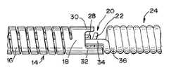
- FIG. 1is a front elevational view of a carrier member of a detachment system according to an aspect of the present invention, in an elongated condition;
- FIG. 1Ais a bottom plan detail view of an anchor portion of the carrier member of FIG. 1 ;
- FIG. 2is a front perspective detail view of a distal end of the carrier member of FIG. 1 ;
- FIG. 3is a front elevational view of the carrier member of FIG. 1 , in a compressed condition
- FIG. 4is a front perspective detail view of a distal end of the carrier member of FIG. 3 ;
- FIG. 5is a front perspective view of a carrier member having a pusher portion according to an alternative embodiment
- FIG. 6is a plan view of an engagement member according to an alternative embodiment
- FIG. 7is a front perspective detail view of the opening of the engagement member of FIG. 6 , in an up-turned condition;
- FIG. 8is a front perspective view of the distal end of the carrier member of FIG. 1 and a rear perspective view of an implantable medical device in a pre-connection condition;
- FIG. 9is a front elevational view of a connection step for connecting the distal end and implantable medical device of FIG. 8 ;
- FIG. 9 ais a front elevational view of the proximal end of the pusher portion of FIG. 5 and illustrating a connection step by which the distal end of the pusher engages the proximal portion of the implantable medical device;
- FIG. 10is a front perspective detail view of the distal end of the carrier member and a rear perspective view of the implantable medical device of FIG. 8 , in a connected condition;
- FIG. 11is a plan view of the distal end of the carrier member and proximal end of the implantable medical device of FIG. 8 , in a disengaged condition;
- FIG. 12is a front perspective view of a head piece for an implantable medical device.
- FIGS. 1-4illustrate a distal portion of a generally hollow or tubular structure according to the present invention.
- tubularand “tube” are to be construed broadly and are not limited to a structure that is a right cylinder or strictly circumferential in cross-section or of a uniform cross-section throughout its length.
- the tubular structure or systemis generally designated at 10 and shown as a substantially right cylindrical structure.
- the tubular systemmay have a tapered or curved outer surface without departing from the scope of the present invention.
- the detachment system 10is comprised of a generally hollow tubular carrier member 12 having a distal end portion 14 with a compressible portion 16 and a pusher portion 18 .
- the carrier member 12is a hypotube that may be comprised of a biocompatible material, such as stainless steel.
- the hypotubetypically will have a diameter of between about 0.010 inch and about 0.015 inch, a preferred tube having a diameter of approximately 0.013 inch.
- Such a carrier member 12is suitable for delivering and deploying embolic coils to target locations, typically aneurysms, within the neurovasculature, but differently sized carrier members comprised of other materials may be useful for different applications and are within the scope of the present invention.
- the compressible portion 16 of the distal end portion 14is axially adjustable between an elongated condition ( FIGS. 1 and 2 ) and a compressed condition ( FIGS. 3 and 4 ).
- the compressible portion 16comprises a spiral-cut portion of the carrier member 12 , formed by a laser-cutting operation.
- any other arrangement allowing axial adjustmente.g., a wound wire or spiral ribbon
- the compressible portion 16is in the elongated condition at rest and automatically or resiliently returns to the elongated condition from the compressed condition, unless otherwise constrained. The function of the compressible portion 16 will be described in greater detail herein.
- the distal end 14When the compressible portion 16 is in the elongated condition, the distal end 14 receives and shields at least a portion of an engagement member 20 , as shown in FIG. 2 .
- the engagement member 20is relatively small, having the thickness of a hair in some embodiments, so it may be preferred for it to be entirely shielded by the distal end 14 to prevent damage from accidental contact.
- the engagement member 20comprises an elongated wire loosely bent in half to define an opening 22 .
- the ends 23 of the engagement member 20are fixedly connected to the carrier member 12 at a position proximal to the compressible portion 16 , for example at an anchor portion 26 ( FIG. 1A ).
- the engagement member 20 acomprises a flat ribbon defining an opening 22 a at a distal portion thereof.
- FIG. 7shows the opening 22 a in an up-turned condition suitable for engaging an implantable medical device 24 , as shown in FIGS. 9 and 10 and described in greater detail herein.
- the engagement member 20 of FIGS. 1-4is preferably similarly deformable to the up-turned condition of FIGS. 9 and 10 .
- the engagement member 20 , 20 ais elastically deformable to the up-turned condition of FIGS. 7 , 9 , and 10 , such that it will return to the substantially flat condition of FIGS. 1-4 and 6 when not otherwise constrained.
- the engagement member 20 , 20 amay be comprised of any of a number of materials, including nitinol and stainless steel. The function of the engagement member 20 , 20 a will be described in greater detail herein.
- the detachment system 10further includes a locking member 26 received within the lumen of the carrier member 12 and movable with respect to the engagement member 20 .
- the locking member 28is preferably substantially longer than the engagement member 20 , stretching beyond the anchor portion 26 to at least a proximal end portion (not illustrated) of the carrier member 12 .
- the locking member 28stretches beyond a proximal end of the carrier member 12 to be directly manipulated by the user.
- the locking member 28may be a wire comprised of any of a number of materials, including nitinol. The function of the locking member 28 will be described in greater detail herein.
- the pusher portion 18is positioned adjacent to and distally of the compressible portion 16 . As shown in FIGS. 1-4 , the pusher portion 18 preferably is not a simple right cylindrical member, but is a modified cylinder having a slot-like component, being defined by two arcuate extensions 30 and 32 .
- the two extensions 30 , 32 of the pusher portion 18accommodate therebetween an aperture-defining proximal end portion 34 of an implantable medical device 24 , which may be wider than the lumen of the carrier member 12 , as shown in FIG. 11 .
- the spacing that separates the two arcuate extensions 30 and 32accommodates the proximal end member 34 and allows the engagement member 20 to engage the implantable medical device 24 ( FIGS. 9 and 10 ), as described in greater detail herein.
- the engaged implantable medical device 24may be rotated by rotating the carrier member 12 until at least one of the arcuate extensions 30 , 32 bears against and turns the aperture-containing proximal end member 34 of the implantable medical device 24 .
- the arcuate extensions 30 and 32 of FIGS. 1-4 and 8 - 11are illustrated with different lengths. As shown in FIG. 9 , this creates a gap between the first arcuate extension 30 and a proximal end portion 36 of the implantable medical device 24 , which may simplify connection of the device 24 , as will be described in greater detail herein. However, according to an alternative embodiment of FIG. 5 , the arcuate extensions 30 and 32 may have the same length without departing from the scope of the present invention. The function of the pusher portion 18 will be described in greater detail herein.
- an embolic coil having a proximal end portion 36 with an aperture 34is illustrated in FIGS. 8-11 .
- FIGS. 8-11an embolic coil having a proximal end portion 36 with an aperture 34.
- the compressible portion 16 of the carrier member 12is shortened in axial length to a compressed condition ( FIGS. 3 and 4 ) to expose at least a portion of the engagement member 20 .
- FIG. 3shows a distance “D” by which the carrier member 12 is axially foreshortened in moving the compressible portion 16 from the elongated condition to the compressed condition. If the locking member 28 of the carrier member 12 is oriented to extend beyond the engagement member 20 , as shown in FIGS. 3 and 4 , it is withdrawn into the carrier member 12 sufficiently to position it clear of at least a portion of the opening 22 of the engagement member 20 ( FIG. 9 ).
- the aperture-containing proximal end member 34 of the implantable medical device 24is placed adjacent to opening 22 , which is then deformed to the up-turned condition of FIG. 9 .
- the opening 22may be moved to the up-turned condition prior to placement of the implantable medical device 24 .
- the up-turned conditionat least a portion of the opening 22 passes through the aperture-containing portion 34 , as best shown in FIG. 10 .
- a head piece 38may be affixed to a proximal end portion thereof ( FIG. 12 ) to provide an aperture 34 a to receive the engagement member 20 .
- first arcuate extension 30 of the pusher portion 18is relatively short compared to the second arcuate extension 32 , then the second extension 32 will bear against the implantable medical device 24 , while a gap is defined between the device 24 and the first arcuate extension 30 , as illustrated in FIG. 9 .
- the gapallows improved access to the engagement member 20 , thereby simplifying movement thereof through the aperture 34 of the implantable medical device 24 .
- the engagement member 20is preferably elastically deformable to the up-turned condition of FIG. 9 , so it will tend to return to a substantially flat condition.
- the locking member 28is moved axially through the opening 22 to the position of FIG. 10 .
- the locking member 28holds the engagement member 20 in the up-turned condition, and the engagement member 20 holds the proximal end portion 36 of the implantable medical device 24 against at least one arcuate extent 30 , 32 of the pusher portion 18 , preventing the compressible portion 16 from moving to the elongated condition.
- Such an engagement systemmay be incorporated into the present invention by orienting the engaged embolic coil to bear against the pusher portion 18 and hold the compressible portion 16 in the compressed condition while the adhesive is intact.
- the adhesiveshould be sufficiently strong to prevent release by the force of the compressible portion 16 acting on the embolic coil through the pusher portion 18 .
- a device thus engagedis preferably delivered to a target location within a body vessel by a separate catheter or introducer.
- a tubular catheteris fed into a body vessel until a distal end thereof is adjacent to a target location.
- the detachment system 10 and associated implantable medical device 24are advanced through the catheter until the device 24 is itself generally adjacent to the target location.
- the detachment system 10 and associated device 24may be pre-loaded in the catheter, with the combination being fed through a body vessel to a target location.
- Other methods of positioning the implantable medical device 24 generally adjacent to a target locationmay also be practiced without departing from the scope of the present invention.
- radiopaque markersmay be attached to the carrier member 12 or the device 24 itself.
- the engaged device 24When the engaged device 24 has been properly positioned and oriented, it is disengaged from the engagement member 20 . In the illustrated embodiment, this is achieved by moving the locking member 28 proximally from the position of FIG. 10 to the position of FIG. 9 . In the position of FIG. 9 , the engagement member 20 is allowed to return to its original substantially flat condition ( FIGS. 3 and 4 ), thereby disengaging the aperture-containing end portion 34 of the implantable medical device 24 .
- the locking member 28may be provided with a radiopaque portion to provide visual feedback to indicate when the device 24 has been released.
- the carrier member 28may include a proximal portion with an elongatable portion defined by a series of alternating cut sections and frangible bridge members arranged in a spiral or helical pattern.
- a proximal end of the locking member 28(not illustrated) is fixedly attached to the carrier member 12 at a location proximal to the elongatable portion.
- the elongatable portionis elongated by a user, thereby retracting the locking member 28 .
- the locking member 28is adapted such that it will not disengage the engagement member 20 until a sufficient pull force is applied to break the frangible bridge members and more fully elongate the elongatable portion.
- Such an embodimentfunctions as a safety mechanism, because the implantable medical device 24 cannot be released until a minimum pull force is applied by the user.
- the compressible portion 16automatically or resiliently moves from the compressed condition of FIG. 9 to the elongated condition of FIG. 11 .
- At least one of the arcuate extensions 30 , 32 of the pusher portion 18bears against the device 24 , completely separating it from the engagement member 20 .
- the pusher portion 18bears against the proximal end portion 36 of the device 24 without contacting the aperture-containing proximal end portion 34 , as illustrated in FIG. 10 , because the proximal end portion 36 is typically sturdier than the aperture 34 .
- First arcuate extension 30has a distal end surface that engages an upper edge (as viewed in FIG. 9 a ) of the distal-most turn of the device 24 (or a distal-most surface of a portion of some other device to be implanted). This engagement securely holds the device and protects the rest of the device, especially the extending portion 34 , during disengagement. It also is contemplated that the second arcuate extension 32 has a distal end surface that engages a lower edge (as viewed in FIG.
- the force of the compressible portion 16 automatically or resiliently moving from the compressed condition to the elongated conditionwill force the implantable medical device 24 some distance from the engagement member 20 , as shown in FIG. 11 .
- the distanceis exaggerated in FIG. 11 for illustrative purposes, as the compressible portion 16 is preferably calibrated such that its elongation will move the device 24 away from the engagement member 20 without expelling the same a significant distance from the pusher portion 18 .
- detachment systems according to the present inventioneliminate numerous problems associated with known devices.
- detachment systems and associated methods of use according to the present inventionensure that the implantable device is completely separated from the engagement system and deployed to the target location.
Landscapes
- Health & Medical Sciences (AREA)
- Engineering & Computer Science (AREA)
- Biomedical Technology (AREA)
- Cardiology (AREA)
- Oral & Maxillofacial Surgery (AREA)
- Transplantation (AREA)
- Heart & Thoracic Surgery (AREA)
- Vascular Medicine (AREA)
- Life Sciences & Earth Sciences (AREA)
- Animal Behavior & Ethology (AREA)
- General Health & Medical Sciences (AREA)
- Public Health (AREA)
- Veterinary Medicine (AREA)
- Surgical Instruments (AREA)
Abstract
Description
Claims (11)
Priority Applications (2)
| Application Number | Priority Date | Filing Date | Title |
|---|---|---|---|
| US11/461,245US8062325B2 (en) | 2006-07-31 | 2006-07-31 | Implantable medical device detachment system and methods of using the same |
| US13/276,651US20120035707A1 (en) | 2006-07-31 | 2011-10-19 | Methods of using implantable medical device detachment system |
Applications Claiming Priority (1)
| Application Number | Priority Date | Filing Date | Title |
|---|---|---|---|
| US11/461,245US8062325B2 (en) | 2006-07-31 | 2006-07-31 | Implantable medical device detachment system and methods of using the same |
Related Child Applications (1)
| Application Number | Title | Priority Date | Filing Date |
|---|---|---|---|
| US13/276,651DivisionUS20120035707A1 (en) | 2006-07-31 | 2011-10-19 | Methods of using implantable medical device detachment system |
Publications (2)
| Publication Number | Publication Date |
|---|---|
| US20080097462A1 US20080097462A1 (en) | 2008-04-24 |
| US8062325B2true US8062325B2 (en) | 2011-11-22 |
Family
ID=39318990
Family Applications (2)
| Application Number | Title | Priority Date | Filing Date |
|---|---|---|---|
| US11/461,245Active2030-09-22US8062325B2 (en) | 2006-07-31 | 2006-07-31 | Implantable medical device detachment system and methods of using the same |
| US13/276,651AbandonedUS20120035707A1 (en) | 2006-07-31 | 2011-10-19 | Methods of using implantable medical device detachment system |
Family Applications After (1)
| Application Number | Title | Priority Date | Filing Date |
|---|---|---|---|
| US13/276,651AbandonedUS20120035707A1 (en) | 2006-07-31 | 2011-10-19 | Methods of using implantable medical device detachment system |
Country Status (1)
| Country | Link |
|---|---|
| US (2) | US8062325B2 (en) |
Cited By (76)
| Publication number | Priority date | Publication date | Assignee | Title |
|---|---|---|---|---|
| US20070276415A1 (en)* | 2006-03-31 | 2007-11-29 | Nmt Medical, Inc. | Screw catch mechanism for PFO occluder and method of use |
| US20080039743A1 (en)* | 2006-08-09 | 2008-02-14 | Coherex Medical, Inc. | Methods for determining characteristics of an internal tissue opening |
| US20080039929A1 (en)* | 2006-08-09 | 2008-02-14 | Coherex Medical, Inc. | Devices for reducing the size of an internal tissue opening |
| US8434490B2 (en)* | 2008-04-25 | 2013-05-07 | Conceptus, Inc. | Devices and methods for occluding a fallopian tube |
| US20140058435A1 (en)* | 2012-08-21 | 2014-02-27 | Donald K. Jones | Implant delivery and release system |
| US8945171B2 (en) | 2011-09-29 | 2015-02-03 | Covidien Lp | Delivery system for implantable devices |
| US9005242B2 (en) | 2007-04-05 | 2015-04-14 | W.L. Gore & Associates, Inc. | Septal closure device with centering mechanism |
| US20150230802A1 (en)* | 2014-02-14 | 2015-08-20 | Cook Medical Technologies Llc | Stable screw-type detachment mechanism |
| US9149263B2 (en) | 2003-07-14 | 2015-10-06 | W. L. Gore & Associates, Inc. | Tubular patent foramen ovale (PFO) closure device with catch system |
| US9282971B2 (en) | 2013-03-14 | 2016-03-15 | Incumedx, Inc. | Implants, methods of manufacturing the same, and devices and methods for delivering the implants to a vascular disorder of a patient |
| US9326759B2 (en) | 2003-07-14 | 2016-05-03 | W.L. Gore & Associates, Inc. | Tubular patent foramen ovale (PFO) closure device with catch system |
| US9474517B2 (en) | 2008-03-07 | 2016-10-25 | W. L. Gore & Associates, Inc. | Heart occlusion devices |
| US20170007402A1 (en)* | 2014-02-18 | 2017-01-12 | Medtentia International Ltd Oy | Medical Device for a Cardiac Valve Implant |
| US9579104B2 (en) | 2011-11-30 | 2017-02-28 | Covidien Lp | Positioning and detaching implants |
| US9585644B2 (en) | 2006-08-09 | 2017-03-07 | Coherex Medical, Inc. | Devices for reducing the size of an internal tissue opening |
| US9662120B2 (en) | 2013-08-23 | 2017-05-30 | Cook Medical Technologies Llc | Detachable treatment device delivery system utilizing compression at attachment zone |
| US9770232B2 (en) | 2011-08-12 | 2017-09-26 | W. L. Gore & Associates, Inc. | Heart occlusion devices |
| US9808230B2 (en) | 2014-06-06 | 2017-11-07 | W. L. Gore & Associates, Inc. | Sealing device and delivery system |
| US9814562B2 (en) | 2009-11-09 | 2017-11-14 | Covidien Lp | Interference-relief type delivery detachment systems |
| US9861346B2 (en) | 2003-07-14 | 2018-01-09 | W. L. Gore & Associates, Inc. | Patent foramen ovale (PFO) closure device with linearly elongating petals |
| US9918718B2 (en) | 2014-08-08 | 2018-03-20 | DePuy Synthes Products, Inc. | Embolic coil delivery system with retractable mechanical release mechanism |
| US9936957B2 (en) | 2011-12-02 | 2018-04-10 | Incumedx, Inc. | Micro-coil assembly |
| US10052108B2 (en) | 2015-10-30 | 2018-08-21 | Incumedx, Inc. | Devices and methods for delivering an implant to a vascular disorder |
| US10076336B2 (en) | 2013-03-15 | 2018-09-18 | Covidien Lp | Delivery and detachment mechanisms for vascular implants |
| EP3501427A1 (en) | 2017-12-21 | 2019-06-26 | DePuy Synthes Products, Inc. | Implantable medical device detachment system with split tube and cylindrical coupling |
| EP3560439A1 (en) | 2018-04-27 | 2019-10-30 | DePuy Synthes Products, Inc. | Implantable medical device detachment system with split tube |
| US10531877B2 (en) | 2017-11-09 | 2020-01-14 | Inceptus Medical LLC | Interlocking loop coupling/decoupling system for deploying vascular implant devices |
| EP3628242A1 (en) | 2018-09-25 | 2020-04-01 | DePuy Synthes Products, Inc. | Intrasaccular device positioning and deployment system |
| US10792025B2 (en) | 2009-06-22 | 2020-10-06 | W. L. Gore & Associates, Inc. | Sealing device and delivery system |
| US10806437B2 (en) | 2009-06-22 | 2020-10-20 | W. L. Gore & Associates, Inc. | Sealing device and delivery system |
| US10828019B2 (en) | 2013-01-18 | 2020-11-10 | W.L. Gore & Associates, Inc. | Sealing device and delivery system |
| US10856882B2 (en)* | 2014-02-06 | 2020-12-08 | Boston Scientific Scimed, Inc. | Occlusion device |
| EP3753529A1 (en) | 2019-06-18 | 2020-12-23 | DePuy Synthes Products, Inc. | Pull wire detachment for intravascular devices |
| US10939915B2 (en) | 2018-05-31 | 2021-03-09 | DePuy Synthes Products, Inc. | Aneurysm device and delivery system |
| US11058430B2 (en)* | 2018-05-25 | 2021-07-13 | DePuy Synthes Products, Inc. | Aneurysm device and delivery system |
| US11076861B2 (en)* | 2018-10-12 | 2021-08-03 | DePuy Synthes Products, Inc. | Folded aneurysm treatment device and delivery method |
| US11076860B2 (en) | 2014-03-31 | 2021-08-03 | DePuy Synthes Products, Inc. | Aneurysm occlusion device |
| US11090055B2 (en) | 2015-10-30 | 2021-08-17 | Incumedx Inc. | Devices and methods for delivering an implant to a vascular disorder |
| US11134953B2 (en) | 2019-02-06 | 2021-10-05 | DePuy Synthes Products, Inc. | Adhesive cover occluding device for aneurysm treatment |
| US11147562B2 (en) | 2018-12-12 | 2021-10-19 | DePuy Synthes Products, Inc. | Systems and methods for embolic implant detachment |
| US11154302B2 (en) | 2014-03-31 | 2021-10-26 | DePuy Synthes Products, Inc. | Aneurysm occlusion device |
| US11207494B2 (en) | 2019-07-03 | 2021-12-28 | DePuy Synthes Products, Inc. | Medical device delivery member with flexible stretch resistant distal portion |
| US11272939B2 (en) | 2018-12-18 | 2022-03-15 | DePuy Synthes Products, Inc. | Intrasaccular flow diverter for treating cerebral aneurysms |
| US11278292B2 (en) | 2019-05-21 | 2022-03-22 | DePuy Synthes Products, Inc. | Inverting braided aneurysm treatment system and method |
| US11337706B2 (en) | 2019-03-27 | 2022-05-24 | DePuy Synthes Products, Inc. | Aneurysm treatment device |
| US11376013B2 (en) | 2019-11-18 | 2022-07-05 | DePuy Synthes Products, Inc. | Implant delivery system with braid cup formation |
| US11406392B2 (en) | 2018-12-12 | 2022-08-09 | DePuy Synthes Products, Inc. | Aneurysm occluding device for use with coagulating agents |
| US11413046B2 (en) | 2019-05-21 | 2022-08-16 | DePuy Synthes Products, Inc. | Layered braided aneurysm treatment device |
| US11426174B2 (en) | 2019-10-03 | 2022-08-30 | DePuy Synthes Products, Inc. | Medical device delivery member with flexible stretch resistant mechanical release |
| US11432822B2 (en) | 2020-02-14 | 2022-09-06 | DePuy Synthes Products, Inc. | Intravascular implant deployment system |
| US11439403B2 (en) | 2019-09-17 | 2022-09-13 | DePuy Synthes Products, Inc. | Embolic coil proximal connecting element and stretch resistant fiber |
| US11457922B2 (en) | 2020-01-22 | 2022-10-04 | DePuy Synthes Products, Inc. | Medical device delivery member with flexible stretch resistant distal portion |
| US11457926B2 (en) | 2019-12-18 | 2022-10-04 | DePuy Synthes Products, Inc. | Implant having an intrasaccular section and intravascular section |
| US11497504B2 (en) | 2019-05-21 | 2022-11-15 | DePuy Synthes Products, Inc. | Aneurysm treatment with pushable implanted braid |
| US11583282B2 (en) | 2019-05-21 | 2023-02-21 | DePuy Synthes Products, Inc. | Layered braided aneurysm treatment device |
| US11583288B2 (en) | 2018-08-08 | 2023-02-21 | DePuy Synthes Products, Inc. | Delivery of embolic braid |
| US11596412B2 (en) | 2018-05-25 | 2023-03-07 | DePuy Synthes Products, Inc. | Aneurysm device and delivery system |
| US11602350B2 (en) | 2019-12-05 | 2023-03-14 | DePuy Synthes Products, Inc. | Intrasaccular inverting braid with highly flexible fill material |
| EP4147650A1 (en) | 2021-09-09 | 2023-03-15 | DePuy Synthes Products, Inc. | Implantable medical device detachment system with split tube and cylindrical coupling |
| US11607226B2 (en) | 2019-05-21 | 2023-03-21 | DePuy Synthes Products, Inc. | Layered braided aneurysm treatment device with corrugations |
| US11672542B2 (en) | 2019-05-21 | 2023-06-13 | DePuy Synthes Products, Inc. | Aneurysm treatment with pushable ball segment |
| US11672540B2 (en) | 2018-01-24 | 2023-06-13 | DePuy Synthes Products, Inc. | Aneurysm device and delivery system |
| US11672543B2 (en) | 2017-02-23 | 2023-06-13 | DePuy Synthes Products, Inc. | Aneurysm method and system |
| US11844490B2 (en) | 2021-12-30 | 2023-12-19 | DePuy Synthes Products, Inc. | Suture linkage for inhibiting premature embolic implant deployment |
| US11937824B2 (en) | 2021-12-30 | 2024-03-26 | DePuy Synthes Products, Inc. | Implant detachment systems with a modified pull wire |
| US11937826B2 (en) | 2022-03-14 | 2024-03-26 | DePuy Synthes Products, Inc. | Proximal link wire for preventing premature implant detachment |
| US11937825B2 (en) | 2022-03-02 | 2024-03-26 | DePuy Synthes Products, Inc. | Hook wire for preventing premature embolic implant detachment |
| US11951026B2 (en) | 2020-06-30 | 2024-04-09 | DePuy Synthes Products, Inc. | Implantable medical device detachment system with flexible braid section |
| US11998213B2 (en) | 2021-07-14 | 2024-06-04 | DePuy Synthes Products, Inc. | Implant delivery with modified detachment feature and pull wire engagement |
| US12011171B2 (en) | 2022-01-06 | 2024-06-18 | DePuy Synthes Products, Inc. | Systems and methods for inhibiting premature embolic implant deployment |
| US12064156B2 (en) | 2023-01-09 | 2024-08-20 | John F. Krumme | Dynamic compression fixation devices |
| US12127743B2 (en) | 2020-09-23 | 2024-10-29 | DePuy Synthes Products, Inc. | Inverting braided aneurysm implant with dome feature |
| US12137915B2 (en) | 2022-03-03 | 2024-11-12 | DePuy Synthes Products, Inc. | Elongating wires for inhibiting premature implant detachment |
| US12376859B2 (en) | 2019-09-17 | 2025-08-05 | DePuy Synthes Products, Inc. | Embolic coil proximal connecting element and stretch resistant fiber |
| US12396730B2 (en) | 2022-09-28 | 2025-08-26 | DePuy Synthes Products, Inc. | Braided implant with detachment mechanism |
| US12402886B2 (en) | 2022-06-23 | 2025-09-02 | DePuy Synthes Products, Inc. | Detachment indicator for implant deployment |
Families Citing this family (31)
| Publication number | Priority date | Publication date | Assignee | Title |
|---|---|---|---|---|
| DE502004008712D1 (en) | 2004-09-22 | 2009-01-29 | Dendron Gmbh | MEDICAL IMPLANT |
| ATE448737T1 (en) | 2004-09-22 | 2009-12-15 | Dendron Gmbh | DEVICE FOR IMPLANTING MICROWL COILS |
| JP5230602B2 (en) | 2006-04-17 | 2013-07-10 | タイコ ヘルスケア グループ リミテッド パートナーシップ | System and method for mechanically positioning an endovascular implant |
| US8777979B2 (en) | 2006-04-17 | 2014-07-15 | Covidien Lp | System and method for mechanically positioning intravascular implants |
| US8366720B2 (en) | 2006-07-31 | 2013-02-05 | Codman & Shurtleff, Inc. | Interventional medical device system having an elongation retarding portion and method of using the same |
| CA2680607C (en) | 2007-03-13 | 2015-07-14 | Microtherapeutics, Inc. | An implant including a coil and a stretch-resistant member |
| US8801747B2 (en) | 2007-03-13 | 2014-08-12 | Covidien Lp | Implant, a mandrel, and a method of forming an implant |
| US8795316B2 (en) | 2007-04-25 | 2014-08-05 | DePuy Syntheses Products, LLC | Implantable medical device delivery system with a frangible portion and methods of making and using the same |
| US8197442B2 (en) | 2007-04-27 | 2012-06-12 | Codman & Shurtleff, Inc. | Interventional medical device system having a slotted section and radiopaque marker and method of making the same |
| DE102007038446A1 (en)* | 2007-08-14 | 2009-02-19 | pfm Produkte für die Medizin AG | Embolisiereinrichtung |
| EP2633823B1 (en)* | 2008-04-21 | 2016-06-01 | Covidien LP | Braid-ball embolic devices and delivery systems |
| US8333796B2 (en) | 2008-07-15 | 2012-12-18 | Penumbra, Inc. | Embolic coil implant system and implantation method |
| WO2010068814A1 (en) | 2008-12-10 | 2010-06-17 | Boston Scientific Scimed, Inc. | Introducer sheath with an embolic coil device and methods for making the same |
| AU2010236349B2 (en)* | 2009-04-15 | 2015-04-02 | Microvention, Inc. | Implant delivery system |
| US8257422B2 (en)* | 2009-08-19 | 2012-09-04 | Cook Medical Technologies Llc | Over-the-wire detachment mechanism |
| US8911487B2 (en) | 2009-09-22 | 2014-12-16 | Penumbra, Inc. | Manual actuation system for deployment of implant |
| US9308121B2 (en)* | 2011-02-07 | 2016-04-12 | Roger Clemente | Helical air distribution system |
| US8795313B2 (en) | 2011-09-29 | 2014-08-05 | Covidien Lp | Device detachment systems with indicators |
| US9011480B2 (en) | 2012-01-20 | 2015-04-21 | Covidien Lp | Aneurysm treatment coils |
| US9687245B2 (en) | 2012-03-23 | 2017-06-27 | Covidien Lp | Occlusive devices and methods of use |
| US20140012101A1 (en)* | 2012-07-05 | 2014-01-09 | Microtech Medical Technologies Ltd. | Direct deployment system and method |
| US9713475B2 (en) | 2014-04-18 | 2017-07-25 | Covidien Lp | Embolic medical devices |
| US10543344B2 (en)* | 2014-08-15 | 2020-01-28 | Jaafer Golzar | Double-ended wire guide and method of use thereof |
| US20160278782A1 (en)* | 2015-03-26 | 2016-09-29 | Boston Scientific Scimed, Inc. | Embolic coil delivery system with easy-release knot |
| US10531876B2 (en) | 2016-05-31 | 2020-01-14 | Spartan Micro, Inc. | Systems and methods for delivering intravascular implants |
| CN207721935U (en)* | 2016-07-29 | 2018-08-14 | 上海沃比医疗科技有限公司 | Implantation material transport system |
| WO2018022186A1 (en)* | 2016-07-29 | 2018-02-01 | Wallaby Medical, Inc. | Implant delivery systems and methods |
| EP3755237B1 (en) | 2018-02-20 | 2022-04-27 | Boston Scientific Scimed Inc. | Medical device release system |
| US11197996B2 (en) | 2018-03-28 | 2021-12-14 | Medtronic, Inc. | Delivery device for delivery of implantable or insertable medical devices |
| CN109770985B (en) | 2018-07-12 | 2024-07-26 | 上海沃比医疗科技有限公司 | Implant, implant delivery system and medical assembly thereof |
| US12114863B2 (en) | 2018-12-05 | 2024-10-15 | Microvention, Inc. | Implant delivery system |
Citations (124)
| Publication number | Priority date | Publication date | Assignee | Title |
|---|---|---|---|---|
| US1294284A (en) | 1918-11-14 | 1919-02-11 | Charles Frederick Logeman | Tweezers for surgical operations. |
| US2549731A (en) | 1944-12-18 | 1951-04-17 | Vincent E Wattley | Flexible test prod |
| US2638365A (en) | 1949-08-04 | 1953-05-12 | John A Jones | Coupling |
| US3429408A (en) | 1967-04-25 | 1969-02-25 | Associated Spring Corp | Actuator sleeves for spring clutch |
| US3547103A (en) | 1965-10-29 | 1970-12-15 | William A Cook | Coil spring guide |
| US3963322A (en) | 1975-01-23 | 1976-06-15 | Ite Imperial Corporation | Torque controlling set screw for use with the cable of solderless connectors, or the like |
| US4655219A (en) | 1983-07-22 | 1987-04-07 | American Hospital Supply Corporation | Multicomponent flexible grasping device |
| US4830002A (en) | 1986-09-04 | 1989-05-16 | Wisap, Gesellschaft Fur Wissenschaftlichen Apparatebau Mbh | Instrument grip |
| US5108407A (en) | 1990-06-08 | 1992-04-28 | Rush-Presbyterian St. Luke's Medical Center | Method and apparatus for placement of an embolic coil |
| US5117838A (en) | 1990-04-18 | 1992-06-02 | Cordis Corporation | Rotating guidewire extension system |
| US5122136A (en) | 1990-03-13 | 1992-06-16 | The Regents Of The University Of California | Endovascular electrolytically detachable guidewire tip for the electroformation of thrombus in arteries, veins, aneurysms, vascular malformations and arteriovenous fistulas |
| US5156430A (en)* | 1990-12-19 | 1992-10-20 | Yoshida Kogyo K.K. | Coupling device |
| US5217484A (en) | 1991-06-07 | 1993-06-08 | Marks Michael P | Retractable-wire catheter device and method |
| US5217438A (en) | 1992-07-20 | 1993-06-08 | Dlp, Inc. | Needle stop and safety sheath |
| US5234437A (en) | 1991-12-12 | 1993-08-10 | Target Therapeutics, Inc. | Detachable pusher-vasoocclusion coil assembly with threaded coupling |
| US5250071A (en) | 1992-09-22 | 1993-10-05 | Target Therapeutics, Inc. | Detachable embolic coil assembly using interlocking clasps and method of use |
| US5261916A (en) | 1991-12-12 | 1993-11-16 | Target Therapeutics | Detachable pusher-vasoocclusive coil assembly with interlocking ball and keyway coupling |
| US5263964A (en) | 1992-05-06 | 1993-11-23 | Coil Partners Ltd. | Coaxial traction detachment apparatus and method |
| US5304195A (en) | 1991-12-12 | 1994-04-19 | Target Therapeutics, Inc. | Detachable pusher-vasoocclusive coil assembly with interlocking coupling |
| US5334210A (en) | 1993-04-09 | 1994-08-02 | Cook Incorporated | Vascular occlusion assembly |
| US5350397A (en) | 1992-11-13 | 1994-09-27 | Target Therapeutics, Inc. | Axially detachable embolic coil assembly |
| US5354295A (en) | 1990-03-13 | 1994-10-11 | Target Therapeutics, Inc. | In an endovascular electrolytically detachable wire and tip for the formation of thrombus in arteries, veins, aneurysms, vascular malformations and arteriovenous fistulas |
| US5382259A (en) | 1992-10-26 | 1995-01-17 | Target Therapeutics, Inc. | Vasoocclusion coil with attached tubular woven or braided fibrous covering |
| US5397304A (en) | 1992-04-10 | 1995-03-14 | Medtronic Cardiorhythm | Shapable handle for steerable electrode catheter |
| US5427118A (en) | 1993-10-04 | 1995-06-27 | Baxter International Inc. | Ultrasonic guidewire |
| US5571089A (en) | 1993-06-30 | 1996-11-05 | Cardiovascular Dynamics, Inc. | Low profile perfusion catheter |
| US5582619A (en) | 1995-06-30 | 1996-12-10 | Target Therapeutics, Inc. | Stretch resistant vaso-occlusive coils |
| US5601600A (en) | 1995-09-08 | 1997-02-11 | Conceptus, Inc. | Endoluminal coil delivery system having a mechanical release mechanism |
| US5624449A (en) | 1993-11-03 | 1997-04-29 | Target Therapeutics | Electrolytically severable joint for endovascular embolic devices |
| US5725546A (en) | 1994-06-24 | 1998-03-10 | Target Therapeutics, Inc. | Detachable microcoil delivery catheter |
| US5725549A (en) | 1994-03-11 | 1998-03-10 | Advanced Cardiovascular Systems, Inc. | Coiled stent with locking ends |
| US5749894A (en) | 1996-01-18 | 1998-05-12 | Target Therapeutics, Inc. | Aneurysm closure method |
| US5765449A (en) | 1995-02-27 | 1998-06-16 | Electric Hardware Corporation | Spring locking and release apparatus for knobs and knob-like structures |
| US5782747A (en) | 1996-04-22 | 1998-07-21 | Zimmon Science Corporation | Spring based multi-purpose medical instrument |
| US5800455A (en) | 1993-04-19 | 1998-09-01 | Target Therapeutics, Inc. | Detachable embolic coil assembly |
| US5853418A (en) | 1995-06-30 | 1998-12-29 | Target Therapeutics, Inc. | Stretch resistant vaso-occlusive coils (II) |
| US5895391A (en) | 1996-09-27 | 1999-04-20 | Target Therapeutics, Inc. | Ball lock joint and introducer for vaso-occlusive member |
| US5895411A (en) | 1995-01-27 | 1999-04-20 | Scimed Life Systems Inc. | Embolizing system |
| US5910144A (en) | 1998-01-09 | 1999-06-08 | Endovascular Technologies, Inc. | Prosthesis gripping system and method |
| US5925059A (en) | 1993-04-19 | 1999-07-20 | Target Therapeutics, Inc. | Detachable embolic coil assembly |
| US5989242A (en) | 1995-06-26 | 1999-11-23 | Trimedyne, Inc. | Therapeutic appliance releasing device |
| US6107004A (en) | 1991-09-05 | 2000-08-22 | Intra Therapeutics, Inc. | Method for making a tubular stent for use in medical applications |
| US6113622A (en) | 1998-03-10 | 2000-09-05 | Cordis Corporation | Embolic coil hydraulic deployment system |
| US6193728B1 (en) | 1995-06-30 | 2001-02-27 | Target Therapeutics, Inc. | Stretch resistant vaso-occlusive coils (II) |
| US6203547B1 (en) | 1997-12-19 | 2001-03-20 | Target Therapeutics, Inc. | Vaso-occlusion apparatus having a manipulable mechanical detachment joint and a method for using the apparatus |
| USRE37117E1 (en) | 1992-09-22 | 2001-03-27 | Target Therapeutics, Inc. | Detachable embolic coil assembly using interlocking clasps and method of use |
| US6217566B1 (en) | 1997-10-02 | 2001-04-17 | Target Therapeutics, Inc. | Peripheral vascular delivery catheter |
| US6238415B1 (en) | 1994-12-22 | 2001-05-29 | Target Therapeutics, Inc | Implant delivery assembly with expandable coupling/decoupling mechanism |
| US6277125B1 (en) | 1998-10-05 | 2001-08-21 | Cordis Neurovascular, Inc. | Embolic coil deployment system with retaining jaws |
| US6296622B1 (en) | 1998-12-21 | 2001-10-02 | Micrus Corporation | Endoluminal device delivery system using axially recovering shape memory material |
| US20010044633A1 (en) | 2000-01-28 | 2001-11-22 | Klint Henrik Sonderskov | Endovascular medical device with plurality of wires |
| US6338736B1 (en) | 1996-05-14 | 2002-01-15 | PFM PRODUKTE FüR DIE MEDIZIN AKTIENGESELLSCHAFT | Strengthened implant for bodily ducts |
| US6346091B1 (en) | 1998-02-13 | 2002-02-12 | Stephen C. Jacobsen | Detachable coil for aneurysm therapy |
| US20020022837A1 (en) | 2000-06-19 | 2002-02-21 | Mazzocchi Rudy A. | System and method of minimally-invasive exovascular aneurysm treatment |
| US20020099408A1 (en) | 1999-06-02 | 2002-07-25 | Marks Michael P. | Method and apparatus for detaching an intracorporeal occlusive device |
| US20020111647A1 (en) | 1999-11-08 | 2002-08-15 | Khairkhahan Alexander K. | Adjustable left atrial appendage occlusion device |
| US6451026B1 (en) | 1999-12-21 | 2002-09-17 | Advanced Cardiovascular Systems, Inc. | Dock exchange system for composite guidewires |
| US20020151915A1 (en) | 1998-03-10 | 2002-10-17 | Grant Hieshima | Small diameter embolic coil hydraulic deployment system |
| US20020165569A1 (en) | 1998-12-21 | 2002-11-07 | Kamal Ramzipoor | Intravascular device deployment mechanism incorporating mechanical detachment |
| US6478773B1 (en) | 1998-12-21 | 2002-11-12 | Micrus Corporation | Apparatus for deployment of micro-coil using a catheter |
| US6500149B2 (en) | 1998-08-31 | 2002-12-31 | Deepak Gandhi | Apparatus for deployment of micro-coil using a catheter |
| US6537314B2 (en) | 2000-01-31 | 2003-03-25 | Ev3 Santa Rosa, Inc. | Percutaneous mitral annuloplasty and cardiac reinforcement |
| US6544225B1 (en) | 2000-02-29 | 2003-04-08 | Cordis Neurovascular, Inc. | Embolic coil hydraulic deployment system with purge mechanism |
| US6554849B1 (en) | 2000-09-11 | 2003-04-29 | Cordis Corporation | Intravascular embolization device |
| US6561988B1 (en) | 1994-02-01 | 2003-05-13 | Symbiosis Corporation | Endoscopic multiple sample bioptome with enhanced biting action |
| US6562064B1 (en) | 2000-10-27 | 2003-05-13 | Vascular Architects, Inc. | Placement catheter assembly |
| US6585718B2 (en) | 2001-05-02 | 2003-07-01 | Cardiac Pacemakers, Inc. | Steerable catheter with shaft support system for resisting axial compressive loads |
| US20030125709A1 (en) | 2001-12-28 | 2003-07-03 | Eidenschink Tracee E.J. | Hypotube with improved strain relief |
| US6607538B1 (en) | 2000-10-18 | 2003-08-19 | Microvention, Inc. | Mechanism for the deployment of endovascular implants |
| US6638293B1 (en) | 1996-02-02 | 2003-10-28 | Transvascular, Inc. | Methods and apparatus for blocking flow through blood vessels |
| US20030220666A1 (en) | 2002-05-24 | 2003-11-27 | Scimed Life Systems, Inc. | Solid embolic material with variable expansion |
| US6660020B2 (en) | 1996-12-30 | 2003-12-09 | Target Therapeutics, Inc. | Vaso-occlusive coil with conical end |
| US20040006363A1 (en) | 2002-07-02 | 2004-01-08 | Dean Schaefer | Coaxial stretch-resistant vaso-occlusive device |
| US6685653B2 (en) | 2001-12-19 | 2004-02-03 | Scimed Life Systems, Inc. | Extension system for pressure-sensing guidewires |
| US6689141B2 (en) | 2000-10-18 | 2004-02-10 | Microvention, Inc. | Mechanism for the deployment of endovascular implants |
| US20040034363A1 (en) | 2002-07-23 | 2004-02-19 | Peter Wilson | Stretch resistant therapeutic device |
| US20040044361A1 (en) | 1998-11-06 | 2004-03-04 | Frazier Andrew G.C. | Detachable atrial appendage occlusion balloon |
| US20040073230A1 (en) | 1999-01-28 | 2004-04-15 | Ansamed Limited | Catheter with an expandable end portion |
| US20040111095A1 (en) | 2002-12-05 | 2004-06-10 | Cardiac Dimensions, Inc. | Medical device delivery system |
| US6749560B1 (en) | 1999-10-26 | 2004-06-15 | Circon Corporation | Endoscope shaft with slotted tube |
| US20040127918A1 (en) | 1995-06-07 | 2004-07-01 | Conceptus, Inc. | Contraceptive transcervical fallopian tube occlusion devices and methods |
| US6761733B2 (en) | 2001-04-11 | 2004-07-13 | Trivascular, Inc. | Delivery system and method for bifurcated endovascular graft |
| US6793673B2 (en) | 2002-12-26 | 2004-09-21 | Cardiac Dimensions, Inc. | System and method to effect mitral valve annulus of a heart |
| US6797001B2 (en) | 2002-03-11 | 2004-09-28 | Cardiac Dimensions, Inc. | Device, assembly and method for mitral valve repair |
| US6811561B2 (en) | 2001-11-15 | 2004-11-02 | Cordis Neurovascular, Inc. | Small diameter deployment system with improved headpiece |
| US6849303B2 (en) | 2000-06-29 | 2005-02-01 | Vipul Bhupendra Dave | Method for electrostatically coating a fiber substrate |
| US20050038470A1 (en) | 2003-08-15 | 2005-02-17 | Van Der Burg Erik J. | System and method for delivering a left atrial appendage containment device |
| US6902572B2 (en) | 2003-04-02 | 2005-06-07 | Scimed Life Systems, Inc. | Anchoring mechanisms for intravascular devices |
| US6911016B2 (en) | 2001-08-06 | 2005-06-28 | Scimed Life Systems, Inc. | Guidewire extension system |
| US20050171572A1 (en) | 2002-07-31 | 2005-08-04 | Microvention, Inc. | Multi-layer coaxial vaso-occlusive device |
| US20050177132A1 (en) | 2004-02-09 | 2005-08-11 | Lentz David J. | Catheter articulation segment with alternating cuts |
| US20050216018A1 (en) | 2004-03-29 | 2005-09-29 | Sennett Andrew R | Orthopedic surgery access devices |
| US6953472B2 (en) | 2000-10-31 | 2005-10-11 | Endovascular Technologies, Inc. | Intrasaccular embolic device |
| US6966914B2 (en) | 2001-05-17 | 2005-11-22 | The Regents Of The University Of California | Retrieval catheter |
| US20060004346A1 (en) | 2004-06-17 | 2006-01-05 | Begg John D | Bend relief |
| US7033374B2 (en) | 2000-09-26 | 2006-04-25 | Microvention, Inc. | Microcoil vaso-occlusive device with multi-axis secondary configuration |
| US20060100687A1 (en) | 2004-11-10 | 2006-05-11 | Creganna Technologies Limited | Elongate tubular member for use in medical device shafts |
| US20060116714A1 (en) | 2004-11-26 | 2006-06-01 | Ivan Sepetka | Coupling and release devices and methods for their assembly and use |
| US20060121218A1 (en) | 2004-11-24 | 2006-06-08 | Obara Robert Z | Medical devices with highly flexible coated hypotube |
| US20060189896A1 (en) | 1995-12-07 | 2006-08-24 | Davis Clark C | Medical device with collapse-resistant liner and mehtod of making same |
| US20060200047A1 (en) | 2004-03-06 | 2006-09-07 | Galdonik Jason A | Steerable device having a corewire within a tube and combination with a functional medical component |
| US20060276830A1 (en) | 2005-06-02 | 2006-12-07 | Keith Balgobin | Stretch resistant embolic coil delivery system with mechanical release mechanism |
| US20060276824A1 (en) | 2005-06-02 | 2006-12-07 | Vladimir Mitelberg | Stretch resistant embolic coil delivery system with mechanical release mechanism |
| US20060276827A1 (en) | 2005-06-02 | 2006-12-07 | Vladimir Mitelberg | Stretch resistant embolic coil delivery system with mechanical release mechanism |
| US20060276823A1 (en) | 2005-06-02 | 2006-12-07 | Vladimir Mitelberg | Embolic coil delivery system with mechanical release mechanism |
| US20060276832A1 (en) | 2005-06-02 | 2006-12-07 | Keith Balgobin | Stretch resistant embolic coil delivery system with spring release mechanism |
| US20060276833A1 (en)* | 2005-06-02 | 2006-12-07 | Keith Balgobin | Stretch resistant embolic coil delivery system with spring assisted release mechanism |
| US20060276828A1 (en)* | 2005-06-02 | 2006-12-07 | Keith Balgobin | Stretch resistant embolic coil delivery system with mechanical release mechanism |
| US20060276825A1 (en) | 2005-06-02 | 2006-12-07 | Vladimir Mitelberg | Stretch resistant embolic coil delivery system with mechanical release mechanism |
| US20060276834A1 (en) | 2005-06-02 | 2006-12-07 | Keith Balgobin | Stretch resistant embolic coil delivery system with spring release mechanism |
| US20060276829A1 (en) | 2005-06-02 | 2006-12-07 | Keith Balgobin | Stretch resistant embolic coil delivery system with mechanical release mechanism |
| US20070010850A1 (en) | 2005-06-02 | 2007-01-11 | Keith Balgobin | Stretch resistant embolic coil delivery system with mechanical release mechanism |
| US20070010849A1 (en) | 2005-06-02 | 2007-01-11 | Keith Balgobin | Embolic coil delivery system with spring wire release mechanism |
| US7201768B2 (en) | 2001-05-25 | 2007-04-10 | Cordis Neurovascular, Inc. | Method and device for retrieving embolic coils |
| US20070118172A1 (en) | 2005-06-02 | 2007-05-24 | Keith Balgobin | Embolic coil delivery system with spring wire release mechanism |
| US20070203519A1 (en) | 2006-02-28 | 2007-08-30 | Lorenzo Juan A | Embolic device delivery system |
| US20070239191A1 (en) | 2006-04-05 | 2007-10-11 | Kamal Ramzipoor | Method and apparatus for the deployment of vaso-occlusive coils |
| US20070299422A1 (en) | 1999-06-21 | 2007-12-27 | Olle Inganas | Surgical device, method for operation thereof and body-implantable device |
| US7323000B2 (en) | 1999-10-30 | 2008-01-29 | Dendron Gmbh | Device for implanting of occlusion spirals |
| US7473266B2 (en) | 2003-03-14 | 2009-01-06 | Nmt Medical, Inc. | Collet-based delivery system |
| US7582101B2 (en) | 2006-02-28 | 2009-09-01 | Cordis Development Corporation | Heated mechanical detachment for delivery of therapeutic devices |
| US7708754B2 (en) | 2005-06-02 | 2010-05-04 | Codman & Shurtleff, Pc | Stretch resistant embolic coil delivery system with mechanical release mechanism |
| US7708755B2 (en) | 2005-06-02 | 2010-05-04 | Codman & Shurtleff Inc. | Stretch resistant embolic coil delivery system with combined mechanical and pressure release mechanism |
| US7722636B2 (en) | 2005-11-30 | 2010-05-25 | Codman & Shurtleff, Inc. | Embolic device delivery system with torque fracture characteristic |
Family Cites Families (8)
| Publication number | Priority date | Publication date | Assignee | Title |
|---|---|---|---|---|
| US5109867A (en)* | 1991-04-19 | 1992-05-05 | Target Therapeutics | Extendable guidewire assembly |
| US5417708A (en)* | 1994-03-09 | 1995-05-23 | Cook Incorporated | Intravascular treatment system and percutaneous release mechanism therefor |
| US6575965B1 (en)* | 1997-03-06 | 2003-06-10 | The Regents Of The University Of California | Medical devices utilizing optical fibers for simultaneous power, communications and control |
| WO2002032496A1 (en)* | 2000-10-18 | 2002-04-25 | Nmt Medical, Inc. | Over-the-wire interlock attachment/detachment mechanism |
| US20050149108A1 (en)* | 2003-12-17 | 2005-07-07 | Microvention, Inc. | Implant delivery and detachment system and method |
| US7704266B2 (en)* | 2004-01-22 | 2010-04-27 | Rex Medical, L.P. | Vein filter |
| AU2005276980B2 (en)* | 2004-08-25 | 2011-04-21 | Microvention, Inc. | Thermal detachment system for implantable devices |
| US20060100887A1 (en)* | 2004-11-09 | 2006-05-11 | Erickson David E | Apparatus, system, and method for a motion based business decision |
- 2006
- 2006-07-31USUS11/461,245patent/US8062325B2/enactiveActive
- 2011
- 2011-10-19USUS13/276,651patent/US20120035707A1/ennot_activeAbandoned
Patent Citations (144)
| Publication number | Priority date | Publication date | Assignee | Title |
|---|---|---|---|---|
| US1294284A (en) | 1918-11-14 | 1919-02-11 | Charles Frederick Logeman | Tweezers for surgical operations. |
| US2549731A (en) | 1944-12-18 | 1951-04-17 | Vincent E Wattley | Flexible test prod |
| US2638365A (en) | 1949-08-04 | 1953-05-12 | John A Jones | Coupling |
| US3547103A (en) | 1965-10-29 | 1970-12-15 | William A Cook | Coil spring guide |
| US3429408A (en) | 1967-04-25 | 1969-02-25 | Associated Spring Corp | Actuator sleeves for spring clutch |
| US3963322A (en) | 1975-01-23 | 1976-06-15 | Ite Imperial Corporation | Torque controlling set screw for use with the cable of solderless connectors, or the like |
| US4655219A (en) | 1983-07-22 | 1987-04-07 | American Hospital Supply Corporation | Multicomponent flexible grasping device |
| US4830002A (en) | 1986-09-04 | 1989-05-16 | Wisap, Gesellschaft Fur Wissenschaftlichen Apparatebau Mbh | Instrument grip |
| US5122136A (en) | 1990-03-13 | 1992-06-16 | The Regents Of The University Of California | Endovascular electrolytically detachable guidewire tip for the electroformation of thrombus in arteries, veins, aneurysms, vascular malformations and arteriovenous fistulas |
| US5540680A (en) | 1990-03-13 | 1996-07-30 | The Regents Of The University Of California | Endovascular electrolytically detachable wire and tip for the formation of thrombus in arteries, veins, aneurysms, vascular malformations and arteriovenous fistulas |
| US5354295A (en) | 1990-03-13 | 1994-10-11 | Target Therapeutics, Inc. | In an endovascular electrolytically detachable wire and tip for the formation of thrombus in arteries, veins, aneurysms, vascular malformations and arteriovenous fistulas |
| US5117838A (en) | 1990-04-18 | 1992-06-02 | Cordis Corporation | Rotating guidewire extension system |
| US5108407A (en) | 1990-06-08 | 1992-04-28 | Rush-Presbyterian St. Luke's Medical Center | Method and apparatus for placement of an embolic coil |
| US5156430A (en)* | 1990-12-19 | 1992-10-20 | Yoshida Kogyo K.K. | Coupling device |
| US5217484A (en) | 1991-06-07 | 1993-06-08 | Marks Michael P | Retractable-wire catheter device and method |
| US6107004A (en) | 1991-09-05 | 2000-08-22 | Intra Therapeutics, Inc. | Method for making a tubular stent for use in medical applications |
| US5261916A (en) | 1991-12-12 | 1993-11-16 | Target Therapeutics | Detachable pusher-vasoocclusive coil assembly with interlocking ball and keyway coupling |
| US5304195A (en) | 1991-12-12 | 1994-04-19 | Target Therapeutics, Inc. | Detachable pusher-vasoocclusive coil assembly with interlocking coupling |
| US5234437A (en) | 1991-12-12 | 1993-08-10 | Target Therapeutics, Inc. | Detachable pusher-vasoocclusion coil assembly with threaded coupling |
| US5397304A (en) | 1992-04-10 | 1995-03-14 | Medtronic Cardiorhythm | Shapable handle for steerable electrode catheter |
| US5263964A (en) | 1992-05-06 | 1993-11-23 | Coil Partners Ltd. | Coaxial traction detachment apparatus and method |
| US5217438A (en) | 1992-07-20 | 1993-06-08 | Dlp, Inc. | Needle stop and safety sheath |
| US5250071A (en) | 1992-09-22 | 1993-10-05 | Target Therapeutics, Inc. | Detachable embolic coil assembly using interlocking clasps and method of use |
| USRE37117E1 (en) | 1992-09-22 | 2001-03-27 | Target Therapeutics, Inc. | Detachable embolic coil assembly using interlocking clasps and method of use |
| US5382259A (en) | 1992-10-26 | 1995-01-17 | Target Therapeutics, Inc. | Vasoocclusion coil with attached tubular woven or braided fibrous covering |
| US6190373B1 (en) | 1992-11-13 | 2001-02-20 | Scimed Life Systems, Inc. | Axially detachable embolic coil assembly |
| US5350397A (en) | 1992-11-13 | 1994-09-27 | Target Therapeutics, Inc. | Axially detachable embolic coil assembly |
| US5334210A (en) | 1993-04-09 | 1994-08-02 | Cook Incorporated | Vascular occlusion assembly |
| US5925059A (en) | 1993-04-19 | 1999-07-20 | Target Therapeutics, Inc. | Detachable embolic coil assembly |
| US5800455A (en) | 1993-04-19 | 1998-09-01 | Target Therapeutics, Inc. | Detachable embolic coil assembly |
| US5571089A (en) | 1993-06-30 | 1996-11-05 | Cardiovascular Dynamics, Inc. | Low profile perfusion catheter |
| US5427118A (en) | 1993-10-04 | 1995-06-27 | Baxter International Inc. | Ultrasonic guidewire |
| US5624449A (en) | 1993-11-03 | 1997-04-29 | Target Therapeutics | Electrolytically severable joint for endovascular embolic devices |
| US6561988B1 (en) | 1994-02-01 | 2003-05-13 | Symbiosis Corporation | Endoscopic multiple sample bioptome with enhanced biting action |
| US5725549A (en) | 1994-03-11 | 1998-03-10 | Advanced Cardiovascular Systems, Inc. | Coiled stent with locking ends |
| US5725546A (en) | 1994-06-24 | 1998-03-10 | Target Therapeutics, Inc. | Detachable microcoil delivery catheter |
| US6238415B1 (en) | 1994-12-22 | 2001-05-29 | Target Therapeutics, Inc | Implant delivery assembly with expandable coupling/decoupling mechanism |
| US20010002438A1 (en) | 1994-12-22 | 2001-05-31 | Ivan Sepetka | Implant delivery assembly with expandable coupling/decoupling mechanism |
| US6849081B2 (en) | 1994-12-22 | 2005-02-01 | Scimed Life Systems, Inc. | Implant delivery assembly with expandable coupling/decoupling mechanism |
| US5895411A (en) | 1995-01-27 | 1999-04-20 | Scimed Life Systems Inc. | Embolizing system |
| US5765449A (en) | 1995-02-27 | 1998-06-16 | Electric Hardware Corporation | Spring locking and release apparatus for knobs and knob-like structures |
| US20040127918A1 (en) | 1995-06-07 | 2004-07-01 | Conceptus, Inc. | Contraceptive transcervical fallopian tube occlusion devices and methods |
| US5989242A (en) | 1995-06-26 | 1999-11-23 | Trimedyne, Inc. | Therapeutic appliance releasing device |
| US5582619A (en) | 1995-06-30 | 1996-12-10 | Target Therapeutics, Inc. | Stretch resistant vaso-occlusive coils |
| US5853418A (en) | 1995-06-30 | 1998-12-29 | Target Therapeutics, Inc. | Stretch resistant vaso-occlusive coils (II) |
| US6193728B1 (en) | 1995-06-30 | 2001-02-27 | Target Therapeutics, Inc. | Stretch resistant vaso-occlusive coils (II) |
| US5601600A (en) | 1995-09-08 | 1997-02-11 | Conceptus, Inc. | Endoluminal coil delivery system having a mechanical release mechanism |
| US5746769A (en) | 1995-09-08 | 1998-05-05 | Conceptus, Inc. | Endoluminal coil delivery system having a mechanical release mechanism |
| US20060189896A1 (en) | 1995-12-07 | 2006-08-24 | Davis Clark C | Medical device with collapse-resistant liner and mehtod of making same |
| US5749894A (en) | 1996-01-18 | 1998-05-12 | Target Therapeutics, Inc. | Aneurysm closure method |
| US6638293B1 (en) | 1996-02-02 | 2003-10-28 | Transvascular, Inc. | Methods and apparatus for blocking flow through blood vessels |
| US5782747A (en) | 1996-04-22 | 1998-07-21 | Zimmon Science Corporation | Spring based multi-purpose medical instrument |
| US6338736B1 (en) | 1996-05-14 | 2002-01-15 | PFM PRODUKTE FüR DIE MEDIZIN AKTIENGESELLSCHAFT | Strengthened implant for bodily ducts |
| US5895391A (en) | 1996-09-27 | 1999-04-20 | Target Therapeutics, Inc. | Ball lock joint and introducer for vaso-occlusive member |
| US6660020B2 (en) | 1996-12-30 | 2003-12-09 | Target Therapeutics, Inc. | Vaso-occlusive coil with conical end |
| US6217566B1 (en) | 1997-10-02 | 2001-04-17 | Target Therapeutics, Inc. | Peripheral vascular delivery catheter |
| US6203547B1 (en) | 1997-12-19 | 2001-03-20 | Target Therapeutics, Inc. | Vaso-occlusion apparatus having a manipulable mechanical detachment joint and a method for using the apparatus |
| US6280464B1 (en) | 1998-01-09 | 2001-08-28 | Endovascular Technologies, Inc. | Prosthesis gripping system and method |
| US5910144A (en) | 1998-01-09 | 1999-06-08 | Endovascular Technologies, Inc. | Prosthesis gripping system and method |
| US6346091B1 (en) | 1998-02-13 | 2002-02-12 | Stephen C. Jacobsen | Detachable coil for aneurysm therapy |
| US20020082499A1 (en) | 1998-02-13 | 2002-06-27 | Precision Vascular Systems, Inc. | Detachable coil for aneurysm therapy |
| US6113622A (en) | 1998-03-10 | 2000-09-05 | Cordis Corporation | Embolic coil hydraulic deployment system |
| US6958068B2 (en) | 1998-03-10 | 2005-10-25 | Cordis Corporation | Embolic coil hydraulic deployment system |
| US20020151915A1 (en) | 1998-03-10 | 2002-10-17 | Grant Hieshima | Small diameter embolic coil hydraulic deployment system |
| US6994711B2 (en) | 1998-03-10 | 2006-02-07 | Cordis Corporation | Small diameter embolic coil hydraulic deployment system |
| US6361547B1 (en) | 1998-03-10 | 2002-03-26 | Cordis Corporation | Embolic coil hydraulic deployment system |
| US6500149B2 (en) | 1998-08-31 | 2002-12-31 | Deepak Gandhi | Apparatus for deployment of micro-coil using a catheter |
| US6277125B1 (en) | 1998-10-05 | 2001-08-21 | Cordis Neurovascular, Inc. | Embolic coil deployment system with retaining jaws |
| US20040044361A1 (en) | 1998-11-06 | 2004-03-04 | Frazier Andrew G.C. | Detachable atrial appendage occlusion balloon |
| US6478773B1 (en) | 1998-12-21 | 2002-11-12 | Micrus Corporation | Apparatus for deployment of micro-coil using a catheter |
| US6296622B1 (en) | 1998-12-21 | 2001-10-02 | Micrus Corporation | Endoluminal device delivery system using axially recovering shape memory material |
| US20050113863A1 (en) | 1998-12-21 | 2005-05-26 | Kamal Ramzipoor | Intravascular device deployment mechanism incorporating mechanical detachment |
| US20020165569A1 (en) | 1998-12-21 | 2002-11-07 | Kamal Ramzipoor | Intravascular device deployment mechanism incorporating mechanical detachment |
| US6835185B2 (en) | 1998-12-21 | 2004-12-28 | Micrus Corporation | Intravascular device deployment mechanism incorporating mechanical detachment |
| US20040073230A1 (en) | 1999-01-28 | 2004-04-15 | Ansamed Limited | Catheter with an expandable end portion |
| US20020099408A1 (en) | 1999-06-02 | 2002-07-25 | Marks Michael P. | Method and apparatus for detaching an intracorporeal occlusive device |
| US20070299422A1 (en) | 1999-06-21 | 2007-12-27 | Olle Inganas | Surgical device, method for operation thereof and body-implantable device |
| US6749560B1 (en) | 1999-10-26 | 2004-06-15 | Circon Corporation | Endoscope shaft with slotted tube |
| US7323000B2 (en) | 1999-10-30 | 2008-01-29 | Dendron Gmbh | Device for implanting of occlusion spirals |
| US7044134B2 (en) | 1999-11-08 | 2006-05-16 | Ev3 Sunnyvale, Inc | Method of implanting a device in the left atrial appendage |
| US20020111647A1 (en) | 1999-11-08 | 2002-08-15 | Khairkhahan Alexander K. | Adjustable left atrial appendage occlusion device |
| US6451026B1 (en) | 1999-12-21 | 2002-09-17 | Advanced Cardiovascular Systems, Inc. | Dock exchange system for composite guidewires |
| US20010044633A1 (en) | 2000-01-28 | 2001-11-22 | Klint Henrik Sonderskov | Endovascular medical device with plurality of wires |
| US6537314B2 (en) | 2000-01-31 | 2003-03-25 | Ev3 Santa Rosa, Inc. | Percutaneous mitral annuloplasty and cardiac reinforcement |
| US20050113864A1 (en) | 2000-02-09 | 2005-05-26 | Deepak Gandhi | Apparatus for deployment of micro-coil using a catheter |
| US6544225B1 (en) | 2000-02-29 | 2003-04-08 | Cordis Neurovascular, Inc. | Embolic coil hydraulic deployment system with purge mechanism |
| US20020022837A1 (en) | 2000-06-19 | 2002-02-21 | Mazzocchi Rudy A. | System and method of minimally-invasive exovascular aneurysm treatment |
| US6849303B2 (en) | 2000-06-29 | 2005-02-01 | Vipul Bhupendra Dave | Method for electrostatically coating a fiber substrate |
| US6554849B1 (en) | 2000-09-11 | 2003-04-29 | Cordis Corporation | Intravascular embolization device |
| US7033374B2 (en) | 2000-09-26 | 2006-04-25 | Microvention, Inc. | Microcoil vaso-occlusive device with multi-axis secondary configuration |
| US6689141B2 (en) | 2000-10-18 | 2004-02-10 | Microvention, Inc. | Mechanism for the deployment of endovascular implants |
| US6607538B1 (en) | 2000-10-18 | 2003-08-19 | Microvention, Inc. | Mechanism for the deployment of endovascular implants |
| US6562064B1 (en) | 2000-10-27 | 2003-05-13 | Vascular Architects, Inc. | Placement catheter assembly |
| US6953472B2 (en) | 2000-10-31 | 2005-10-11 | Endovascular Technologies, Inc. | Intrasaccular embolic device |
| US6761733B2 (en) | 2001-04-11 | 2004-07-13 | Trivascular, Inc. | Delivery system and method for bifurcated endovascular graft |
| US6585718B2 (en) | 2001-05-02 | 2003-07-01 | Cardiac Pacemakers, Inc. | Steerable catheter with shaft support system for resisting axial compressive loads |
| US6966914B2 (en) | 2001-05-17 | 2005-11-22 | The Regents Of The University Of California | Retrieval catheter |
| US7201768B2 (en) | 2001-05-25 | 2007-04-10 | Cordis Neurovascular, Inc. | Method and device for retrieving embolic coils |
| US6911016B2 (en) | 2001-08-06 | 2005-06-28 | Scimed Life Systems, Inc. | Guidewire extension system |
| US6811561B2 (en) | 2001-11-15 | 2004-11-02 | Cordis Neurovascular, Inc. | Small diameter deployment system with improved headpiece |
| US6685653B2 (en) | 2001-12-19 | 2004-02-03 | Scimed Life Systems, Inc. | Extension system for pressure-sensing guidewires |
| US20030125709A1 (en) | 2001-12-28 | 2003-07-03 | Eidenschink Tracee E.J. | Hypotube with improved strain relief |
| US6797001B2 (en) | 2002-03-11 | 2004-09-28 | Cardiac Dimensions, Inc. | Device, assembly and method for mitral valve repair |
| US20030220666A1 (en) | 2002-05-24 | 2003-11-27 | Scimed Life Systems, Inc. | Solid embolic material with variable expansion |
| US20040006363A1 (en) | 2002-07-02 | 2004-01-08 | Dean Schaefer | Coaxial stretch-resistant vaso-occlusive device |
| US20040034363A1 (en) | 2002-07-23 | 2004-02-19 | Peter Wilson | Stretch resistant therapeutic device |
| US20050043755A1 (en) | 2002-07-23 | 2005-02-24 | Peter Wilson | Vasoocclusive coil with enhanced therapeutic strand structure |
| US20050171572A1 (en) | 2002-07-31 | 2005-08-04 | Microvention, Inc. | Multi-layer coaxial vaso-occlusive device |
| US20040111095A1 (en) | 2002-12-05 | 2004-06-10 | Cardiac Dimensions, Inc. | Medical device delivery system |
| US6793673B2 (en) | 2002-12-26 | 2004-09-21 | Cardiac Dimensions, Inc. | System and method to effect mitral valve annulus of a heart |
| US7473266B2 (en) | 2003-03-14 | 2009-01-06 | Nmt Medical, Inc. | Collet-based delivery system |
| US6902572B2 (en) | 2003-04-02 | 2005-06-07 | Scimed Life Systems, Inc. | Anchoring mechanisms for intravascular devices |
| US20050038470A1 (en) | 2003-08-15 | 2005-02-17 | Van Der Burg Erik J. | System and method for delivering a left atrial appendage containment device |
| US20050177132A1 (en) | 2004-02-09 | 2005-08-11 | Lentz David J. | Catheter articulation segment with alternating cuts |
| US20060200047A1 (en) | 2004-03-06 | 2006-09-07 | Galdonik Jason A | Steerable device having a corewire within a tube and combination with a functional medical component |
| US20050216018A1 (en) | 2004-03-29 | 2005-09-29 | Sennett Andrew R | Orthopedic surgery access devices |
| US20060004346A1 (en) | 2004-06-17 | 2006-01-05 | Begg John D | Bend relief |
| US20060100687A1 (en) | 2004-11-10 | 2006-05-11 | Creganna Technologies Limited | Elongate tubular member for use in medical device shafts |
| US20060121218A1 (en) | 2004-11-24 | 2006-06-08 | Obara Robert Z | Medical devices with highly flexible coated hypotube |
| US20060116714A1 (en) | 2004-11-26 | 2006-06-01 | Ivan Sepetka | Coupling and release devices and methods for their assembly and use |
| US20060276830A1 (en) | 2005-06-02 | 2006-12-07 | Keith Balgobin | Stretch resistant embolic coil delivery system with mechanical release mechanism |
| US7371252B2 (en) | 2005-06-02 | 2008-05-13 | Cordis Neurovascular, Inc. | Stretch resistant embolic coil delivery system with mechanical release mechanism |
| US20060276828A1 (en)* | 2005-06-02 | 2006-12-07 | Keith Balgobin | Stretch resistant embolic coil delivery system with mechanical release mechanism |
| US20060276825A1 (en) | 2005-06-02 | 2006-12-07 | Vladimir Mitelberg | Stretch resistant embolic coil delivery system with mechanical release mechanism |
| US20060276826A1 (en) | 2005-06-02 | 2006-12-07 | Vladimir Mitelberg | Stretch resistant embolic coil delivery system with mechanical release mechanism |
| US20060276834A1 (en) | 2005-06-02 | 2006-12-07 | Keith Balgobin | Stretch resistant embolic coil delivery system with spring release mechanism |
| US20060276829A1 (en) | 2005-06-02 | 2006-12-07 | Keith Balgobin | Stretch resistant embolic coil delivery system with mechanical release mechanism |
| US20070010850A1 (en) | 2005-06-02 | 2007-01-11 | Keith Balgobin | Stretch resistant embolic coil delivery system with mechanical release mechanism |
| US20070010849A1 (en) | 2005-06-02 | 2007-01-11 | Keith Balgobin | Embolic coil delivery system with spring wire release mechanism |
| US20060276832A1 (en) | 2005-06-02 | 2006-12-07 | Keith Balgobin | Stretch resistant embolic coil delivery system with spring release mechanism |
| US20070118172A1 (en) | 2005-06-02 | 2007-05-24 | Keith Balgobin | Embolic coil delivery system with spring wire release mechanism |
| US7708755B2 (en) | 2005-06-02 | 2010-05-04 | Codman & Shurtleff Inc. | Stretch resistant embolic coil delivery system with combined mechanical and pressure release mechanism |
| US7708754B2 (en) | 2005-06-02 | 2010-05-04 | Codman & Shurtleff, Pc | Stretch resistant embolic coil delivery system with mechanical release mechanism |
| US20060276823A1 (en) | 2005-06-02 | 2006-12-07 | Vladimir Mitelberg | Embolic coil delivery system with mechanical release mechanism |
| US20060276827A1 (en) | 2005-06-02 | 2006-12-07 | Vladimir Mitelberg | Stretch resistant embolic coil delivery system with mechanical release mechanism |
| US7367987B2 (en) | 2005-06-02 | 2008-05-06 | Cordis Neurovascular, Inc. | Stretch resistant embolic coil delivery system with mechanical release mechanism |
| US20060276833A1 (en)* | 2005-06-02 | 2006-12-07 | Keith Balgobin | Stretch resistant embolic coil delivery system with spring assisted release mechanism |
| US7371251B2 (en) | 2005-06-02 | 2008-05-13 | Cordis Neurovascular, Inc. | Stretch resistant embolic coil delivery system with mechanical release mechanism |
| US7377932B2 (en) | 2005-06-02 | 2008-05-27 | Cordis Neurovascular, Inc. | Embolic coil delivery system with mechanical release mechanism |
| US20060276824A1 (en) | 2005-06-02 | 2006-12-07 | Vladimir Mitelberg | Stretch resistant embolic coil delivery system with mechanical release mechanism |
| US7722636B2 (en) | 2005-11-30 | 2010-05-25 | Codman & Shurtleff, Inc. | Embolic device delivery system with torque fracture characteristic |
| US7582101B2 (en) | 2006-02-28 | 2009-09-01 | Cordis Development Corporation | Heated mechanical detachment for delivery of therapeutic devices |
| US20070203519A1 (en) | 2006-02-28 | 2007-08-30 | Lorenzo Juan A | Embolic device delivery system |
| US20070239191A1 (en) | 2006-04-05 | 2007-10-11 | Kamal Ramzipoor | Method and apparatus for the deployment of vaso-occlusive coils |
Cited By (135)
| Publication number | Priority date | Publication date | Assignee | Title |
|---|---|---|---|---|
| US11375988B2 (en) | 2003-07-14 | 2022-07-05 | W. L. Gore & Associates, Inc. | Patent foramen ovale (PFO) closure device with linearly elongating petals |
| US9149263B2 (en) | 2003-07-14 | 2015-10-06 | W. L. Gore & Associates, Inc. | Tubular patent foramen ovale (PFO) closure device with catch system |
| US9326759B2 (en) | 2003-07-14 | 2016-05-03 | W.L. Gore & Associates, Inc. | Tubular patent foramen ovale (PFO) closure device with catch system |
| US9861346B2 (en) | 2003-07-14 | 2018-01-09 | W. L. Gore & Associates, Inc. | Patent foramen ovale (PFO) closure device with linearly elongating petals |
| US8551135B2 (en)* | 2006-03-31 | 2013-10-08 | W.L. Gore & Associates, Inc. | Screw catch mechanism for PFO occluder and method of use |
| US20070276415A1 (en)* | 2006-03-31 | 2007-11-29 | Nmt Medical, Inc. | Screw catch mechanism for PFO occluder and method of use |
| US8864809B2 (en) | 2006-08-09 | 2014-10-21 | Coherex Medical, Inc. | Systems and devices for reducing the size of an internal tissue opening |
| US8167894B2 (en)* | 2006-08-09 | 2012-05-01 | Coherex Medical, Inc. | Methods, systems and devices for reducing the size of an internal tissue opening |
| US9220487B2 (en) | 2006-08-09 | 2015-12-29 | Coherex Medical, Inc. | Devices for reducing the size of an internal tissue opening |
| US20080039922A1 (en)* | 2006-08-09 | 2008-02-14 | Coherex Medical, Inc. | Systems and devices for reducing the size of an internal tissue opening |
| US8840655B2 (en) | 2006-08-09 | 2014-09-23 | Coherex Medical, Inc. | Systems and devices for reducing the size of an internal tissue opening |
| US20080119891A1 (en)* | 2006-08-09 | 2008-05-22 | Coherex Medical, Inc. | Methods, systems and devices for reducing the size of an internal tissue opening |
| US20080039804A1 (en)* | 2006-08-09 | 2008-02-14 | Coherex Medical, Inc. | Systems and devices for reducing the size of an internal tissue opening |
| US8979941B2 (en) | 2006-08-09 | 2015-03-17 | Coherex Medical, Inc. | Devices for reducing the size of an internal tissue opening |
| US9585644B2 (en) | 2006-08-09 | 2017-03-07 | Coherex Medical, Inc. | Devices for reducing the size of an internal tissue opening |
| US20080039929A1 (en)* | 2006-08-09 | 2008-02-14 | Coherex Medical, Inc. | Devices for reducing the size of an internal tissue opening |
| US9138208B2 (en) | 2006-08-09 | 2015-09-22 | Coherex Medical, Inc. | Devices for reducing the size of an internal tissue opening |
| US20080039743A1 (en)* | 2006-08-09 | 2008-02-14 | Coherex Medical, Inc. | Methods for determining characteristics of an internal tissue opening |
| US12059140B2 (en) | 2007-04-05 | 2024-08-13 | W. L. Gore & Associates, Inc. | Septal closure device with centering mechanism |
| US9005242B2 (en) | 2007-04-05 | 2015-04-14 | W.L. Gore & Associates, Inc. | Septal closure device with centering mechanism |
| US9949728B2 (en) | 2007-04-05 | 2018-04-24 | W.L. Gore & Associates, Inc. | Septal closure device with centering mechanism |
| US10485525B2 (en) | 2007-04-05 | 2019-11-26 | W.L. Gore & Associates, Inc. | Septal closure device with centering mechanism |
| US9474517B2 (en) | 2008-03-07 | 2016-10-25 | W. L. Gore & Associates, Inc. | Heart occlusion devices |
| US10278705B2 (en) | 2008-03-07 | 2019-05-07 | W. L. Gore & Associates, Inc. | Heart occlusion devices |
| US9579232B2 (en) | 2008-04-25 | 2017-02-28 | Bayer Healthcare Llc | Devices and methods for occluding a fallopian tube |
| US8434490B2 (en)* | 2008-04-25 | 2013-05-07 | Conceptus, Inc. | Devices and methods for occluding a fallopian tube |
| US12383248B2 (en) | 2009-06-22 | 2025-08-12 | W. L. Gore & Associates, Inc. | Sealing device and delivery system |
| US11589853B2 (en) | 2009-06-22 | 2023-02-28 | W. L. Gore & Associates, Inc. | Sealing device and delivery system |
| US11564672B2 (en) | 2009-06-22 | 2023-01-31 | W. L. Gore & Associates, Inc. | Sealing device and delivery system |
| US12201286B2 (en) | 2009-06-22 | 2025-01-21 | W. L. Gore & Associates, Inc. | Sealing device and delivery system |
| US12082795B2 (en) | 2009-06-22 | 2024-09-10 | W. L. Gore & Associates, Inc. | Sealing device and delivery system |
| US11596391B2 (en) | 2009-06-22 | 2023-03-07 | W. L. Gore & Associates, Inc. | Sealing device and delivery system |
| US10806437B2 (en) | 2009-06-22 | 2020-10-20 | W. L. Gore & Associates, Inc. | Sealing device and delivery system |
| US10792025B2 (en) | 2009-06-22 | 2020-10-06 | W. L. Gore & Associates, Inc. | Sealing device and delivery system |
| US9814562B2 (en) | 2009-11-09 | 2017-11-14 | Covidien Lp | Interference-relief type delivery detachment systems |
| US9770232B2 (en) | 2011-08-12 | 2017-09-26 | W. L. Gore & Associates, Inc. | Heart occlusion devices |
| US8945171B2 (en) | 2011-09-29 | 2015-02-03 | Covidien Lp | Delivery system for implantable devices |
| US9579104B2 (en) | 2011-11-30 | 2017-02-28 | Covidien Lp | Positioning and detaching implants |
| US10335155B2 (en) | 2011-11-30 | 2019-07-02 | Covidien Lp | Positioning and detaching implants |
| US9936957B2 (en) | 2011-12-02 | 2018-04-10 | Incumedx, Inc. | Micro-coil assembly |
| US20140058435A1 (en)* | 2012-08-21 | 2014-02-27 | Donald K. Jones | Implant delivery and release system |
| US11771408B2 (en) | 2013-01-18 | 2023-10-03 | W. L. Gore & Associates, Inc. | Sealing device and delivery system |
| US10828019B2 (en) | 2013-01-18 | 2020-11-10 | W.L. Gore & Associates, Inc. | Sealing device and delivery system |
| US12262882B2 (en) | 2013-01-18 | 2025-04-01 | W. L. Gore & Associates, Inc. | Sealing device and delivery system |
| US9282971B2 (en) | 2013-03-14 | 2016-03-15 | Incumedx, Inc. | Implants, methods of manufacturing the same, and devices and methods for delivering the implants to a vascular disorder of a patient |
| US10149676B2 (en) | 2013-03-14 | 2018-12-11 | Incumedx, Inc. | Implants, methods of manufacturing the same, and devices and methods for delivering the implants to a vascular disorder of a patient |
| US10743882B2 (en) | 2013-03-15 | 2020-08-18 | Covidien Lp | Delivery and detachment mechanisms for vascular implants |
| US11490896B2 (en) | 2013-03-15 | 2022-11-08 | Covidien Lp | Delivery and detachment mechanisms for vascular implants |
| US10076336B2 (en) | 2013-03-15 | 2018-09-18 | Covidien Lp | Delivery and detachment mechanisms for vascular implants |
| US9662120B2 (en) | 2013-08-23 | 2017-05-30 | Cook Medical Technologies Llc | Detachable treatment device delivery system utilizing compression at attachment zone |
| US10856882B2 (en)* | 2014-02-06 | 2020-12-08 | Boston Scientific Scimed, Inc. | Occlusion device |
| US20150230802A1 (en)* | 2014-02-14 | 2015-08-20 | Cook Medical Technologies Llc | Stable screw-type detachment mechanism |
| US9788839B2 (en)* | 2014-02-14 | 2017-10-17 | Cook Medical Technologies Llc | Stable screw-type detachment mechanism |
| US10512541B2 (en)* | 2014-02-18 | 2019-12-24 | Medtentia International Ltd. Oy | Medical device for a cardiac valve implant |
| US20220323218A1 (en)* | 2014-02-18 | 2022-10-13 | Medtentia International Ltd Oy | Medical Device for a Cardiac Valve Implant |
| US20170007402A1 (en)* | 2014-02-18 | 2017-01-12 | Medtentia International Ltd Oy | Medical Device for a Cardiac Valve Implant |
| US20240138985A1 (en)* | 2014-02-18 | 2024-05-02 | Hvr Cardio Oy | Medical Device for a Cardiac Valve Implant |
| US11369471B2 (en)* | 2014-02-18 | 2022-06-28 | Medtentia International Ltd Oy | Medical device for cardiac valve implant |
| US12370046B2 (en)* | 2014-02-18 | 2025-07-29 | Hvr Cardio Oy | Medical device for a cardiac valve implant |
| US11813163B2 (en)* | 2014-02-18 | 2023-11-14 | HVR Canlio Oy | Medical device for a cardiac valve implant |
| US11154302B2 (en) | 2014-03-31 | 2021-10-26 | DePuy Synthes Products, Inc. | Aneurysm occlusion device |
| US11076860B2 (en) | 2014-03-31 | 2021-08-03 | DePuy Synthes Products, Inc. | Aneurysm occlusion device |
| US9808230B2 (en) | 2014-06-06 | 2017-11-07 | W. L. Gore & Associates, Inc. | Sealing device and delivery system |
| US11298116B2 (en) | 2014-06-06 | 2022-04-12 | W. L. Gore & Associates, Inc. | Sealing device and delivery system |
| US10368853B2 (en) | 2014-06-06 | 2019-08-06 | W. L. Gore & Associates, Inc. | Sealing device and delivery system |
| US9918718B2 (en) | 2014-08-08 | 2018-03-20 | DePuy Synthes Products, Inc. | Embolic coil delivery system with retractable mechanical release mechanism |
| US10799243B2 (en) | 2014-08-08 | 2020-10-13 | DePuy Synthes Products, Inc. | Embolic coil delivery system with retractable mechanical release mechanism |
| US11871931B2 (en) | 2014-08-08 | 2024-01-16 | DePuy Synthes Products, Inc. | Embolic coil delivery system with retractable mechanical release mechanism |
| US10052108B2 (en) | 2015-10-30 | 2018-08-21 | Incumedx, Inc. | Devices and methods for delivering an implant to a vascular disorder |
| US11849956B2 (en) | 2015-10-30 | 2023-12-26 | Arissa Medical, Inc. | Devices and methods for delivering an implant to a vascular disorder |
| US10966727B2 (en) | 2015-10-30 | 2021-04-06 | Incumedx, Inc. | Devices and methods for delivering an implant to a vascular disorder |
| US11090055B2 (en) | 2015-10-30 | 2021-08-17 | Incumedx Inc. | Devices and methods for delivering an implant to a vascular disorder |
| US11890020B2 (en) | 2017-02-23 | 2024-02-06 | DePuy Synthes Products, Inc. | Intrasaccular aneurysm treatment device with varying coatings |
| US11672543B2 (en) | 2017-02-23 | 2023-06-13 | DePuy Synthes Products, Inc. | Aneurysm method and system |
| US10531877B2 (en) | 2017-11-09 | 2020-01-14 | Inceptus Medical LLC | Interlocking loop coupling/decoupling system for deploying vascular implant devices |
| US11298137B2 (en) | 2017-11-09 | 2022-04-12 | Inceptus Medical LLC | Interlocking loop coupling/decoupling system for deploying vascular implant devices |
| US11826051B2 (en)* | 2017-12-21 | 2023-11-28 | DePuy Synthes Products, Inc. | Implantable medical device detachment system with split tube and cylindrical coupling |
| US20190192162A1 (en)* | 2017-12-21 | 2019-06-27 | DePuy Synthes Products, Inc. | Implantable medical device detachment system with split tube and cylindrical coupling |
| EP3501427A1 (en) | 2017-12-21 | 2019-06-26 | DePuy Synthes Products, Inc. | Implantable medical device detachment system with split tube and cylindrical coupling |
| JP2019111339A (en)* | 2017-12-21 | 2019-07-11 | デピュイ・シンセス・プロダクツ・インコーポレイテッド | Implantable medical device detachment system with split tube and cylindrical coupling |
| CN109998619B (en)* | 2017-12-21 | 2024-10-01 | 德普伊新特斯产品公司 | Implantable medical device detachment system with split-tube and cylindrical coupling |
| US10806462B2 (en)* | 2017-12-21 | 2020-10-20 | DePuy Synthes Products, Inc. | Implantable medical device detachment system with split tube and cylindrical coupling |
| TWI794378B (en)* | 2017-12-21 | 2023-03-01 | 美商德派信迪思產品公司 | Implantable medical device detachment system with split tube and cylindrical coupling |
| CN109998619A (en)* | 2017-12-21 | 2019-07-12 | 德普伊新特斯产品公司 | Implantable medical device separation system with split pipe and cylindrical connector |
| US20210015484A1 (en)* | 2017-12-21 | 2021-01-21 | DePuy Synthes Products, Inc. | Implantable medical device detachment system with split tube and cylindrical coupling |
| US11672540B2 (en) | 2018-01-24 | 2023-06-13 | DePuy Synthes Products, Inc. | Aneurysm device and delivery system |
| EP3560439A1 (en) | 2018-04-27 | 2019-10-30 | DePuy Synthes Products, Inc. | Implantable medical device detachment system with split tube |
| US10806461B2 (en) | 2018-04-27 | 2020-10-20 | DePuy Synthes Products, Inc. | Implantable medical device detachment system with split tube |
| US11058430B2 (en)* | 2018-05-25 | 2021-07-13 | DePuy Synthes Products, Inc. | Aneurysm device and delivery system |
| US11596412B2 (en) | 2018-05-25 | 2023-03-07 | DePuy Synthes Products, Inc. | Aneurysm device and delivery system |
| US10939915B2 (en) | 2018-05-31 | 2021-03-09 | DePuy Synthes Products, Inc. | Aneurysm device and delivery system |
| US12150650B2 (en) | 2018-08-08 | 2024-11-26 | DePuy Synthes Products, Inc. | Delivery of embolic braid |
| US11583288B2 (en) | 2018-08-08 | 2023-02-21 | DePuy Synthes Products, Inc. | Delivery of embolic braid |
| US11123077B2 (en) | 2018-09-25 | 2021-09-21 | DePuy Synthes Products, Inc. | Intrasaccular device positioning and deployment system |
| EP3628242A1 (en) | 2018-09-25 | 2020-04-01 | DePuy Synthes Products, Inc. | Intrasaccular device positioning and deployment system |
| US11076861B2 (en)* | 2018-10-12 | 2021-08-03 | DePuy Synthes Products, Inc. | Folded aneurysm treatment device and delivery method |
| US11633191B2 (en) | 2018-10-12 | 2023-04-25 | DePuy Synthes Products, Inc. | Folded aneurysm treatment device and delivery method |
| US11406392B2 (en) | 2018-12-12 | 2022-08-09 | DePuy Synthes Products, Inc. | Aneurysm occluding device for use with coagulating agents |
| US11147562B2 (en) | 2018-12-12 | 2021-10-19 | DePuy Synthes Products, Inc. | Systems and methods for embolic implant detachment |
| US11272939B2 (en) | 2018-12-18 | 2022-03-15 | DePuy Synthes Products, Inc. | Intrasaccular flow diverter for treating cerebral aneurysms |
| US11134953B2 (en) | 2019-02-06 | 2021-10-05 | DePuy Synthes Products, Inc. | Adhesive cover occluding device for aneurysm treatment |
| US11337706B2 (en) | 2019-03-27 | 2022-05-24 | DePuy Synthes Products, Inc. | Aneurysm treatment device |
| US11672542B2 (en) | 2019-05-21 | 2023-06-13 | DePuy Synthes Products, Inc. | Aneurysm treatment with pushable ball segment |
| US11278292B2 (en) | 2019-05-21 | 2022-03-22 | DePuy Synthes Products, Inc. | Inverting braided aneurysm treatment system and method |
| US11497504B2 (en) | 2019-05-21 | 2022-11-15 | DePuy Synthes Products, Inc. | Aneurysm treatment with pushable implanted braid |
| US11583282B2 (en) | 2019-05-21 | 2023-02-21 | DePuy Synthes Products, Inc. | Layered braided aneurysm treatment device |
| US11413046B2 (en) | 2019-05-21 | 2022-08-16 | DePuy Synthes Products, Inc. | Layered braided aneurysm treatment device |
| US11607226B2 (en) | 2019-05-21 | 2023-03-21 | DePuy Synthes Products, Inc. | Layered braided aneurysm treatment device with corrugations |
| US11253265B2 (en) | 2019-06-18 | 2022-02-22 | DePuy Synthes Products, Inc. | Pull wire detachment for intravascular devices |
| EP3753529A1 (en) | 2019-06-18 | 2020-12-23 | DePuy Synthes Products, Inc. | Pull wire detachment for intravascular devices |
| US12419645B2 (en) | 2019-06-18 | 2025-09-23 | DePuy Synthes Products, Inc. | Pull wire detachment for intravascular devices |
| US11207494B2 (en) | 2019-07-03 | 2021-12-28 | DePuy Synthes Products, Inc. | Medical device delivery member with flexible stretch resistant distal portion |
| US11439403B2 (en) | 2019-09-17 | 2022-09-13 | DePuy Synthes Products, Inc. | Embolic coil proximal connecting element and stretch resistant fiber |
| US12127744B2 (en) | 2019-09-17 | 2024-10-29 | DePuy Synthes Products, Inc. | Embolic coil proximal connecting element and stretch resistant fiber |
| US12376859B2 (en) | 2019-09-17 | 2025-08-05 | DePuy Synthes Products, Inc. | Embolic coil proximal connecting element and stretch resistant fiber |
| US11426174B2 (en) | 2019-10-03 | 2022-08-30 | DePuy Synthes Products, Inc. | Medical device delivery member with flexible stretch resistant mechanical release |
| US12419646B2 (en) | 2019-10-03 | 2025-09-23 | DePuy Synthes Products, Inc. | Medical device delivery member with flexible stretch resistant mechanical release |
| US11376013B2 (en) | 2019-11-18 | 2022-07-05 | DePuy Synthes Products, Inc. | Implant delivery system with braid cup formation |
| US11602350B2 (en) | 2019-12-05 | 2023-03-14 | DePuy Synthes Products, Inc. | Intrasaccular inverting braid with highly flexible fill material |
| US11457926B2 (en) | 2019-12-18 | 2022-10-04 | DePuy Synthes Products, Inc. | Implant having an intrasaccular section and intravascular section |
| US11457922B2 (en) | 2020-01-22 | 2022-10-04 | DePuy Synthes Products, Inc. | Medical device delivery member with flexible stretch resistant distal portion |
| US11432822B2 (en) | 2020-02-14 | 2022-09-06 | DePuy Synthes Products, Inc. | Intravascular implant deployment system |
| US11951026B2 (en) | 2020-06-30 | 2024-04-09 | DePuy Synthes Products, Inc. | Implantable medical device detachment system with flexible braid section |
| US12127743B2 (en) | 2020-09-23 | 2024-10-29 | DePuy Synthes Products, Inc. | Inverting braided aneurysm implant with dome feature |
| US11998213B2 (en) | 2021-07-14 | 2024-06-04 | DePuy Synthes Products, Inc. | Implant delivery with modified detachment feature and pull wire engagement |
| EP4147650A1 (en) | 2021-09-09 | 2023-03-15 | DePuy Synthes Products, Inc. | Implantable medical device detachment system with split tube and cylindrical coupling |
| US11937824B2 (en) | 2021-12-30 | 2024-03-26 | DePuy Synthes Products, Inc. | Implant detachment systems with a modified pull wire |
| US11844490B2 (en) | 2021-12-30 | 2023-12-19 | DePuy Synthes Products, Inc. | Suture linkage for inhibiting premature embolic implant deployment |
| US12011171B2 (en) | 2022-01-06 | 2024-06-18 | DePuy Synthes Products, Inc. | Systems and methods for inhibiting premature embolic implant deployment |
| US11937825B2 (en) | 2022-03-02 | 2024-03-26 | DePuy Synthes Products, Inc. | Hook wire for preventing premature embolic implant detachment |
| US12137915B2 (en) | 2022-03-03 | 2024-11-12 | DePuy Synthes Products, Inc. | Elongating wires for inhibiting premature implant detachment |
| US11937826B2 (en) | 2022-03-14 | 2024-03-26 | DePuy Synthes Products, Inc. | Proximal link wire for preventing premature implant detachment |
| US12402886B2 (en) | 2022-06-23 | 2025-09-02 | DePuy Synthes Products, Inc. | Detachment indicator for implant deployment |
| US12396730B2 (en) | 2022-09-28 | 2025-08-26 | DePuy Synthes Products, Inc. | Braided implant with detachment mechanism |
| US12064156B2 (en) | 2023-01-09 | 2024-08-20 | John F. Krumme | Dynamic compression fixation devices |
Also Published As
| Publication number | Publication date |
|---|---|
| US20120035707A1 (en) | 2012-02-09 |
| US20080097462A1 (en) | 2008-04-24 |
Similar Documents
| Publication | Publication Date | Title |
|---|---|---|
| US8062325B2 (en) | Implantable medical device detachment system and methods of using the same | |
| US11826051B2 (en) | Implantable medical device detachment system with split tube and cylindrical coupling | |
| US8795316B2 (en) | Implantable medical device delivery system with a frangible portion and methods of making and using the same | |
| EP3666202B1 (en) | Systems for embolic implant detachment | |
| US9307996B2 (en) | Detachment actuator for use with medical device deployment systems | |
| US8366720B2 (en) | Interventional medical device system having an elongation retarding portion and method of using the same | |
| US9700322B2 (en) | Mechanical embolization delivery apparatus and methods | |
| EP1813213B1 (en) | Embolic device delivery system | |
| EP1728478B1 (en) | Stretch resistant embolic coil delivery system with mechanical release mechanism | |
| EP1792576B1 (en) | Embolic device delivery system | |
| EP1738697B1 (en) | Stretch resistant embolic coil delivery system with mechanical release mechanism | |
| EP1738696B1 (en) | Stretch resistant embolic coil delivery system with mechanical release mechanism | |
| US20090312748A1 (en) | Rotational detachment mechanism | |
| EP1738698A2 (en) | Embolic coil delivery system | |
| US20070270903A1 (en) | Stretch resistant embolic coil delivery system with combined mechanical and pressure release mechanism | |
| US20090138023A1 (en) | Actuator Handle for Use With Medical Device Deployment Systems | |
| WO2007070793A2 (en) | Two-pitch threaded handle detachment system | |
| WO2007070788A2 (en) | Rotational detachment mechanism | |
| KR20230114208A (en) | Delivery and detachment system for an implantable intravascular treatment device | |
| KR102873210B1 (en) | Implantable medical device detachment system with split tube and method of detaching implantable medical device | |
| KR20230037457A (en) | Implantable medical device detachment system with split tube and cylindrical coupling |
Legal Events
| Date | Code | Title | Description |
|---|---|---|---|
| AS | Assignment | Owner name:CORDIS DEVELOPMENT CORPORATION, FLORIDA Free format text:ASSIGNMENT OF ASSIGNORS INTEREST;ASSIGNORS:MITELBERG, VLADIMIR;THINNES, JOHN H., JR.;BALGOBIN, KEITH;REEL/FRAME:018311/0330;SIGNING DATES FROM 20060825 TO 20060831 Owner name:CORDIS DEVELOPMENT CORPORATION, FLORIDA Free format text:ASSIGNMENT OF ASSIGNORS INTEREST;ASSIGNORS:MITELBERG, VLADIMIR;THINNES, JOHN H., JR.;BALGOBIN, KEITH;SIGNING DATES FROM 20060825 TO 20060831;REEL/FRAME:018311/0330 | |
| AS | Assignment | Owner name:CORDIS NEUROVASCULAR, INC., FLORIDA Free format text:MERGER;ASSIGNORS:CORDIS DEVELOPMENT CORPORATION;CORDIS NEUROVASCULAR, INC.;REEL/FRAME:023085/0329 Effective date:20081229 Owner name:CODMAN & SHURTLEFF, INC., MASSACHUSETTS Free format text:MERGER;ASSIGNORS:CORDIS DEVELOPMENT CORPORATION;CORDIS NEUROVASCULAR, INC.;REEL/FRAME:023085/0329 Effective date:20081229 Owner name:CORDIS NEUROVASCULAR, INC.,FLORIDA Free format text:MERGER;ASSIGNORS:CORDIS DEVELOPMENT CORPORATION;CORDIS NEUROVASCULAR, INC.;REEL/FRAME:023085/0329 Effective date:20081229 Owner name:CODMAN & SHURTLEFF, INC.,MASSACHUSETTS Free format text:MERGER;ASSIGNORS:CORDIS DEVELOPMENT CORPORATION;CORDIS NEUROVASCULAR, INC.;REEL/FRAME:023085/0329 Effective date:20081229 | |
| AS | Assignment | Owner name:CODMAN & SHURTLEFF, INC., MASSACHUSETTS Free format text:CORRECTIVE ASSIGNMENT TO CORRECT THE RE-RECORDING ASSIGNMENTS TO REMOVE INCORRECT DATA RECORDED ON 08/12/2009. PREVIOUSLY RECORDED ON REEL 023085 FRAME 0329. ASSIGNOR(S) HEREBY CONFIRMS THE MERGER OF CORDIS DEVELOPMENT CORP. AND CORDIS NEUROVASCULAR, INC. INTO CODMAN & SHURTLEFF;ASSIGNORS:CORDIS DEVELOPMENT CORPORATION;CORDIS NEUROVASCULAR, INC.;REEL/FRAME:024776/0472 Effective date:20081229 | |
| STCF | Information on status: patent grant | Free format text:PATENTED CASE | |
| FPAY | Fee payment | Year of fee payment:4 | |
| MAFP | Maintenance fee payment | Free format text:PAYMENT OF MAINTENANCE FEE, 8TH YEAR, LARGE ENTITY (ORIGINAL EVENT CODE: M1552); ENTITY STATUS OF PATENT OWNER: LARGE ENTITY Year of fee payment:8 | |
| MAFP | Maintenance fee payment | Free format text:PAYMENT OF MAINTENANCE FEE, 12TH YEAR, LARGE ENTITY (ORIGINAL EVENT CODE: M1553); ENTITY STATUS OF PATENT OWNER: LARGE ENTITY Year of fee payment:12 |