US8062301B2 - Method and apparatus for performing a high tibial, dome osteotomy - Google Patents
Method and apparatus for performing a high tibial, dome osteotomyDownload PDFInfo
- Publication number
- US8062301B2 US8062301B2US11/888,802US88880207AUS8062301B2US 8062301 B2US8062301 B2US 8062301B2US 88880207 AUS88880207 AUS 88880207AUS 8062301 B2US8062301 B2US 8062301B2
- Authority
- US
- United States
- Prior art keywords
- tibia
- implant
- fixation
- keys
- lower portion
- Prior art date
- Legal status (The legal status is an assumption and is not a legal conclusion. Google has not performed a legal analysis and makes no representation as to the accuracy of the status listed.)
- Active, expires
Links
- 238000000034methodMethods0.000titleclaimsabstractdescription80
- 210000002303tibiaAnatomy0.000claimsabstractdescription222
- 239000007943implantSubstances0.000claimsabstractdescription220
- 230000035876healingEffects0.000claimsdescription11
- 210000000988bone and boneAnatomy0.000description54
- 238000005520cutting processMethods0.000description32
- 238000010276constructionMethods0.000description20
- 210000003127kneeAnatomy0.000description19
- 230000001012protectorEffects0.000description19
- 238000013459approachMethods0.000description15
- 239000000463materialSubstances0.000description15
- 210000000426patellar ligamentAnatomy0.000description10
- 230000008901benefitEffects0.000description9
- 238000005304joiningMethods0.000description7
- 230000001054cortical effectEffects0.000description6
- 210000000689upper legAnatomy0.000description6
- 238000012937correctionMethods0.000description5
- 230000000926neurological effectEffects0.000description5
- 210000004872soft tissueAnatomy0.000description5
- 230000002792vascularEffects0.000description5
- 208000014674injuryDiseases0.000description4
- 238000003780insertionMethods0.000description4
- 230000037431insertionEffects0.000description4
- 210000000629knee jointAnatomy0.000description4
- 238000005553drillingMethods0.000description3
- 230000000694effectsEffects0.000description3
- 238000002594fluoroscopyMethods0.000description3
- 230000001681protective effectEffects0.000description3
- 238000004513sizingMethods0.000description3
- 210000001519tissueAnatomy0.000description3
- 230000008733traumaEffects0.000description3
- 239000011358absorbing materialSubstances0.000description2
- 239000002639bone cementSubstances0.000description2
- 210000004439collateral ligamentAnatomy0.000description2
- 239000002184metalSubstances0.000description2
- 230000007935neutral effectEffects0.000description2
- 230000006641stabilisationEffects0.000description2
- 238000011105stabilizationMethods0.000description2
- 208000032170Congenital AbnormalitiesDiseases0.000description1
- 208000003947Knee OsteoarthritisDiseases0.000description1
- 208000027418Wounds and injuryDiseases0.000description1
- 230000002159abnormal effectEffects0.000description1
- 238000010521absorption reactionMethods0.000description1
- 230000002917arthritic effectEffects0.000description1
- 230000004888barrier functionEffects0.000description1
- 230000015572biosynthetic processEffects0.000description1
- 230000007698birth defectEffects0.000description1
- 230000000295complement effectEffects0.000description1
- 238000005336crackingMethods0.000description1
- 230000006378damageEffects0.000description1
- 230000002708enhancing effectEffects0.000description1
- 238000011065in-situ storageMethods0.000description1
- 210000001699lower legAnatomy0.000description1
- 230000013011matingEffects0.000description1
- 230000007246mechanismEffects0.000description1
- 238000012986modificationMethods0.000description1
- 230000004048modificationEffects0.000description1
- 201000008482osteoarthritisDiseases0.000description1
- 230000001105regulatory effectEffects0.000description1
- 238000011160researchMethods0.000description1
- 238000010079rubber tappingMethods0.000description1
- 238000010008shearingMethods0.000description1
- -1smallSubstances0.000description1
- 229910001220stainless steelInorganic materials0.000description1
- 239000010935stainless steelSubstances0.000description1
- 238000005728strengtheningMethods0.000description1
- 238000001356surgical procedureMethods0.000description1
- 238000012546transferMethods0.000description1
- 230000000472traumatic effectEffects0.000description1
Images


Classifications
- A—HUMAN NECESSITIES
- A61—MEDICAL OR VETERINARY SCIENCE; HYGIENE
- A61B—DIAGNOSIS; SURGERY; IDENTIFICATION
- A61B17/00—Surgical instruments, devices or methods
- A61B17/14—Surgical saws
- A61B17/15—Guides therefor
- A—HUMAN NECESSITIES
- A61—MEDICAL OR VETERINARY SCIENCE; HYGIENE
- A61B—DIAGNOSIS; SURGERY; IDENTIFICATION
- A61B17/00—Surgical instruments, devices or methods
- A61B17/14—Surgical saws
- A61B17/15—Guides therefor
- A61B17/151—Guides therefor for corrective osteotomy
- A61B17/152—Guides therefor for corrective osteotomy for removing a wedge-shaped piece of bone
- A—HUMAN NECESSITIES
- A61—MEDICAL OR VETERINARY SCIENCE; HYGIENE
- A61B—DIAGNOSIS; SURGERY; IDENTIFICATION
- A61B17/00—Surgical instruments, devices or methods
- A61B17/16—Instruments for performing osteoclasis; Drills or chisels for bones; Trepans
- A61B17/1613—Component parts
- A61B17/1615—Drill bits, i.e. rotating tools extending from a handpiece to contact the worked material
- A—HUMAN NECESSITIES
- A61—MEDICAL OR VETERINARY SCIENCE; HYGIENE
- A61B—DIAGNOSIS; SURGERY; IDENTIFICATION
- A61B17/00—Surgical instruments, devices or methods
- A61B17/16—Instruments for performing osteoclasis; Drills or chisels for bones; Trepans
- A61B17/1662—Instruments for performing osteoclasis; Drills or chisels for bones; Trepans for particular parts of the body
- A61B17/1675—Instruments for performing osteoclasis; Drills or chisels for bones; Trepans for particular parts of the body for the knee
- A—HUMAN NECESSITIES
- A61—MEDICAL OR VETERINARY SCIENCE; HYGIENE
- A61B—DIAGNOSIS; SURGERY; IDENTIFICATION
- A61B17/00—Surgical instruments, devices or methods
- A61B17/16—Instruments for performing osteoclasis; Drills or chisels for bones; Trepans
- A61B17/17—Guides or aligning means for drills, mills, pins or wires
- A61B17/1732—Guides or aligning means for drills, mills, pins or wires for bone breaking devices
- A—HUMAN NECESSITIES
- A61—MEDICAL OR VETERINARY SCIENCE; HYGIENE
- A61B—DIAGNOSIS; SURGERY; IDENTIFICATION
- A61B17/00—Surgical instruments, devices or methods
- A61B17/16—Instruments for performing osteoclasis; Drills or chisels for bones; Trepans
- A61B17/17—Guides or aligning means for drills, mills, pins or wires
- A61B17/1739—Guides or aligning means for drills, mills, pins or wires specially adapted for particular parts of the body
- A61B17/1764—Guides or aligning means for drills, mills, pins or wires specially adapted for particular parts of the body for the knee
- A—HUMAN NECESSITIES
- A61—MEDICAL OR VETERINARY SCIENCE; HYGIENE
- A61B—DIAGNOSIS; SURGERY; IDENTIFICATION
- A61B17/00—Surgical instruments, devices or methods
- A61B17/56—Surgical instruments or methods for treatment of bones or joints; Devices specially adapted therefor
- A61B17/58—Surgical instruments or methods for treatment of bones or joints; Devices specially adapted therefor for osteosynthesis, e.g. bone plates, screws or setting implements
- A61B17/68—Internal fixation devices, including fasteners and spinal fixators, even if a part thereof projects from the skin
- A61B17/80—Cortical plates, i.e. bone plates; Instruments for holding or positioning cortical plates, or for compressing bones attached to cortical plates
- A61B17/8052—Cortical plates, i.e. bone plates; Instruments for holding or positioning cortical plates, or for compressing bones attached to cortical plates immobilised relative to screws by interlocking form of the heads and plate holes, e.g. conical or threaded
- A—HUMAN NECESSITIES
- A61—MEDICAL OR VETERINARY SCIENCE; HYGIENE
- A61B—DIAGNOSIS; SURGERY; IDENTIFICATION
- A61B17/00—Surgical instruments, devices or methods
- A61B17/56—Surgical instruments or methods for treatment of bones or joints; Devices specially adapted therefor
- A61B17/58—Surgical instruments or methods for treatment of bones or joints; Devices specially adapted therefor for osteosynthesis, e.g. bone plates, screws or setting implements
- A61B17/68—Internal fixation devices, including fasteners and spinal fixators, even if a part thereof projects from the skin
- A61B17/80—Cortical plates, i.e. bone plates; Instruments for holding or positioning cortical plates, or for compressing bones attached to cortical plates
- A61B17/8095—Wedge osteotomy devices
- A—HUMAN NECESSITIES
- A61—MEDICAL OR VETERINARY SCIENCE; HYGIENE
- A61B—DIAGNOSIS; SURGERY; IDENTIFICATION
- A61B17/00—Surgical instruments, devices or methods
- A61B17/16—Instruments for performing osteoclasis; Drills or chisels for bones; Trepans
- A61B17/1655—Instruments for performing osteoclasis; Drills or chisels for bones; Trepans for tapping
- A—HUMAN NECESSITIES
- A61—MEDICAL OR VETERINARY SCIENCE; HYGIENE
- A61B—DIAGNOSIS; SURGERY; IDENTIFICATION
- A61B17/00—Surgical instruments, devices or methods
- A61B17/56—Surgical instruments or methods for treatment of bones or joints; Devices specially adapted therefor
- A61B17/58—Surgical instruments or methods for treatment of bones or joints; Devices specially adapted therefor for osteosynthesis, e.g. bone plates, screws or setting implements
- A61B17/68—Internal fixation devices, including fasteners and spinal fixators, even if a part thereof projects from the skin
- A61B17/80—Cortical plates, i.e. bone plates; Instruments for holding or positioning cortical plates, or for compressing bones attached to cortical plates
- A61B17/809—Cortical plates, i.e. bone plates; Instruments for holding or positioning cortical plates, or for compressing bones attached to cortical plates with bone-penetrating elements, e.g. blades or prongs
- A—HUMAN NECESSITIES
- A61—MEDICAL OR VETERINARY SCIENCE; HYGIENE
- A61B—DIAGNOSIS; SURGERY; IDENTIFICATION
- A61B17/00—Surgical instruments, devices or methods
- A61B17/16—Instruments for performing osteoclasis; Drills or chisels for bones; Trepans
- A61B2017/1602—Mills
- A—HUMAN NECESSITIES
- A61—MEDICAL OR VETERINARY SCIENCE; HYGIENE
- A61B—DIAGNOSIS; SURGERY; IDENTIFICATION
- A61B90/00—Instruments, implements or accessories specially adapted for surgery or diagnosis and not covered by any of the groups A61B1/00 - A61B50/00, e.g. for luxation treatment or for protecting wound edges
- A61B90/03—Automatic limiting or abutting means, e.g. for safety
- A61B2090/033—Abutting means, stops, e.g. abutting on tissue or skin
- A61B2090/034—Abutting means, stops, e.g. abutting on tissue or skin abutting on parts of the device itself
- A—HUMAN NECESSITIES
- A61—MEDICAL OR VETERINARY SCIENCE; HYGIENE
- A61F—FILTERS IMPLANTABLE INTO BLOOD VESSELS; PROSTHESES; DEVICES PROVIDING PATENCY TO, OR PREVENTING COLLAPSING OF, TUBULAR STRUCTURES OF THE BODY, e.g. STENTS; ORTHOPAEDIC, NURSING OR CONTRACEPTIVE DEVICES; FOMENTATION; TREATMENT OR PROTECTION OF EYES OR EARS; BANDAGES, DRESSINGS OR ABSORBENT PADS; FIRST-AID KITS
- A61F2/00—Filters implantable into blood vessels; Prostheses, i.e. artificial substitutes or replacements for parts of the body; Appliances for connecting them with the body; Devices providing patency to, or preventing collapsing of, tubular structures of the body, e.g. stents
- A61F2/02—Prostheses implantable into the body
- A61F2/30—Joints
- A61F2/30721—Accessories
- A61F2/30734—Modular inserts, sleeves or augments, e.g. placed on proximal part of stem for fixation purposes or wedges for bridging a bone defect
- A61F2002/30736—Augments or augmentation pieces, e.g. wedges or blocks for bridging a bone defect
Definitions
- This inventionrelates to surgical methods and apparatus in general, and more particularly to surgical methods and apparatus for performing high tibial, dome osteotomies of the knee.
- knee osteotomies of the kneeare an important technique for treating knee osteoarthritis.
- knee osteotomiesadjust the geometry of the knee joint so as to transfer weight bearing load from arthritic portions of the joint to relatively unaffected portions of the joint.
- Knee osteotomiesare also an important technique for addressing abnormal knee geometries, e.g., due to birth defect, injury, etc.
- knee osteotomiesare designed to modify the geometry of the tibia, so as to adjust the manner in which the load is transferred across the knee joint.
- a wedge of boneis removed from the upper portion of the tibia, and then the tibia is manipulated so as to close the resulting gap, whereby to reorient the lower portion of the tibia relative to the tibial plateau and hence adjust the manner in which load is transferred from the femur to the tibia.
- a cutis made into the upper portion of the tibia, the tibia is manipulated so as to open a wedge-like opening in the bone, and then the bone is secured in this position (e.g., by screwing metal plates to the bone or by inserting a wedge-shaped implant into the opening in the bone), whereby to reorient the lower portion of the tibia relative to the tibial plateau and hence adjust the manner in which load is transferred from the femur to the tibia.
- the present inventionis directed to high tibial, dome osteotomies of the knee, and is intended to provide increased precision and reduced trauma when adjusting the lateral and/or angular disposition of the tibia plateau relative to the lower portion of the tibia, and to provide increased stability to the upper and lower portions of the tibia while healing occurs.
- the present inventioncomprises a novel method and apparatus for performing a high tibial, dome osteotomy. More particularly, the present invention comprises the provision and use of a novel method and apparatus for forming an appropriate osteotomy cut into the upper portion of the tibia, manipulating the tibia so as to adjust the lateral and/or angular disposition of the tibia plateau relative to the lower portion of the tibia, and then mounting an appropriately-shaped implant in the tibia, so as to stabilize the tibia with the desired orientation, whereby to reorient the lower portion of the tibia relative to the tibial plateau and hence adjust the manner in which load is transferred from the femur to the tibia.
- a method for performing a high tibial, dome osteotomy so as to adjust the lateral and/or angular disposition of the tibial plateau relative to the lower portion of the tibiacomprising:
- an implantcomprising a pair of keys connected by a bridge, each key comprising a bore for receiving a fixation screw therein;
- fixation screwsthrough the bores of the keys and into the fixation holes of the keyholes so as to stabilize the upper portion of the tibia and the lower portion of the tibia relative to one another while healing occurs.
- a method for performing a high tibial, dome osteotomy so as to adjust the lateral and/or angular disposition of the tibial plateau relative to the lower portion of the tibiacomprising:
- an implantcomprising a single key and a pair of bores for receiving fixation screws therein;
- fixation screwsthrough the bores of the implant and into the fixation holes of the tibia so as to stabilize the upper portion of the tibia and the lower portion of the tibia relative to one another while healing occurs.
- FIGS. 1-3are schematic views showing the formation of a wedge-like opening in the tibia for an open wedge, high tibial osteotomy, and positioning of a wedge-shaped implant into the wedge-like opening in the tibia;
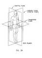
- FIG. 3Ais a schematic view showing selected anatomical planes
- FIGS. 4-9show the relevant planar surfaces in an open wedge, high tibial osteotomy conducted in accordance with the present invention
- FIGS. 10-30are schematic views showing a preferred method and apparatus for forming an appropriate osteotomy cut into the upper portion of the tibia, manipulating the tibia so as to open an appropriate wedge-like opening in the tibia, and then inserting an appropriate wedge-shaped implant into the wedge-like opening in the tibia;
- FIGS. 31-33are schematic views showing an alternative wedge-shaped implant also formed in accordance with the present invention.
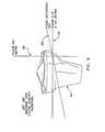
- FIG. 34is a schematic view showing a keyhole drill guide which may be used in conjunction with the wedge-shaped implant shown in FIGS. 31-33 ;
- FIG. 35is a schematic view showing another wedge-shaped implant formed in accordance with the present invention.
- FIGS. 36-38are schematic views showing still another wedge-shaped implant formed in accordance with the present invention.
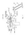
- FIGS. 39-41are schematic views showing a keyhole drill guide and an end mill which may be used in conjunction with the wedge-shaped implant shown in FIGS. 36-38 ;
- FIGS. 42-44are schematic views showing yet another wedge-shaped implant formed in accordance with the present invention.
- FIGS. 45-47are schematic views showing another wedge-shaped implant formed in accordance with the present invention.
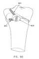
- FIGS. 48-50are schematic views showing still another wedge-shaped implant formed in accordance with the present invention.
- FIGS. 51-62are schematic views showing a novel method and apparatus for effecting a high tibial, dome osteotomy
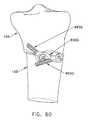
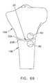
- FIGS. 63-66are schematic views showing another approach for effecting a high tibial, dome osteotomy
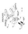
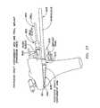
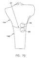
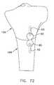
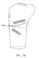
- FIGS. 67-78are schematic views showing another method and apparatus for effecting a high tibial, dome osteotomy
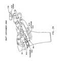
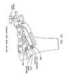
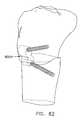
- FIGS. 79-82are schematic views showing another approach for effecting a high tibial, dome osteotomy.
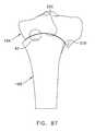
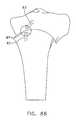
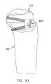
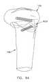
- FIGS. 83-94are schematic views showing another method and apparatus for effecting a high tibial, dome osteotomy.
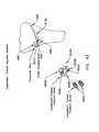
- Knee joint 5upon which an open wedge osteotomy is to be performed.
- Knee joint 5generally comprises a tibia 10 and a femur 15 .
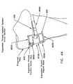
- the open wedge osteotomyis effected by first making a cut 20 ( FIG. 1 ) into the upper tibia, and then manipulating the lower portion of the tibia so as to open a wedge-like opening 25 ( FIG. 2 ) in the bone, with the wedge-like opening 25 being configured so as to adjust the manner in which load is transferred from the femur to the tibia.
- cut 20 and wedge-like opening 25may be formed in a variety of ways well known in the art.
- the present inventionprovides a new and improved method and apparatus for forming cut 20 and wedge-like opening 25 , as will be discussed in detail below.
- the bonemay be secured in position in a variety of ways well known in the art (e.g., by screwing metal plates to the bone or by inserting a wedge-shaped implant into the opening in the bone), whereby to adjust the manner in which the load is transferred from the femur to the tibia.
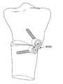
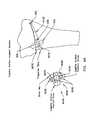
- FIG. 3shows a wedge-shaped implant 27 inserted into the wedge-like opening 25 formed in the tibia, whereby to stabilize the tibia in its reconfigured geometry.
- the present inventionalso provides a new and improved implant, and an associated method and apparatus for deploying the same at the wedge-shaped opening in the tibia, as will be discussed in detail below.
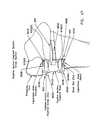
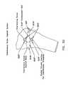
- planar surfaces of the tibiathat are relevant in performing the open wedge, high tibial osteotomy of the present invention.
- the following discussionpresents a geometric description of the planar surfaces that are relevant to the open wedge, high tibial osteotomy of the present invention.
- selected anatomical planese.g., the coronal plane, the sagittal plane and the transverse plane ( FIG. 3A ).
- the tibial plateau 30may be described as a horizontal (or transverse) plane that extends along the top surface of tibia 10 .
- the sagittal plane 32is also shown in FIG. 4 .
- tibial plateau 30is also perpendicular to the frontal (or coronal) plane 40 .
- the anterior-posterior (A-P) slopeis defined by an anterior-posterior (A-P) slope plane 45 that extends along the sloping top surface of the tibia, from anterior-to-posterior.
- A-Panterior-posterior
- Published researchhas demonstrated that the anterior-posterior (A-P) slope typically extends at an angle of approximately 7° to 11° to the tibial plateau 30 ; however, the specific angle may vary from individual to individual.
- the open wedge, high tibial osteotomy of the present inventionit is generally desirable to stay about 2 cm inferior to the A-P slope plane 45 .
- This offsetcan be referred to as the A-P offset plane 50 .
- the lateral aspect and cut depth of the cut 20may be defined by a lateral aspect plane 55 and a cut depth plane 60 , with the cut depth being about 1 cm medial to the lateral aspect of the tibia.
- the osteotomy cut plane 65(when seen from the direct frontal view of FIG. 8 ) is formed by a plane that is rotated away from the A-P offset plane 50 through an axis which is formed by the intersection of the cut depth plane 60 and the A-P offset plane 50 .
- the degree of rotationis selected so as to be sufficient to place the entry of the osteotomy cut plane 65 at the medial neck 66 ( FIG. 8 ) of the tibia.
- the A-P offset plane 50 and the osteotomy cut plane 65are “tilted” slightly from anterior to posterior (but not seen in the direct frontal view of FIG.
- axis 70which, in accordance with the present invention, defines the lateral limit of the osteotomy cut 20 .
- axis 70defines a line through the tibia which is (i) parallel to A-P slope plane 45 , and (ii) contained within osteotomy cut plane 65 .
- axis 70is used to define the lateral limit of the osteotomy cut 20 which is to be made into the tibia.
- FIG. 9is a direct view taken along the osteotomy cut plane. This view is tilted downward (e.g., at an angle of approximately 7°) from the direct frontal view of FIG. 8 . Again, the angle of tilt downward is equal to the A-P slope.
- the osteotomy cut plane 65extends parallel to the A-P slope plane 45 (in the anterior-to-posterior direction, although not in the medial-to-lateral direction), and typically slopes downward (e.g., at an angle of approximately 7-11°) when viewed in the anterior-to-posterior direction.
- the axis 70(which defines the lateral limit to the osteotomy cut 20 ) is contained within the osteotomy cut plane 65 .
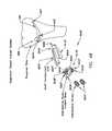
- a novel osteotomy systemwhich comprises instrumentation for use in making precise and repeatable osteotomy cuts for use in open wedge, high tibial osteotomies, preferably using an antero-medial approach.
- the novel osteotomy systemgenerally comprises a positioning guide 100 ( FIG. 16 ), a slope guide 200 ( FIG. 11 ), an apex pin 300 ( FIG. 16 ), a keyhole drill guide 400 ( FIG. 18 ), a posterior protector 500 ( FIG. 20 ), and a cutting guide 600 ( FIG. 20 ), as will hereinafter be discussed in further detail.
- the novel osteotomy systempreferably also comprises a novel opening jack 700 ( FIG. 22 ) for opening the cut 20 in the tibia so as to form the wedge-like opening 25 in the tibia, as will also hereinafter be discussed in further detail.
- the novel osteotomy systempreferably also includes a novel implant 800 ( FIG. 24 ) for positioning in the wedge-like opening in the tibia so as to stabilize the tibia in its corrected configuration, as will also hereinafter be discussed in further detail.
- a novel implant 800FIG. 24
- an implant trial base 830FIGS. 27 and 28
- implant 800it may be advantageous to use an implant trial base 830 in the course of preparing the tibia to receive implant 800 , and in order to confirm proper fit of implant 800 in its seat, as will also hereinafter be discussed in further detail.
- the surgeonfirst determines (using methods well known in the art) the degree of correction necessary to correctly re-align the weight-bearing axis of the knee; then the surgeon uses the system to make the appropriate cut 20 into the tibia; then the surgeon opens the bone cut to the extent required so as to form the desired wedge-like opening 25 in the tibia; and then the surgeon stabilizes the tibia in its corrected configuration (e.g., with the novel implant 800 ) while healing occurs.
- the novel osteotomy systemis configured so that:
- the axis of the lateral limit of the bony hinge created by the osteotomy cutlies in a plane that is perpendicular to the frontal (i.e., coronal) plane;
- the distal (i.e., lower) tibiais rotated about the bony hinge so as to substantially maintain, in anatomical alignment, the A-P slope and the frontal plane.
- novel osteotomy systemis also configured so that:
- the osteotomycan be performed less invasively.
- the osteotomycan be performed with minimum incising of soft tissue such as the medial collateral ligament, the lateral collateral ligament, and the hamstrings.
- the novel osteotomy systemis also configured so that the delicate neurological and vascular tissues at the back of the knee are fully protected during the osteotomy procedure.
- the novel osteotomy systemis constructed and used as follows.
- a vertical incisionis first made on the antero-medial portion of the knee, approximately 1 cm from the medial edge of the patellar tendon, with the incision beginning approximately 2.5-3 cm superior to the anterior tibial tubercle, and extending approximately 6-10 cm in length.
- the soft tissue between the patellar tendon and the proximal surface of the tibiais then dissected in order to make a small tunnel-like opening beneath the patellar tendon, just above the patellar tendon's insertion to the proximal tibia.
- an assemblycomprising positioning guide 100 ( FIGS. 10 and 16 ), slope guide 200 ( FIGS. 10 and 11 ) and an introducer 105 ( FIGS. 10 and 11 ) is advanced to the surgical site.
- the assembly of positioning guide 100 , slope guide 200 and introducer 105is pre-assembled prior to opening the skin.
- This assemblyis assembled by first mounting slope guide 200 to positioning guide 100 , and then mounting introducer 105 to both slope guide 200 and positioning guide 100 by using a screw 115 ( FIG. 10 ) which passes through slope guide 200 and is received in a threaded bore 120 ( FIG. 16 ) formed in positioning guide 100 .
- slope guide 200may comprise two separate elements which are secured together, e.g., a base 210 and a guide element 215 which are connected together by pins 205 , with base 210 being formed out of a radio-translucent material (e.g., plastic) and guide element 215 being formed out of a radio-opaque material (e.g., stainless steel), whereby guide element 215 will be visible under fluoroscopy and base 210 will be effectively invisible under fluoroscopy, as will hereinafter be discussed.
- a radio-translucent materiale.g., plastic
- guide element 215being formed out of a radio-opaque material (e.g., stainless steel)
- introducer 105may comprise an arm 125 and a handle 130 .
- Arm 125 and handle 130may be formed as two separate elements secured together, or arm 125 and handle 130 may be formed as a singular construction.
- the foregoing assembly(of positioning guide 100 , slope guide 200 and introducer 105 ) is maneuvered so that a tibial tubercle locating tab 135 ( FIGS. 10 and 16 ) of positioning guide 100 is inserted between the patellar tendon (not shown) and the tibia, and so that tibial tubercle locating tab 135 is set against the superior margin of the tibial tubercle.
- the tibial tubercleprovides a rough alignment guide for aligning positioning guide 100 with the tibia.
- the underside of tibial tubercle locating tab 135may include serrations, ridges, ribs, etc. ( FIG. 11E ) so as to facilitate stabilization of tibial tubercle locating tab 135 (and hence the instrumentation) against the tibia.
- the assemblyis then aligned so that the underside surface 220 ( FIG. 11 ) of guide element 215 of slope guide 200 is aligned with the top of the medial condyle 75 of the tibia.
- the top edge 225 of guide element 215 of slope guide 200can be aligned with medial condyle 75 , thereby offsetting the osteotomy by a fixed distance distally (e.g., 3 mm).
- guide element 215 of slope guide 200By forming the guide element 215 of slope guide 200 out of a radio-opaque material and by forming the base 210 of slope guide 200 out of a radio-translucent material, base 210 will be effectively invisible under fluoroscopy and guide element 215 will stand out in clear relief against the bone.
- guide element 215 of slope guide 200is preferably formed with a “Z shape,” ( FIGS. 10 and 11A ) so as to provide additional functionality. More particularly, by forming guide element 215 with a “Z shape”, several significant advantages are obtained. First, this construction permits guide element 215 to wrap around the perimeter of the tibia. Second, the “Z shape” of guide element 215 also operates to indicate if the slope guide is not vertically aligned with the level of the fluoroscope. More particularly, if slope guide 200 is not vertically aligned with the level of the fluoroscope, the “Z shape” of guide element 215 will appear as a jagged or zig-zag shape on the fluoroscope ( FIG. 11B ).
- guide element 215is vertically aligned with the level of the fluoroscope, then the guide element will appear as a straight line on the fluoroscope ( FIGS. 11 and 11C ).
- This vertical alignmentis important, since it enables alignment of slope guide 200 (and hence positioning guide 100 ) with the medial condyle, i.e., with the A-P slope plane.
- guide element 215 of slope guide 200with an “L shape” configuration, rather than the “Z shape” configuration discussed above. Again, this construction provides several benefits.
- the “L shape” configurationpermits guide element 215 to wrap around the perimeter of the tibia.
- the “L shape” of guide element 215also operates to indicate if the slope guide is not vertically aligned with the level of the fluoroscope. More particularly, if slope guide 200 is not vertically aligned with the level of the fluoroscope, the “L shape” of guide element 215 will appear as an “L shape” on the fluoroscope.
- guide element 215is vertically aligned with the level of the fluoroscope, then the guide element will appear as a straight line on the fluoroscope. Again, this vertical alignment is important, since it enables alignment of slope guide 200 (and hence positioning guide 100 ) with the medial condyle, i.e., with the A-P slope plane.
- the assemblyis then maneuvered so that the medial locating pin 140 ( FIGS. 10 , 11 and 16 ), preferably formed as a pin although it could also be formed as a tab, fin, etc., is located against the medial aspect 80 ( FIG. 16 ) of the tibia.
- medial locating pin 140is held in contact with the medial aspect of the tibia, thereby ensuring proper alignment of the instrumentation.
- Medial locating pin 140references the medial aspect of the tibia, thus setting the distance from the medial aspect of the tibia to the apex pin 300 ( FIG.
- this reference distanceis used in conjunction with the sizing of the osteotomy implant 27 ( FIG. 3 ) so as to ensure a proper tibial reconstruction, e.g., the distance from the medial aspect of the tibia to the center of apex pin 300 may correspond to the distance from the medial aspect of the wedge-shaped osteotomy implant 27 to the vertex of the wedge angle of the implant.
- the reference distancemay be the distance from the medial aspect of the tibia to a neutral axis of rotation in the bony hinge, which could be estimated by calculation.
- the distance from the medial aspect of the tibia to the neutral axis of the bony hingemay correspond to the distance from the medial aspect of the implant to the vertex of the wedge angle of the implant.
- slope guide 200is provided with a ball 230 and a groove 235 ( FIGS. 10 and 11 ).
- the fluoroscopearranged so that it is set in the lateral mode, with the image being taken from the medial side at the level of the tibial plateau (see FIG. 11 ).
- the assemblyis maneuvered until ball 230 is centered in groove 235 ( FIG. 11 ).
- the systemis aligned with the sagittal plane (i.e., positioning guide 100 is disposed so that apex pin 300 will extend perpendicular to the frontal plane, as will hereinafter be discussed).
- slope guide 200when slope guide 200 is aligned with the medial condyle 75 , and when ball 230 is aligned with groove 235 , the system is aligned with (i) the A-P slope, and (ii) the sagittal plane.
- slope guide 200when slope guide 200 is aligned with medial condyle 75 , and when ball 230 is aligned with groove 235 , the instrumentation is positioned so that apex pin 300 (see below) is aligned with both the A-P slope and the sagittal plane, as will hereinafter be discussed.
- apex pin 300is inserted through positioning guide 100 and into the tibia.
- An apex aimer 155( FIGS. 14 and 16 ) serves to guide apex pin 300 into the tibia with the proper orientation, i.e., so that apex pin 300 is positioned along the axis 70 ( FIG. 8 ) which is located at the lateral limit of the intended osteotomy cut, with apex pin 300 extending parallel to the A-P slope and perpendicular to the coronal plane, and with apex pin 300 being coplanar with the intended cutting plane 65 .
- apex pin 300can serve as the lateral stop for the osteotomy saw, whereby to clearly define the perimeter of the bony hinge, as will hereinafter be discussed.
- Apex pin 300may be tapped or drilled into virgin bone, or it may be received in a pre-drilled hole (e.g., formed using apex aimer 155 and a standard surgical drill).
- a thumbscrew 160FIG. 16 ) may be used to secure apex pin 300 to positioning guide 100 .
- Apex pin 300may be generally cylindrical in shape and, if desired, apex pin 300 may be provided with a rounded, or “bullet-shaped”, nose 303 ( FIG. 11G ), or other tapered end configuration, so as to facilitate deployment into the tibia.
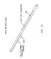
- apex pin 300may have a flat 305 ( FIGS. 12 and 13 ) formed thereon to promote a complete cut-through of the osteotomy.
- apex pin 300is provided with a distinct flat 305
- itis preferably provided with a counterpart flat 310 ( FIGS. 12 and 13 ), such that when apex pin 300 is positioned within the tibia and thumbscrew 160 is tightened against flat 310 , the aforementioned flat 305 will be aligned with the osteotomy cut, whereby to ensure that the osteotomy blade cuts completely through the bone to reach the apex pin. See FIG. 13 .
- the flats 305 , 310may be diametrically opposed to one another, with thumbscrew 160 also being aligned with the osteotomy cut, whereby to make insertion of apex pin 300 less prone to error.
- apex pin 300may be necked down to a smaller diameter in the area of the osteotomy.
- a slight relief areaexists to accommodate the saw blade so as to help promote a complete cut-through, but does not require any specific orientation of the apex pin with respect to the osteotomy plane, as is the case where the apex pin is formed with distinct flats.
- apex aimer 155may be used with a guide sleeve 161 ( FIG. 14 ) and a small-diameter guide pin 165 in order to first check the position of the small-diameter guide pin 165 relative to the desired axis for the apex pin, before thereafter deploying the larger-diameter apex pin 300 .
- re-positioning a misdirected small-diameter guide pin 165is easier and less traumatic to the host bone than re-positioning a misdirected larger-diameter apex pin 300 .
- tibial tubercle locating tab 135is preferably sized so that it also functions as an anterior protector, by providing a protective shield between the oscillating saw blade (to be used later in the procedure to form the osteotomy cut 20 ) and the anterior soft tissue structures, e.g., the patellar tendon.
- the tibial tubercle locating tab 135is intended to be positioned between the face of tibia 10 and the backside of the patellar tendon.
- tibial tubercle locating tab 135also functions as a patellar tendon protector.
- apex pin 300is positioned in the patient's tibia so that the apex pin extends (i) parallel to the A-P slope of the tibia, and (ii) parallel to the sagittal plane of the patient.
- the osteotomy cut 20is subsequently formed in the bone (see below) by cutting along the osteotomy cut plane 65 ( FIG. 8 ) until the apex pin is engaged by the bone saw, so that the perimeter of the bony hinge is defined by the location of the apex pin, the bony hinge will extend (i) parallel to the A-P slope of the tibia, and (ii) parallel to the sagittal plane of the patient.
- the final configuration of the tibiacan be properly regulated when the bone cut is thereafter opened so as to form the open wedge osteotomy.
- slope guide 200 and introducer 105are removed ( FIG. 16 ), leaving positioning guide 100 properly aligned on, and secured to, the tibia, with apex pin 300 extending parallel to the A-P slope and parallel to the sagittal plane of the patient.
- the system of FIGS. 10-30utilizes a wedge-shaped implant to maintain the open wedge osteotomy.
- the size of positioning guide 100 and the associated instrumentationare preferably used to prepare the osteotomy to fit a particular implant sizing of small, medium or large.
- the medial locating pin 140 , the size of positioning guide 100 , and apex pin 300all preferably combine to implement an implant sizing scheme of small, medium or large.
- medial locating pin 140 , positioning guide 100 and apex pin 300combine to provide a known, fixed distance from the medial aspect of the tibia to the apex pin.
- the size of the planned osteotomyis then set, allowing a specifically-sized implant (e.g., small, medium or large) to nominally fit between the medial aspect of the tibia and the apex pin.
- medial locating pin 140is substantially aligned with the entry point of the planned osteotomy.
- keyhole drill guide 400is then attached to positioning guide 100 by passing keyhole drill guide 400 over frontal pin 145 and apex aimer 155 . Keyhole drill guide 400 is then secured in this position with thumbscrew 405 . At this point, a distal pin 410 is inserted through keyhole drill guide 400 and into the tibia. Distal pin 410 further secures the instrumentation to the tibia. Next, a surface locator pin 415 is inserted through keyhole drill guide 400 . Surface locator pin 415 slides through keyhole drill guide 400 until the distal tip of surface locator pin 415 contacts the surface of the tibia.
- this surfacemay be referred to as the “antero-medial surface” or the “A-M surface”, which is the anatomical surface of the tibia corresponding to the antero-medial approach of the osteotomy.
- A-M surfaceis the anatomical surface of the tibia corresponding to the antero-medial approach of the osteotomy.
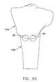
- an end mill 420is inserted into the distal hole 425 (i.e., the bottom hole 425 ) of keyhole drill guide 400 and drilled until a stop flange 430 on end mill 420 contacts the proximal end of surface locator pin 415 , whereby to form the distal keyhole 85 ( FIG. 21 ) in the tibia.
- the drilling procedureis then repeated for the proximal hole 435 (i.e., the top hole 435 ), whereby to form the proximal keyhole 90 ( FIG. 21 ) in the tibia.
- keyholes 85 and 90are formed so that one keyhole (i.e., proximal keyhole 90 ) sits above the other keyhole (i.e., distal keyhole 85 ), in a so-called “over-under” configuration. While it is possible to drill the proximal keyhole before the distal keyhole, it is generally preferable to drill the distal keyhole first. This is because drilling the distal keyhole before the proximal keyhole reduces the possibility that the sloping nature of the bone will cause a later-drilled keyhole to slip into an earlier-drilled keyhole. It should be appreciated that keyhole drill guide 400 is configured so that distal hole 425 and proximal hole 435 will overlap the osteotomy cutting plane 65 to some extent ( FIG.
- end mill 420is removed, thumbscrew 405 is loosened, and then keyhole drill guide 400 is removed.
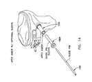
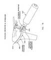
- posterior protector 500is attached to an introducer 505 with a thumbscrew 510 .
- Posterior protector 500preferably comprises a far tip 515 and a curved portion 520 .
- Far tip 515is preferably formed out of a flexible material so as to facilitate passage of the posterior protector along the surface of the posterior cortex and beneath overlying soft tissue.
- Curved portion 520comprises a relatively stiff material which provides support for far tip 515 .
- Far tip 515 of posterior protector 500is inserted into the incision and worked along the posterior cortex of the tibia until far tip 515 of posterior protector 500 substantially crosses the axis of, and in some cases actually engages, apex pin 300 ( FIG. 21 ).
- posterior protector 500Once posterior protector 500 has been properly positioned, the thumbscrew 510 is unscrewed, and introducer handle 505 is removed, leaving posterior protector 500 extending along the posterior cortex of the tibia, interposed between the tibia and the delicate neurological and vascular structures located at the back of the knee.
- Cutting guide 600is then attached to positioning guide 100 and secured in place using cutting guide thumbscrew 605 .
- Cutting guide 600comprises alignment rods 610 ( FIG. 21 ) that extend from the cutting guide into the pre-drilled keyholes 85 , 90 ( FIG. 21 ) to assist with cutting alignment. More particularly, alignment rods 610 ensure proper alignment between cutting guide 600 , its cutting slot 615 ( FIGS. 20 and 21 ) and the pre-drilled keyholes 85 , 90 previously formed in the tibia with end mill 420 and, ultimately, ensure the desired fit between the implant and the tibia.
- posterior protector 500is attached to cutting guide 600 using thumbscrew 620 ( FIG. 20 ).
- the instrumentationis ready to form the osteotomy cut, with cutting slot 615 of cutting guide 600 properly aligned with the osteotomy cut plane, apex pin 300 properly positioned at the far (lateral) limit of the osteotomy cut, tibial tubercle locating tab 135 forming a protective shield for the patellar tendon, and with posterior protector 500 forming a protective shield for the vascular and neurological structures at the back of the knee.
- cutting guide 600is sized and shaped, and cutting slot 615 is positioned, so that, in addition to being aligned with the apex pin 300 , the entry point of the cutting plane into the tibia is located at an appropriate location on the tibia's medial neck 66 .
- a saw blade 625(attached to an oscillating saw, not shown) is inserted into cutting slot 615 of cutting guide 600 .
- the osteotomy cutis then made by plunging the oscillating saw blade through cutting slot 615 and into the bone ( FIG. 20 ).
- the saw bladeis used to cut completely through the medial and posterior cortices.
- the sawis operated until saw blade 625 contacts posterior protector 500 and apex pin 300 .
- As the saw blade cuts through the tibiait is constrained by cutting slot 615 , apex pin 300 and posterior protector 500 , so that the saw blade may only cut bone along the osteotomy plane, up to (but not beyond) the desired location of the bony hinge, and does not cut soft tissue.
- tibial tubercle locating tab 135also ensures that the saw blade will not inadvertently cut the patellar tendon.
- cutting slot 615 , apex pin 300 , posterior protector 500 and tibial tubercle locating tab 135effectively define a “safe cutting zone” for saw blade 625 .
- saw blade 625forms the desired osteotomy cut 20 along the cutting plane
- the saw bladeis removed, and a hand osteotome (not shown) of the sort well know in the art is inserted through cutting slot 615 and into the osteotomy cut 20 , and then the cut is completed through the posterior cortical bone near apex pin 300 and posterior protector 500 . Then the hand osteotome is removed.
- a hand osteotome(not shown) of the sort well know in the art is inserted through cutting slot 615 and into the osteotomy cut 20 , and then the cut is completed through the posterior cortical bone near apex pin 300 and posterior protector 500 . Then the hand osteotome is removed.
- the osteotomy cut 20has been completed, with the osteotomy cut terminating on the lateral side at apex pin 300 , so that the bony hinge is properly positioned at the desired location, i.e., parallel to the A-P slope and perpendicular to the coronal plane.
- thumbscrew 620is loosened and posterior protector 500 removed. Then thumbscrew 605 is loosened and cutting guide 600 is removed. See FIG. 21 .
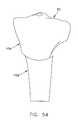
- the desired osteotomy cut 20has been formed in the tibia, with keyholes 85 and 90 formed below and above, respectively, the osteotomy cut.
- the boneIn order to complete the procedure, the bone must now be opened so as to reconfigure the tibia to the desired geometry, and then the tibia stabilized with the desired configuration, e.g., by inserting a wedge-shaped implant 27 into wedge-like opening 25 .
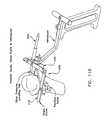
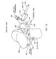
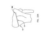
- opening jack 700is assembled onto the instrumentation by receiving frontal pin 145 in a hole 705 formed in jack arm 710 , by receiving apex aimer 155 in another hole 715 formed in jack arm 710 and jack arm 725 , and by receiving distal pin 410 in a slot 720 formed in jack arm 725 . Opening jack 700 is secured to positioning guide 100 with a thumbscrew 730 .
- the jackis opened by rotating jack screw 735 .
- Thiscauses jack arm 725 to pivot about apex aimer 155 so as to open the jack and thereby open the desired wedge-like opening 25 in the tibia. See FIG. 23 .
- the patient's lower legis manipulated as jack screw 735 is turned so as to assist in opening of the bone about the bony hinge.
- the tibiawill be reoriented in a highly controlled manner, due to the fact that the bony hinge is precisely positioned at axis 70 through the use of apex pin 300 , i.e., the bony hinge extends parallel to the A-P slope and parallel to the sagittal plane. Furthermore, as the wedge-like opening 25 is created in the bone, the risk of bone cracking is minimized, due to the fact that apex pin 300 forms an oversized hole 95 ( FIGS. 23A and 27 ) at the lateral end of the bone cut, i.e., “oversized” relative to the thickness of the osteotomy cut, whereby to reduce the occurrence of stress risers and the like as the bone is opened.
- the surgeonuses opening jack 700 to open the bone to the extent necessary to correctly re-align the weight-bearing axis of the knee.
- an implantis positioned at the wedge-like opening 25 so as to hold the re-oriented bone with the desired orientation.
- the implantmay be a “generic” wedge-shaped implant such as the implant 27 shown in FIG. 3 .
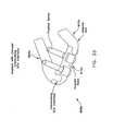
- Wedge-shaped implant 800is characterized by a wedge-like side profile configured to match the geometry of the wedge-like opening 25 (i.e., to match the prescribed correction angle of the open wedge, high tibial osteotomy).
- wedge-shaped implant 800is also formed so as to have a U-shaped top profile, such that it can form a barrier about the perimeter of the wedge-like opening 25 , with the open end of the U-shaped implant positioned against the bony hinge, whereby to contain graft material (e.g., bone paste, bone cement, etc.) which may be positioned within the interior of the wedge-like opening 25 .
- graft materiale.g., bone paste, bone cement, etc.
- wedge-shaped implant 800is formed so as to have an asymmetric configuration when viewed in a top view, so as to mate with the geometry of the tibia when the implant is positioned using an antero-medial approach.
- Wedge-shaped implant 800is sized so as to match the known distance from the medial aspect of the tibia to the axis 70 of the bony hinge, which is set by the position of apex pin 300 .
- Wedge-shaped implant 800may be formed out of absorbable material or non-absorbable material, as desired.
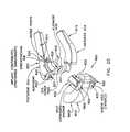
- implant 800preferably comprises a three-part assembly, comprising posterior graft containment arm (GCA) 805 , a base 810 and an anterior graft containment arm (GCA) 815 .
- the individual components of implant 800may each be formed out of absorbable material and/or non-absorbable material, as desired. Furthermore, where one or more of the implant components is formed out of an absorbable material, the absorption characteristics of the material may vary as desired.
- base 810may be formed out of a relatively slowly-absorbing material, while posterior graft containment arm (GCA) 805 and anterior graft containment arm (GCA) 815 may be formed out of a relatively faster-absorbing material.
- Base 810preferably comprises a pair of keys 820 , 825 .
- Keys 820 , 825have a disposition which is complementary to the disposition of the keyholes 85 , 90 , i.e., where keyholes 85 , 90 have an “over-under” configuration, keys 820 , 825 also have an “over-under” configuration, as will hereinafter be discussed in further detail.
- implant 800is formed so that posterior graft containment arm (GCA) 805 has a generally wedge-shaped profile including an engagement seat 826 comprising an alignment post 827 , and an introducer hole 828 opening on the antero-medial side of the component for engagement with introducer 845 (see below).
- a strengthening rib 829is preferably provided as shown.
- raised points or dimples 831may be provided to help fix posterior graft containment arm (GCA) 805 to the bone.
- An alignment tab 832is provided for extension into upper keyhole 90 ( FIG. 29 ) when posterior graft containment arm (GCA) 805 is positioned in the wedge-shaped opening 25 .
- base 805is formed so that its keys 820 , 825 each includes a bore 833 , 834 , respectively, with the keys being slotted longitudinally so as to permit expansion of the keys when screws 865 are thereafter deployed in the bores, whereby to help lock the implant against the hard cortical bone of the tibia.
- External ribs 836may be provided on the outer surfaces of keys 820 , 825 so as to help fix keys 820 , 825 in keyholes 85 , 90 , respectively, when keys 820 , 825 are expanded, as will hereafter be discussed in further detail. External ribs 836 may extend longitudinally ( FIG. 25 ) or circumferentially (not shown).
- Keys 820 , 825protrude from the upper and lower surfaces of base implant 810 , and accommodate shear loads which may be imposed across the implant. Furthermore, expansion of keys 820 , 825 creates an interference fit with the cortical bone of the tibia, and can help support tensile loads which may be imposed across the implant.
- An alignment mechanisme.g., a bore (not shown), is provided for mating with alignment post 827 of posterior graft containment arm (GCA) 805 .
- GCAposterior graft containment arm
- the bores 833 , 834may be axially aligned with the longitudinal axes of keys 820 , 825 , respectively.
- the bores 833 , 834may be arranged so that they diverge from one another, downwardly and upwardly, respectively, so as to direct screws 865 deeper into the adjacent portions of the tibia.
- Anterior graft containment arm (GCA) 815also comprises a generally wedge-shaped profile, and an alignment tab 837 is provided for extension into lower keyhole 85 when GCA 815 is positioned in the wedge-shaped opening 25 .
- Implant 800is preferably assembled in situ.
- an implant trial base 830( FIGS. 27 and 28 ) in the course of preparing the tibia to receive implant 800 , and in order to confirm proper fit of implant 800 in its seat.
- a pre-assembled assemblycomprising posterior graft containment arm (GCA) 805 , an implant trial base 830 and two guide sleeves 835 , 840 are first inserted into wedge-like opening 25 in the bone using an introducer 845 . See FIGS. 27 and 28 .
- GCAposterior graft containment arm
- a drill sleeve 850 and a drill 855are inserted into guide sleeve 840 ( FIG. 27 ).
- An upper holeis drilled into the tibia with the drill.
- the drilling procedureis then repeated for guide sleeve 835 so as to create a lower hole.
- drill sleeve 850 and drill 855are removed from the surgical site.
- a tap 860is inserted into guide sleeve 840 and the upper hole is tapped. See FIG. 28 .
- the tapis inserted into guide sleeve 835 and the lower hole is tapped.
- tap 860is removed from the surgical site.
- posterior graft containment arm (GCA) 805is released from introducer 845 , and then introducer 845 and implant trial base 830 are removed.
- Posterior graft containment arm (GCA) 805remains in wedge-like opening 25 .
- anterior graft containment arm (GCA) 815is placed into the osteotomy opening and aligned with the prepared implant holes. See FIG. 29 . If necessary, jack screw 735 is rotated as needed so as to facilitate insertion of anterior GCA 815 . At this point in the procedure, posterior graft containment arm (GCA) 805 and anterior graft containment arm (GCA) 815 are positioned in wedge-like opening 25 .
- implant base 810is inserted into the prepared osteotomy, with keys 820 and 825 seated in tibial holes 85 and 90 , respectively, and with base 810 capturing posterior graft containment arm (GCA) 805 and anterior graft containment arm (GCA) 815 against the bony hinge.
- GCAposterior graft containment arm
- GCAanterior graft containment arm
- Keys 820 and 825 , seating in keyholes 85 and 90help ensure a precise fit of the implant to the bone.
- jack screw 735is adjusted as necessary so as to facilitate insertion of the base into the osteotomy.
- jack screw 735is tightened slightly so as to ensure that the implant components are fully seated into the osteotomy wedge, with at least implant base 810 , and preferably also posterior graft containment arm (GCA) 805 and anterior graft containment arm (GCA) 815 , providing load bearing support to the tibia.
- fixation screws 865are inserted through keys 820 and 825 in base 810 and into the tapped holes in the tibia, and then tightened into place. As this occurs, fixation screws 865 expand keys 820 , 825 within keyholes 85 , 90 so as to lock keys 820 , 825 to the adjacent cortical bone, and fixation screws 865 extend into the tibia, so as to further lock the implant in position. See FIG. 30 .
- opening jack 700 , positioning guide 100 , apex pin 300 , distal pin 410 , frontal pin 145 and A-M pin 150are removed from the surgical site, and the incision closed.
- implant 800with two graft containment arms, e.g., posterior graft containment arm (GCA) 805 and anterior graft containment arm (GCA) 815 , is frequently preferred. However, in some circumstances, it may be desirable to omit one or both of posterior graft containment arm (GCA) 805 and anterior graft containment arm (GCA) 815 . Thus, in one preferred form of the invention, implant 800 comprises only base 810 and omits both posterior graft containment arm (GCA) 805 and anterior graft containment arm (GCA) 815 .
- GCAposterior graft containment arm
- GCAanterior graft containment arm
- Providing implant 800 with a pair of keys 820 , 825is generally preferred. However, in some circumstances, it may be desirable to omit one or the other, or both, of keys 820 , 825 . Furthermore, in other circumstances, it may be desirable to provide more than two keys, e.g., to provide three keys.
- each of the keys 820 , 825may include more than one bore 833 , 834 .
- a keymay include two bores, one angled leftwardly so as to direct a fixation screw leftwardly into the tibia to the left of the key, and/or one angled rightwardly so as to direct a fixation screw rightwardly into the tibia to the right of the key.
- apex pin 300is significant for a number of reasons:
- the seat for the implantis always of known size, thereby simplifying proper fitting of the implant to its seat in the bone, and also reducing the inventory of different-sized implants which must be on hand during the surgery;
- bone resecting toolscan be used with increased confidence, without fear of inadvertently cutting into, or even through, the bony hinge;
- the implantcan be reliably manufactured to appropriately address the required degree of correction needed to effect knee realignment (e.g., a 4 degree implant slope will always provide a 4 degree angle of correction).
- apex pin 300posterior protector 500 and tibial tubercle locating tab 135 creates a “protection zone”
- cutting guide 600creates a closely constrained cutting path for saw blade 625 , thereby together ensuring that only the desired portion of the bone is cut.
- posterior protector 500ensures that the delicate neurological and vascular tissues at the back of the knee are protected during cutting of the tibia.
- keyholes 85 , 90 in the tibiaand the provision of keys 820 , 825 in the implant, is significant inasmuch as they provide improved stabilization of the implant, particularly against rotational and shearing forces. This is particularly true inasmuch as keyholes 85 , 90 extend through the hard cortical bone at the periphery of the tibia.
- Implant 800 Aalso formed in accordance with the present invention.
- Implant 800 Ais generally similar to the implant 800 disclosed above, except that implant 800 A has its keys disposed in a “side-by-side” configuration, rather than the “over-under” key configuration of implant 800 , as will hereinafter be discussed in further detail.
- implant 800 Aalso provides an alternative approach for joining the posterior graft containment arm (GCA) to the base, and an alternative approach for joining the anterior graft containment arm (GCA) to the base, as will hereinafter also be discussed in further detail.
- GCAposterior graft containment arm
- GCAanterior graft containment arm
- implant 800 Acomprises a posterior graft containment arm (GCA) 805 A, a base 810 A and an anterior graft containment arm (GCA) 815 A.
- Base 810 Apreferably comprises a pair of keys 820 A, 825 A. Keys 820 A, 825 A are laterally displaced along the width of base 810 A, in a “side-by-side” configuration. This is in contrast to the construction of implant 800 , which uses an “over-under” configuration for its keys 820 , 825 ( FIG. 24 ).
- the “side-by-side” configurationprovides, at the base of the implant, excellent load-bearing characteristics and substantial resistance to rotational and shear forces.
- Posterior graft containment arm (GCA) 805 Aincludes a tab 870 A, and base 810 A includes a groove 873 A, whereby posterior graft containment arm (GCA) 805 A can mate with base 810 A.
- a screw 875 Ais used to secure tab 870 A in groove 873 A, and hence posterior graft containment arm (GCA) 805 to base 810 .
- Anterior graft containment arm (GCA) 815 Aincludes a flange 878 A, and implant base 810 A includes a recess 881 A, whereby anterior graft containment arm (GCA) 815 A can mate with base 810 A.
- Another screw 875 Ais used to secure flange 878 A in recess 881 A, and hence anterior graft containment arm (GCA) 815 to base 810 .
- Posterior graft containment arm (GCA) 805 A, and/or anterior graft containment arm (GCA) 815 Amay include raised points or dimples 831 A.
- Keys 820 A, 825 Aeach include a bore 833 A, 834 A, respectively. Bores 833 A, 834 A receive fixation screws 865 A for fixing implant 800 A to the tibia. Bores 833 A, 834 A preferably diverge from the longitudinal axes of keys 820 A, 825 A, respectively, so as to direct fixation screws 865 A downwardly or upwardly into the adjacent portions of the tibia. Keys 820 A, 825 A may also include external ribs 836 A. External ribs 836 A may extend longitudinally (not shown) or circumferentially ( FIG. 32 ).
- Keys 820 A, 825 Amay also be slotted (i.e., in a manner analogous to the slots provided in keys 820 , 825 of implant 800 ), whereby to permit keys 820 A, 825 A to expand when fixation screws 865 A are received in bores 833 A, 834 A.
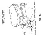
- a keyhole drill guide 400 A(also sometimes referred to as a “keystone drill template”) may be used ( FIG. 34 ).
- Keyhole drill guide 400 Ais generally similar to the keyhole drill guide 400 disclosed above, except that keyhole drill guide 400 A has its two guide holes 425 A, 435 A disposed in a “side-by-side” disposition, rather than the “over-under” disposition of the two guide holes 425 , 435 of drill guide 400 .
- Implant 800 A(and drill guide 400 A) may be used in an open wedge, high tibial osteotomy in a manner which is generally similar to that previously described with respect to implant 800 (and drill guide 400 ).
- implant 800 Awith two graft containment arms, e.g., posterior graft containment arm (GCA) 805 A and anterior graft containment arm (GCA) 815 A, is frequently preferred. However, in some circumstances, it may be desirable to omit one or both of posterior graft containment arm (GCA) 805 A and anterior graft containment arm (GCA) 815 A. Thus, in one preferred form of the invention, implant 800 A comprises only base 810 A and omits both posterior graft containment arm (GCA) 805 A and anterior graft containment arm (GCA) 815 A.
- GCAposterior graft containment arm
- GCAanterior graft containment arm
- Providing implant 800 A with a pair of keys 820 A, 825 Ais generally preferred. However, in some circumstances, it may be desirable to omit one or the other, or both, of keys 820 A, 825 A. Furthermore, in other circumstances, it may be desirable to provide more than two keys, e.g., to provide three keys.
- each of the keys 820 A, 825 Amay include more than one bore 833 A, 834 A.
- a keymay include two bores, one angled upwardly so as to direct a fixation screw upwardly into the tibia above the key, and/or one angled downwardly so as to direct a fixation screw downwardly into the tibia below the key.
- Implant 800 Bis generally similar to the implant 800 A disclosed above, except that implant 800 B provides an alternative approach for joining the anterior graft containment arm (GCA) to the implant base, among other things.
- GCAanterior graft containment arm
- implant 800 Bcomprises a posterior graft containment arm (GCA) 805 B, a base 810 B and an anterior graft containment arm (GCA) 815 B.
- Base 810 Bpreferably comprises a pair of keys 820 B, 825 B. Keys 820 B, 825 B are laterally displaced along the width of base 810 B, in a “side-by-side” configuration. Again, this is in contrast to the construction of implant 800 , which uses an “over-under” configuration for its keys 820 , 825 ( FIG. 24 ).
- Posterior graft containment arm (GCA) 805 Bincludes a tab 870 B, and base 810 B includes a groove 873 B, whereby posterior graft containment arm (GCA) 805 B can mate with base 810 B.
- Anterior graft containment arm (GCA) 815 Aincludes a slide face 883 B, and implant base 810 B includes an opposing slide face 885 B, whereby anterior graft containment arm (GCA) 815 B can mate with base 810 B.
- a bridge-type fastener 888 Bis used to secure anterior graft containment arm (GCA) 815 B in position, with arm slide face 883 B engaging base slide face 885 B, after the implant is positioned within positioned within the wedge-like opening 25 .
- GCAanterior graft containment arm
- Posterior graft containment arm (GCA) 805 B, and/or anterior graft containment arm (GCA) 815 B,may include raised points or dimples 831 B.
- Keys 820 B, 825 Beach include a bore 833 B, 834 B, respectively. Bores 833 B, 834 B receive fixation screws 865 B for fixing implant 800 B to the tibia. Bores 833 B, 834 B preferably diverge from the longitudinal axes of keys 820 B, 825 B, respectively, so as to direct fixation screws 865 B downwardly or upwardly into the adjacent portions of the tibia. Keys 820 B, 825 B may also include external ribs 836 B. External ribs 836 B may extend longitudinally or circumferentially.
- Keys 820 B, 825 Bmay also be slotted (i.e., in a manner analogous to the slots provided in keys 820 , 825 of implant 800 ), whereby to permit keys 820 B, 825 B to expand when fixation screws 865 B are received in bores 833 B, 834 B.
- Implant 800 Bmay be used in an open wedge, high tibial osteotomy in a manner which is generally similar to that previously described with respect to implant 800 .
- implant 800 Bwith two graft containment arms, e.g., posterior graft containment arm (GCA) 805 B and anterior graft containment arm (GCA) 815 B, is frequently preferred. However, in some circumstances, it may be desirable to omit one or both of posterior graft containment arm (GCA) 805 B and anterior graft containment arm (GCA) 815 B. Thus, in one preferred form of the invention, implant 800 B comprises only base 810 B and omits both posterior graft containment arm (GCA) 805 B and anterior graft containment arm (GCA) 815 B.
- GCAposterior graft containment arm
- GCAanterior graft containment arm
- Providing implant 800 B with a pair of keys 820 B, 825 Bis generally preferred. However, in some circumstances, it may be desirable to omit one or the other, or both, of keys 820 B, 825 B. Furthermore, in other circumstances, it may be desirable to provide more than two keys, e.g., to provide three keys.
- each of the keys 820 B, 825 Bmay include more than one bore 833 B, 834 B.
- a keymay include two bores, one angled upwardly so as to direct a fixation screw upwardly into the tibia above the key, and/or one angled downwardly so as to direct a fixation screw downwardly into the tibia below the key.
- Implant 800 Cis generally similar to the implant 800 disclosed above, except that implant 800 C has a shear rib 890 C on its base, laterally displaced from the two keys (which are themselves arranged in an “over-under” configuration), as will hereinafter be discussed in further detail. Furthermore, implant 800 C also provides an alternative approach for joining the posterior graft containment arm (GCA) to the base, and an alternative approach for joining the anterior graft containment arm (GCA) to the base, as will hereinafter also be discussed in further detail.
- GCAposterior graft containment arm
- GCAanterior graft containment arm
- implant 800 Calso provides a means for joining the distal end of posterior graft containment arm (GCA) 805 C to the distal end of anterior graft containment arm (GCA) 815 C, as will hereinafter also be discussed in further detail.
- GCAposterior graft containment arm
- GCAanterior graft containment arm
- implant 800 Ccomprises a posterior graft containment arm (GCA) 805 C, a base 810 C and an anterior graft containment arm (GCA) 815 C.
- a bridge 892 Cconnects the distal end of posterior graft containment arm (GCA) 805 C with the distal end of anterior graft containment arm (GCA) 815 C.
- bridge 892 Cmay be provided with a distal tab 898 C to be received in oversized hole 95 C.
- Distal tab 898 Cserves to improve the alignment and stability of implant 800 C when seated in wedge-like opening 25 C.
- a shear rib 890 Cis formed in base 810 C, laterally displaced from the two keys 820 C, 825 C, which are arranged in an “over-under” configuration.
- Posterior graft containment arm (GCA) 805 Cincludes a recess 893 C, and base 810 C includes a shoulder 894 C, whereby posterior graft containment arm (GCA) 805 C can mate with base 810 C.
- Anterior graft containment arm (GCA) 815 Cincludes a recess 895 C, and implant base 810 C includes a shoulder 896 C, whereby anterior graft containment arm (GCA) 815 C can mate with base 810 C.
- Posterior graft containment arm (GCA) 805 C, and/or anterior graft containment arm (GCA) 815 C,may include raised points or dimples 831 C.
- Keys 820 C, 825 Ceach include a bore 833 C, 834 C, respectively. Bores 833 C, 834 C receive fixation screws 865 C for fixing implant 800 C to the tibia.
- the bores 833 C, 834 Cmay be axially aligned with the longitudinal axes of keys 820 C, 825 C, respectively. Alternatively, the bores 833 C, 834 C may be arranged so that they diverge from one another, downwardly and upwardly, respectively, so as to direct screws 865 C deeper into the adjacent portions of the tibia.
- Keys 820 C, 825 Cmay also include external ribs 836 C. External ribs 836 C may extend longitudinally or circumferentially.
- Keys 820 C, 825 Cmay also be slotted (i.e., in a manner analogous to the slots provided in keys 820 , 825 of implant 800 ), whereby to permit keys 820 C, 825 C to expand when fixation screws 865 C are received in bores 833 C, 834 C.
- Shear rib 890 Cis laterally offset from keys 820 C, 825 C. Shear rib 890 C projects above and below the top and bottom surfaces of base 810 C. Among other things, it has been found that the provision of shear rib 890 C provides, at the base of the implant, excellent load-bearing characteristics and substantial resistance to rotational and shear forces.
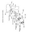
- a keyhole drill guide 400 C(also sometimes referred to as a “keystone guide”) may be used ( FIGS. 39 and 40 ).
- Keyhole drill guide 400 Cis generally similar to the keyhole drill guide 400 disclosed above, except that keyhole drill guide 400 C has, in addition to its two guide holes 425 C, 435 C, a shear rib guidehole 440 C for forming shear rib keyhole 897 C.
- Implant 800 C(and drill guide 400 C) may be used in an open wedge, high tibial osteotomy in a manner which is generally similar to that previously described with respect to implant 800 (and drill guide 400 ), except that the bridged graft containment unit, i.e., posterior graft containment arm (GCA) 805 C, bridge 892 C and anterior graft containment arm (GCA) 815 C, is installed as a single construction. Furthermore, when drill guide 400 C is used to form keyholes 85 C and 90 C, it is also used to form shear rib keyhole 897 C.
- the bridged graft containment uniti.e., posterior graft containment arm (GCA) 805 C
- GCAposterior graft containment arm
- GCAanterior graft containment arm
- implant 800 Cwith two graft containment arms, e.g., posterior graft containment arm (GCA) 805 C and anterior graft containment arm (GCA) 815 C, is frequently preferred. However, in some circumstances, it may be desirable to omit one or both of posterior graft containment arm (GCA) 805 C and anterior graft containment arm (GCA) 815 C. Thus, in one preferred form of the invention, implant 800 C comprises only base 810 C and omits both posterior graft containment arm (GCA) 805 C and anterior graft containment arm (GCA) 815 C.
- GCAposterior graft containment arm
- GCAanterior graft containment arm
- Providing implant 800 C with a pair of keys 820 C, 825 Cis generally preferred. However, in some circumstances, it may be desirable to omit one or the other, or both, of keys 820 C, 825 C. Furthermore, in other circumstances, it may be desirable to provide more than two keys, e.g., to provide three keys.
- each of the keys 820 C, 825 Cmay include more than one bore 833 C, 834 C.
- a keymay include two bores, one angled leftwardly so as to direct a fixation screw leftwardly into the tibia to the left of the key, and/or one angled rightwardly so as to direct a fixation screw rightwardly into the tibia to the right of the key.
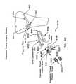
- shear rib keyhole 897 Ccan be formed using a conventional drill. More preferably, however, and looking now at FIGS. 40 and 41 , shear rib keyhole 897 C is formed using a shear rib end mill 445 C.
- Shear rib end mill 445 Cgenerally comprises a shaft 450 C having cutting edges 455 C, a corner radius 460 C and flutes 465 C.
- a relief area 470 Cis formed just proximal to corner radius 460 C.
- An end stop 475 Climits, through engagement with drill guide 400 C, the depth of shear rib keyhole 897 C.
- Implant 800 Dis generally similar to the implant 800 C disclosed above, except that implant 800 D is intended to be used with expansion thread fixation screws that terminate within the keys.
- implant 800 Dcomprises a posterior graft containment arm (GCA) 805 D, a base 810 D and an anterior graft containment arm (GCA) 815 D.
- a bridge 892 Dconnects the distal end of posterior graft containment arm (GCA) 805 D with the distal end of anterior graft containment arm (GCA) 815 D.
- bridge 892 Dmay be provided with a distal tab 898 D to be received in oversized hole 95 D.
- Distal tab 898 Dserves to improve the alignment and stability of implant 800 D when seated in wedge-like opening 25 D.
- a shear rib 890 Dis formed in base 810 D, laterally displaced from the two keys 820 D, 825 D (which are themselves arranged in an “over-under” configuration).
- Posterior graft containment arm (GCA) 805 Dincludes a recess 893 D
- base 810 Dincludes a shoulder 894 D
- posterior graft containment arm (GCA) 805 Dcan mate with base 810 D.
- Anterior graft containment arm (GCA) 815 Dincludes a recess 895 D
- implant base 810 Dincludes a shoulder 896 D, whereby anterior graft containment arm (GCA) 815 D can mate with base 810 D.
- Posterior graft containment arm (GCA) 805 D, and/or anterior graft containment arm (GCA) 815 D,may include raised points or dimples 831 D (not shown).
- Keys 820 D, 825 Deach include a bore 833 D, 834 D, respectively. Bores 833 D, 834 D receive expansion thread fixation screws 865 D for fixing implant 800 D to the tibia. Expansion thread fixation screws 865 D are configured so as to intentionally terminate within bores 833 D, 834 D. This is in contrast to implant 800 C which allows expansion thread fixation screws 865 to extend out of the distal ends of bores 833 C, 834 C and then into the adjacent bone.
- the bores 833 D, 834 Dmay be axially aligned with the longitudinal axes of keys 820 D, 825 D, respectively. Keys 820 D, 825 D may also include external ribs 836 D (not shown).
- External ribs 836 Dmay extend longitudinally or circumferentially.
- Keys 820 D, 825 Dmay also be slotted (i.e., in a manner analogous to the slots provided in keys 820 , 825 of implant 800 ), whereby to permit keys 820 D, 825 D to expand when expansion thread fixation screws 865 D are received in bores 833 D, 834 D.
- the external thread on the expansion thread fixation screws 865 Dmay be tapered so as to expand the bore into the cancellous bone of the tibia when the expansion thread fixation screws are received within bores 833 D, 834 D.
- the internal thread on bores 833 D, 834 Dmay be tapered so as to expand the bore into the cancellous bone of the tibia when the expansion thread fixation screws 865 D are received within bores 833 D, 834 D.
- Shear rib 890 Dis laterally offset from keys 820 D, 825 D, which are arranged in an “over-under” configuration. Shear rib 890 D projects above and below the top and bottom surfaces of base 810 D. Among other things, it has been found that the provision of shear rib 890 D provides, at the base of the implant, excellent load-bearing characteristics and substantial resistance to rotational and shear forces.
- a keyhole drill guideis used as disclosed above.
- Implant 800 D(and an associated drill guide) may be used in an open wedge, high tibial osteotomy in a manner which is generally similar to that previously described with respect to implant 800 C (and drill guide 400 C), except that expansion thread fixation screws 865 D terminate within bores 833 D, 834 D.
- implant 800 Dwith two graft containment arms, e.g., posterior graft containment arm (GCA) 805 D and anterior graft containment arm (GCA) 815 D, is frequently preferred. However, in some circumstances, it may be desirable to omit one or both of posterior graft containment arm (GCA) 805 D and anterior graft containment arm (GCA) 815 D. Thus, in one preferred form of the invention, implant 800 D comprises only base 810 D and omits both posterior graft containment arm (GCA) 805 D and anterior graft containment arm (GCA) 815 D.
- GCAposterior graft containment arm
- GCAanterior graft containment arm
- Providing implant 800 D with a pair of keys 820 D, 825 Dis generally preferred. However, in some circumstances, it may be desirable to omit one or the other, or both, of keys 820 D, 825 D. Furthermore, in other circumstances, it may be desirable to provide more than two keys, e.g., to provide three keys.
- each of the keys 820 D, 825 Dmay include more than one bore 833 D, 834 D.
- one keymay be expanded by multiple expansion thread fixation screws 865 D.
- implant 800 Dis highly similar to the construction of implant 800 C, the construction of implant 800 D provides expansion thread fixation screws 865 D that intentionally terminate within bores 833 D, 834 D, and hence within the body of the key, i.e., they do not penetrate into the adjacent bone.
- Implant 800 Ealso formed in accordance with the present invention.
- Implant 800 Eis generally similar to the implant 800 C disclosed above, except that implant 800 E provides counterbores 833 EE, 834 EE, respectively, for receiving draw nuts 867 E, 868 E, which in turn include bores 833 EEE, 834 EEE, respectively.
- implant 800 Ecomprises a posterior graft containment arm (GCA) 805 E, a base 810 E and an anterior graft containment arm (GCA) 815 E.
- a bridge 892 Econnects the distal end of posterior graft containment arm (GCA) 805 E with the distal end of anterior graft containment arm (GCA) 815 E.
- bridge 892 Emay be provided with a distal tab 898 E to be received in oversized hole 95 E.
- Distal tab 898 Eserves to improve the alignment and stability of implant 800 E when seated in wedge-like opening 25 E.
- a shear rib 890 Eis formed in base 810 E, laterally displaced from the two keys 820 E, 825 E (which are themselves arranged in an “over-under” configuration).
- Posterior graft containment arm (GCA) 805 Eincludes a recess 893 E, and base 810 E includes a shoulder 894 E, whereby posterior graft containment arm (GCA) 805 E can mate with base 810 E.
- Anterior graft containment arm (GCA) 815 Eincludes a recess 895 E, and implant base 810 E includes a shoulder 896 E, whereby anterior graft containment arm (GCA) 815 E can mate with base 810 E.
- Posterior graft containment arm (GCA) 805 E, and/or anterior graft containment arm (GCA) 815 E,may include raised points or dimples 831 E (not shown).
- Keys 820 E, 825 Eeach include a bore 833 E, 834 E, respectively, and a counterbore 833 EE, 834 EE, respectively.
- Draw nuts 867 E, 868 Eare positioned at the distal ends of bores 833 E, 834 E, in counterbores 833 EE, 834 EE, respectively.
- Draw nuts 867 E, 868 Eeach include a bore 833 EEE, 834 EEE, respectively, such that when expansion thread fixation screws 865 E are received in bores 833 E, 834 E and bores 833 EEE, 834 EEE of draw nuts 867 E, 868 E, the draw nuts will be drawn into counterbores 833 EE, 834 EE, thereby enhancing the expansion of keys 820 E, 825 E, whereby to securely fix implant 800 E to the tibia.
- the bores 833 E, 834 Emay be axially aligned with the longitudinal axes of keys 820 E, 825 E, respectively.
- Keys 820 E, 825 Emay also include external ribs 836 E (not shown). External ribs 836 E may extend longitudinally or circumferentially.
- Keys 820 E, 825 Emay also be slotted (i.e., in a manner analogous to the slots provided in keys 820 , 825 of implant 800 ), whereby to permit keys 820 E, 825 E to expand when expansion thread fixation screws 865 E are received in bores 833 E, 834 E and in bores 833 EEE, 834 EEE of draw nuts 867 E, 868 E.
- Shear rib 890 Eis laterally offset from keys 820 E, 825 E, which are arranged in an “over-under” configuration. Shear rib 890 E projects above and below the top and bottom surfaces of base 810 E. Among other things, it has been found that the provision of shear rib 890 E provides, at the base of the implant, excellent load-bearing characteristics and substantial resistance to rotational and shear forces.
- a keyhole drill guideis used as disclosed above.
- Implant 800 E(and an associated drill guide) may be used in an open wedge, high tibial osteotomy in a manner which is generally similar to that previously described with respect to implant 800 C (and drill guide 400 C).
- Providing implant 800 E with two graft containment arms, e.g., posterior graft containment arm (GCA) 805 E and anterior graft containment arm (GCA) 815 Eis frequently preferred. However, in some circumstances, it may be desirable to omit one or both of posterior graft containment arm (GCA) 805 E and anterior graft containment arm (GCA) 815 E.
- implant 800 Ecomprises only base 810 E and omits both posterior graft containment arm (GCA) 805 E and anterior graft containment arm (GCA) 815 E.
- Providing implant 800 E with a pair of keys 820 E, 825 Eis generally preferred. However, in some circumstances, it may be desirable to omit one or the other, or both, of keys 820 E, 825 E. Furthermore, in other circumstances, it may be desirable to provide more than two keys, e.g., to provide three keys.
- each of the keys 820 E, 825 Emay include more than one bore 833 E, 834 E and counterbore 833 EE, 834 EE and more than one draw nut 867 E, 868 E.
- one keymay be expanded by multiple expansion thread fixation screws 865 E.
- implant 800 Eis highly similar to the construction of implant 800 C, the construction of implant 800 E provides draw nuts 867 E, 868 E positioned at the distal ends of bores 833 E, 834 E, received within counterbores 833 EE, 834 EE, respectively.
- Implant 800 Falso formed in accordance with the present invention.
- Implant 800 Fis generally similar to the implant 800 C disclosed above, except that implant 800 F provides open keys having opposed longitudinal edges. Furthermore, the open keys include threaded recesses.
- implant 800 Fcomprises a posterior graft containment arm (GCA) 805 F, a base 810 F and an anterior graft containment arm (GCA) 815 F.
- a bridge 892 Fconnects the distal end of posterior graft containment arm (GCA) 805 F with the distal end of anterior graft containment arm (GCA) 815 F.
- bridge 892 Fmay be provided with a distal tab 898 F to be received in oversized hole 95 F.
- Distal tab 898 Fserves to improve the alignment and stability of implant 800 F when seated in wedge-like opening 25 F.
- a shear rib 890 Fis formed in base 810 F, laterally displaced from two open keys 820 F, 825 F (which are themselves arranged in an “over-under” configuration).
- Posterior graft containment arm (GCA) 805 Fincludes a recess 893 F
- base 810 Fincludes a shoulder 894 F
- posterior graft containment arm (GCA) 805 Fcan mate with base 810 F.
- Anterior graft containment arm (GCA) 815 Fincludes a recess 895 F
- implant base 810 Fincludes a shoulder 896 F, whereby anterior graft containment arm (GCA) 815 F can mate with base 810 F.
- Posterior graft containment arm (GCA) 805 F, and/or anterior graft containment arm (GCA) 815 F,may include raised points or dimples 831 F (not shown).
- Open keys 820 F, 825 Feach include a threaded recess 833 F, 834 F, respectively. It should be appreciated that due to the geometry of the open keys 820 F, 825 F when expansion thread fixation screws 865 F are received in the threaded recesses 833 F, 834 F, a portion of the threaded surface of expansion thread fixation screws 865 F are exposed to, and hence directly engage, the adjacent bone. This is in contrast with implant 800 C, wherein the fixation screws 865 C are received within closed keys 820 C, 825 C.
- the keyholes 85 F, 90 Fmay be further prepared by tapping with a tap 899 F (not shown) with a corresponding thread pitch to that of expansion thread fixation screws 865 F.
- Threaded recesses 833 F, 834 Fmay be axially aligned with the longitudinal axes of open keys 820 F, 825 F, respectively.
- Open keys 820 F, 825 Fmay also include external ribs 836 F. External ribs 836 F may extend longitudinally or circumferentially.
- Open keys 820 F, 825 Fmay also be only partially opened, i.e., along only a portion of the length of the keys (i.e., in a manner analogous to the slots provided in keys 820 , 825 of implant 800 ), whereby to provide open keys 820 F, 825 F with greater structural integrity.
- Shear rib 890 Fis laterally offset from open keys 820 F, 825 F, which are arranged in an “over-under” configuration. Shear rib 890 F projects above and below the top and bottom surfaces of base 810 F. Among other things, it has been found that the provision of shear rib 890 F provides, at the base of the implant, excellent load-bearing characteristics and substantial resistance to rotational and shear forces.
- a keyhole drill guideis used as disclosed above.
- Implant 800 F(and the associated drill guide) may be used in an open wedge, high tibial osteotomy in a manner which is generally similar to that previously described with respect to implant 800 C (and drill guide 400 C), except that the bridged graft containment unit, i.e., posterior graft containment arm (GCA) 805 F, bridge 892 F and anterior graft containment arm (GCA) 815 F, is installed as a single construction. Furthermore, when drill guide 400 F is used to form keyholes 85 F and 90 F, it is also used to form shear rib keyhole 897 F.
- GCAposterior graft containment arm
- GCAanterior graft containment arm
- implant 800 Fwith two graft containment arms, e.g., posterior graft containment arm (GCA) 805 F and anterior graft containment arm (GCA) 815 F, is frequently preferred. However, in some circumstances, it may be desirable to omit one or both of posterior graft containment arm (GCA) 805 F and anterior graft containment arm (GCA) 815 F. Thus, in one preferred form of the invention, implant 800 F comprises only base 810 F and omits both posterior graft containment arm (GCA) 805 F and anterior graft containment arm (GCA) 815 F.
- GCAposterior graft containment arm
- GCAanterior graft containment arm
- Implant 800 F with a pair of open keys 820 F, 825 Fis generally preferred. However, in some circumstances, it may be desirable to omit one or the other, or both, of open keys 820 F, 825 F. Furthermore, in other circumstances, it may be desirable to provide more than two open keys, e.g., to provide three open keys.
- each of the open keys 820 F, 825 Fmay include more than one threaded recess 833 F, 834 F.
- open keysmay contain multiple, but not overlapping, recesses to receive multiple expansion thread fixation screws 865 F.
- an open keymay include two recesses, one angled leftwardly so as to direct a fixation screw leftwardly into the tibia to the left of the open key, and/or one angled rightwardly so as to direct a fixation screw rightwardly into the tibia to the right of the open key.
- implant 800 Fis highly similar to the construction of implant 800 C, the construction of implant 800 F provides keys which allow a portion of the threaded surface of expansion thread fixation screws 865 F to directly engage the adjacent bone.
- a high tibial, dome osteotomymay be performed on the knee.
- the present inventionprovides a method and apparatus for performing a high tibial, dome osteotomy.
- the present inventionprovides increased precision and reduced trauma when adjusting the lateral and/or angular disposition of the tibial plateau relative to the lower portion of the tibia, and provides increased stability to the upper and lower portions of the tibia while healing occurs.
- FIGS. 51-66there is shown a novel method and apparatus for performing a high tibial, dome osteotomy.
- FIG. 51shows tibia 10 in its native condition, with a tibial plateau 30 which requires adjustment in lateral and/or angular disposition.
- an arcuate osteotomy cut 20is formed in tibia 10 so as to subdivide the tibia into an upper portion 10 A and a lower portion 10 B.
- the arcuate osteotomy cut 20may be formed so that upper portion 10 A has a convex surface 20 A and lower portion 10 B has a concave surface 20 B.
- upper portion 10 A and lower portion 10 Bare manipulated ( FIGS. 53 and 54 ) so as to adjust the lateral and/or angular dispositions of the two portions relative to one another, whereby to adjust the disposition of tibial plateau 30 in the desired manner.
- fixation holes 92 , 93extend into different tibial portions 10 A, 10 B, e.g., fixation hole 92 extends into upper portion 10 A and fixation hole 93 extends into lower portion 10 B. If desired, fixation holes 92 , 93 may also deviate from one another in a lateral sense, or they may converge toward one another in a lateral sense.
- implant 800 Gis deployed in the tibia ( FIG. 58 ). More particularly, implant 800 G comprises a pair of keys 820 G, 825 G connected by a bridge 826 G. Keys 820 G, 825 G include bores 833 G, 834 G, respectively, for receiving fixation screws. Bores 833 G, 834 G are aligned with fixation holes 92 , 93 , respectively. Fixation screws 865 G are then inserted through bores 833 G, 834 G and into fixation holes 92 , 93 ( FIG. 59 ). As noted above, and as can be seen in FIGS. 60-62 , one fixation screw 865 G preferably extends into upper portion 10 A of the tibia, and the other fixation screw 865 G preferably extends into lower portion 10 B of the tibia.
- implant 800 Gstabilizes upper portion 10 A and lower portion 10 B relative to one another while healing occurs.
- the “side-by-side” key configurationprovides, at the base of the implant, excellent load-bearing characteristics and substantial resistance to rotational and shear forces.
- the arcuate osteotomy cut 20is shown formed so that upper portion 10 A has a convex surface 20 A and lower portion 10 B has a concave surface 20 B.
- arcuate osteotomy cut 20it is also possible to form arcuate osteotomy cut 20 so that upper portion 10 A has a concave surface 20 C and lower portion 10 B has a convex surface 20 D.
- FIGS. 63-66show an approach for performing a high tibial, dome osteotomy where arcuate osteotomy cut 20 is formed so that upper portion 10 A has a concave surface 20 C and lower portion 10 B has a convex surface 20 D.
- implant 800 Gis shown formed so that its keys 820 G, 825 G are disposed in a “side-by-side” configuration. However, it is also possible to form implant 800 G so that its keys 820 G, 825 G are disposed in an “over-under” configuration.
- FIGS. 67-78show a method and apparatus for performing a high tibial, dome osteotomy where (i) the arcuate osteotomy cut 20 is shown formed so that upper portion 10 A has a convex surface 20 A and lower portion 10 B has a concave surface 20 B, and (ii) implant 800 H is formed so that its keys 820 H, 825 H are disposed in an “over-under” configuration.
- FIGS. 79-82show a method and apparatus for performing a high tibial, dome osteotomy where (i) arcuate osteotomy cut 20 is formed so that upper portion 10 A has a concave surface 20 C and lower portion 10 B has a convex surface 20 D, and (ii) implant 800 H is formed so that its keys 820 H, 825 H are disposed in an “over-under” configuration.
- implants 800 G, 800 Hare shown with a construction comprising a pair of keys connected by a bridge.
- FIGS. 83-94show an implant 800 I having a single key configuration. More particularly, implant 800 I comprises a single key 822 I for disposition in a single keyhole 87 . Implant 822 I comprises two bores 833 I, 834 I for receiving fixation screws 865 I therein. Key 822 I may have a variety of different cross-sectional shapes, e.g., circular, ovoid, polygonal (e.g., triangular, rectangular, hexagonal, etc.), etc.
- the present inventionis discussed in the context of performing an osteotomy using an antero-medial approach so as to effect a medial osteotomy.
- the present inventionmay also be used in antero-lateral approaches so as to effect a lateral opening wedge osteotomy, or in other approaches which will be well known to those skilled in the art.
Landscapes
- Health & Medical Sciences (AREA)
- Surgery (AREA)
- Life Sciences & Earth Sciences (AREA)
- Orthopedic Medicine & Surgery (AREA)
- Biomedical Technology (AREA)
- Public Health (AREA)
- Veterinary Medicine (AREA)
- Engineering & Computer Science (AREA)
- Nuclear Medicine, Radiotherapy & Molecular Imaging (AREA)
- Heart & Thoracic Surgery (AREA)
- Medical Informatics (AREA)
- Molecular Biology (AREA)
- Animal Behavior & Ethology (AREA)
- General Health & Medical Sciences (AREA)
- Dentistry (AREA)
- Oral & Maxillofacial Surgery (AREA)
- Neurology (AREA)
- Surgical Instruments (AREA)
- Prostheses (AREA)
Abstract
Description
Claims (31)
Priority Applications (1)
| Application Number | Priority Date | Filing Date | Title |
|---|---|---|---|
| US11/888,802US8062301B2 (en) | 2005-01-31 | 2007-08-02 | Method and apparatus for performing a high tibial, dome osteotomy |
Applications Claiming Priority (15)
| Application Number | Priority Date | Filing Date | Title |
|---|---|---|---|
| US11/047,551US8083746B2 (en) | 2004-05-07 | 2005-01-31 | Open wedge osteotomy system and surgical method |
| US11/047,159US20050251147A1 (en) | 2004-05-07 | 2005-01-31 | Open wedge osteotomy system and surgical method |
| US11/350,333US8496662B2 (en) | 2005-01-31 | 2006-02-08 | Method and apparatus for forming a wedge-like opening in a bone for an open wedge osteotomy |
| US11/352,103US8211112B2 (en) | 2005-01-31 | 2006-02-09 | Multi-part implant for open wedge knee osteotomies |
| US11/396,490US8888785B2 (en) | 2005-01-31 | 2006-04-03 | Method and apparatus for performing an open wedge, high tibial osteotomy |
| US83517206P | 2006-08-02 | 2006-08-02 | |
| US83529206P | 2006-08-03 | 2006-08-03 | |
| US83526906P | 2006-08-03 | 2006-08-03 | |
| US83526806P | 2006-08-03 | 2006-08-03 | |
| US84752706P | 2006-09-27 | 2006-09-27 | |
| US86059506P | 2006-11-22 | 2006-11-22 | |
| US11/607,321US7967823B2 (en) | 2005-01-31 | 2006-12-01 | Method and apparatus for performing an open wedge, high tibial osteotomy |
| US11/644,218US7935119B2 (en) | 2005-01-31 | 2006-12-22 | Method for performing an open wedge, high tibial osteotomy |
| PCT/US2007/017273WO2008016687A2 (en) | 2006-08-02 | 2007-08-02 | Method and apparatus for performing a high tibial, dome osteotomy |
| US11/888,802US8062301B2 (en) | 2005-01-31 | 2007-08-02 | Method and apparatus for performing a high tibial, dome osteotomy |
Related Parent Applications (1)
| Application Number | Title | Priority Date | Filing Date |
|---|---|---|---|
| US11/047,159Continuation-In-PartUS20050251147A1 (en) | 2004-05-07 | 2005-01-31 | Open wedge osteotomy system and surgical method |
Publications (2)
| Publication Number | Publication Date |
|---|---|
| US20080147074A1 US20080147074A1 (en) | 2008-06-19 |
| US8062301B2true US8062301B2 (en) | 2011-11-22 |
Family
ID=38997687
Family Applications (1)
| Application Number | Title | Priority Date | Filing Date |
|---|---|---|---|
| US11/888,802Active2027-12-18US8062301B2 (en) | 2005-01-31 | 2007-08-02 | Method and apparatus for performing a high tibial, dome osteotomy |
Country Status (2)
| Country | Link |
|---|---|
| US (1) | US8062301B2 (en) |
| WO (1) | WO2008016687A2 (en) |
Cited By (135)
| Publication number | Priority date | Publication date | Assignee | Title |
|---|---|---|---|---|
| US20060020343A1 (en)* | 2002-12-03 | 2006-01-26 | Ek Steven W | System for articular surface replacement |
| US20100152782A1 (en)* | 2006-02-27 | 2010-06-17 | Biomet Manufactring Corp. | Patient Specific High Tibia Osteotomy |
| US20100268238A1 (en)* | 2009-04-17 | 2010-10-21 | Arthrosurface Incorporated | Glenoid Resurfacing System and Method |
| US20110213376A1 (en)* | 2010-02-26 | 2011-09-01 | Biomet Sports Medicine, Llc | Patient-Specific Osteotomy Devices and Methods |
| US20110218540A1 (en)* | 2005-01-31 | 2011-09-08 | Ammann Kelly G | Method and Apparatus for Performing An Open Wedge Osteotomy |
| US8147559B2 (en) | 2000-05-01 | 2012-04-03 | Arthrosurface Incorporated | System and method for joint resurface repair |
| US8177841B2 (en) | 2000-05-01 | 2012-05-15 | Arthrosurface Inc. | System and method for joint resurface repair |
| US8282646B2 (en) | 2006-02-27 | 2012-10-09 | Biomet Manufacturing Corp. | Patient specific knee alignment guide and associated method |
| US8298237B2 (en) | 2006-06-09 | 2012-10-30 | Biomet Manufacturing Corp. | Patient-specific alignment guide for multiple incisions |
| US8377066B2 (en) | 2006-02-27 | 2013-02-19 | Biomet Manufacturing Corp. | Patient-specific elbow guides and associated methods |
| US8388624B2 (en) | 2003-02-24 | 2013-03-05 | Arthrosurface Incorporated | Trochlear resurfacing system and method |
| US8398646B2 (en) | 2006-06-09 | 2013-03-19 | Biomet Manufacturing Corp. | Patient-specific knee alignment guide and associated method |
| US8407067B2 (en) | 2007-04-17 | 2013-03-26 | Biomet Manufacturing Corp. | Method and apparatus for manufacturing an implant |
| US8473305B2 (en) | 2007-04-17 | 2013-06-25 | Biomet Manufacturing Corp. | Method and apparatus for manufacturing an implant |
| US8486150B2 (en) | 2007-04-17 | 2013-07-16 | Biomet Manufacturing Corp. | Patient-modified implant |
| US8523872B2 (en) | 2002-12-03 | 2013-09-03 | Arthrosurface Incorporated | Tibial resurfacing system |
| US8532807B2 (en) | 2011-06-06 | 2013-09-10 | Biomet Manufacturing, Llc | Pre-operative planning and manufacturing method for orthopedic procedure |
| US8535387B2 (en) | 2006-02-27 | 2013-09-17 | Biomet Manufacturing, Llc | Patient-specific tools and implants |
| US8540717B2 (en) | 2000-05-01 | 2013-09-24 | Arthrosurface Incorporated | System and method for joint resurface repair |
| US8556902B2 (en) | 2002-12-03 | 2013-10-15 | Arthrosurface Incorporated | System and method for retrograde procedure |
| US8568487B2 (en) | 2006-02-27 | 2013-10-29 | Biomet Manufacturing, Llc | Patient-specific hip joint devices |
| US8591516B2 (en) | 2006-02-27 | 2013-11-26 | Biomet Manufacturing, Llc | Patient-specific orthopedic instruments |
| US8597365B2 (en) | 2011-08-04 | 2013-12-03 | Biomet Manufacturing, Llc | Patient-specific pelvic implants for acetabular reconstruction |
| US8603180B2 (en) | 2006-02-27 | 2013-12-10 | Biomet Manufacturing, Llc | Patient-specific acetabular alignment guides |
| US8608748B2 (en) | 2006-02-27 | 2013-12-17 | Biomet Manufacturing, Llc | Patient specific guides |
| US8608749B2 (en) | 2006-02-27 | 2013-12-17 | Biomet Manufacturing, Llc | Patient-specific acetabular guides and associated instruments |
| US8663230B2 (en) | 2002-12-03 | 2014-03-04 | Arthrosurface Incorporated | Retrograde delivery of resurfacing devices |
| US8668700B2 (en) | 2011-04-29 | 2014-03-11 | Biomet Manufacturing, Llc | Patient-specific convertible guides |
| US8715289B2 (en) | 2011-04-15 | 2014-05-06 | Biomet Manufacturing, Llc | Patient-specific numerically controlled instrument |
| US8764760B2 (en) | 2011-07-01 | 2014-07-01 | Biomet Manufacturing, Llc | Patient-specific bone-cutting guidance instruments and methods |
| US8858561B2 (en) | 2006-06-09 | 2014-10-14 | Blomet Manufacturing, LLC | Patient-specific alignment guide |
| US8864769B2 (en) | 2006-02-27 | 2014-10-21 | Biomet Manufacturing, Llc | Alignment guides with patient-specific anchoring elements |
| US8900244B2 (en) | 2006-02-27 | 2014-12-02 | Biomet Manufacturing, Llc | Patient-specific acetabular guide and method |
| US8920512B2 (en) | 2012-12-19 | 2014-12-30 | Biomet Sports Medicine, Llc | Method and apparatus for pre-forming a high tibial osteotomy |
| US8926615B2 (en) | 2002-12-03 | 2015-01-06 | Arthrosurface, Inc. | System and method for retrograde procedure |
| US8956364B2 (en) | 2011-04-29 | 2015-02-17 | Biomet Manufacturing, Llc | Patient-specific partial knee guides and other instruments |
| US8961614B2 (en) | 2004-11-22 | 2015-02-24 | Arthrosurface, Inc. | Articular surface implant and delivery system |
| US9055955B2 (en) | 2000-05-01 | 2015-06-16 | Arthrosurface Inc. | Bone resurfacing system and method |
| US9060788B2 (en) | 2012-12-11 | 2015-06-23 | Biomet Manufacturing, Llc | Patient-specific acetabular guide for anterior approach |
| US9066716B2 (en) | 2011-03-30 | 2015-06-30 | Arthrosurface Incorporated | Suture coil and suture sheath for tissue repair |
| US9066734B2 (en) | 2011-08-31 | 2015-06-30 | Biomet Manufacturing, Llc | Patient-specific sacroiliac guides and associated methods |
| US9084618B2 (en) | 2011-06-13 | 2015-07-21 | Biomet Manufacturing, Llc | Drill guides for confirming alignment of patient-specific alignment guides |
| US9113971B2 (en) | 2006-02-27 | 2015-08-25 | Biomet Manufacturing, Llc | Femoral acetabular impingement guide |
| US9173661B2 (en) | 2006-02-27 | 2015-11-03 | Biomet Manufacturing, Llc | Patient specific alignment guide with cutting surface and laser indicator |
| US9204977B2 (en) | 2012-12-11 | 2015-12-08 | Biomet Manufacturing, Llc | Patient-specific acetabular guide for anterior approach |
| US9237950B2 (en) | 2012-02-02 | 2016-01-19 | Biomet Manufacturing, Llc | Implant with patient-specific porous structure |
| US9241745B2 (en) | 2011-03-07 | 2016-01-26 | Biomet Manufacturing, Llc | Patient-specific femoral version guide |
| US9271744B2 (en) | 2010-09-29 | 2016-03-01 | Biomet Manufacturing, Llc | Patient-specific guide for partial acetabular socket replacement |
| US9289253B2 (en) | 2006-02-27 | 2016-03-22 | Biomet Manufacturing, Llc | Patient-specific shoulder guide |
| US9295497B2 (en) | 2011-08-31 | 2016-03-29 | Biomet Manufacturing, Llc | Patient-specific sacroiliac and pedicle guides |
| US9301812B2 (en) | 2011-10-27 | 2016-04-05 | Biomet Manufacturing, Llc | Methods for patient-specific shoulder arthroplasty |
| US9339278B2 (en) | 2006-02-27 | 2016-05-17 | Biomet Manufacturing, Llc | Patient-specific acetabular guides and associated instruments |
| US9345548B2 (en) | 2006-02-27 | 2016-05-24 | Biomet Manufacturing, Llc | Patient-specific pre-operative planning |
| US9351743B2 (en) | 2011-10-27 | 2016-05-31 | Biomet Manufacturing, Llc | Patient-specific glenoid guides |
| US9358029B2 (en) | 2006-12-11 | 2016-06-07 | Arthrosurface Incorporated | Retrograde resection apparatus and method |
| US9357989B2 (en) | 2000-05-01 | 2016-06-07 | Arthrosurface Incorporated | System and method for joint resurface repair |
| US9386993B2 (en) | 2011-09-29 | 2016-07-12 | Biomet Manufacturing, Llc | Patient-specific femoroacetabular impingement instruments and methods |
| US9393028B2 (en) | 2009-08-13 | 2016-07-19 | Biomet Manufacturing, Llc | Device for the resection of bones, method for producing such a device, endoprosthesis suited for this purpose and method for producing such an endoprosthesis |
| US9408616B2 (en) | 2014-05-12 | 2016-08-09 | Biomet Manufacturing, Llc | Humeral cut guide |
| US9451973B2 (en) | 2011-10-27 | 2016-09-27 | Biomet Manufacturing, Llc | Patient specific glenoid guide |
| US9468448B2 (en) | 2012-07-03 | 2016-10-18 | Arthrosurface Incorporated | System and method for joint resurfacing and repair |
| US9492200B2 (en) | 2013-04-16 | 2016-11-15 | Arthrosurface Incorporated | Suture system and method |
| US9498233B2 (en) | 2013-03-13 | 2016-11-22 | Biomet Manufacturing, Llc. | Universal acetabular guide and associated hardware |
| US9517145B2 (en) | 2013-03-15 | 2016-12-13 | Biomet Manufacturing, Llc | Guide alignment system and method |
| US9554910B2 (en) | 2011-10-27 | 2017-01-31 | Biomet Manufacturing, Llc | Patient-specific glenoid guide and implants |
| US9561040B2 (en) | 2014-06-03 | 2017-02-07 | Biomet Manufacturing, Llc | Patient-specific glenoid depth control |
| US9579107B2 (en) | 2013-03-12 | 2017-02-28 | Biomet Manufacturing, Llc | Multi-point fit for patient specific guide |
| US9662126B2 (en) | 2009-04-17 | 2017-05-30 | Arthrosurface Incorporated | Glenoid resurfacing system and method |
| US9675400B2 (en) | 2011-04-19 | 2017-06-13 | Biomet Manufacturing, Llc | Patient-specific fracture fixation instrumentation and method |
| US9795399B2 (en) | 2006-06-09 | 2017-10-24 | Biomet Manufacturing, Llc | Patient-specific knee alignment guide and associated method |
| US9820868B2 (en) | 2015-03-30 | 2017-11-21 | Biomet Manufacturing, Llc | Method and apparatus for a pin apparatus |
| US9826981B2 (en) | 2013-03-13 | 2017-11-28 | Biomet Manufacturing, Llc | Tangential fit of patient-specific guides |
| US9826994B2 (en) | 2014-09-29 | 2017-11-28 | Biomet Manufacturing, Llc | Adjustable glenoid pin insertion guide |
| US9833245B2 (en) | 2014-09-29 | 2017-12-05 | Biomet Sports Medicine, Llc | Tibial tubercule osteotomy |
| US9839436B2 (en) | 2014-06-03 | 2017-12-12 | Biomet Manufacturing, Llc | Patient-specific glenoid depth control |
| US9839438B2 (en) | 2013-03-11 | 2017-12-12 | Biomet Manufacturing, Llc | Patient-specific glenoid guide with a reusable guide holder |
| US9861492B2 (en) | 2014-03-07 | 2018-01-09 | Arthrosurface Incorporated | Anchor for an implant assembly |
| US9907659B2 (en) | 2007-04-17 | 2018-03-06 | Biomet Manufacturing, Llc | Method and apparatus for manufacturing an implant |
| US9918740B2 (en) | 2006-02-27 | 2018-03-20 | Biomet Manufacturing, Llc | Backup surgical instrument system and method |
| US9968376B2 (en) | 2010-11-29 | 2018-05-15 | Biomet Manufacturing, Llc | Patient-specific orthopedic instruments |
| US10226262B2 (en) | 2015-06-25 | 2019-03-12 | Biomet Manufacturing, Llc | Patient-specific humeral guide designs |
| US10278711B2 (en) | 2006-02-27 | 2019-05-07 | Biomet Manufacturing, Llc | Patient-specific femoral guide |
| US10282488B2 (en) | 2014-04-25 | 2019-05-07 | Biomet Manufacturing, Llc | HTO guide with optional guided ACL/PCL tunnels |
| US10292713B2 (en) | 2015-01-28 | 2019-05-21 | First Ray, LLC | Freeform tri-planar osteotomy guide and method |
| US10357260B2 (en) | 2015-11-02 | 2019-07-23 | First Ray, LLC | Orthopedic fastener, retainer, and guide methods |
| US10376367B2 (en) | 2015-07-02 | 2019-08-13 | First Ray, LLC | Orthopedic fasteners, instruments and methods |
| US10376268B2 (en) | 2015-02-19 | 2019-08-13 | First Ray, LLC | Indexed tri-planar osteotomy guide and method |
| US10492798B2 (en) | 2011-07-01 | 2019-12-03 | Biomet Manufacturing, Llc | Backup kit for a patient-specific arthroplasty kit assembly |
| US10512470B1 (en) | 2016-08-26 | 2019-12-24 | Treace Medical Concepts, Inc. | Osteotomy procedure for correcting bone misalignment |
| US10524808B1 (en) | 2016-11-11 | 2020-01-07 | Treace Medical Concepts, Inc. | Devices and techniques for performing an osteotomy procedure on a first metatarsal to correct a bone misalignment |
| US10555757B2 (en) | 2014-07-15 | 2020-02-11 | Treace Medical Concepts, Inc. | Bone positioning and cutting system and method |
| US10561426B1 (en) | 2015-01-07 | 2020-02-18 | Treace Medical Concepts, Inc. | Bone cutting guide systems and methods |
| US10568647B2 (en) | 2015-06-25 | 2020-02-25 | Biomet Manufacturing, Llc | Patient-specific humeral guide designs |
| US10575862B2 (en) | 2015-09-18 | 2020-03-03 | Treace Medical Concepts, Inc. | Joint spacer systems and methods |
| US10603179B2 (en) | 2006-02-27 | 2020-03-31 | Biomet Manufacturing, Llc | Patient-specific augments |
| US10624748B2 (en) | 2014-03-07 | 2020-04-21 | Arthrosurface Incorporated | System and method for repairing articular surfaces |
| US10624752B2 (en) | 2006-07-17 | 2020-04-21 | Arthrosurface Incorporated | Tibial resurfacing system and method |
| US10722310B2 (en) | 2017-03-13 | 2020-07-28 | Zimmer Biomet CMF and Thoracic, LLC | Virtual surgery planning system and method |
| US10749689B1 (en) | 2017-06-29 | 2020-08-18 | Salesforce.Com, Inc. | Language-agnostic secure application development |
| US10849670B2 (en) | 2015-08-14 | 2020-12-01 | Treace Medical Concepts, Inc. | Bone positioning and preparing guide systems and methods |
| US10849663B2 (en) | 2015-07-14 | 2020-12-01 | Treace Medical Concepts, Inc. | Bone cutting guide systems and methods |
| US10849631B2 (en) | 2015-02-18 | 2020-12-01 | Treace Medical Concepts, Inc. | Pivotable bone cutting guide useful for bone realignment and compression techniques |
| US10874446B2 (en) | 2015-07-14 | 2020-12-29 | Treace Medical Concepts, Inc. | Bone positioning guide |
| US10898211B2 (en) | 2015-01-14 | 2021-01-26 | Crossroads Extremity Systems, Llc | Opening and closing wedge osteotomy guide and method |
| US10945743B2 (en) | 2009-04-17 | 2021-03-16 | Arthrosurface Incorporated | Glenoid repair system and methods of use thereof |
| US11160663B2 (en) | 2017-08-04 | 2021-11-02 | Arthrosurface Incorporated | Multicomponent articular surface implant |
| US11179165B2 (en) | 2013-10-21 | 2021-11-23 | Biomet Manufacturing, Llc | Ligament guide registration |
| US11278337B2 (en) | 2015-08-14 | 2022-03-22 | Treace Medical Concepts, Inc. | Tarsal-metatarsal joint procedure utilizing fulcrum |
| US11304735B2 (en) | 2020-02-19 | 2022-04-19 | Crossroads Extremity Systems, Llc | Systems and methods for Lapidus repair of bunions |
| US11419618B2 (en) | 2011-10-27 | 2022-08-23 | Biomet Manufacturing, Llc | Patient-specific glenoid guides |
| US11478358B2 (en) | 2019-03-12 | 2022-10-25 | Arthrosurface Incorporated | Humeral and glenoid articular surface implant systems and methods |
| US11583323B2 (en) | 2018-07-12 | 2023-02-21 | Treace Medical Concepts, Inc. | Multi-diameter bone pin for installing and aligning bone fixation plate while minimizing bone damage |
| US11596443B2 (en) | 2018-07-11 | 2023-03-07 | Treace Medical Concepts, Inc. | Compressor-distractor for angularly realigning bone portions |
| US11607319B2 (en) | 2014-03-07 | 2023-03-21 | Arthrosurface Incorporated | System and method for repairing articular surfaces |
| US11607250B2 (en) | 2019-02-13 | 2023-03-21 | Treace Medical Concepts, Inc. | Tarsal-metatarsal joint procedure utilizing compressor-distractor and instrument providing sliding surface |
| US11622797B2 (en) | 2020-01-31 | 2023-04-11 | Treace Medical Concepts, Inc. | Metatarsophalangeal joint preparation and metatarsal realignment for fusion |
| US11627954B2 (en) | 2019-08-07 | 2023-04-18 | Treace Medical Concepts, Inc. | Bi-planar instrument for bone cutting and joint realignment procedure |
| US11712276B2 (en) | 2011-12-22 | 2023-08-01 | Arthrosurface Incorporated | System and method for bone fixation |
| USD1011524S1 (en) | 2022-02-23 | 2024-01-16 | Treace Medical Concepts, Inc. | Compressor-distractor for the foot |
| US11890039B1 (en) | 2019-09-13 | 2024-02-06 | Treace Medical Concepts, Inc. | Multi-diameter K-wire for orthopedic applications |
| US11889998B1 (en) | 2019-09-12 | 2024-02-06 | Treace Medical Concepts, Inc. | Surgical pin positioning lock |
| US11931106B2 (en) | 2019-09-13 | 2024-03-19 | Treace Medical Concepts, Inc. | Patient-specific surgical methods and instrumentation |
| US11986251B2 (en) | 2019-09-13 | 2024-05-21 | Treace Medical Concepts, Inc. | Patient-specific osteotomy instrumentation |
| US12004789B2 (en) | 2020-05-19 | 2024-06-11 | Treace Medical Concepts, Inc. | Devices and techniques for treating metatarsus adductus |
| USD1051382S1 (en) | 2022-02-23 | 2024-11-12 | Treace Medical Concepts, Inc. | Lesser metatarsal cut guide |
| US12161371B2 (en) | 2021-01-18 | 2024-12-10 | Treace Medical Concepts, Inc. | Contoured bone plate with locking screw for bone compression, particularly across a tarsometatarsal joint |
| USD1057155S1 (en) | 2022-02-23 | 2025-01-07 | Treace Medical Concepts, Inc. | Lesser metatarsal cut guide with parallel cut faces |
| US12193683B2 (en) | 2021-05-20 | 2025-01-14 | Treace Medical Concepts, Inc. | Cut guide with integrated joint realignment features |
| USD1068078S1 (en) | 2023-02-08 | 2025-03-25 | Treace Medical Concepts, Inc. | Handle for an orthopedic instrument |
| USD1068077S1 (en) | 2023-02-08 | 2025-03-25 | Treace Medical Concepts, Inc. | Orthopedic rasp for preparing an intercuneiform joint |
| USD1075012S1 (en) | 2022-02-23 | 2025-05-13 | Treace Medical Concepts, Inc. | Metatarsal lateral release instrument |
| US12310603B2 (en) | 2021-02-18 | 2025-05-27 | Treace Medical Concepts, Inc. | System and technique for metatarsal realignment with reduced incision length |
| USD1079011S1 (en) | 2022-02-23 | 2025-06-10 | Treace Medical Concepts, Inc. | Metatarsal cut guide with parallel cut faces |
| US12403012B2 (en) | 2019-07-26 | 2025-09-02 | Crossroads Extremity Systems, Llc | Bone repositioning guide system and procedure |
| US12440250B2 (en) | 2024-02-05 | 2025-10-14 | Treace Medical Concepts, Inc. | Multi-diameter K-wire for orthopedic applications |
Families Citing this family (7)
| Publication number | Priority date | Publication date | Assignee | Title |
|---|---|---|---|---|
| US20070233137A1 (en)* | 2006-02-15 | 2007-10-04 | Jai-Gon Seo | Tibia cutter |
| US8241292B2 (en) | 2006-06-30 | 2012-08-14 | Howmedica Osteonics Corp. | High tibial osteotomy system |
| GB2442441B (en) | 2006-10-03 | 2011-11-09 | Biomet Uk Ltd | Surgical instrument |
| US8926618B2 (en) | 2007-04-19 | 2015-01-06 | Howmedica Osteonics Corp. | Cutting guide with internal distraction |
| US8192441B2 (en)* | 2008-10-03 | 2012-06-05 | Howmedica Osteonics Corp. | High tibial osteotomy instrumentation |
| CN109009321B (en)* | 2018-07-27 | 2024-01-02 | 中南大学湘雅医院 | Correcting device for tibia proximal high osteotomy |
| CN113693674B (en)* | 2021-08-30 | 2023-08-15 | 万春友 | Fixing support |
Citations (78)
| Publication number | Priority date | Publication date | Assignee | Title |
|---|---|---|---|---|
| US2737724A (en) | 1950-10-11 | 1956-03-13 | James R Herz | Gauge for femoral trochanteric osteotomy |
| US3579777A (en) | 1969-03-10 | 1971-05-25 | Valeron Corp | Helical end mill |
| US3750652A (en) | 1971-03-05 | 1973-08-07 | J Sherwin | Knee retractor |
| US4349018A (en) | 1980-12-29 | 1982-09-14 | Chambers Gary R | Osteotomy apparatus |
| US4421112A (en) | 1982-05-20 | 1983-12-20 | Minnesota Mining And Manufacturing Company | Tibial osteotomy guide assembly and method |
| US4501268A (en) | 1981-08-20 | 1985-02-26 | Comparetto John E | Bone wedge guidance system |
| US4509511A (en)* | 1983-06-30 | 1985-04-09 | Neufeld John A | Method and apparatus for corrective osteotomy |
| US4523587A (en) | 1982-02-23 | 1985-06-18 | Sulzer Brothers Limited | Retention device for centering an endoprosthesis shank in a bone |
| US4563489A (en) | 1984-02-10 | 1986-01-07 | University Of California | Biodegradable organic polymer delivery system for bone morphogenetic protein |
| US4565191A (en) | 1984-01-12 | 1986-01-21 | Slocum D Barclay | Apparatus and method for performing cuneiform osteotomy |
| US4750481A (en) | 1984-04-16 | 1988-06-14 | Reese H William | Osteotomy appliances and method |
| US4769040A (en) | 1986-11-18 | 1988-09-06 | Queen's University At Kingston | Tibial prosthesis |
| US4817794A (en) | 1987-11-13 | 1989-04-04 | Deslauriers, Inc. | Versatile multiple use shim product |
| US4851005A (en) | 1980-09-25 | 1989-07-25 | South African Invention Development Corporation | Surgical implant |
| US4852558A (en) | 1987-07-29 | 1989-08-01 | Outerbridge Howard K G | Compressible bone staple |
| US4936844A (en) | 1989-05-25 | 1990-06-26 | Boehringer Mannheim Corporation | Bone fixation system |
| US5053039A (en) | 1989-09-14 | 1991-10-01 | Intermedics Orthopedics | Upper tibial osteotomy system |
| US5254119A (en) | 1991-08-23 | 1993-10-19 | Schreiber Saul N | Osteotomy device and method therefor |
| US5275603A (en) | 1992-02-20 | 1994-01-04 | Wright Medical Technology, Inc. | Rotationally and angularly adjustable tibial cutting guide and method of use |
| US5297538A (en) | 1992-04-10 | 1994-03-29 | Daniel Elie C | Surgical retractor/compressor |
| US5306276A (en) | 1991-12-10 | 1994-04-26 | Zimmer, Inc. | Tibial resector guide |
| US5352229A (en) | 1993-05-12 | 1994-10-04 | Marlowe Goble E | Arbor press staple and washer and method for its use |
| US5413579A (en) | 1992-05-03 | 1995-05-09 | Technology Finance Corporation (Proprietary) Limited | Surgical saw guide and drill guide |
| US5451228A (en) | 1993-09-14 | 1995-09-19 | Zimmer, Inc. | Tibial resector guide |
| US5540695A (en) | 1994-02-18 | 1996-07-30 | Howmedica Inc. | Osteotomy cutting guide |
| US5569250A (en) | 1994-03-01 | 1996-10-29 | Sarver; David R. | Method and apparatus for securing adjacent bone portions |
| US5601565A (en) | 1995-06-02 | 1997-02-11 | Huebner; Randall J. | Osteotomy method and apparatus |
| US5609635A (en) | 1988-06-28 | 1997-03-11 | Michelson; Gary K. | Lordotic interbody spinal fusion implants |
| US5613969A (en) | 1995-02-07 | 1997-03-25 | Jenkins, Jr.; Joseph R. | Tibial osteotomy system |
| US5620448A (en) | 1995-03-24 | 1997-04-15 | Arthrex, Inc. | Bone plate system for opening wedge proximal tibial osteotomy |
| FR2741525A1 (en) | 1995-11-24 | 1997-05-30 | Voydeville Gilles | Orthopaedic correcting wedge for modifying axis of leg, fitted after horizontal osteotomy below tibial glenes which receive femoral condyles |
| US5640813A (en) | 1995-03-01 | 1997-06-24 | Glazik; Anthony | Nestable shims |
| US5662655A (en) | 1992-07-24 | 1997-09-02 | Laboureau; Jacques Philippe | Osteosynthesis plate-staple |
| US5669909A (en) | 1995-03-27 | 1997-09-23 | Danek Medical, Inc. | Interbody fusion device and method for restoration of normal spinal anatomy |
| US5674296A (en) | 1994-11-14 | 1997-10-07 | Spinal Dynamics Corporation | Human spinal disc prosthesis |
| US5681316A (en) | 1996-08-22 | 1997-10-28 | Johnson & Johnson Professional, Inc. | Tibial resection guide |
| US5722978A (en) | 1996-03-13 | 1998-03-03 | Jenkins, Jr.; Joseph Robert | Osteotomy system |
| US5733290A (en) | 1995-12-21 | 1998-03-31 | Johnson & Johnson Professional, Inc. | Quick-release tibial alignment handle |
| US5766251A (en) | 1992-03-13 | 1998-06-16 | Tomihisa Koshino | Wedge-shaped spacer for correction of deformed extremities |
| US5843085A (en) | 1997-10-14 | 1998-12-01 | Graser; Robert E. | Device for repair of hallux valgus |
| US5888223A (en) | 1995-12-08 | 1999-03-30 | Bray, Jr.; Robert S. | Anterior stabilization device |
| US5911724A (en) | 1995-05-26 | 1999-06-15 | Mathys Medizinaltechnik Ag | Instrument for adjustment osteotomy of a lower extremity |
| US5980526A (en) | 1997-02-12 | 1999-11-09 | Orthopaedic Innovations, Inc. | Wedge osteotomy device including a guide for controlling osteotomy depth |
| US6008433A (en) | 1998-04-23 | 1999-12-28 | Stone; Kevin R. | Osteotomy wedge device, kit and methods for realignment of a varus angulated knee |
| US6027504A (en) | 1996-12-06 | 2000-02-22 | Mcguire; David A. | Device and method for producing osteotomies |
| US6039761A (en) | 1997-02-12 | 2000-03-21 | Li Medical Technologies, Inc. | Intervertebral spacer and tool and method for emplacement thereof |
| US6086593A (en) | 1998-06-30 | 2000-07-11 | Bonutti; Peter M. | Method and apparatus for use in operating on a bone |
| US6099531A (en) | 1998-08-20 | 2000-08-08 | Bonutti; Peter M. | Changing relationship between bones |
| US6102950A (en) | 1999-01-19 | 2000-08-15 | Vaccaro; Alex | Intervertebral body fusion device |
| US6190390B1 (en) | 1999-10-29 | 2001-02-20 | Howmedica Osteonics Corp. | Apparatus and method for creating a dome tibial osteotomy |
| US6200347B1 (en) | 1999-01-05 | 2001-03-13 | Lifenet | Composite bone graft, method of making and using same |
| US6203546B1 (en) | 1999-07-27 | 2001-03-20 | Macmahon Edward B | Method and apparatus for medial tibial osteotomy |
| US6224599B1 (en) | 1999-05-19 | 2001-05-01 | Matthew G. Baynham | Viewable wedge distractor device |
| US6277149B1 (en) | 1999-06-08 | 2001-08-21 | Osteotech, Inc. | Ramp-shaped intervertebral implant |
| US6287308B1 (en) | 1997-07-14 | 2001-09-11 | Sdgi Holdings, Inc. | Methods and apparatus for fusionless treatment of spinal deformities |
| US20020010513A1 (en) | 2000-06-01 | 2002-01-24 | Arthrex, Inc. | Allograft bone or synthetic wedges for osteotomy |
| US20020029084A1 (en) | 1998-08-03 | 2002-03-07 | Paul David C. | Bone implants with central chambers |
| US6379361B1 (en) | 1993-06-14 | 2002-04-30 | Charles L. Beck, Jr. | Endosteal anchoring device for urging a ligament against a bone surface |
| US20020095156A1 (en) | 2001-01-16 | 2002-07-18 | Axiomed, Inc. | Apparatus for attaching a cranial flap |
| US6461359B1 (en) | 1999-11-10 | 2002-10-08 | Clifford Tribus | Spine stabilization device |
| US6478800B1 (en) | 2000-05-08 | 2002-11-12 | Depuy Acromed, Inc. | Medical installation tool |
| US20030028197A1 (en) | 2000-07-06 | 2003-02-06 | Hanson David A. | Bone implants and methods |
| US6565570B2 (en) | 2001-03-14 | 2003-05-20 | Electro-Biology, Inc. | Bone plate and retractor assembly |
| US20030105526A1 (en) | 2001-11-30 | 2003-06-05 | Amei Technologies Inc. | High tibial osteotomy (HTO) wedge |
| US20030171757A1 (en) | 2002-03-05 | 2003-09-11 | Coon Thomas M. | Minimally invasive total knee arthroplasty method and instrumentation |
| US20040039387A1 (en) | 2002-08-22 | 2004-02-26 | Larry Gause | System for stabilizing a portion of the spine |
| US6796986B2 (en) | 2001-03-29 | 2004-09-28 | David W. Duffner | Adjustable tibial osteotomy jig and method |
| US20050075641A1 (en) | 2003-10-03 | 2005-04-07 | Linvatec Corporation | Osteotomy system |
| WO2005048888A1 (en) | 2003-11-21 | 2005-06-02 | Enztec Limited | A surgical procedure |
| US20050216090A1 (en) | 2004-03-11 | 2005-09-29 | O'driscoll Shawn W | Systems for bone replacement |
| US20050228498A1 (en) | 2003-11-18 | 2005-10-13 | Todd Andres | Osteoconductive integrated spinal cage and method of making same |
| US20050251147A1 (en) | 2004-05-07 | 2005-11-10 | Novak Vincent P | Open wedge osteotomy system and surgical method |
| US20060106396A1 (en) | 2003-02-06 | 2006-05-18 | Medincelodge, Inc. | Methods for cutting bone |
| US20060122617A1 (en) | 2004-12-08 | 2006-06-08 | Stephane Lavallee | Device for positioning a bone cutting guide |
| US20060149275A1 (en) | 2004-12-14 | 2006-07-06 | Cadmus Calvin M | Apparatus and methods for tibial plateau leveling osteotomy |
| WO2006107800A2 (en) | 2005-04-01 | 2006-10-12 | Ibalance Medical, Inc. | Method and apparatus for performing an open wedge, high tibial osteotomy |
| US20060241636A1 (en) | 2005-01-31 | 2006-10-26 | Novak Vincent P | Method and apparatus for forming a wedge-like opening in a bone for an open wedge osteotomy |
| US7740648B2 (en)* | 2003-03-26 | 2010-06-22 | Greatbatch Medical S.A. | Locking bone plate |
Family Cites Families (1)
| Publication number | Priority date | Publication date | Assignee | Title |
|---|---|---|---|---|
| US4769010A (en)* | 1987-02-11 | 1988-09-06 | Strato Medical Corporation | Catheter needle assembly with adjustable height support |
- 2007
- 2007-08-02WOPCT/US2007/017273patent/WO2008016687A2/enactiveApplication Filing
- 2007-08-02USUS11/888,802patent/US8062301B2/enactiveActive
Patent Citations (91)
| Publication number | Priority date | Publication date | Assignee | Title |
|---|---|---|---|---|
| US2737724A (en) | 1950-10-11 | 1956-03-13 | James R Herz | Gauge for femoral trochanteric osteotomy |
| US3579777A (en) | 1969-03-10 | 1971-05-25 | Valeron Corp | Helical end mill |
| US3750652A (en) | 1971-03-05 | 1973-08-07 | J Sherwin | Knee retractor |
| US4851005A (en) | 1980-09-25 | 1989-07-25 | South African Invention Development Corporation | Surgical implant |
| US4349018A (en) | 1980-12-29 | 1982-09-14 | Chambers Gary R | Osteotomy apparatus |
| US4501268A (en) | 1981-08-20 | 1985-02-26 | Comparetto John E | Bone wedge guidance system |
| US4523587A (en) | 1982-02-23 | 1985-06-18 | Sulzer Brothers Limited | Retention device for centering an endoprosthesis shank in a bone |
| US4421112A (en) | 1982-05-20 | 1983-12-20 | Minnesota Mining And Manufacturing Company | Tibial osteotomy guide assembly and method |
| US4509511A (en)* | 1983-06-30 | 1985-04-09 | Neufeld John A | Method and apparatus for corrective osteotomy |
| US4565191A (en) | 1984-01-12 | 1986-01-21 | Slocum D Barclay | Apparatus and method for performing cuneiform osteotomy |
| US4563489A (en) | 1984-02-10 | 1986-01-07 | University Of California | Biodegradable organic polymer delivery system for bone morphogenetic protein |
| US4750481A (en) | 1984-04-16 | 1988-06-14 | Reese H William | Osteotomy appliances and method |
| US4769040A (en) | 1986-11-18 | 1988-09-06 | Queen's University At Kingston | Tibial prosthesis |
| US4852558A (en) | 1987-07-29 | 1989-08-01 | Outerbridge Howard K G | Compressible bone staple |
| US4817794A (en) | 1987-11-13 | 1989-04-04 | Deslauriers, Inc. | Versatile multiple use shim product |
| US5609635A (en) | 1988-06-28 | 1997-03-11 | Michelson; Gary K. | Lordotic interbody spinal fusion implants |
| US4936844A (en) | 1989-05-25 | 1990-06-26 | Boehringer Mannheim Corporation | Bone fixation system |
| US5053039A (en) | 1989-09-14 | 1991-10-01 | Intermedics Orthopedics | Upper tibial osteotomy system |
| US5254119A (en) | 1991-08-23 | 1993-10-19 | Schreiber Saul N | Osteotomy device and method therefor |
| US5306276A (en) | 1991-12-10 | 1994-04-26 | Zimmer, Inc. | Tibial resector guide |
| US5445640A (en) | 1991-12-10 | 1995-08-29 | Zimmer, Inc. | Tibial resector guide |
| US5275603A (en) | 1992-02-20 | 1994-01-04 | Wright Medical Technology, Inc. | Rotationally and angularly adjustable tibial cutting guide and method of use |
| US5766251A (en) | 1992-03-13 | 1998-06-16 | Tomihisa Koshino | Wedge-shaped spacer for correction of deformed extremities |
| US5297538A (en) | 1992-04-10 | 1994-03-29 | Daniel Elie C | Surgical retractor/compressor |
| US5413579A (en) | 1992-05-03 | 1995-05-09 | Technology Finance Corporation (Proprietary) Limited | Surgical saw guide and drill guide |
| US5662655A (en) | 1992-07-24 | 1997-09-02 | Laboureau; Jacques Philippe | Osteosynthesis plate-staple |
| US5352229A (en) | 1993-05-12 | 1994-10-04 | Marlowe Goble E | Arbor press staple and washer and method for its use |
| US6379361B1 (en) | 1993-06-14 | 2002-04-30 | Charles L. Beck, Jr. | Endosteal anchoring device for urging a ligament against a bone surface |
| US5451228A (en) | 1993-09-14 | 1995-09-19 | Zimmer, Inc. | Tibial resector guide |
| US5540695A (en) | 1994-02-18 | 1996-07-30 | Howmedica Inc. | Osteotomy cutting guide |
| US5569250A (en) | 1994-03-01 | 1996-10-29 | Sarver; David R. | Method and apparatus for securing adjacent bone portions |
| US5674296A (en) | 1994-11-14 | 1997-10-07 | Spinal Dynamics Corporation | Human spinal disc prosthesis |
| US5613969A (en) | 1995-02-07 | 1997-03-25 | Jenkins, Jr.; Joseph R. | Tibial osteotomy system |
| US5640813A (en) | 1995-03-01 | 1997-06-24 | Glazik; Anthony | Nestable shims |
| US5620448A (en) | 1995-03-24 | 1997-04-15 | Arthrex, Inc. | Bone plate system for opening wedge proximal tibial osteotomy |
| US5749875A (en) | 1995-03-24 | 1998-05-12 | Arthrex, Inc. | Bone plate system for proximal tibial osteotomy |
| US5669909A (en) | 1995-03-27 | 1997-09-23 | Danek Medical, Inc. | Interbody fusion device and method for restoration of normal spinal anatomy |
| US5911724A (en) | 1995-05-26 | 1999-06-15 | Mathys Medizinaltechnik Ag | Instrument for adjustment osteotomy of a lower extremity |
| US5601565A (en) | 1995-06-02 | 1997-02-11 | Huebner; Randall J. | Osteotomy method and apparatus |
| FR2741525A1 (en) | 1995-11-24 | 1997-05-30 | Voydeville Gilles | Orthopaedic correcting wedge for modifying axis of leg, fitted after horizontal osteotomy below tibial glenes which receive femoral condyles |
| US5888223A (en) | 1995-12-08 | 1999-03-30 | Bray, Jr.; Robert S. | Anterior stabilization device |
| US5733290A (en) | 1995-12-21 | 1998-03-31 | Johnson & Johnson Professional, Inc. | Quick-release tibial alignment handle |
| US5722978A (en) | 1996-03-13 | 1998-03-03 | Jenkins, Jr.; Joseph Robert | Osteotomy system |
| US5681316A (en) | 1996-08-22 | 1997-10-28 | Johnson & Johnson Professional, Inc. | Tibial resection guide |
| US6027504A (en) | 1996-12-06 | 2000-02-22 | Mcguire; David A. | Device and method for producing osteotomies |
| US20060129163A1 (en) | 1996-12-06 | 2006-06-15 | Mcguire David A | Systems and methods for producing osteotomies |
| US5980526A (en) | 1997-02-12 | 1999-11-09 | Orthopaedic Innovations, Inc. | Wedge osteotomy device including a guide for controlling osteotomy depth |
| US6039761A (en) | 1997-02-12 | 2000-03-21 | Li Medical Technologies, Inc. | Intervertebral spacer and tool and method for emplacement thereof |
| US6287308B1 (en) | 1997-07-14 | 2001-09-11 | Sdgi Holdings, Inc. | Methods and apparatus for fusionless treatment of spinal deformities |
| US5843085A (en) | 1997-10-14 | 1998-12-01 | Graser; Robert E. | Device for repair of hallux valgus |
| US6008433A (en) | 1998-04-23 | 1999-12-28 | Stone; Kevin R. | Osteotomy wedge device, kit and methods for realignment of a varus angulated knee |
| US6086593A (en) | 1998-06-30 | 2000-07-11 | Bonutti; Peter M. | Method and apparatus for use in operating on a bone |
| US20030199881A1 (en) | 1998-06-30 | 2003-10-23 | Bonutti Peter M. | Method and apparatus for use in operating on a bone |
| US6575982B1 (en) | 1998-06-30 | 2003-06-10 | Bonutti 2003 Trust-A | Method and apparatus for use in operating on a bone |
| US20020029084A1 (en) | 1998-08-03 | 2002-03-07 | Paul David C. | Bone implants with central chambers |
| US6423063B1 (en) | 1998-08-20 | 2002-07-23 | Peter M. Bonutti | Changing relationship between bones |
| US6099531A (en) | 1998-08-20 | 2000-08-08 | Bonutti; Peter M. | Changing relationship between bones |
| US6200347B1 (en) | 1999-01-05 | 2001-03-13 | Lifenet | Composite bone graft, method of making and using same |
| US6102950A (en) | 1999-01-19 | 2000-08-15 | Vaccaro; Alex | Intervertebral body fusion device |
| US6224599B1 (en) | 1999-05-19 | 2001-05-01 | Matthew G. Baynham | Viewable wedge distractor device |
| US6277149B1 (en) | 1999-06-08 | 2001-08-21 | Osteotech, Inc. | Ramp-shaped intervertebral implant |
| US6203546B1 (en) | 1999-07-27 | 2001-03-20 | Macmahon Edward B | Method and apparatus for medial tibial osteotomy |
| US6190390B1 (en) | 1999-10-29 | 2001-02-20 | Howmedica Osteonics Corp. | Apparatus and method for creating a dome tibial osteotomy |
| US6461359B1 (en) | 1999-11-10 | 2002-10-08 | Clifford Tribus | Spine stabilization device |
| US6478800B1 (en) | 2000-05-08 | 2002-11-12 | Depuy Acromed, Inc. | Medical installation tool |
| US6755841B2 (en) | 2000-05-08 | 2004-06-29 | Depuy Acromed, Inc. | Medical installation tool |
| US6823871B2 (en) | 2000-06-01 | 2004-11-30 | Arthrex, Inc. | Allograft bone or synthetic wedges for osteotomy |
| US20020010513A1 (en) | 2000-06-01 | 2002-01-24 | Arthrex, Inc. | Allograft bone or synthetic wedges for osteotomy |
| US20030028197A1 (en) | 2000-07-06 | 2003-02-06 | Hanson David A. | Bone implants and methods |
| US20020095156A1 (en) | 2001-01-16 | 2002-07-18 | Axiomed, Inc. | Apparatus for attaching a cranial flap |
| US20030195516A1 (en) | 2001-03-14 | 2003-10-16 | William Sterett | Bone plate and retractor assembly |
| US6565570B2 (en) | 2001-03-14 | 2003-05-20 | Electro-Biology, Inc. | Bone plate and retractor assembly |
| US6796986B2 (en) | 2001-03-29 | 2004-09-28 | David W. Duffner | Adjustable tibial osteotomy jig and method |
| US20030105526A1 (en) | 2001-11-30 | 2003-06-05 | Amei Technologies Inc. | High tibial osteotomy (HTO) wedge |
| US20050273115A1 (en) | 2002-03-05 | 2005-12-08 | Coon Thomas M | Minimally invasive total-knee arthroplasty method and instrumentation |
| US20030171757A1 (en) | 2002-03-05 | 2003-09-11 | Coon Thomas M. | Minimally invasive total knee arthroplasty method and instrumentation |
| US20040039387A1 (en) | 2002-08-22 | 2004-02-26 | Larry Gause | System for stabilizing a portion of the spine |
| US20060149274A1 (en) | 2003-02-06 | 2006-07-06 | Medincelodge, Inc. | Methods for performing a tibial tubercle osteotomy |
| US20060106396A1 (en) | 2003-02-06 | 2006-05-18 | Medincelodge, Inc. | Methods for cutting bone |
| US7740648B2 (en)* | 2003-03-26 | 2010-06-22 | Greatbatch Medical S.A. | Locking bone plate |
| US20050075641A1 (en) | 2003-10-03 | 2005-04-07 | Linvatec Corporation | Osteotomy system |
| US20050228498A1 (en) | 2003-11-18 | 2005-10-13 | Todd Andres | Osteoconductive integrated spinal cage and method of making same |
| WO2005048888A1 (en) | 2003-11-21 | 2005-06-02 | Enztec Limited | A surgical procedure |
| US20050216090A1 (en) | 2004-03-11 | 2005-09-29 | O'driscoll Shawn W | Systems for bone replacement |
| US20050251147A1 (en) | 2004-05-07 | 2005-11-10 | Novak Vincent P | Open wedge osteotomy system and surgical method |
| US20050273114A1 (en) | 2004-05-07 | 2005-12-08 | Novak Vincent P | Open wedge osteotomy system and surgical method |
| EP1669033A1 (en) | 2004-12-08 | 2006-06-14 | Perception Raisonnement Action En Medecine | Device for positioning a bone cutting guide |
| US20060122617A1 (en) | 2004-12-08 | 2006-06-08 | Stephane Lavallee | Device for positioning a bone cutting guide |
| US20060149275A1 (en) | 2004-12-14 | 2006-07-06 | Cadmus Calvin M | Apparatus and methods for tibial plateau leveling osteotomy |
| US20060241636A1 (en) | 2005-01-31 | 2006-10-26 | Novak Vincent P | Method and apparatus for forming a wedge-like opening in a bone for an open wedge osteotomy |
| WO2006107800A2 (en) | 2005-04-01 | 2006-10-12 | Ibalance Medical, Inc. | Method and apparatus for performing an open wedge, high tibial osteotomy |
Non-Patent Citations (1)
| Title |
|---|
| Oliver C. Kessler et al., Avoidance of Medial Cortical Fracture in High Tibial Osteotomy: Improved Technique, Clinical Orthopaedics and Related Research, Feb. 2002, pp. 180-185, No. 395. |
Cited By (277)
| Publication number | Priority date | Publication date | Assignee | Title |
|---|---|---|---|---|
| US9204873B2 (en) | 2000-05-01 | 2015-12-08 | Arthrosurface Incorporated | System and method for joint resurface repair |
| US8540717B2 (en) | 2000-05-01 | 2013-09-24 | Arthrosurface Incorporated | System and method for joint resurface repair |
| US9357989B2 (en) | 2000-05-01 | 2016-06-07 | Arthrosurface Incorporated | System and method for joint resurface repair |
| US8864827B2 (en) | 2000-05-01 | 2014-10-21 | Arthrosurface Inc. | System and method for joint resurface repair |
| US9055955B2 (en) | 2000-05-01 | 2015-06-16 | Arthrosurface Inc. | Bone resurfacing system and method |
| US8147559B2 (en) | 2000-05-01 | 2012-04-03 | Arthrosurface Incorporated | System and method for joint resurface repair |
| US8177841B2 (en) | 2000-05-01 | 2012-05-15 | Arthrosurface Inc. | System and method for joint resurface repair |
| US8361159B2 (en) | 2002-12-03 | 2013-01-29 | Arthrosurface, Inc. | System for articular surface replacement |
| US8523872B2 (en) | 2002-12-03 | 2013-09-03 | Arthrosurface Incorporated | Tibial resurfacing system |
| US8556902B2 (en) | 2002-12-03 | 2013-10-15 | Arthrosurface Incorporated | System and method for retrograde procedure |
| US8663230B2 (en) | 2002-12-03 | 2014-03-04 | Arthrosurface Incorporated | Retrograde delivery of resurfacing devices |
| US20060020343A1 (en)* | 2002-12-03 | 2006-01-26 | Ek Steven W | System for articular surface replacement |
| US10076343B2 (en) | 2002-12-03 | 2018-09-18 | Arthrosurface Incorporated | System for articular surface replacement |
| US8926615B2 (en) | 2002-12-03 | 2015-01-06 | Arthrosurface, Inc. | System and method for retrograde procedure |
| US9044343B2 (en) | 2002-12-03 | 2015-06-02 | Arthrosurface Incorporated | System for articular surface replacement |
| US8388624B2 (en) | 2003-02-24 | 2013-03-05 | Arthrosurface Incorporated | Trochlear resurfacing system and method |
| US9351745B2 (en) | 2003-02-24 | 2016-05-31 | Arthrosurface Incorporated | Trochlear resurfacing system and method |
| US10624749B2 (en) | 2003-02-24 | 2020-04-21 | Arthrosurface Incorporated | Trochlear resurfacing system and method |
| US9931211B2 (en) | 2003-02-24 | 2018-04-03 | Arthrosurface Incorporated | Trochlear resurfacing system and method |
| US11337819B2 (en) | 2003-02-24 | 2022-05-24 | Arthrosurface Incorporated | Trochlear resurfacing system and method |
| US8961614B2 (en) | 2004-11-22 | 2015-02-24 | Arthrosurface, Inc. | Articular surface implant and delivery system |
| US20110218540A1 (en)* | 2005-01-31 | 2011-09-08 | Ammann Kelly G | Method and Apparatus for Performing An Open Wedge Osteotomy |
| US9113920B2 (en) | 2005-01-31 | 2015-08-25 | Arthrex, Inc. | Method and apparatus for performing an open wedge osteotomy |
| US9005297B2 (en) | 2006-02-27 | 2015-04-14 | Biomet Manufacturing, Llc | Patient-specific elbow guides and associated methods |
| US11534313B2 (en) | 2006-02-27 | 2022-12-27 | Biomet Manufacturing, Llc | Patient-specific pre-operative planning |
| US8603180B2 (en) | 2006-02-27 | 2013-12-10 | Biomet Manufacturing, Llc | Patient-specific acetabular alignment guides |
| US8608748B2 (en) | 2006-02-27 | 2013-12-17 | Biomet Manufacturing, Llc | Patient specific guides |
| US8608749B2 (en) | 2006-02-27 | 2013-12-17 | Biomet Manufacturing, Llc | Patient-specific acetabular guides and associated instruments |
| US9539013B2 (en) | 2006-02-27 | 2017-01-10 | Biomet Manufacturing, Llc | Patient-specific elbow guides and associated methods |
| US8591516B2 (en) | 2006-02-27 | 2013-11-26 | Biomet Manufacturing, Llc | Patient-specific orthopedic instruments |
| US9522010B2 (en) | 2006-02-27 | 2016-12-20 | Biomet Manufacturing, Llc | Patient-specific orthopedic instruments |
| US8568487B2 (en) | 2006-02-27 | 2013-10-29 | Biomet Manufacturing, Llc | Patient-specific hip joint devices |
| US8535387B2 (en) | 2006-02-27 | 2013-09-17 | Biomet Manufacturing, Llc | Patient-specific tools and implants |
| US9662216B2 (en) | 2006-02-27 | 2017-05-30 | Biomet Manufacturing, Llc | Patient-specific hip joint devices |
| US8828087B2 (en) | 2006-02-27 | 2014-09-09 | Biomet Manufacturing, Llc | Patient-specific high tibia osteotomy |
| US9700329B2 (en) | 2006-02-27 | 2017-07-11 | Biomet Manufacturing, Llc | Patient-specific orthopedic instruments |
| US9480490B2 (en) | 2006-02-27 | 2016-11-01 | Biomet Manufacturing, Llc | Patient-specific guides |
| US8864769B2 (en) | 2006-02-27 | 2014-10-21 | Biomet Manufacturing, Llc | Alignment guides with patient-specific anchoring elements |
| US9480580B2 (en) | 2006-02-27 | 2016-11-01 | Biomet Manufacturing, Llc | Patient-specific acetabular alignment guides |
| US8900244B2 (en) | 2006-02-27 | 2014-12-02 | Biomet Manufacturing, Llc | Patient-specific acetabular guide and method |
| US10278711B2 (en) | 2006-02-27 | 2019-05-07 | Biomet Manufacturing, Llc | Patient-specific femoral guide |
| US9913734B2 (en) | 2006-02-27 | 2018-03-13 | Biomet Manufacturing, Llc | Patient-specific acetabular alignment guides |
| US10743937B2 (en) | 2006-02-27 | 2020-08-18 | Biomet Manufacturing, Llc | Backup surgical instrument system and method |
| US9918740B2 (en) | 2006-02-27 | 2018-03-20 | Biomet Manufacturing, Llc | Backup surgical instrument system and method |
| US20100152782A1 (en)* | 2006-02-27 | 2010-06-17 | Biomet Manufactring Corp. | Patient Specific High Tibia Osteotomy |
| US9662127B2 (en) | 2006-02-27 | 2017-05-30 | Biomet Manufacturing, Llc | Patient-specific acetabular guides and associated instruments |
| US8241293B2 (en)* | 2006-02-27 | 2012-08-14 | Biomet Manufacturing Corp. | Patient specific high tibia osteotomy |
| US9345548B2 (en) | 2006-02-27 | 2016-05-24 | Biomet Manufacturing, Llc | Patient-specific pre-operative planning |
| US8377066B2 (en) | 2006-02-27 | 2013-02-19 | Biomet Manufacturing Corp. | Patient-specific elbow guides and associated methods |
| US9339278B2 (en) | 2006-02-27 | 2016-05-17 | Biomet Manufacturing, Llc | Patient-specific acetabular guides and associated instruments |
| US10603179B2 (en) | 2006-02-27 | 2020-03-31 | Biomet Manufacturing, Llc | Patient-specific augments |
| US10507029B2 (en) | 2006-02-27 | 2019-12-17 | Biomet Manufacturing, Llc | Patient-specific acetabular guides and associated instruments |
| US9289253B2 (en) | 2006-02-27 | 2016-03-22 | Biomet Manufacturing, Llc | Patient-specific shoulder guide |
| US9113971B2 (en) | 2006-02-27 | 2015-08-25 | Biomet Manufacturing, Llc | Femoral acetabular impingement guide |
| US10206695B2 (en) | 2006-02-27 | 2019-02-19 | Biomet Manufacturing, Llc | Femoral acetabular impingement guide |
| US9173661B2 (en) | 2006-02-27 | 2015-11-03 | Biomet Manufacturing, Llc | Patient specific alignment guide with cutting surface and laser indicator |
| US8282646B2 (en) | 2006-02-27 | 2012-10-09 | Biomet Manufacturing Corp. | Patient specific knee alignment guide and associated method |
| US10426492B2 (en) | 2006-02-27 | 2019-10-01 | Biomet Manufacturing, Llc | Patient specific alignment guide with cutting surface and laser indicator |
| US10390845B2 (en) | 2006-02-27 | 2019-08-27 | Biomet Manufacturing, Llc | Patient-specific shoulder guide |
| US10893879B2 (en) | 2006-06-09 | 2021-01-19 | Biomet Manufacturing, Llc | Patient-specific knee alignment guide and associated method |
| US8398646B2 (en) | 2006-06-09 | 2013-03-19 | Biomet Manufacturing Corp. | Patient-specific knee alignment guide and associated method |
| US8979936B2 (en) | 2006-06-09 | 2015-03-17 | Biomet Manufacturing, Llc | Patient-modified implant |
| US8298237B2 (en) | 2006-06-09 | 2012-10-30 | Biomet Manufacturing Corp. | Patient-specific alignment guide for multiple incisions |
| US10206697B2 (en) | 2006-06-09 | 2019-02-19 | Biomet Manufacturing, Llc | Patient-specific knee alignment guide and associated method |
| US9861387B2 (en) | 2006-06-09 | 2018-01-09 | Biomet Manufacturing, Llc | Patient-specific knee alignment guide and associated method |
| US9795399B2 (en) | 2006-06-09 | 2017-10-24 | Biomet Manufacturing, Llc | Patient-specific knee alignment guide and associated method |
| US9993344B2 (en) | 2006-06-09 | 2018-06-12 | Biomet Manufacturing, Llc | Patient-modified implant |
| US8858561B2 (en) | 2006-06-09 | 2014-10-14 | Blomet Manufacturing, LLC | Patient-specific alignment guide |
| US11576689B2 (en) | 2006-06-09 | 2023-02-14 | Biomet Manufacturing, Llc | Patient-specific knee alignment guide and associated method |
| US10624752B2 (en) | 2006-07-17 | 2020-04-21 | Arthrosurface Incorporated | Tibial resurfacing system and method |
| US11471289B2 (en) | 2006-07-17 | 2022-10-18 | Arthrosurface Incorporated | Tibial resurfacing system and method |
| US9358029B2 (en) | 2006-12-11 | 2016-06-07 | Arthrosurface Incorporated | Retrograde resection apparatus and method |
| US10959740B2 (en) | 2006-12-11 | 2021-03-30 | Arthrosurface Incorporated | Retrograde resection apparatus and method |
| US10045788B2 (en) | 2006-12-11 | 2018-08-14 | Arthrosurface Incorporated | Retrograde resection apparatus and method |
| US8407067B2 (en) | 2007-04-17 | 2013-03-26 | Biomet Manufacturing Corp. | Method and apparatus for manufacturing an implant |
| US11554019B2 (en) | 2007-04-17 | 2023-01-17 | Biomet Manufacturing, Llc | Method and apparatus for manufacturing an implant |
| US8473305B2 (en) | 2007-04-17 | 2013-06-25 | Biomet Manufacturing Corp. | Method and apparatus for manufacturing an implant |
| US8486150B2 (en) | 2007-04-17 | 2013-07-16 | Biomet Manufacturing Corp. | Patient-modified implant |
| US9907659B2 (en) | 2007-04-17 | 2018-03-06 | Biomet Manufacturing, Llc | Method and apparatus for manufacturing an implant |
| US10159498B2 (en) | 2008-04-16 | 2018-12-25 | Biomet Manufacturing, Llc | Method and apparatus for manufacturing an implant |
| US10945743B2 (en) | 2009-04-17 | 2021-03-16 | Arthrosurface Incorporated | Glenoid repair system and methods of use thereof |
| US20100268238A1 (en)* | 2009-04-17 | 2010-10-21 | Arthrosurface Incorporated | Glenoid Resurfacing System and Method |
| US10478200B2 (en) | 2009-04-17 | 2019-11-19 | Arthrosurface Incorporated | Glenoid resurfacing system and method |
| US9283076B2 (en) | 2009-04-17 | 2016-03-15 | Arthrosurface Incorporated | Glenoid resurfacing system and method |
| US11478259B2 (en) | 2009-04-17 | 2022-10-25 | Arthrosurface, Incorporated | Glenoid resurfacing system and method |
| US9662126B2 (en) | 2009-04-17 | 2017-05-30 | Arthrosurface Incorporated | Glenoid resurfacing system and method |
| US9393028B2 (en) | 2009-08-13 | 2016-07-19 | Biomet Manufacturing, Llc | Device for the resection of bones, method for producing such a device, endoprosthesis suited for this purpose and method for producing such an endoprosthesis |
| US9839433B2 (en) | 2009-08-13 | 2017-12-12 | Biomet Manufacturing, Llc | Device for the resection of bones, method for producing such a device, endoprosthesis suited for this purpose and method for producing such an endoprosthesis |
| US10052110B2 (en) | 2009-08-13 | 2018-08-21 | Biomet Manufacturing, Llc | Device for the resection of bones, method for producing such a device, endoprosthesis suited for this purpose and method for producing such an endoprosthesis |
| US11324522B2 (en) | 2009-10-01 | 2022-05-10 | Biomet Manufacturing, Llc | Patient specific alignment guide with cutting surface and laser indicator |
| US20110213376A1 (en)* | 2010-02-26 | 2011-09-01 | Biomet Sports Medicine, Llc | Patient-Specific Osteotomy Devices and Methods |
| US20140135775A1 (en)* | 2010-02-26 | 2014-05-15 | Biomet Sports Medicine, Llc | Patient-Specific Osteotomy Devices And Methods |
| US8632547B2 (en)* | 2010-02-26 | 2014-01-21 | Biomet Sports Medicine, Llc | Patient-specific osteotomy devices and methods |
| US9456833B2 (en)* | 2010-02-26 | 2016-10-04 | Biomet Sports Medicine, Llc | Patient-specific osteotomy devices and methods |
| US10893876B2 (en) | 2010-03-05 | 2021-01-19 | Biomet Manufacturing, Llc | Method and apparatus for manufacturing an implant |
| US10098648B2 (en) | 2010-09-29 | 2018-10-16 | Biomet Manufacturing, Llc | Patient-specific guide for partial acetabular socket replacement |
| US9271744B2 (en) | 2010-09-29 | 2016-03-01 | Biomet Manufacturing, Llc | Patient-specific guide for partial acetabular socket replacement |
| US11234719B2 (en) | 2010-11-03 | 2022-02-01 | Biomet Manufacturing, Llc | Patient-specific shoulder guide |
| US9968376B2 (en) | 2010-11-29 | 2018-05-15 | Biomet Manufacturing, Llc | Patient-specific orthopedic instruments |
| US9445907B2 (en) | 2011-03-07 | 2016-09-20 | Biomet Manufacturing, Llc | Patient-specific tools and implants |
| US9241745B2 (en) | 2011-03-07 | 2016-01-26 | Biomet Manufacturing, Llc | Patient-specific femoral version guide |
| US9743935B2 (en) | 2011-03-07 | 2017-08-29 | Biomet Manufacturing, Llc | Patient-specific femoral version guide |
| US9066716B2 (en) | 2011-03-30 | 2015-06-30 | Arthrosurface Incorporated | Suture coil and suture sheath for tissue repair |
| US8715289B2 (en) | 2011-04-15 | 2014-05-06 | Biomet Manufacturing, Llc | Patient-specific numerically controlled instrument |
| US9717510B2 (en) | 2011-04-15 | 2017-08-01 | Biomet Manufacturing, Llc | Patient-specific numerically controlled instrument |
| US9675400B2 (en) | 2011-04-19 | 2017-06-13 | Biomet Manufacturing, Llc | Patient-specific fracture fixation instrumentation and method |
| US10251690B2 (en) | 2011-04-19 | 2019-04-09 | Biomet Manufacturing, Llc | Patient-specific fracture fixation instrumentation and method |
| US8668700B2 (en) | 2011-04-29 | 2014-03-11 | Biomet Manufacturing, Llc | Patient-specific convertible guides |
| US9474539B2 (en) | 2011-04-29 | 2016-10-25 | Biomet Manufacturing, Llc | Patient-specific convertible guides |
| US9743940B2 (en) | 2011-04-29 | 2017-08-29 | Biomet Manufacturing, Llc | Patient-specific partial knee guides and other instruments |
| US8956364B2 (en) | 2011-04-29 | 2015-02-17 | Biomet Manufacturing, Llc | Patient-specific partial knee guides and other instruments |
| US8903530B2 (en) | 2011-06-06 | 2014-12-02 | Biomet Manufacturing, Llc | Pre-operative planning and manufacturing method for orthopedic procedure |
| US9757238B2 (en) | 2011-06-06 | 2017-09-12 | Biomet Manufacturing, Llc | Pre-operative planning and manufacturing method for orthopedic procedure |
| US8532807B2 (en) | 2011-06-06 | 2013-09-10 | Biomet Manufacturing, Llc | Pre-operative planning and manufacturing method for orthopedic procedure |
| US9687261B2 (en) | 2011-06-13 | 2017-06-27 | Biomet Manufacturing, Llc | Drill guides for confirming alignment of patient-specific alignment guides |
| US9084618B2 (en) | 2011-06-13 | 2015-07-21 | Biomet Manufacturing, Llc | Drill guides for confirming alignment of patient-specific alignment guides |
| US9668747B2 (en) | 2011-07-01 | 2017-06-06 | Biomet Manufacturing, Llc | Patient-specific-bone-cutting guidance instruments and methods |
| US11253269B2 (en) | 2011-07-01 | 2022-02-22 | Biomet Manufacturing, Llc | Backup kit for a patient-specific arthroplasty kit assembly |
| US8764760B2 (en) | 2011-07-01 | 2014-07-01 | Biomet Manufacturing, Llc | Patient-specific bone-cutting guidance instruments and methods |
| US10492798B2 (en) | 2011-07-01 | 2019-12-03 | Biomet Manufacturing, Llc | Backup kit for a patient-specific arthroplasty kit assembly |
| US9173666B2 (en) | 2011-07-01 | 2015-11-03 | Biomet Manufacturing, Llc | Patient-specific-bone-cutting guidance instruments and methods |
| US8597365B2 (en) | 2011-08-04 | 2013-12-03 | Biomet Manufacturing, Llc | Patient-specific pelvic implants for acetabular reconstruction |
| US9427320B2 (en) | 2011-08-04 | 2016-08-30 | Biomet Manufacturing, Llc | Patient-specific pelvic implants for acetabular reconstruction |
| US9439659B2 (en) | 2011-08-31 | 2016-09-13 | Biomet Manufacturing, Llc | Patient-specific sacroiliac guides and associated methods |
| US9066734B2 (en) | 2011-08-31 | 2015-06-30 | Biomet Manufacturing, Llc | Patient-specific sacroiliac guides and associated methods |
| US9603613B2 (en) | 2011-08-31 | 2017-03-28 | Biomet Manufacturing, Llc | Patient-specific sacroiliac guides and associated methods |
| US9295497B2 (en) | 2011-08-31 | 2016-03-29 | Biomet Manufacturing, Llc | Patient-specific sacroiliac and pedicle guides |
| US10456205B2 (en) | 2011-09-29 | 2019-10-29 | Biomet Manufacturing, Llc | Patient-specific femoroacetabular impingement instruments and methods |
| US11406398B2 (en) | 2011-09-29 | 2022-08-09 | Biomet Manufacturing, Llc | Patient-specific femoroacetabular impingement instruments and methods |
| US9386993B2 (en) | 2011-09-29 | 2016-07-12 | Biomet Manufacturing, Llc | Patient-specific femoroacetabular impingement instruments and methods |
| US9451973B2 (en) | 2011-10-27 | 2016-09-27 | Biomet Manufacturing, Llc | Patient specific glenoid guide |
| US10426549B2 (en) | 2011-10-27 | 2019-10-01 | Biomet Manufacturing, Llc | Methods for patient-specific shoulder arthroplasty |
| US9351743B2 (en) | 2011-10-27 | 2016-05-31 | Biomet Manufacturing, Llc | Patient-specific glenoid guides |
| US11602360B2 (en) | 2011-10-27 | 2023-03-14 | Biomet Manufacturing, Llc | Patient specific glenoid guide |
| US10842510B2 (en) | 2011-10-27 | 2020-11-24 | Biomet Manufacturing, Llc | Patient specific glenoid guide |
| US9301812B2 (en) | 2011-10-27 | 2016-04-05 | Biomet Manufacturing, Llc | Methods for patient-specific shoulder arthroplasty |
| US11298188B2 (en) | 2011-10-27 | 2022-04-12 | Biomet Manufacturing, Llc | Methods for patient-specific shoulder arthroplasty |
| US12089898B2 (en) | 2011-10-27 | 2024-09-17 | Biomet Manufacturing, Llc | Methods for patient-specific shoulder arthroplasty |
| US9936962B2 (en) | 2011-10-27 | 2018-04-10 | Biomet Manufacturing, Llc | Patient specific glenoid guide |
| US9554910B2 (en) | 2011-10-27 | 2017-01-31 | Biomet Manufacturing, Llc | Patient-specific glenoid guide and implants |
| US10426493B2 (en) | 2011-10-27 | 2019-10-01 | Biomet Manufacturing, Llc | Patient-specific glenoid guides |
| US11419618B2 (en) | 2011-10-27 | 2022-08-23 | Biomet Manufacturing, Llc | Patient-specific glenoid guides |
| US11712276B2 (en) | 2011-12-22 | 2023-08-01 | Arthrosurface Incorporated | System and method for bone fixation |
| US9827106B2 (en) | 2012-02-02 | 2017-11-28 | Biomet Manufacturing, Llc | Implant with patient-specific porous structure |
| US9237950B2 (en) | 2012-02-02 | 2016-01-19 | Biomet Manufacturing, Llc | Implant with patient-specific porous structure |
| US9468448B2 (en) | 2012-07-03 | 2016-10-18 | Arthrosurface Incorporated | System and method for joint resurfacing and repair |
| US10307172B2 (en) | 2012-07-03 | 2019-06-04 | Arthrosurface Incorporated | System and method for joint resurfacing and repair |
| US11191552B2 (en) | 2012-07-03 | 2021-12-07 | Arthrosurface, Incorporated | System and method for joint resurfacing and repair |
| US9597201B2 (en) | 2012-12-11 | 2017-03-21 | Biomet Manufacturing, Llc | Patient-specific acetabular guide for anterior approach |
| US9204977B2 (en) | 2012-12-11 | 2015-12-08 | Biomet Manufacturing, Llc | Patient-specific acetabular guide for anterior approach |
| US9060788B2 (en) | 2012-12-11 | 2015-06-23 | Biomet Manufacturing, Llc | Patient-specific acetabular guide for anterior approach |
| US9700414B2 (en) | 2012-12-19 | 2017-07-11 | Biomet Sports Medicine, Llc | Method and apparatus for pre-forming a high tibial osteotomy |
| US8920512B2 (en) | 2012-12-19 | 2014-12-30 | Biomet Sports Medicine, Llc | Method and apparatus for pre-forming a high tibial osteotomy |
| US9839438B2 (en) | 2013-03-11 | 2017-12-12 | Biomet Manufacturing, Llc | Patient-specific glenoid guide with a reusable guide holder |
| US10441298B2 (en) | 2013-03-11 | 2019-10-15 | Biomet Manufacturing, Llc | Patient-specific glenoid guide with a reusable guide holder |
| US11617591B2 (en) | 2013-03-11 | 2023-04-04 | Biomet Manufacturing, Llc | Patient-specific glenoid guide with a reusable guide holder |
| US9579107B2 (en) | 2013-03-12 | 2017-02-28 | Biomet Manufacturing, Llc | Multi-point fit for patient specific guide |
| US9700325B2 (en) | 2013-03-12 | 2017-07-11 | Biomet Manufacturing, Llc | Multi-point fit for patient specific guide |
| US10426491B2 (en) | 2013-03-13 | 2019-10-01 | Biomet Manufacturing, Llc | Tangential fit of patient-specific guides |
| US10376270B2 (en) | 2013-03-13 | 2019-08-13 | Biomet Manufacturing, Llc | Universal acetabular guide and associated hardware |
| US11191549B2 (en) | 2013-03-13 | 2021-12-07 | Biomet Manufacturing, Llc | Tangential fit of patient-specific guides |
| US9826981B2 (en) | 2013-03-13 | 2017-11-28 | Biomet Manufacturing, Llc | Tangential fit of patient-specific guides |
| US9498233B2 (en) | 2013-03-13 | 2016-11-22 | Biomet Manufacturing, Llc. | Universal acetabular guide and associated hardware |
| US9517145B2 (en) | 2013-03-15 | 2016-12-13 | Biomet Manufacturing, Llc | Guide alignment system and method |
| US9492200B2 (en) | 2013-04-16 | 2016-11-15 | Arthrosurface Incorporated | Suture system and method |
| US10695096B2 (en) | 2013-04-16 | 2020-06-30 | Arthrosurface Incorporated | Suture system and method |
| US11648036B2 (en) | 2013-04-16 | 2023-05-16 | Arthrosurface Incorporated | Suture system and method |
| US11179165B2 (en) | 2013-10-21 | 2021-11-23 | Biomet Manufacturing, Llc | Ligament guide registration |
| US11766334B2 (en) | 2014-03-07 | 2023-09-26 | Arthrosurface Incorporated | System and method for repairing articular surfaces |
| US9962265B2 (en) | 2014-03-07 | 2018-05-08 | Arthrosurface Incorporated | System and method for repairing articular surfaces |
| US11607319B2 (en) | 2014-03-07 | 2023-03-21 | Arthrosurface Incorporated | System and method for repairing articular surfaces |
| US10575957B2 (en) | 2014-03-07 | 2020-03-03 | Arthrosurface Incoporated | Anchor for an implant assembly |
| US10624754B2 (en) | 2014-03-07 | 2020-04-21 | Arthrosurface Incorporated | System and method for repairing articular surfaces |
| US10624748B2 (en) | 2014-03-07 | 2020-04-21 | Arthrosurface Incorporated | System and method for repairing articular surfaces |
| US11083587B2 (en) | 2014-03-07 | 2021-08-10 | Arthrosurface Incorporated | Implant and anchor assembly |
| US9931219B2 (en) | 2014-03-07 | 2018-04-03 | Arthrosurface Incorporated | Implant and anchor assembly |
| US9861492B2 (en) | 2014-03-07 | 2018-01-09 | Arthrosurface Incorporated | Anchor for an implant assembly |
| US10282488B2 (en) | 2014-04-25 | 2019-05-07 | Biomet Manufacturing, Llc | HTO guide with optional guided ACL/PCL tunnels |
| US9408616B2 (en) | 2014-05-12 | 2016-08-09 | Biomet Manufacturing, Llc | Humeral cut guide |
| US9839436B2 (en) | 2014-06-03 | 2017-12-12 | Biomet Manufacturing, Llc | Patient-specific glenoid depth control |
| US9561040B2 (en) | 2014-06-03 | 2017-02-07 | Biomet Manufacturing, Llc | Patient-specific glenoid depth control |
| US11937849B2 (en) | 2014-07-15 | 2024-03-26 | Treace Medical Concepts, Inc. | Bone positioning and cutting system and method |
| US11523845B2 (en) | 2014-07-15 | 2022-12-13 | Treace Medical Concepts, Inc. | Bone positioning and cutting system and method |
| US10555757B2 (en) | 2014-07-15 | 2020-02-11 | Treace Medical Concepts, Inc. | Bone positioning and cutting system and method |
| US11497528B2 (en) | 2014-07-15 | 2022-11-15 | Treace Medical Concepts, Inc. | Bone positioning and cutting system and method |
| US11771467B2 (en) | 2014-07-15 | 2023-10-03 | Treace Medical Concepts, Inc. | Bone positioning and cutting system and method |
| US12349941B2 (en) | 2014-07-15 | 2025-07-08 | Treace Medical Concepts, Inc. | Bone positioning and cutting system and method |
| US11147590B2 (en) | 2014-07-15 | 2021-10-19 | Treace Medical Concepts, Inc. | Bone positioning and cutting system and method |
| US10945764B2 (en) | 2014-07-15 | 2021-03-16 | Treace Medical Concepts, Inc. | Bone positioning and cutting system and method |
| US11026699B2 (en) | 2014-09-29 | 2021-06-08 | Biomet Manufacturing, Llc | Tibial tubercule osteotomy |
| US10335162B2 (en) | 2014-09-29 | 2019-07-02 | Biomet Sports Medicine, Llc | Tibial tubercle osteotomy |
| US9826994B2 (en) | 2014-09-29 | 2017-11-28 | Biomet Manufacturing, Llc | Adjustable glenoid pin insertion guide |
| US9833245B2 (en) | 2014-09-29 | 2017-12-05 | Biomet Sports Medicine, Llc | Tibial tubercule osteotomy |
| US10888335B2 (en) | 2015-01-07 | 2021-01-12 | Treace Medical Concepts, Inc. | Bone cutting guide systems and methods |
| US10561426B1 (en) | 2015-01-07 | 2020-02-18 | Treace Medical Concepts, Inc. | Bone cutting guide systems and methods |
| US11786257B2 (en) | 2015-01-07 | 2023-10-17 | Treace Medical Concepts, Inc. | Bone cutting guide systems and methods |
| US10603046B2 (en) | 2015-01-07 | 2020-03-31 | Treace Medical Concepts, Inc. | Bone cutting guide systems and methods |
| US12268397B2 (en) | 2015-01-07 | 2025-04-08 | Treace Medical Concepts, Inc. | Bone cutting guide systems and methods |
| US10898211B2 (en) | 2015-01-14 | 2021-01-26 | Crossroads Extremity Systems, Llc | Opening and closing wedge osteotomy guide and method |
| US11974760B2 (en) | 2015-01-14 | 2024-05-07 | Crossroads Extremity Systems, Llc | Opening and closing wedge osteotomy guide and method |
| US11160567B2 (en) | 2015-01-14 | 2021-11-02 | Crossroads Extremity Systems, Llc | Opening and closing wedge osteotomy guide and method |
| US11259817B2 (en) | 2015-01-28 | 2022-03-01 | Crossroads Extremity Systems, Llc | Freeform tri-planar osteotomy guide and method |
| US11478254B2 (en) | 2015-01-28 | 2022-10-25 | Crossroads Extremity Systems, Llc | Freeform tri-planar osteotomy guide and method |
| US11510685B2 (en) | 2015-01-28 | 2022-11-29 | Crossroads Extremity Systems, Llc | Freeform tri-planar osteotomy guide and method |
| US10292713B2 (en) | 2015-01-28 | 2019-05-21 | First Ray, LLC | Freeform tri-planar osteotomy guide and method |
| US10849631B2 (en) | 2015-02-18 | 2020-12-01 | Treace Medical Concepts, Inc. | Pivotable bone cutting guide useful for bone realignment and compression techniques |
| US11844533B2 (en) | 2015-02-18 | 2023-12-19 | Treace Medical Concepts, Inc. | Pivotable bone cutting guide useful for bone realignment and compression techniques |
| US10376268B2 (en) | 2015-02-19 | 2019-08-13 | First Ray, LLC | Indexed tri-planar osteotomy guide and method |
| US11304705B2 (en) | 2015-02-19 | 2022-04-19 | Crossroads Extremity Systems, Llc | Indexed tri-planar osteotomy guide and method |
| US9820868B2 (en) | 2015-03-30 | 2017-11-21 | Biomet Manufacturing, Llc | Method and apparatus for a pin apparatus |
| US10568647B2 (en) | 2015-06-25 | 2020-02-25 | Biomet Manufacturing, Llc | Patient-specific humeral guide designs |
| US10925622B2 (en) | 2015-06-25 | 2021-02-23 | Biomet Manufacturing, Llc | Patient-specific humeral guide designs |
| US10226262B2 (en) | 2015-06-25 | 2019-03-12 | Biomet Manufacturing, Llc | Patient-specific humeral guide designs |
| US11801064B2 (en) | 2015-06-25 | 2023-10-31 | Biomet Manufacturing, Llc | Patient-specific humeral guide designs |
| US10376367B2 (en) | 2015-07-02 | 2019-08-13 | First Ray, LLC | Orthopedic fasteners, instruments and methods |
| US11116558B2 (en) | 2015-07-14 | 2021-09-14 | Treace Medical Concepts, Inc. | Bone positioning guide |
| US12102368B2 (en) | 2015-07-14 | 2024-10-01 | Treace Medical Concepts, Inc. | Bone positioning guide |
| US10849663B2 (en) | 2015-07-14 | 2020-12-01 | Treace Medical Concepts, Inc. | Bone cutting guide systems and methods |
| US11185359B2 (en) | 2015-07-14 | 2021-11-30 | Treace Medical Concepts, Inc. | Bone positioning guide |
| US10874446B2 (en) | 2015-07-14 | 2020-12-29 | Treace Medical Concepts, Inc. | Bone positioning guide |
| US11602386B2 (en) | 2015-07-14 | 2023-03-14 | Treace Medical Concepts, Inc. | Bone positioning guide |
| US11963703B2 (en) | 2015-07-14 | 2024-04-23 | Treace Medical Concepts, Inc. | Bone cutting guide systems and methods |
| US11950819B2 (en) | 2015-07-14 | 2024-04-09 | Treace Medical Concepts, Inc. | Bone positioning guide |
| US11911085B2 (en) | 2015-08-14 | 2024-02-27 | Treace Medical Concepts, Inc. | Bone positioning and preparing guide systems and methods |
| US11602387B2 (en) | 2015-08-14 | 2023-03-14 | Treace Medical Concepts, Inc. | Bone positioning and preparing guide systems and methods |
| US11039873B2 (en) | 2015-08-14 | 2021-06-22 | Treace Medical Concepts, Inc. | Bone positioning and preparing guide systems and methods |
| US12268428B2 (en) | 2015-08-14 | 2025-04-08 | Treace Medical Concepts, Inc. | Tarsal-metatarsal joint procedure utilizing fulcrum |
| US12274481B2 (en) | 2015-08-14 | 2025-04-15 | Treace Medical Concepts, Inc. | Bone positioning and preparing guide systems and methods |
| US11278337B2 (en) | 2015-08-14 | 2022-03-22 | Treace Medical Concepts, Inc. | Tarsal-metatarsal joint procedure utilizing fulcrum |
| US11213333B2 (en) | 2015-08-14 | 2022-01-04 | Treace Medical Concepts, Inc. | Bone positioning and preparing guide systems and methods |
| US10849670B2 (en) | 2015-08-14 | 2020-12-01 | Treace Medical Concepts, Inc. | Bone positioning and preparing guide systems and methods |
| US11690659B2 (en) | 2015-08-14 | 2023-07-04 | Treace Medical Concepts, Inc. | Tarsal-metatarsal joint procedure utilizing fulcrum |
| US11771443B2 (en) | 2015-09-18 | 2023-10-03 | Treace Medical Concepts, Inc. | Joint spacer systems and methods |
| US12349927B2 (en) | 2015-09-18 | 2025-07-08 | Treace Medical Concepts, Inc. | Joint spacer systems and methods |
| US11648019B2 (en) | 2015-09-18 | 2023-05-16 | Treace Medical Concepts, Inc. | Joint spacer systems and methods |
| US10575862B2 (en) | 2015-09-18 | 2020-03-03 | Treace Medical Concepts, Inc. | Joint spacer systems and methods |
| US10702290B2 (en) | 2015-11-02 | 2020-07-07 | First Ray, LLC | Orthopedic fastener, retainer, and guide |
| US10357260B2 (en) | 2015-11-02 | 2019-07-23 | First Ray, LLC | Orthopedic fastener, retainer, and guide methods |
| US11076863B1 (en) | 2016-08-26 | 2021-08-03 | Treace Medical Concepts, Inc. | Osteotomy procedure for correcting bone misalignment |
| US10512470B1 (en) | 2016-08-26 | 2019-12-24 | Treace Medical Concepts, Inc. | Osteotomy procedure for correcting bone misalignment |
| US11931047B2 (en) | 2016-08-26 | 2024-03-19 | Treace Medical Concepts, Inc. | Osteotomy procedure for correcting bone misalignment |
| US11364037B2 (en) | 2016-11-11 | 2022-06-21 | Treace Medical Concepts, Inc. | Techniques for performing an osteotomy procedure on bone to correct a bone misalignment |
| US12414779B2 (en) | 2016-11-11 | 2025-09-16 | Treace Medical Concepts, Inc. | Devices and techniques for performing an osteotomy procedure on a first metatarsal to correct a bone misalignment |
| US10582936B1 (en) | 2016-11-11 | 2020-03-10 | Treace Medical Concepts, Inc. | Devices and techniques for performing an osteotomy procedure on a first metatarsal to correct a bone misalignment |
| US10524808B1 (en) | 2016-11-11 | 2020-01-07 | Treace Medical Concepts, Inc. | Devices and techniques for performing an osteotomy procedure on a first metatarsal to correct a bone misalignment |
| US10722310B2 (en) | 2017-03-13 | 2020-07-28 | Zimmer Biomet CMF and Thoracic, LLC | Virtual surgery planning system and method |
| US10749689B1 (en) | 2017-06-29 | 2020-08-18 | Salesforce.Com, Inc. | Language-agnostic secure application development |
| US11160663B2 (en) | 2017-08-04 | 2021-11-02 | Arthrosurface Incorporated | Multicomponent articular surface implant |
| US11596443B2 (en) | 2018-07-11 | 2023-03-07 | Treace Medical Concepts, Inc. | Compressor-distractor for angularly realigning bone portions |
| US11583323B2 (en) | 2018-07-12 | 2023-02-21 | Treace Medical Concepts, Inc. | Multi-diameter bone pin for installing and aligning bone fixation plate while minimizing bone damage |
| US12279794B2 (en) | 2019-02-13 | 2025-04-22 | Treace Medical Concepts, Inc. | Tarsal-metatarsal joint procedure utilizing compressor-distractor and instrument providing sliding surface |
| US11607250B2 (en) | 2019-02-13 | 2023-03-21 | Treace Medical Concepts, Inc. | Tarsal-metatarsal joint procedure utilizing compressor-distractor and instrument providing sliding surface |
| US11478358B2 (en) | 2019-03-12 | 2022-10-25 | Arthrosurface Incorporated | Humeral and glenoid articular surface implant systems and methods |
| US12403012B2 (en) | 2019-07-26 | 2025-09-02 | Crossroads Extremity Systems, Llc | Bone repositioning guide system and procedure |
| US11627954B2 (en) | 2019-08-07 | 2023-04-18 | Treace Medical Concepts, Inc. | Bi-planar instrument for bone cutting and joint realignment procedure |
| US12251091B2 (en) | 2019-08-07 | 2025-03-18 | Treace Medical Concepts, Inc. | Bi-planar instrument for bone cutting and joint realignment procedure |
| US11889998B1 (en) | 2019-09-12 | 2024-02-06 | Treace Medical Concepts, Inc. | Surgical pin positioning lock |
| US11986251B2 (en) | 2019-09-13 | 2024-05-21 | Treace Medical Concepts, Inc. | Patient-specific osteotomy instrumentation |
| US11931106B2 (en) | 2019-09-13 | 2024-03-19 | Treace Medical Concepts, Inc. | Patient-specific surgical methods and instrumentation |
| US11890039B1 (en) | 2019-09-13 | 2024-02-06 | Treace Medical Concepts, Inc. | Multi-diameter K-wire for orthopedic applications |
| US12364522B2 (en) | 2020-01-31 | 2025-07-22 | Treace Medical Concepts, Inc. | Metatarsophalangeal joint preparation and metatarsal realignment for fusion |
| US11622797B2 (en) | 2020-01-31 | 2023-04-11 | Treace Medical Concepts, Inc. | Metatarsophalangeal joint preparation and metatarsal realignment for fusion |
| US11304735B2 (en) | 2020-02-19 | 2022-04-19 | Crossroads Extremity Systems, Llc | Systems and methods for Lapidus repair of bunions |
| US11779359B2 (en) | 2020-02-19 | 2023-10-10 | Crossroads Extremity Systems, Llc | Systems and methods for Lapidus repair of bunions |
| US12004789B2 (en) | 2020-05-19 | 2024-06-11 | Treace Medical Concepts, Inc. | Devices and techniques for treating metatarsus adductus |
| US12396770B2 (en) | 2020-05-19 | 2025-08-26 | Treace Medical Concepts, Inc. | Devices and techniques for treating metatarsus adductus |
| US12161371B2 (en) | 2021-01-18 | 2024-12-10 | Treace Medical Concepts, Inc. | Contoured bone plate with locking screw for bone compression, particularly across a tarsometatarsal joint |
| US12310603B2 (en) | 2021-02-18 | 2025-05-27 | Treace Medical Concepts, Inc. | System and technique for metatarsal realignment with reduced incision length |
| US12193683B2 (en) | 2021-05-20 | 2025-01-14 | Treace Medical Concepts, Inc. | Cut guide with integrated joint realignment features |
| USD1079011S1 (en) | 2022-02-23 | 2025-06-10 | Treace Medical Concepts, Inc. | Metatarsal cut guide with parallel cut faces |
| USD1075012S1 (en) | 2022-02-23 | 2025-05-13 | Treace Medical Concepts, Inc. | Metatarsal lateral release instrument |
| USD1057155S1 (en) | 2022-02-23 | 2025-01-07 | Treace Medical Concepts, Inc. | Lesser metatarsal cut guide with parallel cut faces |
| USD1011524S1 (en) | 2022-02-23 | 2024-01-16 | Treace Medical Concepts, Inc. | Compressor-distractor for the foot |
| USD1051382S1 (en) | 2022-02-23 | 2024-11-12 | Treace Medical Concepts, Inc. | Lesser metatarsal cut guide |
| USD1068077S1 (en) | 2023-02-08 | 2025-03-25 | Treace Medical Concepts, Inc. | Orthopedic rasp for preparing an intercuneiform joint |
| USD1068078S1 (en) | 2023-02-08 | 2025-03-25 | Treace Medical Concepts, Inc. | Handle for an orthopedic instrument |
| US12440250B2 (en) | 2024-02-05 | 2025-10-14 | Treace Medical Concepts, Inc. | Multi-diameter K-wire for orthopedic applications |
Also Published As
| Publication number | Publication date |
|---|---|
| WO2008016687A2 (en) | 2008-02-07 |
| WO2008016687A3 (en) | 2008-07-24 |
| US20080147074A1 (en) | 2008-06-19 |
Similar Documents
| Publication | Publication Date | Title |
|---|---|---|
| US8062301B2 (en) | Method and apparatus for performing a high tibial, dome osteotomy | |
| US8834475B2 (en) | Method and apparatus for performing an open wedge, high tibial osteotomy | |
| US9707023B2 (en) | Apparatus for performing an open wedge, high tibial osteotomy | |
| US9113920B2 (en) | Method and apparatus for performing an open wedge osteotomy | |
| US8540777B2 (en) | Method and apparatus for performing an open wedge, high tibial osteotomy | |
| US8771279B2 (en) | Method and apparatus for performing an osteotomy in bone | |
| US8137406B2 (en) | Method and apparatus for performing an open wedge, high tibial osteotomy | |
| US8409209B2 (en) | Method and apparatus for performing an open wedge, high tibial osteotomy | |
| US20090054899A1 (en) | Method and apparatus for performing an open wedge, high tibial osteotomy | |
| US9693787B2 (en) | Apparatus for performing an open wedge, high tibial osteotomy | |
| US20080147073A1 (en) | Method and apparatus for performing an open wedge, high tibial osteotomy | |
| US8167951B2 (en) | Method and apparatus for reconstructing a ligament and/or repairing cartilage, and for performing an open wedge, high tibial osteotomy | |
| US20080208197A1 (en) | Method and apparatus for performing an open wedge, high tibial osteotomy | |
| AU2006320370B2 (en) | Open wedge, high bitial osteotomy method and apparatus | |
| WO2007076075A2 (en) | Method and apparatus for performing an open wedge, high tibial osteotomy |
Legal Events
| Date | Code | Title | Description |
|---|---|---|---|
| AS | Assignment | Owner name:IBALANCE MEDICAL, INC., COLORADO Free format text:ASSIGNMENT OF ASSIGNORS INTEREST;ASSIGNORS:AMMANN, KELLY G.;NOVAK, VINCENT P.;SCHNEIDER, ROBERT E.;AND OTHERS;REEL/FRAME:020572/0587;SIGNING DATES FROM 20080116 TO 20080124 Owner name:IBALANCE MEDICAL, INC., COLORADO Free format text:ASSIGNMENT OF ASSIGNORS INTEREST;ASSIGNORS:AMMANN, KELLY G.;NOVAK, VINCENT P.;SCHNEIDER, ROBERT E.;AND OTHERS;SIGNING DATES FROM 20080116 TO 20080124;REEL/FRAME:020572/0587 | |
| AS | Assignment | Owner name:VENTURE LENDING & LEASING IV, INC., CALIFORNIA Free format text:SECURITY INTEREST;ASSIGNOR:IBALANCE MEDICAL, INC.;REEL/FRAME:022243/0510 Effective date:20081219 Owner name:VENTURE LENDING & LEASING V, INC., CALIFORNIA Free format text:SECURITY INTEREST;ASSIGNOR:IBALANCE MEDICAL, INC.;REEL/FRAME:022243/0510 Effective date:20081219 Owner name:VENTURE LENDING & LEASING IV, INC.,CALIFORNIA Free format text:SECURITY INTEREST;ASSIGNOR:IBALANCE MEDICAL, INC.;REEL/FRAME:022243/0510 Effective date:20081219 Owner name:VENTURE LENDING & LEASING V, INC.,CALIFORNIA Free format text:SECURITY INTEREST;ASSIGNOR:IBALANCE MEDICAL, INC.;REEL/FRAME:022243/0510 Effective date:20081219 | |
| AS | Assignment | Owner name:ARTHREX, INC., FLORIDA Free format text:ASSIGNMENT OF ASSIGNORS INTEREST;ASSIGNOR:IBALANCE MEDICAL, INC.;REEL/FRAME:026096/0496 Effective date:20110126 | |
| STCF | Information on status: patent grant | Free format text:PATENTED CASE | |
| FPAY | Fee payment | Year of fee payment:4 | |
| MAFP | Maintenance fee payment | Free format text:PAYMENT OF MAINTENANCE FEE, 8TH YEAR, LARGE ENTITY (ORIGINAL EVENT CODE: M1552); ENTITY STATUS OF PATENT OWNER: LARGE ENTITY Year of fee payment:8 | |
| MAFP | Maintenance fee payment | Free format text:PAYMENT OF MAINTENANCE FEE, 12TH YEAR, LARGE ENTITY (ORIGINAL EVENT CODE: M1553); ENTITY STATUS OF PATENT OWNER: LARGE ENTITY Year of fee payment:12 |