US8062217B2 - Surgical retractor with removable blades and method of use - Google Patents
Surgical retractor with removable blades and method of useDownload PDFInfo
- Publication number
- US8062217B2 US8062217B2US12/021,111US2111108AUS8062217B2US 8062217 B2US8062217 B2US 8062217B2US 2111108 AUS2111108 AUS 2111108AUS 8062217 B2US8062217 B2US 8062217B2
- Authority
- US
- United States
- Prior art keywords
- blade
- coupled
- blade holder
- activator
- yoke
- Prior art date
- Legal status (The legal status is an assumption and is not a legal conclusion. Google has not performed a legal analysis and makes no representation as to the accuracy of the status listed.)
- Active, expires
Links
Images


Classifications
- A—HUMAN NECESSITIES
- A61—MEDICAL OR VETERINARY SCIENCE; HYGIENE
- A61B—DIAGNOSIS; SURGERY; IDENTIFICATION
- A61B17/00—Surgical instruments, devices or methods
- A61B17/02—Surgical instruments, devices or methods for holding wounds open, e.g. retractors; Tractors
- A61B17/0206—Surgical instruments, devices or methods for holding wounds open, e.g. retractors; Tractors with antagonistic arms as supports for retractor elements
- A—HUMAN NECESSITIES
- A61—MEDICAL OR VETERINARY SCIENCE; HYGIENE
- A61B—DIAGNOSIS; SURGERY; IDENTIFICATION
- A61B17/00—Surgical instruments, devices or methods
- A61B17/02—Surgical instruments, devices or methods for holding wounds open, e.g. retractors; Tractors
- A61B17/0293—Surgical instruments, devices or methods for holding wounds open, e.g. retractors; Tractors with ring member to support retractor elements
Definitions
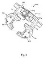
- the length adjustment mechanism 32may include a bar 94 , a first rack 96 , a second rack 98 , a pinion 100 , a biasing member 102 , a stop 104 and an activator 106 .
- the first rack 96 and the second rack 98are integral with the first blade holder 34 and the second blade holder 36 .
- the racks 96 and 98could be portions of a separate length adjustment mechanism as illustrated in U.S. Utility application Ser. No. 12/021,100, entitled “SURGICAL RETRACTOR WITH ADJUSTABLE BLADES AND METHOD OF USE” to Spitler, et al. filed on the same date as this application.
Landscapes
- Health & Medical Sciences (AREA)
- Life Sciences & Earth Sciences (AREA)
- Surgery (AREA)
- Heart & Thoracic Surgery (AREA)
- Engineering & Computer Science (AREA)
- Biomedical Technology (AREA)
- Nuclear Medicine, Radiotherapy & Molecular Imaging (AREA)
- Medical Informatics (AREA)
- Molecular Biology (AREA)
- Animal Behavior & Ethology (AREA)
- General Health & Medical Sciences (AREA)
- Public Health (AREA)
- Veterinary Medicine (AREA)
- Surgical Instruments (AREA)
Abstract
Description
Claims (20)
Priority Applications (1)
| Application Number | Priority Date | Filing Date | Title |
|---|---|---|---|
| US12/021,111US8062217B2 (en) | 2007-01-26 | 2008-01-28 | Surgical retractor with removable blades and method of use |
Applications Claiming Priority (2)
| Application Number | Priority Date | Filing Date | Title |
|---|---|---|---|
| US88670407P | 2007-01-26 | 2007-01-26 | |
| US12/021,111US8062217B2 (en) | 2007-01-26 | 2008-01-28 | Surgical retractor with removable blades and method of use |
Publications (2)
| Publication Number | Publication Date |
|---|---|
| US20080183046A1 US20080183046A1 (en) | 2008-07-31 |
| US8062217B2true US8062217B2 (en) | 2011-11-22 |
Family
ID=40020248
Family Applications (1)
| Application Number | Title | Priority Date | Filing Date |
|---|---|---|---|
| US12/021,111Active2029-10-13US8062217B2 (en) | 2007-01-26 | 2008-01-28 | Surgical retractor with removable blades and method of use |
Country Status (1)
| Country | Link |
|---|---|
| US (1) | US8062217B2 (en) |
Cited By (43)
| Publication number | Priority date | Publication date | Assignee | Title |
|---|---|---|---|---|
| US20100022845A1 (en)* | 2008-07-25 | 2010-01-28 | Ingo Ott | Retractor With Adjustable Blades |
| US20100081885A1 (en)* | 2008-09-30 | 2010-04-01 | Aesculap Implant Systems, Inc. | Tissue retractor system |
| US20100234690A1 (en)* | 2009-03-13 | 2010-09-16 | Cardiolife Research S.A. | Rib retractor |
| US8357184B2 (en) | 2009-11-10 | 2013-01-22 | Nuvasive, Inc. | Method and apparatus for performing spinal surgery |
| US20130046147A1 (en)* | 2011-08-16 | 2013-02-21 | Warsaw Orthopedic, Inc. | Retractor assemblies with blade drive mechanisms |
| US8409091B2 (en) | 2006-09-25 | 2013-04-02 | Spinal Elements, Inc. | Method of using a surgical tissue retractor |
| US8636655B1 (en) | 2010-01-19 | 2014-01-28 | Ronald Childs | Tissue retraction system and related methods |
| US20140114139A1 (en)* | 2012-10-24 | 2014-04-24 | Blackstone Medical, Inc. | Retractor device and method |
| US8727975B1 (en) | 2013-05-10 | 2014-05-20 | Spine Wave, Inc. | Retractor for use in spinal surgery |
| US8900137B1 (en) | 2011-04-26 | 2014-12-02 | Nuvasive, Inc. | Cervical retractor |
| US8974381B1 (en) | 2011-04-26 | 2015-03-10 | Nuvasive, Inc. | Cervical retractor |
| US9028522B1 (en) | 2011-11-15 | 2015-05-12 | Seaspine, Inc. | Tissue dilator and retractor system and method of use |
| US9113853B1 (en) | 2011-08-31 | 2015-08-25 | Nuvasive, Inc. | Systems and methods for performing spine surgery |
| US20150265265A1 (en)* | 2014-03-19 | 2015-09-24 | Warsaw Orthopedic, Inc. | Surgical instrumentation and method |
| US9307972B2 (en) | 2011-05-10 | 2016-04-12 | Nuvasive, Inc. | Method and apparatus for performing spinal fusion surgery |
| US9408596B2 (en) | 2013-03-11 | 2016-08-09 | Spinal Elements, Inc. | Method of using a surgical tissue retractor |
| WO2016144101A1 (en)* | 2015-03-10 | 2016-09-15 | 주식회사 메드릭스 | Rail-type retractor for minimal invasive surgery |
| US20160278755A1 (en)* | 2008-12-18 | 2016-09-29 | Imds | Lateral access system for the lumbar spine |
| US9693761B2 (en) | 2012-10-24 | 2017-07-04 | Blackstone Medical, Inc. | Retractor device and method |
| US20170231614A1 (en) | 2014-09-10 | 2017-08-17 | Spinal Elements, Inc. | Retractor |
| WO2017155718A1 (en)* | 2016-03-09 | 2017-09-14 | Spinal Elements, Inc. | Retractor |
| US9795370B2 (en) | 2014-08-13 | 2017-10-24 | Nuvasive, Inc. | Minimally disruptive retractor and associated methods for spinal surgery |
| US9848864B2 (en) | 2014-05-27 | 2017-12-26 | Kyphon SÀRL | Adjustable cannula and methods of use |
| USD846119S1 (en) | 2017-01-24 | 2019-04-16 | Medtronic Advanced Energy Llc | Lighted surgical retractor base |
| US10736618B2 (en) | 2017-01-24 | 2020-08-11 | Medtronic Advanced Energy Llc | Modular lighted surgical retractor |
| US11166709B2 (en) | 2016-08-23 | 2021-11-09 | Stryker European Operations Holdings Llc | Instrumentation and methods for the implantation of spinal implants |
| US11191532B2 (en) | 2018-03-30 | 2021-12-07 | Stryker European Operations Holdings Llc | Lateral access retractor and core insertion |
| US11224415B1 (en) | 2020-07-10 | 2022-01-18 | Warsaw Orthopedic, Inc. | Tissue retractor |
| US11266391B2 (en) | 2019-02-11 | 2022-03-08 | Warsaw Orthopedic, Inc. | Surgical retractor and method |
| USD956223S1 (en) | 2020-05-12 | 2022-06-28 | Innovasis, Inc. | Surgical retractor |
| USD956225S1 (en) | 2020-05-12 | 2022-06-28 | Innovasis, Inc. | Surgical retractor |
| USD956224S1 (en) | 2020-05-12 | 2022-06-28 | Innovasis, Inc. | Surgical retractor |
| US11413029B2 (en) | 2018-10-24 | 2022-08-16 | Stryker European Operations Holdings Llc | Anterior to psoas instrumentation |
| US11432810B2 (en) | 2020-05-12 | 2022-09-06 | Innovasis, Inc. | Systems and methods for surgical retraction |
| US11464504B2 (en) | 2017-08-17 | 2022-10-11 | Stryker European Operations Holdings Llc | Lateral access bridges, shims and lighting including rod lighting |
| US11564674B2 (en) | 2019-11-27 | 2023-01-31 | K2M, Inc. | Lateral access system and method of use |
| US11583262B2 (en) | 2018-12-18 | 2023-02-21 | DeHeer Orthopedics LLC | Retractor |
| US11701098B2 (en) | 2019-02-11 | 2023-07-18 | Warsaw Orthopedic, Inc. | Surgical retractor system and method |
| US11701097B2 (en) | 2012-07-17 | 2023-07-18 | Warsaw Orthopedic, Inc. | Surgical retractor and method of use |
| US11793504B2 (en) | 2011-08-19 | 2023-10-24 | Nuvasive, Inc. | Surgical retractor system and methods of use |
| US12096923B2 (en) | 2020-07-10 | 2024-09-24 | Warsaw Orthopedic, Inc. | Tissue retractor, retraction modules, and associated methods |
| US12349889B2 (en) | 2020-07-10 | 2025-07-08 | Warsaw Orthopedic, Inc. | Tissue retractor, retraction modules, and associated methods |
| US12383249B2 (en) | 2020-07-10 | 2025-08-12 | Warsaw Orthopedic, Inc. | Tissue retractor, retraction modules, and associated methods |
Families Citing this family (33)
| Publication number | Priority date | Publication date | Assignee | Title |
|---|---|---|---|---|
| US20060095035A1 (en)* | 2004-11-03 | 2006-05-04 | Jones Robert J | Instruments and methods for reduction of vertebral bodies |
| US7931589B2 (en)* | 2006-11-09 | 2011-04-26 | Ebi, Llc | Surgical retractor device and related methods |
| US7922658B2 (en)* | 2006-11-09 | 2011-04-12 | Ebi, Llc | Surgical retractor device and related methods |
| USD626223S1 (en) | 2008-10-22 | 2010-10-26 | Ebi, Llc | Tip portion of a surgical retractor blade |
| AU2009329873A1 (en) | 2008-12-26 | 2011-11-03 | Scott Spann | Minimally-invasive retroperitoneal lateral approach for spinal surgery |
| US8062218B2 (en)* | 2009-02-27 | 2011-11-22 | Warsaw Orthopedic, Inc. | Surgical access instrument |
| US9737288B2 (en)* | 2010-03-11 | 2017-08-22 | Globus Medical, Inc | Tissue retractor and methods of use |
| US9179903B2 (en) | 2010-03-11 | 2015-11-10 | Globus Medical, Inc. | Tissue retractor and method of use |
| US9861273B2 (en) | 2010-03-11 | 2018-01-09 | Globus Medical, Inc. | Tissue retractor and method of use |
| US11998184B2 (en) | 2010-03-11 | 2024-06-04 | Globus Medical, Inc | Tissue retractor and methods of use |
| US11083444B2 (en)* | 2010-03-11 | 2021-08-10 | Globus Medical, Inc. | Tissue retractor and methods of use |
| US8968363B2 (en)* | 2010-03-11 | 2015-03-03 | Globus Medical, Inc. | Tissue retractor and methods of use |
| US8449463B2 (en) | 2010-10-08 | 2013-05-28 | K2M, Inc. | Lateral access system and method of use |
| DE102012100284A1 (en) | 2012-01-13 | 2013-07-18 | Aesculap Ag | Surgical retraction device |
| US9271711B2 (en) | 2012-03-30 | 2016-03-01 | DePuy Synthes Products, Inc. | Methods and devices for tissue retraction |
| DE102013102902A1 (en)* | 2013-03-21 | 2014-09-25 | Aesculap Ag | Surgical retraction device |
| JP6456924B2 (en) | 2013-04-30 | 2019-01-23 | シーダーズ−サイナイ メディカル センター | Fixation device and method for medical procedures |
| US10863976B2 (en)* | 2013-10-07 | 2020-12-15 | Warsaw Orthopedic, Inc. | Spinal implant system and method for lumbar and lumbosacral fusion |
| US9872675B2 (en)* | 2013-12-02 | 2018-01-23 | Thompson Surgical Instruments, Inc. | Surgical retractor with angling device |
| US9999414B2 (en)* | 2014-01-24 | 2018-06-19 | Contour Surgical, Inc. | Retraction devices and methods of its use and manufacture |
| CN107106814B (en) | 2014-10-29 | 2021-02-26 | 西达-赛奈医疗中心 | Apparatus, system and method for controlled delivery of therapeutic agents and related substances |
| US10149674B2 (en) | 2015-08-12 | 2018-12-11 | K2M, Inc. | Orthopedic surgical system including surgical access systems, distraction systems, and methods of using same |
| US10499894B2 (en) | 2015-08-12 | 2019-12-10 | K2M, Inc. | Orthopedic surgical system including surgical access systems, distraction systems, and methods of using same |
| US20190059869A1 (en)* | 2015-10-30 | 2019-02-28 | Cedars-Sinai Medical Center | Tissue retractor systems and methods |
| AU2017235887B2 (en) | 2016-09-26 | 2021-09-30 | K2M, Inc. | Retraction system and method of use |
| US10898175B2 (en) | 2016-10-04 | 2021-01-26 | Jgmg Bengochea, Llc | Retractor extension clip systems |
| US10716553B2 (en) | 2017-04-19 | 2020-07-21 | Pantheon Spinal, Llc | Spine surgery retractor system and related methods |
| WO2019236027A2 (en)* | 2018-02-21 | 2019-12-12 | Orhan Seyfi Aksakal | A retractor system |
| RU2698297C1 (en)* | 2018-12-26 | 2019-08-23 | Ооо "Титанмед" | Retractor for spine surgery |
| US11375989B2 (en) | 2019-12-10 | 2022-07-05 | Thompson Surgical Instruments, Inc. | Retractor system, swivel lock, and surgical retractor blade |
| CN112957087B (en)* | 2021-05-19 | 2021-08-10 | 上海宇度医学科技股份有限公司 | Laparoscopic surgery retractor, laparoscopic surgery tissue taking-out assembly and taking-out method |
| US20230035781A1 (en)* | 2021-07-30 | 2023-02-02 | Seaspine, Inc. | Retractor Tool Apparatus and Method of Manipulation |
| US20240197310A1 (en)* | 2022-12-14 | 2024-06-20 | Thompson Surgical Instruments, Inc. | Surgical retractor with integrated handle and system |
Citations (237)
| Publication number | Priority date | Publication date | Assignee | Title |
|---|---|---|---|---|
| US458457A (en) | 1891-08-25 | Vaginal syringe | ||
| US643221A (en) | 1899-08-12 | 1900-02-13 | Lee J Chapman | Douching-speculum. |
| US708452A (en) | 1902-07-01 | 1902-09-02 | Ernst Beist | Dilator. |
| US823409A (en) | 1905-12-18 | 1906-06-12 | L D Winters | Vaginal irrigator. |
| US891091A (en) | 1908-01-29 | 1908-06-16 | Charles Mouthuy | Woodworker's clamp. |
| US942523A (en) | 1909-10-20 | 1909-12-07 | Ind Dev & Mfg Co | Irrigating-syringe. |
| US983871A (en) | 1909-03-27 | 1911-02-14 | Joseph J Brin | Syringe. |
| US1275520A (en) | 1917-06-14 | 1918-08-13 | William L Bell | Gauze-dam surgical instrument. |
| US1359164A (en) | 1919-11-28 | 1920-11-16 | Giudice Filippo Lo | Surgical instrument |
| US1412976A (en) | 1921-03-14 | 1922-04-18 | Frederick W Stanton | Syringe |
| US1538032A (en) | 1921-12-03 | 1925-05-19 | Fischer Hans | Surgical injector |
| US1613141A (en) | 1923-05-26 | 1927-01-04 | Herbert E Stein | Surgical retractor instrument |
| US1659112A (en) | 1927-05-12 | 1928-02-14 | Dana M Littlejohn | Toggle-squeeze hemostat forceps |
| US2109147A (en) | 1937-05-27 | 1938-02-22 | Patrick P Grosso | Adjustable angle surgical instrument |
| US2507710A (en) | 1949-07-02 | 1950-05-16 | Patrick P Grosso | Adjustable-angle surgical instrument |
| US2579849A (en) | 1946-01-26 | 1951-12-25 | Louis B Newman | Surgical speculum |
| US2693795A (en) | 1950-09-09 | 1954-11-09 | Herman R Grieshaber | Surgical retractor |
| US3030947A (en) | 1960-05-16 | 1962-04-24 | Richard M Engelbert | Speculum |
| US3039462A (en) | 1959-03-06 | 1962-06-19 | Henry W Walden | Device for dilating and dispensing material to body cavities |
| US3054398A (en) | 1961-02-13 | 1962-09-18 | Arnold J Kobler | Eyelid spreader |
| US3528409A (en) | 1968-01-29 | 1970-09-15 | Samuel M Bruder | Disposable medical spectrum |
| US3568665A (en) | 1967-10-20 | 1971-03-09 | Sture Lindgren | Speculum for examination of cavity |
| US3702606A (en) | 1970-04-21 | 1972-11-14 | Rancray Ltd | Speculum |
| US3716047A (en) | 1970-12-21 | 1973-02-13 | Welch Allyn Inc | Disposable light-conductive speculum |
| US3747591A (en) | 1971-03-11 | 1973-07-24 | B Golden | Vaginal speculum |
| US3749088A (en) | 1971-06-23 | 1973-07-31 | W Kohlmann | Surgical retractor device |
| US3807393A (en) | 1972-03-01 | 1974-04-30 | Donald B Mc | Surgical retractor |
| US3847143A (en) | 1973-05-01 | 1974-11-12 | Medspecs Inc | Speculum |
| US3893454A (en) | 1973-12-04 | 1975-07-08 | Stille Werner Ab | Instrument for use in coniotomy |
| US4010740A (en) | 1975-04-21 | 1977-03-08 | Abm-Mavello Ab | Speculum |
| US4025053A (en) | 1976-05-10 | 1977-05-24 | Stickle Jr Warren Edward | Screw actuated scissor jack with a self adjusting bearing surface |
| US4206750A (en) | 1977-12-15 | 1980-06-10 | Seppo Kaivola | Speculum for gynecological endoscopy examination |
| US4263899A (en) | 1978-05-01 | 1981-04-28 | Burgin Kermit H | Locking adjustable speculum |
| US4432351A (en) | 1980-06-26 | 1984-02-21 | Institute For Industrial Research And Standards | Vaginal speculum |
| US4496345A (en) | 1982-08-30 | 1985-01-29 | Hasson Harrith M | Ballooned cannula |
| US4545374A (en) | 1982-09-03 | 1985-10-08 | Jacobson Robert E | Method and instruments for performing a percutaneous lumbar diskectomy |
| US4562832A (en) | 1984-01-21 | 1986-01-07 | Wilder Joseph R | Medical instrument and light pipe illumination assembly |
| US4592344A (en) | 1980-07-25 | 1986-06-03 | Scheer Peter M | Combination illuminator and lip and cheek expander |
| US4597383A (en) | 1985-04-25 | 1986-07-01 | Luxtec Corporation | Fiber-optic illuminated vaginal speculum |
| US4616635A (en) | 1984-04-04 | 1986-10-14 | Aesculap-Werke Aktiengesellschaft | Surgical instrument for the splaying of wound edges |
| US4627421A (en) | 1984-08-03 | 1986-12-09 | Symbas Panagiotis N | Sternal retractor |
| US4648388A (en) | 1985-11-01 | 1987-03-10 | Acromed Corporation | Apparatus and method for maintaining vertebrae in a desired relationship |
| US4674501A (en) | 1986-04-14 | 1987-06-23 | Greenberg I Melbourne | Surgical instrument |
| US4765311A (en) | 1986-04-24 | 1988-08-23 | Kulik Yaroslav P | Wound retractor |
| US4852552A (en) | 1987-09-03 | 1989-08-01 | Pilling Co. | Sternal retractor |
| US4899729A (en) | 1985-05-30 | 1990-02-13 | Gill Steven S | Expansible cannula |
| US4905670A (en) | 1988-12-28 | 1990-03-06 | Adair Edwin Lloyd | Apparatus for cervical videoscopy |
| US4926849A (en) | 1986-12-19 | 1990-05-22 | Downey Ernest L | Apparatus for separating vertebrae |
| US4945896A (en) | 1989-01-24 | 1990-08-07 | Gade George F | Surgical retractor assembly having tissue viability sensor embedded therein |
| US4957495A (en) | 1987-04-01 | 1990-09-18 | Patrick Kluger | Device for setting the spinal column |
| US5052373A (en) | 1988-07-29 | 1991-10-01 | Michelson Gary K | Spinal retractor |
| US5054906A (en) | 1986-01-17 | 1991-10-08 | Brimfield Precision, Inc. | Indirectly illuminating ophthalmological speculum |
| US5125396A (en) | 1990-10-05 | 1992-06-30 | Ray R Charles | Surgical retractor |
| US5139511A (en) | 1990-02-14 | 1992-08-18 | Gill Steven S | Expansible cannula |
| US5167662A (en) | 1992-01-24 | 1992-12-01 | Zimmer, Inc. | Temporary clamp and inserter for a posterior midline spinal clamp |
| US5183464A (en) | 1991-05-17 | 1993-02-02 | Interventional Thermodynamics, Inc. | Radially expandable dilator |
| US5195507A (en) | 1990-11-06 | 1993-03-23 | Ethicon, Inc. | Endoscopic surgical instrument for displacing tissue or organs |
| US5234460A (en) | 1992-06-24 | 1993-08-10 | Stouder Jr Albert E | Laparoscopy instrument |
| US5297538A (en) | 1992-04-10 | 1994-03-29 | Daniel Elie C | Surgical retractor/compressor |
| US5312417A (en) | 1992-07-29 | 1994-05-17 | Wilk Peter J | Laparoscopic cannula assembly and associated method |
| US5320611A (en) | 1993-02-04 | 1994-06-14 | Peter M. Bonutti | Expandable cannula having longitudinal wire and method of use |
| US5331975A (en) | 1990-03-02 | 1994-07-26 | Bonutti Peter M | Fluid operated retractors |
| US5339801A (en) | 1992-03-12 | 1994-08-23 | Uresil Corporation | Surgical retractor and surgical method |
| US5339803A (en) | 1993-04-13 | 1994-08-23 | Ilya Mayzels | Self-hinging disposable retractor instrument for endoscopic surgery |
| US5342385A (en) | 1991-02-05 | 1994-08-30 | Norelli Robert A | Fluid-expandable surgical retractor |
| US5363841A (en) | 1993-07-02 | 1994-11-15 | Coker Wesley L | Retractor for spinal surgery |
| US5377667A (en) | 1992-12-03 | 1995-01-03 | Michael T. Patton | Speculum for dilating a body cavity |
| US5395303A (en) | 1990-07-30 | 1995-03-07 | Peter M. Bonutti | Orthosis with distraction through range of motion |
| US5423826A (en) | 1993-02-05 | 1995-06-13 | Danek Medical, Inc. | Anterior cervical plate holder/drill guide and method of use |
| US5431658A (en) | 1994-02-14 | 1995-07-11 | Moskovich; Ronald | Facilitator for vertebrae grafts and prostheses |
| US5484437A (en) | 1988-06-13 | 1996-01-16 | Michelson; Gary K. | Apparatus and method of inserting spinal implants |
| US5496345A (en) | 1992-06-02 | 1996-03-05 | General Surgical Innovations, Inc. | Expansible tunneling apparatus for creating an anatomic working space |
| US5503617A (en) | 1994-07-19 | 1996-04-02 | Jako; Geza J. | Retractor and method for direct access endoscopic surgery |
| US5509893A (en) | 1991-06-06 | 1996-04-23 | Meditech International Pty Ltd. | Speculum |
| US5514076A (en) | 1994-01-27 | 1996-05-07 | Flexmedics Corporation | Surgical retractor |
| US5520611A (en) | 1993-12-16 | 1996-05-28 | Rao; Shekar | Illuminated retractor |
| US5540711A (en) | 1992-06-02 | 1996-07-30 | General Surgical Innovations, Inc. | Apparatus and method for developing an anatomic space for laparoscopic procedures with laparoscopic visualization |
| US5700263A (en) | 1996-06-17 | 1997-12-23 | Schendel; Stephen A. | Bone distraction apparatus |
| US5704937A (en) | 1993-08-27 | 1998-01-06 | Paulette Fairant | Operative equipment for fixing spinal instrumentation |
| US5704904A (en) | 1995-06-07 | 1998-01-06 | Antigee Advantage International, Inc. | Inflatable lumber traction vest |
| US5707359A (en) | 1995-11-14 | 1998-01-13 | Bufalini; Bruno | Expanding trocar assembly |
| US5720746A (en) | 1994-11-16 | 1998-02-24 | Soubeiran; Arnaud Andre | Device for displacing two bodies relative to each other |
| US5720748A (en) | 1993-02-10 | 1998-02-24 | Spine-Tech, Inc. | Spinal stabilization surgical apparatus |
| US5724993A (en) | 1995-06-07 | 1998-03-10 | Antigee Advantage International, Inc. | Inflatable spinal traction device |
| US5776054A (en) | 1996-08-07 | 1998-07-07 | Bobra; Dilip | Apparatus for retracting tissue |
| US5782753A (en) | 1995-10-20 | 1998-07-21 | United States Surgical Corporation | Surgical retractor |
| US5797909A (en) | 1988-06-13 | 1998-08-25 | Michelson; Gary Karlin | Apparatus for inserting spinal implants |
| US5899854A (en) | 1998-04-20 | 1999-05-04 | University Of New Mexico | Speculum and method for inserting an elongated instrument into an animal's body |
| US5899901A (en) | 1991-05-18 | 1999-05-04 | Middleton; Jeffrey Keith | Spinal fixation system |
| US5902233A (en) | 1996-12-13 | 1999-05-11 | Thompson Surgical Instruments, Inc. | Angling surgical retractor apparatus and method of retracting anatomy |
| US5910155A (en) | 1998-06-05 | 1999-06-08 | United States Surgical Corporation | Vascular wound closure system |
| US5928139A (en) | 1998-04-24 | 1999-07-27 | Koros; Tibor B. | Retractor with adjustable length blades and light pipe guides |
| US5931777A (en) | 1998-03-11 | 1999-08-03 | Sava; Gerard A. | Tissue retractor and method for use |
| US5944658A (en) | 1997-09-23 | 1999-08-31 | Koros; Tibor B. | Lumbar spinal fusion retractor and distractor system |
| US5950628A (en) | 1995-12-29 | 1999-09-14 | Kinesis Medical, Inc. | Inflatable wearable traction device |
| US5957836A (en) | 1998-10-16 | 1999-09-28 | Johnson; Lanny L. | Rotatable retractor |
| US5957902A (en) | 1998-09-28 | 1999-09-28 | Teves; Leonides Y. | Surgical tool for enlarging puncture opening made by trocar |
| US5964780A (en) | 1995-10-06 | 1999-10-12 | Deutsche Forschungsanstalt Fur Luft-Und Raumfahrt E.V. | Gripping apparatus for use in minimally-invasive surgery |
| US6007487A (en) | 1996-03-22 | 1999-12-28 | Sdgi Holdings, Inc. | Tissue retractor for use through a cannula |
| US6017342A (en) | 1998-08-05 | 2000-01-25 | Beere Precision Medical Instrumnets, Inc. | Compression and distraction instrument |
| US6074343A (en) | 1999-04-16 | 2000-06-13 | Nathanson; Michael | Surgical tissue retractor |
| US6090041A (en) | 1999-02-16 | 2000-07-18 | Regents Of The University Of California | vacuum actuated surgical retractor and methods |
| US6099468A (en) | 1999-01-15 | 2000-08-08 | Kapp Surgical Instrument, Inc. | Retractor for partial sternotomy |
| US6142935A (en) | 1996-03-04 | 2000-11-07 | Heartport, Inc. | Illuminating soft tissue retractor |
| US6171299B1 (en) | 1990-03-02 | 2001-01-09 | General Surgical Innovations, Inc. | Method of providing surgical access through an incision |
| US6187000B1 (en) | 1998-08-20 | 2001-02-13 | Endius Incorporated | Cannula for receiving surgical instruments |
| US6196968B1 (en) | 1997-06-02 | 2001-03-06 | General Surgical Innovations, Inc. | Direct vision subcutaneous tissue retractor and method for use |
| US6214004B1 (en) | 1998-06-09 | 2001-04-10 | Wesley L. Coker | Vertebral triplaner alignment facilitator |
| US6226548B1 (en) | 1997-09-24 | 2001-05-01 | Surgical Navigation Technologies, Inc. | Percutaneous registration apparatus and method for use in computer-assisted surgical navigation |
| US6224545B1 (en) | 1998-07-24 | 2001-05-01 | Core Surgical, Inc. | Surgical retractor and method for use |
| US6261296B1 (en) | 1998-10-02 | 2001-07-17 | Synthes U.S.A. | Spinal disc space distractor |
| US6340363B1 (en) | 1998-10-09 | 2002-01-22 | Surgical Navigation Technologies, Inc. | Image guided vertebral distractor and method for tracking the position of vertebrae |
| US6350236B1 (en) | 1998-05-01 | 2002-02-26 | Genzyme Corporation | Illuminated saphenous vein retractor |
| US6354995B1 (en) | 1998-04-24 | 2002-03-12 | Moshe Hoftman | Rotational lateral expander device |
| US6364832B1 (en) | 1999-12-23 | 2002-04-02 | Tri-State Hospital Supply Corporation | Vaginal lateral walls retractor for use in combination with vaginal specula and method of performing vaginal/cervical examination |
| US6379296B1 (en) | 1999-03-26 | 2002-04-30 | Richard W. Baggett | Medical lighting device |
| US6416470B2 (en) | 1998-06-26 | 2002-07-09 | Coroneo, Inc. | Surgical retractor having low-friction actuating means and contoured blade arms |
| US6428473B1 (en) | 2000-02-18 | 2002-08-06 | Genzyme Corporation | Illuminated rectal retractor |
| US6488620B1 (en) | 1998-04-13 | 2002-12-03 | Viamedics, Llc | Self-seating surgical access device |
| US6497654B1 (en) | 2000-02-18 | 2002-12-24 | Genzyme Corporation | Illuminated rectal retractor |
| US6504985B2 (en) | 1995-06-27 | 2003-01-07 | Lumitex, Inc. | Illuminated surgical retractor |
| US6530926B1 (en) | 2000-08-01 | 2003-03-11 | Endius Incorporated | Method of securing vertebrae |
| US6551316B1 (en) | 2001-03-02 | 2003-04-22 | Beere Precision Medical Instruments, Inc. | Selective compression and distraction instrument |
| US6554768B1 (en) | 2000-09-05 | 2003-04-29 | Genzyme Corporation | Illuminated deep pelvic retractor |
| US6564078B1 (en) | 1998-12-23 | 2003-05-13 | Nuvasive, Inc. | Nerve surveillance cannula systems |
| US6565574B2 (en) | 1999-01-25 | 2003-05-20 | Gary K. Michelson | Distractor for use in spinal surgery |
| US6569168B2 (en) | 2000-05-05 | 2003-05-27 | Osteotech, Inc. | Intervertebral distractor and implant insertion instrument |
| US20030191371A1 (en) | 2002-04-05 | 2003-10-09 | Smith Maurice M. | Devices and methods for percutaneous tissue retraction and surgery |
| US6702741B2 (en) | 1998-04-23 | 2004-03-09 | Scimed Life Systems, Inc. | Medical body access device |
| US6712795B1 (en) | 2002-06-07 | 2004-03-30 | Lester Cohen | Surgical procedure and apparatus |
| US6723044B2 (en) | 2002-03-14 | 2004-04-20 | Apple Medical Corporation | Abdominal retractor |
| US20040093001A1 (en) | 2002-10-25 | 2004-05-13 | Hamada James S. | Minimal access lumbar diskectomy instrumentation and method |
| US6739744B2 (en) | 1997-07-02 | 2004-05-25 | Lumitex, Inc. | Light delivery systems and applications thereof |
| US6761723B2 (en) | 2002-01-14 | 2004-07-13 | Dynamic Spine, Inc. | Apparatus and method for performing spinal surgery |
| US20040176665A1 (en) | 2002-06-26 | 2004-09-09 | Branch Charles L. | Instruments and methods for minimally invasive tissue retraction and surgery |
| US20040193018A1 (en) | 2003-03-31 | 2004-09-30 | Depuy Acromed | Surgical retractor |
| US6805666B2 (en) | 2002-05-23 | 2004-10-19 | Donna D. Holland | Pivotal and illuminated saphenous vein retractor with tapered design |
| US6817978B2 (en) | 2002-01-23 | 2004-11-16 | Teleflex-Ct Devices Incorporated | Illuminated retractor for use in connection with harvesting a blood vessel from the arm |
| US20040230100A1 (en) | 2003-05-16 | 2004-11-18 | Shluzas Alan E. | Access device for minimally invasive surgery |
| US6837851B1 (en) | 1999-10-18 | 2005-01-04 | Coroneo, Inc. | Adjustable surgical retractor |
| US6869398B2 (en) | 2003-01-06 | 2005-03-22 | Theodore G. Obenchain | Four-blade surgical speculum |
| US20050070765A1 (en) | 2003-09-18 | 2005-03-31 | Howmedica Osteonics Corp. | Surgical retractor with removable scissor arms |
| US20050075540A1 (en) | 2003-08-26 | 2005-04-07 | Shluzas Alan E. | Minimally invasive access device and method |
| US6887255B2 (en) | 2002-04-19 | 2005-05-03 | Peter Shimm | Laparoscopic specimen extraction port |
| US20050137461A1 (en) | 2003-12-18 | 2005-06-23 | Depuy Spine, Inc. | Telescoping blade assembly and instruments for adjusting an adjustable blade |
| US20050159651A1 (en) | 2003-12-18 | 2005-07-21 | Depuy Spine, Inc. | Surgical retractor systems and illuminated cannulae |
| US6929606B2 (en) | 2001-01-29 | 2005-08-16 | Depuy Spine, Inc. | Retractor and method for spinal pedicle screw placement |
| US6932764B2 (en) | 2001-11-20 | 2005-08-23 | Ravindra Kashyap | Multipurpose circular retractor |
| US20050215862A1 (en) | 2003-11-26 | 2005-09-29 | Jeffrey Larson | Guided retractor and methods of use |
| US20050234304A1 (en) | 2002-06-26 | 2005-10-20 | Sdgi Holdings, Inc. | Instruments and methods for minimally invasive tissue retraction and surgery |
| US20050267336A1 (en) | 1996-04-10 | 2005-12-01 | Bertolero Arthur A | Surgical retractor and stabilizing device and method for use |
| US20050277812A1 (en) | 2004-06-14 | 2005-12-15 | Myles Robert T | Minimally invasive surgical spinal exposure system |
| US7014608B2 (en) | 2002-12-13 | 2006-03-21 | Synthes Spine Company, Lp | Guided retractor and methods of use |
| US20060074445A1 (en) | 2004-09-29 | 2006-04-06 | David Gerber | Less invasive surgical system and methods |
| US20060074278A1 (en) | 2004-09-02 | 2006-04-06 | Dominique Petit | Tissue retractor producing a widened operating channel |
| US20060084981A1 (en) | 2004-10-20 | 2006-04-20 | Endius Incorporated | Apparatus for connecting a longitudinal member to a bone portion |
| US20060089536A1 (en) | 2004-10-26 | 2006-04-27 | U.S. Spinal Technologies, Llc | Expandable surgical retractor system for minimal access surgery |
| US20060089652A1 (en) | 2004-10-26 | 2006-04-27 | Concept Matrix, Llc | Working channel for minimally invasive spine surgery |
| US20060100487A1 (en) | 1997-09-30 | 2006-05-11 | Raymond Cartier | Surgical retractor with mounting rail |
| US20060106416A1 (en) | 2004-10-29 | 2006-05-18 | Douglas Raymond | Expandable ports and methods for minimally invasive surgery |
| US7056321B2 (en) | 2000-08-01 | 2006-06-06 | Endius, Incorporated | Method of securing vertebrae |
| US20060142642A1 (en) | 2004-12-29 | 2006-06-29 | Lins Robert E | Minimally-invasive portal system for performing lumbar decompression, instrumented fusion/stabilization, and the like |
| US20060142643A1 (en) | 2004-12-23 | 2006-06-29 | Brad Parker | Radially expanding surgical retractor |
| US20060155170A1 (en) | 2002-12-13 | 2006-07-13 | Synthes Spine Company, Lp | Guided retractor and methods of use |
| US7079883B2 (en) | 1998-12-23 | 2006-07-18 | Nuvaslve, Inc. | Nerve surveillance cannulae systems |
| US20060167487A1 (en) | 2002-10-25 | 2006-07-27 | Hamada James S | Minimal access lumbar diskectomy instrumentation and method |
| US20060178693A1 (en) | 2002-10-25 | 2006-08-10 | Hamada James S | Minimal access lumbar diskectomy instrumentation and method |
| US20060195017A1 (en) | 2004-11-22 | 2006-08-31 | Shluzas Alan E | Expandable device for providing access to the spine |
| US20060200189A1 (en) | 2003-12-05 | 2006-09-07 | Nance Edward J | Expandable percutaneous sheath |
| US20060200186A1 (en) | 2005-03-04 | 2006-09-07 | Marchek Connie P | Adjustable access device for surgical procedures |
| US20060206008A1 (en) | 2005-03-09 | 2006-09-14 | Dalton Brian E | Retractor and method for percutaneous tissue retraction and surgery |
| US7108698B2 (en) | 2004-01-13 | 2006-09-19 | Zimmer Spine, Inc. | Combined distractor and retractor instrument and methods |
| US20060217596A1 (en) | 1997-07-02 | 2006-09-28 | Lumitex, Inc. | Illuminated surgical retractor |
| US20060224044A1 (en) | 2005-03-31 | 2006-10-05 | Depuy Spine, Inc. | Surgical retractors and methods of use |
| US20060229636A1 (en) | 2005-03-04 | 2006-10-12 | Woodburn William N Sr | Expandable access device with mobility member |
| US20060235279A1 (en) | 2005-03-18 | 2006-10-19 | Hawkes David T | Less invasive access port system and method for using the same |
| US20060241350A1 (en) | 2005-04-22 | 2006-10-26 | Sdgi Holdings, Inc. | Instruments and methods for selective tissue retraction through a retractor sleeve |
| US20060247651A1 (en) | 2002-09-19 | 2006-11-02 | Roehm Thomas E Iii | Oval dilator and retractor set and method |
| US20060264968A1 (en) | 1999-10-21 | 2006-11-23 | George Frey | Devices and techniques for a posterior lateral disc space approach |
| US20060271096A1 (en) | 2002-10-25 | 2006-11-30 | Hamada James S | Minimal incision maximal access MIS spine instrumentation and method |
| US20060287584A1 (en) | 2005-06-16 | 2006-12-21 | Javier Garcia-Bengochia | Surgical retractor extensions |
| US20070010716A1 (en) | 2005-07-11 | 2007-01-11 | Malandain Hugues F | Surgical access device, system, and methods of use |
| US7163510B2 (en) | 2003-09-17 | 2007-01-16 | Applied Medical Resources Corporation | Surgical instrument access device |
| US7166073B2 (en) | 2000-09-29 | 2007-01-23 | Stephen Ritland | Method and device for microsurgical intermuscular spinal surgery |
| US20070027364A1 (en) | 2005-07-28 | 2007-02-01 | Stefan Schwer | Expandable access device |
| US20070038034A1 (en) | 2005-08-15 | 2007-02-15 | Sweeney Thomas M Ii | Systems and methods for performing percutaneous surgery |
| US20070038033A1 (en) | 2005-04-25 | 2007-02-15 | Depuy Spine, Inc. | Cassette based surgical retractor |
| US20070038216A1 (en) | 2002-10-25 | 2007-02-15 | Hamada James S | Minimal incision maximal access MIS spine instrumentation and method |
| US20070038032A1 (en) | 2005-08-11 | 2007-02-15 | Cardio Life Research S.A. | Surgical retractor |
| US7179225B2 (en) | 2003-08-26 | 2007-02-20 | Shluzas Alan E | Access systems and methods for minimally invasive surgery |
| US7182730B2 (en) | 2004-03-12 | 2007-02-27 | Fehling Ag | Anal retractor |
| US7189244B2 (en) | 2002-08-02 | 2007-03-13 | Depuy Spine, Inc. | Compressor for use in minimally invasive surgery |
| US20070060795A1 (en) | 2005-09-14 | 2007-03-15 | Spotlight Surgical, Inc. | Lighted surgical retractors with LED illumination light engines |
| US20070060793A1 (en) | 2005-08-30 | 2007-03-15 | Degould Michael D | Suction retraction instrument for surgery |
| US7195592B2 (en) | 2004-01-27 | 2007-03-27 | Sundaram Ravikumar | Surgical retractor apparatus for use with a surgical port |
| US7207949B2 (en) | 2003-09-25 | 2007-04-24 | Nuvasive, Inc. | Surgical access system and related methods |
| US7210485B2 (en) | 2002-08-01 | 2007-05-01 | C & J Holdings, Llc | Method for spinal surgery |
| US20070100212A1 (en) | 2004-10-08 | 2007-05-03 | Nuvasive, Inc. | Surgical access system and related methods |
| US20070100366A1 (en) | 2005-10-28 | 2007-05-03 | Sara Dziedzic | Minimally invasive tissue expander systems and methods |
| US20070106123A1 (en) | 2005-09-26 | 2007-05-10 | Josef Gorek | Minimally invasive retractor and methods of use |
| US20070118022A1 (en) | 2005-10-07 | 2007-05-24 | Alphatec Spine, Inc. | Retractor and methods of use |
| US20070118170A1 (en) | 1992-06-02 | 2007-05-24 | General Surgical Innovations, Inc. | Apparatus and method for dissecting tissue layers |
| US20070129608A1 (en) | 2005-12-07 | 2007-06-07 | Sandhu Faheem A | Access system for minimally invasive spinal surgery |
| US7229408B2 (en) | 2004-06-30 | 2007-06-12 | Ethicon, Inc. | Low profile surgical retractor |
| US7238154B2 (en) | 2001-10-20 | 2007-07-03 | Applied Medical Resources Corporation | Wound retraction apparatus and method |
| US7238155B2 (en) | 1999-05-04 | 2007-07-03 | Cardiothoracic Systems, Inc. | Method and apparatus for creating a working opening through an incision |
| US20070156023A1 (en) | 2006-01-05 | 2007-07-05 | Depuy Spine, Inc. | Non-rigid surgical retractor |
| US20070156027A1 (en) | 1999-05-04 | 2007-07-05 | Hu Lawrence W | Surgical retractor platform blade apparatus |
| US20070156025A1 (en) | 2006-01-04 | 2007-07-05 | Connie Marchek | Surgical retractors and methods of minimally invasive surgery |
| US20070156024A1 (en) | 2006-01-04 | 2007-07-05 | William Frasier | Surgical Retractors and Methods of Minimally Invasive Surgery |
| US20070156026A1 (en) | 2006-01-04 | 2007-07-05 | William Frasier | Surgical access devices and methods of minimally invasive surgery |
| US20070161864A1 (en) | 2006-01-09 | 2007-07-12 | Sloan Dale A | Laparoscopic Tissue Retractor |
| US20070161865A1 (en) | 2006-01-11 | 2007-07-12 | Mehdi Fakhrai | Retractor |
| US20070158513A1 (en) | 2006-01-12 | 2007-07-12 | Levahn Intellectual Property Holding Company, Llc | Surgical clamp and tool support system |
| US20070179343A1 (en) | 2006-01-30 | 2007-08-02 | Shelokov Alexis P | Suction retraction surgical instrument |
| US20070203399A1 (en) | 2006-01-23 | 2007-08-30 | Gephart Matthew P | Retraction Apparatus and Method of Use |
| US20070208228A1 (en) | 2006-03-01 | 2007-09-06 | Nicholas Pavento | Surgical retractors and methods of minimally invasive surgery |
| US20070208226A1 (en) | 2006-01-18 | 2007-09-06 | Spotlight Surgical, Inc. | Retractor illumination system |
| US20070208229A1 (en) | 2006-03-02 | 2007-09-06 | Prusmack Chad J | Method and apparatus for minimally invasive spine surgery |
| US20070208227A1 (en) | 2002-07-11 | 2007-09-06 | Nuvasive, Inc. | Surgical access system and related methods |
| US20070213596A1 (en) | 2006-02-07 | 2007-09-13 | Hamada James S | Minimal incision maximal access spine surgery instruments and method |
| US20070225568A1 (en) | 2006-03-22 | 2007-09-27 | Dennis Colleran | Surgical retractor device and method of use |
| US20070225571A1 (en) | 2002-08-02 | 2007-09-27 | Branch Charles L | Systems and techniques for illuminating a surgical space |
| US20070238932A1 (en) | 2006-03-08 | 2007-10-11 | Jones Robert J | Surgical retractor and retractor assembly |
| US20070260125A1 (en) | 2006-05-02 | 2007-11-08 | Strauss Kevin R | Minimally open retraction device |
| US20070276191A1 (en) | 2006-05-26 | 2007-11-29 | Sean Selover | Illuminated surgical access system including a surgical access device and integrated light emitter |
| US20070293729A1 (en) | 2006-05-26 | 2007-12-20 | Spotlight Surgical, Inc. | Blade insert illuminator |
| US20080002426A1 (en) | 2006-06-13 | 2008-01-03 | Spotlight Surgical, Inc. | Film illumination system |
| US20080021284A1 (en) | 2006-07-19 | 2008-01-24 | Zimmer Spine, Inc. | Surgical access system and method of using the same |
| US20080058606A1 (en) | 2002-10-08 | 2008-03-06 | Nuvasive, Inc. | Surgical access system and related methods |
| US20080086114A1 (en) | 2006-08-29 | 2008-04-10 | Baxano, Inc. | Tissue Access Guidewire System and Method |
| US7371213B2 (en) | 2003-01-31 | 2008-05-13 | Zimmer Technology, Inc. | Lit retractor |
| US20080132766A1 (en) | 2006-12-05 | 2008-06-05 | Zimmer Spine, Inc. | Surgical Access System And Method Of Using Same |
| US20080255563A1 (en) | 2006-11-03 | 2008-10-16 | Innovative Spine | Instrumentation and method for providing surgical access to a spine |
| US20090124860A1 (en) | 2003-02-27 | 2009-05-14 | Nuvasive, Inc. | Surgical access system and related methods |
| US7582058B1 (en) | 2002-06-26 | 2009-09-01 | Nuvasive, Inc. | Surgical access system and related methods |
| US7691057B2 (en) | 2003-01-16 | 2010-04-06 | Nuvasive, Inc. | Surgical access system and related methods |
- 2008
- 2008-01-28USUS12/021,111patent/US8062217B2/enactiveActive
Patent Citations (289)
| Publication number | Priority date | Publication date | Assignee | Title |
|---|---|---|---|---|
| US458457A (en) | 1891-08-25 | Vaginal syringe | ||
| US643221A (en) | 1899-08-12 | 1900-02-13 | Lee J Chapman | Douching-speculum. |
| US708452A (en) | 1902-07-01 | 1902-09-02 | Ernst Beist | Dilator. |
| US823409A (en) | 1905-12-18 | 1906-06-12 | L D Winters | Vaginal irrigator. |
| US891091A (en) | 1908-01-29 | 1908-06-16 | Charles Mouthuy | Woodworker's clamp. |
| US983871A (en) | 1909-03-27 | 1911-02-14 | Joseph J Brin | Syringe. |
| US942523A (en) | 1909-10-20 | 1909-12-07 | Ind Dev & Mfg Co | Irrigating-syringe. |
| US1275520A (en) | 1917-06-14 | 1918-08-13 | William L Bell | Gauze-dam surgical instrument. |
| US1359164A (en) | 1919-11-28 | 1920-11-16 | Giudice Filippo Lo | Surgical instrument |
| US1412976A (en) | 1921-03-14 | 1922-04-18 | Frederick W Stanton | Syringe |
| US1538032A (en) | 1921-12-03 | 1925-05-19 | Fischer Hans | Surgical injector |
| US1613141A (en) | 1923-05-26 | 1927-01-04 | Herbert E Stein | Surgical retractor instrument |
| US1659112A (en) | 1927-05-12 | 1928-02-14 | Dana M Littlejohn | Toggle-squeeze hemostat forceps |
| US2109147A (en) | 1937-05-27 | 1938-02-22 | Patrick P Grosso | Adjustable angle surgical instrument |
| US2579849A (en) | 1946-01-26 | 1951-12-25 | Louis B Newman | Surgical speculum |
| US2507710A (en) | 1949-07-02 | 1950-05-16 | Patrick P Grosso | Adjustable-angle surgical instrument |
| US2693795A (en) | 1950-09-09 | 1954-11-09 | Herman R Grieshaber | Surgical retractor |
| US3039462A (en) | 1959-03-06 | 1962-06-19 | Henry W Walden | Device for dilating and dispensing material to body cavities |
| US3030947A (en) | 1960-05-16 | 1962-04-24 | Richard M Engelbert | Speculum |
| US3054398A (en) | 1961-02-13 | 1962-09-18 | Arnold J Kobler | Eyelid spreader |
| US3568665A (en) | 1967-10-20 | 1971-03-09 | Sture Lindgren | Speculum for examination of cavity |
| US3528409A (en) | 1968-01-29 | 1970-09-15 | Samuel M Bruder | Disposable medical spectrum |
| US3702606A (en) | 1970-04-21 | 1972-11-14 | Rancray Ltd | Speculum |
| US3716047A (en) | 1970-12-21 | 1973-02-13 | Welch Allyn Inc | Disposable light-conductive speculum |
| US3747591A (en) | 1971-03-11 | 1973-07-24 | B Golden | Vaginal speculum |
| US3749088A (en) | 1971-06-23 | 1973-07-31 | W Kohlmann | Surgical retractor device |
| US3807393A (en) | 1972-03-01 | 1974-04-30 | Donald B Mc | Surgical retractor |
| US3847143A (en) | 1973-05-01 | 1974-11-12 | Medspecs Inc | Speculum |
| US3893454A (en) | 1973-12-04 | 1975-07-08 | Stille Werner Ab | Instrument for use in coniotomy |
| US4010740A (en) | 1975-04-21 | 1977-03-08 | Abm-Mavello Ab | Speculum |
| US4025053A (en) | 1976-05-10 | 1977-05-24 | Stickle Jr Warren Edward | Screw actuated scissor jack with a self adjusting bearing surface |
| US4206750A (en) | 1977-12-15 | 1980-06-10 | Seppo Kaivola | Speculum for gynecological endoscopy examination |
| US4263899A (en) | 1978-05-01 | 1981-04-28 | Burgin Kermit H | Locking adjustable speculum |
| US4432351A (en) | 1980-06-26 | 1984-02-21 | Institute For Industrial Research And Standards | Vaginal speculum |
| US4592344A (en) | 1980-07-25 | 1986-06-03 | Scheer Peter M | Combination illuminator and lip and cheek expander |
| US4496345A (en) | 1982-08-30 | 1985-01-29 | Hasson Harrith M | Ballooned cannula |
| US4545374A (en) | 1982-09-03 | 1985-10-08 | Jacobson Robert E | Method and instruments for performing a percutaneous lumbar diskectomy |
| US4562832A (en) | 1984-01-21 | 1986-01-07 | Wilder Joseph R | Medical instrument and light pipe illumination assembly |
| US4616635A (en) | 1984-04-04 | 1986-10-14 | Aesculap-Werke Aktiengesellschaft | Surgical instrument for the splaying of wound edges |
| US4627421A (en) | 1984-08-03 | 1986-12-09 | Symbas Panagiotis N | Sternal retractor |
| US4597383A (en) | 1985-04-25 | 1986-07-01 | Luxtec Corporation | Fiber-optic illuminated vaginal speculum |
| US4899729A (en) | 1985-05-30 | 1990-02-13 | Gill Steven S | Expansible cannula |
| US4648388A (en) | 1985-11-01 | 1987-03-10 | Acromed Corporation | Apparatus and method for maintaining vertebrae in a desired relationship |
| US4648388B1 (en) | 1985-11-01 | 1995-10-31 | Acromed Corp | Apparatus and method for maintaining vertebrae in a desired relationship |
| US5054906A (en) | 1986-01-17 | 1991-10-08 | Brimfield Precision, Inc. | Indirectly illuminating ophthalmological speculum |
| US4674501A (en) | 1986-04-14 | 1987-06-23 | Greenberg I Melbourne | Surgical instrument |
| US4765311A (en) | 1986-04-24 | 1988-08-23 | Kulik Yaroslav P | Wound retractor |
| US4926849A (en) | 1986-12-19 | 1990-05-22 | Downey Ernest L | Apparatus for separating vertebrae |
| US4957495A (en) | 1987-04-01 | 1990-09-18 | Patrick Kluger | Device for setting the spinal column |
| US4852552A (en) | 1987-09-03 | 1989-08-01 | Pilling Co. | Sternal retractor |
| US5484437A (en) | 1988-06-13 | 1996-01-16 | Michelson; Gary K. | Apparatus and method of inserting spinal implants |
| US5797909A (en) | 1988-06-13 | 1998-08-25 | Michelson; Gary Karlin | Apparatus for inserting spinal implants |
| US5052373A (en) | 1988-07-29 | 1991-10-01 | Michelson Gary K | Spinal retractor |
| US4905670A (en) | 1988-12-28 | 1990-03-06 | Adair Edwin Lloyd | Apparatus for cervical videoscopy |
| US4945896A (en) | 1989-01-24 | 1990-08-07 | Gade George F | Surgical retractor assembly having tissue viability sensor embedded therein |
| US5139511A (en) | 1990-02-14 | 1992-08-18 | Gill Steven S | Expansible cannula |
| US6358266B1 (en) | 1990-03-02 | 2002-03-19 | General Surgical Innovations, Inc. | Active cannulas |
| US6171299B1 (en) | 1990-03-02 | 2001-01-09 | General Surgical Innovations, Inc. | Method of providing surgical access through an incision |
| US5331975A (en) | 1990-03-02 | 1994-07-26 | Bonutti Peter M | Fluid operated retractors |
| US5395303A (en) | 1990-07-30 | 1995-03-07 | Peter M. Bonutti | Orthosis with distraction through range of motion |
| US5125396A (en) | 1990-10-05 | 1992-06-30 | Ray R Charles | Surgical retractor |
| US5195507A (en) | 1990-11-06 | 1993-03-23 | Ethicon, Inc. | Endoscopic surgical instrument for displacing tissue or organs |
| US5342385A (en) | 1991-02-05 | 1994-08-30 | Norelli Robert A | Fluid-expandable surgical retractor |
| US5183464A (en) | 1991-05-17 | 1993-02-02 | Interventional Thermodynamics, Inc. | Radially expandable dilator |
| US5899901A (en) | 1991-05-18 | 1999-05-04 | Middleton; Jeffrey Keith | Spinal fixation system |
| US5509893A (en) | 1991-06-06 | 1996-04-23 | Meditech International Pty Ltd. | Speculum |
| US5167662A (en) | 1992-01-24 | 1992-12-01 | Zimmer, Inc. | Temporary clamp and inserter for a posterior midline spinal clamp |
| US5339801A (en) | 1992-03-12 | 1994-08-23 | Uresil Corporation | Surgical retractor and surgical method |
| US5297538A (en) | 1992-04-10 | 1994-03-29 | Daniel Elie C | Surgical retractor/compressor |
| US20070118170A1 (en) | 1992-06-02 | 2007-05-24 | General Surgical Innovations, Inc. | Apparatus and method for dissecting tissue layers |
| US6004337A (en) | 1992-06-02 | 1999-12-21 | General Surgical Innovations, Inc. | Apparatus for developing an anatomic space for laparoscopic procedures with laparoscopic visualization |
| US5496345A (en) | 1992-06-02 | 1996-03-05 | General Surgical Innovations, Inc. | Expansible tunneling apparatus for creating an anatomic working space |
| US5540711A (en) | 1992-06-02 | 1996-07-30 | General Surgical Innovations, Inc. | Apparatus and method for developing an anatomic space for laparoscopic procedures with laparoscopic visualization |
| US5234460A (en) | 1992-06-24 | 1993-08-10 | Stouder Jr Albert E | Laparoscopy instrument |
| US5312417A (en) | 1992-07-29 | 1994-05-17 | Wilk Peter J | Laparoscopic cannula assembly and associated method |
| US5377667A (en) | 1992-12-03 | 1995-01-03 | Michael T. Patton | Speculum for dilating a body cavity |
| US5320611A (en) | 1993-02-04 | 1994-06-14 | Peter M. Bonutti | Expandable cannula having longitudinal wire and method of use |
| US5573517A (en) | 1993-02-04 | 1996-11-12 | Peter M. Bonutti | Expandable cannulas |
| US5423826A (en) | 1993-02-05 | 1995-06-13 | Danek Medical, Inc. | Anterior cervical plate holder/drill guide and method of use |
| US5720748A (en) | 1993-02-10 | 1998-02-24 | Spine-Tech, Inc. | Spinal stabilization surgical apparatus |
| US5339803A (en) | 1993-04-13 | 1994-08-23 | Ilya Mayzels | Self-hinging disposable retractor instrument for endoscopic surgery |
| US5363841A (en) | 1993-07-02 | 1994-11-15 | Coker Wesley L | Retractor for spinal surgery |
| US5704937A (en) | 1993-08-27 | 1998-01-06 | Paulette Fairant | Operative equipment for fixing spinal instrumentation |
| US5520611A (en) | 1993-12-16 | 1996-05-28 | Rao; Shekar | Illuminated retractor |
| US5514076A (en) | 1994-01-27 | 1996-05-07 | Flexmedics Corporation | Surgical retractor |
| US5431658A (en) | 1994-02-14 | 1995-07-11 | Moskovich; Ronald | Facilitator for vertebrae grafts and prostheses |
| US5813978A (en) | 1994-07-19 | 1998-09-29 | Atlantis Surgical, Inc. | Method and apparatus for direct access endoscopic surgery |
| US5503617A (en) | 1994-07-19 | 1996-04-02 | Jako; Geza J. | Retractor and method for direct access endoscopic surgery |
| US5720746A (en) | 1994-11-16 | 1998-02-24 | Soubeiran; Arnaud Andre | Device for displacing two bodies relative to each other |
| US5724993A (en) | 1995-06-07 | 1998-03-10 | Antigee Advantage International, Inc. | Inflatable spinal traction device |
| US5704904A (en) | 1995-06-07 | 1998-01-06 | Antigee Advantage International, Inc. | Inflatable lumber traction vest |
| US6504985B2 (en) | 1995-06-27 | 2003-01-07 | Lumitex, Inc. | Illuminated surgical retractor |
| US5964780A (en) | 1995-10-06 | 1999-10-12 | Deutsche Forschungsanstalt Fur Luft-Und Raumfahrt E.V. | Gripping apparatus for use in minimally-invasive surgery |
| US5782753A (en) | 1995-10-20 | 1998-07-21 | United States Surgical Corporation | Surgical retractor |
| US6193651B1 (en) | 1995-10-20 | 2001-02-27 | United States Surgical Corporation | Surgical retractor |
| US5707359A (en) | 1995-11-14 | 1998-01-13 | Bufalini; Bruno | Expanding trocar assembly |
| US5950628A (en) | 1995-12-29 | 1999-09-14 | Kinesis Medical, Inc. | Inflatable wearable traction device |
| US6142935A (en) | 1996-03-04 | 2000-11-07 | Heartport, Inc. | Illuminating soft tissue retractor |
| US6007487A (en) | 1996-03-22 | 1999-12-28 | Sdgi Holdings, Inc. | Tissue retractor for use through a cannula |
| US20050267336A1 (en) | 1996-04-10 | 2005-12-01 | Bertolero Arthur A | Surgical retractor and stabilizing device and method for use |
| US5700263A (en) | 1996-06-17 | 1997-12-23 | Schendel; Stephen A. | Bone distraction apparatus |
| US5776054A (en) | 1996-08-07 | 1998-07-07 | Bobra; Dilip | Apparatus for retracting tissue |
| US5902233A (en) | 1996-12-13 | 1999-05-11 | Thompson Surgical Instruments, Inc. | Angling surgical retractor apparatus and method of retracting anatomy |
| US6196968B1 (en) | 1997-06-02 | 2001-03-06 | General Surgical Innovations, Inc. | Direct vision subcutaneous tissue retractor and method for use |
| US7306559B2 (en) | 1997-07-02 | 2007-12-11 | Lumitex, Inc. | Illuminated surgical retractor |
| US20060217596A1 (en) | 1997-07-02 | 2006-09-28 | Lumitex, Inc. | Illuminated surgical retractor |
| US6739744B2 (en) | 1997-07-02 | 2004-05-25 | Lumitex, Inc. | Light delivery systems and applications thereof |
| US5944658A (en) | 1997-09-23 | 1999-08-31 | Koros; Tibor B. | Lumbar spinal fusion retractor and distractor system |
| US6226548B1 (en) | 1997-09-24 | 2001-05-01 | Surgical Navigation Technologies, Inc. | Percutaneous registration apparatus and method for use in computer-assisted surgical navigation |
| US20060100487A1 (en) | 1997-09-30 | 2006-05-11 | Raymond Cartier | Surgical retractor with mounting rail |
| US5931777A (en) | 1998-03-11 | 1999-08-03 | Sava; Gerard A. | Tissue retractor and method for use |
| US6488620B1 (en) | 1998-04-13 | 2002-12-03 | Viamedics, Llc | Self-seating surgical access device |
| US5899854A (en) | 1998-04-20 | 1999-05-04 | University Of New Mexico | Speculum and method for inserting an elongated instrument into an animal's body |
| US6702741B2 (en) | 1998-04-23 | 2004-03-09 | Scimed Life Systems, Inc. | Medical body access device |
| US6354995B1 (en) | 1998-04-24 | 2002-03-12 | Moshe Hoftman | Rotational lateral expander device |
| US5928139A (en) | 1998-04-24 | 1999-07-27 | Koros; Tibor B. | Retractor with adjustable length blades and light pipe guides |
| US6350236B1 (en) | 1998-05-01 | 2002-02-26 | Genzyme Corporation | Illuminated saphenous vein retractor |
| US6482153B1 (en) | 1998-05-01 | 2002-11-19 | Genzyme Corporation | Illuminated surgical retractor |
| US6468206B1 (en) | 1998-05-01 | 2002-10-22 | Genzyme Corporation | Illuminated surgical retractor |
| US5910155A (en) | 1998-06-05 | 1999-06-08 | United States Surgical Corporation | Vascular wound closure system |
| US6214004B1 (en) | 1998-06-09 | 2001-04-10 | Wesley L. Coker | Vertebral triplaner alignment facilitator |
| US6224597B1 (en) | 1998-06-09 | 2001-05-01 | Wesley L. Coker | Vertebral triplaner alignment method |
| US20050148826A1 (en) | 1998-06-26 | 2005-07-07 | Anthony Paolitto | Surgical retractor having low-friction actuating means and contoured blade arms |
| US6416470B2 (en) | 1998-06-26 | 2002-07-09 | Coroneo, Inc. | Surgical retractor having low-friction actuating means and contoured blade arms |
| US6224545B1 (en) | 1998-07-24 | 2001-05-01 | Core Surgical, Inc. | Surgical retractor and method for use |
| US6017342A (en) | 1998-08-05 | 2000-01-25 | Beere Precision Medical Instrumnets, Inc. | Compression and distraction instrument |
| US6800084B2 (en) | 1998-08-20 | 2004-10-05 | Endius Incorporated | Method for performing a surgical procedure and a cannula for use in performing the surgical procedure |
| US6811558B2 (en) | 1998-08-20 | 2004-11-02 | Endius Incorporated | Method for performing a surgical procedure and a cannula for use in performing the surgical procedure |
| US6187000B1 (en) | 1998-08-20 | 2001-02-13 | Endius Incorporated | Cannula for receiving surgical instruments |
| US7108705B2 (en) | 1998-08-20 | 2006-09-19 | Endius, Inc. | Cannula for receiving surgical instruments |
| US7223278B2 (en) | 1998-08-20 | 2007-05-29 | Endius, Inc. | Cannula for receiving surgical instruments |
| US5957902A (en) | 1998-09-28 | 1999-09-28 | Teves; Leonides Y. | Surgical tool for enlarging puncture opening made by trocar |
| US6261296B1 (en) | 1998-10-02 | 2001-07-17 | Synthes U.S.A. | Spinal disc space distractor |
| US6340363B1 (en) | 1998-10-09 | 2002-01-22 | Surgical Navigation Technologies, Inc. | Image guided vertebral distractor and method for tracking the position of vertebrae |
| US5957836A (en) | 1998-10-16 | 1999-09-28 | Johnson; Lanny L. | Rotatable retractor |
| US20070049962A1 (en) | 1998-12-23 | 2007-03-01 | Nuvasive, Inc. | Nerve surveillance cannulae systems |
| US6564078B1 (en) | 1998-12-23 | 2003-05-13 | Nuvasive, Inc. | Nerve surveillance cannula systems |
| US7693562B2 (en) | 1998-12-23 | 2010-04-06 | Nuvasive, Inc. | Nerve surveillance cannulae systems |
| US20080065144A1 (en) | 1998-12-23 | 2008-03-13 | Marino James F | Nerve surveillance cannulae systems |
| US7079883B2 (en) | 1998-12-23 | 2006-07-18 | Nuvaslve, Inc. | Nerve surveillance cannulae systems |
| US20080065135A1 (en) | 1998-12-23 | 2008-03-13 | Nuvasive, Inc. | Nerve surveillance cannulae systems |
| US6099468A (en) | 1999-01-15 | 2000-08-08 | Kapp Surgical Instrument, Inc. | Retractor for partial sternotomy |
| US6565574B2 (en) | 1999-01-25 | 2003-05-20 | Gary K. Michelson | Distractor for use in spinal surgery |
| US6090041A (en) | 1999-02-16 | 2000-07-18 | Regents Of The University Of California | vacuum actuated surgical retractor and methods |
| US6379296B1 (en) | 1999-03-26 | 2002-04-30 | Richard W. Baggett | Medical lighting device |
| US6074343A (en) | 1999-04-16 | 2000-06-13 | Nathanson; Michael | Surgical tissue retractor |
| US7238155B2 (en) | 1999-05-04 | 2007-07-03 | Cardiothoracic Systems, Inc. | Method and apparatus for creating a working opening through an incision |
| US20070156027A1 (en) | 1999-05-04 | 2007-07-05 | Hu Lawrence W | Surgical retractor platform blade apparatus |
| US6837851B1 (en) | 1999-10-18 | 2005-01-04 | Coroneo, Inc. | Adjustable surgical retractor |
| US20050096508A1 (en) | 1999-10-18 | 2005-05-05 | Valerio Valentini | Adjustable surgical retractor |
| US20060264968A1 (en) | 1999-10-21 | 2006-11-23 | George Frey | Devices and techniques for a posterior lateral disc space approach |
| US6364832B1 (en) | 1999-12-23 | 2002-04-02 | Tri-State Hospital Supply Corporation | Vaginal lateral walls retractor for use in combination with vaginal specula and method of performing vaginal/cervical examination |
| US6428473B1 (en) | 2000-02-18 | 2002-08-06 | Genzyme Corporation | Illuminated rectal retractor |
| US6497654B1 (en) | 2000-02-18 | 2002-12-24 | Genzyme Corporation | Illuminated rectal retractor |
| US6569168B2 (en) | 2000-05-05 | 2003-05-27 | Osteotech, Inc. | Intervertebral distractor and implant insertion instrument |
| US7056321B2 (en) | 2000-08-01 | 2006-06-06 | Endius, Incorporated | Method of securing vertebrae |
| US6530926B1 (en) | 2000-08-01 | 2003-03-11 | Endius Incorporated | Method of securing vertebrae |
| US6554768B1 (en) | 2000-09-05 | 2003-04-29 | Genzyme Corporation | Illuminated deep pelvic retractor |
| US7166073B2 (en) | 2000-09-29 | 2007-01-23 | Stephen Ritland | Method and device for microsurgical intermuscular spinal surgery |
| US6929606B2 (en) | 2001-01-29 | 2005-08-16 | Depuy Spine, Inc. | Retractor and method for spinal pedicle screw placement |
| US6551316B1 (en) | 2001-03-02 | 2003-04-22 | Beere Precision Medical Instruments, Inc. | Selective compression and distraction instrument |
| US7238154B2 (en) | 2001-10-20 | 2007-07-03 | Applied Medical Resources Corporation | Wound retraction apparatus and method |
| US6932764B2 (en) | 2001-11-20 | 2005-08-23 | Ravindra Kashyap | Multipurpose circular retractor |
| US6761723B2 (en) | 2002-01-14 | 2004-07-13 | Dynamic Spine, Inc. | Apparatus and method for performing spinal surgery |
| US6817978B2 (en) | 2002-01-23 | 2004-11-16 | Teleflex-Ct Devices Incorporated | Illuminated retractor for use in connection with harvesting a blood vessel from the arm |
| US6723044B2 (en) | 2002-03-14 | 2004-04-20 | Apple Medical Corporation | Abdominal retractor |
| US20070118023A1 (en) | 2002-04-05 | 2007-05-24 | Smith Maurice M | Devices and methods for percutaneous tissue retraction and surgery |
| US7261688B2 (en) | 2002-04-05 | 2007-08-28 | Warsaw Orthopedic, Inc. | Devices and methods for percutaneous tissue retraction and surgery |
| US20030191371A1 (en) | 2002-04-05 | 2003-10-09 | Smith Maurice M. | Devices and methods for percutaneous tissue retraction and surgery |
| US6887255B2 (en) | 2002-04-19 | 2005-05-03 | Peter Shimm | Laparoscopic specimen extraction port |
| US7261689B2 (en) | 2002-05-23 | 2007-08-28 | Teleflex Medical Incorporated | Pivotal and illuminated saphenous vein retractor with tapered design |
| US6805666B2 (en) | 2002-05-23 | 2004-10-19 | Donna D. Holland | Pivotal and illuminated saphenous vein retractor with tapered design |
| US6712795B1 (en) | 2002-06-07 | 2004-03-30 | Lester Cohen | Surgical procedure and apparatus |
| US20040176665A1 (en) | 2002-06-26 | 2004-09-09 | Branch Charles L. | Instruments and methods for minimally invasive tissue retraction and surgery |
| US20100113884A1 (en) | 2002-06-26 | 2010-05-06 | Patrick Miles | Surgical Access System and Related Methods |
| US20100094093A1 (en) | 2002-06-26 | 2010-04-15 | Nuvasive, Inc. | Surgical Access System and Related Methods |
| US20050192485A1 (en) | 2002-06-26 | 2005-09-01 | Branch Charles L. | Instruments and methods for minimally invasive tissue retraction and surgery |
| US20050234304A1 (en) | 2002-06-26 | 2005-10-20 | Sdgi Holdings, Inc. | Instruments and methods for minimally invasive tissue retraction and surgery |
| US20100105986A1 (en) | 2002-06-26 | 2010-04-29 | Nuvasive, Inc. | Surgical Access System and Related Methods |
| US20090259108A1 (en) | 2002-06-26 | 2009-10-15 | Nuvasive, Inc. | Surgical Access System and Related Methods |
| US6945933B2 (en) | 2002-06-26 | 2005-09-20 | Sdgi Holdings, Inc. | Instruments and methods for minimally invasive tissue retraction and surgery |
| US7582058B1 (en) | 2002-06-26 | 2009-09-01 | Nuvasive, Inc. | Surgical access system and related methods |
| US20070208227A1 (en) | 2002-07-11 | 2007-09-06 | Nuvasive, Inc. | Surgical access system and related methods |
| US7210485B2 (en) | 2002-08-01 | 2007-05-01 | C & J Holdings, Llc | Method for spinal surgery |
| US20070225571A1 (en) | 2002-08-02 | 2007-09-27 | Branch Charles L | Systems and techniques for illuminating a surgical space |
| US7189244B2 (en) | 2002-08-02 | 2007-03-13 | Depuy Spine, Inc. | Compressor for use in minimally invasive surgery |
| US20060247651A1 (en) | 2002-09-19 | 2006-11-02 | Roehm Thomas E Iii | Oval dilator and retractor set and method |
| US20080058606A1 (en) | 2002-10-08 | 2008-03-06 | Nuvasive, Inc. | Surgical access system and related methods |
| US20100174146A1 (en) | 2002-10-08 | 2010-07-08 | Patrick Miles | Surgical access system and related methods |
| US20060271096A1 (en) | 2002-10-25 | 2006-11-30 | Hamada James S | Minimal incision maximal access MIS spine instrumentation and method |
| US6849064B2 (en) | 2002-10-25 | 2005-02-01 | James S. Hamada | Minimal access lumbar diskectomy instrumentation and method |
| US20040093001A1 (en) | 2002-10-25 | 2004-05-13 | Hamada James S. | Minimal access lumbar diskectomy instrumentation and method |
| US20050240209A1 (en) | 2002-10-25 | 2005-10-27 | Hamada James S | Minimal access lumbar diskectomy instrumentation and method |
| US20050101985A1 (en) | 2002-10-25 | 2005-05-12 | Hamada James S. | Minimal access lumbar diskectomy instrumentation and method |
| US20060178693A1 (en) | 2002-10-25 | 2006-08-10 | Hamada James S | Minimal access lumbar diskectomy instrumentation and method |
| US20060167487A1 (en) | 2002-10-25 | 2006-07-27 | Hamada James S | Minimal access lumbar diskectomy instrumentation and method |
| US20070038216A1 (en) | 2002-10-25 | 2007-02-15 | Hamada James S | Minimal incision maximal access MIS spine instrumentation and method |
| US7014608B2 (en) | 2002-12-13 | 2006-03-21 | Synthes Spine Company, Lp | Guided retractor and methods of use |
| US20060155170A1 (en) | 2002-12-13 | 2006-07-13 | Synthes Spine Company, Lp | Guided retractor and methods of use |
| US20050113644A1 (en) | 2003-01-06 | 2005-05-26 | Obenchain Theodore G. | Four-blade surgical speculum |
| US6869398B2 (en) | 2003-01-06 | 2005-03-22 | Theodore G. Obenchain | Four-blade surgical speculum |
| US20100174147A1 (en) | 2003-01-16 | 2010-07-08 | Patrick Miles | Surgical access system and related methods |
| US20100160738A1 (en) | 2003-01-16 | 2010-06-24 | Nuvasive, Inc. | Surgical access system and related methods |
| US20100137690A1 (en) | 2003-01-16 | 2010-06-03 | Nuvasive, Inc. | Surgical access system and related methods |
| US7691057B2 (en) | 2003-01-16 | 2010-04-06 | Nuvasive, Inc. | Surgical access system and related methods |
| US20100174148A1 (en) | 2003-01-16 | 2010-07-08 | Nuvasive, Inc. | Surgical access system and related methods |
| US7371213B2 (en) | 2003-01-31 | 2008-05-13 | Zimmer Technology, Inc. | Lit retractor |
| US20090124860A1 (en) | 2003-02-27 | 2009-05-14 | Nuvasive, Inc. | Surgical access system and related methods |
| US7819801B2 (en) | 2003-02-27 | 2010-10-26 | Nuvasive, Inc. | Surgical access system and related methods |
| US20100152603A1 (en) | 2003-02-27 | 2010-06-17 | Nuvasive, Inc. | Surgical access system and related methods |
| US20040193018A1 (en) | 2003-03-31 | 2004-09-30 | Depuy Acromed | Surgical retractor |
| US20040230100A1 (en) | 2003-05-16 | 2004-11-18 | Shluzas Alan E. | Access device for minimally invasive surgery |
| US7179225B2 (en) | 2003-08-26 | 2007-02-20 | Shluzas Alan E | Access systems and methods for minimally invasive surgery |
| US7226451B2 (en) | 2003-08-26 | 2007-06-05 | Shluzas Alan E | Minimally invasive access device and method |
| US20050075540A1 (en) | 2003-08-26 | 2005-04-07 | Shluzas Alan E. | Minimally invasive access device and method |
| US7163510B2 (en) | 2003-09-17 | 2007-01-16 | Applied Medical Resources Corporation | Surgical instrument access device |
| US20070123753A1 (en) | 2003-09-18 | 2007-05-31 | Stryker Spine | Surgical retractor with removable scissor arms |
| US20050070765A1 (en) | 2003-09-18 | 2005-03-31 | Howmedica Osteonics Corp. | Surgical retractor with removable scissor arms |
| US7182729B2 (en) | 2003-09-18 | 2007-02-27 | Stryker Spine | Surgical retractor with removable scissor arms |
| US20070198062A1 (en) | 2003-09-25 | 2007-08-23 | Nuvasive, Inc. | Surgical access system and related methods |
| US7207949B2 (en) | 2003-09-25 | 2007-04-24 | Nuvasive, Inc. | Surgical access system and related methods |
| US20100069783A1 (en) | 2003-09-25 | 2010-03-18 | Nuvasive, Inc. | Surgical access system and related methods |
| US20100105987A1 (en) | 2003-09-25 | 2010-04-29 | Nuvasive, Inc. | Surgical access system and related method |
| US7144368B2 (en) | 2003-11-26 | 2006-12-05 | Synthes Spine Company, Lp | Guided retractor and methods of use |
| US20070073110A1 (en) | 2003-11-26 | 2007-03-29 | Synthes Spine Company, Lp | Guided retractor and methods of use |
| US20050215862A1 (en) | 2003-11-26 | 2005-09-29 | Jeffrey Larson | Guided retractor and methods of use |
| US20060200188A1 (en) | 2003-12-05 | 2006-09-07 | Nance Edward J | Expandable percutaneous sheath |
| US20060200189A1 (en) | 2003-12-05 | 2006-09-07 | Nance Edward J | Expandable percutaneous sheath |
| US20050159651A1 (en) | 2003-12-18 | 2005-07-21 | Depuy Spine, Inc. | Surgical retractor systems and illuminated cannulae |
| US20050137461A1 (en) | 2003-12-18 | 2005-06-23 | Depuy Spine, Inc. | Telescoping blade assembly and instruments for adjusting an adjustable blade |
| US20050159650A1 (en) | 2003-12-18 | 2005-07-21 | Depuy Spine, Inc. | Surgical methods and surgical kits |
| US7108698B2 (en) | 2004-01-13 | 2006-09-19 | Zimmer Spine, Inc. | Combined distractor and retractor instrument and methods |
| US7195592B2 (en) | 2004-01-27 | 2007-03-27 | Sundaram Ravikumar | Surgical retractor apparatus for use with a surgical port |
| US7182730B2 (en) | 2004-03-12 | 2007-02-27 | Fehling Ag | Anal retractor |
| US20050277812A1 (en) | 2004-06-14 | 2005-12-15 | Myles Robert T | Minimally invasive surgical spinal exposure system |
| US7229408B2 (en) | 2004-06-30 | 2007-06-12 | Ethicon, Inc. | Low profile surgical retractor |
| US20060074278A1 (en) | 2004-09-02 | 2006-04-06 | Dominique Petit | Tissue retractor producing a widened operating channel |
| US20060074445A1 (en) | 2004-09-29 | 2006-04-06 | David Gerber | Less invasive surgical system and methods |
| US20070100212A1 (en) | 2004-10-08 | 2007-05-03 | Nuvasive, Inc. | Surgical access system and related methods |
| US20060084981A1 (en) | 2004-10-20 | 2006-04-20 | Endius Incorporated | Apparatus for connecting a longitudinal member to a bone portion |
| US20060089536A1 (en) | 2004-10-26 | 2006-04-27 | U.S. Spinal Technologies, Llc | Expandable surgical retractor system for minimal access surgery |
| US20060089652A1 (en) | 2004-10-26 | 2006-04-27 | Concept Matrix, Llc | Working channel for minimally invasive spine surgery |
| US20060106416A1 (en) | 2004-10-29 | 2006-05-18 | Douglas Raymond | Expandable ports and methods for minimally invasive surgery |
| US20060195017A1 (en) | 2004-11-22 | 2006-08-31 | Shluzas Alan E | Expandable device for providing access to the spine |
| US20060142643A1 (en) | 2004-12-23 | 2006-06-29 | Brad Parker | Radially expanding surgical retractor |
| US20060142642A1 (en) | 2004-12-29 | 2006-06-29 | Lins Robert E | Minimally-invasive portal system for performing lumbar decompression, instrumented fusion/stabilization, and the like |
| US20060200186A1 (en) | 2005-03-04 | 2006-09-07 | Marchek Connie P | Adjustable access device for surgical procedures |
| US20060229636A1 (en) | 2005-03-04 | 2006-10-12 | Woodburn William N Sr | Expandable access device with mobility member |
| US20060206008A1 (en) | 2005-03-09 | 2006-09-14 | Dalton Brian E | Retractor and method for percutaneous tissue retraction and surgery |
| US20060235279A1 (en) | 2005-03-18 | 2006-10-19 | Hawkes David T | Less invasive access port system and method for using the same |
| US20060224044A1 (en) | 2005-03-31 | 2006-10-05 | Depuy Spine, Inc. | Surgical retractors and methods of use |
| US20060241350A1 (en) | 2005-04-22 | 2006-10-26 | Sdgi Holdings, Inc. | Instruments and methods for selective tissue retraction through a retractor sleeve |
| US20070038033A1 (en) | 2005-04-25 | 2007-02-15 | Depuy Spine, Inc. | Cassette based surgical retractor |
| US20060287584A1 (en) | 2005-06-16 | 2006-12-21 | Javier Garcia-Bengochia | Surgical retractor extensions |
| US20070010716A1 (en) | 2005-07-11 | 2007-01-11 | Malandain Hugues F | Surgical access device, system, and methods of use |
| US20070021750A1 (en) | 2005-07-20 | 2007-01-25 | Shluzas Alan E | Apparatus for connecting a longitudinal member to a bone portion |
| US20070027364A1 (en) | 2005-07-28 | 2007-02-01 | Stefan Schwer | Expandable access device |
| US20070038032A1 (en) | 2005-08-11 | 2007-02-15 | Cardio Life Research S.A. | Surgical retractor |
| US20070038034A1 (en) | 2005-08-15 | 2007-02-15 | Sweeney Thomas M Ii | Systems and methods for performing percutaneous surgery |
| US20070060793A1 (en) | 2005-08-30 | 2007-03-15 | Degould Michael D | Suction retraction instrument for surgery |
| US20070060795A1 (en) | 2005-09-14 | 2007-03-15 | Spotlight Surgical, Inc. | Lighted surgical retractors with LED illumination light engines |
| US20070106123A1 (en) | 2005-09-26 | 2007-05-10 | Josef Gorek | Minimally invasive retractor and methods of use |
| US20070118022A1 (en) | 2005-10-07 | 2007-05-24 | Alphatec Spine, Inc. | Retractor and methods of use |
| US20070100366A1 (en) | 2005-10-28 | 2007-05-03 | Sara Dziedzic | Minimally invasive tissue expander systems and methods |
| US20070129608A1 (en) | 2005-12-07 | 2007-06-07 | Sandhu Faheem A | Access system for minimally invasive spinal surgery |
| US20070156025A1 (en) | 2006-01-04 | 2007-07-05 | Connie Marchek | Surgical retractors and methods of minimally invasive surgery |
| US20070156024A1 (en) | 2006-01-04 | 2007-07-05 | William Frasier | Surgical Retractors and Methods of Minimally Invasive Surgery |
| US20070156026A1 (en) | 2006-01-04 | 2007-07-05 | William Frasier | Surgical access devices and methods of minimally invasive surgery |
| US20070156023A1 (en) | 2006-01-05 | 2007-07-05 | Depuy Spine, Inc. | Non-rigid surgical retractor |
| US20070161864A1 (en) | 2006-01-09 | 2007-07-12 | Sloan Dale A | Laparoscopic Tissue Retractor |
| US20070161865A1 (en) | 2006-01-11 | 2007-07-12 | Mehdi Fakhrai | Retractor |
| US20070158513A1 (en) | 2006-01-12 | 2007-07-12 | Levahn Intellectual Property Holding Company, Llc | Surgical clamp and tool support system |
| US20070208226A1 (en) | 2006-01-18 | 2007-09-06 | Spotlight Surgical, Inc. | Retractor illumination system |
| US20070203399A1 (en) | 2006-01-23 | 2007-08-30 | Gephart Matthew P | Retraction Apparatus and Method of Use |
| US20070179343A1 (en) | 2006-01-30 | 2007-08-02 | Shelokov Alexis P | Suction retraction surgical instrument |
| US20070213596A1 (en) | 2006-02-07 | 2007-09-13 | Hamada James S | Minimal incision maximal access spine surgery instruments and method |
| US20070208228A1 (en) | 2006-03-01 | 2007-09-06 | Nicholas Pavento | Surgical retractors and methods of minimally invasive surgery |
| US20070208229A1 (en) | 2006-03-02 | 2007-09-06 | Prusmack Chad J | Method and apparatus for minimally invasive spine surgery |
| US20070238932A1 (en) | 2006-03-08 | 2007-10-11 | Jones Robert J | Surgical retractor and retractor assembly |
| US20070225568A1 (en) | 2006-03-22 | 2007-09-27 | Dennis Colleran | Surgical retractor device and method of use |
| US20070260125A1 (en) | 2006-05-02 | 2007-11-08 | Strauss Kevin R | Minimally open retraction device |
| US20070276191A1 (en) | 2006-05-26 | 2007-11-29 | Sean Selover | Illuminated surgical access system including a surgical access device and integrated light emitter |
| US20070293729A1 (en) | 2006-05-26 | 2007-12-20 | Spotlight Surgical, Inc. | Blade insert illuminator |
| US20080002426A1 (en) | 2006-06-13 | 2008-01-03 | Spotlight Surgical, Inc. | Film illumination system |
| US20080021284A1 (en) | 2006-07-19 | 2008-01-24 | Zimmer Spine, Inc. | Surgical access system and method of using the same |
| US20080086114A1 (en) | 2006-08-29 | 2008-04-10 | Baxano, Inc. | Tissue Access Guidewire System and Method |
| US20080086034A1 (en) | 2006-08-29 | 2008-04-10 | Baxano, Inc. | Tissue Access Guidewire System and Method |
| US20080255563A1 (en) | 2006-11-03 | 2008-10-16 | Innovative Spine | Instrumentation and method for providing surgical access to a spine |
| US20080132766A1 (en) | 2006-12-05 | 2008-06-05 | Zimmer Spine, Inc. | Surgical Access System And Method Of Using Same |
Cited By (98)
| Publication number | Priority date | Publication date | Assignee | Title |
|---|---|---|---|---|
| US8409091B2 (en) | 2006-09-25 | 2013-04-02 | Spinal Elements, Inc. | Method of using a surgical tissue retractor |
| US9585649B2 (en) | 2006-09-25 | 2017-03-07 | Spinal Elements, Inc. | Retractor |
| US8740786B2 (en) | 2006-09-25 | 2014-06-03 | Spinal Elements, Inc. | Method of using a surgical tissue retractor |
| US9433405B2 (en)* | 2008-07-25 | 2016-09-06 | Karl Storz Gmbh & Co. Kg | Retractor with adjustable blades |
| US20100022845A1 (en)* | 2008-07-25 | 2010-01-28 | Ingo Ott | Retractor With Adjustable Blades |
| US20100081885A1 (en)* | 2008-09-30 | 2010-04-01 | Aesculap Implant Systems, Inc. | Tissue retractor system |
| US8211012B2 (en)* | 2008-09-30 | 2012-07-03 | Aesculap Implant Systems, Llc | Tissue retractor system |
| US10687797B2 (en)* | 2008-12-18 | 2020-06-23 | Howmedica Osteonics Corp. | Lateral access system for the lumbar spine |
| US20160278755A1 (en)* | 2008-12-18 | 2016-09-29 | Imds | Lateral access system for the lumbar spine |
| US20170172557A9 (en)* | 2008-12-18 | 2017-06-22 | Howmedica Osteonics Corp. | Lateral access system for the lumbar spine |
| US11925342B2 (en) | 2008-12-18 | 2024-03-12 | Howmedica Osteonics Corp. | Lateral access system for the lumbar spine |
| US20100234690A1 (en)* | 2009-03-13 | 2010-09-16 | Cardiolife Research S.A. | Rib retractor |
| US11911078B2 (en) | 2009-11-10 | 2024-02-27 | Nuvasive, Inc. | Method and apparatus for performing spinal surgery |
| US12011197B2 (en) | 2009-11-10 | 2024-06-18 | Nuvasive, Inc. | Method and apparatus for performing spinal surgery |
| US10980576B2 (en) | 2009-11-10 | 2021-04-20 | Nuvasive, Inc. | Method and apparatus for performing spinal surgery |
| US12029453B2 (en) | 2009-11-10 | 2024-07-09 | Nuvasive Inc. | Method and apparatus for performing spinal surgery |
| US9050146B2 (en) | 2009-11-10 | 2015-06-09 | Nuvasive, Inc. | Method and apparatus for performing spinal surgery |
| US10172652B2 (en) | 2009-11-10 | 2019-01-08 | Nuvasive, Inc. | Method and apparatus for performing spinal surgery |
| US8535320B2 (en) | 2009-11-10 | 2013-09-17 | Nuvasive, Inc. | Method and apparatus for performing spinal surgery |
| US8435269B2 (en) | 2009-11-10 | 2013-05-07 | Nuvasive, Inc. | Method and apparatus for performing spinal fusion surgery |
| US9554833B2 (en) | 2009-11-10 | 2017-01-31 | Nuvasive, Inc. | Method and apparatus for performing spinal surgery |
| US8357184B2 (en) | 2009-11-10 | 2013-01-22 | Nuvasive, Inc. | Method and apparatus for performing spinal surgery |
| US8636655B1 (en) | 2010-01-19 | 2014-01-28 | Ronald Childs | Tissue retraction system and related methods |
| US8974381B1 (en) | 2011-04-26 | 2015-03-10 | Nuvasive, Inc. | Cervical retractor |
| US8900137B1 (en) | 2011-04-26 | 2014-12-02 | Nuvasive, Inc. | Cervical retractor |
| US11759196B2 (en) | 2011-05-10 | 2023-09-19 | Nuvasive, Inc. | Method and apparatus for performing spinal fusion surgery |
| US10231724B1 (en) | 2011-05-10 | 2019-03-19 | Nuvasive, Inc. | Method and apparatus for performing spinal fusion surgery |
| US9307972B2 (en) | 2011-05-10 | 2016-04-12 | Nuvasive, Inc. | Method and apparatus for performing spinal fusion surgery |
| US12035903B2 (en) | 2011-05-10 | 2024-07-16 | Nuvasive, Inc. | Method and apparatus for performing spinal fusion surgery |
| US11154288B1 (en) | 2011-05-10 | 2021-10-26 | Nuvasive, Inc. | Method and apparatus for performing spinal fusion surgery |
| US20130046147A1 (en)* | 2011-08-16 | 2013-02-21 | Warsaw Orthopedic, Inc. | Retractor assemblies with blade drive mechanisms |
| US8636656B2 (en)* | 2011-08-16 | 2014-01-28 | Warsaw Orthopedic, Inc. | Retractor assemblies with blade drive mechanisms |
| US12256916B2 (en) | 2011-08-19 | 2025-03-25 | Nuvasive, Inc. | Surgical retractor system and methods of use |
| US11793504B2 (en) | 2011-08-19 | 2023-10-24 | Nuvasive, Inc. | Surgical retractor system and methods of use |
| US9386971B1 (en) | 2011-08-31 | 2016-07-12 | Nuvasive, Inc. | Systems and methods for performing spine surgery |
| US10980527B2 (en) | 2011-08-31 | 2021-04-20 | Nuvasive, Inc. | Systems and methods for performing spine surgery |
| USD789530S1 (en) | 2011-08-31 | 2017-06-13 | Nuvasive, Inc. | Retractor blade |
| US9649099B1 (en) | 2011-08-31 | 2017-05-16 | Nuvasive, Inc. | Systems and methods for performing spine surgery |
| USD814028S1 (en) | 2011-08-31 | 2018-03-27 | Nuvasive, Inc. | Retractor blade |
| US11969162B2 (en) | 2011-08-31 | 2024-04-30 | Nuvasive, Inc. | Systems and methods for performing spine surgery |
| US10098625B2 (en) | 2011-08-31 | 2018-10-16 | Nuvasive, Inc. | Systems and methods for performing spine surgery |
| US9113853B1 (en) | 2011-08-31 | 2015-08-25 | Nuvasive, Inc. | Systems and methods for performing spine surgery |
| US9028522B1 (en) | 2011-11-15 | 2015-05-12 | Seaspine, Inc. | Tissue dilator and retractor system and method of use |
| US11701097B2 (en) | 2012-07-17 | 2023-07-18 | Warsaw Orthopedic, Inc. | Surgical retractor and method of use |
| US9693761B2 (en) | 2012-10-24 | 2017-07-04 | Blackstone Medical, Inc. | Retractor device and method |
| US20140114139A1 (en)* | 2012-10-24 | 2014-04-24 | Blackstone Medical, Inc. | Retractor device and method |
| US9855027B2 (en)* | 2012-10-24 | 2018-01-02 | Blackstone Medical, Inc. | Retractor device and method |
| US9693763B2 (en) | 2013-03-11 | 2017-07-04 | Spinal Elements, Inc. | Method of using a surgical tissue retractor |
| US10172603B2 (en) | 2013-03-11 | 2019-01-08 | Spinal Elements, Inc. | Method of using a surgical tissue retractor |
| US9408596B2 (en) | 2013-03-11 | 2016-08-09 | Spinal Elements, Inc. | Method of using a surgical tissue retractor |
| US11801042B2 (en) | 2013-03-11 | 2023-10-31 | Spinal Elements, Inc. | Method of using a surgical tissue retractor |
| US10898174B2 (en) | 2013-03-11 | 2021-01-26 | Spinal Elements, Inc. | Method of using a surgical tissue retractor |
| US8727975B1 (en) | 2013-05-10 | 2014-05-20 | Spine Wave, Inc. | Retractor for use in spinal surgery |
| US9545250B2 (en) | 2013-05-10 | 2017-01-17 | Spine Wave, Inc | Kit of parts for use in retracting body tissue |
| US9498200B2 (en) | 2013-05-10 | 2016-11-22 | Spine Wave, Inc. | Method of retracting body tissue during surgery |
| US20150265265A1 (en)* | 2014-03-19 | 2015-09-24 | Warsaw Orthopedic, Inc. | Surgical instrumentation and method |
| US9549723B2 (en)* | 2014-03-19 | 2017-01-24 | Warsaw Othropedic, Inc. | Surgical instrumentation and method |
| US9848864B2 (en) | 2014-05-27 | 2017-12-26 | Kyphon SÀRL | Adjustable cannula and methods of use |
| US10080561B2 (en) | 2014-05-27 | 2018-09-25 | Medtronic Holding Company Sárl | Adjustable cannula and methods of use |
| US9962147B2 (en) | 2014-08-13 | 2018-05-08 | Nuvasive, Inc. | Minimally disruptive retractor and associated methods for spinal surgery |
| US10660628B2 (en) | 2014-08-13 | 2020-05-26 | Nuvasive, Inc. | Minimally disruptive retractor and associated methods for spinal surgery |
| US9795370B2 (en) | 2014-08-13 | 2017-10-24 | Nuvasive, Inc. | Minimally disruptive retractor and associated methods for spinal surgery |
| US12108947B2 (en) | 2014-08-13 | 2024-10-08 | Nuvasive, Inc. | Minimally disruptive retractor and associated methods for spinal surgery |
| US11399816B2 (en) | 2014-08-13 | 2022-08-02 | Nuvasive, Inc. | Minimally disruptive retractor and associated methods for spinal surgery |
| US10426450B2 (en) | 2014-09-10 | 2019-10-01 | Spinal Elements, Inc. | Retractor |
| US20170231614A1 (en) | 2014-09-10 | 2017-08-17 | Spinal Elements, Inc. | Retractor |
| US11179146B2 (en) | 2014-09-10 | 2021-11-23 | Spinal Elements, Inc. | Retractor |
| US12232713B2 (en) | 2014-09-10 | 2025-02-25 | Spinal Elements, Inc. | Retractor |
| WO2016144101A1 (en)* | 2015-03-10 | 2016-09-15 | 주식회사 메드릭스 | Rail-type retractor for minimal invasive surgery |
| US12226087B2 (en) | 2016-03-09 | 2025-02-18 | Spinal Elements, Inc. | Retractor |
| US12226088B2 (en) | 2016-03-09 | 2025-02-18 | Spinal Elements, Inc. | Retractor |
| US10973505B2 (en) | 2016-03-09 | 2021-04-13 | Spinal Elements, Inc. | Retractor |
| WO2017155718A1 (en)* | 2016-03-09 | 2017-09-14 | Spinal Elements, Inc. | Retractor |
| EP3426163A4 (en)* | 2016-03-09 | 2019-12-11 | Spinal Elements Inc. | RETRACTOR |
| US12133643B2 (en) | 2016-08-23 | 2024-11-05 | Stryker European Operations Holdings Llc | Instrumentation and methods for the implantation of spinal implants |
| US11166709B2 (en) | 2016-08-23 | 2021-11-09 | Stryker European Operations Holdings Llc | Instrumentation and methods for the implantation of spinal implants |
| USD846119S1 (en) | 2017-01-24 | 2019-04-16 | Medtronic Advanced Energy Llc | Lighted surgical retractor base |
| US11717279B2 (en) | 2017-01-24 | 2023-08-08 | Medtronic Advanced Energy Llc | Modular lighted surgical retractor |
| US10736618B2 (en) | 2017-01-24 | 2020-08-11 | Medtronic Advanced Energy Llc | Modular lighted surgical retractor |
| US11464504B2 (en) | 2017-08-17 | 2022-10-11 | Stryker European Operations Holdings Llc | Lateral access bridges, shims and lighting including rod lighting |
| US12290252B2 (en) | 2017-08-17 | 2025-05-06 | Stryker European Operations Holdings Llc | Lateral access bridges, shims and lighting including rod lighting |
| US11911016B2 (en) | 2018-03-30 | 2024-02-27 | Stryker European Operations Holdings Llc | Lateral access retractor and core insertion |
| US11191532B2 (en) | 2018-03-30 | 2021-12-07 | Stryker European Operations Holdings Llc | Lateral access retractor and core insertion |
| US12256917B2 (en) | 2018-10-24 | 2025-03-25 | Stryker European Operations Holdings Llc | Anterior to psoas instrumentation |
| US11413029B2 (en) | 2018-10-24 | 2022-08-16 | Stryker European Operations Holdings Llc | Anterior to psoas instrumentation |
| US11583262B2 (en) | 2018-12-18 | 2023-02-21 | DeHeer Orthopedics LLC | Retractor |
| US11701098B2 (en) | 2019-02-11 | 2023-07-18 | Warsaw Orthopedic, Inc. | Surgical retractor system and method |
| US11266391B2 (en) | 2019-02-11 | 2022-03-08 | Warsaw Orthopedic, Inc. | Surgical retractor and method |
| USD954260S1 (en) | 2019-02-11 | 2022-06-07 | Warsaw Orthopedic, Inc. | Surgical retractor |
| US11564674B2 (en) | 2019-11-27 | 2023-01-31 | K2M, Inc. | Lateral access system and method of use |
| USD956223S1 (en) | 2020-05-12 | 2022-06-28 | Innovasis, Inc. | Surgical retractor |
| US11432810B2 (en) | 2020-05-12 | 2022-09-06 | Innovasis, Inc. | Systems and methods for surgical retraction |
| USD956224S1 (en) | 2020-05-12 | 2022-06-28 | Innovasis, Inc. | Surgical retractor |
| USD956225S1 (en) | 2020-05-12 | 2022-06-28 | Innovasis, Inc. | Surgical retractor |
| US12096923B2 (en) | 2020-07-10 | 2024-09-24 | Warsaw Orthopedic, Inc. | Tissue retractor, retraction modules, and associated methods |
| US11224415B1 (en) | 2020-07-10 | 2022-01-18 | Warsaw Orthopedic, Inc. | Tissue retractor |
| US12349889B2 (en) | 2020-07-10 | 2025-07-08 | Warsaw Orthopedic, Inc. | Tissue retractor, retraction modules, and associated methods |
| US12383249B2 (en) | 2020-07-10 | 2025-08-12 | Warsaw Orthopedic, Inc. | Tissue retractor, retraction modules, and associated methods |
Also Published As
| Publication number | Publication date |
|---|---|
| US20080183046A1 (en) | 2008-07-31 |
Similar Documents
| Publication | Publication Date | Title |
|---|---|---|
| US8062217B2 (en) | Surgical retractor with removable blades and method of use | |
| US20080188718A1 (en) | Surgical retractor with adjustable blades and method of use | |
| US20210353278A1 (en) | Spine Access Retractor | |
| JP6728411B2 (en) | Tissue retracting and vertebral displacement devices, systems and methods for posterior spinal fusion | |
| US20230255793A1 (en) | Sagittal Balance Systems And Methods Of Use Thereof | |
| US9452000B2 (en) | Rod reducer | |
| JP6045497B2 (en) | Side access system and method of use | |
| US11432810B2 (en) | Systems and methods for surgical retraction | |
| US11350973B2 (en) | Rod reducer | |
| WO2015054205A1 (en) | Rod reducer | |
| US9247962B2 (en) | Laminar hook insertion device | |
| US20080183044A1 (en) | Flexible surgical retractor and method of use | |
| US20080033251A1 (en) | Surgical retractor and method of use | |
| BRPI0710639A2 (en) | Fixation System | |
| US10405896B2 (en) | Rod reducer | |
| AU2015201577B2 (en) | Lateral access system and method of use |
Legal Events
| Date | Code | Title | Description |
|---|---|---|---|
| AS | Assignment | Owner name:INNOVATIVE SPINAL TECHNOLOGIES, MASSACHUSETTS Free format text:ASSIGNMENT OF ASSIGNORS INTEREST;ASSIGNORS:BOUCHER, WAYNE;SPITLER, JAMES;DYE, NOELLE;REEL/FRAME:020801/0587;SIGNING DATES FROM 20080304 TO 20080310 Owner name:INNOVATIVE SPINAL TECHNOLOGIES, MASSACHUSETTS Free format text:ASSIGNMENT OF ASSIGNORS INTEREST;ASSIGNORS:BOUCHER, WAYNE;SPITLER, JAMES;DYE, NOELLE;SIGNING DATES FROM 20080304 TO 20080310;REEL/FRAME:020801/0587 | |
| AS | Assignment | Owner name:SILICON VALLEY BANK, AS AGENT AND AS A LENDER, MAS Free format text:SECURITY AGREEMENT;ASSIGNOR:INNOVATIVE SPINAL TECHNOLOGIES, INC.;REEL/FRAME:021750/0493 Effective date:20080912 Owner name:GE BUSINESS FINANCIAL SERVICES INC., F/K/A MERRILL Free format text:SECURITY AGREEMENT;ASSIGNOR:INNOVATIVE SPINAL TECHNOLOGIES, INC.;REEL/FRAME:021750/0493 Effective date:20080912 Owner name:SILICON VALLEY BANK, AS AGENT AND AS A LENDER,MASS Free format text:SECURITY AGREEMENT;ASSIGNOR:INNOVATIVE SPINAL TECHNOLOGIES, INC.;REEL/FRAME:021750/0493 Effective date:20080912 | |
| AS | Assignment | Owner name:THEKEN SPINE, LLC, OHIO Free format text:TERMINATION AND RELEASE OF SECURITY INTEREST;ASSIGNORS:SILICON VALLEY BANK;GE BUSINESS FINANCIAL SERVICES, INC.;REEL/FRAME:023228/0001 Effective date:20090910 Owner name:THEKEN SPINE, LLC,OHIO Free format text:TERMINATION AND RELEASE OF SECURITY INTEREST;ASSIGNORS:SILICON VALLEY BANK;GE BUSINESS FINANCIAL SERVICES, INC.;REEL/FRAME:023228/0001 Effective date:20090910 | |
| AS | Assignment | Owner name:THEKEN SPINE, LLC, OHIO Free format text:ASSIGNMENT OF ASSIGNORS INTEREST;ASSIGNOR:WARREN E. AGIN, QUALIFIED CHAPTER 7 TRUSTEE IN BANKRUPTCY FOR INNOVATIVE SPINAL TECHNOLOGIES, INC.;REEL/FRAME:023233/0395 Effective date:20090910 Owner name:THEKEN SPINE, LLC,OHIO Free format text:ASSIGNMENT OF ASSIGNORS INTEREST;ASSIGNOR:WARREN E. AGIN, QUALIFIED CHAPTER 7 TRUSTEE IN BANKRUPTCY FOR INNOVATIVE SPINAL TECHNOLOGIES, INC.;REEL/FRAME:023233/0395 Effective date:20090910 | |
| STCF | Information on status: patent grant | Free format text:PATENTED CASE | |
| FPAY | Fee payment | Year of fee payment:4 | |
| AS | Assignment | Owner name:WELLS FARGO BANK, NATIONAL ASSOCIATION, CALIFORNIA Free format text:SECURITY INTEREST;ASSIGNORS:SEASPINE HOLDINGS CORPORATION;SEASPINE ORTHOPEDICS CORPORATION;SEASPINE, INC.;AND OTHERS;REEL/FRAME:037393/0895 Effective date:20151224 | |
| FEPP | Fee payment procedure | Free format text:ENTITY STATUS SET TO SMALL (ORIGINAL EVENT CODE: SMAL); ENTITY STATUS OF PATENT OWNER: SMALL ENTITY | |
| MAFP | Maintenance fee payment | Free format text:PAYMENT OF MAINTENANCE FEE, 8TH YR, SMALL ENTITY (ORIGINAL EVENT CODE: M2552); ENTITY STATUS OF PATENT OWNER: SMALL ENTITY Year of fee payment:8 | |
| AS | Assignment | Owner name:WELLS FARGO BANK, NATIONAL ASSOCIATION, AS AGENT, CALIFORNIA Free format text:SECOND AMENDMENT TO PATENT SECURITY AGREEMENT;ASSIGNORS:SEASPINE HOLDINGS CORPORATION;SEASPINE ORTHOPEDICS CORPORATION;SEASPINE, INC.;AND OTHERS;REEL/FRAME:060715/0395 Effective date:20220715 | |
| AS | Assignment | Owner name:7D SURGICAL USA INC., CALIFORNIA Free format text:RELEASE BY SECURED PARTY;ASSIGNOR:WELLS FARGO BANK, NATIONAL ASSOCIATION;REEL/FRAME:062336/0593 Effective date:20230105 Owner name:SEASPINE ORTHOPEDICS INTERMEDIATECO, INC., CALIFORNIA Free format text:RELEASE BY SECURED PARTY;ASSIGNOR:WELLS FARGO BANK, NATIONAL ASSOCIATION;REEL/FRAME:062336/0593 Effective date:20230105 Owner name:THEKEN SPINE, LLC, CALIFORNIA Free format text:RELEASE BY SECURED PARTY;ASSIGNOR:WELLS FARGO BANK, NATIONAL ASSOCIATION;REEL/FRAME:062336/0593 Effective date:20230105 Owner name:ISOTIS ORTHOBIOLOGICS, INC., CALIFORNIA Free format text:RELEASE BY SECURED PARTY;ASSIGNOR:WELLS FARGO BANK, NATIONAL ASSOCIATION;REEL/FRAME:062336/0593 Effective date:20230105 Owner name:SEASPINE SALES LLC, CALIFORNIA Free format text:RELEASE BY SECURED PARTY;ASSIGNOR:WELLS FARGO BANK, NATIONAL ASSOCIATION;REEL/FRAME:062336/0593 Effective date:20230105 Owner name:ISOTIS, INC., CALIFORNIA Free format text:RELEASE BY SECURED PARTY;ASSIGNOR:WELLS FARGO BANK, NATIONAL ASSOCIATION;REEL/FRAME:062336/0593 Effective date:20230105 Owner name:SEASPINE, INC., CALIFORNIA Free format text:RELEASE BY SECURED PARTY;ASSIGNOR:WELLS FARGO BANK, NATIONAL ASSOCIATION;REEL/FRAME:062336/0593 Effective date:20230105 Owner name:SEASPINE ORTHOPEDICS CORPORATION, CALIFORNIA Free format text:RELEASE BY SECURED PARTY;ASSIGNOR:WELLS FARGO BANK, NATIONAL ASSOCIATION;REEL/FRAME:062336/0593 Effective date:20230105 Owner name:SEASPINE HOLDINGS CORPORATION, CALIFORNIA Free format text:RELEASE BY SECURED PARTY;ASSIGNOR:WELLS FARGO BANK, NATIONAL ASSOCIATION;REEL/FRAME:062336/0593 Effective date:20230105 | |
| AS | Assignment | Owner name:JPMORGAN CHASE BANK, N.A., AS ADMINISTRATIVE ASSISTANT, ILLINOIS Free format text:SECURITY INTEREST;ASSIGNORS:SEASPINE ORTHOPEDICS CORPORATION;SEASPINE, INC.;ISOTIS ORTHOBIOLOGICS, INC.;AND OTHERS;REEL/FRAME:062819/0650 Effective date:20230217 | |
| FEPP | Fee payment procedure | Free format text:ENTITY STATUS SET TO UNDISCOUNTED (ORIGINAL EVENT CODE: BIG.); ENTITY STATUS OF PATENT OWNER: LARGE ENTITY | |
| MAFP | Maintenance fee payment | Free format text:PAYMENT OF MAINTENANCE FEE, 12TH YEAR, LARGE ENTITY (ORIGINAL EVENT CODE: M1553); ENTITY STATUS OF PATENT OWNER: LARGE ENTITY Year of fee payment:12 | |
| AS | Assignment | Owner name:BLUE TORCH FINANCE LLC, AS COLLATERAL AGENT, NEW YORK Free format text:SECURITY INTEREST;ASSIGNOR:THEKEN SPINE, LLC;REEL/FRAME:066257/0388 Effective date:20231106 | |
| AS | Assignment | Owner name:THEKEN SPINE, LLC, CALIFORNIA Free format text:RELEASE BY SECURED PARTY;ASSIGNOR:JPMORGAN CHASE BANK, N.A.;REEL/FRAME:069323/0561 Effective date:20241107 Owner name:ISOTIS ORTHOBIOLOGICS, INC., CALIFORNIA Free format text:RELEASE BY SECURED PARTY;ASSIGNOR:JPMORGAN CHASE BANK, N.A.;REEL/FRAME:069323/0561 Effective date:20241107 Owner name:SEASPINE, INC., CALIFORNIA Free format text:RELEASE BY SECURED PARTY;ASSIGNOR:JPMORGAN CHASE BANK, N.A.;REEL/FRAME:069323/0561 Effective date:20241107 Owner name:SEASPINE ORTHOPEDICS CORPORATION, CALIFORNIA Free format text:RELEASE BY SECURED PARTY;ASSIGNOR:JPMORGAN CHASE BANK, N.A.;REEL/FRAME:069323/0561 Effective date:20241107 | |
| AS | Assignment | Owner name:OXFORD FINANCE LLC, AS AGENT, VIRGINIA Free format text:SECURITY INTEREST;ASSIGNORS:ORTHOFIX MEDICAL INC.;ORTHOFIX US LLC;SPINAL KINETICS LLC;AND OTHERS;REEL/FRAME:069332/0761 Effective date:20241107 | |
| AS | Assignment | Owner name:THEKEN SPINE, LLC, CALIFORNIA Free format text:RELEASE BY SECURED PARTY;ASSIGNOR:BLUE TORCH FINANCE LLC;REEL/FRAME:069358/0110 Effective date:20241111 Owner name:SPINAL KINETICS LLC, CALIFORNIA Free format text:RELEASE BY SECURED PARTY;ASSIGNOR:BLUE TORCH FINANCE LLC;REEL/FRAME:069358/0110 Effective date:20241111 Owner name:SEASPINE ORTHOPEDICS CORPORATION, CALIFORNIA Free format text:RELEASE BY SECURED PARTY;ASSIGNOR:BLUE TORCH FINANCE LLC;REEL/FRAME:069358/0110 Effective date:20241111 Owner name:SEASPINE, INC., CALIFORNIA Free format text:RELEASE BY SECURED PARTY;ASSIGNOR:BLUE TORCH FINANCE LLC;REEL/FRAME:069358/0110 Effective date:20241111 Owner name:ORTHOFIX US, LLC, TEXAS Free format text:RELEASE BY SECURED PARTY;ASSIGNOR:BLUE TORCH FINANCE LLC;REEL/FRAME:069358/0110 Effective date:20241111 Owner name:ISOTIS ORTHOBIOLOGICS, INC., CALIFORNIA Free format text:RELEASE BY SECURED PARTY;ASSIGNOR:BLUE TORCH FINANCE LLC;REEL/FRAME:069358/0110 Effective date:20241111 |