US8061929B2 - Rig mat system using panels of composite material - Google Patents
Rig mat system using panels of composite materialDownload PDFInfo
- Publication number
- US8061929B2 US8061929B2US12/480,011US48001109AUS8061929B2US 8061929 B2US8061929 B2US 8061929B2US 48001109 AUS48001109 AUS 48001109AUS 8061929 B2US8061929 B2US 8061929B2
- Authority
- US
- United States
- Prior art keywords
- panel
- walls
- resin
- mat system
- core
- Prior art date
- Legal status (The legal status is an assumption and is not a legal conclusion. Google has not performed a legal analysis and makes no representation as to the accuracy of the status listed.)
- Expired - Fee Related
Links
- 239000002131composite materialSubstances0.000titleabstractdescription7
- 229920005989resinPolymers0.000claimsabstractdescription55
- 239000011347resinSubstances0.000claimsabstractdescription55
- 239000000463materialSubstances0.000claimsabstractdescription25
- 230000003014reinforcing effectEffects0.000claimsabstractdescription18
- 239000002657fibrous materialSubstances0.000claimsabstractdescription16
- 239000006261foam materialSubstances0.000claimsabstractdescription7
- 241000264877Hippospongia communisSpecies0.000claimsdescription21
- 239000004033plasticSubstances0.000claimsdescription4
- 229920003023plasticPolymers0.000claimsdescription4
- 239000012783reinforcing fiberSubstances0.000claimsdescription3
- 229920001187thermosetting polymerPolymers0.000claimsdescription3
- 239000011521glassSubstances0.000claimsdescription2
- 239000004634thermosetting polymerSubstances0.000claims1
- 239000011162core materialSubstances0.000description29
- 239000006260foamSubstances0.000description7
- 230000006835compressionEffects0.000description5
- 238000007906compressionMethods0.000description5
- 238000010276constructionMethods0.000description4
- 230000008878couplingEffects0.000description4
- 238000010168coupling processMethods0.000description4
- 238000005859coupling reactionMethods0.000description4
- 229910052782aluminiumInorganic materials0.000description3
- XAGFODPZIPBFFR-UHFFFAOYSA-NaluminiumChemical compound[Al]XAGFODPZIPBFFR-UHFFFAOYSA-N0.000description3
- 230000015572biosynthetic processEffects0.000description3
- 239000000835fiberSubstances0.000description3
- 238000000034methodMethods0.000description3
- 239000000853adhesiveSubstances0.000description2
- 230000001070adhesive effectEffects0.000description2
- 229910052751metalInorganic materials0.000description2
- 239000002184metalSubstances0.000description2
- 230000035515penetrationEffects0.000description2
- ISWSIDIOOBJBQZ-UHFFFAOYSA-Nphenol groupChemical groupC1(=CC=CC=C1)OISWSIDIOOBJBQZ-UHFFFAOYSA-N0.000description2
- 229920000728polyesterPolymers0.000description2
- 230000002787reinforcementEffects0.000description2
- 238000007789sealingMethods0.000description2
- KXGFMDJXCMQABM-UHFFFAOYSA-N2-methoxy-6-methylphenolChemical compound[CH]OC1=CC=CC([CH])=C1OKXGFMDJXCMQABM-UHFFFAOYSA-N0.000description1
- 244000025254Cannabis sativaSpecies0.000description1
- 235000012766Cannabis sativa ssp. sativa var. sativaNutrition0.000description1
- 235000012765Cannabis sativa ssp. sativa var. spontaneaNutrition0.000description1
- 229920000049Carbon (fiber)Polymers0.000description1
- 239000004593EpoxySubstances0.000description1
- 241001669573Galeorhinus galeusSpecies0.000description1
- 229920000271Kevlar®Polymers0.000description1
- 241000208202LinaceaeSpecies0.000description1
- 235000004431Linum usitatissimumNutrition0.000description1
- 229920005830Polyurethane FoamPolymers0.000description1
- 229920006231aramid fiberPolymers0.000description1
- 235000009120camoNutrition0.000description1
- 239000004917carbon fiberSubstances0.000description1
- 235000005607chanvre indienNutrition0.000description1
- 230000000694effectsEffects0.000description1
- 239000011152fibreglassSubstances0.000description1
- 238000005429filling processMethods0.000description1
- 238000009408flooringMethods0.000description1
- 239000011487hempSubstances0.000description1
- 238000005470impregnationMethods0.000description1
- 238000001802infusionMethods0.000description1
- 239000004761kevlarSubstances0.000description1
- 238000004519manufacturing processMethods0.000description1
- VNWKTOKETHGBQD-UHFFFAOYSA-NmethaneChemical compoundCVNWKTOKETHGBQD-UHFFFAOYSA-N0.000description1
- 238000012986modificationMethods0.000description1
- 230000004048modificationEffects0.000description1
- 229920001568phenolic resinPolymers0.000description1
- 239000005011phenolic resinSubstances0.000description1
- 229920002635polyurethanePolymers0.000description1
- 239000004814polyurethaneSubstances0.000description1
- 239000011496polyurethane foamSubstances0.000description1
- 239000011148porous materialSubstances0.000description1
- 239000012779reinforcing materialSubstances0.000description1
- 239000010902strawSubstances0.000description1
- 229920001567vinyl ester resinPolymers0.000description1
- 238000003466weldingMethods0.000description1
- 239000002023woodSubstances0.000description1
Images


Classifications
- E—FIXED CONSTRUCTIONS
- E04—BUILDING
- E04F—FINISHING WORK ON BUILDINGS, e.g. STAIRS, FLOORS
- E04F15/00—Flooring
- E04F15/02—Flooring or floor layers composed of a number of similar elements
- E04F15/10—Flooring or floor layers composed of a number of similar elements of other materials, e.g. fibrous or chipped materials, organic plastics, magnesite tiles, hardboard, or with a top layer of other materials
- E—FIXED CONSTRUCTIONS
- E01—CONSTRUCTION OF ROADS, RAILWAYS, OR BRIDGES
- E01C—CONSTRUCTION OF, OR SURFACES FOR, ROADS, SPORTS GROUNDS, OR THE LIKE; MACHINES OR AUXILIARY TOOLS FOR CONSTRUCTION OR REPAIR
- E01C9/00—Special pavings; Pavings for special parts of roads or airfields
- E01C9/08—Temporary pavings
- E01C9/086—Temporary pavings made of concrete, wood, bitumen, rubber or synthetic material or a combination thereof
- E—FIXED CONSTRUCTIONS
- E04—BUILDING
- E04C—STRUCTURAL ELEMENTS; BUILDING MATERIALS
- E04C2/00—Building elements of relatively thin form for the construction of parts of buildings, e.g. sheet materials, slabs, or panels
- E04C2/30—Building elements of relatively thin form for the construction of parts of buildings, e.g. sheet materials, slabs, or panels characterised by the shape or structure
- E04C2/34—Building elements of relatively thin form for the construction of parts of buildings, e.g. sheet materials, slabs, or panels characterised by the shape or structure composed of two or more spaced sheet-like parts
- E04C2/36—Building elements of relatively thin form for the construction of parts of buildings, e.g. sheet materials, slabs, or panels characterised by the shape or structure composed of two or more spaced sheet-like parts spaced apart by transversely-placed strip material, e.g. honeycomb panels
- E04C2/365—Building elements of relatively thin form for the construction of parts of buildings, e.g. sheet materials, slabs, or panels characterised by the shape or structure composed of two or more spaced sheet-like parts spaced apart by transversely-placed strip material, e.g. honeycomb panels by honeycomb structures
- E—FIXED CONSTRUCTIONS
- E04—BUILDING
- E04F—FINISHING WORK ON BUILDINGS, e.g. STAIRS, FLOORS
- E04F2201/00—Joining sheets or plates or panels
- E04F2201/01—Joining sheets, plates or panels with edges in abutting relationship
- E04F2201/0107—Joining sheets, plates or panels with edges in abutting relationship by moving the sheets, plates or panels substantially in their own plane, perpendicular to the abutting edges
Definitions
- This inventionrelates to a rig mat system where a plurality of rectangular panels are laid side by side and fastened end to end in an array to cover rough ground to form a support surface which can be suitable for pedestrian traffic or for heavy equipment, depending on the strength of the materials selected.
- This inventioncan use the composite material described in the above application which is formed from a panel of a foam filled honeycomb cell material covered on top and bottom surfaces by a resin filled sheet.
- the panelcan also be formed from other materials or using other techniques including conventional wood panels.
- the panels usedcan be of the type described below or may be of other constructions. However the mounting arrangement is particularly designed for use with the panels described herein.
- a number of prior proposalshave been made for manufacturing a composite core panel formed from a honeycomb panel formed with tubular cells at right angles to the panel where the panel is filled with a reinforcing foam extending through the cells so as to provide an enhanced compression strength of the core in a direction longitudinally of the cells.
- This strengthis commonly significantly greater than the compression strength of the core and the foam separately.
- the core panelis then covered on top and bottom by reinforcing sheets of a fibrous reinforcing material which are then resin filled by a resin impregnation process, for example infusion, so as to attach the top and bottom sheets to the foam and honeycomb core panel.
- the compression strength of the core panelhas a direct relationship to the shear strength of the finished panel so that it has been desirable to maximize this compression strength.
- Such panelshave become widely used for many products.
- honeycomb panelThe materials commonly used for the honeycomb panel are phenolic paper, aluminum and various types of plastic materials. The selection is made in part dependant on cost relative to the desired strength with the aluminum of course providing the highest strength at the highest cost. Phenolic paper is the simplest and cheapest option and is very widely used.
- the honeycombin many cases, is formed by bonding strips side by side with the tubular cells formed around rods or simply by stretching the bonded strips longitudinally of the panel to open them up. Adhesive and heat sealing can be used for attaching the strips.
- a rig mat systemcomprising:
- each panelhaving a mounting arrangement defining two ends of the panel for connection to a next adjacent panel having a similar mounting arrangement; a first end of the mounting arrangement having a first connecting member extending along the end which is C-shaped shaped in cross section so as to define a hollow interior with a top flange and a bottom flange, the top flange facing downwardly and the bottom flange facing upwardly so as to define an open mouth therebetween;
- a second end of the mounting arrangementhaving a second connecting member extending along the end which is T-shaped shaped in cross section with a generally upstanding flange connected to the end face of the panel by a connecting bar which is generally at right angles to the upstanding flange and connects to the upstanding flange so as to provide an upwardly extending portion above the bar and a downwardly extending portion below the bar;
- the upstanding flangehaving a height greater than the height of the open mouth and the bar having a length from the upstanding flange to the end face of the panel such that the upstanding flange is inserted through the mouth by tilting the panel and such that the upstanding flange is prevented from escaping from the mouth by horizontal movement.
- the mounting arrangementincludes two side members each connected to the first and second connecting members and each extending along a respective side of the panel.
- At least one and preferably all of the membersinclude a C-shaped channel facing the panel and into which an edge of the panel is inserted.
- the top and bottom surfaces of the panelcan be recessed to receive the C-channel.
- the memberscan be fastened to the panel.
- the memberscan be formed integrally with the panel and fastened to the panel by common resin material engaged therein.
- the memberscan be formed of metal with the members being connected at the ends by welding.
- the memberscan be formed of pultruded fiber reinforced resin material.
- the connecting membersare coextensive with the end face of the panel in length and height. However they may not extend along the full length. Also the C-channel of the first member may not be the full height of the panel.
- the C-channelhas top and bottom flanges which are horizontal and coplanar with the face of the panel.
- the composite panelcomprises:
- honeycomb core panelhaving a first face and a second opposite face with an array of generally hexagonal tubular cells defined by walls of the core panel extending between the first and second faces;
- the first and second cover sheetsbeing filled with a set resin material
- the walls of the honey comb core panelbeing formed from a porous fibrous material
- the set resin in the cover sheetsextending from the cover sheets into the porous fibrous material of the walls of the core panel so as to form an integral structure of the resin extending between the walls and the face sheets.
- a rig mat systemcomprising:
- each panelhaving a mounting arrangement defining two ends of the panel for connection to a next adjacent panel having a similar mounting arrangement
- each panelcomprises:
- honeycomb core panelhaving a first face and a second opposite face with an array of generally hexagonal tubular cells defined by walls of the core panel extending between the first and second faces;
- the first and second cover sheetsbeing filled with a set resin material.
- a rig mat systemcomprising:
- each panelhaving a first surface and a second opposed parallel surface, a first end and second end;
- each panelhaving a mounting arrangement defining the first and second ends of the panel for connection at the first end to a corresponding second end of a next adjacent panel having a cooperating mounting arrangement;
- a first end of the mounting arrangementhaving a first connecting member extending along the first end which is generally L-shaped with a first plate attached to the first surface and a first flange substantially at right angles to the first plate;
- a second end of the mounting arrangementhaving a second connecting member extending along the second end which is generally L-shaped with a second plate attached to the second surface and a second flange substantially at right angles to the second plate;
- first and second flangesbeing arranged in opposed directions so that one can engage over the other to hold the panels against movement away from one another;
- a third plateattached to the second surface at the first end and extending from the second surface to a position beyond the first end of the panel and underlying the first flange to define with an end of the first flange a slot through which the second flange is inserted.
- first plate and the third plateare fastened together at the end of the first panel by a series of fasteners passing through the first panel.
- a fourth plateattached to the first surface at the second end and wherein the second plate and the fourth plate are fastened together at the end of the second panel by a series of fasteners passing through the second panel.
- the walls of the honey comb core panelare formed from a porous fibrous material and the set resin in the cover sheets extends from the cover sheets into the porous fibrous material of the walls of the core panel so as to form an integral structure of the resin extending between the walls and the sheets.
- the resinsubstantially fills the material of the core walls and preferably the resin extends through the core walls from the first sheet to the second sheet.
- the resinacts firstly to form an integral connection between the layer defined by the face sheets and the core walls so as to provide and increased resistance to shear forces tending to delaminate the structure at the junction between the sheet and the core.
- the resinmay not extend fully through the structure to form the tubular reinforcement.
- other resinscan be used in the core material provided they do not interfere with the formation of the integral connection.
- the resinforms an increased compression resistance in the core panel by forming a series of resin reinforced tubes through the panel at the walls.
- the resinmay not extend fully into each and every pore or space in the walls but the resin will extend into the structure sufficiently to form the integral connection at the sheets and the tubular reinforcement extending through the panel.
- the wallsgenerally do not contain any existing resin filling material when the resin introduction occurs since this will prevent or inhibit the penetration of the resin into the walls and the formation of the tubular structures through the panel and the integral connection to the sheets.
- the wallsmay contain some reinforcing resin provided it does not prevent the formation of the integral connection.
- the resinis a thermosetting resin such as thermosetting polyester.
- thermosetting resinsuch as thermosetting polyester.
- other types of resinsuch as polyurethane or epoxy, vinyl ester, phenolic resin.
- the wallsare connected each to the next to form the honeycomb panel by a heat seal.
- a heat sealis preferred as the heat seals are less likely to interfere with the entry of the resin during the resin introduction process and are easier to effect and less expensive.
- adhesive connectionmay be used.
- the wallsare formed from a non-woven fibrous material such as a spun bond fibrous plastics material.
- a non-woven fibrous materialsuch as a spun bond fibrous plastics material.
- the material selectedcan be of any construction provided it is porous so as to allow the penetration of the resin during the resin introduction step. Thus of course aluminum and plastics film cannot be used.
- the materialshould also bond to the foam during the foam filling step.
- the compressive strength of the material in the honeycomb constructionis of less importance and can be quite low in comparison with other materials, such as those conventionally used, provided it is sufficient to allow the foam filling step to occur.
- the sheetscontain glass reinforcing fibers as these are inexpensive and are known to provide the required strength characteristics. However other reinforcing fibers can be used.
- panels of the present inventionare that used for a panel of a rig mat that is a panel which when connected edge to edge with other panels forms a ground cover for heavy equipment and the like without the need to pave.
- rig mats for heavy equipment and lighter mats for persons and lighter equipmentare very widely used in the oil and similar industries.
- other end uses of the stronger panels of the present inventionare in the fields of marine (boat hull, transom, stringer, bulkhead, decks), wind energy, sporting/recreational applications (skis, snowboards), transportation (heavy equipment such as trucks, tractors, buses, RV, automotive), load bearing panels for construction of buildings, modular housing, flooring.
- tubular cells formedare generally not accurately hexagonal in cross section, particularly where, as described herein, the cells are formed from a porous fibrous material without reinforcing resin available during the filling process to maintain a regular shape of the cells.
- FIG. 1is horizontal cross sectional view through a panel to be used in the present invention.
- FIG. 2is a vertical cross sectional view through the panel of FIG. 1 .
- FIG. 3is a plan view of a panel of FIG. 1 mounted in a connecting frame for a rig mat system.
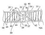
- FIG. 4is a cross sectional view through the connection between two panels of FIG. 1 for the rig mat system.
- FIG. 5is a cross sectional view through one of the panels of FIG. 1 showing an alternative form of the connection.
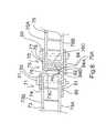
- FIG. 6is a cross sectional view through two of the panels of FIG. 1 showing a further alternative form of the connection.
- the composite panel described in general aboveis shown in FIGS. 1 and 2 and is formed by a honeycomb core panel 10 having a first face 11 and a second opposite face 12 with an array of generally hexagonal tubular cells defined by walls 10 A of the core panel extending between the first and second faces.
- the cellsare formed from strips 15 , 16 arranged side by side of a porous fibrous material which is heat sealed at a sealing line 14 to define the generally hexagonal cells.
- a foam material such as a polyurethane foam 18fills the tubular cells.
- a first fibrous reinforcing cover sheetsuch as a fiberglass mat (or carbon fiber, aramid fiber, Kevlar fiber, polyester fiber, natural fiber—e.g. hemp, flax, straw) 19 extends over the first face 11 of the core panel and a second fibrous reinforcing cover sheet 20 extends over the second face of the core panel.
- a fiberglass mator carbon fiber, aramid fiber, Kevlar fiber, polyester fiber, natural fiber—e.g. hemp, flax, straw
- the first and second cover sheetsare filled with a set resin material 21 which extends from the cover sheets 19 , 20 into the porous fibrous material of the walls 15 , 16 of the core panel so as to form an integral structure of the resin extending between the walls and the sheets.
- the panel described abovecan be formed into a rig mat system which provides a plurality of rectangular panels arranged to be laid side by side and fastened end to end in an array to cover rough ground to form a support surface.
- Each panel 30 , 31have a mounting frame 32 defining two ends 33 , 34 of the panel for connection to a next adjacent panel having a similar frame.
- a first end of the framehas a first connecting member 33 extending along the end which is C-shaped shaped in cross section so as to define a hollow interior 35 with top and bottom horizontal flanges 38 and 39 and a top vertical flange 36 and a bottom vertical flange 37 , the top flange facing downwardly and the bottom flange facing upwardly so as to define an open mouth 40 therebetween.
- the C-shaped memberis preferably rectangular, this is not essential and it may have curved flanges.
- a second end 34 of the framehaving a second connecting member extending along the end which is T-shaped shaped in cross section with a generally upstanding flange 41 connected to the end face of the panel by a connecting bar 42 which is generally at right angles to the upstanding flange 41 and connects to the upstanding flange so as to provide an upwardly extending portion 43 above the bar and a downwardly extending portion 44 below the bar.
- the upstanding flange 41has a height greater than the height of the open mouth 40 and the bar 42 has a length from the upstanding flange to the end face of the panel such that the upstanding flange is inserted through the mouth by tilting the panel and leading the top portion 43 through the open mouth until the flange 41 is wholly within the hollow interior.
- the upstanding flangeis prevented from escaping from the mouth by horizontal movement because the flange 41 is of greater height than the mouth and thus cannot escape.
- the frameincludes two side members 50 and 51 each connected to the first and second connecting members 33 and 34 and each extending along a respective side of the panel.
- the memberscan be formed of metal with the members being connected at the ends by welded butt joints 53 or welded miter joints (not shown).
- Each of the membersincludes a C-shaped channel 48 facing the panel and into which an edge 49 of the panel is inserted.
- the top and bottom surfaces 58 , 59 of the panelare recessed by the thickness of the wall of the C-channel to receive the C-channel to that the top and bottom surfaces of the C-channel are coplanar with the top and bottom surfaces respectively of the panel itself.
- the side and end membersare fastened to the panel and formed integrally with the panel and fastened to the panel by common resin material engaged therein which extends from the top and bottom walls 20 , 21 of the panel through the tube walls 10 A.
- the end walls of the panelare shaped to form the end couplings as previously described which are integral with the panel and formed by the reinforcing sheets at tope and bottom which are brought together and connected byte the injected resin to form the end wall 60 and the T-bar 61 .
- FIG. 6is shown an alternative arrangement for the end couplings 70 and 71 at the ends 49 of the panels.
- the first end coupling 70 of the mounting arrangementhas a first connecting member 77 extending along the first end which is generally L-shaped with a first plate 78 attached to the first surface 76 A of the panel 76 and a first flange 79 substantially at right angles to the first plate 78
- the second end coupling 71 of the mounting arrangementhas a second connecting member 80 extending along the second end which is generally L-shaped with a second plate 81 attached to the second surface 73 A of the panel 73 and a second flange 82 substantially at right angles to the second plate 81 .
- the first and second flanges 79 , 82are arranged in opposed directions so that one can engage over the other to hold the panels against movement horizontally away from one another.
- a third plate 84is attached to the second surface 76 B of the panel 76 at the first end and extends from the second surface 76 B to an end 84 B outwardly beyond a position 84 A beyond the first end 76 C of the first panel 76 and underlying a bottom end 79 A of the first flange 79 to define with the end 79 A of the first flange 79 a slot 85 through which the second flange 82 is inserted.
- the slot 85locates the flange 82 and the plate 81 and prevents downward movement of the plate 81 which sits on the plate 84 .
- the first plate 78 and the third plate 84are fastened together at the end of the first panel by a series of fasteners 90 passing through the first panel 76 adjacent the edge 76 C thus clamping the plates to the edge of the panel.
- the second plateis attached to the end 73 C of the second panel 73 by a fourth plate 92 attached to the first surface 73 B with the second plate and the fourth plate being fastened together at the end of the second panel 73 by a series of fasteners 91 passing through the second panel and clamping the plates to the panel.
Landscapes
- Engineering & Computer Science (AREA)
- Architecture (AREA)
- Civil Engineering (AREA)
- Structural Engineering (AREA)
- Laminated Bodies (AREA)
Abstract
Description
Claims (20)
Priority Applications (2)
| Application Number | Priority Date | Filing Date | Title |
|---|---|---|---|
| US12/480,011US8061929B2 (en) | 2008-06-06 | 2009-06-08 | Rig mat system using panels of composite material |
| US13/301,126US8403593B2 (en) | 2008-06-06 | 2011-11-21 | Rig mat system using panels of composite material |
Applications Claiming Priority (2)
| Application Number | Priority Date | Filing Date | Title |
|---|---|---|---|
| US5944708P | 2008-06-06 | 2008-06-06 | |
| US12/480,011US8061929B2 (en) | 2008-06-06 | 2009-06-08 | Rig mat system using panels of composite material |
Related Child Applications (1)
| Application Number | Title | Priority Date | Filing Date |
|---|---|---|---|
| US13/301,126DivisionUS8403593B2 (en) | 2008-06-06 | 2011-11-21 | Rig mat system using panels of composite material |
Publications (2)
| Publication Number | Publication Date |
|---|---|
| US20090301004A1 US20090301004A1 (en) | 2009-12-10 |
| US8061929B2true US8061929B2 (en) | 2011-11-22 |
Family
ID=41399028
Family Applications (2)
| Application Number | Title | Priority Date | Filing Date |
|---|---|---|---|
| US12/480,011Expired - Fee RelatedUS8061929B2 (en) | 2008-06-06 | 2009-06-08 | Rig mat system using panels of composite material |
| US13/301,126Expired - Fee RelatedUS8403593B2 (en) | 2008-06-06 | 2011-11-21 | Rig mat system using panels of composite material |
Family Applications After (1)
| Application Number | Title | Priority Date | Filing Date |
|---|---|---|---|
| US13/301,126Expired - Fee RelatedUS8403593B2 (en) | 2008-06-06 | 2011-11-21 | Rig mat system using panels of composite material |
Country Status (2)
| Country | Link |
|---|---|
| US (2) | US8061929B2 (en) |
| CA (1) | CA2668999C (en) |
Cited By (39)
| Publication number | Priority date | Publication date | Assignee | Title |
|---|---|---|---|---|
| US20130170907A1 (en)* | 2012-01-02 | 2013-07-04 | Donald O. GUNN | Lightweight support mat for equipment and vehicles |
| US20130309008A1 (en)* | 2012-05-15 | 2013-11-21 | Maxximat Inc. | Ground cover mats with cross beam straps |
| US8616804B2 (en)* | 2010-04-13 | 2013-12-31 | Craig Corser | Modular roadway |
| US20150099377A1 (en)* | 2013-10-09 | 2015-04-09 | Newpark Mats & Integrated Services Llc | Apparatus & Methods for Electrically Grounding a Load-Supporting Surface |
| US9133598B2 (en) | 2013-01-17 | 2015-09-15 | Polymics, Ltd. | Sealed interconnected mat system |
| US9315951B1 (en) | 2014-09-19 | 2016-04-19 | Joe Penland, Jr. | Mat construction having environmentally resistant skin |
| US9315949B1 (en) | 2014-09-23 | 2016-04-19 | Joe Penland, Jr. | Mat construction with environmentally resistant core |
| US9447547B2 (en) | 2014-09-23 | 2016-09-20 | Joe Penland, Jr. | Mat construction with environmentally resistant core |
| US9447548B2 (en) | 2014-09-19 | 2016-09-20 | Joe Penland, Jr. | Industrial mat with molded core and outer abuse surfaces |
| WO2016153734A1 (en) | 2015-03-25 | 2016-09-29 | Penland Jr Joe | Environmentally resistant encapsulated mat construction |
| WO2016153732A1 (en) | 2015-03-25 | 2016-09-29 | Penland Joe Jr | Mat construction with environmentally resistant core |
| US9458578B2 (en) | 2014-11-07 | 2016-10-04 | Erik D. Klein | Timber access mat with grounding |
| US20160301161A1 (en)* | 2013-10-09 | 2016-10-13 | Newpark Mats & Integrated Services Llc | Apparatus and Methods for Electrically Grounding at Least One Mat in a Load-Supporting Surface |
| US9476164B2 (en) | 2014-09-19 | 2016-10-25 | Quality Mat Company | Industrial mat having side bumpers and lifting elements |
| US9486976B1 (en) | 2015-09-15 | 2016-11-08 | Quality Mat Company | Mat construction having environmentally resistant skin |
| US9546455B2 (en)* | 2014-10-23 | 2017-01-17 | Dean Forbes | Rig mat with replaceable deck inserts |
| WO2017040118A1 (en) | 2015-08-28 | 2017-03-09 | Quality Mat Company | Industrial mat with molded core and outer abuse surfaces |
| US9605390B2 (en) | 2014-09-23 | 2017-03-28 | Quality Mat Company | Industrial mats having cost effective core support structures |
| US9617693B1 (en) | 2014-09-23 | 2017-04-11 | Quality Mat Company | Lifting elements for crane mats |
| US9663902B2 (en) | 2014-09-19 | 2017-05-30 | Quality Mat Company | Environmentally resistant encapsulated mat construction |
| US9663903B2 (en) | 2014-09-23 | 2017-05-30 | Quality Mat Company | Industrial mats having plastic or elastomeric side members |
| US9714487B2 (en) | 2014-09-23 | 2017-07-25 | Quality Mat Company | Industrial mats with lifting elements |
| US9822493B2 (en) | 2014-09-19 | 2017-11-21 | Quality Mat Company | Industrial mats having side protection |
| US9845576B2 (en) | 2014-09-23 | 2017-12-19 | Quality Mat Company | Hybrid crane mat utilizing various longitudinal members |
| US9863098B2 (en) | 2014-09-23 | 2018-01-09 | Quality Mat Company | Hybrid crane mat with lifting elements |
| US9915036B2 (en) | 2014-09-23 | 2018-03-13 | Quality Mat Company | Stackable mat construction |
| US9972942B1 (en) | 2013-10-09 | 2018-05-15 | Newpark Mats & Integrated Services Llc | Apparatus and methods for insulating an electrically-groundable support surface |
| US20180209137A1 (en)* | 2017-01-23 | 2018-07-26 | Mitek Holdings, Inc. | Insulated panel assembly |
| US20180274183A1 (en)* | 2017-03-24 | 2018-09-27 | Matrax, Inc. | Industrial support mat interlock device |
| US10113768B2 (en) | 2015-01-23 | 2018-10-30 | Mitek Holdings, Inc. | Insulated panel assembly |
| US10181681B1 (en) | 2017-06-22 | 2019-01-15 | EDK Innovations, LLC | Equipotential grounding grate |
| US10273639B2 (en) | 2014-09-19 | 2019-04-30 | Quality Mat Company | Hybrid industrial mats having side protection |
| US10273638B1 (en) | 2018-03-26 | 2019-04-30 | Quality Mat Company | Laminated mats with closed and strengthened core layer |
| US10287732B1 (en)* | 2018-03-30 | 2019-05-14 | Lawrence Eugene Warford | Temporary walkway |
| WO2020014156A1 (en) | 2018-07-09 | 2020-01-16 | Quality Mat Company | Industrial mats having cost effective core structures |
| US10753050B2 (en) | 2014-09-23 | 2020-08-25 | Quality Mat Company | Industrial mats having cost effective core structures |
| US10774496B2 (en)* | 2017-04-13 | 2020-09-15 | Oxford Plastic Systems Limited | Cover |
| WO2021122197A1 (en) | 2019-12-18 | 2021-06-24 | Low & Bonar B.V. | Material comprising connecting means |
| US11805757B1 (en) | 2019-06-24 | 2023-11-07 | Yak Access LLC | Equipotential security fence and grounding grate |
Families Citing this family (17)
| Publication number | Priority date | Publication date | Assignee | Title |
|---|---|---|---|---|
| US20060096189A1 (en) | 2004-11-09 | 2006-05-11 | Mark Pavlansky | Roof venting system |
| NL2002289C2 (en)* | 2008-12-04 | 2010-06-07 | Gtm Holding B V | Sandwich panel, support member for use in a sandwich panel and aircraft provided with such a sandwich panel. |
| US8545127B2 (en)* | 2010-06-07 | 2013-10-01 | Strad Energy Services Ltd | Rig mat system and method of making the same |
| CN103397768B (en)* | 2013-08-22 | 2015-10-07 | 湖州森宏环保木塑材料有限公司 | Outdoor floor made of wood-plastic composite material |
| CN103821275A (en)* | 2014-02-04 | 2014-05-28 | 王广武 | Externally filled sandwich wall panel and preparation method thereof |
| US10577753B2 (en) | 2015-08-03 | 2020-03-03 | Sterling Site Access Solutions, Llc | Crane mat and method of manufacture |
| CN105133457A (en)* | 2015-08-13 | 2015-12-09 | 湖北华舟重工应急装备股份有限公司 | Hard road surface |
| CN105818454A (en)* | 2016-04-05 | 2016-08-03 | 江苏科悦新材料有限公司 | Automotive composite bottom plate and manufacturing method thereof |
| US10669720B1 (en) | 2017-02-10 | 2020-06-02 | Hibco Plastics, Inc. | Stackable closure strip |
| CN107628190A (en)* | 2017-09-19 | 2018-01-26 | 株洲时代新材料科技股份有限公司 | A kind of lining plate for ship |
| US10458074B1 (en)* | 2018-07-03 | 2019-10-29 | Paul Dagesse | Access mat comprising single unitary pultruded body |
| US11260582B2 (en)* | 2018-10-16 | 2022-03-01 | Divergent Technologies, Inc. | Methods and apparatus for manufacturing optimized panels and other composite structures |
| CN109468905B (en)* | 2018-10-26 | 2020-12-15 | 博兴兴博城建投资集团有限公司 | Temporary paving emergency road based on road construction |
| CN109958253A (en)* | 2019-03-29 | 2019-07-02 | 广东绿屋建筑科技工程有限公司 | A kind of frame structure of integrated wall plate |
| CN112190163A (en)* | 2020-10-30 | 2021-01-08 | 苏州中创铝业有限公司 | Base plate module and base plate structure of bathroom |
| CN113635932B (en)* | 2021-07-08 | 2022-09-30 | 中南大学 | A gradient energy absorption device with embedded tubular honeycomb filled thin-walled structure |
| GB2613769A (en)* | 2021-10-19 | 2023-06-21 | Jonathan Ardern Fergus | A surface panel |
Citations (21)
| Publication number | Priority date | Publication date | Assignee | Title |
|---|---|---|---|---|
| US2430200A (en)* | 1944-11-18 | 1947-11-04 | Nina Mae Wilson | Lock joint |
| US3348459A (en)* | 1967-01-03 | 1967-10-24 | Harvey Aluminum Inc | Interlocking matting and coupling bar therefor |
| US3564801A (en)* | 1968-11-15 | 1971-02-23 | Amado Sanchez Huerta | Joint element for securing partitions or the like |
| US3602110A (en)* | 1968-10-31 | 1971-08-31 | Republic Steel Corp | Lightweight steel land mat |
| US3694983A (en)* | 1970-05-19 | 1972-10-03 | Pierre Jean Couquet | Pile or plastic tiles for flooring and like applications |
| US3859000A (en)* | 1972-03-30 | 1975-01-07 | Reynolds Metals Co | Road construction and panel for making same |
| US4703597A (en)* | 1985-06-28 | 1987-11-03 | Eggemar Bengt V | Arena floor and flooring element |
| US4845907A (en)* | 1987-12-28 | 1989-07-11 | Meek John R | Panel module |
| US5032037A (en)* | 1990-04-12 | 1991-07-16 | Phillips Mark L | Method and apparatus for temporary matting for use at construction sites |
| US5797237A (en)* | 1997-02-28 | 1998-08-25 | Standard Plywoods, Incorporated | Flooring system |
| US5971655A (en)* | 1997-08-19 | 1999-10-26 | Miyagawa Kasei Industry Co., Ltd. | Connection structure of deckings |
| CA2348328A1 (en) | 2001-05-23 | 2002-02-05 | David Stasiewich | Road mats |
| CA2364968A1 (en) | 2001-12-12 | 2003-06-12 | David Stasiewich | Ground cover mat |
| US20030233809A1 (en)* | 2002-04-15 | 2003-12-25 | Darko Pervan | Floorboards for floating floors |
| US6676785B2 (en)* | 2001-04-06 | 2004-01-13 | Ebert Composites Corporation | Method of clinching the top and bottom ends of Z-axis fibers into the respective top and bottom surfaces of a composite laminate |
| US7160055B2 (en) | 2003-01-03 | 2007-01-09 | Shawn Beamish | Road mat |
| US20070250025A1 (en)* | 2006-04-25 | 2007-10-25 | Martin Marietta Materials, Inc. | Composite structural/thermal mat system |
| US7415741B1 (en)* | 2006-01-12 | 2008-08-26 | Imp Inc. | Surgical patient positioner extension unit |
| US20090142542A1 (en)* | 2007-09-27 | 2009-06-04 | Prs Mediterranean Ltd. | Sandwich system |
| US7608313B2 (en)* | 2004-06-04 | 2009-10-27 | Martin Marietta Materials, Inc. | Panel apparatus with supported connection |
| US7641963B2 (en)* | 2002-11-12 | 2010-01-05 | Kronotec Ag | Panel and process for producing a panel |
Family Cites Families (1)
| Publication number | Priority date | Publication date | Assignee | Title |
|---|---|---|---|---|
| JPS54115541A (en)* | 1978-02-28 | 1979-09-08 | Seibu Polymer Kasei Kk | Joint of culvert |
- 2009
- 2009-06-08CACA2668999Apatent/CA2668999C/ennot_activeExpired - Fee Related
- 2009-06-08USUS12/480,011patent/US8061929B2/ennot_activeExpired - Fee Related
- 2011
- 2011-11-21USUS13/301,126patent/US8403593B2/ennot_activeExpired - Fee Related
Patent Citations (22)
| Publication number | Priority date | Publication date | Assignee | Title |
|---|---|---|---|---|
| US2430200A (en)* | 1944-11-18 | 1947-11-04 | Nina Mae Wilson | Lock joint |
| US3348459A (en)* | 1967-01-03 | 1967-10-24 | Harvey Aluminum Inc | Interlocking matting and coupling bar therefor |
| US3602110A (en)* | 1968-10-31 | 1971-08-31 | Republic Steel Corp | Lightweight steel land mat |
| US3564801A (en)* | 1968-11-15 | 1971-02-23 | Amado Sanchez Huerta | Joint element for securing partitions or the like |
| US3694983A (en)* | 1970-05-19 | 1972-10-03 | Pierre Jean Couquet | Pile or plastic tiles for flooring and like applications |
| US3859000A (en)* | 1972-03-30 | 1975-01-07 | Reynolds Metals Co | Road construction and panel for making same |
| US4703597A (en)* | 1985-06-28 | 1987-11-03 | Eggemar Bengt V | Arena floor and flooring element |
| US4845907A (en)* | 1987-12-28 | 1989-07-11 | Meek John R | Panel module |
| US5032037A (en)* | 1990-04-12 | 1991-07-16 | Phillips Mark L | Method and apparatus for temporary matting for use at construction sites |
| US5797237A (en)* | 1997-02-28 | 1998-08-25 | Standard Plywoods, Incorporated | Flooring system |
| US5971655A (en)* | 1997-08-19 | 1999-10-26 | Miyagawa Kasei Industry Co., Ltd. | Connection structure of deckings |
| US6676785B2 (en)* | 2001-04-06 | 2004-01-13 | Ebert Composites Corporation | Method of clinching the top and bottom ends of Z-axis fibers into the respective top and bottom surfaces of a composite laminate |
| CA2348328A1 (en) | 2001-05-23 | 2002-02-05 | David Stasiewich | Road mats |
| US6652183B2 (en)* | 2001-05-23 | 2003-11-25 | David Stasiewich | Road mats |
| CA2364968A1 (en) | 2001-12-12 | 2003-06-12 | David Stasiewich | Ground cover mat |
| US20030233809A1 (en)* | 2002-04-15 | 2003-12-25 | Darko Pervan | Floorboards for floating floors |
| US7641963B2 (en)* | 2002-11-12 | 2010-01-05 | Kronotec Ag | Panel and process for producing a panel |
| US7160055B2 (en) | 2003-01-03 | 2007-01-09 | Shawn Beamish | Road mat |
| US7608313B2 (en)* | 2004-06-04 | 2009-10-27 | Martin Marietta Materials, Inc. | Panel apparatus with supported connection |
| US7415741B1 (en)* | 2006-01-12 | 2008-08-26 | Imp Inc. | Surgical patient positioner extension unit |
| US20070250025A1 (en)* | 2006-04-25 | 2007-10-25 | Martin Marietta Materials, Inc. | Composite structural/thermal mat system |
| US20090142542A1 (en)* | 2007-09-27 | 2009-06-04 | Prs Mediterranean Ltd. | Sandwich system |
Cited By (53)
| Publication number | Priority date | Publication date | Assignee | Title |
|---|---|---|---|---|
| US8616804B2 (en)* | 2010-04-13 | 2013-12-31 | Craig Corser | Modular roadway |
| US20130170907A1 (en)* | 2012-01-02 | 2013-07-04 | Donald O. GUNN | Lightweight support mat for equipment and vehicles |
| US20130309008A1 (en)* | 2012-05-15 | 2013-11-21 | Maxximat Inc. | Ground cover mats with cross beam straps |
| US9366001B2 (en) | 2013-01-17 | 2016-06-14 | Polymics, Ltd. | Sealed interconnected mat system |
| US9133598B2 (en) | 2013-01-17 | 2015-09-15 | Polymics, Ltd. | Sealed interconnected mat system |
| US20170338596A1 (en)* | 2013-10-09 | 2017-11-23 | Newpark Mats & Integrated Services Llc | Apparatus for electrically grounding at least one mat |
| US9985390B2 (en)* | 2013-10-09 | 2018-05-29 | Newpark Mats & Integrated Services Llc | Electrically groundable support surface and related methods |
| US9337586B2 (en)* | 2013-10-09 | 2016-05-10 | Newpark Mats & Integrated Sevices, LLC | Apparatus and methods for electrically grounding a load-supporting surface |
| US9368918B2 (en)* | 2013-10-09 | 2016-06-14 | Newpark Mats & Integrated Services Llc | Apparatus and methods for electrically grounding a load-supporting surface |
| US9735510B2 (en)* | 2013-10-09 | 2017-08-15 | Newpark Mats & Integrated Services Llc | Apparatus and methods for electrically grounding at least one mat in a load-supporting surface |
| US20150099377A1 (en)* | 2013-10-09 | 2015-04-09 | Newpark Mats & Integrated Services Llc | Apparatus & Methods for Electrically Grounding a Load-Supporting Surface |
| US10340637B1 (en) | 2013-10-09 | 2019-07-02 | Newpark Mats & Integrated Services Llc | Electrically conductive support surface and related methods |
| US9972942B1 (en) | 2013-10-09 | 2018-05-15 | Newpark Mats & Integrated Services Llc | Apparatus and methods for insulating an electrically-groundable support surface |
| US10355417B1 (en) | 2013-10-09 | 2019-07-16 | Newpark Mats & Integrated Services Llc | Apparatus and methods for electrically coupling multiple electrically-conductive ground covers |
| US20160301161A1 (en)* | 2013-10-09 | 2016-10-13 | Newpark Mats & Integrated Services Llc | Apparatus and Methods for Electrically Grounding at Least One Mat in a Load-Supporting Surface |
| US9663902B2 (en) | 2014-09-19 | 2017-05-30 | Quality Mat Company | Environmentally resistant encapsulated mat construction |
| US9476164B2 (en) | 2014-09-19 | 2016-10-25 | Quality Mat Company | Industrial mat having side bumpers and lifting elements |
| US10017903B2 (en) | 2014-09-19 | 2018-07-10 | Quality Mat Company | Industrial mats having side protection |
| US10273639B2 (en) | 2014-09-19 | 2019-04-30 | Quality Mat Company | Hybrid industrial mats having side protection |
| US9447548B2 (en) | 2014-09-19 | 2016-09-20 | Joe Penland, Jr. | Industrial mat with molded core and outer abuse surfaces |
| US9822493B2 (en) | 2014-09-19 | 2017-11-21 | Quality Mat Company | Industrial mats having side protection |
| US9315951B1 (en) | 2014-09-19 | 2016-04-19 | Joe Penland, Jr. | Mat construction having environmentally resistant skin |
| US9605390B2 (en) | 2014-09-23 | 2017-03-28 | Quality Mat Company | Industrial mats having cost effective core support structures |
| US9863098B2 (en) | 2014-09-23 | 2018-01-09 | Quality Mat Company | Hybrid crane mat with lifting elements |
| US9714487B2 (en) | 2014-09-23 | 2017-07-25 | Quality Mat Company | Industrial mats with lifting elements |
| US9617693B1 (en) | 2014-09-23 | 2017-04-11 | Quality Mat Company | Lifting elements for crane mats |
| US9315949B1 (en) | 2014-09-23 | 2016-04-19 | Joe Penland, Jr. | Mat construction with environmentally resistant core |
| US9447547B2 (en) | 2014-09-23 | 2016-09-20 | Joe Penland, Jr. | Mat construction with environmentally resistant core |
| US9845576B2 (en) | 2014-09-23 | 2017-12-19 | Quality Mat Company | Hybrid crane mat utilizing various longitudinal members |
| US9663903B2 (en) | 2014-09-23 | 2017-05-30 | Quality Mat Company | Industrial mats having plastic or elastomeric side members |
| US9915036B2 (en) | 2014-09-23 | 2018-03-13 | Quality Mat Company | Stackable mat construction |
| US11066788B2 (en) | 2014-09-23 | 2021-07-20 | Quality Mat Company | Industrial mats having cost effective core structures |
| US10753050B2 (en) | 2014-09-23 | 2020-08-25 | Quality Mat Company | Industrial mats having cost effective core structures |
| US9546455B2 (en)* | 2014-10-23 | 2017-01-17 | Dean Forbes | Rig mat with replaceable deck inserts |
| US10011959B2 (en) | 2014-11-07 | 2018-07-03 | EDK Innovations, LLC | Timber access mat with grounding |
| US9458578B2 (en) | 2014-11-07 | 2016-10-04 | Erik D. Klein | Timber access mat with grounding |
| US10106935B1 (en) | 2014-11-07 | 2018-10-23 | EDK Innovations, LLC | Electrically-grounded work platform |
| US10113768B2 (en) | 2015-01-23 | 2018-10-30 | Mitek Holdings, Inc. | Insulated panel assembly |
| WO2016153734A1 (en) | 2015-03-25 | 2016-09-29 | Penland Jr Joe | Environmentally resistant encapsulated mat construction |
| WO2016153732A1 (en) | 2015-03-25 | 2016-09-29 | Penland Joe Jr | Mat construction with environmentally resistant core |
| WO2017040118A1 (en) | 2015-08-28 | 2017-03-09 | Quality Mat Company | Industrial mat with molded core and outer abuse surfaces |
| US9486976B1 (en) | 2015-09-15 | 2016-11-08 | Quality Mat Company | Mat construction having environmentally resistant skin |
| US20180209137A1 (en)* | 2017-01-23 | 2018-07-26 | Mitek Holdings, Inc. | Insulated panel assembly |
| US10316516B2 (en)* | 2017-01-23 | 2019-06-11 | Mitek Holdings, Inc. | Insulated panel assembly |
| US10662589B2 (en)* | 2017-03-24 | 2020-05-26 | Matrax, Inc. | Industrial support mat interlock device |
| US20180274183A1 (en)* | 2017-03-24 | 2018-09-27 | Matrax, Inc. | Industrial support mat interlock device |
| US10774496B2 (en)* | 2017-04-13 | 2020-09-15 | Oxford Plastic Systems Limited | Cover |
| US10181681B1 (en) | 2017-06-22 | 2019-01-15 | EDK Innovations, LLC | Equipotential grounding grate |
| US10273638B1 (en) | 2018-03-26 | 2019-04-30 | Quality Mat Company | Laminated mats with closed and strengthened core layer |
| US10287732B1 (en)* | 2018-03-30 | 2019-05-14 | Lawrence Eugene Warford | Temporary walkway |
| WO2020014156A1 (en) | 2018-07-09 | 2020-01-16 | Quality Mat Company | Industrial mats having cost effective core structures |
| US11805757B1 (en) | 2019-06-24 | 2023-11-07 | Yak Access LLC | Equipotential security fence and grounding grate |
| WO2021122197A1 (en) | 2019-12-18 | 2021-06-24 | Low & Bonar B.V. | Material comprising connecting means |
Also Published As
| Publication number | Publication date |
|---|---|
| CA2668999A1 (en) | 2009-12-06 |
| CA2668999C (en) | 2012-11-20 |
| US8403593B2 (en) | 2013-03-26 |
| US20090301004A1 (en) | 2009-12-10 |
| US20120163910A1 (en) | 2012-06-28 |
Similar Documents
| Publication | Publication Date | Title |
|---|---|---|
| US8061929B2 (en) | Rig mat system using panels of composite material | |
| US8062728B2 (en) | Composite material formed from foam filled honeycomb panel with top and bottom resin filled sheets | |
| US10550569B2 (en) | Composite floor structure and method of making the same | |
| US8342598B2 (en) | Structure including a composite panel joint | |
| CA2807710C (en) | Composite panel and joint construction | |
| US7575264B1 (en) | Cargo bed structure comprising fiber reinforced polymer components | |
| US10829163B2 (en) | Transverse beam for composite floor structure and method of making the same | |
| US8186747B2 (en) | Modular composite structural component and structures formed therewith | |
| US6523324B1 (en) | Building panels with plastic impregnated paper | |
| US20100005732A1 (en) | Building roof structure having a round corner | |
| CA2365143A1 (en) | Lightweight fiber reinforced polymer composite modular panel | |
| JP4596920B2 (en) | Large composite structure and method for producing large composite structure | |
| US20100050549A1 (en) | Joint of parallel sandwich panels | |
| US20160304131A1 (en) | Floor Construction for a Vehicle | |
| WO2000017036A1 (en) | Floor panel for a vehicle floor | |
| US20100320201A1 (en) | Tank formed from panels of composite material | |
| US8746477B2 (en) | Tank formed from panels of composite material | |
| US8375656B2 (en) | Insulating sheet and refrigerated trailer components formed from same | |
| CA2611344C (en) | Insulating sheet and refrigerated trailer components formed from same | |
| CA2750915A1 (en) | Tank formed from panels of composite material |
Legal Events
| Date | Code | Title | Description |
|---|---|---|---|
| STCF | Information on status: patent grant | Free format text:PATENTED CASE | |
| AS | Assignment | Owner name:RHINOKORE COMPOSITES MANUFACTURING PARTNERSHIP, CA Free format text:ASSIGNMENT OF ASSIGNORS INTEREST;ASSIGNOR:DAGESSE, PAUL;REEL/FRAME:027249/0786 Effective date:20111028 | |
| FEPP | Fee payment procedure | Free format text:PAYOR NUMBER ASSIGNED (ORIGINAL EVENT CODE: ASPN); ENTITY STATUS OF PATENT OWNER: SMALL ENTITY | |
| FPAY | Fee payment | Year of fee payment:4 | |
| AS | Assignment | Owner name:RHINOKORE COMPOSITES SOLUTIONS LP, CANADA Free format text:ASSIGNMENT OF ASSIGNORS INTEREST;ASSIGNOR:RHINOKORE COMPOSITES MANUFACTURING PARTNERSHIP;REEL/FRAME:038639/0579 Effective date:20160304 | |
| AS | Assignment | Owner name:RHINOKORE COMPOSITES SOLUTIONS LP, CANADA Free format text:ASSIGNMENT OF ASSIGNORS INTEREST;ASSIGNOR:RHINOKORE COMPOSITES MANUFACTURING PARTNERSHIP;REEL/FRAME:040113/0993 Effective date:20160304 | |
| MAFP | Maintenance fee payment | Free format text:PAYMENT OF MAINTENANCE FEE, 8TH YR, SMALL ENTITY (ORIGINAL EVENT CODE: M2552); ENTITY STATUS OF PATENT OWNER: SMALL ENTITY Year of fee payment:8 | |
| FEPP | Fee payment procedure | Free format text:MAINTENANCE FEE REMINDER MAILED (ORIGINAL EVENT CODE: REM.); ENTITY STATUS OF PATENT OWNER: SMALL ENTITY | |
| LAPS | Lapse for failure to pay maintenance fees | Free format text:PATENT EXPIRED FOR FAILURE TO PAY MAINTENANCE FEES (ORIGINAL EVENT CODE: EXP.); ENTITY STATUS OF PATENT OWNER: SMALL ENTITY | |
| STCH | Information on status: patent discontinuation | Free format text:PATENT EXPIRED DUE TO NONPAYMENT OF MAINTENANCE FEES UNDER 37 CFR 1.362 | |
| FP | Lapsed due to failure to pay maintenance fee | Effective date:20231122 |