US8061411B2 - Heat dissipation device - Google Patents
Heat dissipation deviceDownload PDFInfo
- Publication number
- US8061411B2 US8061411B2US12/396,484US39648409AUS8061411B2US 8061411 B2US8061411 B2US 8061411B2US 39648409 AUS39648409 AUS 39648409AUS 8061411 B2US8061411 B2US 8061411B2
- Authority
- US
- United States
- Prior art keywords
- fin set
- heat dissipation
- dissipation device
- fans
- driving part
- Prior art date
- Legal status (The legal status is an assumption and is not a legal conclusion. Google has not performed a legal analysis and makes no representation as to the accuracy of the status listed.)
- Expired - Fee Related, expires
Links
- 230000017525heat dissipationEffects0.000titleclaimsabstractdescription33
- 238000001704evaporationMethods0.000claimsdescription5
- 230000000284resting effectEffects0.000claims1
- 239000003570airSubstances0.000description1
- 239000012080ambient airSubstances0.000description1
- 239000000463materialSubstances0.000description1
Images


Classifications
- H—ELECTRICITY
- H01—ELECTRIC ELEMENTS
- H01L—SEMICONDUCTOR DEVICES NOT COVERED BY CLASS H10
- H01L23/00—Details of semiconductor or other solid state devices
- H01L23/34—Arrangements for cooling, heating, ventilating or temperature compensation ; Temperature sensing arrangements
- H01L23/36—Selection of materials, or shaping, to facilitate cooling or heating, e.g. heatsinks
- H01L23/367—Cooling facilitated by shape of device
- H01L23/3672—Foil-like cooling fins or heat sinks
- H—ELECTRICITY
- H01—ELECTRIC ELEMENTS
- H01L—SEMICONDUCTOR DEVICES NOT COVERED BY CLASS H10
- H01L23/00—Details of semiconductor or other solid state devices
- H01L23/34—Arrangements for cooling, heating, ventilating or temperature compensation ; Temperature sensing arrangements
- H01L23/42—Fillings or auxiliary members in containers or encapsulations selected or arranged to facilitate heating or cooling
- H01L23/427—Cooling by change of state, e.g. use of heat pipes
- H—ELECTRICITY
- H01—ELECTRIC ELEMENTS
- H01L—SEMICONDUCTOR DEVICES NOT COVERED BY CLASS H10
- H01L23/00—Details of semiconductor or other solid state devices
- H01L23/34—Arrangements for cooling, heating, ventilating or temperature compensation ; Temperature sensing arrangements
- H01L23/46—Arrangements for cooling, heating, ventilating or temperature compensation ; Temperature sensing arrangements involving the transfer of heat by flowing fluids
- H01L23/467—Arrangements for cooling, heating, ventilating or temperature compensation ; Temperature sensing arrangements involving the transfer of heat by flowing fluids by flowing gases, e.g. air
- H—ELECTRICITY
- H01—ELECTRIC ELEMENTS
- H01L—SEMICONDUCTOR DEVICES NOT COVERED BY CLASS H10
- H01L2924/00—Indexing scheme for arrangements or methods for connecting or disconnecting semiconductor or solid-state bodies as covered by H01L24/00
- H01L2924/0001—Technical content checked by a classifier
- H01L2924/0002—Not covered by any one of groups H01L24/00, H01L24/00 and H01L2224/00
Definitions
- the disclosurerelates generally to heat dissipation, and more particularly, to a heat dissipation device incorporating fans to produce airflow in different directions.
- a heat sinkis attached to an outer surface of the electronic device to absorb heat from the electronic device, and the heat absorbed by the heat sink is dissipated to ambient air.
- a fan and heat pipesare applied to the heat sink.
- the fanis fixed in a determined position of a top or a lateral side of the heat sink by a fan holder and cannot be redirected.
- the fan of the heat dissipation devicecan only produce airflow in a single direction in the heat sink. Therefore, when the heat sink has a large dimension, the airflow generated by the fan cannot reach every part of the heat sink, and some parts of the heat sink deprived of the airflow accumulate more heat therein, lowering heat dissipation efficiency of the heat dissipation device for the electronic device.
- FIG. 1is an assembled view of a heat dissipation device in accordance with an embodiment of the present disclosure.
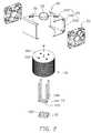
- FIG. 2is an exploded view of the heat dissipation device of FIG. 1 .
- FIG. 3is an inverted view of the heat dissipation device of FIG. 2 .
- FIG. 4is an assembled view of the heat dissipation device of FIG. 3 .
- FIGS. 1 to 4illustrate a heat dissipation device in accordance with an embodiment of the present disclosure.
- the heat dissipation deviceremoves heat from an electronic device (not shown) and other electronic components (not shown) in the vicinity of the electronic device.
- the heat dissipation devicecomprises a heat sink 10 , two fans 30 and a fixing member 20 pivotally connected to a top of the heat sink 10 to rotatably mount the fans 20 at a circumference of the heat sink 10 .
- the heat sink 10comprises a base plate 12 in contact with the electronic device, a fin set 16 , two heat pipes 14 thermally connecting the base plate 12 and the fin set 16 and a vertical retaining pole 18 extending through a centre of the fin set 16 .
- the base plate 12is rectangular and defines two elongated receiving grooves 120 therein. The two receiving grooves 120 are separated and perpendicular to two opposite lateral sides thereof.
- the fin set 16is columnar and comprises a plurality of circular-sheet fins 160 separated and parallel to the base plate 12 .
- the fin set 16defines a vertical engaging hole (not labeled) in the centre thereof engagingly receiving the retaining pole 18 .
- the fin set 16defines a plurality of air passages between the fins 160 for airflow generated by the fans 30 .
- the retaining pole 18 received in the engaging hole of the fin set 16is perpendicular to the fins 160 and has a lower end extending downwardly from a bottom of the fin set 16 and an upper end projecting upwardly from a top of the fin set 16 .
- the lower end of the retaining pole 18contacts the top surface of the base plate 12 and is located between the two receiving grooves 120 of the base plate 12 .
- Each heat pipe 14comprises an evaporating section 142 received in the corresponding receiving groove 120 of the base plate 12 and two condensing sections 146 extending upwardly and perpendicularly from two opposite ends of the evaporating section 142 .
- the two condensing sections 146are received in two neighboring receiving holes 162 of the fin set 16 and parallel to the retaining pole 18 .
- Each heat pipe 14further has an adiabatic section 144 interconnecting the evaporating section 142 and a corresponding one of the condensing sections 146 .
- the fixing member 20comprises a driving part 22 mounted on the top of the fin set 16 , two fixing parts 24 at two opposite sides of the circumference of the fin set 16 and two connecting arms 26 extending outwardly from two opposite sides of the driving part 22 and connecting the driving part 22 and the two fixing parts 24 .
- the driving part 22located at a centre of the top of the fin set 16 , is connected to the upper end of the retaining pole 18 and has a motor (not shown) incorporated therein to rotate the connecting arms 26 and the mounting parts 24 around the fin set 16 relative to the retaining pole 18 .
- Each mounting part 24comprises a top panel 244 connected to a corresponding connecting arm 26 , a bottom panel 246 parallel to the top panel 244 and a side panel 242 connected to outer side edges of the top of bottom panels 244 , 246 together.
- the top panel 244 and the bottom panel 246are two equal three-sided polygons, each having a curved inner side curving inwardly to snugly surround the circumference of the fin set 16 , whereby the inner edges of the top and bottom panels 244 , 246 embrace the fin set 16 in “( )”-fashion.
- Outer side edges of the top and bottom panels 244 , 246cooperate with two vertical outer side edges of the two side panels 242 to define two fixing faces on which the two fans 30 are mounted.
- the two conducting arms 26are collinear.
- the two side panels 242 of the mounting parts 24directly face each other, and are parallel to each other.
- the two mounting parts 24are symmetrical relative to the retaining pole 18 received in the centre of the fin set 16 .
- the two fans 30are mounted on the two fixing faces of the mounting parts 24 and face different parts of the fin set 16 .
- the fans 30are parallel to each other and respectively produce two airflows through the fin set 16 in two parallel, opposite directions.
- heat generated by the electronic deviceis absorbed by the base plate 12 of the heat sink 10 , transferred from the base plate 12 to the fin set 16 via the heat pipes 14 and conducted to the ambient by the airflow produced by the fans 30 , whereby the electronic device is cooled efficiently. Furthermore, rotating of the fixing member 20 combined with the fans 30 driven by the driving part 22 of the fixing member 20 can accelerate airflow speeds generated by the fans 30 and distribute the airflow evenly over the fin set 16 to thereby enhance heat dissipating ability of the heat dissipation device.
Landscapes
- Engineering & Computer Science (AREA)
- Physics & Mathematics (AREA)
- Condensed Matter Physics & Semiconductors (AREA)
- General Physics & Mathematics (AREA)
- Computer Hardware Design (AREA)
- Microelectronics & Electronic Packaging (AREA)
- Power Engineering (AREA)
- Chemical & Material Sciences (AREA)
- Materials Engineering (AREA)
- Cooling Or The Like Of Electrical Apparatus (AREA)
Abstract
Description
Claims (16)
Applications Claiming Priority (3)
| Application Number | Priority Date | Filing Date | Title |
|---|---|---|---|
| CN200810305182.8 | 2008-10-24 | ||
| CN200810305182 | 2008-10-24 | ||
| CN2008103051828ACN101730451B (en) | 2008-10-24 | 2008-10-24 | Heat radiation device |
Publications (2)
| Publication Number | Publication Date |
|---|---|
| US20100101757A1 US20100101757A1 (en) | 2010-04-29 |
| US8061411B2true US8061411B2 (en) | 2011-11-22 |
Family
ID=42116356
Family Applications (1)
| Application Number | Title | Priority Date | Filing Date |
|---|---|---|---|
| US12/396,484Expired - Fee RelatedUS8061411B2 (en) | 2008-10-24 | 2009-03-03 | Heat dissipation device |
Country Status (2)
| Country | Link |
|---|---|
| US (1) | US8061411B2 (en) |
| CN (1) | CN101730451B (en) |
Cited By (32)
| Publication number | Priority date | Publication date | Assignee | Title |
|---|---|---|---|---|
| US8934235B2 (en) | 2012-01-23 | 2015-01-13 | Microsoft Corporation | Heat transfer device with phase change material |
| US9223138B2 (en) | 2011-12-23 | 2015-12-29 | Microsoft Technology Licensing, Llc | Pixel opacity for augmented reality |
| US9297996B2 (en) | 2012-02-15 | 2016-03-29 | Microsoft Technology Licensing, Llc | Laser illumination scanning |
| US9304235B2 (en) | 2014-07-30 | 2016-04-05 | Microsoft Technology Licensing, Llc | Microfabrication |
| US9311909B2 (en) | 2012-09-28 | 2016-04-12 | Microsoft Technology Licensing, Llc | Sensed sound level based fan speed adjustment |
| US9372347B1 (en) | 2015-02-09 | 2016-06-21 | Microsoft Technology Licensing, Llc | Display system |
| US9423360B1 (en) | 2015-02-09 | 2016-08-23 | Microsoft Technology Licensing, Llc | Optical components |
| US9429692B1 (en) | 2015-02-09 | 2016-08-30 | Microsoft Technology Licensing, Llc | Optical components |
| US20160341498A1 (en)* | 2015-05-20 | 2016-11-24 | Other Lab, Llc | Membrane heat exchanger system and method |
| US9513480B2 (en) | 2015-02-09 | 2016-12-06 | Microsoft Technology Licensing, Llc | Waveguide |
| US9535253B2 (en) | 2015-02-09 | 2017-01-03 | Microsoft Technology Licensing, Llc | Display system |
| US9578318B2 (en) | 2012-03-14 | 2017-02-21 | Microsoft Technology Licensing, Llc | Imaging structure emitter calibration |
| US9581820B2 (en) | 2012-06-04 | 2017-02-28 | Microsoft Technology Licensing, Llc | Multiple waveguide imaging structure |
| US9606586B2 (en) | 2012-01-23 | 2017-03-28 | Microsoft Technology Licensing, Llc | Heat transfer device |
| US9717981B2 (en) | 2012-04-05 | 2017-08-01 | Microsoft Technology Licensing, Llc | Augmented reality and physical games |
| US9726887B2 (en) | 2012-02-15 | 2017-08-08 | Microsoft Technology Licensing, Llc | Imaging structure color conversion |
| US9779643B2 (en) | 2012-02-15 | 2017-10-03 | Microsoft Technology Licensing, Llc | Imaging structure emitter configurations |
| US9827209B2 (en) | 2015-02-09 | 2017-11-28 | Microsoft Technology Licensing, Llc | Display system |
| US20180023579A1 (en)* | 2016-07-20 | 2018-01-25 | Lg Electronics Inc. | Blower |
| US10018844B2 (en) | 2015-02-09 | 2018-07-10 | Microsoft Technology Licensing, Llc | Wearable image display system |
| US10191515B2 (en) | 2012-03-28 | 2019-01-29 | Microsoft Technology Licensing, Llc | Mobile device light guide display |
| US10192358B2 (en) | 2012-12-20 | 2019-01-29 | Microsoft Technology Licensing, Llc | Auto-stereoscopic augmented reality display |
| US10254942B2 (en) | 2014-07-31 | 2019-04-09 | Microsoft Technology Licensing, Llc | Adaptive sizing and positioning of application windows |
| US10317677B2 (en) | 2015-02-09 | 2019-06-11 | Microsoft Technology Licensing, Llc | Display system |
| US10388073B2 (en) | 2012-03-28 | 2019-08-20 | Microsoft Technology Licensing, Llc | Augmented reality light guide display |
| US10502876B2 (en) | 2012-05-22 | 2019-12-10 | Microsoft Technology Licensing, Llc | Waveguide optics focus elements |
| US10592080B2 (en) | 2014-07-31 | 2020-03-17 | Microsoft Technology Licensing, Llc | Assisted presentation of application windows |
| US10678412B2 (en) | 2014-07-31 | 2020-06-09 | Microsoft Technology Licensing, Llc | Dynamic joint dividers for application windows |
| US10845133B2 (en) | 2017-10-10 | 2020-11-24 | Other Lab, Llc | Conformable heat exchanger system and method |
| US11068049B2 (en) | 2012-03-23 | 2021-07-20 | Microsoft Technology Licensing, Llc | Light guide display and field of view |
| US11086216B2 (en) | 2015-02-09 | 2021-08-10 | Microsoft Technology Licensing, Llc | Generating electronic components |
| US11173575B2 (en) | 2019-01-29 | 2021-11-16 | Treau, Inc. | Film heat exchanger coupling system and method |
Families Citing this family (12)
| Publication number | Priority date | Publication date | Assignee | Title |
|---|---|---|---|---|
| CN102056461A (en)* | 2009-11-05 | 2011-05-11 | 鸿富锦精密工业(深圳)有限公司 | Heat dissipating device |
| CN102425736A (en)* | 2011-12-14 | 2012-04-25 | 中山伟强科技有限公司 | High-power LED lamp |
| US20130284408A1 (en)* | 2012-04-30 | 2013-10-31 | Spx Corporation | Reservoir Cooling Apparaturs and Method |
| US9532485B2 (en)* | 2014-02-21 | 2016-12-27 | Lenovo (Beijing) Co., Ltd. | Heat dissipating device and electronic apparatus |
| US10855725B2 (en)* | 2016-06-02 | 2020-12-01 | Microsoft Technology Licensing, Llc | Hardware-based virtualized security isolation |
| CN106558562A (en)* | 2016-11-21 | 2017-04-05 | 武汉精立电子技术有限公司 | A kind of high power load metal-oxide-semiconductor heat abstractor |
| TWI735686B (en)* | 2017-10-20 | 2021-08-11 | 鴻騰精密科技股份有限公司 | Electrical connector assembly |
| CN109768400A (en)* | 2017-11-09 | 2019-05-17 | 富士康(昆山)电脑接插件有限公司 | Electric coupler component |
| CN109407806B (en)* | 2018-12-06 | 2024-03-29 | 深圳市超频三科技股份有限公司 | Radiator |
| CN109967887A (en)* | 2019-04-09 | 2019-07-05 | 深圳市安思科电子科技有限公司 | A kind of heavy duty detergent laser marking device of good heat dissipation effect |
| CN117432642A (en)* | 2022-07-29 | 2024-01-23 | 中兴智能科技南京有限公司 | Fan unit, heat abstractor and electronic equipment |
| US20250107047A1 (en)* | 2023-09-25 | 2025-03-27 | Google Llc | Methods Of Cooling A Vertical Line Card |
Citations (13)
| Publication number | Priority date | Publication date | Assignee | Title |
|---|---|---|---|---|
| US4273075A (en)* | 1979-09-07 | 1981-06-16 | Freihage Dean A | Heat generating device |
| US20020167798A1 (en)* | 2001-05-14 | 2002-11-14 | Delta Electronics, Inc. | Heat-dissipating assembly having heat sink and dual hot-swapped fans |
| US20040042177A1 (en)* | 2002-08-30 | 2004-03-04 | Ehood Geva | Heat sink for automatic assembling |
| US20040256085A1 (en)* | 2003-06-20 | 2004-12-23 | Barsun Stephan Karl | Finned device for removing heat from an electronic component |
| US20050087329A1 (en)* | 2003-10-03 | 2005-04-28 | Jie Zhang | Heat dissipation module with a pair of fans |
| US20060109628A1 (en)* | 2004-11-19 | 2006-05-25 | Searby Tom J | Cooling apparatus for electronic devices |
| US20070256813A1 (en)* | 2006-04-19 | 2007-11-08 | Ama Precision Inc. | Direction-adjustable diffusive device |
| US20080041561A1 (en)* | 2006-08-18 | 2008-02-21 | Foxconn Technology Co., Ltd. | Heat dissipation device |
| US20080314555A1 (en)* | 2007-06-22 | 2008-12-25 | Foxconn Technology Co., Ltd. | Heat dissipation device |
| US7495913B1 (en)* | 2007-08-09 | 2009-02-24 | Fu Zhun Precision Industry (Shen Zhen) Co., Ltd. | Heat dissipating assembly having a fan duct |
| US20090317240A1 (en)* | 2008-06-23 | 2009-12-24 | Wei Shao-Tsung | Adjustable multi-outlet verticle tower fan |
| US7701718B2 (en)* | 2008-09-23 | 2010-04-20 | Fu Zhun Precision Industry (Shen Zhen) Co., Ltd. | Heat sink assembly |
| US20100314080A1 (en)* | 2009-06-15 | 2010-12-16 | Fu Zhun Precision Industry (Shen Zhen) Co., Ltd. | Heat dissipation device |
Family Cites Families (4)
| Publication number | Priority date | Publication date | Assignee | Title |
|---|---|---|---|---|
| US20020036586A1 (en)* | 2000-09-22 | 2002-03-28 | Tantivy Communications, Inc. | Adaptive antenna for use in wireless communication systems |
| US6593891B2 (en)* | 2001-10-19 | 2003-07-15 | Hitachi Cable, Ltd. | Antenna apparatus having cross-shaped slot |
| CN2807325Y (en)* | 2005-05-24 | 2006-08-16 | 幸孺企业有限公司 | Cooling device that can adjust the position of the fan in multiple directions |
| CN100584172C (en)* | 2006-07-21 | 2010-01-20 | 富准精密工业(深圳)有限公司 | Heat radiating device |
- 2008
- 2008-10-24CNCN2008103051828Apatent/CN101730451B/ennot_activeExpired - Fee Related
- 2009
- 2009-03-03USUS12/396,484patent/US8061411B2/ennot_activeExpired - Fee Related
Patent Citations (13)
| Publication number | Priority date | Publication date | Assignee | Title |
|---|---|---|---|---|
| US4273075A (en)* | 1979-09-07 | 1981-06-16 | Freihage Dean A | Heat generating device |
| US20020167798A1 (en)* | 2001-05-14 | 2002-11-14 | Delta Electronics, Inc. | Heat-dissipating assembly having heat sink and dual hot-swapped fans |
| US20040042177A1 (en)* | 2002-08-30 | 2004-03-04 | Ehood Geva | Heat sink for automatic assembling |
| US20040256085A1 (en)* | 2003-06-20 | 2004-12-23 | Barsun Stephan Karl | Finned device for removing heat from an electronic component |
| US20050087329A1 (en)* | 2003-10-03 | 2005-04-28 | Jie Zhang | Heat dissipation module with a pair of fans |
| US20060109628A1 (en)* | 2004-11-19 | 2006-05-25 | Searby Tom J | Cooling apparatus for electronic devices |
| US20070256813A1 (en)* | 2006-04-19 | 2007-11-08 | Ama Precision Inc. | Direction-adjustable diffusive device |
| US20080041561A1 (en)* | 2006-08-18 | 2008-02-21 | Foxconn Technology Co., Ltd. | Heat dissipation device |
| US20080314555A1 (en)* | 2007-06-22 | 2008-12-25 | Foxconn Technology Co., Ltd. | Heat dissipation device |
| US7495913B1 (en)* | 2007-08-09 | 2009-02-24 | Fu Zhun Precision Industry (Shen Zhen) Co., Ltd. | Heat dissipating assembly having a fan duct |
| US20090317240A1 (en)* | 2008-06-23 | 2009-12-24 | Wei Shao-Tsung | Adjustable multi-outlet verticle tower fan |
| US7701718B2 (en)* | 2008-09-23 | 2010-04-20 | Fu Zhun Precision Industry (Shen Zhen) Co., Ltd. | Heat sink assembly |
| US20100314080A1 (en)* | 2009-06-15 | 2010-12-16 | Fu Zhun Precision Industry (Shen Zhen) Co., Ltd. | Heat dissipation device |
Cited By (41)
| Publication number | Priority date | Publication date | Assignee | Title |
|---|---|---|---|---|
| US9223138B2 (en) | 2011-12-23 | 2015-12-29 | Microsoft Technology Licensing, Llc | Pixel opacity for augmented reality |
| US8934235B2 (en) | 2012-01-23 | 2015-01-13 | Microsoft Corporation | Heat transfer device with phase change material |
| US9606586B2 (en) | 2012-01-23 | 2017-03-28 | Microsoft Technology Licensing, Llc | Heat transfer device |
| US9726887B2 (en) | 2012-02-15 | 2017-08-08 | Microsoft Technology Licensing, Llc | Imaging structure color conversion |
| US9297996B2 (en) | 2012-02-15 | 2016-03-29 | Microsoft Technology Licensing, Llc | Laser illumination scanning |
| US9779643B2 (en) | 2012-02-15 | 2017-10-03 | Microsoft Technology Licensing, Llc | Imaging structure emitter configurations |
| US9807381B2 (en) | 2012-03-14 | 2017-10-31 | Microsoft Technology Licensing, Llc | Imaging structure emitter calibration |
| US9578318B2 (en) | 2012-03-14 | 2017-02-21 | Microsoft Technology Licensing, Llc | Imaging structure emitter calibration |
| US11068049B2 (en) | 2012-03-23 | 2021-07-20 | Microsoft Technology Licensing, Llc | Light guide display and field of view |
| US10388073B2 (en) | 2012-03-28 | 2019-08-20 | Microsoft Technology Licensing, Llc | Augmented reality light guide display |
| US10191515B2 (en) | 2012-03-28 | 2019-01-29 | Microsoft Technology Licensing, Llc | Mobile device light guide display |
| US10478717B2 (en) | 2012-04-05 | 2019-11-19 | Microsoft Technology Licensing, Llc | Augmented reality and physical games |
| US9717981B2 (en) | 2012-04-05 | 2017-08-01 | Microsoft Technology Licensing, Llc | Augmented reality and physical games |
| US10502876B2 (en) | 2012-05-22 | 2019-12-10 | Microsoft Technology Licensing, Llc | Waveguide optics focus elements |
| US9581820B2 (en) | 2012-06-04 | 2017-02-28 | Microsoft Technology Licensing, Llc | Multiple waveguide imaging structure |
| US9311909B2 (en) | 2012-09-28 | 2016-04-12 | Microsoft Technology Licensing, Llc | Sensed sound level based fan speed adjustment |
| US10192358B2 (en) | 2012-12-20 | 2019-01-29 | Microsoft Technology Licensing, Llc | Auto-stereoscopic augmented reality display |
| US9304235B2 (en) | 2014-07-30 | 2016-04-05 | Microsoft Technology Licensing, Llc | Microfabrication |
| US10592080B2 (en) | 2014-07-31 | 2020-03-17 | Microsoft Technology Licensing, Llc | Assisted presentation of application windows |
| US10678412B2 (en) | 2014-07-31 | 2020-06-09 | Microsoft Technology Licensing, Llc | Dynamic joint dividers for application windows |
| US10254942B2 (en) | 2014-07-31 | 2019-04-09 | Microsoft Technology Licensing, Llc | Adaptive sizing and positioning of application windows |
| US9535253B2 (en) | 2015-02-09 | 2017-01-03 | Microsoft Technology Licensing, Llc | Display system |
| US9423360B1 (en) | 2015-02-09 | 2016-08-23 | Microsoft Technology Licensing, Llc | Optical components |
| US11086216B2 (en) | 2015-02-09 | 2021-08-10 | Microsoft Technology Licensing, Llc | Generating electronic components |
| US10317677B2 (en) | 2015-02-09 | 2019-06-11 | Microsoft Technology Licensing, Llc | Display system |
| US9827209B2 (en) | 2015-02-09 | 2017-11-28 | Microsoft Technology Licensing, Llc | Display system |
| US9513480B2 (en) | 2015-02-09 | 2016-12-06 | Microsoft Technology Licensing, Llc | Waveguide |
| US9372347B1 (en) | 2015-02-09 | 2016-06-21 | Microsoft Technology Licensing, Llc | Display system |
| US10018844B2 (en) | 2015-02-09 | 2018-07-10 | Microsoft Technology Licensing, Llc | Wearable image display system |
| US9429692B1 (en) | 2015-02-09 | 2016-08-30 | Microsoft Technology Licensing, Llc | Optical components |
| US10533810B2 (en) | 2015-05-20 | 2020-01-14 | Other Lab, Llc | Near-isothermal compressor/expander |
| US20160341498A1 (en)* | 2015-05-20 | 2016-11-24 | Other Lab, Llc | Membrane heat exchanger system and method |
| US11143467B2 (en)* | 2015-05-20 | 2021-10-12 | Other Lab, Llc | Membrane heat exchanger system and method |
| US11885577B2 (en) | 2015-05-20 | 2024-01-30 | Other Lab, Llc | Heat exchanger array system and method for an air thermal conditioner |
| US10738788B2 (en)* | 2016-07-20 | 2020-08-11 | Lg Electronics Inc. | Blower |
| US20180023579A1 (en)* | 2016-07-20 | 2018-01-25 | Lg Electronics Inc. | Blower |
| US10845133B2 (en) | 2017-10-10 | 2020-11-24 | Other Lab, Llc | Conformable heat exchanger system and method |
| US11054194B2 (en) | 2017-10-10 | 2021-07-06 | Other Lab, Llc | Conformable heat exchanger system and method |
| US11168950B2 (en) | 2017-10-10 | 2021-11-09 | Other Lab, Llc | Conformable heat exchanger system and method |
| US11173575B2 (en) | 2019-01-29 | 2021-11-16 | Treau, Inc. | Film heat exchanger coupling system and method |
| US11253958B2 (en) | 2019-01-29 | 2022-02-22 | Treau, Inc. | Polymer film heat exchanger sealing system and method |
Also Published As
| Publication number | Publication date |
|---|---|
| CN101730451B (en) | 2013-02-20 |
| CN101730451A (en) | 2010-06-09 |
| US20100101757A1 (en) | 2010-04-29 |
Similar Documents
| Publication | Publication Date | Title |
|---|---|---|
| US8061411B2 (en) | Heat dissipation device | |
| US7990713B2 (en) | Heat dissipation device and method for manufacturing the same | |
| US7349212B2 (en) | Heat dissipation device | |
| US7613001B1 (en) | Heat dissipation device with heat pipe | |
| US7363966B2 (en) | Heat dissipating device | |
| US20040108100A1 (en) | Heat dissipator | |
| US8149580B2 (en) | Heat dissipation device for electronic device assembly | |
| US7589967B2 (en) | Heat dissipation device | |
| US7298620B2 (en) | Heat dissipation device | |
| US8322404B2 (en) | Heat dissipation device for at least two electronic devices with two sets of fins | |
| US7637310B2 (en) | Heat dissipation device with fixtures for attachment of a fan | |
| US7916469B2 (en) | Heat dissipation device | |
| US20140338858A1 (en) | Fan module and base seat thereof | |
| US20100212869A1 (en) | Heat dissipation device | |
| US20130083483A1 (en) | Heat dissipation device and electronic device using same | |
| US7289322B2 (en) | Heat sink | |
| US7468555B2 (en) | Heat dissipation structure of an electronic device | |
| US20110083830A1 (en) | Heat dissipation device | |
| US8245762B2 (en) | Heat dissipation assembly with pivotable deflecting plate | |
| US20100230074A1 (en) | Heat dissipation apparatus | |
| US7251136B2 (en) | Heat dissipation device having a ventilating duct | |
| US20110127006A1 (en) | Heat dissipation device | |
| US20100139892A1 (en) | Heat dissipation device | |
| US20070146995A1 (en) | Heat dissipation device | |
| US8256498B2 (en) | Heat dissipation apparatus having heat pipes inserted therein |
Legal Events
| Date | Code | Title | Description |
|---|---|---|---|
| AS | Assignment | Owner name:FU ZHUN PRECISION INDUSTRY (SHEN ZHEN) CO., LTD.,C Free format text:ASSIGNMENT OF ASSIGNORS INTEREST;ASSIGNORS:XU, SHOU-BIAO;ZHOU, SHI-WEN;CHEN, CHUN-CHI;REEL/FRAME:022334/0250 Effective date:20090216 Owner name:FOXCONN TECHNOLOGY CO., LTD.,TAIWAN Free format text:ASSIGNMENT OF ASSIGNORS INTEREST;ASSIGNORS:XU, SHOU-BIAO;ZHOU, SHI-WEN;CHEN, CHUN-CHI;REEL/FRAME:022334/0250 Effective date:20090216 Owner name:FU ZHUN PRECISION INDUSTRY (SHEN ZHEN) CO., LTD., Free format text:ASSIGNMENT OF ASSIGNORS INTEREST;ASSIGNORS:XU, SHOU-BIAO;ZHOU, SHI-WEN;CHEN, CHUN-CHI;REEL/FRAME:022334/0250 Effective date:20090216 Owner name:FOXCONN TECHNOLOGY CO., LTD., TAIWAN Free format text:ASSIGNMENT OF ASSIGNORS INTEREST;ASSIGNORS:XU, SHOU-BIAO;ZHOU, SHI-WEN;CHEN, CHUN-CHI;REEL/FRAME:022334/0250 Effective date:20090216 | |
| REMI | Maintenance fee reminder mailed | ||
| LAPS | Lapse for failure to pay maintenance fees | ||
| STCH | Information on status: patent discontinuation | Free format text:PATENT EXPIRED DUE TO NONPAYMENT OF MAINTENANCE FEES UNDER 37 CFR 1.362 | |
| FP | Expired due to failure to pay maintenance fee | Effective date:20151122 |